

Page 1
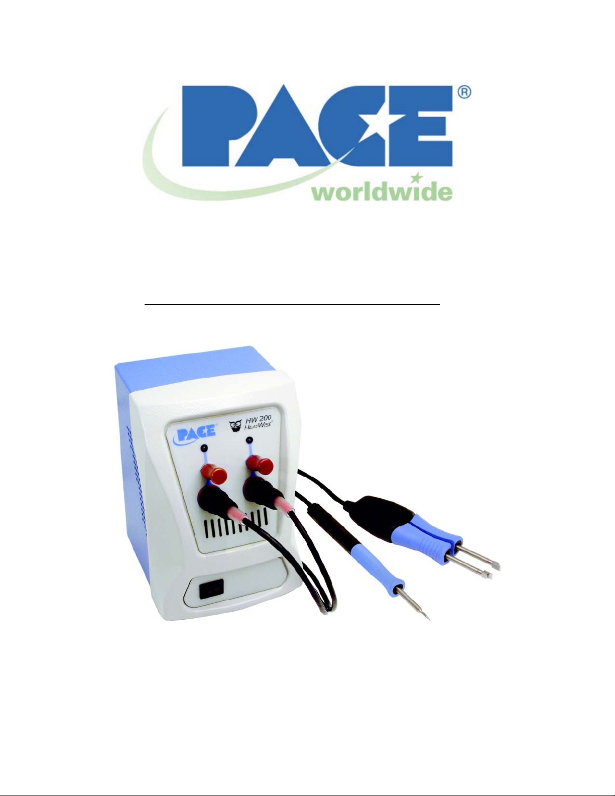
Operation and Maintenance Manual for the
HW 200 Rework System
P/N 5050-0519, Rev B
Voltage Part Number
HW 200 HEATWISE
HW 200 HEATWISE
™
System 115 VAC 8007-0407
™
System 230 VAC 8007-0408
(Shown with optional TD-100 and MT-100 Handpieces)
Page 2

HW 200 System Operation Manual
Table of Contents
Introduction ..............................................................................................................3
Specifications...........................................................................................................3
Environmental Requirements...................................................................................3
Electrical Specifications ...........................................................................................3
Applicable Regulations.............................................................................................3
Parts Identification....................................................................................................4
Safety.......................................................................................................................5
Safety Guidelines........................................................................................5
System Set-Up.........................................................................................................6
Mounting Options........................................................................................6
System Power-Up.......................................................................................6
Handpieces ..............................................................................................................6
Handpiece Tip & Tool Stand.......................................................................6
Adjusting the Angle of the Cubby................................................................6
Handpiece Connection................................................................................6
Operation of the HW 200 HeatWise System............................................................7
Packing Contents.....................................................................................................8
Replacement Power Modules..................................................................................8
Corrective Maintenance...........................................................................................8
Handpiece...................................................................................................8
Power Source..............................................................................................8
PACEWORLDWIDE Limited Warranty Statement...................................................9
Contact Information..................................................................................................10
©2003 PACE Inc., Annapolis Junction, Maryland
All Rights Reserved
Page 2 of 10
Page 3

HW 200 System Operation Manual
Introduction
The HW 200 is a dual channel power supply that is capable of powering any combination of TD-100
Thermo-Drive Soldering Irons and MT-100 MiniTweezers (both sold separately). Each channel can be
controlled separately and are active simultaneously. The system uses Power Modules to control the
performance level of the attached handpieces and a wide range of Power Modules are available. Power
Modules are clearly visible from a distance so you can tell what performance level operators are using for
quick and easy process verification. The system also comes standard with Auto-Setback and Auto-Off
functions to preserve tip life.
Specifications
Specification
Power
Requirements
HW 200
97-127 VAC 50/60 Hz, 150 W Max
or
197-253 VAC 50/60 Hz, 150 W Max
Dimensions 184mm H x 107mm W x 122mm D
(7.25” H x 4.2” W x 4.8” D)
Weight 3.8 Kgs (8.3 lbs)
Tip to Ground
< 2 Ohms
Resistance
Temperature
Within +/- 5 °C (9 °F), idle tip temperature
Stability
Absolute
N/A
Temperature
Accuracy
Performance Level
Range
Available Power Module Performance Levels: 5, 5.5, 6, 6.5, 7, 7.5, 8, & 8.5
260 °C - 454 °C (500 °F – 850 °F)
Environmental Requirements
Ambient Operating Temperature: 0 ºC to 50 ºC (32 ºF to 120 ºF)
Storage Temperature: -20 ºC to 75 ºC (-4 ºF to 170 ºF)
95% Humidity, non-condensing max.
Electrical Specifications
1.3 Amp 115 VAC, 60 Hz Max OR .7 Amp, 230 VAC, 50 Hz Max
Fuse: 2 Amp, SloBlo 115 V System
1 Amp TimeBlo, 230 V System
Applicable Regulations
The HW 200 system is available in either 115 VAC or 230 VAC versions, which incorporate a highly
responsive, closed loop control system providing up to 150 Watts of total output power. The 230 VAC
version system bears the CE Conformity Marking, which assures the user that it conforms to EMC
89/336/EEC.
The 115 VAC version systems conform to FCC Emission Control Standard, Title 47, Subpart B, Class
A. This standard is designed to provide reasonable protection against harmful interference when the
equipment is operated in a commercial environment.
©2003 PACE Inc., Annapolis Junction, Maryland
All Rights Reserved
Page 3 of 10
Page 4
HW 200 System Operation Manual
O
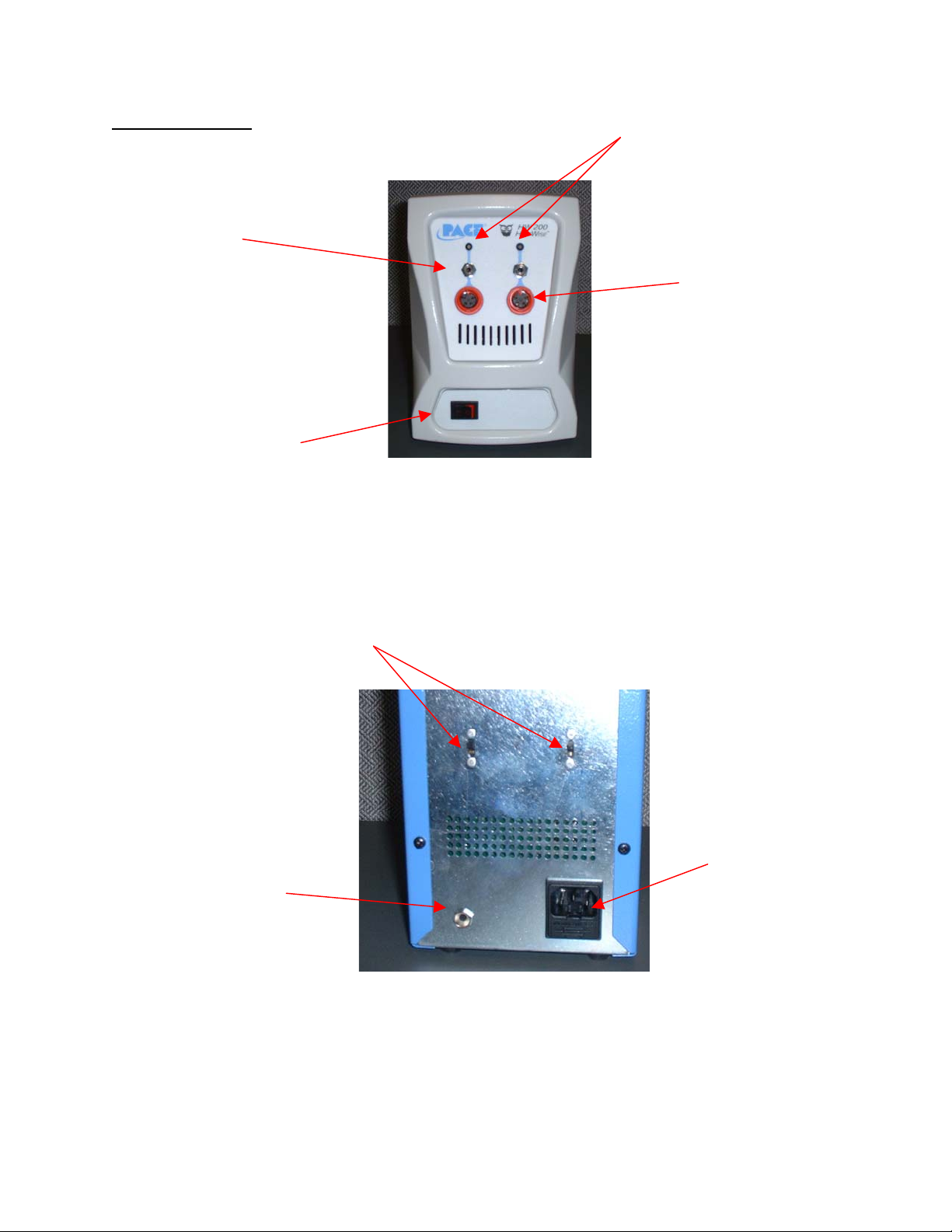
Parts Identification
Power Module Ports
Power Switch
Setback/Auto-
Earth Ground Receptacle
LED Indicators
Power Receptacles
ff Switches
AC Power Receptacle/Fuse
Holder
©2003 PACE Inc., Annapolis Junction, Maryland
All Rights Reserved
Page 4 of 10
Page 5

HW 200 System Operation Manual
Safety
Safety Guidelines
The following are safety precautions that personnel must understand and follow when using or
servicing this product.
1. POTENTIAL SHOCK HAZARD - Repair procedures on PACE products should be performed
by Qualified Service Personnel only. Line voltage parts may be exposed when the
equipment is disassembled. Service personnel must avoid contact with these parts when
troubleshooting the product.
2. To prevent personnel injury, adhere to safety guidelines in accordance with OSHA and other
applicable safety standards.
3. Heater Cartridge Tips are hot when the handpiece is powered on and for a period of time
after power off. DO NOT touch the cartridge. Severe burns may result.
4. PACE Tip & Tool Stands and handpiece cubbies are designed specifically for use with the
associated handpiece and houses it in a manner that protects the user from accidental burns.
Always store the handpiece in its holder. Be sure to place the handpiece in its holder after
use and allow for cooling before storing.
5. Always use PACE systems in a well ventilated area. A fume extraction system such as those
available from PACE are highly recommended to help protect personnel from solder flux
fumes.
6. Exercise proper precautions when using chemicals (e.g., solder paste). Refer to the Material
Safety Data Sheet (MSDS) supplied with each chemical and adhere to all safety precautions
recommended by the manufacturer.
©2003 PACE Inc., Annapolis Junction, Maryland
All Rights Reserved
Page 5 of 10
Page 6
HW 200 System Operation Manual
System Set-Up
Set up the HW 200 system using the following steps and associated images.
1. Store the shipping container in a convenient location. Reuse of the
container will prevent damage if you store or ship your system(s).
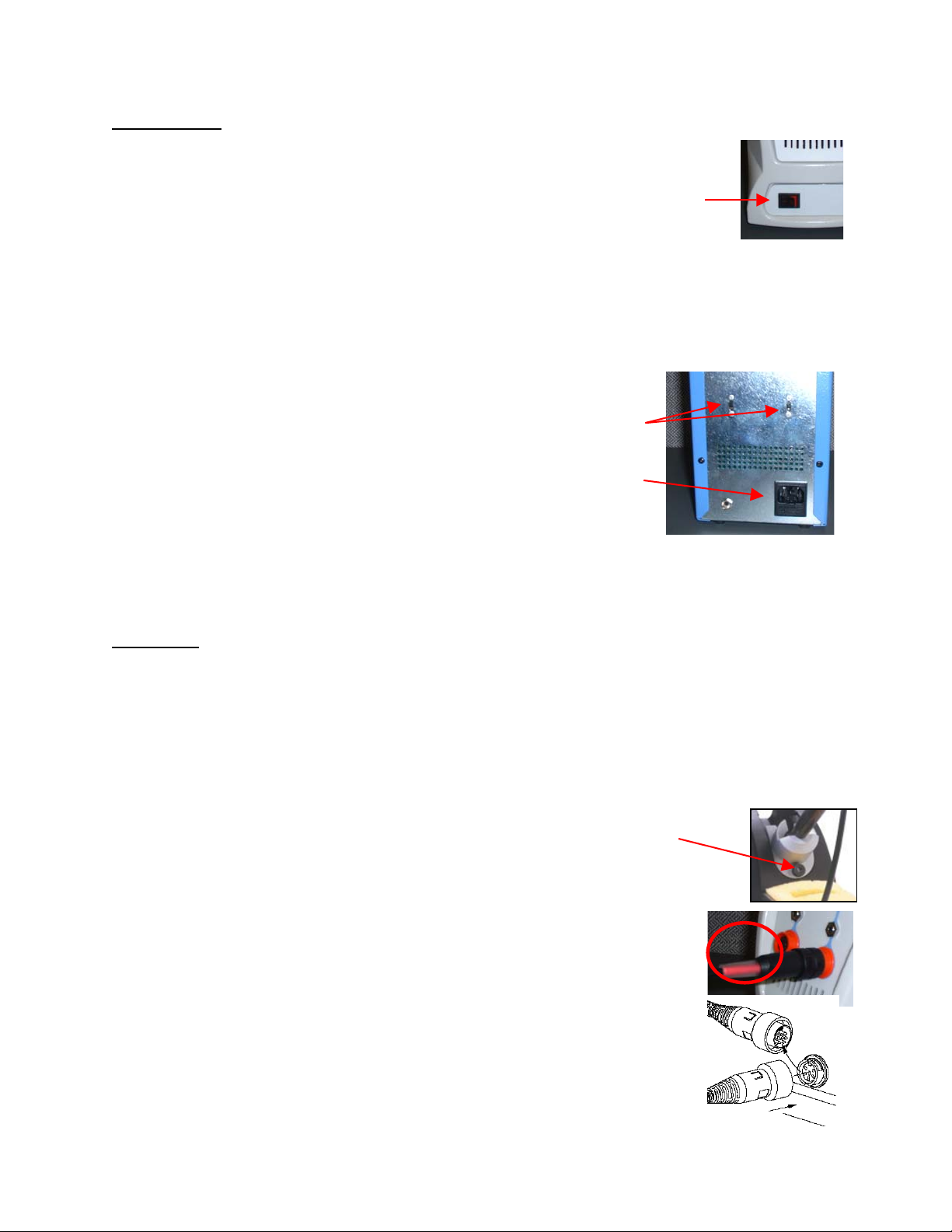
On/Off
Switch
2. Place the Power Switch in the “OFF” or “0” position.
Mounting Options
1. The HW 200 can be placed directly
2. The HW 200 can also be placed inside the optional Tool Chest.
System Power Up
1. Insert the female end of the power cord into the AC Power
Receptacle on the rear panel of the power
source.
2. Plug the prong end (male end) of the power
cord into an appropriate 3 wire grounded AC
supply receptacle.
Setback/AutoOff Switches
AC Power Inlet
CAUTION: To insure operator and ESD/EOS safety, the AC
power supply receptacle must be checked for proper grounding
before initial operation.
NOTE: Ensure that the system is placed in a well-ventilated area. Fume extraction
equipment is recommended when melting solder or heating flux or flux containing solders.
Handpieces
The HW 200 can be used with any combination of TD-100 ThermoDrive Soldering Irons and MT-100
MiniTweezers. These handpieces are purchased separately. The part number for the TD 100 with Tip
& Tool stand is 6993-0242-P1 and the part number for the MT-100 with Tip & Tool stand is 6993-0243P1.
Handpiece Tip & Tool Stands
The Tip & Tool Stand is usually placed on the workbench next to the power source.
Adjusting the Angle of the Cubby
Thumb Screw
The angle of the TD-100 Cubby may be adjusted by loosening the angle thumb screw
slightly, adjusting the cubby to the desired angle, and tightening the thumb screw.
The MT-100 Cubby is not adjustable.
Handpiece Connection
Notice that the handpiece connectors on the HW 200 are red. Only plug in
handpieces that have the red connector.
To connect the handpiece to the power supply, refer to the figure to the right.
Connect the handpiece connector plug into the Power Receptacle in the
following manner.
1. Align guide on the connector with slot on power receptacle.
©2003 PACE Inc., Annapolis Junction, Maryland
All Rights Reserved
Page 6 of 10
Page 7
HW 200 System Operation Manual
2. Insert connector into power receptacle.
3. Turn the connector housing clockwise to lock in place.
Operation of the HW 200 HeatWise System
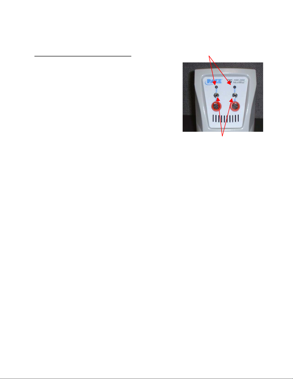
LED Indicators
The HW 200 requires the use of a Power Module. The Power
Module selects the desired heat/performance level for
operation. The HW 200 comes standard with two #7 Power
Modules. Additional Power Modules are available in
performance levels of 5, 5.5, 6, 6.5, 7.5, 8, and 8.5. Please
refer to the Accessory Section for Power Module part numbers.
A heat level of 5 corresponds to a nominal temperature of 500
°F; a heat level of 6.5 corresponds to a nominal temperature of
650 °F, etc. Actual temperatures may vary slightly due to tip
geometry.
Verify the following:
a) Power cord connection between an appropriate AC
supply receptacle and the power source.
b) Handpiece connection to the power source.
Power Module Ports
c) Desired Power Module is installed.
If the power is turned on while a Power Module is not installed, or if the Power Module is removed
during operation, the system will turn itself off and the LED indicator light on the front panel will turn
red.
To operate the unit, please make sure the set-up procedure has been followed. Then follow the
procedure below.
1. If using the TD-100 handpiece, make sure the desired Tip Cartridge is installed. If using the
MT-100, make sure the desired pair of tips are installed.
2. Install the desired Power Module into the Power Port on the front of the unit that corresponds
to the appropriate handpiece channel.
3. The LED indicator will turn amber while the tip(s) is(are) heating to the desired performance
level.
4. Once the tip has reached the desired level, the LED indicator will turn green and the system
is ready to use.
To preserve tip life and save energy, the HW 200 system comes standard with Auto-Setback and
Auto-Off Features. These are pre-programmed for 30 minute Auto-Setback and 30 minute Auto-Off,
which can be turned off by the switch on the back of the unit. If the handpiece has not been used for
30 minutes, the channel will enter setback mode, the performance level will be adjusted to 3.5 and
the LED will blink amber. To exit Setback mode, place the tip in the sponge to load it thermally or
turn the Power Switch OFF (“0”) and then back ON (“l”). After another 30 minute period of inactivity
the channel will turn off and the LED will turn off. To exit Auto-Off mode, cycle the system power.
The Setback/Auto-Off feature can be turned off for each channel individually. Refer to the System
Power Up Section for the location of each switch. As received from the factory, this feature is
enabled.
©2003 PACE Inc., Annapolis Junction, Maryland
All Rights Reserved
Page 7 of 10
Page 8
HW 200 System Operation Manual
Packing Contents
Description
HW 200 Power Supply 7008-0255-01 (120 volt version)
Power Module 7 (2) 1207-0362-05-P1
Power Cord 1332-0094 (120 volt version)
Hot Grip Removal Pad 1100-0307-P1
CD Manual CD5050-0459
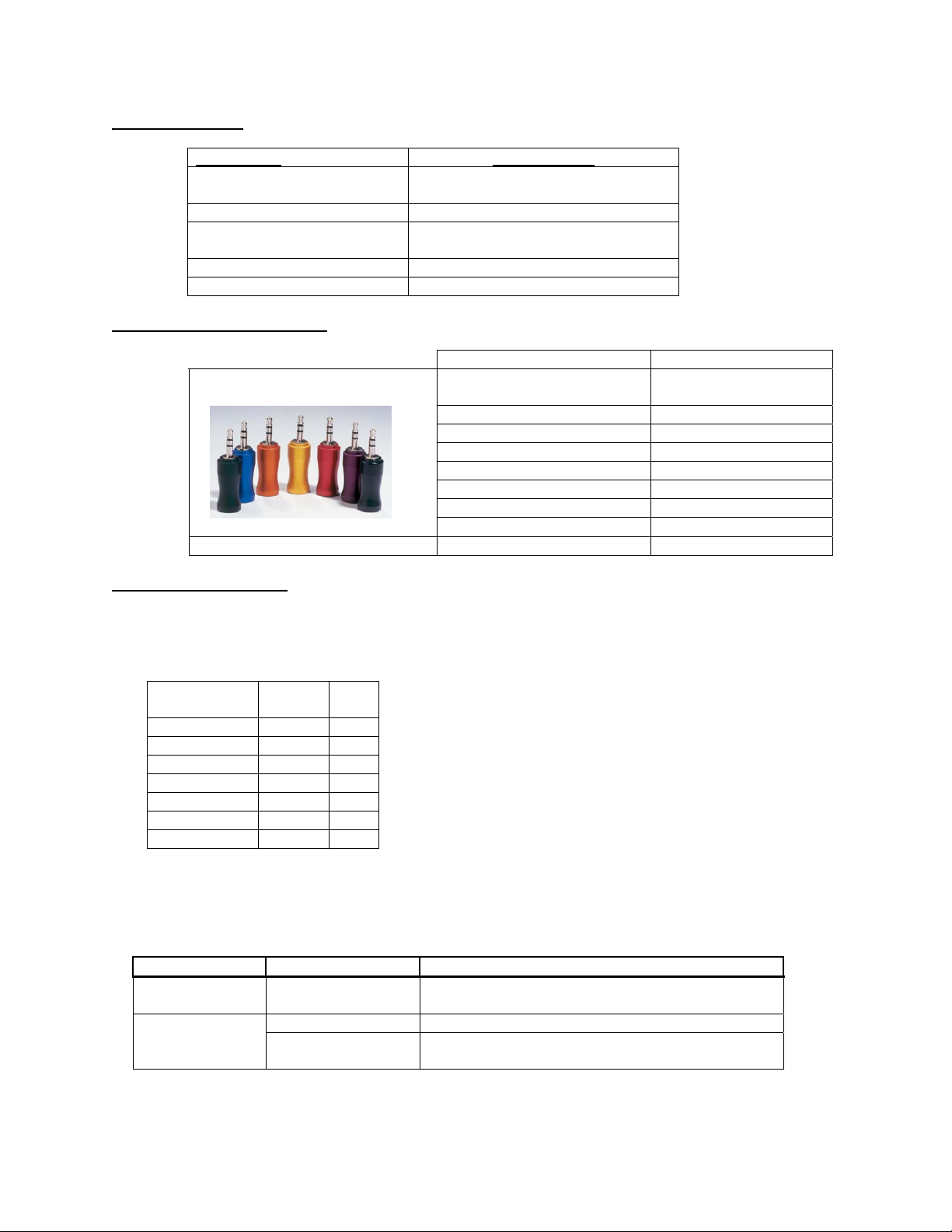
Replacement Power Modules
Corrective Maintenance
Handpieces
Please refer to the respective handpiece manual for the maintenance procedures.
Handpiece/
System
PS 90 x
SX 70/80 x
TT 65 x
TP 65 x
TJ 70/80 x
TD 100 x x
MT 100 x x
Power Source
Refer to the table below. Most malfunctions are simple and easy to correct.
Symptom Probable Cause Solution
No power to
system
not heat
Part Numbers
7008-0255-02 (230 volt version)
1332-0093 (230 volt version)
Description PACE Part Number
TW/HW MTS
Blown Fuse Replace the fuse (located in the AC Receptacle
Defective Heater Change Tip Cartridge Handpiece will
Power Source
Malfunction
Power Source Corrective Maintenance
Power Modules
5/Green 1207-0362-01-P1
5.5/Blue 1207-0362-02-P1
6/Orange 1207-0362-03-P-1
6.5/Gold 1207-0362-04-P1
7/Red 1207-0362-05-P1
7.5/Purple 1207-0362-06-P1
8/Black 1207-0362-07-P1
8.5/Silver 1207-0362-08-P1
Fuse Holder) with one of the same rated value.
Contact PACE
©2003 PACE Inc., Annapolis Junction, Maryland
All Rights Reserved
Page 8 of 10
Page 9

HW 200 System Operation Manual
PACE WORLDWIDE LIMITED WARRANTY STATEMENT
Limited Warranty
Seller warrants to the first user that products manufactured by it and supplied hereunder are free of
defects in materials and workmanship for a period of three (3) years from the date of receipt by such user.
This Warranty as applied to blowers, motor pumps, x-ray tubes, lenses, optical/lighting probes and
cameras is limited to a period of one (1) year. Monitors, computers and other brand equipment supplied
but not manufactured by PACE are covered under their respective manufacturer’s warranty in lieu of this
Warranty.
This warranty does not cover wear and tear under normal use, repair or replacement required as a result
of misuse, improper application, mishandling or improper storage. Consumable items such as tips,
heaters, filters, etc. which wear out under normal use are excluded. Failure to perform recommended
routine maintenance, alterations or repairs made other than in accordance with Seller’s directions, or
removal or alteration of identification markings in any way will void this warranty. This warranty is
available only to the first user, but the exclusions and limitations herein apply to all persons and entities.
SELLER MAKES NO OTHER WARRANTY, EXPRESS OR IMPLIED, AND MAKES NO WARRANTY OF
MERCHANTABILITY OR FITNESS FOR A PARTICULAR PURPOSE.
Seller will, at its option, repair or replace any defective products at its facility or other location approved by
it at no charge to user, or provide parts without charge for installation by the user in the field at user’s
expense and risk. User will be responsible for all costs of shipping equipment to Seller or other location
for warranty service.
EXCEPT FOR THE REMEDY ABOVE DESCRIBED, UNLESS OTHERWISE REQUIRED BY
APPLICABLE LAW, SELLER WILL HAVE NO OTHER OBLIGATION WITH REGARD TO ANY BREACH
OF WARRANTY OR OTHER CLAIM WITH RESPECT TO THE PRODUCTS, OR LIABILITY FOR ANY
DIRECT, INDIRECT, CONSEQUENTIAL, OR INCIDENTAL LOSS OR DAMAGE CAUSED BY OR
OCCURRING IN CONNECTION WITH ANY OF THE PRODUCTS.
Warranty service may be obtained by contacting the appropriate PACE Company or local Authorized
PACE distributor as set forth below to determine if return of any item is required, or if repairs can be made
by the user in the field. Any warranty or other claim with respect to the products must be made with
sufficient evidence of purchase and date of receipt, otherwise user’s rights under this warranty shall be
deemed waived.
For PACE USA Customers:
PACE, INCORPORATED
9030 Junction Drive
Annapolis Junction, Maryland 20701
Tel. 301-317-3588
FAX: 301-498-3252
For PACE EUROPE Customers:
PACE EUROPE LIMITED
Sherbourne House, Sherbourne Drive,
Tilbrook, Milton Keynes
MK7 8HX
United Kingdom
Tel. (44) 1908 277666
WARRANTY SERVICE FAX: (44) 1908 277 777
All other Customers:
Local Authorized PACE Distributor
©2003 PACE Inc., Annapolis Junction, Maryland
All Rights Reserved
Page 9 of 10
Page 10

HW 200 System Operation Manual
Contact Information
PACE Incorporated retains the right to make changes to specifications contained herein at any time,
without notice. Contact your local authorized PACE Distributor or PACE Incorporated to obtain the latest
specifications.
The following are trademarks and/or service marks of PACE, Incorporated, MD, USA:
INSTACAL
POWERPORT
TEKLINK
The following are registered trademarks and/or service marks of PACE Incorporated, Annapolis Junction
Maryland U.S.A.
ARM-EVAC
SODRTEK
VISIFILTER
PACE products meet or exceed all applicable military and civilian EOS/ESD, temperature stability and
other specifications including MIL STD 2000, ANSI/JSTD 001, IPC7711, and IPC A-610.
™
, FUMEFLO™, HEATWISE™, PACEWORLDWIDE™, PERMAGROUND™,
™
, POWERMODULE™, TEMPWISE™, TIP-BRITE™, AUTO-OFF™, and
™
.
®
, FLO-D-SODR®, MINIWAVE®, PACE®, SENSATEMP®, SNAP-VAC®,
®
, SODR-X-TRACTOR®, THERMOFLO®, THERMOJET®, THERMOTWEEZ®,
®
, THERMO-DRIVE®, and TOOLNET®.
www.paceworldwide.com
PACE USA PACE Europe
9893 Brewers Court Sherbourne House
Laurel, MD 20723 Sherbourne Drive
USA Tilbrook, Milton Keynes
MK7 8HX
United Kingdom
Tel: (301) 490-9860 (44) 1908-277666
Fax: (301) 498-3252 (44) 1908-277777
©2003 PACE Inc., Annapolis Junction, Maryland
All Rights Reserved
Page 10 of 10
 Loading...