

Page 1

It is of vital importance, before attempting to operate
your engine, to read the general 'SAFETY
INSTRUCTIONS AND WARNINGS' section on
pages 2-6 of this booklet and to strictly adhere to the
advice contained therein.
Also, please study the entire contents of this
instruction manual, so as to familiarize yourself
with the controls and other features of the engine.
Keep these instructions in a safe place so that you
may readily refer to them whenever necessary.
It is suggested that any instructions supplied with
the aircraft, radio control equipment, etc., are
accessible for checking at the same time.
CONTENTS
SAFETY INSTRUCTIONS AND WARNINGS
ABOUT YOUR O.S. ENGINE
ABOUT THE ENGINE
BASIC ENGINE PARTS
BEFORE STARTING
INSTALLATION OF THE STANDARD ACCESSORIES
MIXTURE CONTROLS
GLOWPLUG
INSTALLATION OF THE ENGINE AND FUEL TANK
2-6
7-9
10
11-14
17
18-20
STARTING THE ENGINE &
RUNNING-IN ('Breaking')
TROUBLE SHOOTING WHEN THE
ENGINE FAILS TO START
CARE AND MAINTENANCE
15
16
ENGINE EXPLODED VIEWS & PARTS LIST
CARBURETOR EXPLODED VIEWS& PARTS LIST
O.S. GENUINE PARTS & ACCESSORIES
THREE VIEW DRAWING
MEMO
21-25
26-27
28-29
30-31
32-33
34
35
36
1
Page 2
SAFETY INSTRUCTIONS AND WARNINGS ABOUT YOUR O.S. ENGINE
Remember that your engine is not a "toy", but a highly efficient internalcombustion machine whose power is capable of harming you, or others, if it is
misused.
As owner, you, alone, are responsible for the safe operation of your engine, so act
with discretion and care at all times.
If at some future date, your O.S. engine is acquired by another person, we would
respectfully request that these instructions are also passed on to its new owner.
The advice which follows is grouped under two headings according to the
degree of damage or danger which might arise through misuse or neglect.
WARNINGS
These cover events which
might involve serious (in
extreme circumstances, even
fatal) injury.
WARNINGS
Never touch, or allow any object to come
into contact with, the rotating
propeller and do not crouch
over the engine when it is
running.
A weakened or loose propeller may
disintegrate or be thrown off and, since
propeller tip speeds with powerful
engines may exceed 600 feet(180 metres)
per second, it will be understood that
such a failure could result in serious
injury, (see 'NOTES' section relating to
propeller safety).
Model engine fuel is poisonous. Do not
allow it to come into contact with the eyes
or mouth. Always store it in a
clearly marked container and
out of the reach of children.
NOTES
These cover the many other
possibilities, generally less obvious
sources of danger, but which, under
certain circumstances, may also
cause damage or injury.
2
Model engine fuel is also highly
flammable. Keep it away fr om open flame,
excessive heat, sources of sparks, or
anything else which might
ignite it. Do not smoke or allow
anyone else to smoke, near to it.
Never operate your engine in an enclosed space. Model engines, like automobile engines, exhaust deadly carbonmonoxide. Run your engine only in an
open area.
Model engines generate considerable
heat. Do not touch any part of your
engine until it has cooled. Contact with
the muffler (silencer),
cylinder head or exhaust
header pipe, in particular,
may result in a serious burn.
3
Page 3
NOTES
This engine was designed for model
aircraft. Do not attempt to use it for any
other purpose.
Mount the engine in your model securely,
following the manufacturers' recommendations, using appropriate screws and locknuts.
Be sure to use the silencer (muffler)
supplied with the engine. Frequent
exposure to an open exhaust may
eventually impair your hearing.
Such noise is also likely to cause
annoyance to others over a wide area.
If you remove the glowplug from the engine
and check its condition by connecting the
battery leads to it, do not hold the plug with
bare fingers.Use an appropriate tool or a
folded piece of cloth.
Install a top-quality propeller of the
diameter and pitch specified for the engine
and aircraft. Locate the propeller on the
shaft so that the curved face of the blades
faces forward-i.e. in the direction of flight.
Firmly tighten the propeller nut, using the
correct size wrench.
4
NOTES
Always check the tightness of the propeller
nut and retighten it, if necessary, before
restarting the engine. Also, check the
tightness of all the screws and nuts before
restarting the engine.
If you install a spinner, make sure that it is
a precision made product and that the
slots for the propeller blades do not cut into
the blade roots and weaken them.
Preferably, use an electric starter. The
wearing of safety glasses is also strongly
recommended.
Discard any propeller which has become
split, cracked, nicked or otherwise rendered
unsafe. Never attempt to repair such a
propeller: destroy it. Do not modify a propeller
in any way, unless you are highly experienced
in tuning propellers for specialized
competition work such as pylon-racing.
Take care that the glow plug clip or battery
leads do not come into contact with the
propeller. Also check the linkage to the
throttle arm. A disconnected linkage could
also foul the propeller.
After starting the engine, carry out any
needle-valve readjustments from a safe
position behind the rotating propeller. Stop
the engine before attempting to make other
adjustments to the carburetor.
5
Page 4

NOTES
Adjust the throttle linkage so that the engine
stops when the throttle stick and trim lever
on the transmitter are fully retarded.
Alternatively, the engine may be stopped by
cutting off the fuel supply. Never try to stop
the engine physically.
Take care that loose clothing (ties, shirt
sleeves, scarves, etc.)do not come into
contact with the propeller.Do not carry loose
objects (such as pencils, screwdrivers, etc.)
in a shirt pocket from where they could fall
through the propeller arc.
Do not start your engine in an area
containing loose gravel or sand.
The propeller may throw such material in
your face and eyes and cause injury.
For their safety, keep all onlookers
(especially small children) well back (at
least 20 feet or 6 meters) when preparing
your model for flight. If you have to carry
the model to the take-off point with the
engine running, be especially cautious.
Keep the propeller pointed away from you
and walk well clear of spectators.
Warning! Immediately after a glowplugignition engine has been run and is still
warm, conditions sometimes exist whereby
it is just possible for the engine to abruptly
restart if the propeller is casually flipped
over compression WITHOUT the glowplug
battery being reconnected. Remember this
if you wish to avoid the risk of a painfully
rapped knuckle!
6
ABOUT THE ENGINE
The O.S. rotary combustion engine, based
on NSU/Wankel System, was the world's
first production model engine of the rotarypiston type as invented by Felix Wankel in
1957 and produced by NSU/Wankel in 1959.
This highly successful application of the
NSU/Wankel System to a power unit of
miniature proportions, has only been made
possible by the expertise of O.S. research
and development engineers and by the
high levels of precision craftsmanship
achieved in its tooling and manufacture.
Operating principle
In place of the piston and cylinder of a
conventional reciprocating engine, the
Wankel motor has a three-lobe rotor which
moves in a circular path, while rotating
about its own axis, within a housing having
an epitrochoidal bore – i.e. a wide-waisted
figure-of eight shape. Planetary rotation is
controlled by an eccentric shaft, an
internally-toothed gear and a fixed pinion
mounted centrally on the rear cover plate.
The tips of the rotor are in continuous
contact with the housing, forming three
chambers, reach of which changes in
volume, with rotation, to effect suction,
compression, expansion and exhaust
phases, as in a four-stroke reciprocating
engine. Spring-loaded tip seals on the rotor
prevent gases from passing from one
chamber to the adjoining one and the rotor
uncovers ports, as in a two-stroke engine,
to control intake and exhaust timing.
7
Page 5

Features
Almost total freedom from vibration
Relatively low noise level Pleasant sound
specific to a rotary engine
Compact shape which enables easier
installation in most models
Commercially available top-quality model
engine fuel containing 15% oil, either
synthetic or castor, can be used.
Note
Do not use commercially available low oil
content fuel.
Since this is a rotary engine designed for
model application, there are some notes to
be followed in order to run it well for a long
time. Also, handling of this engine is somewhat different from that of two-stroke and
four-stroke engines.
1.
Start the engine by an electric starter. Hand
starting is very difficult as the mixture does
not access to the glowplug easily because
the glowplug exists in the housing, not
protruding into the combustion chamber.
2.
Starting is difficult when the atmospheric
temperature is below 10 C.In this case,
warm the engine to approx. 20 C.
8
3.
Prime the engine fairly liberally with fuel and
turn the propeller more than 3 turns so that
all three chambers are primed. Start the
engine in a short time (1~2 seconds).
Prolonged application of an electric starter
(more than 4 seconds) without engine firing
will cause seizing between the side housing
and the rotor due to insufficient lubrication.
(Without firing, the fuel does not have
sufficient lubricating as the oil in the fuel is
diluted with methanol and additives.)
Try to set the needle-valve with one trial.
4.
Setting on the ground lacks sufficient
cooling, and the engine easily overheats.
When the engine is enclosed in a cowl, be
5.
sure to make ventilation holes (outlet hole
Should be lager than inlet hole.), or the
engine will overheat, which results in poor
engine running or seizing in worst case.
Do not remove the carburetor air funnel, or
6.
the engine setting may vary, which results in
poor running.
9
Page 6
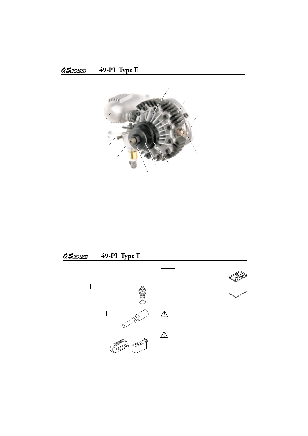
BASIC ENGINE PARTS
RE-2010 Silencer
Air Funnel
Front Housing
Rotor Housing
Engine Mount
Carburetor T ype 21G
BEFORE STARTING
Tools, accessories, etc. The following items
are necessary for operating the engine.
GLOW PLUG
O.S. TypeF glowplug is supplied with
the engine.
GLOWPLUG IGNITER
Commercialy available handy
glowplug heater in which the
glowplug battery and battery leads are integrated.
FUEL PUMP
Alternatively, one of the
purpose-made manual or
electric fuel pumps may be used to transfer fuel
directly from your fuel container to the fuel tank.
Manual
Electric
Glowplug T ypeF
Drive Hub
Propeller washer
Propeller nut
10
FUEL
For this engine, use top quality
methanol-based model engine fuel
containing more than 18% oil either
synthetic or castor and between
5% and 15% nitromethane.
Reminder!
Model engine fuel is poisonous. Do not
allow it to come into contact with the eyes or
mouth. Always store it in a clearly marked
container and out of the reach of children.
Model engine fuel is also highly flammable.
Keep it away from open flame, excessive
heat, sources of sparks, or anything else
which might ignite it. Do not smoke, or allow
anyone else to smoke, near to it.
11
Page 7

Electric Starter and
Starter Battery
Electric
Starter
Required when starting
the engine.
12-Volt lead-acid battery
Fuel Filter
It is recommended to install a good
in-line filter between the fuel tank
and carburetor to prevent entry of
foreign matter into the carburetor.
O.S. Super Filter (Fuel Can Filter)
Install a filter on the outlet tube of your
refueling container to prevent entry of
foreign matter into fuel tank. O.S. ‘Super Filters’
(large and small) are available as optional extras.
O.S. Non-Bubble Weight S
The engine is supplied with a small
sized Non-Bubble Weight. Be sure
to use it in a fuel tank installed in a
model.
Since the distance from the carburetor to the
expansion chamber in the housing is very
short with a rotary engine, even a tiny bubble
from the fuel tank will cause engine breathing.
The Non-Bubble Weight will prevent from
sucking bubbles.
This Non-Bubble Weight can be used for
reciprocating engines. Especially it is suitable
for helicopter engines and big engines which
generate bubbles due to vibration. Also, it is
suitable for sub tank for helicopter as it has
small dia. of 10mm.
12
Fuel Tank
A fuel tank of approximately
320cc capacity is suggested.
This allows around 10-12 minutes flying time,
dependent upon the type of fuel used, the size
of propeller and on the amount of full-throttle to
part-throttle operation throughout the flight.
Spinner
Since the 55AX is intended to be
started with an electric starter, the
addition of a spinner assembly for
centering the starter sleeve is desirable. Use a
heavy-duty, well balanced spinner either of
metal or plastic.
SILICONE FUEL LINE
Heatproof silicone tubing of approx.
5mm o.d. and 2.5mm i.d. is
required for the connection between the fuel tank
and engine.
Propellers
The choice of propeller depends on the design
and weight of the aircraft and the type of flying
in which you will be engaged.
Determine the best size and type after
practical experimentation. As a starting point,
refer to the props listed in the accompanying
table. Slightly larger, or even slightly smaller,
props than those shown in the table may be
used, but remember that speed the propeller
noise will increase if blade tip is raised, due to
higher rpm or if a larger-diameter/lower-pitched
prop is used.
SIZE(DxP)
9x6-7, 10x4-6, 11x4-5
The above propeller sizes are just for a guide.
13
Page 8

Warning:
Make sure that the propeller is well
balanced. An unbalanced propeller and/or
spinner can cause serious vibration which
may weaken parts of the airframe or affect
the safety of the radio-controlled system.
DO NOT forget the WARNINGS and NOTES
on propeller and spinner safety given on
front pages.
Reminder!
Never touch, or allow any object to come into
contact with, the rotating propeller and do not
crouch over the engine when it is running.
Model
Suitable model is the one designed for twostroke 32~40 size engines. (Guide weight
2,000~2,500g)
14
INSTALLATION OF THE
STANDARD ACCESSORIES
STANDARD ACCESSOIES
Glow Plug Type F
(installed on the engine)
RE-2010 Silencer Assembly
Silencer Body
Pressure Nipple (No.7)
Silencer Retaining Screw
Non-Bubble Weight S
INSTALLING THE GLOWPLUG
Install washer on glowplug and insert
carefully into rotor-housing, making sure
that it is not cross-threaded before
tightening firmly.
INSTALLING SILENCER
Be sure to apply silicone sealant at the joint
of silencer and engine and also use spring
washers when fastening retaining screws.
Carburetor is designed to use a muffler
pressurized fuel feed system. Avoid big fuel
level difference, and be sure to use a muffler
pressure.
15
Page 9

MIXTURE CONTROLS
Mixture Control Screw
Throttle Stop Screw
The Mixture Control Screw
This meters fuel flow at part-throttle and idling
speeds to ensure reliable operation as the
throttle is opened and closed. The Mixture
Control Valve is factory set for the approximate
best result. First run the engine as received and
readjust the Mixture Control Screw only if
necessary.
Needle Valve
Two mixture controls are provided on this
Carburetor.
The Needle Valve
When set to produce maximum power at full
throttle, this establishes the basic fuel/air
mixture strength. The correct mixture is then
maintained by the carburetor's built-in automatic
mixture control system to cover the engine's
requirements at reduced throttle settings.
GLOWPLUG
Since the compatibility of the glowplug
and fuel may have a marked effect on
performance and reliability, it is suggested
to use the O.S. Type F plug when it is
necessary to replace. Carefully install
plug finger-tight, before final tightening
with the correct size plug wrench.
The role of the glowplug
With a glowplug engine, ignition is initiated by the
application of a 1.5-volt power source. When the
battery is disconnected, the heat retained within the
combustion chamber remains sufficient to keep the
plug filament glowing, thereby continuing to keep the
engine running. Ignition timing is 'automatic' : under
reduced load, allowing higher rpm, the plug becomes
hotter and, appropriately, fires the fuel/air charge
earlier; conversely, at reduced rpm, the plug become
cooler and ignition is retarded.
Mixture Control Screw of the carburetor is set
at basic position ( a little on the rich side) at the
factory. However, minor readjustment will be
required for a fuel used, atmospheric
conditions and a model. Please note during a
running-in period flights should be made with a
slightly rich needle setting. Therefore, during a
running-in period proper carburetor responses
will not be obtained. Adjust it at optimum
position after the running-in is completed.
16
Glowplug life
Particularly in the case of very high performance
engines,
glowplugs must be regarded as expendable
items. However, plug life can be extended and engine
performance maintained by careful use, i.e.:
Install a plug suitable for the engine.
Use fuel containing a moderate percentage of
nitromethane unless more is essential for racing events.
Do not run the engine too lean and do not leave the
battery connected while adjusting the needle.
When to replace the glowplug
Apart from when actually burned out, a plug may
need to be replaced because it no longer delivers its
best performance, such as when:
Filament surface has roughened and turned white.
Filament coil has become distorted.
Foreign matter has adhered to filament or plug
body has corroded.
Engine tends to cut out when idling.
Starting qualities deteriorate.
17
Page 10

INSTALLATION OF THE ENGINE AND FUEL TANK
Use the engine mount supplied with the
engine to install the engine in the model.
Decide the installing position. Any direction
will do.
Attention to tank height
Set the fuel tank position so that carburetor
center line may locate at 1/3 from the tank
top when the model is placed horizontal.
Locate the fuel tank as close as to the
carburetor, or the fuel level difference will
affect the engine running when the model is
upward or downward.
1/3
2/3
Approx. 15mm
After deciding installing position and
direction, remove the engine mount from the
engine by removing three retaining screws.
Firmly bolt the engine’s radial mounting
flange to the model with 4mm or 3.5mm
screws and self-locking nuts.
For carburetor
Plug
(commercially available)
As short as possible
18
120
120
53
3- 4.2
19
Page 11

THROTTLE LINKAGE
Before connecting the throttle to its servo,
make sure that the throttle arm and linkage
safely clear any adjacent part of the airframe
structure, etc., as the throttle is opened and
closed. Connect the linkage so that the throttle
is fully closed when the transmitter throttle
stick and its trim lever are at their lowest
settings and fully open when the throttle stick
is in its fully-open position. Carefully align the
appropriate holes in the throttle arm and servo
horn so that they move symmetrically and
smoothly through their full travel.
NEEDLE-VALVE EXTENSION
The needle-valve supplied with this engine is
designed to incorporate an extension so that,
when the engine is enclosed within the
fuselage, the needle-valve may be adjusted
from the outside. For this purpose, Needle
Valve Extension Cable Set is supplied with the
engine. If a longer extension is reguired, cut a
commercially available rod to the required
length, bend one end to an L shape, insert it
into needle's center hole and secure it by
tightening the set-screw in the needle-valve
knob with 1.5mm Allen key.
1.5mm Allen key.
Needle Valve Extension Cable Set
20
Set Screw
STARTING THE ENGINE & RUNNING-IN ('Breaking-in')
Be sure to use an electric starter to
start the engine.
Never fail to check the tightness of
screws and nuts, especially engine
!
mounting and moving parts (e.g.
throttle lever).
Starting procedure is as follows:
1.
Fill the fuel tank with fuel. When filled,
prevent fuel flowing into the carburetor with
a commercially available fuel stopper, etc.
Release the stopper before starting the
engine.
2.
Make sure that plug element glows red, and
install the plug in the rotor housing.
Element glows when energized.
Replace the plug when the
element does not glow or is
burnt out.
Glow Plug Igniter
WARNING
When checking the plug element hold the
plug with tools, such as pliers, etc.
Do not hold near your face or the fuel
remaining in the filament may burn you.
21
Pliers
Page 12

Check that the needle-valve is closed. (Do
3.
not overtighten.) Now open the needlevalve counter-clockwise 2 turns to the
starting setting.
Mark
Turn needle-valve clockwise to close
Close
(for leaner mixture)
Turn needle-valve counter-clockwise
to open (for richer mixture)
Open
4.
Open the throttle fully and deliver fuel to the
carburetor by applying an electric starter for
a very short time.
Set the throttle valve at 1/3 open from fully
5.
closed position and connect battery leads to
glowplug.
Connect battery leads to glowplug.
6.
Bring electric starter into contact with
7.
spinner-nut or spinner and depress starter
Switch for one to two seconds. Repeat if
necessary. When the engine starts,
withdraw the starter immediately.
8.
When the engine is started, open the throttle
slowly to full open. Run the engine 5~6
seconds without changing needle-valve
position. If the r.p.m. lower due to rich
mixture, close the needle-valve a little.
Now disconnect battery leads and close the
9.
needle-valve slowly one click at a time.
Abrupt closing may stop the engine specially
when the engine is new and running-in is
incomplete.
22
Attention :
Do not choke the carburetor air intake when
applying the starter. This could cause an
excessive amount of fuel to be drawn into the
cylinder which may initiate an hydraulic lock
and damage the engine.
If the engine does not start within 10 repeat
applications of the starter, remove the glowplug, check that it glows brightly and that the
cylinder is not flooded with fuel. (To eject
excess fuel, close needle-valve and apply
starter with glowplug removed.) Then try again.
VERY IMPORTANT!
Before being operated at full power (i.e. at fullthrottle and with the needle-valve closed to its
optimum setting) the engine must be adequately
run-in, otherwise there is a danger of it becoming
overheated and damaged.
How to stop the engine
Pull down the throttle lever and trim lever on
the transmitter fully.
Note:
Make sure that the throttle linkage is made
so that the throttle is fully closed when the
throttle lever as well as trim lever on the
transmitter are fully pulled down.
23
Page 13

RUNNING-IN ("Breaking-in")
For running-in, fit the engine with a wellbalanced propeller intended for actual flight.
Use a fuel mixture as specified. Running-in
procedure is the same as for a conventional
reciprocating model engine. After starting the
motor, open the throttle fully, but use a rich
needle-valve setting to reduce rpm, increase
lubrication and lower running temperature. This
will produce a smoky exhaust but will ensure
that the engine does not become overheated
and damaged during this critical period.
Install the engine with the propeller intended
1.
for your model. Run the engine for one minute with the throttle fully open, but with the
needle-valve adjusted for rich, slow “fourcycle” operation. Then, adjust the needlevalve so that the engine just breaks into
“two-cycle” from “four-cycle” operation, and
run the engine for 2 tanks. (Even when the
exhaust note is not clear, if the r.p.m. lower,
the needle-valve is closed a little too much.)
2.
Fly the model with rich needle-valve setting.
The needle-valve can be gradually closed
after each flight to give more power. However, if the engine shows sings of running
too lean, the next flight should be set rich.
Avoid successive “nose-up” flights.
After a total of ten flights, the engine should
3.
run continuously, on its optimum needlevalve setting, without loss of power as it
warms up.
24
SUBSEQUENT READJUSTMENT
Once the engine has been run-in and the
controls properly set up, it should be
unnecessary to alter the mixture settings;
except to make minor adjustments to the
Needle-Valve occasionally, to take account of
variations in climatic conditions. The use of a
different fuel, however, particularly one
containing more, or less, nitromethane and/or
a different type or proportion of lubricating oil,
is likely to call for some readjustment of the
Needle-Valve. Remember that, as a safety
measure, it is advisable to increase the
Needle-Valve opening by an extra half-turn
counter-clockwise, prior to establishing a new
setting. The same applies if the silencer type is
changed. A different silencer may alter the
exhaust pressure applied to the fuel feed and
call for a revised Needle-Valve setting. The
use of a different glowplug may also require
compensating carburetor readjustments.
CARBURETOR CLEANLINESS
The correct functioning of the carburetor
depends on its small fuel orifices remaining
clear. The minute particles of foreign matter
that are present in any fuel, can easily partially
obstruct these orifices and upset mixture
strength so that engine performance becomes
erratic and unreliable.
O.S.'Super-Filters'(large and small) are
available, as optional extras, to deal with this
problem. One of these filters, installed on the
outlet tube inside your refueling container, will
prevent the entry of foreign material into the
fuel tank. It is also recommended that a good
in-line filter be installed between the tank and
needle-valve. Do not forget to clean the filters
regularly to remove dirt and lint that
accumulate on the filter screen.
Also, clean the carburetor itself occasionally.
25
Page 14

TROUBLE SHOOTING WHEN THE ENGINE FAILS TO START
Four key points
For quick, reliable starting, the following four conditions are required.
1 Good compression. 2 Adequate "glow" at glowplug. 3 Correct mixture.
4 Sufficient electric starter rotating speed.
If the engine fails to start, or does not keep running after being started, check symptoms against the
following chart and take necessary corrective action.
Note: The most common causes of trouble are marked with three asterisks, the less common problems
with one or two asterisks.
Symptom
Engine fails
to fire.
Factor
1
2
3
Cause
Sluggish rotation
Glowplug battery
discharged.
Glowplug element is
burned out
Something wrong with
battery leads.
Engine "flooded" due to
excessive priming.
Insufficient priming.
......
......
Recharge the electric starter battery.
Recharge lead-acid cell or replace dry battery. (Note: An unused, or almost
unused, dry battery may sometimes be of insufficient capacity if it is "old
stock".)
.....
Replace glowplug. Check that applied voltage is not too high.
....
Check glowplug heating using other leads.
....
Close needle-valve fully and remove glowplug, then flip propeller to pump
out excess fuel. (Invert engine, if possible, while pumping out excess). Restart engine. (Priming is not necessary at this time.)
.....
Repeat priming procedure referring to Priming.
26
Corrective action
Symptom
Engine fires
intermittently but
does not run.
Engine fires once
or twice, then
fails to fire.
Engine starts but
rpm decreases
and engine eventually
stops.
Engine starts,
rpm increases
and engine cuts
out.
Engine stops when
the current to the
glowplug is disconnected after starting.
Factor
2
3
1
2
3
3
3
3
2
Cause
Incorrect heating of
glowplug.
Over priming.
Sluggish rotation.
Glowplug battery
discharged.
Insufficient priming.
Mixture too rich.
Fuel not reaching the
engine.
Mixture too rich.
Mismatch of glow plug and
fuel.
.....
........
......
......
.....
.......
.....
.......
Corrective action
Voltage too high or too low. Re-check and readjust referring to "BEFORE
STARTING" .
Continue applying an electric starter. If the engine dos not start after more
than 4 tries, disconnect the current to the glowplug and leave for a few
minutes., then re-energize plug and apply starter. If the engine still does not
start, remove glowplug and pump out excess fuel by applying the starter.
Then re-start. (Priming is not necessary.)
Recharge the electric starter battery.
Recharge lead-acid cell or replace dry battery.
(Note: An unused, or almost unused, dry battery may sometimes be of
insufficient capacity if it is "old stock".)
Repeat priming procedure referring to Priming.
Close needle-valve half turn (180 ) and wait for several minutes then restart.(Priming is not necessary.)
Make sure that tank is filled with fuel. Check that there is not something
wrong with the fuel line (kinked or split). Check that carburettor is not
clogged with dirt.
Close the needle-valve a little before disconnecting current to the glowplug.
...
Change fuel or glowplug.
27
Page 15

CARE AND MAINTENANCE
Please pay attention to the matters
described below to ensure that your engine
serves you well in regard to performance,
reliability and long life.
As previously mentioned, it is vitally important
to avoid operating the engine in conditions
where dust, disturbed by the propeller, may
be deposited on the engine and enter its
working parts.
Install an in-line fuel filter between the tank
and carburetor to prevent dirt and dust in the
tank from entering the carburetor.
Clean these filters periodically.
If these precautions are neglected, restriction
of fuel flow may cause the engine to cut out,
or the fuel/air mixture to become too lean
causing the engine to overheat.
Remember to keep your fuel container
closed to prevent foreign matter from
contaminating the fuel.
Install a fuel filter to prevent dirt and dust in
the fuel container from entering the fuel tank.
O.S. Super Filters (L) and (S) are available
as optional extras.
Do not close the needlevalve and mixture
control valve too far as this will cause a lean
setting and over heating of the engine. This
can, in turn, create nitromethane oxide
leading to internal rusting of the engine.
Always adjust the needlevalve slightly on the
rich side of peak rpm.
Do not leave unused fuel in the engine at the
conclusion of a day’s flying. Accepted
practice is to cut off the fuel supply while the
engine is still running at full throttle, then
expel as much fuel residue as possible by
turning the engine over 5-10 seconds with
the electric starter. Finally, inject some afterrun oil through the glowplug hole and turn the
engine over several times by hand.
The use of modern high-performance alcohol
based model engine fuels, while promoting
cooler running, improved anti-detonation
combustion and increased power, have the
disadvantage of causing corrosion due to the
acid by-products of combustion. The use of
nitromethane in the fuel can also contribute
to the problem.
28
When the engine is not to be used for some
months (for example, as between flying
seasons), a worthwhile precaution is to
remove it from the airframe and, after
washing off the exterior with alcohol (not
gasoline nor kerosene), remove carefully the
carburetor with intake pipe, glow plug and all
silicone tubing and put them safely aside.
Then, immerse the engine in a container of
alcohol. Rotate the crankshaft while the
engine is immersed. If foreign matter is
visible in the alcohol, rinse the engine again
in clean alcohol. Finally, shake off and dry
the alcohol ,and inject some after-run oil in
the glowplug hole and rotate the crankshaft
several times by hand.
Reinstall the carburetor with intake pipe and
glowplug on the engine and keep it in a dry
place after putting in a vinyl bag.
29
Page 16

ENGINE EXPLODED VIEW
C.M3x25
4
6
2
1
3
7
5
C.M2.6x8.6
8
3-1
14
14-1
N.+M3.5x5
13
12
9
10-1
11
10-2
10
20
C.M2.6x5
17
18
15
C.M2.6x7
22
24
25
25-1
C.M3x8
23
21
19
Type of screw
16
C...Cap Screw M...Oval Fillister-Head Screw
F...Flat Head Screw N...Round Head Screw S...Set Screw
30
Page 17

ENGINEN PARTS LIST
No.
Code No.
23210007
1
23209003
2
41612020
3
41826005
3-1
41625000
4
41622020
5
41601000
6
41614010
7
41614100
8
41604010
9
41602020
10
41820001
10-1
41807004
10-2
31
11
12
13
14
14-1
15
16
17
18
19
20
21
22
23
24
25
25-1
41827002
41815009
41618030
41635020
22681957
71615009
41830000
41603000
22681953
41609000
41621000
41611000
45067319
41616020
41624010
41633000
41634010
71531010
The specifications are subject to alteration for improvement without notice.
Propeller Nut
Propeller Washer
Drive Hub
Woodruff Key
Shaft Spacer
Housing Assembly Screw Set
Front Housing
Crankshaft Ball Bearing (F)
Front Bearing Retainer
Eccentric Shaft
Rotor Housing Assembly
Rotor Gear Retaining Screw
Seal Spring (6pcs.)
Thrust Washer (2pcs.)
Rear Bearing
Carburetor Complete (Type 21G)
RE-2010 Silencer Assembly
Pressure Nipple (No.7)
Glow Plug Type F
Housing Assembly Tubular Dowels (2pcs.)
Rear Housing
Nipple No.1
Fixed Gear
Fixed Gear Retaining Screw (4pcs.)
Rear Counter Weight
Rear Counter Weight Retaining Screw
Rear Cover
Rear Cover Retaining Screw (6pcs.)
Engine Mount
Engine Retaining Screw (3pcs.)
Non-Bubble Weight S
Description
Page 18

CARBURETOR EXPLODED VIEW
4
5
1
2
S.M3x3
3
N.+M3.5x5
6
Type of screw
C...Cap Screw M...Oval Fillister-Head Screw
F...Flat Head Screw N...Round Head Screw S...Set Screw
CARBURETOR PARTS LIST
Code No.
No.
1
41618600
2
41618410
3
41618200
4
41618300
5
22681320
6
41618120
7
41618930
7-1
22681980
7-2
24981837
7-3
26381501
7-4
46181940
7-5
46181941
7-6
26711305
7-7
46181950
8
21015001
9
23081706
Specifications are subject to alteration for improvement without notice.
9
8
7-7
7-5
32
Mixture Control Screw
Throttle Lever Assembly
Carburetor Rotor
Air Funnel
Throttle Stop Screw
Carburetor Body
Needle-valve Assembly
Needle Assembly
"O" Ring (2pcs.)
Set Screw
Needle-valve Holder Assembly
Needle-valve Holder
Ratchet Spring
Fuel Inlet
Carburetor Rubber Gasket
Carburetor Retaining Screw
Description
7-6
7-2
S.M3x3
7-3
7-4
7
7-1
33
Page 19
O.S. GENUINE PARTS & ACCESSORIES
SPINNER NUT
1/4"-28(L)
(23024009)
SUPER FILTER
)
(72403050)
(L
LONG PROPELLER
NUT SETS
(73101000)
CAP SCREW SETS
(10pcs./sets)
M2.6x5
(79871010)
M2.6x7
(79871020)
M3x8
(79871110)
The specifications are subject to alteration for improvement without notice.
SILENCER EXTENSION
ADAPTORS SET
(41651300)
Adaptor L12
SPRING WASHER
(20pcs.)
3.5(Black)
(79872035)
34
Adaptor L20
M3.5x6 (4pcs.)
LONG SOCKET WRENCH
WITH PLUG GRIP
(71521000)
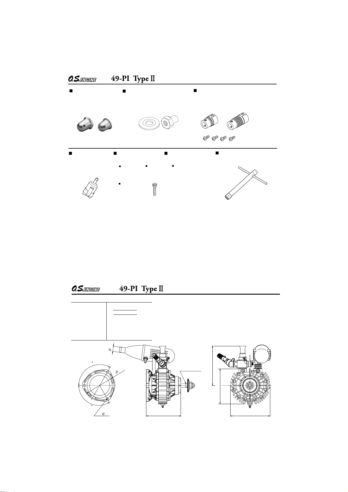
SPECIFICATIONS
Displacement
■
Bore
■
Stroke
■
Practical R.P.M.
■
Power output
■
Weight
■
120
120
4.97 cc (0.303 cu.in.)
2,500-18,000 r.p.m.
1.1 ps / 17,000 r.p.m.
450 g (15.88 oz.)
(Silencer and Engine Mount
are contained.)
9
53
THREE VIEW DRAWING
UNF 1/4-28
603- 4.2 69
35
68.5
61
Dimensions(mm)
Page 20

36
URL : http://www.os-engines.co.jp
C
Copyright 2006 by O.S.Engines Mfg. Co., Ltd. All rights reserved. Printed in Japan.
6-15 3-Chome Imagawa Higashisumiyoshi-ku
Osaka 546-0003, Japan
TEL.(06) 6702-0225
FAX.(06) 6704-2722
60091860 090600
 Loading...