

Page 1
INSTRUCTIONS FOR O.S. TYPE 40C AUTOMATIC CARBURETTOR
This carburettor, as fitted to the O.S. MAX-46FX-H RING helicopter engine, incorporates an automatic
mixture control device which ensures that the engine receives a correctly balanced mixture of fuel and air at
all throttle settings. It ensures steady revolutions and a smooth response for reliable helicopter ascent and
descent.
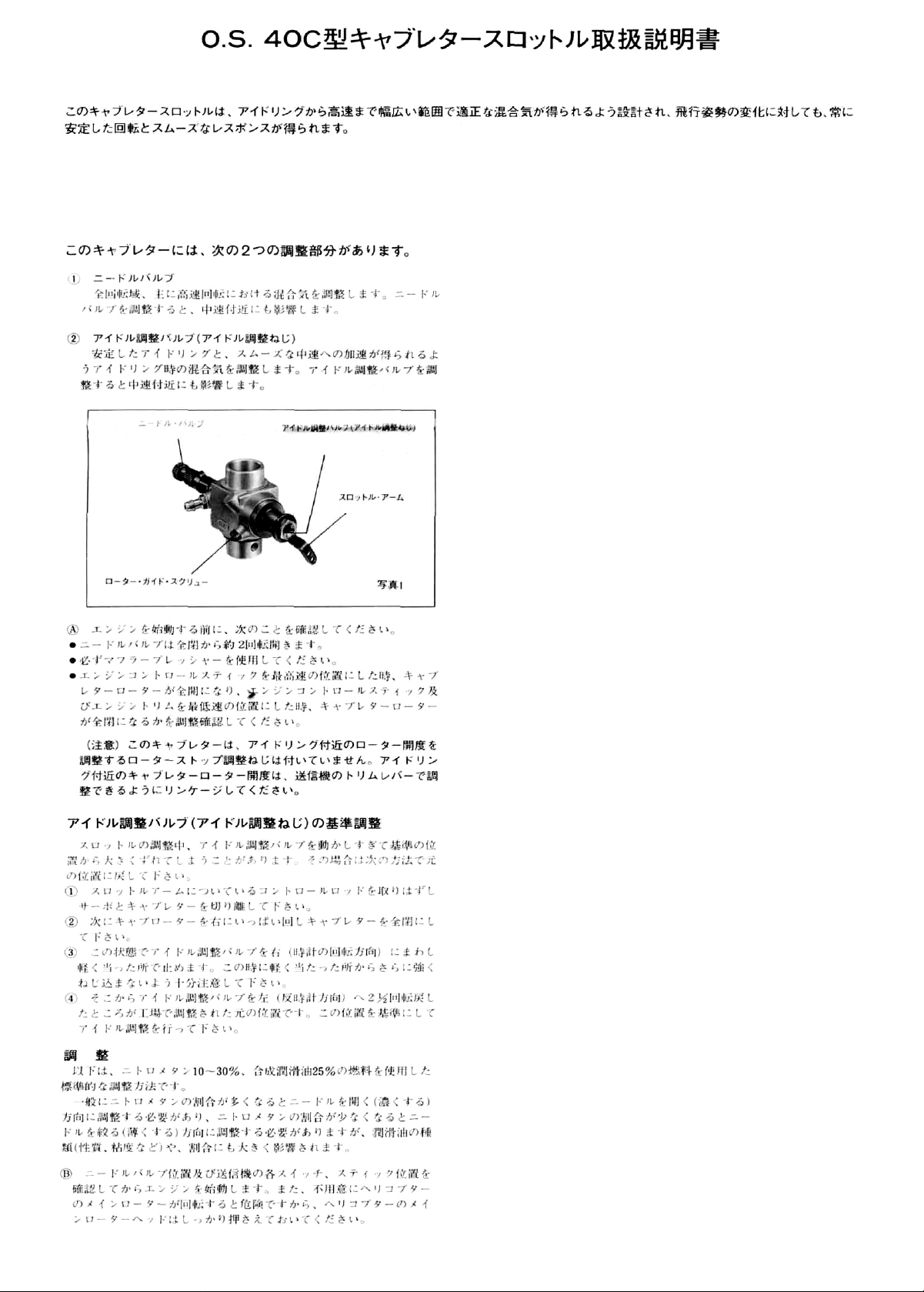
Two adjustable controls are provided on this carburettor.
• The Needle Valve:
When set to produce maximum power at full throttle, the
Needle Valve establishes the basic fuel/air mixture
strength. This is then maintained by the carburettor's
automatic mixture control system to cover the engine's
requirements at reduced throttle settings.
•The
Needle Valve
Rotor Guide Screw
Mixture Control Valve
(Mixture Control Screw)
Throttle Lever
Photo 1
Mixture
For adjusting the mixture strength at part-throttle and
idling speeds, to obtain steady idling and smooth acceleration to medium speeds. The Mixture Control Valve has
been factory set for the approximate best result. First,
run the engine as received, and re-adjust the Mixture
Control Valve only when necessary.
A PROVISIONAL SETTINGS (see ADJUSTMENT CHART)
• Open the Needle Valve 2 turns from the fully closed
position. (Be sure to use a muffler-pressurized fuel feed.)
Note: This carburettor is not fitted with a throttle stop screw.
Instead, idling speed is adjusted by means of the throttle trim
lever on the transmitter. This enables the full r.p.m. range,
from idling to full power, to be controlled by the throttle
stick, and then allows the engine to be stopped, from the
transmitter, by closing the throttle completely with the trim
lever. Set up the throttle linkage as follows:
With the transmitter throttle trim lever fully retarded, adjust
the throttle servo linkage so that the throttle rotor is (a) fully
open when the transmitter throttle stick is fully advanced and
(b) fully closed (i.e. engine stopped) when the stick is fully
retarded.
The idling speed is then set by advancing the throttle trim
lever to the point where the engine runs, steadily and
reliably, at the desired idling speed.
RE-ESTABLISHMENT OF MIXTURE CONTROL VALVESETTING
In the course of making carburettor adjustments, it is just
possible that the Mixture Control Valve may be inadvertently screwed in or out too far and thereby moved beyond its
effective adjustment range.
Its factory setting can be reestablished as follows:
1. Disconnect the throttle linkage by removing the control rod from the throttle lever.
2. Fully close the throttle.
3. Turn the Mixture Control Valve clockwise gently until it
stops, while keeping the throttle fully closed. Do not
over-tighten the valve.
4. Turn the Mixture Control Valve 2-1/2 turns counterclockwise from the above position. This is the basic
(factory) setting.
ADJUSTMENT PROCEDURE
The following adjustments are approximately correct when
using a fuel containing 25% lubricant and 10—30% nitromethane.
Bear in mind that fuels containing relatively large percentages of power-boosting nitromethane operate at richer
mixture settings than are needed for mild fuels and will,
therefore, require the Needle Valve to be readjusted
accordingly. The type and percentage of lubricant used is
also a factor here,as noted later in these instructions.
B As a safety measure, first check the transmitter controls,
including the throttle stick and trim lever positions, and
hold the main rotor securely before starting the engine.
C Warm the engine by allowing it to idle for about 30
seconds. If the engine stops, advance the throttle trim
lever slightly to increase the idling rpm. Then open the
throttle sufficiently to 'float' the model above the ground.
Control Valve
(Mixture
Control
Screw):
Page 2
D If, at this time, the engine is slow to pick up and pro-
duces an excess of exhaust smoke, the mixture is too
rich. Correct this condition by turning the Mixture
Control Screw clockwise. If the mixture is extremely
rich, engine rpm will become unstable: opening the
throttle will produce a great deal of smoke and rpm may
drop suddenly or the engine may stop. This condition
may also be initiated by an excessively prolonged warming-up period.
E If, on the other hand, the mixture is too lean, this will
be indicated by a marked lack of exhaust smoke and a
tendency for the engine to cut out when the throttle is
opened. In this case, turn the Mixture Control Screw
counter-clockwise to enrich the mixture.
F Turn the Mixture Control Screw 30 degrees at a time.
G Having provisionally set the idle mixture,
the next step is
to adjust the mixture for hovering flight.
H Hover the model and actuate the throttle to observe res-
ponse over the medium speed range. If the engine smokes
excessively and throttle response is poor, the mixture is
too rich; in which case, land the model and turn the
Needle Valve clockwise. Do not close the Needle Valve
too much, keeping it a little on the rich side at this stage.
I If, on the other hand, hovering is not stable and response
to the throttle is over-sensitive, or if the engine tends to
overheat,
this
indicates
that
the
mixture
is
too
leanand
should be corrected by turning the Needle Valve counterclockwise.
J When satisfactory hovering flight has been achieved, land
the model again and re-check the engine's idling qualities.
K After about 10 seconds of idling, open the throttle to
'float' the model. If the transition is smooth, the idle
mixture is O.K. If the symptoms of either rich or lean
running are observed, readjust the Mixture Control
Screw accordingly.
L Now adjust the Needle Valve to achieve the best per-
formance when the model is flying at full throttle. If, at
full throttle, acceleration is poor, the exhaust unduly
smoky and the model fails to reach expected straight
line speed, the mixture is too rich and the Needle Valve
setling will need to be reduced.
If, however, after smoothly accelerating to satisfactory
high-speed straight and level flight, power is lost when
the model is pulled up into a climb, the mixture is too
lean. In this case, land the model immediately and readjust the Needle Valve to a richer setting.
M Now re-check hovering performance and, if
necessary,
fine-tune the mixture for hovering flight.
N For helicopters, good throttle response at medium
revolutions (e.g. hovering speeds) is most important,
since this is a power range widely used in helicopter
flight. The optimum fuel/air mixture strength at medium
speeds is dependent on obtaining balanced adjustment of
both the Needle Valve and the Mixture Control Valve.
If both controls are already at their optimum setting,
some modification to these settings may be necessary
to achieve satisfactory mid-range throttle response, but
such readjustments should only be made within the
range where idling reliability and high-speed performance are not unduly compromised.
Readjustments should therefore be carried out as follows:
O If
the mid-range throttle response is not rapid and positive (indicating a rich mid-range mixture), turn the
Needle Valve 2 or 3 clicks clockwise, or turn the Mixture Control Screw 10-20 degrees clockwise.
P If, on the other hand, the response to mid-range throttle
movement is too sensitive (indicating a lean mid-range
mixture), turn the Needle Valve 2 or 3 clicks counterclockwise or turn the Mixture Control Screw 10—20
degrees counter-clockwise.
Q Throttle response at hovering speeds is also affected by
the relationship of the main rotor pitch angle to throttle
opening. If the optimum mid-range throttle response
cannot be obtained by the carburettor adjustments
described above, try adjusting the helicopter's pitch
control characteristics.
Page 3

Remove this with
an 8mm spanner
Photo 2
Dirt and fibrous matter
mostly accumulate here
Photo 3
SUBSEQUENT READJUSTMENTS
Once the engine has been run-in (see engine instructions)
and the carburettor controls properly set up, it should be
unnecessary to alter the mixture settings, except to make
minor adjustments to the Needle Valve occasionally, to
take account of variations in climatic conditions.
The use of a different fuel, however, particularly one containing more, or less, nitromethane and/or a different type
or proportion of lubricating oil, is likely to call for some
readjustment of the Needle-Valve.
Remember that, as a safety measure, it is advisable to
increase the Needle Valve opening by an extra half-turn
counter-clockwise, prior to establishing a new setting. The
same applies if the silencer type is changed. A different
silencer may alter the exhaust pressure applied to the fuel
feed and call for a revised Needle-Valve setting.
The use of a different glowplug, or changes to the main
rotor and its pitch angles may also require compensating
carburettor readjustments.
CARBURETTOR CLEANLINESS
The correct functioning of the carburettor depends on its
small fuel orifices remaining clear. The minute particles of
foreign matter that are present in any fuel can easily partially obstruct these orifices and upset mixture- strength so
that engine performance becomes erratic and unreliable.
It is recommended that fuel is passed through a filter when
the tank is filled and that a good in-line filter is installed
between the fuel tank and carburettor and, furthermore,
that this filter is frequently cleaned to remove dirt and lint
that accumulates on the filter screen. Finally, occasionally
remove the needle-valve holder from the carburettor as
shown in Photo 2 and extract any remaining foreign matter
that may have lodged in the location shown in Photo 3.
ADJUSTMENT CHART
Page 4
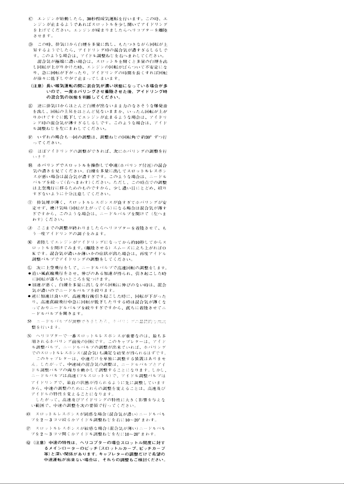
INSTALLATION
After fitting the engine in the helicopter, please observe the following recommendations when linking the throttle servo to the
carburettor.
Locate the servo so that its output arm and the
throttle pushrod are. as closely as possible, directly in line with the carburettor's throttle arm, as
shown.
Note If differential throttle movement is required, make necessary
adjustment at the servo output arm, not at the throttle lever.
When the throttle is fully open or fully closed, the
throttle lever angle should not be more than 45° either
side of the mid-point of its travel (and where it is at a
90' angle to the pushrod), otherwise throttle rotor movement may become inhibited or may even lock up.
Also, some lubricants may affect the throttle rotor
movement.
Please note that the throttle lever angles of the O.S.
Type 40C carburettor are well within these limits
-requiring only 75° from the fully open to fully closed
positions.
CORRECT-
disposed symmetrically, as shown
Use outer hole.
INCORRECT -One-way throttle lever movement should not
be more than 45° \
Throttle
Fully open
position
lever movement should be
Fully closed
position
22781 410
2 2781
420
2 5683 200
25683100
2 4881
824
2 6781 506
4
5581
820
2
2681
953
2 7881 900
2 4981 959
2 4981 837
2 6381 501
2 7381 940
2 6711 305
46215000
2
5081
700
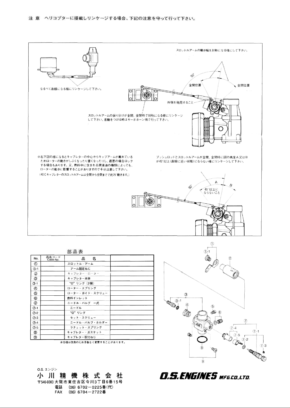
PARTS LIST
Description
Throttle Lever
Throttle Lever Fixing Screw
Carburettor Rotor
Carburettor Body
"0" Ring
Rotor Spring
Rotor Guide Screw
Fuel Inlet
Needle Valve Assembly
Needle
"0" Ring
Set Screw
Needle Valve Holder
Ratchet Spring
Carburettor Gasket
Carburettor Fixing Screw
The specifications are subject to alteration for improvement without notice.
6-15 3-Chome Imagawa Higashisumiyoshi-ku
Osaka 546-0003, Japan TEL. (06) 6702-0225
FAX. (06) 6704-2722
© Copyright 1996 by O.S. Engines Mfg. Co.. Ltd. All rights reserved. Printed in Japan.
60130340-19907
 Loading...