

Page 1

Factory Packaged Controls
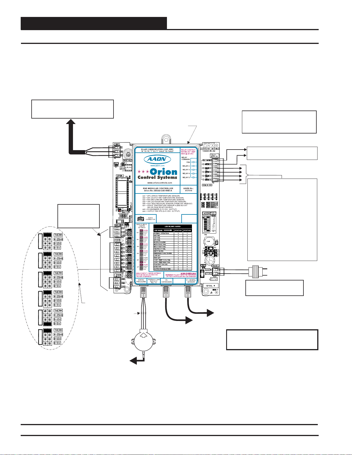
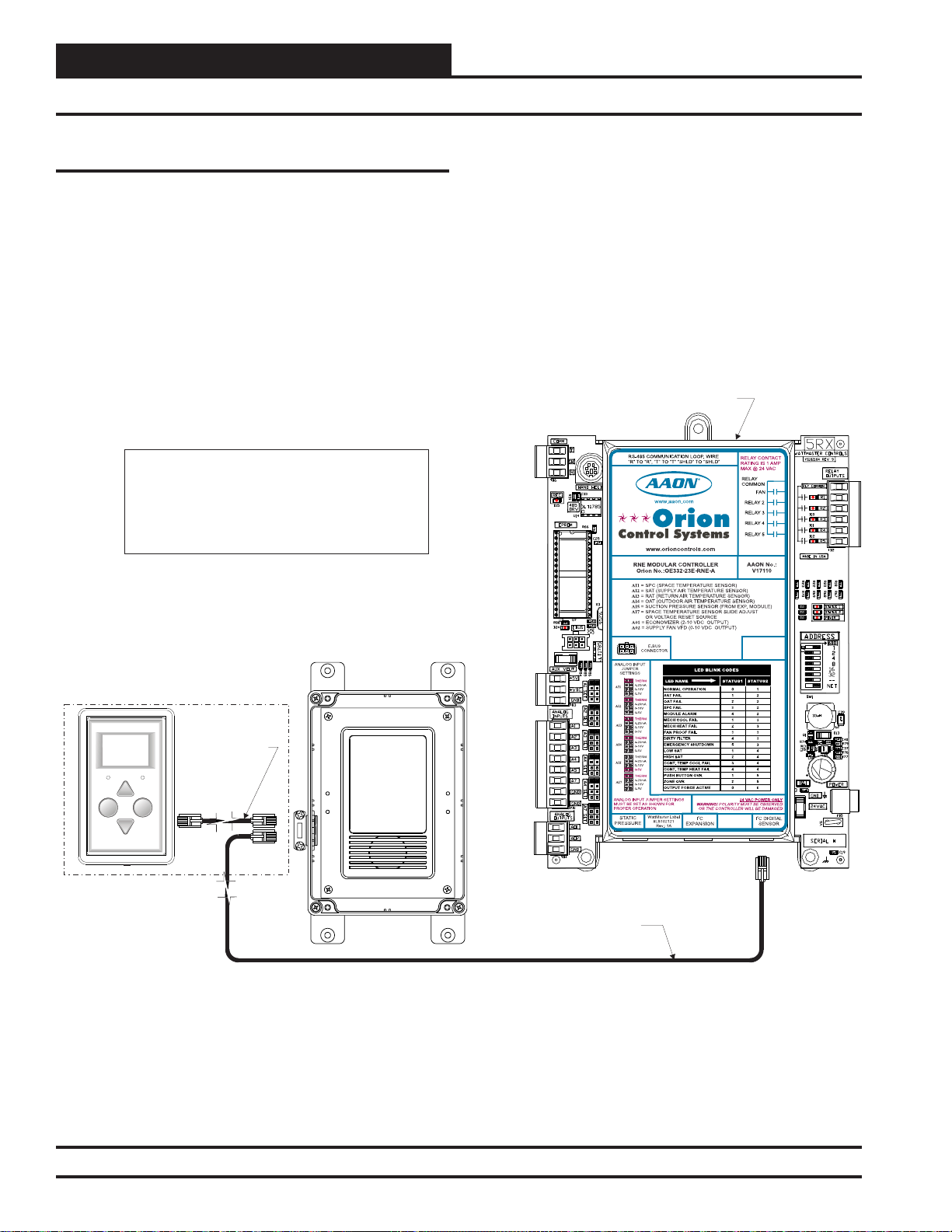
LED BLINK C ODES
LED NAME
STATUS1
STATUS2
NORMAL OPERATION 0 1
OATFAIL 0 2
SATFAIL 1 2
SPC FAIL 3 2
MODULE ALARM 4 2
MECH COOL FAIL 1 3
MECH HEAT FAIL 2 3
FANPROOF FAIL 3 3
DIRTY FILTER 4 3
EMERGENCY SHUTDOWN 5 3
LOW SAT 1 4
HIGH SAT 2 4
CONT. TEMP COOL FAIL 3 4
CONT. TEMP HEAT FAIL 4 4
PUSH BUTTON OVR 1 5
ZONE OVR 2 5
OUTPUT FORCE ACTIVE 0 6
RNE Modular Controller
Technical Guide
RNE Modular Controller: Tulsa - SS1045
Requires Service Tool Code: SS1056 Version 1.0 and up
RS-485 COMMUNICATION LOOP. WIRE
“R” TO “R”, “T” TO “T” “SHLD”TO “SHLD”
www.aaon.com
www.orioncontrols.com
RNE MODULAR CONTROLLER
Orion No.:OE332-23E-RNE-A
AI1 = SPC (SPACE TEMPERATURE SENSOR)
AI2
= SAT(SUPPLY AIR TEMPERATURE SENSOR)
AI3
= RAT(RETURN AIR TEMPERATURE SENSOR)
AI4
= OAT(OUTDOOR AIR TEMPERATURE SENSOR)
AI5
= SUCTION PRESSURE SENSOR (FROM EXP. MODULE)
AI7
= SPACETEMPERATURE SENSOR SLIDE ADJUST
OR VOLTAGE RESETSOURCE
A01
= ECONOMIZER (2-10 VDC OUTPUT)
A02
= SUPPLYFAN VFD (0-10 VDC OUTPUT)
E-BUS
CONNECTOR
ANALOG INPUT
JUMPER
SETTINGS
THERM
4-20mA
AI1
0-10V
0-5V
THERM
4-20mA
AI2
0-10V
0-5V
THERM
4-20mA
AI3
0-10V
0-5V
THERM
4-20mA
AI4
0-10V
0-5V
THERM
4-20mA
AI5
0-10V
0-5V
THERM
4-20mA
AI7
0-10V
0-5V
ANALOG INPUT JUMPER SETTINGS
MUST BE SETAS SHOWN FOR
PROPER OPERATION
WattMaster Label
STATIC
#LB102121
PRESSURE
Rev.: 1A
EXPANSION
WARNING!POLARITY MUST BE OBSERVED
OR THE CONTROLLER WILL BE DAMAGED
2
IC
RELAYCONTACT
RATING IS 1AMP
MAX @ 24 VAC
RELAY
COMMON
FAN
RELAY2
RELAY3
RELAY4
RELAY5
AAON No.:
V17110
24 VAC POWER ONLY
2
I C DIGITAL
SENSOR
Page 2

TABLE OF CONTENTS
OVERVIEW ............................................................................................................................................................4
Features and Applications ..............................................................................................................................4
Part Number Cross Reference ........................................................................................................................6
Parts and Descriptions ....................................................................................................................................7
RNE Controller Dimensions .........................................................................................................................13
VCM-X Expansion Module for RNE Dimensions .........................................................................................14
12-Relay Expansion Module Dimensions ..................................................................................................15
4 Binary Input Expansion Module Dimensions .........................................................................................15
RNE Controller Component Locations ........................................................................................................16
INST ALLATION AND WIRING .............................................................................................................................17
Important Wiring Considerations .................................................................................................................17
RNE Controller Wiring ..................................................................................................................................18
Digital Room Sensor ...................................................................................................................................19
Wall Mounted Space CO
Duct Mounted CO2 Sensor ..........................................................................................................................20
Space Temperature Sensor ........................................................................................................................21
Remote SAT Reset Signal ..........................................................................................................................21
Supply Air & Return Air Temperature Sensor ..............................................................................................22
Outdoor Air Temperature Sensor ................................................................................................................23
Economizer Damper Actuator .....................................................................................................................24
Supply Fan VFD Signal or Zoning Bypass Damper Actuator Signal ...........................................................25
VCM-X Expansion Module Input Wiring for the RNE Controller ................................................................26
VCM-X Expansion Module Output Wiring for the RNE Controller .............................................................27
8 Binary Inputs ............................................................................................................................................28
4 Binary Inputs ............................................................................................................................................29
Outdoor Air Humidity Sensor ......................................................................................................................30
Indoor Wall-Mounted Humidity Sensor .......................................................................................................31
Return Air Mounted Humidity Sensor ..........................................................................................................32
Title 24 Economizer Actuator Feedback .....................................................................................................33
Building Pressure Sensor ...........................................................................................................................33
Building Pressure Control Output ...............................................................................................................34
Modulating Heating Device .........................................................................................................................35
Modulating Chilled Water Valve ..................................................................................................................36
Return Air Bypass .......................................................................................................................................37
12-Relay Expansion Module Wiring and Jumper Settings .........................................................................38
Airfl ow Monitoring Station Installation and Wiring ....................................................................................39
RNE 55 - 105 Ton Unit Two Compressors Wiring ........................................................................................40
Full Digital Module ......................................................................................................................................40
Water Source Heat Pump X-2 Module ........................................................................................................41
Two Condenser Head Pressure Module II ..................................................................................................42
Sensor ...............................................................................................................19
2
WattMaster Controls Inc.
8500 NW River Park Drive · Parkville , MO 64152
Toll Free Phone: 866-918-1100
PH: (816) 505-1100 · FAX: (816) 505-1101
E-mail: mail@wattmaster.com
Visit our web site at www.orioncontrols.com
WattMaster Form: AA-RNE-TGD-01H
Copyright March 2015 WattMaster Controls, Inc.
www.aaon.com
AAON Manual Part Number: V20490
AAON® is a registered trademark of AAON, Inc., Tulsa, OK.
EBTRON® is a registered trademark of Ebtron, Inc., Loris, SC.
Neither WattMaster Controls, Inc. nor AAON®
assumes any responsibility for errors or omissions in this document.
This document is subject to change without notice.
Page 3

TABLE OF CONTENTS
RNE 120 - 140 Ton Unit Four Compressors Wiring .....................................................................................43
Full Digital Module ......................................................................................................................................43
Water Source Heat Pump X-2 Module ........................................................................................................44
Two Condenser Head Pressure Module II ..................................................................................................46
START UP AND COMMISSIONING ....................................................................................................................48
Addressing & Powering Up ...........................................................................................................................48
Programming the Controller .........................................................................................................................49
INPUTS AND OUTPUTS .....................................................................................................................................50
RNE Controller Inputs ....................................................................................................................................50
RNE Controller Outputs .................................................................................................................................50
Expansion Module Inputs & Outputs ...........................................................................................................51
4 Binary Input Expansion Module ................................................................................................................52
12-Relay Expansion Module ..........................................................................................................................52
SEQUENCE OF OPERATION .............................................................................................................................53
Operation Modes ...........................................................................................................................................53
Occupied/Unoccupied Mode of Operation ..................................................................................................53
HVAC Modes of Operation ..........................................................................................................................53
Vent Mode and Cooling Mode .....................................................................................................................53
Economizer Operation ................................................................................................................................55
Supply Air Tempering .................................................................................................................................55
Dehumidifi cation Mode ...............................................................................................................................56
Heating Mode ..............................................................................................................................................58
Morning Warm Up .......................................................................................................................................60
Head Pressure Control ...............................................................................................................................61
Remote Control of HVAC Mode ..................................................................................................................61
Supply Air Temperature Setpoint Reset ......................................................................................................61
Air Flow Monitoring/Control .........................................................................................................................62
Supply Fan Control .....................................................................................................................................62
Duct Static Pressure Control .......................................................................................................................62
Duct Static Pressure Control for Filter Loading ...........................................................................................63
Building Pressure Control ...........................................................................................................................63
CAV/MUA Dual Mode (Hood On/Off Operation) .........................................................................................63
MUA Unoccupied Operation .......................................................................................................................63
IAQ (CO
Pre-Heater Operation ..................................................................................................................................64
Heat Wheel .................................................................................................................................................64
Single Zone VAV Mode ...............................................................................................................................64
Outdoor Air Lockouts ..................................................................................................................................65
Supply Air Cutoffs .......................................................................................................................................65
RNE Controller Alarms ................................................................................................................................66
VAV/Zone Controller Alarms ........................................................................................................................67
Scheduling ..................................................................................................................................................68
Internal Trend Logging ................................................................................................................................68
Force Modes or Overrides ..........................................................................................................................69
VAV Terminal Unit Controller Compatibility .................................................................................................69
VAV/Zone System .......................................................................................................................................69
) Operation ...................................................................................................................................64
2
TROUBLESHOOTING .........................................................................................................................................70
APPENDIX ...........................................................................................................................................................76
System Confi gurations ..................................................................................................................................77
INDEX...................................................................................................................................................................80
RNE Modular Controller Field Technical Guide
3
Page 4

OVERVIEW
Features and Applications
Features
The RNE Modular Controller (OE332-23E-RNE-A) is designed with 7
analog inputs, 2 analog outputs, and 5 relay outputs. Each RNE Controller’s input and output capabilities can be expanded with the VCM-X
Expansion Module (OE333-23-EM), the 12 Relay Expansion Module
(OE358-23-12R), and the 4 Binary Input Expansion Module (OE35601-BI) by means of a modular cable.
The RNE Controller also allows various E-BUS modules to connect
directly to it. These would include the Full Digital Module, the Two
Condenser Head Pressure Module, and the Water Source Heat Pump
Modules.
Each RNE Controller can be confi gured for control of VAV Units (with
or without VAV/Zone Controllers), Constant Volume Units, and MakeUp Air Units. Features include the following:
• Up to a Combined Total of 20 Stages of Heating & Cooling
• Modulating Cooling Outputs (VFD Compressor or Chilled
Water Valve Control)
• Modulating Heating Output ( Hot Water Valve,
Steam Valve, SCR Electric Heat Control)
• Full Integration with the AAON
Natural Gas Controller
• Full Integration with the AAON
Hot Gas Reheat Controller
®
MODGAS-X Modulating
®
MHGRV-X Modulating
• Confi gurable for Heat Pump Applications
• Advanced Dehumidifi cation Capabilities
• Air Flow Monitoring of Outdoor Air, Supply Air,
and Return Air Streams
• Air Flow Control of Outdoor Air Damper
• Single Zone VAV Control
• Primary/Secondary Heating Control
• Adaptive Supply Air Reset
• Selectable Control Sensor
• Fan Proving Interlock
• Dirty Filter Alarm
• Emergency Shutdown Input (Smoke Detector/Firestat or
other Shutdown Conditions)
• Drybulb/Wetbulb Control of Economizer Operation
• Building Pressure Control
• Remote Override Capabilities
• IAQ Economizer Reset
• Title 24 Economizer Certifi ed
• 7-Day, 2-Event-per-Day Scheduling
• 14 Holiday Event Scheduling
• Optimal Start Scheduling
• Trend Logging Capability
• Static Pressure Control for Filter Loading Applications
• Accepts Remote HVAC Mode Selection Via Contact
Closure On VCM-X Expansion Module
• Confi gurable for AAON
®
PAC and DPAC Applications
• Heat Wheel - On/Off Control
• Confi gurable for R22 and R410-A refrigerant
• Head Pressure Control
• Full Digital Control
• Water Source Heat Pump Monitoring
Most common HVAC unit control applications can be confi gured using
only the RNE Controller. If the application requires more inputs and/
or outputs, optional expansion modules are available to provide for additional analog, binary, or digital inputs and outputs as required.
The available expansion module confi gurations allow for 4 or 8 addition-
al binary inputs, 4 additional analog inputs, 5 additional analog outputs,
and up to 16 additional binary (relay) outputs. The various expansion
modules plug into the RNE Controller by means of a modular cable.
4
RNE Modular Controller Field Technical Guide
Page 5

OVERVIEW
Features and Applications
E-BUS Module Applications
The RNE Controller will interface with the Two Condenser Head
Pressure Module (OE370-23-HP2C2-A), the Full Digital Module
(OE370-23-FD-A), and the W ater Source Heat Pump Modules (OE33423-WPM-A, OE334-23-WPM-A20, OE334-23-WPM-A25, OE33423-WPM-A40, and OE334-23-WPM-22-A).
These E-BUS Modules allow independent control of multiple VFD
compressors, control of the condenser fan(s) or valve(s), and monitoring
functions for Water Source Heat Pump Units. See pages 40-47 of this
manual for detailed wiring and application details.
RNE Controller Applications
Variable Air Volume Unit
The RNE Controller can be confi gured to control a VFD Supply Fan
for Duct Static Pressure control. If the unit is not equipped with a VFD,
but Duct Static Pressure control is needed, a modulating Zoning Bypass
Damper can be controlled by the RNE Controller.
VAV units are typically designed for occupied Cooling with Morning
Warm-up Heating. This option is available with the RNE Controller.
The RNE Controller can also be used for a Zoning System that needs
Duct Static Pressure control and Occupied Cooling and Heating. The
RNE Controller also has the ability to be confi gured for Duct Static
Pressure Control by controlling the Supply Fan VFD for the purpose
of maintaining proper Duct Static Pressure in response to varying fi lter
loading conditions.
The RNE Controller allows Dehumidifi cation Priority on a VAV unit.
This could be useful on a building with a very low internal sensible
load, but which has a high internal and/or external latent load. During
VAV Dehumidifi cation, the RNE Controller activates Cooling based on
the Evaporator Coil Temperature and activates AAON® Modulating Hot
Gas Reheat to warm the Supply Air Temperature to the Active Supply
Air Temperature Setpoint.
Constant Air Volume Unit
The RNE Controller can be confi gured to activate a Constant Volume
Supply Fan. In most cases, this is a very basic unit with Space T emperature control. The RNE Controller can be used for kitchen, restaurant, or
lab environments that are 100% Outdoor Air part of the time and Return
Air part of the time. The Hood On input allows the RNE Controller to
know when to switch to 100% Outdoor Air control based on an exhaust
hood activating. The RNE Controller requires Outdoor and Indoor Air
Temperature Sensors to accomplish this application.
Make-Up Air Unit
The RNE Controller can be confi gured for 100% Outdoor Air control
for Make-Up Air. All HVAC Modes are determined from the Outdoor
Air Sensors. The Outdoor Air Volume must always be at least 50% or
higher to be confi gured for Outdoor Air control.
AAON® PAC (Precision Air Control)
This control scheme can only be used on Constant Volume HVAC units
that are equipped with a Return Air Bypass Damper and that use a Space
Temperature Sensor as the Controlling Sensor.
AAON® P AC Control provides improved moisture removal capabilities
while utilizing internal space loads for reheat by redirecting the Return
Air path from the upstream side of the DX Evaporator Coil to the downstream side of the coil.
For AAON® P AC confi gured units, the Return Air Bypass Damper is only
used during the Dehumidifi cation Mode. When the RNE Controller is in
Dehumidifi cation Mode, the Return Air Bypass Damper will modulate
open as the Space T emperature falls below the Cooling Setpoint. Modulation of the Return Air Bypass Damper is controlled using a proportional
range from 0% (when the Space Temperature is equal to the Cooling
Setpoint) up to 100% (when the Space T emperature falls to the halfway
point between the Cooling and Heating Setpoints). A separate Return Air
Damper Actuator will modulate the Return Air Damper slightly further
towards its closed position as the Return Air Bypass Damper opens. This
is to ensure that enough Return Air is bypassed around the Evaporator
Coil through the Return Air Bypass Damper to raise its temperature. The
rate which the Return Air Damper closes while the Return Air Bypass
Damper is open is user-adjustable.
AAON® DPAC (Digital Precision Air Control)
This control scheme can only be used on Constant Volume HVAC
units that are equipped with a Return Air Bypass Damper and VFD
Compressor(s). AAON® DPAC also uses a Space Temperature Sensor
as the Controlling Sensor.
The AAON® DP AC control scheme provides improved moisture removal
capabilities over the AAON® P AC control scheme and provides for tighter
temperature control by combining a VFD Compressor with the Return
Air Bypass Damper. See the Cooling Mode section starting on page 53
for detailed VFD Compressor operation. Refer to AAON® P AC Control
previously described for detailed Return Air Bypass Damper operation.
The VFD Compressor is used during both Cooling and Dehumidifi ca-
tion Modes. The Return Air Bypass Damper is used only during the
Dehumidifi cation Mode.
RNE Modular Controller Field Technical Guide
5
Page 6

OVERVIEW
Part Number Cross Reference
PART DESCRIPTION
RNE Modular Controller OE332-23E-RNE-A V17110
VCM-X Expansion Module OE333-23-EM R69190
VCM-X 12-Relay Expansion Module OE358-23-12R R69180
VCM-X 4 Binary Input Expansion Module OE356-01-BI R82940
Full Digital Module OE370-23-FD-A R74870
Two Condenser Head Pressure Module II OE370-23-HP2C2 V20660
WSHP-X2 Module OE334-23-WSHP-X2 V48820
MHGRV-X Module OE377-00-00042 N/A
MODGAS-X Module OE377-00-00041 N/A
Building Static Pressure Sensor OE258-01 R37030
Bypass Damper Actuator OE281-04 N/A
Cable Coupler for TSDRSC Cables MS000029 N/A
CO
Sensor - Duct Mounted OE256-02 R82970
2
CO
Sensor - Space OE256-01 R82960
2
CommLink 5 Communications Interface OE361-13 V32950
Digital Room Sensor - Temp & Humidity OE217-01 R83870
Digital Room Sensor - Temp. Only OE217-00 R83860
Digital Sensor Cable Assembly TSDRSC-XX N/A
Duct Static Pressure Sensor OE271 P87100
Duct Temperature Sensor - 12" Probe OE231 R44940 / P87140
Duct Temperature Sensor - 6" Probe OE230 R36340
E-BUS Adapter Board OE365-15-EBA V15840
GPC-X Controller OE332-23-GPCX N/A
IP Module Kit OE415-02 R66770
MiniLink Polling Device OE364-22 N/A
Modular Service Tool SD - Operator Interface OE391-12 V28140
Modular System Manager SD - Operator Interface OE392-12 V36570
Outdoor Air RH Sensor - 3% - 0-5 VDC Output OE265-13 R34700
Outdoor Air Temperature Sensor OE250 P87150
Return Air RH Sensor - 3% - 0-5 VDC Output OE265-14 R34650
Room Mounted RH Sensor - 3% - 0-5 VDC Output OE265-11 R34690
Standard Room Sensor - Plain OE210 R31480
Standard Room Sensor - W/ Override OE211 P87040
Standard Room Sensor - W/ Override & Slide Adjust OE213 P94320
Standard Room Sensor - W/ Slide Adjust OE212 P94100
Static Pressure Pickup Tube OE290 S18780
Suction Pressure Transducer OE275-01 N/A
System Manager TS II - Operator Interface OE392-10 N/A
USB-Link 2 Kit OE366 R71870
ORION
PART NUMBER
AAON TULSA
PART NUMBER
6
RNE Modular Controller Field Technical Guide
Page 7
OVERVIEW
Parts and Descriptions
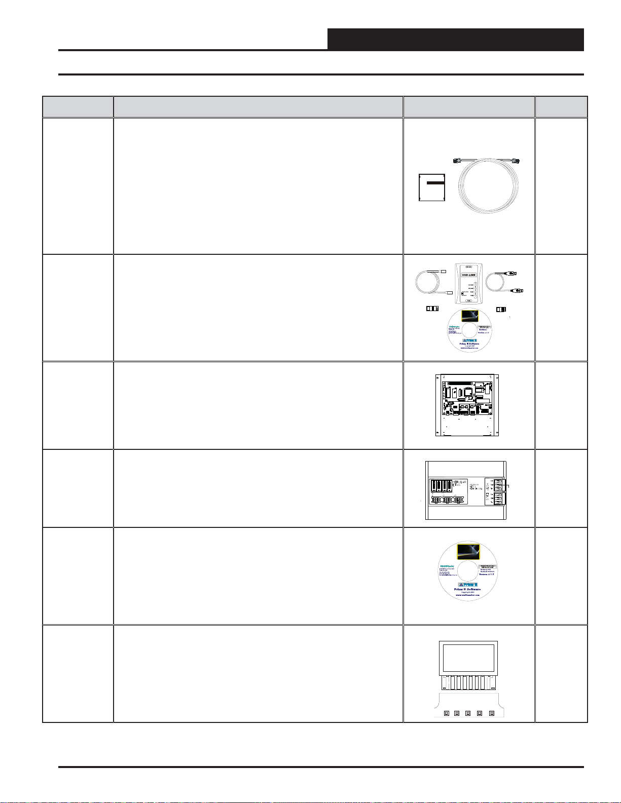
PART NO. PART DESCRIPTION ILLUSTRATION
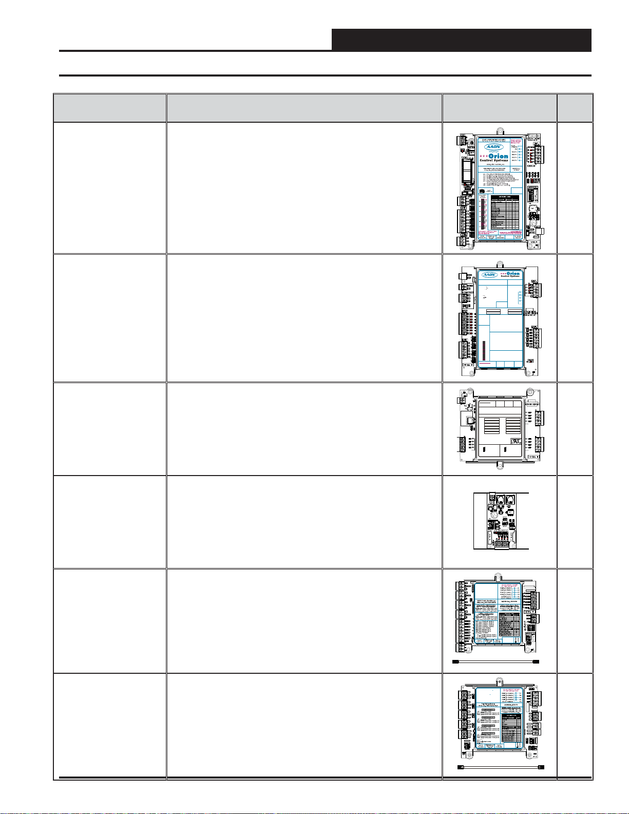
OE332-23E-RNE-A RNE Controller
The RNE Controller provides 7 analog inputs, 2 analog outputs, and 5
relays. It presently allows for the addition of the VCM-X Expansion Module, the 12 Relay Expansion Module, and hte 4 Binary Input Expansion
Module described below.
NOTE: Set-up, programming, and monitoring of the RNE Controller
requires one of the following communication interfaces—Prism 2 FrontEnd Software used with a personal computer, System Manager Touch
Screen II, or Modular Service Tool.
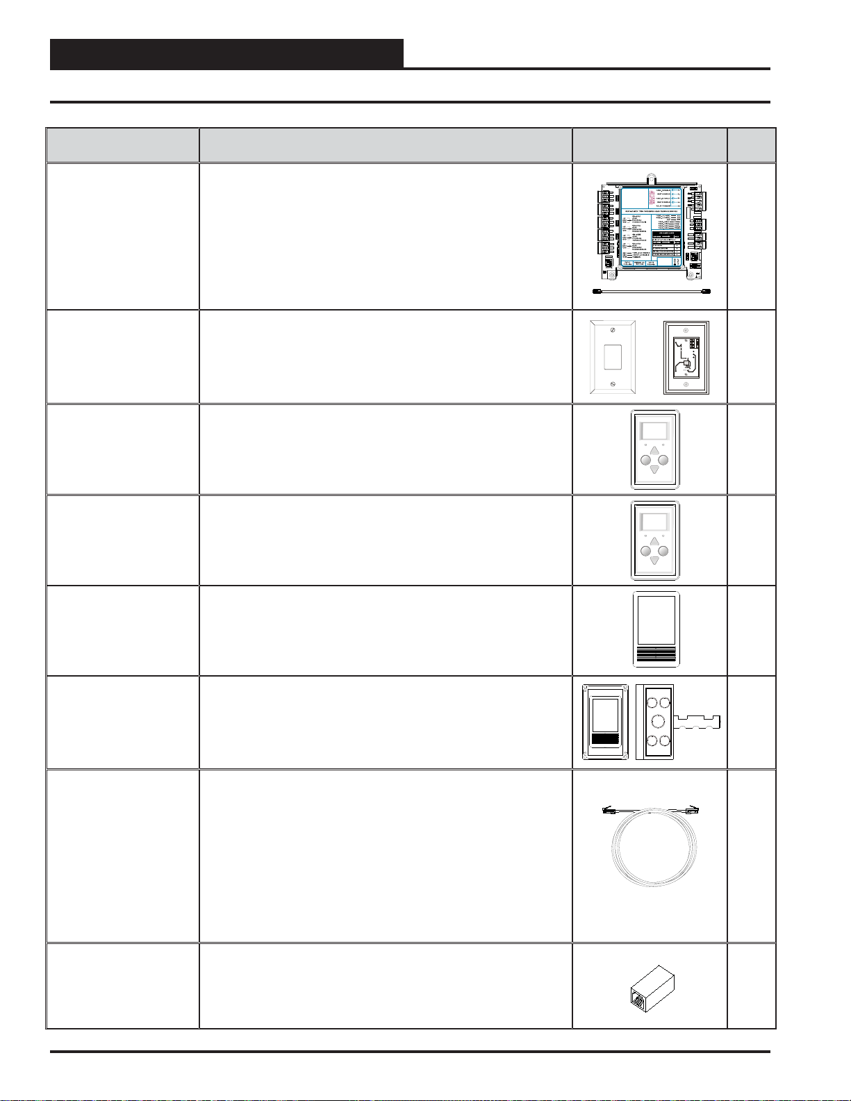
OE333-23-EM VCM-X Expansion Module
Includes: VCM-X Expansion Module mounted in plastic enclosure and
10 ft. I2C cable. The VCM-X Expansion Module adds VAV applications,
building pressure control, head pressure control, water source heat
pump monitoring, and other functions. It provides 4 additional analog
inputs, 2 binary inputs, 5 additional relays, and 3 analog outputs. It
connects with a modular cable to the RNE Controller.
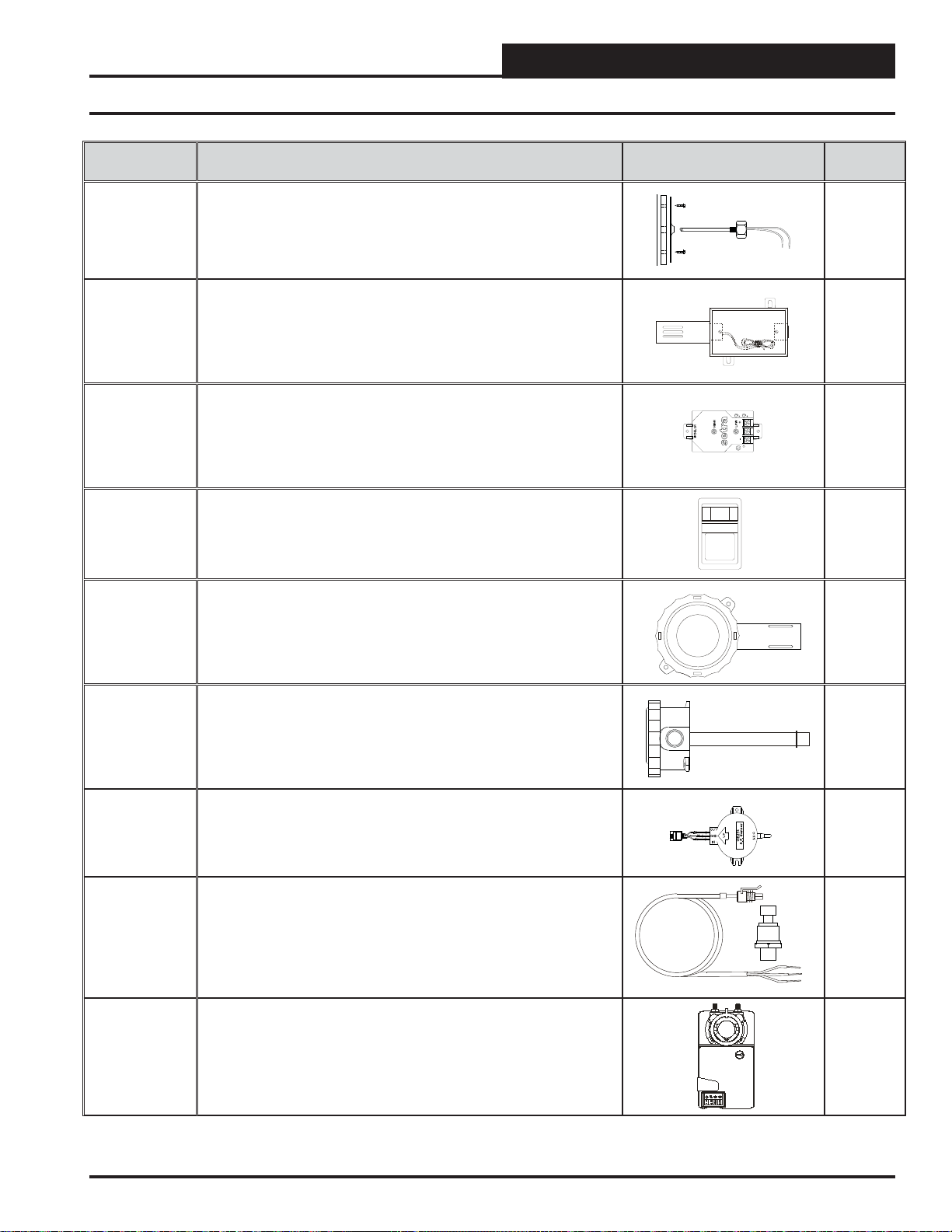
OE358-23-12R VCM-X 12 Relay Expansion Module
Includes: 12 Relay Expansion Module mounted in plastic enclosure
and 10 ft. I2C cable. The VCM-X 12 Relay Expansion Module adds 12
confi gurable relays to the RNE Control System. It connects to the RNE
Controller using the included I2C cable.
POLARITY
WARNING
OBSERVE
POWER
24VAC
GND
EXP1
EXP2
RLY1
RLY2
RLY3
RLY4
RLYCOM
MADE IN USA
24 VAC POWER ONLY
WARNING!POLARITYMUST BE
OBSERVED OR THE BOARD
WILLBE DAMAGED
VCM-X Expansion Module
Orion No.:OE333-23-EM
PR OUT
GND
OE333-23-EM-AVCM-X EXPANSION MODULE
PR OUT
GND
+V
SIG
GND
+V
SIG
GND
RELAY1 = RELAY3 =
RELAY2 = RELAY4 =
RELAY1 = RELAY3 =
ITIS SUGGESTED
THATYOU WRITETHE
DESCRIPTION OF
RELAY2 = RELAY4 =
THE RELAYOUTPUTS
YOUARE USING IN
THE BOXES
ITIS SUGGESTED
PROVIDEDABOVE
THATYOU WRITETHE
WITHAPERMANENT
DESCRIPTION OF
MARKER (SHARPIE®)
THE RELAYOUTPUTS
YOUARE USING IN
THE BOXES
PROVIDEDABOVE
WITHAPERMANENT
ANALOG INPUT
MARKER (SHARPIE®)
JUMPER SETTINGS
MUSTBE SETAS
SHOWN FOR
PROPER
ANALOG INPUT
OPERATION
JUMPER SETTINGS
MUSTBE SETAS
SHOWN FOR
ANALOG INPUT
PROPER
JUMPER
OPERATION
SETTINGS
ANALOG INPUT
AI1
JUMPER
SETTINGS
AI1
AI2
AI2
AI3
AI3
AI4
AI4
24 VAC POWER ONLY
WARNING!POLARITYMUST BE
OBSERVED OR THE BOARD
WILLBE DAMAGED
24 VAC POWER ONLY
WARNING!POLARITYMUST BE
OBSERVED OR THE BOARD
WILLBE DAMAGED
OE358-23-12R 12 RELAYEXPANSION MODULE
RLY1 = RLY7 =
RLY2 = RLY8 =
RLY3 = RLY9 =
RLY4 = RLY10 =
RLY5 = RLY11 =
RLY6 = RLY12 =
NOTE:
ITIS RECOMMENDEDTHAT YOU WRITE THE
DESCRIPTION OFTHE RELAYOUTPUTS YOU
ARE CONNECTINGTOTHE RELAY EXPANSION
MODULE INTHE BOXES PROVIDEDABOVE
USINGAPERMANENT MARKER (SHARPIE)
FOR FUTURE REFERENCE.
J1
EXP1
EXP2
I2C
EXPANSION
www.aaon.com
TO VCM-X INPUT
TERMINALSAI5 & GND
TO VCM-X INPUT
TERMINALSAI5 & GND
SUCTION PRESSURE
TRANSDUCER CONNECTION
FOR HVAC UNITS WITHOUT
DIGITALCOMPRESSOR
SUCTION PRESSURE
TRANSDUCER CONNECTION
FOR HVAC UNITS WITHOUT
DIGITALCOMPRESSOR
BI1= EMERGENCYSHUTDOWN - N.C. INPUT
= DIRTYFILTER - N.O. INPUT
BI2
= PROOF OF FLOW - N.O. INPUT
BI3
= REMOTE FORCED OCCUPIED - N.O. INPUT
BI4
BI1= HOOD ON - N.O. INPUT
= REMOTE FORCED HEATING - N.O. INPUT
BI5
BI2
= DIRTYFILTER - N.O. INPUT
= REMOTE FORCED COOLING - N.O. INPUT
BI6
BI3
= PROOF OF FLOW - N.O. INPUT
= HOOD ON - N.O. INPUT
BI7
BI4
= REMOTE FORCED OCCUPIED - N.O. INPUT
= REMOTE DEHUMIDIFICATION - N.O. INPUT
BI8
= REMOTE FORCED HEATING - N.O. INPUT
BI5
= REMOTE FORCED COOLING - N.O. INPUT
BI6
NOTE:
= SMOKE DETECTOR - N.C. INPUT
BI7
ALLBINARYINPUTS MUST BE 24 VAC ONLY.
= REMOTE DEHUMIDIFICATION - N.O. INPUT
BI8
NOTE:
AO1=BUILDING PRESSURE CONTROL VFD OR
ALLBINARYINPUTS MUST BE 24 VAC ONLY.
DAMPERACTUATOR (0-10 OR 2-10 VDC)
AO2
= MODULATING HEATING SIGNAL
(0-10 VDC OR 2-10 VDC)
AO1=BUILDING PRESSURE CONTROL VFD OR
AO3
= MODULATING COOLING/DIGITALSCROLL
DAMPERACTUATOR (0-10 OR 2-10 VDC)
SIGNAL(0-10 VDC, 2-10 VDC OR 1.5-5 VDC)
= MODULATING HEATING SIGNAL
AO2
THERM
AO4
= RETURNAIR DAMPERACTUATOR
(0-10 VDC OR 2-10 VDC)
4-20mA
(0-10 VDC)
0-10V
= MODULATING COOLING/DIGITALSCROLL
AO3
AO5
= RETURNAIR BYPASS DAMPERACTUATOR
0-5V
SIGNAL(0-10 VDC, 2-10 VDC OR 1.5-5 VDC)
(0-10 VDC)
THERM
= RETURNAIR DAMPERACTUATOR
AO4
THERM
GND
= GROUND FORANALOG OUTPUTS
4-20mA
4-20mA
(0-10 VDC)
0-10V
GND
= GROUND FORANALOG OUTPUTS
0-10V
= RETURNAIR BYPASS DAMPERACTUATOR
AO5
0-5V
0-5V
(0-10 VDC)
THERM
THERM
= GROUND FORANALOG OUTPUTS
GND
AI1= OUTDOORAIR RH SENSOR (0-5 VDC)
4-20mA
4-20mA
= GROUND FORANALOG OUTPUTS
GND
0-10V
AI2
= INDOORAIR RH SENSOR (0-5 VDC)
0-10V
0-5V
0-5V
A3
= ECONOMIZER FEEDBACK
I
THERM
AI4
= BUILDING STATIC PRESSURE (0-5 VDC)
THERM
AI1= OUTDOORAIR RH SENSOR (0-5 VDC)
4-20mA
4-20mA
GND
= GROUND FORANALOG INPUTS
AI2
= INDOORAIR RH SENSOR (0-5 VDC)
0-10V
0-10V
GND
= GROUND FORANALOG INPUTS
0-5V
AI3
= CO2 (0-10 VDC)
0-5V
AI4
= BUILDING STATIC PRESSURE (0-5 VDC)
THERM
4-20mA
GND
= GROUND FORANALOG INPUTS
0-10V
= GROUND FORANALOG INPUTS
GND
I2C
0-5V
EXPANSION
I2C
EXPANSION
SETJUMPERAS
SHOWN WHEN
ONLY
THE 12 RELAY
EXPANSION MODULE
IS USED
EXP1
EXP2
WattMaster Label
#LB102034-01
www.orioncontrols.com
www.orioncontrols.com
WattMaster Label
#LB102034-01-A
Rev.: 1K
WattMaster Label
#LB102043
www.orioncontrols.com
®
J1
SETJUMPERAS
SHOWN WHEN BOTH
THE VCM EXPANSION
MODULEANDTHE
RELAYEXPANSION
MODULEARE USED
AAON No.:
R69190
RELAYCONTACT
RATING IS 1AMP
MAX @ 24 VAC
RELAYCONTACT
RATING IS 1AMP
MAX @ 24 VAC
RELAY1
RELAY2
RELAY
RELAY3
COMMON
RELAY4
RELAY
COMMON
PAGE
NO.
Page
18
OBSERVE
WARNING
POLARITY
I2C
EXPANSION
RELAY1
RELAY2
RELAY3
RELAY4
VCM
I2C
EXPANSION
RELAY
I2C
EXPANSION BOARD
EXPANSION
YS102228 REV 1
RLY5
RLY6
RLY7
RLY8
RLYCOM
RLY9
RLY10
RLY11
RLY12
RLYCOM
Pages
26-28
Page
38
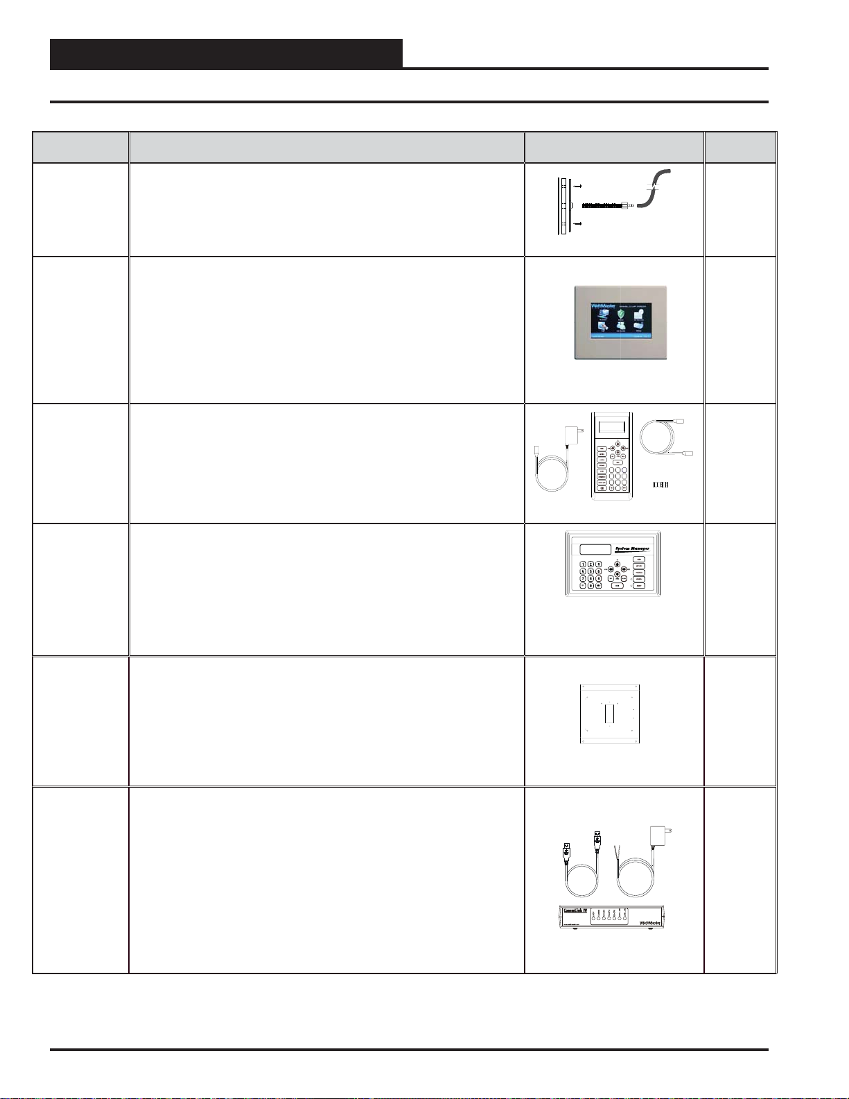
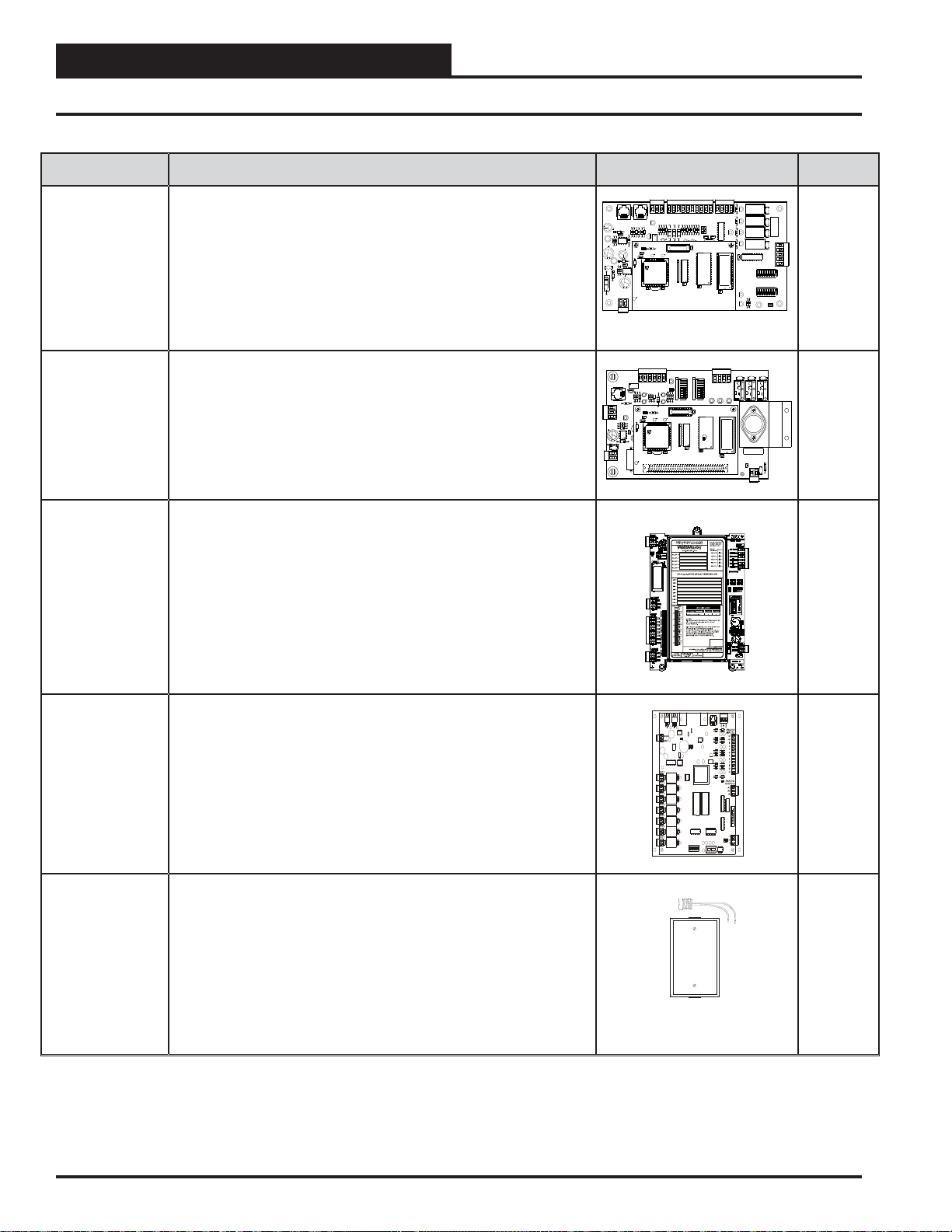
OE356-01-BI VCM-X 4 Binary Input Expansion Module
Includes: 4 Binary Input Expansion Module mounted in Snap Track and
10 ft. I2C cable. Use the 4 Binary Input Expansion Module if your HVAC
unit only requires a Smoke Detector/Firestat, Dirty Filter, Proof of Flow,
or Remote Forced Occupied Inputs or all of these 4 inputs and you don’t
need any of the other inputs or outputs provided by the OE333-23-EM
VCM-X Expansion Module. The module connects to the RNE Controller
using the included I2C cable.
OE334-23-WSHP-X2 Water Source Heat Pump X2 Module
Includes: Water Source Heat Pump X2 Module in a plastic enclosure
with LCD display and E-BUS Modular cable. Provides monitoring and
compressor control for AAON Tulsa Water Source Heat Pump Units.
Used with the RNE Controller.
OE370-23-FD-A Full Digital Module
Includes: Full Digital Module in a plastic enclosure and E-BUS Modular
cable.Used with the RNE Controller. For AAON Tulsa units with multiple
Digital Scroll Compressors and that are not Water Source Heat Pump
Units.
RNE Modular Controller Field Technical Guide
GND
24VAC
Page
VCM BIN EXPBOARD
PWR
YS102364 REV1
COM
BI3
BI4
BI1
BI2
Y102374 REV 0S
WATTMASTER CONTROLS
MADE IN USA
29
Pages
41,44
R12
R53
R54
R11
4751
4751
4751
4751
TB3
+5V
1003
SIG 1
1002
10uF
GND
+5V
1003
www.orioncontrols.com
SIG 2
1002
10uF
GND
C2
+5V
1003
SIG 3
1002
10uF
GND
+5V
1003
SIG 4
1002
10uF
GND
4
R7
R9
300
BIN 1
4
R13
R14
BIN 2
300
1002
R23
COM
1002
R24
1002
R25
1002
R26
ADDRESS
1
OFF
2
4
8
SW1
PWR
D3
R1
D4
R2
D12
R3
D13
R4
Rc
RELAYS
SERIAL#
ANALOG
AO1
AO2
GND
PWM1-
PWM1+
R34 R50
PWM2-
PWM2+
SW2
1002
OFF
1002
1002
1002
R30
ALARM
R29
STAT
R28
COMM
C20
.01uF
Pages
40,43
OPTIONS
7
Page 8
OVERVIEW
Parts and Descriptions
PART NO. PART DESCRIPTION ILLUSTRATION
OE370-23-HP2C2-A Two Condenser Head Pressure Module
Includes: Two Condenser Head Pressure Module in a plastic enclosure
and E-BUS Modular Cable. This module is used on units with 2 physically separate condenser sections and is able to monitor up to 4 individual
head pressure transducers (2 per section) to control the Condenser
Fans or Water Valves based on the highest of the 2 readings for each
section. It is also capable of monitoring a Heating Enable control signal
(Heat Pump Mode) and forces the Condenser Signal to 100% while in
this mode. This module can be used as a communicating module with
the RNE Controller.
OE210
OE211
OE212
OE213
Standard Room Sensor–Plain, w/Override,
w/Override & Slide Adjust & w/Slide Adjust Only
Includes: Standard Room Sensor - Plain, with Override, with Override
and Slide Adjust & with Slide Adjust only. For wall mounting. Use with
RNE Controller only. Connects to controller via fi eld fabricated wiring.
+5V
1003
SIG 1
1002
10uF
GND
+5V
1003
SIG 2
1002
10uF
GND
C2
+5V
1003
SIG 3
1002
10uF
GND
+5V
1003
SIG 4
1002
10uF
GND
R7
R9
BIN 1
R13
R14
BIN 2
R23
COM
R24
R25
R26
ADDRESS
1
OFF
2
4
8
SW1
PWR
OE217-00 Digital Room Sensor - Temp. Only
LCD Display and keypad allow for setpoint adjustment, override, and
display of certain status and setpoints. The OE217-00 is used with the
RNE Controller for room air temperature sensing applications. Uses I2C
cable.
OE217-01 Digital Room Sensor - Temp and Humidity
LCD Display and keypad allow for setpoint adjustment, override, and
display of certain status and setpoints. The OE217-01 is used with the
RNE Controller for room air temperature and humidity sensing applications. Uses Uses I2C cable.
PAGE
NO.
R53
R12
R11
R54
4751
4751
4751
4751
TB3
D3
R1
D4
R2
D12
R3
D13
R4
Rc
RELAYS
SERIAL#
ANALOG
AO1
AO2
GND
PWM1-
4
300
4
300
1002
1002
1002
1002
OVERRIDE ALARM
Display
OVERRIDE ALARM
Display
PWM1+
R34R50
PWM2-
PWM2+
SW2
1002
OFF
1002
1002
1002
R30
ALARM
R29
STAT
R28
COMM
C20
.01uF
TMP
GND
AUX
OUT
Override
Override
Pages
42,46
OPTIONS
Page
21
Page
19
Page
19
OE256-01 CO2 Wall-Mounted Sensor
Used with the RNE for CO2 sensing applications where wall mounting in
the space is desired. Connects to the RNE Controller with an I2C cable
of required length. Cable sold separately.
OE256-02 CO2 Duct Sensor with Pickup Tube
Used with the RNE Controller for duct mounted CO2 sensing applications. Connects to the RNE Controller with an I
TSDRSC-05
TSDRSC-10
TSDRSC-25
TSDRSC-40
TSDRSC-80
TSDRSC-120
TSDRSC-160
length. Includes: Duct Mounted CO
Airfl ow Pickup Tube and 10 ft. I2C Cable.
Digital Sensor Cable Assembly
Includes: Digital Sensor Cable Assembly. Cable assembly has male
RJ-45 modular connectors on both ends. For use with the Digital Room
Temperature Sensor, Digital Room & Temperature Sensor, Wall Mounted
CO2 Sensor & Duct Mounted CO2 Sensor. These cables are used
with the OE332-23E-RNE – RNE Controller and the OE742-31-VAVZ,
OE742-32-VAVZ, OE744-31-VAVZ, and OE744-32-VAVZ – VAV/Zone
Controller Actuator Packages. The TSDRSC Cables are available in 5,
Sensor, Integral Aspiration Box,
2
10, 25, 40, 80, 120 & 160 feet lengths. The maximum length of cable
allowed is 160 feet for a CO2 Sensor and 160 Feet for a Digital Room
Sensor. The total combined length of cable allowed when both a CO2
Sensor and Digital Room Sensor is used is 160 feet.
MS000029 Cable Coupler for TSDRSC Cables
Includes: Sensor Cable Coupler. Used to connect TSDRSC cables
together when lengths inbetween available cable sizes are required.
Female RJ-45 to Female RJ-45. Maximum 1 Cable Coupler per cable
run.
2
C cable of required
Page
19
Page
20
Page
19
Page
19
8
RNE Modular Controller Field Technical Guide
Page 9
OVERVIEW
Parts and Descriptions
PART NO. PART DESCRIPTION ILLUSTRATION PAGE NO.
OE230
OE231
Duct Temperature Sensor - 6” Probe
Duct Temperature Sensor - 12" Probe
OE230 = 6″ probe length. OE231 = 12″ probe length. Used for return or
supply air temperature sensing applications. Includes: 10k Ohm Duct
Temperature Sensor, 2 wire only.
OE250 Outdoor Air Temperature Sensor
Used for temperature sensing applications. Includes: 10k Ohm Outside
Air Temperature Sensor, 2 wire, mounted in a weatherproof handy box
only.
OE258-01 Building Static Pressure Sensor
Used for Building Pressure Sensing. Includes: -0.25 to +0.25″ W.C., 0-5
VDC, 24 VAC/VDC supply power Building Pressure Sensor only.
OE265-11 Room Mounted RH Sensor - 3% - 0-5 VDC Output
Includes: 0-5 VDC, Room Mounted Relative Humidity Transmitter only.
Used for room air humidity sensing applications.
OE265-13 Outdoor Air Temperature & Humidity Sensor
Includes: 0-5 VDC, Outside Air Relative Humidity Transmitter mounted
in a weatherproof, round handy box only. Used for outside air humidity
sensing applications.
Page 22
Page 23
Page 33
Page 31
Page 30
OE265-14 Return Air RH Sensor - 3% - 0-5 VDC Output
Includes: 0-5 VDC, Return Air Relative Humidity Transmitter mounted in a
weatherproof, round handy box only. Used for return air humidity sensing
applications.
OE271 Duct Static Pressure Sensor
Used for duct static pressure sensing applications. Includes: 0-5″ W.C.,
0-5 VDC, Static Pressure Sensor only.
OE275-01 Suction Pressure Transducer
Includes: Suction Line Pressure Transducer with modular cable. The cable
is supplied with a modular connector on one end and bare stripped wires
on the other end. The OE275-01 Suction Pressure Transducer is used to
monitor refrigerant suction line pressure of a DX cooling coil when a digital
compressor is used. The Suction Pressure Transducer is provided with a
¼″ SAE Flare connection for connection to the refrigerant suction line.
OE281-04 Bypass Damper Actuator
Includes: OE281-04 Modulating Damper Actuator. Used when a terminal
unit is to be used as a bypass damper for fi eld or factory controls mounted
by others. Accepts a 0-10 VDC signal.
Page 32
Page 18
Pages
40,41
43,44
Page 37
RNE Modular Controller Field Technical Guide
9
Page 10
OVERVIEW
STATUS
Parts and Descriptions
PART NO: PART DESCRIPTION ILLUSTRATION PAGE NO.
OE290 Static Pressure Pick-up Tube
Used with OE271 Static Pressure Sensor for static pressure sensing applications. Includes: Static Pressure Pick-up Tube with 1 ft. length of FRP tubing,
gasketed mounting bracket, and screws.
OE392-10 System Manager TS II Operator Interface
The System Manager TS II provides a direct, graphic-enhanced, menu-driven
link to enable the system operator to view the status and adjust the setpoints
of any controller on the RNE control system. The System Manager TS II is
equipped with a 4.3” 480 x 272 WQVGA RGB TFT LCD Touch Screen
Display. The System Manager TS is furnished with hardware for fl ush
mounting into hollow drywall or surface mounting on concrete brick or
plaster surfaces. Includes: System Manager TS with 12 ft. long pigtail cable
assembly.
OE391-12 Modular Service Tool SD
Includes: Modular Service Tool SD, power supply, communication cables,
adapter plug, and (4) AA batteries. Used to program and monitor all Orion
controllers.
OE392-12 Modular System Manager SD
Includes: Modular System Manager SD with 4 Gigabyte SD card and 12 ft.
long pigtail cable assembly. Used to program and monitor all Orion
controllers. Designed for hollow core wall mounting. When System Manager
is to be mounted on a solid wall (concrete), you will also need to order the
solid wall mounting bracket below. Modular System Manager and
communication cables.
Mode
Selecti on
13
2
654
9
708
-
Page 18
See the
System
Manager
Touch
Screen II
Technical
Guide
See the RNE
Controller
Operator
Interfaces
SD
Technical
Guide
See the RNE
Controller
Operator
Interfaces
SD
Technical
Guide
EB101505 Solid Wall Mounting Bracket for Modular System
Manager SD
Includes: 22 gauge galvanized sheet metal mounting bracket with mounting
holes and wire routing opening. Dimensions are 9.25″W x 8.00″H x 0.50″DP.
The Wall Mounting Bracket provides wiring clearance between the System
Manager and the wall mounting surface when the System Manager is to be
mounted on a concrete or other solid wall surface. Not for use with System
Manager TS.
OE361-13 CommLink 5 Communications Interface
The CommLink 5 connects to your control system using a USB computer
connection to provide direct on-site communications with the control system
from a computer with the Prism 2 software installed. For remote communications, see OE415-02 IP Module Kit.
Includes: CommLink 5, 6 ft. long USB cable, and 120/24 VAC power supply.
Required on all networked systems or if direct computer or remote computer
connection is required. Connects to your computer’s USB 1.1 or 2.1 port.
Prism 2 computer front-end software must be installed on the direct connected or remote connected computer in order to communicate with your system.
10
RNE Modular Controller Field Technical Guide
N/A
See the
CommLink
5 Technical
Guide
Page 11
OVERVIEW
Parts and Descriptions
PART NO. PART DESCRIPTION ILLUSTRATION PAGE NO.
OE415-02 IP Module Kit - Internet/LAN Connection
Used for Internet or Local Area Network communications with the control
system. Field installs by plugging into the CommLink IV circuit board and
provides an addressable Ethernet connection to the controls system from
any computer connected to your building’s LAN. It can also be confi gured to
allow access to the control system from the Internet through your LAN if your
Ethernet fi rewall is confi gured for this option.
Includes: IP Link module, 10 ft. long Ethernet cable, and installation instructions. Prism 2 computer front-end software must be installed on the remote
computer in order to dial-up and communicate with the controls system.
OE366 USB-Link 2 Kit
The USB-Link 2 is a pocket-sized communications interface used to connect
a laptop computer to your controls system for programming and monitoring
purposes, utilizing a modular cable to allow connection to the service port
connector on the controllers and a USB cable to connect to a laptop computer.
Includes: USB-Link 2 for multiple or single loop systems, USB cable, modular
connection cable, two mini-DIN to terminal adapters, and Prism 2 software.
OE364-22 MiniLink Polling Device
Control enclosure is for indoor use only. Used with all Orion controllers to
provide network communications, zone voting, alarming, and tenant logging
capabilities. A MiniLink Polling Device is required on each loop of a Networked system. Includes: MiniLink Polling Device mounted in the EE00007501 control enclosure. Control Enclosure cover is shown removed in picture.
See the IP
Module
Technical
Guide
See the
USB-Link 2
Technical
Guide
U1
CX7
RV1
CX3
VREF
U3
U4
CX2
R4
LED 1
LED 2
EPROM
POWER
C8
C7
R25
R26
V1
1
AIN
R27
THERM
4-20mA
U12
0-10V
R31
OFF=0-5V
D4
+5V
GND
24VAC
C11
D5
TB2
TB1
U7
P1
CX1
C4
C1
R3
YS101818P552
X1
CX4
PROCESSORPBOARD
C1
C2
CX5
U5
RAM
CX2
AIN2
THERM
4-20mA
0-10V
GND
AIN 2
AIN 1
X1
CX6
C3
U6
PHILIPS
U10
YS101900PMINILINK
D1
POLLING
U1
DEVICE
1
REV. 1
R1
U6
CX1
C3
U2
CX6
RN2
U11
R2
WDOG
R24
C10
C9
RN3
LD4
PROC.
LOOP
NETWORK
DRIVER
DRIVER
DRIVER
X2
CX15
CX14
CX13
P3
R28
U14
U15
U13
R29
R30
LD6
LD5
NETWORK
LOCAL LOOP
LOOP
2
4
8
1
32
16
P5
P4
SHLD
T
R
SHLD
T
R
ADD
OFF
TB3
TB4
SW1
See the
CommLink
IV Technical
Guide
OE365-15EBA
E-BUS Adapter Board
The E-BUS Adapter Board is used for connecting the EBTRON®, GreenTrolTM
or Paragon Airfl ow Measurement Digital Transmitter to the VCB-X Control
System. The E-BUS Adapter Board connects to the VCB-X Controller with an
EBC E-BUS cable. Cable supplied separately.
OE508 Prism 2 Front-End Computer Software
Prism 2 provides standard, easy to understand status screens for each
type of RNE equipment installed. Prism software has provisions for custom
screens which allow fl oor plans, equipment photos, or user-defi ned summary
screens to be implemented to meet their own individual needs. All controlling
setpoints, trend logs, and alarm conditions are accessed in the Prism environment. Prism can be confi gured for direct on-site installation, remote modem
connection, or TCP/IP Internet connection to several installations.
OE437-03 Communication Surge Protector Kit
Used to isolate power surges to the communications wiring caused by
lightning strikes for communications wiring loops that are routed outdoors or
between buildings. One kit is required at each point where the communications wiring leaves or enters a building.
Includes: Communication Bus Surge Protector, Base Module, and Mounting/
Wiring Instructions.
See
Page 39.
See the
Prism 2
Technical
Guide
N/A
RNE Modular Controller Field Technical Guide
11
Page 12
OVERVIEW
Parts and Descriptions
PART NO. PART DESCRIPTION ILLUSTRATION PAGE NO.
OE377-0000042
OE377-0000041
OE332-23GPCX
MHGRV-X Controller
The MHGRV-X Controller controls a Modulating Hot Gas Reheat Valve to
maintain a desired Supply Air Temperature and Dehumidifi cation setpoint.
The MHGRV-X Controller connects to the RNE Controller via an I2C
cable. Available only from AAON®.
MODGAS-X Controller
The MODGAS-X Controller modulates up to (2) gas valves to maintain
a desired Discharge Air Temperature. It also controls the speed of the
induced draft fan to maintain proper combustion in the heat exchanger.
The MODGAS-X Controller connects to the RNE Controller via an I2C
cable. Available only from AAON®.
GPC-X Controller
The GPC-X Controller provides the fl exibility to control, schedule, and/or
monitor equipment such as unit heaters, exhaust fans, motorized louvers,
etc. The GPC-X has (6) confi gurable inputs which will accept signals from
thermistor temperature sensors, 4-20mA or 0-5 VDC transmitters, or dry
contact closures. An additional modular input is provided for connection
of an OE271 Static Pressure Sensor. The GPC-X has (5) relay outputs for
on/off control and (2) analog outputs. The GPC-X also has (5) separate
2-events-per-day schedules, each with its own optimal start functions built
in. In addition, the GPC-X provides Lead/Lag start capabilities. Use the
GPC-X to provide additional schedules for your controllers.
TB3
CLG OVR
GND
HTG OVR
RHTIN
SHLD
R
SAT
T
PJ1
R12
PU
D2
PJ1
2
I C IN
D1
R19
+24VAC
YS101826PREV 1
MODULATING
GAS BOARD
R
SHLD
T
D8
V4
24VAC
GND
R4
2
I C OUT
COMM
VR1
RV1
C3
D6
R11R1D5R3R3
R20
WDOG
U2
C12
CX6
U6
U1
D1
D1
C13
C2
GND
C4
P1
TB4
P1
RV1
SAT
+VDC
C1
VR1
R7
D1
P
R15
WDOG
POWER
CX6
U6
U1
C7
U5
C2
C4
P1
R13R5R6D4D3
R2
U2
R1
C3
CX1
1
PHILIPS
U5
CX5
C1
X1
YS101818P552
PROCESSORPBOARD
STATUS
RESET
LIMIT
O
F
F
1
RSTIN
AUX IN
GND
HEATEN
2
4
J01
8
16
C2
32
64
128
ADD
R8
D2
R9
R1R3R1
P
R2
U2
C3
CX1
R1
1
PHILIPS
PHILIPS
U5
CX5
C1
YS101818
552 PROCESSOR
BOARD
C1
R18
L1
C8
L2
V5
R31
D11
R38
I2C IN
TB2
R26
R26
C6
R25
POWER
TB3
FAN
V1
CW/HW
CB/HB
CG/HR
CR/HG
+VDC
GND
GND
AUX IN
RSTIN
CX2
DISCHARGE
SETPOINT
R4
K1
YS101894 REV 1
HOTGAS REHEAT
V2
COMP
R2
U1
AUX IN
SETUP
THERM
STEP
4-20MA
0-10V
C4
C2
R9R8R7
RAM
EPROM
U4
CX4
U3
CX3
TB1
O
F
F
1
AUX
COM
LO SPD
FAN
2
4
8
16
32
64
LO SPD
FAN
AUX
128
ADD
CX2
EPROM
RAM
SERIAL#
K2
V3
VALVE
R17
K3
AUX
V4
TB5
FAN
R23
K4
COMP
U5
VALVE
AUX
CX5
COM
RESETLIMIT
SW1
ADD
128
SETPOINT
STATUS
R39
1286416
POWER
R40
V1 V3K3V2
K2
K1
FT
N/A
16
421
8
64
32
SW2
ADD
1
2
32
4
8
C15
N/A
SER. #:
U4
CX4
U3
GAS
CX3
VALVE
D9
VOUT
GND
C13
V5
TB4
See GPC-X
Technical
Guide
OE310-21-LP Lighting Controller
Adds lighting control capability to the RNE Control System. Lighting Controller provides up to (7) independent time schedules. Provisions for photocell or light sensor light level control are also provided. Lighting Controller
only provides Pilot Duty Relay Outputs. An external Lighting Contactor
must be provided by others. If a Light Sensor OE259 is to be used with
the Lighting Controller, it must also be ordered from WattMaster. Includes:
Lighting Controller with Backplate.
OE259 Light Sensor
Ambient Light Sensor
(Use with Lighting Controller for light sensing.)
24VDC power, 1m Ohm to 1.5k Ohm output signal. Supplied with weatherproof handy box for outdoor or indoor mounting. Light Sensor threads into
conduit fi tting. Includes: Light Sensor and weatherproof handy box.
N/A
N/A
12
RNE Modular Controller Field Technical Guide
Page 13
OVERVIEW
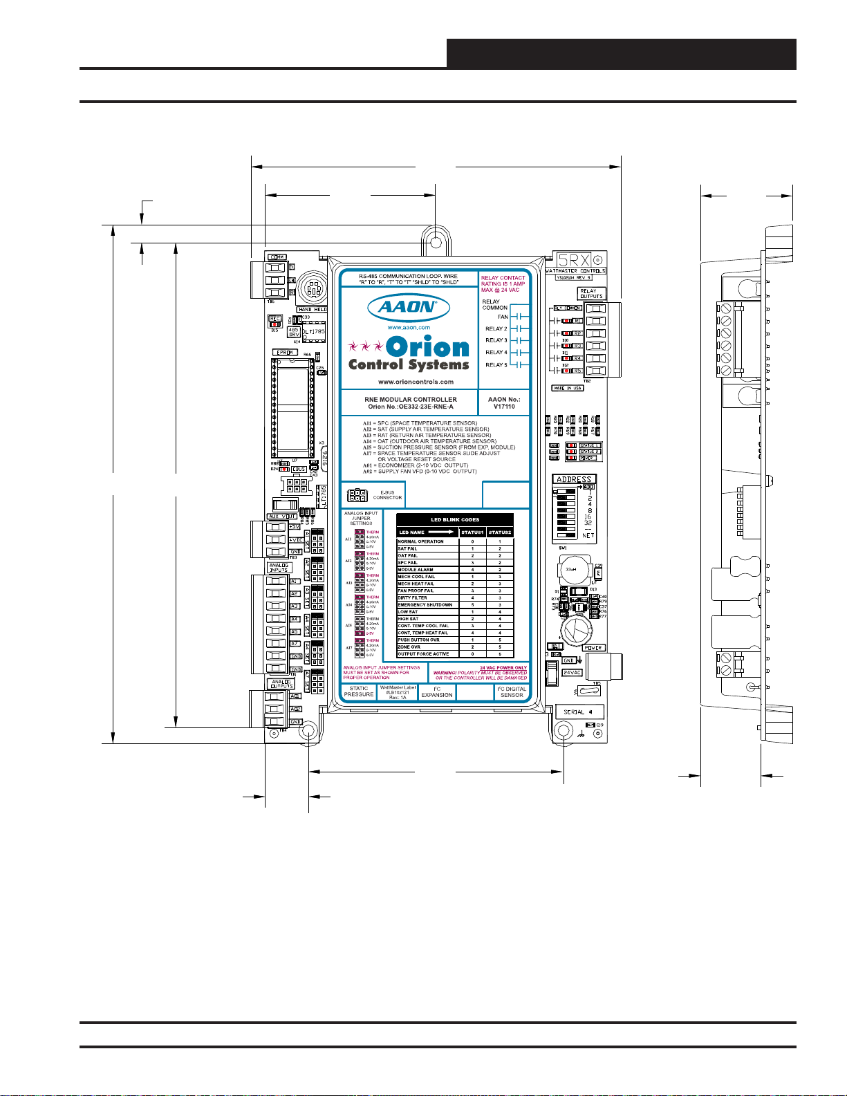
RNE Modular Controller Dimensions
5.985.98
8.388.38
0.290.29
7.837.83
2.752.75
1.49
4.104.10
0.700.70
Figure 1: OE332-23E-RNE – RNE Modular Controller Dimensions
OBSERVE
WARNING
POLARITY
0.980.98
RNE Modular Controller Field Technical Guide
13
Page 14
OVERVIEW
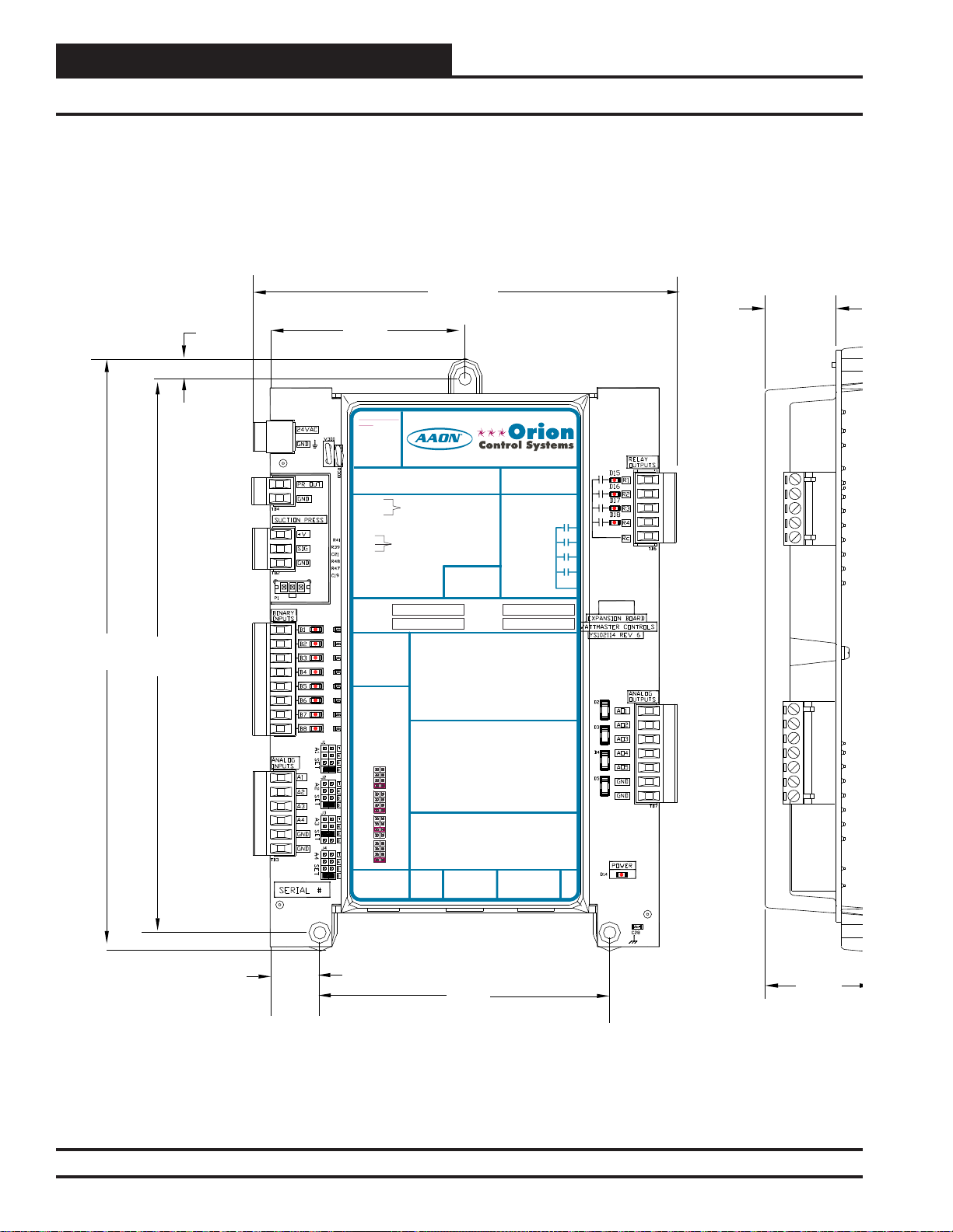
VCM-X Expansion Module for RNE Dimensions
5.98
2.75
24 VAC POWER
24 VAC POWER ONLY
ONLY
WARNING! POLARITYMUST BE
WARNING!
OBSERVED OR THE BOARD
POLARITY
WILL BE DAMAGED
MUST BE
OBSERVED OR
THE BOARD
WILL BE
DAMAGED
VCM-X Expansion Module
Orion No.:OE333-23-EM
OE333-23-EM-A VCM-X EXPANSION MODULE
PR OUT
TO VCM-X INPUT
GND
TERMINALS AI5 & GND
PR OUT
TO VCM-X INPUT
GND
TERMINALS AI5 & GND
SUCTION PRESSURE
+V
TRANSDUCER CONNECTION
SIG
FOR HVAC UNITS WITHOUT
GND
DIGITALCOMPRESSOR
SUCTION PRESSURE
+V
TRANSDUCER CONNECTION
SIG
FOR HVAC UNITS WITHOUT
GND
DIGITALCOMPRESSOR
RELAY 1 = RELAY 3 =
RELAY 2 = RELAY 4 =
RELAY 1 = RELAY 3 =
IT IS SUGGESTED
THATYOU WRITE THE
DESCRIPTION OF
RELAY 2 = RELAY 4 =
THE RELAYOUTPUTS
YOUARE USING IN
THE BOXES
IT IS SUGGESTED
PROVIDEDABOVE
THATYOU WRITE THE
WITHA PERMANENT
DESCRIPTION OF
MARKER (SHARPIE®)
THE RELAYOUTPUTS
YOUARE USING IN
THE BOXES
PROVIDEDABOVE
ANALOG INPUT
WITHA PERMANENT
MARKER (SHARPIE®)
JUMPER SETTINGS
MUST BE SETAS
SHOWN FOR
PROPER
ANALOG INPUT
OPERATION
JUMPER SETTINGS
MUST BE SETAS
SHOWN FOR
ANALOG INPUT
PROPER
JUMPER
OPERATION
SETTINGS
THERM
ANALOG INPUT
4-20mA
AI1
0-10V
JUMPER
0-5V
SETTINGS
THERM
THERM
4-20mA
4-20mA
AI2
AI1
0-10V
0-10V
0-5V
0-5V
THERM
THERM
4-20mA
4-20mA
AI3
AI2
0-10V
0-10V
0-5V
0-5V
THERM
THERM
4-20mA
4-20mA
AI4
AI3
0-10V
0-10V
0-5V
0-5V
THERM
4-20mA
AI4
0-10V
I2C
0-5V
EXPANSION
I2C
WattMaster Label
EXPANSION
#LB102034-01
www.aaon.com
BI1 = EMERGENCY SHUTDOWN - N.C. INPUT
= DIRTY FILTER - N.O. INPUT
BI2
= PROOF OF FLOW - N.O. INPUT
BI3
= REMOTE FORCED OCCUPIED - N.O. INPUT
BI4
= REMOTE FORCED HEATING - N.O. INPUT
BI5
BI1 = HOOD ON - N.O. INPUT
= DIRTY FILTER - N.O. INPUT
BI2
= REMOTE FORCED COOLING - N.O. INPUT
BI6
= PROOF OF FLOW - N.O. INPUT
BI3
= HOOD ON - N.O. INPUT
BI7
= REMOTE FORCED OCCUPIED - N.O. INPUT
BI4
= REMOTE DEHUMIDIFICATION - N.O. INPUT
BI8
= REMOTE FORCED HEATING - N.O. INPUT
BI5
= REMOTE FORCED COOLING - N.O. INPUT
BI6
NOTE:
= SMOKE DETECTOR - N.C. INPUT
BI7
ALL BINARY INPUTS MUST BE 24 VAC ONLY.
= REMOTE DEHUMIDIFICATION - N.O. INPUT
BI8
AO1 = BUILDING PRESSURE CONTROL VFD OR
NOTE:
DAMPER ACTUATOR (0-10 OR 2-10 VDC)
ALL BINARY INPUTS MUST BE 24 VAC ONLY.
AO2
= MODULATING HEATING SIGNAL
(0-10 VDC OR 2-10 VDC)
AO1 = BUILDING PRESSURE CONTROL VFD OR
AO3
= MODULATING COOLING/DIGITALSCROLL
DAMPER ACTUATOR (0-10 OR 2-10 VDC)
SIGNAL (0-10 VDC, 2-10 VDC OR 1.5-5 VDC)
AO2
= MODULATING HEATING SIGNAL
AO4
= RETURN AIR DAMPERACTUATOR
(0-10 VDC OR 2-10 VDC)
(0-10 VDC)
AO3
= MODULATING COOLING/DIGITALSCROLL
AO5
= RETURN AIR BYPASS DAMPERACTUATOR
SIGNAL (0-10 VDC, 2-10 VDC OR 1.5-5 VDC)
(0-10 VDC)
AO4
= RETURN AIR DAMPERACTUATOR
GND
= GROUND FOR ANALOG OUTPUTS
(0-10 VDC)
GND
= GROUND FOR ANALOG OUTPUTS
AO5
= RETURN AIR BYPASS DAMPERACTUATOR
(0-10 VDC)
AI1 = OUTDOOR AIR RH SENSOR (0-5 VDC)
GND
= GROUND FOR ANALOG OUTPUTS
= INDOOR AIR RH SENSOR (0-5 VDC)
AI2
GND
= GROUND FOR ANALOG OUTPUTS
= ECONOMIZER FEEDBACK
I
A3
= BUILDING STATIC PRESSURE (0-5 VDC)
AI4
AI1 = OUTDOOR AIR RH SENSOR (0-5 VDC)
= GROUND FOR ANALOG INPUTS
GND
= INDOOR AIR RH SENSOR (0-5 VDC)
AI2
= GROUND FOR ANALOG INPUTS
GND
= CO2 (0-10 VDC)
AI3
= BUILDING STATIC PRESSURE (0-5 VDC)
AI4
= GROUND FOR ANALOG INPUTS
GND
= GROUND FOR ANALOG INPUTS
GND
EXPANSION
www.orioncontrols.com
I2C
www.orioncontrols.com
AAON No.:
RELAY CONTACT
RATING IS 1AMP
MAX @ 24 VAC
RELAY CONTACT
RATING IS 1AMP
MAX @ 24 VAC
WattMaster Label
#LB102034-01-A
EXPANSION
R69190
RELAY 1
RELAY 2
RELAY 1
RELAY 3
RELAY 2
RELAY 4
RELAY 3
RELAY
RELAY 4
COMMON
RELAY
COMMON
Rev.: 1L
I2C
8.38
7.83
0.29
POLARITY
WARNING
OBSERVE
0.98
VCM
0.70
4.10
Figure 2: OE333-23-EM – VCM-X Expansion Module for RNE Dimensions
14
RNE Modular Controller Field Technical Guide
1.49
Page 15
OVERVIEW
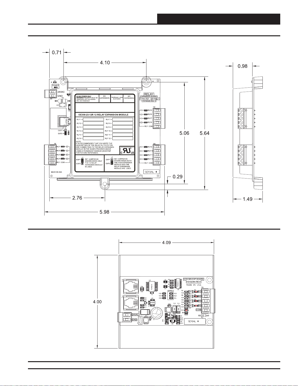
12-Relay & 4 Binary Input Expansion Module Dimensions
Figure 3: OE358-23-12R – 12-Relay Expansion Module Dimensions
Figure 4: OE356-01-BI – 4 Binary Input Expansion Module Dimensions
RNE Modular Controller Field Technical Guide
15
Page 16
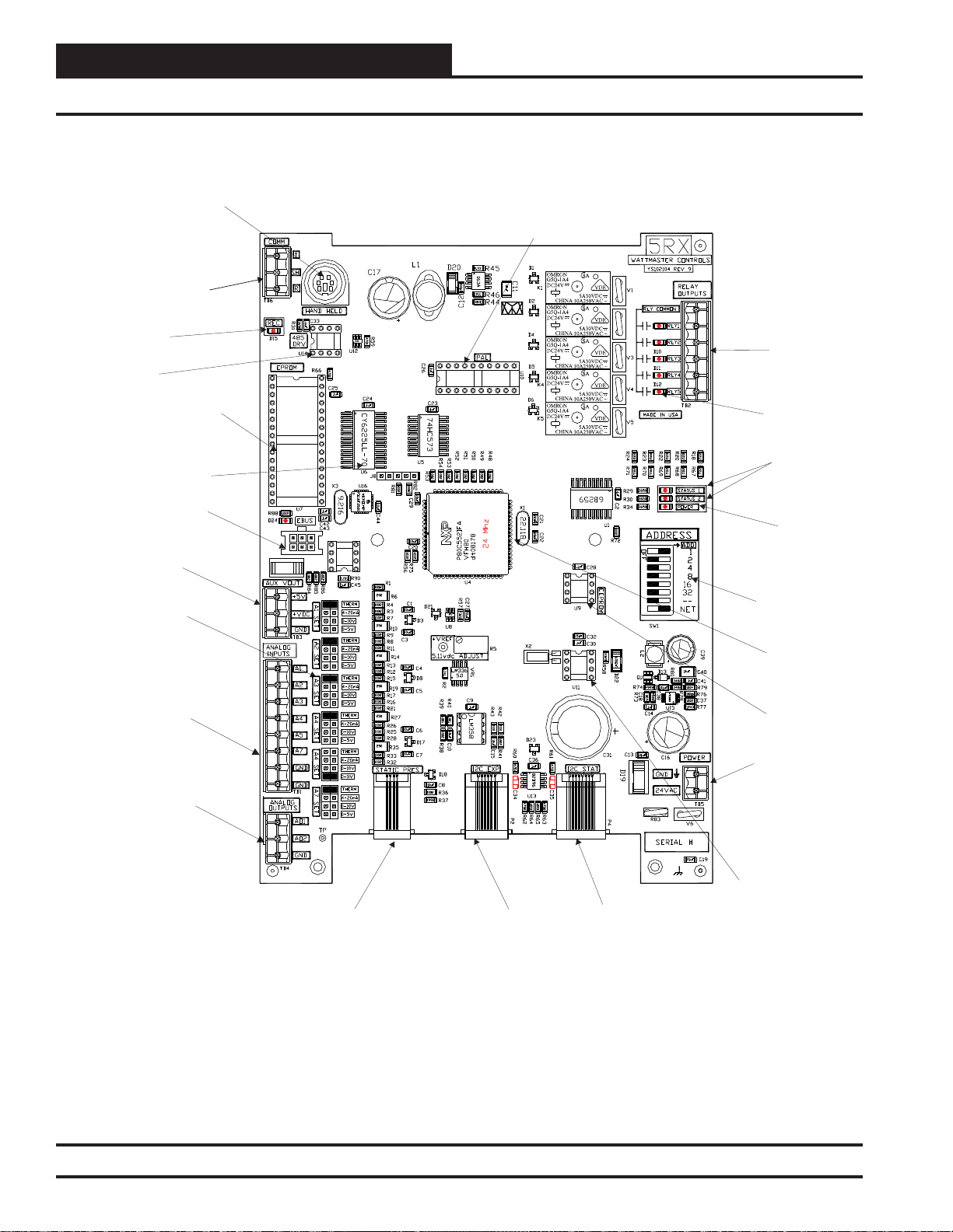
OVERVIEW
RNE Controller Component Locations
Modular Service
Tool - Mini Din
Connector
RS-485
Communications
Loop Connection
Comm
RS-485
Communications
Driver Chip
LED
Zone
Zone
PAL
Chip
Relay Output
Terminal Block
RAM Chip
E-BUS Connection
.
Auxiliary Voltage
Out Terminal Block
.
Signal Input Jumpers
For Analog Inputs-Typ.
Analog Input
Terminal Block
Analog Output
Terminal Block
EPROM
Chip
Relay Output
LED - Typ. of 5
Diagnostic
Blink Code
LEDs
Power LED
Address Switch
CPU
EEPROM
24 VAC
Power Input
Static Pressure
(Modular Connector)
Expansion Module
(Modular Connector)
(Modular Connector)
Figure 5: OE332-23E-RNE – RNE Modular Controller Component Locations
16
RNE Modular Controller Field Technical Guide
Real Time
Clock Chip
Sensor
Page 17

INSTALLATION AND WIRING
Important Wiring Considerations
General
Correct wiring of the RNE Modular Controller is the most important
factor in the overall success of the controller installation process. In
general, most RNE Controllers are factory installed and wired at the
AAON®factory . It is also possible to purchase these controllers through
your local AAON®/Orion representative for installation in the fi eld.
Some of the following information pertains to fi eld wiring and may not
apply to your installation since it was pre-wired at the factory. However ,
in the unlikely event that troubleshooting of the controller is required,
it is a good idea to be familiar with the system wiring, no matter if it
was factory or fi eld wired.
Controller Mounting
The RNE Controller is housed in a plastic enclosure. It is designed to be
mounted by using the 3 mounting holes in the enclosure base. The RNE
Controller needs to be installed in an environment which can maintain
a temperature range between -30°F and 150°F not to exceed 90% RH
levels (non-condensing). It is important to mount the controller in a
location that is free from extreme high or low temperatures, moisture,
dust, and dirt. Be careful not to damage the electronic components when
mounting the controller. See Table 1 for a list of the required operating
conditions for the RNE Controller and associated expansion modules.
Considerations
The RNE Controller and expansion modules must be connected to a
24 VAC power source of the proper size for the calculated VA load
requirements. All transformer sizing should be based on the VA rating
listed in Table 1.
Device
Control
OE332-23E-RNE
RNE Modular Controller
Voltage
24VAC 8
VA Load
Temperature
-30°F to
150°F
(Non-
Humidity
Condensing)
90% RH
WARNING: When using a single transformer to power more
than one controller or expansion module, the correct polarity must
always be maintained between the boards. Failure to observe
correct polarity will result in damage to the RNE Controller and
expansion modules.
Please carefully read and apply the following information when wiring
the RNE Controller or the Expansion Modules. See Figure 6 on page
18 for the RNE Controller wiring diagram. See Figures 17 and 18 on
pages 26 and 27 for Expansion Module Wiring.
1. All wiring is to be in accordance with local and national
electrical codes and specifi cations.
2. Minimum wire size for 24 VAC wiring should be 18-gauge.
3. Minimum wire size for all sensors should be 24-gauge.
Some sensors require 2-conductor wire and some require
3-or 4-conductor wire.
4. Be sure that all wiring connections are properly inserted
and tightened into the terminal blocks. Do not allow wire
strands to stick out and touch adjoining terminals which
could potentially cause a short circuit.
5. When communication wiring is to be used to interconnect
RNE Controllers together or to connect to other
communication devices, all wiring must be plenum-rated,
minimum 18-gauge, 2-conductor, twisted pair with shield.
WattMaster can supply communication wire that meets this
specifi cation and is color coded for the network or local
loop. Please consult your WattMaster distributor for
information. If desired, Belden #82760 or equivalent wire
may also be used.
6. Before applying power to the RNE Controller, be sure to
recheck all wiring connections and terminations
thoroughly.
OE333-23-EM
VCM-X Expansion Module
OE358-23-12R
12 Relay Expansion
Module
OE356-01-BI
4 Binary Expansion
Module
24VAC 10
24VAC 15
24VAC 5
-30°F to
150°F
-30°F to
150°F
-30°F to
150°F
90% RH
90% RH
90% RH
Table 1: Voltage and Environment Requirements
RNE Modular Controller Field Technical Guide
17
Page 18
INSTALLATION AND WIRING
RNE Controller Wiring
For Stand Alone Applications,
Connect To System Manager. For Network
Applications Connect To Next Controller And/Or
MiniLink PD On Local Loop.
Local Loop
RS-485
9600 Baud
All Comm Loop Wiring Is
T to T, R to R & SHLD to SHLD
Straight Thru
RNE Controller
Zone
Zone
Note:
All Relay Outputs Are Normally Open
And Rated For 24 VAC Power Only.
1 Amp Maximum Load.
R - 24VAC
G - Fan ON/OFF Only
AI1 SET AI2 SET AI3 SET
AI4 SET AI5 SET AI7 SET
See Individual
Component Wiring
Diagrams For Detailed
Wiring Of Analog Inputs
And Outputs
Jumpers
Splice If Required
OE271
Static Pressure
Transducer
Connect To Digital Room Sensor And/Or
Connect To
Expansion Module(s)
(When Used)
Digital CO Sensor
Relay Output Contacts
R2 Through R5 May Be UserConfigured For The Following:
1 - Heating Stages
2 - Cooling Stages
3 - Warm-up Mode Command (VAV Boxes)
4 - Reversing Valve (Air To Air Heat Pumps)
5 - Reheat Control (Dehumidification)
6 - Exhaust Fan Interlock
7 - Preheater For Low Ambient Protection
8 - Alarm
9 - Override
10 - Occupied
11 - OA Damper
12 - Heat Wheel
13 - Emergency Heat
Note: A Total Of 20 Relays Are Available By
Adding Relay Expansion Modules. All
Expansion Module Relay Outputs Are User
Configurable As Listed Above.
GND
24VAC
Size Transformer For Correct
Total Load.
RNE Controller = 8 VA
2
Warning:
24 VAC Must Be Connected So That All Ground
Wires Remain Common. Failure To Do So Will
Result In Damage To The Controllers.
Line Voltage
Connect FRP Tubing To High Pressure
Port (Bottom Tube) and Route To Static
Pressure Pickup Probe Located In Unit
Discharge. Leave Port Marked “Lo” Open
To Atmosphere
Figure 6: OE332-23E-RNE – RNE Controller Wiring
18
RNE Modular Controller Field Technical Guide
Page 19
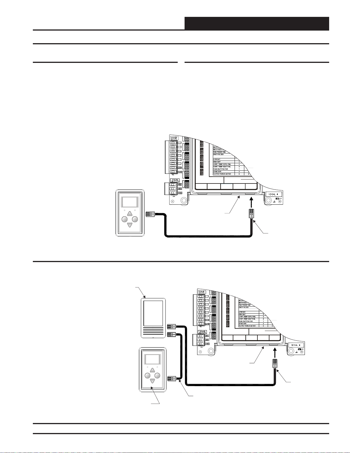
INSTALLATION AND WIRING
Digital Room Sensor & Wall Mounted Space CO2 Sensor
Digital Room Sensor
The OE217-00 Digital Room Sensor is used to sense Space Temperature and the OE217-01 Digital Room Sensor is used to sense Space
Temperature and Space Humidity. The Sensor connects to the RNE
Controller with the TSDRSC modular cable. It can be daisy-chained
with the OE256-01 CO2 Sensor for applications requiring both a room
CO2 sensor and room temperature sensor. It should be mounted at approximately 5 Ft. above the fl oor on the wall in an area that does not have
drafts or is exposed to direct sunlight. See Figure 7 for wiring details.
Note: When Only The
Is Used, It
Connects Directly To The RNE
Controller Using A Of The
Appropriate Length.
Allowed Is 160 Feet. See For
Connection When The Space CO Sensor Is
Also Used.
Digital Room Sensor
TSDRSC Cable
The Maximum Length
Figure 8
2
OVERRIDE ALARM
Display
Override
Wall Mounted Space CO2 Sensor
The OE256-01 Wall Mounted Space CO2 Sensor is used to monitor
CO2 levels in the space served by the HVAC unit. The CO2 Sensor connects to the RNE Controller with the TSDRSC modular cable. It can be
daisy-chained with the Digital Room Sensor (OE217) for applications
requiring both a room CO2 sensor and room temperature sensor. It should
be mounted at approximately 5 Ft. above the fl oor on the wall in an area
that does not have drafts or is exposed to direct sunlight. See Figure 8
for wiring details and installation notes. A Duct Mounted
can be used if desired instead of the Wall Mounted Space CO2 Sensor.
See Figure 9 on page 20 for Duct Mounted CO2 Sensor wiring details.
I1 SET
AI1
AI2 SET AI3 SET
AI2
AI3
AI4
AI5
AI4 SET AI5 SET AI7 SET
AI7
4-20mA
AI2
0-10V
0-5V
THERM
4-20mA
AI3
0-10V
0-5V
THERM
EMERGENCY SHUTDOWN
4-20mA
AI4
0-10V
0-5V
THERM
4-20mA
AI5
0-10V
0-5V
THERM
4-20mA
AI7
0-10V
0-5V
ANALOG INPUT JUMPER SETTINGS
MUST BE SETAS SHOWN FOR
PROPER OPERATION
STATIC
WattMaster Label
#LB102033-01
PRESSURE
RNE Controller
24 VAC POWER ONLY
WARNING!POLARITY MUST BE OBSERVED
OR THE CONTROLLER WILL BE DAMAGED
I2C
EXPANSION
I2C DIGITAL
SENSOR
CO
2
Sensor
Digital Room Sensor
Figure 7: OE217-00/01 – Digital Room Sensor Wiring
CO Sensor
2
Note: When a Digital Room Sensor Is
Used In Combination With The
The r Always
Sensor, CO Senso
Connects To The RNE Controller First
2
Using a TSDRSC Cable Of The
Length. The Digital Room Sensor Then
Connects To The CO Sensor With
Another Cable.
TSDRSC
2
At Least 5 Feet Above Floor. See The
C Sensor Technical GuideO
2
Wiring Details.
CO
2
Required
Mount Sensor(s)
For Further
Digital Room Sensor
OVERRIDE ALARM
Display
Override
I1 SET
AI1
AI2 SET AI3 SET
AI2
AI3
AI4
AI5
AI4 SET AI5 SET AI7 SET
AI7
RNE Controller
TSDRSC Cable
4-20mA
AI2
0-10V
0-5V
THERM
4-20mA
AI3
0-10V
0-5V
THERM
EMERGENCY SHUTDOWN
4-20mA
AI4
0-10V
0-5V
THERM
4-20mA
AI5
0-10V
0-5V
THERM
4-20mA
AI7
0-10V
0-5V
ANALOG INPUTJUMPER SETTINGS
MUSTBE SET AS SHOWN FOR
PROPER OPERATION
STATIC
WattMaster Label
#LB102033-01
PRESSURE
24 VAC POWER ONLY
WARNING!POLARITY MUST BE OBSERVED
OR THE CONTROLLER WILLBE DAMAGED
I2C
EXPANSION
TSDRSC Cable
I2C DIGITAL
SENSOR
TSDRSC Cable
Figure 8: OE256-01 – Wall Mounted Space CO2 Sensor Wiring
RNE Modular Controller Field Technical Guide
19
Page 20
OVERVIEW
Ducted Mounted CO2 Sensor
Zone
Zone
Duct Mounted CO2 Sensor
The OE256-02 CO2 Sensor is used for sensing the current CO2 level
in the HVAC unit’s return air stream. This is useful when you want an
average CO2 reading in the area served by the HVAC unit or when you
don’t want a wall mounted CO2 sensor due to sensor tampering concerns
in the space.
Note:
1.) The CO Sensor Always Connects To The RNE Controller
Using A TSDRSC Cable Of The Required Length. If Also
Using A Digital Room Sensor, Connect The Digital Room
Sensor To The C Sensor Using Another TSDRSC Cable
Of The Required Length. The Total Length Of Cable For All
Sensor Cables Combined Cannot Exceed 160 Feet.
Wall Mounted
Digital Room Sensor
OVERRIDE ALARM
Display
Override
2
O
2
TSDRSC Cable
Duct Mounted CO Sensor
2
The OE256-02 Duct Mounted Return Air CO
the OE256-01 CO2 Sensor and the WattMaster Aspiration Box Assembly .
The Duct Mounted Return Air CO
the return air duct of the HVAC unit and uses its integral aspiration box
to sample the CO
tion information in Figure 9 below for wiring and installation details.
level in the duct. See the dimensional and installa-
2
Sensor is designed to be mounted in
2
Sensor is comprised of
2
RNE Controller
RS-485 COMMUNICATION LOOP. WIRE
“R” TO “R”, “T” TO“T” “SHLD” TO “SHLD”
RS-485 COMMUNICATION LOOP. WIRE
“R” TO “R”, “T”TO “T” “SHLD” TO “SHLD”
www.orioncontrols.com
VCM-X MODULAR E-BUS CONTROLLER
Orion No.:OE332-23E-VCMX-MOD-A
OE332-23-VCMX-A VCM-X CONTROLLER
AI1 = SPC (SPACETEMPERATURE SENSOR)
AI1 = SPC (SPACETEMPERATURE SENSOR)
= SAT(SUPPLY AIR TEMPERATURE SENSOR)
AI2
AI2
= SAT(SUPPLY AIR TEMPERATURE SENSOR)
= RAT(RETURN AIR TEMPERATURE SENSOR)
AI3
AI3
= RAT(RETURN AIR TEMPERATURE SENSOR)
= OAT(OUTDOOR AIR TEMPERATURE SENSOR)
AI4
AI4
= OAT(OUTDOOR AIR TEMPERATURE SENSOR)
= SUCTION PRESSURE SENSOR (FROM EXP. MODULE)
AI5
AI5
= SUCTION PRESSURE SENSOR
= SPACETEMPERATURE SENSOR SLIDE ADJUST
AI7
AI7
= SPACETEMPERATURE SENSOR SLIDE ADJUST
OR VOLTAGE RESETSOURCE
OR VOLTAGE RESETSOURCE
A01
= ECONOMIZER (2-10 VDC OUTPUT)
A01
= ECONOMIZER (2-10 VDC OUTPUT)
A02
= SUPPLYFAN VFD (0-10 VDC OUTPUT)
A02
= SUPPLYFAN VFD (0-10 VDC OUTPUT)
E-BUS
CONNECTOR
ANALOG INPUT
ANALOG INPUT
JUMPER
JUMPER
SETTINGS
SETTINGS
THERM
LED NAME STATUS1 STATUS2
THERM
4-20mA
4-20mA
AI1
AI1
0-10V
NORMALOPERATION 0 1
0-10V
0-5V
0-5V
SAT FAIL 1 2
THERM
THERM
OAT FAIL 2 2
4-20mA
4-20mA
AI2
AI2
AI3
AI4
AI5
AI5
AI7
ANALOG INPUTJUMPER SETTINGS
ANALOG INPUTJUMPER SETTINGS
MUSTBE SET AS SHOWN FOR
MUSTBE SET AS SHOWN FOR
PROPER OPERATION
PROPER OPERATION
PRESSURE
PRESSURE
AI3
AI4
AI7
STATIC
STATIC
0-10V
0-10V
0-5V
0-5V
THERM
THERM
4-20mA
4-20mA
0-10V
0-10V
0-5V
0-5V
THERM
THERM
4-20mA
4-20mA
0-10V
0-10V
0-5V
0-5V
THERM
THERM
4-20mA
4-20mA
0-10V
0-10V
0-5V
0-5V
THERM
THERM
4-20mA
4-20mA
0-10V
0-10V
0-5V
0-5V
WattMaster Label
WattMaster Label
#LB102073-01-A
#LB102033-01
SPC FAIL 3 2
MODULEA LARM 4 2
MECH COOL FAIL 1 3
MECHHEAT FAIL 2 3
FAN PROOFFA IL 3 3
DIRTY FILTER 4 3
EMERGENCYSH UTDOWN 5 3
LOW SAT 1 4
HIGH SAT 2 4
CONT.TEMP COOL FAIL 3 4
CONT.TEMP HEAT FA IL 4 4
PUSH BUTTON OVR 1 5
ZONE OVR 2 5
OUTPUTFORCE ACTIVE 0 6
EXPANSION
EXPANSION
Rev.: 1A
RELAYCONTACT
RATING IS 1AMP
RELAYCONTACT
MAX @ 24 VAC
RATING IS 1AMP
MAX @ 24 VAC
RELAY
COMMON
RELAY
COMMON
FAN
FAN
RELAY2
RELAY2
RELAY3
RELAY3
RELAY4
RELAY4
RELAY5
RELAY5
AAON No.:
V07150
LED BLINK CODES
24 VAC POWER ONLY
24 VAC POWER ONLY
WARNING!POLARITY MUST BE OBSERVED
WARNING!POLARITY MUST BE OBSERVED
OR THE CONTROLLER WILLBE DAMAGED
OR THE CONTROLLER WILLBE DAMAGED
2
2
IC
IC
2
2
IC DIGITAL
IC DIGITAL
SENSOR
SENSOR
OBSERVE
POLARITY
WARNING
Connection Of Wall
Mounted
Digital Room Sensor
(When Used)
Figure 9: OE256-02 - Duct Mounted CO2 Sensor Wiring
20
RNE Modular Controller Field Technical Guide
TSDRSC Cable
Page 21
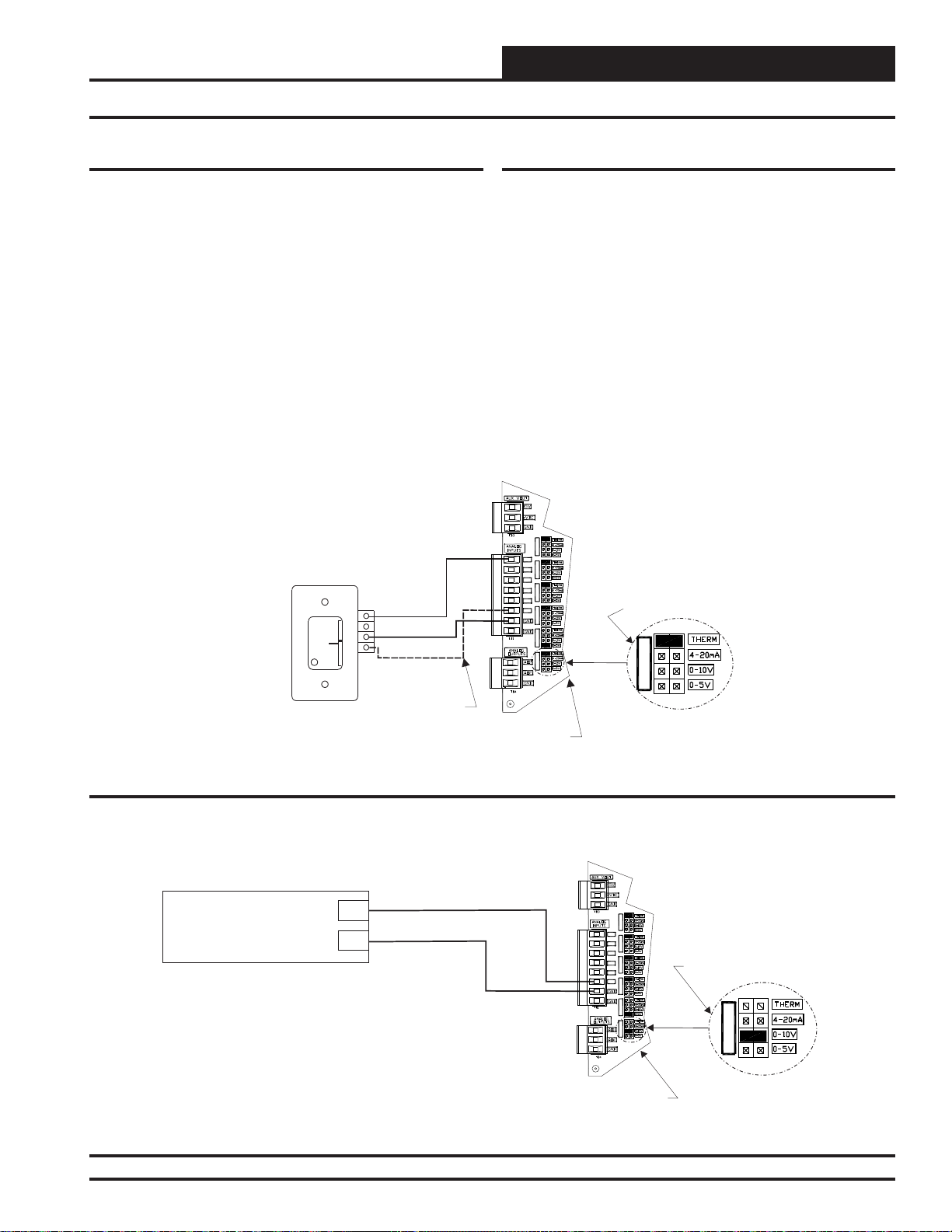
INSTALLATION AND WIRING
Remote Supply Air
Temperature Reset Signal
(By Others)
0-5 VDC or 0-10 VDC Signal
GND
Note:
Either The Slide Offset Option For The Space Temperature
Sensor Or The Remote Supply Air Temperature Reset
Signal Option (By Others) May Be Connected To AI7 On
The RNE Controller. Only One Option Is Allowed, Not Both.
AI7
GND
RNE Controller
AI1
AI1 SET
AI2 SET AI3 SET
AI4 SET AI5 SET AI7 SET
AI2
AI3
AI4
AI5
AI7
Regardless of Whether the Remote
SAT Reset Signal Has Been
Configured For 0-5 or 0-10 VDC,
Jumper Must Be Set For 0-10V
AI7 SET
Remote SAT Reset Signal
Space Temperature Sensor
The OE210, OE211, OE212, OE213 Space Temperature Sensor is typically used for constant volume HVAC unit applications controlling one
zone. The Space T emperature Sensor is a 10K T ype III thermistor sensor
and should be mounted approximately 5 feet above the fl oor in the space
that is to be controlled. The Space Temperature Sensor is available as a
sensor only, sensor with override button, sensor with slide adjust, and
sensor with slide adjust and override confi gurations.
When the Remote Supply Air T emperature Reset Signal option is needed,
the Slide Offset option on the Room Sensor cannot be used. Only one
of these options may be used on the RNE Controller.
See Figure 10 below for complete Space Temperature Sensor wiring
details.
Note:
Either The Slide Offset Option For The Space
Temperature Sensor Or The Remote Supply
Air Temperature Reset Signal Option (By
Others) May Be Connected To An AI7 On
The RNE Controller. Only One Option Is
Allowed, Not Both.
AI1
Space Temperature Sensor
TMP
W
A
R
M
GND
E
R
C
O
O
OVR
L
E
R
AUX
Wire Required For
Sensors With Slide
Adjust Option Only
AI7
GND
Remote SAT Reset Signal
A Remote Supply Air T emperature Reset Signal can be connected to AI7
for applications requiring remote reset of the Supply Air Temperature
Setpoint.
When the Slide Offset option on the Room Sensor is used, the Remote
Supply Air Temperature Reset Signal cannot be used. Only one of these
options may be used on the RNE Controller.
The RNE Controller can accept either a 0-5 VDC signal or a 0-10 VDC
signal on this input.
See Figure 11 below for complete Remote SAT Reset Signal wiring
details.
AI1 SET AI2 SET AI3 SET
AI1
AI2
AI3
AI4
AI5
AI4 SET AI5 SET AI7 SET
AI7
Set Jumper For THERM
When Space Sensor Slide
Adjust Is Wired To AI7
AI7 SET
Figure 10: OE210, OE211, OE212, OE213 – Space Temperature Sensor Wiring
Figure 11: Remote Supply Air Temperature Reset Signal Wiring
RNE Controller
RNE Modular Controller Field Technical Guide
21
Page 22
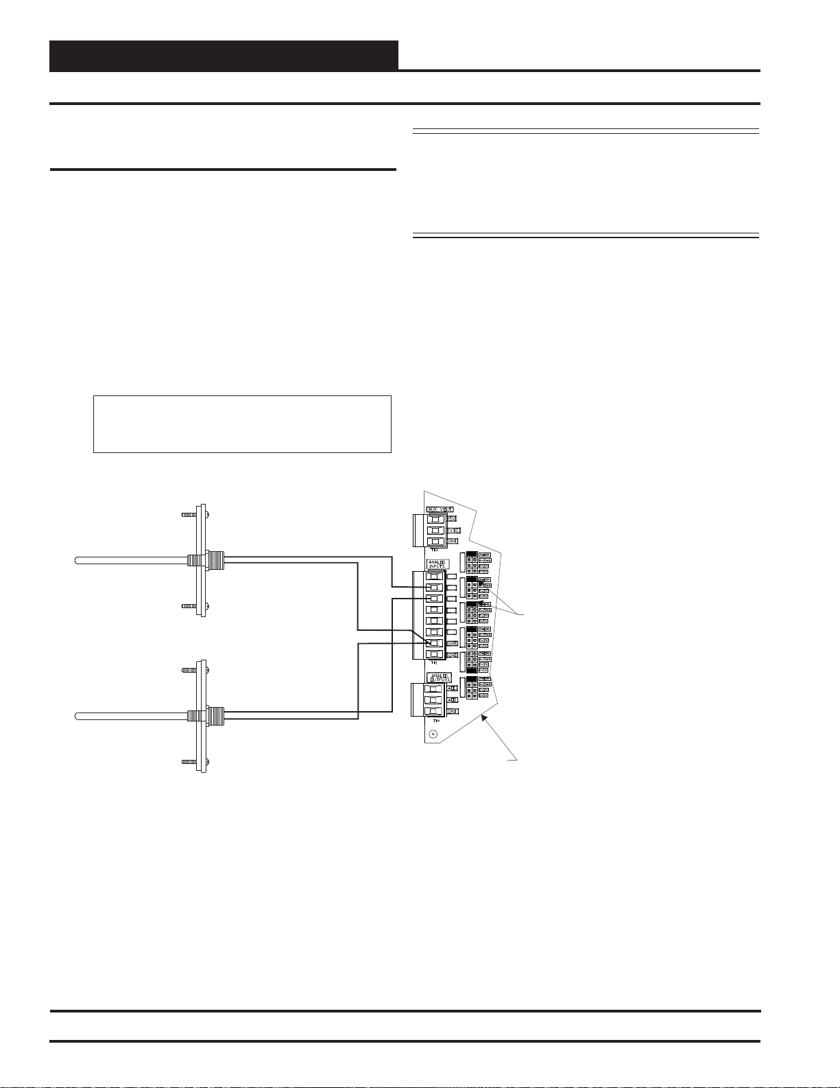
INSTALLATION AND WIRING
SAT & RAT Sensor Wiring
Zone
Zone
Supply Air & Return Air Temperature
Sensor
The OE231 Supply Air & Return Air Temperature Sensors must be
wired as shown in Figure 12 below for proper operation. The Supply
Air & Return Air Temperature Sensors are 10K Type III thermistor
sensors. The Supply Air Temperature Sensor should be mounted in the
unit discharge plenum or in the supply air duct. The Return Air Temperature Sensor should be mounted in the return air duct. If the system
has a Zoning Bypass Damper installed, be sure the return air sensor is
located upstream of the bypass duct connection.
Note: The Supply Air Temperature Sensor Always
Wires To The AI2 Input On The RNE Controller Unless
Using The MODGAS II And/Or MHGRV II Controllers
As Stand-Alone.
Supply Air Temperature Sensor
NOTE: If your AAON® HVAC unit is using the AAON®
MODGAS-X Controller and/or the AAON® MHGRVX Controller, the Supply Air Temperature Sensor must
always be connected to the RNE Controller unless you
are using the AAON® MODGAS-X and/or AAON®
MHGRV-X Controllers as stand-alone.
Mount In HVAC
Unit Supply
Air Duct
Return Air Temperature Sensor
Mount In HVAC
Unit Return
Air Duct
GND
GND
AI2
AI3
RNE Controller
AI1 SET AI2 SET AI3 SET
AI1
AI2
AI3
AI4
AI5
AI4 SET AI5 SET AI7 SET
AI7
Be Sure The Jumper Is Set For THERM
On AI2 & AI3 For Supply
& Return Air Temperature Sensors
When Used
Figure 12: OE230 / OE231 – Supply Air and Return Air Temperature Sensor Wiring
22
RNE Modular Controller Field Technical Guide
Page 23
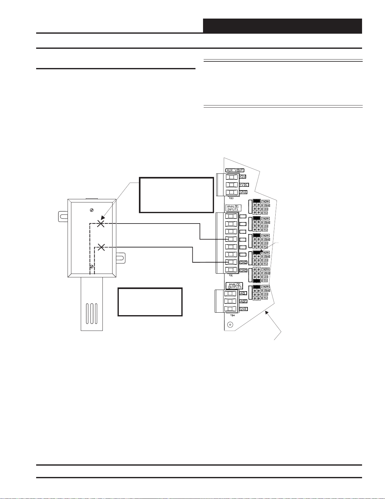
INSTALLATION AND WIRING
OAT Sensor Wiring
Outdoor Air Temperature Sensor
The OE250 Outdoor Air Temperature Sensor must be wired as shown
in Figure 13 below for proper operation of the RNE Controller. The
Outdoor Air Temperature Sensor is a 10K Type III thermistor sensor.
The sensor should be mounted in the upright position as shown in an
area that is protected from the elements and direct sunlight. Be sure to
make the wiring splices inside of the Outdoor Air Temperature Sensor
weather-tight enclosure.
Outdoor Air
Temperature Sensor
Make Splice Connections
Inside Sensor Enclosure
As Shown. Seal All Conduit
Fittings With Silicone
Sealant
CAUTION: Be sure to mount the Outdoor Air Temperature
Sensor in an area that is not exposed to direct sunlight. The shaded
area under the HVAC unit rain hood is normally a good location.
Unused conduit opening(s) must have closure plugs installed and
must be coated with sealing compound to provide a rain-tight seal.
Water can damage the sensor.
AI1 SET AI2 SET AI3 SET
AI1
AI2
AI4
GND
AI3
AI4
AI5
AI4 SET AI5 SET AI7 SET
AI7
Be Sure Jumper Is Set
For THERM
On AI4 For Outdoor
Air Temperature Sensor
Mount Sensor Outdoors
In Shaded Protected
Area & In Upright
Position As Shown
Figure 13: OE250 – Outdoor Air Temperature Sensor Wiring
RNE Controller
RNE Modular Controller Field Technical Guide
23
Page 24
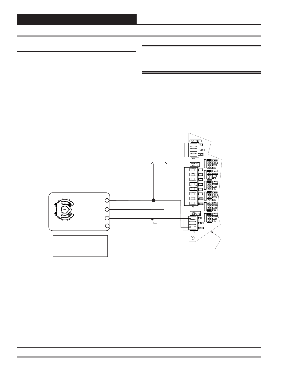
INSTALLATION AND WIRING
24 VAC Power Source
Sized For Actuator VA Load
24 VAC
GND
2-10 VDC
Output
RNE Controller
GND
AO1
AI1
AI1 SET AI2 SET AI3 SET
AI4 SET AI5 SET AI7 SET
AI2
AI3
AI4
AI5
AI7
Economizer Damper Actuator
(Belimo Actuator Shown)
Y1 3
+ 2
COM - 1
Belimo Actuator Wiring
Shown. Consult Factory For
Other Manufacturer Wiring
Instructions
Economizer Feedback 5
NOTE: For Economizer
Actuator Feedback Signal,
See Wiring For The
VCM-X Expansion Module.
AI3
Economizer Damper Actuator Wiring
Zone
Zone
Economizer Damper Actuator
The Economizer Damper Actuator signal voltage output is a 2-10 VDC
output. This signal output is used by the RNE Controller to modulate
the Economizer Damper Actuator in order to control the amount of
Outdoor Air delivered to the HVAC unit for Free Cooling and/or Indoor
Air Quality requirements. See Figure 14 for detailed wiring.
WARNING: It is very important to be certain that all wiring is
correct as shown in the wiring diagram below. Failure to observe
the correct polarity will result in damage to the actuator or RNE
Controller.
Figure 14: Economizer Damper Actuator Wiring
24
RNE Modular Controller Field Technical Guide
Page 25
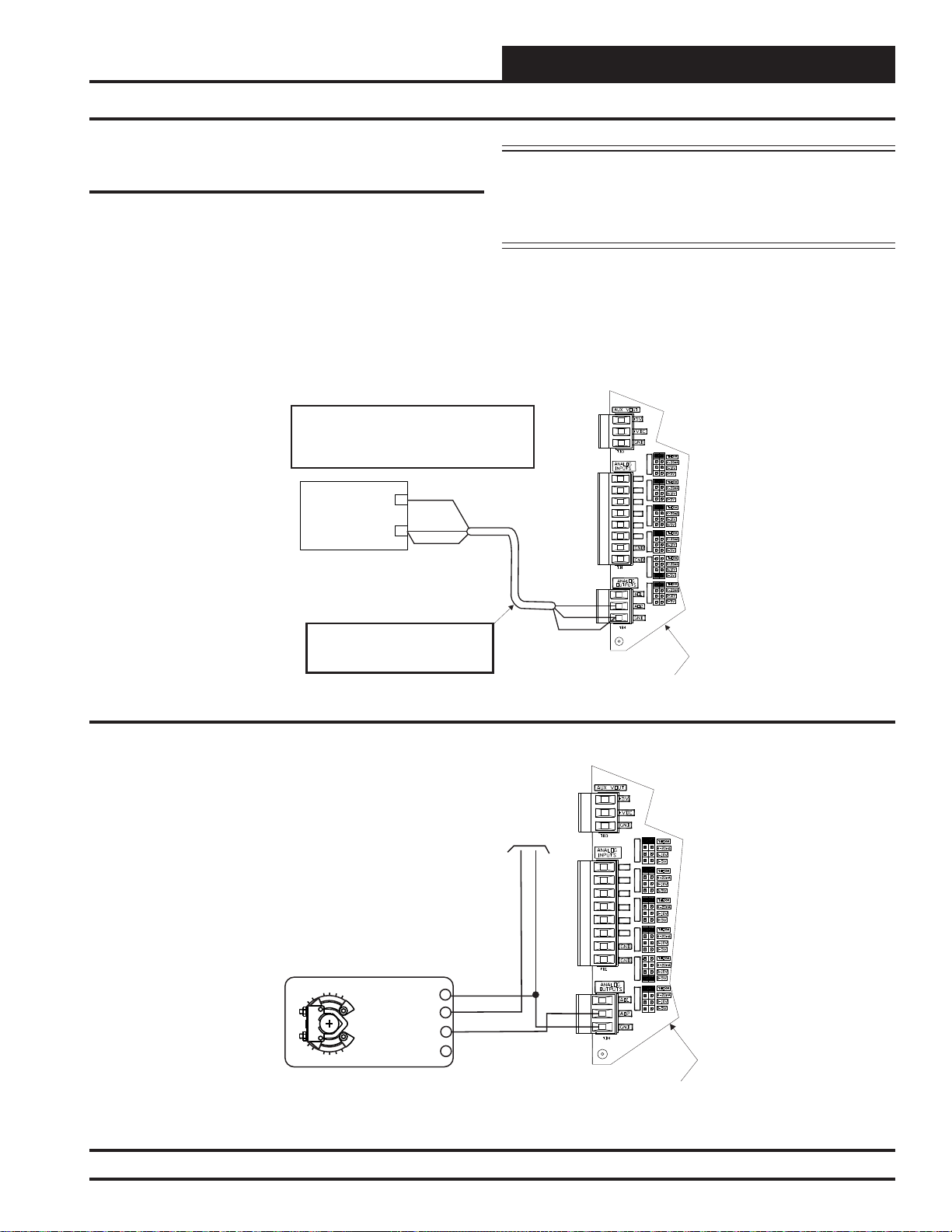
INSTALLATION AND WIRING
+
_
3 (Y)
5 (U)
2 (+)
1 (-)
Supply Fan VFD Signal and Zoning Bypass Damper Actuator
Supply Fan VFD Signal or Zoning
Bypass Damper Actuator Signal
The Supply Fan VFD or Zoning Bypass Damper Actuator Signal is a
0-10 VDC output. This signal output can be connected to the Supply
Fan Variable Frequency Drive to modulate the Supply Fan speed and
control Duct Static Pressure utilizing the Duct Static Pressure Sensor
connected to the RNE Controller. Alternatively, it can be connected to a
Zoning Bypass Damper Actuator that will modulate the Zoning Bypass
Damper Actuator to control Duct Static Pressure utilizing the Duct Static
Pressure Sensor connected to the RNE Controller. A Duct Static Pressure
Sensor must be connected in order for the VFD or Zoning Bypass Damper
Actuator to operate. See Figures 15 and 16 below for detailed wiring.
Caution:
The VFD Unit Must Be Configured For 0-10 VDC Input.
The Input Resistance At The VFD Must Not Be Less
Than 1000 Ohms When Measured At The VFD
Terminals WithAll Input Wires Removed.
0-10VDC Input From AO2
GND
Shield
Supply Fan Variable Frequency Drive
(By Others)
Note:
Wire To The VFD Using 18 GA Minimum 2
Conducter Twisted Pair With Shield Cable.
Wire Shield To GND As Shown
CAUTION: Variable Frequency Drive units can cause large
transient noise spikes which can cause interference to be propagated
on other electronic equipment. Use shielded wire wherever possible
and route all sensor and controller wiring away from the Variable
Frequency Drive and the HVAC Unit electrical wiring.
AI1 SET
AI1
AI2 SET AI3 SET
AI2
AI3
AI4
AI5
AI4 SET AI5 SET AI7 SET
AI7
AO2
GND
Shield
RNE Controller
Figure 15: Supply Fan VFD Wiring
24 VAC Power Source
Sized For Actuator VA Load
Bypass Damper Actuator
(Belimo Actuator Shown)
Figure 16: Zoning Bypass Damper Actuator Wiring
Belimo Actuator Wiring Shown.
Consult Factory For Other
Manufacturer Wiring Instructions.
GND
24 VAC
0-10 VDC
AO2
GND
AI1 SET AI2 SET AI3 SET
AI1
AI2
AI3
AI4
AI5
AI4 SET AI5 SET AI7 SET
AI7
RNE Controller
RNE Modular Controller Field Technical Guide
25
Page 26
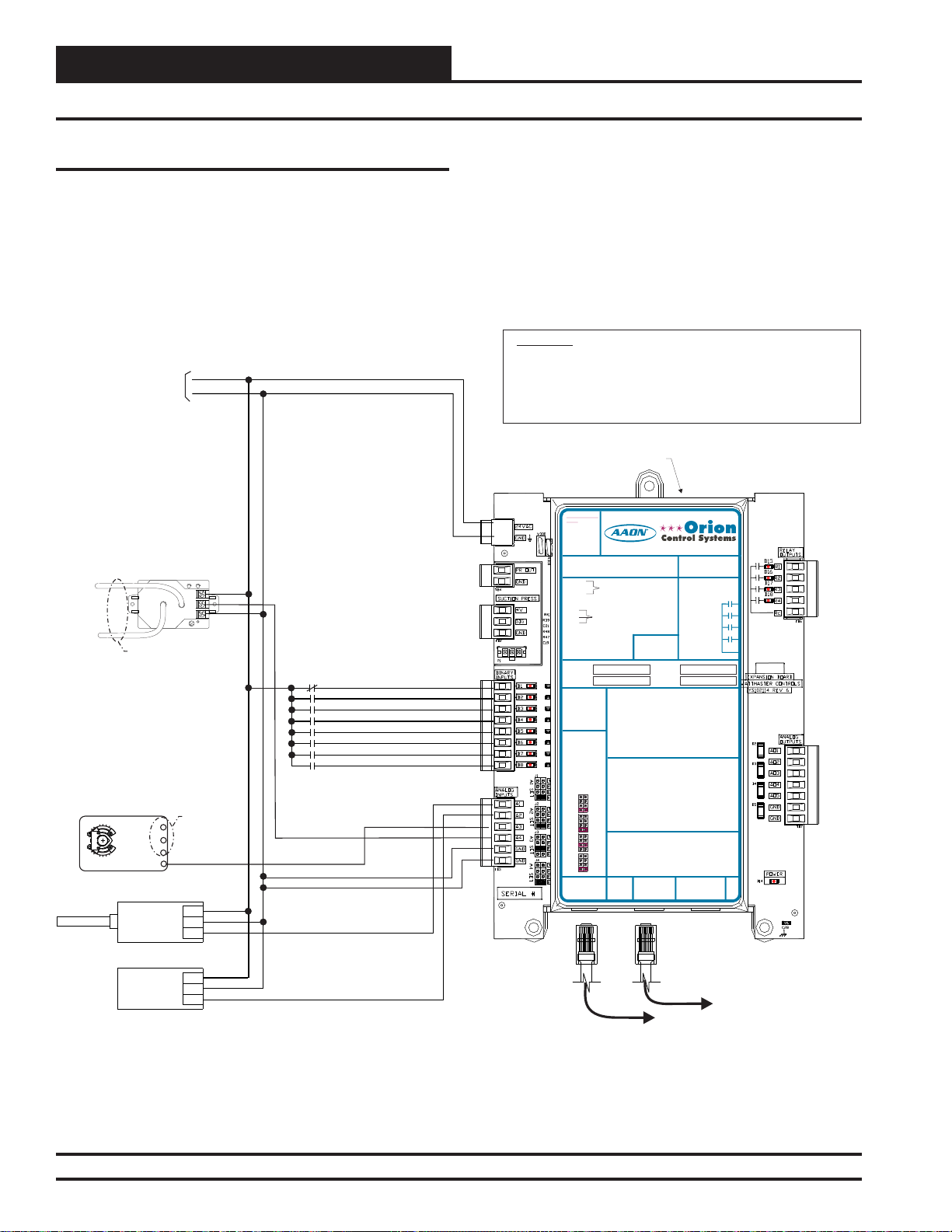
Zone
Y1 3
+ 2
COM - 1
Economizer Feedback 5
INSTALLATION AND WIRING
Zone
VCM-X Expansion Module Input Wiring for the RNE Controller
VCM-X Expansion Module for RNE
Three different Expansion Modules are available for use with the RNE
Controller to provide additional inputs and outputs beyond those found
on the RNE Controller.
The VCM-X Expansion Module ( OE333-23-EM) provides 8 Binary
Inputs, 4 Analog Inputs, 4 Relay Outputs, and 5 Analog Outputs. See
Figures 17 and 18 for complete wiring details.
+
LOW
See Economizer
Actuator Wiring
AO1
Controller
GND
0-5V
VIN
GND
24 VAC
+
+
-
For RNE
GND
EXC
OUT
COM
Emergency Shutdown - N.C. Contact
Dirty Filter - N.O. Contact
Proof Of Flow - N.O. Contact
Remote Forced Occupied - N.O. Contact
Remote Forced Heating - N.O. Contact
Remote Forced Cooling - N.O. Contact
Hood On - N.O. Contact
Remote Forced Dehumidification
N.O. Contact
10 VA Minimum Power
Required For
VCM-X Expansion Module
Building Pressure
Plastic Tubing To Building
Pressure Sensing Locations
Economizer Damper Actuator
(Belimo Actuator Shown)
Outdoor Air
Humidity Sensor
VAC OR DC
Indoor Air
Humidity Sensor
VOUT (0-5V)
Transducer
HIGH
The VCM-X Expansion Module can be used in conjunction with the
12-Relay Expansion Module (OE358-23-12R-A).
The 4 Binary Input Expansion Module (OE356-01-BI) can be used in
place of the VCM-X Expansion Module if your system does not need
any other inputs or outputs.
WARNING!!
Observe Polarity! All boards must be wired with GND-to-GND and
24VAC-to-24VAC. Failure to observe polarity will result in damage to one
or more of the boards. Expansion Modules must be wired in such a way
that the expansion modules and the controller are always powered
together. Loss of power to the expansion module will cause the controller
to become inoperative until power is restored to the expansion module.
VCM-X Expansion Module
24 VAC POWER
POLARITY
WARNING
OBSERVE
PR OUT
GND
B 1I
B 2I
B 3I
B 4I
B 5I
B 6I
B 7I
BI8
AI1
AI2
AI3
AI4
GND
GND
Modular Cable
Connect To Next Expansion
Board (When Used)
ITIS SUGGESTED
THATYOU WRITE THE
DESCRIPTION OF
THE RELAYOUTPUTS
YOUARE USING IN
THE BOXES
PROVIDEDABOVE
WITHA PERMANENT
MARKER (SHARPIE®)
JUMPER SETTINGS
24 VAC POWER ONLY
ONLY
WARNING!POLARITY MUST BE
WARNING!
OBSERVED OR THE BOARD
POLARITY
WILL BE DAMAGED
MUST BE
OBSERVED OR
THE BOARD
WILL BE
DAMAGED
VCM-X Expansion Module
Orion No.:OE333-23-EM
OE333-23-EM-AVCM-X EXPANSION MODULE
PR OUT
GND
SUCTION PRESSURE
+V
TRANSDUCER CONNECTION
SIG
FOR HVAC UNITS WITHOUT
GND
DIGITALCOMPRESSOR
SUCTION PRESSURE
+V
TRANSDUCER CONNECTION
SIG
FOR HVAC UNITS WITHOUT
GND
DIGITALCOMPRESSOR
RELAY1 = RELAY 3 =
RELAY2 = RELAY 4 =
RELAY1 = RELAY3 =
RELAY2 = RELAY4 =
ITIS SUGGESTED
THATYOU WRITE THE
DESCRIPTION OF
THE RELAYOUTPUTS
YOUARE USING IN
THE BOXES
PROVIDEDABOVE
ANALOG INPUT
WITHA PERMANENT
MARKER (SHARPIE®)
MUST BE SETAS
SHOWN FOR
PROPER
ANALOG INPUT
OPERATION
JUMPER SETTINGS
MUST BE SETAS
SHOWN FOR
ANALOG INPUT
PROPER
JUMPER
OPERATION
SETTINGS
THERM
4-20mA
ANALOG INPUT
AI1
0-10V
JUMPER
0-5V
SETTINGS
THERM
THERM
4-20mA
4-20mA
AI2
AI1
0-10V
0-10V
0-5V
0-5V
THERM
THERM
4-20mA
4-20mA
AI3
AI2
0-10V
0-10V
0-5V
0-5V
THERM
THERM
4-20mA
4-20mA
AI4
AI3
0-10V
0-10V
0-5V
0-5V
THERM
4-20mA
AI4
0-10V
I2C
0-5V
EXPANSION
I2C
WattMaster Label
EXPANSION
#LB102034-01
www.aaon.com
TO VCM-X INPUT
TERMINALS AI5 & GND
TO VCM-X INPUT
TERMINALS AI5 & GND
BI1 = EMERGENCY SHUTDOWN - N.C. INPUT
= DIRTY FILTER - N.O. INPUT
BI2
= PROOF OF FLOW - N.O. INPUT
BI3
= REMOTE FORCED OCCUPIED - N.O. INPUT
BI4
= REMOTE FORCED HEATING - N.O. INPUT
BI5
BI1 = HOOD ON - N.O. INPUT
= REMOTE FORCED COOLING - N.O. INPUT
BI6
= DIRTY FILTER - N.O. INPUT
BI2
= HOOD ON - N.O. INPUT
BI7
= PROOF OF FLOW - N.O. INPUT
BI3
= REMOTE DEHUMIDIFICATION - N.O. INPUT
BI8
= REMOTE FORCED OCCUPIED - N.O. INPUT
BI4
= REMOTE FORCED HEATING - N.O. INPUT
BI5
NOTE:
= REMOTE FORCED COOLING - N.O. INPUT
BI6
ALL BINARYINPUTS MUST BE 24 VAC ONLY.
= SMOKE DETECTOR - N.C. INPUT
BI7
= REMOTE DEHUMIDIFICATION - N.O. INPUT
BI8
AO1 = BUILDING PRESSURE CONTROL VFD OR
NOTE:
DAMPER ACTUATOR (0-10 OR 2-10 VDC)
ALL BINARYINPUTS MUST BE 24 VAC ONLY.
AO2
= MODULATING HEATING SIGNAL
(0-10 VDC OR 2-10 VDC)
AO1 = BUILDING PRESSURE CONTROL VFD OR
AO3
= MODULATING COOLING/DIGITALSCROLL
DAMPER ACTUATOR (0-10 OR 2-10 VDC)
SIGNAL (0-10 VDC, 2-10 VDC OR 1.5-5 VDC)
AO2
= MODULATING HEATING SIGNAL
AO4
= RETURN AIR DAMPERACTUATOR
(0-10 VDC OR 2-10 VDC)
(0-10 VDC)
AO3
= MODULATING COOLING/DIGITALSCROLL
AO5
= RETURN AIR BYPASS DAMPERACTUATOR
SIGNAL (0-10 VDC, 2-10 VDC OR 1.5-5 VDC)
(0-10 VDC)
AO4
= RETURN AIR DAMPERACTUATOR
GND
= GROUND FOR ANALOG OUTPUTS
(0-10 VDC)
= GROUND FOR ANALOG OUTPUTS
GND
AO5
= RETURN AIR BYPASS DAMPERACTUATOR
(0-10 VDC)
AI1 = OUTDOOR AIR RH SENSOR (0-5 VDC)
GND
= GROUND FOR ANALOG OUTPUTS
AI2
= INDOOR AIR RH SENSOR (0-5 VDC)
GND
= GROUND FOR ANALOG OUTPUTS
A3
= ECONOMIZER FEEDBACK
I
AI4
= BUILDING STATIC PRESSURE (0-5 VDC)
AI1 = OUTDOOR AIR RH SENSOR (0-5 VDC)
GND
= GROUND FOR ANALOG INPUTS
= INDOOR AIR RH SENSOR (0-5 VDC)
AI2
GND
= GROUND FOR ANALOG INPUTS
= CO2 (0-10 VDC)
AI3
= BUILDING STATIC PRESSURE (0-5 VDC)
AI4
= GROUND FOR ANALOG INPUTS
GND
= GROUND FOR ANALOG INPUTS
GND
I2C
EXPANSION
www.orioncontrols.com
AAON No.:
www.orioncontrols.com
RELAYCONTACT
RATING IS 1AMP
MAX @ 24 VAC
RELAYCONTACT
RATING IS 1AMP
MAX @ 24 VAC
WattMaster Label
#LB102034-01-A
R69190
RELAY1
RELAY2
RELAY1
RELAY3
RELAY2
RELAY4
RELAY3
RELAY
RELAY4
COMMON
RELAY
COMMON
Rev.: 1L
I2C
EXPANSION
VCM
Modular Cable
Connect To RNE
Controller
Figure 17: OE333-23-EM – VCM-X Expansion Module for RNE Input Wiring
26
RNE Modular Controller Field Technical Guide
Page 27
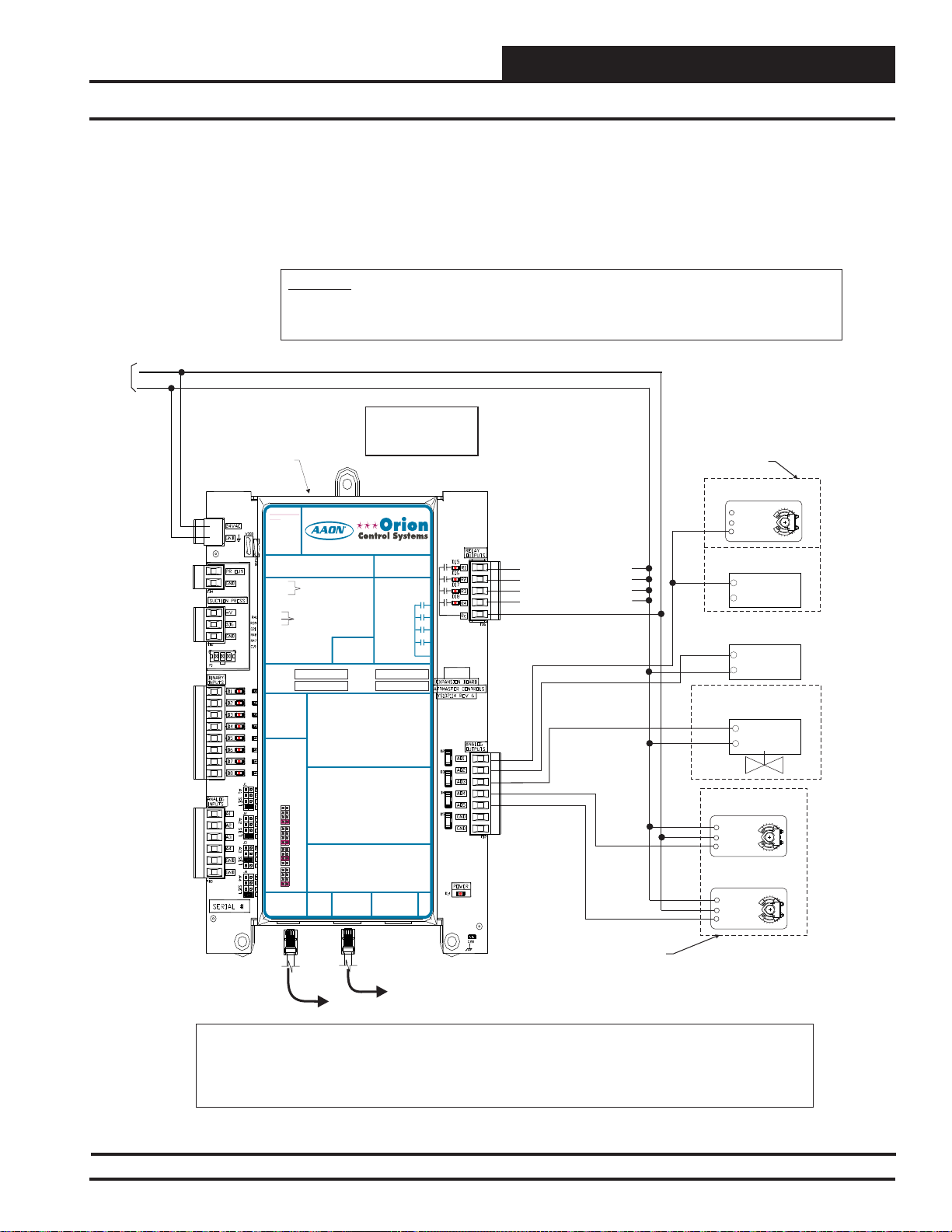
INSTALLATION AND WIRING
VCM-X Expansion Module Output Wiring for the RNE Controller
The expansion modules can be used individually or together to provide
the required inputs and outputs for your specifi c applications.
The VCM-X Expansion Module must be connected to 24 VAC as shown
in the wiring diagram below. Please see Table 1 on page 17 for correct
VA requirements to use when sizing the transformer(s) used for power ing the expansion module.
WARNING!!
Observe Polarity! All boards must be wired with GND-to-GND and 24VAC-to-24VAC. Failure to observe polarity will result in
damage to one or more of the boards. Expansion Modules must be wired in such a way that the expansion modules and the
controller are always powered together. Loss of power to the expansion module will cause the controller to become inoperative
until power is restored to the expansion module.
24 VAC
GND
10 VA Minimum
Power Required For
VCM-X Expansion
Module
VCM-X Expansion
Module
POLARITY
WARNING
OBSERVE
24 VAC POWER
24 VAC POWER ONLY
ONLY
WARNING!POLARITY MUST BE
WARNING!
OBSERVED OR THE BOARD
POLARITY
WILL BE DAMAGED
MUST BE
OBSERVED OR
THE BOARD
WILL BE
DAMAGED
PR OUT
GND
+V
SIG
GND
RELAY1 = RELAY3 =
RELAY2 = RELAY4 =
ITIS SUGGESTED
THATYOU WRITE THE
DESCRIPTION OF
THE RELAYOUTPUTS
YOUARE USING IN
THE BOXES
PROVIDEDABOVE
WITHA PERMANENT
MARKER (SHARPIE®)
JUMPER SETTINGS
www.aaon.com
VCM-X Expansion Module
Orion No.:OE333-23-EM
TO VCM-X INPUT
OE333-23-EM-AVCM-X EXPANSION MODULE
TERMINALS AI5 & GND
PR OUT
TO VCM-X INPUT
GND
TERMINALS AI5 & GND
SUCTION PRESSURE
TRANSDUCER CONNECTION
FOR HVAC UNITS WITHOUT
DIGITALCOMPRESSOR
SUCTION PRESSURE
+V
TRANSDUCER CONNECTION
SIG
FOR HVAC UNITS WITHOUT
GND
DIGITALCOMPRESSOR
RELAY1 = RELAY 3 =
BI1 = EMERGENCY SHUTDOWN - N.C. INPUT
BI2
RELAY2 = RELAY 4 =
BI3
BI4
ITIS SUGGESTED
BI5
BI1 = HOOD ON - N.O. INPUT
THATYOU WRITE THE
DESCRIPTION OF
THE RELAYOUTPUTS
YOUARE USING IN
THE BOXES
PROVIDEDABOVE
WITHA PERMANENT
ANALOG INPUT
MARKER (SHARPIE®)
MUST BE SETAS
JUMPER SETTINGS
ANALOG INPUT
= DIRTY FILTER - N.O. INPUT
BI2
BI6
= PROOF OF FLOW - N.O. INPUT
BI3
BI7
= REMOTE FORCED OCCUPIED - N.O. INPUT
BI4
BI8
= REMOTE FORCED HEATING - N.O. INPUT
BI5
= REMOTE FORCED COOLING - N.O. INPUT
BI6
NOTE:
BI7
= SMOKE DETECTOR - N.C. INPUT
ALL BINARY INPUTS MUSTBE 24 VAC ONLY.
BI8
= REMOTE DEHUMIDIFICATION - N.O. INPUT
SHOWN FOR
PROPER
ANALOG INPUT
NOTE:
AO1 = BUILDING PRESSURE CONTROL VFD OR
OPERATION
ALL BINARYINPUTS MUST BE 24 VAC ONLY.
MUST BE SETAS
AO2
SHOWN FOR
PROPER
JUMPER
AO1 = BUILDING PRESSURE CONTROL VFD OR
OPERATION
AO3
SETTINGS
AO2
THERM
AO4
ANALOG INPUT
4-20mA
AI1
JUMPER
0-10V
AO3
AO5
SETTINGS
0-5V
THERM
THERM
AO4
GND
4-20mA
4-20mA
AI1
AI2
0-10V
GND
0-10V
AO5
0-5V
0-5V
THERM
THERM
GND
AI1 = OUTDOOR AIR RH SENSOR (0-5 VDC)
4-20mA
4-20mA
AI2
AI3
GND
0-10V
AI2
0-10V
0-5V
0-5V
A3
I
THERM
AI4
THERM
AI1 = OUTDOOR AIR RH SENSOR (0-5 VDC)
4-20mA
4-20mA
GND
AI3
AI4
0-10V
AI2
= INDOOR AIR RH SENSOR (0-5 VDC)
0-10V
GND
0-5V
AI3
= CO2 (0-10 VDC)
0-5V
AI4
= BUILDING STATIC PRESSURE (0-5 VDC)
THERM
4-20mA
GND
AI4
0-10V
GND
I2C
0-5V
EXPANSION
Note:
All Relay Outputs Are Normally
Open And Rated For 24 VAC
Power Only. 1 Amp Maximum
Load.
I2C
EXPANSION
= DIRTY FILTER - N.O. INPUT
= PROOF OF FLOW - N.O. INPUT
= REMOTE FORCED OCCUPIED - N.O. INPUT
= REMOTE FORCED HEATING - N.O. INPUT
= REMOTE FORCED COOLING - N.O. INPUT
= HOOD ON - N.O. INPUT
= REMOTE DEHUMIDIFICATION - N.O. INPUT
DAMPER ACTUATOR (0-10 OR 2-10 VDC)
= MODULATING HEATING SIGNAL
(0-10 VDC OR 2-10 VDC)
= MODULATING COOLING/DIGITALSCROLL
DAMPER ACTUATOR (0-10 OR 2-10 VDC)
SIGNAL (0-10 VDC, 2-10 VDC OR 1.5-5 VDC)
= MODULATING HEATING SIGNAL
= RETURN AIR DAMPERACTUATOR
(0-10 VDC OR 2-10 VDC)
(0-10 VDC)
= MODULATING COOLING/DIGITALSCROLL
= RETURN AIR BYPASS DAMPERACTUATOR
SIGNAL (0-10 VDC, 2-10 VDC OR 1.5-5 VDC)
(0-10 VDC)
= RETURN AIR DAMPERACTUATOR
= GROUND FOR ANALOG OUTPUTS
(0-10 VDC)
= GROUND FOR ANALOG OUTPUTS
= RETURN AIR BYPASS DAMPERACTUATOR
(0-10 VDC)
= GROUND FOR ANALOG OUTPUTS
= GROUND FOR ANALOG OUTPUTS
= INDOOR AIR RH SENSOR (0-5 VDC)
= ECONOMIZER FEEDBACK
= BUILDING STATIC PRESSURE (0-5 VDC)
= GROUND FOR ANALOG INPUTS
= GROUND FOR ANALOG INPUTS
= GROUND FOR ANALOG INPUTS
= GROUND FOR ANALOG INPUTS
I2C
EXPANSION
WattMaster Label
EXPANSION
#LB102034-01
www.orioncontrols.com
AAON No.:
R69190
www.orioncontrols.com
RELAYCONTACT
RATING IS 1AMP
MAX @ 24 VAC
RELAYCONTACT
RELAY1
RATING IS 1AMP
MAX @ 24 VAC
RELAY2
RELAY1
RELAY3
RELAY2
RELAY4
RELAY3
RELAY
COMMON
RELAY4
RELAY
COMMON
WattMaster Label
#LB102034-01-A
Rev.: 1L
I2C
VCM
Also please note that when wiring the VCM-X Expansion Module, its
contacts must be wired as wet contacts (connected to 24 VAC).
Relay Output Contacts R1 Through R4 May
Be User-Configured For The Following:
1 - Heating Stages
2 - Cooling Stages
3 - Warm-up Mode Command (VAV Boxes)
4 - Reversing Valve (Heat Pumps)
5 - Reheat Control (Dehumidification)
6 - Exhaust Fan Interlock
7 - Preheater For Low Ambient Protection
8 - Alarm
9 - Override
10 - Occupied
11 - OA Damper
12 - Heat Wheel
13 - Emergency Heat
Note:
A Total Of 20 Relays Are Available By
Adding Relay Expansion Modules. All
Expansion Module Relay Outputs Are User
Configurable As Listed Above.
R1
Configurable Relay Output #1
R2
Configurable Relay Output #2
R3
Configurable Relay Output #3
R4
Configurable Relay Output #4
A1O
AO2
AO3
AO4
AO5
Either A Building Pressure
Damper Actuator Or a
Building Pressure Relief
Fan VFD Can Be Used,
-
Building Pressure Control
Damper Actuator
1 COM
2 +
3Y1
Building Pressure
Relief Fan VFD
+
COM
Modulating Heating
(0 to 10 VDC
Or 2 to 10 Input)
+
COM
Modulating Chilled Water Valve
(0 To 10 Or 2 To 10 VDC Input)
+
COM
Return Air
Damper Actuator
(0-10 VDC)
1 COM
2 +
3Y1
Return Air Bypass
Damper Actuator
(0-10 VDC)
1 COM
2 +
3Y1
Belimo Actuator Wiring
Shown. Consult Factory
Modular Cable
Connect To Next Expansion
Board (When Used)
Notes:
1.) The Modulating Chilled Water Valve Used Must Be Capable Of Accepting Either A 0-10 VDC or 2-10 VDC Input. The Modulating Cooling Output Voltage Is User
Configurable For These Voltages. The Modulating Heating Devices Used Must Be Capable of Accepting Either A 0-10 VDC or 2-10 VDC Input. The Modulating Heating
Output Voltage Is User- Configurable For These Voltages. These Voltage Outputs Must Also Be Configured When You Are Setting Up The RNE Controller(s) Operating
Parameters.
2.) Each Modulating Heating Or Cooling Device Used On The RNE Controller Must Have (1) Relay Output Configured For Each Device Used, In Order To Enable The
Modulating Heating And/Or Cooling Device's Sequence. This Relay Output Must Be Configured When Setting Up The RNE Controller Operating Parameters.
Modular Cable
Connect To RNE
Controller
For Other Manufacturer
Wiring Instructions
Figure 18: OE333-23-EM – VCM-X Expansion Module for RNE Output Wiring
RNE Modular Controller Field Technical Guide
27
Page 28

INSTALLATION AND WIRING
Binary Inputs Wiring
Zone
Zone
8 Binary Inputs Located On
VCM-X Expansion Module
If your HVAC unit only requires an Emergency Shutdown (Smoke
Detector/Firestat or other shutdown conditions), Dirty Filter, Proof of
Flow or Remote Forced Occupied Inputs or all of these 4 inputs and you
don’t need any of the other inputs or outputs provided on the OE33323-EM VCM-X Expansion Module, you can use the OE356-01-BI 4
Binary Input Expansion Module for these inputs. See Figure 20 on page
29 for OE356-01-BI wiring. If you require any other Binary Inputs or
require any other of the Analog Inputs or Outputs that are provided on
the VCM-X Expansion Module, you will need to use it instead for all
of your Binary Inputs.
24 VAC
GND
10 VA Minimum Power Required For
VCM-X Expansion Module
Emergency Shutdown - N.C. Contact
Dirty Filter - N.O. Contact
Proof Of Flow - N.O. Contact
Remote Forced Occupied - N.O. Contact
Remote Forced Heating - N.O. Contact
Remote Forced Cooling - N.O. Contact
Hood On - N.O. Contact
Remote Forced Dehumidification
N.O. Contact
WARNING!!
Observe Polarity! All boards must be wired with GND-to-GND and 24VAC-to24VAC. Failure to observe polarity will result in damage to one or more of the
boards. Expansion Modules must be wired in such a way that the expansion
modules and the controller are always powered together. Loss of power to the
expansion module will cause the controller to become inoperative until power is
restored to the expansion module.
WARNING
BI1
BI2
BI3
BI4
BI5
BI6
BI7
BI8
The transformer used for powering the VCM-X Expansion Module
must also be used to power the binary inputs. See Figure 19 below for
detailed wiring.
WARNING: Do not apply any voltage greater than 24 VAC
to the binary inputs. Higher voltages will damage the expansion
module and possibly other components on the system.
24 VAC POWER
24 VAC POWER ONLY
ONLY
WARNING!POLARITY MUST BE
WARNING!
OBSERVED OR THE BOARD
POLARITY
WILL BE DAMAGED
MUST BE
POLARITY
OBSERVE
OBSERVED OR
THE BOARD
WILL BE
DAMAGED
VCM-X Expansion Module
Orion No.:OE333-23-EM
OE333-23-EM-A VCM-X EXPANSION MODULE
PR OUT
GND
PR OUT
TO VCM-X INPUT
GND
TERMINALS AI5 & GND
SUCTION PRESSURE
+V
TRANSDUCER CONNECTION
SIG
FOR HVAC UNITS WITHOUT
GND
DIGITALCOMPRESSOR
SUCTION PRESSURE
+V
TRANSDUCER CONNECTION
SIG
FOR HVAC UNITS WITHOUT
GND
DIGITALCOMPRESSOR
RELAY1 = RELAY3 =
RELAY2 = RELAY4 =
RELAY1 = RELAY 3 =
ITIS SUGGESTED
THATYOU WRITE THE
DESCRIPTION OF
RELAY2 = RELAY 4 =
THE RELAYOUTPUTS
YOUARE USING IN
ITIS SUGGESTED
THE BOXES
THATYOU WRITE THE
PROVIDEDABOVE
DESCRIPTION OF
WITHA PERMANENT
THE RELAYOUTPUTS
MARKER (SHARPIE®)
YOUARE USING IN
THE BOXES
PROVIDEDABOVE
WITHA PERMANENT
ANALOG INPUT
MARKER (SHARPIE®)
JUMPER SETTINGS
MUST BE SETAS
SHOWN FOR
PROPER
ANALOG INPUT
OPERATION
JUMPER SETTINGS
MUST BE SETAS
SHOWN FOR
PROPER
ANALOG INPUT
OPERATION
JUMPER
SETTINGS
THERM
ANALOG INPUT
4-20mA
JUMPER
AI1
0-10V
SETTINGS
0-5V
THERM
THERM
4-20mA
4-20mA
AI1
AI2
0-10V
0-10V
0-5V
0-5V
THERM
THERM
4-20mA
AI2
4-20mA
0-10V
AI3
0-10V
0-5V
0-5V
THERM
THERM
4-20mA
AI3
4-20mA
0-10V
AI4
0-10V
0-5V
0-5V
THERM
4-20mA
AI4
0-10V
I2C
0-5V
EXPANSION
I2C
WattMaster Label
EXPANSION
#LB102034-01
www.aaon.com
TO VCM-X INPUT
TERMINALS AI5 & GND
BI1 = EMERGENCY SHUTDOWN - N.C. INPUT
BI2
= DIRTY FILTER - N.O. INPUT
= PROOF OF FLOW - N.O. INPUT
BI3
= REMOTE FORCED OCCUPIED - N.O. INPUT
BI4
BI1 = HOOD ON - N.O. INPUT
= REMOTE FORCED HEATING - N.O. INPUT
BI5
= DIRTY FILTER - N.O. INPUT
BI2
= REMOTE FORCED COOLING - N.O. INPUT
BI6
= PROOF OF FLOW - N.O. INPUT
BI3
= HOOD ON - N.O. INPUT
BI7
= REMOTE FORCED OCCUPIED - N.O. INPUT
BI4
= REMOTE DEHUMIDIFICATION - N.O. INPUT
BI8
= REMOTE FORCED HEATING - N.O. INPUT
BI5
= REMOTE FORCED COOLING - N.O. INPUT
BI6
NOTE:
= SMOKE DETECTOR - N.C. INPUT
BI7
ALL BINARY INPUTS MUSTBE 24 VAC ONLY.
= REMOTE DEHUMIDIFICATION - N.O. INPUT
BI8
NOTE:
AO1 = BUILDING PRESSURE CONTROL VFD OR
ALL BINARY INPUTS MUSTBE 24 VAC ONLY.
DAMPER ACTUATOR (0-10 OR 2-10 VDC)
= MODULATING HEATING SIGNAL
AO2
(0-10 VDC OR 2-10 VDC)
AO1 = BUILDING PRESSURE CONTROL VFD OR
= MODULATING COOLING/DIGITALSCROLL
AO3
DAMPER ACTUATOR (0-10 OR 2-10 VDC)
SIGNAL (0-10 VDC, 2-10 VDC OR 1.5-5 VDC)
AO2
= MODULATING HEATING SIGNAL
= RETURN AIR DAMPERACTUATOR
AO4
(0-10 VDC OR 2-10 VDC)
(0-10 VDC)
AO3
= MODULATING COOLING/DIGITALSCROLL
= RETURN AIR BYPASS DAMPERACTUATOR
AO5
SIGNAL (0-10 VDC, 2-10 VDC OR 1.5-5 VDC)
(0-10 VDC)
AO4
= RETURN AIR DAMPERACTUATOR
= GROUND FOR ANALOG OUTPUTS
GND
(0-10 VDC)
= GROUND FOR ANALOG OUTPUTS
GND
AO5
= RETURN AIR BYPASS DAMPERACTUATOR
(0-10 VDC)
GND
= GROUND FOR ANALOG OUTPUTS
AI1 = OUTDOOR AIR RH SENSOR (0-5 VDC)
GND
= GROUND FOR ANALOG OUTPUTS
AI2
= INDOOR AIR RH SENSOR (0-5 VDC)
I
A3
= ECONOMIZER FEEDBACK
AI4
= BUILDING STATIC PRESSURE (0-5 VDC)
AI1 = OUTDOOR AIR RH SENSOR (0-5 VDC)
GND
= GROUND FOR ANALOG INPUTS
AI2
= INDOOR AIR RH SENSOR (0-5 VDC)
GND
= GROUND FOR ANALOG INPUTS
AI3
= CO2 (0-10 VDC)
AI4
= BUILDING STATIC PRESSURE (0-5 VDC)
GND
= GROUND FOR ANALOG INPUTS
GND
= GROUND FOR ANALOG INPUTS
I2C
EXPANSION
www.orioncontrols.com
AAON No.:
www.orioncontrols.com
RELAYCONTACT
RATING IS 1AMP
MAX @ 24 VAC
RELAYCONTACT
RATING IS 1AMP
MAX @ 24 VAC
RELAY1
RELAY2
RELAY3
RELAY
RELAY4
COMMON
RELAY
COMMON
WattMaster Label
#LB102034-01-A
Rev.: 1L
I2C
EXPANSION
R69190
RELAY1
RELAY2
RELAY3
RELAY4
VCM
VCM-X Expansion Module
Figure 19: OE333-23-EM – VCM-X Expansion Module 8 Binary Inputs Wiring
28
RNE Modular Controller Field Technical Guide
Modular Cable
Connect To RNE
Controller
Modular Cable
Connect To Next Expansion
Board (When Used)
Page 29

INSTALLATION AND WIRING
Binary Inputs Wiring
4 Binary Inputs Located On 4 Binary
Input Expansion Module
If your HVAC unit only requires an Emergency Shutdown (Smoke
Detector/Firestat or other shutdown conditions), Dirty Filter, Proof of
Flow or Remote Forced Occupied Inputs or any combination of these 4
inputs and you don’t need any of the other inputs or outputs provided on
the OE333-23-EM VCM-X Expansion Module, you can use the OE35601-BI 4 Binary Input Expansion Module for these inputs.
The transformer used for powering the 4 Binary Input Expansion Module
must also be used to power the binary inputs. See Figure 20 below for
detailed wiring.
WARNING!!
Observe Polarity! All boards must be wired with GND-to-GND and 24VAC-to-24VAC. Failure to observe polarity
will result in damage to one or more of the boards. Expansion Modules must be wired in such a way that the
expansion modules and the controller are always powered together. Loss of power to the expansion module will
cause the controller to become inoperative until power is restored to the expansion module.
Modular Cable
Connect To Next Expansion
24 VAC
GND
5 VA Minimum Power
Required For
4 Binary Input
Expansion Module
Board (When Used)
WARNING: Do not apply any voltage greater than 24 VAC
to the binary inputs. Higher voltages will damage the expansion
module and possibly other components on the system.
Modular Cable
Connect To RNE
Controller
4 Binary Input
Expansion Module
Emergency Shutdown - N.C. Contact
Dirty Filter - N.O. Contact
Proof Of Flow - N.O. Contact
Remote Forced Occupied - N.O. Contact
Figure 20: OE356-01-BI – 4 Binary Input Expansion Module Wiring
GND
GND
COM
24 VAC
24VAC
BI1
BI1
VCM BIN EXP BOARD
YS102364 REV1
PWR
COM
BI2
BI4
BI3
BI2
BI4
BI3
RNE Modular Controller Field Technical Guide
29
Page 30

INSTALLATION AND WIRING
Outdoor Air Humidity Sensor Wiring
Zone
Zone
Outdoor Air Humidity Sensor
The OE265-13 Outdoor Air Humidity Sensor is connected to the system
by wiring it to the AI1 input on the VCM-X Expansion Module. It must
be wired as shown in Figure 21 below for proper controller operation.
24 VAC
GND
10 VA Minimum Power Required For
VCM-X Expansion Module
OA Humidity Sensor
Span
VAC or DC
GND
44556
3
2
1
Zero
0-5V or 0-10V
ON
Jumper
6
3
2
Must
1
Be Set To
0-5V As
ON
Shown
4
3
2
1
ON
Jumpers Must Be
Set as Shown
For Correct
O-5 VDC
Operation
1 & 3 Are Off
2 & 4 Are On
4-20 mA
4ON321
WARNING: It is very important to be certain that all wiring is
correct as shown in the wiring diagram below. Failure to observe
the correct polarity will result in damage to the OA Humidity Sensor or VCM-X Expansion Module.
WARNING!!
Observe Polarity! All boards must be wired with GND-to-GND and 24VAC-to24VAC. Failure to observe polarity will result in damage to one or more of the
boards. Expansion Modules must be wired in such a way that the expansion
modules and the controller are always powered together. Loss of power to
the expansion module will cause the controller to become inoperative until
power is restored to the expansion module.
24 VAC POWER
GND
24 VAC POWER ONLY
ONLY
WARNING!POLARITY MUST BE
WARNING!
OBSERVED OR THE BOARD
POLARITY
WILL BE DAMAGED
MUST BE
POLARITY
WARNING
OBSERVE
AI1
OBSERVED OR
THE BOARD
WILL BE
DAMAGED
VCM-X Expansion Module
Orion No.:OE333-23-EM
OE333-23-EM-AVCM-X EXPANSION MODULE
PR OUT
GND
PR OUT
GND
SUCTION PRESSURE
+V
TRANSDUCER CONNECTION
SIG
FOR HVAC UNITS WITHOUT
GND
DIGITALCOMPRESSOR
SUCTION PRESSURE
+V
TRANSDUCER CONNECTION
SIG
FOR HVAC UNITS WITHOUT
GND
DIGITALCOMPRESSOR
RELAY1 = RELAY 3 =
RELAY2 = RELAY 4 =
RELAY1 = RELAY 3 =
ITIS SUGGESTED
THATYOU WRITE THE
DESCRIPTION OF
RELAY2 = RELAY 4 =
THE RELAYOUTPUTS
YOUARE USING IN
THE BOXES
ITIS SUGGESTED
PROVIDEDABOVE
THATYOU WRITE THE
WITHA PERMANENT
DESCRIPTION OF
MARKER (SHARPIE®)
THE RELAYOUTPUTS
YOUARE USING IN
THE BOXES
PROVIDEDABOVE
WITHA PERMANENT
ANALOG INPUT
MARKER (SHARPIE®)
JUMPER SETTINGS
MUST BE SETAS
SHOWN FOR
PROPER
ANALOG INPUT
OPERATION
JUMPER SETTINGS
MUST BE SETAS
SHOWN FOR
ANALOG INPUT
PROPER
JUMPER
OPERATION
SETTINGS
THERM
ANALOG INPUT
4-20mA
AI1
JUMPER
0-10V
SETTINGS
0-5V
THERM
THERM
4-20mA
4-20mA
AI1
AI2
0-10V
0-10V
0-5V
0-5V
THERM
THERM
4-20mA
4-20mA
AI2
AI3
0-10V
0-10V
0-5V
0-5V
THERM
THERM
4-20mA
4-20mA
AI3
AI4
0-10V
0-10V
0-5V
0-5V
THERM
4-20mA
AI4
0-10V
I2C
0-5V
EXPANSION
I2C
WattMaster Label
EXPANSION
#LB102034-01
www.aaon.com
TO VCM-X INPUT
TERMINALS AI5 & GND
TO VCM-X INPUT
TERMINALS AI5 & GND
BI1 = EMERGENCY SHUTDOWN - N.C. INPUT
BI2
= DIRTY FILTER - N.O. INPUT
= PROOF OF FLOW - N.O. INPUT
BI3
= REMOTE FORCED OCCUPIED - N.O. INPUT
BI4
BI1 = HOOD ON - N.O. INPUT
= REMOTE FORCED HEATING - N.O. INPUT
BI5
BI2
= DIRTY FILTER - N.O. INPUT
= REMOTE FORCED COOLING - N.O. INPUT
BI6
BI3
= PROOF OF FLOW - N.O. INPUT
= HOOD ON - N.O. INPUT
BI7
BI4
= REMOTE FORCED OCCUPIED - N.O. INPUT
= REMOTE DEHUMIDIFICATION - N.O. INPUT
BI8
BI5
= REMOTE FORCED HEATING - N.O. INPUT
BI6
= REMOTE FORCED COOLING - N.O. INPUT
NOTE:
BI7
= SMOKE DETECTOR - N.C. INPUT
ALL BINARY INPUTS MUSTBE 24 VAC ONLY.
BI8
= REMOTE DEHUMIDIFICATION - N.O. INPUT
NOTE:
AO1 = BUILDING PRESSURE CONTROL VFD OR
ALL BINARYINPUTS MUST BE 24 VAC ONLY.
DAMPER ACTUATOR (0-10 OR 2-10 VDC)
= MODULATING HEATING SIGNAL
AO2
(0-10 VDC OR 2-10 VDC)
AO1 = BUILDING PRESSURE CONTROL VFD OR
= MODULATING COOLING/DIGITALSCROLL
AO3
DAMPER ACTUATOR (0-10 OR 2-10 VDC)
SIGNAL (0-10 VDC, 2-10 VDC OR 1.5-5 VDC)
= MODULATING HEATING SIGNAL
AO2
= RETURN AIR DAMPERACTUATOR
AO4
(0-10 VDC OR 2-10 VDC)
(0-10 VDC)
= MODULATING COOLING/DIGITALSCROLL
AO3
= RETURN AIR BYPASS DAMPERACTUATOR
AO5
SIGNAL (0-10 VDC, 2-10 VDC OR 1.5-5 VDC)
(0-10 VDC)
= RETURN AIR DAMPERACTUATOR
AO4
= GROUND FOR ANALOG OUTPUTS
GND
(0-10 VDC)
= GROUND FOR ANALOG OUTPUTS
GND
AO5
= RETURN AIR BYPASS DAMPERACTUATOR
(0-10 VDC)
GND
= GROUND FOR ANALOG OUTPUTS
AI1 = OUTDOOR AIR RH SENSOR (0-5 VDC)
GND
= GROUND FOR ANALOG OUTPUTS
AI2
= INDOOR AIR RH SENSOR (0-5 VDC)
A3
= ECONOMIZER FEEDBACK
I
AI4
= BUILDING STATIC PRESSURE (0-5 VDC)
AI1 = OUTDOOR AIR RH SENSOR (0-5 VDC)
GND
= GROUND FOR ANALOG INPUTS
AI2
= INDOOR AIR RH SENSOR (0-5 VDC)
GND
= GROUND FOR ANALOG INPUTS
AI3
= CO2 (0-10 VDC)
AI4
= BUILDING STATIC PRESSURE (0-5 VDC)
GND
= GROUND FOR ANALOG INPUTS
GND
= GROUND FOR ANALOG INPUTS
I2C
EXPANSION
www.orioncontrols.com
AAON No.:
www.orioncontrols.com
RELAYCONTACT
RATING IS 1AMP
MAX @ 24 VAC
RELAYCONTACT
RATING IS 1AMP
MAX @ 24 VAC
RELAY
COMMON
WattMasterLabel
#LB102034-01-A
EXPANSION
R69190
RELAY1
RELAY2
RELAY1
RELAY3
RELAY2
RELAY4
RELAY3
RELAY
RELAY4
COMMON
Rev.: 1L
I2C
VCM
Jumpers Must Be Set as
Shown For Normal
Operation Of Sensor
1, 2, 4, 5 & 6 Are Off
3 Is On
VCM-X Expansion
Module
Figure 21: OE265-13 – Outdoor Air Humidity Sensor Wiring
30
RNE Modular Controller Field Technical Guide
Modular Cable
Connect To RNE
Controller
Modular Cable
Connect To Next Expansion
Board (When Used)
Page 31

INSTALLATION AND WIRING
Indoor Wall-Mounted Humidity Sensor Wiring
Indoor Wall- Mounted Humidity Sensor
When used, the OE265-11 Indoor Wall-Mounted Humidity Sensor is
connected to the system by wiring it to the AI2 input on the VCM-X
Expansion Module. It must be wired as shown in Figure 22 below for
proper controller operation. Either the Space Humidity Sensor or the
RA Humidity Sensor can be wired into this input, but not both.
24 VAC
GND
10 VA Minimum Power Required For
VCM-X Expansion Module
Space Humidity Sensor
Zero
Span
4
3
2
1
Vo
Gnd
Io
Vin
ON
44556
3
2
1
ON
6
3
Jumpers Must Be Set as
Shown For Normal
Operation Of Sensor
1, 2, 4, 5 & 6 Are Off
3 Is On
2
1
ON
4
3
2
1
ON
Jumpers Must Be
Set as Shown
For Correct
O-5 VDC
Operation
1 & 3 Are Off
2 & 4 Are On
VCM-X Expansion Module
Jumper
Must
Be Set To
0-5V As
Shown
AI2
GND
WARNING: It is very important to be certain that all wiring is
correct as shown in the wiring diagram below. Failure to observe
the correct polarity will result in damage to the Space Humidity
Sensor or VCM-X Expansion Module.
WARNING!!
Observe Polarity! All boards must be wired with GND-to-GND and 24VACto-24VAC. Failure to observe polarity will result in damage to one or more
of the boards. Expansion Modules must be wired in such a way that the
expansion modules and the controller are always powered together. Loss
of power to the expansion module will cause the controller to become
inoperative until power is restored to the expansion module.
24 VAC POWER
ONLY
POLARITY
WARNING
OBSERVE
Modular Cable
Connect To RNE
Controller
24 VAC POWER ONLY
WARNING!
WARNING!POLARITY MUST BE
OBSERVED OR THE BOARD
POLARITY
WILL BE DAMAGED
MUST BE
OBSERVED OR
THE BOARD
WILL BE
DAMAGED
VCM-X Expansion Module
Orion No.:OE333-23-EM
PR OUT
OE333-23-EM-AVCM-X EXPANSION MODULE
GND
PR OUT
TO VCM-X INPUT
GND
TERMINALS AI5 & GND
SUCTION PRESSURE
+V
TRANSDUCER CONNECTION
SIG
FOR HVAC UNITS WITHOUT
GND
DIGITALCOMPRESSOR
SUCTION PRESSURE
+V
TRANSDUCER CONNECTION
SIG
FOR HVAC UNITS WITHOUT
GND
DIGITALCOMPRESSOR
RELAY1 = RELAY3 =
RELAY2 = RELAY4 =
ITIS SUGGESTED
RELAY1 = RELAY3 =
THATYOU WRITE THE
DESCRIPTION OF
RELAY2 = RELAY4 =
THE RELAYOUTPUTS
YOUARE USING IN
THE BOXES
ITIS SUGGESTED
PROVIDEDABOVE
THATYOU WRITE THE
WITHA PERMANENT
DESCRIPTION OF
MARKER (SHARPIE®)
THE RELAYOUTPUTS
YOUARE USING IN
THE BOXES
PROVIDEDABOVE
ANALOG INPUT
WITHA PERMANENT
JUMPER SETTINGS
MARKER (SHARPIE®)
MUST BE SETAS
SHOWN FOR
PROPER
ANALOG INPUT
OPERATION
JUMPER SETTINGS
MUST BE SETAS
SHOWN FOR
ANALOG INPUT
PROPER
JUMPER
OPERATION
SETTINGS
THERM
4-20mA
ANALOG INPUT
AI1
0-10V
JUMPER
0-5V
SETTINGS
THERM
THERM
4-20mA
4-20mA
AI2
AI1
0-10V
0-10V
0-5V
0-5V
THERM
THERM
4-20mA
4-20mA
AI3
AI2
0-10V
0-10V
0-5V
0-5V
THERM
THERM
4-20mA
4-20mA
AI4
AI3
0-10V
0-10V
0-5V
0-5V
THERM
4-20mA
AI4
0-10V
I2C
0-5V
EXPANSION
I2C
WattMaster Label
EXPANSION
#LB102034-01
www.aaon.com
TO VCM-X INPUT
TERMINALS AI5 & GND
BI1 = EMERGENCY SHUTDOWN - N.C. INPUT
= DIRTY FILTER - N.O. INPUT
BI2
= PROOF OF FLOW - N.O. INPUT
BI3
= REMOTE FORCED OCCUPIED - N.O. INPUT
BI4
= REMOTE FORCED HEATING - N.O. INPUT
BI5
BI1 = HOOD ON - N.O. INPUT
= REMOTE FORCED COOLING - N.O. INPUT
BI6
= DIRTY FILTER - N.O. INPUT
BI2
= HOOD ON - N.O. INPUT
BI7
= PROOF OF FLOW - N.O. INPUT
BI3
= REMOTE DEHUMIDIFICATION - N.O. INPUT
BI8
= REMOTE FORCED OCCUPIED - N.O. INPUT
BI4
= REMOTE FORCED HEATING - N.O. INPUT
BI5
NOTE:
= REMOTE FORCED COOLING - N.O. INPUT
BI6
ALL BINARY INPUTS MUSTBE 24 VAC ONLY.
BI7
= SMOKE DETECTOR - N.C. INPUT
BI8
= REMOTE DEHUMIDIFICATION - N.O. INPUT
AO1 = BUILDING PRESSURE CONTROL VFD OR
NOTE:
DAMPER ACTUATOR (0-10 OR 2-10 VDC)
ALL BINARYINPUTS MUST BE 24 VAC ONLY.
= MODULATING HEATING SIGNAL
AO2
(0-10 VDC OR 2-10 VDC)
= MODULATING COOLING/DIGITALSCROLL
AO3
AO1 = BUILDING PRESSURE CONTROL VFD OR
SIGNAL (0-10 VDC, 2-10 VDC OR 1.5-5 VDC)
DAMPER ACTUATOR (0-10 OR 2-10 VDC)
= RETURN AIR DAMPERACTUATOR
AO4
= MODULATING HEATING SIGNAL
AO2
(0-10 VDC OR 2-10 VDC)
(0-10 VDC)
= MODULATING COOLING/DIGITALSCROLL
AO3
= RETURN AIR BYPASS DAMPERACTUATOR
AO5
SIGNAL (0-10 VDC, 2-10 VDC OR 1.5-5 VDC)
(0-10 VDC)
AO4
= RETURN AIR DAMPERACTUATOR
= GROUND FOR ANALOG OUTPUTS
GND
(0-10 VDC)
= GROUND FOR ANALOG OUTPUTS
GND
AO5
= RETURN AIR BYPASS DAMPERACTUATOR
(0-10 VDC)
AI1 = OUTDOOR AIR RH SENSOR (0-5 VDC)
GND
= GROUND FOR ANALOG OUTPUTS
AI2
= INDOOR AIR RH SENSOR (0-5 VDC)
GND
= GROUND FOR ANALOG OUTPUTS
A3
= ECONOMIZER FEEDBACK
I
AI4
= BUILDING STATIC PRESSURE (0-5 VDC)
AI1 = OUTDOOR AIR RH SENSOR (0-5 VDC)
GND
= GROUND FOR ANALOG INPUTS
AI2
= INDOOR AIR RH SENSOR (0-5 VDC)
GND
= GROUND FOR ANALOG INPUTS
AI3
= CO2 (0-10 VDC)
AI4
= BUILDING STATIC PRESSURE (0-5 VDC)
GND
= GROUND FOR ANALOG INPUTS
GND
= GROUND FOR ANALOG INPUTS
I2C
EXPANSION
www.orioncontrols.com
AAON No.:
www.orioncontrols.com
RELAYCONTACT
RATING IS 1AMP
MAX @ 24 VAC
RELAYCONTACT
RATING IS 1AMP
MAX @ 24 VAC
RELAY1
RELAY2
RELAY3
RELAY4
RELAY
COMMON
WattMaster Label
#LB102034-01-A
I2C
EXPANSION
R69190
RELAY1
RELAY2
RELAY3
RELAY4
RELAY
COMMON
VCM
Rev.: 1L
Modular Cable
Connect To Next Expansion
Board (When Used)
Figure 22: OE265-11 – Indoor Wall-Mounted Humidity Sensor Wiring
RNE Modular Controller Field Technical Guide
31
Page 32

INSTALLATION AND WIRING
Return Air Mounted Humidity Sensor
Zone
Zone
Return Air Mounted Humidity Sensor
When used, the OE265-14 Return Air Mounted Humidity Sensor is
connected to the system by wiring it to the AI2 input on the VCM-X
Expansion Module. It must be wired as shown in Figure 23 below for
proper controller operation. Either the RA Humidity Sensor or the Space
Humidity Sensor can be wired into this input, but not both.
24 VAC
GND
10 VA Minimum Power Required For
VCM-X Expansion Module
RA Humidity Sensor
Span
VAC or DC
GND
44556
3
2
1
Zero
0-5V or 0-10V
ON
6
3
Jumper
2
1
Must
Be Set To
ON
0-5V As
Shown
4
3
2
1
ON
Jumpers Must Be Set
as Shown For
Correct
O-5 VDC Operation
1 & 3 Are Off
4-20 mA
4ON321
WARNING: It is very important to be certain that all wiring is
correct as shown in the wiring diagram below. Failure to observe
the correct polarity will result in damage to the RA Humidity Sensor or controller.
WARNING!!
Observe Polarity! All boards must be wired with GND-to-GND and
24VAC-to-24VAC. Failure to observe polarity will result in damage to
one or more of the boards. Expansion Modules must be wired in such
a way that the expansion modules and the controller are always
powered together. Loss of power to the expansion module will cause
the controller to become inoperative until power is restored to the
expansion module.
24 VAC POWER
AI2
GND
24 VAC POWER ONLY
ONLY
WARNING!POLARITY MUST BE
WARNING!
OBSERVED OR THE BOARD
POLARITY
WILL BE DAMAGED
MUST BE
OBSERVED OR
POLARITY
WARNING
OBSERVE
THE BOARD
WILL BE
DAMAGED
VCM-X Expansion Module
Orion No.:OE333-23-EM
PR OUT
TO VCM-X INPUT
OE333-23-EM-AVCM-X EXPANSION MODULE
GND
TERMINALS AI5 & GND
PR OUT
GND
SUCTION PRESSURE
+V
TRANSDUCER CONNECTION
SIG
FOR HVAC UNITS WITHOUT
GND
DIGITALCOMPRESSOR
SUCTION PRESSURE
+V
TRANSDUCER CONNECTION
SIG
FOR HVAC UNITS WITHOUT
GND
DIGITALCOMPRESSOR
RELAY1 = RELAY3 =
RELAY2 = RELAY4 =
RELAY1 = RELAY 3 =
ITIS SUGGESTED
THATYOU WRITE THE
DESCRIPTION OF
RELAY2 = RELAY 4 =
THE RELAYOUTPUTS
YOUARE USING IN
THE BOXES
ITIS SUGGESTED
PROVIDEDABOVE
THATYOU WRITE THE
WITHA PERMANENT
DESCRIPTION OF
MARKER (SHARPIE®)
THE RELAYOUTPUTS
YOUARE USING IN
THE BOXES
PROVIDEDABOVE
ANALOG INPUT
WITHA PERMANENT
MARKER (SHARPIE®)
JUMPER SETTINGS
MUST BE SETAS
SHOWN FOR
PROPER
ANALOG INPUT
OPERATION
JUMPER SETTINGS
MUST BE SETAS
SHOWN FOR
ANALOG INPUT
PROPER
JUMPER
OPERATION
SETTINGS
THERM
ANALOG INPUT
4-20mA
AI1
JUMPER
0-10V
SETTINGS
0-5V
THERM
THERM
4-20mA
4-20mA
AI2
AI1
0-10V
0-10V
0-5V
0-5V
THERM
THERM
4-20mA
4-20mA
AI2
AI3
0-10V
0-10V
0-5V
0-5V
THERM
THERM
4-20mA
4-20mA
AI3
AI4
0-10V
0-10V
0-5V
0-5V
THERM
4-20mA
AI4
0-10V
I2C
0-5V
EXPANSION
I2C
WattMaster Label
EXPANSION
#LB102034-01
www.aaon.com
TO VCM-X INPUT
TERMINALS AI5 & GND
BI1 = EMERGENCY SHUTDOWN - N.C. INPUT
BI2
= DIRTY FILTER - N.O. INPUT
BI3
= PROOF OF FLOW - N.O. INPUT
BI4
= REMOTE FORCED OCCUPIED - N.O. INPUT
BI5
= REMOTE FORCED HEATING - N.O. INPUT
BI1 = HOOD ON - N.O. INPUT
BI6
= REMOTE FORCED COOLING - N.O. INPUT
= DIRTY FILTER - N.O. INPUT
BI2
BI7
= HOOD ON - N.O. INPUT
= PROOF OF FLOW - N.O. INPUT
BI3
BI8
= REMOTE DEHUMIDIFICATION - N.O. INPUT
= REMOTE FORCED OCCUPIED - N.O. INPUT
BI4
= REMOTE FORCED HEATING - N.O. INPUT
BI5
BI6
= REMOTE FORCED COOLING - N.O. INPUT
NOTE:
BI7
= SMOKE DETECTOR - N.C. INPUT
ALL BINARYINPUTS MUST BE 24 VAC ONLY.
BI8
= REMOTE DEHUMIDIFICATION - N.O. INPUT
AO1 = BUILDING PRESSURE CONTROL VFD OR
NOTE:
ALL BINARYINPUTS MUST BE 24 VAC ONLY.
DAMPER ACTUATOR (0-10 OR 2-10 VDC)
AO2
= MODULATING HEATING SIGNAL
(0-10 VDC OR 2-10 VDC)
AO1 = BUILDING PRESSURE CONTROL VFD OR
AO3
= MODULATING COOLING/DIGITALSCROLL
DAMPER ACTUATOR (0-10 OR 2-10 VDC)
SIGNAL (0-10 VDC, 2-10 VDC OR 1.5-5 VDC)
= MODULATING HEATING SIGNAL
AO2
AO4
= RETURN AIR DAMPERACTUATOR
(0-10 VDC OR 2-10 VDC)
(0-10 VDC)
= MODULATING COOLING/DIGITALSCROLL
AO3
AO5
= RETURN AIR BYPASS DAMPERACTUATOR
SIGNAL (0-10 VDC, 2-10 VDC OR 1.5-5 VDC)
(0-10 VDC)
= RETURN AIR DAMPERACTUATOR
AO4
GND
= GROUND FOR ANALOG OUTPUTS
(0-10 VDC)
GND
= GROUND FOR ANALOG OUTPUTS
AO5
= RETURN AIR BYPASS DAMPERACTUATOR
(0-10 VDC)
GND
= GROUND FOR ANALOG OUTPUTS
AI1 = OUTDOOR AIR RH SENSOR (0-5 VDC)
GND
= GROUND FOR ANALOG OUTPUTS
AI2
= INDOOR AIR RH SENSOR (0-5 VDC)
I
A3
= ECONOMIZER FEEDBACK
AI4
= BUILDING STATIC PRESSURE (0-5 VDC)
AI1 = OUTDOOR AIR RH SENSOR (0-5 VDC)
GND
= GROUND FOR ANALOG INPUTS
AI2
= INDOOR AIR RH SENSOR (0-5 VDC)
GND
= GROUND FOR ANALOG INPUTS
AI3
= CO2 (0-10 VDC)
AI4
= BUILDING STATIC PRESSURE (0-5 VDC)
GND
= GROUND FOR ANALOG INPUTS
GND
= GROUND FOR ANALOG INPUTS
I2C
EXPANSION
www.orioncontrols.com
AAON No.:
www.orioncontrols.com
RELAYCONTACT
RATING IS 1AMP
MAX @ 24 VAC
RELAYCONTACT
RATING IS 1AMP
MAX @ 24 VAC
RELAY1
RELAY2
RELAY3
RELAY4
RELAY
COMMON
WattMaster Label
#LB102034-01-A
Rev.: 1L
EXPANSION
R69190
RELAY1
RELAY2
RELAY3
RELAY4
RELAY
COMMON
I2C
VCM
Jumpers Must Be Set
as Shown For Normal
Operation Of Sensor
1, 2, 4, 5 & 6 Are Off
3 Is On
VCM-X Expansion
Module
Figure 23: OE265-14 – Indoor Return Air-Mounted Humidity Sensor Wiring
32
RNE Modular Controller Field Technical Guide
Modular Cable
Connect To Next Expansion
Board (When Used)
Modular Cable
Connect To RNE
Controller
Page 33

INSTALLATION AND WIRING
Y1 3
+ 2
COM - 1
Economizer Feedback 5
Title 24 Economizer Actuator Feedback & Building Pressure Sensor
Title 24 Economizer Actuator
Feedback
If the controller has been confi gured for Title 24 Economizer operation,
the Economizer Actuator Feedback signal is wired to the AI3 input on
the VCM-X Expansion Module. It must be wired as shown in Figure
24 below for proper controller operation.
Warning: It is very important to be certain that all wiring is correct as shown in the wiring diagram below. Failure to observe the
correct polarity will result in damage to the HVAC Unit Controller
and the VCM-X Expansion Module.
Economizer Damper Actuator
(Belimo Actuator Shown)
See Economizer
Actuator Wiring
AO1
Controller
Title 24 Economizer
Actuator Feedback
Signal 0-10VDC
(By Others)
Belimo Actuator Wiring
Shown. Consult Factory
For Other Manufacturer
Wiring Instructions
NOTE: For Economizer
Actuator Wiring, See
Wiring For The
AO1
RNE Controller.
Building Pressure Sensor
The OE258-01 Building Pressure Sensor must be wired as shown in the
illustration below for proper operation. There are 3 terminal connections
on the Building Pressure Sensor. Connect the power side of the 24 VAC
power source to the terminal labeled “+ EXC.” Connect the GND side
of the 24 VAC power source to the terminal labeled “- COM.” Connect
the remaining terminal labeled “OUT” to AI4 on the VCM-X Expansion
Module terminal block. See Figure 25 below for detailed wiring. The
AI4 Jumper on the expansion module must be set for 0-5VDC operation
for the Building Pressure Sensor to operate correctly.
To GND
For RNE
VCM-X Expansion
Module
AI3
GND
Figure 24: Title 24 Economizer Actuator Feedback Wiring
Building Pressure Sensor
Tubing To Building
Pressure Sensing Location
Tubing To Atmospheric
Pressure Sensing Location
HIGH
LOW
Jumper Must
Be Set To
0-10V As Shown
24
To
VAC
GND
VCM-X Expansion
+
+
EXC
+
+
OUT
COM
-
-
Jumper Must
Be Set To
0-5V As Shown
Module
AI4
GND
Figure 25: OE258-01 — Building Pressure Sensor Wiring
RNE Modular Controller Field Technical Guide
33
Page 34

Zone
3Y1
2
1 - COM
+
INSTALLATION AND WIRING
Building Pressure Control Output Wiring
Zone
Building Pressure Control Output
The Building Pressure Control Output is a 0-10 VDC or 2-10 VDC signal
sent from the VCM-X Expansion Module. When using the output for
Direct Building Pressure Control (output signal rises on a rise in building pressure), the output signal can be connected to either a Variable
Frequency Drive controlling an exhaust fan or to a damper actuator
controlling an exhaust damper. When used in this manner, the output
signal must be confi gured for Direct Acting operation.
When using this output for Reverse Building Pressure Control (output
signal rises on a fall in building pressure), a damper actuator controlling
an OA Damper would be used. When using the OA damper for Reverse
Building Pressure Control, the output signal must be confi gured for
Reverse Acting operation. A Building Pressure Sensor connected to
WARNING!!
Observe Polarity! All boards must be wired with GND-to-GND and 24VAC-to-24VAC.
Failure to observe polarity will result in damage to one or more of the boards. Expansion
Modules must be wired in such a way that the expansion modules and the controller are
always powered together. Loss of power to the expansion module will cause the controller
to become inoperative until power is restored to the expansion module.
24 VAC POWER
L
POLARITY
WARNING
OBSERVE
VCM-X
Expansion
Module
Y
N
O
ER
W
C PO
24 VA
ONLY
PO
!
G
IN
RN
WA
WARNING!
O
ED
V
BSER
O
POLARITY
AG
BE DAM
ILL
W
MUST BE
OBSERVED OR
THE BOARD
WILLBE
DAMAGED
VCM-X Expansion Module
Orion No.:OE333-23-EM
PR OUT
OE333-23-EM-AVCM-X EXPANSION MODULE
GND
T
U
O
PR
D
N
G
SUCTION PRESSURE
+V
TRANSDUCER CONNECTION
SIG
FOR HVAC UNITS WITHOUT
GND
DIGITALCOMPRESSOR
S
+V
TR
SIG
FO
D
N
G
D
RELAY1 = RELAY3 =
RELAY2 = RELAY4 =
ITIS SUGGESTED
Y1 =
LA
E
R
THATYOU WRITE THE
DESCRIPTION OF
Y2 =
ELA
R
THE RELAYOUTPUTS
YOUARE USING IN
THE BOXES
ITIS SUGGESTED
PROVIDEDABOVE
THATYOU WRITE THE
WITHA PERMANENT
DESCRIPTION OF
MARKER (SHARPIE®)
THE RELAYOUTPUTS
YOUARE USING IN
THE BOXES
PROVIDEDABOVE
ANALOG INPUT
WITHA PERMANENT
JUMPER SETTINGS
MARKER (SHARPIE®)
MUSTBE SET AS
SHOWN FOR
PROPER
PUT
IN
G
LO
A
AN
OPERATION
PER SETTIN
JUM
SET
BE
UST
M
N FOR
SHOW
ANALOG INPUT
PROPER
JUMPER
TIO
A
PER
O
SETTINGS
THERM
4-20mA
INPU
G
ALO
AN
AI1
0-10V
PER
JUM
0-5V
S
SETTING
THERM
THERM
4-20mA
AI2
4-20mA
AI1
0-10V
0-10V
0-5V
0-5V
THERM
THERM
4-20mA
4-20m
AI3
AI2
0-10V
0-10V
0-5V
0-5V
THERM
THERM
4-20mA
4-20mA
AI4
AI3
0-10V
0-10V
0-5V
0-5V
THERM
4-20mA
AI4
I2C
0-10V
0-5V
EXPANSION
I2C
ST BE
U
M
RITY
LA
E BOAR
TH
R
ED
TO VCM-X INPUT
TERMINALSAI5 & GND
VC
TO
R
TE
TIO
C
U
S
AN
H
R
AL C
IT
IG
S
G
AS
N
T
A
N
SIO
AN
P
EX
D
www.aaon.com
T
PU
-X IN
M
D
N
G
I5 &
A
ALS
IN
M
E
R
U
SS
E
R
P
N
N
TIO
C
E
N
N
O
C
ER
C
U
D
T
U
O
ITH
ITS W
N
U
AC
V
R
O
SS
E
R
P
M
O
Y3 =
LA
E
R
BI1 = EMERGENCY SHUTDOWN - N.C. INPUT
= DIRTY FILTER - N.O. INPUT
BI2
BI3
BI4
BI5
B
BI6
BI2
BI7
BI3
BI8
B
BI5
NOTE:
B
ALL BINARYINPUTS MUST BE 24 VAC ONLY.
B
BI8
AO1 = BUILDING PRESSURE CONTROL VFD OR
N
ALL B
AO2
AO3
A
AO4
A
AO5
A
GND
A
GND
A
AI1 = OUTDOOR AIR RH SENSOR (0-5 VDC)
G
AI2
G
A3
AI4
A
GND
A
GND
A
A
G
G
Y4 =
ELA
R
= PROOF OF FLOW - N.O. INPUT
= REMOTE FORCED OCCUPIED - N.O. INPUT
= REMOTE FORCED HEATING - N.O. INPUT
. IN
.O
- N
N
O
D
O
O
= H
I1
= REMOTE FORCED COOLING - N.O. INPUT
- N.O
R
TY FILTE
IR
= D
= HOOD ON - N.O. INPUT
W
F FLO
F O
O
O
= PR
= REMOTE DEHUMIDIFICATION - N.O. INPUT
ED
C
R
FO
TE
O
EM
= R
I4
D
E
C
R
TE FO
O
EM
= R
D
E
C
R
FO
TE
O
EM
= R
I6
T
O
C
TE
E
D
KE
O
= SM
I7
ID
M
U
EH
TE D
O
EM
= R
:
TE
O
DAMPERACTUATOR (0-10 OR 2-10 VDC)
US
M
TS
PU
YIN
R
A
IN
= MODULATING HEATING SIGNAL
(0-10 VDC OR 2-10 VDC)
= MODULATING COOLING/DIGITALSCROLL
SU
S
E
R
P
G
IN
ILD
=BU
1
O
SIGNAL (0-10 VDC, 2-10 VDC OR 1.5-5 VDC)
TO
A
TU
AC
ER
P
AM
D
= RETURNAIR DAMPER ACTUATOR
E
H
G
TIN
LA
U
D
O
= M
2
O
(0-10 VDC)
2-10 V
R
O
C
(0-10 VD
= RETURNAIR BYPASS DAMPER ACTUATOR
O
C
G
TIN
LA
U
D
O
= M
3
O
(0-10 VDC)
C
D
(0-10 V
L
A
N
SIG
= GROUND FORANALOG OUTPUTS
M
A
D
IR
A
N
R
TU
E
= R
4
O
)
C
= GROUND FORANALOG OUTPUTS
(0-10 VD
YP
B
IR
A
N
R
TU
E
= R
5
O
)
C
D
(0-10 V
N
A
R
FO
D
N
U
O
R
= G
D
N
= INDOORAIR RH SENSOR (0-5 VDC)
AN
R
FO
D
N
U
O
R
= G
D
N
= ECONOMIZER FEEDBACK
I
= BUILDING STATIC PRESSURE (0-5 VDC)
H
R
IR
A
R
O
O
TD
U
= O
I1
= GROUND FORANALOG INPUTS
SE
H
R
IR
A
R
O
O
D
= IN
I2
= GROUND FORANALOG INPUTS
)
C
D
2 (0-10 V
O
= C
I3
ATIC
ST
G
IN
ILD
U
= B
I4
AN
R
FO
D
N
U
O
R
= G
D
N
I2C
N
A
R
FO
D
N
U
O
R
= G
D
N
EXPANSION
aster Label
WattM
#LB102034-01
www.orioncontrols.com
.orio
w
w
w
T
U
P
T
U
P
. IN
. INP
.O
- N
UP
C
C
O
TIN
EA
H
LIN
O
O
C
. IN
.C
- N
R
A
TIO
IFIC
E 24 VAC
B
T
O
E C
R
(0-10 O
R
SIG
G
TIN
A
)
C
D
/D
G
LIN
O
, 2-10 VD
C
A
PER
M
A
S D
AS
O
G
ALO
O
G
LO
A
O
S
SEN
(0-5 VD
R
O
S
N
U
S
ES
R
P
IN
G
LO
A
IN
G
LO
A
I2C
N
IO
S
N
A
P
EX
AAON No.:
R69190
ntrols.com
nco
RELAYCONTACT
RATING IS 1AMP
MAX @ 24 VAC
T
AC
T
N
O
YC
ELA
R
RELAY1
P
M
A
IS 1
G
TIN
A
R
C
A
24 V
@
AX
M
RELAY2
Y1
LA
E
R
RELAY3
Y2
ELA
R
RELAY4
Y3
ELA
R
RELAY
COMMON
Y4
ELA
R
Y
LA
E
R
N
O
M
M
O
C
T
U
.O
- N
IED
. IN
.O
- N
G
. IN
.O
- N
G
T
U
P
.O
- N
N
N
O
L
VFD
O
TR
N
2-10 VD
R
AL
N
LSC
A
IT
IG
1.5-5 VD
R
O
C
R
TO
A
TU
AC
ER
P
TS
TPU
U
TS
TPU
U
D
(0-5 V
R
C
E (0-5 V
R
TS
U
P
WattMaster Label
TS
U
P
#LB102034-01-A
Rev.: 1L
. IN
P
. IN
Y.
L
R
TU
)
C
)
D
VCM
T
U
P
T
U
T
PU
UT
P
R
O
)
C
LL
O
)
C
R
TO
A
)
C
Modular Cable
Connect To Next Expansion
Board (When Used)
AI4 on the VCM-X Expansion Module is used to sense and control the
signal to the Building Pressure Output. The OE258-01 Building Pressure
Sensor must be connected in order for the Building Pressure Output to
operate correctly.
See Figur e 26 below for detailed wiring of the Building Pressure Control
Output Signal.
CAUTION:
Variable Frequency Drive units can cause large
transient noise spikes that can cause interference to be propagated
on other electronic equipment. Use shielded wire wherever possible
and route all sensor and controller wiring away from the Variable
Frequency Drive and the HVAC unit electrical wiring.
24 VAC
GND
Wiring When Using Damper Actuator
For Building Pressure Control
Building Pressure Control
(By Others - Belimo Actuator Shown)
GND
24 VAC
Building Pressure Control
Exhaust Fan Variable Frequency Drive
0-10 VDC Input From AO1
AO1
Shield
GND
Caution: The VFD Unit Must Be Configured
For 0-10VDC Input. The Input Resistance At
The VFD Must Not Be Less Than 1000 Ohms
When Measured At The VFD Terminals With
All Input Wires Removed.
Wiring When Using Exhaust Fan VFD
For Building Pressure Control
Note:
Wire To The VFD Using 18 GA Minimum 2 Conductor Twisted
Pair With Shield Cable. Wire Shield To GND As Shown
10 VA Minimum Power
Required For
VCM-X Expansion Module
Damper Actuator
(By Others)
+
GND
+
_
GND
Shield
Belimo Actuator
Wiring Shown.
Consult Factory For
Other Manufacturer
Wiring Instructions
Both Types Of
Building
Pressure
Control
Devices Are
Shown
Only One Type
Of Building
Pressure
Control Device
May Be Used
On Each HVAC
Modular Cable
Connect To RNE
Controller
Figure 26: Building Pressure Control Output Wiring
34
RNE Modular Controller Field Technical Guide
Page 35

INSTALLATION AND WIRING
Modulating Heating Device Wiring
Modulating Heating Device
The Modulating Heating Device signal can be confi gured for either a
0-10 VDC or 2-10 VDC output signal when programming the controller .
The output signal can be confi gured for either Direct Acting or Reverse
Acting operation as required.
The Output signal is normally used to control a Modulating Hot Water
Valve or Modulating Steam Valve or is used for SCR Control of an
Electric Heating Coil.
WARNING!!
Observe Polarity! All boards must be wired with GND-to-GND and 24VAC-to-24VAC. Failure to observe
polarity will result in damage to one or more of the boards. Expansion Modules must be wired in such a way
that the expansion modules and the controller are always powered together. Loss of power to the expansion
module will cause the controller to become inoperative until power is restored to the expansion module.
24 VAC POWER
24 VAC POWER ONLY
ONLY
WARNING!POLARITY MUST BE
WARNING!
OBSERVED OR THE BOARD
POLARITY
WILLBE DAMAGED
MUST BE
OBSERVED OR
POLARITY
WARNING
OBSERVE
THE BOARD
WILLBE
DAMAGED
VCM-X Expansion Module
Orion No.:OE333-23-EM
PR OUT
OE333-23-EM-AVCM-X EXPANSION MODULE
GND
PR OUT
GND
SUCTION PRESSURE
+V
TRANSDUCER CONNECTION
SIG
FOR HVAC UNITS WITHOUT
GND
DIGITALCOMPRESSOR
SUCTION PRESSURE
+V
TRANSDUCER CONNECTION
SIG
FOR HVAC UNITS WITHOUT
GND
DIGITALCOMPRESSOR
RELAY1 = RELAY 3 =
RELAY2 = RELAY 4 =
RELAY1 = RELAY 3 =
ITIS SUGGESTED
THATYOU WRITE THE
DESCRIPTION OF
RELAY2 = RELAY 4 =
THE RELAYOUTPUTS
YOUARE USING IN
THE BOXES
ITIS SUGGESTED
PROVIDEDABOVE
THATYOU WRITE THE
WITHA PERMANENT
DESCRIPTION OF
MARKER (SHARPIE®)
THE RELAYOUTPUTS
YOUARE USING IN
THE BOXES
PROVIDEDABOVE
WITHA PERMANENT
ANALOG INPUT
MARKER (SHARPIE®)
JUMPER SETTINGS
MUSTBE SET AS
SHOWN FOR
PROPER
ANALOG INPUT
OPERATION
JUMPER SETTINGS
MUSTBE SET AS
SHOWN FOR
ANALOG INPUT
PROPER
JUMPER
OPERATION
SETTINGS
THERM
ANALOG INPUT
4-20mA
AI1
JUMPER
0-10V
SETTINGS
0-5V
THERM
THERM
4-20mA
4-20mA
AI1
AI2
0-10V
0-10V
0-5V
0-5V
THERM
THERM
4-20mA
4-20mA
AI2
AI3
0-10V
0-10V
0-5V
0-5V
THERM
THERM
4-20mA
4-20mA
AI3
0-10V
AI4
0-10V
0-5V
0-5V
THERM
4-20mA
AI4
0-10V
I2C
0-5V
EXPANSION
I2C
WattMaster Label
EXPANSION
#LB102034-01
www.aaon.com
TO VCM-X INPUT
TERMINALS AI5 & GND
TO VCM-X INPUT
TERMINALSAI5 & GND
BI1 = EMERGENCY SHUTDOWN - N.C. INPUT
BI2
= DIRTY FILTER - N.O. INPUT
BI3
= PROOF OF FLOW - N.O. INPUT
BI4
= REMOTE FORCED OCCUPIED - N.O. INPUT
BI1 = HOOD ON - N.O. INPUT
BI5
= REMOTE FORCED HEATING - N.O. INPUT
BI2
= DIRTY FILTER - N.O. INPUT
BI6
= REMOTE FORCED COOLING - N.O. INPUT
BI3
= PROOF OF FLOW - N.O. INPUT
BI7
= HOOD ON - N.O. INPUT
BI4
= REMOTE FORCED OCCUPIED - N.O. INPUT
BI8
= REMOTE DEHUMIDIFICATION - N.O. INPUT
BI5
= REMOTE FORCED HEATING - N.O. INPUT
BI6
= REMOTE FORCED COOLING - N.O. INPUT
NOTE:
BI7
= SMOKE DETECTOR - N.C. INPUT
ALL BINARYINPUTS MUST BE 24 VAC ONLY.
BI8
= REMOTE DEHUMIDIFICATION - N.O. INPUT
NOTE:
AO1 = BUILDING PRESSURE CONTROL VFD OR
ALL BINARYINPUTS MUST BE 24 VAC ONLY.
DAMPER ACTUATOR (0-10 OR 2-10 VDC)
= MODULATING HEATING SIGNAL
AO2
(0-10 VDC OR 2-10 VDC)
AO1 = BUILDING PRESSURE CONTROL VFD OR
= MODULATING COOLING/DIGITALSCROLL
AO3
DAMPERACTUATOR (0-10 OR 2-10 VDC)
SIGNAL (0-10 VDC, 2-10 VDC OR 1.5-5 VDC)
= MODULATING HEATING SIGNAL
AO2
= RETURN AIR DAMPERACTUATOR
AO4
(0-10 VDC OR 2-10 VDC)
(0-10 VDC)
= MODULATING COOLING/DIGITALSCROLL
AO3
AO5
= RETURN AIR BYPASS DAMPERACTUATOR
SIGNAL (0-10 VDC, 2-10 VDC OR 1.5-5 VDC)
(0-10 VDC)
= RETURNAIR DAMPER ACTUATOR
AO4
GND
= GROUND FOR ANALOG OUTPUTS
(0-10 VDC)
GND
= GROUND FOR ANALOG OUTPUTS
AO5
= RETURNAIR BYPASS DAMPER ACTUATOR
(0-10 VDC)
GND
= GROUND FORANALOG OUTPUTS
AI1 = OUTDOOR AIR RH SENSOR (0-5 VDC)
GND
= GROUND FORANALOG OUTPUTS
AI2
= INDOOR AIR RH SENSOR (0-5 VDC)
I
A3
= ECONOMIZER FEEDBACK
AI4
= BUILDING STATIC PRESSURE (0-5 VDC)
AI1 = OUTDOOR AIR RH SENSOR (0-5 VDC)
GND
= GROUND FOR ANALOG INPUTS
AI2
= INDOORAIR RH SENSOR (0-5 VDC)
GND
= GROUND FOR ANALOG INPUTS
AI3
= CO2 (0-10 VDC)
AI4
= BUILDING STATIC PRESSURE (0-5 VDC)
GND
= GROUND FORANALOG INPUTS
GND
= GROUND FORANALOG INPUTS
I2C
EXPANSION
www.orioncontrols.com
AAON No.:
www.orioncontrols.com
RELAYCONTACT
RATING IS 1AMP
MAX @ 24 VAC
RELAYCONTACT
RATING IS 1AMP
MAX @ 24 VAC
RELAY
COMMON
WattMaster Label
#LB102034-01-A
EXPANSION
R69190
RELAY1
RELAY2
RELAY1
RELAY3
RELAY2
RELAY4
RELAY3
RELAY
RELAY4
COMMON
Rev.: 1L
I2C
See Figure 27 below for detailed wiring of the Modulating Heating
Device.
WARNING: It is very important to be certain that all wiring is
correct as shown in the wiring diagram below. Failure to observe the
correct polarity could result in damage to the Modulating Heating
Device or the VCM-X Expansion Module.
24 VAC
GND
VCM
AO2
GND
10 VA Minimum Power Required
For VCM-X Expansion Module
Note:
1.) The Modulating Heating Device
Used On The RNE Controller Must
Have (1) Relay Output Configured
For It In Order To Enable The
Modulating Heating Device's
Sequence. This Relay Output Must
Be
Configured When Setting Up
The RNE Controller Operating
Parameters. The Modulating
Heating Output’s Voltage Can Also
Be Configured For Either 0 To 10
VDC Or 2 To 10 VDC In The
Configuration Menu.
Modulating Heating Device
(0 To 10 VDC Or 2 To 10 VDC Input)
+
_
GND
VCM-X
Expansion
Module
Modular Cable
Connect To Next Expansion
Board (When Used)
Modular Cable
Connect To RNE Controller
Figure 27: Modulating Heating Device Wiring
RNE Modular Controller Field Technical Guide
35
Page 36

INSTALLATION AND WIRING
Modulating Chilled Water Valve Wiring
Zone
Zone
Modulating Chilled Water Valve
The Modulating Chilled W ater Valve signal can be confi gured for either
a 0-10 VDC or 2-10 VDC output signal when programming the controller. The output signal can also be con fi gured for either Direct Acting or
Reverse Acting Water Valve operation as required by your application.
See Figure 28 below for wiring details.
For VFD Compressor wiring, see Figures 32-33 on pages 40-41 and
Figures 35-36 on pages 43-45.
WARNING!!
Observe Polarity! All boards must be wired with GND-to-GND and 24VAC-to-24VAC. Failure to
observe polarity will result in damage to one or more of the boards. Expansion Modules must
be wired in such a way that the expansion modules and the controller are always powered
together. Loss of power to the expansion module will cause the controller to become
inoperative until power is restored to the expansion module.
24 VAC POWER
24 VAC POWER ONLY
ONLY
WARNING!POLARITY MUST BE
WARNING!
OBSERVED OR THE BOARD
POLARITY
WILL BE DAMAGED
MUST BE
OBSERVED OR
POLARITY
WARNING
OBSERVE
THE BOARD
WILL BE
DAMAGED
VCM-X Expansion Module
Orion No.:OE333-23-EM
PR OUT
OE333-23-EM-AVCM-X EXPANSION MODULE
GND
PR OUT
GND
SUCTION PRESSURE
+V
TRANSDUCER CONNECTION
SIG
FOR HVAC UNITS WITHOUT
GND
DIGITALCOMPRESSOR
SUCTION PRESSURE
+V
TRANSDUCER CONNECTION
SIG
FOR HVAC UNITS WITHOUT
GND
DIGITALCOMPRESSOR
RELAY1 = RELAY 3 =
RELAY2 = RELAY 4 =
RELAY1 = RELAY 3 =
ITIS SUGGESTED
THATYOU WRITE THE
DESCRIPTION OF
RELAY2 = RELAY 4 =
THE RELAYOUTPUTS
YOUARE USING IN
THE BOXES
ITIS SUGGESTED
PROVIDEDABOVE
THATYOU WRITE THE
WITHA PERMANENT
DESCRIPTION OF
MARKER (SHARPIE®)
THE RELAYOUTPUTS
YOUARE USING IN
THE BOXES
PROVIDEDABOVE
WITHA PERMANENT
ANALOG INPUT
MARKER (SHARPIE®)
JUMPER SETTINGS
MUST BE SETAS
SHOWN FOR
PROPER
ANALOG INPUT
OPERATION
JUMPER SETTINGS
MUST BE SETAS
SHOWN FOR
ANALOG INPUT
PROPER
JUMPER
OPERATION
SETTINGS
THERM
ANALOG INPUT
4-20mA
AI1
JUMPER
0-10V
SETTINGS
0-5V
THERM
THERM
4-20mA
4-20mA
AI1
AI2
0-10V
0-10V
0-5V
0-5V
THERM
THERM
4-20mA
4-20mA
AI2
AI3
0-10V
0-10V
0-5V
0-5V
THERM
THERM
4-20mA
4-20mA
AI3
AI4
0-10V
0-10V
0-5V
0-5V
THERM
4-20mA
AI4
0-10V
I2C
0-5V
EXPANSION
I2C
WattMaster Label
EXPANSION
#LB102034-01
www.aaon.com
TO VCM-X INPUT
TERMINALS AI5 & GND
TO VCM-X INPUT
TERMINALS AI5 & GND
BI1 = EMERGENCY SHUTDOWN - N.C. INPUT
BI2
= DIRTY FILTER - N.O. INPUT
BI3
= PROOF OF FLOW - N.O. INPUT
BI4
= REMOTE FORCED OCCUPIED - N.O. INPUT
BI5
= REMOTE FORCED HEATING - N.O. INPUT
BI1 = HOOD ON - N.O. INPUT
= DIRTY FILTER - N.O. INPUT
BI2
BI6
= REMOTE FORCED COOLING - N.O. INPUT
= PROOF OF FLOW - N.O. INPUT
BI3
BI7
= HOOD ON - N.O. INPUT
BI4
= REMOTE FORCED OCCUPIED - N.O. INPUT
BI8
= REMOTE DEHUMIDIFICATION - N.O. INPUT
BI5
= REMOTE FORCED HEATING - N.O. INPUT
BI6
= REMOTE FORCED COOLING - N.O. INPUT
NOTE:
BI7
= SMOKE DETECTOR - N.C. INPUT
ALL BINARYINPUTS MUST BE 24 VAC ONLY.
BI8
= REMOTE DEHUMIDIFICATION - N.O. INPUT
NOTE:
AO1 = BUILDING PRESSURE CONTROL VFD OR
ALL BINARYINPUTS MUST BE 24 VAC ONLY.
DAMPER ACTUATOR (0-10 OR 2-10 VDC)
AO2
= MODULATING HEATING SIGNAL
(0-10 VDC OR 2-10 VDC)
AO1 = BUILDING PRESSURE CONTROL VFD OR
AO3
= MODULATING COOLING/DIGITALSCROLL
DAMPER ACTUATOR (0-10 OR 2-10 VDC)
SIGNAL (0-10 VDC, 2-10 VDC OR 1.5-5 VDC)
= MODULATING HEATING SIGNAL
AO2
AO4
= RETURN AIR DAMPERACTUATOR
(0-10 VDC OR 2-10 VDC)
(0-10 VDC)
= MODULATING COOLING/DIGITALSCROLL
AO3
AO5
= RETURN AIR BYPASS DAMPERACTUATOR
SIGNAL (0-10 VDC, 2-10 VDC OR 1.5-5 VDC)
(0-10 VDC)
AO4
= RETURN AIR DAMPERACTUATOR
GND
= GROUND FOR ANALOG OUTPUTS
(0-10 VDC)
GND
= GROUND FOR ANALOG OUTPUTS
AO5
= RETURN AIR BYPASS DAMPERACTUATOR
(0-10 VDC)
GND
= GROUND FOR ANALOG OUTPUTS
AI1 = OUTDOOR AIR RH SENSOR (0-5 VDC)
GND
= GROUND FOR ANALOG OUTPUTS
AI2
= INDOOR AIR RH SENSOR (0-5 VDC)
A3
= ECONOMIZER FEEDBACK
I
AI4
= BUILDING STATIC PRESSURE (0-5 VDC)
AI1 = OUTDOOR AIR RH SENSOR (0-5 VDC)
GND
= GROUND FOR ANALOG INPUTS
AI2
= INDOOR AIR RH SENSOR (0-5 VDC)
GND
= GROUND FOR ANALOG INPUTS
AI3
= CO2 (0-10 VDC)
AI4
= BUILDING STATIC PRESSURE (0-5 VDC)
GND
= GROUND FOR ANALOG INPUTS
GND
= GROUND FOR ANALOG INPUTS
I2C
EXPANSION
www.orioncontrols.com
AAON No.:
www.orioncontrols.com
RELAYCONTACT
RATING IS 1AMP
MAX @ 24 VAC
RELAYCONTACT
RATING IS 1AMP
MAX @ 24 VAC
RELAY1
RELAY2
RELAY3
RELAY4
RELAY
COMMON
WattMaster Label
#LB102034-01-A
Rev.: 1L
EXPANSION
R69190
RELAY1
RELAY2
RELAY3
RELAY4
RELAY
COMMON
WARNING: It is very important to be certain that all wiring is
correct as shown in the wiring diagram below. Failure to observe the
correct polarity could result in damage to the Modulating Chilled
Water Valve or the VCM-X Expansion Module.
24 VAC
GND
10 VA Minimum Power Required For
VCM-X Expansion Module
I2C
VCM
Notes:
1.) The Modulating Chilled Water Valve Used
Must Be Capable Of Accepting Either A0-10
VDC Or 2-10 VDC Input. The Modulating
Chilled Water Valve
Configurable For These Voltages. This
Voltage Output Must Be Configured When
You Are Setting Up The RNE Controller’(s)
Operating Parameters.
2.) The Modulating e Used
On The RNE Controller Must Have (1) Relay
Output Configured In Order To Enable The
Modulating 's Sequence.
This Relay Output Must Be Configured When
Setting Up The RNE Controller Operating
Parameters.
Modulating
AO3
GND
Output Voltage Is User-
Chilled Water Valv
Chilled Water Valve
Chilled Water Valve
0-10 VDC Or 2-10 VDC
(Configurable)
+
_
GND
VCM-X
Expansion
Module
Figure 28: Modulating Chilled Water Valve Wiring
36
RNE Modular Controller Field Technical Guide
Modular Cable
Connect To RNE Controller
Modular Cable
Connect To Next Expansion
Board (When Used)
Page 37

INSTALLATION AND WIRING
Return Air Bypass Wiring
Return Air Bypass
The RNE Controller can be confi gured for AAON® P AC or DPAC control schemes. Both AAON® PAC and DPAC control schemes provide
improved moisture removal capabilities while utilizing internal space
loads for reheat by redirecting the Return Air around the Evaporator Coil
instead of through the coil. See the AAON® PAC and DPAC applications section of this manual on page 5 for complete operation details.
The AAON® PAC and DP AC control schemes utilize a Return Air Bypass Damper Actuator and a Return Air Damper Actuator to modulate
the Return Air and Return Air Bypass Dampers to control the amount
of air that is redirected around the Evaporator Coil.
WARNING!!
Observe Polarity! All boards must be wired with GND-to-GND and 24VAC-to-24VAC. Failure
to observe polarity will result in damage to one or more of the boards. Expansion Modules
must be wired in such a way that the expansion modules and the controller are always
powered together. Loss of power to the expansion module will cause the controller to become
inoperative until power is restored to the expansion module.
24 VAC POWER
24 VAC POWER ONLY
ONLY
WARNING!POLARITY MUST BE
WARNING!
OBSERVED OR THE BOARD
POLARITY
WILLBE DAMAGED
MUST BE
OBSERVED OR
POLARITY
WARNING
OBSERVE
THE BOARD
WILL BE
DAMAGED
VCM-X Expansion Module
Orion No.:OE333-23-EM
PR OUT
OE333-23-EM-AVCM-X EXPANSION MODULE
GND
PR OUT
GND
SUCTION PRESSURE
+V
TRANSDUCER CONNECTION
SIG
FOR HVAC UNITS WITHOUT
GND
DIGITALCOMPRESSOR
SUCTION PRESSURE
+V
TRANSDUCER CONNECTION
SIG
FOR HVAC UNITS WITHOUT
GND
DIGITALCOMPRESSOR
RELAY1 = RELAY3 =
RELAY2 = RELAY4 =
RELAY1 = RELAY3 =
ITIS SUGGESTED
THATYOU WRITE THE
DESCRIPTION OF
RELAY2 = RELAY4 =
THE RELAYOUTPUTS
YOUARE USING IN
THE BOXES
ITIS SUGGESTED
PROVIDEDABOVE
THATYOU WRITE THE
WITHA PERMANENT
DESCRIPTION OF
MARKER (SHARPIE®)
THE RELAYOUTPUTS
YOUARE USING IN
THE BOXES
PROVIDEDABOVE
WITHA PERMANENT
ANALOG INPUT
MARKER (SHARPIE®)
JUMPER SETTINGS
MUST BE SETAS
SHOWN FOR
PROPER
ANALOG INPUT
OPERATION
JUMPER SETTINGS
MUSTBE SET AS
SHOWN FOR
ANALOG INPUT
PROPER
JUMPER
OPERATION
SETTINGS
THERM
ANALOG INPUT
4-20mA
AI1
JUMPER
0-10V
SETTINGS
0-5V
THERM
THERM
4-20mA
4-20mA
AI1
AI2
0-10V
0-10V
0-5V
0-5V
THERM
THERM
4-20mA
4-20mA
AI2
AI3
0-10V
0-10V
0-5V
0-5V
THERM
THERM
4-20mA
4-20mA
AI3
AI4
0-10V
0-10V
0-5V
0-5V
THERM
4-20mA
AI4
0-10V
I2C
0-5V
EXPANSION
I2C
WattMaster Label
EXPANSION
#LB102034-01
www.aaon.com
TO VCM-X INPUT
TERMINALS AI5 & GND
TO VCM-X INPUT
TERMINALS AI5 & GND
BI1 = EMERGENCY SHUTDOWN - N.C. INPUT
= DIRTY FILTER - N.O. INPUT
BI2
= PROOF OF FLOW - N.O. INPUT
BI3
= REMOTE FORCED OCCUPIED - N.O. INPUT
BI4
BI1 = HOOD ON - N.O. INPUT
= REMOTE FORCED HEATING - N.O. INPUT
BI5
= DIRTY FILTER - N.O. INPUT
BI2
= REMOTE FORCED COOLING - N.O. INPUT
BI6
= PROOF OF FLOW - N.O. INPUT
BI3
= HOOD ON - N.O. INPUT
BI7
= REMOTE FORCED OCCUPIED - N.O. INPUT
BI4
= REMOTE DEHUMIDIFICATION - N.O. INPUT
BI8
= REMOTE FORCED HEATING - N.O. INPUT
BI5
BI6
= REMOTE FORCED COOLING - N.O. INPUT
NOTE:
BI7
= SMOKE DETECTOR - N.C. INPUT
ALL BINARYINPUTS MUST BE 24 VAC ONLY.
BI8
= REMOTE DEHUMIDIFICATION - N.O. INPUT
NOTE:
AO1 = BUILDING PRESSURE CONTROL VFD OR
ALL BINARYINPUTS MUST BE 24 VAC ONLY.
DAMPER ACTUATOR (0-10 OR 2-10 VDC)
AO2
= MODULATING HEATING SIGNAL
(0-10 VDC OR 2-10 VDC)
AO1 = BUILDING PRESSURE CONTROL VFD OR
AO3
= MODULATING COOLING/DIGITALSCROLL
DAMPER ACTUATOR (0-10 OR 2-10 VDC)
SIGNAL (0-10 VDC, 2-10 VDC OR 1.5-5 VDC)
= MODULATING HEATING SIGNAL
AO2
AO4
= RETURN AIR DAMPERACTUATOR
(0-10 VDC OR 2-10 VDC)
(0-10 VDC)
= MODULATING COOLING/DIGITALSCROLL
AO3
AO5
= RETURN AIR BYPASS DAMPERACTUATOR
SIGNAL (0-10 VDC, 2-10 VDC OR 1.5-5 VDC)
(0-10 VDC)
= RETURN AIR DAMPERACTUATOR
AO4
GND
= GROUND FOR ANALOG OUTPUTS
(0-10 VDC)
= GROUND FOR ANALOG OUTPUTS
GND
= RETURN AIR BYPASS DAMPERACTUATOR
AO5
(0-10 VDC)
= GROUND FOR ANALOG OUTPUTS
GND
AI1 = OUTDOOR AIR RH SENSOR (0-5 VDC)
= GROUND FOR ANALOG OUTPUTS
GND
AI2
= INDOOR AIR RH SENSOR (0-5 VDC)
A3
= ECONOMIZER FEEDBACK
I
AI4
= BUILDING STATIC PRESSURE (0-5 VDC)
AI1 = OUTDOOR AIR RH SENSOR (0-5 VDC)
GND
= GROUND FOR ANALOG INPUTS
AI2
= INDOOR AIR RH SENSOR (0-5 VDC)
GND
= GROUND FOR ANALOG INPUTS
AI3
= CO2 (0-10 VDC)
AI4
= BUILDING STATIC PRESSURE (0-5 VDC)
GND
= GROUND FOR ANALOG INPUTS
GND
= GROUND FOR ANALOG INPUTS
I2C
EXPANSION
www.orioncontrols.com
AAON No.:
www.orioncontrols.com
RELAYCONTACT
RATING IS 1AMP
MAX @ 24 VAC
RELAYCONTACT
RATING IS 1AMP
MAX @ 24 VAC
WattMasterLabel
#LB102034-01-A
R69190
RELAY1
RELAY2
RELAY1
RELAY3
RELAY2
RELAY4
RELAY3
RELAY
RELAY4
COMMON
RELAY
COMMON
Rev.: 1L
I2C
EXPANSION
The AAON® DPAC control scheme provides improved moisture removal capabilities and tighter temperature control than the AAON® PAC
controls scheme by combining VFD Compressor control in addition to
Return Air Bypass control.
See Figure 29 below for detailed wiring of the Return Air Bypass and
Return Air Damper Actuators.
WARNING: It is very important to be certain that all wiring
is correct as shown in the wiring diagram below. Failure to observe
the correct polarity could result in damage to the Damper Actuator
or the VCM-X Expansion Module.
VCM
AO4
AO5
GND
24 VAC
GND
Shown. Consult Factory
For Other Manufacturer
10 VA Minimum Power
Required For
VCM-X Expansion Module
Belimo Actuator Wiring
Wiring Instructions.
Damper Actuator
1 COM
2 +
3Y1
1 COM
2 +
3Y1
Return Air Bypass
Damper Actuator
Return Air
(0-10 VDC)
(0-10 VDC)
VCM-X
Expansion
Module
Modular Cable
Connect To Next Expansion
Board (When Used)
Modular Cable
Connect To RNE Controller
Figure 29: Return Air Bypass Wiring
RNE Modular Controller Field Technical Guide
37
Page 38

Zone
EXP1
EXP1
EXP2
EXP2
INSTALLATION AND WIRING
Zone
12-Relay Expansion Module Wiring and Jumper Settings
12-Relay Expansion Module
When using the 12-Relay Expansion Module, you must correctly confi g-
ure a set of jumpers on the board depending on whether it will be used
Three different Expansion Modules are available for use with the
by itself or in addition to the VCM-X Expansion Module.
RNE Controller to provide additional inputs and outputs beyond those
found on the RNE Controller. They are the VCM-X Expansion Module
(OE333-23-EM), the 4 Binary Input Expansion Module ( OE356-01-BI)
which can be used in place of the VCM-X Expansion Module if your
system does not need any other inputs or outputs, and the 12-Relay
The jumpers are located on the edge of the 12-Relay Expansion Module
on the same side of the module as the power connection. See Figure
31 below for details regarding setting the switch correctly for your
application.
Expansion Module ( OE358-23-12R).
The 12-Relay Expansion Module provides for 12 Dry Contact Confi gu-
rable Relay Outputs. See Figure 30 below for complete wiring details.
The expansion modules can be used individually or together to provide
the required inputs and outputs for your specifi c applications.
WARNING!!
Observe Polarity! All boards must be wired with GND-to-GND and 24VAC-to-24VAC. Failure to observe polarity will result in damage to one or
more of the boards. Expansion Modules must be wired in such a way that the expansion modules and the controller are always powered
together. Loss of power to the expansion module will cause the controller to become inoperative until power is restored to the expansion module.
Modular Cable
Connect To RNE Controller
Note:
All Relay Outputs Are Normally Open
And Rated For 24 VAC Power Only.
1 Amp Maximum Load.
Relay Output Contacts R1 Through R12 May Be
User-Configured For The Following:
1 - Heating Stages
2 - Cooling Stages
3 - Warm-up Mode Command (VAV Boxes)
4 - Reversing Valve (Heat Pumps)
5 - Reheat Control (Dehumidification)
6 - Exhaust Fan Interlock
7 - Preheater For Low Ambient Protection
8 - Alarm
9 - Override
10 - Occupied
11 - OA Damper
12 - Heat Wheel
13 - Emergency Heat
A Total Of 20 Relays Are Available By Adding
Note:
Relay Expansion Modules. All Expansion Module
Relay Outputs Are User Configurable As Listed
Above.
R5
R6
R7
R8
R9
R10R2
R11R3
R12R4
-
Configurable Relay Output #5
Configurable Relay Output #6
Configurable Relay Output #7
Configurable Relay Output #8
Configurable Relay Output #9Configurable Relay Output #1
Configurable Relay Output #10Configurable Relay Output #2
Configurable Relay Output #11Configurable Relay Output #3
Configurable Relay Output #12Configurable Relay Output #4
Set Jumper As Shown Below
When Only The 12 Relay
Expansion Module Is Used
Set Jumper As Shown
Above When Both The 12
Relay & VCM-X Expansion
Module Are Used
R1
24 VAC
GND
Modular Cable
Connect To Next Expansion Board
(When Used)
15 VA Minimum Power
Required For
OE358-23-12R
12 Relay Expansion Module
12-Relay
Expansion Module
POWER
24VAC
GND
RLY1
RLY2
RLY3
RLY4
RLY COM
MADE IN USA
EXP1
EXP2
24 VAC POWER ONLY
WARNING!POLARITY MUST BE
OBSERVED OR THE BOARD
WILL BE DAMAGED
OE358-23-12R-A 12 RELAYEXPANSION MODULE
RLY1 = RLY7 =
RLY2 = RLY8 =
RLY3 = RLY9 =
RLY4 = RLY 10 =
RLY5 = RLY11 =
RLY6 = RLY 12 =
NOTE:
IT IS RECOMMENDED THATYOU WRITE THE
DESCRIPTION OF THE RELAYOUTPUTS YOU
ARE CONNECTING TO THE RELAYEXPANSION
MODULE IN THE BOXES PROVIDEDABOVE
USING APERMANENT MARKER (SHARPIE)
FOR FUTURE REFERENCE.
J1
EXP1
EXP2
SET JUMPERAS
SHOWN WHEN
ONLY
THE 12 RELAY
EXPANSION MODULE
IS USED
I2C
EXPANSION
WattMaster Label
www.orioncontrols.com
®
J1
EXP1
EXP2
EXPANSION
#LB102043
SET JUMPERAS
SHOWN WHEN BOTH
THE VCM EXPANSION
MODULE ANDTHE
RELAYEXPANSION
MODULE ARE USED
I2C
RELAY
EXPANSION BOARD
YS102228 REV 1
RLY5
RLY6
RLY7
RLY8
RLY COM
RLY9
RLY10
RLY11
RLY12
RLY COM
Figure 30: OE358-23-12R – 12-Relay Expansion Module Wiring and Jumper Settings
38
RNE Modular Controller Field Technical Guide
Page 39

INSTALLATION AND WIRING
Air Flow Monitoring Station Installation and Wiring
Air Flow Monitoring Station
Installation and Wiring
The OE365-15-EBA E-BUS Adapter Board is used to connect selected
Air Flow Monitoring Stations to the RNE Controller. Currently, there
are two Air Flow Monitoring Station options that are supported in our
standard software.
• EBTRON® - GTC-116 Series Air Flow Monitoring Station*
• GreenTrol™ Automation – GA-200-N Module used with
any GF Series Air Flow Monitoring Station
The wiring for the two Air Flow Monitoring Stations are the same and
are shown in Figure 31.
Connect To
RNE E-BUS Port
EMERGENCYSHUTDOWN
WARNING!POLARITY MUST BE OBSERVED
OR THE CONTROLLER WILLBE DAMAGED
I2C
EXPANSION
RNE Controller
24 VAC POWER ONLY
I2C DIGITAL
SENSOR
AI1
AI2
AI3
AI4
AI5
AI7
AI1 SET
AI2 SET AI3 SET
AI4 SET AI5 SET AI7 SET
ANALOG INPU
JUMPER
SETTINGS
THERM
4-20mA
AI1
0-10V
0-5V
THERM
4-20mA
AI2
0-10V
0-5V
THERM
4-20mA
AI3
0-10V
0-5V
THERM
4-20mA
AI4
0-10V
0-5V
THERM
4-20mA
AI5
0-10V
0-5V
THERM
4-20mA
AI7
0-10V
0-5V
ANALOG INPUTJUMPER SETTINGS
MUSTBE SET AS SHOWN FOR
PROPER OPERATION
STATIC
WattMaster Label
#LB102033-01
PRESSURE
*NOTE: When confi guring the GTC-116 Series, be sure to set
the Parity to “NO PARITY, 1 STOP BIT.”
NOTE: Up to 3 EBTRON® or GreenTrolTM Airfl ow Measure-
ment Digital Transmitters can be attached to each
Adapter Board.
NOTE: If using multiple E-BUS Sensors or Modules, the
E-BUS Hub (HZ-EBC-248 or MS000248) may be
required.
Airflow Measurement
Digital Transmitter Terminals
For Supply Air CFM
NET+
NETCOMM
NET+
NETCOMM
(Set Address Switch To 11)
Airflow Measurement
Digital Transmitter Terminals
For Return Air CFM
(Set Address Switch To 10)
OE365-15-EBA
E-BUS Adapter Board
HSSC Cable Connect To
RNE E-BUS Port
Figure 31: OE365-15-EBA - Airfl ow Monitoring Station To E-BUS Wiring
RNE Modular Controller Field Technical Guide
NET+
NETCOMM
Airflow Measurement
Digital Transmitter Terminals
For Outdoor Air CFM
(Set Address Switch To 9)
39
Page 40

Zone
INSTALLATION AND WIRING
Zone
RNE 55 - 105 Ton Unit Compressor and Condenser Wiring
Full Digital Module
RNE Units with DX Cooling will have either a Half VFD/Half Fixed
compressor confi guration or a Full VFD compressor confi guration. The
RNE 55 - 105 T on units have two compressors and will have either one
VFD and one Fixed Compressor or will have two VFD Compressors.
The operation of these compressors is described in the Sequence of
Operation section of this manual.
If this is not a Water Source Heat Pump unit, the outputs to the compressors will always be wired from the Full Digital Module ( OE37023-FD-A). Each compressor will need to have a relay confi gured and
wired from this module and the VFD output(s) will be wired from this
module. Each compressor will also have a Suction Pressure Transducer
wired into this module. See Figure 32 below for the wiring diagram.
OE370-23-FD-A
Full Digital Module
OE275-01 Suction
Pressure Transducer 1
+V
RD
WH
BK
RD
WH
BK
OE275-01 Suction
Pressure Transducer 2
This Dip
Switch Is Not
Used For This
Application
SIG 1
GND
SIG 2
GND
+V
+5V
SIG 1
GND
+5V
SIG 2
GND
+5V
SIG 3
GND
+5V
SIG 4
GND
BIN 1
BIN 2
COM
ADDRESS
PWR
The Full Digital Module connects to the RNE Controller or the Two
Condenser Head Pressure Module with an HSSC Cable. This allows
setpoints, status values, and alarms to be communicated between the
RNE Controller and the Full Digital Module. This module requires a
24 VAC power connection with an appropriate VA rating.
NOTE: The Compressor Relays on the Full Digital Module are
used rather than the relay outputs on the RNE Controller.
NOTE: For more information, see the Full Digital Module
Technical Guide on our website orioncontrols.com.
NOTE:
ALL RELAY OUTPUTS
NORMALLY OPEN AND
ARE
RATED FOR 24 VAC POWER
ONLY. 1 AMP MAXIMUM LOAD.
COMPRESSOR 1 ENABLE
COMPRESSOR 2 ENABLE
HVAC UNIT CONNECTIONS
+
COM
Compressor 1
+
COM
Compressor 2
WARNING!!
Observe Polarity! All
boards must be wired
with GND-to-GND and
24 VAC-to-24 VAC.
Failure to observe
polarity could result in
damage to the boards.
GND
RELAYS
ANALOG
R1
R2
AO1
AO2
OPTIONS
ALARM
STAT
COMM
R1
R2
R3
R4
Rc
AO1
AO2
GND
PWM1-
PWM1+
PWM2-
PWM2+
This Dip
Switch Is Not
Used For This
Application
24 VAC
HSSC Cable
Connect To RNE Controller
HSSC Cable
Figure 32: RNE 55 - 105 Ton Unit Two Compressor Full Digital Wiring
40
RNE Modular Controller Field Technical Guide
Line Voltage
24 VAC Transformer
3 VA Minimum
Connect To
Head Pressure Module
Page 41

INSTALLATION AND WIRING
RNE 55 - 105 Ton Unit Compressor and Condenser Wiring
WSHP-X2 Module
RNE Units with DX Cooling will have either a Half VFD/Half Fixed
compressor confi guration or a Full VFD compressor confi guration. The
RNE 55 - 105 T on units have two compressors and will have either one
VFD and one Fixed Compressor or will have two VFD Compressors.
The operation of these compressors is described in the Sequence of
Operation section of this manual.
On W ater Source Heat Pump (WSHP) units, the outputs to the compressors will always be wired from the WSHP-X2 Module. Each compressor
will need to have a relay confi gured and wired from this module, and the
VFD output(s) will be wired from this module. The Suction Pressure
Transducer for each compressor and the Proof of Flow switch for each
water circuit will also be wired into this module. See Figure 33 below
for the wiring diagram. The WSHP-X2 Module monitors conditions on
the unit and can disable compressors based on Low Suction Pressure,
Low Leaving Water Temperature, or a loss of Water Proof of Flow. It
also utilizes a Delay Timer to prevent the compressors from turning on
at the same time.
Heat Pump X2 Module
+V
SUCTION PRESSURE
TRANSDUCER 1
SUCTION PRESSURE
TRANSDUCER 2
WARNING!! Observe Polarity! All
boards must be wired with GND-toGND and 24 VAC-to-24 VAC.
Failure to observe polarity could
result in damage to the boards.
Connect To
RNE Controller
WATER POF 1
WATER POF 2
RD
SIG 1
WH
BK
GND
+V
RD
SIG 2
WH
BK
GND
BIN6
BIN7
COM
T1
T2
OE334-26-WSHP-X2 WSHP-X2 MODULE
+5V
PRES
GND
+5TO RED, PRES TO WHT & GND TO BLK
+5V
PRES
GND
+5 NOTUSED, PRES TO P6 & GND TO P5
BIN1
BIN2
BIN3
BIN4
BIN5
T1
T2
GND
CONNECT
GND
HSSC Cable
The WSHP-X2 Module connects to the RNE Controller or the Two
Condenser Head Pressure II Module with an HSSC Cable. This allows
setpoints, status values, and alarms to be communicated between the
RNE Controller and the WSHP-X2 Module. This module requires a 24
VAC power connection with an appropriate VA rating.
NOTE: The Compressor Relays on the WSHP-X2 Module are
used rather than the relay outputs on the RNE
Controller.
NOTE: For more information, see the WSHP-X2 Module Field
Technical Guide.
OE334-26-WSHP-X2
Water Source
ALARM
UP
M
BIN6
BIN7
COM
WattMaster Label
#S 000063
W
Rev.: 1B
- H2O POF A
- H2O POF B
- COMMON
CONNECT
E-BUS
HSSC
MENU
DOWN
AAON NO.: V48820
RELAYCONTACT RATING
IS 1AMP MAX @ 24 VAC
COMP.A1 ENABLE
COMP.A2 ENABLE
COMP. B1 ENABLE
COMP. B2 ENABLE
ALARM OUTPUT
RELAYCOMMON
DIGITAL/VFD COMPRESSORS
A1, A2, B1, B2
AOUT1 - COMPA1
AOUT2 - COMPA2
AOUT3 - COMP B1
AOUT4 - COMP B2
E
www.aaon.com
www.orioncontrols.com
NON-DIGITALCOMPRESSORS
SUCT. PR. SENSOR
PRES 1=A1, PRES 2=A2
PRES 3=B1, PRES 4=B2
DIGITALCOMRESSORS
NOT USED
PRES 1=A1, PRES 2=A2
PRES 3=B1, PRES 4=B2
- COMPA1 EN
- COMPA2 EN
- COMP B1 EN
- COMP B2 EN
- HEATENABLE
- LEAVING WATERTEMP
- LEAVING WATERTEMP
- GROUND
E-BUS
HSSC
ENTER
CONNECTTO
CNTLR C2
TERM.
GND
R1
R2
R3
R4
R5
RC
GND
+24 VAC
24 VAC
Y 102374 REV 0S
WATTMASTER CONTROLS
NOTE:
ARE
RATED FOR 24 VAC POWER
ONLY
MADE IN USA
R1
R3
R5
COMM
AOUT1
AOUT3
Line Voltage
24 VAC Transformer
3 VAMinimum
ALL RELAY OUTPUTS
NORMALLY OPEN AND
HVAC UNIT
CONNECTIONS
COMP. 1 ENABLE
COMP. 2 ENABLE
ALARM OUTPUT
Compressor 1
+
COM
Compressor 2
+
COM
WARNING!!
WARNING!!
Observe Polarity! All
Observe Polarity! All
boards must be wired
boards must be wired
with GND-to-GND and 24
with GND-to-GND and 24
VAC-to-24 VAC. Failure
VAC-to-24 VAC. Failure
to observe polarity could
to observe polarity could
result in damage to the
result in damage to the
boards.
boards.
LEAVING WATER
TEMPERATURE 1
LEAVING WATER
TEMPERATURE 2
Figure 33: RNE 55 - 105 Ton Unit Two Compressor WSHP-X2 Wiring
RNE Modular Controller Field Technical Guide
HSSC Cable
Connect ToTwo Condenser Head
Pressure II Module
41
Page 42

Zone
INSTALLATION AND WIRING
Zone
RNE 55 - 105 Ton Unit Compressor and Condenser Wiring
Two Condenser Head Pressure II
Module
For RNE 55 - 105 T on units, the T wo Condenser Head Pressure II Module
( OE370-23-HP2C2) will monitor two head pressure transducers and
control two condenser fans or water valves. A pulse width modulation
(PWM) signal or a 0-10 VDC output signal is used to control these
condenser devices. See Figure 34 below for the wiring diagram.
OE370-23-HP2C2
Two Condenser Head Pressure II Module
Head Pressure Transducers 1 - 2
Set ADDRESS Dip Switch 1 to ON for
Water Cooled or to OFF for Air Cooled.
Set ADDRESS Dip Switch 2 to OFF.
ADDRESS Dip Switch 3 should always
be set to OFF. Currently showing OFF.
Set ADDRESS Dip Switch 4 to OFF to
make reversing valve "ON to Heat /
OFF to Cool.” Set to ON to make
reversing valve “ON to Cool / OFF to
0 - 667 PSI
(One Per Refrigerant Circuit)
RD
WH
BK
RD
WH
BK
Currently showing OFF.
Currently showing OFF.
Heat.” Currently showing OFF.
Connect To
Full Digital Module
or WPM Module
SIG
GND
SIG
GND
+V
+V
+5V
SIG 1
GND
+5V
SIG 2
GND
+5V
SIG 3
GND
+5V
SIG 4
GND
BIN 1
BIN 2
BIN 3
COM
ADDRESS
PWR
HSSC Cable
www.aaon.com
MAX @ 24 VAC
RATING IS 1AMP
RELAYCONTACT
Two Condenser Head Pressure II Module
A1
+5V
HEAD
SIG 1
PRESSURE
GND
TRANSDUCER #1
A2
+5V
HEAD
SIG 2
PRESSURE
GND
TRANSDUCER #2
B1
+5V
HEAD
SIG 3
PRESSURE
GND
TRANSDUCER #3
B2
+5V
HEAD
SIG 4
PRESSURE
GND
TRANSDUCER #4
COND. AENABLE INPUT
BIN 1
REV. VLV. ENABLE INPUT
BIN 2
COND. B ENABLE INPUT
BIN 3
COM
COMMON
WattMaster Label
E-BUS
#LB102110-A
Connector
Rev.: 1A
2C2Orion No.:OE370-23-HP
LED NAME STAT
BLINKS QTY. OF SENSORS INSTALLED
LED NAME
NO PROBLEMS 0
NO SENSORS DETECTED 1
HIGH HEAD PRESSURE DETECTED 2
LOW HEADP RESSURE DETECTED 3
E-BUS
Connector
The T wo Condenser Head Pressure II Module connects to the Full Digital
Module, the Water Source Heat Pump Module, or the RNE Controller
with an HSSC cable. This allows setpoints, status values, and alarms to
be communicated between the RNE Controller and the T wo Condenser
Head Pressure II Module. This module requires a 24 VAC power connection with an appropriate VA rating.
NOTE: For more information, see the Two Condenser Head
Pressure Module II Technical Guide found on our
website orioncontrols.com.
HVAC UNIT CONNECTION
NOTE:
ALL RELAY OUTPUTS
NORMALLY OPEN AND
ARE
RATED FOR 24 VAC POWER
- 1 AMP MAXIMUM LOAD
ONLY
AAON No.:
V20660
GND
GND
PWM1PWM1+
PWM2PWM2+
ALARM
GND
R1
R2
R3
R4
RC
AO1
AO2
GND
+24 VAC
24 VAC
COND. AENABLE
REV. VLV. AENABLE
COND. B ENABLE
REV. VLV. B ENABLE
RELAYCOMMON
COND. ASIGNAL
COND. B SIGNAL
COND. FANA
COND. FANA
COND. FAN B
COND. FAN B
LED BLINK CODES
HSSC Cable
RELAYS
ANALOG
R1
R2
R3
R4
COMM
OPTIONS
ALARM
STAT
COMM
PWM1-
PWM1+
PWM2-
PWM2+
R1
R2
R3
R4
Rc
AO1
AO2
GND
Line Voltage
24 VAC Transformer
3 VA Minimum
YELLOW
BLUE +24 OUT
YELLOW
BLUE +24 OUT
E-BUS Expansion Module(s)
CONDENSER 1 ENABLE
REVERSING VALVE 1 ENABLE
CONDENSER 2 ENABLE
REVERSING VALVE 2 ENABLE
Condenser Fan 1
Condenser Fan 2
ECM Motor
OPTIONS Dip Switch Setting Not
Required When Connected To
RNE Controller.
WARNING!! Observe Polarity! All
boards must be wired with GND-toGND and 24 VAC-to-24 VAC.
Failure to observe polarity could
result in damage to the boards.
Connect To Other
WattMaster-Approved
Condenser
Signal 1
+
COM
Condenser
Signal 2
+
COM
ECM Motor
Duty Cycle
+24 Volts
Duty Cycle
+24 Volts
Figure 34: RNE 55 - 105 Ton Unit Two Compressor Two Condenser Head Pressure II Module Wiring
42
RNE Modular Controller Field Technical Guide
Page 43

INSTALLATION AND WIRING
RNE 120 - 140 Ton Unit Compressor and Condenser Wiring
Full Digital Module
RNE Units with DX Cooling will have either a Half VFD/Half Fixed
compressor confi guration or a Full VFD compressor confi guration. The
RNE 120 - 140 Ton units have four compressors and will have either
two VFD and two Fixed Compressors or will have four VFD Compressors. The operation of these compressors is described in the Sequence
of Operation section of this manual.
If this is not a Water Source Heat Pump unit, the outputs to the compressors will always be wired from the Full Digital Module ( OE37023-FD-A). Each compressor will need to have a relay confi gured and
wired from this module, and the VFD output(s) will be wired from this
module. Each compressor will also have a Suction Pressure Transducer
wired into this module. See Figure 35 below for the wiring diagram.
On units confi gured for Half VFD/Half Fixed operation, the two VFD
Compressors will both be driven from Analog Output (AO) #1, although
the individual compressor relays will be enabled separately as needed.
OE370-23-FD-A
Full Digital Module
OE275-01 Suction
Pressure Transducers 1 - 4
+V
RD
SIG 1
1
3
2
4
WH
BK
GND
RD
SIG 2
WH
BK
GND
RD
SIG 3
WH
BK
GND
RD
SIG 4
WH
BK
GND
This Dip
Switch Is Not
Used For This
Application
+V
+V
+V
+5V
SIG 1
GND
+5V
SIG 2
GND
+5V
SIG 3
GND
+5V
SIG 4
GND
BIN 1
BIN 2
COM
ADDRESS
PWR
On units confi gured for Full VFD operation, the 1st two VFD Compres-
sors will be driven from AO #1 and the 2nd two VFD Compressors
will be driven from AO #2, although all four compressor relays will be
enabled separately as needed.
The Full Digital Module connects to the RNE Controller or a Two
Condenser Head Pressure Module with an HSSC Cable. This allows
setpoints, status values, and alarms to be communicated between the
RNE Controller and the Full Digital Module. This module requires a
24 VAC power connection with an appropriate VA rating.
NOTE: The Compressor Relays on the Full Digital Module
are used rather than the relay outputs on the RNE
Controller.
NOTE: For more information, see the Full Digital Module
Technical Guide found on our website orioncontrols.
com.
NOTE:
ALL RELAY OUTPUTS
NORMALLY OPEN AND
ARE
RATED FOR 24 VAC POWER
ONLY. 1 AMP MAXIMUM LOAD.
COMPRESSOR 1 ENABLE
COMPRESSOR 3 ENABLE
COMPRESSOR 2 ENABLE
COMPRESSOR 4 ENABLE
HVAC UNIT CONNECTIONS
RELAYS
ANALOG
OPTIONS
O
ALARM
STAT
COMM
R1
R2
R3
R4
AO1
AO1
AO2
GND
This Dip
Switch Is Not
Used For This
Application
Compressor 1
+
COM
Compressor 2
+
COM
Compressor 3
+
COM
Compressor 4
+
COM
WARNING!!
Observe Polarity! All
boards must be wired
with GND-to-GND and
24 VAC-to-24 VAC.
Failure to observe
polarity could result in
damage to the boards.
GND
R1
R2
R3
R4
Rc
AO1
AO2
GND
PWM1-
PWM1+
PWM2-
PWM2+
24 VAC
HSSC Cable
Connect To
RNE Controller
24 VAC Transformer
3 VA Minimum
HSSC Cable
Head Pressure Module(s)
Figure 35: RNE 120 - 140 Ton Unit Four Compressor Full Digital Module Wiring
RNE Modular Controller Field Technical Guide
Line Voltage
Connect To
43
Page 44

Zone
AZ2-ALL-IOG-01F.indd
INSTALLATION AND WIRING
Zone
RNE 120 - 140 Ton Unit Compressor and Condenser Wiring
Water Source Heat Pump Module
RNE Units with DX Cooling will have either a Half VFD/Half Fixed
compressor confi guration or a Full VFD compressor confi guration. The
RNE 120 - 140 Ton units have four compressors and will have either
two VFD and two Fixed Compressors or will have four VFD Compressors. The operation of these compressors is described in the Sequence
of Operation section of this manual.
For W ater Source Heat Pump (WSHP) units, the outputs to the compressors will always be wired from the Water Source Heat Pump Modules.
For RNE 120 - 140 Ton units, two WSHP-X2 Modules will always be
+V
+V
RD
WH
WH
RD
SIG 1
SIG 1
WH
WH
BK
BK
GND
GND
+V
+V
RD
RD
SIG 2
SIG 2
BK
BK
GND
GND
BIN6
BIN6
BIN7
BIN7
COM
COM
T1
T1
T2
T2
GND
GND
HSSC Cable
HSSC Cable
OE334-26-WSHP-X2 WSHP-X2 MODULE
OE334-26-WSHP-X2 WSHP-X2 MODULE
PRES
PRES
GND
GND
PRES
PRES
GND
GND
BIN1
BIN1
BIN2
BIN2
BIN3
BIN3
BIN4
BIN4
BIN5
BIN5
T1
T1
T2
T2
GND
GND
SUCTION PRESSURE
SUCTION PRESSURE
TRANSDUCER 1
TRANSDUCER 1
SUCTION PRESSURE
SUCTION PRESSURE
TRANSDUCER 2
TRANSDUCER 2
WARNING!! Observe Polarity! All
WARNING!! Observe Polarity! All
boards must be wired with GND-to-
boards must be wired with GND-toGND and 24 VAC-to-24 VAC.
GND and 24 VAC-to-24 VAC.
Failure to observe polarity could
Failure to observe polarity could
result in damage to the boards.
result in damage to the boards.
Connect To
Connect To
RNE Controller
RNE Controller
WATER POF 1
WATER POF 1
WATER POF 2
WATER POF 2
used. Each compressor will need to have a relay confi gured and wired
from these modules, and the VFD outputs will be wired from these
modules. The Suction Pressure Transducer for each compressor and the
Proof of Flow switch for each water circuit will also be wired into these
modules. See Figure 36 below and on page 45 for the wiring diagram.
On units confi gured for Half VFD/Half Fixed operation, the two VFD
Compressors will be driven from AOUT #1 & 3 on the 1st WSHP-X2
Module, although the individual compressor relays will be enabled
separately as needed. On units confi gured for Full VFD operation,
the 1st two VFD Compressors will be driven from AOUT #1 & #2 on
the 1st WSHP-X2 Module and the 2nd two VFD Compressors will be
driven from AOUT #1 & #3 on the 2nd WSHP-X2 Module. All four
compressor relays will be enabled separately as needed.
OE334-26-WSHP-X2
OE334-26-WSHP-X2
Water Source
Water Source
Heat Pump X2 Module
Heat Pump X2 Module
ALARM
ALARM
UP
UP
M
M
MENU
BIN6
BIN6
BIN7
BIN7
COM
COM
#S 000063
W
#S 000063
W
Rev.: 1B
Rev.: 1B
- H2O POF A
- H2O POF A
- H2O POF B
- H2O POF B
- COMMON
- COMMON
CONNECT
CONNECT
E-BUS
E-BUS
MENU
DOWN
DOWN
AAON NO.: V48820
AAON NO.: V48820
RELAYCONTACT RATING
RELAYCONTACT RATING
IS 1AMP MAX @ 24 VAC
IS 1AMP MAX @ 24 VAC
COMP.A1 ENABLE
COMP.A1 ENABLE
COMP.A2 ENABLE
COMP.A2 ENABLE
COMP. B1 ENABLE
COMP. B1 ENABLE
COMP. B2 ENABLE
COMP. B2 ENABLE
ALARM OUTPUT
ALARM OUTPUT
RELAYCOMMON
RELAYCOMMON
DIGITAL/VFD COMPRESSORS
DIGITAL/VFD COMPRESSORS
A1, A2, B1, B2
A1, A2, B1, B2
AOUT1 - COMPA1
AOUT1 - COMPA1
AOUT2 - COMPA2
AOUT2 - COMPA2
AOUT3 - COMP B1
AOUT3 - COMP B1
AOUT4 - COMP B2
AOUT4 - COMP B2
HSSC
HSSC
E
E
GND
GND
www.aaon.com
www.aaon.com
www.orioncontrols.com
www.orioncontrols.com
NON-DIGITALCOMPRESSORS
NON-DIGITALCOMPRESSORS
SUCT. PR. SENSOR
SUCT. PR. SENSOR
+5V
+5V
PRES 1=A1, PRES 2=A2
PRES 1=A1, PRES 2=A2
PRES 3=B1, PRES 4=B2
PRES 3=B1, PRES 4=B2
+5 TO RED, PRESTO WHT & GND TO BLK
+5 TO RED, PRESTO WHT & GND TO BLK
DIGITALCOMRESSORS
DIGITALCOMRESSORS
+5V
+5V
NOT USED
NOT USED
PRES 1=A1, PRES 2=A2
PRES 1=A1, PRES 2=A2
PRES 3=B1, PRES 4=B2
PRES 3=B1, PRES 4=B2
+5 NOT USED, PRESTO P6 & GND TO P5
+5 NOT USED, PRESTO P6 & GND TO P5
- COMP A1 EN
- COMP A1 EN
- COMP A2 EN
- COMP A2 EN
- COMP B1 EN
- COMP B1 EN
- COMP B2 EN
- COMP B2 EN
- HEATENABLE
- HEATENABLE
- LEAVING WATERTEMP
- LEAVING WATERTEMP
- LEAVING WATERTEMP
- LEAVING WATERTEMP
- GROUND
- GROUND
E-BUS
E-BUS
WattMaster Label
WattMaster Label
HSSC
HSSC
CONNECT
CONNECT
ENTER
ENTER
CONNECTTO
CONNECTTO
CNTLR C2
CNTLR C2
TERM.
TERM.
GND
GND
R1
R1
R2
R2
R3
R3
R4
R4
R5
R5
RC
RC
+24 VAC
+24 VAC
24 VAC
24 VAC
Y 102374 REV 0S
Y 102374 REV 0S
WATTMASTER CONTROLS
WATTMASTER CONTROLS
MADE IN USA
MADE IN USA
NOTE:
NOTE:
ALL RELAY OUTPUTS
ALL RELAY OUTPUTS
NORMALLY OPEN AND
NORMALLY OPEN AND
ARE
ARE
RATED FOR 24 VAC POWER
RATED FOR 24 VAC POWER
ONLY
ONLY
HVAC UNIT
HVAC UNIT
CONNECTIONS
CONNECTIONS
R1
R3
R5
R5
COMM
COMM
AOUT1
AOUT1
COMP. 1 ENABLE
COMP. 2 ENABLE
ALARM OUTPUT
ALARM OUTPUT
AOUT3
Line Voltage
Line Voltage
24 VAC Transformer
24 VAC Transformer
3 VA Minimum
3 VA Minimum
Compressor 1
Compressor 1
+
+
COM
COM
Compressor 2
Compressor 2
+
+
COM
COM
WARNING!!
WARNING!!
WARNING!!
Observe Polarity! All
Observe Polarity! All
Observe Polarity! All
boards must be wired
boards must be wired
boards must be wired
with GND-to-GND and 24
with GND-to-GND and 24
with GND-to-GND and 24
VAC-to-24 VAC. Failure
VAC-to-24 VAC. Failure
VAC-to-24 VAC. Failure
to observe polarity could
to observe polarity could
to observe polarity could
result in damage to the
result in damage to the
result in damage to the
boards.
boards.
boards.
Figure 36: RNE 120 - 140 Ton Unit Four Compressor WSHP Module Wiring
44
LEAVING WATER
LEAVING WATER
TEMPERATURE 1
TEMPERATURE 1
LEAVING WATER
LEAVING WATER
TEMPERATURE 2
TEMPERATURE 2
HSSC Cable
Connect To 2nd
WSHP-X2 Module
RNE Modular Controller Field Technical Guide
Page 45

INSTALLATION AND WIRING
RNE 120 - 140 Ton Unit Compressor and Condenser Wiring
The WSHP-X2 Module monitors conditions on the unit and can disable compressors based on Low Suction Pressure, Low Leaving Water
Temperature, or a loss of Water Proof of Flow. It also utilizes a Delay
Timer to prevent the compressors from turning on at the same time.
The WSHP Modules connect together and then connect back to the RNE
Controller or the Two Condenser Head Pressure Modules with HSSC
cables. This allows setpoints, status values, and alarms to be communicated between the RNE Controller and the WSHP Module. This module
requires a 24 VAC power connection with an appropriate VA rating.
OE334-26-WSHP-X2
OE334-26-WSHP-X2
Water Source
Water Source
Heat Pump X2 Module
Heat Pump X2 Module
+V
+V
RD
RD
RD
WH
WH
RD
SIG 1
SIG 1
WH
WH
BK
BK
GND
GND
+V
+V
SIG 2
SIG 2
BK
BK
GND
GND
BIN6
BIN6
BIN7
BIN7
COM
COM
T1
T1
T2
T2
GND
GND
HSSC Cable
HSSC Cable
ALARM
ALARM
www.aaon.com
www.aaon.com
www.orioncontrols.com
www.orioncontrols.com
OE334-26-WSHP-X2 WSHP-X2 MODULE
OE334-26-WSHP-X2 WSHP-X2 MODULE
NON-DIGITALCOMPRESSORS
NON-DIGITALCOMPRESSORS
SUCT. PR. SENSOR
SUCT. PR. SENSOR
+5V
+5V
PRES 1=A1, PRES 2=A2
PRES 1=A1, PRES 2=A2
PRES
PRES
PRES 3=B1, PRES 4=B2
PRES 3=B1, PRES 4=B2
GND
GND
+5 TO RED, PRESTO WHT & GND TO BLK
+5 TO RED, PRESTO WHT & GND TO BLK
DIGITALCOMRESSORS
DIGITALCOMRESSORS
+5V
+5V
NOT USED
NOT USED
PRES
PRES
PRES 1=A1, PRES 2=A2
PRES 1=A1, PRES 2=A2
GND
GND
PRES 3=B1, PRES 4=B2
PRES 3=B1, PRES 4=B2
+5 NOT USED, PRESTO P6 & GND TO P5
+5 NOT USED, PRESTO P6 & GND TO P5
- COMP A1 EN
- COMP A1 EN
BIN1
BIN1
BIN2
BIN2
- COMP A2 EN
- COMP A2 EN
- COMP B1 EN
- COMP B1 EN
BIN3
BIN3
BIN4
BIN4
- COMP B2 EN
- COMP B2 EN
- HEATENABLE
- HEATENABLE
BIN5
BIN5
- LEAVING WATERTEMP
- LEAVING WATERTEMP
T1
T1
T2
T2
- LEAVING WATERTEMP
- LEAVING WATERTEMP
GND
GND
- GROUND
- GROUND
E-BUS
E-BUS
WattMaster Label
WattMaster Label
#S 000063
W
#S 000063
W
HSSC
HSSC
Rev.: 1B
Rev.: 1B
CONNECT
CONNECT
SUCTION PRESSURE
TRANSDUCER 3
SUCTION PRESSURE
TRANSDUCER 4
WARNING!! Observe Polarity! All
WARNING!! Observe Polarity! All
boards must be wired with GND-to-
boards must be wired with GND-toGND and 24 VAC-to-24 VAC.
GND and 24 VAC-to-24 VAC.
Failure to observe polarity could
Failure to observe polarity could
result in damage to the boards.
result in damage to the boards.
WATER POF 3
WATER POF 4
BIN6
BIN6
BIN7
BIN7
COM
COM
NOTE: The Compressor Relays on the WSHP Module are used
rather than the relay outputs on the RNE Controller.
NOTE: For more information, see the WSHP-X2 Module Field
Technical Guide.
NOTE:
NOTE:
ALL RELAY OUTPUTS
ALL RELAY OUTPUTS
NORMALLY OPEN AND
NORMALLY OPEN AND
ARE
ARE
RATED FOR 24 VAC POWER
RATED FOR 24 VAC POWER
ONLY
ONLY
HVAC UNIT
HVAC UNIT
CONNECTIONS
R1
R1
R3
R5
R5
COMM
COMM
AOUT1
AOUT3
Line Voltage
Line Voltage
CONNECTIONS
COMP. 3 ENABLE
COMP. 4 ENABLE
ALARM OUTPUT
ALARM OUTPUT
Compressor 3
+
+
COM
COM
Compressor 4
+
+
COM
COM
WARNING!!
Observe Polarity! All
boards must be wired
with GND-to-GND and 24
VAC-to-24 VAC. Failure
to observe polarity could
result in damage to the
boards.
- H2O POF A
- H2O POF A
- H2O POF B
- H2O POF B
- COMMON
- COMMON
CONNECT
CONNECT
E-BUS
E-BUS
UP
UP
M
M
MENU
MENU
DOWN
DOWN
AAON NO.: V48820
AAON NO.: V48820
RELAYCONTACT RATING
RELAYCONTACT RATING
IS 1AMP MAX @ 24 VAC
IS 1AMP MAX @ 24 VAC
COMP.A1 ENABLE
COMP.A1 ENABLE
COMP.A2 ENABLE
COMP.A2 ENABLE
COMP. B1 ENABLE
COMP. B1 ENABLE
COMP. B2 ENABLE
COMP. B2 ENABLE
ALARM OUTPUT
ALARM OUTPUT
RELAYCOMMON
RELAYCOMMON
DIGITAL/VFD COMPRESSORS
DIGITAL/VFD COMPRESSORS
A1, A2, B1, B2
A1, A2, B1, B2
AOUT1 - COMPA1
AOUT1 - COMPA1
AOUT2 - COMPA2
AOUT2 - COMPA2
AOUT3 - COMP B1
AOUT3 - COMP B1
AOUT4 - COMP B2
AOUT4 - COMP B2
HSSC
HSSC
E
E
ENTER
ENTER
CONNECTTO
CONNECTTO
CNTLR C2
CNTLR C2
TERM.
TERM.
GND
GND
R1
R1
R2
R2
R3
R3
R4
R4
R5
R5
RC
RC
GND
GND
+24 VAC
+24 VAC
24 VAC
24 VAC
Y 102374 REV 0S
Y 102374 REV 0S
WATTMASTER CONTROLS
WATTMASTER CONTROLS
MADE IN USA
MADE IN USA
24 VAC Transformer
24 VAC Transformer
3 VA Minimum
3 VA Minimum
Connect ToTwo Condenser Head
Connect ToTwo Condenser Head
LEAVING WATER
TEMPERATURE 3
LEAVING WATER
TEMPERATURE 4
Figure 36, cont.: RNE 120 - 140 Ton Unit Four Compressor WSHP Module Wiring
RNE Modular Controller Field Technical Guide
HSSC Cable
HSSC Cable
Pressure II Module
Pressure II Module
45
Page 46

Zone
INSTALLATION AND WIRING
Zone
RNE 120 - 140 Ton Unit Compressor and Condenser Wiring
Two Condenser Head Pressure II
Module
For RNE 120 - 140 Ton units, (2) Two Condenser Head Pressure II
Modules ( OE370-23-HP2C2) will be used to monitor four head pressure
transducers and control four condenser fans or water valves (two circuits
per module). A pulse width modulation (PWM) signal or a 0-10 VDC
output signal is used to control these condenser devices. See Figure 37
below and on page 47 for the wiring details.
OE370-23-HP2C2
Two Condenser Head Pressure II ModuleI
Head Pressure Transducers 1 - 2
Set ADDRESS Dip Switch 1 to ON for
Water Cooled or to OFF for Air Cooled.
Currently showing OFF for Air Cooled.
If Using (2) Modules, Set ADDRESS
Dip Switch 2 to OFF on the 1st Module
and to ON on the 2nd Module.
Set ADDRESS Dip Switch 3 to ON to
disable Circuit B alarms when only one
Condenser is used. Currently showing
Set ADDRESS Dip Switch 4 to OFF to
make reversing valve "ON to Heat /
OFF to Cool.” Set to ON to make
reversing valve “ON to Cool / OFF to
Heat.” Currently showing OFF.
0 - 667 PSI
(One Per Refrigerant Circuit)
RD
WH
BK
RD
WH
BK
Currently showing OFF.
OFF.
SIG
GND
SIG
GND
+V
+V
+5V
SIG 1
GND
+5V
SIG 2
GND
+5V
SIG 3
GND
+5V
SIG 4
GND
BIN 1
BIN 2
BIN 3
COM
ADDRESS
PWR
www.aaon.com
RELAY CONTACT
Two Condenser Head Pressure II Module
A1
+5V
HEAD
SIG 1
PRESSURE
GND
TRANSDUCER #1
A2
+5V
HEAD
SIG 2
PRESSURE
GND
TRANSDUCER #2
B1
+5V
HEAD
SIG 3
PRESSURE
GND
TRANSDUCER #3
B2
+5V
HEAD
SIG 4
PRESSURE
GND
TRANSDUCER #4
COND. AENABLE INPUT
BIN 1
REV. VLV. ENABLE INPUT
BIN 2
COND. B ENABLE INPUT
BIN 3
COM
COMMON
WattMaster Label
E-BUS
Connector
#LB102110-A
Rev.: 1A
E-BUS
Connector
The Two Condenser Head Pressure II Modules are connected together
and then back to the Full Digital Module, a Water Source Heat Pump
Module, or the RNE Controller with HSSC cables. This allows setpoints,
status values, and alarms to be communicated between the RNE Controller and the T wo Condenser Head Pressure II Modules. This module
requires a 24 VAC power connection with an appropriate VA rating.
HVAC UNIT CONNECTION
NOTE:
ALL RELAY OUTPUTS
NORMALLY OPEN AND
ARE
RATED FOR 24 VAC POWER
- 1 AMP MAXIMUM LOAD
ONLY
COND. AENABLE
REV. VLV. AENABLE
COND. B ENABLE
REV. VLV. B ENABLE
MAX @ 24 VAC
RATING IS 1AMP
RELAY COMMON
2C2Orion No.:OE370-23-HP
AAON No.:
V20660
COND. ASIGNAL
COND. B SIGNAL
GND
COND. FANA
COND. FANA
COND. FAN B
COND. FAN B
LED BLINK CODES
LED NAME STAT
BLINKS QTY. OF SENSORS INSTALLED
LED NAME
NO PROBLEMS 0
NO SENSORS DETECTED 1
HIGH HEAD PRESSURE DETECTED 2
LOW HEAD PRESSURE DETECTED 3
PWM1PWM1+
PWM2PWM2+
ALARM
GND
GND
GND
R1
R1
R2
R2
R3
R3
R4
R4
RC
Rc
AO1
AO2
AO1
AO2
GND
PWM1-
PWM1+
PWM2-
PWM2+
+24 VAC
24 VAC
COMM
RELAYS
ANALOG
OPTIONS
ALARM
STAT
COMM
Line Voltage
R1
R2
R3
R4
YELLOW
BLUE +24 OUT
YELLOW
BLUE +24 OUT
CONDENSER 1 ENABLE
REVERSING VALVE 1 ENABLE
CONDENSER 2 ENABLE
REVERSING VALVE 2 ENABLE
Condenser Fan 1
Condenser Fan 2
OPTIONS Dip Switch Setting Not
Required When Connected To
RNE Controller.
WARNING!! Observe Polarity! All
boards must be wired with GND-toGND and 24 VAC-to-24 VAC.
Failure to observe polarity could
result in damage to the boards.
Condenser
Signal 1
+
COM
Condenser
Signal 2
+
COM
ECM Motor
Duty Cycle
+24 Volts
ECM Motor
Duty Cycle
+24 Volts
HSSC Cable
24 VAC Transformer
3 VA Minimum
Connect To
Full Digital Module
HSSC Cable
Connect To 2nd
Two Condenser Head
Pressure Module
Figure 37: RNE 120 - 140 Ton Unit Four Compressor Two Condenser Head Pressure II Module Wiring
46
RNE Modular Controller Field Technical Guide
Page 47

RNE 120 - 140 Ton Unit Compressor and Condenser Wiring
NOTE: For more information, see the Two Condenser Head
Pressure Module II Technical Guide found on our
website orioncontrols.com.
INSTALLATION AND WIRING
HVAC UNIT CONNECTION
Head Pressure Transducers 3 - 4
0 - 667 PSI
(One Per Refrigerant Circuit)
RD
WH
BK
RD
WH
BK
Set ADDRESS Dip Switch 1 to ON
for Water Cooled or to OFF for Air
Cooled. Currently showing OFF for
Set ADDRESS Dip Switch 2 to ON
on 2nd Head Pressure Module.
Set ADDRESS Dip Switch 3 to ON to
disable Circuit B alarms when only
one Condenser is used. Currently
Set ADDRESS Dip Switch 4 to OFF
to make reversing valve "ON to Heat
/ OFF to Cool.” Set to ON to make
reversing valve “ON to Cool / OFF to
Air Cooled.
showing OFF.
Heat.” Currently showing OFF.
+V
SIG
GND
+V
SIG
GND
NOTE:
ALL RELAY OUTPUTS
NORMALLY OPEN AND
ARE
RATED FOR 24 VAC POWER
- 1 AMP MAXIMUM LOAD
ONLY
OE370-23-HP2C2
Two Condenser Head Pressure II Module
AAON No.:
V20660
GND
GND
GND
PWM1PWM1+
PWM2PWM2+
ALARM
GND
R1
R2
R3
R4
RC
AO1
AO2
+24 VAC
24 VAC
PWR
ADDRESS
BIN 1
BIN 2
BIN 3
COM
+5V
SIG 1
GND
+5V
SIG 2
GND
+5V
SIG 3
GND
+5V
SIG 4
GND
www.aaon.com
Two Condenser Head Pressure II Module
+5V
SIG 1
GND
+5V
SIG 2
GND
+5V
SIG 3
GND
+5V
SIG 4
GND
COND. AENABLE INPUT
BIN 1
REV. VLV. ENABLE INPUT
BIN 2
COND. B ENABLE INPUT
BIN 3
COM
COMMON
E-BUS
Connector
A1
HEAD
PRESSURE
TRANSDUCER #1
A2
HEAD
PRESSURE
TRANSDUCER #2
B1
HEAD
PRESSURE
TRANSDUCER #3
B2
HEAD
PRESSURE
TRANSDUCER #4
WattMaster Label
#LB102110-A
Rev.: 1A
COND. AENABLE
REV. VLV. AENABLE
COND. B ENABLE
REV. VLV. B ENABLE
MAX @ 24 VAC
RATING IS 1AMP
RELAY CONTACT
RELAY COMMON
2C2Orion No.:OE370-23-HP
COND. ASIGNAL
COND. B SIGNAL
COND. FANA
COND. FANA
COND. FAN B
COND. FAN B
LED BLINK CODES
LED NAME STAT
BLINKS QTY. OF SENSORS INSTALLED
LED NAME
NO PROBLEMS 0
NO SENSORS DETECTED 1
HIGH HEAD PRESSURE DETECTED 2
LOW HEAD PRESSURE DETECTED 3
E-BUS
Connector
GND
PWM1-
PWM1+
PWM2-
PWM2+
R1
R2
R3
R4
Rc
ANALOG
AO1
AO2
R2
R3
R4
COMM
RELAYS
OPTIONS
ALARM
STAT
COMM
Line Voltage
CONDENSER 3 ENABLE
REVERSING VALVE 3 ENABLE
CONDENSER 4 ENABLE
REVERSING VALVE 4 ENABLE
R1
YELLOW
BLUE +24 OUT
YELLOW
BLUE +24 OUT
OPTIONS Dip Switch Setting Not
Required When Connected To
RNE Controller.
WARNING!! Observe Polarity! All
boards must be wired with GND-toGND and 24 VAC-to-24 VAC.
Failure to observe polarity could
result in damage to the boards.
Condenser
Signal 3
+
COM
Condenser
Signal 4
+
COM
Condenser Fan 3
ECM Motor
Duty Cycle
+24 Volts
Condenser Fan 4
ECM Motor
Duty Cycle
+24 Volts
24 VAC Transformer
3 VA Minimum
Connect To Other
HSSC Cable
WattMaster-Approved
E-BUS Expansion Module(s)
Figure 37, cont.: RNE 120 - 140 Ton Unit Four Compressor Two Condenser Head Pressure II Module Wiring
RNE Modular Controller Field Technical Guide
47
Page 48

Zone
START-UP & COMMISSIONING
Addressing & Powering Up
Before Applying Power
In order to have a trouble free start-up, it is important to follow a few
simple procedures. Before applying power for the fi rst time, it is very
important to correctly address the controller and run through a few
simple checks.
Controller Addressing
All RNE Controllers are equipped with address switches. If the RNE
Controller is to operate as a stand-alone system (not connected to any
other HV AC unit or V AV/Zone Controllers), the controller address switch
should be set for address 1. When using the Modular Service Tool or
System Manager to program and confi gure the RNE Controller, you
would enter this address to communicate with the controller. When the
system is to be connected to other HVAC unit controllers on a communication loop, each controller’s address switch must be set with a unique
address between 1 and 59. When the RNE Controller will be used with
V AV/Zone Controllers, the RNE Controller’s address switch must be set
as address 59, no exceptions. See Figure 38 below for address switch
setting information. For detailed information regarding communication
wiring and connection for interconnected and networked systems, please
see the Orion Systems Technical Guide—OR-SYS-TGD.
Zone
Power Wiring
One of the most important checks to make before powering up the system
for the fi rst time is to confi rm proper voltage and transformer sizing for
each controller. Each RNE Controller requires 8 V A of power delivered
to it at 24 VAC. Each VCM-X Expansion Module requires 10 VA at 24
VAC and each 12-Relay Expansion Module requires 15 V A at 24 VAC.
Y ou may use separate transformers for each device (preferred) or power
several devices from a common transformer. If several devices are to be
powered from a single transformer, correct polarity must be followed.
RNE Controller
Note:
The Power To The Controller Must Be Removed And
Reconnected After Changing The Address Switch Settings In
Order For Any Changes To Take Effect.
Caution:
Disconnect All Communication Loop Wiring From The
Controller Before Removing Power From The Controller.
Reconnect Power And Then Reconnect Communication Loop
Wiring.
This Switch Should Be
In The OFF Position
As Shown
ADD
Address Switch Shown Is
Set For Address 1
Must Be Unique To The Other Controllers
On The Local Loop And Be Between 1 and 59
ADDRESS
ADD
Controller
Address Switch
The Address For Each Controller
1
2
4
8
16
32
--------
NET
Address Switch Shown Is
Set For Address 13
ADD
Figure 38: RNE Controller Address Switch Setting
48
RNE Modular Controller Field Technical Guide
Page 49

WARNING: Observe Polarity! All boards must be wired
with GND-to-GND and 24 VAC-to-24 VAC. Failure to observe polarity will result in damage to one or more of the
boards. Expansion modules must be wired in such a way that
the Expansion modules and the RNE Controller are always
powered together. Loss of power to the Expansion module
will cause it to become inoperative until power is restored
to the Expansion module.
Check all wiring leads at the terminal block for tightness. Be sure that
wire strands do not stick out and touch adjacent terminals. Confi rm
that all sensors required for your system are mounted in the appropriate
location and wired into the correct terminals on the RNE Controller. Be
sure any expansion modules connected to the RNE Controller are also
correctly wired just as you did for the RNE Controller.
After all the above wiring checks are complete, apply power to the RNE
Controller and all expansion modules connected to it.
Initialization
On system power up, a 30-second startup delay is performed where all
default setpoints are initialized, LED’s are initialized, and all outputs
are turned off.
When power is fi rst applied, LED1 and LED2 will fl ash out the controller
address. LED1 will fl ash to represent the tens position. LED2 will fl ash
to represent the ones position. After the controller address is complete,
there will be a short pause and then 60 fast fl ashes to represent controller
initialization. There will be no controller operation or communications
during initialization. After initialization, LED1 and LED2 will continuously fl ash the status code.
Example of a controller address of 59:
LED1 will fl ash 5 times. LED2 will fl ash 9 times.
See Table 3 on page 71 in the RNE Controller Troubleshooting section
of this manual for detailed diagnostic blink code information.
START-UP & COMMISSIONING
Programming the Controller
Programming the Controller
The next step is programming the controller for your specifi c require-
ments. In order to confi gure and program the RNE Controller, you must
use an operator interface. Four different operator interfaces are available for programming and monitoring of the RNE Controller These are
depicted in Figure 39 and are as follows:
• Modular Service Tool SD and Modular System
Manager SD
• System Manager TS II
• Computer with Prism 2 Software Installed and
the CommLink 5 Communications Interface
Any of these devices or a combination of them can be used to access
the status, confi guration, and setpoints of any controller on your com-
munications loop.
If using the Modular Service T ool SD, Modular System Manager SD, or
System Manager T ouch Screen II with your system, refer to the VCM-X
/ RNE Controller Operator Interfaces SD Technical Guide or System
Manager TS II Technical Guide for programming instructions.
If using a computer and the Prism 2 Software, refer to the Prism 2
Technical Guide.
No matter which operator interface you use, we recommend that you
proceed with the programming and setup of the RNE Controller in the
order that follows:
1. Confi gure the Controller for your application.
2. Program the Controller setpoints.
3. Program the Controller operation schedules.
4. Set the Controller current time and date.
5. Review Controller status screens to verify system
operation and correct Controller confi guration.
Operating Summary
There is a standard set of operating instructions that are continuously
repeated during normal operations. They are listed below.
1. Read Analog Inputs for Temperatures, Pressures, and
Binary Contact Closures.
2. Calculate Occupied/Unoccupied Mode of Operation.
3. Calculate HVAC Mode of Operation.
4. Set all outputs to match calculations for Heating or Cooling
or Vent Mode.
5. Broadcast information to other controllers if confi gured.
6. Log all temperatures and output conditions.
7. Repeat steps 1 through 6 continuously.
Figure 39: Modular Service Tool SD, Modular
System Manager SD, System Manager TS II, and
Prism 2 Graphical Software Operator Interfaces
RNE Modular Controller Field Technical Guide
13
2
654
708
9
DEC
MINUS
-
System Manager
UP
PREV
ESC
DOWN
ENTER
STATUS
SETPOINTS
NEXT
SCHEDULES
CLEAR
OVERRIDES
ALARMS
49
Page 50

INPUTS & OUTPUTS
RNE Controller Inputs
Zone
Zone
RNE Controller Inputs
AI1 - Space Temperature Sensor Input
If you want to generate Occupied or Unoccupied Heating and Cooling
demands based on Space T emperature, select this Sensor for the HVAC
Mode enable. The Space T emperature Sensor can be used for Night Setback control regardless of the HV AC Mode Sensor selected. If the Space
Temperature Sensor used is equipped with the optional Push-Button
Override Feature, this input will detect user overrides from Unoccupied back to Occupied operation for a user-adjustable amount of time.
This Sensor is not required for Cooling Only HVAC units confi gured
for Supply Air Temperature control as the HVAC Mode Enable Sensor
unless Night Setback operation is required. The Space T emperature can
also be confi gured to reset the Supply Air Temperature Setpoint. The
Space T emperature Sensor is the only Sensor that can be used for Night
Setback operation during the Unoccupied Mode.
AI2 - Supply Air Temperature Sensor Input
The Supply Air Temperature Sensor is the default HVAC Mode Enable
Sensor. For typical VAV units that are Cooling Only with Morning
W arm-up, this Sensor should be confi gured as the HV AC Mode Enable
Sensor. Heating will only occur during Morning Warm-up. After Morning Warm-up expires, the Supply Air Temperature will be maintained
at the Supply Air Temperature Cooling Setpoint. The HVAC unit must
always have a Supply Air Temperature Sensor installed.
AI3 - Return Air Temperature Sensor Input
If you want to generate occupied Heating and Cooling demands based
on Return Air Temperature, select this Sensor as the HVAC Mode Enable Sensor. The Return Air Temperature Sensor is also used to initiate
or cancel the Morning Warm-up Period on VAV-confi gured units. This
temperature must be at least 5°F above the Outdoor Air Temperature to
allow Economizer Cooling operation.
AI4 - Outdoor Air Temperature Sensor Input
The Outdoor Air Temperature is used to lock out Heating or Cooling to
conserve energy at whatever temperature you deem appropriate for each
Mode of Operation. The Outdoor Air Temperature Sensor can also be
used to provide Low Ambient Temperature Protection in the building.
If the Outdoor Air Temperature is below the Low Ambient Temperature
Setpoint, the Preheat Relay Output will be maintained during Occupied
operation and will not be allowed to stage off unless the Supply Fan is
turned off. When using 100% (MUA Units) Outdoor Air applications,
the Outdoor Air Temperature Sensor should be confi gured as the HVAC
Mode Enable Sensor. The Outdoor Air Temperature Sensor is also used
in combination with the Outdoor Air Humidity Sensor for Dewpoint
calculations.
AI5 - Not Used
AI6 - Duct Static Pressure Sensor Input
This special phone jack-style input connection accepts a Duct Static
Pressure Sensor input modular cable. The Duct Static Pressure Sensor
reading is used to determine current Duct Static Pressure. This Static
Pressure reading is used to control the output signal supplied to the Supply Fan VFD or Zoning Bypass Damper Actuator . If you have confi gured
the HVAC unit for Constant Volume operation, this Sensor is optional.
If it is installed on a Constant Volume unit, it will not affect operation,
but rather will be used as a status-only reading.
AI7 - Space Temperature Sensor Slide Adjust or
Remote SAT Reset Signal Input
AI7 on the RNE Controller is a dual-purpose input. It can be used for
the Space Sensor Slide Adjust option or for connection of the Remote
Supply Air Setpoint Reset Signal option. Only one or the other can be
used, not both.
Space Temperature Sensor Slide Adjust
If the Space Temperature Sensor being used has the optional Slide Adjust feature, its AUX output is connected to this input. The Slide Adjust
control is used to vary the HVAC Mode Heating and Cooling Setpoints
by a user-confi gured maximum amount. The Slide Adjustment adjusts
whichever T emperature Sensor has been confi gured as the HV AC Mode
Enable Sensor, even if that Sensor is not the installed Space T emperature
Sensor.
If Space Temperature or Return Air Temperature is confi gured as the
SAT/Reset Source, the Slide Adjustment adjusts both the HVAC Mode
Enable Heating and Cooling setpoints and the SA T/Reset Source Heating
and Cooling setpoints simultaneously by a user-confi gurable maximum
amount.
Remote Supply Air Temperature Reset Signal
When a 0-5 VDC Remote Supply Air Temperature Reset Signal is to
be used, the controller must be confi gured for it, and the Room Sensor
Slide Offset setpoint must be set to zero for this option. If the slide offset
is not set to zero, the Supply Air Temperature Reset will not function.
The Remote Supply Air Temperature Reset signal must be confi gured
so that its setpoint will be at the coldest Supply Air Temperature, or 0
VDC, and so that its setpoint will be at the warmest Supply Air Temperature, or 5 VDC.
The jumper AI7 must be set to 0-10V regardless of whether the controller is confi gured for 0-5 or 0-10VDC operation. See the wiring diagram
on page 21 for details.
RNE Controller Outputs
AO1 - Economizer Control Signal
This voltage signal (2-10 VDC) is used to position the Outdoor Air
Damper during Economizer Control. It is also used to maintain the
Outdoor Air Damper at its Minimum Position during the Occupied
Mode when the Outdoor Air Temperature and/or Outdoor Humidity is
not suitable for Economizer Cooling purposes.
AO2 - Duct Static Pressure Control Signal
This voltage signal (0-10 VDC) can be connected to a Supply Fan VFD
or to Proportional Inlet Vanes to control the Duct Static Pressure. This
signal can also be connected to a 0-10 VDC Modulating Zoning Bypass
Damper Actuator to control Duct Static Pressure. When this signal is
used to control a Zoning Bypass Damper Actuator, the Zoning Bypass
Damper Actuator needs to be mechanically confi gured to close the Zon-
ing Bypass Damper on an increase of the 0-10 VDC output signal. This
is necessary because the signal is Direct Acting and is not confi gurable
as a Reverse Acting Signal on the RNE Controller.
50
RNE Modular Controller Field Technical Guide
Page 51

INPUTS & OUTPUTS
RNE Outputs and VCM-X Expansion Module Inputs & Outputs
R1 - Supply Fan (Enable)
This is a non-confi gurable output.
R2-R5 - User-Confi gurable Relays
These relays are confi gurable by the user. For all the available confi gura-
tion options, see Table 2 on page 52.
By using all (4) of the available relay outputs on the RNE Controller
and the (4) relay outputs on the VCM-X Expansion Module, you have
the ability to confi gure up to a combined total of (8) relay outputs for
Heating Stages, Cooling Stages, and options 3 through 12 listed in Table
2 on page 52. With the addition of the 12-Relay Expansion Module, you
have an additional (12) relay outputs available for a combined total of 20.
NOTE: The Binary Inputs require wet contacts (24 VAC only) to
recognize an active input. If you provide dry contacts,
the contact closure will not be recognized.
VCM-X Expansion Module
AI1 - Outdoor Air Humidity Sensor Input
This input is used to connect an Outdoor Air Humidity Sensor that when
combined with the Outdoor Air Temperature Sensor reading is used to
calculate a Dewpoint and/or Wetbulb Temperature. The Outdoor Air
Dewpoint Temperature is used to activate the Dehumidifi cation Mode
on MUA and CAV confi gured units which utilize the CAV/MUA Dual
Damper Mode (Hood On/Off) control feature. The W etbulb T emperature
is used for Economizer enthalpy control.
AI2 - Indoor Air Humidity Sensor Input
The Indoor Air Humidity Sensor is used to activate Dehumidifi cation
Mode on a VAV or CAV unit. The Sensor can be a W all-Mounted Space
Humidity Sensor or a Return Air Duct Mounted Humidity Sensor.
AO1 - Building Pressure Control Signal
This voltage signal (0-10 VDC) is used to provide an output signal to a
Building Pressure Control device. The output signal can be connected
to either an Exhaust Fan VFD or an Exhaust Damper Actuator when
Direct Acting Building Pressure Control is required. When Reverse
Acting Building Pressure Control is required, the output signal would
be connected to an Outdoor Air Damper Actuator. When used in this
application, the output signal must be confi gured for Reverse Acting
Operation.
AO2 - Modulating Heating Signal
This output signal can be confi gured for either a 0-10 VDC or a 2-10
VDC output signal. This signal can be confi gured for either Direct Act-
ing or Reverse Acting operation. This output signal is used to operate
a AAON® Modulating Heating Device to maintain the Heating Supply
Air Temperature Setpoint.
AO3 - Modulating Cooling Signal
This output signal can be confi gured for either 0-10 VDC or 2-10 VDC
output signals. This signal can be confi gured for either Direct Acting or
Reverse Acting operation. This output signal is used to operate a Modulating Cooling Device to maintain the Cooling Supply Air Temperature
Setpoint. VFD Compressors will be controlled out of the appropriate
outputs from either the Full Digital Module or W ater Source Heat Pump
Module as shown on pages 40-45.
AO4 - Return Air Damper Signal
This output signal is a Direct Acting 0-10 VDC output signal that is used
to modulate a Return Air Damper Actuator in concert with a Return Air
Bypass Damper Actuator for AAON® PAC or DPAC control schemes.
AO5 - Return Air Bypass Damper Signal
This output signal is a Direct Acting 0-10 VDC output signal that is used
to modulate a Return Air Bypass Damper Actuator in concert with a
Return Air Damper Actuator for AAON® P AC or DP AC control schemes.
PR OUT - Not Used
AI3 - Economizer Feedback
If Title 24 Economizer operation has been confi gured, this input will be
used for the 0-10 VDC Feedback Signal from the Economizer actuator.
AI4 - Building Pressure Sensor Input
This Sensor is only required if you wish to confi gure the RNE Controller
for Building Pressure Control. Building Pressure Control can be accomplished by using one of two main control methods. One control method
uses the 0-10 VDC signal to control an Exhaust Fan VFD or an Exhaust
Damper Actuator for Direct Acting Pressure Control applications. In addition, for Reverse Acting Pressure Control applications, it can control
an Outdoor Air Damper Actuator. The other available control method
is to confi gure one of the Output Relays as an Exhaust Fan output that
will activate the Exhaust Fan any time the Building Pressure is above
the Building Pressure Setpoint.
SIG - Not Used
+V - 5 VDC Power - Not Used
R1-R4 - User-Confi gurable Relay Outputs
Confi gure relays as indicated by the factory wiring diagram when
mounted controls are used. The options are listed in T able 2 on page 52.
*BI1 - Emergency Shutdown Input*
This wet contact input is used to initiate shutdown of the HVAC unit
when an N.C. Smoke Detector (by others), Firestat (by others), or other
shutdown condition (by others) contact is opened. The controller remains
active and can initiate alarm relays.
*BI2 - Dirty Filter Contact Closure Input*
This wet contact input is required for Filter Status Indication and requires
a Differential Pressure Switch to initiate “Dirty Filter” indication.
*BI3 - Proof of Flow Input
A Proof of Flow Switch that provides a wet contact closure whenever
the HVAC unit Supply Fan is operating can be connected to this input.
If the Proof of Flow Switch contact opens while the Supply Fan is operating, all Heating and Cooling is suspended or disabled. The Proof of
Flow Switch is an optional input. This means that you must confi gure
the RNE Controller to recognize this input signal.
RNE Modular Controller Field Technical Guide
51
Page 52

INPUTS & OUTPUTS
Expansion Modules Inputs & Outputs
Zone
Zone
*BI4 - Remote Forced Occupied Mode Input*
When this wet contact input closes, it will force the RNE Controller
into the Occupied Mode. When the Remote Forced Occupied Signal is
removed, the controller will revert to the Unoccupied Mode of operation
if no internal or external schedule has been confi gured or is in effect
when this occurs.
BI5 - Remote Forced Heating Mode Input
This wet contact input is used to provide a means for another BAS or
control device (by others) to force the unit into Heating Mode when it
closes. See the note regarding Remote Force Mode Setting that follows.
BI6 - Remote Forced Cooling Mode Input
This wet contact input is used to provide a means for another BAS or
control device (by others) to force the unit into Cooling Mode when it
closes. See the note regarding Remote Force Mode Setting that follows.
NOTE: Remote Forced Heating or Cooling Modes require that
you enter a value of 1 for both the Heating and the Cooling
Setpoints for the HV AC Mode Enable and the Mode Enable
Sensor must be set as Supply Air Temperature. The RNE
Controller will then look for wet contact closures on the
Remote Forced Cooling Mode and Remote Forced Heating
Mode inputs to enable the HV AC Modes. If both the Remote
Forced Heating and Remote Forced Cooling Modes are active, the unit will operate in Vent Mode. The unit may also
be operated in V ent Mode by providing a wet contact closure
signal to the Remote Occupied Input.
BI7 - Exhaust Hood On Input
When this wet contact input closes, the RNE Controller switches from
Indoor Air Control to Outdoor Air Control. This is typically used on CAV
applications requiring MUA/CAV Dual Damper (Hood On/Off) Modes.
BI8 - Remote Forced Dehumidifi cation
This wet contact input is used to provide a means for another BAS
or control device (by others) to force the RNE Controller into
Dehumidification Mode. You must set the Humidity Setpoint to
100% for the Remote Forced Dehumidifi cation feature to function.
* 4 Binary Input Expansion Module
A 4 Binary Input Module can be used in lieu of using the VCM-X Expansion Module when only the fi rst 4 Binary Inputs are required. You
can use the VCM-X Expansion Module or the 4 Binary Input Expansion
Module, but not both.
12-Relay Expansion Module
Please refer to the user-confi gurable relays in Table 2 for relay defi nitions.
No. Relay Description Details
1 Heating Stages Confi gure (1) Relay for each stage of heat. Confi gure (1) Relay for Mod heat.
2 Cooling Stages Confi gure (1) Relay for each stage of cooling. For chilled water, confi gure (1) Relay for cooling.
3 Warm-Up Mode (VAV Boxes) Confi gure (1) Relay for Warm-Up Mode when Non-Orion VAV/Zone Controllers are used.
4 Reversing Valve (Heat Pumps) Confi gure (1) Relay for Reversing Valve operation. Can be confi gured for heating or cooling.
5 Reheat Confi gure (1) Relay for On/Off reheat when used.
6 Exhaust Fan Confi gure (1) Relay for enabling exhaust fan when building pressure control is used.
Pre-Heater
7
(Low Ambient Protection)
8 Alarm Confi gure (1) Relay to initiate an alarm output when any VCM-X alarm occurs.
9 Override Confi gure (1) Relay to initiate an output signal when space temperature override button is pushed.
10 Occupied Confi gure (1) Relay to initiate an output signal any time the VCM-X is in occupied mode.
11 OA Damper
12 Heat Wheel
13 Emergency Heat
Confi gure (1) Relay for pre-heat coil when required. Activated when the outdoor air temperature drops
below the ambient protection setpoint.
Confi gure (1) Relay to initiate an output signal when the OA damper moves beyond its minimum during
economizer operation, or when the OA damper opens in a MUA application, or when the damper opens
during Hood On operation.
Confi gure (1) Relay that turns heat wheel on when in occupied operation and turns heat wheel off when
in economizer mode.
Confi gure (1) Relay for fi xed stage Emergency Heat in a heat pump unit. Not available on VCM-X WSHP
E-BUS controller.
Table 2: User-Confi gurable Relay Outputs
52
RNE Modular Controller Field Technical Guide
Page 53

SEQUENCE OF OPERATION
Vent Mode and Cooling Mode
Occupied/ Unoccupied Mode
The RNE Controller can utilize several methods for determining the
Occupied Mode of Operation. These are as follows:
• Forced Schedule
• Remote Forced Occupied Signal
• Internal Week Schedule
• Push-Button Override Signal
Forced Schedule
The RNE Controller can be forced into the Occupied Mode by inputting
a Forced Schedule from any operator interface.
Remote Forced Occupied Signal
When this wet contact input closes, it will force the RNE Controller
into the Occupied Mode. When the Remote Forced Occupied Signal is
removed, the controller will revert to the Unoccupied Mode of operation
if no Internal or External Schedule has been confi gured or is in effect
when this occurs.
NOTE: When using Remote Forced Occupied Mode, set all the
Internal W eek Schedules to ‘0’ so that the Internal Schedule always commands the Unoccupied Mode.
HVAC Modes of Operation
There are 7 possible HVAC Modes of Operation. They are as follows:
• Vent Mode
• Cooling Mode
• Dehumidifi cation Mode
• Heating Mode
• Heat Pump
• Warm-Up Mode
• Off Mode
Vent Mode Operation
This Mode only applies to the Occupied Mode of Operation. The Vent
Mode is defi ned as the Supply Fan running with no Heating, Cooling,
or Dehumidifi cation demand.
Vent Mode can occur during the Occupied Mode if the Space, Return,
or Outdoor Air Temperature Sensor is selected as the HVAC Mode Enable Sensor. Vent Mode can also occur if the Supply Air Temperature
Sensor is the HVAC Mode Enable Sensor and the RNE Controller has
been confi gured for Remote Forced Heating and Cooling. See the Re-
mote Control of HVAC Mode section on page 61 for complete details.
Internal Week Schedule
An Internal Week Schedule, which supports up to two start/stop events
per day, is available for determining Occupied and Unoccupied Schedules. If you are using the Internal Schedule, an Optimal Start calculation is also available. See the Scheduling Section on page 68 for more
information on the Optimal Start feature.
Push-Button Override Signal
During Unoccupied hours, you can force the RNE Controller back
to Occupied operation by pressing the Override Button on the Space
Temperature Sensor for a period of less than 3 seconds. This initiates the
Override or resets the Override Timer back to zero during Unoccupied
hours of operation.
During Override operations, you can cancel the Override by pressing the
Override Button for a period of time between 3 seconds and 10 seconds.
This restores the RNE Controller to Normal Unoccupied Operation.
If the Override Button is held for more than 10 seconds, it causes a Space
Sensor Failure Alarm. This is due to the fact that the Override Button
actually shorts the Space Temperature Sensor input to ground. If this
input is shorted to ground or left fl oating with no Space Temperature
Sensor detected for more than 10 seconds, it is considered a Space
Temperature Sensor failure.
You can still use the Space Temperature Sensor input for an Override
Command even when a Space Temperature Sensor is not connected.
Simply provide a Momentary Push-Button connected between AI1
and the Ground T erminal on the same terminal block. Follow the same
procedure for initiating Overrides, even on Supply Air Temperature
Controlled Cooling-Only HVAC units.
NOTE: During Vent Mode, all Cooling and Heating Stages are
deactivated and the Economizer Damper is maintained at
a Minimum Position to provide fresh air into the building.
The Static Pressure is still maintained by the Supply Fan
VFD or Zoning Bypass Damper Signal since the Supply
Fan is still operating in this Mode.
Cooling Mode of Operation
Occupied Cooling Mode occurs whenever the HVAC Mode Enable
Temperature is above the HVAC Mode Enable Cooling Setpoint. Unoccupied Cooling Mode only occurs if a Space Temperature Sensor is
connected to the RNE Controller and a Night Setback Cooling Offset
has been confi gured.
The Mechanical Cooling will be disabled if the Outdoor Air T emperature
is below the Cooling Lockout Setpoint by 1°F . This gives a 2°F hysteresis
around the Cooling Lockout Setpoint to prevent unwanted cycling in
and out of Mechanical Cooling Mode. If the Outdoor Air Temperature
disables the Mechanical Cooling while it is currently operating, the Mechanical Cooling will stage off if all staging and run times are satisfi ed.
If the Economizer has been enabled for operation, it is used as the fi rst
stage of Cooling, and the Mechanical Cooling will be activated if necessary. See the Economizer Operation section on page 55 for a more
detailed operating sequence.
No matter which Sensor is confi gured for the HVAC Mode Enable or
if the Remote BAS sets the Mode through Remote Forced Cooling, the
Supply Air Temperature is always regulated to the Active Supply Air
Cooling Setpoint while in the Cooling Mode.
RNE Modular Controller Field Technical Guide
53
Page 54

SEQUENCE OF OPERATION
Cooling Mode
Zone
Zone
Cooling Options
There are 3 types of Cooling available. They are as follows:
• Half VFD Compressor(s) and Half Fixed
Compressor(s)
• Full VFD Compressors
• Modulating Chilled Water
Cooling Staging and the Stage Control Window
In the Cooling Mode, as the Supply Air Temperature rises above the
Active Supply Air Temperature Setpoint, Cooling will begin to modulate or to stage. Successive stages will stage up based on the Stage Up
Delay period. Cooling Stages will continue to run until the Supply Air
Temperature falls below the Active Supply Air Cooling Setpoint minus
the Cooling Stage Control Window. For example, if the Active Supply
Air Cooling Setpoint is 55° and the Cooling Stage Control Window is
5°, as the Supply Air Temperature falls below 50°, the Cooling Stages
will begin to stage off based on the Cooling Stage Down Delay period.
Cooling Staging Delays
Minimum Off Time
A Cooling Stage cannot be activated unless it has been off for this
amount of time.
Minimum Run Time
After a Cooling Stage has been activated, it must remain on for
this amount of time.
Staging Up Delay
After the fi rst Cooling Stage has been activated, this delay pre-
vents additional stages from activating too quickly before they are
needed to achieve the Active Supply Air Temperature Setpoint.
Staging Down Delay
After a Cooling Stage has met its Minimum Run Time and is not
needed, this delay prevents additional stages from deactivating too
quickly in case they are needed to maintain the Active Supply Air
Temperature Setpoint Temperature.
Modulating Chilled Water
The RNE Controller can modulate a Chilled Water Valve with a 0-10
VDC or 2-10 VDC signal. The valve will modulate to maintain the
Active Supply Air Cooling Setpoint and is subject to a Minimum Run
Time and Minimum Off Time.
Half VFD Compressor(s) and Half Fixed
Compressor(s)
The RNE Controller will initiate and stage compressors based on the
above Staging and Time Delay descriptions.
2 Compressor Units (RNE 55-105)
The VFD Compressor will modulate as needed to maintain the
Active Supply Air Cooling Setpoint. If the compressor signal
reaches 80%, the Stage Up Timer will begin. If the Stage Up Delay period elapses and the compressor signal is still above 80%,
the Fixed Compressor will stage on, and the VFD Compressor
signal will be cut to half of its current signal. The VFD Compressor will then modulate as needed to maintain the Supply Air
Setpoint.
With both compressors on, if the VFD Compressor signal falls to
30% for the Stage Down Delay period, then the Fixed Compressor will stage off. The VFD Compressor signal will then modulate as needed to maintain the Supply Air Setpoint. If the VFD
Compressor then reaches 0% for the Stage Down Delay period,
it will be deactivated.
4 Compressor Units (RNE 120-140)
The two VFD Compressors will both be driven out of one
Analog Output, although the compressor relays will be enabled
separately as needed. The 1st VFD Compressor will modulate to
maintain the Active Supply Air Cooling Setpoint. If the compressor signal reaches 80%, the Stage Up Timer will begin. If the
Stage Up Delay period elapses and the compressor signal is still
at or above 80%, the 2nd VFD Compressor relay will be enabled.
The VFD Compressor signal will then be cut to half of its current
value, and both VFD Compressors will modulate together as
needed to maintain the Supply Air Setpoint.
If the VFD Compressor signal again reaches 80% and remains
there for the Stage Up Delay period, the 3
stage) will be enabled to run. The VFD Compressor signal will
be cut to half its current value and will then modulate as necessary to maintain the Supply Air Setpoint. This will be repeated
for the 4th compressor (the second fi xed stage).
If more than one compressor is active and the VFD Compressor
signal falls to 30% for the Stage Down Delay period, the last
compressor staged on will then stage off. The VFD Compressor
will then modulate as needed. This will repeat as compressors
stage off. If the last compressor remaining on then reaches 0%
for the Stage Down Delay period, it will be deactivated.
rd
compressor (a fi xed
Full VFD Compressors
2 Compressor Units (RNE 55-105)
The 1st VFD Compressor will be driven out of Analog Output
(AO) #1, and the 2nd VFD Compressor will be driven out of
AO #2. The 1
Active Supply Air Cooling Setpoint. If the compressor signal
reaches 80%, the Stage Up Timer will begin. If the Stage Up Delay period elapses and the compressor signal is still at our above
80%, the 2
both VFD Compressors will then go to half of the current value
of the 1st VFD Compressor. Both VFD Compressors will then
modulate together as needed to maintain the Supply Air Setpoint.
With both compressors on, if the VFD Compressor signal falls
to 30% for the Stage Down Delay period, the 2
sor will stage off. The remaining VFD Compressor will then
modulate as needed to maintain the Supply Air Setpoint. If the
last compressor reaches 0% for the Stage Down Delay period, it
will be deactivated.
st
VFD Compressor will modulate to maintain the
nd
VFD compressor will be enabled. The signals to
nd
VFD Compres-
54
RNE Modular Controller Field Technical Guide
Page 55

SEQUENCE OF OPERATION
Economizer Mode and Supply Air Tempering
4 Compressor Units (RNE 120-140)
The 1st two VFD Compressors will both be driven out of the
Analog Output (AO) #1, and the second two VFD Compressors
will be driven out of the AO #2. All four compressor relays will
be enabled separately as needed. The 1
modulate to maintain the Active Supply Air Cooling Setpoint.
If the compressor signal reaches 80%, the Stage Up Timer will
begin. If the Stage Up Delay period elapses and the compressor
signal is still at our above 80%, the 2nd VFD Compressor relay
will be enabled. The VFD Compressor signal from AO #1 will
then be cut to half of its current value and these fi rst two VFD
Compressors will modulate together as needed to maintain the
Supply Air Setpoint.
If the VFD Compressor signal on AO #1 again reaches 80%, the
Stage Up Timer will begin. If the Stage Up Delay period elapses
and the compressor signal is still at or above 80%, the 3rd VFD
Compressor will be enabled and will modulate from AO #2. The
signals from AO #1 and AO #2 will then go to half of the current
value of the signal from AO #1 and modulate as needed. If the
VFD Compressor signal on AO #2 reaches 80%, the Stage Up
Timer will begin. If the Stage Up Delay period elapses and the
compressor signal is still at or above 80%, the 4th VFD Compressor will be enabled. The compressor signals will again be cut to
half their current value and will then modulate together as necessary to maintain the Supply Air Setpoint.
st
VFD Compressor will
As soon as the Cooling Mode is started, the Economizer will calculate a
starting damper position based on the Outdoor Air Temperature and the
differential between the Supply Air Temperature and the Active Supply
Air T emperature Setpoint. After it moves to this initial Setpoint, further
adjustments will be made in small increments to fi ne tune the damper
position to maintain the Active Supply Air T emperature Setpoint. If the
Economizer reaches 100% open and the Supply Air Temperature is still
too warm, the Mechanical Cooling will be enabled to operate to provide
additional stages of Cooling. Once a Mechanical Cooling Stage has been
activated, the Economizer will remain full open until the Mechanical
Cooling Stages are off or until the Outdoor Air T emperature or W etbulb
Temperature causes the Economizer to be disabled.
If the Economizer is not enabled to provide Cooling during the Occupied Mode, it will still maintain the Minimum Position programmed to
provide minimum fresh air into the building. During the Unoccupied
Mode, the Economizer will be closed. If during the Unoccupied Mode
there is a call for Cooling and the Economizer is enabled by Outdoor Air
Drybulb or Wetbulb temperature, it will modulate between full closed
and full open to provide Free Cooling.
The Supply Air Temperature must be above the Supply Air T emperature
Setpoint before the Mechanical Cooling can be activated.
During Dehumidifi cation, the Economizer will remain at its minimum
position.
If more than one compressor is active and the VFD Compressor
signal(s) falls to 30% for the Stage Down Delay period, the last
compressor staged on will then stage off. The VFD Compressor signal(s) will then modulate as needed. This will repeat as
compressors stage off. If the last compressor remaining on then
reaches 0% for the Stage Down Delay period, it will be deactivated.
Economizer Operation
This section assumes you have confi gured your HVAC unit to control
the Outdoor Air Dampers in an Economizer Mode of operation.
The Economizer is used as the fi rst stage of Cooling if the Outdoor Air
or W etbulb Temperature is below the Economizer Enable Setpoint. For
Wetbulb control of the Economizer, an Outdoor Air Humidity Sensor
must be installed. If the unit is equipped with a Return Air Temperature
Sensor, the Outdoor Air or Wetbulb temperature must be at least 5°F
colder than the Return Air Temperature to allow the Economizer to
modulate. By using the Return Air Temperature reference, it allows the
RNE to calculate whether the Outdoor Air Temperature will assist in
Free Cooling. The Return Air T emperature and Space T emperature must
be above 50°F for the Economizer operation to occur.
The RNE Controller can monitor an Outdoor Air Humidity Sensor and
combine that reading with the Outdoor Air T emperature reading to calculate a W etbulb T emperature. If this Wetbulb T emperature is not available,
only the Outdoor Air Temperature will be used. Whichever temperature
is available, it must be below the Economizer Enable Setpoint by 1°F
to enable the Economizer during the Cooling Mode of operation. When
the temperature rises 1°F above the Economizer Enable Setpoint, the
Economizer will be disabled and return to the Minimum Position.
Supply Air Tempering
WARNING: Because of the lower compressor lockouts used for
W ater Source Heat Pump Units, the Supply Air T empering sequence
will not function in those applications.
For units confi gured as VAV units (Supply Air Temperature Sensor is
confi gured as the controlling sensor), unit heat can be used to maintain
a leaving air temperature near the Cooling Leaving Air Setpoint. This
may be necessary in conditions very cold outdoor air is being introduced
into the unit preventing it from maintaining the Supply Air Temperature
(SA T) Cooling Setpoint of 55º (Adj). There are four conditions that must
be met before the heating can be activated in this sequence:
1. The outdoor air temperature must fall below the Low Ambient
Protection Setpoint (the Low Ambient Protection Setpoint must
always be below the Mechanical Cooling Lockout Setpoint).
2. The SAT must fall below a special Tempering SAT Heating Setting
(used only in this sequence) which is 2º below the SAT Cooling
Setpoint (not adjustable).
3. The economizer must be at its minimum position. This prevents
heating from coming on before the controller has had a chance
to bring the SAT under control by closing the economizer to its
minimum position.
4. The VFD must be operating above the Heating Minimum VFD
Setpoint.
RNE Modular Controller Field Technical Guide
55
Page 56

SEQUENCE OF OPERATION
Dehumidifi cation Mode
Zone
Zone
Once these conditions are met, the RNE Controller will activate and stage
heat as needed to try to achieve the T empering SA T Heating Setting. If a
stage of heat or MODGAS heat overshoots the T empering SAT Heating
Setting, the economizer will be allowed to modulate open to bring the
SAT down to the SAT Cooling Setpoint. If, after the heating minimum
run time has been satisfi ed, the economizer has not been able to bring
the SAT down within the heat staging window, then the controller will
stage down/off the heat.
If this is an Air to Air Heat Pump unit, heating for the Supply Air Tempering operation will only use Auxiliary Heat (and Emergency Heat if
available). Compressor heat cannot be use for the tempering function.
NOTE: During this mode of operation, the standard Heating
Staging Window will be used.
There is a Maximum OA Damper Position During Tempering Setpoint
that allows you to set a maximum damper position the economizer can
open to while the heat is running during this tempering mode (to prevent
potential wasting of energy).
Dehumidifi cation Mode Operation
On VAV or CAV applications, the Indoor Air Humidity initiates Dehumidifi cation when the Indoor Air Humidity rises 5% above the Indoor
Air Humidity Setpoint during the Occupied Mode of operation and
likewise stops Dehumidifi cation when the Indoor Air Humidity drops
more than 5% below the Indoor Air Humidity Setpoint during the Occupied Mode of operation.
On 100% Outdoor Air applications, the Outdoor Air Dewpoint initiates
the Dehumidifi cation Mode when the Outdoor Air Dewpoint rises 2F
above the Outdoor Air Dewpoint Setpoint during the Occupied Mode
of operation and likewise stops Dehumidifi cation when the Outdoor Air
Dewpoint drops more than 2F below the Outdoor Air Dewpoint Setpoint
during the Occupied Mode of operation. The Outdoor Air Dewpoint is
calculated by using an Outdoor Air Temperature Sensor and an Outdoor
Air Humidity Sensor.
Chilled Water Dehumidifi cation
Once Dehumidifi cation is initiated, the RNE Controller will open the
Chilled W ater V alve to a fi xed 100% position to provide for full moisture
removal capability.
Fixed DX Compressors
Once in Dehumidifi cation, the RNE Controller will initially bring on
half of the compressor stages. Additional stages will stage on and off
per the above staging description.
Half VFD Compressor(s) and Half Fixed Compressor(s)
2 Compressor Units (RNE 55-105)
The VFD Compressor will modulate as needed to maintain the
Coil Temperature Setpoint. If the compressor signal reaches
100%, the Stage Up Timer will begin. If the Stage Up Delay
period elapses and the compressor signal is still above 100%, the
Fixed Compressor will stage on. The VFD Compressor will then
be allowed to modulate between 70% and 100% to maintain the
Average Coil Temperature at the Coil Temperature Setpoint.
If the VFD Compressor modulates down to 70% for the Stage
Down Delay, the Fixed Compressor will stage off. If the VFD
Compressor modulates down to 0% for the Stage Down Delay
period, it will stage off.
4 Compressor Units (RNE 120-140)
The two VFD Compressors (both driven out of the Analog Output #1) will be enabled together and will modulate to maintain
the Average Coil Temperature at the Coil Temperature Setpoint.
If the compressor signal reaches 100%, the Stage Up Timer will
begin. If the Stage Up Delay period elapses and the compressor
signal is still at 100%, the 3
The VFD Compressors will then be allowed to modulate between 70% and 100% to maintain the Average Coil Temperature
at the Coil Temperature Setpoint. This stage up would be repeated for the 4th compressor (fi xed) with the VFD Compressors
again allowed to modulate between 70% and 100%.
If all four compressors are on and the VFD Compressor signal
modulates down to 70% for the Stage Down Delay, the 4th
compressor will stage off while the VFD Compressors can again
modulate between 70% and 100%. This would be repeated to
stage off the 3rd compressor. The VFD Compressors will then be
allowed to modulate from 0% to 100%. If the VFD Compressors modulate down to 0% for the Stage Down Delay, they will
stage off.
rd
compressor (fi xed) will be enabled.
DX Dehumidifi cation
During Dehumidifi cation, the RNE Controller will stage or modulate
compressors to maintain an Average Coil Suction Temperature (the average Coil Temperature of all compressors that are currently on) to the
Evaporator Coil Suction Temperature Setpoint. The Coil Temperature
is calculated by using a Suction Pressure Sensor and converting the
pressure to temperature. The Staging Delays, Minimum Run Times, and
Minimum Off times described in the Cooling Mode Section will also
apply during Dehumidifi cation.
If the Average Coil Temperature remains above setpoint, additional
compressor stages will be activated based on the Stage Up Delay timer. If
the A verage Coil T emperature falls below the Coil T emperature Setpoint
minus the Cooling Stage Control Window , compressor stages will stage
off based on the Stage Down Delay timer.
56
RNE Modular Controller Field Technical Guide
Full VFD Compressors
2 Compressor Units (RNE 55-105)
The 1st VFD Compressor will be driven out of Analog Output
(AO) #1, and the 2nd VFD Compressor will be driven out of AO
#2. The 1st VFD Compressor will modulate to maintain the Coil
Temperature Setpoint. If the compressor signal reaches 100%,
the Stage Up Timer will begin. If the Stage Up Delay period
elapses and the compressor signal is still above 100%, the 2nd
VFD Compressor will stage on. The 1st VFD Compressor will
then be locked at 100%, while the 2nd VFD Compressor is allowed to modulate as needed to maintain Average Coil Temperature at the Coil Temperature Setpoint.
Page 57

SEQUENCE OF OPERATION
Dehumidifi cation Mode
If the 2nd VFD Compressor modulates down to 0% for the Stage
Down Delay period, it will stage off. If the 1st VFD Compressor
modulates down to 0% for the Stage Down Delay period, it will
stage off.
4 Compressor Units (RNE 120-140)
The fi rst two VFD Compressors will be driven out of the Analog
Output (AO) #1, and the second two VFD Compressors will be
driven out of the AO #2. The fi rst two VFD Compressors will
enable and modulate together to maintain the Average Coil Temperature at the Coil Temperature Setpoint. If the signal to those
compressors reaches 100% for the Stage Up Delay period, the 3rd
compressor will stage on. The signal from AO #1 to the fi rst two
compressors will then be locked at 100% while the 3
sor modulates from AO #2 to maintain the Coil Temperature
Setpoint. If the signal to the 3
Stage Up Delay period, the 4
rd
compressor reaches 80% for the
th
compressor will enable. The signal
from AO #2 will then be cut in half and the 3
rd
and 4
rd
compres-
th
compres-
sors will modulate together.
With all four compressors on, if the signal from AO #2 goes to
30% for the Stage Down Delay period, then the 4
will stage off. If the signal from AO #2 then goes to 0% for the
Stage Down Delay period, the 3
rd
compressor will stage off. If
th
compressor
the signal from AO #1 to the fi rst two VFD Compressors then
goes to 0% for the Stage Down Delay period, those compressors
will stage off.
Priority and Night Dehumidifi cation
The Dehumidifi cation Mode can be confi gured to have Dehumidifi cation
Priority. If confi gured, the RNE will enter the Dehumidifi cation Mode
when the Dewpoint or Humidity is above the Setpoint regardless of the
current Heating or Cooling demands. The Reheat is always controlled to
the Active Supply Air Temperature Setpoint. The Active Supply Air Temperature Setpoint will change during Heating, Cooling, or Vent Modes.
During the Vent Mode, the Supply Air Temperature Setpoint will be a
Calculated Setpoint that is halfway between the HV AC Mode Setpoints.
If Dehumidification Priority has not been configured, the RNE
will only enter the Dehumidifi cation Mode and use Reheat during
the Vent Mode. The Reheat will be controlled to a Calculated Supply
Air Temperature Setpoint that is halfway between the HVAC Mode
Setpoints.
Night Dehumidifi cation can also be confi gured and is used primarily
for CAV units that require an Unoccupied Mode of Dehumidifi cation.
Night Dehumidifi cation is only activated when the Indoor Air Humidity
is above the Indoor Air Humidity Setpoint during the Unoccupied Mode.
NOTE: Compressor Lockout Setpoints are ignored during de-
humidifi cation as the compressors are controlled by coil
temperature.
Remote Forced Dehumidifi cation
Dehumidifi cation Mode is normally controlled by using a Humidity
Sensor connected to the VCM-X Expansion Module input AI1 or AI2.
If desired, Dehumidifi cation Mode can also be determined by using a
remote BAS or other user-supplied remote device. The RNE will check
BI8 input on the VCM-X Expansion Module for a 24 VAC signal. If
the signal is present, it will force the RNE into Dehumidifi cation Mode
regardless of the mode it is currently operating in if Dehumidifi cation
Priority Mode has been confi gured. If Dehumidifi cation Priority Mode
has not been confi gured, the unit will only be forced into Dehumidifi ca-
tion Mode if it is operating in the Vent Mode during the time the remote
signal is being supplied to input BI8.
NOTE: When using the Remote Forced Dehumidifi cation func-
tion, set the Dehumidifi cation Spt Indoor RH to 100% for
the Remote Forced Dehumidifi cation feature to function.
Coil Temperature Reset
Any time an Indoor Humidity Sensor is used, the Coil Temperature
Setpoint will be automatically reset as the humidity rises above or drops
below the Indoor Humidity Setpoint. It can reset the Coil Temperature
Setpoint by a maximum of 5ºF. For example, if the Coil Temperature
Setpoint is 45ºF and the Indoor Humidity Setpoint is 50% with an actual humidity reading of 55%, the new Coil Temperature Setpoint will
be 40ºF. If the humidity is below the Indoor Humidity Setpoint, then
the Coil Temperature Setpoint will be increased by a maximum of 5ºF.
Return Air Bypass Damper Control
The Return Air Bypass (RAB) Damper is only used on constant air
volume units with space temperature confi gured as the HVAC Mode
Enable sensor. The RAB damper is only active during the dehumidifi -
cation mode and is used as the fi rst form of reheat. If the HVAC unit is
equipped with modulating hot gas reheat, the RAB damper needs to be
at 100% before the modulating hot gas reheat can be used. The RAB
damper modulates from 0-100% as the space temperature falls below
the cooling setpoint. When the space temperature is equal to the cooling
setpoint, the RAB damper will be at 0%. When the space temperature
falls to halfway between the cooling and heating setpoints, the RAB
damper will be at 100%.
If the HVAC unit is equipped with separate actuators for the outdoor
air and return air dampers, the return air damper will proportionally
close more as the RAB damper opens. The rate at which the return air
damper closes is user-adjustable. The purpose of closing the return air
damper more as the RAB damper opens is to allow more air to bypass
the evaporator coil through the RAB damper. If you want more air to
pass through the RAB damper, enter a larger number in the Return Air
Damper Factor setpoint. If you want less air to pass through the RAB
damper, enter a smaller number in the Return Air Damper Factor setpoint.
NOTE: See page 5 for specifi c AAON® DPAC and PAC
RNE Modular Controller Field Technical Guide
operation.
57
Page 58

SEQUENCE OF OPERATION
Heating Mode
Zone
Zone
Dehumidifi cation Reheat
During the Dehumidifi cation Mode, the RNE activates Cooling to ex-
tract moisture from the Supply Air and utilizes either Modulating Hot
Gas Reheat, On/Off Hot Gas Reheat, or Heating to warm the Supply
Air before entering the building. Hot Gas Reheat is the standard form
of Reheat. The HVAC unit’s Heat Source or a Heat Source located in
the Supply Air Duct can be used for Reheat if the unit is not equipped
with Hot Gas Reheat. Please read the W ARNING that follows regarding
applications that operate Heating and Cooling simultaneously.
WARNING: Simultaneous Heating and Cooling cannot be approved unless the HVAC unit has been specifi cally designed for
this purpose. A Special Price Authorization (SP A) must be obtained
from the AAON
and/or rating problems. WattMaster Controls Inc. assumes no liability for any Simultaneous Heating and Cooling application if
a SPA is not obtained from the AAON
HVAC unit is ordered.
If the unit is equipped with a Modulating Hot Gas Reheat Controller
(MHGRV), it is automatically detected by the RNE Controller. In Dehumidifi cation Mode, as the Cooling causes the Supply Air T emperature
to drop, the MHGRV will bypass Hot Gas to the Hot Gas Reheat Coil,
raising the Supply Air Temperature back up to the Active Supply Air
Temperature Setpoint.
If the unit is equipped with an On/Off Hot Gas Valve, then one of the
relays will be confi gured for Reheat. The Reheat Relay will be activated
if the Supply Air Temperature is less than the HVAC Mode Enable
Heating Setpoint. The Hot Gas Reheat Relay will remain on during the
Dehumidifi cation Mode regardless of the Supply Air T emperature. This
is to ensure a steady Supply Air Temperature.
When Heating is used for Reheat instead of Hot Gas Reheat, the RNE
can activate the Heat Source(s) discussed in the Heating Mode section.
Heating can also be used in conjunction with Hot Gas Reheat to add additional Reheat for applications that require a higher Supply Air Drybulb
Temperature than what Hot Gas Reheat can provide. When Heating is
used in conjunction with Reheat, the RNE restricts the Heating to one
form of Modulating Heat or one stage of Gas or Electric Heat.
®
factory for these applications to avoid warranty
®
Factory at the time the
Heating Mode Operation
Occupied Heating Mode occurs whenever the HV AC Mode Enable T emperature is below the HV AC Mode Enable Heating Setpoint. Unoccupied
Heating Mode only occurs if a Space T emperature Sensor is connected
to the RNE or a broadcast of Space T emperature is being received from
an Averaging Broadcast Controller.
The Mechanical Heating will be disabled if the Outdoor Air Temperature
is above the Heating Lockout Setpoint by 1°F . This gives a 2°F hysteresis
around the Heating Lockout Setpoint to prevent unwanted cycling in
and out of Mechanical Heating Mode. If the Outdoor Air Temperature
disables the Mechanical Heating while it is currently operating, the Mechanical Heating will stage off if all staging and run times are satisfi ed.
No matter which Sensor is confi gured for the HVAC Mode Enable or
if the Remote BAS sets the Mode through Remote Forced Heating, the
Supply Air Temperature is always controlled to the Active Supply Air
Temperature Setpoint while in Heating Mode.
Stage Control Window
The Heating Stage Control Window Setpoint determines when the Heating Stages begin to stage up and stage down. In the Heating Mode, as the
Supply Air Temperature falls below the Active Supply Air T emperature
Setpoint, the Heating Stages will begin to stage on based on the Heating
Stage Up Delay. The Heating Stages will continue to run until the Supply
Air T emperature rises above the Active Supply Air T emperature Setpoint
plus the Heating Stage Control Window. For example, if the Supply Air
Temperature Setpoint is 140°F and the Heating Stage Control Window
is 5F, as the Supply Air Temperature rises above 145F, the Heating
Stages will begin to stage off based on the Heating Stage Down Delay .
Heating Staging Delay
Minimum Off Time
A Heating Stage cannot be activated unless it has been off for this
amount of time.
Minimum Run Time
After a Heating Stage has been activated, it must remain on for
this amount of time.
NOTE: MODGAS cannot be used in conjunction with Hot Gas
Reheat to add additional Reheat.
58
RNE Modular Controller Field Technical Guide
Staging Up Delay
After the fi rst Heating Stage has been activated, this delay pre-
vents additional stages from activating too quickly before they are
needed to achieve the Active Supply Air Temperature Setpoint.
Staging Down Delay
After a Heating Stage has met its Minimum Run Time and is not
needed, this delay prevents additional stages from deactivating too
quickly in case they are needed to maintain the Active Supply Air
Temperature Setpoint.
Page 59

SEQUENCE OF OPERATION
Heating Mode
AAON
®
MODGAS-X Controller
The AAON® MODGAS-X Controller is treated as a single stage of gas
heating when connected to the RNE’s expansion port. The Supply Air
Temperature is broadcast from the AAON® MODGAS-X Controller to
the RNE. The Supply Air Temperature Setpoint is broadcast from the
RNE to the AAON® MODGAS-X Controller. When the RNE enters
the Heating Mode, it broadcasts a command to activate the MODGAS
Controller. The AAON® MODGAS-X Controller modulates the Natural
Gas Valve to maintain the Supply Air Temperature Setpoint. See the
MODGAS-X Controller T echnical Guide for detailed operation information of the AAON® MODGAS-X Controller.
AAON
®
MODGAS-X Controller with Additional
Stages of Heat
The RNE can activate the AAON® MODGAS-X Controller and additional stages of heating if needed. If this confi guration is needed, a
heating relay must be confi gured on the RNE for the AAON® MODGASX Controller, but it will not be connected to anything. The AAON
®
MODGAS-X Controller will always be the fi rst stage of heating in this
confi guration. Additional heating relays can be confi gured and con-
nected to Staged Heating sources, such as Natural Gas or Electric Heat.
In order for the additional stages to activate, the AAON® MODGAS-X
Controller must be at 100%, and then the Stage Up Delay begins. Once
the Stage Up Delay expires and the Gas Valve is still at 100%, another
Fixed Stage of Heating will activate. This will be the RNE’s second
stage of heat. The AAON® MODGAS-X Controller will modulate to
achieve the Active Supply Air Temperature Setpoint.
If the AAON® MODGAS-X Controller modulates to 0% and the Supply Air Temperature is above the Active Supply Air Setpoint plus the
Heating Stage Control Window, the Stage Down Delay begins. Once
the Stage Down Delay expires and the Supply Air Temperature has
remained above the Active Supply Air Setpoint plus the Heating Stage
Control Window, the Fixed Stage of Heating will be deactivated. The
AAON® MODGAS-X Controller will remain active, even at the minimum valve position unless the Supply Air Temperature remains above
the Active Supply Air Setpoint plus the Heating Stage Control W indow .
The AAON® MODGAS-X Controller will be the last stage of heating
to be deactivated.
Modulating Heating
The RNE supports various forms of Modulating Heat such as SCR
Electric Heat, Modulating Hot W ater Heat, and Modulating Steam Heat.
Whichever form of Modulating Heating is used, the RNE will modulate
the Heat Source to achieve the Active Supply Air T emperature Setpoint.
Modulating Natural Gas is a form of Modulating Heat, but is controlled
by the AAON® MODGAS Controller. The RNE only activates the
AAON® MODGAS as a stage of heat; therefore, the Modulating Heating Proportional Window does not apply when the RNE is connected
to the AAON® MODGAS Controller and is the only form of Heating
activated by the RNE.
The Modulating Heating Proportional Window is used to determine the
signal to the Modulating Heating Source and is user-adjustable. The
Modulating Heating Signal is calculated by the differential between
the Supply Air Temperature and the Active Supply Air Temperature
Setpoint based on the Modulating Heating Proportional Window. The
maximum signal adjustment per Time Period is 10% and is not useradjustable. The minimum signal adjustment per Time Period is based on
the Modulating Heating Proportional Window . The lar ger the Modulating
Heating Proportional Window , the smaller the signal adjustment will be
per Time Period. The Time Period is the delay between another increase
or decrease in the Modulating Heating source signal and is user-adjustable. For example, if the Modulating Heating Proportional Window is
5°F, the signal will be adjusted 2% per °F each Time Period above or
below the Active Supply Air Temperature Setpoint. When the Supply
Air Temperature is above or below the Active Supply Air Temperature
Setpoint by 5°F or more, the signal will adjust 10% each Time Period.
The RNE can activate two forms of Heating that are classifi ed as Primary
and Secondary Heat Sources. The Primary Heat Source used can be
SCR Electric Heat, Modulating Hot Water Heat, or Modulating Steam
Heat. The Secondary Heat Source used can be Modulating Natural
Gas (AAON
®
MODGAS-X Controller), Staged Gas Heat, or Staged
Electric Heat.
Primary Modulating Heat and Secondary Heat with
®
AAON
MODGAS-X Controller
The Modulating Heating Proportional Window is used to determine the
signal to the Primary Heat Source and is user-adjustable. The Heating
Stage Control Window is used to determine stage up and stage down
of the Secondary Heat Source. In the Heating Mode, the Primary Heat
Source will modulate to achieve the Active Supply Air Temperature
Setpoint. When the Primary Heat Source reaches 100%, the Heating
Stage Up Delay begins. If the Primary Heat Source is still at 100% after
the Heating Stage Up Delay expires, the Secondary Heat Source, which
is controlled by the AAON
®
MODGAS-X Controller, will activate. The
Primary Heat Source will then be forced to 0%, allowing the AAON
MODGAS-X Controller to modulate the gas valve to achieve the Active
Supply Air Temperature Setpoint.
When the Secondary Heat Source reaches 100%, the Heating Stage Up
Delay begins. If the Secondary Heat Source is still at 100% after the
Heating Stage Up Delay expires, the Primary Heat Source will be forced
to 100%. The Primary Heat Source will remain at 100% to allow the
Secondary Heat Source to modulate to achieve the Active Supply Air
Temperature Setpoint. If the Supply Air Temperature rises above the
Active Supply Air Temperature Setpoint plus the Heating Stage Control
Window , the Heating Stage Down Delay begins. If the Supply Air Temperature is still above the Active Supply Air Temperature Setpoint plus
the Heating Stage Control Window and the Heating Stage Down Delay
expires, the Primary Heat Source will forced to 0%. If the Secondary
Heat Source modulates to 0%, the Heating Stage Down Delay begins. If
the Secondary Heat Source remains at 0% and the Heating Stage Down
Delay expires, the Secondary Heat Source will be deactivated, and the
Primary Heat Source will modulate to achieve the Active Supply Air
Temperature Setpoint. If the Supply Air Temperature rises above the
Active Supply Air Temperature Setpoint plus the Heating Stage Control
Window, the Primary Heat Source modulates as needed to allow the
Supply Air Temperature to cool off.
®
RNE Modular Controller Field Technical Guide
59
Page 60

SEQUENCE OF OPERATION
Heating Mode and Morning Warm-Up
Primary Modulating Heat and Secondar y Heat with
Staged Gas or Electric Heat
The Modulating Heating Proportional Window is used to determine the
signal to the Primary Heat Source and is user-adjustable. The Heating
Stage Control Window is used to determine stage up and stage down
of the Secondary Heat Source. In the Heating Mode, the Primary Heat
Source will modulate to achieve the Active Supply Air Temperature
Setpoint. When the Primary Heat Source reaches 100%, the Heating
Stage Up Delay begins. If the Primary Heat Source is still at 100% after
the Heating Stage Up Delay expires, the Secondary Heat Source will
activate. The Primary Heat Source will then modulate to achieve the
Active Supply Air Temperature Setpoint. If the Secondary Heat Source
is activated and the Primary Heat Source has modulated to 0%, the
Heating Stage Down Delay will begin. If the Primary Heat Source is
still at 0% after the Heating Stage Down Delay expires, the Secondary
Heat Source will deactivate. If the Supply Air Temperature rises above
the Active Supply Air Temperature Setpoint plus the Heating Stage
Control Window , the Primary Heat Source will modulate to 0% to allow
the Supply Air Temperature to cool off.
Heat Pump Operation
The RNE can be confi gured to control a Heat Pump. The compressors
are used for both Heating and Cooling. With the RNE Controller, the
Reversing Valve is activated during Heating operation as the default
because AAON® units are typically built to fail to Cooling operation. The
Reversing V alve can be confi gured to activate during Cooling operation
for equipment that is built to fail to Heating operation.
Auxiliary Heating Stages are confi gured as Heat Relays and are used to
supplement the Compressor Heating Stages. If the unit is not equipped
with Auxiliary Heating Stages, Heating Relays do not need to be confi gured in order for the unit to provide Compression Heating. Auxiliary
Heating can also be Modulating heat in the form of SCR Electric, Hot
Water, or Steam.
The Cooling and Dehumidifi cation Modes operate in the same manner
as described under the Cooling and Dehumidifi cation titled sections on
pages 53-58 of this manual. In the Heating Mode, the RNE activates the
Reversing Valve and stages compressors to provide Heating if the Outdoor Air Temperature is above the OAT Cooling Lockout Setpoint. The
compressor heating stages are activated in the same manner as described
in the Cooling Mode of Operation, in this case to maintain the Active
Supply Air Heating Setpoint. Staged or Modulating Auxiliary Heat can
be activated to supplement Compressor Heating in order to achieve the
Active Supply Air Setpoint if the Outdoor Air T emperature is below the
OAT Heating Lockout Setpoint. If the Outdoor Air T emperature is below
the OAT Cooling Lockout Setpoint, only Auxiliary Heating will occur.
If the Outdoor Air Temperature is above the OAT Heating Lockout, only
Compressor Heating will occur.
Emergency Heat stages can also be confi gured. If the Outdoor Air
Temperature is above the Compressor Lockout Temperature, Emergency Heating is disabled. If the Outdoor Air Temperature is below the
Compressor Lockout Temperature, Emergency Heating is enabled and
can stage up after Auxiliary Heat.
If a heat pump unit is used in a VAV application using Supply Air Tempering, then Morning Warm-Up mode will only use Auxiliary Heat.
Heating for the Supply Air Tempering operation will only use Auxiliary
Heat (and Emergency Heat if available).
For RNE applications with an installed Suction Pressure Transducer, a
Head Pressure Module and a Head Pressure Transducer(s), a Defrost
Mode is available during the Heat Pump Heating operation. The RNE
Controller converts the Suction Pressure to a Suction Temperature. A
user-adjustable Suction Temperature Setpoint determines when the
unit will go into Defrost Mode during Heat Pump Heating. The unit
will operate in Defrost Mode for 10 minutes or until the Head Pressure
reaches 450 PSIG.
An Adaptive Defrost Adjustment confi guration is available that will
automatically adjust the length of the Defrost Timer (interval between
Defrost Modes) depending on if the unit stays in Defrost Mode for the
full 10 minutes or leaves the Defrost Mode early because of reaching a
Head Pressure of 450 PSIG. If Adaptive Defrost is confi gured and the
Defrost Mode is terminated because the 10 minute timer has elapsed,
this could indicate that the unit needs more Defrost time. In this case,
the Adaptive Defrost Adjustment value will be subtracted from the
original Defrost Timer to shorten the interval between Defrost Cycles.
If the Defrost Cycle is terminated between the 8th and 9th minute, the
Defrost Timer value will not be changed. If the Defrost Cycle is terminated before the 8th minute, this could indicate that the Defrost Timer
is too short. In this case, the Adaptive Defrost Adjustment value will
be inversely proportionally added to the original Defrost Timer as the
termination time shortens from 8 minutes to 0 minutes.
Morning Warm-Up Mode Operation
When the RNE Controller is confi gured as a V AV unit (Cooling only)and
switches to the Occupied Mode of Operation (not Override Mode), the
unit compares the Return Air T emperature to a Morning W arm-Up T arget
Temperature. If the Return Air Temperature is below this Setpoint, the
W arm-Up Mode is initiated. This Mode remains in effect until the Return
Air T emperature rises above the T arget T emperature or a user-adjustable
Time Period expires. Warm-Up Mode is not initiated by Push-Button
Overrides or Unoccupied Heating demands. The Outdoor Air Damper
remains closed during Warm-Up Mode.
Once the Warm-Up Mode has been terminated, it cannot resume until
the unit has been through a subsequent Unoccupied Mode. Only one
Warm-Up Mode is allowed per Occupied cycle.
Zone
Zone
NOTE: If the RNE Controller is used to control a Water Source
Heat Pump unit, the Compressor Lockouts are ignored.
Since Emergency Heat can only be used below the
Compressor Lockouts, Emergency Heat is therefore not
available.
NOTE: For other details specifi c to Water Source Heat Pump
operation, see the Water Source Heat Pump Module
Troubleshooting Section on page 78.
60
RNE Modular Controller Field Technical Guide
Page 61

SEQUENCE OF OPERATION
Head Pressure Control and Remote Control and SAT Setpoint Reset
If you have stand-alone VAV boxes that need to be forced wide open
during the Warm-Up Mode, you can confi gure one of the relay outputs
to be used during this Mode. If the Warm-Up Mode is active, the relay
is activated. This relay then becomes the Force Open Command for all
VAV boxes to which it is wired.
Off Mode
If the schedule has set the Unoccupied Mode and no Heating, Cooling,
or Dehumidifi cation demands exist, the RNE Controller enters the Off
Mode. During the Off Mode, the Supply Fan is off and the Outdoor Air
Dampers are closed.
Head Pressure Control
If Head Pressure Control is being utilized, the Two Condenser Head
Pressure Module will be used, and each compressor will have a corresponding condenser fan or water valve. Units with two compressors
will use (1) Two Condenser Head Pressure Module. Units with four
compressor will use (2) Two Condenser Head Pressure Modules. The
condenser outputs will be controlled to maintain that circuit’s Head
Pressure Setpoint.
Cooling/Dehumidifi cation Mode
When a compressor is called to run (for either Cooling or Dehumidifi ca-
tion), the corresponding Condenser Enable Relay will be energized to
enable the Condenser Fan or Water Valve. In a water cooled system,
the signal to the water valve will start at 75% for 3 minutes. In an air
cooled system, the signal to the condenser fan will start at 50% for 30
seconds. The condenser signal will then modulate between 0 and 100%
to maintain the appropriate Head Pressure Setpoint. Both a Cooling
and a Dehumidifi cation Head Pressure Setpoint can be confi gured. The
output signal to a water valve can be confi gured as 0-10 VDC or 2-10
VDC. The output to the ECM motor of a condenser fan is a 0-100%
PWM signal. Both outputs mirror each other.
Heat Pump Mode
In the Heating Mode, the RNE Controller will communicate to the T wo
Condenser Head Pressure Module that Heating is enabled. The Heating Enable Relay(s) will energize, and the condenser output signal will
go to 100% and remain there until the Heat Enable signal is removed.
NOTE: The Heating Enable Relay(s) outputs are for indication
only and are not wired to anything.
NOTE: For other details specifi c to confi guration and trouble-
shooting of the Two Condenser Head Pressure Module,
see the Troubleshooting Section on page 82.
Remote Control of HVAC Mode
NOTE: When using the Remote Control of HVAC Mode, both of
the Heating and Cooling HVAC Mode Enable Setpoints
must be set to 1 and the Mode Enable Sensor must be
set as Supply Air Temperature.
The Heating Mode, Cooling Mode, and V ent Mode can be determined by
a remote Building Automation System ( BAS). The RNE will check the
VCM-X Expansion Module for a 24 VAC input signal on BI5 and BI6.
BI5 is used for Remote Forced Heating Mode. BI6 is used for Remote
Forced Cooling Mode. If a 24 VAC signal is present on both BI5 and
BI6, the RNE will be in Remote Forced Venting Mode. Remote Forced
Venting Mode is considered to be Occupied Fan-Only operation. Once
the Remote Forced Mode has been set, normal Heating, Cooling, or V enting Modes of operations will occur. All other user-adjustable setpoints,
such as the Heating and Cooling Supply Air Temperature Setpoints, are
used in the actual control of the equipment.
During Dehumidifi cation, if a Reset Source is not confi gured, the Supply
Air Temperature Setpoint will be 70°F.
The Remote Occupied Input on the VCM-X Expansion Module, BI4,
can also be used for Occupied Fan Only operation when the Remote
Forced Heating or Cooling inputs are not activated.
Supply Air Temperature Setpoint Reset
The RNE Controller incorporates a dynamic Supply Air Temperature
Reset function based on a selected Reset Source. The available Reset
Source options are Space T emperature, Return Air T emperature, Outdoor
Air Temperature, Supply Fan VFD Signal, or a Remote Reset Signal.
In each case, for the heating mode and the cooling mode, a Low and
a High Reset Source Setpoint must be entered that will correspond to
a Low and High Supply Air Setpoint. Since the Supply Air Setpoints
are not fi xed during reset, we refer to them as the “Active Supply
Air Temperature Setpoints.” The RNE uses the HVAC Mode Enable
Setpoints to determine the mode of operation. Once the HVAC Mode
has been determined, the RNE will proportionally reset the Supply Air
Temperature Setpoint based on the Reset Source condition relative to
the Reset Source Low and High Setpoints. For each of the Reset Source
options discussed below there is an example of how to set it up in the
RNE Controller Operator Interfaces Technical Guide in the Supply Air
Reset confi guration screens #4 & #5 and setpoint screens #4 through #7.
If you confi gure Space Temperature, Return Air T emperature, or Outdoor
Air Temperature as the Reset Source, then separately, for the heating
mode and the cooling mode you will need to enter a Low and High
Reset Source Setpoint and a Low and High Supply Air Temperature
Setpoint. This creates a range of Reset Source Temperature Setpoints
and a range of Supply Air Temperature Setpoints. As the Reset Source
Temperature varies within its range, it will proportionally reset the Supply Air Temperature Setpoint within its reset range.
RNE Modular Controller Field Technical Guide
61
Page 62

Zone
SEQUENCE OF OPERATION
Zone
Air Flow Monitoring, Supply Fan, and Duct Static Pressure
When the temperature at the Reset Source is at the Reset Source Low
Setpoint, the Supply Air Temperature Setpoint would be reset to the
Supply Air High Setpoint. When the temperature at the Reset Source is
at the Reset Source High Setpoint, the Supply Air Temperature Setpoint
would be reset to the Supply Air Low Setpoint. When the temperature
at the Reset Source is in between its Low and High Setpoints, the Supply Air Setpoint will be proportionally reset between its High and Low
Setpoints. When the unit is in the Vent Mode or Vent Dehumidifi cation
Mode, the Supply Air Temperature Setpoint will be calculated to be
halfway between the HV AC Mode Enable Setpoints. If Dehumidifi cation
Priority has been confi gured and the unit is in Heating Dehumidifi cation
or Cooling Dehumidifi cation Mode, the Supply Air T emperature Setpoint
is proportionally reset in the same way as in the Heating and Cooling
Modes described above in this paragraph.
If the Supply Fan VFD Signal is confi gured as the Reset Source, then
separately, for the heating mode and the cooling mode, you will need
to enter a Low and High VFD Signal Setpoint and a Low and a High
Supply Air Setpoint. This creates a range of VFD Signal Setpoints and
a range of Supply Air Temperature Setpoints. As the VFD Signal varies
within its range, it will proportionally reset the Supply Air Temperature
Setpoint within its range. For example, in the Cooling Mode, when the
Supply Fan VFD Signal is at its low setpoint, the Supply Air Cooling
Setpoint will be reset to its high setpoint; when the Supply Fan VFD
signal is at its high setpoint, the Supply Air Cooling Setpoint will be
reset to its low setpoint. In the heating mode, the Supply Air Heating
Setpoint reset would react in the opposite fashion with the VFD signal at
its highest setpoint the Supply Air Heating Setpoint is reset to its highest
setpoint, and with the VFD signal at its lowest setpoint the Supply Air
Heating Setpoint is reset to its lowest setpoint. In either mode, if the
VFD signal is halfway (for instance) between the Low Signal Setpoint
and the High Signal Setpoint, the Supply Air Setpoint would be reset
to halfway between its High and Low Setpoint. If Dehumidifi cation
Priority has been confi gured and the unit is in Heating Dehumidifi ca-
tion or Cooling Dehumidifi cation Mode, the Supply Air Temperature
Setpoint is proportionally reset in the same way as in the Heating and
Cooling Modes described above in this paragraph. When the unit is in
the Vent Mode or Vent Dehumidifi cation Mode, the Supply Air Tem-
perature Setpoint will be calculated to be halfway between the HVAC
Mode Enable Setpoints.
If a Remote Reset Signal is confi gured as the Reset Source, a 0-5 or 0-10
VDC signal can be used to reset the Supply Air Temperature Setpoint
(set jumper to 0-10V). Separately, for the Heating Mode and the Cooling Mode you will need to enter a Low and a High Supply Air Setpoint.
As an example when using a 0-5 VDC signal, when the Reset Signal is
at 0 VDC, the Supply Air Setpoint will be at its lowest setpoint for both
Heating and Cooling. When the Reset Signal is at 5 VDC, the Supply
Air Setpoint will be at it highest setpoint for both Heating and Cooling.
As the voltage signal changes between 0 VDC and 5 VDC, the Supply
Air Setpoint will be proportionally reset between the Low and High
Supply Air Temperature Setpoint for both Heating and Cooling. If Dehumidifi cation Priority has been confi gured and the unit is in Heating
Dehumidifi cation or Cooling Dehumidifi cation Mode, the Supply Air
Temperature Setpoint is proportionally reset in the same way as in the
Heating and Cooling Modes described above in this paragraph. When
the unit is in the V ent Mode or V ent Dehumidifi cation Mode, the Supply
Air Temperature Setpoint will be calculated to be halfway between the
HVAC Mode Enable Setpoints.
Air Flow Monitoring/Control
The RNE Controller with the E-BUS Distribution Module can monitor airfl ow of the outside air, the supply air, and the return/exhaust
air streams by utilizing EBTRON® GTN116 and GTC116 Airfl ow
Monitoring Stations. The RNE will control the Outdoor Air Damper to
maintain an Outdoor Air CFM Setpoint. No other control functions are
available at this time.
Supply Fan Control
Any time the Supply Fan is requested to start, a timer is checked to make
sure the Supply Fan has been off for at least 1 minute. This 1-minute
delay is a protection against rapid cycling of the Supply Fan. Once the
1-minute delay has been satisfi ed, the Supply Fan relay is activated and
all other outputs are verifi ed to be in the off condition for a period of 1 to 2
minutes. This short period of Supply Fan-Only Operation serves to purge
the stagnant air from the duct before any Heating or Cooling occurs.
Normally, the Supply Fan runs continuously during the Occupied Mode
of operation. If the fan is only required to run in the Occupied Mode
during Heating, Cooling, or Dehumidifi cation Modes, the RNE can be
confi gured for Fan Cycle Mode.
Duct Static Pressure Control
The RNE Controller reads and controls Static Pressure in the duct system
if the Supply Fan has been confi gured for Duct Static Pressure Control.
Any time the Supply Fan is operating, the RNE Controller is controlling
Duct Static Pressure. The Duct Static Pressure Setpoint and Deadband
limits are user-adjustable along with a Control Interval. This Control
Interval is the amount of time that elapses between each adjustment to
the Duct Static Pressure Control Output Signal. The default period is 10
seconds and should not be changed unless close observation reveals that
the Supply Fan is hunting and not maintaining a stable pressure reading. The Static Pressure Control Output Signal can be used to control a
Supply Fan VFD (Direct Acting Operation) or a Zoning Bypass Damper
Actuator (Reverse Acting Operation).
The Duct Static Pressure Control Output Signal is a non-confi gurable
Direct Acting Signal (0-10 VDC). This Output Signal can be used to
directly connect to a Supply Fan VFD. The Output Signal increases
(increases VFD Speed) if the Duct Static Pressure is below the Duct
Static Pressure Setpoint by the Deadband amount, and the Output Signal
decreases (decreases VFD Speed) if the Static Pressure is above the
Setpoint by the Deadband amount.
Since the Duct Static Pressure Control Output Signal is a non-confi g-
urable Direct Acting Signal (0-10 VDC), when you are using a Zoning
Bypass Damper Actuator to control the Duct Static Pressure, you must
set up the Zoning Bypass Damper Actuator or the Zoning Bypass Damper
so that it is Reverse Acting in operation. The Output Signal increases
(closes Zoning Bypass Damper) if the Duct Static Pressure is below the
Duct Static Pressure Setpoint by the Deadband amount, and the Output
Signal decreases (opens Zoning Bypass Damper) if the Static Pressure
is above the Setpoint by the Deadband amount.
62
RNE Modular Controller Field Technical Guide
Page 63

SEQUENCE OF OPERATION
Building Pressure Control and CAV/MUA Dual Mode
If the Static Pressure ever rises 0.5” above the Duct Static Pressure
Setpoint, the Duct Static Pressure Control Output Signal will be cut
in half every control period until the Static Pressure is brought under
control. This is to prevent damage to the ductwork if all the VAV
boxes are closed or some other blockage occurs in the ductwork.
WARNING: The manufacturer does not assume responsibility
for protecting the equipment from over-pressurization! You should
always install mechanical high static protection cutoffs to protect
your system!
Any time the Supply Fan is off, the Duct Static Pressure Control Output
Signal will remain at zero volts. If the Supply Fan control is not confi gured for Duct Static Pressure Control, you can still monitor the Duct
Static Pressure if the Duct Static Pressure Sensor is installed; however,
no control will occur.
Duct Static Pressure Control for
Filter Loading
In order to maintain a constant CFM through the supply air ducts on a
mixed air CAV unit, the RNE can utilize a Duct Static Pressure Sensor
(used to monitor the discharge pressure) in conjunction with a Supply
Fan VFD. If the fi lters are getting dirty, the VCM will ramp up the VFD
to compensate for the decrease in airfl ow. To utilize this feature, the
unit must be confi gured to use VFD Fan Control. This feature cannot
be used if this is a VAV or Zoning application with typical Duct Static
Pressure Control.
Building Pressure Control
The RNE can maintain Building Static Pressure any time the Supply
Fan is operating by activating a Constant Volume Exhaust Fan, a VFD
Exhaust Fan, or Modulating Exhaust Damper, or by modulating the
Outdoor Air Damper . A Building Pressure Transducer must be connected
to the VCM-X’s Expansion Module. For Constant Volume Exhaust
Fan applications, only an Exhaust Fan Relay needs to be confi gured
for on/off operation of the Exhaust Fan. VFD or Modulating Building
Pressure control must be confi gured in order for this feature to operate.
An Exhaust Fan Relay can also be confi gured along with Modulating
Building Pressure control for an Enable output. Building Pressure can
be maintained by either Direct or Reverse Acting control.
Direct Acting Modulating Control
If confi gured, a VFD Exhaust Fan or Modulating Exhaust Damper will
be controlled by varying a 0-10 or 2-10 VDC control signal. If an enable output is required, an Exhaust Fan Relay can also be confi gured.
The Exhaust Fan Relay and the Modulating Signal will activate when
the Building Static Pressure rises above the Building Static Pressure
Setpoint plus the Deadband. The Exhaust Fan Relay will remain active
until the Building Static Pressure falls below the Building Static Pressure
Setpoint minus the Deadband and the Modulating Signal falls to 0%.
Direct Acting On/Off Control
If you do not require a Modulating Control Signal, you can also confi gure
one of the Relay Outputs as an Exhaust Fan Relay to activate whenever
the Building Static Pressure is above the Building Static Pressure Setpoint plus the Deadband. The Exhaust Fan Relay will deactivate when the
Building Static Pressure falls below the Building Static Pressure Setpoint
minus the Deadband. Only one Relay Output should be confi gured for
this operation. There is no staging of additional Exhaust Fan Relays.
Reverse Acting Modulating Control
If confi gured, on a drop-in building static pressure below the building
pressure setpoint minus the deadband, a 2-10 VDC signal will modulate to open the outside air damper. When this option is selected, no
economizer-free cooling or IAQ operation will be available.
CAV/MUA Dual Mode ( Hood On/Off
Operation)
The RNE Controller can be confi gured as a CAV controller but switch
to MUA operation when an exhaust hood is energized. This MUA force
mode occurs when a 24 VOut wet contact closure is received on the
Hood On binary input on a RNE Controller Expansion Module. Under
normal operation (CAV), the unit will operate as a recirculating space
temperature (and space humidity) controlled unit. When the Hood On
contact is made, the unit will open the Outdoor Air Damper to its full
open position. The Heating and Cooling Modes will then be determined
by the Outdoor Air Temperature Sensor using the same Heating and
Cooling Setpoints that were used in the CAV mode. Dehumidifi cation
would then be initiated by an Outdoor Dewpoint Setpoint. When the
Hood On Force Mode is removed, the unit will revert to CAV operation
with the Outdoor Damper returning to its minimum position (unless
economizer operation is enabled) and with mode control initiated by
the Space Temperature and Humidity Sensors.
MUA Unoccupied Operation
Normally, an MUA unit is off during the Unoccupied Mode. However , if
the unit has Return Air , it can be confi gured to operate as a recirculating
Night Setback Controlled unit during Unoccupied Hours. This is accomplished by simply confi guring Night Setback Temperature Setpoints
(anything other than the default 30ºF) on a unit that is also confi gured for
Outdoor T emperature Control (MUA). W ith this confi guration, when the
unit goes Unoccupied, it will close the Outdoor Air Damper and begin
to use a Space Temperature Sensor in conjunction with the existing
Heating and Cooling Setpoints, offset by the Night Setbacks, to make
Night Setback calls. If a Space Humidity Sensor is installed, and the
unit is confi gured for Night Humidity control, the RNE Controller will
use the Space Humidity Setpoint for unoccupied Dehumidifi cation calls.
RNE Modular Controller Field Technical Guide
63
Page 64

Zone
SEQUENCE OF OPERATION
IAQ, Pre-Heat, Heat Wheel, Single Zone VAV
Zone
IAQ ( CO2) Operation
If you have confi gured the RNE Controller to monitor and control CO2
levels, the Economizer operation will be modifi ed as follows:
1. The Maximum Reset Position the Economizer can open to
is determined by a user-adjustable setpoint called the CO2
Protection Limit Max Level.
2. The Minimum Position the Economizer can close down
to is reset higher as the level of CO2 increases above the
CO2 Protection Limit Max Level programmed. As the CO2
level increases above the adjustable CO2 Setpoint,
the Outdoor Air Damper will start opening beyond its
Minimum Position. At the CO2 Protection Limit Reset
Range above Setpoint, the Economizer will be held to its
Maximum Reset Position and not allowed to open any
further.
Pre-Heater Operation
In colder climates where freezing temperatures are sometimes experienced, it is desirable to preheat the Outdoor Air being drawn into the
HVAC unit before it reaches the Water Coils to prevent freezing. The
Pre-Heater control option is available by setting a Low Ambient Protection Setpoint and by confi guring one of the relay outputs as a Pre-Heater.
Only one relay can be confi gured for this option, and therefore, staging
of Pre-heater relays is not available. The Pre-Heater operation will only
operate in the Occupied Mode.
The Pre-Heater sequence operates so that any time during the Occupied
mode, if the Outdoor Air Temperature is below the Low Ambient Protection Setpoint and the Supply Fan is running, the Pre-heater Relay will
activate. It will remain on until the Outdoor Air Temperature rises 1°F
above the Setpoint or until the Supply Fan shuts down. If the Proof of
Flow option is installed and confi gured, its signal must also be active
for the Pre-Heater Relay to activate.
Heat Wheel
One of the relay outputs can be confi gured as a Heat Wheel Relay. This
relay will enable the Heat Wheel when the unit goes into the Occupied
Mode. If the unit is confi gured for Economizer Operation, this relay will
disable the Heat Wheel when the unit goes into Economizer Mode. If
the Heat Wheel Relay is active, a Heat Wheel Defrost Cycle will occur
that will disable the Heat Wheel Relay for 2 minutes if the Outdoor Air
Temperature is below the Heat Wheel Defrost Setpoint and 30 minutes
have elapsed since the last Heat Wheel Defrost Cycle.
Single Zone VAV Mode
In this application, the RNE will modulate the Supply Fan VFD to
maintain the Space Cooling or Heating Setpoint while the unit’s cooling
or heating source is modulating to maintain the appropriate Supply Air
Setpoint. This sequence will operate optimally when the HVAC unit has
modulating heating and cooling. Staged heating and cooling should not
be used and will not provide satisfactory performance.
When the Space Temperature rises one deadband above the Space
Cooling Setpoint, the cooling mode is initiated. The Supply Fan will
energize and begin operating at 30% speed. Cooling will modulate to
maintain the Active Supply Air Cooling Setpoint. The Supply Fan will
then proportionally modulate as needed between 30% and 100% as the
Space Temperature rises within the Space Reset Window created by
confi guring a Cooling Reset Source Low Setpoint and a Cooling Reset
Source High Setpoint. The Cooling Mode is disabled when the space
temperature falls one deadband below the Space Cooling Setpoint.
When the Space Temperature falls one deadband below the Space
Heating Setpoint, the Heating Mode is initiated. The Supply Fan will
energize and begin operating at 50% speed. Heating will modulate to
maintain the Active Supply Air Heating Setpoint. The Supply Fan will
then proportionally modulate as needed between 50% and 100% as
the Space Temperature falls within the Space Reset Window created
by confi guring a Heating Reset Source High Setpoint and a Heating
Reset Source Low Setpoint. When Heat Pump heating is operating, the
Supply Fan VFD will operate from 75% to 100%. The heating mode
is disabled when the space temperature rises one deadband above the
Space Heating Setpoint.
When the Space Temperature is satisfi ed and the unit is in the Vent
Mode of operation, the fan will operate at 30%. During Dehumidifi ca-
tion, the fan will operate as described above, depending on if the Space
Temperature is calling for Heating, Cooling, or Vent Mode operation.
Whenever the unit is in CO2 override operation of the Outdoor Air
Damper, the minimum VFD fan speed is forced to 75% and can modulate up from there.
In order for the RNE to operate in Single Zone VAV mode, the unit must
be confi gured as follows:
Mode Enable Sensor = Space Temperature
Reset Source = Single Zone VAV
Duct Static Pressure Control = No
Confi gure the Cooling Reset Source High and Low Setpoints and the
Heating Reset Source High and Low Setpoints to establish the Space
Temperature Cooling and Heating range over which the VFD will
modulate in those modes.
64
RNE Modular Controller Field Technical Guide
Page 65

SEQUENCE OF OPERATION
Outdoor Air Lockouts & Supply Air Cutoffs
Outdoor Air Lockouts
The Outdoor Air Cooling and Heating Lockouts Setpoints are designed
to prevent unwanted Mechanical Heating or Cooling operation during
certain Outdoor Ambient Temperature conditions.
When the Outdoor Air Temperature is below the Cooling Lockout
Setpoint, no Mechanical Cooling can operate. However, if the unit is
equipped with an Economizer and the RNE is confi gured to use the
Economizer, it can be used to provide free Cooling when the Mechanical Cooling is locked out. For Heat Pumps, the Cooling Lockout also
applies to Compressor Heating, which means it usually will be a lower
setting than on Cooling units that are not Heat Pumps.
The Outdoor Air Heating Lockout operates so that when the Outdoor
Air Temperature is above the Outdoor Air Heating Lockout Setpoints,
no Mechanical Heating can operate. This applies to any type of Heating
except Compressor Heating as used on Heat Pumps. The lockout for
Compressor Heating is explained in the previous paragraph regarding
Cooling Lockout Setpoints.
Supply Air Cutoffs
The Supply Air Temperature Cutoffs are designed to prevent extremely
High and Low Temperature Supply Air from entering the building.
High Supply Air Temperature Cutoff
High Supply Air Temperature Cutoff is initiated when the Supply Air
Temperature rises above the HI SAT Cutoff Setpoint. When this occurs,
Heating stages will be deactivated until the Supply Air Temperature falls
5°F below the HI SAT Cutoff Setpoint. Also, the Outside Air Damper
will move to its Minimum Economizer Position.
Low Supply Air Temperature Cutoff
Low Supply Air Temperature Cutoff is initiated when the Supply Air
Temperature falls below the LO SAT Cutoff Setpoint. If the RNE is in
Economizer Operation, Vent Mode, or Heating Mode and the Supply
Air T emperature falls below the LO SA T Cutoff Setpoint for 10 minutes,
it is assumed a Mechanical Failure has occurred and all Heating will
be deactivated, the Supply Air Fan will shut off, and the Outdoor Air
Dampers will close. If the RNE is in the Cooling or Dehumidifi cation
Mode and the Supply Air Temperature falls below the LO SAT Cutoff
Setpoint, the Cooling Signal or Cooling Stages will immediately begin
deactivating.
To restore normal operation, one of the following three things must occur:
1. The Supply Air Temperature rises above the LO SAT
Cutoff Setpoint by 5°F.
2. The RNE goes from Occupied to Unoccupied or
from Unoccupied to Occupied Mode.
3. The RNE’s power is cycled.
RNE Modular Controller Field Technical Guide
65
Page 66

Zone
SEQUENCE OF OPERATION
Zone
Sensor Failure, Mechanical Failure, and Failure Mode Alarms
Sensor Failure Alarms
Supply Air Temperature Sensor Failure Alarm
The Supply Air Temperature Sensor Failure Alarm is generated when the
controller detects an open or short circuit on the Supply Air Temperature
Sensor input. Once the alarm is generated, the unit will be completely
shut down. If a sensor is properly detected after the unit has alarmed,
the alarm will be cleared and the unit will restart operations.
Outdoor Air Temperature Sensor F ailure Alarm
The Outdoor Air Temperature Sensor Failure Alarm is generated
when the controller detects an open or short circuit on the Outdoor Air
Temperature Sensor input. When this occurs, the Outdoor Air reading
will be artifi cially set to the half point between the Cooling and Heat-
ing Lockout Setpoints. This will allow the cooling and the heating to
continue operating.
Space Temperature Sensor Failure Alarm
If the Space Sensor is confi gured as the Controlling Sensor (Mode En-
able Sensor) or as the Reset Sensor, and if the controller detects an open
or short circuit on the Space Sensor input, then a Space Temperature
Sensor Failure Alarm is generated. If the Space Sensor is confi gured as
the Controlling Sensor and the Failure Alarm is generated, the unit will
shut down. If the Space Sensor is only confi gured as a Reset Sensor and
the Failure Alarm is generated, the Space Temperature will default to a
value half way between the Heating and Cooling Mode Enable Setpoints,
and the unit will continue to run.
Mechanical Failure Alarms
Dirty Filter Alarm
A differential pressure switch (by others) is used to provide a 24 VAC
wet contact closure to indicate a dirty fi lter status. A Dirty Filter Alarm is
then generated. Dirty Filter needs to be confi gured for this alarm to occur.
Emergency Shutdown (Smoke) Alarm
A 24 VAC wet contact input is available to be used when a N.C. Smoke
Detector, Firestat, or other shutdown condition occurs. If this contact
opens, it will initiate shutdown of the SA and will generate an alarm condition. This contact closure does not produce an instantaneous shutdown.
Emergency Shutdown needs to be confi gured for this alarm to occur.
For instantaneous shutdown, the device initiating the open condition
on this contact should also be wired to cut the 24 V common to the SA
relay outputs.
Failure Mode Alarms
High and Low Supply Temp Alarm
These alarms are activated when the Supply Air Temperature (SAT)
rises above the High Cutoff T emperature Setpoint (immediate) or drops
below the Low Cutoff Temperature Setpoint (for 10 minutes). Both
cutoff setpoints are user-adjustable. This mode shuts off the unit (with
a 3 minute fan off delay) until the mode is cancelled.
This mode is cancelled when the SAT drops 5 degrees below the High
Cutoff Temperature Setpoint or rises 5 degrees above the Low Temp
Cutoff Temperature Setpoint, or when the unit changes back into Occupied Operation.
Mechanical Cooling Failure
The Mechanical Cooling Failure Alarm is generated if the Supply Air
Temperature fails to drop 5 degrees (within a user-adjustable time period) from the temperature the supply air was at when the cooling was
activated. The alarm will be cleared when the Supply Air Temperature
drops the 5 degrees and sets the failure timer back to zero. This alarm
does not apply for Modulating Cooling.
Mechanical Heating Failure
The Mechanical Heating Failure Alarm is generated if the Supply Air
Temperature fails to rise 5 degrees (within a user-adjustable time period) from the temperature the supply air was at when the heating was
activated. The alarm will be cleared when the Supply Air Temperature
rises the 5 degrees and sets the failure timer back to zero. This alarm
does not apply for Modulating Heating.
Proof of Air Flow Alarm
A Proof of Flow switch (by others) provides a 24 VAC wet contact
closure when the Supply Fan is operating. If this contact opens while
the fan is being called to run, all heating and cooling is disabled, and
a Fan Proving Alarm is generated. Fan Proving needs to be confi gured
for this alarm to occur.
High and Low Control Temp Failure
These alarms only apply when Space or Return Air is confi gured ad the
Mode Enable Sensor.
When the Controlling Sensor T emperature rises above the Cooling Mode
Enable Setpoint plus the Control Mode High Alarm Offset setpoint, the
controller will generate a High Control Temp Failure Alarm.
When the Controlling Sensor Temperature drops below the Heating
Mode Enable Setpoint minus the Control Mode Low Alarm Offset setpoint, the controller will generate a Low Control Temp Failure Alarm.
Both offset setpoints are user-adjustable.
Module Alarm
This alarm applies to any E-BUS Module communicating with the RNE
Controller. The E-BUS modules include the Full Digital Module, the
Two Condenser Head Pressure II Module, and the Water Source Heat
Pump Module. If any of these modules stop communicating with the
RNE Controller or if there is an alarm on one of these modules, this
Module Alarm will be generated.
66
RNE Modular Controller Field Technical Guide
Page 67

SEQUENCE OF OPERATION
Title 24 Economizer & VAV/Zone Controller Alarms
Title 24 Economizer Alarms
Economizer Temperature Sensor Failure
Outside Air or Supply Air Temperature Sensor is shorted or missing.
Economizer Not Economizing When it Should
Economizer is enabled but not following the desired Economizer position commanded.
Economizer Is Economizing When It Should Not
Economizer is not enabled but the feedback signal indicates a position
more open than the minimum.
Economizer Damper Not Modulating
Economizer is enabled but not within 10% of desired position within
150 seconds.
Economizer Excess Outdoor Air Filter
Economizer feedback is lost or Economizer is not following commanded
position.
VAV/Zone Controller Alarms
Space Sensor Failure Alarm
If the controller detects an open or short on the Space Sensor input, this
alarm will be generated.
CFM Sensor Failure Alarm
If the Air Flow Constant (K Factor) is set to any value other than zero,
and the controller does not detect the Airfl ow Sensor, this alarm will
be generated.
Damper Opening Alarm
After initial calibration, if the damper is called to be fully open and
cannot reach that position within approximately 2 minutes, this alarm
will be generated.
Damper Closing Alarm
After initial calibration, if the damper is called to be fully closed and
cannot reach that position within approximately 2 minutes, this alarm
will be generated.
High Space Temp Alarm
If the zone temperature is above the Cooling Setpoint by the Hi Zone
Alarm Offset (user adj.) for the Zone Alarm Delay Period (user adj.),
this alarm will be generated.
Low Space Temp Alarm
If the zone temperature is below the Heating Setpoint by the Lo Zone
Alarm Offset (user adj.) for the Zone Alarm Delay Period (user adj.),
this alarm will be generated.
Damper Feedback Failure Alarm
If the controller fails to detect the actuator feedback signal, this alarm
will be generated.
RNE Modular Controller Field Technical Guide
67
Page 68

SEQUENCE OF OPERATION
Scheduling and Internal Trend Logging
Zone
Zone
Scheduling
The RNE Controller has an internal power source for the Real Time
Clock (RTC) that allows the controller to keep the time and accurately
control scheduling. It can also broadcast the time to the VAV/Zone
Controllers if that option is confi gured.
The RNE Controller has an internal 7-day Schedule with 2 Start/Stop
Events per day. You can also have 1 Holiday Schedule with 2 Start/
Stop Events per day. This Holiday Schedule can be used for 14 different Holiday periods.
You can change the time on the RNE Controller through the Modular
Service Tool, Modular System Manager, or the System Manager TS.
You can also broadcast the time and date to all RNE Controllers by using a Personal Computer and the Prism Computer Front-End Software.
The Internal Scheduling in the RNE Controller also includes a SelfTeaching Optimal Start Routine that can be activated by entering a value
of 1.0 or greater for the Soak Multiplier Setpoint. The Optimal Start function can only be used if your RNE Controller has a Space Temperature
Sensor installed and it is being used as the Controlling Sensor or if you
are using WattMaster VAV/Zone controllers with the RNE Controller.
No adjustments other than the Soak Multiplier are required because
the RNE Controller monitors how long it takes to reach the Target
Temperature each day and adjusts the Starting Time accordingly. That
means the fi rst day you operate your HVAC unit, it will not be able to
Optimally Start because it does not have a history of previous Starts and
their results. After the fi rst day, the RNE Controller will begin adjusting
the Start Time, and after six Normally Scheduled Starts have occurred,
the Optimal Start Routine will have gathered enough data to provide an
accurate Pre-Start based on the learned conditions. This is an ongoing
learning process of the six previous starts, so the unit automatically adjusts for the changing seasons. If you don’t need this feature, but you are
using the Space T emperature Sensor as the Controlling Sensor , you can
set the Soak Multiplier to zero to eliminate the Optimal Start Routines.
Internal Trend Logging
The RNE Controller continuously maintains an Internal Trend Log,
which records a fi xed set of values at a user-programmed interval.
These values can be retrieved only with the Prism 2 Computer FrontEnd Software. If you do not have a computer with Prism 2 Software
installed and connected to the system communications loop, you do not
have access to these logs.
There are 120 log positions available. Once the last (120th) position
has been recorded, the log jumps back to the fi rst position and begins
overwriting the old data. This means the you will need to retrieve the
logs at an interval that is shorter than the duration of the last 120 logs
Shown below are some log intervals and the duration of 120 logs.
1 minute interval = 2 hours
12 minute interval = 24 hours
15 minute interval = 30 hours
30 minute interval = 60 hours
60 minute interval = 120 hours
The fi xed items in the log are listed below:
Date
Time
Mode (Status Bits)
Return Air Temperature
Outdoor Air Temperature
Supply Air Temperature
Supply Air Temperature Setpoint
Coil Suction Temperature
Outdoor Air Dewpoint
Indoor Air Humidity
Duct Static Pressure
Building Static Pressure
Economizer Signal Percentage
Supply Fan VFD/Zoning Bypass Damper Signal Percentage
Exhaust Fan VFD/Exhaust Damper Signal Percentage
Modulating Heat Signal Percentage
Modulating Cooling Signal Percentage
Space Temperature
On Board Relay Status (Bit Pattern)
Expansion Module Relay Status (Bit Pattern)
Head Pressure
Condenser Fan Signal Percentage
Outdoor Air CFM
Supply Air CFM
Return or Space CO
MODGAS Module Signal Percentage
Modulating Hot Gas Reheat-X Module Signal Percentage
These items and values are explained in greater detail in the Prism 2
Computer Front-End Software Technical Guide.
2
68
RNE Modular Controller Field Technical Guide
Page 69

SEQUENCE OF OPERATION
Force Modes / Overrides & VAV/Zone System
Force Modes or Overrides
WARNING: No equipment protection is available during the
Force Mode of operation. That means you could start a compressor
without running the Supply Fan or could create other conditions
that WILL damage the equipment. WattMaster Controls assumes
no responsibility or liability for the misuse of Overrides that cause
damage to the equipment!
The RNE Controller relay and analog outputs can be user-overridden if
the Modular Service Tool or the Prism Computer Front-End Software
is used. The System Manager cannot be used for these Force Modes.
The Modes of operation for the relays are as follows:
0 = Normal Operation
1 = Forced ON
2 = Forced OFF
The Analog Outputs are Forced when you specify a value between 0.0
and 10.0 VDC. To cancel the Force Mode, you must enter a value less
than zero, such as -1.0 VDC.
When the Analog Outputs are Forced, the display on the Modular Service
Tool or Prism program can be interpreted as the actual voltage. During
normal operation, the display indicates the percentage signal applied
based on the user-defi ned voltage limits. For example, if you defi ne a
2.0 VDC to 10.0 VDC range, then 50% would be 6.0 VDC instead of
the 5.0 VDC applied when the range is 0.0 VDC to 10.0 VDC.
As previously mentioned, Force Modes can only be activated when using either the Modular Service Tool or the Prism Computer Front-End
Software. Furthermore, the Override condition can only remain in effect
as long as one of these Operator Interface devices is connected and communicating with the RNE. That means that you cannot Force an Override
condition and then walk away from the equipment with the Override
still active. The loss of communications, removal, or shutdown of the
Operator Interface will automatically terminate the Override within 10
minutes. This protects the equipment and prevents an Override condition
from remaining active indefi nitely, resulting in ineffi cient or dangerous
operation of the equipment.
VAV Terminal Unit Controller
Compatibility
The RNE Controller is designed to communicate with Orion VAV/Zone
Controllers. The RNE can be confi gured to broadcast its Internal Sched-
ule, Time, and Date, Fan and Heat Status, and Supply Air T emperature.
The RNE can also broadcast Force to Max or Force to Fixed Position
during Morning Warm-up. The Orion VAV/Zone Controllers broadcast
Push-Button Overrides from Unoccupied to Occupied. The controllers
can also generate Unoccupied Heating and Cooling calls to the RNE
Controller based on Setbacks.
If you are using another manufacturer’s VAV T erminal Unit Controllers,
the RNE Controller can activate a relay to inform the VAV/Zone Controllers that the RNE Controller is operating in Warm-up Mode. No other
information can be passed between the RNE Controller and the other
manufacturer’s VAV Terminal Unit Controllers. This means that Overrides or Unoccupied Heating and Cooling calls cannot activate the RNE
Controller. If you need any of these capabilities, you must use only Orion
VAV/Zone Controllers for controlling all of your VAV Terminal Units.
VAV/Zone System
When the RNE goes into the Occupied Mode, it initiates Morning
Warm-up if the Return Air Temperature is below the Morning Warmup Target Temperature Setpoint. During Morning Warm-Up, the VAV/
Zone Controllers will modulate open if the Space T emperatures are too
cold. They can also move to their Maximum Airfl ow or Fixed Airfl ow
Position Setpoint if they receive this broadcast from the RNE Controller.
Once Morning Warm-up has been satisfi ed, the RNE enters the Cool-
ing Mode and the VAV/Zone Controllers will modulate to satisfy their
Space Temperature Setpoints. If the Space Temperature falls below
the Heating Setpoint, staged or modulating Reheat can be activated to
warm the space.
Communications between the RNE and the VAV/Zone Controllers are
handled by the MiniLink Polling Device. Alarm Polling and Tenant
Overrides are also monitored by the MiniLink Polling Device. Tenant
Overrides are overrides generated by the Space Temperature Sensor’s
push button. The MiniLink Polling Device records the start and stop
times and total run times of the overrides on a daily and monthly basis.
A computer running Prism Computer Front-End Software is required to
retrieve all data acquired by the MiniLink Polling Device.
Zoning System
The RNE Controller automatically confi gures itself for Voting Control
when the MiniLink Polling Device is installed and is confi gured as a
Voting System. The RNE Controller sets the HVAC Mode Enable to the
Return Air T emperature Sensor as soon as communication is acquired with
the MiniLink Polling Device. If the VAV/Zone controllers are confi gured
for Voting, the MiniLink Polling Device totals the Heating and Cooling
demands and determines which HV AC Mode the RNE should be in. The
MiniLink Polling Device broadcasts a forced Heating, Cooling, or Vent
Mode of operation to the RNE. Once the RNE receives the broadcast
to set the HVAC Mode, it operates as previously described in the RNE
Sequence of Operations. If communications are lost, the RNE returns
to its own control and will maintain the HVAC Mode Enable Setpoints
by using the Return Air Temperature Sensor as the Controlling Sensor.
RNE Modular Controller Field Technical Guide
69
Page 70

RNE CONTROLLER TROUBLESHOOTING
LED Diagnostics
Zone
Zone
Using LEDs To Verify Operation
The RNE Controller is equipped with 4 LEDs that can be used as very
powerful troubleshooting tools. See Figure 40 below for the LED locations. The LEDs and their uses are as follows:
REC - This LED will light up to indicate system communications.
POWER - This LED will light up to indicate that 24 VAC power has
been applied to the controller.
STATUS 1 - This is the diagnostic blink code LED. It will light up
and blink out diagnostic codes. ST ATUS 1 LED also represents the tens
column in the address blink code.
STATUS 2 - This is the diagnostic blink code LED. It will light up and
blink out diagnostic codes. STATUS 2 LED also represents the ones
column in the address blink code.
POWER LED Operations
When the RNE Controller is powered up, the POWER LED should light
up and stay on continuously. If it does not light up, check to be sure that
you have 24 VAC connected to the controller, that the wiring connections are tight, and that they are wired for the correct polarity. The 24
V AC power must be connected so that all ground wires remain common.
If after making all these checks, the POWER LED does not light up,
please contact WattMaster Controls Technical Support for assistance.
REC LED Operations
When power is applied to the controller, the REC LED will also light up.
If this is a Stand Alone System (one controller only on the loop) or an
Interconnected System (several RNE Controllers tied together without
a CommLink), the REC LED will glow continuously. The REC LED
will fl icker when you are connected to the RNE Controller and you are
entering setpoints with the Modular Service Tool or one of the System
Managers. It will also fl icker if this is a Networked System. If this is a
Networked System (the system has a CommLink installed), the REC
LED should fl icker rapidly, indicating that the system is communicat-
ing. A “fl icker” is defi ned as a brief moment when the LED turns off
and then back on. It may be easier to see this “fl icker” if you cup your
hand around the LED.
If the REC LED does not operate as indicated above, fi rst check the
address switch setting. Verify the address switch as outlined in the Diagnostic LEDs Operations section on page 71. See Figure 38 on page
48 for complete address switch setting instructions.
NOTE: ST A TUS 1 LED represents the tens position and ST ATUS
2 LED represents the ones position of the controller address. If the address of the controller is set to 59 with the
address switch, fi rst STATUS 1 LED will blink 5 times,
and then STATUS 2 LED will blink 9 times.
If the address switch setting is correct and the REC LED still does not
behave as indicated above, check to be sure the operator’s interface is
connected correctly. If you are using the Modular Service Tool, verify
that it is plugged in securely to the DIN connection on the RNE Controller. If you are using one of the System Manager Operator’s Interfaces,
see the RNE Controller Operator Interfaces Technical Guide or the
System Manager TS Operator Interfaces Technical Guide for a connection diagram.
If the REC LED still does not behave correctly, check the voltages at
the communications terminal block. Be sure the Controller is powered
up for this test. Unplug the communications terminal block from the
controller and check the DC voltage between T and SHLD and between
R and SHLD. Check the voltage with a digital multimeter set to DC
volts. The voltage should be between 3.0 to 3.2 VDC between SHLD
and either T or R. If the voltage is not in this range, you probably have
a damaged driver chip that must be replaced.
For driver chip replacement instructions, contact the factory for further
assistance.
Communications
LED
RS-485
Communications
Driver Chip
Figure 40: RNE Controller Diagnostic LED Locations
70
RNE Modular Controller Field Technical Guide
OMRON
G5Q-1A4
DC24V
OMRON
G5Q-1A4
DC24V
OMRON
G5Q-1A4
DC24V
OMRON
G5Q-1A4
DC24V
OMRON
G5Q-1A4
DC24V
CHINA
CHINA
CHINA
CHINA
CHINA
SA
5A30VDC
10A250VAC ~
SA
5A30VDC
10A250VAC ~
SA
5A30VDC
10A250VAC ~
SA
5A30VDC
10A250VAC ~
SA
5A30VDC
10A250VAC ~
VDE
VDE
VDE
VDE
VDE
Relay Output
LEDS - Typ. of 5
Diagnostic
Blink Code
LEDs
STATUS 1
STATUS 2
POWER LED
Page 71

RNE CONTROLLER TROUBLESHOOTING
LED Diagnostics
Diagnostic LED Operation
When power is fi rst applied, the STA TUS 1 and STA TUS 2 LEDs will be
off for 1 second. At this time, both LEDs will blink to indicate the setting
of the address switch and then will extinguish for 5 seconds. Verify that
the address switch setting is correct by counting the number of blinks.
If the address switch is not correct, fi rst remove the communication
loop terminal plug from the controller and then from the power terminal
plug. Set the address dip switches correctly. See Figur e 38 on page 48
for correct address switch setting instructions. After you are sure the
address switch setting is correct, fi rst reconnect the power connection
and then reconnect the communication loop connection to the controller.
NOTE: You must always cycle power to the Controller being
addressed after changing address switch settings in order
for the changes to take effect.
Reapply power to the controller and observe the blink code to verify
the address is set correctly. If the STATUS 1 and STATUS 2 LEDs now
blink the correct address, your controller is addressed correctly. If they
don’t light up at all, the controller is not operating correctly and could
be defective. Once the controller is done blinking the address, STATUS
2 LED will blink continuously for 30 seconds while the controller
calibrates. Once the controller is done calibrating, the LEDs will blink
a code every 10 seconds to indicate controller status. See Table 3 for a
list of the various blink codes and their meanings.
If all of these tests are made and the controller still doesn’t operate,
please contact W attMaster Controls T echnical Support at 866-918-1 100.
STATUS 1
Blink Code Description
Normal Operation 0 1
Outdoor Air Sensor Failure 0 2
Supply Air Sensor Failure 1 2
Space Sensor Failure 3 2
Module Alarm 4 2
Mechanical Cooling Failure 1 3
Mechanical Heating Failure 2 3
Fan Proving Failure 3 3
Dirty Filter Alarm 4 3
Emergency Shutdown 5 3
Low Supply Temp Alarm 1 4
High Supply Temp Alarm 2 4
Control Temp Cooling Failure 3 4
Control Temp Heating Failure 4 4
Push Button Override 1 5
Zone Override 2 5
Force Outputs Override 0 6
LED
Blinks
STATUS
2 LED
Blinks
Table 3: Diagnostic LED Blink Code Interpretation
RNE Modular Controller Field Technical Guide
71
Page 72

RNE CONTROLLER TROUBLESHOOTING
Temperature Sensor Testing
Zone
Zone
Temperature Sensor Testing
The following sensor voltage and resistance tables are provided to aid in
checking sensors that appear to be operating incorrectly. Many system
operating problems can be traced to incorrect sensor wiring. Be sure all
sensors are wired per the wiring diagrams in this manual.
If the sensors still do not appear to be operating or reading correctly,
check voltage and/or resistance to confi rm that the sensor is operating
correctly per the tables. Please follow the notes and instructions below
each chart when checking sensors.
Temperature – Resistance –
Voltage for Type III 10 K Ohm
Thermistor Sensors
Temp
(ºF)
-10 93333 4.620
-5 80531 4.550
0 69822 4.474
5 60552 4.390
10 52500 4.297
15 45902 4.200
20 40147 4.095
25 35165 3.982
30 30805 3.862
35 27140 3.737
40 23874 3.605
45 21094 3.470
50 18655 3.330
52 17799 3.275
54 16956 3.217
56 16164 3.160
58 15385 3.100
60 14681 3.042
62 14014 2.985
64 13382 2.927
66 12758 2.867
68 12191 2.810
69 11906 2.780
70 11652 2.752
71 11379 2.722
72 11136 2.695
73 10878 2.665
Resistance
(Ohms)
Voltage @
Input (VDC)
Temperature – Resistance –
Voltage for Type III 10 K Ohm
Thermistor Sensors
Temp
(ºF)
74 10625 2.635
75 10398 2.607
76 10158 2.577
78 9711 2.520
80 9302 2.465
82 8893 2.407
84 8514 2.352
86 8153 2.297
88 7805 2.242
90 7472 2.187
95 6716 2.055
100 6047 1.927
105 5453 1.805
110 4923 1.687
115 4449 1.575
120 4030 1.469
125 3656 1.369
130 3317 1.274
135 3015 1.185
140 2743 1.101
145 2502 1.024
150 2288 0.952
Table 4, cont.: Temperature/Resistance for Type III
Resistance
(Ohms)
Voltage @
Input (VDC)
10K Ohm Thermistor Sensors
Thermistor Sensor Testing Instructions
Use the resistance column to check the thermistor sensor while
disconnected from the controllers (not powered).
Use the voltage column to check sensors while connected to powered
controllers. Read voltage with meter set on DC volts. Place the “-”
(minus) lead on GND terminal and the “+” (plus) lead on the sensor
input terminal being investigated.
If the voltage is above 5.08 VDC, then the sensor or wiring is “open.” If
the voltage is less than 0.05 VDC, then the sensor or wiring is shorted.
Table 4: Temperature/Resistance for Type III 10K
Ohm Thermistor Sensors
72
RNE Modular Controller Field Technical Guide
Page 73

RNE CONTROLLER TROUBLESHOOTING
OE265-11, -13, and -14 RH Sensors
OE265 Series RH Sensor Testing
The chart below is used to troubleshoot the OE265-11, OE265-13, and
OE265-14 Relative Humidity Sensors.
OE265-11, -13 & -14 Relative Humidity
Transmitters –
Humidity vs. Voltage for 0-5 VDC Sensors
Humidity
Percentage
(RH)
0% 0.00 52% 2.60
2% 0.10 54% 2.70
4% 0.20 56% 2.80
6% 0.30 58% 2.90
8% 0.40 60% 3.00
10% 0.50 62% 3.10
12% 0.60 64% 3.20
14% 0.70 66% 3.30
16% 0.80 68% 3.40
18% 0.90 70% 3.50
20% 1.00 72% 3.60
22% 1.10 74% 3.70
24% 1.20 76% 3.80
26% 1.30 78% 3.90
28% 1.40 80% 4.00
30% 1.50 82% 4.10
32% 1.60 84% 4.20
34% 1.70 86% 4.30
36% 1.80 88% 4.40
38% 1.90 90% 4.50
40% 2.00 92% 4.60
42% 2.10 94% 4.70
44% 2.20 96% 4.80
46% 2.30 98% 4.90
48% 2.40 100% 5.00
50% 2.50
Voltage
@
Input
(VDC)
Humidity
Percentage
(RH)
Voltage
@
Input
(VDC)
OE265-11, OE265-13, OE265-14 Relative Humidity
Sensor Testing Instructions
Use the voltage column to check the Humidity Sensor while connected to
a powered expansion module. Read voltage with meter set on DC volts.
Place the “-” (minus) lead on the terminal labeled GND and the “+”
lead on the AIN terminal that the Humidity sensor is connected to on
the Analog Input/Output Expansion Module.
Table 5: Humidity/Voltage for OE265-11, -13 & -14
Humidity Sensors
RNE Modular Controller Field Technical Guide
73
Page 74

Zone
RNE CONTROLLER TROUBLESHOOTING
OE271 & OE258-01 Pressure Sensor Testing
Zone
OE271 Pressure Sensor Testing
The table below is used to troubleshoot the OE271 Duct Static Pressure
Sensors.
OE271 Duct Static Pressure Sensor
Pressure
@
Sensor
(“ W.C.)
0.00 0.25 2.60 2.33
0.10 0.33 2.70 2.41
0.20 0.41 2.80 2.49
0.30 0.49 2.90 2.57
0.40 0.57 3.00 2.65
0.50 0.65 3.10 2.73
0.60 0.73 3.20 2.81
0.70 0.81 3.30 2.89
0.80 0.89 3.40 2.97
0.90 0.97 3.50 3.05
1.00 1.05 3.60 3.13
1.10 1.13 3.70 3.21
1.20 1.21 3.80 3.29
1.30 1.29 3.90 3.37
1.40 1.37 4.00 3.45
1.50 1.45 4.10 3.53
1.60 1.53 4.20 3.61
1.70 1.61 4.30 3.69
1.80 1.69 4.40 3.77
1.90 1.77 4.50 3.85
2.00 1.85 4.60 3.93
2.10 1.93 4.70 4.01
2.20 2.01 4.80 4.09
2.30 2.09 4.90 4.17
2.40 2.17 5.00 4.25
2.50 2.25
Voltage
@
Input
(VDC)
Pressure
@
Sensor
(“ W.C.)
Voltage
@
Input
(VDC)
OE258-01 Pressure Sensor Testing
The table below is used to troubleshoot the OE258-01 Building Pressure Sensors.
OE258-01 Building Pressure Sensor
Pressure
@
Sensor
(“ W.C.)
-0.25 0.00 0.01 2.60
-0.24 0.10 0.02 2.70
-0.23 0.20 0.03 2.80
-0.22 0.30 0.04 2.90
-0.21 0.40 0.05 3.00
-0.20 0.50 0.06 3.10
-0.19 0.60 0.07 3.20
-0.18 0.70 0.08 3.30
-0.17 0.80 0.09 3.40
-0.16 0.90 0.10 3.50
-0.15 1.00 0.11 3.60
-0.14 1.10 0.12 3.70
-0.13 1.20 0.13 3.80
-0.12 1.30 0.14 3.90
-0.11 1.40 0.15 4.00
-0.10 1.50 0.16 4.10
-0.09 1.60 0.17 4.20
-0.08 1.70 0.18 4.30
-0.07 1.80 0.19 4.40
-0.06 1.90 0.20 4.50
-0.05 2.00 0.21 4.60
-0.04 2.10 0.22 4.70
-0.03 2.20 0.23 4.80
-0.02 2.30 0.24 4.90
-0.01 2.40 0.25 5.00
0.00 2.50
Voltage
@
Input
(VDC)
Pressure
@
Sensor
(“ W.C.)
Voltage
@
Input
(VDC)
Table 6: Duct Static Pressure/Voltage for
OE271 Duct Static Pressure Sensors
OE271 Pressure Sensor Testing Instructions
Use the voltage column to check the Duct Static Pressure Sensor while
connected to powered controllers. Read voltage with meter set on DC
volts. Place the “-” (minus) lead on the GND terminal and the “+” (plus)
lead on the 0-5 pin terminal on (TP) with the jumper removed. Be sure
to replace the jumper after checking.
74
RNE Modular Controller Field Technical Guide
Table 7: Building Static Pressure/Voltage for
OE258-01 Building Pressure Sensors
OE258-01 Building Pressure Sensor Testing
Instructions
Use the voltage column to check the Building Static Pressure Sensor
while connected to a powered expansion module. Read voltage with
meter set on DC volts. Place the “-” (minus) lead on terminal labeled
GND and the “+” lead on terminal AIN4 on the Analog Input/Output
Expansion Module.
Page 75

RNE CONTROLLER TROUBLESHOOTING
OE275-01 Suction Pressure Transducer Testing
OE275- 01 Suction Pressure
Transducer Testing for R22 and R410A
Refrigerant
The Evaporator Coil Temperature is calculated by converting the Suction Pressure to T emperature. The Suction Pressure is obtained by using
the OE275-01 Suction Pressure Transducer , which is connected into the
Suction Line of the Compressor.
Use the voltage column to check the Suction Pressure Transducer
while connected to the VCM-X Expansion Module. The RNE and the
VCM-X Expansion Module must be powered for this test. Read voltage
with a meter set on DC volts. Place the positive lead from the meter
on the PR OUT terminal located on the VCM-X Expansion Module
terminal block. Place the negative lead from the meter on the ground
(GND) terminal located adjacent to the PR OUT terminal on the VCM-X
Expansion Module terminal block. Use a refrigerant gauge set and/or an
accurate electronic thermometer to measure the temperature or suction
line pressure near where the Suction Pressure Transducer is connected
to the suction line. Measure the Voltage at the terminals PR OUT and
GND terminals and compare it to the appropriate chart depending on
the refrigerant you are using. If the temperature/voltage or pressure/voltage readings do not align closely with the chart, your Suction Pressure
Transducer is probably defective and will need to be replaced.
See the OE275-01 Suction Pressure Transducer , Pressure, T emperature,
and Voltage Chart for R22 and R410A Refrigerant testing (Tables 8
and 9). The charts show a temperature range from 20°F to 80°F. For
troubleshooting purposes, the DC Voltage readings are also listed with
their corresponding temperatures and pressures.
OE275-01 Suction Pressure Transducer
Coil Pressure
– Temperature – Voltage Chart for R410A Refriger-
ant
Temperature
°F
Pressure
PSI
Signal
DC Volts
°F
Temperature
21.19 80.94 1.8 59.03 168.10 3.2
24.49 87.16 1.9 61.17 174.32 3.3
27.80 93.39 2.0 63.19 180.55 3.4
30.99 99.62 2.1 65.21 186.78 3.5
33.89 105.84 2.2 67.23 193.00 3.6
36.80 112.07 2.3 69.24 199.23 3.7
39.71 118.29 2.4 71.15 205.46 3.8
42.30 124.52 2.5 72.95 211.68 3.9
44.85 130.75 2.6 74.76 217.91 4.0
47.39 136.97 2.7 76.57 224.14 4.1
49.94 143.2 2.8 78.37 230.36 4.2
52.23 149.42 2.9 80.18 236.59 4.3
54.50 155.65 3.0
56.76 161.88 3.1
Pressure
PSI
Signal
DC Volts
OE275-01 Suction Pressure Transducer
Coil Pressure
– Temperature – Voltage Chart for R22 Refrigerant
°F
Temperature
20.00 31.13 1.0 55.32 93.39 2.0
20.00 37.36 1.1 58.86 99.62 2.1
20.46 43.58 1.2 62.13 105.84 2.2
25.71 49.80 1.3 65.27 112.07 2.3
30.84 56.03 1.4 68.42 118.29 2.4
35.41 62.26 1.5 71.39 124.52 2.5
39.98 68.49 1.6 75.20 130.75 2.6
44.00 74.71 1.7 77.00 136.97 2.7
48.00 80.94 1.8 79.80 143.20 2.8
51.78 87.16 1.9 80.00 149.42 2.9
Pressure
PSI
Signal
DC Volts
Temperature
°F
Pressure
PSI
Signal
DC Volts
Table 8: Coil Pressure/Voltage/Temp for OE275-01
Suction Pressure Transducers - R22 Refrigerant
Table 9: Coil Pressure/Voltage/Temp for OE275-01
Suction Pressure Transducers - R410A Refrigerant
RNE Modular Controller Field Technical Guide
75
Page 76

APPENDIX
System Confi gurations
Zone
Zone
System Confi guration Options
The RNE Controller can be used as a Stand-Alone System (one RNE
Controller only), connected together on an Interconnected System
(multiple RNE Controllers only) or connected together on a Network
System (multiple RNE Controllers, VAV/Zone Controllers, or Add-On
Controllers) to form a complete Orion Controls System that can be
programmed and monitored with one or more of the available Orion
Operator Interfaces.
For detailed information about the various Orion Controls Systems that
are available and their related wiring requirements and options, please
see the Orion Systems Technical Guide.
Operator Interfaces
The Orion Operator Interfaces are designed to provide for programming
and monitoring of RNE Controller(s) and/or any VAV/Zone or Add-on
Controller(s) connected to your Orion System. See Figure 41. The Operator Interfaces available for use with the Orion Systems are as follows:
• Modular Service Tool SD
• Modular System Manager SD
• System Manager TS II
• Personal Computer with Prism 2 Computer Front End
Software Installed
You can use any one of these interfaces or all of them on the same
Orion System.
Stand-Alone System
The Stand-Alone System is used when you have a single RNE Controller
only. Programming and status monitoring are accomplished by selecting
and installing one or more of the Operator Interfaces.
See Figure 42 on page 77 for a Typical Stand-Alone System Layout
diagram.
Interconnected System
The Interconnected System is used when you have multiple RNE
Controllers on your job. With this system, you simply connect the controllers together using WattMaster communications wire or 18-gauge,
2-conductor twisted pair with shield wire (Belden #82760 or equivalent).
This allows for all controllers that are connected on the communications
loop to be programmed and monitored from one or more of the available
Operator Interfaces connected on the communications loop.
See Figure 43 on page 78 for a Typical Interconnected System Layout
diagram.
Networked System
If you have 1 to 59 RNE Controllers that require information sharing,
simply connect the controllers together using WattMaster communications wire or 18-gauge, 2-conductor twisted pair with shield wire (Belden
#82760 or equivalent). The Networked Single Loop System requires that
either a MiniLink PD communication interface and/or CommLink communication interface are purchased and wired into the communications
loop in a similar manner to the RNE Controllers.
The Networked Multiple Loop system is used when you have more than
59 RNE Controllers and/or are using multiple RNE Controllers that are
connected to VAV/Zone controllers. These groups of controllers are
broken up into multiple “Local Loops” that connect to each other via
the “Network Loop.” Each individual MiniLink PD handles its specifi c
local loop’s communications requirements. The CommLink communications interface handles all the communications between the individual
MiniLink PDs to form the network loop. Up to 60 local loops can be
connected together with this confi guration. This provides the capability
for over 3500 controllers to be networked together.
See Figure 44 on page 79 for a Typical Networked System Layout
diagram.
Modular Service
Tool SD
System Manager TS II
Figure 41: Available Operator Interfaces
76
RNE Modular Controller Field Technical Guide
Operator
Interfaces
Modular System
Manager SD
Personal Computer, Prism 2 Software
& CommLink
Page 77

APPENDIX
Stand-Alone System Layout
Modular
Service Tool SD
System Manager
Touch Screen II
Operator
Interfaces
Modular System
Manager SD
Personal Computer,
CommLink,
and Prism 2 Software
Figure 42: Typical Stand-Alone System Layout
RNE Modular Controller Field Technical Guide
77
Page 78

APPENDIX
Interconnected System Layout
Zone
Zone
Manager SD
Modular System
Tool SD
Modular Service
and Prism 2 Software
Personal Computer & CommLink
Touch Screen II
System Manager
78
Figure 43: Typical Interconnected System Layout
RNE Modular Controller Field Technical Guide
Page 79

APPENDIX
Networked System Layout
Operator
Interfaces
Interface
Operator
Figure 44: Typical Networked System Layout
RNE Modular Controller Field Technical Guide
79
Page 80

INDEX
A-C
Zone
Zone
2 Compressor Units (RNE 55-105).........54,56
4 Binary Input Expansion Module.........29,52
Described.........7
Dimensions.........15
4 Compressor Units (RNE 120-140).........54,55,56,57
7-Day, 2-Event-per-Day Scheduling.........4
10K T ype III Thermistor Sensors.........22
12-Relay Expansion Module.........7
Dimensions.........15
Jumper Settings.........38
Power Requirements.........17
Wiring.........38
14 Holiday Event Scheduling.........4
20 Stages of Heating & Cooling.........4
A
AAON® MHGRV-X Controller.........4
AAON® MODGAS-X Controller.........4
Actuators
Economizer Damper.........24
Return Air Bypass Damper.........37
Return Air Damper.........37
Zoning Bypass Damper.........25
Additional Stages of Heat.........59
Addressing Controllers.........48
AI1 - AI4.........51
AI1 - AI7.........50
Air Flow Monitoring/Control.........62
Alarms.........71
CFM Sensor Failure.........67
Damper Closing Alarm.........67
Damper Feedback Failure Alarm.........67
Damper Opening Alarm.........67
Dirty Filter Alarm.........66
Drain Pan Overfl ow Failure.........66
Emergency Shutdown Alarm.........66
High and Low Supply Temp Alarm.........67
High Space Temp Alarm.........67
Low Space Temp Alarm.........67
Mechanical Cooling Failure.........66
Mechanical Heating Failure.........66
Module Alarm.........67
RNE Controller.........66
Space Sensor Failure.........67
Space Temperature Sensor Failure Alarm.........66
VAV/Zone Controller.........67
Ambient Light Sensor............12
Analog Inputs.........50
Analog Outputs.........50
AO1 - AO5.........51
Applications Overview.........5
Automatic Supply Air Reset.........4
B
BAS.........61
Belden #82760 Wire.........17
BI1 - BI8.........52
Binary Inputs.........52
Wiring.........28,29
Blink Code Description Table.........71
Blink Code Interpretation LEDs.........71
Building Automation System (BAS).........61
Building Pressure Control.........4,63
Direct Acting.........63
Output Signal.........34
Output Wiring.........34
Reverse Acting.........63
Signal.........51
Building Pressure Sensor.........33
Input.........51
Wiring.........33
Building Static Pressure Sensor, Described.........9
Building Static Pressure/Voltage Chart.........74
Bypass Damper Actuator, Described.........9
C
Cable Coupler for TSDRSC Cables.........8
CAV/MUA Dual Mode.........63
CFM Sensor Failure Alarm.........67
Chilled W ater Dehumidifi cation.........56
Chilled W ater Valve Control.........4
CO2 Duct Sensor with Pickup Tube........8
CO2 Operation.........64
CO2 Sensor
Duct Mounted.........20
Return Air.........20
CO2 W all-Mounted Sensor.........8
Coil Pressure/Voltage/Temp for OE275-01 Suction Pressure
Transducers.........75
Coil T emperature Reset.........57
CommLink 5, Described.........10
Communication Surge Protector Kit, Described.........11
Component Locations, RNE Controller.........16
Confi gurations
Interconnected System Layout.........78
Networked System Layout.........79
Stand-Alone System Layout.........77
Confi guring RNE Controller.........49
Constant Air Volume Unit, Overview.........5
Constant Volume Supply Fan.........5
Controller
Addressing.........48
Mounting Requirements.........17
Programming.........49
Voltage and Environment Requirements.........17
80
RNE Modular Controller Field Technical Guide
Page 81

INDEX
C-D
Control Temp Cooling /HeatingFailure LED Blinks.........71
Cooling and Heating Lockouts Setpoints.........65
Cooling/Dehumidifi cation Mode.........61
Cooling Mode.........53,54
Cooling Staging Delay.........54
Economizer Operation.........55
Minimum Off Time.........54
Minimum Run Time.........54
Operation.........53
Stage Control Window.........54
Staging Down/Up Delay.........54
Cooling Mode of Operation.........53
Cooling Staging Delays.........54
D
Damage to Equipment.........69
Damper Closing Alarm.........67
Damper Feedback Failure Alarm.........67
Damper Opening Alarm.........67
Defrost Cycle.........60,64
Dehumidifi cation Capabilities.........4
Dehumidifi cation Mode.........56
Return Air Bypass Damper Control.........57
Dehumidifi cation Mode Operation.........56
Dehumidifi cation Priority.........5
Dehumidifi cation Reheat.........58
Diagnostics LED.........70
Diagrams
4 Binary Input Expansion Module Dimensions.........15
12-Relay Expansion Module Dimensions.........15
12-Relay Expansion Module Jumper Settings.........38
Binary Inputs Wiring.........28,29
Building Pressure Control Output Wiring.........34
Building Pressure Sensor Wiring.........33
Digital Room Sensor Wiring.........19
Economizer Damper Actuator Wiring.........24
Full Digital Module.........40,43
Indoor Return Air-Mounted Humidity Sensor
Wiring.........32
Indoor Wall-Mounted Humidity Sensor Wiring.........31
Interconnected System Layout.........89
Modular Service Tool Operator Interfaces.........49
Modulating Chilled Water Valve Wiring.........36
Modulating Heating Device Wiring.........35
Networked System Layout.........90
Outdoor Air Humidity Sensor Wiring.........30
Outdoor Air Temperature Sensor Wiring.........23
RA CO2 Sensor Wiring.........20
Remote Supply Air Temperature Reset Signal
Wiring.........21
Return Air Bypass Wiring.........37
RNE Controller
Address Switch Setting.........48
Component Locations.........16
Diagnostic LED Locations.........70
Dimensions.........13
Wiring.........18
Space T emperature Sensor W iring.........19,21
Stand-Alone System Layout.........77
Supply Air and Return Air Temperature Sensor Wiring -
Units Without MODGAS or MHGRV.........22
Supply Fan VFD Wiring.........25
System Manager TS II.........49
Two Condenser Head Pressure Module.........42,46
VCM-X Expansion Module
Dimensions.........14
Input Wiring.........26
Output Wiring.........27
Water Source Heat Pump Module.........41,44
Zoning Bypass Damper Actuator Wiring.........25
Digital Room Sensor.........8,19
Wiring.........19
Digital Room Sensor - Temp and RH, Described.........8
Digital Room Sensor - Temp. Only, Described.........8
Digital Sensor Cable Assembly, Described.........8
Dimensions
4 Binary Input Expansion Module.........15
12-Relay Expansion Module.........15
RNE Controller.........13
VCM-X Expansion Module.........14
Direct Acting, Building Pressure Control.........63
Dirty Filter Alarm.........4,66
LED Blinks.........71
Dirty Filter Contact Closure Input.........51
DPAC (Digital Precision Air Control) Applications.........4
Overview.........5
Drain Pan Overfl ow Failure.........66
Drybulb/Wetbulb Control of Economizer Operation.........4
Duct Mounted CO2 Sensor.........20
Duct Static Pressure.........25
Control.........5,62
Control Signal.........50
Sensor.........25
Sensor Input.........50
Voltage Chart.........74
Duct Static Pressure Control.........62
Duct Static Pressure Control for Filter Loading.........63
Duct Static Pressure Sensor, Described.........9
Duct Temperature Sensor, Described.........9
DX Dehumidifi cation.........56
DX Evaporator Coil.........5
RNE Modular Controller Field Technical Guide
81
Page 82

INDEX
E-I
Zone
Zone
E
EBC-XXXF.........8
E-BUS Cables, Described.........8
E-BUS Distribution Module, Described.........11
Economizer Control Signal.........50
Economizer Damper Actuator.........24
Diagram.........24
Wiring.........24
Economizer Operation.........55
Electrical Codes.........17
Electric Heat.........60
Electric Heating Coil.........35
Emergency Shutdown Alarm.........66
Emergency Shutdown Input.........51
Evaporator Coil Temperature.........5
Exhaust Hood
Activating.........5
On Input.........52
Expansion Module
4 Binary Input Dimensions.........15
12 Relay.........7
12-Relay Dimensions.........15
12-Relay Expansion Jumper Settings.........38
Binary Inputs Wiring.........28,29
Dimensions.........14
Input Wiring.........26
Output Wiring.........27
Voltage and Environment Requirements.........17
F
Factory Wired.........17
Fan Proving Failure LED Blinks.........71
Fan Proving Interlock.........4
Field Wired.........17
Filter Loading.........63
Filter Loading Applications.........4
Fixed DX Compressors.........56
Forced Schedule.........53
Force Modes or Overrides.........69
Force Outputs Override, LED Blinks.........71
Full Digital Control.........4
Full Digital Module.........40,43
Described.........7
Wiring.........40
Full VFD Compressors.........54,56
G
GPC-X Controller, Described.........12
H
Half VFD Compressor(s) and Half Fixed
Compressor(s).........54,56
Head Pressure Control.........4,61
Head Pressure Module Valve/Fan Position.........83
Heating Mode Operation.........58
Additional Stages of Heat.........59
Electric Heat.........60
Heating Staging Delay.........58
Minimum Off Time.........58
Minimum Run Time.........58
MODGAS-X Controller.........59
Modulating Heating.........59
Primary Modulating Heat.........59
Secondary Heat.........59
Stage Control Window.........58
Staged Gas.........60
Staging Down/Up Delay.........58
Heating Stage Control Window Setpoint.........58
Heating Staging Delay.........58
Heat Pump Applications.........4
Heat Pump Mode.........61
Heat Pump Operation.........60
Heat Wheel.........4,64
High and Low Supply Temp Alarm.........67
High Space Temp Alarm.........67
High Supply Air Temperature Cutoff.........65
High Supply Temp Alarm, LED Blinks.........71
Hood On Input.........52
Hood On/Off Operation.........63
Hot W ater Valve.........4
Humidity/Voltage Chart.........73
HVAC Mode Enable Sensor.........53
HVAC Mode Operation
Remote Control of.........61
Types of.........53
I
IAQ (CO2) Economizer Reset.........4
Operation.........64
Indoor Air Humidity Sensor Input.........51
Indoor Wall-Mounted Humidity Sensor Wiring.........31
Initialization, System.........49
Inputs
RNE Controller.........50
VCM-X Expansion Module.........51
Input Wiring
RNE Controller.........18
VCM-X Expansion Module.........26
Instructions
Addressing.........48
Interconnected System.........87
82
RNE Modular Controller Field Technical Guide
Page 83

INDEX
I-O
Interconnected System Layout.........89
Internal Trend Logging.........68
Internal W eek Schedule.........53
IP Module Kit, Described.........11
J
Jumper Settings
12-Relay Expansion Module.........38
L
LED
Blink Codes.........71
Diagnostics.........70
Troubleshooting.........71
LED Diagnostics
Full Digital Module.........77
RNE Controller.........71
Two Condenser Head Pressure Module.........85
Water Source Heat Pump Module.........81
LEDs.........70
Full Digital Module.........76
POWER.........70
Suction Pressure Transducer.........81
Two Condenser Head Pressure Module.........84
Water Source Heat Pump Module.........80
Lighting Controller, Described.........12
Light Sensor, Described.........12
Low Space Temp Alarm.........67
Low Supply Air Temperature Cutoff.........65
Low Supply Temp Alarm
LED Blinks.........71
M
Make-Up Air Unit, Overview.........5
Mechanical Cooling Failure.........66
LED Blinks.........71
Mechanical Heating Failure.........66
LED Blinks.........71
MHGRV-X Controller.........12,22
Described.........12
MiniLink Polling Device, Described.........11
Minimum Off Time.........54,58
Minimum Run Time.........54,58
Minimum Wire Size
For 24 VAC.........17
For Sensors.........17
MODGAS-X Controller.........12,22,59
Described.........12
Modular Service Tool.........49
Described.........10
Modulating Chilled Water.........54
Modulating Cooling
Chilled W ater.........36
Output.........4
Signal.........51
Wiring.........36
Modulating Heating.........59
Device.........35
Wiring.........35
Modulating Hot Gas Reheat.........5
Modulating Hot Water Valve.........35
Modulating Steam Valve.........35
Module Alarm.........67,71
Morning Warm-Up Mode Operation.........60
MUA Unoccupied Operation.........63
N
Networked System Layout.........79
Night Dehumidifi cation.........57
Night Setback Control.........50
Normal Operation, LED Blinks.........71
O
OAT Cooling Lockout Setpoint.........60
OAT Heating Lockout Setpoint.........60
Occupied Cooling Mode.........53
Occupied Mode of Operation.........53
Occupied/Unoccupied Mode.........53
OE210, OE211, OE212, OE213.........8,21
OE217-00.........8
OE217-00/01, Wiring.........19
OE217-01.........8
OE230.........9
OE231.........9
Wiring.........22
OE231 Supply Air & Return Air Temperature Sensors.........22
OE250.........9
Wiring.........23
OE250 Outdoor Air Temperature Sensor.........23
OE256-01.........8
Wiring.........19
OE256-01 CO2 Sensor.........20
OE256-02.........8
Wiring.........20
OE256-02 CO2 Sensor.........20
OE258-01.........9
Wiring.........33
OE258-01 Building Pressure Sensor.........33,34
OE258-01 Pressure Sensor Testing.........74
RNE Modular Controller Field Technical Guide
83
Page 84

INDEX
O
Zone
Zone
OE265-11.........9
Wiring.........31
OE265-11 Indoor Wall-Mounted Humidity Sensor.........31,73
OE265-13.........9
Wiring.........30
OE265-13 Outdoor Air Humidity Sensor.........30,73
OE265-14.........9
Wiring.........32
OE265-14 Return Air Mounted Humidity Sensor.........32,73
OE271.........9
OE271 Pressure Sensor Testing.........74
OE275-01 Suction Pressure Transducer
R410A Refrigerant Testing.........75
OE290.........10
OE310-21-LP.........12
OE332-23E-RNE.........17,18
Components.........16
Dimensions.........13
Requirements.........17
Wiring.........18
OE332-23E-RNE-A.........7
OE332-23-GPCX.........12
OE333-23-EM.........7,17
8 Binary Inputs Wiring.........28
Dimensions.........14
Input Wiring.........26
Output Wiring.........27
Requirements.........17
OE334-23-WPM-A.........7,41,45
OE334-23-WPM-A20.........7,41,45
OE334-23-WPM-A25.........7,41,45
OE334-23-WPM-A40.........7,41,45
OE334-23-WPM-R22.........7,41,45
OE356-01-BI.........7,17
Dimensions.........15
Requirements.........17
Wiring.........29
OE358-23-12R.........7,17,26
Dimensions.........15
Jumper Settings.........38
Requirements.........17
Wiring.........38
OE361-12.........10
OE364-22.........11
OE366.........11
OE370-23-FD-A.........7,40,43
OE370-23-HP2C2.........8,42,46
OE377-00-00041.........12
OE377-00-00042.........12
OE391-11.........10
OE415-02.........11
OE419-06.........10
OE437-03.........
OE508.........11
Off Mode.........61
Operating Summary.........49
Operation Modes
Air Flow Monitoring / Control.........62
Building Pressure Control.........63
CAV/MUA Dual Mode.........63
CO2.........64
Cooling Mode.........53
Dehumidifi cation Mode.........56
Duct Static Pressure Control.........62
Economizer Operation.........55
Forced Schedule.........53
Head Pressure Control.........61
Heating Mode.........58
Heat Pump.........60
Heat Wheel.........64
Hood On/Off.........63
HVAC Modes.........53
IAQ (CO2).........64
Internal W eek Schedule.........53
MUA Unoccupied.........63
Occupied/Unoccupied.........53
Pre-Heater.........64
Push-Button Override Signal.........53
Remote Control of HVAC Mode.........61
Remote Forced Occupied Signal.........53
Single Zone VAV.........64
Supply Air Temperature Setpoint Reset.........61
Supply Air Tempering.........55
Supply Fan Control.........62
Vent Mode.........53
Warm-Up Mode.........60
Operator Interfaces.........49,87
Optimal Start Scheduling.........4
Outdoor Air Humidity Sensor.........30
Diagram.........30
Input.........51
Wiring.........30
Outdoor Air Lockouts.........65
Outdoor Air Sensor Failure, LED Blinks.........71
Outdoor Air Temperature & Humidity Sensor.........9
Outdoor Air Temperature Sensor.........9,23
Diagram.........23
Input.........50
Wiring.........23
Outdoor Air V olume.........5
Outputs
RNE Controller.........50
VCM-X Expansion Module.........51
Output Wiring
RNE Controller.........18
VCM-X Expansion Module.........27
Outside Air Temperature Sensor, Described.........9
Overrides.........69
84
RNE Modular Controller Field Technical Guide
Page 85

INDEX
P-R
P
PAC (Precision Air Control).........4,37,51
Overview.........5
Polarity
Correct.........17,48
Observing.........49
Warning.........49
POWER LED.........70
Power Requirements
12-Relay Expansion Module.........48
Before Applying.........48
RNE Controller.........48
VCM-X Expansion Module.........48
Power Wiring.........48
Pre-Heater Operation.........64
Pressure Sensor Testing.........74
Pressure Transducer T roubleshooting.........86
Primary Modulating Heat.........59
Primary/Secondary Heating Control.........4
Priority and Night Dehumidifi cation.........57
Prism 2.........49
Described.........11
Programming Controllers.........49
Proof of Flow Input.........52
Push-Button Override
LED Blinks.........71
Signal.........53
Push-Button Override Signal.........53
R
R1 - R5.........51
R22.........4,41,45
R22 Refrigerant.........75
R410-A.........4
R410A.........41,45
R410A Refrigerant.........75
REC LED.........70
Relative Humidity Sensor
Testing Instructions.........73
Remote Control of HVAC Mode.........61
Remote Forced
Cooling Mode Input.........52
Dehumidifi cation.........52
Heating Mode Input.........52
Occupied Mode Input.........52
Occupied Signal.........53
Remote Forced Dehumidifi cation.........57
Remote Forced Occupied Signal.........53
Remote HVAC Mode Selection.........4
Remote Link II, Described.........10
Remote Override Capabilities.........4
Remote SAT Reset Signal
Diagram.........21
Input.........50
Wiring.........21
Return Air Bypass.........37
Damper Actuator Wiring.........37
Damper Control.........57
Damper Signal.........51
Return Air Bypass Damper Control.........57
Return Air Damper
Actuator.........37
Actuator Wiring.........37
Signal.........51
Return Air Duct Mounted CO2 Sensor.........20
Return Air Mounted Humidity Sensor.........32
Described.........9
Diagram.........32
Wiring.........32
Return Air RH Sensor, Described.........9
Return Air Temperature Sensor.........22
Description.........9
Diagram.........22
Input.........50
Wiring.........22
Reverse Acting Building Pressure Control.........63
RH Sensor Testing.........73
RNE Controller.........7
Addressing.........48
Alarms.........66
Component Locations.........16
Confi guring.........49
Described.........7
Digital Room Sensor Wiring.........19
Dimensions.........13
Inputs.........50
LEDs.........70
Outputs.........50
Power Requirements.........48
Programming.........49
Troubleshooting.........72,73,74,75
User-Confi gurable Relays.........51
Voltage.........17
Wiring.........18
Wiring Diagram.........18
Room Mounted RH Sensor
Described.........9
Wiring.........31
Room Sensor.........8
Slide Offset Option.........21
Wiring.........21
RNE Modular Controller Field Technical Guide
85
Page 86

INDEX
S-T
Zone
Zone
S
Scheduling.........68
SCR Electric Heat Control.........4,35
Secondary Heat.........59
Selectable Control Sensor.........4
Sensors
10K T ype III Thermistor.........22
Building Pressure.........33
Duct Mounted CO2.........20
HVAC Mode Enable Sensor.........50
Indoor W all-Mounted Humidity.........31
Outdoor Air Humidity.........30
Outdoor Air Temperature.........23
Pressure Sensor Testing.........74
Relative Humidity Sensor Humidity/Voltage.........73
Return Air.........22
Return Air Mounted Humidity.........32
Return Air Temperature.........22
RH Sensor Testing.........73
Space T emperature.........21
Supply Air.........22
Supply Air Temperature.........22
Temperature Sensor Testing.........72
Thermistor Sensor Testing Instructions.........72
Type III 10K Ohm Thermistor Sensors.........72
Service T ool.........49
Setpoints, Cooling and Heating Lockouts.........65
Single Zone VAV Mode.........64
Sizing, Transformer.........48
Slide Offset Option.........21
Smoke Detector Input.........4,51
Space CO
Space Sensor Failure, LED Blinks.........71
Space Sensor Failure Alarm.........67
Space T emperature Sensor
Space Temperature Sensor Failure Alarm.........66
Stage Control Window.........54,58
Staged Gas Heat.........60
Staging Down Delay.........54,58
Staging Up Delay.........54,58
Stand-Alone System.........87
Standard Room Sensor.........8
Static Pressure Control.........4
Static Pressure Pick-Up Tube, Described.........10
STATUS1 LED.........70,71
Sensor.........19
2
Diagram.........21
Input.........50
Overview.........21
Slide Adjust.........50
Wiring.........19,21
Addressing.........48
Layout.........88
Wiring.........21
STATUS2 LED.........70,71
Steam Valve.........4
Suction Pressure Sensor Input.........50
Suction Pressure Transducer, Described.........9
LEDs.........81
Testing.........75
Supply Air Cutoffs.........65
High Supply Air Temperature Cutoff.........65
Low Supply Air Temperature Cutoff.........65
Supply Air Sensor Failure, LED Blinks.........71
Supply Air Temperature, Setpoint Reset.........61
Supply Air Temperature Sensor.........22
Description.........9
Diagram.........22
Input.........50
Wiring.........22
Supply Air Temperature Sensor Failure Alarm.........66,67
Supply Air Temperature Setpoint Reset.........61
Supply Air Tempering.........55
Supply Fan Control.........62
Supply Fan Enable.........51
Supply Fan VFD.........25,50
Diagram.........25
Signal.........25
Wiring.........25
System
Applications.........5
Confi guration.........87
Features.........4
Initialization.........49
Powering-Up.........48
System Manager TS II.........49
Described.........10
T
Temperature/Resistance Chart.........72
Temperature Sensor, Described.........9
Temperature Sensor Testing.........72
Testing
OE258-01 Pressure Sensor.........74
OE271 Pressure Sensor.........74
OE275-01 Suction Pressure Transducer - R410A
Refrigerant.........75
Pressure Sensor.........74
Pressure Transducer T roubleshooting.........86
Relative Humidity Sensor.........73
RH Sensors.........73
Two Condenser Head Pressure Module Transducer
Chart.........86
Thermistor Sensor Testing Instructions.........72
Title 24 Economizer Actuator Feedback Wiring........24,33
Title 24 Economizer Actuator Feedback Alarms........67
Touch Screen System Manager.........49
86
RNE Modular Controller Field Technical Guide
Page 87

INDEX
T-Z
Transformer Sizing.........17,48
Trend Logging.........68
Capability.........4
Troubleshooting
LED Diagnostics.........70
Pressure Transducer.........86
RNE Controller.........72,73,74
Two Condenser Head Pressure Module, Described.........8
Wiring.........42,46
Type III 10K Ohm Thermistor Sensors.........72
U
Unoccupied Cooling Mode.........53
Unoccupied Mode of Operation.........53
USB-Link 2, Described.........11
User-Confi gurable Relays.........51
V
VA Load Requirements.........17
VA Rating.........17
Variable Air Volume Unit Overview.........5
Variable Frequency Drive Units.........25
VAV Dehumidifi cation.........5
VAV Terminal Unit Controller Compatibility.........69
VAV/Zone Box Compatibility.........69
VAV/Zone Controller Alarms.........67
VAV/Zone System.........69
VCM-X 12-Relay Expansion Module, Described.........7
VCM-X Expansion Module.........7
Described.........7
Dimensions.........14
Inputs.........51
Input Wiring.........26
Outputs.........51
Power Requirements.........48
Wiring.........26
VFD.........25
VFD Supply Fan.........5
Voltage and Environment Requirements.........17
Voltage, Proper.........48
W attMaster Aspiration Box Assembly.........20
Wet Contacts.........27
Wire, Belden #82760.........17
Wire Size
18-gauge.........17
Minimum for 24 VAC.........17
Wiring
12-Relay Expansion Module.........38
18-gauge.........17
24-gauge.........17
24 VAC-to-24 VAC.........49
Binary Inputs.........28,29
Building Pressure Control Output.........34
Building Pressure Sensor.........33
Digital Room Sensor.........19
Duct Mounted CO2 Sensor.........20
Economizer Damper Actuator.........24
Full Digital Module.........40,43
GND-to-GND.........49
Important Considerations.........17
Indoor Wall-Mounted Humidity Sensor.........31
Modulating Chilled Water Valve.........36
Modulating Heating Device.........35
Outdoor Air Humidity Sensor.........30
Outdoor Air Temperature Sensor.........23
Overview.........17
RA CO2 Sensor.........20
Remote Supply Air Temperature Reset Signal.........21
Return Air Bypass Damper Actuator.........37
Return Air Damper Actuator.........37
Return Air Mounted Humidity Sensor.........32
Return Air Temperature Sensor.........22
Space T emperature Sensor.........19,21
Supply Air Temperature Sensor.........22
Supply Fan VFD Signal.........25
Two Condenser Head Pressure Module.........42,46
VCM-X Expansion Module.........26
Water Source Heat Pump Module.........41,44
Zoning Bypass Damper Actuator Signal.........25
WSHP Protection.........4
Z
Zone Override
W
Wall Mounted Space CO2 Sensor.........19
Warm-Up Mode Operation.........60
Off Mode.........61
Water Source Heat Pump Module
Described.........7
Wiring.........41,44
LED Blinks.........71
Zoning Bypass Damper.........5
Zoning Bypass Damper Actuator.........50
Diagram.........25
Zoning Bypass Damper Actuator Signal Wiring.........25
Zoning System.........69
RNE Modular Controller Field Technical Guide
87
Page 88

www.aaon.com
2425 So. Yukon Ave • Tulsa, OK 74107-2728
Ph: (918) 583-2266 • Fax: (918) 583-6094
AAON® Manual Part No.: V20490
WattMaster Manual Form No.: AA-RNE-TGD-01H
 Loading...