

Page 1
www.orioncontrols.com
®
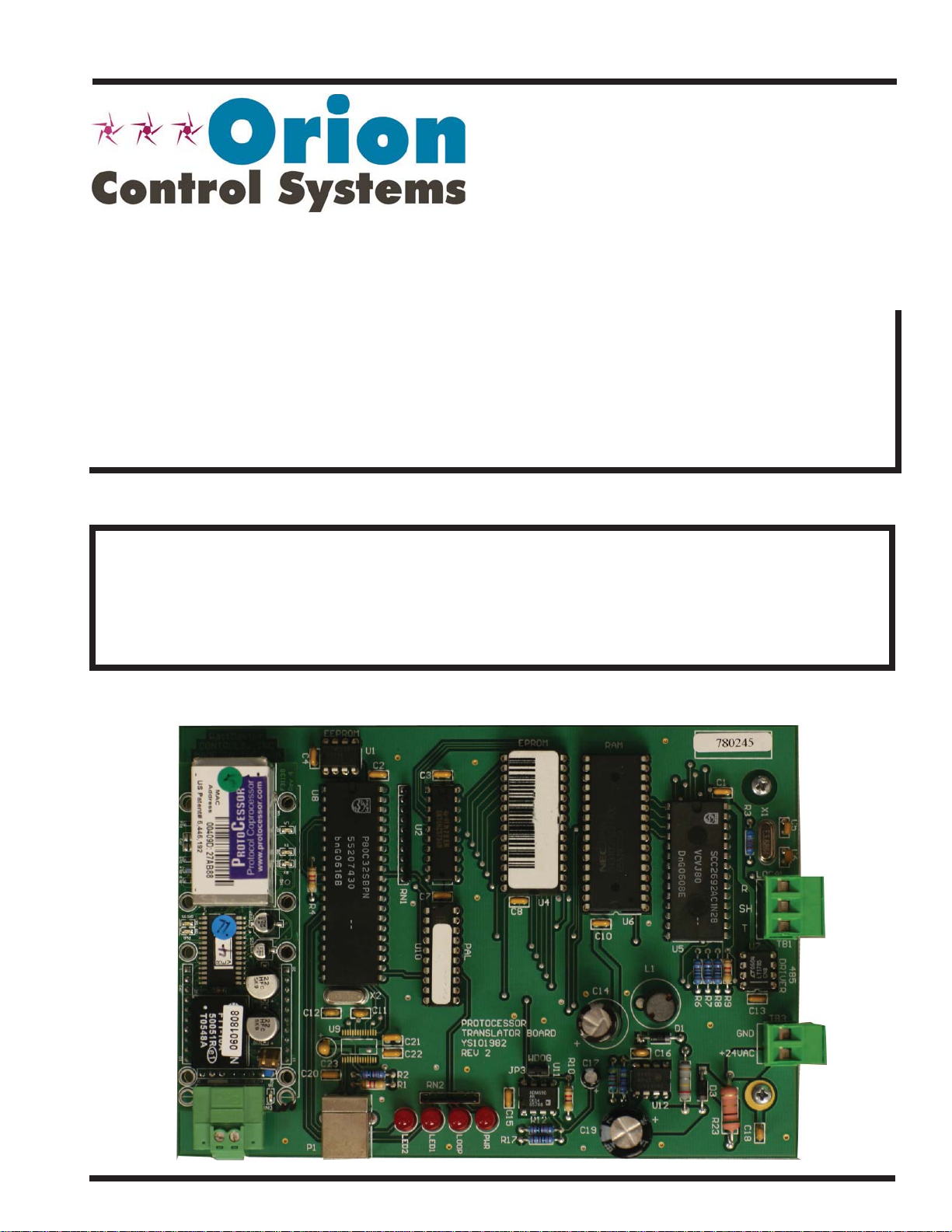
PT-Link-LON
Technical Guide
VCM-X Controller Code: SS1026 & Y200920 Version 2.0 and up;
VCM-X Modular Controller Code: SS1030 & SS1034
VCM-X WSHP Controller Code: SS1032 & SS1033
SA Controller Code: Y200921
VCM Controller Code: SS1016, Y200409, Y200616, Y200822
Page 2

Table of Contents
General Information ......................................................................................................................................... 3
Data Sharing ................................................................................................................................................................................3
Hardware Specifi cations ..............................................................................................................................................................3
Connection and Wiring Information ................................................................................................................ 4
Confi guring the PT-Link Controller .................................................................................................................. 5
PT-Link Hardware Connection .....................................................................................................................................................5
Computer IP Address Set-up for Windows 98, NT, and XP ..........................................................................................................5
Connecting to The PT-Link ...........................................................................................................................................................7
Making Changes to the Confi guration File (confi g.csv) ................................................................................................................7
Upload Confi g.csv from the PT-Link .............................................................................................................................................7
Explicit and Implicit Addressing ....................................................................................................................................................8
Troubleshooting the PT-Link Controller .......................................................................................................... 9
Download Confi g.csv to the PT-Link ..........................................................................................................................................10
PT-Link Board LEDs ...................................................................................................................................................................11
ProtoCessor Module LEDs .........................................................................................................................................................12
Using RUINET ............................................................................................................................................................................13
Verifying Proper Communications ..............................................................................................................................................13
Verifying Proper Values ..............................................................................................................................................................13
Data Arrays .................................................................................................................................................... 14
Table 2: VCM-X Modular Data Array for Field Server................................................................................................................14
Table 3: VCM-X WSHP (Tulsa) Data Array for Field Server ......................................................................................................14
Table 4: VCM-X WSHP (Coil) Data Array for Field Server ........................................................................................................15
Table 5: VCM-X Data Array for Field Server..............................................................................................................................15
Table 6: SA Controller Data Array for Field Server ....................................................................................................................16
Table 7: VCM Data Array For Field Server ................................................................................................................................16
Appendix A ..................................................................................................................................................... 17
Figure 23: RJ-45 8P8C Cable for WattMaster Cross Over Networking - WattMaster Part #HZ000136 ....................................17
Appendix B ..................................................................................................................................................... 18
External Interface Files (XIF Files) .............................................................................................................................................18
Appendix C - VCM-X Modular and VCM-X WSHP LON Parameters ............................................................... 19
Appendix D - VCM-X LON Parameters ........................................................................................................... 21
Appendix E - SA Controller LON Parameters ................................................................................................ 27
Appendix F - VCM LON Parameters ............................................................................................................... 31
WattMaster Controls, Inc.
8500 NW River Park Drive · Parkville , MO 64152
Toll Free Phone: 866-918-1100
PH: (816) 505-1100 · FAX: (816) 505-1101 · E-mail: mail@wattmaster.com
Visit our web site at www.orioncontrols.com
Form: OR-PTLNKLON-TGD-01M Copyright 2010 WattMaster Controls, Inc.
®
LON
and LONWorks® are registered trademarks of Eschelon Corporation.
WattMaster Controls, Inc. assumes no responsibility for errors, or omissions.
This document is subject to change without notice.
Page 3
PT-Link-LON® Technical Guide
PC
ROTO ESSOR
General Information
The OE368-23-LON, PT-Link-LON, provides bi-directional communication between ONE of the following types of Orion controllers—
VCM-X, SA, VCM, MUA II, or VAV/CAV:
VCM-X Controller (SS1026, SS1030, SS1032,
SS1033, SS1034, Y200920); SA Controller (Y200921)
VCM Controller (SS1016, Y200409, Y200616, Y200822)
*MUA II Controller (Y200405); VAV/CAV Controller (Y200301)
*NOTE: Documentation is available for MUA II/VAV/CAV on
our Orion Controls website: www.orioncontrols.com/
literature-new.html
NOTE: The PT-Link-LON device can be used to connect to only
one Orion controller. If more than one Orion controller is
present in a system, each one will require a PT -Link-LON
device for integration with a LON protocol network.
To determine what controller you have, you must look at the label located on the controller EPROM. If the controller label does not match
any of the SS or Y numbers listed above, your controller will not work
with the PT-Link-LON
®
.
Data Sharing
The PT-Link-LON interface provides the following data sharing capabilities:
• Provides values from points on the Orion side of the
gateway to LON® devices as if the values were
originating from LON® objects.
• Allows LON
®
devices to modify point values on the
Orion controller side of the PT-Link-LON® by using
standard LON® write services.
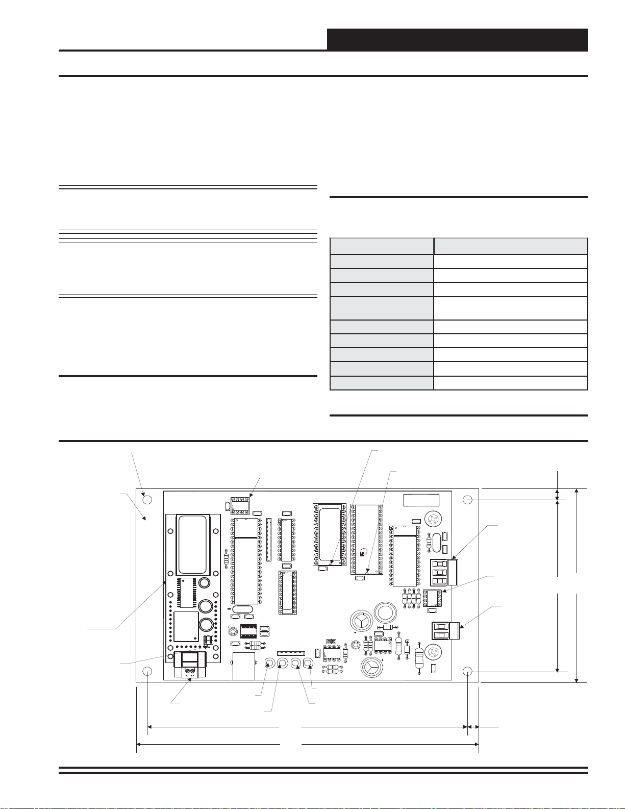
Hardware Specifi cations
Table 1 contains the hardware specifi cations for the PT-Link-LON®
interface.
Technical Data
LON® Loop
Controller Loop
Network Protocol
Protocol
(WattMaster Loop)
Power Input Voltage
Power Consumption
Operating T emp
Operating Humidity
Weight
Table 1: PT-Link-LON® Interface Technical Data
TP/FT-10 (78 Kps)
RS-485, 9600 Baud Rate
LONWorks®
HSI Open Protocol Token Passing
24 VAC
10 VA Maximum
10°F to 149°F
90% RH Non-Condensing
8 oz.
0.20 Dia.
Mounting Hole
Typ. 4 PL.
Mounting
Backplate
WattMaster
CONTROLS, INC
MADE IN THE USA
MM1
EEPROM
C4
U8
EEPROM Chip
U1
C2
EPROM
TRANSLATOR
MODULE
X2
C11
Diagnostic
LED #1
RN1
R2
R1
C21
C22
LED2
C7
U10
RN2
LED1
SF000103
PAL
PROTOCESSOR
TRANSLATORBOARD
YS101982
REV 2
LOOP
C8
WDOG
JP3
PWR
R17
Power
LED
Communications
LED
U4
U11
R12
C19
LON®Protocessor
Module
Service Pin Button
ROTO ESSOR
PC
C20
C9
®
LONWorks
Communications
Wiring Terminal
R4
C12
P1
11.0592
U9
C23
Diagnostic
LED #2
7.00"
7.50"
Figure 1: PT-Link-LON® Board Components and Dimensions
EPROM Chip
Pin 1 Indicator
RAM Chip
Pin 1 Indicator
RAM
U6
C10
C14
C17
SERIAL #
C1
X1
C6C5
LOCAL
R
SH
T
TB1
D3
R23
R9R3R8R6R7
+24VAC
U7
DRIVER
485
C13
TB3
GND
C18
U5
L1
D1
C16
U12
Local Loop
Communications
Wiring Terminal
Local Loop
Communications
Driver Chip
24 VAC Power
Terminals
0.25”
4.00”
4.50"
0.25”
PT-Link Interface 3
Page 4
PT-Link-LON® Technical Guide
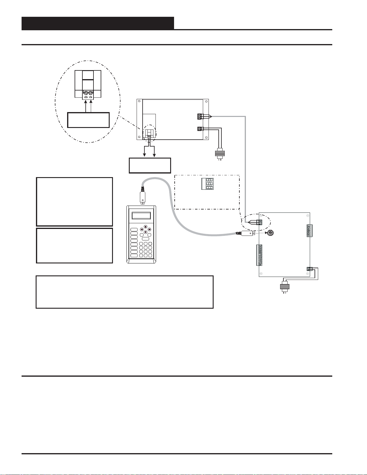
Connection and Wiring Information
®
LON Connection
®
To LON Network
Caution: The LON Network
®
Communication Terminal Block
Must Be Disconnected Before
Connecting The Modular Service
Tool. After Programming The
Controller, Disconnect
The Service Tool and Then
Reconnect The Communication
Terminal Block.
Note: All Programming Of
Controllers Must Be Done Using
The Modular Service Tool. The
Modular System Manager Should
Not Be Used On A System That
Has A PT-Link Installed.
PT- Link-LON Interface
®
LON Connection
®
To LON Network
UP
Mode
Selection
CONFIGURATION
BALANCE-TEST
STATUS
SETPOINTS
SCHEDULES
OVERRIDES
ALARMS
ON
PREV
DOWN
ESC
ENTER
13
2
708
DEC
NEXT
CLEAR
654
9
MINUS
-
Modular Service Tool
®
24 VAC
(10 VA)
Line Voltage
T
SHLD
R
Typical Terminal Blocks. All
Wiring To Be T To T, SHLD
(G) To SHLD (G)&RToR
Controller
Wiring Notes:
1.) All wiring to be in accordance with local and national electrical codes
and specifications.
2.) All communication wiring to be 18 gauge minimum, 2 conductor twisted pair with
shield. Use Belden #82760 or equivalent.
Figure 2: PT-Link-LON® Interface Wiring
24 VAC
(8 VA)
Line Voltage
4
PT-Link Interface
Page 5
PT-Link-LON® Technical Guide
Ethernet Cable
Ethernet Cable
Ethernet Hub
Connect Ethernet Cable
To Ethernet Hub Port
Connect Ethernet
Cables To Ethernet
Hub Ports
PT-Link Lon Board
Desktop Or Laptop PC
1
2
3
4
Connect Ethernet Cable To
PT-Link Ethernet Port
MADEINTHE USA
WattMaster
CONTROLS,INC
PROTOCESSOR
REV2
YS101982
PWR
LOOP
LED1
SERIAL#
TRANSLATORBOARD
DRIVER
EEPROM
PAL
RAM
EPROM
T
SH
R
LED2
+24VAC
GND
LOCAL
WDOG
TRANSLATOR
MODULE
485
U9
P1
R2
R1
C23
C22
C21
C20
C9
C18
U10
C12
C11
C2
C10
C4
C7
C8
C1
C13
C6C5
C17
C19
C16
C14
D3
D1
JP3
L1
R9R3R8R6R7
R12
R17
R23
RN1
RN2
TB3
U8
U1
U7
U11
U12
X2
X1
TB1
MM1
U6
U4
R4
U5
11.0592
SF000103
PC
ROTO ESSORPCROTO ESSOR
PC
ROTO ESSOR
Confi guring the PT-Link Controller
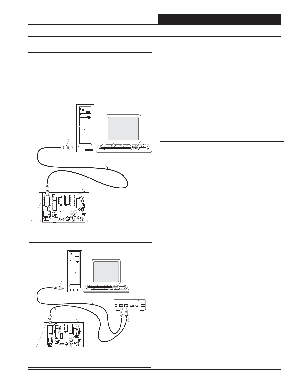
PT-Link Hardware Connection
You have two options for connecting the PT-Link to your PC via Ethernet:
1.) You may connect the PT-Link directly to your PC by using
a crossover cable (by others) as shown. See Figure 3 for
details.
2.) You can also connect both your PC and the PT-Link to an
Ethernet Hub with standard CAT5 cables. See Figure 4
for details.
Connect Ethernet
Crossover Cable Directly
To PC Ethernet Card Port
PT-Link Lon Board
EEPROM
WattMaster
CONTROLS,INC
C4
U1
MADEINTHE USA
C2
MM1
U8
TRANSLATOR
MODULE
ROTO ESSOR
R4
PC
X2
11.0592
C11
C12
U9
C23
C20
C9
P1
Connect Ethernet Crossover
Cable To PT-Link Ethernet Port
Figure 3: Connecting With Crossover Cable
Desktop Or Laptop PC
Ethernet Crossover Cable
EPROM
RAM
RN1
C7
U4
C8
SF000103
U6
C10
PAL
U10
C21
C22
R2
R1
LED2
L1
C14
PROTOCESSOR
TRANSLATORBOARD
YS101982
REV2
C16
WDOG
U11
C17
JP3
RN2
LED1
U12
R12
C19
PWR
LOOP
R17
SERIAL#
C1
X1
C6C5
LOCAL
R
SH
T
TB1
U7
U5
DRIVER
485
R9R3R8R6R7
C13
TB3
D1
GND
+24VAC
D3
R23
C18
Locate a CA T5 cable and plug one end into your computer’s Ethernet
port (use a crossover cable if connecting directly to the PT-Link).
If connecting directly, plug the other end of the Cable into the Ethernet
port on the PT -Link. If connecting through an Ethernet Hub, plug the
other end of the PC cable into the hub, and use a second CAT5 cable
to connect the PT-Link to the hub as well.
Power up the PT-Link by plugging in the power cable. The PT-Link
may take up to three minutes to power up completely. Once the PTLink is powered up, you should notice that the green “GPI05” LED
light on the ProtoCessor Board remains on continuously. See Figur e
19 on page 12 for a diagram showing the location of the ProtoCessor
“GPI05” LED.
Computer IP Address Set-up for
Windows 98, NT, and XP
In order for the PT -Link to communicate properly, it is imperative to
set the IP address of both the PT-Link as well as the computer to be
within the same netmask. You need to change the IP address on your
computer. The following instructions will explain how to confi gure
the IP address for Microsoft
NT and XP computers.
Computer IP Address Set-up for
Windows 98
1.) From the Windows START button select Start->
Setting->Control panel.
2.) Double click on the Network icon.
3.) In the Confi guration window, select the TCP/IP entry.
4.) Select Properties and go to the IP Address tab.
®
Windows 98 and Microsoft® Windows
PT-Link Interface
Figure 4: Connecting With Ethernet Cable & Hub
5.) Select Specify an IP address and then enter the
following information:
a.) IP Address 192.168.1.5
b.) Netmask 255.255.255.0
6.) Select OK until the network confi guration program exits.
7.) You might have to reboot the computer before the IP
address is valid.
5
Page 6
PT-Link-LON® Technical Guide
Confi guring the PT-Link Controller
Computer IP Address Set-up for Windows
NT or XP
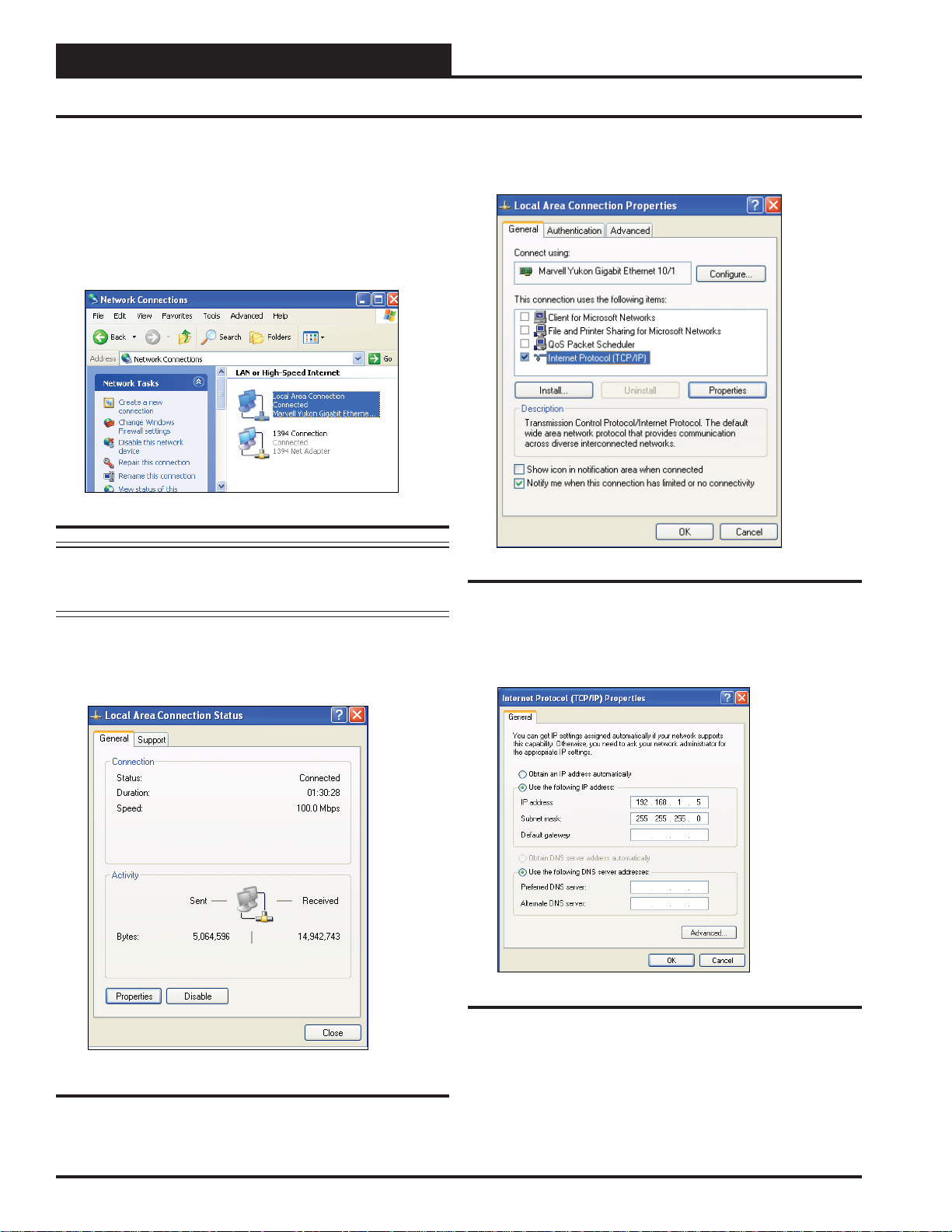
1.) Click <start>; then click <Control Panel>.
2.)
Double-click on the Network Connections icon.
The Network Connections Window will appear.
Figure 5: Network Connections Window
NOTE: If any wireless connections are listed, disable them
by
right-clicking the connection and selecting
<Disable>.
3.) In the Network Connections window, select the Local
Area Connections entry. The Local Area Connection Status
Window will appear.
4.) Click <Properties> in the lower left of the window.
The Local Area Connection Properties window will appear.
Figure 7: Local Area Connection Properties Window
5). In the Connection Items list box, be sure the Internet
Protocol (TCP/IP) is checked. Select the Internet Protocol
(TCP/IP) item to highlight it and then
The Internet Protocol Properties window will appear.
click <Properties>.
Figure 6: Local Area Connection Status Window
6
Figure 8: Internet Protocol Properties Window
6).
Type in the following information:
a.) IP address 192.168.1.5
b.) Subnet mask 255.255.255.0
c.) Default Gateway is blank
7.)
Select <OK> until all of the above network confi guration
windows are closed. You may have to
before the new values are valid.
PT-Link Interface
reboot the computer
Page 7
PT-Link-LON® Technical Guide
Confi guring the PT-Link Controller
Connecting To The PT-Link
In order to communicate and program the PT-Link you will need to
install RUINET software on your computer. If you do not have the
software, it is available for downloading at www.orioncontrols.com in
the software area of the web site. After installing the software, proceed
with the following instructions.
WARNING: Make sure to load RUINET onto your hard drive
and run the program from your hard drive. DO NOT under any
circumstances run RUINET from your cd drive.
If RUINET is in the desktop directory (if it isn’t, locate its directory),
double-click on RUINET , and the RUINET program should run. If you
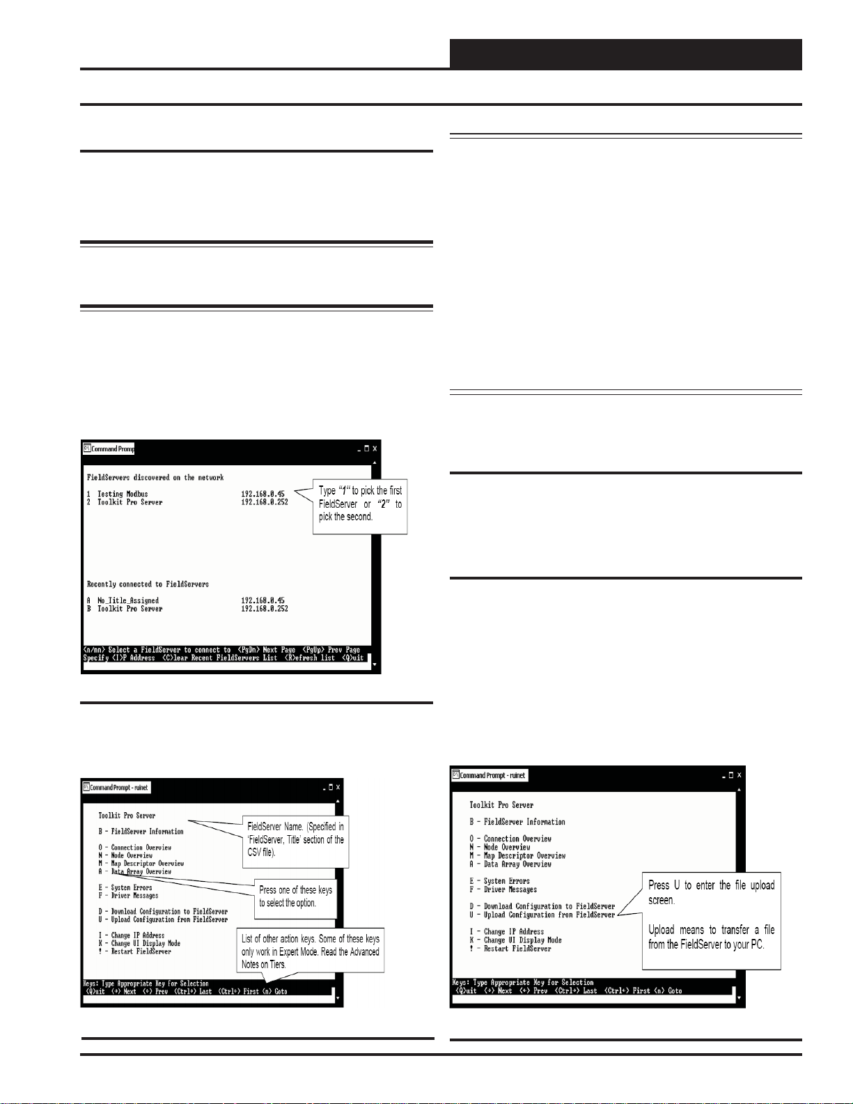
have only one PT-Link connected to the network, then RUINET will
automatically connect to that particular PT -Link; otherwise, a menu will
appear to allow the selection of the desired PT-Link.
This menu will look similar to the one shown in Figure 9.
Note: If RUINET is unable to establish a connection, there
are a few simple procedures you can perform to try to
determine the problem. To verify your network cables,
observe the “Yellow” LED displayed below “Ethernet
Connection” on the PT-Link’s ProtoCessor Module.
This LED should be on if the 10 BaseT cable is good.
Secondly, observe the “Green” LED below “Ethernet
Connection”. This LED should be solid while RUINET
is running. If the LEDs are lit as expected, and RUINET
still does not receive replies, then the netmask is probably incorrect. If this does not help, then your Ethernet
setup on your PC is possibly not compatible. Ensure that
you have an Ethernet adapter installed in your software
confi guration and that it is confi gured to run the TCP/IP
protocol. If you are still unable to connect, please contact
WattMaster Controls, Inc.
Making Changes to the Confi guration
File (confi g.csv)
To make changes to the confi guration fi le on the PT-Link, use the pro-
cedures outlined that follow — Upload, Address, Poll, and Download
the Confi guration File.
Figure 9: RUINET PT-Link Selection Menu
Select the required PT-Link by typing the Number or Letter in the left
hand column. You should now have a menu that looks like Figure 10.
You are now ready to send and receive fi les to and from the PT-Link.
Upload Confi g.csv from the PT-Link
The PT-Link contains a confi guration fi le (confi g.csv) that includes
information such as addressing. This fi le can be uploaded from the
PT-Link for modifi cation if needed. The PT-Link also contains an
external interface fi le otherwise called an XIF fi le (fserver.xif). The
XIF fi le includes information such as SNVT names and LON network
information. This fi le can be uploaded for use with LON programming
software. When uploaded, these fi les can be located in the same directory
that the RUINET executable fi le is stored and run from. Be sure when
uploading that the correct fi le is specifi ed in the upload window. Refer
to Figures 11 & 12 for screen details. Refer to Appendix B for details
on uploading XIF fi les.
Figure 10: RUINET PT-Link Main Menu
PT-Link Interface
Figure 11: RUINET PT-Link Main Menu - Upload
7
Page 8
PT-Link-LON® Technical Guide
Confi guring the PT-Link Controller
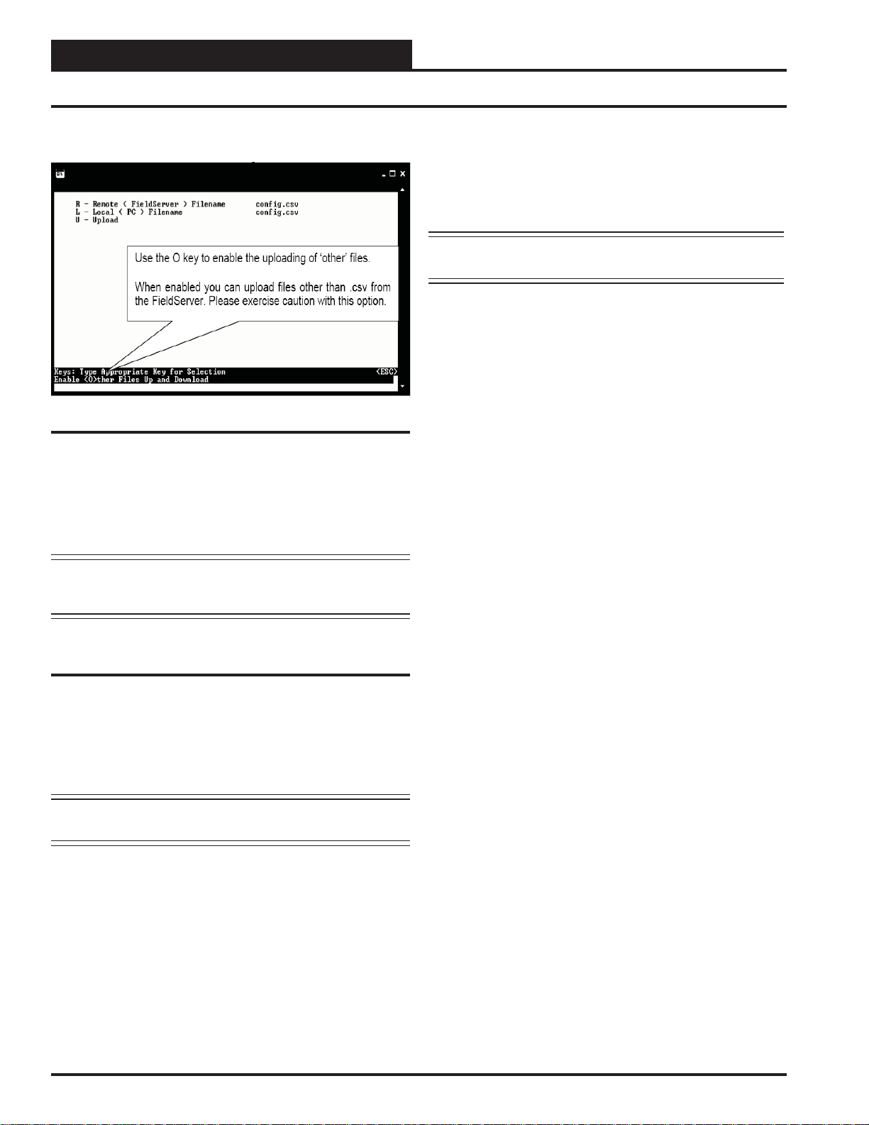
From the Main Menu, type “U”. The menu shown in Figure 12 will appear .
Figure 12: RUINET PT-Link Uploading Files
1.) Begin the upload by pressing “U.”
2.) When the upload is completed, open the uploaded fi le with
Microsoft® Notepad. This program is supplied with
Microsoft® Windows. Type “N” to open using Notepad.
Implicit Addressing Commissioning Using
LonMaker
1.) Ensure that the correct fi rmware and latest confi guration is
loaded on the PT-Link-LON.
NOTE: Each change in the PT-Link-LON requires re-commis-
sioning of the PT-Link-LON in LonMaker.
2.) Ensure that the PT-Link-LON and the LonMaker machine
are on the same network.
3.) Open the existing Network in LonMaker or create a new
Network.
4.) Click on “Create New Network” and follow the network
wizard, making the following selections:
Network Interface: Choose Network Attached
Management Mode: Choose Onnet unless you are
working offl ine
Registered Plug-ins required: None
5.) Once Visio is open with the Network showing, drag a new
device onto the drawing from the toolbox.
WARNING: Only edit the confi g.sys fi le using Notepad. Do
not use Excel. Using Excel to edit the confi g.sys fi le will corrupt
its contents!
Explicit and Implicit Addressing
Clients can address the PT-Link using explicit or implicit addressing.
Clients using explicit addressing obtain their data transfer parameters
directly from the PT -Link-LON confi guration fi le (confi g.csv). Implicit
addressing is used when a Network Management T ool such as LonMaker®
is used to connect a PT-Link-LON to other LonWorks nodes—the
PT-Link-LON is assigned its data transfer (binding) parameters by the
Network Management Tool.
NOTE: The PT-Link-LON is confi gured from the factory to use
implicit addressing.
Implicit Addressing — Network Manager assigns addresses for
communication and ensures (via address tables in the devices) that
communication connections are known.
Explicit Addressing — Device knows the address of the point in
the remote device and communicates directly without the assistance of
the Network Manager.
6.) Follow the Device Network, making the following
selections:
Enter Device Name: Choose commission device
Specify Device Template: Choose upload from device
Specify Device Channel: Choose Auto Detect
Specify Device Properties: Leave as is (Ping is optional)
Identify Device: Choose service pin
Device Application Image: Leave unchecked
Initial State: Leave as is
7.) Press the service pin on the PT-Link-LON when asked to
do so, and the PT-Link-LON will be commissioned.
8.) Drag a new function block onto the drawing from the
toolbox. Give the function block a name and ensure that it
is allocated to the PT-Link-LON device.
9.) Once the function block is on the drawing, you can drag
input and output variables onto the function block. When
you do this, LonMaker will show you the variables
avail able for binding. Click on the variables you require
(or use the select “all” option), and they will be
commissioned onto the function block.
10.) You are now ready to connect these variables to other
devices by dragging connections from the toolbox and
connecting the variables.
8
PT-Link Interface
Page 9
Troubleshooting the PT-Link Controller
Explicit Addressing & Domain Table Setup
To use explicit addressing, the client needs to change the factory settings
contained in the PT-Link-LON’s confi guration fi le (confi g.csv). The
following are the steps to change the confi guration fi le from implicit to
explicit addressing:
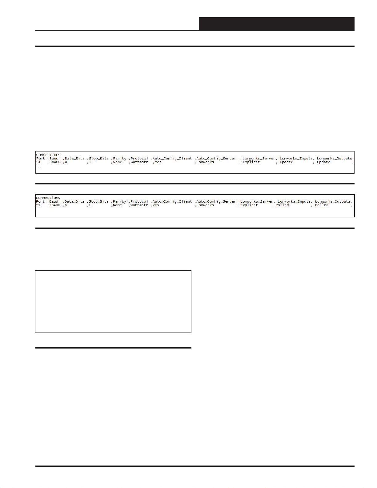
1.) Upload and open the confi g.csv fi le.
2.) Locate the “Connections” section.
3.) Locate the “Lonworks_Server” column and change the
value from “Implicit” shown in Figure 13 to “Explicit”
shown in Figure 14. You should also change the “Lon
works _Input” and “Lonworks_Outputs” from Update to
Polled.
Figure 13: PT-Link-LON Implicit Confi guration
PT-Link-LON® Technical Guide
Figure 14: PT-Link-LON Explicit Confi guration
In addition, the PT-Link-LON must have its domain, subnet, and node
IDs set. This feature is enabled in the confi guration fi le by fi lling out
the Title and System_Address fi elds of the PT-Link-LON parameters
as follows:
//==================================================
//
// Common Information
//
Bridge
System_Address ,Title
23 ,”:D48:S01:Wattmaster Explicit Lon v1.00d”
Figure 15: PT-Link-LON Domain and Subnet Setting
The Title fi eld must start with “:D”, followed by the domain_id in
hexadecimal notation, followed by “:S”, followed by the subnet_id in
hexadecimal notation, and enclosed by “:”. The domain length is automatically determined by the number of digits in the [domain_id] fi eld.
With 2 hexadecimal digits constituting 1 byte, “:D123456:”, for example,
would have a length of 3.
Once the domain table has been set, the “:Dxx:Sxx:” part of the Title
fi eld will be removed.
Now the Title fi eld will be left with [Title continued…] which may be
the Node self documentation string or any title.
After the changes are done, do not forget to save the fi le, download
the new confi guration fi le, and restart the PT-Link-LON. Refer to the
Download Section that follows.
PT-Link Interface
9
Page 10
PT-Link-LON® Technical Guide
Troubleshooting the PT-Link Controller
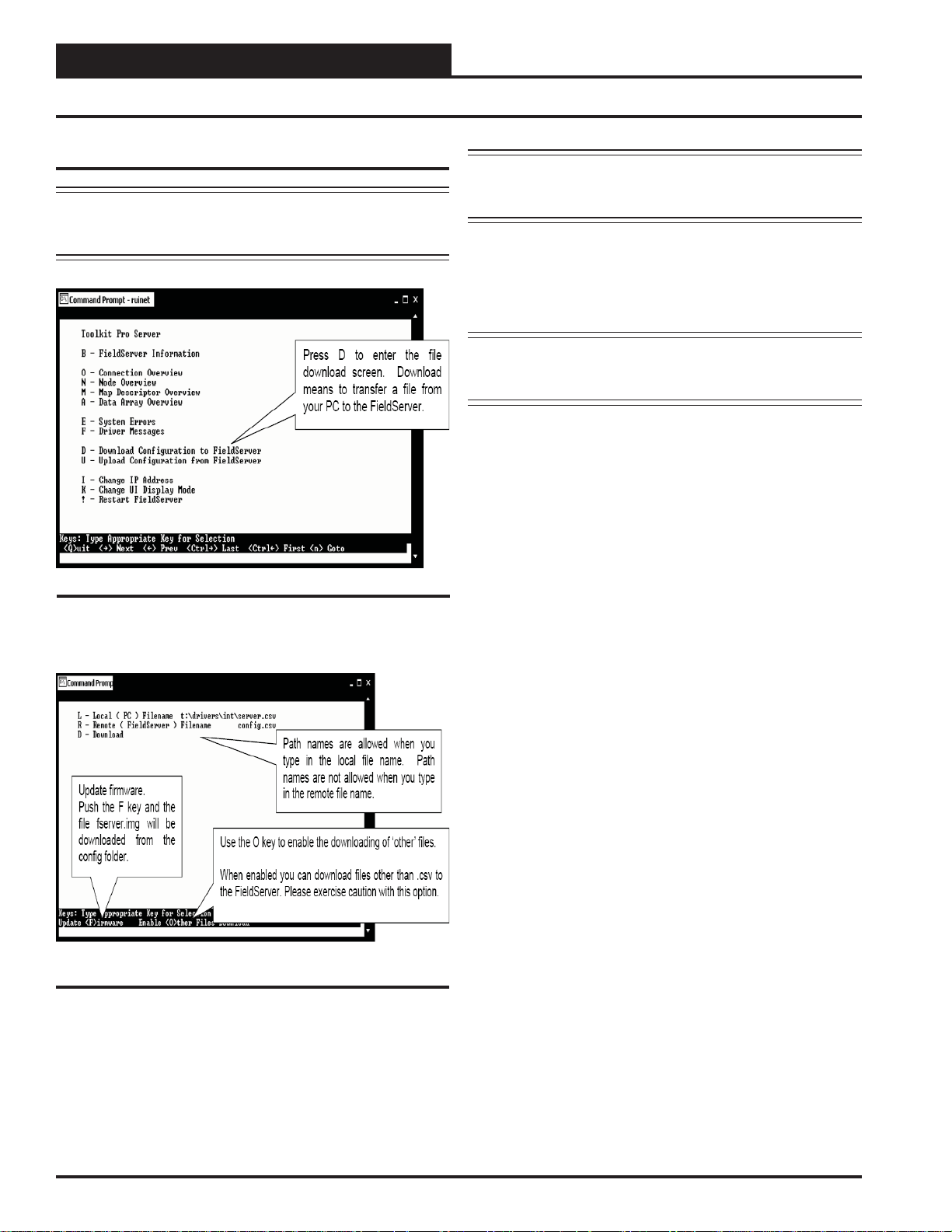
Download Confi g.csv to the PT-Link
NOTE: Before attempting to send fi les to the PT -Link, make sure
that these fi les are in the same directory as the RUINET
utility being used for sending.
Figure 16: RUINET PT-Link Main Menu - Download
NOTE: The utility will indicate when downloading is complete.
DO NOT reset the PT-Link until this message is displayed, as this will corrupt the PT-Link.
2.) Once the download is complete, push <Esc> to get back to
the main menu and use the “!” option (or simply cycle
power to the PT-Link) to put the new fi le into operation.
It is possible to do multiple downloads to the PT-Link
before resetting it.
NOTE: The Remote Filename option must always be named
“confi g.csv” for confi gurations; otherwise, they will be
ignored by the PT-Link.
From the Main Menu, type “D”. The menu shown in Figure 17 will appear .
Figure 17: RUINET PT-Link Downloading Files
1.) Begin the download by selecting “D.”
10
PT-Link Interface
Page 11
PT-Link-LON® Technical Guide
Troubleshooting the PT-Link Controller
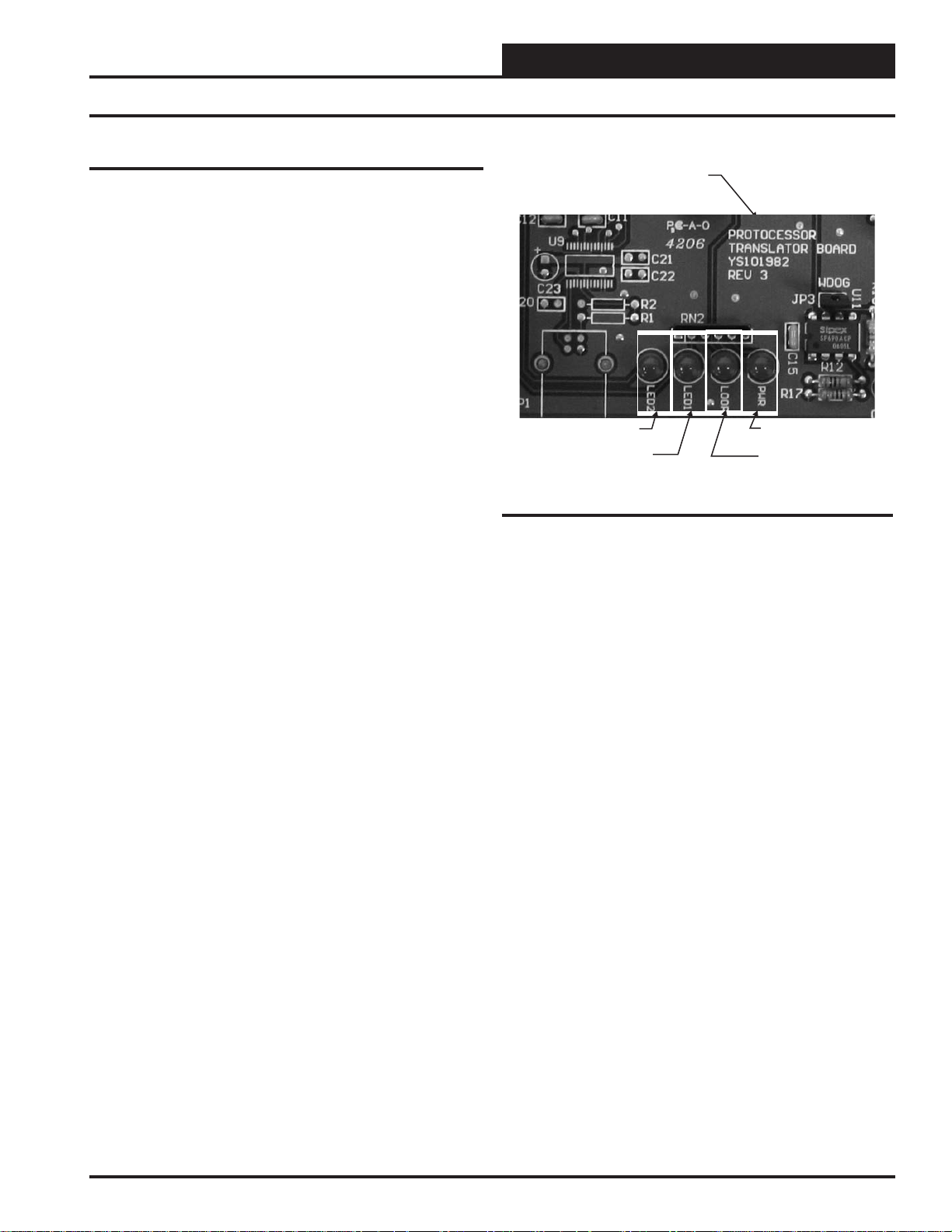
PT-Link Board LEDs
The PT -Link-LON® is equipped with LEDs that can be used for troubleshooting. There are four LEDs on the PT -Link board. See Figur e 18 for
the locations of the LEDs on the PT-Link board. The LED descriptions
and functions are listed in the following paragraphs.
PWR LED
When the PT -Link-LON® is powered up, the “PWR” LED should light
up and stay on continuously. If it does not light up, check to be sure
that you have 24 VAC connected to the board, that the wiring connections are tight, and that they are wired for correct polarity. The 24 VAC
power must be connected so that all ground wires remain common. If
after making all these checks the “PWR” LED still does not light up,
please contact WattMaster Controls Technical Support at our Toll Free
number—866-918-1100—for assistance.
LOOP LED
When power is applied to the PT-Link-LON
also light up. The LED should fl icker rapidly, indicating that the PT -Link
is trying to communicate with the controllers on the loop. A “fl icker”
is defi ned as a brief moment when the LED turns off and back on. If the
“LOOP” LED does not operate as indicated above, fi rst power down
the unit and then reapply power. If this does not work, please contact
W attMaster Controls Technical Support at our Toll Free number—866918-1100—for assistance.
®,
the “LOOP” LED will
PT-Link Base
Board
LED2
LED1
Figure 18: PT-Link-LON® LED Locations
PWR
LOOP
LED 1
When power is fi rst applied, “LED 1” will be off temporarily and then
will blink once if it is communicating with the controller. If the LED
is not blinking, there is a communication problem between the HVAC
controller and the PT-Link board. The “COMM” LED on the HVAC
controller also should be solid and will fl icker occasionally indicating
communication with the PT-Link-LON
not fl icker, then there is no communication between the PT Link and
the controller.
®
. If the “COMM” LED does
LED 2
When power is fi rst applied, “LED 2” will be off temporarily and then
will blink slowly indicating that the PT -Link baseboard is communicating
with the Protocessor Module. If “LED 2” does not blink, check that the
Protocessor Module is installed correctly in the PT-Link baseboard.
PT-Link Interface
11
Page 12
PT-Link-LON® Technical Guide
Troubleshooting the PT-Link Controller
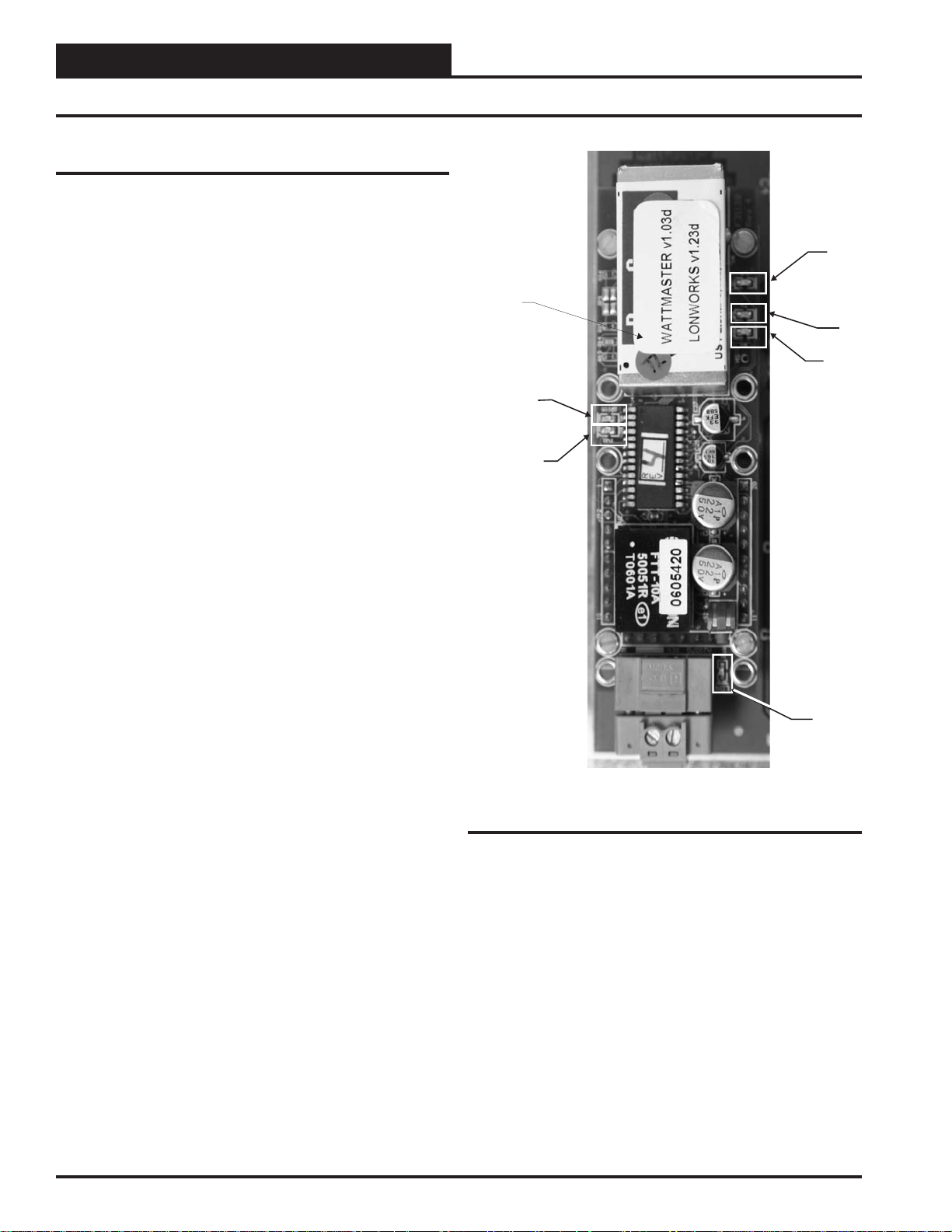
ProtoCessor Module LEDs
PWR LED
When the PT -Link is fi rst powered up, the “PWR” LED should light up
and stay on continuously. See Figure 19. If the LED doesn’t light up,
check that the ProtoCessor is installed correctly and fi rmly connected
to the Base Board.
Protocessor
GPI05 LED
The “GPI05” LED will light up when the Base Board and the ProtoCessor Module have established communications. This can take up to 3
minutes depending on the number of units connected to the PT -Link. If
it fails to light up after 3 minutes, check that the ProtoCessor is installed
correctly and fi rmly to the Base Board.
LON LED
When the unit is fi rst powered up, before commissioning has occurred,
this LED will be blinking to indicate the unit has not been commissioned yet. Once the unit is commissioned, the LED will stay off during
normal operations.
LON
GPI05
LA
TX
RX
PWR
LA LED
When the unit is fi rst powered up, this LED should be blinking constantly .
If this LED is constantly on or constantly off, the Module is not working
properly and needs to be replaced.
TX & RX LEDs
These LEDs work together to indicate that communication is being
established with the desired protocol network. If both LEDs are blinking, then communication is working properly. If both are not blinking,
check the protocol network wiring.
If all of these tests are made and the controller still doesn’t operate,
please contact WattMaster Controls Technical Support at our Toll Free
number—866-918-1100—for assistance.
LON
Figure 19: PT-Link-LON® LED Locations
12
PT-Link Interface
Page 13

Troubleshooting the PT-Link Controller
Using RUINET
Before continuing with the troubleshooting, make sure the PT-Link is
connected correctly and the RUINET software is installed, running, and
functioning correctly.
Verifying Proper Communications
From the Main Screen, press “O” to go the Connection Overview
Screen. This screen supplies information on communication between the
PT-Link and remote devices. A number of aspect screens are available,
and some of the aspect screens have more than one page. Use the space
bar to toggle between aspects and use the <PgUp> and <PgDn> keys
to toggle between pages of the same aspect. The Connection Overview
and Settings Aspect Screen is shown in Figure 20.
The main purpose in this screen is to verify that messages and characters
are being transmitted and received. In addition, it shows the number of
communication errors. If the PT-Link connection “03” is the protocol
connection, verify that is communicating appropriately. If it is not, check
that the PT -Link LEDs are working properly , the unit is wired correctly ,
and the PT-Link is confi gured correctly (Baud Rate, Unit Address &
MAC Address). If the number of errors is constantly increasing, move
to the Error Screen by pressing the <Space Bar> 3 times to fi nd out
the cause of the errors. Use the <PgUp> and <PgDn> keys to toggle
between pages of the Error Screen.
PT-Link-LON® Technical Guide
Figure 20: Connection Overview Screen
Verifying Proper Values
To verify that the correct values for each unit are being communicated
to the PT-Link, move to the Data Array Overview Screen. To get to
the screen, press “A” from the Main Menu. See Figure 21 for screen
details.
In the Data Array Overview Screen (Figure 21) you will be able to
see the data arrays of all the units connected to the PT -Link denoted by
an array name “DA_XXX_IY”—Y being the address of the unit minus
one. The Address of the unit is determined by a set of dip switches.
To view the values being communicated from a specifi c unit, move to
the Data Array Detail Screen (Figure 22) of the unit by entering the
number under which it is listed. For example, for the unit listed in the
third position, enter “03”.
To understand what each value means, look at the Data Array T ables for
the desired unit type, VA V/CAV, MUA II, or VCM. You can change the
writable values from this screen by using the modify command. T o use
the modify command press “M” from the Data Array Detail Screen
and then enter the Offset you want to change followed by a space and
the new value. Example: To change the Cooling Supply Setpoint to 60
in the VAV/CAV, press “M”, enter “58 60”, and then press <Enter>.
This could be useful to prove that the unit can take and keep the setpoints properly.
Figure 21: Data Array Overview Screen
PT-Link Interface
Figure 22: Data Array Detail Screen
13
Page 14

PT-Link-LON® Technical Guide
Data Arrays
VCM-X Modular Data Array For Field Server
Offset 01234567
0
8
16
24
32
40
48
56
64
72
80
88
96
104
AppVer ClSt HtSt OaWtbl TpDmnd SpcTp SaTp RaTp
OaTp DuctPr OaRh UnitMode CtrlSts ClEnbl HtEnbl EcoEnbl
FanDly PofCfg CO2Cfg MdHt2Ins Rt2Ins OnRlys ExRlys12 ExRlys34
EcoPos VfdBwPos VfdExPos AlrmSts AlrmGrp1 AlrmGrp2 AlrmGrp3 SaTpAlm
OaTpAlm SpcTpAlm MchClAlm MchHtAlm PofAlm DrtFAlm SmokeAlm LoSaAlm
HiSaAlm CtrlTpCF CtrlTpHF CtrlTp InRh InRhStM DptStM MdClPos
MdHtPos MdHt2Pos Rt2Pos OcpClSt OcpHtSt UnClOst UnHtOst WtblSt
SaClSt SaHtSt WmupSt SpcTpOst SaTpOst RaTpOst OaTpOst CoilTpSt
DptSt InRhSt DuctPrSt RfPrSt SchdFrc OnRly1 OnRly2 OnRly3
OnRly4 OnRly5 ExRly1 ExRly2 ExRly3 ExRly4 ExRly5 ExRly6
ExRly7 ExRly8 ExRly9 ExRly10 ExRly11 ExRly12 ExRly13 ExRly14
ExRly15 ExRly16 CO2St MinEcoSt CO2Level ByPasDmp RaDmp RfPr
OaDwpt CoilTp SaTpStM PreHtSp OaCFM EtCFM SaCFM OACfmSt
OACfmRs OACfmStM MdCmp2 HdPr1 HdPr2 CdFan1 CdFan2 –
Table 2: VCM-X Modular Data Array For Field Server
VCM-X WSHP (Tulsa) Data Array For Field Server
Offset 01234567
0
8
16
24
32
40
48
56
64
72
80
88
96
104
112
120
AppVer ClSt HtSt OaWtbl TpDmnd SpcTp SaTp RaTp
OaTp DuctPr OaRh UnitMode CtrlSts ClEnbl HtEnbl EcoEnbl
FanDly PofCfg CO2Cfg MdHt2Ins Rt2Ins OnRlys ExRlys12 ExRlys34
EcoPos VfdBwPos VfdExPos AlrmSts AlrmGrp1 AlrmGrp2 AlrmGrp3 SaTpAlm
OaTpAlm SpcTpAlm MchClAlm MchHtAlm PofAlm DrtFAlm SmokeAlm LoSaAlm
HiSaAlm CtrlTpCF CtrlTpHF CtrlTp InRh InRhStM DptStM MdClPos
MdHtPos MdHt2Pos Rt2Pos OcpClSt OcpHtSt UnClOst UnHtOst WtblSt
SaClSt SaHtSt WmupSt SpcTpOst SaTpOst RaTpOst OaTpOst CoilTpSt
DptSt InRhSt DuctPrSt RfPrSt SchdFrc OnRly1 OnRly2 OnRly3
OnRly4 OnRly5 ExRly1 ExRly2 ExRly3 ExRly4 ExRly5 ExRly6
ExRly7 ExRly8 ExRly9 ExRly10 ExRly11 ExRly12 ExRly13 ExRly14
ExRly15 ExRly16 CO2St MinEcoSt CO2Level ByPasDmp RaDmp RfPr
OaDwpt CoilTp SaTpStM PreHtSp OaCFM EtCFM SaCFM OACfmSt
OACfmRs OACfmStM MdCmp2 HdPr1 HdPr2 CdFan1 CdFan2 WaterTpA
WaterTpB A1LSPAlm A1LktAlm A2LSPAlm A2LktAlm B1LSPAlm B1LktAlm B2LSPAlm
B2LktAlm LWT1Alm LWT2Alm POWF1Alm POWF2Alm ComMAlm – –
Table 3: VCM-X WSHP (Tulsa) Data Array For Field Server
14
PT-Link Interface
Page 15

PT-Link-LON® Technical Guide
Data Arrays
VCM-X WSHP (Coil) Data Array For Field Server
Offset 01234567
0
8
16
24
32
40
48
56
64
72
80
88
96
104
112
AppVer ClSt HtSt OaWtbl TpDmnd SpcTp SaTp RaTp
OaTp DuctPr OaRh UnitMode CtrlSts ClEnbl HtEnbl EcoEnbl
FanDly PofCfg CO2Cfg MdHt2Ins Rt2Ins OnRlys ExRlys12 ExRlys34
EcoPos VfdBwPos VfdExPos AlrmSts AlrmGrp1 AlrmGrp2 AlrmGrp3 SaTpAlm
OaTpAlm SpcTpAlm MchClAlm MchHtAlm PofAlm DrtFAlm SmokeAlm LoSaAlm
HiSaAlm CtrlTpCF CtrlTpHF CtrlTp InRh InRhStM DptStM MdClPos
MdHtPos MdHt2Pos Rt2Pos OcpClSt OcpHtSt UnClOst UnHtOst WtblSt
SaClSt SaHtSt WmupSt SpcTpOst SaTpOst RaTpOst OaTpOst CoilTpSt
DptSt InRhSt DuctPrSt RfPrSt SchdFrc OnRly1 OnRly2 OnRly3
OnRly4 OnRly5 ExRly1 ExRly2 ExRly3 ExRly4 ExRly5 ExRly6
ExRly7 ExRly8 ExRly9 ExRly10 ExRly11 ExRly12 ExRly13 ExRly14
ExRly15 ExRly16 CO2St MinEcoSt CO2Level ByPasDmp RaDmp RfPr
OaDwpt CoilTp SaTpStM PreHtSp OaCFM EtCFM SaCFM OACfmSt
OACfmRs OACfmStM MdCmp2 HdPr1 HdPr2 CdFan1 CdFan2 WaterTpA
A1LSPAlm A1LktAlm B1LSPAlm B1LktAlm LWT1Alm POWF1Alm ComMAlm –
Table 4: VCM-X WSHP (Coil) Data Array For Field Server
VCM-X Data Array For Field Server
Offset 01234567
0
8
16
24
32
40
48
56
64
72
80
88
96
104
AppVer ClSt HtSt OaWtbl TpDmnd SpcTp SaTp RaTp
OaTp DuctPr OaRh UnitMode CtrlSts ClEnbl HtEnbl EcoEnbl
FanDly PofCfg CO2Cfg MdHt2Ins Rt2Ins OnRlys ExRlys12 ExRlys34
EcoPos VfdBwPos VfdExPos AlrmSts AlrmGrp1 AlrmGrp2 AlrmGrp3 SaTpAlm
OaTpAlm SpcTpAlm MchClAlm MchHtAlm PofAlm DrtFAlm SmokeAlm LoSaAlm
HiSaAlm CtrlTpCF CtrlTpHF CtrlTp InRh InRhStM DptStM MdClPos
MdHtPos MdHt2Pos Rt2Pos OcpClSt OcpHtSt UnClOst UnHtOst WtblSt
SaClSt SaHtSt WmupSt SpcTpOst SaTpOst RaTpOst OaTpOst CoilTpSt
DptSt InRhSt DuctPrSt RfPrSt SchdFrc OnRly1 OnRly2 OnRly3
OnRly4 OnRly5 ExRly1 ExRly2 ExRly3 ExRly4 ExRly5 ExRly6
ExRly7 ExRly8 ExRly9 ExRly10 ExRly11 ExRly12 ExRly13 ExRly14
ExRly15 ExRly16 CO2St MinEcoSt CO2Level ByPasDmp RaDmp RfPr
OaDwpt CoilTp SaTpStM PreHtSp OaCFM EtCFM SaCFM OACfmSt
OACfmRs OACfmStM ––––––
Table 5: VCM-X Data Array For Field Server
PT-Link Interface
15
Page 16

PT-Link-LON® Technical Guide
Data Arrays
SA Controller Data Array For Field Server
Offset 01234567
0
8
16
24
32
40
48
56
64
72
80
88
AppVer ClSt HtSt TpDmnd SpcTp SaTp DuctPr UnitMode
CtrlSts ClEnbl HtEnbl EcoEnbl FanDly MdHt2Ins Rt2Ins EcoPos
VfdBwPos SaTpAlm SpcTpAlm MchClAlm MchHtAlm PofAlm DrtFAlm LoSaAlm
HiSaAlm CtrlTpCF CtrlTpHF CtrlTp InRh InRhStM DptStM MdClPos
MdHtPos MdHt2Pos Rt2Pos OcpClSt OcpHtSt UnClOst UnHtOst SaClSt
SaHtSt WmupSt SpcTpOst SaTpOst CoilTpSt DptSt InRhSt DuctPrSt
SchdFrc OnRly1 OnRly2 OnRly3 OnRly4 OnRly5 ExRly1 ExRly2
ExRly3 ExRly4 ExRly5 ExRly6 ExRly7 ExRly8 ExRly9 ExRly10
ExRly11 ExRly12 ExRly13 ExRly14 ExRly15 ExRly16 CoilTp SaTpStM
PreHtSp EaTp EwTp EaRH HdPr1 HdPr2 CoilTp2 EaDpt
WSEByp WSEByp2 MdCmp2 CoilTpSt CdPos1 CdPos2 EaTpAlm EmerAlm
PoWFAlm DrnAlm EaTpOst EwTpOst ––––
Table 6: SA Controller Data Array For Field Server
VCM Data Array For Field Server
Offset 01234567
0
8
16
24
32
40
48
56
64
72
80
88
96
AppVer ClSt HtSt OaWtbl TpDmnd SpcTp SaTp RaTp
OaTp DuctPr OaRh UnitMode CtrlSts ClDmnd HtDmnd DehmDmnd
ClEnbl HtEnbl EcoEnbl FanDly WmupDmnd PofCfg CO2Cfg MdHt2Ins
Rt2Ins OnRlys ExRlys12 ExRlys34 EcoPos VfdBwPos VfdExPos AlrmSts
AlrmGrp1 AlrmGrp2 AlrmGrp3 SaTpAlm OaTpAlm SpcTpAlm MchClAlm MchHtAlm
PofAlm DrtFlAlm SmokeAlm LoSaAlm HiSaAlm CtrlTpCF CtrlTpHF CtrlTp
InRh InRhStM DptStM MdClPos MdHtPos MdHt2Pos Rt2Pos OcpClSt
OcpHtSt UnClOst UnHtOst WtblSt SaClSt SaHtSt WmupSt SpcTpOst
SaTpOst RaTpOst OaTpOst CoilTpSt DptSt InRhSt DuctPrSt RfPrSt
SchdFrc OnRly1 OnRly2 OnRly3 OnRly4 OnRly5 ExRly1 ExRly2
ExRly3 ExRly4 ExRly5 ExRly6 ExRly7 ExRly8 ExRly9 ExRly10
ExRly11 ExRly12 ExRly13 ExRly14 ExRly15 ExRly16 CO2St MinEcoSt
CO2Level ByPasDmp RaDmp RfPr OaDwpt CoilTp SaTpStM PreHtSp
Table 7: VCM Data Array For Field Server
16
PT-Link Interface
Page 17

PT-Link-LON® Technical Guide
Appendix A
Brown/White
White/Brown
Orange/White
White/Blue
Blue/White
White/Orange
RJ-45 Connector as viewed
from the bottom side
8
7
6
5
4
3
Use the standard EIA/TIA color code for "CROSS OVER CABLE" as shown.
It is the same as a standard Cat 5 patch cabling. The outer cable jacket should
not
Be "Orange" in color. This is a straight thru pin 1 to pin 1 cable.
not
RJ-45 Connector as viewed
from the bottom side
White/Orange
1
Orange/White
2
White/Green
3
Blue/White
4
White/Blue
5
Green/White
6
Figure 23: RJ-45 8P8C Cable for WattMaster Cross Over Networking - WattMaster Part #HZ000136
PT-Link Interface
17
Page 18

PT-Link-LON® Technical Guide
Appendix B
External Interface Files (XIF Files)
At start-up the PT-Link-LON creates an external interface fi le (XIF)
called fServer.xif based on the information contained in the PT-LinkLON’s confi guration fi le (confi g.csv). The PT-Link-LON’ s confi guration
can be changed by uploading and editing the confi g.csv fi le; therefore,
the XIF fi le must be obtained by uploading it from the PT-Link-LON.
The recommended procedure for obtaining the XIF fi le for the PT -Link-
LON is to upload it. Remember that this XIF fi le will change whenever
the confi guration fi le has been changed and downloaded and the PT-
Link-LON restarted. The following are the steps to extract the external
interface fi le (XIF) from the PT-Link-LON:
1.) Start RUINET application.
2.) Select Fieldserver option “1” (this step may be skipped
when application auto detects PT Link).
3.) In the Main Menu select “A” – Data Array Overview.
4.) You should see 2 array items that are labeled wattmstr dump and wattmstr-stats. Ignore these.
5.) You should see 2 additional arrays for the controller
connected.
Example: DA_C162_I0 and DA_C162_I0b.
6.) After connection has been verifi ed, you can
now exit to the Main Menu using the escape key.
7.) Type “U” – Upload Confi guration.
8.) Type “O” to select other fi les.
9.) If prompted, press any key to continue.
10.) Type “R” – Remote Filename.
11.) Type “fserver.xif”
12. You should now see the name fserver.xif in the column to
the right.
13. Type “U” to upload the XIF fi le.
14. Once fi nished you will have an .xif fi le available in the
same directory as the RUINET executable fi le you were
running from.
WARNING: For easier confi guration, set the unit address to 1.
5.1.) The “b” at the end of the Data Array Name indicates
that it is a mirror array. You can ignore these.
5.2) Verify that your controller is visible or the XIF will not
be generated.
18
PT-Link Interface
Page 19

PT-Link-LON® Technical Guide
Appendix C - VCM-X Modular and WSHP LON Parameters
NOTE: The following points for the VCM-X Modular and VCM-
X WSHP Controllers are additional points. All points and
property identifi ers in the VCM-X Controller table (pages
21-26) also apply to the VCM-X Modular and VCM-X
WSHP Controllers.
SNVT s f or the VCM-X Modular
Binary Output SNVTs are SNVT_lev_disc
all other SNVTs are SNVT_count_inc_f
Parameter Name Object Description Limits
Modulating
Compressor 2
Head
Pressure 1
Head
Pressure 2
Condenser
Fan 1
Condenser
Fan 2
MdCmp2 Analog
Output
HdPr1 Analog
Output
HdPr2 Analog
Output
CdFan1 Analog
Output
CdFan2 Analog
Output
Current position
of the 2nd Stage
of Compressor
Modulation.
Head Pressure for
1st Compressor
Head Pressure for
2nd Compressor
Condenser Fan 1
Signal Status
Condenser Fan 2
Signal Status
SNVT s f or the VCM-X WSHP (Tulsa)
Binary Output SNVTs are SNVT_lev_disc
all other SNVTs are SNVT_count_inc_f
Parameter Name Object Description
Modulating
Compressor 2
Head Pressure 1 HdPr1 Analog
Head Pressure 2 HdPr2 Analog
Condenser Fan 1 CdFan1 Analog
Condenser Fan 2 CdFan2 Analog
Water Temp. A WaterTpA Analog
Water Temp. B WaterTpB Analog
MdCmp2 Analog
Output
Output
Output
Output
Output
Output
Output
Current position of the
2nd Stage of Compressor
Modulation.
Head Pressure for
1st Compressor
Head Pressure for
2nd Compressor
Condenser Fan 1
Signal Status
Condenser Fan 2
Signal Status
Current water
temperature of refrigerant for
System A.
Current water
temperature of refrigerant for
System B.
SNVT s f or the VCM-X WSHP (Tulsa)
Binary Output SNVTs are SNVT_lev_disc
all other SNVTs are SNVT_count_inc_f
Parameter Name Object Description
Compressor A1
Low Suction
Pressure Alarm
Compressor A1
Lockout Alarm
Compressor A2
Low Suction
Pressure Alarm
Compressor A2
Lockout Alarm
Compressor B1
Low Suction
Pressure Alarm
Compressor B1
Lockout Alarm
Compressor B2
Low Suction
Pressure Alarm
Compressor 4
Lockout Alarm
Low Water
Temperature 1
Alarm
Low Water
Temperature 2
Alarm
Proof of Water 1
Flow Alarm
Proof of Water 2
Flow Alarm
Module
Communications
Alarm
A1LSPAlm Binary
Output
A1LktAlm Binary
Output
A2LSPAlm Binary
Output
A2LktAlm Binary
Output
B1LSPAlm Binary
Output
B1LktAlm Binary
Output
B2LSPAlm Binary
Output
B2LktAlm Binary
Output
LWT1Alm Binary
Output
LWT2Alm Binary
Output
POWF1Alm Binary
Output
POWF2Alm Binary
Output
ComMAlm Binary
Output
Alarm that indicates
Suction Pressure for
Compressor A1 is below the
Low Suction Pressure Cooling
(Heating) Setpoint.
Alarm that indicates
Compressor A1 is locked out.
Alarm that indicates
Suction Pressure for
Compressor A2 is below the
Low Suction Pressure Cooling
(Heating) Setpoint.
Alarm that indicates
Compressor A2 is locked out.
Alarm that indicates
Suction Pressure for
Compressor B1 is below the
Low Suction Pressure Cooling
(Heating) Setpoint.
Alarm that indicates
Compressor B1 is locked out.
Alarm that indicates
Suction Pressure for
Compressor B2 is below the
Low Suction Pressure Cooling
(Heating) Setpoint.
Alarm that indicates
Compressor B2 is locked out.
Alarm that indicates water
temperature is below the
Leaving Water Safety Setpoint
(Heating only) for System A.
Alarm that indicates water
temperature is below the
Leaving Water Safety Setpoint
(Heating only) for System B
Alarm that indicates no Proof
of Water Flow for System A
(A1/A2)
Alarm that indicates no Proof
of Water Flow for System B
(B1/B2)
Alarm that indicates that one
or more Modules are not
communicating with the
VCM-X WSHP Controller.
PT-Link Interface
19
Page 20

PT-Link-LON® Technical Guide
Appendix C - VCM-X Modular and WSHP LON Parameters
SNVT s f or the VCM-X WSHP (Coil)
Binary Output SNVTs are SNVT_lev_disc
all other SNVTs are SNVT_count_inc_f
Parameter Name Object Description
Modulating
Compressor 2
Head Pressure 1 HdPr1 Analog
Head Pressure 2 HdPr2 Analog
Condenser
Fan 1
Condenser
Fan 2
Water Temp. A WaterTpA Analog
Compressor A
Low Suction
Pressure Alarm
Compressor A
Lockout Alarm
Compressor B
Low Suction
Pressure Alarm
Compressor B
Lockout Alarm
Low Water
Temperature
Alarm
Proof of Water
Flow Alarm
Module
Communica-
tions
Alarm
MdCmp2 Analog
Output
Output
Output
CdFan1 Analog
Output
CdFan2 Analog
Output
Output
A1LSPAlm Binary
Output
A1LktAlm Binary
Output
B1LSPAlm Binary
Output
B1LktAlm Binary
Output
LWT1Alm Binary
Output
POWF1Alm Binary
Output
ComMAlm Binary
Output
Current position of the
2nd Stage of Compressor
Modulation.
Head Pressure for
1st Compressor
Head Pressure for
2nd Compressor
Condenser Fan 1
Signal Status
Condenser Fan 2
Signal Status
Current water
temperature.
Alarm that indicates
Suction Pressure for Circuit A
is below the Low
Suction Pressure Cooling
(Heating) Setpoint.
Alarm that indicates Circuit A
Compressors are locked out.
Alarm that indicates
Suction Pressure for Circuit B
is below the Low
Suction Pressure Cooling
(Heating) Setpoint.
Alarm that indicates Circuit B
Compressors are locked out.
Alarm that indicates water tem-
perature is below the Leaving
Water Safety
Setpoint (Heating only).
Alarm that indicates no
Proof of Water Flow.
Alarm that indicates that one
or more Modules are not com-
municating with the VCM-X
WSHP Controller.
20
PT-Link Interface
Page 21

PT-Link-LON® Technical Guide
Appendix D - VCM-X LON Parameters
SNVT s f or the VCM-X Controller
Binary Output SNVTs are SNVT_lev_disc utput
all other SNVTs are SNVT_count_inc_f
Parameter Name Object Description
Alarm
Status
Control
Status
Occupied/
Mode
Enable
Cooling
Setpoint
Mirror
Control
Temperature
Duct Static
Pressure
Economizer
Position
Occupied/
Mode
Enable
Heating
Setpoint
Mirror
Modulating
Gas Valve
Position
On Board
Relays
Outdoor Air
Dewpoint
Outdoor Air
Humidity
Outdoor Air
Temperature
Outdoor Air
Wetbulb
Reheat
Value
Position
Relief
Pressure
Return Air
Temperature
AlrmSts Analog
CtrlSts Analog
ClSt Analog
CtrlTp Analog
DuctPr Analog
EcoPos Analog
HtSt Analog
MdHt-
2Pos
OnRlys Analog
OaDwpt Analog
OaRh Analog
OaTp Analog
OaWtbl Analog
Rt2Pos Analog
RfPr Analog
RaTp Analog
Output
Output
Output
Output
Output
Output
Output
Analog
Output
Output
Output
Output
Output
Output
Output
Output
Output
Needed only in
legacy application.
Current operational
status.
Occupied/ Mode
Enable Cooling
Setpoint Mirror.
Current value of the
control temperature
sensor.
Current value of the
duct static pressure
sensor.
Current position
of the economizer
damper.
Occupied/ Mode
Enable Heating
Setpoint
Mirror.
Current position
of MODGAS II
modulating gas
valve control.
Needed only in
legacy application.
Current calculated
outdoor air
dewpoint added on
version 1.09.
Current value of the
outdoor humidity
sensor.
Current value of the
outdoor tempera-
ture sensor.
Current calculated
value of the out-
door wetbulb
temperature.
Current position of
MHGRV modulat-
ing hot gas reheat
valve control.
Current value of the
building pressure
sensor.
Current value of the
return temperature
sensor.
Limits
SNVT s f or the VCM-X Controller
Binary Output SNVTs are SNVT_lev_disc utput
all other SNVTs are SNVT_count_inc_f
Parameter Name Object Description
Indoor
Humidity
Space
Temperature
Current
Supply Air
Setpoint
Supply Air
Temperature
Temperature
Demand
VFD
Blower Fan
VFD
Relief Fan
Application
Software
Version
Alarm
Group 1
Alarm
Group 2
Alarm
Group 3
Dewpoint
Setpoint
Mirror
External
Relays 1-2
External
Relays 3-4
Indoor Rh
Setpoint
Mirror
Modulating
Cool
Position
InRh Analog
SpcTp Analog
SaTpStM Analog
SaTp Analog
TpDmnd Analog
VfdBw-
Pos
VfdExPos Analog
AppVer Analog
AlrmGrp1 Analog
AlrmGrp2 Analog
AlrmGrp3 Analog
DptStM Analog
ExRlys12 Analog
ExRlys34 Analog
InRhStM Analog
MdClPos Analog
Output
Output
Output
Output
Output
Analog
Output
Output
Output
Output
Output
Output
Output
Output
Output
Output
Output
Current value of
the indoor humidity
sensor.
Current value of the
space temperature
sensor.
Current SAT
Cooling or Heating
setpoint if there
is no reset source;
Current calculated
SAT setpoint with
Reset Source.
Current value of the
supply air
temperature sensor.
Based on the
comparison
between the
current Control
Temperature and
the Heating or
Cooling Setpoint
Temperatures. Does
not work for supply
air control
Current position of
the VFD blower fan
signal.
Current position of
the VFD relief
fan signal.
Current version of
the software in the
unit.
Needed only in
legacy application.
Needed only in
legacy application.
Needed only in
legacy application.
Mirror of the DPtSt
“read only.”
Needed only in
legacy application.
Needed only in
legacy application.
Mirror of the
InRhSt “read only.”
Current position of
the modulating
cooling signal
(Chilled water or
digital compressor).
Limits
PT-Link Interface
21
Page 22

PT-Link-LON® Technical Guide
Appendix D - VCM-X LON Parameters
SNVT s f or the VCM-X Controller
Binary Output SNVTs are SNVT_lev_disc
all other SNVTs are SNVT_count_inc_f
Parameter Name Object Description
Modulating
Heat
Position
Unit Mode UnitMode Analog
Return Air
Level
CO
2
Bypass
Damper
Position
Return
Damper
Position
Coil
Temperature
Outdoor Air
CFM
Exhaust
CFM
Supply Air
CFM
Current
Calculated
OA CFM
setpoint
Dewpoint
Setpoint
Occupied/
Mode
Enable
Cooling
Setpoint
MdHtPos Analog
CO2Level Analog
ByPas-
Dmp
RaDmp Analog
CoilTp Analog
OaCFM Analog
EtCFM Analog
SaCFM Analog
OACfm-
StM
DptSt Analog
OcpClSt Analog
Output
Output
Output
Analog
Output
Output
Output
Output
Output4
Output
Analog
Output
Input
Input
Current position of
the modulating
heating signal (hot
water or SCR heat).
Needed only in
legacy application.
Current value of the
CO2 sensor.
Current position of
the bypass damper
signal.
Current position of
the return damper
signal.
Current coil
temperature reading
added on version
1.09.
Current Outdoor
Airfl ow
Measurement
Current Exhaust
Airfl ow
Measurement
Current Supply
Airfl ow
Measurement
Current calculated
Outdoor Air CFM
based on CO
If the outdoor
dewpoint rises
above this setpoint,
the unit will
Dehumidifi cation
If the control tem-
perature rises one
degree above this
setpoint, the control
will activate the
cooling demand.
If the control
temperature is the
Supply Air Sensor,
then the cooling
demand is always
level.
2
activate the
Demand.
active.
Limits
35 80
099
SNVT s f or the VCM-X Controller
Binary Output SNVTs are SNVT_lev_disc
all other SNVTs are SNVT_count_inc_f
Parameter Name Object Description
Occupied/
Mode
Enable
Heating
Setpoint
Outdoor
Air Sensor
Offset
Return
Air Sensor
Offset
Schedule
Force
Space
Sensor
Offset
SAT/Reset
Source
Cooling
Setpoint
SAT/Reset
Source
Heating
Setpoint
Supply
Air Sensor
Offset
OcpHtSt Analog
Input
OaTpOst Analog
Input
RaTpOst Analog
Input
SchdFrc Analog
Input
SpcTpOst Analog
Input
SaClSt Analog
Input
SaHtSt Analog
Input
SaTpOst Analog
Input
If the control
temperature drops
one degree below
this setpoint,
the control will
activate the heating
demand. If the
control
temperature
is the Supply
Air Sensor, then
there is no heating
demand.
If the Outdoor
Temperature Sensor
is reading
incorrectly, you can
use this option to
enter an offset
temperature to
adjust the Sensor’s
Temperature.
If the Return Tem-
perature Sensor is
reading incorrectly,
you can use this
option to enter an
offset temperature
to adjust the Sen-
sor’s T emperature.
0 = Auto/
Unoccupied Mode
1 = Forced On
2 = Forced Off
If the Space
Temperature
Sensor is reading
incorrectly, you can
use this option to
enter an offset
temperature to
adjust the Sensor’s
Temperature.
Supply Air setpoint
or Reset Source
target temperature
in Cooling Mode.
Supply Air setpoint
or Reset Source
target temperature
in Heating Mode.
If the Supply Air
Temperature Sensor
is reading incor-
rectly, you can use
this option to enter
an offset
temperature to
adjust the Sensor’s
Temperature.
Limits
99
-100 100
-100 100
02
-100 100
40 80
40 200
-100 100
22
PT-Link Interface
Page 23

PT-Link-LON® Technical Guide
Appendix D - VCM-X LON Parameters
SNVT s f or the VCM-X Controller
Binary Output SNVTs are SNVT_lev_disc
all other SNVTs are SNVT_count_inc_f
Parameter Name Object Description
Warm Up
Setpoint
Wet Bulb
Setpoint
Coil
Temperature
Setpoint
Relief
Pressure
Setpoint
Indoor
Humidity
Setpoint
Unoccupied
Cooling
Offset
WmupSt Analog
Input
WtblSt Analog
Input
CoilTpSt Analog
Input
RfPrSt Analog
Input
InRhSt Analog
Input
UnClOst Analog
Input
In a VAV
application, upon
entering the
occupied mode,
the Warm-up
Demand will be
activated if the
return air tem-
perature falls one
degree below this
setpoint.
The economizer is
enabled if the
outdoor tempera-
ture or wetbulb
falls below this
setpoint.
This is the coil
suction temperature target during
dehumidifi cation
mode. Produces
dewpoint in the
supply air
approximately
10°F above this
setpoint.
This is the target
building pressure
to be maintained
by the VFD Relief
signal.
If the indoor
humidity rises
above this set-
point, the unit will
activate the
Dehumidifi cation
Demand.
During the
Unoccupied Mode
of Operation, this
Setpoint spreads
the Occupied
Cooling Setpoint
out by a user
adjustable amount.
If you do not want
Cooling to operate
during the
Unoccupied
Mode, use the
default setting
of 30°F for these
setpoints.
Limits
080
35 70
-0.2 0.2
0 100
030
SNVT s f or the VCM-X Controller
Binary Output SNVTs are SNVT_lev_disc
all other SNVTs are SNVT_count_inc_f
Parameter Name Object Description
Unoccupied
Heating
Offset
CO
Setpoint
Minimum
Outside Air
Setpoint
Static
Pressure
Setpoint
Preheater
Setpoint
Outdoor
Air CFM
Setpoint
Outdoor Air
CFM Reset
Limit
UnHtOst Analog
CO2St Analog
2
MinEcoSt Analog
DuctPrSt Analog
PreHtSp Analog
OACfmSt Analog
OACfmRs Analog
Input
Input
Input
Input
Input
Input
Input
During the
Unoccupied Mode
of Operation, this
Setpoint spreads
the Occupied
Heating Setpoint
out by a user
adjustable amount.
If you do not want
Heating to operate
during the Unoccupied Mode, use
the default setting
of 30°F for these
setpoints.
When the CO2
level rises above
the CO2 Protection
Limit Max Level,
the Economizer’s
Minimum Position
will begin to reset
open proportion-
ally between the
CO
Protection
2
Limit Max Level
Setpoint and the
Reset Range
Setpoint.
This is the
minimum position
of the economizer
in the occupied
modes.
This is the target
duct pressure to
be maintained by
the VFD blower
signal.
Low Outside Air
Ambient
Protection Set-
point
Minimum desired
Outdoor Air CFM.
Maximum desired
Outdoor Air CFM
when CO
reaches
2
its reset limit.
Limits
030
0 3000
1 100
0.01 3
0 100
0.10 K 200 K
0.10 K 200 K
PT-Link Interface
23
Page 24

PT-Link-LON® Technical Guide
Appendix D - VCM-X LON Parameters
SNVT s f or the VCM-X Controller
Binary Output SNVTs are SNVT_lev_disc
all other SNVTs are SNVT_count_inc_f
Parameter Name Object Description Limits
Bad Supply
Air Sensor
CO
Sensor
2
Installed
Cooling
Enabled
Economizer
Enabled
Fan Start Up
Delay
Fan
Proving
Alarm
Heating
Enabled
High
Supply Air
Temperature
Alarm
Low Supply
Air
Temperature
Alarm
MODGAS
II
Connected
Proof of
Flow
Confi gured
REHEAT II
Connected
SaTpAlm Binary
Output
CO2Cfg Binary
Output
ClEnbl Binary
Output
EcoEnbl Binary
Output
FanDly Binary
Output
PofAlm Binary
Output
HtEnbl Binary
Output
HiSaAlm Binary
Output
LoSaAlm Binary
Output
MdHt2Ins Binary
Output
PofCfg Binary
Output
Rt2Ins Binary
Output
Alarm that
indicates a failure
in the
supply air sensor.
Status that
indicates the CO2
function has been
confi gured.
Status that indicates
mechanical cooling
is enabled.
Status that indicates
the economizer is
enabled.
Status that indicates
the fan is
commanded to run,
but it is in the start
up delay mode.
Alarm that
indicates a failure
in the fl ow of the
VFD blower.
Status that
indicates that
mechanical heating
is enabled.
The Supply Air
has risen above
the Hi SAT Cutoff
Setpoint. Heating
stages begin to deac-
tivate and the fan
continues to run.
The Supply Air has
fallen below the Hi
SAT Cutoff Setpoint
and cooling stages
will begin to deactivate. If the unit is in
Economizer, Vent,
or Heating Mode
the Supply Fan will
shut off.
Status that indicates
the MODGAS II
controller is
connected.
Status that indicates
the proof of fl ow
function has been
confi gured.
Status that indicates
the MHGRV
controllers is
connected to the
system.
SNVT s f or the VCM-X Controller
Binary Output SNVTs are SNVT_lev_disc
all other SNVTs are SNVT_count_inc_f
Parameter Name Object Description Limits
Mechanical
Cooling
Alarm
Mechanical
Heating
Alarm
Dirty Filter
Detected
Control
Temperature
Cool Failure
Control
Temperature
Heat Failure
Outdoor Air
Temperature
Lost
Smoke
Detected
Alarm
Space
Temperature
Sensor Lost
MchClAlm Binary
Output
MchHtAlm Binary
Output
DrtFlAlm Binary
Output
CtrlTpCF Binary
Output
CtrlTpHF Binary
Output
OaTpAlm Binary
Output
SmokeAlm Binary
Output
SpcTpAlm Binary
Output
Compressor Relays
are enabled but
the Supply Air
Temperature has
not fallen 5°F w/in
a user-adjustable
time period. This
does not indicate
compressors are
active and will not
shut the unit down.
Heating Mode has
been initiated but
the Supply Air
Temperature has
not risen 5°F w/in
a user-adjustable
time period. This
does not indicate
heat stages are
active and will not
shut the unit down.
Alarm that indicates
the fi lters are dirty.
This alarm is
activated if the
control temperature
does not get within
5°F to the occupied
cooling setpoint
in an hour in the
cooling mode. This
alarm is not used
in 100% outside air
units or supply air
control.
This alarm is
activated if the
control temperature
does not get within
5°F to the occupied
heating setpoint
in an hour in the
heating mode. This
alarm is not used
in 100% outside air
units or supply air
control.
Alarm that
indicates a failure
in the outdoor air
temperature.
Alarm that indicates
the Smoke sensor
has been activated.
Alarm that indicates
a failure in the
space temperature
sensor.
24
PT-Link Interface
Page 25

PT-Link-LON® Technical Guide
Appendix D - VCM-X LON Parameters
SNVT s f or the VCM-X Controller
Binary Output SNVTs are SNVT_lev_disc
all other SNVTs are SNVT_count_inc_f
Parameter Name Object Description Limits
On Board
Relay 1
On Board
Relay 2
On Board
Relay 3
On Board
Relay 4
On Board
Relay 5
Expansion
Relay 1
Expansion
Relay 2
Expansion
Relay 3
Expansion
Relay 4
Expansion
Relay 5
Expansion
Relay 6
Expansion
Relay 7
Expansion
Relay 8
Expansion
Relay 9
Expansion
Relay 10
Expansion
Relay 11
Expansion
Relay 12
Expansion
Relay 13
Expansion
Relay 14
Expansion
Relay 15
Expansion
Relay 16
OnRly1 Binary
Output
OnRly2 Binary
Output
OnRly3 Binary
Output
OnRly4 Binary
Output
OnRly5 Binary
Output
ExRly1 Binary
Output
ExRly2 Binary
Output
ExRly3 Binary
Output
ExRly4 Binary
Output
ExRly5 Binary
Output
ExRly6 Binary
Output
ExRly7 Binary
Output
ExRly8 Binary
Output
ExRly9 Binary
Output
ExRly10 Binary
Output
ExRly11 Binary
Output
ExRly12 Binary
Output
ExRly13 Binary
Output
ExRly14 Binary
Output
ExRly15 Binary
Output
ExRly16 Binary
Output
Current status of
relay 1.
Current status of
relay 2.
Current status of
relay 3.
Current status of
relay 4.
Current status of
relay 5.
Current status of
relay 6.
Current status of
relay 7.
Current status of
relay 8.
Current status of
relay 9.
Current status of
relay 10.
Current status of
relay 11.
Current status of
relay 12.
Current status of
relay 13.
Current status of
relay 14.
Current status of
relay 15.
Current status of
relay 16.
Current status of
relay 17.
Current status of
relay 18.
Current status of
relay 19.
Current status of
relay 20.
Current status of
relay 21.
VCM-X PT-Link-LON®
Property Identifi er:
The PT -Link-LON® Link amends the following property identity to the
LON® property identifi er.
LONPropertyIdentifi er :
WattLONScheduleForce ::= ENUMERATED {
NormalOperation (0),
ForceOccupied (1),
ForceUnoccupied (2)
}
VcmxUnitMode ::= ENUMERATED {
Unoccupied (0),
RemoteContactOccupied (1),
NormalScheduleOccupied (2),
PushButtonOrZoneOverride (3),
HolidayModeActive (4),
UnoccupiedZoneDemand (5),
RemoteScheduleOverride (6),
CurrentOutputForceMode (7),
SATHighOrLowCutOff (8),
CO2OverrideInProgress (9),
PurgeModeActive (10)
}
VcmxControlStatusBits ::= ENUMERATED {
Off (0),
Vent (1),
Cool (2),
Heat (3),
Dehum (4),
Dehum Cool (5),
Dehum Heat (6),
Warm Up Mode (7)
}
VcmxOnBoardRelaysBits ::= BIT STRING {
OnBoardRelay1 (0),
OnBoardRelay2 (1),
OnBoardRelay3 (2),
OnBoardRelay4 (3),
OnBoardRelay5 (4)
}
PT-Link Interface
25
Page 26

PT-Link-LON® Technical Guide
Appendix D - VCM-X LON Parameters
VcmxExternal Relays1-2Bits::= BIT STRING {
ExpansionBoard1Relay1 (0),
ExpansionBoard1Relay2 (1),
ExpansionBoard1Relay3 (2),
ExpansionBoard1Relay4 (3),
ExpansionBoard2Relay1 (4),
ExpansionBoard2Relay2 (5),
ExpansionBoard2Relay3 (6),
ExpansionBoard2Relay4 (7)
}
VcmxExternal Relays2-4Bits::= BIT STRING {
ExpansionBoard3Relay1 (0),
ExpansionBoard3Relay2 (1),
ExpansionBoard3Relay3 (2),
ExpansionBoard3Relay4 (3),
ExpansionBoard4Relay1 (4),
ExpansionBoard4Relay2 (5),
ExpansionBoard4Relay3 (6),
ExpansionBoard4Relay4 (7)
}
VcmxAlarmStatusBits ::= BIT STRING {
Alarm Group1 (0),
Alarm Group2 (1),
Alarm Group3 (2)
}
VcmxAlarmGroup1Bits ::= BIT STRING {
SupplyTempSensorFailure (0),
LostOutdoorTempSensorSignal (1),
LostSpaceTempSensorSignal (2)
}
VcmxAlarmGroup2Bits ::= BIT STRING {
MechanicalCoolingAlarm (0),
MechanicalHeatingAlarm (1),
FanProvingAlarm (2),
DirtyFilterDetected (3),
SmokeDetected (4)
}
VcmxAlarmGroup3Bits ::= BIT STRING {
LowSupplyAirTempAlarm (0),
HighSupplyAirTempAlarm (1),
LowControlTempAlarm (2),
HighControlTempAlarm (3)
}
26
PT-Link Interface
Page 27

PT-Link-LON® Technical Guide
Appendix E - SA Controller LON Parameters
SNVT s f or the SA Controller
Binary Output SNVTs are SNVT_lev_disc
all other SNVTs are SNVT_count_inc_f
Parameter Name Object Description
Control Status CtrlSts Analog
Occupied/
Mode
Enable
Cooling
Setpoint
Mirror
Control
Temperature
Duct Static
Pressure
Economizer
Position
Occupied/
Mode
Enable
Heating
Setpoint
Mirror
Modulating
Gas Valve
Position
Reheat Value
Position
Indoor
Humidity
Space
Temperature
Current
Supply Air
Setpoint
Supply Air
Temperature
Temperature
Demand
VFD Blower
Fan
Application
Software
Version
Coil
Temperature
Setpoint
Dewpoint
Setpoint
Mirror
ClSt Analog
CtrlTp Analog
DuctPr Analog
EcoPos Analog
HtSt Analog
MdHt-
2Pos
Rt2Pos Analog
InRh Analog
SpcTp Analog
SaTpStM Analog
SaTp Analog
TpDmnd Analog
VfdBw-
Pos
AppVer Analog
CoilTpSt Analog
DptStM Analog
Output
Output
Output
Output
Output
Output
Analog
Output
Output
Output
Output
Output
Output
Output
Analog
Output
Output
Output
Output
Current operational status.
Occupied/ Mode Enable Cooling
Setpoint Mirror.
Current value of the control
temperature sensor.
Current value of the duct static
pressure sensor.
Current position of the
economizer damper.
Occupied/ Mode
Enable Heating Setpoint Mirror.
Current position of MODGAS II
modulating gas valve control.
Current position of MHGRV
modulating hot gas reheat
valve control.
Current value of the indoor
humidity sensor.
Current value of the space
temperature sensor.
Current SAT Cooling or Heating
setpoint if there is no reset source;
Current calculated SAT setpoint
with Reset Source.
Current value of the supply air
temperature sensor.
Based on the comparison between
the current Control Temperature
and the Heating or Cooling Set-
point Temperatures. Does not work
for supply air control.
Current position of the VFD
blower fan signal.
Current version of the software in
the unit.
Current Coil Temperature Setpoint.
Mirror of the DPtSt “read only.”
SNVT s f or the SA Controller
Binary Output SNVTs are SNVT_lev_disc
all other SNVTs are SNVT_count_inc_f
Parameter Name Object Description
Indoor RH
Setpoint
Mirror
Modulating
Cool
Position
Modulating
Heat
Position
Unit Mode UnitMode Analog
Coil
Temperature
Modulating
Compressor 2
Position
Head
Pressure 1
Head
Pressure 2
Entering Air
Temperature
Entering
Water
Temperature
Entering Air
Humidity
Coil
Temperature 2
Entering Air
Dewpoint
Water Side
Economizer
Bypass
Water Side
Economizer
Bypass 2
Condenser
Position 1
Condenser
Position 2
InRhStM Analog
Output
MdClPos Analog
Output
MdHtPos Analog
Output
Output
CoilTp Analog
Output
MdCmp2 Analog
Output
HdPr1 Analog
Output
HdPr2 Analog
Output
EaTp Analog
Output
EwTp Analog
Output
EaRh Analog
Output
CoilTp2 Analog
Output
EaDpt Analog
Output
WSEByp Analog
Output
WSEByp2 Analog
Output
CdPos1 Analog
Output
CdPos2 Analog
Output
Mirror of the InRhSt “read only.”
Current position of the modulating
cooling signal (Chilled water or
digital compressor).
Current position of the modulating
heating signal (hot water or SCR
heat).
Needed only in legacy application.
Current coil temperature reading
added on version 1.09.
Current position of the 2nd Stage
of Compressor Modulation.
Head Pressure for 1st unit.
Head Pressure for 2nd unit.
Temperature of the air that is
entering the unit.
Temperature of the water that is
entering the unit.
Relative Humidity
of the Entering Air.
Current Coil
Temperature for 2nd unit.
Current Entering Air Dewpoint
Current Water Side Economizer
Bypass Position for 1st unit.
Current Water Side Economizer
Bypass Position for 2nd unit.
Current Condenser Position
for 1st unit.
Current Condenser Position
for 2nd unit.
PT-Link Interface
27
Page 28

PT-Link-LON® Technical Guide
Appendix E - SA Controller LON Parameters
SNVT s f or the SA Controller
Binary Output SNVTs are SNVT_lev_disc
all other SNVTs are SNVT_count_inc_f
Parameter Name Object Description
Dewpoint
Setpoint
Occupied/
Mode
Enable
Cooling
Setpoint
Occupied/
Mode
Enable
Heating
Setpoint
Schedule
Force
Space
Sensor
Offset
SAT/Reset
Source
Cooling
Setpoint
SAT/Reset
Source
Heating
Setpoint
DptSt Analog
Input
OcpClSt Analog
Input
OcpHtSt Analog
Input
SchdFrc Analog
Input
SpcTpOst Analog
Input
SaClSt Analog
Input
SaHtSt Analog
Input
If the outdoor
dewpoint rises above
this setpoint, the
unit will activate the
Dehumidifi cation
Demand.
If the control
temperature rises one
degree above this
setpoint, the control
will activate the cool-
ing demand. If the
control temperature
is the Supply Air Sen-
sor, then the cooling
demand is always
active.
If the control
temperature drops
one degree below
this setpoint,
the control will
activate the heating
demand. If the
control temperature
is the Supply Air
Sensor, then there is
no heating demand.
0 = Auto/
Unoccupied Mode
1 = Forced On
2 = Forced Off
If the Space
Temperature
Sensor is reading
incorrectly, you can
use this option to
enter an offset
temperature to
adjust the Sensor’s
Temperature.
Supply Air setpoint
or Reset Source
target temperature in
Cooling Mode.
Supply Air setpoint
or Reset Source
target temperature in
Heating Mode.
Limits
35 80
099
99
02
-100 100
40 80
40 200
SNVT s f or the SA Controller
Binary Output SNVTs are SNVT_lev_disc
all other SNVTs are SNVT_count_inc_f
Parameter Name Object Description
Supply Air
Sensor Offset
Warm Up
Setpoint
Coil
Temperature
Setpoint
Indoor
Humidity
Setpoint
Unoccupied
Cooling
Offset
SaTpOst Analog
Input
WmupSt Analog
Input
CoilTpSt Analog
Input
InRhSt Analog
Input
UnClOst Analog
Input
If the Supply Air
Temperature Sensor
is reading
incorrectly, you can
use this option to
enter an offset
temperature to
adjust the Sensor’s
Temperature.
In a VAV
application, upon
entering the
occupied mode, the
Warm-up Demand
will be activated
if the return air
temperature falls
one degree below
this setpoint.
This is the coil
suction temperature
target during
dehumidifi cation
mode. Produces
dewpoint in the
supply air
approximately 10°F
above this setpoint.
If the indoor
humidity rises
above this setpoint,
the unit will
activate the
Dehumidifi cation
Demand.
During the
Unoccupied Mode
of Operation, this
Setpoint spreads
the Occupied Cool-
ing Setpoint out by
a user adjustable
amount. If you do
not want Cooling to
operate during the
Unoccupied Mode,
use the default
setting of 30°F for
these setpoints.
Limits
-100 100
50 90
35 70
0 100
030
28
PT-Link Interface
Page 29

PT-Link-LON® Technical Guide
Appendix E - SA Controller LON Parameters
SNVT s f or the SA Controller
Binary Output SNVTs are SNVT_lev_disc
all other SNVTs are SNVT_count_inc_f
Parameter Name Object Description
Unoccupied
Heating
Offset
Static
Pressure
Setpoint
Preheater
Setpoint
Entering
Air Offset
Setpoint
Entering
Water
Offset
Setpoint
UnHtOst Analog
Input
DuctPrSt Analog
Input
PreHtSp Analog
Input
EaTpOst Analog
Input
EwTpOst Analog
Input
During the
Unoccupied Mode
of Operation, this
Setpoint spreads
the Occupied
Heating Setpoint
out by a user
adjustable amount.
If you do not want
Heating to operate
during the Unoccupied Mode, use
the default setting
of 30°F for these
setpoints.
This is the target
duct pressure to be
maintained by the
VFD blower signal.
Low Outside Air
Ambient
Protection Setpoint
If the Entering
Air Temperature
Sensor is reading
incorrectly, you
can use this option
to enter an offset
temperature to
adjust the Sensor’s
Temperature.
If the Entering
Water Temperature
Sensor is reading
incorrectly, you
can use this option
to enter an offset
temperature to
adjust the
Sensor’s
Temperature.
Limits
030
0.01 3
0 100
SNVT s f or the SA Controller
Binary Output SNVTs are SNVT_lev_disc
all other SNVTs are SNVT_count_inc_f
Parameter Name Object Description
Bad Supply
Air Sensor
Cooling
Enabled
Economizer
Enabled
Fan Start Up
Delay
Fan
Proving
Alarm
Heating
Enabled
High
Supply Air
Temperature
Alarm
Low Supply
Air
Temperature
Alarm
MODGAS II
Connected
REHEAT II
Connected
Mechanical
Cooling
Alarm
Mechanical
Heating
Alarm
SaTpAlm Binary
Output
ClEnbl Binary
Output
EcoEnbl Binary
Output
FanDly Binary
Output
PofAlm Binary
Output
HtEnbl Binary
Output
HiSaAlm Binary
Output
LoSaAlm Binary
Output
MdHt2Ins Binary
Output
Rt2Ins Binary
Output
MchClAlm Binary
Output
MchHtAlm Binary
Output
Alarm that indicates a failure in
the supply air sensor.
Status that indicates
mechanical cooling is enabled.
Status that indicates
the economizer is enabled.
Status that indicates
the fan is commanded to run, but
it is in the start up delay mode.
Alarm that indicates a failure in
the fl ow of the VFD blower.
Status that indicates that
mechanical heating is enabled.
The Supply Air has risen above
the Hi SAT Cutoff Setpoint.
Heating stages begin to
deactivate and the fan
continues to run.
The Supply Air has fallen below
the Hi SAT Cutoff Setpoint and
cooling stages will begin to
deactivate. If the unit is in
Economizer, Vent, or Heating
Mode the Supply Fan
will shut off.
Status that indicates
the MODGAS II controller
is connected.
Status that indicates
the MHGRV
controllers is connected
to the system.
Compressor Relays are enabled
but the Supply Air Temperature
has not fallen 5°F w/in a user-
adjustable time period. This does
not indicate compressors are
active and will not
shut the unit down.
Heating Mode has been initiated
but the Supply Air Temperature
has not risen 5°F w/in a
user-adjustable time period.
This does not indicate heat
stages are active and will not
shut the unit down.
PT-Link Interface
29
Page 30

PT-Link-LON® Technical Guide
Appendix E - SA Controller LON Parameters
SNVT s f or the SA Controller
Binary Output SNVTs are SNVT_lev_disc
all other SNVTs are SNVT_count_inc_f
Parameter Name Object Description
Dirty Filter
Detected
Control
Temperature
Cool Failure
Control
Temperature
Heat Failure
Space
Temperature
Sensor Lost
On Board
Relay 1
On Board
Relay 2
On Board
Relay 3
On Board
Relay 4
On Board
Relay 5
Expansion
Relay 1
Expansion
Relay 2
Expansion
Relay 3
Expansion
Relay 4
Expansion
Relay 5
Expansion
Relay 6
Expansion
Relay 7
DrtFlAlm Binary
Output
CtrlTpCF Binary
Output
CtrlTpHF Binary
Output
SpcTpAlm Binary
Output
OnRly1 Binary
Output
OnRly2 Binary
Output
OnRly3 Binary
Output
OnRly4 Binary
Output
OnRly5 Binary
Output
ExRly1 Binary
Output
ExRly2 Binary
Output
ExRly3 Binary
Output
ExRly4 Binary
Output
ExRly5 Binary
Output
ExRly6 Binary
Output
ExRly7 Binary
Output
Alarm that indicates
the fi lters are dirty.
This alarm is activated if the
control temperature does not
get within 5°F to the occupied
cooling setpoint in an hour in the
cooling mode. This alarm is not
used in 100% outside air units or
supply air control.
This alarm is activated if the
control temperature does not
get within 5°F to the occupied
heating setpoint in an hour in the
heating mode. This alarm is not
used in 100% outside air units or
supply air control.
Alarm that indicates a failure in
the space temperature sensor.
Current status of relay 1.
Current status of relay 2.
Current status of relay 3.
Current status of relay 4.
Current status of relay 5.
Current status of relay 6.
Current status of relay 7.
Current status of relay 8.
Current status of relay 9.
Current status of relay 10.
Current status of relay 11.
Current status of relay 12.
SNVT s f or the SA Controller
Binary Output SNVTs are SNVT_lev_disc
all other SNVTs are SNVT_count_inc_f
Parameter Name Object Description
Expansion
Relay 8
Expansion
Relay 9
Expansion
Relay 10
Expansion
Relay 11
Expansion
Relay 12
Expansion
Relay 13
Expansion
Relay 14
Expansion
Relay 15
Expansion
Relay 16
Emergency
Shutdown
Alarm
Drain Pan
Overfl ow
Proof of
Water Flow
Alarm
Entering Air
Temperature
Alarm
ExRly8 Binary
Output
ExRly9 Binary
Output
ExRly10 Binary
Output
ExRly11 Binary
Output
ExRly12 Binary
Output
ExRly13 Binary
Output
ExRly14 Binary
Output
ExRly15 Binary
Output
ExRly16 Binary
Output
EmerAlm Binary
Output
DrnAlm Binary
Output
PoWFAlm Binary
Output
EaTpAlm Binary
Output
Current status of relay 13.
Current status of relay 14.
Current status of relay 15.
Current status of relay 16.
Current status of relay 17.
Current status of relay 18.
Current status of relay 19.
Current status of relay 20.
Current status of relay 21.
Alarm that indicates
Emergency Shutdown.
Alarm that indicates overfl ow of
the drain pan.
Alarm that indicates no
Proof of Water Flow.
Alarm that indicates
failure in the Entering Air
Temperature Sensor.
SA Controller PT-Link-LON®
Property Identifi er:
The PT -Link-LON® Link amends the following property identity to the
®
BACnet
LONPropertyIdentifi er :
VcmxControlStatusBits ::= ENUMERATED {
property identifi er.
Off (0),
Vent (1),
Cool (2),
Heat (3),
Dehum (4),
Dehum Cool (5),
Dehum Heat (6),
Warm Up Mode (7)
}
30
PT-Link Interface
Page 31

PT-Link-LON® Technical Guide
Appendix F - VCM LON Parameters
SNVTs for the VCM Controller
Binary Output SNVTs are SNVT_lev_disc
All other SNVTs are SNVT_count_inc_f
Parameter Name Object Description Limits
Application
Software
Version
Alarm
Status
Unit Mode UnitMode Analog
Control
Status
Control
Temperature
Occupied/
Mode
Enable
Cooling
Setpoint
Mirror
Duct Static
Pressure
Economizer
Position
External
Relays 1-2
External
Relays 3-4
Indoor
Humidity
Occupied/
Mode
Enable
Heating
Setpoint
Mirror
On Board
Relay
Outdoor Air
Humidity
Outdoor Air
Temperature
Outdoor Air
Wetbulb
Relief
Pressure
Return Air
Level
CO
2
Return Air
Temperature
Space
Temperature
AppVer Analog
Output
AlrmSts Analog
Output
Output
CtrlSts Analog
Output
CtrlTp Analog
Output
ClSt Analog
Output
DuctPr Analog
Output
EcoPos Analog
Output
ExRlys12 Analog
Output
ExRlys34 Analog
Output
InRh Analog
Output
HtSt Analog
Output
OnRlys Analog
Output
OaRh Analog
Output
OaTp Analog
Output
OaWtbl Analog
Output
RfPr Analog
Output
CO2Level Analog
Output
RaTp Analog
Output
SpcTp Analog
Output
Current version of the
software in the unit.
Needed only in legacy
application.
Needed only in legacy
application.
Current operational
status.
Current value of the con-
trol temperature sensor.
Occupied/ Mode
Enable Cooling Setpoint
Mirror.
Current value of the duct
static pressure sensor.
Current position of the
economizer damper.
Needed only in legacy
application.
Needed only in legacy
application.
Current value of the
indoor humidity sensor.
Occupied/ Mode
Enable Heating Setpoint
Mirror.
Needed only in legacy
application.
Current value of the out-
door humidity sensor.
Current value of the outdoor temperature sensor.
Current calculated value
of the outdoor wetbulb
temperature.
Current value of the
building pressure sensor.
Current value of the CO
sensor.
Current value of the re-
turn temperature sensor.
Current value of the space
temperature sensor.
2
SNVTs for the VCM Controller
Binary Output SNVTs are SNVT_lev_disc
All other SNVTs are SNVT_count_inc_f
Parameter Name Object Description Limits
Supply Air
Temperature
Temperature
Demand
VFD
Blower Fan
VFD Relief
Fan
Modulating
Gas Valve
Position
Reheat
Value
Position
Alarm
Group 1
Alarm
Group 2
Alarm
Group 3
Dewpoint
Setpoint
Mirror
Indoor RH
Setpoint
Mirror
Modulating
Cool
Position
Modulating
Heat
Position
Bypass
Damper
Position
SaTp Analog
Output
TpDmnd Analog
Output
VfdBwPos Analog
Output
VfdExPos Analog
Output
MdHt2Pos Analog
Output
Rt2Pos Analog
Output
AlrmGrp1 Analog
Output
AlrmGrp2 Analog
Output
AlrmGrp3 Analog
Output
DptStM Analog
Output
InRhStM Analog
Output
MdClPos Analog
Output
MdHtPos Analog
Output
ByPasDmp Analog
Output
Current value of
the supply air
temperature sensor.
Based on the com-
parison between
the current Control
Temperature and
the Heating or
Cooling Setpoint
Temperatures.
Does not work for
supply air control.
Current position
of the VFD blower
fan signal.
Current position of
the VFD relief
fan signal.
Current position
of MODGAS II
modulating gas
valve control.
Current position of
MHGRV
modulating hot
gas reheat valve
control.
Needed only in
legacy application.
Needed only in
legacy application.
Needed only in
legacy application.
Mirror of the DPtSt
“read only.”
Mirror of the
InRhSt “read only.”
Current position of
the modulating
cooling signal
(Chilled water or
digital compressor).
Current position of
the modulating
heating signal
(hot water or SCR
heat).
Current position of
the bypass damper
signal.
PT-Link Interface
31
Page 32

PT-Link-LON® Technical Guide
Appendix F - VCM LON Parameters
SNVTs for the VCM Controller
Binary Output SNVTs are SNVT_lev_disc
All other SNVTs are SNVT_count_inc_f
Parameter Name Object Description Limits
Return
Damper
Position
Outdoor Air
Dewpoint
Current
Supply Air
Setpoint
Coil
Temperature
Preheater
Setpoint
CO
2
Setpoint
Static
Pressure
Setpoint
Minimum
Outside Air
Setpoint
Occupied/
Mode
Enable
Cooling
Setpoint
RaDmp Analog
Output
OaDwpt Analog
Output
SaTpStM Analog
Output
CoilTp Analog
Output
PreHtSp Analog
Input
CO2St Analog
Input
DuctPrSt Analog
Input
MinEcoSt Analog
Input
OcpClSt Analog
Input
Current position of
the return damper
signal.
Current
calculated outdoor
air dewpoint added
on version 1.09.
Current SAT
Cooling or Heating
setpoint if there
is no reset source;
Current calculated
SAT setpoint with
Reset Source.
Current coil
temperature
reading added on
version 1.09.
Low Outside Air
Ambient Protection
Setpoint
When the CO2
level rises above
the CO
Protection
2
Limit Max Level,
the Economizer’s
Minimum Position
will begin to reset
open proportionally
between the CO
Protection Limit
Max Level Set-
point and the Reset
Range Setpoint.
This is the target
duct pressure to be
maintained by the
VFD blower signal.
This is the
minimum position
of the economizer
in the occupied
modes.
If the control
temperature rises
one degree above
this setpoint,
the control will
activate the cooling
demand. If the
control temperature
is the Supply Air
Sensor, then the
cooling demand is
always active.
2
0 100
0 3000
0.01 3
1 100
099
SNVTs for the VCM Controller
Binary Output SNVTs are SNVT_lev_disc
All other SNVTs are SNVT_count_inc_f
Parameter Name Object Description Limits
Occupied/
Mode
Enable
Heating
Setpoint
Outdoor
Air Sensor
Offset
Relief
Pressure
Setpoint
Return
Air Sensor
Offset
Schedule
Force
Space
Sensor
Offset
SAT/Reset
Source
Cooling
Setpoint
SAT/Reset
Source
Heating
Setpoint
OcpHtSt Analog
Input
OaTpOst Analog
Input
RfPrSt Analog
Input
RaTpOst Analog
Input
SchdFrc Analog
Input
SpcTpOst Analog
Input
SaClSt Analog
Input
SaHtSt Analog
Input
If the control temperature drops one
degree below
this setpoint,
the control will
activate the heating
demand. If the
control temperature
is the Supply Air
Sensor, then there is
no heating demand.
If the Outdoor
Temperature Sensor
is reading incor-
rectly, you can use
this option to
enter an offset
temperature to adjust
the Sensor’s Tem-
perature.
This is the target
building pressure to
be maintained by the
VFD Relief signal.
If the Return Tem-
perature Sensor is
reading incorrectly,
you can use this
option to enter an
offset temperature to
adjust the Sensor’s
Temperature.
0 = Auto
Unoccupied Mode
1 = Forced On
2 = Forced Off
If the Space
Temperature
Sensor is reading
incorrectly, you can
use this option to
enter an offset
temperature to
adjust the Sensor’s
Temperature.
Supply Air setpoint
or Reset Source
target temperature in
Cooling Mode.
Supply Air setpoint
or Reset Source
target temperature in
Heating Mode.
099
-100 100
-0.2 0.2
-100 100
02
-100 100
40 80
40 200
32
PT-Link Interface
Page 33

PT-Link-LON® Technical Guide
Appendix F - VCM LON Parameters
SNVTs for the VCM Controller
Binary Output SNVTs are SNVT_lev_disc
All other SNVTs are SNVT_count_inc_f
Parameter Name Object Description Limits
Supply
Air Sensor
Offset
Unoccupied
Cooling
Offset
Unoccupied
Heating
Offset
Dewpoint
Setpoint
SaTpOst Analog
Input
UnClOst Analog
Input
UnHtOst Analog
Input
DptSt Analog
Input
If the Supply Air
Temperature
Sensor is reading
incorrectly, you can
use this option to
enter an offset
temperature to
adjust the Sensor’s
Temperature.
During the
Unoccupied Mode
of Operation, this
Setpoint spreads
the Occupied
Cooling Setpoint
out by a user
adjustable amount.
If you do not want
Cooling to operate
during the
Unoccupied Mode,
use the default
setting of 30°F for
these setpoints.
During the
Unoccupied Mode
of Operation, this
Setpoint spreads
the Occupied
Heating Setpoint
out by a user
adjustable amount.
If you do not want
Heating to operate
during the
Unoccupied Mode,
use the default
setting of 30°F for
these setpoints.
If the outdoor
dewpoint rises
above this setpoint,
the unit will
activate the
Dehumidifi cation
Demand.
-100 100
030
030
35 80
SNVTs for the VCM Controller
Binary Output SNVTs are SNVT_lev_disc
All other SNVTs are SNVT_count_inc_f
Parameter Name Object Description Limits
Indoor
Humidity
Setpoint
Warm Up
Setpoint
Wet Bulb
Setpoint
Bad Supply
Air Sensor
CO
Sensor
2
Installed
Cooling
Demand
Cooling
Enabled
Economizer
Enabled
Fan Start
Up Delay
Fan
Proving
Alarm
Heating
Demand
InRhSt Analog
Input
WmupSt Analog
Input
WtblSt Analog
Input
SaTpAlm Binary
Output
CO2Cfg Binary
Output
ClDmnd Binary
Output
ClEnbl Binary
Output
EcoEnbl Binary
Output
FanDly Binary
Output
PofAlm Binary
Output
HtDmnd Binary
Output
If the indoor
humidity rises
above this setpoint,
the unit will
activate the
Dehumidifi cation
Demand.
In a VAV
application, upon
entering the
occupied mode, the
Warm-up Demand
will be activated
if the return air
temperature falls
one degree below
this setpoint.
The economizer is
enabled if the out-
door temperature
or wetbulb falls
below this setpoint.
Alarm that
indicates a failure
in the supply air
sensor.
Status that
indicates the CO2
function has been
confi gured.
Status that
indicates a demand
for cooling.
Status that indicates
mechanical cooling
is enabled.
Status that indicates
the economizer is
enabled.
Status that indicates
the fan is
commanded to run,
but it is in the start
up delay mode.
Alarm that
indicates a failure
in the fl ow of the
VFD blower.
Status that indicates
a demand for
heating.
0 100
50 90
080
PT-Link Interface
33
Page 34

PT-Link-LON® Technical Guide
Appendix F - VCM LON Parameters
SNVTs for the VCM Controller
Binary Output SNVTs are SNVT_lev_disc
All other SNVTs are SNVT_count_inc_f
Parameter Name Object Description Limits
Coil
Temperature
Setpoint
Heating
Enabled
High
Supply Air
Temperature
Alarm
Low
Supply Air
Temperature
Alarm
MODGAS
II
Connected
Proof of
Flow
Confi gured
REHEAT II
Connected
Warm Up
Mode
Active
Mechanical
Cooling
Alarm
CoilTpSt Analog
Input
HtEnbl Binary
Output
HiSaAlm Binary
Output
LoSaAlm Binary
Output
MdHt2Ins Binary
Output
PofCfg Binary
Output
Rt2Ins Binary
Output
WmupDmnd Binary
Output
MchClAlm Binary
Output
This is the coil
suction temperature
during
dehumidifi cation
mode. Produces
dewpoint in the
supply air
approximately
10°F above this
setpoint.
Status that
indicates that
mechanical heating
is enabled.
The Supply Air
has risen above
the Hi SAT Cutoff
Setpoint. Heating
stages begin to de-
activate and the fan
continues to run.
The Supply Air has
fallen below the Hi
SAT Cutoff Setpoint
and cooling stages
will begin to deactivate. If the unit is in
Economizer, Vent,
or Heating Mode
the Supply Fan will
shut off.
Status that indicates
the MODGAS II
controller is
connected.
Status that indicates
the proof of fl ow
function has been
confi gured.
Status that indicates
the MHGRV
controllers is
connected to the
system.
Status that indicates
the control is in the
Warm-up mode.
Compressor Relays
are enabled but
the Supply Air
Temperature has
not fallen 5°F w/in
a user-adjustable
time period. This
does not indicate
compressors are
active and will not
shut the unit down.
35 70
SNVTs for the VCM Controller
Binary Output SNVTs are SNVT_lev_disc
All other SNVTs are SNVT_count_inc_f
Parameter Name Object Description Limits
Mechanical
Heating
Alarm
Dirty Filter
Detected
Control
Temperature
Cool Failure
Control
Temperature
Heat Failure
Dehu-
midifi cation
Demand
Outdoor Air
Temperature
Lost
Smoke
Detected
Alarm
Space
Temperature
Sensor Lost
On Board
Relay 1
On Board
Relay 2
On Board
Relay 3
On Board
Relay 4
On Board
Relay 5
MchHtAlm Binary
Output
DrtFlAlm Binary
Output
CtrlTpCF Binary
Output
CtrlTpHF Binary
Output
DehmDmnd Binary
Output
OaTpAlm Binary
Output
SmokeAlm Binary
Output
SpcTpAlm Binary
Output
OnRly1 Binary
Output
OnRly2 Binary
Output
OnRly3 Binary
Output
OnRly4 Binary
Output
OnRly5 Binary
Output
Heating Mode has
been initiated but the
Supply Air Tempera-
ture has not risen 5°F
w/in a user-adjustable
time period. This
does not indicate heat
stages are active and
will not shut the unit
down.
Alarm that indicates
the fi lters are dirty.
This alarm is
activated if the con-
trol temperature does
not get within 5°F to
the occupied cooling
setpoint in an hour
in the cooling mode.
This alarm is not
used in 100% outside
air units or supply air
control.
This alarm is
activated if the con-
trol temperature does
not get within 5°F to
the occupied heating
setpoint in an hour
in the heating mode.
This alarm is not
used in 100% outside
air units or supply air
control.
Status that indicates
a demand for
dehumidifi cation.
Alarm that indicates a
failure in the outdoor
air temperature.
Alarm that indicates
the Smoke sensor has
been activated.
Alarm that indicates
a failure in the space
temperature sensor.
Current status of
relay 1.
Current status of
relay 2.
Current status of
relay 3.
Current status of
relay 4.
Current status of
relay 5.
34
PT-Link Interface
Page 35

PT-Link-LON® Technical Guide
Appendix F - VCM LON Parameters
SNVTs for the VCM Controller
Binary Output SNVTs are SNVT_lev_disc
All other SNVTs are SNVT_count_inc_f
Parameter Name Object Description Limits
Expansion
Relay 1
Expansion
Relay 2
Expansion
Relay 3
Expansion
Relay 4
Expansion
Relay 5
Expansion
Relay 6
Expansion
Relay 7
Expansion
Relay 8
Expansion
Relay 9
Expansion
Relay 10
Expansion
Relay 11
Expansion
Relay 12
Expansion
Relay 13
Expansion
Relay 14
Expansion
Relay 15
Expansion
Relay 16
ExRly1 Binary
Output
ExRly2 Binary
Output
ExRly3 Binary
Output
ExRly4 Binary
Output
ExRly5 Binary
Output
ExRly6 Binary
Output
ExRly7 Binary
Output
ExRly8 Binary
Output
ExRly9 Binary
Output
ExRly10 Binary
Output
ExRly11 Binary
Output
ExRly12 Binary
Output
ExRly13 Binary
Output
ExRly14 Binary
Output
ExRly15 Binary
Output
ExRly16 Binary
Output
Current status of
relay 6.
Current status of
relay 7.
Current status of
relay 8.
Current status of
relay 9.
Current status of
relay 10.
Current status of
relay 11.
Current status of
relay 12.
Current status of
relay 13.
Current status of
relay 14.
Current status of
relay 15.
Current status of
relay 16.
Current status of
relay 17.
Current status of
relay 18.
Current status of
relay 19.
Current status of
relay 20.
Current status of
relay 21.
VCM PT-Link-LON® Property Identifi er:
The PT -Link-LON® Link amends the following property identity to the
LON® property identifi er.
LONPropertyIdentifi er :
WattLONScheduleForce ::= ENUMERATED {
NormalOperation (0),
ForceOccupied (1),
ForceUnoccupied (2)
}
VcmUnitMode ::= ENUMERATED {
Unoccupied (0),
RemoteContactOccupied (1),
NormalScheduleOccupied (2),
PushButtonOrZoneOverride (3),
HolidayModeActive (4),
UnoccupiedZoneDemand (5),
RemoteScheduleOverride (6),
CurrentOutputForceMode (7),
SATHighOrLowCutOff (8),
CO2OverrideInProgress (9),
PurgeModeActive (10)
}
VcmControlStatusBits ::= BIT STRING {
AhuControlEconomizer (0),
NoOutdoorAirTempSensor (1),
CarbonDioxideSensorPresent (2),
HeatCoolStagingDisabled (3),
Dehumidifi cationMode (4),
ModGasIIConnected (5),
ReheatIIConnected (6)
}
VcmOnBoardRelaysBits ::= BIT STRING {
OnBoardRelay1 (0),
OnBoardRelay2 (1),
OnBoardRelay3 (2),
OnBoardRelay4 (3),
OnBoardRelay5 (4)
}
PT-Link Interface
35
Page 36

PT-Link-LON® Technical Guide
Appendix F - VCM LON Parameters
VcmExternal Relays1-2Bits::= BIT STRING {
ExpansionBoard1Relay1 (0),
ExpansionBoard1Relay2 (1),
ExpansionBoard1Relay3 (2),
ExpansionBoard1Relay4 (3),
ExpansionBoard2Relay1 (4),
ExpansionBoard2Relay2 (5),
ExpansionBoard2Relay3 (6),
ExpansionBoard2Relay4 (7)
}
VcmExternal Relays2-4Bits::= BIT STRING {
ExpansionBoard3Relay1 (0),
ExpansionBoard3Relay2 (1),
ExpansionBoard3Relay3 (2),
ExpansionBoard3Relay4 (3),
ExpansionBoard4Relay1 (4),
ExpansionBoard4Relay2 (5),
ExpansionBoard4Relay3 (6),
ExpansionBoard4Relay4 (7)
}
VcmAlarmStatusBits ::= BIT STRING {
Alarm Group1 (0),
Alarm Group2 (1),
Alarm Group3 (2)
}
VcmAlarmGroup1Bits ::= BIT STRING {
SupplyTempSensorFailure (0),
LostOutdoorTempSensorSignal (1),
LostSpaceTempSensorSignal (2)
}
VcmAlarmGroup2Bits ::= BIT STRING {
MechanicalCoolingAlarm (0),
MechanicalHeatingAlarm (1),
FanProvingAlarm (2),
DirtyFilterDetected (3),
SmokeDetected (4)
}
VcmAlarmGroup3Bits ::= BIT STRING {
LowSupplyAirTempAlarm (0),
HighSupplyAirTempAlarm (1),
LowControlTempAlarm (2),
HighControlTempAlarm (3)
}
36
PT-Link Interface
Page 37

PT-Link-LON® Technical Guide
Notes
PT-Link Interface
37
Page 38

PT-Link-LON® Technical Guide
Notes
38
PT-Link Interface
Page 39

PT-Link-LON® Technical Guide
Notes
PT-Link Interface
39
Page 40

Form: OR-PTLNKLON-TGD-01M Printed in the USA June 2010
All rights reserved Copyright 2010
WattMaster Controls Inc. • 8500 NW River Park Drive • Parkville, Mo. • 64152
Phone (816) 505-1100 www.orioncontrols.com Fax (816) 505-1101
 Loading...