

Page 1

www.orioncontrols.com
®
PT-Link II LON
Technical Guide
RNE Controller Code: SS1045
VCB-X Controller Code: SS1051 Version 2.0
VCM-X Controller Code: SS1026 & Y200920 Version 2.0 and up;
VCM-X Modular Controller Code: SS1030 & SS1034
VCM-X WSHP Controller Code: SS1032 & SS1033
SA Controller Code: Y200921
VCM Controller Code: SS1016, Y200409, Y200616, Y200822
www.orioncontrols.com
OE368-23-LON
PT-LINK II PROTOCOL
TRANSLATOR
FOR LON
LED BLINK CODES (NORMAL)
LOOP
PROTO
LED 1
LED 2
TIMER
WATCH DOG
H-BEAT
WattMaster Label
#LB102079
Rev. 01B
= RAPID BLINK
= RAPID BLINK
= BLINKS QTY
CONTROLLERS
= STEADY BLINK
= STEADY BLINK
= ON SOLID
= STEADY BLINK
GND
+24 VAC
Page 2

Table of Contents
General Information ......................................................................................................................................... 3
Data Sharing ................................................................................................................................................................................3
System Requirements ..................................................................................................................................................................3
Dimensions and Components ......................................................................................................................................................4
Quick Guide ...................................................................................................................................................... 4
Connection and Wiring Information ................................................................................................................ 5
Confi guring the PT-Link II Controller ............................................................................................................... 6
PT-Link II Hardware Connection .................................................................................................................................................6
Computer IP Address Set-up for Windows NT & XP ....................................................................................................................7
Computer IP Address Set-up for Windows Vista, 7 & 8 ...............................................................................................................8
Running RUINET ..........................................................................................................................................................................9
Uploading Confi g.csv to the PT-Link II ......................................................................................................................................10
Downloading Confi g.csv to the PT-Link II ..................................................................................................................................11
Implicit and Explicit Addressing ................................................................................................................... 12
Troubleshooting the PT-Link II Controller ..................................................................................................... 14
PT-Link II Board LEDs ...............................................................................................................................................................14
ProtoCessor Module LEDs .........................................................................................................................................................15
Troubleshooting Using RUINET .................................................................................................................................................16
Verifying Proper Communications ..............................................................................................................................................16
Verifying Proper Values ..............................................................................................................................................................16
Updating the PT-Link II Controller................................................................................................................. 17
Data Arrays .................................................................................................................................................... 21
Table 2: VCB-X Modular Data Array for Field Server ................................................................................................................21
Table 3: VCM-X Modular Data Array for Field Server................................................................................................................22
Table 4: VCM-X WSHP (Tulsa) & RNE Data Array for Field Server ..........................................................................................23
Table 5: VCM-X WSHP (Coil) Data Array for Field Server ........................................................................................................24
Table 6: VCM-X Data Array for Field Server..............................................................................................................................24
Table 7: SA Controller Data Array for Field Server ....................................................................................................................25
Table 8: VCM Data Array For Field Server ................................................................................................................................25
Appendix A ..................................................................................................................................................... 26
RJ-45 8P8C Cable for WattMaster Cross Over Networking - WattMaster Part #HZ000136 ......................................................26
Appendix B ..................................................................................................................................................... 26
External Interface Files (XIF Files) .............................................................................................................................................26
Appendix C - VCB-X LON Parameters ........................................................................................................... 27
Appendix D - VCM-X Modular, VCM-X WSHP, and RNE LON Parameters ...................................................... 39
Appendix E - VCM-X LON Parameters ........................................................................................................... 43
Appendix F - SA Controller LON Parameters ................................................................................................ 49
Appendix G - VCM LON Parameters .............................................................................................................. 53
WattMaster Controls, Inc.
8500 NW River Park Drive · Parkville, MO 64152
Toll Free Phone: 866-918-1100
PH: (816) 505-1100 · FAX: (816) 505-1101 · E-mail: mail@wattmaster.com
Visit our web site at www.orioncontrols.com
Form: OR-PTLNK-II-LON-TGD-01K Copyright August 2014 WattMaster Controls, Inc.
®
LON
and LONWorks® are registered trademarks of Eschelon Corporation.
WattMaster Controls, Inc. assumes no responsibility for errors, or omissions.
This document is subject to change without notice.
Page 3

PT-Link II LON® Technical Guide
General Information
The OE368-23-LON, PT -Link II LON, provides bi-directional communication between ONE* of the following types of Orion controllers—RNE,
VCB-X, VCM-X, SA, VCM, MUA II, or VAV/CAV:
RNE Controller (SS1045)
VCB-X Controller (SS1051)
VCM-X Controller (SS1026, SS1030, SS1032,
SS1033, SS1034, Y200920)
SA Controller (Y200921)
VCM Controller (SS1016, Y200409, Y200616, Y200822)
** MUA II Controller (Y200405); VAV/CAV Controller
(Y200301)
To determine what controller you have, you must look at the label located
on the controller EPROM. If the controller label does not match any of
the SS or Y numbers listed above, your controller will not work with
the PT-Link II LON
*NOTE: The PT -Link II LON device can be used to connect to only
**NOTE: Documentation is available for MUA II/VAV/CAV on
®
.
one Orion controller. If more than one Orion controller
is present in a system, each one will require a PT-Link
II LON device for integration with a LON protocol network.
our Orion Controls website: www.orioncontrols.com
Data Sharing
The PT-Link II LON interface provides the following data sharing
capabilities:
• Provides values from points on the Orion side of the
gateway to LON® devices as if the values were
originating from LON® objects.
• Allows LON
Orion controller side of the PT-Link II LON® by using
standard LON® write services.
®
devices to modify point values on the
Hardware Specifi cations
Table 1 contains the hardware specifi cations for the PT-Link II LON®
interface.
Technical Data
LON® Loop
Controller Loop
Network Protocol
Protocol
(WattMaster Loop)
Power Input Voltage
Power Consumption
Operating T emp
Operating Humidity
Weight
TP/FT-10 (78 Kps)
RS-485, 9600 Baud Rate
LONWorks®
HSI Open Protocol Token Passing
24 VAC
10 VA Maximum
-30°F to 150°F
90% RH Non-Condensing
4.7 oz.
Table 1: PT-Link II LON® Interface Technical Data
System Requirements
• The PT-Link II LON
as surface mount. Surface mount components are included
for your convenience.
• Computer running Microsoft Windows
system.
®
interface is packaged and assembled
TM
operating
• Ethernet Crossover Cable (supplied).
• PT-Link LON & RUINET software—included on
CD-ROM and also downloadable from www.orioncontrols.
com
PT-Link II Interface 3
Revised 10/11/12
Page 4
PT-Link II LON® Technical Guide
Setting Up Your PT-Link II
Quick Guide
The following steps will get you up and running in no time:
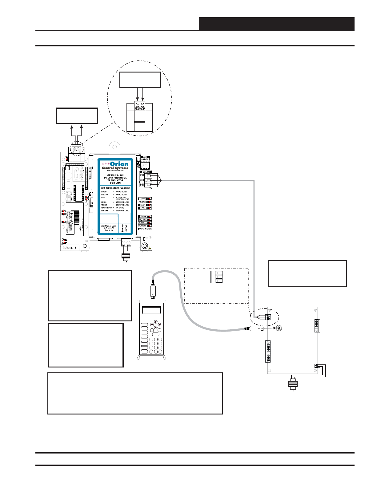
1. Familiarize yourself with the PT-Link II components (Figure 1).
2. Connect your PT-Link II to the Controller on your system (only
one) and connect your PT-Link II to the LON Network
(Figure 2).
3. Copy the contents of the PT Link CD to your PC’s Desktop.
You can also download the fi les from http://orioncontrols.com/
under PT-Link Setup Files.
4. Connect your PT-Link II to your computer using an
Ethernet connection (Figures 3 & 4 on page 6).
5. Change your PCs IP Address. Follow the directions that match
your current operating system - Windows NT, XP, Vista, 7 or 8.
See directions on pages 7 & 8.
6. Using RUINET, edit the Confi g.csv fi le and verify PT Link com-
munications. Follow the directions on pages 9-13.
7. If you run into any problems, follow the instructions in the
Troubleshooting section starting on page 14 of this guide.
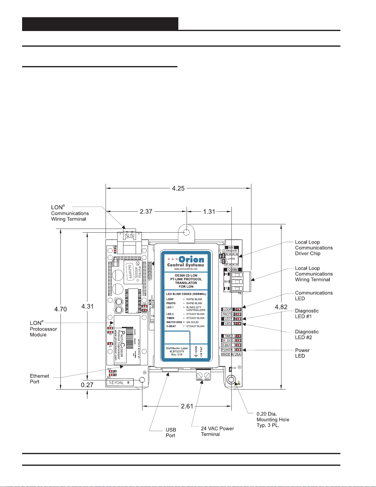
Figure 1: PT-Link II LON® Dimensions and Components
4
PT-Link II Interface
Page 5
®
LON Connection
®
To LON Network
®
LON Connection
®
To LON Network
PT-Link II LON® Technical Guide
Connection and Wiring Information
24 VAC
(10 VA)
Line Voltage
Caution: The LON Network
®
Communication Terminal Block
Must Be Disconnected Before
Connecting The Modular Service
Tool. After Programming The
Controller, Disconnect The Service
Typical Terminal Blocks. All
Wiring To Be T To T, SHLD
(G) To SHLD (G) & R To R
Tool and Then Reconnect The
Communication Terminal Block.
Note: All Programming Of
Controllers Must Be Done
Using The Modular Service
Tool. The Modular System
Manager Should Not Be Used
Mode
Selection
STATUS
SETPOINTS
SCHEDULES
OVERRIDES
ALARMS
CONFIGURATION
BALANCE - TEST
ON
UP
PREV
DOWN
CLEAR
ESC
ENTER
13
2
708
DEC
MINUS
-
NEXT
654
9
On A System That Has A PTLink Installed.
Modular Service Tool
Wiring Notes:
1.) All wiring to be in accordance with local and national electrical codes
and specifications.
2.) All communication wiring to be 18 gauge minimum, 2 conductor twisted
pair with shield. Use Belden #82760 or equivalent.
T
SHLD
R
Controller’s Address
Cannot Be Higher Than 16.
Controller
24 VAC
(8 VA)
Line Voltage
Figure 2: PT-Link II LON® Interface Wiring
PT-Link II Interface
Revised 8/31/11
5
Page 6
PT-Link II LON® Technical Guide
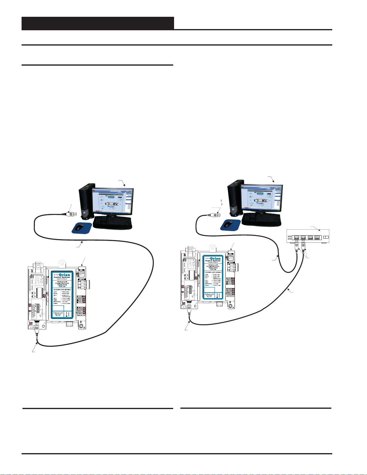
PT-Link LON
Connect Ethernet
Crossover Cable
To PT-Link Ethernet
Port
Ethernet Cable
Ethernet Hub
Connect Ethernet
Cable To Ethernet
Hub Port
Connect
Ethernet
Cables To
Ethernet Hub
Ports
1
2
3
4
Ethernet Cable
Computer
PT-Link II Ethernet Connection
PT-Link II Hardware Connection
You have two options for connecting the PT-Link II to your PC via
Ethernet:
1.) You may connect the PT-Link directly to your PC by using
a crossover cable (by others) as shown. See Figure 3 for
details.
2.) You can also connect both your PC and the PT-Link to an
Ethernet Hub with standard CAT5 cables. See Figure 4
for details.
Computer
Connect Ethernet
Crossover Cable Directly
To PC Ethernet Card Port
Locate a CA T5 cable and plug one end into your computer’s Ethernet
port (use a crossover cable if connecting directly to the PT-Link).
If connecting directly, plug the other end of the Cable into the Ethernet
port on the PT -Link. If connecting through an Ethernet Hub, plug the
other end of the PC cable into the hub, and use a second CAT5 cable
to connect the PT-Link to the hub as well.
Power up the PT-Link by plugging in the power cable. The PT-Link
may take up to three minutes to power up completely. Once the PTLink is powered up, you should notice that the green “GPI05” LED
light on the ProtoCessor Board remains on continuously. See Figur e
21 on page 15 for a diagram showing the location of the ProtoCessor
“GPI05” LED.
Ethernet Crossover Cable
PT-Link LON
Connect Ethernet
Crossover Cable
To PT-Link Ethernet
Port
Figure 3: Connecting With Crossover Cable
Figure 4: Connecting With Ethernet Cable & Hub
6
PT-Link II Interface
Page 7
Computer IP Address Set-up for
Windows XP, Vista, and 7
In order for the PT -Link II to communicate properly, it is imperative to
set the IP address of both the PT-Link II as well as the computer to be
within the same netmask. You need to change the IP address on your
computer. The following instructions will explain how to con fi gure the IP
address for Microsoft
Computer IP Address Set-up for Windows
NT & XP
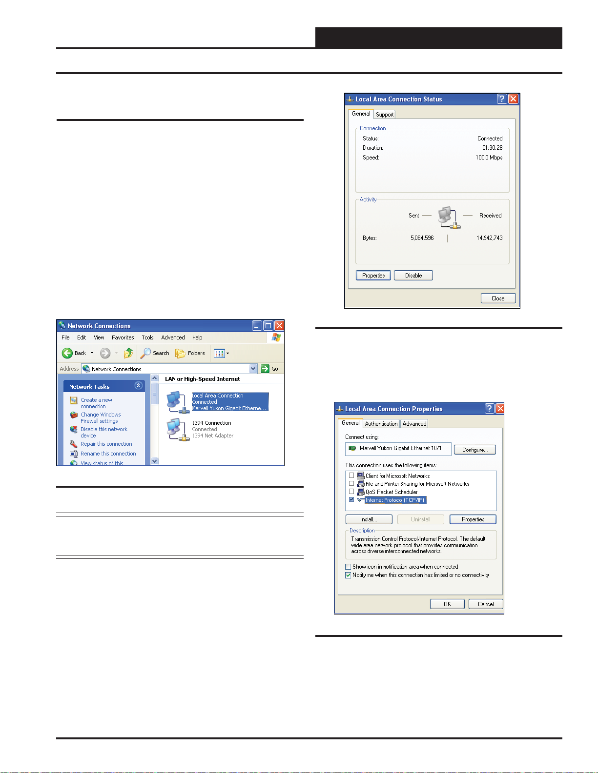
1.) Click <start>; then click <Control Panel>.
2.) Double-click on the Network Connections icon.
The Network Connections Window will appear (Figure 5).
®
Windows XP, Vista, and 7 operating systems.
PT-Link II LON® Technical Guide
IP Address Confi guration
Figure 6: Local Area Connection Status Window
Figure 5: Network Connections Window
NOTE: If any wireless connections are listed, disable them
by right-clicking the connection and selecting
<Disable>.
3.) In the Network Connections Window, double-click the
Local Area Connections entry. The Local Area Connection
Status Window will appear (Figure 6).
4.) As shown in Figure 6, click <Properties> in the lower
left of the window. The Local Area Connection Properties Win-
dow will appear.
Figure 7: Local Area Connection Properties Window
PT-Link II Interface
5). As shown in Figure 7, in the Connection Items list box,
be sure the Internet Protocol (TCP/IP) is checked. Select the
Internet Protocol (TCP/IP) item to highlight it and then click
<Properties>
appear.
. The Internet Protocol Properties Window will
7
Page 8
PT-Link II LON® Technical Guide
Confi guring the PT-Link Controller
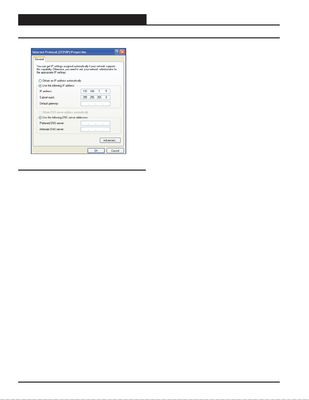
Figure 8: Internet Protocol Properties Window
6). Select the radio button in front of Use the following
IP address (Figure 8) and write down the current defaults
so that you can re-enter them when you fi nish confi guring
the PT-Link II and then type in the following
information:
a.) IP address 192.168.1.5
b.) Subnet mask 255.255.255.0
c.) Default Gateway is blank
7.) Click
windows are closed. You may have to reboot the computer
before the new values are valid.
<OK> until all of the above network confi guration
Computer IP Address Set-up for
Windows Vista, 7 & 8
1.) Click <start>; then click <Control Panel> (Vista &
Windows 7). Click
Click <All apps> and then click <Control Panel>
(Windows 8).
2.) Click on the Network and Internet icon.
3.) Click Network and Sharing Center.
4.)
From the shaded box in the left side of the window, select
Manage Network Connections (Vista) or Change adapter
settings (Windows 7).
5.) Right-click on the Local Area Connection icon and select
<Properties> for the drop down window.
6.) Choose Internet Protocol Version 4 (TCP/IPv4) by
highlighting it and then click
tocol Properties Window will appear (Figure 8).
7.) Select the radio button in front of Use the following
IP address (Figure 8) and write down the current defaults
so that you can re-enter them when you fi nish confi guring
the PT-Link II and then type in the following
information:
a.) IP address 192.168.1.5
b.) Subnet mask 255.255.255.0
c.) Default Gateway is blank
8.) Click
windows are closed. You may have to reboot the computer
before the new values are valid.
<OK> until all of the above network confi guration
<start>; then right-click for <All apps>.
<Properties>. The Internet Pro-
8
PT-Link II Interface
Page 9
PT-Link II LON® Technical Guide
Running RUINET
Connecting To The PT-Link II
1.) In order to communicate and program the PT-Link II you will
need to install RUINET software on your computer. If you do not
have the software, it is available for downloading at www.orioncontrols.com/software-new.html under PT-Link II Software
WARNING: Make sure to load RUINET onto your hard drive
and run the program from your hard drive. DO NOT under any
circumstances run RUINET from your cd drive.
2.) If RUINET is in the desktop directory (if it isn’t, locate its directory), double-click on RUINET, and the RUINET program should
run. Initially, you might see the screen below (Figure 9). Type <I> for
Specify IP Address and the message “Enter IP Address of the Field
Server to Connect to” will appear on the screen.
5.) On subsequent connections, a list of PT-Link II’s that have been
recently connected may appear under the message “Recently connected
to FieldServers.” Select the required PT-Link II by typing the Number
or Letter in the left hand column. (Figure 10).
Figure 10: RUINET PT-Link II Selection Menu
6.) Once connected, you will see the RUINET Main Menu (Figure
11). Unless you need to make changes to the confi g.csv fi le (see Steps
9-13 on page 10 & 11), you are now ready to send and receive fi les to
and from the PT-Link II .
Figure 9: RUINET PT-Link II Specify IP Address
3.) Type the IP Address of <192.168.1.24> and press <Enter>.
4.) If you have only one PT -Link II connected to the network, then RUINET will automatically connect to that particular PT -Link II ; otherwise,
a menu will appear to allow the selection of the desired PT-Link II .
NOTE: If RUINET is unable to establish a connection, there
are a few simple procedures you can perform to try to
determine the problem. To verify your network cables,
observe the green LED displayed directly above and to
the right of the Ethernet port. This LED should be on
if the 10 BaseT cable is good. Secondly, observe the
red LED displayed directly above and to the left of the
Ethernet port. This LED should be solid while RUINET
is running. If the LEDs are lit as expected, and RUINET
still does not receive replies, then the netmask is probably incorrect. If this does not help, then your Ethernet
setup on your PC is possibly not compatible. Ensure that
you have an Ethernet adapter installed in your software
confi guration and that it is confi gured to run the TCP/IP
protocol. If you are still unable to connect, please contact
WattMaster Controls.
NOTE: If you are installing a LON PT Link and the LON BAS
is using implicit addressing, no changes need to be made
to the confi g.csv fi le and you can skip to step 14.
Figure 11: RUINET PT-Link II Main Menu
PT-Link II Interface
9
Page 10
PT-Link II LON® Technical Guide
Changing the Confi g.csv File
NOTE: The PT-Link II contains an external interface fi le other-
wise called an XIF fi le (fserver.xif). The XIF fi le includes
information such as SNVT names and LON network
information. This fi le can be uploaded for use with LON
programming software. When uploaded, these fi les can be
located in the same directory that the RUINET executable
fi le is stored and run from. Be sure when uploading that
the correct fi le is specifi ed in the upload window. Refer
to Figures 12 & 13 below for screen details. Refer to
Appendix B, page 25 for details on uploading XIF fi les.
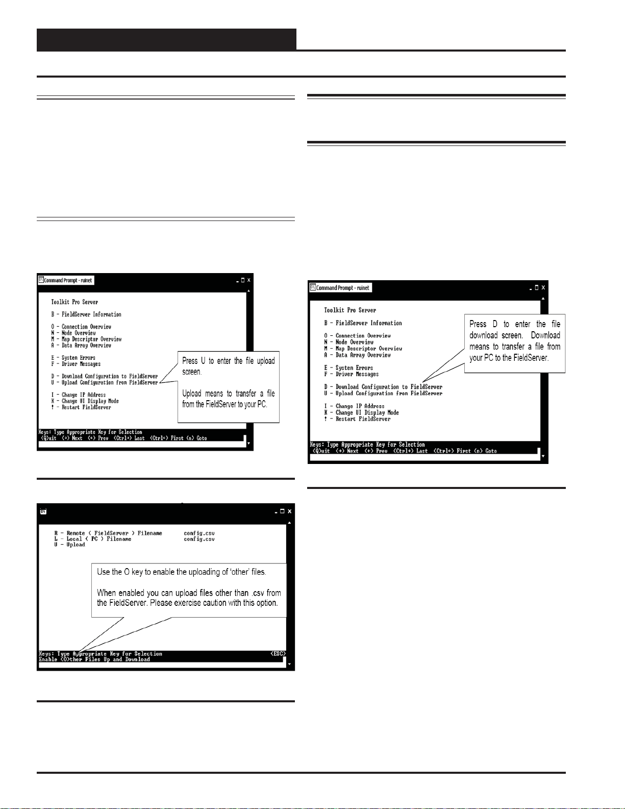
7.) Type the letter <U> to upload the Confi g fi le (Figure 12), then type
<U> again (Figure 13) for Upload.
WARNING: Only edit the confi g.csv fi le using Notepad. DO
NOT use Excel. Using Excel to edit the confi g.csv fi le will cor-
rupt its contents!
9.) Follow the directions under “Explicit and Implicit Addressing”
on pages 12 & 13 to make changes to the confi g.csv fi le.
10.) Once the changes are made to the confi g.csv fi le, click <File>
in the upper left and then click <Save>. Now close the fi le and
return to the RUINET Main Menu.
11.) From the RUINET Main Menu, type <D> to Download the new
confi g.csv fi le to the FieldServer (Figure 14).
Figure 12: RUINET PT-Link II Main Menu - Upload
Figure 13: RUINET PT-Link II Upload
8.) You will get confi rmation that the upload is complete. Type <N>
to open the confi g.csv fi le in Notepad.
Figure 14: Download new Confi g.csv fi le
10
PT-Link II Interface
Page 11
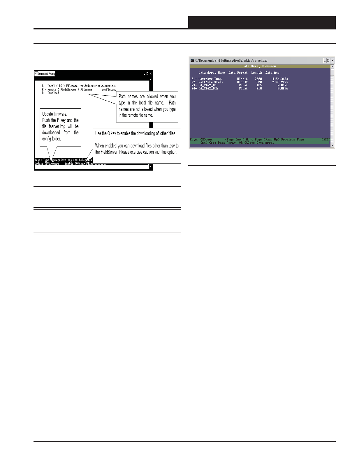
12.) At the next screen, (Figure 15), type <D> again.
PT-Link II LON® Technical Guide
Changing the Confi g.csv File
Figure 16: Data Array Overview Screen
Figure 15: Download new Confi g.csv fi le
NOTE: The utility will indicate when downloading is
complete. DO NOT reset the PT-Link II until this mes-
sage is displayed, as this will corrupt the PT-Link II .
NOTE: The Remote Filename option must always be named
“confi g.csv” for confi gurations; otherwise, it will be
ignored by the PT-Link II .
13.) Once the download is complete, restart the PT-Link II by
cycling power or press <Esc> to get back to the RUINET Main Menu
and then type
RUINET. It is possible to do multiple downloads to the PT-Link II
before resetting it. There will be a start-up period where you will be
unable to connect to the PT Link.
14.) From the RUINET Main Menu, type <A> for the Data Array
Overview. The Data Array Overview Screen will display (Figure 16).
<!> option to save the new confi guration fi le and restart
15.) This screen (Figure 16) will verify communication to the HVAC
units. Lines 1 & 2 should always be present. After a start-up period
of approximately 4 minutes, you will see 2 additional lines as shown.
This screen represents the PT Link communicating with 1 HVAC unit.
16.) Once these steps have been completed and you have verifi ed
that the reconfi gured PT Link has established communication to the
HVAC unit, it can now be added to the BAS network.
PT-Link II Interface
11
Page 12

PT-Link II LON® Technical Guide
Implicit Addressing
Explicit and Implicit Addressing
Clients can address the PT-Link using explicit or implicit addressing.
Clients using explicit addressing obtain their data transfer parameters
directly from the PT -Link II LON confi guration fi le (confi g.csv). Implicit
addressing is used when a Network Management T ool such as LonMaker®
is used to connect a PT-Link II LON to other LonWorks nodes—the
PT-Link II LON is assigned its data transfer (binding) parameters by
the Network Management Tool.
NOTE: The PT-Link II LON is confi gured from the factory to
use implicit addressing.
Implicit Addressing — Network Manager assigns addresses for
communication and ensures (via address tables in the devices) that
communication connections are known.
Explicit Addressing — Device knows the address of the point in
the remote device and communicates directly without the assistance of
the Network Manager.
Implicit Addressing Commissioning Using
LonMaker
1.) Ensure that the correct fi rmware and latest confi guration is
loaded on the PT-Link II LON.
NOTE: Each change in the PT -Link II LON requires re-commis-
sioning of the PT-Link II LON in LonMaker.
5.) Once Visio is open with the Network showing, drag a new
device onto the drawing from the toolbox.
6.) Follow the Device Network, making the following
selections:
Enter Device Name: Choose commission device
Specify Device Template: Choose upload from device
Specify Device Channel: Choose Auto Detect
Specify Device Properties: Leave as is (Ping is optional)
Identify Device: Choose service pin
Device Application Image: Leave unchecked
Initial State: Leave as is
7.) Press the service pin on the PT-Link II LON when asked to
do so, and the PT-Link II LON will be commissioned.
8.) Drag a new function block onto the drawing from the
toolbox. Give the function block a name and ensure that it
is allocated to the PT-Link II LON device.
9.) Once the function block is on the drawing, you can drag
input and output variables onto the function block. When
you do this, LonMaker will show you the variables
avail able for binding. Click on the variables you require
(or use the select “all” option), and they will be
commissioned onto the function block.
10.) You are now ready to connect these variables to other
devices by dragging connections from the toolbox and
connecting the variables.
2.) Ensure that the PT-Link II LON and the LonMaker machine
are on the same network.
3.) Open the existing Network in LonMaker or create a new
Network.
4.) Click on <Create New Network> and follow the network
wizard, making the following selections:
Network Interface: Choose Network Attached
Management Mode: Choose Onnet unless you are
working offl ine
Registered Plug-ins required: None
12
PT-Link II Interface
Page 13
Explicit Addressing & Domain Table Setup
To use explicit addressing, the client needs to change the factory settings
contained in the PT-Link II LON’s confi guration fi le (confi g.csv). The
following are the steps to change the confi guration fi le from implicit to
explicit addressing:
1.) Upload and open the confi g.csv fi le.
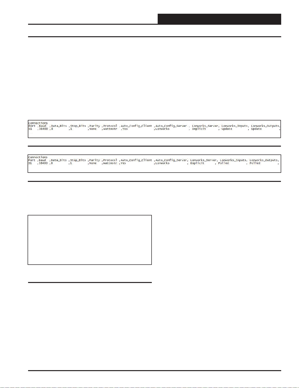
2.) Locate the “Connections” section.
3.) Locate the “Lonworks_Server” column and change the
value from “Implicit” shown in Figure 17 to “Explicit”
shown in Figure 18. You should also change the “Lon
works _Input” and “Lonworks_Outputs” from Update to
Polled.
Figure 17: PT-Link II LON Implicit Confi guration
PT-Link II LON® Technical Guide
Explicit Addressing
Figure 18: PT-Link II LON Explicit Confi guration
In addition, the PT -Link II LON must have its domain, subnet, and node
IDs set. This feature is enabled in the confi guration fi le by fi lling out
the Title and System_Address fi elds of the PT-Link II LON parameters
as follows:
//==================================================
//
// Common Information
//
Bridge
System_Address ,Title
23 ,”:D48:S01:Wattmaster Explicit Lon v1.00d”
Figure 19: PT-Link II LON Domain and Subnet
Setting
The Title fi eld must start with “:D”, followed by the domain_id in
hexadecimal notation, followed by “:S”, followed by the subnet_id in
hexadecimal notation, and enclosed by “:”. The domain length is automatically determined by the number of digits in the [domain_id] fi eld.
With 2 hexadecimal digits constituting 1 byte, “:D123456:”, for example,
would have a length of 3.
Once the domain table has been set, the “:Dxx:Sxx:” part of the Title
fi eld will be removed.
Now the Title fi eld will be left with [Title continued…] which may be
the Node self documentation string or any title.
PT-Link II Interface
13
Page 14
PT-Link II LON® Technical Guide
Troubleshooting the PT-Link Controller
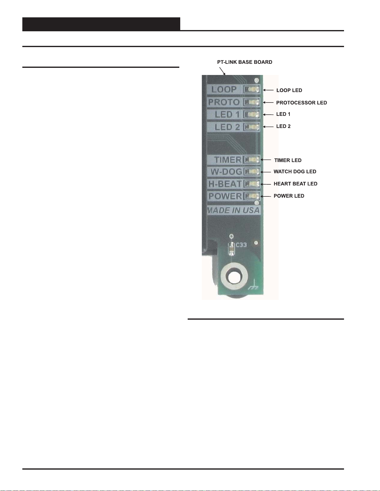
PT-Link II Board LEDs
The PT-Link II LON® is equipped with LEDs that can be used for
troubleshooting. There are eight LEDs on the PT-Link II board. See
Figure 20 for the locations of the LEDs on the PT-Link II board. The
LED descriptions and functions are listed in the following paragraphs.
POWER LED
When the PT -Link II LON® is powered up, the “POWER” LED should
light up and stay on continuously. If it does not light up, check to be sure
that you have 24 VAC connected to the board, that the wiring connections are tight, and that they are wired for correct polarity. The 24 VAC
power must be connected so that all ground wires remain common. If
after making all these checks the “POWER” LED still does not light
up, please contact WattMaster Controls Technical Support at our Toll
Free number—866-918-1100—for assistance.
LOOP LED
When power is applied to the PT -Link II LON
also light up. The LED should fl icker rapidly, indicating that the PT -Link
II is trying to communicate with the controllers on the loop. A “fl icker”
is defi ned as a brief moment when the LED turns off and back on. If the
“LOOP” LED does not operate as indicated above, fi rst power down
the unit and then reapply power. If this does not work, please contact
W attMaster Controls Technical Support at our Toll Free number—866918-1100—for assistance.
®,
the “LOOP” LED will
LED 1
When power is fi rst applied, “LED 1” will be off temporarily and then
will blink one time for each controller it is communicating with. For
example, if you have 4 controllers on the loop connected to the PT -Link
II , “LED 1” will blink 4 times. If the amount of blinks does not match
the number of controllers connected to the loop, it indicates there is a
communications problem. The best way to fi nd out which board is not
communicating is to go to each controller and look at its “COMM”
LED. The “COMM” LED should be solid and will fl icker occasionally
indicating communication with the PT -Link II LON
LED does not fl icker, there is no communication with that controller.
®
. If the “COMM”
LED 2
When power is fi rst applied, “LED 2” will be off temporarily and then
will blink slowly indicating that the PT-Link II baseboard is communicating with the ProtoCessor Module. If “LED 2” does not blink,
check that the ProtoCessor Module is installed correctly on the PT -Link
II baseboard and that the “PWR” LED is lit up on the ProtoCessor
Module.
PROTO LED
When the PT-Link II is fi rst powered up, the “PROTO” LED should
light up and blink continuously. This LED verifi es communication with
the board and the ProtoCessor. If the LED doesn’t light up, check that the
ProtoCessor is installed correctly and fi rmly connected to the Base Board.
The “PWR” LED should also be lit on the ProtoCessor Module.
Figure 20: PT-Link II LON® LED Locations
WATCH DOG LED
The “W-DOG” LED is used for troubleshooting by W attMaster Controls
Technical Support. The “W-DOG” LED should always be on solid.
HEARTBEAT LED
The “H-BEAT” LED blinks to show the PT-Link II board software is
running. If the LED doesn’t light up, and all other checks have been
made, please contact W attMaster Controls T echnical Support at our T oll
Free number—866-918-1100—for assistance.
TIMER LED
The “TIMER” LED is used for troubleshooting by W attMaster Controls
Technical Support. The “TIMER” LED should always be blinking
steadily.
14
Revised 1/14/10
PT-Link II Interface
Page 15

Troubleshooting the PT-Link Controller
ProtoCessor Module LEDs
PWR LED
When the PT -Link II is fi rst powered up, the “PWR” LED should light
up and stay on continuously. See Figur e 21. If the LED doesn’t light up,
check that the ProtoCessor is installed correctly and fi rmly connected
to the Base Board.
GPI05 LED
The “GPI05” LED will light up when the Base Board and the ProtoCessor Module have established communications. See Figure 21. This can
take up to 3 minutes depending on the number of units connected to
the PT-Link II . If it fails to light up after 3 minutes, check that the
ProtoCessor is installed correctly and fi rmly to the Base Board.
LON LED
Once the unit is powered up, the “LON” LED will blink continuously
until the PT-Link II has been commissioned. Once commissioned, the
“LON” LED will remain off.
PT-Link II LON® Technical Guide
LA LED
Once the unit is powered up, the “LA” LED must be blinking constantly.
See Figure 21. If this LED is constantly on or off, the Module is not
working properly and needs to be replaced.
TX & RX LEDs
The “TX” and “RX” LEDs work together to indicate that communication
is being established with the desired protocol network. If both LEDs
are blinking, then communication is working properly. See Figure
21. If not, check the protocol network wiring and the baud rate in the
confi guration fi le.
D14 & D15 LEDs
The “D14” and “D15” LEDs work together to indicate that communication is being transmitted and received from the USB Port when
performing an update to the PT-Link II software.
If all of these tests are made and the controller still doesn’t operate,
please contact WattMaster Controls Technical Support at our Toll Free
number—866-918-1100—for assistance.
Figure 21: PT-Link II LON® LED Locations
PT-Link II Interface
Revised 1/5/11
15
Page 16
PT-Link II LON® Technical Guide
Using RUINET
Using RUINET
Before continuing with the troubleshooting, make sure the PT-Link II
is connected correctly and the RUINET software is installed, running,
and functioning correctly.
Verifying Proper Communications
From the RUINET Main Screen, press <O> to go the Connection
Overview Screen. This screen supplies information on communication
between the PT -Link II and remote devices. A number of aspect screens
are available, and some of the aspect screens have more than one page.
Use the space bar to toggle between aspects and use the <PgUp> and
<PgDn> keys to toggle between pages of the same aspect. The Connec-
tion Overview and Settings Aspect Screen is shown in Figure 22.
The main purpose in this screen is to verify that messages and characters
are being transmitted and received. In addition, it shows the number
of communication errors. If the PT-Link II connection “03” is the
protocol connection, verify that is communicating appropriately. If it
is not, check that the PT-Link II LEDs are working properly, the unit
is wired correctly, and the PT-Link II is confi gured correctly. If the
number of errors is constantly increasing, move to the Error Scr een by
pressing the
Use the <PgUp> and <PgDn> keys to toggle between pages of the
Error Screen.
<Space Bar> 3 times to fi nd out the cause of the errors.
Figure 22: Connection Overview Screen
Verifying Proper Values
To verify that the correct values for each unit are being communicated
to the PT-Link II , move to the Data Array Overview Screen. To get to
the screen, press
for screen details.
In the Data Array Overview Screen (Figure 23) you will be able to see
the data arrays of all the units connected to the PT-Link II denoted by
an array name “DA_XXX_IY”—Y being the address of the unit minus
one. The Address of the unit is determined by a set of dip switches.
To view the values being communicated from a specifi c unit, move to
the Data Array Detail Screen (Figure 24) of the unit by entering the
number under which it is listed. For example, for the unit listed in the
third position, enter
To understand what each value means, look at the Data Array Tables
for the desired unit type, VCM-X, SA, or VCM. You can change the
writable values from this screen by using the modify command. T o use
the modify command, press
and then enter the Offset you want to change followed by a space and
the new value.
Example: T o change the Cooling Supply Setpoint to 60 in the VCM, press
<M>, enter <58 60>, and then press <Enter>. This could be useful to
prove that the unit can take and keep the setpoints properly.
<A> from the RUINET Main Menu. See Figure 23
<03>.
<M> from the Data Array Detail Screen
Figure 23: Data Array Overview Screen
16
Figure 24: Data Array Detail Screen
PT-Link II Interface
Page 17
PT-Link II LON® Technical Guide
Updating the PT-Link II Controller
Programming the PT-Link II with
BootLoader
The PT-Link II is equipped with the ability to update its software with
the use of a computer. You will need the following before you begin:
• PT-Link II in need of an update (powered up,
no other connections necessary)
• Computer running Microsoft Windows
system
TM
operating
• Prism II software from www.orioncontrols.com/software-
new.html
• Latest version of PT-Link II software (e-mailed from our
tech support staff or downloaded from any of our websites)
and software sheet
• USB Driver Setup.exe fi le located on PT-Link II CD or
downloaded from any of our websites
• USB cable
Follow these simple steps to update the PT-Link II:
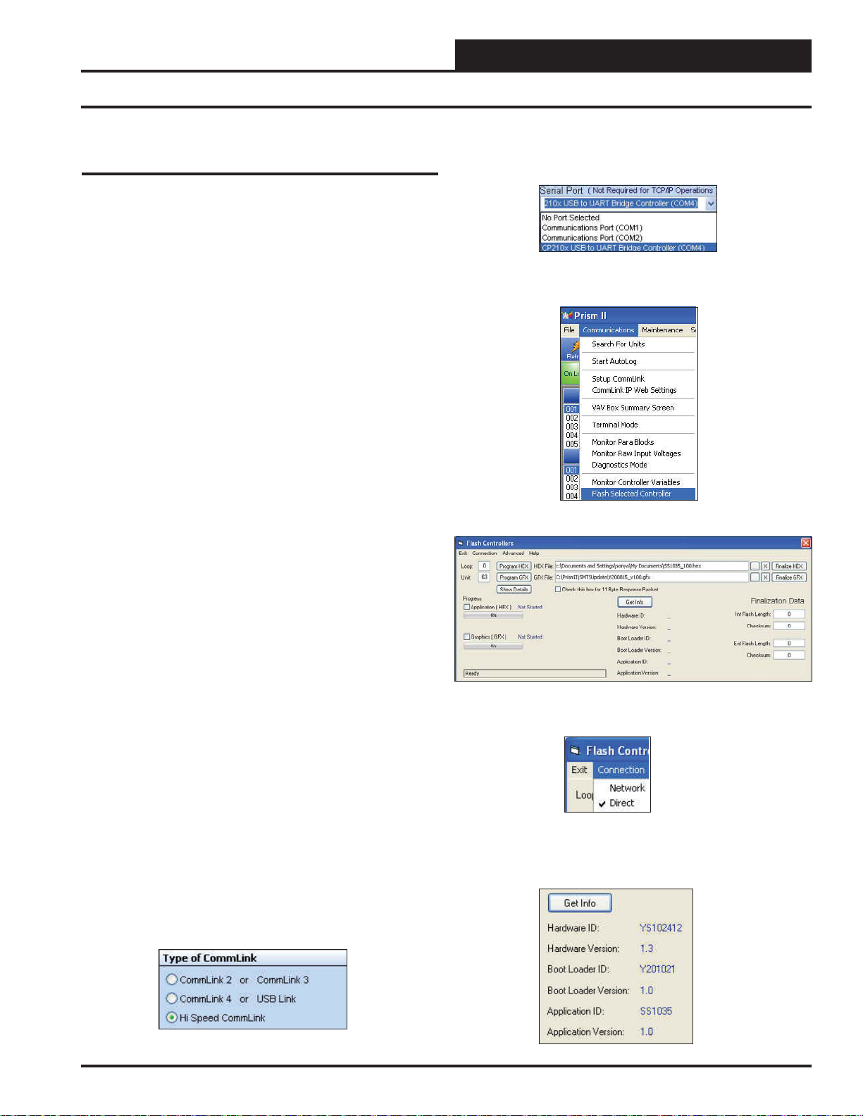
1.) Turn on your computer and download the latest Prism II software
from www.orioncontrols.com/software-new.html.
8.) In the Job-Sites Window, from the Serial Port drop down list, select
the correct COM port. If you don’t know the COM port number or if the
number is 10 or higher, follow the directions on pages 19-20.
9.) From Prism II’s Communications tab, select “Flash Selected
Controller.”
10.) The Flash Controller Window will appear.
2.) Either download the PT -Link II update fi le from http://techsupport.
wattmaster.com or save the fi le to your computer from the e-mail you
received from Tech Support. Record the path and name of the fi le for
later use. Also, print the software sheet provided for future reference.
3.) Run the USB Driver Setup.exe fi le (found on the PT-Link II CD or
downloaded from any of our websites) so that Prism can communicate
to the PT Link II. Unzip the fi le to the directory where you saved your
PT-Link II software.
4.) Plug the USB cable into the computer’s and PT-Link II’s USB
ports.
5.) A message will pop-up from the lower menu bar of Windows that
reads, “Found New Hardware.” Click on this message and follow the
instructions that appear to install the USB drivers.
6.) Open Prism 2 and Login with the User Name, admin and the Password, admin. If successful, “Administrator Access” will appear at the
lower right of the Prism program.
prior to 4.0, the Login is fl ash. If successful, “Level 4 Access” will ap-
pear at the lower right of the Prism program.
7.) Click on the <Job-Site> icon. The Job-Sites Window will appear.
In the Type of CommLink Dialog Box, select “Hi Speed CommLink.”
NOTE: If using a Prism 2 version
11.) From the Flash Controller Window’s Connection tab, select
“Direct”. Keep the Flash Controller Window open.
12.) Cycle power to the PT-Link II and within 5 seconds, click the
<Get Info> button in the Flash Controller W indow. The PT-Link II in-
formation will now appear in the window under the
<Get Info> button.
PT-Link II Interface
Revised 7/28/14
17
Page 18

PT-Link II LON® Technical Guide
Updating the PT-Link II Controller
13.) The Application ID should be SS1035 and the Application V ersion
should match the software version you will be updating to.
14.) In the HEX File fi eld, enter the path and name of the HEX fi le you
downloaded and/or copied to your hard drive. Use the Browse button
(...) to the right of the fi eld if you need help in locating the fi le.
15.) Now, cycle power to the PT-Link II once again and within 5
seconds click on the
cessful, you should see the Progress Application HEX bar showing the
progress percentage.
<Program HEX> button (shown above). If suc-
16.) When the bar shows 100% completed, verify the PT-Link II’s
software is running by observing the Timer LED blinking.
17.) Verify the PT-Link II’ s Application V ersion by once again cycling
power to the PT-Link II and within 5 seconds clicking the
button.
18.) Verify all fi elds are correct in the information below the
button and under “Finalization Data.” The “Int Flash Length”
Info>
and “Checksum” values should match the values provided with the
software sheet.
<Get Info>
<Get
18
Revised 1/14/10
PT-Link II Interface
Page 19

PT-Link II LON® Technical Guide
Updating the PT-Link II Controller
Finding What COM Port Number the
PT-Link II is Using
1. Left-click on <Start>, located on the bottom
left of the Windows Tool Bar.
2. Select
3. Double-click the System Icon.
<Control Panel>.
6. Click on the plus sign next to Ports to see all of the
common ports.
7. Locate the USB Serial Port (COM#). The COM# in
parentheses is the port it is located on. Write this COM
port number down. You will need to know this when
setting up the Prism software.
8. If the COM port number is 10 or greater, go to
“Changing the USB COM Port Number” on page 20.
4. Click the
<Hardware> tab.
5. Click the
<Device Manager> button.
PT-Link II Interface
Revised 10/11/12
19
Page 20

PT-Link II LON® Technical Guide
Updating the PT-Link II Controller
Changing the USB COM Port Number
When the CommLink is fi rst plugged in, it will be assigned a COM port
number to be used for communicating with the Prism software. If the
port number is 10 or greater, it needs to be changed to a value less than
10 to be recognized by Prism.
1. Click <Start>, click <Control Panel>, click
<System>, click the <Hardware> tab, and then
click <Device Manager> to get to the Device
Manager Window.
2. Click on the plus sign next to Ports to see all of the
COM ports.
3. Right-click on “USB Serial Port (COM#)” and select
<Properties>. In the Properties Window, select the
<Port Settings> tab.
4. To assign a port number less than 10, click on
<Advanced>. The Advanced Settings Window
will appear.
5. In the COM Port Number drop box, select which
COM port you wish to use. Make sure you select a
COM port number that is not currently in use (you can
see the ports in use in the Device Manager Window).
Select a port that is less than 10.
NOTE: Windows
has ever been installed on your computer. So if there are
no available ports below 10, choose a port number less
than 10 for a device listed that you know you are not
currently using.
6. Once you select the correct COM port number, click
<OK> and close any windows opened in the process
of changing the port number. Make note of this number
because you will need it for your Prism setup.
®
will assign a port number to every device that
20
Revised 1/14/11
PT-Link II Interface
Page 21

PT-Link II LON® Technical Guide
VCB-X Data Array
VCB-X Modular Data Array For Field Server
Offset 0 1 2 3 4567
0
8
16
24
32
40
48
56
64
72
80
88
96
104
112
120
128
136
144
152
160
168
AppVer ClSt HtSt SpcTp SaTp OaTp UnitMode CtrlSts
ClEnbl HtEnbl EcoEnbl FanDly OnRlys EcoPos VfdBwPos AlmSts
AlmGrp1 AlmGrp2 AlmGrp3 SaTpAlm OaTpAlm SpcTpAlm MchClAlm MchHtAlm
PofAlm DrtFlAlm SmokeAlm LoSaAlm HiSaAlm CtrlTpCF CtrlTpHF CtrlTp
InRh InRhStM MdClPos MdHtPos OcpClSt OcpHtSt UnClOst UnHtOst
SaClSt SaHtSt SpcTpOst SaTpOst OaTpOst SchdFrc OnRly1 OnRly2
OnRly3 OnRly4 OnRly5 OnRly6 MnExRly1 MnExRly2 MnExRly3 MnExRly4
MnExRly5 RlExRly1 RlExRly2 RlExRly3 RlExRly4 RlExRly5 RlExRly6 RlExRly7
RlExRly8 RlExRly9 RlExRly10 RlExRly11 RlExRly12 MinEcoSt OaCFM EtCFM
SaCFM FrcHvacM FrcFanSp FrcEcono SaTpStM RaTp OaRh StaticPr
CO2 BuildPr EtFnSpd CoilTp RaCFM HeadPr RtVlvPos LvWtrTp
MdGsVPos HeadPrSt CdCtrSg1 OaClSt OaHtSt WmupTg RhDewpSt EcoEnbSt
RaTpOst ColTpOft LWAmbnt PreHtAmb C02MinLv C02MaxLv InRhSt StatPrSt
RfPrSt OACfmMin HiInRh ClHdPrSt HtHdPrSt LoClTpSt HiClTpSt SaClRt
SaHtRt ClLoRt ClHiRt HtLoRt HtHiRt CtrlMod DschgTp OaWtbl
OaDewPt SucPr CoilTpSt RetBydmp RaDmp RaRH SldAdOfs MdSelDb
ClStgWdw HtStgWdw MchClLkt MchHtLkt LoSaCf HiSaCf DfrSt LvH2OOst
CO2Ost CTpHiAlm CTpLoAlm HpLkt VFDClMin VFDHtMin VFDVtMin MaxEcoHt
MaxEcoCO HpDfrInt AptDfr DuctPfDb RlfPrDb OaCfmDb SZVAVFnI SaWmupSt
SaCldnSt RehtEnbl EmHtEnbl RaTpAlm MisEM1 ColPfAlm CO2Alm DschgAlm
OaCfmAlm ExtCmSr SaCfmSr RaCfmSr MisMHGRV MisMDGAS Mis12Rly HiCtrlMd
LoCtrlMd DigCmpCf DigCmpLk HiHedPr H2OProf LoSucPr HiSucPr –
Table 2: VCB-X Modular Data Array For Field Server
PT-Link II Interface
Revised 7/8/14
21
Page 22

PT-Link II LON® Technical Guide
VCM-X Modular Data Array
VCM-X Modular Data Array For Field Server
Offset 0 1 2 34567
0
8
16
24
32
40
48
56
64
72
80
88
96
104
112
120
128
AppVer ClSt HtSt OaWtbl TpDmnd SpcTp SaTp RaTp
OaTp DuctPr OaRh UnitMode CtrlSts ClEnbl HtEnbl EcoEnbl
FanDly PofCfg CO2Cfg MdHt2Ins Rt2Ins OnRlys ExRlys12 ExRlys34
EcoPos VfdBwPos VfdExPos AlmSts AlmGrp1 AlmGrp2 AlmGrp3 SaTpAlm
OaTpAlm SpcTpAlm MchClAlm MchHtAlm PofAlm DrtFAlm SmokeAlm LoSaAlm
HiSaAlm CtrlTpCF CtrlTpHF CtrlTp InRh InRhStM DptStM MdClPos
MdHtPos MdHt2Pos Rt2Pos OcpClSt OcpHtSt UnClOst UnHtOst WtblSt
SaClSt SaHtSt WmupSt SpcTpOst SaTpOst RaTpOst OaTpOst CoilTpSt
DptSt InRhSt DuctPrSt RfPrSt SchdFrc OnRly1 OnRly2 OnRly3
OnRly4 OnRly5 ExRly1 ExRly2 ExRly3 ExRly4 ExRly5 ExRly6
ExRly7 ExRly8 ExRly9 ExRly10 ExRly11 ExRly12 ExRly13 ExRly14
ExRly15 ExRly16 CO2St MinEcoSt CO2Level ByPasDmp RaDmp RfPr
OaDwpt CoilTp SaTpStM PreHtSp OaCFM EtCFM SaCFM OACfmSt
OACfmRs OACfmStM MdCmp2 HdPr1 HdPr2 CdFan1 CdFan2 RmVFDPos
SaClRt SaHtRt ClLoRt ClHiRt HtLoRt HtHiRt T24EcFb T24TpAlm
T24NEWS T24EWISN T24DpAlm T24ExsOA RaTpAlm AlmGrp5 HdPr22 HdPr22
CdFan21 CdFan22 ––––––
Table 3: VCM-X Modular Data Array For Field Server
22
Revised 8/19/14
PT-Link II Interface
Page 23

PT-Link II LON® Technical Guide
VCM-X WSHP Tulsa Data Array
VCM-X WSHP (Tulsa) & RNE Data Array For Field Server
Offset 0 1 2 34567
0
8
16
24
32
40
48
56
64
72
80
88
96
104
112
120
128
136
144
AppVer ClSt HtSt OaWtbl TpDmnd SpcTp SaTp RaTp
OaTp DuctPr OaRh UnitMode CtrlSts ClEnbl HtEnbl EcoEnbl
FanDly PofCfg CO2Cfg MdHt2Ins Rt2Ins OnRlys ExRlys12 ExRlys34
EcoPos VfdBwPos VfdExPos AlmSts AlmGrp1 AlmGrp2 AlmGrp3 SaTpAlm
OaTpAlm SpcTpAlm MchClAlm MchHtAlm PofAlm DrtFAlm SmokeAlm LoSaAlm
HiSaAlm CtrlTpCF CtrlTpHF CtrlTp InRh InRhStM DptStM MdClPos
MdHtPos MdHt2Pos Rt2Pos OcpClSt OcpHtSt UnClOst UnHtOst WtblSt
SaClSt SaHtSt WmupSt SpcTpOst SaTpOst RaTpOst OaTpOst CoilTpSt
DptSt InRhSt DuctPrSt RfPrSt SchdFrc OnRly1 OnRly2 OnRly3
OnRly4 OnRly5 ExRly1 ExRly2 ExRly3 ExRly4 ExRly5 ExRly6
ExRly7 ExRly8 ExRly9 ExRly10 ExRly11 ExRly12 ExRly13 ExRly14
ExRly15 ExRly16 CO2St MinEcoSt CO2Level ByPasDmp RaDmp RfPr
OaDwpt CoilTp SaTpStM PreHtSp OaCFM EtCFM SaCFM OACfmSt
OACfmRs OACfmStM MdCmp2 HdPr1 HdPr2 CdFan1 CdFan2 WaterTpA
WaterTpB A1LSPAlm A1LktAlm A2LSPAlm A2LktAlm B1LSPAlm B1LktAlm B2LSPAlm
B2LktAlm LWT1Alm LWT2Alm POWF1Alm POWF2Alm ComMAlm RmVFDPos SaClRt
SaHtRt ClLoRt ClHiRt HtLoRt HtHiRt T24EcFb T24TpAlm T24NEWS
T24EWISN T24DpAlm T24ExsOA RaTpAlm AlmGrp5 HdPr22 HdPr22 CdFan21
CdFan22 –––––––
Table 4: VCM-X WSHP (Tulsa) & RNE Data Array For Field Server
PT-Link II Interface
Revised 8/19/14
23
Page 24

PT-Link II LON® Technical Guide
VCM-X WSHP (Coil) & VCM-X Data Arrays
VCM-X WSHP (Coil) Data Array For Field Server
Offset 0 1 2 34567
0
8
16
24
32
40
48
56
64
72
80
88
96
104
112
120
128
AppVer ClSt HtSt OaWtbl TpDmnd SpcTp SaTp RaTp
OaTp DuctPr OaRh UnitMode CtrlSts ClEnbl HtEnbl EcoEnbl
FanDly PofCfg CO2Cfg MdHt2Ins Rt2Ins OnRlys ExRlys12 ExRlys34
EcoPos VfdBwPos VfdExPos AlmSts AlmGrp1 AlmGrp2 AlmGrp3 SaTpAlm
OaTpAlm SpcTpAlm MchClAlm MchHtAlm PofAlm DrtFAlm SmokeAlm LoSaAlm
HiSaAlm CtrlTpCF CtrlTpHF CtrlTp InRh InRhStM DptStM MdClPos
MdHtPos MdHt2Pos Rt2Pos OcpClSt OcpHtSt UnClOst UnHtOst WtblSt
SaClSt SaHtSt WmupSt SpcTpOst SaTpOst RaTpOst OaTpOst CoilTpSt
DptSt InRhSt DuctPrSt RfPrSt SchdFrc OnRly1 OnRly2 OnRly3
OnRly4 OnRly5 ExRly1 ExRly2 ExRly3 ExRly4 ExRly5 ExRly6
ExRly7 ExRly8 ExRly9 ExRly10 ExRly11 ExRly12 ExRly13 ExRly14
ExRly15 ExRly16 CO2St MinEcoSt CO2Level ByPasDmp RaDmp RfPr
OaDwpt CoilTp SaTpStM PreHtSp OaCFM EtCFM SaCFM OACfmSt
OACfmRs OACfmStM MdCmp2 HdPr1 HdPr2 CdFan1 CdFan2 WaterTpA
A1LSPAlm A1LktAlm B1LSPAlm B1LktAlm LWT1Alm POWF1Alm ComMAlm RmVFDPos
SaClRt SaHtRt ClLoRt ClHiRt HtLoRt HtHiRt T24EcFb T24TpAlm
T24NEWS T24EWISN T24DpAlm T24ExsOA RaTpAlm – – –
Table 5: VCM-X WSHP (Coil) Data Array For Field Server
VCM-X Data Array For Field Server
Offset 01234567
0
8
16
24
32
40
48
56
64
72
80
88
96
104
AppVer ClSt HtSt OaWtbl TpDmnd SpcTp SaTp RaTp
OaTp DuctPr OaRh UnitMode CtrlSts ClEnbl HtEnbl EcoEnbl
FanDly PofCfg CO2Cfg MdHt2Ins Rt2Ins OnRlys ExRlys12 ExRlys34
EcoPos VfdBwPos VfdExPos AlmSts AlmGrp1 AlmGrp2 AlmGrp3 SaTpAlm
OaTpAlm SpcTpAlm MchClAlm MchHtAlm PofAlm DrtFAlm SmokeAlm LoSaAlm
HiSaAlm CtrlTpCF CtrlTpHF CtrlTp InRh InRhStM DptStM MdClPos
MdHtPos MdHt2Pos Rt2Pos OcpClSt OcpHtSt UnClOst UnHtOst WtblSt
SaClSt SaHtSt WmupSt SpcTpOst SaTpOst RaTpOst OaTpOst CoilTpSt
DptSt InRhSt DuctPrSt RfPrSt SchdFrc OnRly1 OnRly2 OnRly3
OnRly4 OnRly5 ExRly1 ExRly2 ExRly3 ExRly4 ExRly5 ExRly6
ExRly7 ExRly8 ExRly9 ExRly10 ExRly11 ExRly12 ExRly13 ExRly14
ExRly15 ExRly16 CO2St MinEcoSt CO2Level ByPasDmp RaDmp RfPr
OaDwpt CoilTp SaTpStM PreHtSp OaCFM EtCFM SaCFM OACfmSt
OACfmRs OACfmStM SaClRt SaHtRt ClLoRt ClHiRt HtLoRt HtHiRt
Table 6: VCM-X Data Array For Field Server
24
Revised 4/4/13
PT-Link II Interface
Page 25

PT-Link II LON® Technical Guide
SA & VCM Data Arrays
SA Controller Data Array For Field Server
Offset 01234567
0
8
16
24
32
40
48
56
64
72
80
88
96
AppVer ClSt HtSt TpDmnd SpcTp SaTp DuctPr UnitMode
CtrlSts ClEnbl HtEnbl EcoEnbl FanDly MdHt2Ins Rt2Ins EcoPos
VfdBwPos SaTpAlm SpcTpAlm MchClAlm MchHtAlm PofAlm DrtFAlm LoSaAlm
HiSaAlm CtrlTpCF CtrlTpHF CtrlTp InRh InRhStM DptStM MdClPos
MdHtPos MdHt2Pos Rt2Pos OcpClSt OcpHtSt UnClOst UnHtOst SaClSt
SaHtSt WmupSt SpcTpOst SaTpOst CoilTpSt DptSt InRhSt DuctPrSt
SchdFrc OnRly1 OnRly2 OnRly3 OnRly4 OnRly5 ExRly1 ExRly2
ExRly3 ExRly4 ExRly5 ExRly6 ExRly7 ExRly8 ExRly9 ExRly10
ExRly11 ExRly12 ExRly13 ExRly14 ExRly15 ExRly16 CoilTp SaTpStM
PreHtSp EaTp EwTp EaRH HdPr1 HdPr2 CoilTp2 EaDpt
WSEByp WSEByp2 MdCmp2 CoilTpSt CdPos1 CdPos2 EaTpAlm EmerAlm
PoWFAlm DrnAlm EaTpOst EwTpOst SaClRt SaHtRt ClLoRt ClHiRt
HtLoRt HtHiRt ––––––
Table 7: SA Controller Data Array For Field Server
VCM Data Array For Field Server
Offset 01234567
0
8
16
24
32
40
48
56
64
72
80
88
96
AppVer ClSt HtSt OaWtbl TpDmnd SpcTp SaTp RaTp
OaTp DuctPr OaRh UnitMode CtrlSts ClDmnd HtDmnd DehmDmnd
ClEnbl HtEnbl EcoEnbl FanDly WmupDmnd PofCfg CO2Cfg MdHt2Ins
Rt2Ins OnRlys ExRlys12 ExRlys34 EcoPos VfdBwPos VfdExPos AlmSts
AlmGrp1 AlmGrp2 AlmGrp3 SaTpAlm OaTpAlm SpcTpAlm MchClAlm MchHtAlm
PofAlm DrtFlAlm SmokeAlm LoSaAlm HiSaAlm CtrlTpCF CtrlTpHF CtrlTp
InRh InRhStM DptStM MdClPos MdHtPos MdHt2Pos Rt2Pos OcpClSt
OcpHtSt UnClOst UnHtOst WtblSt SaClSt SaHtSt WmupSt SpcTpOst
SaTpOst RaTpOst OaTpOst CoilTpSt DptSt InRhSt DuctPrSt RfPrSt
SchdFrc OnRly1 OnRly2 OnRly3 OnRly4 OnRly5 ExRly1 ExRly2
ExRly3 ExRly4 ExRly5 ExRly6 ExRly7 ExRly8 ExRly9 ExRly10
ExRly11 ExRly12 ExRly13 ExRly14 ExRly15 ExRly16 CO2St MinEcoSt
CO2Level ByPasDmp RaDmp RfPr OaDwpt CoilTp SaTpStM PreHtSp
Table 8: VCM Data Array For Field Server
PT-Link II Interface
25
Page 26

PT-Link II LON® Technical Guide
Appendix A & B
Brown/White
White/Brown
Orange/White
White/Blue
Blue/White
White/Orange
RJ-45 Connector as viewed
from the bottom side
8
7
6
5
4
3
RJ-45 Connector as viewed
from the bottom side
White/Orange
1
Orange/White
2
White/Green
3
Blue/White
4
White/Blue
5
Green/White
6
Use the standard EIA/TIA color code for "CROSS OVER CABLE" as shown.
It is the same as a standard Cat 5 patch cabling. The outer cable jacket should
not
Be "Orange" in color. This is a straight thru pin 1 to pin 1 cable.
not
Figure 25: RJ-45 8P8C Cable for WattMaster Cross Over Networking - WattMaster Part #HZ000136
External Interface Files (XIF Files)
At start-up the PT-Link II LON creates an external interface fi le (XIF)
called fServer.xif based on the information contained in the PT-Link
II LON’s confi guration fi le (confi g.csv). The PT-Link II LON’s con-
fi guration can be changed by uploading and editing the confi g.csv
fi le; therefore, the XIF fi le must be obtained by uploading it from the
PT-Link II LON.
6.) After connection has been verifi ed, you can
now exit to the RUINET Main Menu by pressing <ESC>.
7.) Type <U> – Upload Confi guration.
8.) Type
<O> to select other fi les.
9.) If prompted, press any key to continue.
The recommended procedure for obtaining the XIF fi le for the PT-Link
II LON is to upload it. Remember that this XIF fi le will change when-
ever the confi guration fi le has been changed and downloaded and the
PT-Link II LON restarted. The following are the steps to extract the
external interface fi le (XIF) from the PT-Link II LON:
1.) Start RUINET application.
2.) Select Fieldserver option <1> (this step may be skipped
when application auto-detects PT Link).
3.) From the RUINET Main Menu, type <A> – Data Array
Overview.
4.) You should see 2 array items that are labeled wattmstr dump and wattmstr-stats. Ignore these.
5.) You should see 2 additional arrays for the controller
connected.
Example: DA_C162_I0 and DA_C162_I0b.
5.1.) The “b” at the end of the Data Array Name indicates
that it is a mirror array. You can ignore these.
5.2) Verify that your controller is visible or the XIF will not
be generated.
10.) Type
<R> – Remote Filename.
11.) Type <fserver.xif>.
12. You should now see the name fserver.xif in the column to
the right.
13. Type
<U> to upload the XIF fi le.
14. Once fi nished, you will have an .xif fi le available in the
same directory as the RUINET executable fi le you were
running from.
WARNING: For easier confi guration, set the unit address to 1.
26
PT-Link II Interface
Page 27

PT-Link II LON® Technical Guide
Appendix C - VCB-X LON Parameters
NOTE: When using Celsius scaling, all temperature values will
need to be divided by 10 by the BMS to properly read the
status and setpoint values, e.g., a value of 200º C needs
to be divided by 10 for an actual value of 20º C.
SNVT s f or the VCB-X Controller
Binary Output SNVTs are SNVT_lev_disc
all other SNVTs are SNVT_count_inc_f
See Alarm
Group Bits on
page 38.
See Alarm
Group Bits on
page 38.
See Alarm
Group Bits on
page 38.
See Alarm
Group Bits on
page 38.
See Unit Mode
Bits on page
-.20 .20
-500
ppm
2
Limits
0 = Off
1 = On
38.
.01 0.1
Parameter Name Object Description
Bad or
Missing 12
Relay
Expansion
Board.
Alarm
Group 1
Alarm
Group 2
Alarm
Group 3
Alarm Status AlmSts Analog
Mis12Rly Binary
Output
AlmGrp1 Analog
Output
AlmGrp2 Analog
Output
AlmGrp3 Analog
Output
Output
The 12 Relay
Expansion
Board is con-
fi gured but not
detected.
Indicates that
there is an
alarm.
Application
Software
Version
AppVer Analog
Output
Current version
of the software
in the unit.
Unit Mode UnitMode Analog
Output
Building
Pressure
BuildPr Analog
Output
Current value
of the building
pressure sensor.
Building
Pressure
Setpoint
RfPrSt Analog
Input
Current
Building
Pressure
Setpoint.
Building
Pressure
Control
Deadband
RfPrDb Analog
Input
Value above
and below the
Building
Pressure
Setpoint where
no control
change occurs.
CO
2
CO
2
Sensor
Calibration
Deadband
Offset
CO2 Analog
Output
CO2Ost Analog
Input
Current CO2
Level.
If the CO2
Sensor is
reading
incorrectly, you
can use this
option to enter
an offset value
to adjust the
Sensor’s CO
reading.
500
ppm
SNVT s f or the VCB-X Controller
Binary Output SNVTs are SNVT_lev_disc
all other SNVTs are SNVT_count_inc_f
Parameter Name Object Description
CO
Minimum
Setpoint
CO
Maximum
Setpoint
Bad CO
Sensor
Coil
Temperature
Coil
Temperature
Offset
Bad Coil Pres-
sure
Sensor
Coil Tempera-
ture Setpoint
CO2MinLv Analog
2
2
MaxLv
CO2Alm Binary
2
CoilTp Analog
ColTpOft Analog
ColPrAlm Binary
CoilTpSt Analog
CO2
Input
Analog
Input
Output
Output
Input
Output
Output
This is the
threshold CO
level at which
the Economizer
Min Damper
Position
Setpoint will
begin to be
reset higher.
This is the CO
level at which
the Economizer
Min Damper
Position will
be reset to the
Economizer
Max Position
in High CO
In between the
Min and Max
CO
levels the
2
Economizer
Min Damper
Position will be
proportionally
reset between
the confi gured
Min Damper
Position and the
Max Position in
High CO
Failure of the
CO2 Sensor.
Current coil
temperature
reading.
If the Coil
Temperature
Sensor is
reading
incorrectly, use
this offset to
adjust the
Sensor’s
Temperature.
Failure of the
Coil Pressure
Sensor. W ill
shut unit down.
This is the
current
calculated Coil
Suction
Temperature
target during
Dehumidifi ca-
tion Mode.
Limits
0 2000
2
0 2000
2
.
2
.
2
-100 100
PT-Link II Interface
27
Page 28

PT-Link II LON® Technical Guide
Appendix C - VCB-X LON Parameters
SNVT s f or the VCB-X Controller
Binary Output SNVTs are SNVT_lev_disc
all other SNVTs are SNVT_count_inc_f
Parameter Name Object Description
High Coil
Temperature
Setpoint
Limit
Low Coil
Temperature
Setpoint
Limit
Compressor
Discharge
Temperature
Bad Compres-
sor Discharge
Sensor
HiClTpSt Analog
Input
LoClTpSt Analog
Input
DschgTp Analog
Output
DschgAlm Binary
Output
This is the
highest that the
Coil Tem-
perature will be
reset to during
Space Humid-
ity Reset of the
Coil Suction
Temperature
Setpoint. If no
coil tem-
perature reset
is required, this
value should be
set the same as
the Low Coil
Temperature
Setpoint.
This is the low-
est that the Coil
Temperature
will be reset to
during Space
Humidity Reset
of the Coil Suc-
tion Tempera-
ture Setpoint.
If no coil tem-
perature reset
is required, this
value should be
set the same as
the High Coil
Temperature
Setpoint.
Current value
of the Compres-
sor Discharge
Temperature
Sensor.
Failure of
the Digital
Compressor
Discharge
Temperature
Sensor.
Limits
35 70
35 70
SNVT s f or the VCB-X Controller
Binary Output SNVTs are SNVT_lev_disc
all other SNVTs are SNVT_count_inc_f
Parameter Name Object Description
Control Mode CtrlMod Analog
Control Tem-
perature Cool-
ing Failure
Control Tem-
perature Heat-
ing Failure
High Control
Mode Tem-
perature
CtrlTpCF Binary
CtrlTpHF Binary
HiCtrlMd Binary
Output
Output
Output
Output
Activated if the
control temper-
ature does not
get within 5°F
to the occupied
cooling setpoint
in an hour in
the cooling
mode. This
alarm is not
used in 100%
outside air units
or supply air
control.
Activated if the
control temper-
ature does not
get within 5°F
to the occupied
heating setpoint
in an hour in
the heating
mode. This
alarm is not
used in 100%
outside air units
or supply air
control.
Occurs when
the Control-
ling Sensor
Temperature
rises above the
Cooling Mode
Enable Setpoint
plus the Control
Mode High
Alarm Offset.
Applies only to
Space or Return
Air Tempera-
ture controlled
units.
Limits
1=Constant
Volume
2=Supply Air
Cooling Only
3=Outdoor
Temp Control
4=Single Zone
VAV
5=Supply Air
Tempering
6=Space Temp
Control w/
High OA
Content
Unoccupied
28
Revised 7/7/14
PT-Link II Interface
Page 29

PT-Link II LON® Technical Guide
Appendix C - VCB-X LON Parameters
SNVT s f or the VCB-X Controller
Binary Output SNVTs are SNVT_lev_disc
all other SNVTs are SNVT_count_inc_f
Parameter Name Object Description
Low Control
Mode Tem-
perature
Cooling Low
Reset Source
Cooling High
Reset Source
Condenser
Control Signal
Controlling
Sensor High
Alarm Offset
LoCtrlMd Binary
Output
ClLoRt Analog
Input
ClHiRt Analog
Input
CdCtrSg1 Analog
Output
CTpHiAlm Analog
Input
Occurs when
the Control-
ling Sensor
Temperature
falls below the
Heating Mode
Enable Setpoint
minus the Control Mode Low
Alarm Offset.
Applies only to
Space or Return
Air Tempera-
ture controlled
units.
If doing Supply
Air Setpoint
Reset, this is
the Low Reset
Source value
in Cooling that
will correspond
to the Supply
Air Cool High
Reset Setpoint.
If doing Supply
Air Setpoint
Reset, this is
the High Reset
Source value
in Cooling that
will correspond
to the Supply
Air Cooling
Setpoint (Low
Reset).
Condenser Fan
Signal 1 Status.
If the tempera-
ture of the con-
trolling sensor
rises above the
Occupied Cool-
ing Setpoint
by this value,
a High Control
Temp Alarm
will occur.
Only applies if
confi gured for
Space or Return
Air Temp
Control, or as
Single Zone
VAV.
Limits
1 150
1 150
050
SNVT s f or the VCB-X Controller
Binary Output SNVTs are SNVT_lev_disc
all other SNVTs are SNVT_count_inc_f
Parameter Name Object Description
Controlling
Sensor Low
Alarm Offset
Control Status CtrlSts Analog
Control
Temperature
Cooling
Enabled
Mechani-
cal Cooling
Lockout
Mechani-
cal Cooling
Alarm
Cooling
Setpoint
Mirror
CTpLoAlm Analog
Input
Output
CtrlTp Analog
Output
ClEnbl Analog
Output
MchClLkt Analog
Input
MchClAlm Binary
Output
ClSt Analog
Output
If the tempera-
ture of the con-
trolling sensor
falls below the
Occupied Heat-
ing Setpoint
by this value,
a Low Control
Temp Alarm
will occur.
Only applies if
confi gured for
Space or Return
Air Temp
Control, or as
Single Zone
VAV.
Current
operational
status.
Current value
of the control
temperature
sensor.
Status that
indicates
mechanical
cooling is
enabled.
The VCB-X
will Lockout
Mechanical
Cooling when
the Outdoor Air
Temperature
is below this
Setpoint.
Compressor
Relays are
enabled but
the Supply Air
Temperature has
not fallen 5°F
within a user-
adjustable time
period. This
does not apply
for Modulating
Cooling.
Occupied
Cooling Mode
Enable
Setpoint.
Limits
050
See Control
Status Bits on
page 38.
-30 100
PT-Link II Interface
Revised 7/7/14
29
Page 30

PT-Link II LON® Technical Guide
Appendix C - VCB-X LON Parameters
SNVT s f or the VCB-X Controller
Binary Output SNVTs are SNVT_lev_disc
all other SNVTs are SNVT_count_inc_f
Parameter Name Object Description
Cool Staging
Window
Adaptive
Defrost
Interval
Adjustment
Dewpoint
Setpoint
Digital Com-
pressor Cutoff
Digital
Compressor
Lockout
Dirty Filter
Alarm
Economizer
Enabled
ClStgWdw Analog
Input
AptDfr Analog
Input
RhDewpSt Analog
Input
DigCmpCf Binary
Output
DigCmpLk Binary
Output
DrtFlAlm Binary
Output
EcoEnbl Analog
Output
In Cooling
Mode, if the
Supply Air
Temperature
drops below the
Active Supply
Air Cooling
Setpoint minus
this Staging
Window, a
Cooling Stage
will be deacti-
vated after its
Minimum Run
Time.
Adjustment to
the Heat Pump
Defrost Interval
depending on
whether the
Defrost Mode
lasts 10 minutes
or less than 10
minutes.
On a MUA unit,
if the outdoor
dewpoint rises
above this
setpoint, the
unit will
activate Dehu-
midifi cation.
Occurs if
the digital
compressor
discharge tem-
perature rises
above 268°F
or the sensor
is shorted. The
compressor is
disabled.
Occurs if fi ve
Digital Com-
pressor Cutoffs
occur within
four hours. The
compressor will
be locked out.
Alarm that
indicates the
fi lters are dirty.
Status that
indicates
the economizer
is enabled.
Limits
130
0 Min 30
Min
35 80
SNVT s f or the VCB-X Controller
Binary Output SNVTs are SNVT_lev_disc
all other SNVTs are SNVT_count_inc_f
Parameter Name Object Description
Economizer
Enable
Setpoint
Economizer
Position
Max Econo-
mizer in Heat
Mode
Max
Economizer
in High CO2
Mode
Minimum
Economizer
Position
Force
Economizer
Emergency
Heat Enabled
EcoEnbSt Analog
Input
EcoPos Analog
Output
MaxEcoHt Analog
Input
MaxEcoCO Analog
Input
MinEcoSt Analog
Input
FrcEcono Analog
Input
EmHtEnbl Binary
Output
The economizer
is enabled if the
outdoor dry-
bulb, dewpoint,
or wetbulb
temperature
falls below this
setpoint.
Current
position of the
economizer
damper.
Max position
the Economizer
Damper can
open in the
Heating Mode.
Takes priority
over Max Posi-
tion in High
CO
.
2
The maximum
value the
Economizer
Minimum
Position can
be reset up to
during CO
override.
Minimum
position of the
economizer in
the occupied
mode.
Overrides all
other Outdoor
Air Damper
position com-
mands so as to
maintain this
fi xed position.
Confi guring
for “Auto” will
restore normal
unit control of
the Outdoor
Air Damper/
Economizer
operation.
Shows the
Emergency
Heat is enabled
based on the
Compres-
sor Heating
Lockout.
2
Limits
-30 80
0% 100%
0% 100%
0 100
0% 100%
Auto=65535
30
PT-Link II Interface
Page 31

PT-Link II LON® Technical Guide
Appendix C - VCB-X LON Parameters
SNVT s f or the VCB-X Controller
Binary Output SNVTs are SNVT_lev_disc
all other SNVTs are SNVT_count_inc_f
Parameter Name Object Description
Exhaust Fan
CFM
Exhaust Fan
Speed
Missing
Exhaust CFM
Sensor
Missing EM1
Expansion
Module
Fan
Starting Delay
Force HVAC
Mode
Leaving H2O
Offset
Water Proof of
Flow Failure
Head
Pressure
EtCFM Analog
Output
EtFnSpd Analog
Output
ExtCfmSr Binary
Output
MisEM1 Binary
Output
FanDly Analog
Output
FrcHvacM Analog
Input
LvH2OOst Analog
Input
H2OProf Binary
Output
HeadPr Analog
Output
Current
Exhaust
Airfl ow
Measurement
Current
value of the
VFD relief
fan signal.
Indicates that
the Exhaust
CFM Sensor is
not detected.
Indicates that
the EM1 Ex-
pansion Module
is not
communicating
with the VCB-
X Controller.
Indicates the
current fan
status related
to request to
run, fan starting
delay or POF
failure.
Overrides
normal controller operation in
order to force
the unit into
this desired
mode. Con-
fi guring for
“Auto” will
restore normal
unit control of
the mode of
operation.
If the Leaving
Water Tem-
perature Sensor
is reading
incorrectly, use
this to enter an
offset to adjust
the Sensor’s
Temperature.
Indicates no
Proof of Water
Flow.
Current value
of the Head
Pressure
Reading.
Limits
0=No Request
1=Fan
Running
2=Fan Start
Delay
3=POF Failure
0=Auto
1=Vent
2=Cool
3=Heat
4=Vent
Dehum.
5=Cool
Dehum.
6=Heat
Dehum.
-100 100
SNVT s f or the VCB-X Controller
Binary Output SNVTs are SNVT_lev_disc
all other SNVTs are SNVT_count_inc_f
Parameter Name Object Description
Head
Pressure
Setpoint
Head
Pressure
Setpoint in
Cooling Mode
Head
Pressure
Setpoint
in Reheat
Mode
High Head
Pressure
Heating
Enabled
SAT Heating
Low Reset
Source
SAT Heating
High Reset
Source
Heating
Setpoint
Mirror
HeadPrSt Analog
Output
ClHdPrSt Analog
Input
HtHdPrSt Analog
Input
HiHedPr Binary
Output
HtEnbl Analog
Output
HtLoRt Analog
Input
HtHiRt Analog
Input
HtSt Analog
Output
Current Head
Pressure
Setpoint.
This is the
Head Pressure
Setpoint the
unit will control
to in the
Cooling Mode.
This is the
Head Pressure
Setpoint the
unit will control
to in the De-
humidifi cation
Reheat Mode.
Indicates the
Head Pressure
is too high.
Status that
indicates that
mechani-
cal heating
is enabled to
operate.
If doing Supply
Air Setpoint
Reset, this is
the Low Reset
Source value
in Heating that
will correspond
to the
Supply Air
Heating High
Reset Setpoint.
If doing Supply
Air Setpoint
Reset, this is
the High Reset
Source value
in Cooling that
will correspond
to the Supply
Air Cooling
Setpoint (Low
Reset).
Occupied
Heating Mode
Enable
Setpoint.
Limits
240
PSI
240
PSI
1 150
1 150
420
PSI
420
PSI
PT-Link II Interface
Revised 7/7/14
31
Page 32

PT-Link II LON® Technical Guide
Appendix C - VCB-X LON Parameters
SNVT s f or the VCB-X Controller
Binary Output SNVTs are SNVT_lev_disc
all other SNVTs are SNVT_count_inc_f
Parameter Name Object Description
Heat Staging
Window
Mechani-
cal Heating
Lockout
Mechanical
Heating Alarm
Heat Pump
Compressor
Heating
Outdoor
Lockout
Heat Pump
Defrost
Interval
Heat Wheel
Defrost
Setpoint
HtStgWdw Analog
Input
MchHtLkt Analog
Input
MchHtAlm Binary
Output
HpLkt Analog
Input
HpDfrInt Analog
Input
Dfrst Analog
Input
In the Heating
Mode, if the
Supply Air
Temperature
rises above the
Active Supply
Air Heating
Setpoint plus
the Heating
Stage Off
Window value,
a Heating stage
will be deacti-
vated after its
Minimum Run
Time.
The VCB-X
will Lockout
Mechanical
Heating when
the Outdoor Air
Temperature
is above this
Setpoint.
Heating Mode
has been
initiated but
the Supply Air
Temperature has
not risen 5°F
within a user-
adjustable time
period. This
does not This
does not apply
for Modulating
Heating.
Compressor
Heating will
be locked
out when the
Outdoor Air
Temperature
is below this
Setpoint.
The Heat Pump
Defrost Interval
is the length of
time that must
be met between
Defrost Modes.
The unit will
go into Heat
Wheel Defrost
Mode when the
Outdoor Air
is below this
setpoint.
Limits
150
-30 150
-30 100
10
120
Min
Min
050
SNVT s f or the VCB-X Controller
Binary Output SNVTs are SNVT_lev_disc
all other SNVTs are SNVT_count_inc_f
Parameter Name Object Description
Indoor
Humidity
Indoor
Humidity
Setpoint
High Indoor
Humidity
Reset Limit
Indoor
Humidity
Setpoint
Mirror
Leaving Water
Temperature
Low
Ambient
Relay
Setpoint
Mode Select
Deadband
Modulating
Cooling
Position
Modulating
Gas Valve
Position
InRh Analog
InRhSt Analog
HiInRh Analog
InRhStM Analog
LvWtrTp Analog
LWAmbnt Analog
MdSelDb Analog
MdClPos Analog
MdGs
VPos
Output
Input
Input
Output
Output
Input
Input
Output
Analog
Output
Current value
of the indoor
humidity
sensor.
If Coil Temp
Reset is being
used this is
also the lowest
Space RH value
that
corresponds
to the Hi Coil
Temp Setpoint.
During Coil
Temp Reset,
this is the high-
est Space RH
value that
orresponds to
the Low Coil
Temp Setpoint.
Mirror of the
InRhSt “read
only.”
Leaving Water
Temperature
Value
Temperature at
which the Low
Ambient Relay
will activate in
the Occupied
or Unoccupied
Mode.
This Setpoint
is added to
and subtracted
from the HVAC
Mode Setpoints
to determine
when the unit
enters and
leaves a mode
of operation.
Current
position of the
modulating
cooling signal
(Chilled water
or digital
compressor).
Current posi-
tion of
MODGAS
modulating gas
valve control.
Limits
0 100
0 100
-30 70
110
32
Revised 7/7/14
PT-Link II Interface
Page 33

PT-Link II LON® Technical Guide
Appendix C - VCB-X LON Parameters
SNVT s f or the VCB-X Controller
Binary Output SNVTs are SNVT_lev_disc
all other SNVTs are SNVT_count_inc_f
Parameter Name Object Description
Modulating
Heating
Position
Missing
MODGAS
Module
Morning
Warm-Up
Return Air
Target
Setpoint
Occupied
Cooling
Setpoint
Occupied
Heating
Setpoint
MdHtPos Analog
Output
MisMDGAS Binary
Output
WmupTg Analog
Input
OcpClSt Analog
Input
OcpHtSt Analog
Input
Current
position of the
modulating
heating signal
(hot water or
SCR heat).
Alarm that
indicates that
the MODGAS
module is not
communicating
with the VCB-
X Controller.
If confi gured,
upon entering
the
occupied mode,
the Warm-up
Demand will be
activated if the
return air tem-
perature is one
degree below
this setpoint.
If the control
temperature
rises one degree
above this
setpoint, the
control will activate the cooling demand. If
the control
temperature is
the Supply Air
Sensor, then the
cooling demand
is always
active.
If the control
temperature
drops one
degree below
this setpoint,
the control
will activate
the heating
demand. If the
control
temperature
is the Supply
Air Sensor, then
there is no
heating
demand.
Limits
50 90
1110
1110
SNVT s f or the VCB-X Controller
Binary Output SNVTs are SNVT_lev_disc
all other SNVTs are SNVT_count_inc_f
Parameter Name Object Description
Hood On
Outdoor
Air Cooling
Setpoint
Hood On
Outdoor
Air Heating
Setpoint
Outdoor Air
CFM
Minimum
Desired
Outdoor Air
CFM
Missing Out-
door Air CFM
Sensor
Outdoor
Humidity
Outdoor Air
Dewpoint
Outdoor Air
Temperature
Outdoor Air
Temperature
Offset
Minimum
Outside Air
CFM Dead-
band
Outdoor Air
Temperature
Sensor Lost
OaClSt Analog
Input
OaHtSt Analog
Input
OaCFM Analog
Output
OACfmMin Analog
Input
OaCfmAlm Binary
Output
OaRh Analog
Output
OaDewPt Analog
Output
OaTp Analog
Output
OaTpOst Analog
Input
OacfmDb Analog
Input
OaTpAlm Binary
Output
This is the
Cooling Mode
Enable
Setpoint used
only in Hood
On Mode.
This is the
Heating Mode
Enable
Setpoint used
only in Hood
On Mode.
Current
Outdoor
Airfl ow
Measurement
Minimum
Outdoor Air-
fl ow
CFM Setpoint
Indicates
Outdoor Air
CFM Sensor is
not detected.
Current value
of the Outdoor
Humidity
Sensor.
Current calcu-
lated Outdoor
Air Dewpoint.
Current value
of the
outdoor
temperature
sensor.
If the Outdoor
Temperature
Sensor is read-
ing
incorrectly, use
this to enter an
offset to adjust
the Sensor’s
Temperature.
The Deadband
is used both
above and
below the
Outdoor Air
CFM setpoint
to help prevent
hunting.
Indicates a
failure of the
Outdoor Air
Temperature
Sensor.
Limits
1110
1110
.10K 200K
-100 100
10 1000
PT-Link II Interface
Revised 7/7/14
33
Page 34

PT-Link II LON® Technical Guide
Appendix C - VCB-X LON Parameters
SNVT s f or the VCB-X Controller
Binary Output SNVTs are SNVT_lev_disc
all other SNVTs are SNVT_count_inc_f
Parameter Name Object Description
Outdoor
Wetbulb
Preheat
Relay
Setpoint
Proof of Flow
Alarm
Reheat
Enabled
Reheat Valve
Position
Missing
Reheat
Module
Return Air
CFM
Missing
Return Air
CFM Sensor
Return Air
Damper
Position
Return Air
Humidity
Return Air
Temperature
OaWtbl Analog
PreHtAmb Analog
PofAlm Binary
RehtEnbl Binary
RtVlvPos Analog
MisMH-
GRV
RaCFM Analog
RaCfmSr Binary
RaDmp Analog
RaRH Analog
RaTp Analog
Output
Input
Output
Output
Output
Binary
Output
Output
Output
Output
Output
Output
Current cal-
culated value
of the outdoor
wetbulb
temperature.
If the Supply
Fan is ener-
gized this is the
temperature
at which the
Preheat Relay
will activate.
Operates only
in the Occupied
Mode.
Indicates no
Proof of Water
Flow.
Modulating
Hotgas Reheat
Enabled.
Current
position of
MHGRV
modulating
hot gas reheat
valve.
Indicates that
the MHGRV
Module is not
communicating
with the VCB-
X Controller.
Current Return
Airfl ow
Measurement.
Indicates
that the Return
Air CFM
Sensor is not
detected.
Current Return
Air Damper
position.
Current value
of the Return
Air Humidity
Sensor.
Current value
of the return
temperature
sensor.
Limits
-30 70
SNVT s f or the VCB-X Controller
Binary Output SNVTs are SNVT_lev_disc
all other SNVTs are SNVT_count_inc_f
Parameter Name Object Description
Return Air
Temperature
Sensor Offset
Bad Return
Air Sensor
Return Bypass
Damper
Position
Schedule
Force
Current Slide
Adjust Offset
Smoke Alarm
/ Emergency
Shutdown
Space
Temperature
Space
Temperature
Offset
Space
Temperature
Sensor
Lost
Static
Pressure
Static
Pressure
Setpoint
RaTpOst Analog
Input
RaTpAlm Binary
Output
RetBydmp Analog
Output
SchdFrc Analog
Input
SldAdOfs Analog
Output
SmokeAlm Binary
Output
SpcTp Analog
Output
SpcTpOst Analog
Input
SpcTpAlm Binary
Output
StaticPr Analog
Output
StatPrSt Analog
Input
If the Return
Temperature
Sensor is
reading
incorrectly, use
this to enter an
offset to adjust
the Sensor’s
Temperature.
Indicates a
failure of the
Return Air
Sensor.
Current Return
Bypass Damper
position.
0 = Auto (uses
controller’s
schedule)
1 = Forced
Occupied
2 = Forced
Unoccupied
Current Slide
Adjust Offset
value.
Indicates the
Smoke sen-
sor has been
activated. This
will shut down
the unit.
Current value
of the space
temperature
sensor.
If the Space
Temperature
Sensor is
reading
incorrectly, use
this option to
enter an offset
to adjust the
Sensor’s
Temperature.
Indicates
a failure of the
Space Tempera-
ture Sensor.
Current Static
Pressure.
Current Static
Pressure
Setpoint.
Limits
-100 100
02
-100 100
.10 3.0
34
Revised 7/7/14
PT-Link II Interface
Page 35

PT-Link II LON® Technical Guide
Appendix C - VCB-X LON Parameters
SNVT s f or the VCB-X Controller
Binary Output SNVTs are SNVT_lev_disc
all other SNVTs are SNVT_count_inc_f
Parameter Name Object Description
Static
Pressure
Setpoint
Deadband
Suction Pres-
sure
High Suction
Pressure
Alarm
Low Suction
Pressure
Alarm
Supply Air
CFM
High Supply
Air Tempera-
ture Alarm
Low Supply
Air Tempera-
ture Alarm
Supply Air
Cooling
Setpoint
DuctPrDb Analog
Input
SucPr Analog
Output
HiSucPr Binary
Output
LoSucPr Binary
Output
SaCFM Analog
Output
HiSaAlm Binary
Output
LoSaAlm Binary
Output
SaClSt Analog
Input
Value above
and below the
Duct Static
Pressure Setpoint where no
control change
occurs.
Current Suction
Pressure value.
Indicates
Suction Pres-
sure is above
the High Suc-
tion Pressure
Cooling (Heat-
ing) Setpoint.
Indicates
Suction Pressure is below
the Low Suc-
tion Pressure
Cooling (Heat-
ing) Setpoint.
Current Supply
Airfl ow
Measurement.
The Supply Air
has risen above
the High SAT
Cutoff Setpoint.
Heating stages
begin to deactivate and the fan
continues to run.
The Supply Air
has fallen below
the Low SAT
Cutoff Setpoint
and cooling
stages will begin
to deactivate.
If the unit is in
Economizer,
Vent, or Heat-
ing Mode the
Supply Fan will
shut off.
Supply Air
Cooling Set-
point. If Supply
Air Reset is
confi gured, this
is the Low SAT
Cooling Reset
Value.
Limits
30 80
SNVT s f or the VCB-X Controller
Binary Output SNVTs are SNVT_lev_disc
all other SNVTs are SNVT_count_inc_f
Parameter Name Object Description
Supply Air
Heating
Setpoint
Supply Air
Cool High
Reset
Supply Air
Heat High
Reset
Supply Air
Temperature
Bad Supply
Air Tempera-
ture Sensor
Low Supply
Air Temp
Cutoff
High Supply
Air Temp
Cutoff
Supply Air
Temperature
Offset
SaHtSt Analog
Input
SaClRt Analog
Input
SaHtRt Analog
Input
SaTp Analog
Output
SaTpAlm Binary
Output
LoSaCf Analog
Input
HiSaCf Analog
Input
SaTpOst Analog
Input
Supply Air
Heating Set-
point. If Supply
Air Reset is
confi gured, this
is the Low SAT
Heating Reset
Value.
If Supply
Air Reset is
confi gured, this
is the High SAT
Cooling Reset
Value.
If Supply
Air Reset is
confi gured, this
is the High SAT
Heating Reset
Value.
Current value
of the
supply air
temperature
sensor.
Indicates a
failure of the
Supply Air
Temperature
Sensor.
Cooling will
be disabled if
the Supply Air
Temperature
falls below
this value. See
sequence for
more details.
Heating will
be disabled if
the Supply Air
Temperature
rises above
this value. See
sequence for
more details.
If the Supply
Air
Temperature
Sensor is reading incorrectly,
you can use this
option to enter
an offset
temperature to
adjust the
Sensor’s
Temperature.
Limits
40 240
0 100
0 250
0 100
0 250
-100 100
PT-Link II Interface
Revised 7/7/14
35
Page 36

PT-Link II LON® Technical Guide
Appendix C - VCB-X LON Parameters
SNVT s f or the VCB-X Controller
Binary Output SNVTs are SNVT_lev_disc
all other SNVTs are SNVT_count_inc_f
Parameter Name Object Description
Current
Supply Air
Temperature
Setpoint
Cooldown
Mode Supply
Air Setpoint
Missing Sup-
ply Air CFM
Sensor
Warmup
Mode Supply
Air Setpoint
SZ VAV Integral Constant
Title 24
Economizer
Feedback
Title 24
Sensor Alarm
Title 24 Not
Economiz-
ing When It
Should
Title 24
Economiz-
ing When It
Should Not
SaTpStM Analog
Output
SaCldnSt Analog
Input
SaCfmSr Binary
Output
SaWmupSt Analog
Input
SZVAVFnl Analog
Input
T24EcFb Analog
Output
T24TpAlm Binary
Output
T24NEWS Binary
Output
T24EWISN Binary
Output
Current SAT
Cooling or
Heating
setpoint if there
is no reset
source;
Current
calculated SAT
setpoint with
Reset Source.
Cooling will be
controlled to
this Supply Air
Setpoint during
Cool-Down.
Indicates the
Supply Air
CFM Sensor is
not detected.
Heating will be
controlled to
this Supply Air
Setpoint during
Morning Warm-
Up.
This is the In-
tegral Constant
for controlling
the SZ VAV
Fan Speed.
Current posi-
tion of feedback
from Econo-
mizer actuator.
Outside Air
or Supply Air
Temperature
Sensor is
shorted or miss-
ing.
Economizer is
enabled but not
following the
desired Econo-
mizer position
commanded.
Economizer is
not enabled but
the feedback
signal indicates
a position more
open than the
minimum.
Limits
30 80
40 240
010
SNVT s f or the VCB-X Controller
Binary Output SNVTs are SNVT_lev_disc
all other SNVTs are SNVT_count_inc_f
Parameter Name Object Description
Title 24
Damper
Failure
Title 24 Ex-
cess Outdoor
Air
Unoccupied
Cooling
Offset
Unoccupied
Heating Offset
VFD
Position
Remote VFD
Position
Setpoint
OnBoard
Relay
Status
T24DpAlm Binary
Output
T24ExsOA Binary
Output
UnClOst Analog
Input
UnHtOst Analog
Input
VfdBwPos Analog
Output
FrcFanSp Analog
Input
OnRlys Analog
Output
Economizer is
enabled but not
within 10% of
desired position
within 150
seconds.
Economizer
feedback is lost
or Economizer
is not following
commanded
position.
In Unoccupied
Mode, this
offsets the
Occupied Cool-
ing Setpoint by
this user adjust-
able amount. If
no Unoccupied
Cooling is
desired, use the
default setting
of 30°F for this
setpoint.
In Unoccupied
Mode, this
offsets the
Occupied Heat-
ing Setpoint by
this user adjust-
able amount. If
no Unoccupied
Heating is
desired, use the
default setting
of 30°F for this
setpoint.
Current
position of the
VFD blower
fan signal.
Override to
force the VFD
to this
percentage
speed. Confi g-
uring “Auto”
will restore
normal unit
control of the
VFD speed.
Limits
030
030
0% 100%
Auto=65535
See page 38.
36
Revised 7/7/14
PT-Link II Interface
Page 37

PT-Link II LON® Technical Guide
Appendix C - VCB-X LON Parameters
SNVT s f or the VCB-X Controller
Binary Output SNVTs are SNVT_lev_disc
all other SNVTs are SNVT_count_inc_f
Parameter Name Object Description
On Board
Relay 1
On Board
Relay 2
On Board
Relay 3
On Board
Relay 4
On Board
Relay 5
On Board
Relay 6
Expansion
Module Relay
1
Expansion
Module Relay
2
Expansion
Module Relay
3
Expansion
Module Relay
4
Expansion
Module Relay
5
12 Relay
Expansion
Module
Relay 1
OnRly1 Binary
Output
OnRly2 Binary
Output
OnRly3 Binary
Output
OnRly4 Binary
Output
OnRly5 Binary
Output
OnRly6 Binary
Output
MnExRly1 Binary
Output
MnExRly2 Binary
Output
MnExRly3 Binary
Output
MnExRly4 Binary
Output
MnExRly5 Binary
Output
RlExRly1 Binary
Output
Current status
of VCB-X
Main Board
relay 1.
Current status
of VCB-X
Main Board
relay 2.
Current status
of VCB-X
Main Board
relay 3.
Current status
of VCB-X
Main Board
relay 4.
Current status
of VCB-X
Main Board
relay 5.
Current status
of VCB-X
Main Board
relay 6.
Current status
of Relay 1
on the EM1
Expansion
Module.
Current status
of Relay 2
on the EM1
Expansion
Module.
Current status
of Relay 3
on the EM1
Expansion
Module.
Current status
of Relay 4
on the EM1
Expansion
Module.
Current status
of Relay 5
on the EM1
Expansion
Module.
Current status
of Relay 1 on
the 12 Relay
Expansion
Module.
Limits
SNVT s f or the VCB-X Controller
Binary Output SNVTs are SNVT_lev_disc
all other SNVTs are SNVT_count_inc_f
Parameter Name Object Description
12 Relay
Expansion
Module
Relay 2
12 Relay
Expansion
Module
Relay 3
12 Relay
Expansion
Module
Relay 4
12 Relay
Expansion
Module
Relay 5
12 Relay
Expansion
Module
Relay 6
12 Relay
Expansion
Module
Relay 7
12 Relay
Expansion
Module
Relay 8
12 Relay
Expansion
Module
Relay 9
12 Relay
Expansion
Module
Relay 10
12 Relay
Expansion
Module
Relay 11
12 Relay
Expansion
Module
Relay 12
RlExRly2 Binary
Output
RlExRly3 Binary
Output
RlExRly4 Binary
Output
RlExRly5 Binary
Output
RlExRly6 Binary
Output
RlExRly7 Binary
Output
RlExRly8 Binary
Output
RlExRly9 Binary
Output
RlExRly10 Binary
Output
RlExRly11 Binary
Output
RlExRly12 Binary
Output
Current status
of Relay 2 on
the 12 Relay
Expansion
Module.
Current status
of Relay 3 on
the 12 Relay
Expansion
Module.
Current status
of Relay 4 on
the 12 Relay
Expansion
Module.
Current status
of Relay 5 on
the 12 Relay
Expansion
Module.
Current status
of Relay 6 on
the 12 Relay
Expansion
Module.
Current status
of Relay 7 on
the 12 Relay
Expansion
Module.
Current status
of Relay 8 on
the 12 Relay
Expansion
Module.
Current status
of Relay 9 on
the 12 Relay
Expansion
Module.
Current status
of Relay 10 on
the 12 Relay
Expansion
Module.
Current status
of Relay 11 on
the 12 Relay
Expansion
Module.
Current status
of Relay 12 on
the 12 Relay
Expansion
Module.
Limits
PT-Link II Interface
Revised 7/7/14
37
Page 38

PT-Link II LON® Technical Guide
Appendix C - VCB-X LON Parameters
VCB-X PT-Link II LON®
Property Identifi er:
The PT-Link II LON® Link amends the following property identity to
the LON
LONPropertyIdentifi er :
VcbxUnitMode ::= ENUMERATED {
VcbxControlStatusBits ::= ENUMERATED {
VcbxAlarmGroup1Bits ::= BIT STRING {
®
property identifi er.
Unoccupied (0)
Occupied (1),
Override Mode (2),
Holiday Unoccupied (3),
Holiday Occupied (4),
Forced Occupied (5),
Forced Unoccupied (6),
}
Off (0),
Vent Mode (1),
Cooling Mode (2),
Heating Mode (3),
Vent RH Mode (4),
Cooling RH Mode (5),
Heating RH Mode (6),
Warm Up Mode (7),
Defrost Mode (8),
Purge Mode (9),
Cool Down Mode (10),
Remote Cooling Mode (11),
Remote Heating Mode (12),
Remote Vent Dehum (13),
Remote Cool Dehum (14),
Remote Heat Dehum (15)
}
Bad Supply Air Sensor (0),
Bad Return Air Sensor (1),
Bad Outside Air Sensor (2),
Bad Space Sensor (3),
Bad Main Expansion Board (4),
Bad Coil Temp Sensor (5),
Bad Co2 Sensor (6),
Bad Discharge Sensor (7),
Bad OA CFM Sensor (8),
Bad Exhaust CFM Sensor (9),
Bad Supply CFM Sensor (10),
Bad Return CFM Sensor (11),
Bad Reheat Module (12),
Bad ModGas Module (13),
Bad Relay Expansion Module (14),
Missing EM2 Expansion Board (15)
}
VcbxAlarmGroup2Bits ::= BIT STRING {
Mechanical Cooling Failure (0),
Mechanical Heating Failure (1),
Fan Proving Alarm (2),
Dirty Filter Alarm (3),
Emergency Shutdown Alarm (4),
Economizer Air Temperature Failure (5),
Not Economizing When It Should (6),
Economizing When It Should Not (7),
Economizer Damper Failure (8),
Economizer Excess Outdoor Air (9)
}
VcbxAlarmGroup3Bits ::= BIT STRING {
High Supply Air Cutoff (0),
Low Supply Air Cutoff (1),
High Control Mode Signal Alarm (2),
Low Control Mode Signal Alarm (3),
Digital Compressor Cutoff Alarm (4),
Digital Compressor Lockout Alarm (5),
High Head Pressure (6),
Loop Water Proof of Flow (7),
Low Suction Pressure (8),
Unsafe Suction Pressure (9),
Low Leaving Water Temp (10)
}
VcbxOnBoardRelaysBits ::= BIT STRING {
On Board Relay 1 (0),
On Board Relay 2 (1),
On Board Relay 3 (2),
On Board Relay 4 (3),
On Board Relay 5 (4)
On Board Relay 6 (5)
}
38
Revised 7/10/14
PT-Link II Interface
Page 39

PT-Link II LON® Technical Guide
Appendix D - VCM-X Modular, WSHP, & RNE LON Parameters
NOTE: The following points for the VCM-X Modular, VCM-X
WSHP, and RNE Controllers are additional points. All
points and property identifi ers in the VCM-X Controller
table (pages 43-48) also apply to the VCM-X Modular,
VCM-X WSHP, and RNE Controllers.
SNVT s f or the VCM-X Modular
Binary Output SNVTs are SNVT_lev_disc
all other SNVTs are SNVT_count_inc_f
Parameter Name Object Description Limits
Remote VFD
Reset
Modulating
Compressor 2
Head Pressure
Signal 1 on
Head Pressure
Module 1
Head Pressure
Signal 2 on
Head Pressure
Module 1
Condenser
Fan Signal
1 On Head
Pressure
Module 1
Condenser
Fan Signal
2 On Head
Pressure
Module 1
Condenser
Fan Signal
1 On Head
Pressure
Module 2
Condenser
Fan Signal
2 On Head
Pressure
Module 2
Head Pressure
Signal 1 on
Head Pressure
Module 2
Head Pressure
Signal 2 on
Head Pressure
Module 2
RmVFDPos Analog
Input
MdCmp2 Analog
Output
HdPr1 Analog
Output
HdPr2 Analog
Output
CdFan1 Analog
Output
CdFan2 Analog
Output
CdFan21 Analog
Output
CdFan22 Analog
Output
HdPr21 Analog
Output
HdPr22 Analog
Output
Remote VFD
Position Reset
Current position
of the 2nd Stage
of Compressor
Modulation.
Head Pressure
Signal 1 on Head
Pressure Module 1
Head Pressure
Signal 2 on Head
Pressure Module 1
Condenser Fan
Signal 1 On Head
Pressure Module 1
Condenser Fan
Signal 2 On Head
Pressure Module 1
Condenser Fan
Signal 1 On Head
Pressure Module 2
Condenser Fan
Signal 2 On Head
Pressure Module 2
Head Pressure
Signal 1 on Head
Pressure Module 2
Head Pressure
Signal 2 on Head
Pressure Module 2
-1 100
SNVT s f or the VCM-X Modular
Binary Output SNVTs are SNVT_lev_disc
all other SNVTs are SNVT_count_inc_f
Parameter Name Object Description Limits
Title 24
Economizer
Feedback
Title 24
Economizer
Alarms
Title 24
Sensor Alarm
Title 24 Not
Economiz-
ing When It
Should
Title 24
Economiz-
ing When It
Should Not
Title 24
Damper
Failure
Title 24 Ex-
cess Outdoor
Air
Bad Return
Air Sensor
T24EcFb Analog
Output
AlmGrp5 Analog
Output
T24TpAlm Binary
Output
T24NEWS Binary
Output
T24EWISN Binary
Output
T24DpAlm Binary
Output
T24ExsOA Binary
Output
RaTpAlm Binary
Output
Current posi-
tion of feedback
from Economizer
actuator.
Alarms for the 24
Title Economizer
Outside Air or
Supply Air Tem-
perature Sensor is
shorted or missing.
Economizer is
enabled but not fol-
lowing the desired
Economizer posi-
tion commanded.
Economizer is not
enabled but the
feedback signal
indicates a position
more open than the
minimum.
Economizer is en-
abled but not with-
in 10% of desired
position within 150
seconds.
Economizer
feedback is lost or
Economizer is not
following com-
manded position.
Alarm that indicates
a failure in the Re-
turn Air Sensor.
PT-Link II Interface
Revised 8/28/14
39
Page 40

PT-Link II LON® Technical Guide
Appendix D - VCM-X WSHP Tulsa & RNE LON Parameters
SNVT s f or the VCM-X WSHP (Tulsa) & RNE
Binary Output SNVTs are SNVT_lev_disc
all other SNVTs are SNVT_count_inc_f
Parameter Name Object Description Limits
Modulating
Compressor 2
Head Pressure
Signal 1 on
Head Pressure
Module 1
Head Pressure
Signal 2 on
Head Pressure
Module 1
Condenser Fan
Signal 1 On
Head Pressure
Module 1
Condenser Fan
Signal 2 On
Head Pressure
Module 1
Water Temp. A WaterTpA Analog
Condenser Fan
Signal 1 On
Head Pressure
Module 2
Condenser Fan
Signal 2 On
Head Pressure
Module 2
Head Pressure
Signal 1 on
Head Pressure
Module 2
Head Pressure
Signal 2 on
Head Pressure
Module 2
Water Temp. B W aterTpB Analog
Remote VFD
Reset
MdCmp2 Analog
Output
HdPr1 Analog
Output
HdPr2 Analog
Output
CdFan1 Analog
Output
CdFan2 Analog
Output
Output
CdFan21 Analog
Output
CdFan22 Analog
Output
HdPr21 Analog
Output
HdPr22 Analog
Output
Output
RmVFDPos Analog
Input
Current position
of the
2nd Stage of
Compressor
Modulation.
Head Pressure
Signal 1 on Head
Pressure Module
1
Head Pressure
Signal 2 on Head
Pressure Module
1
Condenser Fan
Signal 1 On
Head Pressure
Module 1
Condenser Fan
Signal 2 On
Head Pressure
Module 1
Current water
temperature of
refrigerant for
System A.
Condenser Fan
Signal 1 On
Head Pressure
Module 2
Condenser Fan
Signal 2 On
Head Pressure
Module 2
Head Pressure
Signal 1 on Head
Pressure Module
2
Head Pressure
Signal 2 on Head
Pressure Module
2
Current water
temperature of
refrigerant for
System B.
Remote VFD
Position Reset
-1 100
SNVT s f or the VCM-X WSHP (Tulsa) & RNE
Binary Output SNVTs are SNVT_lev_disc
all other SNVTs are SNVT_count_inc_f
Parameter Name Object Description Limits
Compressor A1
Low Suction
Pressure Alarm
Compressor A1
Lockout Alarm
Compressor A2
Low Suction
Pressure Alarm
Compressor A2
Lockout Alarm
Compressor B1
Low Suction
Pressure Alarm
Compressor B1
Lockout Alarm
Compressor B2
Low Suction
Pressure Alarm
Compressor 4
Lockout Alarm
A1LSPAlm Binary
Output
A1LktAlm Binary
Output
A2LSPAlm Binary
Output
A2LktAlm Binary
Output
B1LSPAlm Binary
Output
B1LktAlm Binary
Output
B2LSPAlm Binary
Output
B2LktAlm Binary
Output
Alarm that
indicates
Suction Pressure
for
Compressor A1
is below the Low
Suction Pressure
Cooling (Heating)
Setpoint.
Alarm that
indicates
Compressor A1 is
locked out.
Alarm that
indicates
Suction Pressure
for
Compressor A2
is below the Low
Suction Pressure
Cooling (Heating)
Setpoint.
Alarm that
indicates
Compressor A2 is
locked out.
Alarm that
indicates
Suction Pressure
for
Compressor B1
is below the Low
Suction Pressure
Cooling (Heating)
Setpoint.
Alarm that
indicates
Compressor B1 is
locked out.
Alarm that
indicates
Suction Pressure
for
Compressor B2
is below the Low
Suction Pressure
Cooling (Heating)
Setpoint.
Alarm that
indicates
Compressor B2 is
locked out.
40
Revised 8/28/14
PT-Link II Interface
Page 41

PT-Link II LON® Technical Guide
Appendix D - VCM-X WSHP Tulsa & RNE LON Parameters
SNVT s f or the VCM-X WSHP (Tulsa) & RNE
Binary Output SNVTs are SNVT_lev_disc
all other SNVTs are SNVT_count_inc_f
Parameter Name Object Description Limits
Low Water
Temperature 1
Alarm
Low Water
Temperature 2
Alarm
Proof of Water 1
Flow Alarm
Proof of Water 2
Flow Alarm
Module
Communica-
tions Alarm
LWT1Alm Binary
Output
LWT2Alm Binary
Output
POWF1Alm Binary
Output
POWF2Alm Binary
Output
ComMAlm Binary
Output
Alarm that
indicates water
temperature is
below the Leav-
ing Water Safety
Setpoint (Heating
only) for System
A.
Alarm that
indicates water
temperature is
below the Leav-
ing Water Safety
Setpoint (Heating
only) for System
B
Alarm that
indicates no Proof
of Water Flow for
System A (A1/
A2)
Alarm that
indicates no Proof
of Water Flow for
System B (B1/
B2)
Alarm that
indicates that one
or more Modules
are not
communicating
with the VCM-X
WSHP Controller.
SNVT s f or the VCM-X WSHP (Tulsa) & RNE
Binary Output SNVTs are SNVT_lev_disc
all other SNVTs are SNVT_count_inc_f
Parameter Name Object Description Limits
Title 24
Sensor Alarm
Title 24 Not
Economizing
When It Should
Title 24 Economizing When It
Should Not
Title 24 Damper
Failure
Title 24 Excess
Outdoor Air
T24TpAlm Binary
Output
T24NEWS Binary
Output
T24EWISN Binary
Output
T24DpAlm Binary
Output
T24ExsOA Binary
Output
Outside Air
or Supply Air
Temperature Sen-
sor is shorted or
missing.
Economizer is
enabled but not
following the
desired Econo-
mizer position
commanded.
Economizer is
not enabled but
the feedback
signal indicates
a position more
open than the
minimum.
Economizer is
enabled but not
within 10% of
desired posi-
tion within 150
seconds.
Economizer
feedback is lost or
Economizer is not
following com-
manded position.
Bad Return Air
Sensor
Title 24
Economizer
Alarms
Title 24
Economizer
Feedback
RaTpAlm Binary
Output
AlmGrp5 Analog
Output
T24EcFb Analog
Output
PT-Link II Interface
Alarm that indi-
a failure in the
Return Air Sen-
Alarms for the 24
Title Economizer
Current position
of feedback from
cates
sor.
Economizer
actuator.
Revised 8/28/14
41
Page 42

PT-Link II LON® Technical Guide
Appendix D - VCM-X WSHP (Coil) LON Parameters
SNVT s f or the VCM-X WSHP (Coil)
Binary Output SNVTs are SNVT_lev_disc
all other SNVTs are SNVT_count_inc_f
Parameter Name Object Description Limits
Modulating
Compressor 2
Head Pres-
sure 1
Head Pres-
sure 2
Condenser
Fan 1
Condenser
Fan 2
Water Temp. A WaterTpA Analog
Remote VFD
Reset
Compressor A
Low Suction
Pressure
Alarm
Compressor A
Lockout
Alarm
Compressor B
Low Suction
Pressure
Alarm
Compressor B
Lockout
Alarm
Low Water
Temperature
Alarm
MdCmp2 Analog
Output
HdPr1 Analog
Output
HdPr2 Analog
Output
CdFan1 Analog
Output
CdFan2 Analog
Output
Output
RmVFDPos Analog
Input
A1LSPAlm Binary
Output
A1LktAlm Binary
Output
B1LSPAlm Binary
Output
B1LktAlm Binary
Output
LWT1Alm Binary
Output
Current position
of the
2nd Stage of Com-
pressor Modula-
tion.
Head Pressure for
1st Compressor
Head Pressure for
2nd Compressor
Condenser Fan 1
Signal Status
Condenser Fan 2
Signal Status
Current water
temperature.
Remote VFD
Position Reset
Alarm that indi-
cates
Suction Pressure
for Circuit A is
below the Low
Suction Pressure
Cooling (Heating)
Setpoint.
Alarm that indi-
cates Circuit A
Compressors are
locked out.
Alarm that indi-
cates
Suction Pressure
for Circuit B is
below the Low
Suction Pressure
Cooling (Heating)
Setpoint.
Alarm that indi-
cates Circuit B
Compressors are
locked out.
Alarm that
indicates water
temperature is
below the Leaving
Water Safety
Setpoint (Heating
only).
-1 100
SNVT s f or the VCM-X WSHP (Coil)
Binary Output SNVTs are SNVT_lev_disc
all other SNVTs are SNVT_count_inc_f
Parameter Name Object Description Limits
Proof of Water
Flow Alarm
Module
Communica-
tions
Alarm
Bad Return
Air Sensor
Title 24
Economizer
Feedback
Title 24
Sensor Alarm
Title 24 Not
Economiz-
ing When It
Should
Title 24
Economiz-
ing When It
Should Not
Title 24
Damper
Failure
Title 24 Ex-
cess Outdoor
Air
POWF1Alm Binary
Output
ComMAlm Binary
Output
RaTpAlm Binary
Output
T24EcFb Analog
Output
T24TpAlm Binary
Output
T24NEWS Binary
Output
T24EWISN Binary
Output
T24DpAlm Binary
Output
T24ExsOA Binary
Output
Alarm that indi-
cates no
Proof of Water
Flow.
Alarm that
indicates that one
or more Modules
are not commu-
nicating with the
VCM-X WSHP
Controller.
Alarm that indi-
cates
a failure in the Re-
turn Air Sensor.
Current position
of feedback from
Economizer
actuator.
Outside Air
or Supply Air
Temperature Sen-
sor is shorted or
missing.
Economizer is
enabled but not
following the
desired Econo-
mizer position
commanded.
Economizer is
not enabled but
the feedback
signal indicates
a position more
open than the
minimum.
Economizer is
enabled but not
within 10% of
desired posi-
tion within 150
seconds.
Economizer
feedback is lost or
Economizer is not
following com-
manded position.
42
Revised 7/8/14
PT-Link II Interface
Page 43

PT-Link II LON® Technical Guide
Appendix E - VCM-X LON Parameters
SNVT s f or the VCM-X Controller
Binary Output SNVTs are SNVT_lev_disc utput
all other SNVTs are SNVT_count_inc_f
Parameter Name Object Description
Alarm
Status
Control
Status
Occupied/
Mode
Enable
Cooling
Setpoint
Mirror
Control
Temperature
Duct Static
Pressure
Economizer
Position
Occupied/
Mode
Enable
Heating
Setpoint
Mirror
Modulating
Gas Valve
Position
On Board
Relays
Outdoor Air
Dewpoint
Outdoor Air
Humidity
Outdoor Air
Temperature
Outdoor Air
Wetbulb
Reheat
Value
Position
Relief
Pressure
Return Air
Temperature
AlrmSts Analog
CtrlSts Analog
ClSt Analog
CtrlTp Analog
DuctPr Analog
EcoPos Analog
HtSt Analog
MdHt-
2Pos
OnRlys Analog
OaDwpt Analog
OaRh Analog
OaTp Analog
OaWtbl Analog
Rt2Pos Analog
RfPr Analog
RaTp Analog
Output
Output
Output
Output
Output
Output
Output
Analog
Output
Output
Output
Output
Output
Output
Output
Output
Output
See page 48.
Current operational
status.
Occupied/ Mode
Enable Cooling
Setpoint Mirror.
Current value of the
control temperature
sensor.
Current value of the
duct static pressure
sensor.
Current position
of the economizer
damper.
Occupied/ Mode
Enable Heating
Setpoint
Mirror.
Current position
of MODGAS II
modulating gas
valve control.
See page 48.
Current calculated
outdoor air
dewpoint added on
version 1.09.
Current value of the
outdoor humidity
sensor.
Current value of the
outdoor tempera-
ture sensor.
Current calculated
value of the out-
door wetbulb
temperature.
Current position of
MHGRV modulat-
ing hot gas reheat
valve control.
Current value of the
building pressure
sensor.
Current value of the
return temperature
sensor.
Limits
SNVT s f or the VCM-X Controller
Binary Output SNVTs are SNVT_lev_disc utput
all other SNVTs are SNVT_count_inc_f
Parameter Name Object Description
Indoor
Humidity
Space
Temperature
Current
Supply Air
Setpoint
Supply Air
Temperature
Temperature
Demand
VFD
Blower Fan
VFD
Relief Fan
Application
Software
Version
Alarm
Group 1
Alarm
Group 2
Alarm
Group 3
Dewpoint
Setpoint
Mirror
External
Relays 1-2
External
Relays 3-4
Indoor Rh
Setpoint
Mirror
Modulating
Cool
Position
InRh Analog
SpcTp Analog
SaTpStM Analog
SaTp Analog
TpDmnd Analog
VfdBw-
Pos
VfdExPos Analog
AppVer Analog
AlrmGrp1 Analog
AlrmGrp2 Analog
AlrmGrp3 Analog
DptStM Analog
ExRlys12 Analog
ExRlys34 Analog
InRhStM Analog
MdClPos Analog
Output
Output
Output
Output
Output
Analog
Output
Output
Output
Output
Output
Output
Output
Output
Output
Output
Output
Current value of
the indoor humidity
sensor.
Current value of the
space temperature
sensor.
Current SAT
Cooling or Heating
setpoint if there
is no reset source;
Current calculated
SAT setpoint with
Reset Source.
Current value of the
supply air
temperature sensor.
Based on the
comparison
between the
current Control
Temperature and
the Heating or
Cooling Setpoint
Temperatures. Does
not work for supply
air control
Current position of
the VFD blower fan
signal.
Current position of
the VFD relief
fan signal.
Current version of
the software in the
unit.
See page 48.
See page 48.
See page 48.
Mirror of the DPtSt
“read only.”
See page 48.
See page 48.
Mirror of the
InRhSt “read only.”
Current position of
the modulating
cooling signal
(Chilled water or
digital compressor).
Limits
PT-Link II Interface
43
Page 44

PT-Link II LON® Technical Guide
Appendix E - VCM-X LON Parameters
SNVT s f or the VCM-X Controller
Binary Output SNVTs are SNVT_lev_disc
all other SNVTs are SNVT_count_inc_f
Parameter Name Object Description
Modulating
Heat
Position
Unit Mode UnitMode Analog
Return Air
Level
CO
2
Bypass
Damper
Position
Return
Damper
Position
Coil
Temperature
Outdoor Air
CFM
Exhaust
CFM
Supply Air
CFM
Current
Calculated
OA CFM
setpoint
Dewpoint
Setpoint
Occupied/
Mode
Enable
Cooling
Setpoint
MdHtPos Analog
CO2Level Analog
ByPas-
Dmp
RaDmp Analog
CoilTp Analog
OaCFM Analog
EtCFM Analog
SaCFM Analog
OACfm-
StM
DptSt Analog
OcpClSt Analog
Output
Output
Output
Analog
Output
Output
Output
Output
Output4
Output
Analog
Output
Input
Input
Current position of
the modulating
heating signal (hot
water or SCR heat).
See page 48.
Current value of the
CO2 sensor.
Current position of
the bypass damper
signal.
Current position of
the return damper
signal.
Current coil
temperature reading
added on version
1.09.
Current Outdoor
Airfl ow
Measurement
Current Exhaust
Airfl ow
Measurement
Current Supply
Airfl ow
Measurement
Current calculated
Outdoor Air CFM
based on CO
If the outdoor
dewpoint rises
above this setpoint,
Dehumidifi cation
If the control tem-
perature rises one
degree above this
setpoint, the control
will activate the
cooling demand.
If the control
temperature is the
Supply Air Sensor,
then the cooling
demand is always
2
the unit will
activate the
Demand.
active.
level.
Limits
35 80
099
SNVT s f or the VCM-X Controller
Binary Output SNVTs are SNVT_lev_disc
all other SNVTs are SNVT_count_inc_f
Parameter Name Object Description
Occupied/
Mode
Enable
Heating
Setpoint
Outdoor
Air Sensor
Offset
Return
Air Sensor
Offset
Schedule
Force
Space
Sensor
Offset
SAT
Cooling
Setpoint
SAT
Heating
Setpoint
Supply
Air Sensor
Offset
OcpHtSt Analog
Input
OaTpOst Analog
Input
RaTpOst Analog
Input
SchdFrc Analog
Input
SpcTpOst Analog
Input
SaClSt Analog
Input
SaHtSt Analog
Input
SaTpOst Analog
Input
If the control
temperature drops
one degree below
this setpoint,
the control will
activate the heating
demand. If the
control
temperature
is the Supply
Air Sensor, then
there is no heating
demand.
If the Outdoor
Temperature Sensor
is reading
incorrectly, you can
use this option to
enter an offset
temperature to
adjust the Sensor’s
Temperature.
If the Return Tem-
perature Sensor is
reading incorrectly,
you can use this
option to enter an
offset temperature
to adjust the Sen-
sor’s T emperature.
0 = Auto/
Unoccupied Mode
1 = Forced On
2 = Forced Off
If the Space
Temperature
Sensor is reading
incorrectly, you can
use this option to
enter an offset
temperature to
adjust the Sensor’s
Temperature.
Supply Air Setpoint
in Cooling Mode.
Supply Air setpoint
in Heating Mode.
If the Supply Air
Temperature Sensor
is reading incorrectly, you can use
this option to enter
an offset
temperature to
adjust the Sensor’s
Temperature.
Limits
99
-100 100
-100 100
02
-100 100
40 80
40 200
-100 100
44
Revised 11/16/10
PT-Link II Interface
Page 45

PT-Link II LON® Technical Guide
Appendix E - VCM-X LON Parameters
SNVT s f or the VCM-X Controller
Binary Output SNVTs are SNVT_lev_disc
all other SNVTs are SNVT_count_inc_f
Parameter Name Object Description
Supply Air
Cool High
Reset
Supply Air
Heat High
Reset
Cooling
Low Reset
Source
Cooling
High Reset
Source
Heating
Low Reset
Source
Heating
High Reset
Source
Warm Up
Setpoint
Wet Bulb
Setpoint
Coil
Temperature
Setpoint
Relief
Pressure
Setpoint
Indoor
Humidity
Setpoint
SaClRt Analog
Input
SaHtRt Analog
Input
ClLoRt Analog
Input
ClHiRt Analog
Input
HtLoRt Analog
Input
HtHiRt Analog
Input
WmupSt Analog
Input
WtblSt Analog
Input
CoilTpSt Analog
Input
RfPrSt Analog
Input
InRhSt Analog
Input
High Supply Air
Cooling Reset
Limit
High Supply Air
Heating Reset
Limit
Low Cool Reset
Source Setpoint
High Cool Reset
Source Setpoint
Low Heat Reset
Source Setpoint
High Heat Reset
Source Setpoint
In a VAV
application, upon
entering the
occupied mode,
the Warm-up
Demand will be
activated if the
return air tem-
perature falls one
degree below this
setpoint.
The economizer is
enabled if the
outdoor tempera-
ture or wetbulb
falls below this
setpoint.
This is the coil
suction temperature target during
dehumidifi cation
mode. Produces
dewpoint in the
supply air
approximately
10°F above this
setpoint.
This is the target
building pressure
to be maintained
by the VFD Relief
signal.
If the indoor
humidity rises
above this set-
point, the unit will
activate the
Dehumidifi cation
Demand.
Limits
40 150
40 150
1 150
1 150
1 150
1 150
080
35 70
-0.2 0.2
0 100
SNVT s f or the VCM-X Controller
Binary Output SNVTs are SNVT_lev_disc
all other SNVTs are SNVT_count_inc_f
Parameter Name Object Description
Unoccupied
Cooling
Offset
Unoccupied
Heating
Offset
CO
Setpoint
Minimum
Outside Air
Setpoint
Static
Pressure
Setpoint
Preheater
Setpoint
UnClOst Analog
UnHtOst Analog
2
CO2St Analog
MinEcoSt Analog
DuctPrSt Analog
PreHtSp Analog
Input
Input
Input
Input
Input
Input
During the
Unoccupied Mode
of Operation, this
Setpoint spreads
the Occupied
Cooling Setpoint
out by a user
adjustable amount.
If you do not want
Cooling to operate
during the
Unoccupied
Mode, use the
default setting
of 30°F for these
setpoints.
During the
Unoccupied Mode
of Operation, this
Setpoint spreads
the Occupied
Heating Setpoint
out by a user
adjustable amount.
If you do not want
Heating to operate
during the Unoccupied Mode, use
the default setting
of 30°F for these
setpoints.
When the CO2
level rises above
the CO
Protection
2
Limit Max Level,
the Economizer’s
Minimum Position
will begin to reset
open proportion-
ally between the
CO
Protection
2
Limit Max Level
Setpoint and the
Reset Range
Setpoint.
This is the
minimum position
of the economizer
in the occupied
modes.
This is the target
duct pressure to
be maintained by
the VFD blower
signal.
Low Outside Air
Ambient
Protection
Setpoint
Limits
030
030
0 3000
1 100
0.01 3
0 100
PT-Link II Interface
Revised 2/12/14
45
Page 46

PT-Link II LON® Technical Guide
Appendix E - VCM-X LON Parameters
SNVT s f or the VCM-X Controller
Binary Output SNVTs are SNVT_lev_disc
all other SNVTs are SNVT_count_inc_f
Parameter Name Object Description Limits
Outdoor
Air CFM
Setpoint
Outdoor Air
CFM Reset
Limit
Bad Supply
Air Sensor
Sensor
CO
2
Installed
Cooling
Enabled
Economizer
Enabled
Fan Start Up
Delay
Fan
Proving
Alarm
Heating
Enabled
High
Supply Air
Temperature
Alarm
Low Supply
Air
Temperature
Alarm
MODGAS
II
Connected
OACfmSt Analog
Input
OACfmRs Analog
Input
SaTpAlm Binary
Output
CO2Cfg Binary
Output
ClEnbl Binary
Output
EcoEnbl Binary
Output
FanDly Binary
Output
PofAlm Binary
Output
HtEnbl Binary
Output
HiSaAlm Binary
Output
LoSaAlm Binary
Output
MdHt2Ins Binary
Output
Minimum desired
Outdoor Air CFM.
Maximum desired
Outdoor Air CFM
when CO
indicates a failure
supply air sensor.
indicates the CO
function has been
Status that indicates
mechanical cooling
Status that indicates
the economizer is
Status that indicates
commanded to run,
but it is in the start
up delay mode.
indicates a failure
in the fl ow of the
mechanical heating
the Hi SAT Cutoff
Setpoint. Heating
stages begin to deac-
tivate and the fan
continues to run.
The Supply Air has
fallen below the Hi
SAT Cutoff Setpoint
and cooling stages
will begin to deactivate. If the unit is in
Economizer, Vent,
or Heating Mode
the Supply Fan will
Status that indicates
the MODGAS II
reaches
2
its reset limit.
Alarm that
in the
Status that
confi gured.
is enabled.
enabled.
the fan is
Alarm that
VFD blower.
Status that
indicates that
is enabled.
The Supply Air
has risen above
shut off.
controller is
connected.
0.10 K200
0.10 K200
2
SNVT s f or the VCM-X Controller
Binary Output SNVTs are SNVT_lev_disc
all other SNVTs are SNVT_count_inc_f
Parameter Name Object Description Limits
K
K
Proof of
Flow
Confi gured
REHEAT II
Connected
Mechanical
Cooling
Alarm
Mechanical
Heating
Alarm
Dirty Filter
Detected
Control
Temperature
Cool Failure
Control
Temperature
Heat Failure
PofCfg Binary
Output
Rt2Ins Binary
Output
MchClAlm Binary
Output
MchHtAlm Binary
Output
DrtFlAlm Binary
Output
CtrlTpCF Binary
Output
CtrlTpHF Binary
Output
Status that indicates
the proof of fl ow
function has been
confi gured.
Status that indicates
the MHGRV
controllers is
connected to the
system.
Compressor Relays
are enabled but
the Supply Air
Temperature has
not fallen 5°F w/in
a user-adjustable
time period. This
does not indicate
compressors are
active and will not
shut the unit down.
Heating Mode has
been initiated but
the Supply Air
Temperature has
not risen 5°F w/in
a user-adjustable
time period. This
does not indicate
heat stages are
active and will not
shut the unit down.
Alarm that indicates
the fi lters are dirty.
This alarm is
activated if the
control temperature
does not get within
5°F to the occupied
cooling setpoint
in an hour in the
cooling mode. This
alarm is not used
in 100% outside air
units or supply air
control.
This alarm is
activated if the
control temperature
does not get within
5°F to the occupied
heating setpoint
in an hour in the
heating mode. This
alarm is not used
in 100% outside air
units or supply air
control.
46
PT-Link II Interface
Page 47

PT-Link II LON® Technical Guide
Appendix E - VCM-X LON Parameters
SNVT s f or the VCM-X Controller
Binary Output SNVTs are SNVT_lev_disc
all other SNVTs are SNVT_count_inc_f
Parameter Name Object Description Limits
Outdoor Air
Temperature
Lost
Smoke
Detected
Alarm
Space
Temperature
Sensor Lost
On Board
Relay 1
On Board
Relay 2
On Board
Relay 3
On Board
Relay 4
On Board
Relay 5
Expansion
Relay 1
Expansion
Relay 2
Expansion
Relay 3
Expansion
Relay 4
Expansion
Relay 5
OaTpAlm Binary
Output
SmokeAlm Binary
Output
SpcTpAlm Binary
Output
OnRly1 Binary
Output
OnRly2 Binary
Output
OnRly3 Binary
Output
OnRly4 Binary
Output
OnRly5 Binary
Output
ExRly1 Binary
Output
ExRly2 Binary
Output
ExRly3 Binary
Output
ExRly4 Binary
Output
ExRly5 Binary
Output
Alarm that
indicates a failure
in the outdoor air
temperature.
Alarm that indicates
the Smoke sensor
has been activated.
Alarm that indicates
a failure in the
space temperature
sensor.
Current status of
relay 1.
Current status of
relay 2.
Current status of
relay 3.
Current status of
relay 4.
Current status of
relay 5.
Current status of
relay 6.
Current status of
relay 7.
Current status of
relay 8.
Current status of
relay 9.
Current status of
relay 10.
SNVT s f or the VCM-X Controller
Binary Output SNVTs are SNVT_lev_disc
all other SNVTs are SNVT_count_inc_f
Parameter Name Object Description Limits
Expansion
Relay 6
Expansion
Relay 7
Expansion
Relay 8
Expansion
Relay 9
Expansion
Relay 10
Expansion
Relay 11
Expansion
Relay 12
Expansion
Relay 13
Expansion
Relay 14
Expansion
Relay 15
Expansion
Relay 16
ExRly6 Binary
Output
ExRly7 Binary
Output
ExRly8 Binary
Output
ExRly9 Binary
Output
ExRly10 Binary
Output
ExRly11 Binary
Output
ExRly12 Binary
Output
ExRly13 Binary
Output
ExRly14 Binary
Output
ExRly15 Binary
Output
ExRly16 Binary
Output
Current status of
relay 11.
Current status of
relay 12.
Current status of
relay 13.
Current status of
relay 14.
Current status of
relay 15.
Current status of
relay 16.
Current status of
relay 17.
Current status of
relay 18.
Current status of
relay 19.
Current status of
relay 20.
Current status of
relay 21.
PT-Link II Interface
47
Page 48

PT-Link II LON® Technical Guide
Appendix E - VCM-X LON Parameters
VCM-X PT-Link II LON®
Property Identifi er:
The PT-Link II LON® Link amends the following property identity to
the LON
LONPropertyIdentifi er :
WattLONScheduleForce ::= ENUMERATED {
VcmxUnitMode ::= ENUMERATED {
VcmxControlStatusBits ::= ENUMERATED {
VcmxOnBoardRelaysBits ::= BIT STRING {
VcmxExternal Relays1-2Bits::= BIT STRING {
®
property identifi er.
NormalOperation (0),
ForceOccupied (1),
ForceUnoccupied (2)
}
Unoccupied (0),
RemoteContactOccupied (1),
NormalScheduleOccupied (2),
PushButtonOrZoneOverride (3),
HolidayModeActive (4),
UnoccupiedZoneDemand (5),
RemoteScheduleOverride (6),
CurrentOutputForceMode (7),
SATHighOrLowCutOff (8),
CO2OverrideInProgress (9),
PurgeModeActive (10)
}
Off (0),
Vent (1),
Cool (2),
Heat (3),
Dehum (4),
Dehum Cool (5),
Dehum Heat (6),
Warm Up Mode (7)
}
OnBoardRelay1 (0),
OnBoardRelay2 (1),
OnBoardRelay3 (2),
OnBoardRelay4 (3),
OnBoardRelay5 (4)
}
ExpansionBoard1Relay1 (0),
ExpansionBoard1Relay2 (1),
ExpansionBoard1Relay3 (2),
ExpansionBoard1Relay4 (3),
ExpansionBoard2Relay1 (4),
ExpansionBoard2Relay2 (5),
ExpansionBoard2Relay3 (6),
ExpansionBoard2Relay4 (7)
}
VcmxExternal Relays2-4Bits::= BIT STRING {
ExpansionBoard3Relay1 (0),
ExpansionBoard3Relay2 (1),
ExpansionBoard3Relay3 (2),
ExpansionBoard3Relay4 (3),
ExpansionBoard4Relay1 (4),
ExpansionBoard4Relay2 (5),
ExpansionBoard4Relay3 (6),
ExpansionBoard4Relay4 (7)
}
VcmxAlarmStatusBits ::= BIT STRING {
Alarm Group1 (0),
Alarm Group2 (1),
Alarm Group3 (2),
Alarm Group4 (3),
Alarm Group5 (4)
}
VcmxAlarmGroup1Bits ::= BIT STRING {
SupplyTempSensorFailure (0),
LostOutdoorTempSensorSignal (1),
LostSpaceTempSensorSignal (2),
ModuleAlarm (3),
DemandVentilationAlarm (4),
OutdoorCFMSensorFailure (5),
ReturnTempSensorFailure (6)
}
VcmxAlarmGroup2Bits ::= BIT STRING {
MechanicalCoolingAlarm (0),
MechanicalHeatingAlarm (1),
FanProvingAlarm (2),
DirtyFilterDetected (3),
SmokeDetected (4)
}
VcmxAlarmGroup3Bits ::= BIT STRING {
LowSupplyAirTempAlarm (0),
HighSupplyAirTempAlarm (1),
LowControlTempAlarm (2),
HighControlTempAlarm (3)
}
VcmxAlarmGroup5Bits ::= BIT STRING {
AirTempSensorFailure (0),
NoEconWhenItShould (1),
EconWhenItShouldNot (2),
DamperFailure (3),
ExcessOutdoorAir (4)
}
48
Revised 7/10/14
PT-Link II Interface
Page 49

PT-Link II LON® Technical Guide
Appendix F - SA Controller LON Parameters
SNVT s f or the SA Controller
Binary Output SNVTs are SNVT_lev_disc
all other SNVTs are SNVT_count_inc_f
Parameter Name Object Description
Control Status CtrlSts Analog
Occupied/
Mode
Enable
Cooling
Setpoint
Mirror
Control
Temperature
Duct Static
Pressure
Economizer
Position
Occupied/
Mode
Enable
Heating
Setpoint
Mirror
Modulating
Gas Valve
Position
Reheat Value
Position
Indoor
Humidity
Space
Temperature
Current
Supply Air
Setpoint
Supply Air
Temperature
Temperature
Demand
VFD Blower
Fan
Application
Software
Version
Coil
Temperature
Setpoint
Dewpoint
Setpoint
Mirror
ClSt Analog
CtrlTp Analog
DuctPr Analog
EcoPos Analog
HtSt Analog
MdHt-
2Pos
Rt2Pos Analog
InRh Analog
SpcTp Analog
SaTpStM Analog
SaTp Analog
TpDmnd Analog
VfdBw-
Pos
AppVer Analog
CoilTpSt Analog
DptStM Analog
Output
Output
Output
Output
Output
Output
Analog
Output
Output
Output
Output
Output
Output
Output
Analog
Output
Output
Output
Output
Current operational status.
Occupied/ Mode Enable Cooling
Setpoint Mirror.
Current value of the control
temperature sensor.
Current value of the duct static
pressure sensor.
Current position of the
economizer damper.
Occupied/ Mode
Enable Heating Setpoint Mirror.
Current position of MODGAS II
modulating gas valve control.
Current position of MHGRV
modulating hot gas reheat
valve control.
Current value of the indoor
humidity sensor.
Current value of the space
temperature sensor.
Current SAT Cooling or Heating
setpoint if there is no reset source;
Current calculated SAT setpoint
with Reset Source.
Current value of the supply air
temperature sensor.
Based on the comparison between
the current Control Temperature
and the Heating or Cooling Set-
point Temperatures. Does not work
for supply air control.
Current position of the VFD
blower fan signal.
Current version of the software in
the unit.
Current Coil Temperature Setpoint.
Mirror of the DPtSt “read only.”
SNVT s f or the SA Controller
Binary Output SNVTs are SNVT_lev_disc
all other SNVTs are SNVT_count_inc_f
Parameter Name Object Description
Indoor RH
Setpoint
Mirror
Modulating
Cool
Position
Modulating
Heat
Position
Unit Mode UnitMode Analog
Coil
Temperature
Modulating
Compressor 2
Position
Head
Pressure 1
Head
Pressure 2
Entering Air
Temperature
Entering
Water
Temperature
Entering Air
Humidity
Coil
Temperature 2
Entering Air
Dewpoint
Water Side
Economizer
Bypass
Water Side
Economizer
Bypass 2
Condenser
Position 1
Condenser
Position 2
InRhStM Analog
Output
MdClPos Analog
Output
MdHtPos Analog
Output
Output
CoilTp Analog
Output
MdCmp2 Analog
Output
HdPr1 Analog
Output
HdPr2 Analog
Output
EaTp Analog
Output
EwTp Analog
Output
EaRh Analog
Output
CoilTp2 Analog
Output
EaDpt Analog
Output
WSEByp Analog
Output
WSEByp2 Analog
Output
CdPos1 Analog
Output
CdPos2 Analog
Output
Mirror of the InRhSt “read only.”
Current position of the modulating
cooling signal (Chilled water or
digital compressor).
Current position of the modulating
heating signal (hot water or SCR
heat).
See page 52.
Current coil temperature reading
added on version 1.09.
Current position of the 2nd Stage
of Compressor Modulation.
Head Pressure for 1st unit.
Head Pressure for 2nd unit.
Temperature of the air that is
entering the unit.
Temperature of the water that is
entering the unit.
Relative Humidity
of the Entering Air.
Current Coil
Temperature for 2nd unit.
Current Entering Air Dewpoint
Current Water Side Economizer
Bypass Position for 1st unit.
Current Water Side Economizer
Bypass Position for 2nd unit.
Current Condenser Position
for 1st unit.
Current Condenser Position
for 2nd unit.
PT-Link II Interface
49
Page 50

PT-Link II LON® Technical Guide
Appendix F - SA Controller LON Parameters
SNVT s f or the SA Controller
Binary Output SNVTs are SNVT_lev_disc
all other SNVTs are SNVT_count_inc_f
Parameter Name Object Description
Dewpoint
Setpoint
Occupied/
Mode
Enable
Cooling
Setpoint
Occupied/
Mode
Enable
Heating
Setpoint
Schedule
Force
Space
Sensor
Offset
SAT
Cooling
Setpoint
SAT
Heating
Setpoint
Supply Air
Cool High
Reset
Supply Air
Heat High
Reset
Cooling
Low Reset
Source
DptSt Analog
Input
OcpClSt Analog
Input
OcpHtSt Analog
Input
SchdFrc Analog
Input
SpcTpOst Analog
Input
SaClSt Analog
Input
SaHtSt Analog
Input
SaClRt Analog
Input
SaHtRt Analog
Input
ClLoRt Analog
Input
If the outdoor
dewpoint rises above
this setpoint, the
unit will activate the
Dehumidifi cation
Demand.
If the control
temperature rises one
degree above this
setpoint, the control
will activate the cool-
ing demand. If the
control temperature
is the Supply Air Sen-
sor, then the cooling
demand is always
active.
If the control
temperature drops
one degree below
this setpoint,
the control will
activate the heating
demand. If the
control temperature
is the Supply Air
Sensor, then there is
no heating demand.
0 = Auto/
Unoccupied Mode
1 = Forced On
2 = Forced Off
If the Space
Temperature
Sensor is reading
incorrectly, you can
use this option to
enter an offset
temperature to
adjust the Sensor’s
Temperature.
Supply Air Setpoint
in Cooling Mode.
Supply Air Setpoint
in Heating Mode.
High Supply Air
Cooling Reset Limit
High Supply Air
Heating Reset Limit
Low Cool Reset
Source Setpoint
Limits
35 80
099
99
02
-100 100
40 80
40 200
40 150
40 150
1 150
SNVT s f or the SA Controller
Binary Output SNVTs are SNVT_lev_disc
all other SNVTs are SNVT_count_inc_f
Parameter Name Object Description
Cooling High
Reset Source
Heating Low
Reset Source
Heating High
Reset Source
Supply Air
Sensor Offset
Warm Up
Setpoint
Coil
Temperature
Setpoint
Indoor
Humidity
Setpoint
Unoccupied
Cooling
Offset
ClHiRt Analog
Input
HtLoRt Analog
Input
HtHiRt Analog
Input
SaTpOst Analog
Input
WmupSt Analog
Input
CoilTpSt Analog
Input
InRhSt Analog
Input
UnClOst Analog
Input
High Cool Reset
Source Setpoint
Low Heat Reset
Source Setpoint
High Heat Reset
Source Setpoint
If the Supply Air
Temperature Sensor
is reading
incorrectly, you can
use this option to
enter an offset
temperature to
adjust the Sensor’s
Temperature.
In a VAV
application, upon
entering the
occupied mode, the
Warm-up Demand
will be activated
if the return air
temperature falls
one degree below
this setpoint.
This is the coil
suction temperature
target during
dehumidifi cation
mode. Produces
dewpoint in the
supply air
approximately 10°F
above this setpoint.
If the indoor
humidity rises
above this setpoint,
the unit will
activate the
Dehumidifi cation
Demand.
During the
Unoccupied Mode
of Operation, this
Setpoint spreads
the Occupied Cool-
ing Setpoint out by
a user adjustable
amount. If you do
not want Cooling to
operate during the
Unoccupied Mode,
use the default
setting of 30°F for
these setpoints.
Limits
1 150
1 150
1 150
-100 100
50 90
35 70
0 100
030
50
Revised 2/12/14
PT-Link II Interface
Page 51

PT-Link II LON® Technical Guide
Appendix F - SA Controller LON Parameters
SNVT s f or the SA Controller
Binary Output SNVTs are SNVT_lev_disc
all other SNVTs are SNVT_count_inc_f
Parameter Name Object Description
Unoccupied
Heating
Offset
Static
Pressure
Setpoint
Preheater
Setpoint
Entering
Air Offset
Setpoint
Entering
Water
Offset
Setpoint
Bad Supply
Air Sensor
Cooling
Enabled
Economizer
Enabled
Fan Start Up
Delay
UnHtOst Analog
Input
DuctPrSt Analog
Input
PreHtSp Analog
Input
EaTpOst Analog
Input
EwTpOst Analog
Input
SaTpAlm Binary
Output
ClEnbl Binary
Output
EcoEnbl Binary
Output
FanDly Binary
Output
During the
Unoccupied Mode
of Operation, this
Setpoint spreads
the Occupied
Heating Setpoint
out by a user
adjustable amount.
If you do not want
Heating to operate
during the Unoc-
cupied Mode, use
the default setting
of 30°F for these
setpoints.
This is the target
duct pressure to be
maintained by the
VFD blower signal.
Low Outside Air
Ambient
Protection Setpoint
If the Entering
Air Temperature
Sensor is reading
incorrectly, you
can use this option
to enter an offset
temperature to
adjust the Sensor’s
Temperature.
If the Entering
Water Temperature
Sensor is reading
incorrectly, you
can use this option
to enter an offset
temperature to
adjust the
Sensor’s
Temperature.
Alarm that
indicates a failure
in the supply air
sensor.
Status that indicates
mechanical cooling
is enabled.
Status that indicates
the economizer is
enabled.
Status that indicates
the fan is com-
manded to run, but
it is in the start up
delay mode.
Limits
030
0.01 3
0 100
SNVT s f or the SA Controller
Binary Output SNVTs are SNVT_lev_disc
all other SNVTs are SNVT_count_inc_f
Parameter Name Object Description
Fan
Proving
Alarm
Heating
Enabled
High
Supply Air
Temperature
Alarm
Low Supply
Air
Temperature
Alarm
MODGAS II
Connected
REHEAT II
Connected
Mechanical
Cooling
Alarm
Mechanical
Heating
Alarm
Dirty Filter
Detected
Control
Temperature
Cool Failure
Control
Temperature
Heat Failure
PofAlm Binary
Output
HtEnbl Binary
Output
HiSaAlm Binary
Output
LoSaAlm Binary
Output
MdHt2Ins Binary
Output
Rt2Ins Binary
Output
MchClAlm Binary
Output
MchHtAlm Binary
Output
DrtFlAlm Binary
Output
CtrlTpCF Binary
Output
CtrlTpHF Binary
Output
Alarm that indicates a failure in
the fl ow of the VFD blower.
Status that indicates that
mechanical heating is enabled.
The Supply Air has risen above
the Hi SAT Cutoff Setpoint.
Heating stages begin to
deactivate and the fan
continues to run.
The Supply Air has fallen below
the Hi SAT Cutoff Setpoint and
cooling stages will begin to
deactivate. If the unit is in
Economizer, Vent, or Heating
Mode the Supply Fan
will shut off.
Status that indicates
the MODGAS II controller
is connected.
Status that indicates
the MHGRV
controllers is connected
to the system.
Compressor Relays are enabled
but the Supply Air Temperature
has not fallen 5°F w/in a user-
adjustable time period. This does
not indicate compressors are
active and will not
shut the unit down.
Heating Mode has been initiated
but the Supply Air Temperature
has not risen 5°F w/in a
user-adjustable time period.
This does not indicate heat
stages are active and will not
shut the unit down.
Alarm that indicates
the fi lters are dirty.
This alarm is activated if the
control temperature does not
get within 5°F to the occupied
cooling setpoint in an hour in the
cooling mode. This alarm is not
used in 100% outside air units or
supply air control.
This alarm is activated if the
control temperature does not
get within 5°F to the occupied
heating setpoint in an hour in the
heating mode. This alarm is not
used in 100% outside air units or
supply air control.
PT-Link II Interface
51
Page 52

PT-Link II LON® Technical Guide
Appendix F - SA Controller LON Parameters
SNVT s f or the SA Controller
Binary Output SNVTs are SNVT_lev_disc
all other SNVTs are SNVT_count_inc_f
Parameter Name Object Description
Space
Temperature
Sensor Lost
On Board
Relay 1
On Board
Relay 2
On Board
Relay 3
On Board
Relay 4
On Board
Relay 5
Expansion
Relay 1
Expansion
Relay 2
Expansion
Relay 3
Expansion
Relay 4
Expansion
Relay 5
Expansion
Relay 6
Expansion
Relay 7
Expansion
Relay 8
Expansion
Relay 9
Expansion
Relay 10
Expansion
Relay 11
Expansion
Relay 12
Expansion
Relay 13
Expansion
Relay 14
Expansion
Relay 15
Expansion
Relay 16
Emergency
Shutdown
Alarm
Drain Pan
Overfl ow
SpcTpAlm Binary
Output
OnRly1 Binary
Output
OnRly2 Binary
Output
OnRly3 Binary
Output
OnRly4 Binary
Output
OnRly5 Binary
Output
ExRly1 Binary
Output
ExRly2 Binary
Output
ExRly3 Binary
Output
ExRly4 Binary
Output
ExRly5 Binary
Output
ExRly6 Binary
Output
ExRly7 Binary
Output
ExRly8 Binary
Output
ExRly9 Binary
Output
ExRly10 Binary
Output
ExRly11 Binary
Output
ExRly12 Binary
Output
ExRly13 Binary
Output
ExRly14 Binary
Output
ExRly15 Binary
Output
ExRly16 Binary
Output
EmerAlm Binary
Output
DrnAlm Binary
Output
Alarm that indicates a failure in
the space temperature sensor.
Current status of relay 1.
Current status of relay 2.
Current status of relay 3.
Current status of relay 4.
Current status of relay 5.
Current status of relay 6.
Current status of relay 7.
Current status of relay 8.
Current status of relay 9.
Current status of relay 10.
Current status of relay 11.
Current status of relay 12.
Current status of relay 13.
Current status of relay 14.
Current status of relay 15.
Current status of relay 16.
Current status of relay 17.
Current status of relay 18.
Current status of relay 19.
Current status of relay 20.
Current status of relay 21.
Alarm that indicates
Emergency Shutdown.
Alarm that indicates overfl ow of
the drain pan.
SNVT s f or the SA Controller
Binary Output SNVTs are SNVT_lev_disc
all other SNVTs are SNVT_count_inc_f
Parameter Name Object Description
Proof of
Water Flow
Alarm
Entering Air
Temperature
Alarm
PoWFAlm Binary
Output
EaTpAlm Binary
Output
Alarm that indicates no
Proof of Water Flow.
Alarm that indicates
failure in the Entering Air
Temperature Sensor.
SA Controller PT-Link II LON®
Property Identifi er:
The PT-Link II LON® Link amends the following property identity to
the LON
LONPropertyIdentifi er :
SAUnitMode ::= ENUMERATED {
SAControlStatusBits ::= ENUMERATED {
®
property identifi er.
Unoccupied (0),
RemoteContactOccupied (1),
NormalScheduleOccupied (2),
PushButtonOrZoneOverride (3),
HolidayModeActive (4),
UnoccupiedZoneDemand (5),
RemoteScheduleOverride (6),
CurrentOutputForceMode (7),
SATHighOrLowCutOff (8),
CO2OverrideInProgress (9),
PurgeModeActive (10)
}
Off (0),
Vent (1),
Cool (2),
Heat (3),
Dehum (4),
Dehum Cool (5),
Dehum Heat (6),
Warm Up Mode (7)
}
52
PT-Link II Interface
Page 53

PT-Link II LON® Technical Guide
Appendix G - VCM LON Parameters
SNVTs for the VCM Controller
Binary Output SNVTs are SNVT_lev_disc
All other SNVTs are SNVT_count_inc_f
Parameter Name Object Description Limits
Application
Software
Version
Alarm
Status
Unit Mode UnitMode Analog
Control
Status
Control
Temperature
Occupied/
Mode
Enable
Cooling
Setpoint
Mirror
Duct Static
Pressure
Economizer
Position
External
Relays 1-2
External
Relays 3-4
Indoor
Humidity
Occupied/
Mode
Enable
Heating
Setpoint
Mirror
On Board
Relay
Outdoor Air
Humidity
Outdoor Air
Temperature
Outdoor Air
Wetbulb
Relief
Pressure
Return Air
Level
CO
2
Return Air
Temperature
AppVer Analog
Output
AlrmSts Analog
Output
Output
CtrlSts Analog
Output
CtrlTp Analog
Output
ClSt Analog
Output
DuctPr Analog
Output
EcoPos Analog
Output
ExRlys12 Analog
Output
ExRlys34 Analog
Output
InRh Analog
Output
HtSt Analog
Output
OnRlys Analog
Output
OaRh Analog
Output
OaTp Analog
Output
OaWtbl Analog
Output
RfPr Analog
Output
CO2Level Analog
Output
RaTp Analog
Output
Current version of the
software in the unit.
See
page
58.
See
page
58.
Current operational
status.
Current value of the con-
trol temperature sensor.
Occupied/ Mode
Enable Cooling Setpoint
Mirror.
Current value of the duct
static pressure sensor.
Current position of the
economizer damper.
See
page
58.
See
page
58.
Current value of the
indoor humidity sensor.
Occupied/ Mode
Enable Heating Setpoint
Mirror.
See
page
58.
Current value of the out-
door humidity sensor.
Current value of the outdoor temperature sensor.
Current calculated value
of the outdoor wetbulb
temperature.
Current value of the
building pressure sensor.
Current value of the CO2
sensor.
Current value of the re-
turn temperature sensor.
SNVTs for the VCM Controller
Binary Output SNVTs are SNVT_lev_disc
All other SNVTs are SNVT_count_inc_f
Parameter Name Object Description Limits
Space
Temperature
Supply Air
Temperature
Temperature
Demand
VFD
Blower Fan
VFD Relief
Fan
Modulating
Gas Valve
Position
Reheat
Value
Position
Alarm
Group 1
Alarm
Group 2
Alarm
Group 3
Dewpoint
Setpoint
Mirror
Indoor RH
Setpoint
Mirror
Modulating
Cool
Position
Modulating
Heat
Position
Bypass
Damper
Position
SpcTp Analog
Output
SaTp Analog
Output
TpDmnd Analog
Output
VfdBwPos Analog
Output
VfdExPos Analog
Output
MdHt2Pos Analog
Output
Rt2Pos Analog
Output
AlrmGrp1 Analog
Output
AlrmGrp2 Analog
Output
AlrmGrp3 Analog
Output
DptStM Analog
Output
InRhStM Analog
Output
MdClPos Analog
Output
MdHtPos Analog
Output
ByPasDmp Analog
Output
Current value of
the space tempera-
ture sensor.
Current value of
the supply air
temperature sensor.
Based on the com-
parison between
the current Control
Temperature and
the Heating or
Cooling Setpoint
Temperatures.
Does not work for
supply air control.
Current position
of the VFD blower
fan signal.
Current position of
the VFD relief
fan signal.
Current position
of MODGAS II
modulating gas
valve control.
Current position of
MHGRV
modulating hot
gas reheat valve
control.
See page
58.
See page
58.
See page
58.
Mirror of the DPtSt
“read only.”
Mirror of the
InRhSt “read only.”
Current position of
the modulating
cooling signal
(Chilled water or
digital compressor).
Current position of
the modulating
heating signal
(hot water or SCR
heat).
Current position of
the bypass damper
signal.
PT-Link II Interface
53
Page 54

PT-Link II LON® Technical Guide
Appendix G - VCM LON Parameters
SNVTs for the VCM Controller
Binary Output SNVTs are SNVT_lev_disc
All other SNVTs are SNVT_count_inc_f
Parameter Name Object Description Limits
Return
Damper
Position
Outdoor Air
Dewpoint
Current
Supply Air
Setpoint
Coil
Temperature
Preheater
Setpoint
CO
2
Setpoint
Static
Pressure
Setpoint
Minimum
Outside Air
Setpoint
Occupied/
Mode
Enable
Cooling
Setpoint
RaDmp Analog
Output
OaDwpt Analog
Output
SaTpStM Analog
Output
CoilTp Analog
Output
PreHtSp Analog
Input
CO2St Analog
Input
DuctPrSt Analog
Input
MinEcoSt Analog
Input
OcpClSt Analog
Input
Current position of
the return damper
signal.
Current
calculated outdoor
air dewpoint added
on version 1.09.
Current SAT
Cooling or Heating
setpoint if there
is no reset source;
Current calculated
SAT setpoint with
Reset Source.
Current coil
temperature
reading added on
version 1.09.
Low Outside Air
Ambient Protection
Setpoint
When the CO2
level rises above
the CO2 Protection
Limit Max Level,
the Economizer’s
Minimum Position
will begin to reset
open proportionally
between the CO
Protection Limit
Max Level Set-
point and the Reset
Range Setpoint.
This is the target
duct pressure to be
maintained by the
VFD blower signal.
This is the
minimum position
of the economizer
in the occupied
modes.
If the control
temperature rises
one degree above
this setpoint,
the control will
activate the cooling
demand. If the
control temperature
is the Supply Air
Sensor, then the
cooling demand is
always active.
2
0 100
0 3000
0.01 3
1 100
099
SNVTs for the VCM Controller
Binary Output SNVTs are SNVT_lev_disc
All other SNVTs are SNVT_count_inc_f
Parameter Name Object Description Limits
Occupied/
Mode
Enable
Heating
Setpoint
Outdoor
Air Sensor
Offset
Relief
Pressure
Setpoint
Return
Air Sensor
Offset
Schedule
Force
Space
Sensor
Offset
SAT/Reset
Source
Cooling
Setpoint
SAT/Reset
Source
Heating
Setpoint
OcpHtSt Analog
Input
OaTpOst Analog
Input
RfPrSt Analog
Input
RaTpOst Analog
Input
SchdFrc Analog
Input
SpcTpOst Analog
Input
SaClSt Analog
Input
SaHtSt Analog
Input
If the control tem-
perature drops one
degree below
this setpoint,
the control will
activate the heating
demand. If the
control temperature
is the Supply Air
Sensor, then there is
no heating demand.
If the Outdoor
Temperature Sensor
is reading incor-
rectly, you can use
this option to
enter an offset
temperature to adjust
the Sensor’s Tem-
perature.
This is the target
building pressure to
be maintained by the
VFD Relief signal.
If the Return Tem-
perature Sensor is
reading incorrectly,
you can use this
option to enter an
offset temperature to
adjust the Sensor’s
Temperature.
0 = Auto
Unoccupied Mode
1 = Forced On
2 = Forced Off
If the Space
Temperature
Sensor is reading
incorrectly, you can
use this option to
enter an offset
temperature to
adjust the Sensor’s
Temperature.
Supply Air setpoint
or Reset Source
target temperature in
Cooling Mode.
Supply Air setpoint
or Reset Source
target temperature in
Heating Mode.
099
-100 100
-0.2 0.2
-100 100
02
-100 100
40 80
40 200
54
PT-Link II Interface
Page 55

PT-Link II LON® Technical Guide
Appendix G - VCM LON Parameters
SNVTs for the VCM Controller
Binary Output SNVTs are SNVT_lev_disc
All other SNVTs are SNVT_count_inc_f
Parameter Name Object Description Limits
Supply
Air Sensor
Offset
Unoccupied
Cooling
Offset
Unoccupied
Heating
Offset
Dewpoint
Setpoint
SaTpOst Analog
Input
UnClOst Analog
Input
UnHtOst Analog
Input
DptSt Analog
Input
If the Supply Air
Temperature
Sensor is reading
incorrectly, you can
use this option to
enter an offset
temperature to
adjust the Sensor’s
Temperature.
During the
Unoccupied Mode
of Operation, this
Setpoint spreads
the Occupied
Cooling Setpoint
out by a user
adjustable amount.
If you do not want
Cooling to operate
during the
Unoccupied Mode,
use the default
setting of 30°F for
these setpoints.
During the
Unoccupied Mode
of Operation, this
Setpoint spreads
the Occupied
Heating Setpoint
out by a user
adjustable amount.
If you do not want
Heating to operate
during the
Unoccupied Mode,
use the default
setting of 30°F for
these setpoints.
If the outdoor
dewpoint rises
above this setpoint,
the unit will
activate the
Dehumidifi cation
Demand.
-100 100
030
030
35 80
SNVTs for the VCM Controller
Binary Output SNVTs are SNVT_lev_disc
All other SNVTs are SNVT_count_inc_f
Parameter Name Object Description Limits
Indoor
Humidity
Setpoint
Warm Up
Setpoint
Wet Bulb
Setpoint
Bad Supply
Air Sensor
CO
Sensor
2
Installed
Cooling
Demand
Cooling
Enabled
Economizer
Enabled
Fan Start
Up Delay
Fan
Proving
Alarm
Heating
Demand
InRhSt Analog
Input
WmupSt Analog
Input
WtblSt Analog
Input
SaTpAlm Binary
Output
CO2Cfg Binary
Output
ClDmnd Binary
Output
ClEnbl Binary
Output
EcoEnbl Binary
Output
FanDly Binary
Output
PofAlm Binary
Output
HtDmnd Binary
Output
If the indoor
humidity rises
above this setpoint,
the unit will
activate the
Dehumidifi cation
Demand.
In a VAV
application, upon
entering the
occupied mode, the
Warm-up Demand
will be activated
if the return air
temperature falls
one degree below
this setpoint.
The economizer is
enabled if the out-
door temperature
or wetbulb falls
below this setpoint.
Alarm that
indicates a failure
in the supply air
sensor.
Status that
indicates the CO
function has been
confi gured.
Status that
indicates a demand
for cooling.
Status that indicates
mechanical cooling
is enabled.
Status that indicates
the economizer is
enabled.
Status that indicates
the fan is
commanded to run,
but it is in the start
up delay mode.
Alarm that
indicates a failure
in the fl ow of the
VFD blower.
Status that indicates
a demand for
heating.
2
50 90
0 100
080
PT-Link II Interface
55
Page 56

PT-Link II LON® Technical Guide
Appendix G - VCM LON Parameters
SNVTs for the VCM Controller
Binary Output SNVTs are SNVT_lev_disc
All other SNVTs are SNVT_count_inc_f
Parameter Name Object Description Limits
Coil
Temperature
Setpoint
Heating
Enabled
High
Supply Air
Temperature
Alarm
Low
Supply Air
Temperature
Alarm
MODGAS
II
Connected
Proof of
Flow
Confi gured
REHEAT II
Connected
Warm Up
Mode
Active
Mechanical
Cooling
Alarm
CoilTpSt Analog
Input
HtEnbl Binary
Output
HiSaAlm Binary
Output
LoSaAlm Binary
Output
MdHt2Ins Binary
Output
PofCfg Binary
Output
Rt2Ins Binary
Output
WmupDmnd Binary
Output
MchClAlm Binary
Output
This is the coil
suction temperature
during
dehumidifi cation
mode. Produces
dewpoint in the
supply air
approximately
10°F above this
setpoint.
Status that
indicates that
mechanical heating
is enabled.
The Supply Air
has risen above
the Hi SAT Cutoff
Setpoint. Heating
stages begin to de-
activate and the fan
continues to run.
The Supply Air has
fallen below the Hi
SAT Cutoff Setpoint
and cooling stages
will begin to deactivate. If the unit is in
Economizer, Vent,
or Heating Mode
the Supply Fan will
shut off.
Status that indicates
the MODGAS II
controller is
connected.
Status that indicates
the proof of fl ow
function has been
confi gured.
Status that indicates
the MHGRV
controllers is
connected to the
system.
Status that indicates
the control is in the
Warm-up mode.
Compressor Relays
are enabled but
the Supply Air
Temperature has
not fallen 5°F w/in
a user-adjustable
time period. This
does not indicate
compressors are
active and will not
shut the unit down.
35 70
SNVTs for the VCM Controller
Binary Output SNVTs are SNVT_lev_disc
All other SNVTs are SNVT_count_inc_f
Parameter Name Object Description Limits
Mechanical
Heating
Alarm
Dirty Filter
Detected
Control
Temperature
Cool Failure
Control
Temperature
Heat Failure
Dehu-
midifi cation
Demand
Outdoor Air
Temperature
Lost
Smoke
Detected
Alarm
Space
Temperature
Sensor Lost
On Board
Relay 1
On Board
Relay 2
On Board
Relay 3
On Board
Relay 4
On Board
Relay 5
MchHtAlm Binary
Output
DrtFlAlm Binary
Output
CtrlTpCF Binary
Output
CtrlTpHF Binary
Output
DehmDmnd Binary
Output
OaTpAlm Binary
Output
SmokeAlm Binary
Output
SpcTpAlm Binary
Output
OnRly1 Binary
Output
OnRly2 Binary
Output
OnRly3 Binary
Output
OnRly4 Binary
Output
OnRly5 Binary
Output
Heating Mode has
been initiated but the
Supply Air Tempera-
ture has not risen 5°F
w/in a user-adjustable
time period. This
does not indicate heat
stages are active and
will not shut the unit
down.
Alarm that indicates
the fi lters are dirty.
This alarm is
activated if the con-
trol temperature does
not get within 5°F to
the occupied cooling
setpoint in an hour
in the cooling mode.
This alarm is not
used in 100% outside
air units or supply air
control.
This alarm is
activated if the con-
trol temperature does
not get within 5°F to
the occupied heating
setpoint in an hour
in the heating mode.
This alarm is not
used in 100% outside
air units or supply air
control.
Status that indicates
a demand for
dehumidifi cation.
Alarm that indicates a
failure in the outdoor
air temperature.
Alarm that indicates
the Smoke sensor has
been activated.
Alarm that indicates
a failure in the space
temperature sensor.
Current status of
relay 1.
Current status of
relay 2.
Current status of
relay 3.
Current status of
relay 4.
Current status of
relay 5.
56
PT-Link II Interface
Page 57

SNVTs for the VCM Controller
Binary Output SNVTs are SNVT_lev_disc
All other SNVTs are SNVT_count_inc_f
Parameter Name Object Description Limits
Expansion
Relay 1
Expansion
Relay 2
Expansion
Relay 3
Expansion
Relay 4
Expansion
Relay 5
Expansion
Relay 6
Expansion
Relay 7
Expansion
Relay 8
Expansion
Relay 9
Expansion
Relay 10
Expansion
Relay 11
Expansion
Relay 12
Expansion
Relay 13
Expansion
Relay 14
Expansion
Relay 15
Expansion
Relay 16
ExRly1 Binary
Output
ExRly2 Binary
Output
ExRly3 Binary
Output
ExRly4 Binary
Output
ExRly5 Binary
Output
ExRly6 Binary
Output
ExRly7 Binary
Output
ExRly8 Binary
Output
ExRly9 Binary
Output
ExRly10 Binary
Output
ExRly11 Binary
Output
ExRly12 Binary
Output
ExRly13 Binary
Output
ExRly14 Binary
Output
ExRly15 Binary
Output
ExRly16 Binary
Output
Current status of
relay 6.
Current status of
relay 7.
Current status of
relay 8.
Current status of
relay 9.
Current status of
relay 10.
Current status of
relay 11.
Current status of
relay 12.
Current status of
relay 13.
Current status of
relay 14.
Current status of
relay 15.
Current status of
relay 16.
Current status of
relay 17.
Current status of
relay 18.
Current status of
relay 19.
Current status of
relay 20.
Current status of
relay 21.
PT-Link II LON® Technical Guide
Appendix G - VCM LON Parameters
PT-Link II Interface
57
Page 58

PT-Link II LON® Technical Guide
Appendix G - VCM LON Parameters
VCM PT-Link II LON® Property
Identifi er:
The PT-Link II LON® Link amends the following property identity to
the LON
LONPropertyIdentifi er :
WattLONScheduleForce ::= ENUMERATED {
VcmUnitMode ::= ENUMERATED {
VcmControlStatusBits ::= BIT STRING {
VcmOnBoardRelaysBits ::= BIT STRING {
®
property identifi er.
NormalOperation (0),
ForceOccupied (1),
ForceUnoccupied (2)
}
Unoccupied (0),
RemoteContactOccupied (1),
NormalScheduleOccupied (2),
PushButtonOrZoneOverride (3),
HolidayModeActive (4),
UnoccupiedZoneDemand (5),
RemoteScheduleOverride (6),
CurrentOutputForceMode (7),
SATHighOrLowCutOff (8),
CO2OverrideInProgress (9),
PurgeModeActive (10)
}
AhuControlEconomizer (0),
NoOutdoorAirTempSensor (1),
CarbonDioxideSensorPresent (2),
HeatCoolStagingDisabled (3),
Dehumidifi cationMode (4),
ModGasIIConnected (5),
ReheatIIConnected (6)
}
OnBoardRelay1 (0),
OnBoardRelay2 (1),
OnBoardRelay3 (2),
OnBoardRelay4 (3),
OnBoardRelay5 (4)
VcmExternal Relays1-2Bits::= BIT STRING {
ExpansionBoard1Relay1 (0),
ExpansionBoard1Relay2 (1),
ExpansionBoard1Relay3 (2),
ExpansionBoard1Relay4 (3),
ExpansionBoard2Relay1 (4),
ExpansionBoard2Relay2 (5),
ExpansionBoard2Relay3 (6),
ExpansionBoard2Relay4 (7)
}
VcmExternal Relays2-4Bits::= BIT STRING {
ExpansionBoard3Relay1 (0),
ExpansionBoard3Relay2 (1),
ExpansionBoard3Relay3 (2),
ExpansionBoard3Relay4 (3),
ExpansionBoard4Relay1 (4),
ExpansionBoard4Relay2 (5),
ExpansionBoard4Relay3 (6),
ExpansionBoard4Relay4 (7)
}
VcmAlarmStatusBits ::= BIT STRING {
Alarm Group1 (0),
Alarm Group2 (1),
Alarm Group3 (2)
}
VcmAlarmGroup1Bits ::= BIT STRING {
SupplyTempSensorFailure (0),
LostOutdoorTempSensorSignal (1),
LostSpaceTempSensorSignal (2)
}
VcmAlarmGroup2Bits ::= BIT STRING {
MechanicalCoolingAlarm (0),
MechanicalHeatingAlarm (1),
FanProvingAlarm (2),
DirtyFilterDetected (3),
SmokeDetected (4)
}
VcmAlarmGroup3Bits ::= BIT STRING {
LowSupplyAirTempAlarm (0),
HighSupplyAirTempAlarm (1),
LowControlTempAlarm (2),
HighControlTempAlarm (3)
}
58
PT-Link II Interface
Page 59

PT-Link II LON® Technical Guide
Notes
PT-Link II Interface
59
Page 60

Form: OR-PTLNK-II-LON-TGD-01K Printed in the USA August 2014
All rights reserved. Copyright 2014
WattMaster Controls Inc. 8500 NW River Park Drive Parkville, MO 64152
Phone (816) 505-1100 www.orioncontrols.com Fax (816) 505-1101
 Loading...