


MOVANO
Owner's Manual


Contents
Introduction .................................... 2
In brief ............................................ 6
Keys, doors and windows ............ 21
Seats, restraints ........................... 43
Storage ........................................ 72
Instruments and controls ............. 83
Lighting ...................................... 108
Climate control ........................... 116
Driving and operating ................. 132
Vehicle care ............................... 174
Service and maintenance .......... 220
Technical data ........................... 224
Customer information ................ 248
Index .......................................... 252

2 Introduction
Introduction

Introduction 3
Vehicle specific data
Please enter your vehicle's data on
the previous page to keep it easily
accessible. This information is
available in the sections "Service and
maintenance" and "Technical data"
as well as on the identification plate.
Introduction
Your vehicle is a designed
combination of advanced technology,
safety, environmental friendliness
and economy.
This Owner's Manual provides you
with all the necessary information to
enable you to drive your vehicle
safely and efficiently.
Make sure your passengers are
aware of the possible risk of accident
and injury which may result from
improper use of the vehicle.
You must always comply with the
specific laws and regulations of the
country that you are in. These laws
may differ from the information in this
Owner's Manual.
Disregarding the description given in
this manual may affect your warranty.
When this Owner's Manual refers to a
workshop visit, we recommend your
Opel Service Partner.
All Opel Service Partners provide
first-class service at reasonable
prices. Experienced mechanics
trained by Opel work according to
specific Opel instructions.
The customer literature pack should
always be kept ready to hand in the
vehicle.
Using this manual
● This manual describes all options
and features available for this
model. Certain descriptions,
including those for display and
menu functions, may not apply to
your vehicle due to model
variant, country specifications,
special equipment or
accessories.
● The "In brief" section will give you
an initial overview.
● The table of contents at the
beginning of this manual and
within each section shows where
the information is located.
● The index will enable you to
search for specific information.
● This Owner's Manual depicts lefthand drive vehicles. Operation is
similar for right-hand drive
vehicles.
● The Owner's Manual uses the
factory engine designations. The
corresponding sales
designations can be found in the
section "Technical data".
● Directional data, e.g. left or right,
or front or back, always relate to
the direction of travel.
● The vehicle display screens may
not support your specific
language.
● Display messages and interior
labelling are written in bold
letters.

4 Introduction
Danger, Warnings and
Cautions
9 Danger
Text marked 9 Danger provides
information on risk of fatal injury.
Disregarding this information may
endanger life.
9 Warning
Text marked 9 Warning provides
information on risk of accident or
injury. Disregarding this
information may lead to injury.
Caution
Text marked Caution provides
information on possible damage to
the vehicle. Disregarding this
information may lead to vehicle
damage.
Symbols
Page references are indicated with 3.
3 means "see page".
Page references and index entries
refer to the indented headings given
in the section table of content.
We wish you many hours of
pleasurable driving.
Adam Opel AG

Introduction 5

6 In brief
In brief
Initial drive information
Vehicle unlocking
Unlocking with key
Turn the key in the driver's door lock.
Open the doors by pulling the
handles.
Unlocking with remote control
Depending on vehicle configuration:
Press c to unlock the front doors.
Press again to unlock entire vehicle.
Open the doors by pulling the
handles.
With 3-button remote control, press
G; only the load compartment is
unlocked.
Radio remote control 3 22, Central
locking system 3 24, Anti-theft
alarm system 3 34.

In brief 7
Seat adjustment
Longitudinal adjustment
Pull handle, slide seat, release
handle.
Try to move the seat back and forth to
ensure that the seat is locked in place.
Seat position 3 44, Seat adjustment
3 45.
Backrests inclination
Pull lever, adjust inclination and
release lever. Allow the seat to
engage audibly.
Seat position 3 44, Seat adjustment
3 45.
Seat height
Lever motion
up : seat higher
down : seat lower
Seat position 3 44, Seat adjustment
3 45.

8 In brief
Head restraint adjustment
Press release button, adjust height,
engage.
Head restraints 3 43.
Seat belt
Pull out the seat belt and fasten in belt
buckle. The seat belt must not be
twisted and must fit close against the
body. The backrest must not be tilted
back too far (maximum approx. 25 °).
To unfasten belt, press red button on
belt buckle.
Seat position 3 44, Seat belts
3 53, Airbag system 3 57.
Mirror adjustment
Interior mirror
To adjust the mirror, move the mirror
housing in the desired direction.
Interior mirror, Wide view mirror
3 38.

In brief 9
Exterior mirrors
Manual adjustment
Swivel mirror in required direction.
Exterior mirrors 3 36.
Electric adjustment
Select the relevant exterior mirror and
adjust it by swivelling the control.
Convex exterior mirrors 3 36,
Electric adjustment 3 36, Folding
exterior mirrors 3 37, Heated
exterior mirrors 3 37.
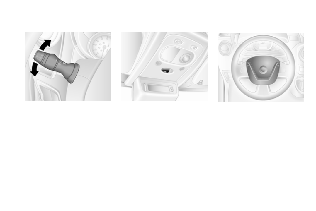
Steering wheel adjustment
Unlock lever, adjust steering wheel,
then engage lever and ensure it is
fully locked.
Do not adjust steering wheel unless
vehicle is stationary and steering
wheel lock has been released.
Airbag system 3 57, Ignition
positions 3 134.

10 In brief
Instrument panel overview

In brief 11
1 Fixed air vents .................... 130
2 Headlight range
adjustment ......................... 110
Ultrasonic parking assist .....163
Traction control system ...... 156
Electronic Stability
Program ............................. 157
3 Side air vents ..................... 129
4 Light switch ........................ 108
Turn and lane-change
signals ................................ 111
High beam and low beam,
headlight flash .................... 109
Sidelights ............................ 108
Automatic light control .......108
Exit lighting ......................... 115
Front fog lights ................... 112
Rear fog light ...................... 112
High beam assist ................ 109
5 Instruments .......................... 89
Transmission display ............ 93
Driver Information Centre .... 102
Trip computer ...................... 104
6 Horn ..................................... 84
Driver airbag ........................ 60
7 Remote control on
steering wheel ....................... 84
Cruise control ..................... 159
8 Windscreen wiper,
windscreen washer system ..85
Trip computer ...................... 104
9 Coin tray ............................... 72
10 Power outlet, USB slot .......... 87
11 Centre air vents .................. 129
12 Storage compartment ........... 72
13 Info-display .......................... 102
14 Front passenger airbag ......... 60
15 Storage compartment ..........72
16 Glovebox .............................. 73
17 Seat belt reminder ................. 96
Front passenger airbag
deactivation ........................... 61
18 Cupholders ........................... 73
19 Climate control system ....... 116
Electronic climate control
system ................................. 118
20 Cigarette lighter .................... 89
Power outlet ......................... 87
21 Gear lever, Manual
transmission ........................ 150
Manual transmission
automated ........................... 150
22 Cruise control and speed
limiter ................................. 159
Manual transmission
automated,
Winter and Laden modes .... 152
Idle speed control ............... 136
Stop-start system ................ 136
ECO mode .......................... 133
23 Ignition switch with
steering wheel lock ............ 134
24 Steering column controls .....84
25 Steering wheel adjustment ..84
26 Bonnet release lever .......... 176
27 Auxiliary heater ................... 123

12 In brief
28 Storage compartment ..........72
Fuse box ............................ 195

In brief 13

14 In brief
Exterior lighting
Turn outer light switch:
: off
7
: sidelights
0
: headlights
9 P
AUTO : automatic light control:
headlights are switched on
and off automatically.
Lighting 3 108, Automatic light
control 3 108, Headlight warning
device 3 103, Adaptive forward
lighting 3 111.
Front and rear fog lights
Turn inner light switch:
: front fog lights
>
ø
: rear fog lights
Front and rear fog lights 3 112,
3 112.
Headlight flash, high beam and low beam
Pull lever.
High beam 3 109, Headlight flash
3 110.
In brief 15
Turn and lane-change signals
lever up : right turn signal
lever down : left turn signal
Turn and lane-change signals
3 111.
Hazard warning flashers
Operated by pressing ¨.
Hazard warning flashers 3 111.
Horn
Press j.
Horn 3 84.

16 In brief
Washer and wiper systems
Windscreen wiper
0 : off
P/AUTO : timed interval wiping or
automatic wiping with
rain sensor
1 : slow
2 : fast
Windscreen wiper 3 85, Wiper
blade replacement 3 184.
Windscreen washer
Pull lever.
short
: wiper swipes once and
pull
long
pull
Windscreen washer 3 85, Washer
fluid 3 180.
washer fluid is sprayed onto
the windscreen
: wiper swipes for a few
strokes and washer fluid is
sprayed onto the
windscreen
Climate control
Heated rear window
Heating is operated by pressing Ü.
Heated rear window 3 41.
Heated exterior mirrors
Pressing Ü also activates the heated
exterior mirrors.
Heated exterior mirrors 3 37.

In brief 17
Demisting and defrosting the windows
Climate control system
● Set temperature control to
warmest level.
● Set fan speed to highest level.
●
Set air distribution control to V.
●
Switch on heated rear window Ü.
● Switch cooling A/C on.
● Open side air vents as required
and direct them towards door
windows.
Climate control system 3 116.
Electronic climate control system
Press V.
Temperature and air distribution are
set automatically and the fan runs at
a high speed.
Electronic climate control system
3 118.
Transmission
Manual transmission
Reverse: with the vehicle stationary,
depress clutch pedal and then pull up
the collar on the selector lever and
engage the gear.
If the gear does not engage, set the
lever to neutral, release the clutch
pedal and depress again; then repeat
gear selection.
Manual transmission 3 150.

18 In brief
Manual transmission automated
N : neutral
: drive position
o
+ : higher gear
- : lower gear
A/M : switch between automatic and
manual mode
R : reverse gear. Engage only
when vehicle is stationary.
Manual transmission automated
3 150.
Starting off
Check before starting off
● Tyre pressure and condition
3 200, 3 246.
● Engine oil level and fluid levels
3 177.
● All windows, mirrors, exterior
lighting and number plates are
free from dirt, snow and ice and
are operational.
● Proper position of mirrors, seats
and seat belts 3 36, 3 44,
3 54.
● Brake function at low speed,
particularly if the brakes are wet.
Starting the engine
● Turn key to position 1.
● Move the steering wheel slightly
to release the steering wheel
lock.
● Operate clutch and brake.
● Do not operate accelerator pedal.
● Turn the key to position 2 for
preheating and wait until control
indicator ! extinguishes in the
Driver Information Centre.
● Turn key to position 3 and
release.
Starting the engine 3 135.

In brief 19
Stop-start system
An Autostop is indicated when control
indicator Ï illuminates green in the
instrument cluster.
Manual transmission
If the vehicle is at low speed or in
standstill and certain conditions are
fulfilled, activate an Autostop as
follows:
● depress the clutch pedal
● move the selector lever to neutral
● release the clutch pedal
To restart the engine, with the
selector lever in neutral, depress the
clutch pedal.
Manual transmission automated
If the vehicle is at a standstill and
certain conditions are fulfilled,
activate an Autostop as follows:
● selector lever in position N (or
A/M)
● depress brake pedal firmly
● do not accelerate
To restart the engine, with the
selector lever in position N (or A/M)
and the parking brake released,
release the brake pedal.
Stop-start system 3 136.
Parking
9 Warning
● Do not park the vehicle on an
easily ignitable surface. The
high temperature of the
exhaust system could ignite the
surface.
● Always apply parking brake
without pressing release
button. Apply as firmly as
possible on a downhill slope or
uphill slope. Depress brake
pedal at the same time to
reduce operating force.
● Switch off the engine.
● If the vehicle is on a level
surface or uphill slope, engage
first gear. On an uphill slope,
turn the front wheels away from
the kerb.
If the vehicle is on a downhill
slope, engage reverse gear.
Turn the front wheels towards
the kerb.

20 In brief
● Close the windows.
● Remove the ignition key from
the ignition switch. Turn the
steering wheel until the
steering wheel lock is felt to
engage.
●
Lock the vehicle by pressing e on
the remote control 3 24.
● Activate the anti-theft alarm
system 3 34.
● The engine cooling fans may run
after the engine has been
switched off 3 176.
Caution
After running at high engine
speeds or with high engine loads,
operate the engine briefly at a low
load or run in neutral for approx.
30 seconds before switching off, in
order to protect the turbocharger.
Keys, locks 3 21, Laying the vehicle
up for a long period of time 3 175.

Keys, doors and windows 21
Keys, doors and windows
Keys, locks ................................... 21
Keys .......................................... 21
Car Pass .................................... 21
Radio remote control ................. 22
Door locks ................................. 23
Manual door locks ..................... 23
Central locking system .............. 24
Power door locks ....................... 27
Automatic locking ...................... 27
Child locks ................................. 28
Doors ........................................... 28
Sliding door ............................... 28
Rear doors ................................. 32
Vehicle security ............................ 34
Anti-theft locking system ...........34
Anti-theft alarm system .............. 34
Immobiliser ................................ 35
Exterior mirrors ............................ 36
Convex shape ........................... 36
Manual adjustment .................... 36
Electric adjustment .................... 36
Folding mirrors .......................... 37
Heated mirrors ........................... 37
Interior mirrors ............................. 38
Manual anti-dazzle .................... 38
Windows ...................................... 38
Windscreen ............................... 38
Manual windows ........................ 39
Power windows ......................... 39
Rear windows ............................ 39
Heated rear window .................. 41
Sun visors .................................. 41
Roof ............................................. 41
Glass panel ............................... 41
Keys, locks
Keys
Caution
Do not attach heavy or bulky items
to the ignition key.
Replacement keys
The key number is specified in the
Car Pass or on a detachable tag.
The key number must be quoted
when ordering replacement keys as it
is a component of the immobiliser
system.
Locks 3 217, Radio remote control
3 22, Central locking system
3 24, Starting the engine 3 135.
Car Pass
The Car Pass contains security
related vehicle data and should
therefore be kept in a safe place.
When the vehicle is taken to a
workshop, this vehicle data is needed
in order to perform certain operations.

22 Keys, doors and windows
Radio remote control
Used to operate:
● central locking system
● anti-theft locking system
● anti-theft alarm system
Depending on model, the vehicle may
use a 2-button or 3-button remote
control.
The remote control has a range of
approx. five metres. It can be affected
by external influences. The hazard
warning flashers confirm operation.
Handle with care, protect it from
moisture and high temperatures and
avoid unnecessary operation.
Fault
If the central locking system cannot
be operated with the remote control,
it may be due to the following:
● The range is exceeded.
● The battery voltage is too low.
● Frequent, repeated operation of
the remote control while not in
range, which will require
reprogramming by a workshop.
● Overload of the central locking
system by operating at frequent
intervals; the power supply is
interrupted for a short time.
● Interference from higher-power
radio waves from other sources.
Unlocking 3 24.
Remote control battery replacement
Replace the battery as soon as the
range reduces.
Batteries do not belong in household
waste. They must be disposed of at
an appropriate recycling collection
point.
Remove screw and open battery
compartment by inserting a coin into
the slot and twisting.
Replace the battery (battery type
CR2016), paying attention to the
installation position.

Keys, doors and windows 23
Reattach both halves of cover
ensuring it engages correctly.
Replace screw and tighten.
Door locks
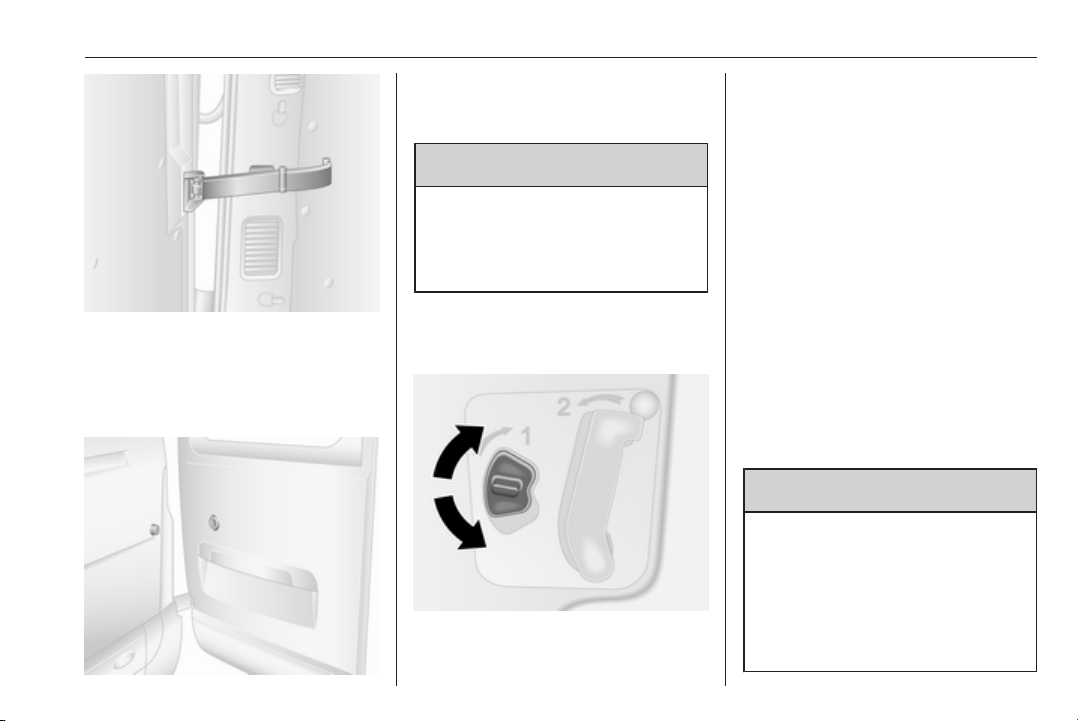
Anti-theft security lock
To prevent the front doors from being
opened from the outside, open the
door and engage the anti-theft
security lock.
Using a suitable tool, turn the lock
switch on the door to the horizontal
locked position. The door cannot be
opened from outside and can only be
opened from inside the vehicle or by
using the manual key.
To disengage, turn the switch to the
unlocked position.
Manual door locks
To unlock the rear doors manually,
turn the key in the right-hand rear
door lock. Open the door by pulling
the handle.
To unlock the front doors manually,
turn the key in the driver's door lock.
Open the front doors by pulling the
handles.
Sliding side door(s) 3 28.

24 Keys, doors and windows
The left-hand rear door is then
released using the lever on the inside
edge of the door.
Always close the left-hand door
before the right-hand door.
Rear doors 3 32.
Central locking system
Unlocks and locks the front doors,
sliding side doors and load
compartment.
With the 3-button remote control, the
front doors and load compartment
(and, depending on vehicle
configuration, the sliding side doors)
can be unlocked and locked
separately.
Note
A short time after unlocking with the
remote control the doors are locked
automatically if no door has been
opened.
Unlocking the vehicle
Operation of central locking system
with the remote control is confirmed
by the hazard warning flashers. The
hazard warning flashers flash once to
indicate the vehicle is unlocked, and
twice to indicate the vehicle is locked.
Unlocking with 2-button remote control
Press c to unlock the front doors.
Press again to unlock entire vehicle.
Unlocking with 3-button remote control
Depending on vehicle configuration:
●
Press c: Front doors and sliding
side doors are unlocked.
Press c again: Load
compartment is also unlocked.
●
Press c: Front doors are
unlocked.
Press c again: Sliding side doors
and the load compartment are
also unlocked.
●
Press c: All doors and the load
compartment are unlocked.

Keys, doors and windows 25
Locking the vehicle
Close all doors and load
compartment. If the doors are not
closed properly, the central locking
system will not work.
Locking with 2-button remote control
Press e: All doors and the load
compartment are locked.
Locking with 3-button remote control
Press e: All doors and the load
compartment are locked.
Note
Where fitted, alarm monitoring of the
passenger compartment 3 34 is
switched off by pressing and holding
e (which is confirmed by an audible
signal).
If this was done unintentionally,
unlock the doors again and press e
briefly to lock the vehicle.
Load compartment
Locking and unlocking load compartment with 2-button remote control
After unlocking the front doors with c,
press c again: Load compartment is
unlocked.
Press e once: Load compartment is
locked.

26 Keys, doors and windows
Locking and unlocking load compartment with 3-button remote control
Depending on vehicle configuration:
● Press G: Load compartment is
locked or unlocked.
● Press G: Load compartment
and sliding side doors are locked
or unlocked.
Central locking switch
Locks or unlocks the doors and load
compartment from inside the
passenger compartment.
Press e to lock or unlock.
LED in switch illuminates when the
vehicle is locked.
Depending on version, if the vehicle
is driven with an open load
compartment, the front doors (and
sliding side doors) can still be locked.
With the ignition switched on, press
and hold e for more than
five seconds. When closing the rear
doors/tailgate, they are locked
automatically.
Automatic locking when exiting the vehicle
Depending on version, the e switch
can also be used to lock all doors and
the load compartment automatically
when closing the front door and
exiting the vehicle:
Remove key from ignition switch then
press and hold the e switch for more
than five seconds; vehicle is locked
when the front door is closed.
Automatic locking after driving off
3 27.
Fault in remote control system
Unlocking
Manually unlock the front door by
turning the key in the lock.
Switch on the ignition and press the
central locking switch e to open all
doors and the load compartment.
Locking
Manually lock the front door by
turning the key in the lock.

Keys, doors and windows 27
Fault in central locking system
Unlocking
Manually unlock the front door by
turning the key in the lock. The other
doors can be opened by pulling the
interior handles.
Locking
Push inside locking knob of all doors
except driver's door. Then close the
driver's door and lock it from the
outside with the key.
Power door locks
Combi, Bus
For safety, it is possible for the driver
to operate the passenger door locks
remotely.
All doors must be fully closed and
automatic locking deactivated 3 27.
To lock, press l side of switch; the
warning light alongside the switch will
flash once (then extinguish) and an
audible warning will sound.
Warning lights in the appropriate
doors extinguish.
To unlock, press 0 side of switch.
Warning lights in the appropriate
doors illuminate continuously.
Fault
In the event of a fault in the system,
the warning light alongside the switch
illuminates continuously and an
audible warning will sound.
Check the doors are manually
unlocked (interior door lock switches).
If necessary, have the cause of the
fault remedied by a workshop.
Automatic locking
Automatic locking after driving off
Depending on version, this security
feature can be configured to
automatically lock all doors and the
load compartment as soon as the
vehicle is driven.

28 Keys, doors and windows
Activation
With the ignition switched on, press
and hold the central locking switch e
for approx. five seconds. An audible
signal confirms activation.
LED in switch illuminates when the
vehicle is locked.
Deactivation
With the ignition switched on, press
and hold e for approx. five seconds.
An audible signal confirms
deactivation.
Child locks
9 Warning
Use the child locks whenever
children are occupying the rear
seats.
Press down the child lock, door
cannot be opened from the inside.
Raise to deactivate.
Doors
Sliding door
Unlock the sliding side door with the
remote control or key (if equipped).
Open the door by pulling the handle
and sliding the door towards the rear.
Open and close the sliding side door
only when the vehicle is at a standstill
with the parking brake applied (on
certain models, a warning chime will
sound when the sliding side door is
open and the parking brake is
released).

Keys, doors and windows 29
The sliding side door can be locked
from inside the vehicle with the
interior lock switch.
Ensure the side door is fully closed
and secure before driving the vehicle.
9 Warning
Take care when operating the
sliding side door. Risk of injury.
Ensure that nothing becomes
trapped during operation and noone is standing within the moving
area.
If the vehicle is parked on a slope,
open sliding doors may move
accidentally on account of their
weight.
Close the sliding doors before
driving off.
9 Danger
Do not drive with the sliding side
door open or ajar, e.g. when
transporting bulky objects, since
toxic exhaust gases, which cannot
be seen or smelled, could enter
the vehicle. This can cause
unconsciousness and even death.
Central locking system 3 24.
Power sliding door
Opening
With vehicle at a standstill and the
parking brake applied, press switch
on instrument panel to open the
power sliding door automatically; the
LED in the switch flashes during
operation.
If the switch is pressed while the
engine is in an Autostop, the engine
will restart automatically.
Stop-start system 3 136.
Note
If the parking brake is not applied
when the switch is pressed, a
warning chime will sound and the
power sliding door will not open.
To stop movement at any time, press
the switch again. Press once more to
continue power sliding door
movement.
Note
If the power sliding door is locked
from the inside with the child lock
active, a warning chime will sound.
Unlock the door manually from the
inside.
Bus
The engine is restarted automatically
when operating the power sliding
door switch during an Autostop.
Stop-start system 3 136.
Closing
Press switch again; the LED flashes
and a chime sounds during operation.
30 Keys, doors and windows
In the event of opening or closing
difficulties, e.g. due to frost, press and
hold the switch to increase power to
the sliding door.
9 Warning
Take care when operating the
power sliding door. Risk of injury,
particularly to children.
Take particular care when the
vehicle is parked on a slope: open
or close the door fully until it
latches into its locking position.
Keep a close watch on the moving
door when operating. Ensure that
nothing becomes trapped during
operation and no-one is standing
within the moving area.
Note
Do not operate power sliding door
too often without engine running as
this will discharge the vehicle
battery.
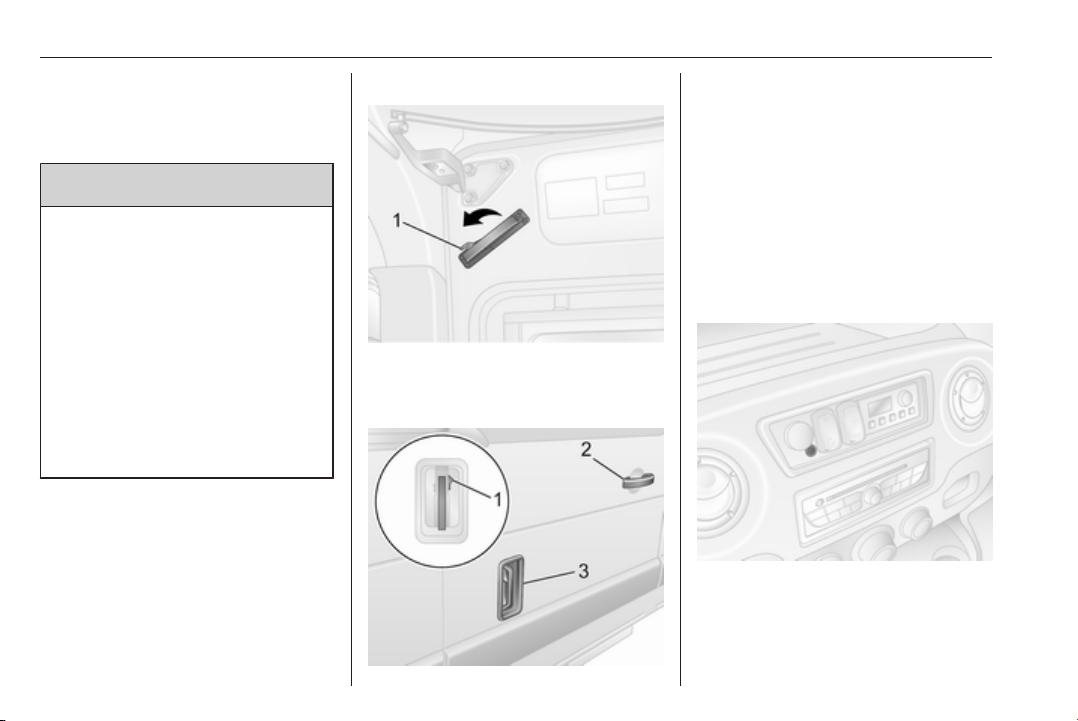
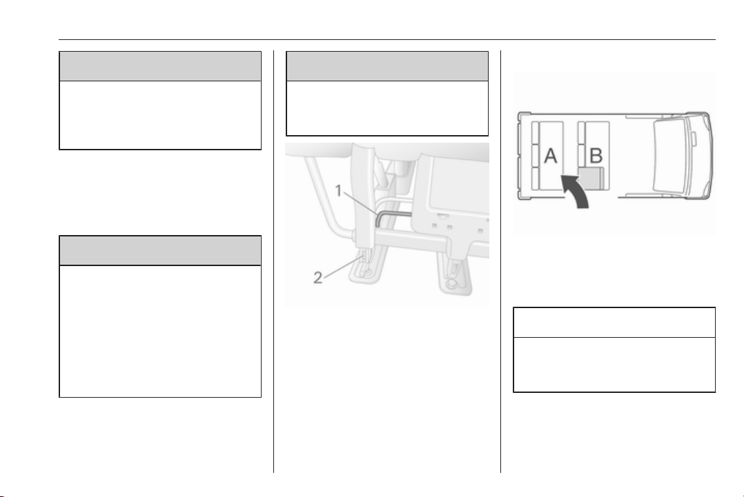
Emergency exit
In an emergency, the sliding side door
can be opened manually after
releasing the interior handle.
Alternatively, if the vehicle is
unlocked, open the door using the
exterior handle (depending on model
variant). Lift the handle (3) to the
second notch position, then slide the
door backwards using the handle (2)
near the front edge of the door.
Reset
If the door has been opened
manually, the power sliding door
system must be reset.
Open the sliding side door halfway
and move the relevant handle to the
first notch position; the warning light
Keys, doors and windows 31
illuminates in the instrument panel.
Then press the button (1) on the
relevant handle.
Move the handle back and forth to
ensure the door actuator motor
operates, then press and hold the
switch on the instrument panel to fully
close the door; the warning light
extinguishes when the system is
reset correctly.
Maintenance
It is the owner's responsibility to have
the drive belt replaced after every
25,000 cycles, and for this purpose a
counter is incorporated in the lower Bpillar. The counter is incremented at
each opening and closing, it is not
possible to reset the counter. Seek
the assistance of a workshop.
If the drive belt should fail, the door
may still be opened and closed
manually.
Fault
If a system fault is detected when
unlocking the doors, an audible
warning will sound and the LED in the
switch illuminates. Check position of
exterior handle. Reset handle if in the
open position and use key to operate
door locks.
Seek the assistance of a workshop if
the fault remains.
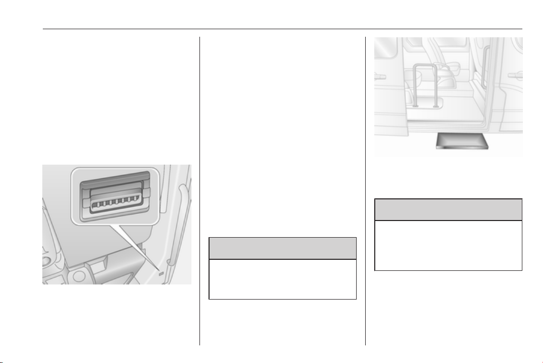
Power side step
9 Warning
Take care when using the power
side step, particularly in wet and
cold weather conditions.
The power side step operates
automatically when the sliding door is
opened or closed.
9 Warning
Ensure there is adequate
clearance to allow the power side
step to fully extend and retract
without obstruction.
32 Keys, doors and windows
Rear doors
Lock and unlock the rear doors with
the remote control or key (if
equipped).
Central locking system 3 24, Manual
door locks 3 23.
To open the right-hand rear door, pull
the exterior handle.
The indicator illuminates during
operation of the power side step. If it
remains illuminated with the door
closed, the step has not retracted, or
the door has not fully latched into its
locking position.
In the event of a failure, manually
retract the power side step by
unscrewing the orange handwheel
located at the rear of the step,
ensuring that there are no obstacles
preventing closure. When the step is
retracted, screw in the orange
handwheel. Seek the assistance of a
workshop.
The right-hand door can also be
opened from inside the vehicle by
pulling the interior handle.
The left-hand rear door is then
released using the lever.
9 Warning
The rear lights may be obscured if
the rear doors are open and the
vehicle is parked on the roadside.
Make other road users aware of
the vehicle, by using a warning
triangle or other equipment
specified in the road traffic
regulations.
The doors are retained in the 90º
position by locking stays.
Keys, doors and windows 33
To open the doors to 180º or further
(depending on model) release locking
stays from the catches on the door
frames and swing doors open to the
desired position.
When opening the doors to 270º, the
doors are retained in the fully open
position by magnets on the body side.
9 Warning
Ensure extended opening doors
are secured when fully opened.
Opened doors may slam closed
due to the force of the wind!
When closing the doors, secure each
locking stay to the catch on the door
frame.
The rear doors can be locked from
inside the vehicle with the interior lock
switch on the inside of the right-hand
door.
Always close the left-hand door
before the right-hand door.
Combi, Bus
In left-hand drive vehicles, the rear
doors are opened from inside the
vehicle by pulling the interior handle.
In right-hand drive vehicles, from
inside the vehicle pull the interior
handle on the right-hand door and
open, then release the left-hand door
by lowering the lever and open.
Always close the left-hand door
before the right-hand door.
9 Danger
Do not drive with the rear doors
open or ajar, e.g. when
transporting bulky objects, since
toxic exhaust gases, which cannot
be seen or smelled, could enter
the vehicle. This can cause
unconsciousness and even death.

34 Keys, doors and windows
Vehicle security
Anti-theft locking system
9 Warning
Do not use the system if there are
people in the vehicle! The doors
cannot be unlocked from the
inside.
The system deadlocks the doors. All
doors must be closed or the system
cannot be activated.
Note
The anti-theft locking system cannot
be activated when the hazard
warning lights or sidelights are
switched on.
Activation and deactivation are not
possible with the central locking
switch.
Activation
Press e twice within three seconds.
Hazard warning lights flash
five times as confirmation.
Deactivation
Unlock the doors by pressing c on the
remote control.
Anti-theft alarm system
The anti-theft alarm system is
operated in conjunction with the
central locking system.
It monitors:
● doors, tailgate, bonnet
● passenger compartment
● load compartment
● ignition
● interruption of alarm siren power
supply
Activation
All doors and the bonnet must be
closed.
Press e to activate anti-theft alarm
system. Hazard warning lights flash
twice to confirm activation.

Keys, doors and windows 35
If the hazard warning lights do not
flash upon activation, a door or the
bonnet is not fully closed.
Note
Changes to the vehicle interior, e.g.
the use of seat covers, and open
windows, could impair the function
of passenger compartment
monitoring.
Deactivation
Unlocking the vehicle or switching on
the ignition deactivates the anti-theft
alarm system. Hazard warning lights
flash once to confirm deactivation.
Note
If the alarm has been triggered,
unlocking the vehicle with the key
will not stop the alarm siren. To stop
the siren, switch on the ignition. The
hazard warning lights will not flash
upon deactivation if the alarm has
been triggered.
Activation without monitoring of passenger compartment
Switch off monitoring of the
passenger compartment when
people or animals are being left in the
vehicle, or if the auxiliary heater
3 123 is set for a timed or remote
controlled start.
Depending on vehicle configuration:
●
press and hold e, or
● switch ignition on and off twice
quickly, then close doors and
activate the anti-theft alarm
system
An audible signal will sound as
confirmation.
The status will remain until the doors
are unlocked.
Alarm
When triggered, the alarm sounds via
a separate battery-backed power
sounder, and the hazard warning
lights flash simultaneously. The
number and duration of alarm signals
are stipulated by legislation.
If the vehicle battery is disconnected
or its power supply is interrupted, the
alarm siren will be triggered. First
deactivate the anti-theft alarm system
if the vehicle battery must be
disconnected.
To silence the alarm siren (if
triggered) and therefore deactivate
the anti-theft alarm system, reconnect
vehicle battery and unlock vehicle
with remote control button c (or
switch on the ignition).
Immobiliser
The system is part of the ignition
switch and checks whether the
vehicle is allowed to be started with
the key being used.

36 Keys, doors and windows
The immobiliser is activated
automatically after the key has been
removed from the ignition switch and
also if the key is left in the ignition
switch when the engine is turned off.
If the engine cannot be started, switch
off the ignition and remove key, wait
approx. two seconds and then repeat
the start attempt. If start attempt is
unsuccessful, attempt to start the
engine using the spare key and seek
the assistance of a workshop.
Note
Radio Frequency Identification
(RFID) tags may cause interference
with the key. Do not have it placed
near the key when starting the
vehicle.
Note
The immobiliser does not lock the
doors. You should always lock the
vehicle after leaving it and switch on
the anti-theft alarm system 3 24,
3 34.
Exterior mirrors
Convex shape
The convex exterior mirror contains
an aspherical area and reduces blind
spots. The shape of the mirror makes
objects appear smaller, which will
affect the ability to estimate
distances.
Manual adjustment
Adjust mirrors by swivelling in
required direction.
The lower mirrors are not adjustable.
Electric adjustment
Switch on ignition to operate electric
exterior mirrors.
Select the relevant exterior mirror by
switching the control to the left or
right, then swivel the control to adjust
the mirror.
No mirror is selected when the control
is in the centre position.
The lower mirrors are not adjustable.

Keys, doors and windows 37
Folding mirrors
For pedestrian safety, the exterior
mirrors will swing out of their normal
mounting position if they are struck
with sufficient force. Reposition the
mirror by applying slight pressure to
the mirror housing.
Parking position
The exterior mirrors can be folded in
by pressing gently on the outer edge
of the housing, e.g. when in a
confined parking situation.
Heated mirrors
Operated by pressing Ü on either
system. LED illuminates in button
during operation.
Heating works with the engine
running and is switched off
automatically after a short time.
Climate control system 3 116.
Electronic climate control system
3 118.
38 Keys, doors and windows
Interior mirrors
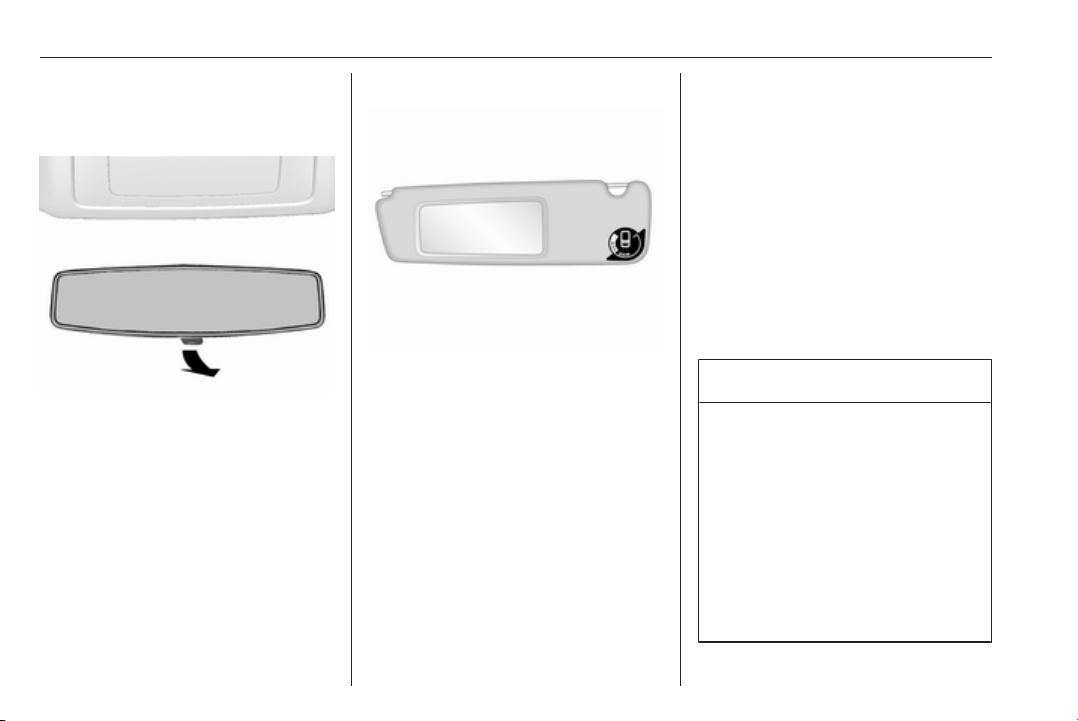
Manual anti-dazzle
To reduce dazzle, adjust the lever on
the underside of the mirror housing.
Wide view mirror
Depending on vehicle, a large convex
mirror is located in the front
passenger sun visor which helps to
increase visibility and reduce blind
spots.
Windows
Windscreen
Windscreen stickers
Do not attach stickers, e.g. toll road
stickers or similar, on the windscreen
in the area of the interior mirror.
Otherwise the detection zone of the
sensor in the mirror housing could be
restricted.
Windscreen replacement
Caution
If the vehicle has a front-looking
camera sensor for the driver
assistance systems, it is very
important that any windscreen
replacement is performed
accurately according to Opel
specifications. Otherwise, these
systems may not work properly
and there is a risk of unexpected
behaviour and/or messages from
these systems.

Keys, doors and windows 39
Manual windows
The door windows can be opened or
closed with the window cranks.
Power windows
9 Warning
Take care when operating the
power windows. Risk of injury,
particularly to children.
Keep a close watch on the
windows when closing them.
Ensure that nothing becomes
trapped in them as they move.
Switch on ignition to operate power
windows.
Operate the switch for the respective
window by pushing to open or pulling
to close.
For vehicles with automatic opening
feature for the driver's door window;
when opening, operate the switch
again to stop window movement.
In the event of closing difficulties due
to frost or the like, operate the switch
several times to close the window in
stages.
Overload
If the windows are repeatedly
operated within short intervals, the
window operation is disabled for
some time.
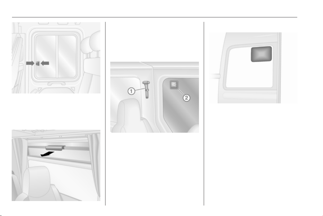
Rear windows
Sliding side windows
Press catch and slide window to
open. Ensure catch engages when
closing.
40 Keys, doors and windows
Press catch and slide window to
open. Ensure catch engages when
closing.
Opening side windows
Pull handle to open window.
Note
Depending on vehicle, some
windows may not open fully.
Emergency exit
To provide an emergency exit from
the vehicle, use hammer 1 to strike
glass 2.
Depending on version, emergency
exit may be via the roof glass panel
3 41.
Rear reversing lens
A rear reversing lens may be fitted to
the rear window.
The rear reversing lens assists the
driver when reversing by reducing
blind spots.
Keys, doors and windows 41
Heated rear window
Operated by pressing Ü on either
system. LED illuminates in button
during operation.
Heating works with the engine
running and is switched off
automatically after a short time.
Climate control system 3 116.
Electronic climate control system
3 118.
Sun visors
The sun visors can be folded down or
swivelled to the side to prevent
dazzling.
If the sun visors have integral mirrors,
the mirror covers should be closed
when driving.
Sun visors may also feature a holder
for parking tickets etc.
Wide view mirror 3 38.
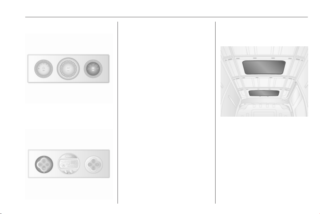
Roof
Glass panel
Depending on model variant, the load
compartment may incorporate a
single or a double glass roof panel.

42 Keys, doors and windows
Emergency exit
In an emergency, the glass can be
broken. Use the hammer provided to
strike the glass panel.
Depending on version, emergency
exit may alternatively be via the side
windows 3 39.

Seats, restraints 43
Seats, restraints
Head restraints ............................ 43
Front seats ................................... 44
Seat position .............................. 44
Seat adjustment ........................ 45
Armrest ...................................... 49
Heating ...................................... 50
Rear seats ................................... 50
Seat belts ..................................... 53
Three-point seat belt ................. 54
Airbag system .............................. 57
Front airbag system ................... 60
Side airbag system .................... 61
Airbag deactivation .................... 61
Child restraints ............................. 63
Child restraint systems .............. 63
Child restraint installation
locations ................................... 65
Head restraints
Position
9 Warning
Only drive with the head restraint
set to the proper position.
The upper edge of the head restraint
should be at upper head level. If this
is not possible for extremely tall
people, set to highest position, and
set to lowest position for small people.
Adjustment
Pull up to raise or press button and
lower head restraint. Ensure the head
restraint engages.
44 Seats, restraints
Depending on version, head
restraints can also be tilted forwards
or backwards. Push or pull the lower
part of the head restraint to adjust.
Note
Approved accessories may only be
attached to the front passenger seat
head restraint if the seat is not in use.
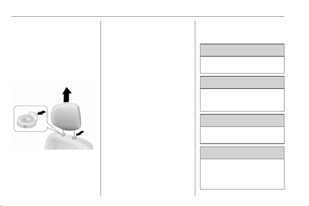
Removal
E.g. when using a child restraint
system 3 63.
First tilt the backrest forwards, then
pull up head restraint to uppermost
position. Press both release buttons
and pull the head restraint upwards to
remove.
Stow head restraints securely in load
compartment.
Do not drive with head restraints
removed if the seat is occupied.
Installation
First tilt the backrest forwards, then
insert the rods of the head restraint
into their holes.
Lower head restraint as far as
possible, then raise head restraint
(press both release buttons first, if
necessary) until it engages securely
in desired position.
Front seats
Seat position
9 Warning
Only drive with the seat correctly
adjusted.
9 Danger
Do not sit nearer than 25 cm from
the steering wheel, to permit safe
airbag deployment.
9 Warning
Never adjust seats while driving as
they could move uncontrollably.
9 Warning
Never store any loose objects
under the seats.
Underseat storage, storage box
3 74.
Seats, restraints 45
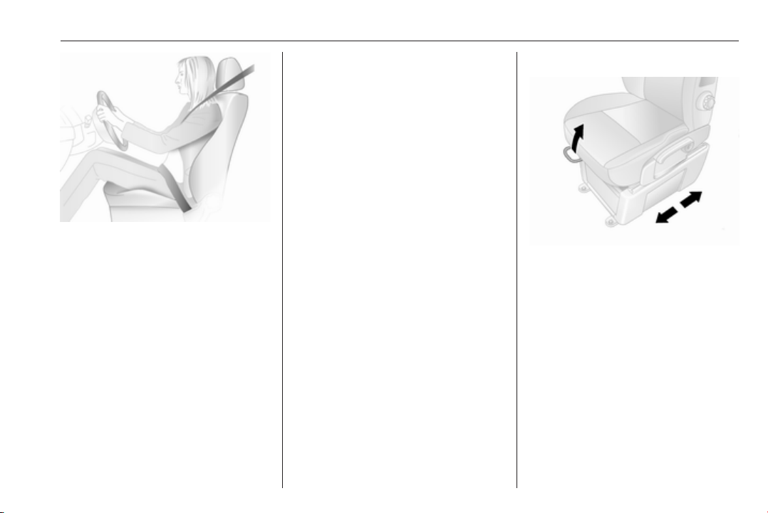
● Sit with buttocks as far back
against the backrest as possible.
Adjust the distance between the
seat and the pedals so that legs
are slightly angled when pressing
the pedals. Slide the front
passenger seat as far back as
possible.
● Set seat height high enough to
have a clear field of vision on all
sides and of all display
instruments. There should be at
least one hand of clearance
between head and the roof
frame. Thighs should rest lightly
on the seat without pressing into
it.
● Sit with shoulders as far back
against the backrest as possible.
Set the backrest rake so that it is
possible to reach the steering
wheel with arms slightly bent.
Maintain contact between
shoulders and the backrest when
turning the steering wheel. Do
not angle the backrest too far
back. We recommend a
maximum rake of approx. 25°.
● Adjust seat and steering wheel in
a way that the wrist rests on top
of the steering wheel while the
arm is fully extended and
shoulders on the backrest.
● Adjust the steering wheel 3 84.
● Adjust the head restraint 3 43.
● Adjust the height of the seat belt
3 54.
● Adjust the lumbar support so that
it supports the natural shape of
the spine 3 45.
Seat adjustment
Drive only with engaged seats and
backrests.
Longitudinal adjustment
Pull handle, slide seat, release
handle.
Try to move the seat back and forth to
ensure that the seat is locked in place.

46 Seats, restraints
Suspension seat longitudinal adjustment
Pull handle, slide seat, release
handle.
Try to move the seat back and forth to
ensure that the seat is locked in place.
Backrest inclination
Pull lever, adjust inclination and
release lever. Allow the seat to
engage audibly.
Suspension seat backrest inclination
Pull lever, adjust inclination and
release lever. Allow the seat to
engage audibly.

Seats, restraints 47
Seat height
Lever pumping motion
up : seat higher
down : seat lower
Suspension seat height
Pull up front release lever up to adjust
height of front part of seat.
Pull up rear release lever to adjust
height of rear part of seat.
Lumbar support
Adjust lumbar support to suit personal
requirements.
Increasing and decreasing support:
turn the handwheel while relieving the
load on the backrest.
48 Seats, restraints
Suspension seat lumbar support
Adjust lumbar support to suit personal
requirements.
Operate hand pump repeatedly
(located on underside of unit) to
increase firmness.
Press release button (located at front
of unit) to decrease firmness.
Suspension seat sensitivity
Rotate knob to adjust the sensitivity of
the suspension seat.
turn right : more stiff
turn left : less stiff
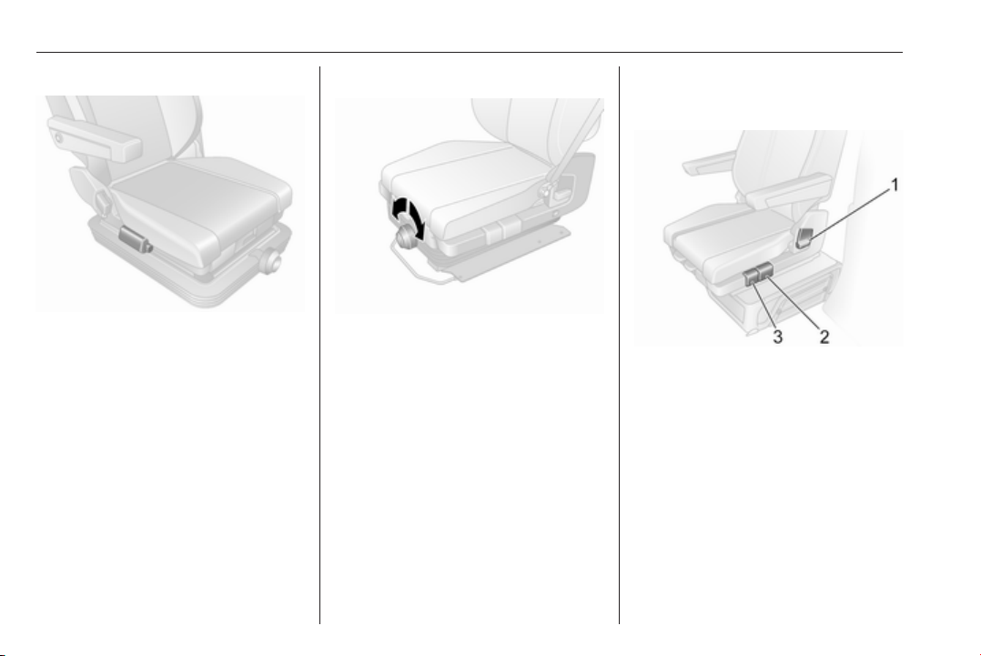
Swivel seat adjustment
Seat positioning
Move handle 2, slide seat, release
handle.
Try to move the seat back and forth to
ensure that the seat is locked in place.
Seat backrests
Pull lever 1, adjust inclination and
release lever. Allow the seat to
engage audibly.
Seat base angle
Move handle 3 to adjust angle of seat
base.

Seats, restraints 49
Lumbar support
Adjust lumbar support to suit personal
requirements.
Operate hand pump 8 repeatedly
(located on underside of unit) to
increase firmness.
Press release button 7 to decrease
firmness.
Seat base positioning
Lift handle 5, move seat base
backwards or forwards, release
handle.
Armrests
To adjust the height of the armrests,
turn control knob 4 or 9.
Swivelling the seat
The driver's seat can be swivelled up
to 180° from the forward-facing
position, e.g. for easier access to the
load compartment area when the
vehicle is stationary and the engine is
switched off.
Before swivelling the seat, make the
following preparations:
● Unfasten seat belt.
● Fold up the armrests.
● Slide seat as far back as
possible.
● Set seat base angle to its lowest
position.
● Adjust backrest inclination to
vertical position.
● Open the driver's door.
Lift handle 6, swivel seat from the
forward-facing position, release
handle.
Always return the seat to the forwardfacing position before driving and
ensure the seat is locked in place
before starting off.
Armrest
Armrests can be folded up when not
required.
50 Seats, restraints
Heating
Press ß for the respective seat; LED
in switch illuminates. Press other end
of rocker switch to turn seat heating
off.
Vehicles with suspension seat: switch
ß is located below the backrest
release lever on the outboard side of
the seat.
Seat heating is thermostatically
controlled and switches off
automatically when seat temperature
is sufficient. LED also illuminates
when the system is on, not just when
heating is active.
Prolonged use for people with
sensitive skin is not recommended.
Seat heating is operational when the
engine is running.
Rear seats
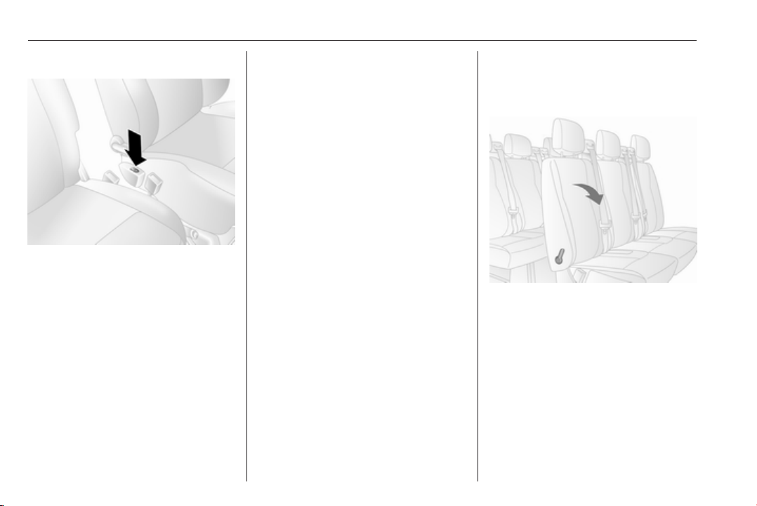
Rear seat access
To facilitate access to the 3rd row
seats (where fitted), open sliding side
door and pull release lever on folding
access seat in the 2nd row and fold
the seat backrest forwards. If
necessary, unfasten seat belts from
their buckles.
Seats, restraints 51
9 Warning
Ensure that the backrest returns to
its correct position and the seat
belt buckles are fastened
securely.
Fastening and unfastening seat belt
3 54.
Sliding door 3 28.
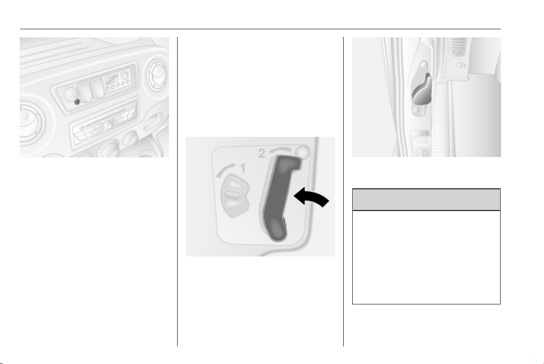
Removable rear seats
9 Warning
When rear seats are being
removed, keep hands and feet
away from the moving area.
Never remove seats while driving
as they could move uncontrollably.
Ensure that the rear seats and
backrests are fully engaged before
occupying the rear seats.
Removal
On some variants, the load
compartment area can be increased
by removing the rear seats.
Warning
9
Removable rear seats are heavy!
Do not attempt to remove without
assistance.
● Pull up lever
the seat; the pins 2 visibly
protrude to indicate that the seat
is unlocked.
● Move the seat towards the rear to
release from the floor anchor
points.
● Lift seat to remove.
1 on both sides of
Installation
When re-installing seats, always
ensure that the row with the folding
access seat B is positioned correctly
in front of the fixed seat row A.
Caution
The 2nd and 3rd row seats are not
interchangeable and must be fitted
back into their original position.

52 Seats, restraints
Note
Make sure that the anchor points are
clean before installing the seat. They
should be free from grit or any other
item which may prevent the seat
from locking securely.
Position the seat guides immediately
behind the front floor anchor points,
and slide forwards to engage.
The seat locks automatically and the
pins 3 will no longer be visible, to
indicate that the seat is locked.
Caution
When installing the rear seats,
ensure they are properly located
on the floor anchor points and that
the locking catches are fully
engaged.
Consult a workshop if the seats
cannot be locked securely in position.
Bus
Removal
9 Warning
Removable rear seats are heavy!
Do not attempt to remove without
assistance.
Using the tool from the tool kit located
in the glovebox, turn levers to unlock
the seat:
1. Release the outboard fixing.
2. Release the inboard fixing
(located at the base of the seat).

Seats, restraints 53
3. Lift the seat from the rear.
4. Pull the seat towards the centre of
the vehicle to release the seat
completely from its anchor points.
Installation
Note
Make sure that the anchor points are
clean before installing the seat. They
should be free from grit or any other
item which may prevent the seat
from locking securely.
1. Position the seat over the anchor
points.
2. Lower the seat until it audibly
engages in the anchor points.
3. Ensure the seat is locked securely
in position by trying to move the
seat back and forth and from left
to right.
Repeat installation procedure if
necessary.
Consult a workshop if the seat cannot
be locked securely in position.
Seat belts
The seat belts are locked during
heavy acceleration or deceleration of
the vehicle, holding the occupants in
the sitting position. Therefore, the risk
of injury is considerably reduced.
9 Warning
Fasten seat belt before each trip.
In the event of an accident, people
not wearing seat belts endanger
their fellow occupants and
themselves.
Seat belts are designed to be used by
only one person at a time. Child
restraint system 3 63.
Periodically check all parts of the belt
system for damage and proper
functionality.
Have damaged components
replaced. After an accident, have the
belts and triggered belt pretensioners
replaced by a workshop.
Note
Make sure that the belts are not
damaged by shoes or sharp-edged
objects or trapped. Prevent dirt from
getting into the belt retractors.
Seat belt reminder
Depending on version, both front
seats may be equipped with a seat
belt reminder, indicated by control
indicator X in the instrument panel
3 93, 3 96.
Belt force limiters
On the front seats, stress on the body
is reduced by the gradual release of
the belt during a collision.
54 Seats, restraints
Belt pretensioners
In the event of a head-on or rear-end
collision of a certain severity, the front
seat belts are tightened.
9 Warning
Incorrect handling (e.g. removal or
fitting of belts) can trigger the belt
pretensioners.
Deployment of the belt pretensioners
is indicated by continuous illumination
of control indicator v 3 96.
Triggered belt pretensioners must be
replaced by a workshop. Belt
pretensioners can only be triggered
once.
Note
Do not affix or install accessories or
other objects that may interfere with
the operation of the belt
pretensioners. Do not make any
modifications to belt pretensioner
components as this will invalidate
the vehicle type approval.
Three-point seat belt
Seat belts on the front seats
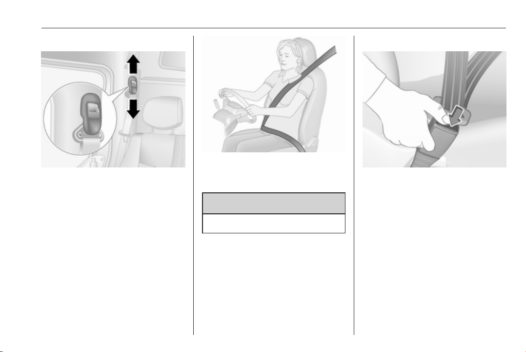
Fasten
Withdraw the belt from the retractor,
guide it untwisted across the body
and insert the latch plate into the
buckle.
Tighten the lap belt regularly whilst
driving by pulling the shoulder belt.
Loose or bulky clothing prevents the
belt from fitting snugly. Do not place
objects such as handbags or mobile
phones between the belt and your
body.
9 Warning
The belt must not rest against hard
or fragile objects in the pockets of
your clothing.
Seat belt reminder X 3 96.
Seats, restraints 55
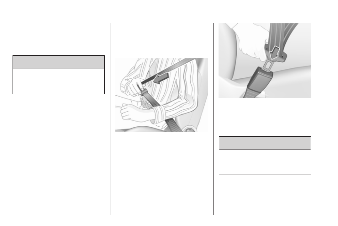
Height adjustment
1. Pull belt out slightly.
2. Shift the height adjustment
upwards or press button to
disengage and push the height
adjustment downwards.
Adjust the height so that the belt lies
across the shoulder. It must not lie
across the throat or upper arm.
9 Warning
Do not adjust while driving.
Unfasten
To unfasten belt, press red button on
belt buckle. The seat belt retracts
automatically.

56 Seats, restraints
Seat belts on the rear seats
Withdraw belt 1 from the retractor,
guide it untwisted across the body
and ensure that latch plate 2 is fully
engaged in its buckle 3 by pulling on
the latch plate 2.
The lap belt 5 must be worn closely
over the thighs and against the pelvis.
To tighten, pull on free section 6 of the
belt. To loosen, turn adjusting buckle
4 until it is at 90 ° to the belt and press
the adjusting buckle 4 while pulling
lap belt 5.
Loose or bulky clothing prevents the
belt from fitting snugly. Do not place
objects such as handbags or mobile
phones between the belt and your
body.
9 Warning
The belt must not rest against hard
or fragile objects in the pockets of
your clothing.
To unfasten, press red button on belt
buckle 3 to release the latch plate 2.
Guide the seat belt 1 as it retracts
automatically.
Warning
9
Ensure that the rear seats and
backrests are fully engaged before
occupying the rear seats.
Rear seats 3 50.
Caution
To avoid damage to the vehicle,
always fasten the rear seat belts
even if the seats are not occupied.
Using the seat belt while pregnant
Seats, restraints 57
9 Warning
The lap belt must be positioned as
low as possible across the pelvis
to prevent pressure on the
abdomen.
Airbag system
The airbag system consists of a
number of individual systems
depending on the scope of
equipment.
When triggered the airbags inflate
within milliseconds. They also deflate
so quickly that it is often unnoticeable
during the collision.
9 Warning
If handled improperly the airbag
systems can be triggered in an
explosive manner.
Note
The airbag systems and belt
pretensioner control electronics are
located in the centre console area.
Do not put any magnetic objects in
this area.
Do not fix any objects onto the airbag
covers and do not cover them with
other materials.
Each airbag is triggered only once.
Have deployed airbags replaced by
a workshop. Furthermore, it may be
necessary to have the steering
wheel, the instrument panel, parts of
the panelling, the door seals,
handles and the seats replaced.
Do not make any modifications to
the airbag system as this will
invalidate the vehicle type approval.
When the airbags inflate escaping hot
gases may cause burns.
Control indicator v for airbag systems
3 96.
Child restraint systems on front
passenger seat with airbag
systems
Warning according to ECE R94.02:

58 Seats, restraints
EN: NEVER use a rear-facing child
restraint system on a seat protected
by an ACTIVE AIRBAG in front of it,
DEATH or SERIOUS INJURY to the
CHILD can occur.
DE: Nach hinten gerichtete
Kindersitze NIEMALS auf einem Sitz
verwenden, der durch einen davor
befindlichen AKTIVEN AIRBAG
geschützt ist, da dies den TOD oder
SCHWERE VERLETZUNGEN DES
KINDES zur Folge haben kann.
FR: NE JAMAIS utiliser un siège
d'enfant orienté vers l'arrière sur un
siège protégé par un COUSSIN
GONFLABLE ACTIF placé devant lui,
sous peine d'infliger des
BLESSURES GRAVES, voire
MORTELLES à l'ENFANT.
ES: NUNCA utilice un sistema de
retención infantil orientado hacia
atrás en un asiento protegido por un
AIRBAG FRONTAL ACTIVO. Peligro
de MUERTE o LESIONES GRAVES
para el NIÑO.
RU: ЗАПРЕЩАЕТСЯ
устанавливать детское
удерживающее устройство лицом
назад на сиденье автомобиля,
оборудованном фронтальной
подушкой безопасности, если
ПОДУШКА НЕ ОТКЛЮЧЕНА! Это
может привести к СМЕРТИ или
СЕРЬЕЗНЫМ ТРАВМАМ
РЕБЕНКА.
NL: Gebruik NOOIT een achterwaarts
gericht kinderzitje op een stoel met
een ACTIEVE AIRBAG ervoor, om
DODELIJK of ERNSTIG LETSEL van
het KIND te voorkomen.
DA: Brug ALDRIG en bagudvendt
autostol på et forsæde med AKTIV
AIRBAG, BARNET kan komme I
LIVSFARE eller komme ALVORLIGT
TIL SKADE.
SV: Använd ALDRIG en bakåtvänd
barnstol på ett säte som skyddas med
en framförvarande AKTIV AIRBAG.
DÖDSFALL eller ALLVARLIGA
SKADOR kan drabba BARNET.
FI: ÄLÄ KOSKAAN sijoita taaksepäin
suunnattua lasten turvaistuinta
istuimelle, jonka edessä on
AKTIIVINEN TURVATYYNY, LAPSI
VOI KUOLLA tai VAMMAUTUA
VAKAVASTI.
NO: Bakovervendt
barnesikringsutstyr må ALDRI brukes
på et sete med AKTIV
KOLLISJONSPUTE foran, da det kan
føre til at BARNET utsettes for
LIVSFARE og fare for ALVORLIGE
SKADER.
PT: NUNCA use um sistema de
retenção para crianças voltado para
trás num banco protegido com um
AIRBAG ACTIVO na frente do
mesmo, poderá ocorrer a PERDA DE
VIDA ou FERIMENTOS GRAVES na
CRIANÇA.
IT: Non usare mai un sistema di
sicurezza per bambini rivolto
all'indietro su un sedile protetto da
AIRBAG ATTIVO di fronte ad esso:
pericolo di MORTE o LESIONI
GRAVI per il BAMBINO!
EL: ΠΟΤΕ μη χρησιμοποιείτε παιδικό
κάθισμα ασφαλείας με φορά προς τα
πίσω σε κάθισμα που προστατεύεται
από μετωπικό ΕΝΕΡΓΟ ΑΕΡΟΣΑΚΟ,
διότι το παιδί μπορεί να υποστεί
ΘΑΝΑΣΙΜΟ ή ΣΟΒΑΡΟ
ΤΡΑΥΜΑΤΙΣΜΟ.

Seats, restraints 59
PL: NIE WOLNO montować fotelika
dziecięcego zwróconego tyłem do
kierunku jazdy na fotelu, przed
którym znajduje się WŁĄCZONA
PODUSZKA POWIETRZNA.
Niezastosowanie się do tego
zalecenia może być przyczyną
ŚMIERCI lub POWAŻNYCH
OBRAŻEŃ u DZIECKA.
TR: Arkaya bakan bir çocuk emniyet
sistemini KESİNLİKLE önünde bir
AKTİF HAVA YASTIĞI ile
korunmakta olan bir koltukta
kullanmayınız. ÇOCUK ÖLEBİLİR
veya AĞIR ŞEKİLDE
YARALANABİLİR.
UK: НІКОЛИ не використовуйте
систему безпеки для дітей, що
встановлюється обличчям назад,
на сидінні з УВІМКНЕНОЮ
ПОДУШКОЮ БЕЗПЕКИ, інакше це
може призвести до СМЕРТІ чи
СЕРЙОЗНОГО ТРАВМУВАННЯ
ДИТИНИ.
HU: SOHA ne használjon hátrafelé
néző biztonsági gyerekülést előlről
AKTÍV LÉGZSÁKKAL védett ülésen,
mert a GYERMEK HALÁLÁT vagy
KOMOLY SÉRÜLÉSÉT okozhatja.
HR: NIKADA nemojte koristiti sustav
zadržavanja za djecu okrenut prema
natrag na sjedalu s AKTIVNIM
ZRAČNIM JASTUKOM ispred njega,
to bi moglo dovesti do SMRTI ili
OZBILJNJIH OZLJEDA za DIJETE.
SL: NIKOLI ne nameščajte otroškega
varnostnega sedeža, obrnjenega v
nasprotni smeri vožnje, na sedež z
AKTIVNO ČELNO ZRAČNO
BLAZINO, saj pri tem obstaja
nevarnost RESNIH ali SMRTNIH
POŠKODB za OTROKA.
SR: NIKADA ne koristiti bezbednosni
sistem za decu u kome su deca
okrenuta unazad na sedištu sa
AKTIVNIM VAZDUŠNIM
JASTUKOM ispred sedišta zato što
DETE može da NASTRADA ili da se
TEŠKO POVREDI.
MK: НИКОГАШ не користете детско
седиште свртено наназад на
седиште заштитено со АКТИВНО
ВОЗДУШНО ПЕРНИЧЕ пред него,
затоа што детето може ДА ЗАГИНЕ
или да биде ТЕШКО ПОВРЕДЕНО.
BG: НИКОГА не използвайте
детска седалка, гледаща назад,
върху седалка, която е защитена
чрез АКТИВНА ВЪЗДУШНА
ВЪЗГЛАВНИЦА пред нея - може да
се стигне до СМЪРТ или
СЕРИОЗНО НАРАНЯВАНЕ на
ДЕТЕТО.
RO: Nu utilizaţi NICIODATĂ un scaun
pentru copil îndreptat spre partea din
spate a maşinii pe un scaun protejat
de un AIRBAG ACTIV în faţa sa;
acest lucru poate duce la DECESUL
sau VĂTĂMAREA GRAVĂ a
COPILULUI.
CS: NIKDY nepoužívejte dětský
zádržný systém instalovaný proti
směru jízdy na sedadle, které je
chráněno před sedadlem AKTIVNÍM
AIRBAGEM. Mohlo by dojít k
VÁŽNÉMU PORANĚNÍ nebo ÚMRTÍ
DÍTĚTE.
SK: NIKDY nepoužívajte detskú
sedačku otočenú vzad na sedadle
chránenom AKTÍVNYM AIRBAGOM,
pretože môže dôjsť k SMRTI alebo
VÁŽNYM ZRANENIAM DIEŤAŤA.
LT: JOKIU BŪDU nemontuokite atgal
atgręžtos vaiko tvirtinimo sistemos
sėdynėje, prieš kurią įrengta AKTYVI
ORO PAGALVĖ, nes VAIKAS GALI
ŽŪTI arba RIMTAI SUSIŽALOTI.
60 Seats, restraints
LV: NEKĀDĀ GADĪJUMĀ
neizmantojiet uz aizmuguri vērstu
bērnu sēdeklīti sēdvietā, kas tiek
aizsargāta ar tās priekšā uzstādītu
AKTĪVU DROŠĪBAS SPILVENU, jo
pretējā gadījumā BĒRNS var gūt
SMAGAS TRAUMAS vai IET BOJĀ.
ET: ÄRGE kasutage tahapoole
suunatud lapseturvaistet istmel, mille
ees on AKTIIVSE TURVAPADJAGA
kaitstud iste, sest see võib
põhjustada LAPSE SURMA või
TÕSISE VIGASTUSE.
MT: QATT tuża trażżin għat-tfal li
jħares lejn in-naħa ta’ wara fuq sit
protett b’AIRBAG ATTIV quddiemu;
dan jista’ jikkawża l-MEWT jew
ĠRIEĦI SERJI lit-TFAL.
Beyond the warning required by
ECE R94.02, for safety reasons a
forward-facing child restraint system
must only be used subject to the
instructions and restrictions in the
table 3 65.
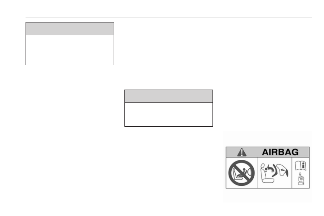
The airbag label may be located on
both sides of the front passenger sun
visor.
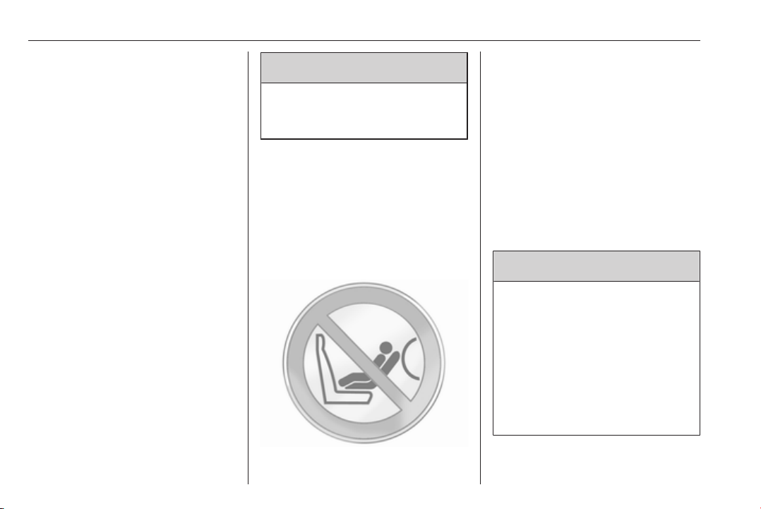
Danger
9
Do not use a child restraint system
on the passenger seat with active
front airbag.
Airbag deactivation 3 61.
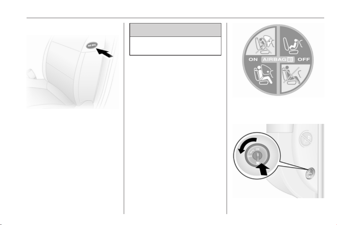
Front airbag system
The front airbag system consists of
one airbag in the steering wheel and
one in the instrument panel on the
front passenger side. These can be
identified by the word AIRBAG.
Additionally there is a warning label
on the side of the instrument panel,
visible when the front passenger door
is open.
The front airbag system is triggered in
the event of an accident of a certain
severity. The ignition must be
switched on.
The inflated airbags cushion the
impact, thereby reducing the risk of
injury to the upper body and head of
the front seat occupants
considerably.
9 Warning
Optimum protection is only
provided when the seat is in the
proper position.
Seat position 3 44.
Keep the area in which the airbag
inflates clear of obstructions.
Fasten the seat belt correctly and
engage securely. Only then is the
airbag able to protect.
Seats, restraints 61
Side airbag system
The side airbag system consists of an
airbag in each front seat backrest.
This can be identified by the word
AIRBAG.
The side airbag system is triggered in
the event of an accident of a certain
severity. The ignition must be
switched on.
The inflated airbags cushion the
impact, thereby reducing the risk of
injury to the upper body and pelvis in
the event of a side-on collision
considerably.
Warning
9
Keep the area in which the airbag
inflates clear of obstructions.
Note
Only use protective seat covers that
have been approved for the vehicle.
Be careful not to cover the airbags.
Airbag deactivation
Front airbag and side airbag systems
for the front passenger seat must be
deactivated if a child restraint system
is to be fitted on this seat, in
accordance with the instructions in
the child restraint installation location
tables 3 65.
The belt pretensioners and all driver
airbag systems will remain active.
The front passenger airbag system
can be deactivated via a switch on the
side of the instrument panel.

62 Seats, restraints
With the ignition off, open the front
door, push switch in and rotate anticlockwise to the OFF position.
Front passenger seat airbags are
deactivated and will not inflate in the
event of a collision. Control indicator
W 3 96 illuminates continuously in
the instrument panel and a
corresponding message appears in
the Driver Information Centre 3 102.
A child restraint system can be
installed in accordance with the
installation locations chart 3 65. An
adult must not occupy the front
passenger seat.
9
Danger
Deactivate passenger airbag only
in combination with the use of a
child restraint system, subject to
the instructions and restrictions in
the table 3 65.
Otherwise, there is a risk of fatal
injury for a person occupying a
seat with a deactivated front
passenger airbag.
As long as control indicator W is not
illuminated, the airbag systems for
the front passenger seat will inflate in
the event of a collision.
If control indicator A remains
illuminated together with v, this
indicates a fault within the system.
The switch position may have been
changed inadvertently with the
ignition on. Turn ignition off and on
again and reset the switch position. If
A and v still remain illuminated,
seek the assistance of a workshop.
Change status only when the vehicle
is stopped with the ignition off. Status
remains until the next change.
Control indicator W for airbag
deactivation 3 96.
Seats, restraints 63
Child restraints
Child restraint systems
9 Warning
When using a child restraint
system on the front passenger
seat, the airbag systems for the
front passenger seat must be
deactivated; if not, the triggering of
the airbags poses a risk of fatal
injury to the child.
This is especially the case if rearfacing child restraint systems are
used on the front passenger seat.
Airbag deactivation 3 61.
Airbag label 3 57.
We recommend a child restraint
system which is tailored specifically to
the vehicle. For further information,
contact your workshop.
When a child restraint system is being
used, pay attention to the following
usage and installation instructions
and also those supplied with the child
restraint system.
Always comply with local or national
regulations. In some countries, the
use of child restraint systems is
forbidden on certain seats.
Child restraint systems can be
fastened with:
● Three-point seat belt
● ISOFIX brackets
● Top-Tether
Three-point seat belt
Child restraint systems can be
fastened by using a three-point seat
belt 3 54.
Depending on the size of the used
child restraint systems and the model
variant, child restraint systems can be
attached to certain 2nd row and 3rd
row rear seats 3 65.
ISOFIX child restraint systems
Fasten vehicle-approved ISOFIX
child restraint systems to the ISOFIX
mounting brackets.
When using ISOFIX mounting
brackets for seat mounting,
universally approved child restraint
systems for ISOFIX may be used.
A Top-Tether strap must be used in
addition to the ISOFIX mounting
brackets.
Permissible mounting location
positions for ISOFIX child restraint
systems are marked in the tables by
<, IL and IUF.

64 Seats, restraints
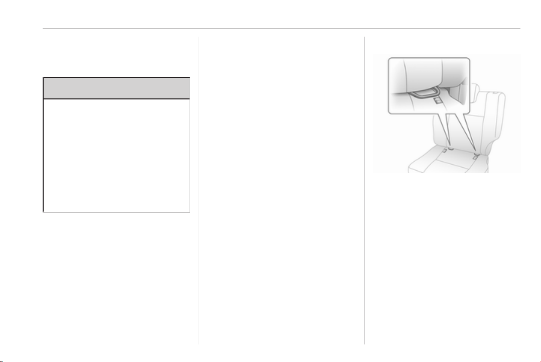
Top-Tether fastening eyes
Top-Tether fastening eyes are
located on the back of the seat.
In addition to the ISOFIX mounting,
fasten the Top-Tether strap to the
Top-Tether fastening eyes. The strap
must run between the two guide rods
of the head restraint.
ISOFIX child restraint systems of
universal category positions are
marked in the table by IUF 3 65.
Selecting the right system
The rear seats are the most
convenient location to fasten a child
restraint system.
Children should travel facing
rearwards in the vehicle as long as
possible. This makes sure that the
child's backbone, which is still very
weak, is under less strain in the event
of an accident.
Suitable are restraint systems that
comply with valid UN ECE
regulations. Check local laws and
regulations for mandatory use of child
restraint systems.
Ensure that the child restraint system
to be installed is compatible with the
vehicle type.
Ensure that the mounting location of
the child restraint system within the
vehicle is correct, see following
tables.
Allow children to enter and exit the
vehicle only on the side facing away
from the traffic.
When the child restraint system is not
in use, secure the seat with a seat belt
or remove it from the vehicle.
Note
Do not affix anything on the child
restraint systems and do not cover
them with any other materials.
A child restraint system which has
been subjected to stress in an
accident must be replaced.
Child locks 3 28.

Seats, restraints 65
Child restraint installation locations
Permissible options for fitting a child restraint system
Front seats - All variants
Weight and age class
Single seat - front passenger side
without airbag with airbag without airbag with airbag
Group 0: up to 10 kg
or approx. 10 months
Group 0+: up to 13 kg
U
2)
U
or approx. two years
Group I: 9 to 18 kg
U
2)
U
or approx. eight months to four years
Group II: 15 to 25 kg
or approx. three to seven years
Group III: 22 to 36 kg
U
2)
U
or approx. six to 12 years
1)
If adjustable, ensure seat is in its rearmost position. Make sure vehicle seat belt is as straight as possible between shoulder and
upper anchorage point.
2)
Ensure the front passenger airbag system is deactivated when installing a child restraint in this position.
1)
Bench seat - front passenger side
centre outer centre outer
U U
U U
U U
U
U
U
2)
2)
2)
2)
U
2)
U
2)
U

66 Seats, restraints
Doublecab - rear seats
Weight and age class 2nd row seats
Outer Centre
Group 0: up to 10 kg
or approx. 10 months
Group 0+: up to 13 kg
or approx. two years
Group I: 9 to 18 kg
or approx. eight months to four years
Group II: 15 to 25 kg
or approx. three to seven years
Group III: 22 to 36 kg
or approx. six to 12 years
U X
U X
U X

Seats, restraints 67
Combi - rear seats
Weight and age class 2nd row seats 3rd row seats
Driver side
outer seat Centre seat
Group 0: up to 10 kg
or approx. 10 months
Group 0+: up to 13 kg
U3), <
X X X
or approx. two years
Group I: 9 to 18 kg
or approx. eight months to four years
U4), < UF4), < UF
Group II: 15 to 25 kg
or approx. three to seven years
Group III: 22 to 36 kg
4)
U
UF
4)
or approx. six to 12 years
3)
Move the front seat as far forward as possible to install a rear facing child seat, then move back the seat in front in accordance with
the child seat instructions.
4)
Forward facing child seat; position the seatback of the child seat in contact with the seatback of the vehicle seat. Adjust the height
of the headrest or remove it if necessary; do not push the seat in front of the child more than halfway back on its runners and do not
recline the seatback more than 25°.
Passenger side
outer seat
4)
4)
UF
X
X

68 Seats, restraints
Bus - rear seats
Weight and age class Rear seats
Group 0: up to 10 kg
or approx. 10 months
Group 0+: up to 13 kg
or approx. two years
Group I: 9 to 18 kg
or approx. eight months to four years
Group II: 15 to 25 kg
or approx. three to seven years
Group III: 22 to 36 kg
or approx. six to 12 years
X
X
X

Seats, restraints 69
Crew cab - rear seats
Weight and age class 2nd row seats
Outer Centre
Group 0: up to 10 kg
or approx. 10 months
Group 0+: up to 13 kg
or approx. two years
Group I: 9 to 18 kg
or approx. eight months to four years
Group II: 15 to 25 kg
or approx. three to seven years
Group III: 22 to 36 kg
or approx. six to 12 years
U : suitable for universal category restraint systems for use in this weight and age class, in conjunction with three-point
seat belt.
UF : suitable for universal category forward-facing restraint systems for use in this weight and age class, in conjunction
with three-point seat belt.
: suitable for ISOFIX child restraint system with mounting brackets and anchorage points, where fitted. When mounting
<
an ISOFIX child restraint system, only systems that have been approved for the vehicle may be used. Refer to
"Permissible options for fitting an ISOFIX child restraint system".
X : seat position not suitable for children in this weight and age class.
U X
U X
U X

70 Seats, restraints
Permissible options for fitting an ISOFIX child restraint system
Combi
Weight class Size
Group 0: up to 10 kg
or approx. 10 months
Group 0+: up to 13 kg
or approx. two years
Group I: 9 to 18 kg
or approx. eight months to four years
IL : suitable for particular ISOFIX restraint systems of the "specific-vehicle", "restricted" or "semi-universal" categories.
The ISOFIX restraint system must be approved for the specific vehicle type.
IUF : suitable for ISOFIX forward-facing child restraint systems of universal category approved for use in this weight class.
X : no ISOFIX child restraint system approved in this weight class.
class
E ISO/R1 X IL X X X
E ISO/R1 X IL X X X
D ISO/R2 X IL X X X
C ISO/R3 X IL X X X
D ISO/R2 X IL X X X
C ISO/R3 X IL X X X
B ISO/F2 X IL, IUF IL, IUF X X
B1 ISO/F2X X IL, IUF IL, IUF X X
A ISO/F3 X IL, IUF IL, IUF X X
Fixture Front
seats
2nd row seats 3rd row
Driver side
outer seat
Centre
seat
Passenger side
outer seat
seats

Seats, restraints 71
ISOFIX size class and seat device
A - ISO/F3 : forward-facing child restraint system for children of maximum size in the weight class 9 to 18 kg.
B - ISO/F2 : forward-facing child restraint system for smaller children in the weight class 9 to 18 kg.
B1 - ISO/F2X : forward-facing child restraint system for smaller children in the weight class 9 to 18 kg.
C - ISO/R3 : rear-facing child restraint system for children of maximum size in the weight class up to 18 kg.
D - ISO/R2 : rear-facing child restraint system for smaller children in the weight class up to 18 kg.
E - ISO/R1 : rear-facing child restraint system for young children in the weight class up to 13 kg.

72 Storage
Storage
Storage compartments ................ 72
Instrument panel storage ........... 72
Glovebox ................................... 73
Cupholders ................................ 73
Front storage ............................. 73
Overhead console ..................... 74
Underseat storage ..................... 74
Overcab storage ........................ 75
Load compartment ....................... 75
Lashing eyes ............................. 75
Cargo management system ......76
Safety net .................................. 79
Load compartment grille ............ 79
Warning triangle ........................ 79
First aid kit ................................. 80
Fire extinguisher ........................ 80
Roof rack system ......................... 81
Roof rack ................................... 81
Loading information ..................... 81
Storage compartments
9 Warning
Do not store heavy or sharp
objects in the storage
compartments. Otherwise vehicle
occupants could be injured by
objects being thrown around in the
event of hard braking, a sudden
change in direction or an accident.
Instrument panel storage
Storage compartments, pockets and
trays are located in the instrument
panel.
A phone holder and/or a coin holder
with a clip for holding tickets is located
on the top of the instrument panel.
The tray located centrally on top of the
instrument panel has a lid.
Document holder
Withdraw the document holder from
the instrument panel by pulling the
base towards you and then swivelling
it downwards.
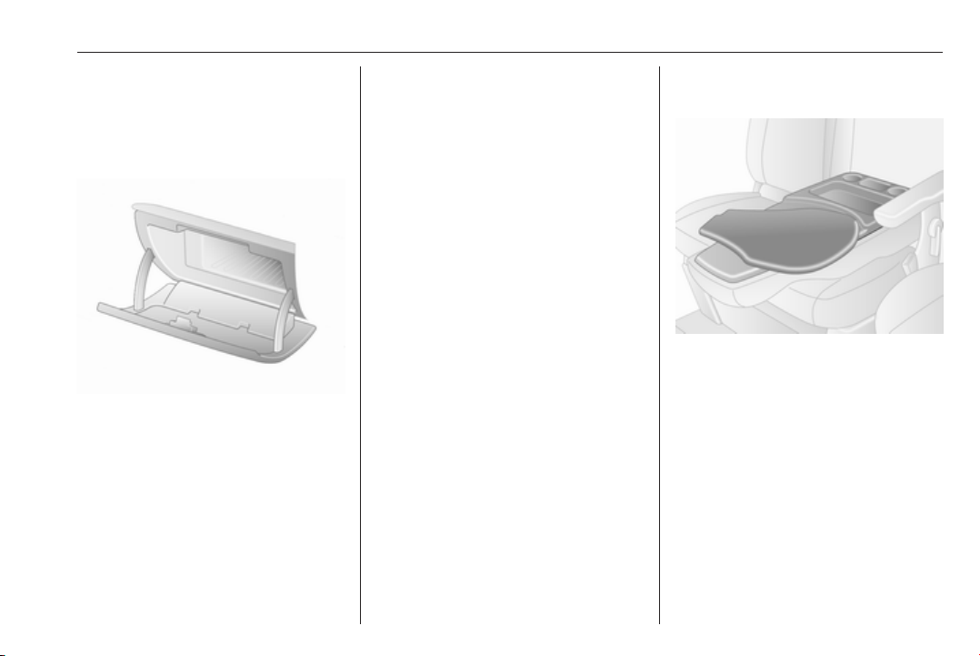
Storage 73
To fold away, raise the base until the
document holder is horizontal, then
push fully in.
Glovebox
The glovebox should be closed whilst
driving.
Glovebox cooler 3 130.
Cupholders
Cupholders are located at either end
of the instrument panel and centrally
in the lower instrument panel.
The cupholders can also be used to
hold the portable ashtray unit 3 89.
Additionally, cupholders may be
located in the rear side of the front
centre passenger seat. Folding
passenger seatback 3 73.
Depending on model, cupholders
may also be located in the lower front
part of the rear seats.
Front storage
Depending on model, coat hooks or
storage nets may be located on the
cabin bulkhead.
The front door pockets contain bottle
holders.
Folding front centre passenger seatback
Pull backrest release lever on the
front centre passenger seat towards
front of vehicle before folding down
the backrest to the horizontal
position.
The rear side of the backrest features
storage compartments, cupholders
and a swivelling shelf, which can be
used for writing or documents.
Return the swivelling shelf to its
original position before pulling
backrest release lever and raising the
backrest.
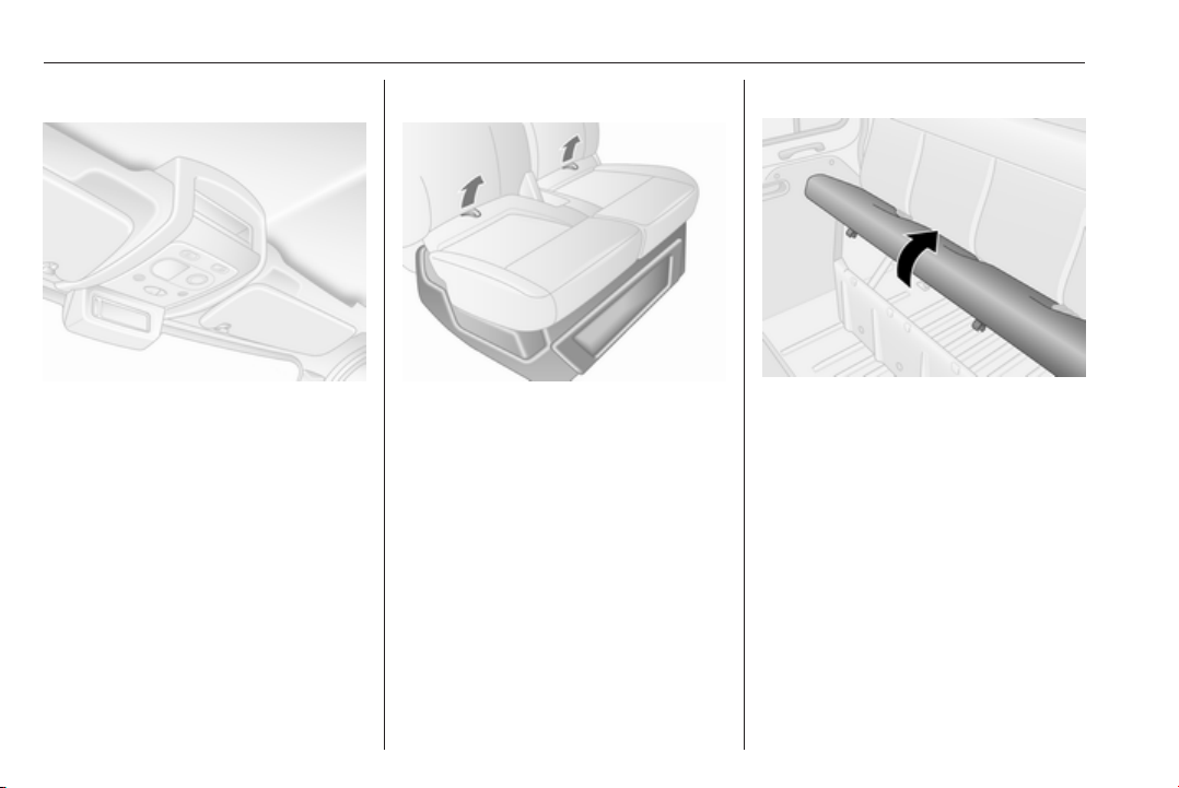
74 Storage
Overhead console
The total weight in these
compartments must not exceed 5 kg.
Underseat storage
Using the two loops on the passenger
seat cushion, pull the cushion
forwards to gain access to the storage
under the seat.
Rear bench seat
Raise seat base at front and remove
to gain access to storage
compartment under the bench seat.
Depending on model, bench seats
may also contain storage
compartments at the lower front part
of the seat and a storage net on the
outboard side of the seat.
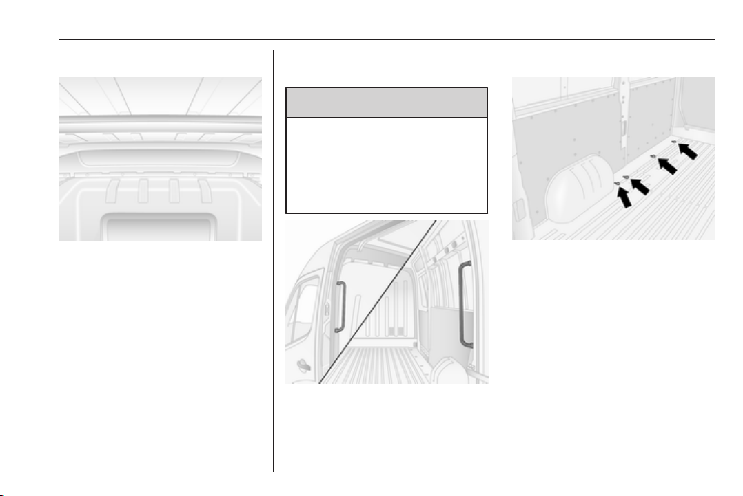
Storage 75
Overcab storage
The total weight in this compartment
must not exceed 35 kg.
Rear storage
Combi, Bus
Objects can be stored in the overhead
storage compartments above the rear
passenger seats.
The total weight must not exceed
20 kg evenly distributed.
Load compartment
9 Warning
Always make sure that the load in
the vehicle is securely stowed.
Otherwise objects can be thrown
around inside the vehicle and
cause personal injury or damage
to the load or vehicle.
Use the grab handles, located beside
the rear and sliding side door(s), to
assist during entry and exit of the load
compartment.
Lashing eyes
Lashing eyes are mounted in the load
compartment to enable cargo to be
secured in position using lashing
straps or a luggage floor net.
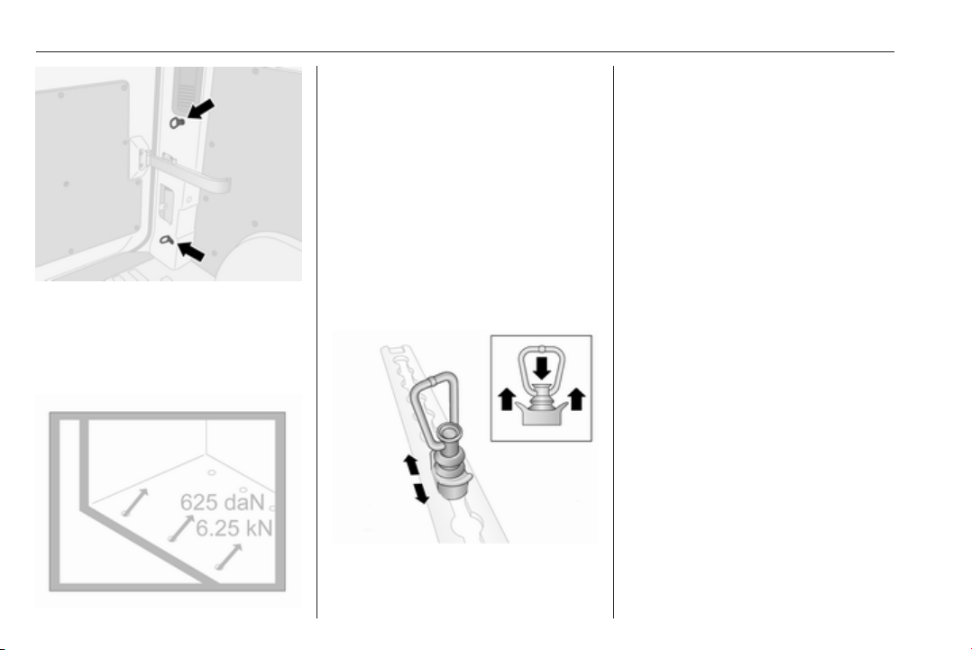
76 Storage
Lashing eyes may be located on the
vehicle floor and/or in the sidewall.
The number and location of the
lashing eyes may vary depending on
the vehicle.
The maximum force applied to the
lashing eyes should not exceed
625 daN/6.25 kN/6250 N.
Depending on country, the maximum
force (e.g. 500 daN/5 kN/5000 N) may
be shown on a label.
Note
Specifications on the label always
have priority over those given in this
manual.
Loading information 3 81.
Removable lashing eyes
The removable lashing eyes can be
secured to the side, floor or roof load
rails. Refer to "Cargo management
system" below for further information.
To reposition, press down on the
centre cap and slide to the desired
position. Ensure the lashing eyes
engage correctly in the recesses.
Loading information 3 81.
Cargo management system
Depending on vehicle, objects in the
load compartment can be secured
into position or prevented from sliding
excessively by attaching the
appropriate cargo management
feature to the side, floor or roof load
rails using removable lashing eyes (if
required).
Lower and also upper side load rails
may be present, depending on
version.
Moveable partition wall
The moveable partition wall can be
used between the floor and roof load
rails.
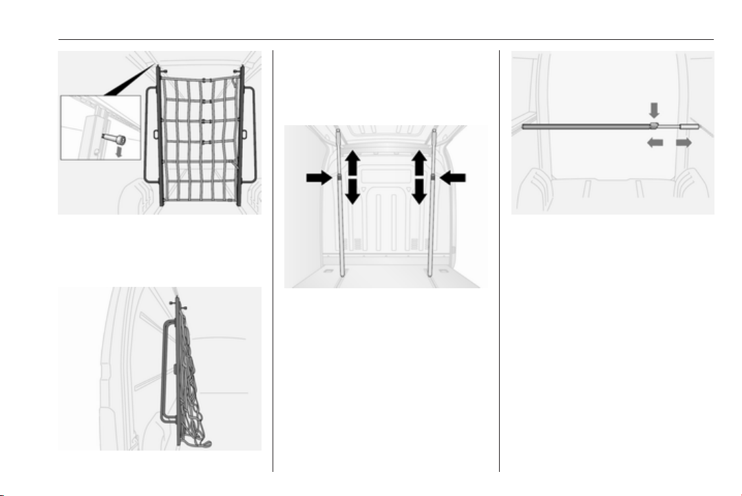
Store the partition wall to one side of
the load compartment when not in
use.
Telescopic blocking bars
Storage 77
To move, pull down on the latch to
release and position the wall as
required. Ensure the latch engages
fully and the partition wall is upright.
The telescopic blocking bars can be
used in a vertical position, secured to
the floor and roof load rails
or in a horizontal position, secured to
the side load rails.
Ensure the blocking bars are fully
engaged in the load rails before
loading the vehicle.
To release, press down on the lock
and slide the bar at the same time.
The maximum loading for the side
load rails is 100 daN/700 mm.
Blocking capacity: 300 kg.

78 Storage
Blocking bar with safety net
The blocking bar can be secured to
the upper side load rails; rotate
handle to fix blocking bar into
position. Ensure blocking bar
engages fully.
The integrated safety net can then be
attached to the removable lashing
eyes in the side and floor load rails
(see illustration).
Ratchet straps
Using the appropriate ratchet straps,
objects can be secured in position
using the removable lashing eyes in
the side or floor load rails.
The maximum loading for the floor
load rails is 500 daN/700 mm.
Lashing capacity: 800 daN in
strapping.
Steel fastener capacity: 170 daN in
direct tension.
The maximum loading for the side
load rails is 100 daN/700 mm.
Lashing capacity: 300 daN in
strapping.
Removable lashing eyes 3 75,
Loading information 3 81.

Storage 79
Safety net
Lower the safety net from the roof
area and attach to the lashing eyes in
the vehicle floor 3 75.
Adjust the tension on the straps to
ensure the load is secure.
When not in use the safety net should
be stored in the roof area.
Loading information 3 81.
Load compartment grille
Vehicles with a window in the cabin
bulkhead may include a metal grille
on the load compartment side.
The grille provides protection from
load compartment objects being
thrown around in the event of hard
braking, a sudden change in direction
or an accident.
Depending on version, the windows
in the rear door and sliding side
door(s) also contain window guards,
for additional protection and security.
Loading information 3 81.
Warning triangle
The warning triangle can be
accommodated in the space under
the front seats.
Underseat storage 3 74.
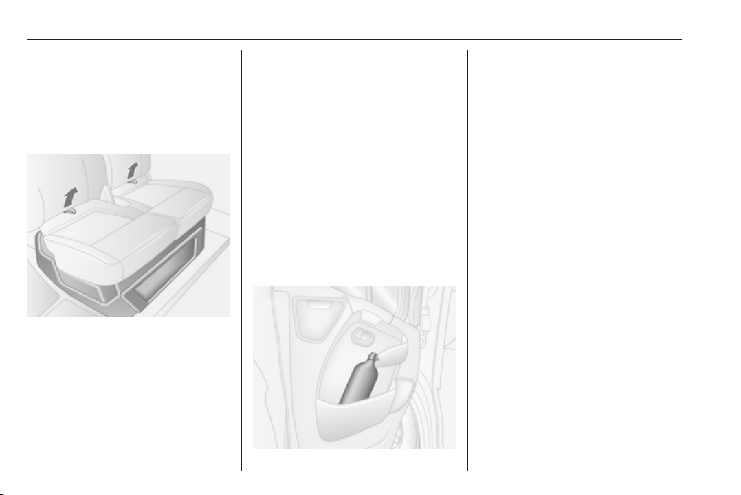
80 Storage
First aid kit
As a visible indication of the presence
of a first aid kit, a label may be located
on the overhead console 3 74.
The first aid kit can be accommodated
in the space under the front seats.
Using the two loops on the seat
cushion, pull the cushion forwards to
gain access.
Underseat storage 3 74.
Depending on version, the first aid kit
may alternatively be located in the
space between the front seats or in
the overhead console.
Fire extinguisher
As a visible indication of the presence
of a fire extinguisher, a label may be
located on the overhead console
3 74.
The fire extinguisher can be
accommodated in the space under
the front seats. Using the two loops on
the seat cushion, pull the cushion
forwards to gain access.
Underseat storage 3 74.
Depending on version, the fire
extinguisher may alternatively be
located in the space between the front
seats.
An additional fire extinguisher may be
located in the front door panel or in the
load compartment.

Storage 81
Roof rack system
Roof rack
For safety reasons and to avoid
damage to the roof, the vehicle
approved roof rack system is
recommended.
Follow the installation instructions
and remove the roof rack when not in
use.
Loading information
● Heavy objects in the load
compartment should be evenly
distributed and placed as far
forward as possible. If objects
can be stacked, the heavier
objects should be placed at the
bottom.
● Secure objects with lashing
straps attached to lashing eyes
3 75.
● Secure objects into position or
prevent loads from sliding
excessively by attaching optional
cargo management features to
the load rails using removable
lashing eyes. Cargo
management system 3 76.
● Secure loose objects in load
compartment to prevent them
from sliding.
● The load must not obstruct the
operation of the pedals, parking
brake and gear selector lever, or
hinder the freedom of movement
of the driver. Do not place any
unsecured objects in the interior.
● Do not drive with an open load
compartment. In addition, the
number plate is only
distinguishable and illuminated
correctly if the doors are closed.
9 Warning
Always make sure that the load in
the vehicle is securely stowed.
Otherwise objects can be thrown
around inside the vehicle and
cause personal injury or damage
to the load or vehicle.
● The payload is the difference
between the permitted gross
vehicle weight (see identification
plate 3 225) and the EC kerb
weight.
To calculate the payload, enter
the data for your vehicle in the
Weights table at the front of this
manual.
The EC kerb weight includes
weights for the driver (68 kg),
luggage (7 kg) and all fluids (fuel
tank 90% full).

82 Storage
Optional equipment and
accessories increase the kerb
weight.
● Driving with a roof load increases
the sensitivity of the vehicle to
cross-winds and has a
detrimental effect on vehicle
handling due to the vehicle's
higher centre of gravity.
Distribute the load evenly and
secure it properly with retaining
straps. Adjust the tyre pressure
and vehicle speed according to
the load conditions. Check and
retighten the straps frequently.
Do not drive faster than
120 km/h.
● The permissible roof load (which
includes the weight of the roof
rack) is 200 kg for standard roof
variants. The roof load is the
combined weight of the roof rack
and the load.

Instruments and controls 83
Instruments and controls
Controls ....................................... 84
Steering wheel adjustment ........ 84
Steering wheel controls ............. 84
Horn ........................................... 84
Steering column controls ........... 84
Windscreen wiper/washer ......... 85
Outside temperature .................. 86
Clock ......................................... 87
Power outlets ............................. 87
Cigarette lighter ......................... 89
Ashtrays .................................... 89
Warning lights, gauges and indi‐
cators ........................................... 89
Instrument cluster ...................... 89
Speedometer ............................. 89
Odometer .................................. 90
Trip odometer ............................ 90
Tachometer ............................... 90
Fuel gauge ................................ 91
AdBlue gauge ............................ 91
Engine coolant temperature
gauge ....................................... 91
Engine oil level monitor ............. 92
Service display .......................... 92
Transmission display ................. 93
Control indicators ...................... 93
Turn signal ................................. 96
Seat belt reminder ..................... 96
Airbag and belt tensioners ......... 96
Airbag deactivation .................... 96
Charging system ....................... 97
Malfunction indicator light .......... 97
Service vehicle soon ................. 97
Stop engine ............................... 98
Brake system ............................. 98
Antilock brake system (ABS) ..... 98
Upshift ....................................... 98
Lane departure warning ............ 98
Electronic Stability Program ......99
Electronic Stability Program
off ............................................. 99
Engine coolant temperature ......99
Preheating ................................. 99
AdBlue ....................................... 99
Tyre pressure monitoring
system ...................................... 99
Engine oil pressure .................. 100
Low fuel ................................... 100
Stop-start system .................... 100
Exterior light ............................ 101
High beam ............................... 101
High beam assist ..................... 101
Fog light ................................... 101
Rear fog light ........................... 101
Cruise control .......................... 101
Tachograph ............................. 101
Door open ................................ 101
Information displays ................... 102
Driver Information Centre ........ 102
Info display .............................. 102
Vehicle messages ...................... 103
Warning chimes ....................... 103
Trip computer ............................. 104
Tachograph ................................ 106
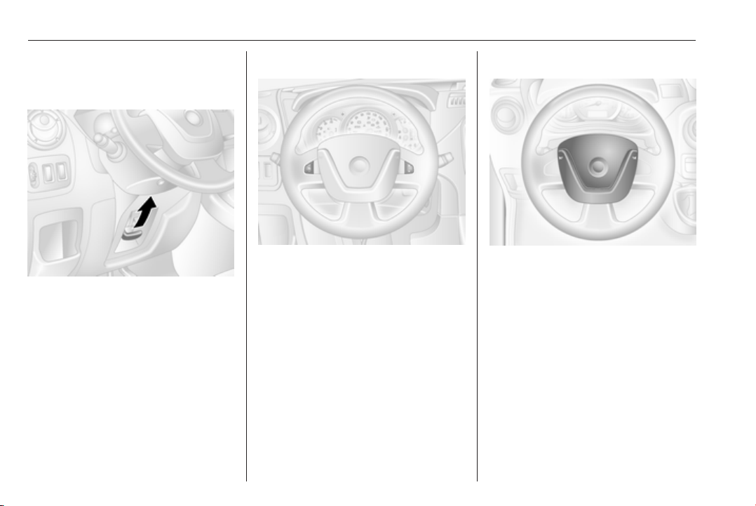
84 Instruments and controls
Controls
Steering wheel adjustment
Unlock lever, adjust steering wheel,
then engage lever and ensure it is
fully locked.
Do not adjust steering wheel unless
vehicle is stationary and steering
wheel lock has been released.
Steering wheel controls
The cruise control and speed limiter
can be operated via the controls on
the steering wheel.
Cruise control and speed limiter
3 159.
Horn
Press j.
The horn will sound regardless of
ignition switch position.
Steering column controls
The Infotainment system can also be
operated via the controls on the
steering column.
Further information is available in the
Infotainment manual.

Instruments and controls 85
Windscreen wiper/washer
Windscreen wiper
0 : off
P/AUTO : timed interval wiping or
automatic wiping with
rain sensor
1 : slow
2 : fast
Do not use if the windscreen is frozen.
Switch off in car washes.
Note
During driving, wiper speed is
reduced automatically when the
vehicle is at a standstill. As soon as
the vehicle starts to move, wiping
returns to the selected speed unless
the lever has been moved.
Adjustable delay of timed interval wiping
P/AUTO : timed interval wiping
Turn the adjuster wheel to adjust the
delay between wipes:
longer delay : turn adjuster
wheel downwards
shorter delay : turn adjuster
wheel upwards
Timed interval wiping will need to be
reselected whenever the ignition has
been switched off.
Automatic wiping with rain sensor P/AUTO : automatic wiping with
rain sensor
The rain sensor detects the amount of
water on the windscreen and
automatically regulates the frequency
of the windscreen wipers.
Automatic wiping will need to be
reselected whenever the ignition has
been switched off.
Note
During extreme weather conditions,
e.g. fog or snow, automatic wiping
with rain sensor may become
unavailable. If required, select
another wiper position.

86 Instruments and controls
Adjustable sensitivity of the rain sensor
Turn the adjuster wheel to adjust the
sensitivity:
low sensitivity : turn adjuster
wheel downwards
high sensitivity : turn adjuster
wheel upwards
Pull lever. Washer fluid is sprayed
onto the windscreen.
short pull : wiper swipes once
long pull : wiper swipes for a few
strokes
Outside temperature
Keep the sensor free from dust, dirt
and ice.
Windscreen washer
A drop in temperature is indicated
immediately and a rise in temperature
after a time delay.
If outside temperatures drop to 3 °C,
the °C flashes in the information
display as a warning for icy road
conditions. This will continue to flash
until temperatures rise above 3 °C.
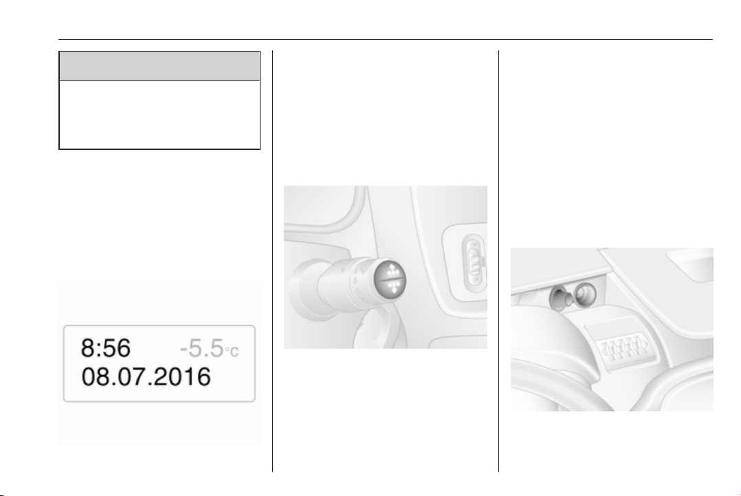
Instruments and controls 87
9 Warning
The road surface may already be
icy even though the display
indicates a few degrees above
0 °C.
Clock
Depending on vehicle, the current
time and/or date may appear in the
information display 3 102 or the
Driver Information Centre 3 102.
Set time and date in information display
Hours and minutes can be adjusted
by pressing the appropriate buttons
by the display or with the Infotainment
system controls.
Further information is available in the
Infotainment manual.
Set time in Driver Information Centre
Display the clock function by pressing
button repeatedly on end of wiper
lever. When the time flashes (after
approx. two seconds):
● Press and hold the bottom
button.
● Hours flash.
● Press top button to change
hours.
● Press and hold bottom button to
set hours.
● Minutes flash.
● Press top button to change
minutes.
● Press and hold bottom button to
set minutes and exit setting
mode.
Power outlets
12 V power outlets are located on top
of the instrument panel, or beside the
gearshift lever.
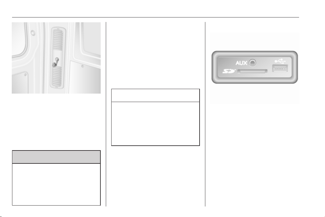
88 Instruments and controls
Depending on vehicle, an additional
outlet may be located in the rear of the
vehicle.
Connecting electrical accessories
while the engine is off will discharge
the vehicle battery. Do not exceed the
maximum power consumption of
120 watts.
9 Danger
To avoid the risk of fire, if multiple
power outlets are used
simultaneously, the total power
consumption of connected
accessories must not exceed
180 watts.
With ignition off the power outlet may
be deactivated.
Additionally, the power outlet may be
deactivated in case of low battery
voltage.
Electrical accessories that are
connected must comply with the
electromagnetic compatibility
requirements laid down in
DIN VDE 40 839.
Caution
Do not connect any currentdelivering accessories, e.g.
electrical charging devices or
batteries.
Do not damage the outlets by
using unsuitable plugs.
USB socket
In the Infotainment unit (or on the
instrument panel) there is a USB
socket M for the connection of external
audio sources and for charging
devices.
Note
The sockets must always be kept
clean and dry.
AUX socket, SD card slot - refer to the
Infotainment manual.

Instruments and controls 89
Cigarette lighter
Press in cigarette lighter. It switches
off automatically once the element is
glowing. Pull out lighter.
Ashtrays
Caution
To be used only for ash and not for
combustible rubbish.
Portable ashtray
Ashtray container for mobile use in
the vehicle. To use, open cover.
Warning lights, gauges and indicators
Instrument cluster
In some versions, the needles of the
instruments briefly rotate to the end
position when the ignition is switched
on.
Speedometer
Indicates vehicle speed.
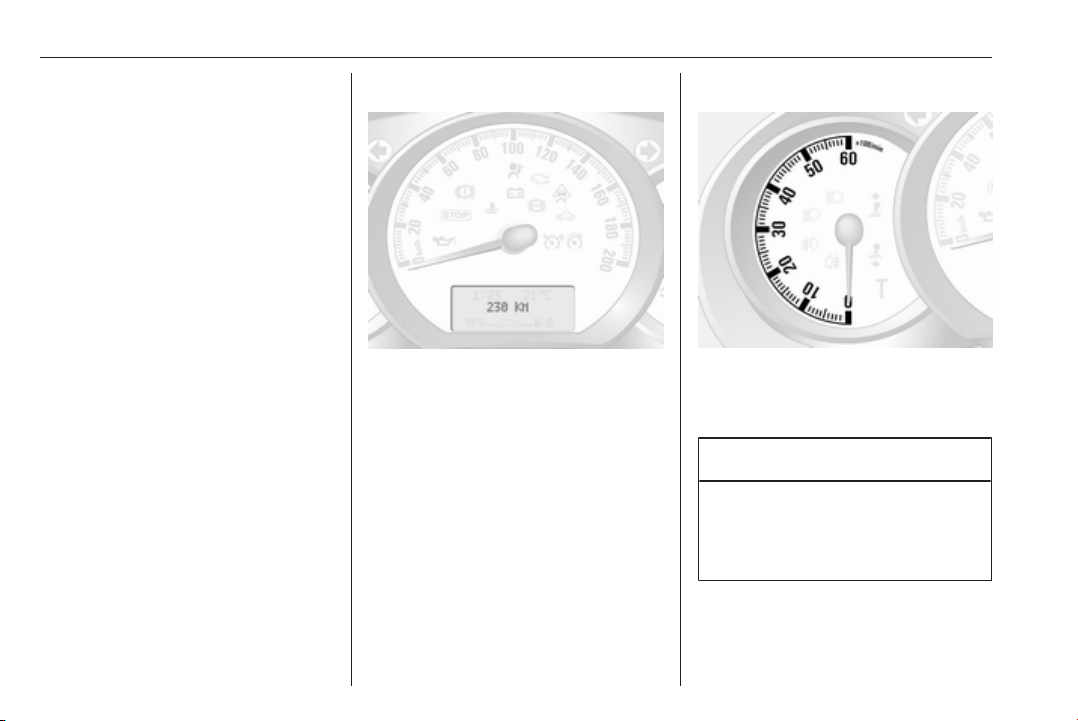
90 Instruments and controls
Speed limiter
Maximum speed may be restricted by
a speed limiter. As a visible indication
of this, a warning label is located on
the instrument panel.
A warning buzzer will sound for
ten seconds if the vehicle briefly
exceeds the set limit.
Note
Under certain conditions (e.g. steep
inclines) the vehicle speed may
exceed the set limit.
Speed limiter 3 163, cruise control
speed limiter 3 159.
Odometer
Displays the recorded distance in km.
Trip odometer
The trip odometer displays the
distance travelled since the last reset.
Press button once on end of
windscreen wiper lever to display the
trip odometer.
To reset, with the trip odometer
displayed, press and hold button for a
few seconds with the ignition on. The
display will flash and the value will
reset to zero.
Tachograph 3 106.
Tachometer
Displays the engine speed.
Drive in a low engine speed range for
each gear as much as possible.
Caution
If the needle is in the red warning
zone, the maximum permitted
engine speed is exceeded. Engine
at risk.
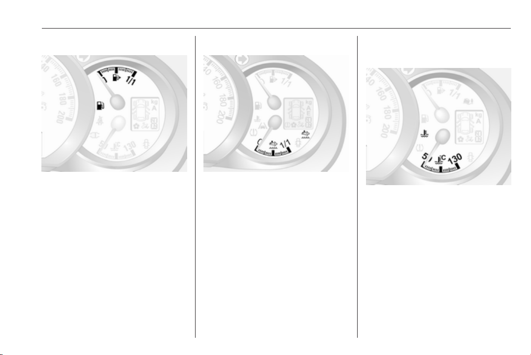
Instruments and controls 91
Fuel gauge
Displays fuel level in the tank.
Control indicator Y illuminates if the
level in the tank is low. Refuel
immediately 3 169.
Never run the tank dry. Diesel fuel
system, bleeding 3 183.
Because of the fuel remaining in the
tank, the top-up quantity may be less
than the specified tank capacity.
AdBlue gauge
In versions without AdBlue level
warnings in the Driver Information
Centre, an AdBlue gauge is present,
which shows the current AdBlue fluid
level remaining in the tank.
Control indicator Y 3 99 illuminates
if the level in the tank is low. Refill
AdBlue as soon as possible to avoid
prevention of engine starts.
AdBlue 3 143.
Engine coolant temperature gauge
Displays the coolant temperature.
left area : engine operating
temperature not yet
reached
central
area
right area : temperature too high
Control indicator W illuminates if the
temperature is too high 3 98,
3 99.
: normal operating
temperature

92 Instruments and controls
Caution
If engine coolant temperature is
too high, stop vehicle, switch off
engine. Danger to engine. Check
coolant level.
For physical reasons, the coolant
temperature gauge shows the coolant
temperature only if the coolant level is
adequate.
Engine oil level monitor
The engine oil level monitor is correct
only if the vehicle is parked on a level
surface with a cold engine.
If the engine oil level is correct when
the ignition is switched on OIL LEVEL
CORRECT appears briefly in the
Driver Information Centre.
If the engine oil is above the minimum
level, press the trip computer button
on the end of the wiper lever within
30 seconds of switching on the
ignition. The message OIL LEVEL is
displayed in combination with the
squares that correspond to the oil
level.
As the oil level diminishes, the
squares in the display are replaced
with dashes.
▢▢▢▢▢▢ : maximum level
▢▢▢- - - : intermediate level
- - - - - - : minimum level
If the minimum engine oil level is
reached TOP-UP OIL LEVEL is
displayed in combination with control
indicator A after the ignition is
switched on for 30 seconds. Check
and top up engine oil 3 177.
To exit the oil level monitor display,
press either trip computer button.
Trip computer 3 104.
Service display
When the ignition is switched on, the
remaining distance before the next
service is due may be shown briefly in
the Driver Information Centre. Based
on driving conditions, the interval at
which a service will be indicated can
vary considerably.
When the remaining distance before
the next service is less than
3000 km or two months, SERVICE
IN appears in the Driver Information
Centre.
When the distance reaches 0 km or
the service date is due, control
indicators o and A illuminate in the
instrument cluster and SERVICE
DUE appears in the Driver
Information Centre.
The vehicle needs a service. Seek the
assistance of a workshop.
Resetting the service display
After a service, the service display
must be reset: if available, select the
distance before service display in the
Driver Information Centre, then press
and hold button on end of wiper lever
for approx. ten seconds until the
distance before service is displayed
continuously.
Trip computer 3 104.
Driver Information Centre 3 102.
Service information 3 220.

Instruments and controls 93
Transmission display
The mode or selected gear of the
manual transmission automated is
shown in the transmission display.
R : reverse gear
N : neutral
A : automatic mode
kg : laden mode
: winter mode
V
: apply footbrake
T
: transmission electronics
W
Manual transmission automated
3 150.
Control indicators
The control indicators described are
not present in all vehicles. The
description applies to all instrument
versions. Depending on the
equipment, the position of the control
indicators may vary. When the
ignition is switched on, most control
indicators will illuminate briefly as a
functionality test.
The control indicator colours mean:
red : danger, important reminder
yellow : warning, information, fault
green : confirmation of activation
blue : confirmation of activation
white : confirmation of activation

94 Instruments and controls
Control indicators in the instrument cluster

Instruments and controls 95
Control indicators in the instrument panel
Control indicators in the roof console
Overview
Turn signal 3 96
O
Seat belt reminder 3 96
X
Airbag and belt tensioners
v
3 96
W
Airbag deactivation 3 96
Charging system 3 97
p
Malfunction indicator light
Z
3 97
Service vehicle soon 3 97
A
o
Service display 3 97
C
Stop engine 3 98
Brake system 3 98
R
Antilock brake system (ABS)
u
3 98
kj
Upshift, downshift 3 98
ì
Lane departure warning 3 98
R
Electronic Stability Program
3 99
Ø
Electronic Stability Program off
3 99
Engine coolant temperature
W
3 99
Preheating 3 99
!
Y
AdBlue 3 99
Tyre pressure monitoring
w
system 3 99
Engine oil pressure 3 100
I
Low fuel 3 100
Y
D
Autostop (Stop-start system)
3 100
\
Autostop inhibited (Stop-start
system) 3 100
Exterior light 3 101
9
High beam 3 101
C
í
High beam assist 3 101
Fog light 3 101
>
ø
Rear fog light 3 101
m
Cruise control 3 101
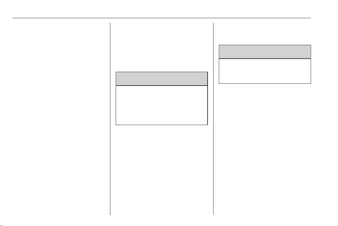
96 Instruments and controls
Cruise control speed limiter
U
3 101
Tachograph 3 101
&
Door open 3 101
y
Turn signal
O flashes green.
Flashes if a turn signal or the hazard
warning flashers are activated.
Rapid flashing: failure of a turn signal
light or associated fuse.
An audible warning can be heard
when the turn signals are on. When
towing a trailer, the pitch of the
audible warning changes.
Bulb replacement 3 185.
Fuses 3 194.
Turn signals 3 111.
Seat belt reminder
X illuminates or flashes red.
If the seat belt is unfastened, control
indicator X will flash when vehicle
speed exceeds approx. 16 km/h. A
warning chime also sounds for
approx. 90 seconds.
If the seat belt is fastened, the
indicator light extinguishes.
9 Warning
Fasten seat belt before each trip.
In the event of an accident, people
not wearing seat belts endanger
their fellow occupants and
themselves.
Three-point seat belts 3 54.
Airbag and belt tensioners
v illuminates yellow.
When the ignition is switched on, the
control indicator illuminates briefly. If
it does not illuminate or illuminates
whilst driving, there is a fault in the
airbag system. Seek the assistance
of a workshop. The airbags and belt
pretensioners may fail to trigger in the
event of an accident.
Deployment of the belt pretensioners
or airbags is indicated by continuous
illumination of v.
9 Warning
Have the cause of the fault
remedied immediately by a
workshop.
Belt pretensioners, airbag system
3 53, 3 57.
Airbag deactivation
W illuminates yellow when the
ignition is switched on and remains
illuminated when the front passenger
airbag has been deactivated 3 61.

Instruments and controls 97
9 Danger
Risk of fatal injury for a child using
a child restraint system together
with activated front passenger
airbag.
Risk of fatal injury for an adult
person with deactivated front
passenger airbag.
Airbag system 3 57, belt tensioners
3 53, airbag deactivation 3 61.
Charging system
p illuminates red.
Illuminates when the ignition is
switched on and extinguishes shortly
after the engine starts.
Illuminates when the engine is running
Stop, switch off engine. Vehicle
battery is not charging. Engine
cooling may be interrupted. The
brake servo unit may cease to be
effective. Seek the assistance of a
workshop.
Malfunction indicator light
Z illuminates or flashes yellow.
Illuminates briefly when the ignition is
switched on.
Illuminates when the engine is running
Fault in the emission control system.
The permitted emission limits may be
exceeded. Seek the assistance of a
workshop immediately.
If Z illuminates in combination with
A, stop vehicle and switch off engine
as soon as possible.
9 Warning
Have the cause of the fault
remedied immediately by a
workshop.
Flashes when the engine is running
Fault that could lead to catalytic
converter damage. Ease up on the
accelerator until the flashing stops.
Seek the immediate assistance of a
workshop.
Service vehicle soon
A illuminates yellow.
Illuminates briefly when the ignition is
switched on.
The vehicle needs a service.
May illuminate in combination with
another control indicator or a
message in the Driver Information
Centre 3 102.
Illuminates if cleaning of the diesel
particle filter is required and
automatic cleaning does not occur
3 142.
9 Warning
Have the cause of the fault
remedied immediately by a
workshop.
Service display
Control indicator o also illuminates in
the Driver Information Centre when
the remaining distance before the
next service reaches 0 km or the
service date is due.

98 Instruments and controls
The message SERVICE DUE also
appears in the Driver Information
Centre.
Service display 3 92.
Stop engine
C illuminates red.
Illuminates briefly when the ignition is
switched on.
If C illuminates (possibly in
combination with W and/or R), stop
vehicle and switch off engine as soon
as possible.
9 Warning
Have the cause of the fault
remedied immediately by a
workshop.
Depending on the type of fault, a
warning message may also appear in
the Driver Information Centre 3 102.
Brake system
R illuminates red.
Control indicator R remains
illuminated after the ignition is
switched on if the parking brake is
applied and extinguishes when the
parking brake is released 3 155.
When the parking brake is released,
R illuminates (possibly in
combination with C) if the brake fluid
level is too low 3 180.
9 Warning
Stop. Do not continue your
journey. Consult a workshop.
Brake system 3 154.
Antilock brake system (ABS)
u illuminates yellow.
Illuminates briefly when the ignition is
switched on. The system is ready for
operation when u extinguishes.
If control indicators u and A
illuminate with the messages CHECK
ABS and CHECK ESP in the Driver
Information Centre 3 102, there is a
fault in the ABS. The brake system
remains operational but without ABS
regulation.
If control indicators u, A, R and
C illuminate, the ABS and ESP are
deactivated and the message
BRAKING FAULT is displayed. Seek
the assistance of a workshop.
Antilock brake system 3 154.
Upshift
k or j illuminates yellow.
Illuminates when gearshifting is
recommended for fuel saving
reasons.
ECO mode 3 133.
Lane departure warning
ì illuminates white.
Illuminates briefly when the ignition is
switched on and the system is ready
to operate.
A warning chime sounds in
conjunction with ì when the system
recognises an unintended lane
change.
 Loading...