

Page 1
Chapter 1
Routine maintenance and servicing
Air cleaner filter element renewal . . . . . . . . . . . . . . . . . . . . . . . . . . . .24
Automatic transmission fluid level check . . . . . . . . . . . . . . . . . . . . . .13
Automatic transmission fluid renewal . . . . . . . . . . . . . . . . . . . . . . . . .33
Auxiliary drivebelt check and renewal . . . . . . . . . . . . . . . . . . . . . . . . .9
Battery check . . . . . . . . . . . . . . . . . . . . . . . . . . . . . . . . . . . . . . . . . . . .4
Brake fluid renewal . . . . . . . . . . . . . . . . . . . . . . . . . . . . . . . . . . . . . . .30
Brake pad, caliper and disc check . . . . . . . . . . . . . . . . . . . . . . . . . . .17
Carburettor fuel inlet filter cleaning . . . . . . . . . . . . . . . . . . . . . . . . . . .26
Clutch adjustment check . . . . . . . . . . . . . . . . . . . . . . . . . . . . . . . . . .28
Coolant renewal . . . . . . . . . . . . . . . . . . . . . . . . . . . . . . . . . . . . . . . . .32
Driveshaft CV joint and gaiter check . . . . . . . . . . . . . . . . . . . . . . . . .20
Electrical system check . . . . . . . . . . . . . . . . . . . . . . . . . . . . . . . . . . .14
Engine oil and filter renewal . . . . . . . . . . . . . . . . . . . . . . . . . . . . . . . . .6
Exhaust system check . . . . . . . . . . . . . . . . . . . . . . . . . . . . . . . . . . . .22
Fluid level checks . . . . . . . . . . . . . . . . . . . . . . . . . . . . . . . . . . . . . . . . .3
Fuel filter renewal - fuel injection models . . . . . . . . . . . . . . . . . . . . . .25
Fuel pump filter cleaning - carburettor models . . . . . . . . . . . . . . . . .12
Handbrake adjustment . . . . . . . . . . . . . . . . . . . . . . . . . . . . . . . . . . . .19
Headlamp aim check . . . . . . . . . . . . . . . . . . . . . . . . . . . . . . . . . . . . .31
Hinge and lock lubrication . . . . . . . . . . . . . . . . . . . . . . . . . . . . . . . . .21
Hose and fluid leak check . . . . . . . . . . . . . . . . . . . . . . . . . . . . . . . . . .8
Idle speed and mixture adjustments . . . . . . . . . . . . . . . . . . . . . . . . .11
Ignition system check . . . . . . . . . . . . . . . . . . . . . . . . . . . . . . . . . . . . . .9
Introduction . . . . . . . . . . . . . . . . . . . . . . . . . . . . . . . . . . . . . . . . . . . . .2
Manual transmission oil level check . . . . . . . . . . . . . . . . . . . . . . . . . .27
Rear brake shoe, wheel cylinder and drum check . . . . . . . . . . . . . . .29
Rear wheel bearing adjustment . . . . . . . . . . . . . . . . . . . . . . . . . . . . .18
Road test . . . . . . . . . . . . . . . . . . . . . . . . . . . . . . . . . . . . . . . . . . . . . .23
Roadwheel bolt tightness check . . . . . . . . . . . . . . . . . . . . . . . . . . . .16
Spark plug renewal . . . . . . . . . . . . . . . . . . . . . . . . . . . . . . . . . . . . . . . .7
Tyre checks . . . . . . . . . . . . . . . . . . . . . . . . . . . . . . . . . . . . . . . . . . . . .5
Vauxhall Astra/Belmont maintenance schedule . . . . . . . . . . . . . . . . . .1
Wiper blade check . . . . . . . . . . . . . . . . . . . . . . . . . . . . . . . . . . . . . . .15
The maintenance intervals in this manual are provided with the
assumption that you, not the dealer, will be carrying out the work.
These are the minimum maintenance intervals recommended by the
manufacturer for vehicles driven daily. If you wish to keep your vehicle
in peak condition at all times, you may wish to perform some of these
procedures more often. We encourage frequent maintenance, because
it enhances the efficiency, performance and resale value of your
vehicle. If the vehicle is driven in dusty areas, used to tow a trailer, or
driven frequently at slow speeds (idling in traffic) or on short journeys,
more frequent maintenance intervals are recommended.
When the vehicle is new, it should be serviced by a factoryauthorised dealer service department, in order to preserve the factory
warranty.
1•1
Easy, suitable for
novice with little
experience
Fairly easy, suitable
for beginner with
some experience
Fairly difficult, suitable
for competent DIY
mechanic
Difficult, suitable for
experienced DIY
mechanic
Very difficult,
suitable for expert DIY
or professional
Degrees of difficulty
Contents
1
1 Vauxhall Astra/Belmont maintenance schedule
Page 2

1•2 Maintenance schedule
Every 9000 miles (15 000 km) or
6 months, whichever comes first
mm Renew the engine oil and filter - early (pre-1987) models
(Section 6)
Every 9000 miles (15 000 km) or
12 months, whichever comes first
mm Renew the engine oil and filter - later (1987-on) models
(Section 6)
mm Renew the spark plugs (Section 7)
mm Check and adjust the valve clearances - 1.2 litre models
(Chapter 2A)
mm Check all underbonnet and underbody components, pipes and
hoses for leaks (Section 8)
mm Check the condition of the auxiliary drivebelt, and renew if
necessary (Section 9)
mm Check the ignition system components and renew the contact
breaker points (Section 10)
mm Check idle speed and mixture adjustments (Section 11)
mm Clean the fuel pump filter (carburettor models) (Section 12)
mm Check the throttle cable adjustment (Chapter 4A or 4B)
mm Check the automatic transmission fluid level (Section 13)
mm Check the operation of the horn, all lights, and the wipers and
washers (Section 14)
mm Check the condition of the wiper blades (Section 15)
mm Check the tightness of the roadwheel bolts (Section 16)
mm Check the condition of the front, and rear (where fitted) brake
pads (renew if necessary), and the calipers and discs
(Section 17)
mm Check the rear wheel bearings adjustment (Section 18)
mm Check the handbrake adjustment (Section 19)
mm Check the driveshaft CV joints and gaiters for condition
(Section 20)
mm Lubricate locks and hinges (Section 21)
mm Check the exhaust system for condition and security
(Section 22)
mm Road test the vehicle (Section 23)
Every 2 years
(regardless of mileage)
In addition to all the relevant items listed previously, carry out the
following:
mm Renew the coolant (Section 32)
Every 36 000 miles (60 000 km) or
4 years, whichever comes first
In addition to all the relevant items listed previously, carry out the
following:
mm Renew the automatic transmission fluid (Section 33)
mm Renew the camshaft toothed belt -
1.3, 1.4, 1.6, 1.8 and 2.0 litre 8-valve engines (Chapter 2B),
2.0 litre 16-valve engines (Chapter 2C)
Every 54 000 miles (90 000 km) or
3 years, whichever comes first
In addition to all the relevant items listed previously, carry out the
following:
mm Renew the braking system seals and hose (Chapter 9)
Every 18 000 miles (30 000 km) or
12 months, whichever comes first
In addition to all the items listed previously, carry out the following:
mm Renew the air cleaner filter element (Section 24)
mm Renew the fuel filter (fuel injection models) (Section 25)
mm Clean the carburettor fuel inlet filter (Section 26)
mm Check the manual transmission oil level (Section 27)
mm Check the clutch adjustment (Section 28)
mm Check the condition of the rear brake shoes (renew if
necessary), wheel cylinders and drums (Section 29)
mm Renew the brake fluid (Section 30)
mm Check the headlamp alignment (Section 31)
Every 250 miles (400 km) or weekly
mm See Weekly checks
Page 3
Maintenance - component location 1•3
1
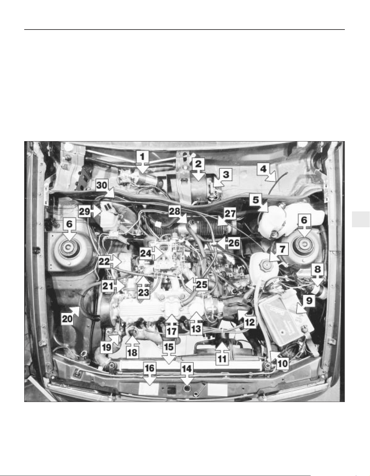
1 Wiper motor
2 Heater blower motor
3 Heater blower motor resistor
4 Windscreen washer tube
5 Screen washer reservoir
6 Suspension turrets
7 Coolant expansion tank
8 Ignition coil
9 Battery
10 Coolant hose
11 Radiator cooling fan
12 Distributor cover
13 Engine oil filler
14 Bonnet catch
15 Radiator
16 VIN plate
17 Engine breather
18 Air cleaner hot air pick-up
19 Thermostat housing
20 Fuel hoses
21 Fuel pump
22 Alternator
23 Accelerator cable
24 Carburettor
25 Choke cable
26 Servo non-return valve
27 Steering rack bellows
28 Air cleaner breather hose
29 Brake fluid reservoir
30 Brake servo
Underbonnet view of an early 1.6 litre model (air cleaner removed for clarity)
Page 4
1•4 Maintenance - component location
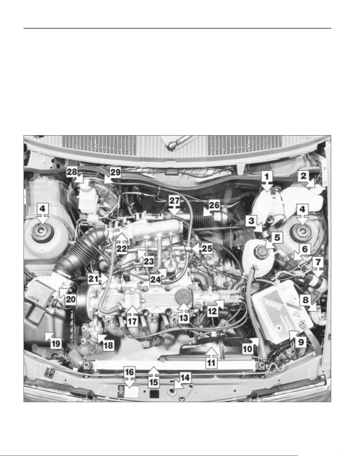
1 Screen washer reservoir
2 Headlamp washer filler cap
3 Headlamp washer relay and fuse
4 Suspension turrets
5 Coolant expansion tank filler
6 Control relay (fuel injection system)
7 Ignition coil
8 Horn
9 Battery
10 Coolant hose
11 Radiator fan
12 Distributor
13 Engine oil filler
14 Bonnet catch
15 Radiator
16 VIN plate
17 Engine breather
18 Thermostat housing
19 Air cleaner
20 Airflow meter
21 Breather hose
22 Throttle valve housing
23 Fuel rail
24 Fuel pressure regulator
25 Servo non return valve
26 Steering rack bellows
27 Accelerator cable
28 Brake fluid reservoir
29 Brake servo
Underbonnet view of an early 1.8 litre model
Page 5
Maintenance - component location 1•5
1
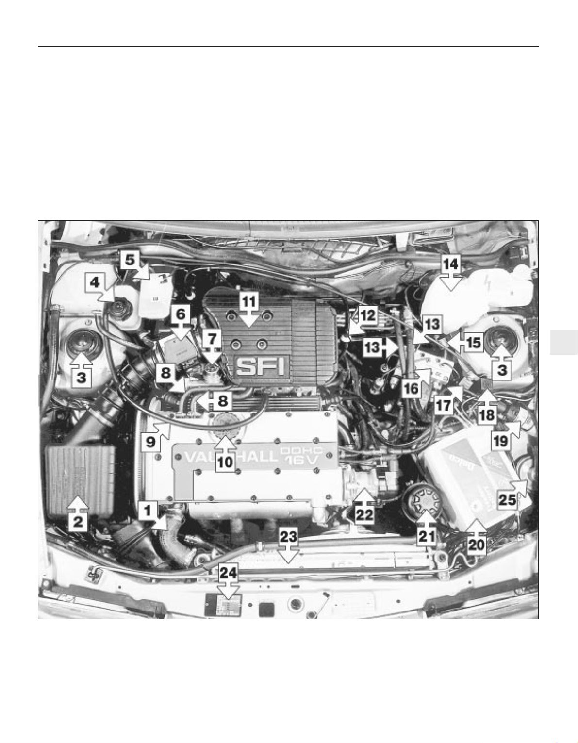
1 Radiator top hose
2 Air cleaner
3 Suspension turrets
4 Coolant filler cap
5 Brake fluid reservoir
6 Air mass meter
7 Fuel pressure regulator
8 Breather hoses
9 Throttle cable
10 Engine oil filler cap
11 Pre-volume chamber
12 Brake servo non-return valve
13 Power steering hoses
14 Windscreen washer reservoir
15 Headlamp washer relay
16 ABS hydraulic unit
17 ABS surge arrester relay
18 Fuel injection control relay
19 Ignition coil
20 Battery
21 Power steering fluid reservoir
22 Distributor
23 Radiator
24 Vehicle identification plate
25 Horn
Underbonnet view of a 2.0 litre 16-valve model
Page 6
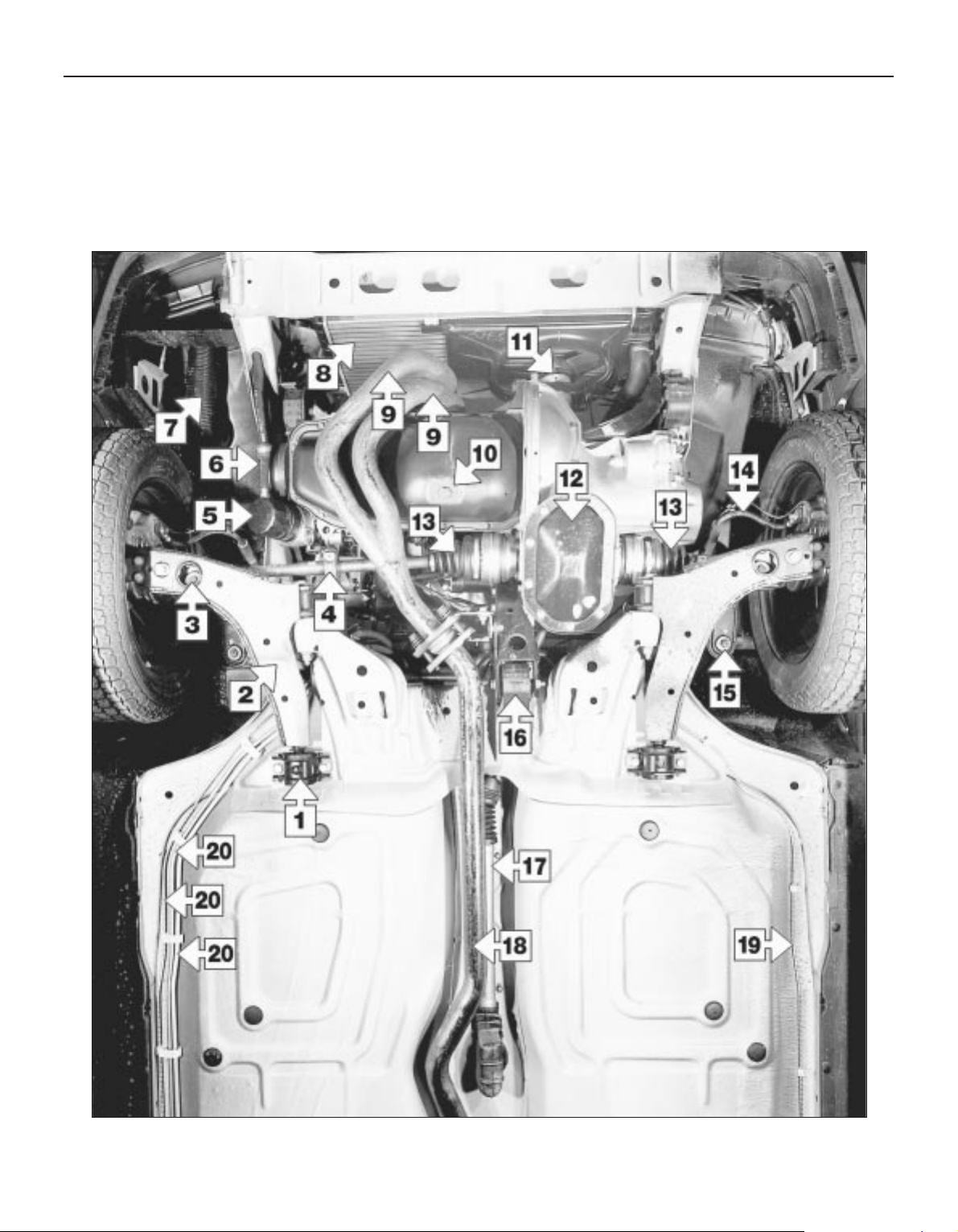
1•6 Maintenance - component location
1 Control arm rear bush
2 Control arm
3 Anti-roll bar link
4 Driveshaft damper weight
5 Engine oil filter
6 Oil cooler hose
7 Air induction trunking
8 Radiator
9 Exhaust downpipes
10 Sump drain plug
11 Radiator fan
12 Gearbox sump
13 Driveshaft bellows
14 Brake hose
15 Steering balljoint attachment
16 Engine/transmission rear mounting
17 Gearchange tube
18 Exhaust pipe
19 Brake pipe
20 Brake and fuel pipes
Front underbody view of a 1.8 litre model - other models similar
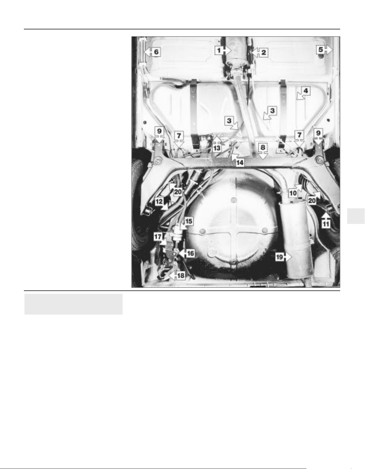
Page 7
Maintenance - introduction 1•7
1
1 Centre silencer
2 Handbrake adjuster
3 Handbrake cables
4 Fuel tank
5 Brake pipe
6 Brake and fuel pipes
7 Brake hoses
8 Axle beam
9 Axle mountings
10 Spring
11 Shock absorber mounting
12 Fuel filler pipe
13 Fuel gauge sender/fuel tank outlet
14 Fuel tank breather
15 Fuel filter*
16 Fuel pressure regulator*
17 Fuel pump*
18 Towing eye
19 Rear silencer
20 Rear brake pipes
*Fuel injection models only
Rear underbody view of a 1.8 litre model -
other models similar
General information
This Chapter is designed to help the home
mechanic maintain his/her vehicle for safety,
economy, long life and peak performance.
The Chapter contains a master
maintenance schedule, followed by sections
dealing specifically with each task on the
schedule. Visual checks, adjustments,
component renewal and other helpful items
are included. Refer to the accompanying
illustrations of the engine compartment and
the underside of the vehicle for the locations
of the various components.
Servicing of your vehicle in accordance with
the mileage/time maintenance schedule and
the following sections will provide a planned
maintenance programme, which should result
in a long and reliable service life. This is a
comprehensive plan, so maintaining some
items but not others at the specified service
intervals, will not produce the same results.
As you service your vehicle, you will
discover that many of the procedures can and should - be grouped together, because of
the particular procedure being performed, or
because of the close proximity of two
otherwise-unrelated components to one
another. For example, if the vehicle is raised
for any reason, the exhaust can be inspected
at the same time as the suspension and
steering components.
The first step in this maintenance
programme is to prepare yourself before the
actual work begins. Read through all the
sections relevant to the work to be carried
out, then make a list and gather together all
the parts and tools required. If a problem is
encountered, seek advice from a parts
specialist, or a dealer service department.
Intensive maintenance
If, from the time the vehicle is new, the
routine maintenance schedule is followed
closely, and frequent checks are made of fluid
levels and high-wear items, as suggested
throughout this manual, the engine will be
kept in relatively good running condition, and
the need for additional work will be minimised.
It is possible that there will be times when
the engine is running poorly due to the lack of
regular maintenance. This is even more likely
if a used vehicle, which has not received
regular and frequent maintenance checks, is
purchased. In such cases, additional work
may need to be carried out, outside of the
regular maintenance intervals.
If engine wear is suspected, a compression
test (Chapter 2) will provide valuable
information regarding the overall performance
of the main internal components. Such a test
can be used as a basis to decide on the
extent of the work to be carried out. If for
example a compression test indicates serious
internal engine wear, conventional
maintenance as described in this Chapter will
not greatly improve the performance of the
engine, and may prove a waste of time and
money, unless extensive overhaul work
(Chapter 2) is carried out first.
2 Introduction
Page 8
1 Frequent oil and filter changes are the most
important preventative maintenance
procedures which can be undertaken by the
DIY owner. As engine oil ages, it becomes
diluted and contaminated, which leads to
premature engine wear.
2 Before starting this procedure, gather
together all the necessary tools and materials.
Also make sure that you have plenty of clean
rags and newspapers handy, to mop up any
spills. Ideally, the engine oil should be warm,
as it will drain more easily, and more built-up
sludge will be removed with it. Take care not
to touch the exhaust or any other hot parts of
the engine when working under the vehicle.
To avoid any possibility of scalding, and to
protect yourself from possible skin irritants
and other harmful contaminants in used
engine oils, it is advisable to wear gloves
when carrying out this work. Access to the
underside of the vehicle will be greatly
improved if it can be raised on a lift, driven
onto ramps, or jacked up and supported on
axle stands (see “Jacking and Vehicle
Support”). Whichever method is chosen,
make sure that the vehicle remains level, or if
it is at an angle, that the drain plug is at the
lowest point. The drain plug is located at the
rear of the sump.
3 Remove the oil filler cap from the camshaft
cover (twist it through a quarter-turn anticlockwise and withdraw it).
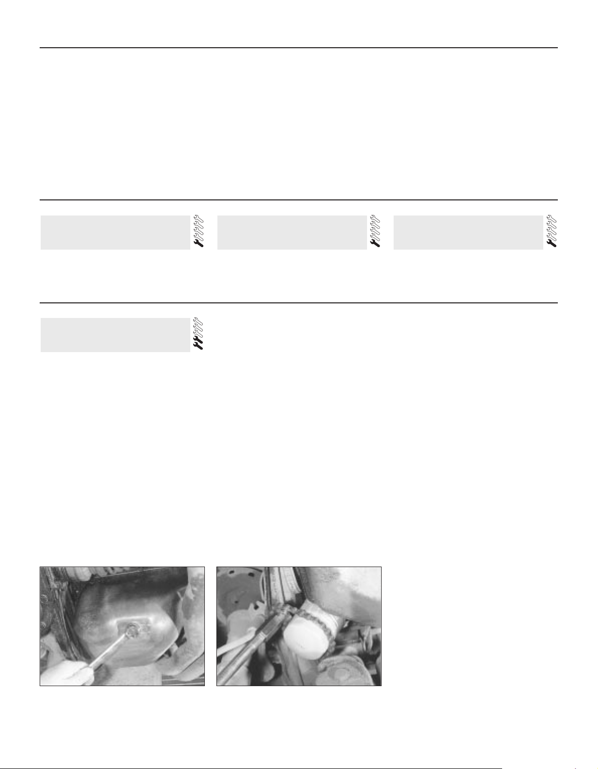
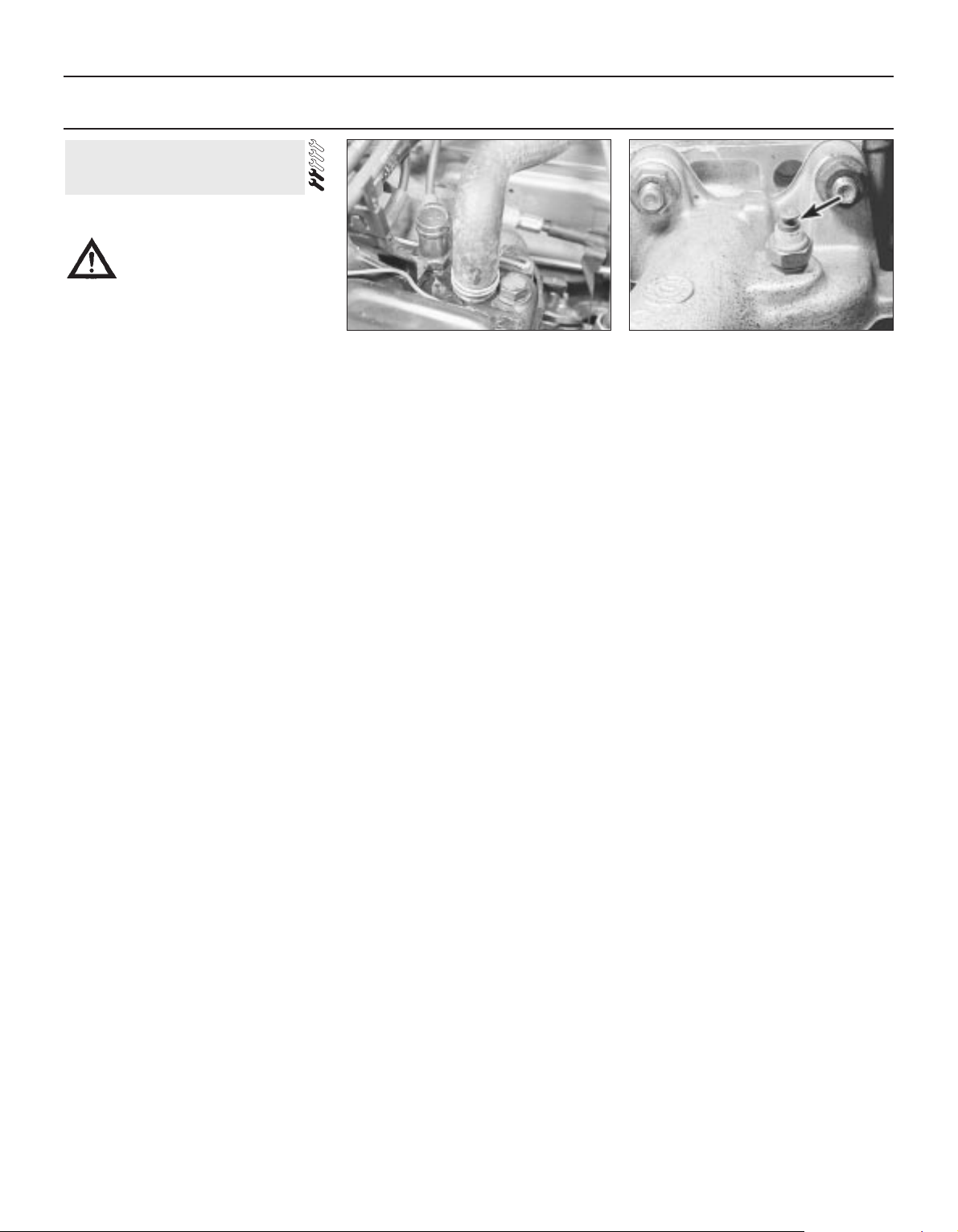
4 Using a spanner, or preferably a socket and
bar, slacken the drain plug about half a turn
(see illustration). Position the draining
container under the drain plug, then remove
the plug completely. If possible, try to keep the
plug pressed into the sump while unscrewing it
by hand the last couple of turns. As the plug
releases from the threads, move it away
sharply, so that the stream of oil from the sump
runs into the container, not up your sleeve!
5 Allow some time for the oil to drain, noting
that it may be necessary to reposition the
container as the oil flow slows to a trickle.
6 After all the oil has drained, wipe the drain
plug and the sealing washer with a clean rag.
Examine the condition of the sealing washer,
and renew it if it shows signs of scoring or
other damage which may prevent an oil-tight
seal. Clean the area around the drain plug
opening, and refit the plug complete with the
washer. Tighten the plug securely, preferably to
the specified torque, using a torque wrench.
7 The oil filter is located at the right-hand end
of the engine.
8 Move the container into position under the
oil filter.
9 Use an oil filter removal tool to slacken the
filter initially, then unscrew it by hand the rest
of the way (see illustration). Empty the oil
from the old filter into the container.
10 Use a clean rag to remove all oil, dirt and
sludge from the filter sealing area on the
engine. Check the old filter to make sure that
the rubber sealing ring has not stuck to the
engine. If it has, carefully remove it.
11 Apply a light coating of clean engine oil to
the sealing ring on the new filter, then screw
the filter into position on the engine. Tighten the
filter firmly by hand only - do not use any tools.
12 Remove the old oil and all tools from
under the vehicle then, if applicable, lower the
vehicle to the ground.
13 Fill the engine through the filler hole in the
camshaft cover, using the correct grade and
type of oil (refer to Section 3 for details of
topping-up). Pour in half the specified quantity
of oil first, then wait a few minutes for the oil
to drain into the sump. Continue to add oil, a
small quantity at a time, until the level is up to
the lower mark on the dipstick. Adding a
further 1.0 litre (approx.) will bring the level up
to the upper mark on the dipstick.
14 Start the engine and run it for a few
minutes, while checking for leaks around the oil
filter seal and the sump drain plug. Note that
there may be a delay of a few seconds before
the low oil pressure warning light goes out when
6 Engine oil and filter renewal
1•8 Maintenance procedures
6.4 Removing the sump drain plug 6.9 Using an oil filter removal tool to
unscrew the oil filter
Every 250 miles or weekly
The following series of operations are those
most often required to improve the
performance of a generally poor-running
engine:
Primary operations
a) Clean, inspect and test the battery
(Section 4).
b) Check all the engine-related fluids
(Section 3).
c) Check the condition and tension of the
auxiliary drivebelt (Section 9).
d) Renew the spark plugs (Section 7).
e) Inspect the ignition system components
(Section 10).
f)| Inspect the ignition HT leads (Section 10).
g) Check the condition of the air filter, and
renew if necessary (Section 24).
h) Check the condition of all hoses, and
check for fluid leaks (Section 8).
If the above operations do not prove fully
effective, carry out the following secondary
operations:
Secondary operations
All items listed under “Primary operations”,
plus the following:
a) Check the charging system (Chapter 5A).
b) Check the fuel system (Chapter 4A or 4B).
c) Renew the air filter (Section 24).
d) Renew the distributor cap and rotor arm
(Section 10).
e) Renew the ignition HT leads (Section 10).
See “Weekly checks” See “Weekly checks” See “Weekly checks”
5 Tyre checks4 Battery check3 Fluid level checks
Every 9000 miles
Page 9
the engine is first started, as the oil circulates
through the new oil filter and the engine oil
galleries before the pressure builds up.
15 Stop the engine, and wait a few minutes
for the oil to settle in the sump once more.
With the new oil circulated and the filter now
completely full, recheck the level on the
dipstick, and add more oil as necessary.
16 Dispose of the used engine oil safely, with
reference to “General repair procedures”.
1 The correct functioning of the spark plugs is
vital for the correct running and efficiency of
the engine. It is essential that the plugs fitted
are appropriate for the engine, the suitable
type being specified at the end of this
Chapter. If the correct type of plug is used
and the engine is in good condition, the spark
plugs should not need attention between
scheduled renewal intervals, except for
adjustment of their gaps. Spark plug cleaning
is rarely necessary, and should not be
attempted unless specialised equipment is
available, as damage can easily be caused to
the firing ends.
2 To remove the plugs, first open the bonnet.
On 1.2 litre models remove the air cleaner as
described in Chapter 4A. On 2.0 litre 16-valve
engines undo the retaining screws and remove
the spark plug lead cover from the engine.
3 Mark the HT leads 1 to 4, to correspond to
the cylinder the lead serves (No 1 cylinder is
nearest the timing belt end of the engine). Pull
the HT leads from the plugs by gripping the
end connectors, not the leads, otherwise the
lead connections may be fractured.
4 It is advisable to remove any dirt from the
spark plug recesses using a clean brush,
vacuum cleaner or compressed air, before
removing the plugs, to prevent the dirt
dropping into the cylinders.
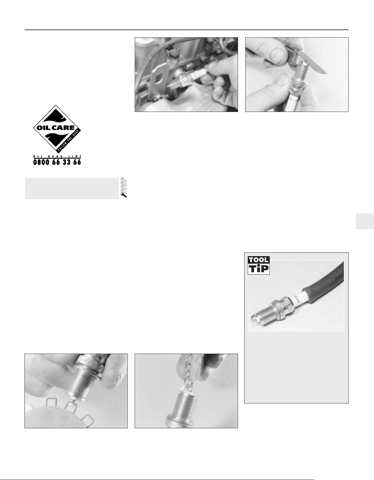
5 Unscrew the plugs using a spark plug
spanner, a suitable box spanner, or a deep
socket and extension bar (see illustration).
Keep the socket in alignment with the spark
plugs, otherwise if it is forcibly moved to either
side, the porcelain top of the spark plug may
be broken off. As each plug is removed,
examine it as follows.
6 Examination of the spark plugs will give a
good indication of the condition of the engine.
If the insulator nose of the spark plug is clean
and white, with no deposits, this is indicative
of a weak mixture or too hot a plug (a hot plug
transfers heat away from the electrode slowly,
while a cold plug transfers heat away quickly).
7 If the tip and insulator nose are covered
with hard black-looking deposits, then this is
indicative that the idle mixture is too rich.
Should the plug be black and oily, then it is
likely that the engine is fairly worn, as well as
the mixture being too rich.
8 If the insulator nose is covered with lighttan to greyish-brown deposits, then the
mixture is correct and it is likely that the
engine is in good condition.
9 The spark plug gap is of considerable
importance as, if it is too large or too small,
the size of the spark and its efficiency will be
seriously impaired. For the best results, the
spark plug gap should be set in accordance
with the Specifications at the end of this
Chapter.
10 To set the spark plug gap, measure the
gap between the electrodes with a feeler
blade, and then bend open, or close, the outer
plug electrode until the correct gap is
achieved (see illustrations). The centre
electrode should never be bent, as this may
crack the insulation and cause plug failure, if
nothing worse.
11 Special spark plug electrode gap
adjusting tools are available from most motor
accessory shops (see illustration).
12 Before fitting the new spark plugs, check
that the threaded connector sleeves on the
top of the plug are tight, and that the plug
exterior surfaces and threads are clean.
13 Screw in the spark plugs by hand where
possible, then tighten them to the specified
torque. Take extra care to enter the plug
threads correctly, as the cylinder head is of
light alloy construction.
14 Reconnect the HT leads in their correct
order. On 1.2 litre models refit the air cleaner
(Chapter 4A) and on 2.0 litre 16-valve models,
refit the spark plug lead cover.
7 Spark plug renewal
Every 9000 miles 1•9
1
Note: It is
antisocial and
illegal to dump
oil down the
drain. To find
the location of
your local oil
recycling bank,
call this
number free.
7.10a Measuring a spark plug electrode
gap using a feeler blade
7.5 Removing a spark plug - 1.6 litre
engine shown
7.10b Measuring a spark plug electrode
gap using a wire gauge
7.11 Adjusting a spark plug electrode gap
using a special tool
It is very often difficult to insert spark
plugs into their holes without crossthreading them. To avoid this, fit a short
length of 5/16-inch internal diameter
hose over the end of the spark plug. The
flexible hose acts as a universal joint to
help align the plug with the plug hole.
Should the plug begin to cross-thread,
the hose will slip on the spark plug,
preventing thread damage to the
aluminium cylinder head.
Page 10
1 Visually inspect the engine joint faces,
gaskets and seals for any signs of water or oil
leaks. Pay particular attention to the areas
around the camshaft cover, cylinder head, oil
filter and sump joint faces. Bear in mind that,
over a period of time, some very slight
seepage from these areas is to be expected;
what you are really looking for is any
indication of a serious leak. Should a leak be
found, renew the offending gasket or oil seal
by referring to the appropriate Chapters in this
manual.
2 Also check the security and condition of all
the engine-related pipes and hoses. Ensure
that all cable-ties or securing clips are in
place, and in good condition. Clips which are
broken or missing can lead to chafing of the
hoses pipes or wiring, which could cause
more serious problems in the future.
3 Carefully check the radiator hoses and
heater hoses along their entire length. Renew
any hose which is cracked, swollen or
deteriorated. Cracks will show up better if the
hose is squeezed. Pay close attention to the
hose clips that secure the hoses to the
cooling system components. Hose clips can
pinch and puncture hoses, resulting in cooling
system leaks. If wire-type hose clips are used,
it may be a good idea to replace them with
screw-type clips.
4 Inspect all the cooling system components
(hoses, joint faces etc.) for leaks. Where any
problems of this nature are found on system
components, renew the component or gasket
with reference to Chapter 3.
5 Where applicable, inspect the automatic
transmission fluid cooler hoses for leaks or
deterioration.
6 With the vehicle raised, inspect the petrol
tank and filler neck for punctures, cracks and
other damage. The connection between the
filler neck and tank is especially critical.
Sometimes, a rubber filler neck or connecting
hose will leak due to loose retaining clamps or
deteriorated rubber.
7 Carefully check all rubber hoses and metal
fuel lines leading away from the petrol tank.
Check for loose connections, deteriorated
hoses, crimped lines and other damage. Pay
particular attention to the vent pipes and
hoses, which often loop up around the filler
neck and can become blocked or crimped.
Follow the lines to the front of the vehicle,
carefully inspecting them all the way. Renew
damaged sections as necessary.
8 From within the engine compartment,
check the security of all fuel hose attachments
and pipe unions, and inspect the fuel hoses
and vacuum hoses for kinks, chafing and
deterioration.
9 Where applicable, check the condition of
the power steering fluid hoses and pipes.
Alternator drivebelt
Checking and adjustment
1 Correct tensioning of the auxiliary drivebelt
will ensure that it has a long life. Beware,
however, of overtightening, as this can cause
excessive wear in the alternator.
2 The belt should be inspected along its
entire length, and if it is found to be worn,
frayed or cracked, it should be renewed as a
precaution against breakage in service. It is
advisable to carry a spare drivebelt of the
correct type in the vehicle at all times.
3 Although special tools are available for
measuring the belt tension, a good
approximation can be achieved if the belt is
tensioned so that there is approximately 13 mm
of free movement under firm thumb pressure at
the mid-point of the longest run between
pulleys. If in doubt, err on the slack side, as an
excessively-tight belt may cause damage to
the alternator or other components.
4 If adjustment is required, loosen the
alternator upper mounting nut and bolt - use
two spanners, one to counterhold the bolt.
Lever the alternator away from the engine
using a wooden lever at the mounting bracket
until the correct tension is achieved, then
tighten the bolt securing the adjuster bracket,
and the alternator mounting nuts and bolts.
On no account lever at the free end of the
alternator, as serious internal damage could
be caused to the alternator.
Removal, renewal and refitting
5 To remove the belt, simply loosen the
mounting nuts and bolts, and the bolt
securing the adjuster bracket, as described
previously, and slacken the belt sufficiently to
slip it from the pulleys. On models with power
steering it will first be necessary to remove the
power steering pump drivebelt as described
below.
6 Refit the belt, and tension it as described
previously. Note that when a new belt has
been fitted it will probably stretch slightly to
start with and the tension should be
rechecked, and if necessary adjusted, after
about 5 minutes running.
Power steering pump drivebelt
Checking and adjustment
7 Refer to the information given in paragraphs 1
to 3, noting that there should be
approximately 8 mm of free movement in the
belt.
8 If adjustment is required, slacken the
adjuster bolt locknut (situated on the base of
the pump) and rotate the adjuster nut as
necessary to tension the belt. Once the belt
tension is correct, securely tighten the
locknut.
Removal, renewal and refitting
9 To remove the belt, simply loosen the
locknut and fully slacken the adjuster nut
sufficiently to slip the drivebelt from the
pulleys.
10 Refit the belt, and tension it as described
previously. Note that when a new belt has
been fitted it will probably stretch slightly to
start with and the tension should be
rechecked, and if necessary adjusted, after
about 5 minutes running.
Alternator/power steering pump
drivebelt - later 1.6 litre models
Checking and adjustment
11 From March 1987 onwards, a single
drivebelt is used for the alternator and power
steering pump on 1.6 litre engines. The
drivebelt is of the ribbed type and runs at a
higher tension than the previous (V) belt.
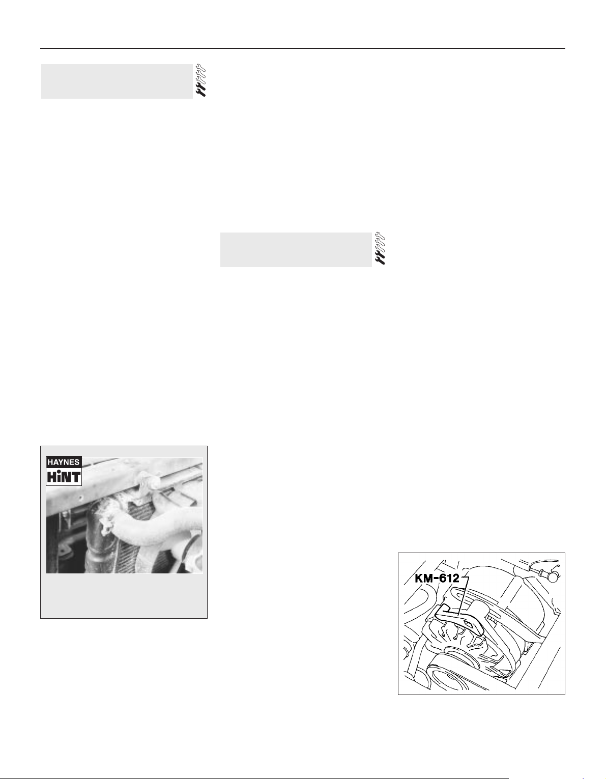
12 To set the tension accurately, make up or
obtain an adapter as shown (see illustration).
13 Slacken the alternator pivot and adjusting
strap bolts and fit the adapter. Using a torque
wrench apply a load of 55 Nm (40 lbf ft) for a
new belt, or 50 Nm (37 lbf ft) for an old belt.
Keep the tension applied and securely tighten
the alternator bolts.
Removal, renewal and refitting
14 To remove the belt, simply loosen the
alternator pivot and strap bolts and slip the
drivebelt from the pulleys.
9 Auxiliary drivebelt check and
renewal
8 Hose and fluid leak check
1•10 Every 9000 miles
9.12 Adapter KM-612 used for setting
drivebelt tension on later 1.6 litre models
A leak in the cooling system will usually
show up as white- or rust-coloured
deposits on the area adjoining the leak.
Page 11
15 Refit the belt, and tension it as described
previously. Note that when a new belt has
been fitted it will probably stretch slightly to
start with and the tension should be
rechecked, and if necessary adjusted, after
about 5 minutes running.
Models with contact breaker
ignition system
1 Renew the contact breaker points and
adjust the gap and dwell angle as described in
Chapter 5B. After adjustment put one or two
drops of engine oil into the centre of the cam
recess where appropriate and smear the
surfaces of the cam itself with petroleum jelly.
Do not over-lubricate as any excess could get
onto the contact point surfaces and cause
ignition difficulties.
2 The spark plug (HT) leads should also be
checked.
3 Ensure that the leads are numbered before
removing them, if not make identification
marks to avoid confusion when refitting. Pull
the leads from the plugs by gripping the end
fitting, not the lead, otherwise the lead
connection may be fractured.
4 Check inside the end fitting for signs of
corrosion, which will look like a white crusty
powder. Push the end fitting back onto the
spark plug ensuring that it is a tight fit on the
plug. If not, remove the lead again and use
pliers to carefully crimp the metal connector
inside the end fitting until it fits securely on the
end of the spark plug.
5 Using a clean rag, wipe the entire length of
the lead to remove any built-up dirt and
grease. Once the lead is clean, check for
burns, cracks and other damage. Do not bend
the lead excessively or pull the lead
lengthwise - the conductor inside might
break.
6 Disconnect the other end of the lead from
the distributor cap. Again, pull only on the end
fitting. Check for corrosion and a tight fit in the
same manner as the spark plug end. If an
ohmmeter is available, check the resistance of
the lead by connecting the meter between the
spark plug end of the lead and the segment
inside the distributor cap. Refit the lead
securely on completion.
7 Check the remaining leads one at a time, in
the same way.
8 If new spark plug (HT) leads are required,
purchase a set for your specific car and
engine.
9 Remove the distributor cap, wipe it clean
and carefully inspect it inside and out for signs
of cracks, carbon tracks (tracking) and worn,
burned or loose contacts; check that the
cap’s carbon brush is unworn, free to move
against spring pressure and making good
contact with the rotor arm. Also inspect the
cap seal for signs of wear or damage and
renew if necessary. Remove and inspect the
rotor arm (see illustrations). It is common
practice to renew the cap and rotor arm
whenever new spark plug (HT) leads are fitted.
When fitting a new cap, remove the leads
from the old cap one at a time and fit them to
the new cap in the exact same location - do
not simultaneously remove all the leads from
the old cap or firing order confusion may
occur. On refitting ensure that the arm is
securely pressed onto the shaft and the cap is
securely fitted.
10 Even with the ignition system in first class
condition, some engines may still occasionally
experience poor starting attributable to damp
ignition components. To disperse moisture a
moister dispersant aerosal can be very
effective.
Models with an electronic ignition
system
11 Check the condition of the HT leads and
distributor components as described above in
paragraphs 3 to 10.
12 Check the ignition timing (Chapter 5C).
1 Before checking the idle speed and mixture
setting, always check first the following.
a) Check that the ignition timing is accurate
(Chapter 5B or 5C).
b) Check that the spark plugs are in good
condition and correctly gapped (Section
25).
c) Check that the accelerator cable and, on
carburettor models, the choke cable
(where fitted) is correctly adjusted (see
relevant Part of Chapter 4).
d) Check that the crankcase breather hoses
are secure with no leaks or kinks (Chapter
2).
e) Check that the air cleaner filter element is
clean (Section 31).
f) Check that the exhaust system is in good
condition (see relevant Part of Chapter 4).
g) If the engine is running very roughly,
check the compression pressures as
described in Chapter 2.
2 Take the car on a journey of sufficient
length to warm it up to normal operating
temperature. Proceed as described under the
relevant sub-heading.
Note: Adjustment should be completed within
two minutes of return, without stopping the
engine. If this cannot be achieved, or if the
radiator electric cooling fan operates, wait for
the cooling fan to stop and clear any excess
fuel from the inlet manifold by racing the
engine two or three times to between 2000
and 3000 rpm, then allow it to idle again.
Carburettor models
3 Connect a tachometer in accordance with
the manufacturer’s instructions.
4 If the idle speed is outside the specified
tolerance (see Specifications), turn the
adjustment screw as necessary (see
illustrations). This will not alter the CO
content of the exhaust gas to any extent.
5 If an exhaust gas analyser is available,
check the exhaust gas CO content as follows.
11 Idle speed and mixture
adjustments
10 Ignition system check
Every 9000 miles 1•11
1
10.9b . . . and pull off the rotor arm from
the distributor shaft (1.6 litre model shown)
11.4a Idle speed adjustment screw
(arrowed) - 32TL carburettor
10.9a Remove the distributor cap . . .
Warning: Voltages produced by
an electronic ignition system are
considerably higher than those
produced by conventional
ignition systems. Extreme care must be
taken when working on the system with the
ignition switched on. Persons with
surgically-implanted cardiac pacemaker
devices should keep well clear of the
ignition circuits, components and test
equipment.
Page 12
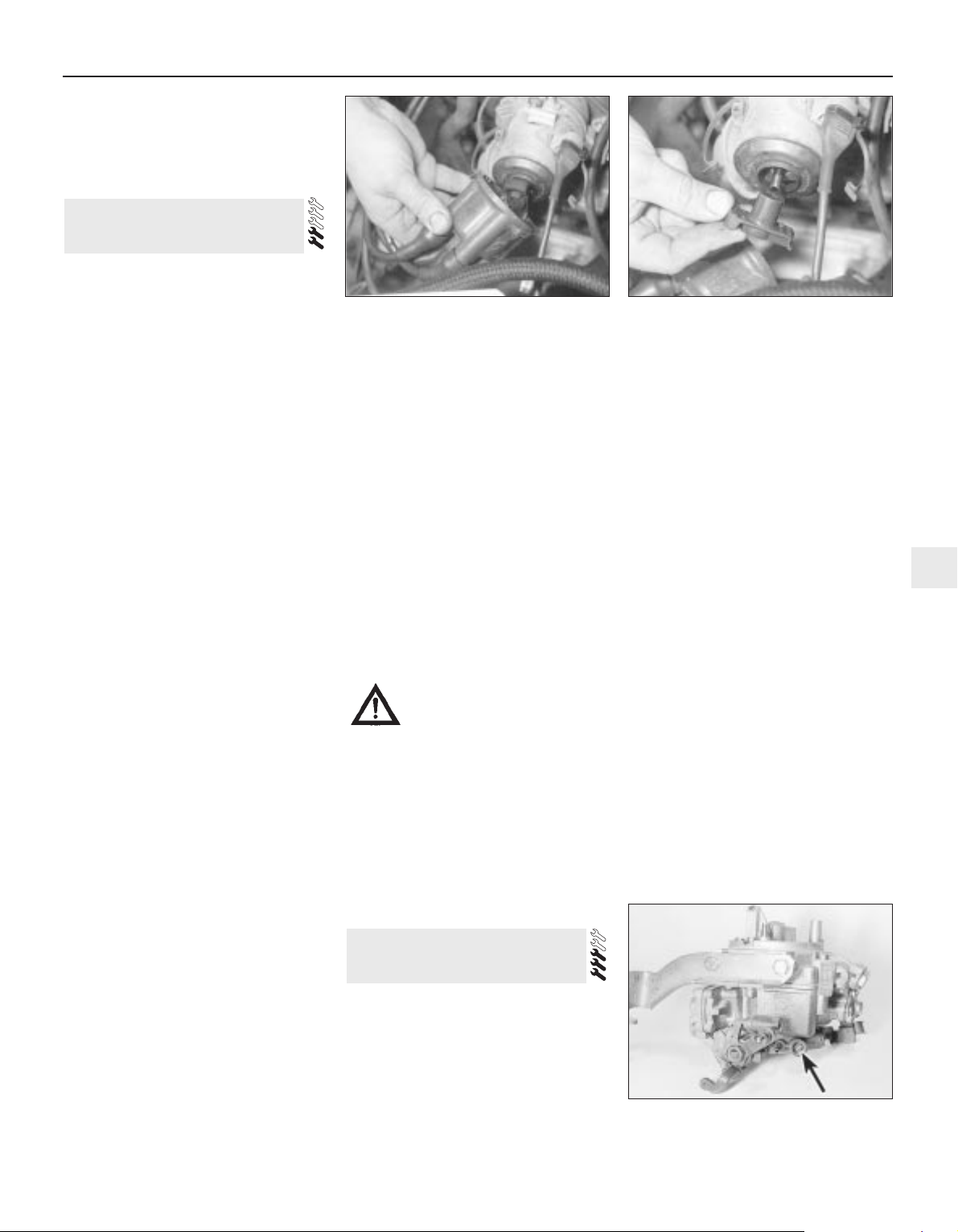
6 Remove the tamperproof cap (where fitted)
from the mixture adjustment screw. Satisfy
yourself that you are not breaking any local or
national laws by so doing.
7 With the engine at normal operating
temperature, check the CO content of the
exhaust gas. If it is outside the permitted
tolerance, turn the mixture adjusting screw as
necessary to correct it (see illustrations).
8 When the adjustments are correct, fit a new
tamperproof cap to the screw and disconnect
the tachometer. Note: On 32TL and Varajet II
carburettors, if it proves difficult to adjust the
idle speed and/or mixture setting then it is
likely that the base idle speed is incorrect.
Setting of this requires the use of an accurate
vacuum gauge and should therefore be
entrusted to a Vauxhall/Opel dealer.
Fuel-injected models
1.8 litre models
9 With the engine at normal operating
temperature, connect a tachometer in
accordance with its manufacturer’s instructions.
10 Allow the engine to idle, and compare the
idle speed with that given in the
Specifications. If adjustment is necessary,
slacken the locknut and turn the idle speed
adjusting screw until the specified speed is
obtained. The adjusting screw is situated on
the throttle valve housing. Tighten the locknut
on completion.
11 If an exhaust gas analyser is available,
check the mixture (CO level) as follows.
12 With the engine idling at the specified
speed, read the CO level and compare it with
that specified.
13 If adjustment is necessary, remove the
tamperproof cap from the mixture adjusting
screw on the airflow sensor (see illustration).
Turn the screw clockwise to enrich the
mixture, and anti-clockwise to weaken it.
14 On completion, re-adjust the idle speed if
necessary. Note that failure to bring the CO
level within the specified range indicates a
fault in the injection system, or a worn engine.
2.0 litre models
15 On all models the idle speed is
automatically controlled by the electronic
control unit and is not adjustable. If it is found
to be incorrect then a fault is present in the
fuel injection/ignition system (Chapter 4B).
16 On models without a catalytic converter,
the mixture (CO level) can be adjusted as
described above in paragraphs 9 and 11 to
14. On 16-valve models the adjusting screw is
on the air mass meter (see illustration).
1•12 Every 9000 miles
11.7d Mixture (CO) adjustment screw (B) 1B1 carburettor
11.13 On 1.8 litre fuel-injected models the
mixture adjustment screw is located under
the cap on the airflow sensor
11.7c Adjusting the mixture (CO) setting Varajet carburettor
11.7a Mixture (CO) adjustment screw 32TL carburettor
11.7b Mixture (CO) adjustment screw cap
(arrowed) 2E3 carburettor
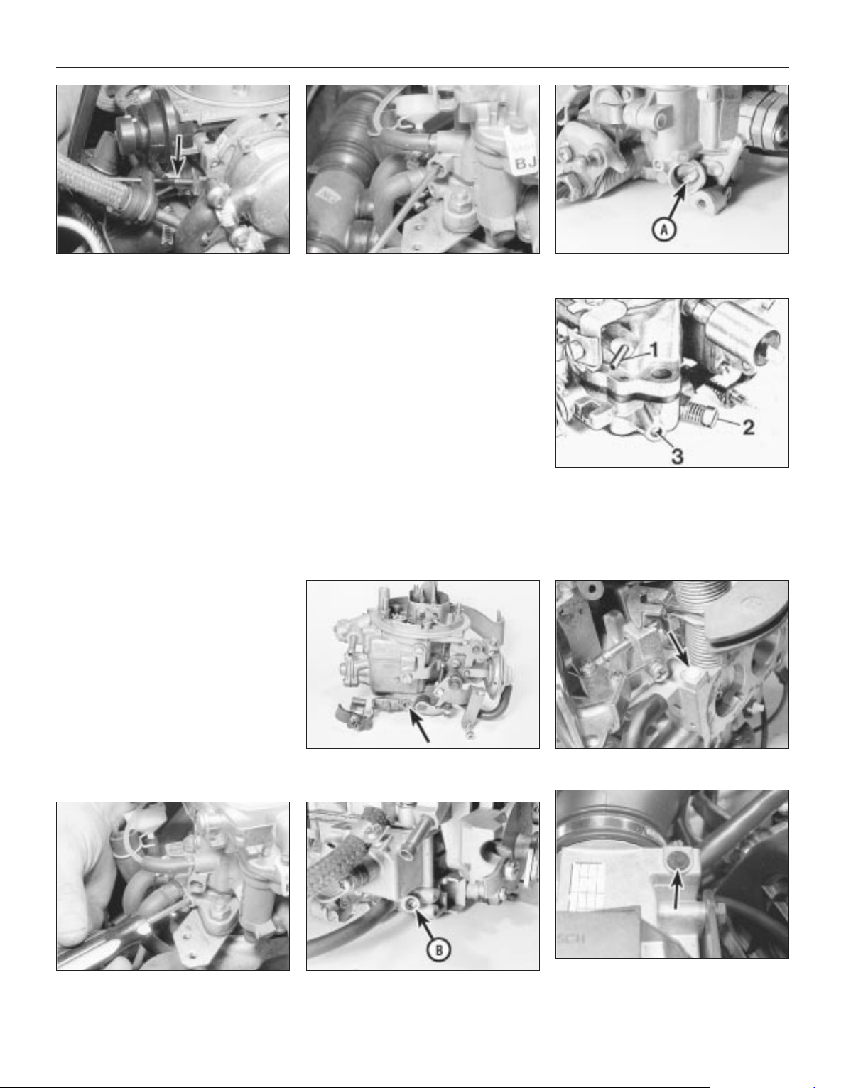
11.4e Idle adjustment points - 35PDSI
carburettor
1 Distributor vacuum take-off
2 Idle speed adjustment screw
3 Mixture (CO level) adjustment screw
11.4b Idle speed adjustment screw
(arrowed) - 2E3 carburettor
11.4c Adjusting the idle speed - Varajet
carburettor
11.4d Idle speed adjusting screw (A) - 1B1
carburettor
Page 13
17 On models fitted with a catalytic
converter, the mixture (CO level) is also
automatically controlled by the electronic
control unit and is not adjustable. If it is found
to be incorrect then a fault is present in the
fuel injection/ignition system (Chapter 4B).
1.4 and 1.6 litre models
18 On 1.4 and 1.6 litre models both the idle
speed and mixture CO content are
automatically controlled by the control unit
and cannot be manually adjusted (See
Chapter 4B). If necessary, they can be
checked by if they are found to be incorrect
then a fault is present in the fuel
injection/ignition system.
Note: On some models the fuel pump may be
a sealed unit, in which case this procedure is
not necessary.
1 Place a wad of rag underneath the fuel
pump to catch the fuel which will be spilt
during the following operation.
2 Undo the retaining screw and remove the
end cover from the fuel pump. Recover the
rubber seal (see illustration).
3 Remove the filter from the cover and wash
it fresh fuel to remove any debris from it.
Inspect the filter for signs of clogging or
splitting and renew it if necessary.
4 Locate the filter in the cover and fit the
rubber seal.
5 Refit the cover to the pump and securely
tighten its retaining screw.
6 Start the engine and check for signs of fuel
leakage.
1 To check the fluid level, the vehicle must be
parked on level ground. Apply the handbrake.
2 If the transmission fluid is cold (ie, if the
engine is cold), the level check must be
completed with the engine idling, within one
minute of the engine being started.
3 With the engine idling, fully depress the
brake pedal, and move the gear selector lever
smoothly through all positions, finishing in
position “P”.
4 With the engine still idling, withdraw the
transmission fluid level dipstick (located at the
left-hand side of the engine compartment,
next to the engine oil level dipstick). Pull up
the lever on the top of the dipstick to release it
from the tube. Wipe the dipstick clean with a
lint-free rag, re-insert it and withdraw it again.
5 If the transmission fluid was cold at the
beginning of the procedure, the fluid level
should be on the “MAX” mark on the side of
the dipstick marked “+20ºC”. Note that 0.4
litres of fluid is required to raise the level from
the “MIN” to the “MAX” mark.
6 If the transmission fluid was at operating
temperature at the beginning of the procedure
(ie, if the vehicle had been driven for at least
12 miles/20 km), the fluid level should be
between the “MIN” and “MAX” marks on the
side of the dipstick marked “+94ºC”. Note
that 0.2 litres of fluid is required to raise the
level from the “MIN” to the “MAX” mark.
7 If topping-up is necessary, stop the engine,
and top-up with the specified type of fluid
through the transmission dipstick tube.
8 Re-check the level, and refit the dipstick on
completion.
1 Check the operation of all the electrical
equipment, ie lights, direction indicators,
horn, etc. Refer to the appropriate sections of
Chapter 12 for details if any of the circuits are
found to be inoperative.
2 Note that stop-light switch adjustment is
described in Chapter 9.
3 Check all accessible wiring connectors,
harnesses and retaining clips for security, and
for signs of chafing or damage. Rectify any
faults found.
Check the condition of the wiper blades. If
they are cracked, or show any signs of
deterioration, or if they fail to clean the glass
effectively, renew the blades. Ideally, the
wiper blades should be renewed annually as a
matter of course.
To remove a wiper blade, pull the arm away
from the glass until it locks. Swivel the blade
through 90º, then squeeze the locking clip,
and detach the blade from the arm. When
fitting the new blade, make sure that the blade
locks securely into the arm, and that the blade
is orientated correctly.
Using a torque wrench on each wheel bolt
in turn, ensure that the bolts are tightened to
the specified torque.
Front brakes
1 Apply the handbrake, then jack up the front
of the vehicle and support securely on axle
stands; remove the roadwheels (see “Jacking
and Vehicle Support “).
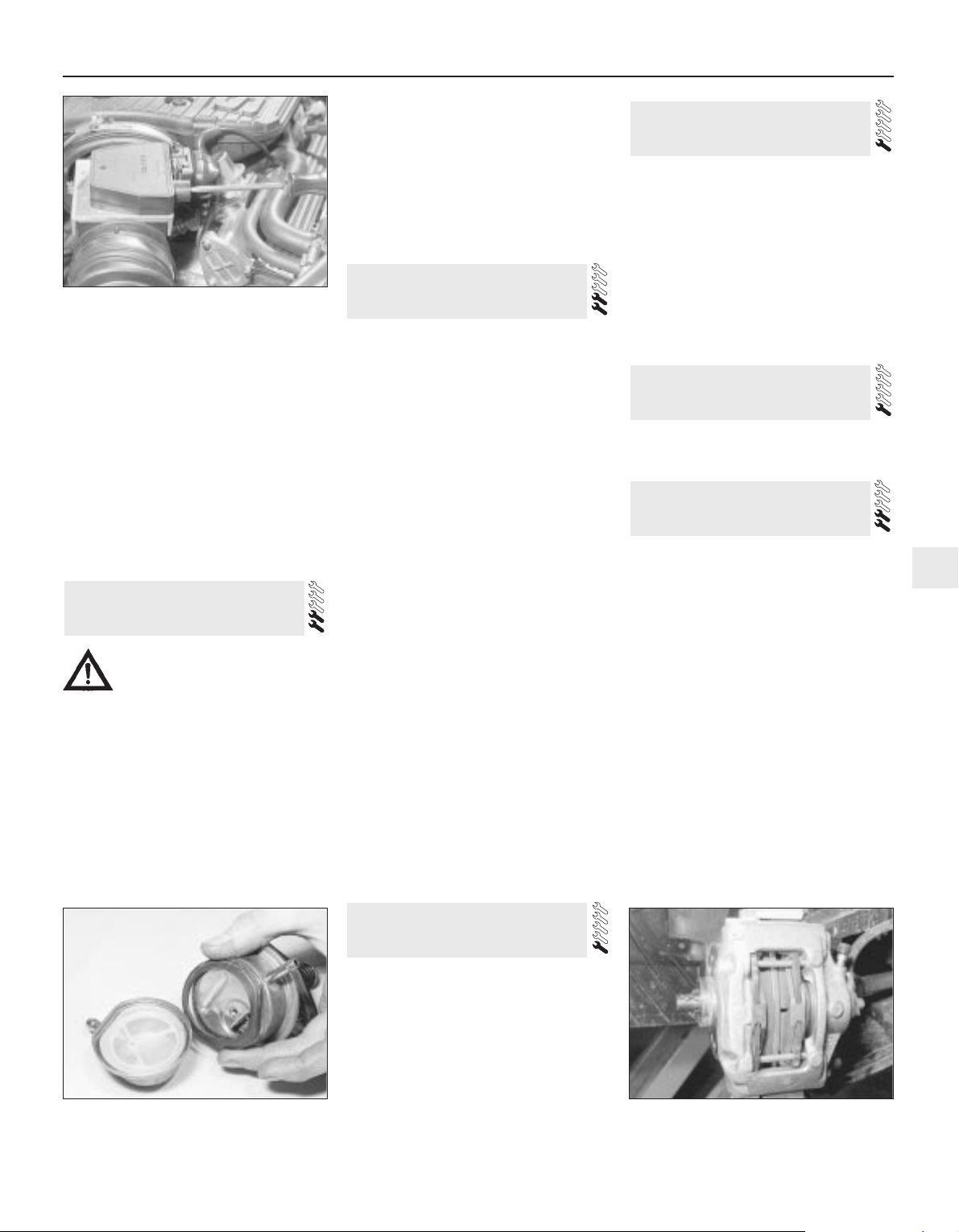
2 For a quick check, the thickness of friction
material remaining on each pad can be
measured through the slot in the front of the
caliper body (see illustration). If any pad is
worn to the minimum thickness or less, all
four pads must be renewed (see Chapter 9).
3 For a complete check, the brake pads
should be removed and cleaned. This will allow
the operation of the caliper to be checked, and
the condition of the brake disc itself to be fully
examined on both sides (see Chapter 9).
Rear brakes
4 Chock the front wheels, then jack up the
rear of the vehicle and support securely on
axle stands; remove the roadwheels (see
“Jacking and Vehicle Support “). Inspect the
pads as described in paragraphs 2 and 3.
17 Brake pad, caliper and disc
check
16 Roadwheel bolt tightness
check
15 Wiper blade check
14 Electrical system check
13 Automatic transmission fluid
level check
12 Fuel pump filter cleaning -
carburettor models
Every 9000 miles 1•13
1
12.2 Removing the fuel pump cover, filter
and rubber seal - carburettor models
17.2 The thickness of the brake pads are
visible through the caliper aperture
11.16 Adjusting the mixture (CO) setting -
2.0 litre 16-valve models
Warning: Before carrying out
the following operation refer to
the precautions given in Safety
first! and follow them implicitly.
Petrol is a highly dangerous and volatile
liquid and the precautions necessary
when handling it cannot be overstressed
Page 14
Refer to Chapter 10, Section 9.
Rear drum brake models
1 Normal adjustment of the handbrake takes
place automatically due to the self-adjusting
mechanism of the rear brakes. To
compensate for cable stretch, or after a new
cable has been fitted or the adjustment has
otherwise been disturbed, proceed as follows.
2 Chock the front wheels, release the
handbrake and raise and support the rear of
the vehicle so that the rear wheels are clear of
the ground.
3 Tighten the nut on the handbrake cable
yoke until the rear wheels start to become stiff
to turn, then back it off until they are free
again (see illustration).
4 Check that the handbrake starts to take
effect at the second notch of lever movement,
and is fully applied by the fourth or fifth notch.
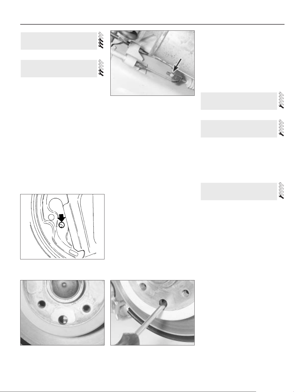
5 A further check may be made by removing
the plug in the brake backplate (see
illustration). When adjustment is correct, the
pin on the handbrake operating lever is clear
of the shoe web by approximately 3 mm with
the handbrake released.
6 When adjustment is correct, apply a smear
of grease to the threads of the cable end
fitting to prevent corrosion. Lower the vehicle,
apply the handbrake and remove the wheel
chocks.
Rear disc brake models
7 Before checking handbrake adjustment,
drive for approximately 300 metres at low
speed with the handbrake lightly applied. This
will clean off any rust or glaze from the drums
and shoes.
8 Chock the front wheels and engage a gear.
Slacken the rear wheel bolts. Raise and
support the rear of the vehicle and remove the
rear wheels.
9 Release the handbrake, then reapply it by
two notches.
10 Slacken off the adjuster nut on the
handbrake cable yoke (located to the left of
the silencer) until it is at the end of its travel. If
a silencer heat shield is fitted, access will be
improved by removing it.
11 Turn a brake disc to bring the adjuster
hole (the large unthreaded hole) into line with
the adjuster at the bottom of the brake shoes.
Using a screwdriver through the hole, turn the
adjuster wheel until the shoes are against the
disc, then back it off again until the disc is just
free to turn without the shoes dragging (see
illustrations).
12 Repeat the operation on the other brake.
13 Tighten the cable adjuster nut until the
shoes start to drag again. This should happen
on both sides.
14 Release and fully reapply the handbrake a
couple of times. Check that the discs turn
freely when the control is fully released, and
that the brake is fully applied at the sixth
notch.
15 Refit the exhaust heat shield if it was
removed. Refit the wheels, lower the vehicle
and tighten the wheel bolts.
Refer to Chapter 8, Section 5.
Lubricate the hinges of the bonnet, doors
and tailgate with a light general-purpose oil.
Similarly, lubricate all latches, locks and lock
strikers. At the same time, check the security
and operation of all the locks, adjusting them
if necessary (see Chapter 11).
Lightly lubricate the bonnet release
mechanism and cable with a suitable grease.
1 With the engine cold (at least an hour after
the vehicle has been driven), check the
complete exhaust system from the engine to
the end of the tailpipe. The exhaust system is
most easily checked with the vehicle raised on
a hoist, or suitably supported on axle stands
(see “Jacking and Vehicle Support”). so that
the exhaust components are readily visible
and accessible.
2 Check the exhaust pipes and connections
for evidence of leaks, severe corrosion and
damage. Make sure that all brackets and
mountings are in good condition, and that all
relevant nuts and bolts are tight. Leakage at
any of the joints or in other parts of the system
will usually show up as a black sooty stain in
the vicinity of the leak. Reputable exhaust
repair systems can be used for effective
repairs to exhaust pipes and silencer boxes,
including ends and bends. Check for an MOTapproved permanent exhaust repair.
3 Rattles and other noises can often be
traced to the exhaust system, especially the
brackets and mountings. Try to move the
pipes and silencers. If the components are
able to come into contact with the body or
suspension parts, secure the system with new
mountings. Otherwise separate the joints (if
possible) and twist the pipes as necessary to
provide additional clearance.
22 Exhaust system check
21 Hinge and lock lubrication
20 Driveshaft CV joint and gaiter
check
19 Handbrake adjustment
18 Rear wheel bearing
adjustment
1•14 Every 9000 miles
19.5 Check the handbrake lever pin
(arrowed) is correctly positioned as
described in text
19.3 Handbrake cable adjusting nut
(arrowed) on yoke - rear drum brake
models
19.11a On models with rear disc brakes
the handbrake shoe adjuster wheel is
accessible through the hole in the disc . . .
19.11b . . . and can be adjusted using a
suitable screwdriver
Page 15
Instruments and electrical
equipment
1 Check the operation of all instruments and
electrical equipment.
2 Make sure that all instruments read
correctly, and switch on all electrical
equipment in turn, to check that it functions
properly.
Steering and suspension
3 Check for any abnormalities in the steering,
suspension, handling or road “feel”.
4 Drive the vehicle, and check that there are
no unusual vibrations or noises.
5 Check that the steering feels positive, with
no excessive “sloppiness”, or roughness, and
check for any suspension noises when
cornering and driving over bumps.
Drivetrain
6 Check the performance of the engine,
clutch (where applicable), gearbox/
transmission and driveshafts.
7 Listen for any unusual noises from the
engine, clutch and gearbox/transmission.
8 Make sure that the engine runs smoothly
when idling, and that there is no hesitation
when accelerating.
9 Check that, where applicable, the clutch
action is smooth and progressive, that the
drive is taken up smoothly, and that the pedal
travel is not excessive. Also listen for any
noises when the clutch pedal is depressed.
10 On manual gearbox models, check that all
gears can be engaged smoothly without
noise, and that the gear lever action is not
abnormally vague or “notchy”.
11 On automatic transmission models, make
sure that all gearchanges occur smoothly,
without snatching, and without an increase in
engine speed between changes. Check that
all the gear positions can be selected with the
vehicle at rest. If any problems are found, they
should be referred to a Vauxhall/Opel dealer.
12 Listen for a metallic clicking sound from
the front of the vehicle, as the vehicle is driven
slowly in a circle with the steering on full-lock.
Carry out this check in both directions. If a
clicking noise is heard, this indicates wear in a
driveshaft joint, in which case renew the joint
if necessary.
Check the operation and
performance of the braking
system
13 Make sure that the vehicle does not pull to
one side when braking, and that the wheels
do not lock prematurely when braking hard.
14 Check that there is no vibration through
the steering when braking.
15 Check that the handbrake operates
correctly without excessive movement of the
lever, and that it holds the vehicle stationary
on a slope.
16 Test the operation of the brake servo unit
as follows. With the engine off, depress the
footbrake four or five times to exhaust the
vacuum. Hold the brake pedal depressed,
then start the engine. As the engine starts,
there should be a noticeable “give” in the
brake pedal as vacuum builds up. Allow the
engine to run for at least two minutes, and
then switch it off. If the brake pedal is
depressed now, it should be possible to
detect a hiss from the servo as the pedal is
depressed. After about four or five
applications, no further hissing should be
heard, and the pedal should feel considerably
harder.
23 Road test
Carburettor models
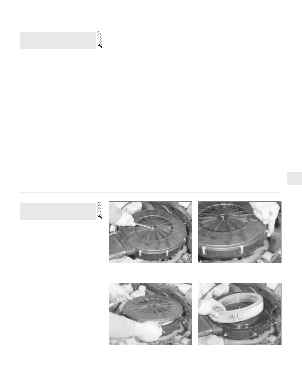
1 To remove the air cleaner element, remove
the air cleaner cover. This is secured by a
centre nut or bolt, or by three screws.
Additionally, release the spring clips around
the edge of the cover or, if spring clips are not
fitted, carefully prise around the lower edge of
the cover with your fingers to release the
retaining lugs (see illustrations).
2 With the cover removed, lift out the element
(see illustrations).
3 Wipe inside the air cleaner, being careful
not to introduce dirt into the carburettor
throat. It is preferable to remove the air
cleaner completely. Remember to clean the
inside of the air cleaner cover.
4 Fit the new element, then refit and secure
the cover. Observe any cover-to-body
alignment lugs or slots.
Fuel injection models
1.4 and 1.6 litre models
5 Refer to paragraphs 1 to 4.
1.8 and 2.0 litre 8-valve models
6 The air cleaner on these models is
contained within the airflow sensor housing.
24 Air cleaner filter element
renewal
Every 18 000 miles 1•15
1
24.1a On carburettor models, undo the
retaining nut (on some models the lid will
be retained by screws) . . .
24.1b . . . and release the retaining
clips . . .
24.2b . . . and withdraw the filter element24.2a . . . then lift off the air cleaner lid . . .
Every 18 000 miles
Page 16
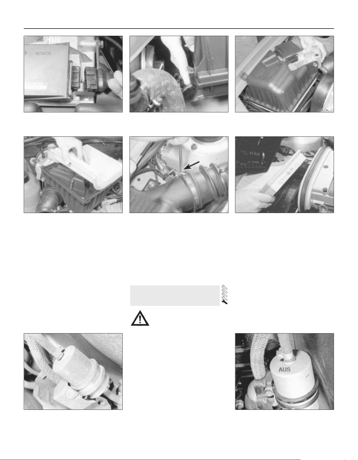
7 Release the locking clip, and disconnect
the plug from the airflow sensor (see
illustration). Disconnect the air trunking.
8 Release the spring clips, and lift off the air
cleaner cover with airflow sensor attached.
The element will probably come away with the
cover (see illustrations). Do not drop or jar
the airflow sensor.
9 Wipe clean the inside of the air cleaner an
fit a new element to the cover, engaging the
element seal in the cover recess (see
illustration). Refit and secure the cover, then
reconnect the airflow sensor plug. Refit the air
trunking.
2.0 litre 16-valve models
10 Disconnect the trunking which connects
the air cleaner to the mass meter (see
illustration).
11 Release the four spring clips which secure
the air cleaner lid. Remove the lid.
12 Remove the element and wipe clean the
inside of the filter housing and lid.
13 Fit a new element, sealing lip uppermost
(see illustration). Refit and secure the lid and
trunking.
1 The fuel filter is located under the rear of the
vehicle. Chock the front wheels, jack up the rear
of the vehicle, and support securely on axle
stands (see “Jacking and Vehicle Support“).
2 Disconnect the battery negative lead and
position a suitable container below the fuel
filter, to catch spilt fuel.
3 Slacken the retaining clips and, bearing in
mind the information given in Chapter 4B on
depressurising the fuel system, disconnect
both hoses. To minimise fuel loss clamp the
hoses either side of the filter or be prepared to
plug the hose ends as they are disconnected
(see illustration).
4 Loosen the clamp bolt, and withdraw the
filter from its clamp. Note the orientation of
the fuel flow direction indicator on the filter.
This will be in the form of an arrow which
points in the direction of the fuel flow, or the
filter will have AUS (out) stamped on its outlet
side (see illustration).
5 Recover the mounting rubber from the old
filter, and transfer it to the new filter.
6 Fit the new filter making sure its fuel flow
direction indicator is facing the right way.
7 Reconnect the hose and securely tighten
their retaining clips.
8 Start the engine and check the disturbed
hose connections for signs of leakage.
25 Fuel filter renewal - fuel
injection models
1•16 Every 18 000 miles
24.8b . . . and remove the air cleaner
housing cover, complete with the filter
element
24.8a . . . then release the retaining
clips . . .
24.7 On 1.8 and 2.0 litre 8-valve models,
disconnect the airflow sensor wiring
connector . . .
24.13 Fitting a new air cleaner element -
2.0 litre 16-valve models
25.4 Fuel filter directional marking25.3 Fuel filter showing mounting and
hose connections
24.10 Disconnecting the trunking from the
air cleaner - 2.0 litre 16-valve models
24.9 On fitting, ensure the element is
correctly seated in the cover groove
Warning: Before carrying out
the following operation refer to
the precautions given in Safety
first! and follow them implicitly.
Petrol is a highly dangerous and volatile
liquid and the precautions necessary
when handling it cannot be overstressed.
Page 17
Referring to the relevant Section of Chapter
4A, remove the filter, wash it fresh fuel to
remove any debris from it. Inspect the filter for
signs of clogging or splitting and renew it if
necessary. Refit the filter and reconnect the
fuel hose.
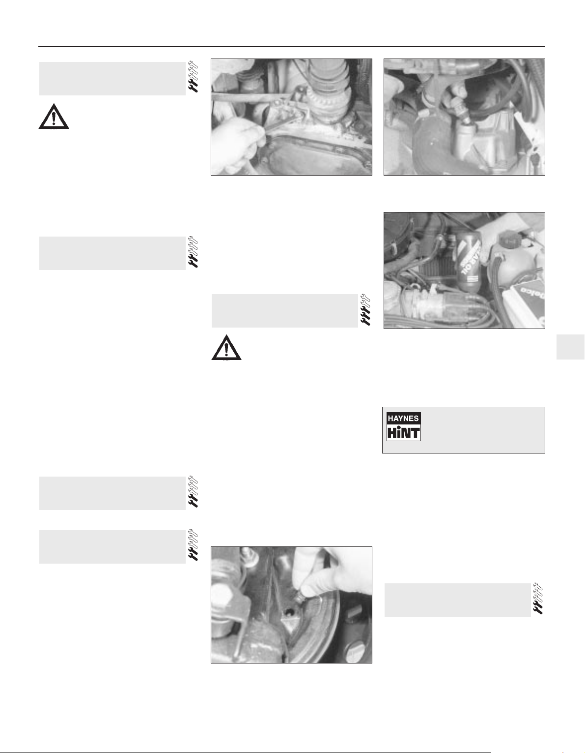
1 Ensure that the vehicle is standing on level
ground and the handbrake applied.
2 Working underneath the vehicle, unscrew
the transmission oil level plug (see
illustration). The level plug is located beside
the driveshaft inner CV joint; on 1.2, 1.3, 1.4
and later 1.6 litre models the plug is on the
left-hand side of the transmission, and on all
other models it is on the right-hand side.
3 The oil level should be up to the lower edge
of the level plug hole.
4 If necessary, top-up with oil through the
breather/filler orifice in the gear selector
cover. Unscrew the breather/filler plug, and
top-up with the specified grade of oil, until oil
just begins to run from the level plug hole. A
funnel may be helpful, to avoid spillage (see
illustrations). Do not overfill - if too much oil
is added, wait until the excess has run out of
the level plug hole. Refit the level plug and the
breather/filler plug on completion.
Refer to Chapter 6
1 Chock the front wheels, then jack up the
rear of the vehicle, and support it securely on
axle stands (see “Jacking and Vehicle
Support”).
2 For a quick check, the thickness of friction
material remaining on one of the brake shoes
can be observed through the hole in the brake
backplate which is exposed by prising out the
sealing grommet (see illustration). If a rod of
the same diameter as the specified minimum
friction material thickness is placed against
the shoe friction material, the amount of wear
can be assessed. A torch or inspection light
will probably be required. If the friction
material on any shoe is worn down to the
specified minimum thickness or less, all four
shoes must be renewed as a set.
3 For a comprehensive check, the brake
drum should be removed and cleaned. This
will allow the wheel cylinders to be checked,
and the condition of the brake drum itself to
be fully examined (see Chapter 9).
1 The procedure is similar to that for the
bleeding of the hydraulic system as described
in Chapter 9, except that the brake fluid
reservoir should be emptied by siphoning,
using a clean poultry baster or similar before
starting, and allowance should be made for
the old fluid to be expelled when bleeding a
section of the circuit.
2 Working as described in Chapter 9, open
the first bleed screw in the sequence and
pump the brake pedal gently until nearly all
the old fluid has been emptied from the
master cylinder reservoir. Top-up to the `MAX’
level with new fluid and continue pumping
until only the new fluid remains in the reservoir
and new fluid can be seen emerging from the
bleed screw. Tighten the screw and top the
reservoir level up to the `MAX’ level line.
3 Work through all the remaining bleed screws
in sequence until new fluid can be seen at all of
them. Be careful to keep the master cylinder
reservoir topped up to above the `MIN’ level at
all times or air may enter the system and
greatly increase the length of the task.
4 When the operation is complete, check that
all bleed screws are securely tightened and
that their dust caps are refitted. Wash off all
traces of spilt fluid and recheck the master
cylinder reservoir fluid level.
5 Check the operation of the brakes before
taking the car on the road.
Accurate adjustment of the headlight beam
is only possible using optical beam-setting
equipment, and this work should therefore be
carried out by a Vauxhall/Opel dealer or
service station with the necessary facilities.
Basic adjustments can be carried out in an
emergency, and further details are given in
Chapter 12.
31 Headlamp aim check
30 Brake fluid renewal
29 Rear brake shoe, wheel
cylinder and drum check
28 Clutch adjustment check
27 Manual transmission oil level
check
26 Carburettor fuel inlet filter
cleaning
Every 18 000 miles 1•17
1
Warning: Before carrying out the
following operation refer to the
precautions given in Safety first!
and follow them implicitly. Petrol
is a highly dangerous and volatile liquid
and the precautions necessary when
handling it cannot be overstressed.
29.2 Removing the sealing grommet from
the inspection hole in the rear brake
backplate
27.4a To top up, unscrew the
breather/filler plug from the top of the
transmission . . .
27.2 Removing the manual transmission
level plug - early 1.6 litre model shown
27.4b . . . then top up via the breather/filler
plug orifice
Warning: Brake hydraulic fluid
can harm your eyes and damage
painted surfaces, so use
extreme caution when handling
and pouring it. Do not use fluid
that has been standing open for some
time as it absorbs moisture from the air.
Excess moisture can cause a dangerous
loss of braking effectiveness.
Old hydraulic fluid is
invariably much darker in
colour than the new, making
it easy to distinguish the two.
Page 18
1•18 Maintenance procedures
Cooling system draining
1 To drain the cooling system, remove the
expansion tank filler cap. Turn the cap anticlockwise until it reaches the first stop. Wait
until any pressure remaining in the system is
released then push the cap down, turn it anticlockwise to the second stop and lift off.
2 Position a suitable container beneath the
radiator bottom hose union.
3 Slacken the hose clip and ease the hose
from the radiator stub. If the hose joint has not
been disturbed for some time, it will be
necessary to gently manipulate the hose to
break the joint. Do not use excessive force, or
the radiator stub could be damaged. Allow the
coolant to drain into the container.
4 As no cylinder block drain plug is fitted and
the radiator bottom hose union may be
situated halfway up the radiator, this may not
fully drain the cooling system.
5 If the coolant has been drained for a reason
other than renewal, then provided it is clean
and less than two years old, it can be re-used.
6 Reconnect the hose and securely tighten its
retaining clip on completion of draining.
Cooling system flushing
7 If coolant renewal has been neglected, or if
the antifreeze mixture has become diluted,
then in time, the cooling system may gradually
lose efficiency, as the coolant passages
become restricted due to rust, scale deposits,
and other sediment.
8 The cooling system efficiency can be
restored by flushing the system clean.
9 The radiator should be flushed
independently of the engine to avoid
unnecessary contamination.
Radiator flushing
10 To flush the radiator, drain the cooling
system then proceed as follows.
11 Slacken the retaining clips and disconnect
the top and bottom hoses from the radiator.
12 Insert a garden hose into the radiator top
inlet. Direct a flow of clean water through the
radiator, and continue flushing until clean
water emerges from the radiator bottom outlet.
13 If after a reasonable period, the water still
does not run clear, the radiator can be flushed
with a good proprietary cleaning agent. It is
important that the manufacturers instructions
are followed carefully. If the contamination is
particularly bad, insert the hose in the radiator
bottom outlet, and flush the radiator in reverse.
Engine flushing
14 To flush the engine, remove the
thermostat as described in Chapter 3, then
temporarily refit the thermostat cover.
15 With the top and bottom hoses
disconnected from the radiator, insert a
garden hose into the radiator top hose. Direct
a clean flow of water through the engine, and
continue flushing until clean water emerges
from the radiator bottom hose.
16 On completion of flushing, refit the
thermostat and reconnect the hoses with
reference to Chapter 3.
Cooling system filling
17 Before attempting to fill the cooling system,
make sure that all hoses and clips are in good
condition, and that the clips are tight. Note that
an antifreeze mixture must be used all year
round, to prevent corrosion of the engine
components (see following sub-Section). Also
check that the radiator and cylinder block drain
plugs are in place and tight.
18 Remove the expansion tank filler cap.
19 On 1.2 litre models, disconnect the heater
hose from the cylinder head, on 1.3, 1.4 and
later 1.6 litre engines models, disconnect the
wire and unscrew the coolant temperature
sender from the inlet manifold. On early 1.6,
and all 1.8 and 2.0 litre models, unscrew the
bleed screw which is situated in the
thermostat housing cover (where no bleed
screw is fitted, unscrew the temperature
sender unit) (see illustrations).
20 Fill the system by slowly pouring the
coolant into the expansion tank to prevent
airlocks from forming.
21 If the coolant is being renewed, begin by
pouring in a couple of litres of water, followed
by the correct quantity of antifreeze, then topup with more water.
22 When coolant free of air bubbles emerges
from the orifice, reconnect the heater hose (1.2
litre models) or refit the coolant temperature
sender/bleed screw (as applicable) and tighten
it securely (all other models).
23 Top-up the coolant level to the “KALT” (or
“COLD”) mark on the expansion tank, then
refit the expansion tank cap.
24 Start the engine and run it until it reaches
normal operating temperature, then stop the
engine and allow it to cool.
25 Check for leaks, particularly around
disturbed components. Check the coolant
level in the expansion tank, and top-up if
necessary. Note that the system must be cold
before an accurate level is indicated in the
expansion tank. If the expansion tank cap is
removed while the engine is still warm, cover
the cap with a thick cloth, and unscrew the
cap slowly to gradually relieve the system
pressure (a hissing sound will normally be
heard). Wait until any pressure remaining in
the system is released, then continue to turn
the cap until it can be removed.
Antifreeze mixture
26 The antifreeze should always be renewed
at the specified intervals. This is necessary
not only to maintain the antifreeze properties,
but also to prevent corrosion which would
otherwise occur as the corrosion inhibitors
become progressively less effective.
27 Always use an ethylene-glycol based
antifreeze which is suitable for use in mixed
metal cooling systems. The quantity of
antifreeze and levels of protection are
indicated in the Specifications.
28 Before adding antifreeze the cooling
system should be completely drained,
preferably flushed, and all hoses checked for
condition and security.
29 After filling with antifreeze, a label should
be attached to the expansion tank stating the
type and concentration of antifreeze used and
the date installed. Any subsequent topping up
should be made with the same type and
concentration of antifreeze.
30 Do not use engine antifreeze in the screen
washer system, as it will cause damage to the
vehicle paintwork. A proprietry screen should
be added to the washer system in the
recommended quantities.
32 Coolant renewal
Every 2 Years
32.19a On 1.2 litre models, bleed the
cooling system through the cylinder head
heater hose outlet
32.19b On 1.3 litre models, unscrew
temperature gauge sender unit from the
manifold to bleed the cooling system
Warning: Wait until the engine is
cold before starting this
procedure. Do not allow
antifreeze to come in contact
with your skin or painted surfaces of the
vehicle. Rinse off spills immediately with
plenty of water. Never leave antifreeze
lying around in an open container or in a
puddle in the driveway or on the garage
floor. Children and pets are attracted by its
sweet smell. Antifreeze is fatal if ingested.
Page 19

1 Allow the transmission to cool down before
draining, as the fluid: can be very hot indeed.
2 Remove all the fluid pan screws except one
which should be unscrewed through several
turns.
3 Release the fluid pan from its gasket and as
the end of the pan tilts downwards, catch the
fluid in a suitable container.
4 Remove the remaining screw and the pan.
Peel off the gasket (where fitted) or remove all
traces of sealant (as applicable).
5 Pull the filter mesh from its securing clips
and recover its sealing ring. Clean the filter in
a high flash-point solvent and allow it to dry. If
the filter is clogged or split it must be
renewed.
6 Fit a new O-ring and refit the filter securely.
7 Ensure that the fluid pan and transmission
mating surfaces are clean and dry and bolt on
the fluid pan using a new gasket. Where no
gasket is fitted, apply a bead of sealant about
5.0 mm thick to clean surfaces. The fluid pan
which is fitted with a gasket can be identified
by the strengthening ribs on the pan flanges.
The pan for use with silicone sealant has plain
flanges.
8 Fill the transmission with the specified
quantity of fluid and then check the level as
described in Section 13.
33 Automatic transmission fluid
renewal
Maintenance procedures 1•19
1
Specifications
Cooling system
Antifreeze mixtures:
Protection down to -15ºC . . . . . . . . . . . . . . . . . . . . . . . . . . . . . . . . . . 28% antifreeze
Protection down to -30ºC . . . . . . . . . . . . . . . . . . . . . . . . . . . . . . . . . . 50% antifreeze
Note: Refer to antifreeze manufacturer for latest recommendation
Fuel system
Idle speed:
Carburettor models:
Manual transmission . . . . . . . . . . . . . . . . . . . . . . . . . . . . . . . . . . . . 900 to 950 rpm
Automatic transmission . . . . . . . . . . . . . . . . . . . . . . . . . . . . . . . . . 800 to 850 rpm
Fuel-injected models:
1.4 litre models . . . . . . . . . . . . . . . . . . . . . . . . . . . . . . . . . . . . . . . . 830 to 990 rpm*
1.6 litre models . . . . . . . . . . . . . . . . . . . . . . . . . . . . . . . . . . . . . . . . 720 to 880 rpm*
1.8 litre models:
Early (pre 1987) models:
Manual transmission . . . . . . . . . . . . . . . . . . . . . . . . . . . . . . . . 900 to 950 rpm
Automatic transmission . . . . . . . . . . . . . . . . . . . . . . . . . . . . . . 800 to 850 rpm
Later (1987 onwards) models . . . . . . . . . . . . . . . . . . . . . . . . . . . 800 to 900 rpm
2.0 litre models . . . . . . . . . . . . . . . . . . . . . . . . . . . . . . . . . . . . . . . . 720 to 780 rpm*
Idle mixture CO content:
Carburettor models . . . . . . . . . . . . . . . . . . . . . . . . . . . . . . . . . . . . . . . 1.0 to 1.5%
Fuel-injected models . . . . . . . . . . . . . . . . . . . . . . . . . . . . . . . . . . . . . Less than 1.0%**
*Not adjustable - controlled by ECU
**On all 1.4 and 1.6 litre fuel injection models, and 2.0 litre models with a catalytic converter the exhaust gas CO content is regulated by the
control unit and is not adjustable
Ignition system
Spark plugs:
Type:
1.2 litre models . . . . . . . . . . . . . . . . . . . . . . . . . . . . . . . . . . . . . . . . Champion RL82YCC or RL82YC
1.3, 1.4, 1.6 and 1.8 litre models . . . . . . . . . . . . . . . . . . . . . . . . . . Champion RN9YCC or RN9YC
2.0 litre models:
8-valve models . . . . . . . . . . . . . . . . . . . . . . . . . . . . . . . . . . . . . . Champion RN9YCC or RN9YC
16-valve models . . . . . . . . . . . . . . . . . . . . . . . . . . . . . . . . . . . . . Champion RC9MCC
Electrode gap:
RL82YCC, RN9YCC and RC9MCC plugs . . . . . . . . . . . . . . . . . . . 0.8 mm
RL82YC and RN9YC plugs . . . . . . . . . . . . . . . . . . . . . . . . . . . . . . . 0.7 mm
*The spark plug gap quoted is that recommended by Champion for their specified plugs listed above. If spark plugs of any other type are to be
fitted, refer to their manufacturer’s spark plug gap recommendations.
HT leads . . . . . . . . . . . . . . . . . . . . . . . . . . . . . . . . . . . . . . . . . . . . . . . . . Champion type not available
Braking system
Brake pad minimum thickness (including backing plate) . . . . . . . . . . . . 7.0 mm
Rear brake shoe minimum friction material-to-rivet head depth . . . . . . 0.5 mm
Torque wrench settings Nm lbf ft
Sump drain plug . . . . . . . . . . . . . . . . . . . . . . . . . . . . . . . . . . . . . . . . . . . 45 33
Spark plugs . . . . . . . . . . . . . . . . . . . . . . . . . . . . . . . . . . . . . . . . . . . . . . . 20 15
Roadwheel bolts . . . . . . . . . . . . . . . . . . . . . . . . . . . . . . . . . . . . . . . . . . . 90 66
Every 36 000 miles
Page 20
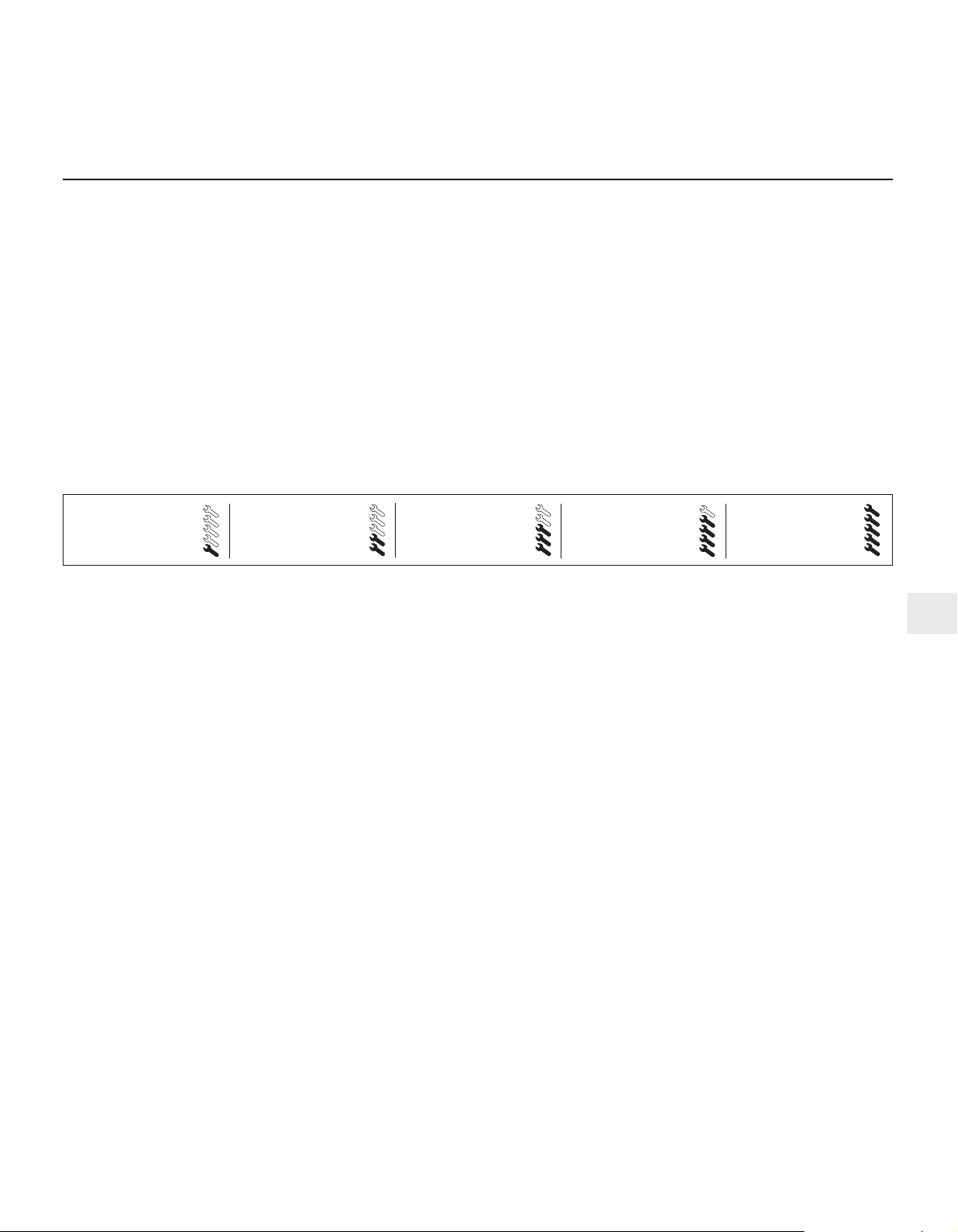
General
Maker’s designation . . . . . . . . . . . . . . . . . . . . . . . . . . . . . . . . . . . . . . . . 12 SC
Bore x stroke . . . . . . . . . . . . . . . . . . . . . . . . . . . . . . . . . . . . . . . . . . . . . 79.0 x 61.0 mm
Cubic capacity . . . . . . . . . . . . . . . . . . . . . . . . . . . . . . . . . . . . . . . . . . . . 1196 cc
Compression ratio . . . . . . . . . . . . . . . . . . . . . . . . . . . . . . . . . . . . . . . . . 9.0: 1
Valve clearances (warm)
Inlet . . . . . . . . . . . . . . . . . . . . . . . . . . . . . . . . . . . . . . . . . . . . . . . . . . . . . 0.15 mm
Exhaust . . . . . . . . . . . . . . . . . . . . . . . . . . . . . . . . . . . . . . . . . . . . . . . . . . 0.25 mm
Cylinder head
Identification mark . . . . . . . . . . . . . . . . . . . . . . . . . . . . . . . . . . . . . . . . . E
Valve seat width:
Inlet . . . . . . . . . . . . . . . . . . . . . . . . . . . . . . . . . . . . . . . . . . . . . . . . . . . 1.25 to 1.50 mm
Exhaust . . . . . . . . . . . . . . . . . . . . . . . . . . . . . . . . . . . . . . . . . . . . . . . . 1.60 to 1.85 mm
Overall height . . . . . . . . . . . . . . . . . . . . . . . . . . . . . . . . . . . . . . . . . . . . . 81 ± 0.25 mm
Valves and guides Inlet Exhaust
Overall length . . . . . . . . . . . . . . . . . . . . . . . . . . . . . . . . . . . . . . . . . . . . . 99.3 mm 101.1 mm
Head diameter . . . . . . . . . . . . . . . . . . . . . . . . . . . . . . . . . . . . . . . . . . . . 32 mm 29 mm
Stem diameter (nominal, ± 0.005 mm):
Standard . . . . . . . . . . . . . . . . . . . . . . . . . . . . . . . . . . . . . . . . . . . . . . . 7.005 mm 6.995 mm
Oversize 1 . . . . . . . . . . . . . . . . . . . . . . . . . . . . . . . . . . . . . . . . . . . . . . 7.080 mm 7.060 mm
Oversize 2 . . . . . . . . . . . . . . . . . . . . . . . . . . . . . . . . . . . . . . . . . . . . . . 7.155 mm 7.1 35 mm
Oversize A . . . . . . . . . . . . . . . . . . . . . . . . . . . . . . . . . . . . . . . . . . . . . . 7.255 mm 7.235 mm
Valve guide bore (± 0.01 mm):
Standard . . . . . . . . . . . . . . . . . . . . . . . . . . . . . . . . . . . . . . . . . . . . . . . 7.035 mm
Oversize 1 . . . . . . . . . . . . . . . . . . . . . . . . . . . . . . . . . . . . . . . . . . . . . . 7.110 mm
Oversize 2 . . . . . . . . . . . . . . . . . . . . . . . . . . . . . . . . . . . . . . . . . . . . . . 7.185 mm
Oversize A . . . . . . . . . . . . . . . . . . . . . . . . . . . . . . . . . . . . . . . . . . . . . . 7.285 mm
Valve clearance in guide:
Inlet . . . . . . . . . . . . . . . . . . . . . . . . . . . . . . . . . . . . . . . . . . . . . . . . . . . 0.01 5 to 0.045 mm
Exhaust . . . . . . . . . . . . . . . . . . . . . . . . . . . . . . . . . . . . . . . . . . . . . . . . 0.035 to 0.065 mm
Sealing face angle . . . . . . . . . . . . . . . . . . . . . . . . . . . . . . . . . . . . . . . . . 44°
Chapter 2 Part A:
OHV engine
Ancillary components - removal and refitting . . . . . . . . . . . . . . . . . . . .6
Camshaft and tappets - removal and refitting . . . . . . . . . . . . . . . . . .18
Compression test - description and interpretation . . . . . . . . . . . . . . . .2
Crankshaft and main bearings - removal and refitting . . . . . . . . . . .20
Crankshaft rear oil seal - removal and refitting . . . . . . . . . . . . . . . . .19
Cylinder head - overhaul . . . . . . . . . . . . . . . . . . . . . . . . . . . . . . . . . . .9
Cylinder head - removal and refitting . . . . . . . . . . . . . . . . . . . . . . . . .8
Cylinder head and pistons - decarbonising . . . . . . . . . . . . . . . . . . . .10
Engine oil and filter - renewal . . . . . . . . . . . . . . . . . . . . .See Chapter 1
Engine oil level check . . . . . . . . . . . . . . . . . . . . . . .See Weekly checks
Engine - initial start-up after overhaul . . . . . . . . . . . . . . . . . . . . . . . .24
Engine - removal and refitting . . . . . . . . . . . . . . . . . . . . . . . . . . . . . .23
Engine components - examination and renovation . . . . . . . . . . . . . .21
Engine dismantling and reassembly - general . . . . . . . . . . . . . . . . . . .5
Engine lubrication system - general description . . . . . . . . . . . . . . . .22
Engine/transmission mountings - removal and refitting . . . . . . . . . .17
Flywheel - removal and refitting . . . . . . . . . . . . . . . . . . . . . . . . . . . .16
General description . . . . . . . . . . . . . . . . . . . . . . . . . . . . . . . . . . . . . . .1
General engine checks . . . . . . . . . . . . . . . . . . . . . . . . . .See Chapter 1
Oil pump - overhaul . . . . . . . . . . . . . . . . . . . . . . . . . . . . . . . . . . . . . .13
Oil pump - removal and refitting . . . . . . . . . . . . . . . . . . . . . . . . . . . .12
Operations possible with the engine in the car . . . . . . . . . . . . . . . . . .3
Operations requiring engine removal . . . . . . . . . . . . . . . . . . . . . . . . .4
Pistons and connecting rods - removal and refitting . . . . . . . . . . . .15
Sump - removal and refitting . . . . . . . . . . . . . . . . . . . . . . . . . . . . . . .11
Timing gear components - removal and refitting . . . . . . . . . . . . . . .14
Valve clearances - adjustment . . . . . . . . . . . . . . . . . . . . . . . . . . . . . .7
2A•1
Easy, suitable for
novice with little
experience
Fairly easy, suitable
for beginner with
some experience
Fairly difficult,
suitable for competent
DIY mechanic
Difficult, suitable for
experienced DIY
mechanic
Very difficult,
suitable for expert
DIY or professional
Degrees of difficulty
Specifications
Contents
2A
Page 21

2A•2 OHV engine
Camshaft
Radial run-out . . . . . . . . . . . . . . . . . . . . . . . . . . . . . . . . . . . . . . . . . . . . . 0.03 mm max
Endfloat . . . . . . . . . . . . . . . . . . . . . . . . . . . . . . . . . . . . . . . . . . . . . . . . . . 0.17 to 0.43 mm
Cam lift . . . . . . . . . . . . . . . . . . . . . . . . . . . . . . . . . . . . . . . . . . . . . . . . . . 6.45 mm
Pistons and bores Diameters Marking
Production size 1 . . . . . . . . . . . . . . . . . . . . . . . . . . . . . . . . . . . . . . . . . . 78.95 mm 5
78.96 mm 6
78.97 mm 7
78.98 mm 8
Production size 2 . . . . . . . . . . . . . . . . . . . . . . . . . . . . . . . . . . . . . . . . . . 78.99 mm 99
79.00 mm 00
79.01 mm 01
79.02 mm 02
Production size 3 . . . . . . . . . . . . . . . . . . . . . . . . . . . . . . . . . . . . . . . . . . 79.03 mm 03
79.04 mm 04
79.05 mm 05
79.06 mm 06
Production size 4 . . . . . . . . . . . . . . . . . . . . . . . . . . . . . . . . . . . . . . . . . . 79.07 mm 07
79.08 mm 08
79.09 mm 09
79.10 mm 1
Oversize (+0.5 mm nominal) . . . . . . . . . . . . . . . . . . . . . . . . . . . . . . . . . . 79.47 mm 79.47/7 +0.5
79.48 mm 79.48/8 +0.5
79.49 mm 79.49/9 +0.5
79.50 mm 79.50/0 + 0.5
Pistons clearance in bore . . . . . . . . . . . . . . . . . . . . . . . . . . . . . . . . . . . . 0.1 to 0.3 mm estimated
Bore out-of-round and taper . . . . . . . . . . . . . . . . . . . . . . . . . . . . . . . . . 0.013 mm max
Piston rings
Quantity (per piston) . . . . . . . . . . . . . . . . . . . . . . . . . . . . . . . . . . . . . . . . 2 compression, 1 oil control (scraper)
Thickness:
Compression . . . . . . . . . . . . . . . . . . . . . . . . . . . . . . . . . . . . . . . . . . . . 2.0 mm
Oil control . . . . . . . . . . . . . . . . . . . . . . . . . . . . . . . . . . . . . . . . . . . . . . 5.0 mm
End gap:
Compression . . . . . . . . . . . . . . . . . . . . . . . . . . . . . . . . . . . . . . . . . . . . 0.30 to 0.45 mm
Oil control . . . . . . . . . . . . . . . . . . . . . . . . . . . . . . . . . . . . . . . . . . . . . . 0.40 to 1.40 mm
Ring gap offset . . . . . . . . . . . . . . . . . . . . . . . . . . . . . . . . . . . . . . . . . . . . 180° (see text)
Ring vertical clearance in groove . . . . . . . . . . . . . . . . . . . . . . . . . . . . . . Not specified - typically 0.06 mm
Gudgeon pins
Length . . . . . . . . . . . . . . . . . . . . . . . . . . . . . . . . . . . . . . . . . . . . . . . . . . . 65 mm
Diameter . . . . . . . . . . . . . . . . . . . . . . . . . . . . . . . . . . . . . . . . . . . . . . . . . 20 mm
Clearance in piston . . . . . . . . . . . . . . . . . . . . . . . . . . . . . . . . . . . . . . . . . 0.0015 to 0.0195 mm
Clearance in connecting rod . . . . . . . . . . . . . . . . . . . . . . . . . . . . . . . . . . None (interference fit)
Crankshaft and bearings
Number of main bearings . . . . . . . . . . . . . . . . . . . . . . . . . . . . . . . . . . . . 3
Main bearing journal diameters - standard:
Front . . . . . . . . . . . . . . . . . . . . . . . . . . . . . . . . . . . . . . . . . . . . . . . . . . 53.997 to 54.010 mm
Centre and rear . . . . . . . . . . . . . . . . . . . . . . . . . . . . . . . . . . . . . . . . . . 54.007 to 54.020 mm
Centre journal width - standard . . . . . . . . . . . . . . . . . . . . . . . . . . . . . . . 29.000 to 29.052 mm
Main bearing shell identification - standard: Colour code Embossed code
Front, top . . . . . . . . . . . . . . . . . . . . . . . . . . . . . . . . . . . . . . . . . . . . . . Brown 1 ON or 701-N
Front, bottom . . . . . . . . . . . . . . . . . . . . . . . . . . . . . . . . . . . . . . . . . . . Brown 1 UN or 702-N
Centre, top . . . . . . . . . . . . . . . . . . . . . . . . . . . . . . . . . . . . . . . . . . . . . Brown 20+UN or 705-N
Centre, bottom . . . . . . . . . . . . . . . . . . . . . . . . . . . . . . . . . . . . . . . . . . Green 20+UN or 725-N
Rear, top . . . . . . . . . . . . . . . . . . . . . . . . . . . . . . . . . . . . . . . . . . . . . . . Green 631-N
Rear, bottom . . . . . . . . . . . . . . . . . . . . . . . . . . . . . . . . . . . . . . . . . . . . Green 635-N
Main bearing shell identification - standard journal, oversize housing:
Front, top . . . . . . . . . . . . . . . . . . . . . . . . . . . . . . . . . . . . . . . . . . . . . . U1 -OB
Front, bottom . . . . . . . . . . . . . . . . . . . . . . . . . . . . . . . . . . . . . . . . . . . U1-U
Centre, top and bottom . . . . . . . . . . . . . . . . . . . . . . . . . . . . . . . . . . . U
Rear, top . . . . . . . . . . . . . . . . . . . . . . . . . . . . . . . . . . . . . . . . . . . . . . . U3-OB
Rear, bottom . . . . . . . . . . . . . . . . . . . . . . . . . . . . . . . . . . . . . . . . . . . . U3-U
Big-end bearing journal diameter - standard . . . . . . . . . . . . . . . . . . . . . 4.971 to 44.987 mm
Big-end bearing shell identification - standard . . . . . . . . . . . . . . . . . . . . None
Main and big-end bearing undersizes . . . . . . . . . . . . . . . . . . . . . . . . . . 0.25 mm production and service; 0.50 mm service only
Page 22

The engine is of four-cylinder. in-line
overhead valve type, mounted transversely at
the front of the car.
The crankshaft is supported in three shell
type main bearings. Thrustwashers are
incorporated in the centre main bearing to
control crankshaft endfloat.
The connecting rods are attached to the
crankshaft by horizontally split shell type
big-end bearings. and to the pistons by
gudgeon pins which are an interference fit in
the connecting rod small-end bore. The
aluminium alloy pistons are of the slipper type
and are fitted with three piston rings: two
compression rings and an oil control ring.
The camshaft is chain driven from the
crankshaft and operates the rocker arms via
1 General description
OHV engine 2A•3
2A
Main bearing shell identification - 0.25 undersize: Colour code Embossed code
Front, top . . . . . . . . . . . . . . . . . . . . . . . . . . . . . . . . . . . . . . . . . . . . . . Brown-blue 1 OA or 006-A
Front, bottom . . . . . . . . . . . . . . . . . . . . . . . . . . . . . . . . . . . . . . . . . . . Brown-blue 1 UA or 008-A
Centre, top . . . . . . . . . . . . . . . . . . . . . . . . . . . . . . . . . . . . . . . . . . . . . Brown-blue 20+UA or 014-A
Centre, bottom . . . . . . . . . . . . . . . . . . . . . . . . . . . . . . . . . . . . . . . . . . Brown 20+UA or 034-A
Rear, top . . . . . . . . . . . . . . . . . . . . . . . . . . . . . . . . . . . . . . . . . . . . . . . Green-blue 632-A
Rear, bottom . . . . . . . . . . . . . . . . . . . . . . . . . . . . . . . . . . . . . . . . . . . . Green-blue 636-A
Main bearing shell identification - 0.50 undersize:
Front, top . . . . . . . . . . . . . . . . . . . . . . . . . . . . . . . . . . . . . . . . . . . . . . Brown-black 1 OB or 027 B
Front, bottom . . . . . . . . . . . . . . . . . . . . . . . . . . . . . . . . . . . . . . . . . . . Brown-black 1 U or 029 B
Centre, top . . . . . . . . . . . . . . . . . . . . . . . . . . . . . . . . . . . . . . . . . . . . . Brown-black 2 OB 0.35 B
Centre, bottom . . . . . . . . . . . . . . . . . . . . . . . . . . . . . . . . . . . . . . . . . . Green-black 2 UB 035 B
Rear, top . . . . . . . . . . . . . . . . . . . . . . . . . . . . . . . . . . . . . . . . . . . . . . . None 3 OB 0,50
Rear, bottom . . . . . . . . . . . . . . . . . . . . . . . . . . . . . . . . . . . . . . . . . . . . None 3 U 0,50
Big-end bearing shell identification:
0.25 undersize . . . . . . . . . . . . . . . . . . . . . . . . . . . . . . . . . . . . . . . . . . . A
0.50 undersize . . . . . . . . . . . . . . . . . . . . . . . . . . . . . . . . . . . . . . . . . . . B
Main and big-end bearing journal out-of-round . . . . . . . . . . . . . . . . . . . 0.006 mm max
Main and big-end bearing journal taper . . . . . . . . . . . . . . . . . . . . . . . . . 0.01 mm max
Crankshaft endfloat . . . . . . . . . . . . . . . . . . . . . . . . . . . . . . . . . . . . . . . . 0.09 to 0.20 mm
Connecting rod endfloat . . . . . . . . . . . . . . . . . . . . . . . . . . . . . . . . . . . . . 0.02 to 0.06 mm
Main bearing running clearance:
Front . . . . . . . . . . . . . . . . . . . . . . . . . . . . . . . . . . . . . . . . . . . . . . . . . . 0.020 to 0.046 mm
Centre . . . . . . . . . . . . . . . . . . . . . . . . . . . . . . . . . . . . . . . . . . . . . . . . . 0.010 to 0.036 mm
Rear . . . . . . . . . . . . . . . . . . . . . . . . . . . . . . . . . . . . . . . . . . . . . . . . . . . 0.01 0 to 0.032 mm estimated
Big-end bearing running clearance . . . . . . . . . . . . . . . . . . . . . . . . . . . . 0.11 to 0.24 mm
Crankshaft radial run-out (at centre journal, shaft in block) . . . . . . . . . . 0.03 mm max
Flywheel
Ring gear run-out . . . . . . . . . . . . . . . . . . . . . . . . . . . . . . . . . . . . . . . . . . 0.5 mm max
Refinishing limit - depth of material which may be removed from
clutch friction surface . . . . . . . . . . . . . . . . . . . . . . . . . . . . . . . . . . . . . 0.3 mm max
Lubrication system
Oil pump tolerances:
Teeth backlash . . . . . . . . . . . . . . . . . . . . . . . . . . . . . . . . . . . . . . . . . . 0.1 to 0.2 mm
Teeth projection . . . . . . . . . . . . . . . . . . . . . . . . . . . . . . . . . . . . . . . . . 0.04 to 0.10 mm
Oil pressure at idle (engine warm) . . . . . . . . . . . . . . . . . . . . . . . . . . . . . 1.5 bar
Torque wrench settings Nm lbf ft
Flywheel bolts (Use new bolts every time):
Stage 1 . . . . . . . . . . . . . . . . . . . . . . . . . . . . . . . . . . . . . . . . . . . . . . . . 35 26
Stage 2 . . . . . . . . . . . . . . . . . . . . . . . . . . . . . . . . . . . . . . . . . . . . . . . . Angle-tighten a further 50° to 90°
Main bearing caps . . . . . . . . . . . . . . . . . . . . . . . . . . . . . . . . . . . . . . . . . 62 46
Big-end bearing caps . . . . . . . . . . . . . . . . . . . . . . . . . . . . . . . . . . . . . . . 27 20
Sump bolts (with locking compound) . . . . . . . . . . . . . . . . . . . . . . . . . . . 5 4
Cylinder head bolts (use new bolts every time):
Stage 1 . . . . . . . . . . . . . . . . . . . . . . . . . . . . . . . . . . . . . . . . . . . . . . . . 25 18
Stage 2 . . . . . . . . . . . . . . . . . . . . . . . . . . . . . . . . . . . . . . . . . . . . . . . . Angle-tighten a further 60°
Stage 3 . . . . . . . . . . . . . . . . . . . . . . . . . . . . . . . . . . . . . . . . . . . . . . . . Angle-tighten a further 60°
Stage 4 . . . . . . . . . . . . . . . . . . . . . . . . . . . . . . . . . . . . . . . . . . . . . . . . Angle-tighten a further 60°
Camshaft sprocket . . . . . . . . . . . . . . . . . . . . . . . . . . . . . . . . . . . . . . . . . 40 30
Crankshaft pulley . . . . . . . . . . . . . . . . . . . . . . . . . . . . . . . . . . . . . . . . . . 40 30
Engine mounting bracket, RH:
To block (use sealant on lower bolt) . . . . . . . . . . . . . . . . . . . . . . . . . . 20 15
To damping pad . . . . . . . . . . . . . . . . . . . . . . . . . . . . . . . . . . . . . . . . . 40 30
Engine mountings to body:
LH rear . . . . . . . . . . . . . . . . . . . . . . . . . . . . . . . . . . . . . . . . . . . . . . . . 65 48
RH rear . . . . . . . . . . . . . . . . . . . . . . . . . . . . . . . . . . . . . . . . . . . . . . . . 40 30
Sump drain plug . . . . . . . . . . . . . . . . . . . . . . . . . . . . . . . . . . . . . . . . . . . 45 33
Oil pump mounting bolts . . . . . . . . . . . . . . . . . . . . . . . . . . . . . . . . . . . . 20 15
Page 23

tappets and short pushrods. The inlet and
exhaust valves are each closed by a single
valve spring and operates in guides, integral
with the cylinder head. The valves are
actuated directly by the rocker arms.
Engine lubrication is by a gear type oil
pump. The pump is mounted beneath the
crankcase and is driven by a camshaft, as are
the distributor and fuel pump.
Many of the engine component retaining
bolts are of the socket-headed type and
require the use of Torx type multi-tooth keys
or socket bits for removal. These are readily
available from retail outlets and should be
obtained if major dismantling or repair work is
to be carried out on the engine.
1 When engine performance is down, or if
misfiring occurs which cannot be attributed to
the ignition or fuel systems, a compression
test can provide diagnostic clues as to the
engine’s condition. If the test is performed
regularly, it can give warning of trouble before
any other symptoms become apparent.
2 The engine must be fully warmed-up to
normal operating temperature, the battery
must be fully charged, and all the spark plugs
must be removed (Chapter 1). The aid of an
assistant will also be required.
3 Disable the ignition system by
disconnecting the ignition HT coil lead from
the distributor cap and earthing it on the
cylinder block. Use a jumper lead or similar
wire to make a good connection.
4 Fit a compression tester to the No 1
cylinder spark plug hole - the type of tester
which screws into the plug thread is best.
5 Have the assistant hold the throttle wide
open, and crank the engine on the starter
motor; after one or two revolutions, the
compression pressure should build up to a
maximum figure, and then stabilise. Record
the highest reading obtained.
6 Repeat the test on the remaining cylinders,
recording the pressure in each.
7 All cylinders should produce very similar
pressures; a difference of more than 2 bars
between any two cylinders indicates a fault.
Note that the compression should build up
quickly in a healthy engine; low compression
on the first stroke, followed by graduallyincreasing pressure on successive strokes,
indicates worn piston rings. A low
compression reading on the first stroke, which
does not build up during successive strokes,
indicates leaking valves or a blown head
gasket (a cracked head could also be the
cause). Deposits on the undersides of the
valve heads can also cause low compression.
8 Although Vauxhall do not specify exact
compression pressures, as a guide, any
cylinder pressure of below 10 bars can be
considered as less than healthy. Refer to a
Vauxhall dealer or other specialist if in doubt
as to whether a particular pressure reading is
acceptable.
9 If the pressure in any cylinder is low, carry
out the following test to isolate the cause. Put
a teaspoonfull of clean oil into that cylinder
through its spark plug hole, and repeat the
test.
10 If the addition of oil temporarily improves
the compression pressure, this indicates that
bore or piston wear is responsible for the
pressure loss. No improvement suggests that
leaking or burnt valves, or a blown head
gasket, may be to blame.
11 A low reading from two adjacent cylinders
is almost certainly due to the head gasket
having blown between them; the presence of
coolant in the engine oil will confirm this.
12 If one cylinder is about 20 percent lower
than the others and the engine has a slightly
rough idle, a worn camshaft lobe could be the
cause.
13 If the compression reading is unusually
high, the combustion chambers are probably
coated with carbon deposits. If this is the
case, the cylinder head should be removed
and decarbonised.
14 On completion of the test, refit the spark
plugs and reconnect the ignition system.
The following operations may be carried out
without having to remove the engine:
a) Adjustment of the valve clearances.
b) Removal and refitting of cylinder head.
c) Removal and refitting of sump.
d) Removal and refitting of oil pump.
e) Removal and refitting of the timing gear
components.
f) Removal and refitting of pistons and
connecting rods.
g) Removal and refitting of the flywheel.
h) Removal and refitting of the
engine/transmission mountings.
The following operations can only be
carried out after removal of the engine:
a) Removal and refitting of the camshaft and
tappets.
b) Removal and refitting of the crankshaft
and main bearings.
c) Removal and refitting of the crankshaft
rear oil seal.
1 If the engine has been removed from the
car for major overhaul, or if individual
components have been removed for repair or
renewal, observe the following general hints
on dismantling and reassembly.
2 Drain the oil into a suitable container and
then thoroughly clean the exterior of the
engine using a degreasing solvent or paraffin.
Clean away as much of the external dirt and
grease as possible before dismantling.
3 As parts are removed, clean them in a
paraffin bath. However, do not immerse parts
with internal oilways in paraffin as it is difficult
to remove, usually requiring a high pressure
hose. Clean oilways with nylon pipe cleaners.
4 Avoid working with the engine or any of the
components directly on a concrete floor, as
grit presents a real source of trouble.
5 Wherever possible, work should be carried
out with the engine or individual components
on a strong bench. If the work must be done
on the floor, cover it with a board or sheets of
newspaper.
6 Have plenty of clean, lint-free rags available
and also some containers or trays to hold
small items. This will help during reassembly
and also prevent possible losses.
7 Always obtain a complete set of gaskets if
the engine is being completely dismantled, or
all those necessary for the individual
component or assembly being worked on.
Keep the old gaskets with a view to using
them as a pattern to make a replacement if a
new one is not available.
8 If possible refit nuts, bolts and washers in their
locations after removal; this helps to protect the
threads and avoids confusion or loss.
9 During reassembly thoroughly lubricate all
the components, where this is applicable, with
engine oil, but avoid contaminating the
gaskets and joint mating faces.
10 Where applicable, the following Sections
describe the removal, refitting and adjustment
of components with the engine in the car. If
the engine has been removed from the car,
the procedures described are the same
except for the disconnection of hoses, cables
and linkages, and the removal of components
necessary for access, which will already have
been done.
If the engine has been removed from the
car for complete dismantling, the following
externally mounted ancillary components
should be removed. When the engine has
been reassembled these components can be
refitted before the engine is installed in the
car, as setting up and adjustment is often
easier with the engine removed. The removal
and refitting sequence need not necessarily
follow the order given:
a) Alternator (Chapter 5A).
b) Distributor and spark plugs (Chapters 1
and 5).
c) Inlet and exhaust manifolds and
carburettor (Chapter 4A).
d) Fuel pump (Chapter 4A).
e) Water pump and thermostat (Chapter 3).
f) Clutch assembly (Chapter 6).
6 Ancillary components - removal
and refitting
5 Engine dismantling and
reassembly - general information
4 Operations requiring engine
removal
3 Operations possible with the
engine in the car
2 Compression test - description
and interpretation
2A•4 OHV engine
Page 24
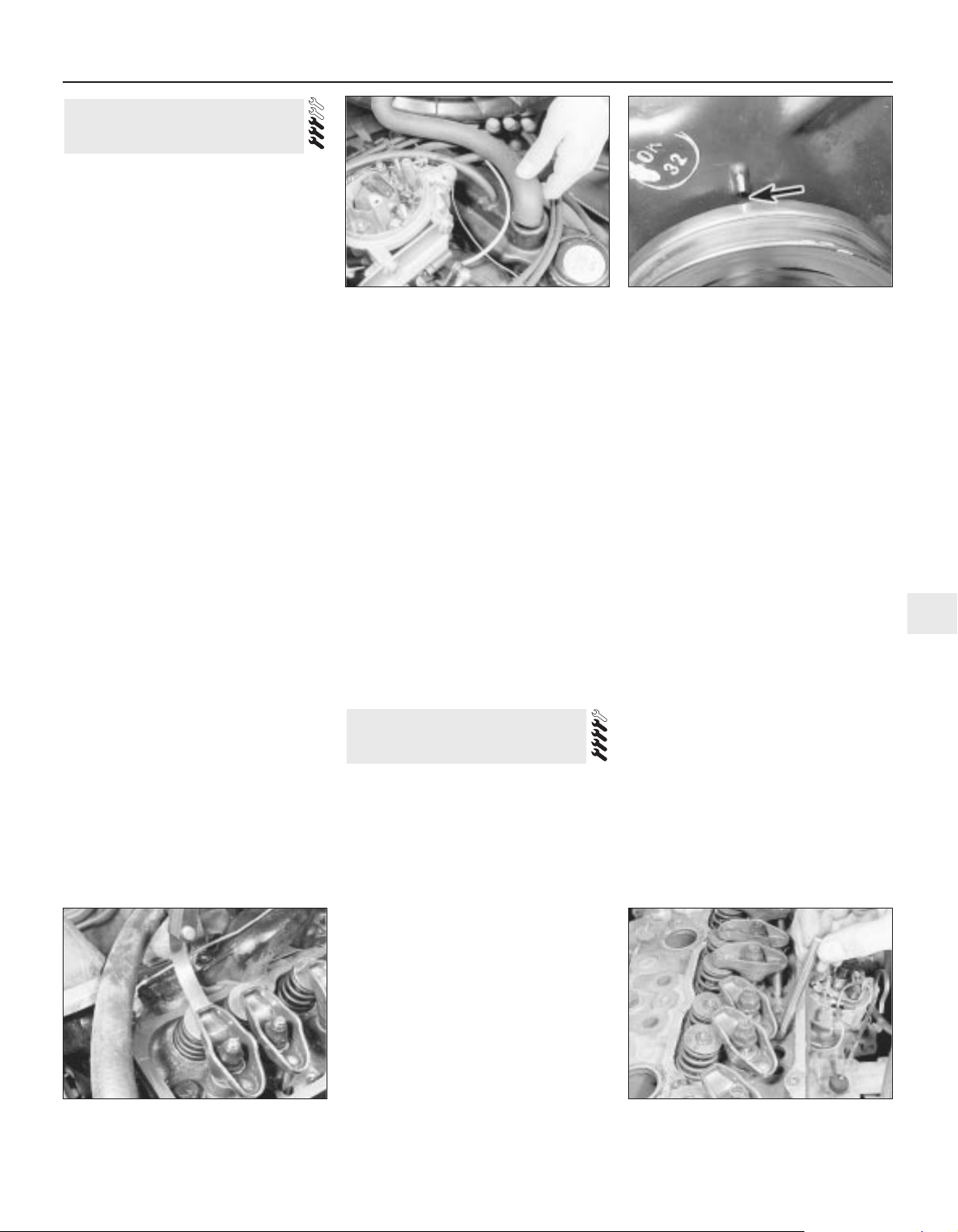
1 This adjustment should be carried out with
the engine at its normal operating
temperature. If it is being done after overhaul
when the engine is cold, repeat the
adjustment after the car has been driven a few
kilometres when the engine will then be hot.
2 Begin by removing the air cleaner, as
described in Chapter 4A.
3 Mark the spark plug leads to ensure correct
refitting and then pull them off the spark
plugs.
4 Disconnect the engine breather hoses at
the rocker cover (see illustration).
5 Undo the four bolts securing the rocker
cover to the cylinder head and lift off the
shaped spreader washers.
6 Withdraw the rocker cover from the cylinder
head. If it is stuck give it a tap with the palm of
your hand to free it.
7 Turn the engine by means of the crankshaft
pulley bolt, or by engaging top gear and
pulling the car forward, until No 1 piston is
approaching TDC on the firing stroke. This
can be checked by removing No 1 spark plug
and feeling for compression with your fingers
as the engine is turned, or by removing the
distributor cap and checking the position of
the rotor arm which should be pointing to the
No 1 spark plug lead segment in the cap. The
ignition timing marks on the pulley and timing
cover must be aligned (see illustration).
8 With the engine in this position the
following valves can be adjusted - counting
from the timing cover end of the engine.
1 exhaust
2 inlet
3 inlet
5 exhaust
9 Now turn the engine crankshaft through
one complete revolution and adjust the
following remaining valves:
4 exhaust
6 inlet
7 inlet
8 exhaust
10 As each clearance is being checked, slide
a feeler blade of the appropriate size, as given
in the Specifications, between the end of the
valve stem and the rocker arm (see
illustration). Adjust the clearance by turning
the rocker arm retaining nut using a socket or
ring spanner until the blade is a stiff sliding fit.
11 It is also possible to check and adjust the
clearances with the engine running. This is
done in the same way, but each valve is
checked in turn. It will of course be necessary
to refit the plug leads and No 1 spark plug if
this method is adopted. To reduce oil splash
place a piece of cardboard, suitably cut to
shape, between the pushrod side of the
rocker arms and the edge of the cylinder
head.
12 After adjustment remove all traces of old
gasket from the cylinder head mating face
and renew the rocker cover gasket if it is
cracked or perished.
13 Refit the rocker cover and secure with the
retaining bolts and shaped spreader washers.
14 Refit the spark plug and plug leads,
reconnect the engine breather hoses and refit
the air cleaner, as described in Chapters 1
and 4.
Removal
1 Make sure that the engine is cold before
commencing operations to avoid any chance
of the head distorting.
2 Disconnect the battery negative terminal
3 Drain the cooling system, as described in
Chapter 1, and remove the air cleaner, as
described in Chapter 4A.
4 From behind the engine, undo the two bolts
securing the exhaust front pipe to the
manifold. Remove the bolts and tension
springs; then separate the pipe joint from the
manifold.
5 Slacken the retaining clip and disconnect
the radiator top hose from the thermostat
housing in the water pump.
6 Slacken the alternator mounting and
adjustment arm bolts, move the alternator
towards the engine and slip the drivebelt off
the pulleys.
7 Slacken the retaining clips and disconnect
the heater hose and radiator bottom hose
from the water pump.
8 Disconnect the other heater hose at the
cylinder head outlet after slackening the
retaining clip.
9 Undo the union nut and disconnect the
brake servo vacuum hose from the inlet
manifold.
10 Note the location of the plug leads to aid
refitting and pull them off the spark plugs.
Disconnect the HT lead at the coil, undo the
distributor cap retaining screws and remove
the cap and leads.
11 Refer to Chapter 4A and disconnect the
choke and accelerator cables from the
carburettor. Detach the distributor vacuum
advance pipe.
12 Disconnect the fuel hose from the
carburettor and plug its end after removal.
13 Disconnect the engine breather hoses
from the rocker cover.
14 Undo the three socket-headed screws
securing the inlet manifold to the cylinder
head. Note the spark plug lead support
brackets fitted to the two end retaining bolts.
15 Lift the inlet manifold complete with
carburettor from the cylinder head and
recover the gasket.
16 Undo the four bolts and shaped spreader
washers and lift off the rocker cover.
17 Slacken the rocker arm retaining nuts,
move the rocker arms to one side and lift out
the pushrods (see illustration). Keep the
pushrods in order after removal.
18 Undo the cylinder head retaining bolts,
half a turn at a time in the reverse sequence to
that shown in illustration 8.26. Unscrew the
bolts fully and remove them. Obtain new bolts
for use when refitting.
8 Cylinder head - removal and
refitting
7 Valve clearances - adjustment
OHV engine 2A•5
2A
7.7 Ignition timing marks (arrowed) in
alignment
8.17 Removing the pushrods7.10 Checking a valve clearance
7.4 Removing the breather hose from the
rocker cover
Page 25
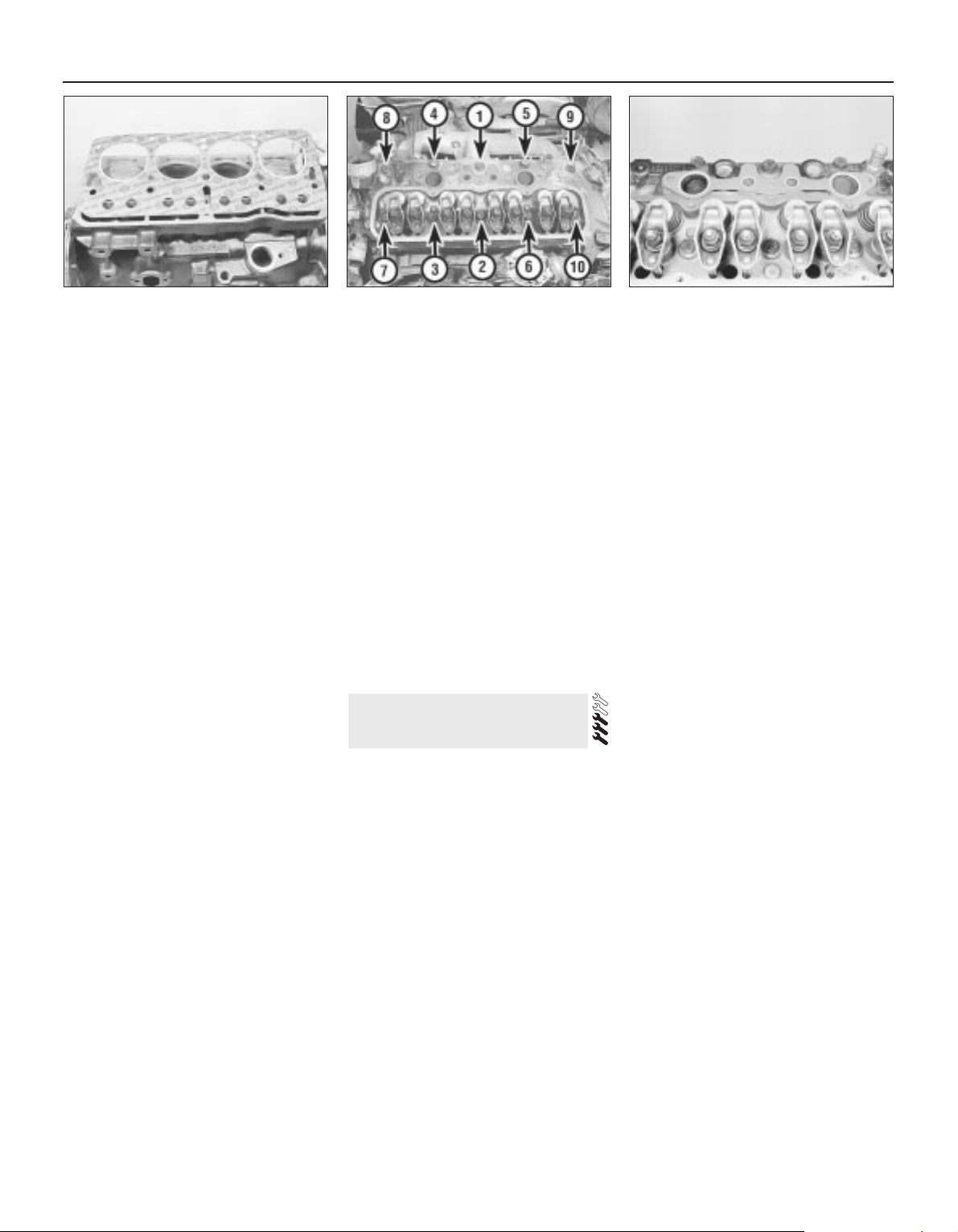
19 Lift the cylinder head from the block. If it is
stuck, tap it free with a soft-faced mallet. Do
not insert a lever into the gasket joint - you
may damage the mating surfaces.
20 With the cylinder head removed, recover
the gasket.
21 If the cylinder head has been removed for
decarbonising or for attention to the valves or
springs, reference should be made to
Sections 9 and 10.
Refitting
22 Before refitting the cylinder head, ensure
that the cylinder block and head mating faces
are spotlessly clean and dry with all traces of
old gasket removed. Use a scraper and wire
brush to do this, but take care to cover the
water passages and other openings with
masking tape or rag to prevent dirt and
carbon falling in. Remove all traces of oil and
water from the bolt holes, otherwise hydraulic
pressure created by the bolts being screwed
in could crack the block or give inaccurate
torque settings. Ensure that the bolt threads
are clean and dry.
23 When all is clean, screw two guide studs
into the cylinder block. These can be made
from the two old cylinder head bolts by
cutting off their heads and sawing a
screwdriver slot in their ends.
24 Locate a new gasket in position on the
block as shown (see illustration). Do not use
any jointing compound on the gasket
25 Lower the cylinder head carefully into
position. Screw in new bolts finger tight,
remove the guide pins and screw in the two
remaining bolts.
26 Tighten the cylinder head bolts in the
order shown (see illustration) to the first
stage specified torque. Now tighten the bolts
through three further stages as given in the
Specifications. No further retightening will be
required.
27 Refit the pushrods, making quite sure that
each one is located in its tappet.
28 Reposition the rocker arms over the ends
of the pushrods and then adjust the valve
clearances, as described in Section 7.
29 Place a new gasket in position and refit
the inlet manifold and carburettor (see
illustration).
30 Refit the rocker cover, using a new
gasket, and secure with the four bolts and
spreader washers.
31 Refit the heater hoses and radiator hoses
to the outlets on the water pump and cylinder
head.
32 Refit the fuel hose to the carburettor, the
vacuum advance pipe to the distributor and
the breather hoses to the rocker cover.
33 Refit and adjust the accelerator and choke
cables, as described in Chapter 4A.
34 Refit the brake servo vacuum hose to the
inlet manifold.
35 Refit the distributor cap and reconnect the
plug leads and coil lead.
36 Slip the drivebelt over the pulleys and
adjust its tension, as described in Chapter 1.
37 Reconnect the exhaust front pipe to the
manifold and tighten the bolts to compress
the tension springs.
38 Refill the cooling system as described in
Chapter 1, refit the air cleaner as described in
Chapter 4A and connect the battery negative
terminal.
1 Unscrew the rocker arm retaining
/adjustment nuts and withdraw the rocker
arms from the studs. Keep them in order as
they are removed.
2 To remove the valves, the springs will have
to be compressed to allow the split collets to
be released from the groove in the upper
section of the valve stems. A valve spring
compressor will therefore be necessary.
3 Locate the compressor to enable the forked
end of the arm to be positioned over the valve
spring collar whilst the screw part of the
clamp is situated squarely on the face of the
valve.
4 Screw up the clamp to compress the spring
and release the pressure of the collar acting
on the collets. If the collar sticks, support the
head and clamp frame and give the end of the
clamp a light tap with a hammer to help
release it.
5 Extract the two collets and then release the
tension of the clamp. Remove the clamp,
withdraw the collar and spring and extract the
valve. Remove the valve stem seals and the
exhaust valve rotators.
6 As they are released and removed, keep
the valves in order so that if they are to be
refitted they will be replaced in their original
positions in the cylinder head. A piece of stiff
card with eight holes punched in it is a sure
method of keeping the valves in order.
7 Examine the head of the valves for pitting
and burning, especially the heads of the
exhaust valves. The valve seating should be
examined at the same time. If the pitting on
valve and seat is very slight, the marks can be
removed by grinding the seats and valves
together with coarse, and then fine, valve
grinding paste.
8 Where bad pitting has occurred to the valve
seats it will be necessary to recut them and fit
new valves. The latter job should be entrusted
to the local agent or engineering works. In
practice it is very seldom that the seats are so
badly worn. Normally it is the valve that is too
badly worn for refitting, and the owner can
easily purchase a new set of valves and
match them to the seats by valve grinding.
9 Valve grinding is carried out as follows.
Smear a trace of coarse carborundum paste
on the seat face and apply a suction grinder
tool to the valve head. With a semi-rotary
motion, grind the valve head to its seat, lifting
the valve occasionally to redistribute the
grinding paste. When a dull matt even surface
is produced on both the valve seat and the
valve, wipe off the paste and repeat the
process with fine carborundum paste, lifting
and turning the valve to redistribute the paste
as before. A light spring placed under the
valve head will greatly ease this operation.
When a smooth unbroken ring of light grey
matt finish is produced, on both valve and
valve seat faces, the grinding operation is
complete.
10 Scrape away all carbon from the valve
head and the valve stem. Carefully clean away
every trace of grinding compound; take great
care to leave none in the ports or in the valve
guides. Clean the valves and valve seats with
a paraffin-soaked rag, then with a clean rag
and finally, if an air line is available, blow the
valves, valve guides and valve ports clean.
11 Check that all valve springs are intact. If
any one is broken, all should be renewed.
Check the free height of the springs against
new ones. If some springs are not within
9 Cylinder head - overhaul
2A•6 OHV engine
8.24 Fitting a cylinder head gasket 8.29 Inlet manifold gasket in position8.26 Cylinder head bolt tightening
sequence
Page 26
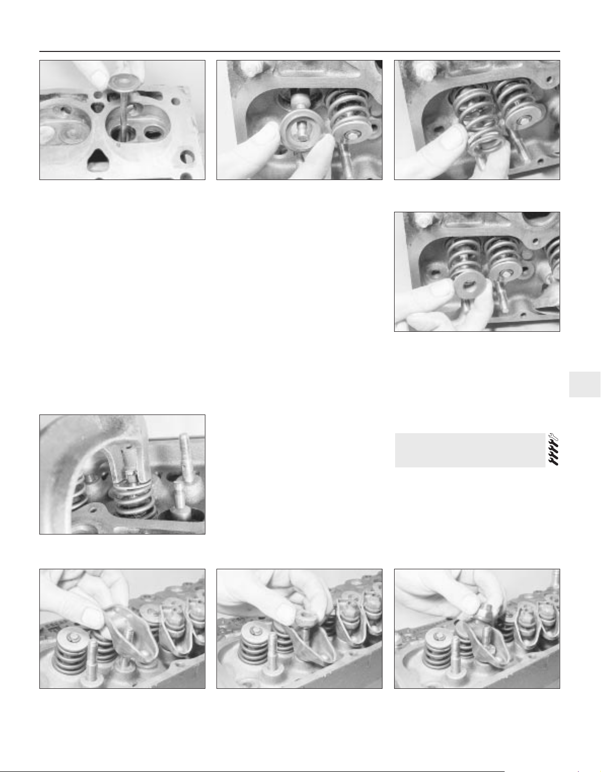
specification, replace them all. Springs suffer
from fatigue and it is a good idea to renew
them even if they look serviceable.
12 Check that the oil supply holes in the
rocker arm studs are clear.
13 The cylinder head can be checked for
warping either by placing it on a piece of plate
glass or using a straight-edge and feeler
blades. Slight distortion may be corrected by
having the head machined to remove metal
from the mating face.
14 Valve guide renewal is necessary if the
valve stem clearance in the guide exceeds
that specified. Renewal, or reaming to accept
oversize valves, should be left to a GM dealer.
15 Commence reassembly by lubricating a
valve stem and inserting it into its guide (see
illustration).
16 Fit the valve stem oil seal, using the
protective sleeve supplied with the new seals
over the valve stem to avoid damage.
Lubricate the sleeve and push on the seal,
ring downwards. Recover the sleeve.
17 On exhaust valves, fit the valve rotator
(see illustration).
18 Fit the valve spring and collar, with the
recessed part of the collar inside the spring
(see illustrations).
19 Place the end of the spring compressor
over the collar and valve stem and, with the
screw head of the compressor over the valve
head, screw up the clamp until the spring is
compressed past the groove in the valve
stem. Then put a little grease round the
groove.
20 Place the two halves of the split collar
(collets) into the groove with the narrow ends
pointing towards the spring (see illustration).
The grease will hold them in the groove.
21 Release the clamp slowly and carefully,
making sure that the collets are not dislodged
from the groove. When the clamp is fully
released the top edges of the collets should
be in line with each other. Give the top of each
spring a smart tap with a soft-faced mallet
when assembly is complete to ensure that the
collets are properly settled.
22 Repeat the above procedure for the other
7 valves.
23 The rocker gear can be refitted with the
head either on or off the engine. The only part
of the procedure to watch is that the rocker
nuts must not be screwed down too far or it
will not be possible to refit the pushrods.
24 Next put the rocker arm over the stud
followed by the pivot ball (see illustrations).
Make sure that the spring fits snugly round
the rocker arm centre section and that the two
bearing surfaces of the interior of the arm and
the ball face, are clean and lubricated with
engine oil.
25 Oil the stud thread and fit the nut with the
self-locking collar uppermost (see
illustration). Screw it down until the locking
collar is on the stud.
1 This can be carried out with the engine
either in or out of the car. With the cylinder
head removed, carefully use a wire brush and
blunt scraper to clean all traces of carbon
deposits from the combustion spaces and the
ports. The valve head stems and valve guides
should also be freed from any carbon
deposits. Wash the combustion spaces and
ports down with petrol and scrape the
cylinder head surface free of any foreign
10 Cylinder head and pistons
- decarbonising
OHV engine 2A•7
2A
9.18a Fit the valve spring . . .
9.25 Fit the nut with the self-locking collar
uppermost
9.24b . . . and its pivot ball9.24a Fitting a rocker arm . . .
9.20 Compress the spring and fit the
collets
9.18b . . . followed by the spring collar
9.17 Fitting an exhaust valve rotator9.15 Fitting a valve to its guide
Page 27
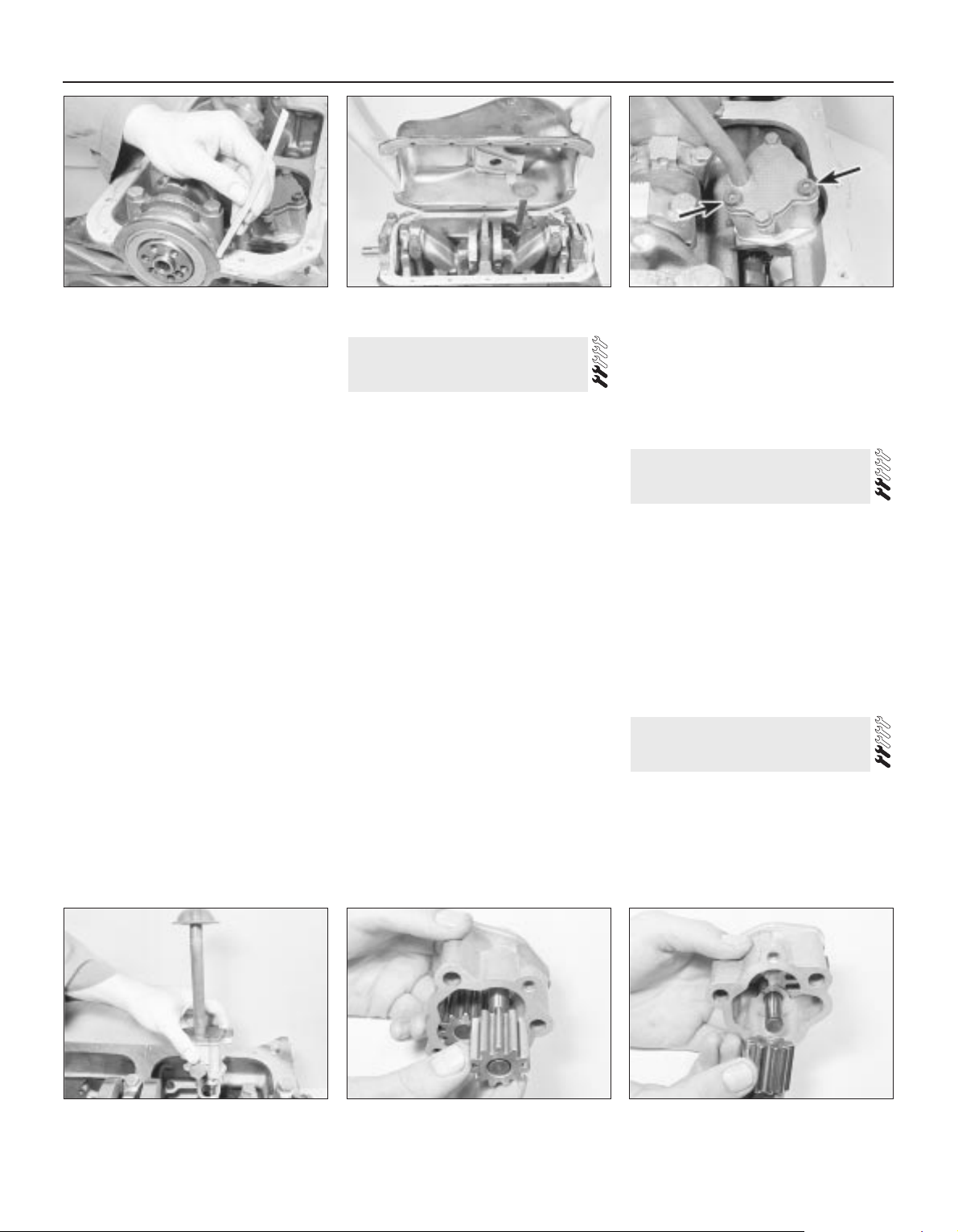
matter with the side of a steel rule or a similar
article.
2 If the engine is installed in the car, clean the
pistons and the top of the cylinder bores. If
the pistons are still in the block, then it is
essential that great care is taken to ensure
that no carbon gets into the cylinder bores as
this could scratch the cylinder walls or cause
damage to the piston and rings. To ensure
this does not happen, first turn the crankshaft
so that two of the pistons are at the top of
their bores. Stuff rag into the other two bores
or seal them off with paper and masking tape.
The waterways should also be covered with
small pieces of masking tape to prevent
particles of carbon entering the cooling
system and damaging the water pump.
3 Press a little grease into the gap between
the cylinder walls and the two pistons which
are to be worked on. With a blunt scraper
carefully scrape away the carbon from the
piston crown, taking great care not to scratch
the aluminium. Also scrape away the carbon
from the surrounding lip of the cylinder wall.
When all carbon has been removed, scrape
away the grease which will now be
contaminated with carbon particles, taking
care not to press any into the bores. To assist
prevention of carbon build-up the piston
crown can be polished with a metal polish.
Remove the rags or masking tape from the
other two cylinders and turn the crankshaft so
that the two pistons which were at the bottom
are now at the top. Place rag or masking tape
in the cylinders which have been
decarbonised and proceed as just described.
Decarbonising is now complete.
Removal
1 Jack up the front of the car and securely
support it on axle stands (see “Jacking and
Vehicle Support”).
2 Drain the engine oil into a suitable container
(Section 2) and refit the plug after draining.
3 Undo the bolts securing the flywheel cover
plate and side support braces and remove the
cover.
4 Undo the retaining bolts and lift away the
sump. It will probably be necessary to tap the
sump from side to side with a hide or plastic
mallet to release the joint face.
Refitting
5 Thoroughly clean the sump in paraffin or a
suitable solvent and remove all traces of
external dirt and internal sludge. Scrape away
all traces of old gasket from the sump and
crankcase faces and ensure that they are
clean and dry. Also clean the bearing cap
grooves.
6 Apply a thick bead of jointing compound to
the crankcase flange and at the joints of the
front and rear main bearing caps
7 Position the cork side gaskets on the
crankcase flanges and then insert the cork
and sealing strips to the main bearing cap
grooves (see illustration).
8 Apply a further bead of jointing compound
to the gasket faces and to the gasket joints at
the bearing caps.
9 Refit the sump (see illustration) and secure
it in place with the retaining bolts which
should be progressively tightened in a
diagonal sequence.
10 Refit the flywheel cover plate, lower the
car and fill the engine with oil as described in
Chapter 1.
Removal
1 Remove the sump. as described in Section
11.
2 Undo the two socket-headed bolts and
withdraw the pump from the crankcase (see
illustrations).
Refitting
3 Refitting the pump is the reverse sequence
to removal, but engage the pump shaft in the
distributor driveshaft slot, and tighten the
retaining bolts to the specified torque.
1 Remove the oil pump, as described in
Section 12.
2 Undo the two pump cover bolts and lift off
the cover and oil pick-up tube. Remove the
cover gasket.
3 Take out the driving gear and driven gear
(see illustrations).
13 Oil pump - overhaul
12 Oil pump - removal and
refitting
11 Sump - removal and refitting
2A•8 OHV engine
11.7 Insert the cork strips in the main
bearing cap grooves
12.2a Undo the two socket-headed bolts
(arrowed) . . .
13.3b . . . and the driven gear13.3a Removing the oil pump driving
gear . . .
12.2b . . . and remove the oil pump
11.9 Refitting the sump
Page 28
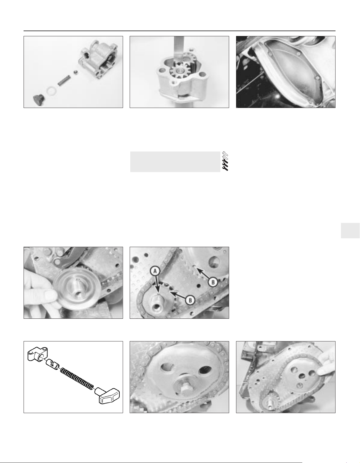
4 Undo the large nut on the side of the
housing and remove the sealing washer and
oil pressure relief spring and ball valve (see
illustration).
5 Clean all the parts in paraffin and dry with a
lint-free cloth.
6 Inspect the pump gears, housing, cover
and relief valve ball for scoring, scuff marks or
other signs of wear and renew the pump if
these signs are evident.
7 If the pump condition is satisfactory, check
the pump clearances as follows.
8 Using a feeler blade, check the backlash
between the gear teeth. Place a straight-edge
across the top edge of the gears and check
their projection. If any of the clearances
exceeds the tolerances given in the
Specifications, renew the pump (see
illustration).
9 If the clearances are satisfactory, refit the
relief valve assembly and assemble the pump
gears. Fill the pump with oil and refit the cover
using a new gasket. Tighten the cover
securing bolts and refit the pump.
Removal
1 For greater access remove the front
right-hand wheel trim and slacken the wheel
bolts. Jack up the front of the car, support it
securely on axle stands (see “Jacking and
Vehicle Support”) and remove the roadwheel.
2 Undo the four retaining bolts and remove
the clutch access plate at the base of the
bellhousing (see illustration).
3 Slacken the alternator mounting and
adjustment arm bolts, move the alternators
towards the engine and slip the drivebelt off
the pulleys.
4 Lock the flywheel by wedging a screwdriver
between the ring gear teeth and the side of
the bellhousing.
5 Using a socket or spanner undo the
crankshaft pulley retaining bolt and withdraw
the pulley.
6 Undo the bolts securing the timing cover to
the front of the engine and lift off the cover.
7 Withdraw the oil slinger from the
crankshaft, noting which way round it is fitted
(see illustration).
8 Temporarily refit the pulley and turn the
crankshaft until the crankshaft sprocket
keyway is uppermost and the timing marks on
the two sprockets are in alignment (see
illustration). Remove the pulley.
9 Undo the two retaining bolts and remove
the timing chain tensioner. One of two types
of tensioner may be fitted: simple
spring-operated, or oil pressure assisted. With
the oil pressure assisted type, restrain the
thrust pad to prevent premature ejection of
the tensioner components (see illustration).
10 Undo the camshaft sprocket retaining bolt
and remove the bolt and washer (see
illustration). Place a screwdriver through one
of the sprocket holes and in contact with the
camshaft retaining plate behind the sprocket
to stop it turning as the bolt is undone.
11 Withdraw the camshaft sprocket and
crankshaft sprocket from their respective
locations, using a screwdriver as a lever if
necessary, then remove the sprockets
complete with chain (see illustration).
12 Thoroughly clean all the components in
14 Timing gear components -
removal and refitting
OHV engine 2A•9
2A
14.2 Clutch access plate
14.11 Removing the sprockets and timing
chain
14.10 Camshaft sprocket retaining bolt
and washer
14.9 Timing chain tensioner - oil pressure
assisted type
14.7 Crankshaft oil slinger 14.8 Crankshaft sprocket keyway (A) and
sprocket timing marks (B)
13.8 Check the pump gear teeth backlash13.4 Oil pump and pressure relief valve
components
Page 29
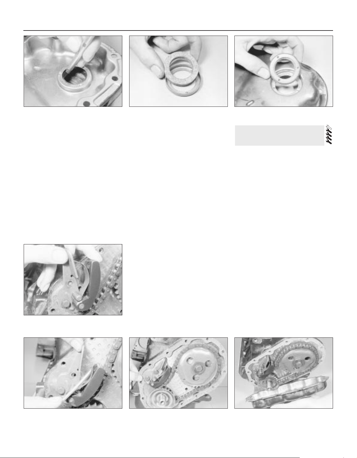
paraffin and dry them with a lint-free cloth.
Remove all traces of old gasket from the faces
of the timing cover and engine.
Refitting
13 To renew the oil seal in the timing cover,
place the cover outer face downwards over
two blocks of wood and drive out the old seal
and holder using a hammer and drift (see
illustration).
14 Place the new seal (which must have been
soaked in engine oil for 24 hours) in the holder
and then tap the holder into the cover using a
block of wood (see illustrations). The seal
holder must be fitted flush with the outer edge
of the timing cover.
15 Commence reassembly by engaging the
chain around the crankshaft sprocket.
16 Engage the camshaft sprocket within the
loop of the chain so that it can be fitted to the
camshaft and will have its timing mark in
alignment with the one on the crankshaft
sprocket. Adjust the camshaft sprocket as
necessary within the chain loop to achieve
this.
17 Fit the sprocket to the camshaft, screw in
the bolt and washer and tighten the bolt while
holding the sprocket with a screwdriver, as
was done during removal.
18 Refit the timing chain tensioner. With the
oil pressure assisted type, compress the
thrust pad by hand, secure the tensioner and
release the thrust pad.
19 To refit the spring-operated chain
tensioner, place the tensioner in position and
fit the lower retaining bolt finger tight. Move
the spring blade away from the tensioner
body with a screwdriver, pivot the tensioner
into position and fit the upper retaining bolt,
then release the springs and tighten both
bolts (see illustrations).
20 Position the oil slinger over the crankshaft
and place a new gasket on the front of the
engine (see illustration). Apply jointing
compound to both sides of the gasket.
21 Refit the cover and the retaining bolts, but
only screw the bolts in two or three turns (see
illustration). Position the crankshaft pulley on
the crankshaft to centralise the cover and
then tighten the bolts progressively in a
diagonal sequence.
22 Refit the pulley retaining bolt and tighten
to the specified torque.
23 Refit the drivebelt and adjust its tension,
as described in Chapter 1.
24 Refit the roadwheel and lower the car to
the ground. Tighten the wheel bolts.
Removal
1 Remove the cylinder head, the sump and
the oil pump, as described in earlier Sections.
2 The connecting rod big-end caps and rods
may not be marked numerically for location
when new and therefore they must be
inspected for identification marks before
dismantling. If no marks are evident, punch,
scribe or file identification marks on the caps
and rods starting with No 1 at the timing cover
end. Mark them all on the same side to avoid
confusion during reassembly. If they have
already been marked then this will not, of
course, be necessary.
3 Undo and remove the big-end cap retaining
bolts and keep them in order for correct
refitting.
4 Detach the big-end bearing caps. If stuck,
lightly tap them free using a soft-faced mallet.
5 To remove the bearing shells for inspection
and/or renewal, press the bearing end
opposite the groove in both connecting rod
and bearing cap and the shells will slide out.
Again keep the shells in order of removal.
6 The piston rod assemblies are removed
through the top of each cylinder bore, being
pushed upwards from underneath using a
wooden hammer handle which is pushed
against the connecting rod. Rotate the
crankshaft accordingly to gain suitable access
to each rod assembly. Note that, if there is a
pronounced wear ridge at the top of the
15 Pistons and connecting rods
- removal and refitting
2A•10 OHV engine
14.13 Using a drift to remove the timing
cover oil seal
14.14b . . . and refit the holder and seal to
the timing cover
14.21 Refitting the timing cover14.20 Fitting a new timing cover gasket14.19b . . . then push back the spring,
pivot the tensioner and fit the upper bolt
14.19a Fit the tensioner lower bolt . . .
14.14a Fit the new seal to the holder
Page 30
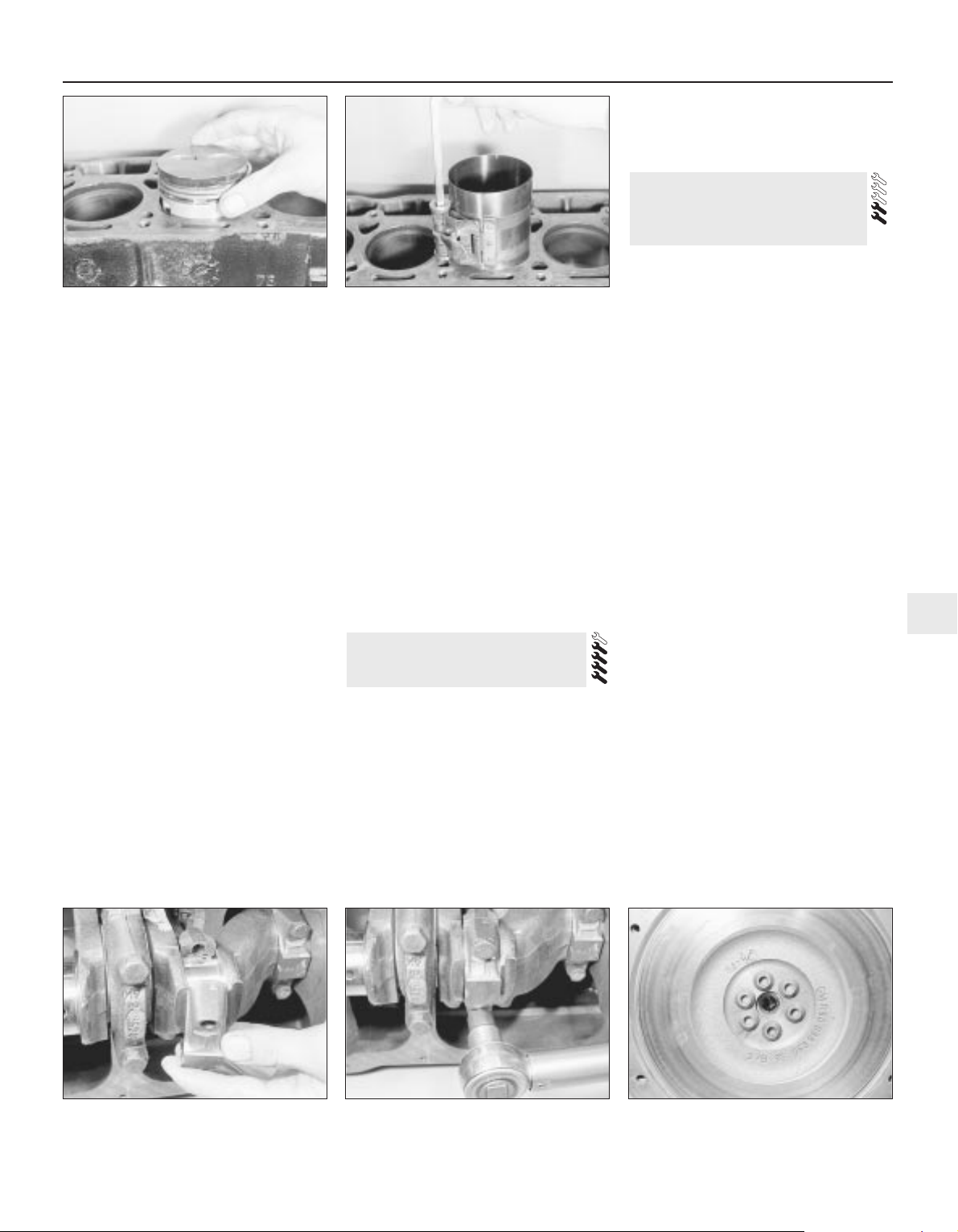
cylinder bore, there is a risk of piston ring
damage unless the ridge is first removed
using a ridge reaming tool, or scraper.
7 The pistons should not be separated from
their connecting rods unless they or the
gudgeon pins are to be renewed. The
gudgeon pin is a press fit and special tools
are required for removing and installation.
This task should therefore be entrusted to
your local agent or automotive machine shop.
8 If for any reason the pistons are separated
from their rods, mark them numerically on the
same side as the rod markings to ensure
correct refitting.
Refitting
9 If new pistons or piston rings are being
fitted to the old bores, it is essential to
roughen the cylinder bore walls slightly with
medium grit emery cloth to allow the rings to
bed in. Do this with a circular up-and-down
action to produce a criss-cross pattern on the
cylinder bore walls. Make sure that the
bearing journal on the crankshaft is protected
with masking tape during this operation.
Thoroughly clean the bores with a
paraffin-soaked rag and dry with a lint-free
cloth Remove the tape from the crankshaft
journals and clean them also.
10 Commence reassembly by lubricating the
cylinder bores and crankshaft journals.
11 Space the piston rings around the pistons
so that their end gaps are 180º apart. In the
case of the oil scraper ring, offset the gaps in
the upper and lower rails by 25 to 50 mm to
right and left of the end gap of the central
section. Offer a piston/connecting rod
assembly to its bore, making sure that it is the
right way round (see illustration).
12 Oil the piston and rings, then fit a piston
ring compressor to the piston and tighten it to
compress the rings (see illustration).
13 Gently tap the piston through the ring
compressor and into its bore using the
hammer handle. Guide the connecting rod
near to its crankshaft journal and then fit the
bearing shell upper half.
14 Ease the connecting rod onto the journal,
fit the lower shell to the cap and fit the cap to
the rod (see illustration). Refit and tighten the
retaining bolts to the specified torque (see
illustration).
15 Repeat the sequence described for the
remaining three piston/ connecting rods.
16 Refit the cylinder head, oil pump and
sump, as described in earlier Sections.
Removal
1 Remove the clutch assembly and the
release bearing, as described in Chapter 6.
2 Undo the three bolts and remove the
release bearing guide tube.
3 Mark the position of the flywheel in relation
to the crankshaft mounting flange or pulley.
4 Wedge a screwdriver between the ring gear
teeth and transmission casing and then undo
the socket-headed retaining bolts using a
multi-tooth key or socket bit (see illustration).
Remove the bolts and withdraw the flywheel.
Refitting
5 Refitting is the reverse sequence to
removal. Tighten the flywheel retaining bolts
to the specified torque.
Removal
1 The engine/transmission assembly is
supported in a triangular arrangement of three
mountings: one on the right-hand side
supporting the engine, one on the left-hand
side supporting the transmission and a third
centrally sited mount supporting the complete
assembly at the rear.
2 To remove either of the front mountings
position a jack under the engine or
transmission adjacent to the mounting and
just take the weight of the engine or
transmission.
3 Undo the bolts securing the support
bracket to the engine or gearbox and the bolts
securing the mounting to the bodyframe. Lift
off the bracket and remove the relevant
mounting.
4 To remove the rear mounting jack up the
front of the car and support it on axle stands
(see “Jacking and Vehicle Support”).
5 Support the engine/transmission assembly
under the differential cover plate using a jack
and interposed block of wood.
6 Undo the two bolts securing the mounting
to the underbody and the through-bolt and
nut securing the mounting to the support
bracket. Slide the mounting rearwards out of
the bracket and remove it from under the car.
Refitting
7 In all cases refitting is the reverse sequence
to removal, but tighten the retaining bolts to
the specified torque. Where thread locking
compound was evident on the old bolts, clean
out the bolt holes using a tap (or an old bolt
with a slot cut in its threads); clean the bolt
threads and apply thread locking compound.
8 If there is an arrow stamped on the rear
mounting, it should point to the front when the
mounting is fitted.
17 Engine/transmission
mountings - removal and
refitting
16 Flywheel - removal and
refitting
OHV engine 2A•11
2A
15.14a Fitting a big-end bearing cap 16.4 Flywheel retaining bolts are
socket-headed
15.14b Tightening a big-end bearing cap
bolt
15.12 Piston ring compressor fitted15.11 Offering the piston to the bore
Page 31

Removal
1 Remove the engine from the car, as
described in Section 23, and then remove the
sump and timing gear components, as
described in earlier Sections.
2 If the cylinder head is still in place, slacken
the rocker arm nuts, move the rocker arms to
one side and lift out the pushrods, keeping
them in order.
3 Invert the engine or, if the cylinder head is
still in place, lay the engine on its side.
4 Undo the two bolts securing the camshaft
retaining plate in position and lift off the plate
(see illustrations). The engine front plate
should also be removed as all the bolts
securing it in place have now been undone.
5 Carefully withdraw the camshaft from the
cylinder block, taking care not to scratch the
bearing journals with the sharp edges of the
cam lobes (see illustration).
6 From within the crankcase withdraw each
tappet from its bore and keep them in order
for refitting (see illustration).
Refitting
7 Scrape away all traces of old gasket from
the engine front plate and cylinder block.
Make sure that both mating faces are clean
and dry.
8 Lubricate the tappet bores in the crankcase
and insert each tappet into its respective
bore.
9 Lubricate the camshaft bearing journals
and carefully insert the camshaft.
10 Place a new gasket in position and then
locate the front plate, patterned side outward,
over the gasket (see illustration). Temporarily
refit two or three of the timing cover bolts to
act as alignment guides, but only tighten them
finger tight.
11 Now position the camshaft retaining plate
with its forks located into the groove in the
boss on the end of the camshaft. Note that
the fork section faces upwards. Secure the
retaining plate with the two bolts.
12 Check that the camshaft is free to turn.
13 Refit the timing gear components and the
sump, as described in earlier Sections. If the
cylinder head is in place, refit the pushrods
and adjust the valve clearances.
14 Refit the engine to the car.
Removal
1 Remove the engine from the car, as
described in Section 23, and then remove the
sump and flywheel, as described in earlier
Sections.
2 Slacken the rear main bearing cap bolts
slightly and withdraw the oil seal from its
location.
Refitting
3 Lubricate the lips of a new oil seal and
carefully ease it over the crankshaft boss and
into position. Make sure that the seal is fully
entered into its location so that its outer face
is flush with the edge of the bearing cap and
cylinder block.
4 Apply jointing compound to the contact
edges of the main bearing cap and then
tighten the retaining bolts to the specified
torque.
5 Refit the sump and flywheel, as described
earlier, and then refit the engine to the car, as
described in Section 23.
Removal
1 With the engine removed from the car, as
described in Section 23, and all the
components removed from it, as described in
earlier Sections, the crankshaft can be
removed as follows.
2 Invert the engine. The three main bearing
caps are all different so note their locations.
3 Undo the retaining bolts and remove the
bearing caps.
4 Lift out the crankshaft and remove the rear
oil seal from the crankshaft boss.
5 Remove the main bearing shells from the
crankcase and bearing caps and identify them
for location.
Refitting
6 Commence reassembly as follows.
7 Ensure that the crankcase and crankshaft
are thoroughly clean and that all oilways are
clear. If possible blow the drillings out with
compressed air, and then inject clean engine
oil through them to ensure that they are clear.
8 Avoid using old bearing shells; wipe the
shell seats in the crankcase clean and then fit
the upper halves of the main bearing shells
into their seats.
9 Note that there is a tab on the back of each
bearing which engages with a groove in the
shell seating (in both crankcase and bearing
cap) (see illustration).
10 Wipe away all traces of protective grease
on the new shells.
11 The central bearing shell also takes up the
crankshaft endfloat. Note that the half-shells
fitted to the cylinder block all have oil duct
20 Crankshaft and main bearings
- removal and refitting
19 Crankshaft rear oil seal -
removal and refitting
18 Camshaft and tappets -
removal and refitting
2A•12 OHV engine
18.4a Camshaft retaining plate bolts
(arrowed)
18.5 Removing the camshaft
18.10 Fitting a new front plate gasket18.6 Removing a tappet
18.4b Removing the engine front plate
Page 32

holes, while only the centre main bearing cap
half-shells has an oil duct hole.
12 When the shells are fully located in the
crankcase and bearing caps, lubricate them
with clean engine oil (see illustration).
13 Carefully install the crankshaft into
position in the crankcase (see illustration).
14 Lubricate the crankshaft main bearing
journals and then refit the centre main bearing
cap (see illustration). Tighten the retaining
bolts to the specified torque wrench setting.
15 Locate the new oil seal onto the rear end
of the crankshaft, and apply jointing
compound to the block mating flange. Also fill
the grooves on both sides of the rear main
bearing cap with sealant (see illustrations).
16 Fit the rear main bearing cap and tighten
the retaining bolts to the specified torque (see
illustration).
17 Fit the front main bearing cap, but before
fitting the retaining bolts smear them with
jointing compound and then tighten to the
specified torque wrench setting. Check that
the bearing cap is exactly flush with the end
face of the crankcase as it is tightened.
18 Now rotate the crankshaft and check that
it turns freely, and shows no signs of binding
or tight spots. Check that the crankshaft
endfloat is within the limits specified using a
feeler blade as shown (see illustration). No
provision is made for adjusting crankshaft
endfloat; if it is outside the specified limits, the
most likely reasons are wear or incorrect
regrinding (assuming that the correct shells
have been fitted).
Crankshaft
1 Examine the crankpin and main journal
surfaces for signs of scoring or scratches, and
check the ovality and taper of the crankpins
and main journals. If the bearing surface
dimensions do not fall within the tolerance
ranges given in the Specifications at the
beginning of this Chapter, the crankpins
and/or main journals will have to be reground.
2 Big-end and crankpin wear is accompanied
by distinct metallic knocking, particularly
noticed when the engine is pulling from low
revs, and some loss of oil pressure.
3 Main bearing and main journal wear is
accompanied by severe engine vibration
rumble - getting progressively worse as
engine revs increase - and again by loss of oil
pressure.
4 If the crankshaft requires regrinding take it
to an engine reconditioning specialist, who
will machine it for you and supply the correct
undersize bearing shells.
5 On some engines, the crankshaft journal
diameters are machined undersize in
production to allow for greater manufacturing
tolerances.
Big-end and main bearing shells
6 Inspect the big-end and main bearing shells
for signs of general wear, scoring, pitting and
scratches. The bearings should be matt grey
in colour. With lead-indium bearings, should a
trace of copper colour be noticed, the
bearings are badly worn as the lead bearing
material has worn away to expose the indium
underlay. Renew the bearings if they are in
this condition or if there are any signs of
scoring or pitting.
21 Engine components -
examination and renovation
OHV engine 2A•13
2A
20.13 Fitting the crankshaft
20.18 Checking the crankshaft endfloat20.16 Fitting the rear main bearing cap20.15b Fill the rear main bearing cap
grooves with sealant
20.15a Crankshaft rear oil seal
20.14 Fitting the centre main bearing cap
20.12 Lubricate the bearing shells20.9 Bearing shell tab engages with
groove (arrowed)
Page 33

7 The undersizes available are designed to
correspond with crankshaft regrind sizes. The
bearings are in fact, slightly more than the
stated undersize as running clearances have
been allowed for during their manufacture.
Cylinder bores
8 The cylinder bores must be examined for
taper, ovality, scoring and scratches. Start by
carefully examining the top of the cylinder
bores. If they are at all worn a very slight ridge
will be found on the thrust side. This marks
the top of the piston travel. The owner will
have a good indication of the bore wear prior
to dismantling the engine, or removing the
cylinder head. Excessive oil consumption
accompanied by blue smoke from the exhaust
can be caused by worn cylinder bores and
piston rings.
9 Measure the bore diameter across the
block and just below any ridge. This can be
done with an internal micrometer or a dial
gauge. Compare this with the diameter of the
bottom of the bore, which is not subject to
wear. If no measuring instruments are
available, use a piston from which the rings
have been removed and measure the gap
between it and the cylinder wall with a feeler
blade.
10 Refer to the Specifications. If the cylinder
wear exceeds the permitted tolerances then
the cylinders will need reboring.
11 If the cylinders have already been bored
out to their maximum it may be possible to
have liners fitted. This situation will not often
be encountered.
Connecting rods
12 Examine the mating faces of the big-end
caps to see if they have ever been filed in a
mistaken attempt to take up wear. If so, the
offending rods must be renewed.
13 Check the alignment of the rods visually,
and if all is not well, take the rods to your local
agent for checking on a special jig.
Pistons and piston rings
14 If the pistons and/or rings are to be
re-used, remove the rings from the pistons.
Three strips of tin or 0.38 mm feeler blades
should be prepared and the top ring then
sprung open just sufficiently to allow them to
be slipped behind the ring. The ring can then
be slid off the piston upwards without scoring
or scratching the piston lands.
15 Repeat the process for the second and
third rings.
16 Mark the rings or keep them in order so
they may be refitted in their original locations.
17 Inspect the pistons to ensure that they are
suitable for re-use. Check for cracks, damage
to the piston ring grooves and lands, and
scores or signs of picking-up the piston walls.
18 Clean the ring grooves using a piece of
old piston ring ground to a suitable width and
scrape the deposits out of the grooves, taking
care not to remove any metal or score the
piston lands. Protect your fingers - piston
rings are sharp.
19 Check the rings in their respective bores.
Press the ring down to the unworn lower
section of the bore (use a piston to do this,
and keep the ring square in the bore).
Measure the ring end gap and check that it is
within the tolerance allowed (see
Specifications). Also check the ring’s side
clearance in its groove. If these
measurements exceed the specified
tolerances the rings will have to be renewed,
and if the ring grooves in the pistons are worn
new pistons may be needed.
20 Proprietary piston rings are available
which are reputed to reduce oil consumption
due to bore wear without the expense of a
rebore. Depending on the degree of wear, the
improvement produced by fitting such rings
may be short-lived.
21 If new rings (or pistons and rings) are to
be fitted to an existing bore the top ring must
be stepped to clear the wear ridge at the top
of the bore, or the bore must be de-ridged.
22 Check the clearance and end gap of any
new rings, as described in paragraph 19. If a
ring is slightly tight in its groove it may be
rubbed down using an oilstone or a sheet of
carborundum paper laid on a sheet of glass. If
the end gap is inadequate the ring can be
carefully ground until the specified clearance
is achieved.
23 If new pistons are to be installed they will
be selected from the grades available (see
Specifications), after measuring the bores as
described in paragraph 9. Normally the
appropriate oversize pistons are supplied by
the repairer when the block is rebored.
24 Removing and refitting pistons on the
connecting rod is a job for your dealer or
specialist repairer. Press equipment and a
means of accurately heating the connecting
rod will be required for removal and insertion
of the gudgeon pin.
Camshaft and bearings
25 With the camshaft removed, examine the
bearings for signs of obvious wear and pitting.
If there are signs, then the three bearings will
need renewal. This is not a common
requirement and to have to do so is indicative
of severe engine neglect at some time. As
special tools are necessary to do this work
properly, it is recommended that it is done by
your dealer. Check that the bearings are
located properly so that the oilways from the
bearing housings are not obstructed.
26 The camshaft itself should show no marks
on either the bearing journals or the profiles. If
it does, it should be renewed.
27 Examine the skew gear for signs of wear
or damage. If this is badly worn it will mean
renewing the camshaft.
28 The thrust plate (which also acts as the
locating plate) should not be ridged or worn in
any way. If it is, renew it.
Timing chain sprockets and
tensioner
29 Examine the teeth of both sprockets for
wear. Each tooth is the shape of an inverted V
and if the driving (or driven) side is concave in
shape, the tooth is worn and the sprocket
should be renewed. The chain should also be
renewed if the sprocket teeth are worn. It is
sensible practice to renew the chain anyway.
30 Inspect the chain tensioner, which is
automatic in operation. The most important
item to check is the shoe which wears against
the chain. If it is obviously worn, scratched or
damaged in any way, then it must be
renewed. Check the spring for signs of wear
and renew the unit if generally worn or
defective, or when a new chain is being fitted.
Valve rocker arms, pushrods and
tappets
31 Each rocker arm has three wearing
surfaces, namely the pushrod recess, the
valve stem contact, and the centre pivot
recess. If any of these surfaces appear
severely grooved or worn the arm should be
renewed. If only the valve stem contact area is
worn it is possible to clean it up with a fine file.
32 If the rocker ball is pitted, or has flats in it,
this should also be renewed.
33 The nut on the rocker stud is a
self-locking type. If it has been removed or
adjusted many times, the self-locking ring
may have become ineffective and the nut may
be slack enough to turn involuntarily and alter
the tappet clearance.
34 The rocker studs should be examined to
ensure that the threads are undamaged and
that the oil delivery hole in the side of the stud
at the base of the thread is clear. Place a
straight-edge along the top of all the studs to
ensure that none is standing higher than the
rest. If any are, it means that they have pulled
out of the head some distance. They should
be removed and replaced with an oversize
stud. As this involves reaming out the stud
hole to an exact size to provide an
interference fit for the replacement stud, you
should seek professional advice and
assistance to ensure that the new oversize
stud is securely fitted at the correct angle.
35 Any pushrods which are bent should be
renewed. On no account attempt to straighten
them. They are easily checked by rolling over
a perfectly flat surface such as a sheet of
glass.
36 Examine the bearing surfaces of the
tappets which lie on the camshaft. Any
indentation in these surfaces or any cracks
indicate serious wear and the tappets should
be renewed. Thoroughly clean them out,
removing all traces of sludge. It is most
unlikely that the sides of the tappets will prove
2A•14 OHV engine
You are strongly advised to
renew the bearings regardless of their condition
- at time of major overhaul.
Refitting used bearings is a false
economy.
Page 34

worn but, if they are a very loose fit in their
bores and can readily be rocked, they should
be exchanged for new ones. It is very unusual
to find any wear in the tappets, and any wear
present is likely to occur at very high
mileages, or in cases or neglect. If the tappets
are worn, examine the camshaft carefully as
well!.
Flywheel
37 If the teeth on the flywheel starter ring are
badly worn, or if some are missing, then it will
be necessary to remove the ring and fit a new
one.
38 Either split the ring with a cold chisel after
making a cut with a hacksaw blade between
two teeth, or use a soft-headed hammer (not
steel) to knock the ring off, striking it evenly
and alternately at equally spaced points. Take
great care not to damage the flywheel during
this process, and protect your eyes from flying
fragments.
39 Clean and polish with emery cloth four
evenly spaced areas on the outside face of
the new starter ring.
40 Heat the ring evenly with a flame until the
polished portions turn dark blue. Alternatively
heat the ring in a bath of oil to a temperature
of 200°C. (If a naked flame is used take
adequate fire precautions.) Hold the ring at
this temperature for five minutes and then
quickly fit it to the flywheel, so the chamfered
portion of the teeth faces the gearbox side of
the flywheel. Wipe all oil off the ring before
fitting it.
41 The ring should be tapped gently down
onto its register and left to cool naturally when
the contraction of the metal on cooling will
ensure that it is a secure and permanent fit.
Great care must be taken not to overheat the
ring, indicated by it turning light metallic blue.
If this happens the temper of the ring will be
lost.
42 If the driven plate contact surface of the
flywheel is scored or on close inspection
shows evidence of small hair cracks, caused
by overheating, it may be possible to have the
flywheel surface ground provided the overall
thickness of the flywheel is not reduced too
much. Consult a specialist engine repairer and
if it is not possible, renew the flywheel
complete.
43 If the needle bearing in the centre of the
crankshaft flange is worn, fill it with grease
and tap in a close-fitting rod. Hydraulic
pressure will remove it. Tap the new bearing
into position and apply a little grease.
The engine lubrication system is quite
conventional. A gear type oil pump draws oil
up from the sump, via the suction pipe and
strainer, and pumps the oil under pressure in
the cartridge oil filter. From the oil filter the oil
flows into galleries drilled in the engine block
to feed the main bearings on the crankshaft
and the moving components of the cylinder
head. Oil is bled from the main bearing
journals in the crankshaft to supply the
big-end bearings.
Therefore, the bearings which receive
pressure lubrication are the main crankshaft
bearings, the big-end bearings, the camshaft
bearings, and the rocker arms.
The remaining moving parts receive oil by
splash or drip feed and these include the
timing chain and associated items, the
distributor and fuel pump drive, the tappets,
the valve stems and to a certain extent the
pistons.
The lubrication system incorporates two
safeguards. The first is a pressure operated
ball valve situated in the gallery between the
oil and oil filter. This is in effect a filter bypass
valve and allows oil to pass directly into the
engine block gallery, downstream of the filter,
when the filter is clogged up and resists the
flow of oil.
The second system is an oil pressure relief
valve, located in the oil pump casing, which
controls the oil pressure to the specified
maximum.
Removal
1 The makers recommend that the engine be
removed from above, leaving the gearbox in
the vehicle.
2 Disconnect the battery positive and
negative terminals. Remove the bonnet
(Chapter 11).
3 Remove the air cleaner (Chapter 4A).
4 Drain the cooling system (Chapter 1).
Disconnect the coolant hoses from the water
pump, thermostat housing and cylinder head.
not forgetting the heater hoses.
5 Disconnect and plug the fuel pump feed
hose, and (when fitted) the fuel return hose.
Be prepared for fuel spillage.
6 Disconnect the throttle and choke cables
from the carburettor (Chapter 4A).
7 Disconnect the brake servo vacuum hose,
either from the servo or from the manifold.
Secure the hose so that it will not be
damaged.
8 Release the electrical connectors for the oil
pressure switch and the coil LT terminals.
Unplug the coil-to-distributor HT lead at the
distributor cap.
9 Disconnect the engine wiring harness
multi-plug, pressing its locking device to
release it.
10 Withdraw the clutch input shaft (see
Chapter 6).
11 Unbolt the exhaust downpipe from the
manifold.
12 Remove the three flywheel cover plate
bolts, which are accessible from below.
13 Secure the lifting tackle to the engine and
take its weight.
14 Support the gearbox with a jack or blocks,
then remove the right-hand mounting
completely.
15 Remove the remaining engine-to-clutch
housing bolts.
16 Make sure that no attachments have been
overlooked, then carefully draw the engine
away from the clutch housing and lift it out.
Refitting
17 Refit in the reverse order to removal,
referring to the appropriate Chapters for
guidance if necessary. If the clutch has been
disturbed, make sure that the driven plate is
centralised (Chapter 6), otherwise it will not be
possible to refit the clutch input shaft.
18 Refer to Section 24 before starting the
engine.
1 Make sure the battery is fully charged and
that all lubricants, coolant and fuel are
replenished.
2 If the fuel system has been dismantled it will
require several revolutions of the engine on
the starter motor to pump the petrol up to the
carburettor.
3 As soon as the engine fires and runs, keep
it going at a fast tickover only (no faster) and
bring it up to the normal working temperature.
4 As the engine warms up there will be odd
smells and some smoke from parts getting
hot and burning off oil deposits. The signs to
look for are leaks of water or oil which will be
obvious if serious. Check also the exhaust
pipe and manifold connections, as these do
not always ‘find’ their exact gastight position
until the warmth and vibration have acted on
them, and it is almost certain that they will
need tightening further. This should be done,
of course, with the engine stopped.
5 When normal running temperature has
been reached adjust the engine idling speed,
as described in Chapter 1, and check the
valve clearances, as described in Section 7 of
this Chapter.
6 Stop the engine and wait a few minutes to
see if any lubricant or coolant is dripping out
when the engine is stationary.
7 Road test the car to check that the timing is
correct and that the engine is giving the
necessary smoothness and power. Do not
race the engine - if new bearings and/or
pistons have been fitted it should be treated
as a new engine and run in at a reduced
speed for the first 500 miles (800 km).
8 If many new internal components have
been fitted, it will be beneficial to change the
engine oil and oil filter after the first 1000 miles
(1600 km).
24 Engine - initial start-up after
overhaul
23 Engine - removal and refitting
22 Engine lubrication system -
general description
OHV engine 2A•15
2A
Page 35

General
Type . . . . . . . . . . . . . . . . . . . . . . . . . . . . . . . . . . . . . . . . . . . . . . . . . . . . Four-cylinder, in-line, water-cooled, single overhead camshaft,
transversely mounted
Engine codes:
1.3 litre models . . . . . . . . . . . . . . . . . . . . . . . . . . . . . . . . . . . . . . . . . . 13N, 13NB or 13 S
1.4 litre models . . . . . . . . . . . . . . . . . . . . . . . . . . . . . . . . . . . . . . . . . . 14NV or C14NZ
1.6 litre models . . . . . . . . . . . . . . . . . . . . . . . . . . . . . . . . . . . . . . . . . . 16SH, 16SV or C16NZ
1.8 litre models . . . . . . . . . . . . . . . . . . . . . . . . . . . . . . . . . . . . . . . . . . 18E or 18SE
2.0 litre models . . . . . . . . . . . . . . . . . . . . . . . . . . . . . . . . . . . . . . . . . . 20NE, 20SEH, 20SER or C20NE
Note: The engine code forms the first digits of the engine number
Bore x Stroke:
1.3 litre models . . . . . . . . . . . . . . . . . . . . . . . . . . . . . . . . . . . . . . . . . . 75.0 x 73.4 mm
1.4 litre models . . . . . . . . . . . . . . . . . . . . . . . . . . . . . . . . . . . . . . . . . . 77.6 x 73.4 mm
1.6 litre models:
16SH engine . . . . . . . . . . . . . . . . . . . . . . . . . . . . . . . . . . . . . . . . . . 80.0 x 79.5 mm
16SV and C16NZ engine . . . . . . . . . . . . . . . . . . . . . . . . . . . . . . . . 79.0 x 81.6 mm
1.8 litre models . . . . . . . . . . . . . . . . . . . . . . . . . . . . . . . . . . . . . . . . . . 84.8 x 79.5 mm
2.0 litre models . . . . . . . . . . . . . . . . . . . . . . . . . . . . . . . . . . . . . . . . . . 86.0 x 86.0 mm
Capacity:
1.3 litre models . . . . . . . . . . . . . . . . . . . . . . . . . . . . . . . . . . . . . . . . . . 1297 cc
1.4 litre models . . . . . . . . . . . . . . . . . . . . . . . . . . . . . . . . . . . . . . . . . . 1389 cc
1.6 litre models . . . . . . . . . . . . . . . . . . . . . . . . . . . . . . . . . . . . . . . . . . 1598 cc
1.8 litre models . . . . . . . . . . . . . . . . . . . . . . . . . . . . . . . . . . . . . . . . . . 1796 cc
2.0 litre models . . . . . . . . . . . . . . . . . . . . . . . . . . . . . . . . . . . . . . . . . . 1998 cc
Firing order . . . . . . . . . . . . . . . . . . . . . . . . . . . . . . . . . . . . . . . . . . . . . . . 1-3-4-2 (No.1 cylinder at timing belt end)
Crankshaft rotation . . . . . . . . . . . . . . . . . . . . . . . . . . . . . . . . . . . . . . . . . Clockwise
Compression ratio:
13N and 13NB engines . . . . . . . . . . . . . . . . . . . . . . . . . . . . . . . . . . . . 8.2 : 1
13S, 16SH, 20NE and C20NE engines . . . . . . . . . . . . . . . . . . . . . . . . 9.2 : 1
14NV or C14NZ . . . . . . . . . . . . . . . . . . . . . . . . . . . . . . . . . . . . . . . . . . 9.4 : 1
18E engine . . . . . . . . . . . . . . . . . . . . . . . . . . . . . . . . . . . . . . . . . . . . . 9.5: 1
16SV, C16NZ, 18SE, 20SEH and 20SER engines . . . . . . . . . . . . . . . 10.0 : 1
Camshaft toothed belt tension (using gauge KM-510-A): . . . . . . . . . . . 1.3 and 1.4 litre 1.6, 1.8 and 2.0 litre
New belt, cold . . . . . . . . . . . . . . . . . . . . . . . . . . . . . . . . . . . . . . . . . . . 6.0 3.0
New belt, warm . . . . . . . . . . . . . . . . . . . . . . . . . . . . . . . . . . . . . . . . . . 8.0 8.0
Used belt, cold . . . . . . . . . . . . . . . . . . . . . . . . . . . . . . . . . . . . . . . . . . 5.0 3.0
Used belt, warm . . . . . . . . . . . . . . . . . . . . . . . . . . . . . . . . . . . . . . . . . 7.5 8.0
Chapter 2 Part B:
OHC engines
Ancillary components - removal and refitting . . . . . . . . . . . . . . . . . . . .5
Camshaft - removal and refitting . . . . . . . . . . . . . . . . . . . . . . . . . . . . .9
Camshaft toothed belt - removal, refitting and adjustment . . . . . . . . .7
Compression test - description and interpretation . . . . . . . . . . . . . . . .2
Crankshaft and main bearings - removal and refitting . . . . . . . . . . . .20
Crankshaft front oil seal - removal and refitting . . . . . . . . . . . . . . . . .17
Crankshaft rear oil seal - removal and refitting . . . . . . . . . . . . . . . . . .19
Cylinder head - overhaul . . . . . . . . . . . . . . . . . . . . . . . . . . . . . . . . . .10
Cylinder head - removal and refitting . . . . . . . . . . . . . . . . . . . . . . . . . .8
Cylinder head and pistons - decarbonising . . . . . . . . . . . . . . . . . . . .11
Engine oil and filter - renewal . . . . . . . . . . . . . . . . . . . . .See Chapter 1
Engine oil level check . . . . . . . . . . . . . . . . . . . . . . .See Weekly checks
Engine - initial start-up after overhaul . . . . . . . . . . . . . . . . . . . . . . . .24
Engine - removal and refitting . . . . . . . . . . . . . . . . . . . . . . . . . . . . . .23
Engine components - examination and renovation . . . . . . . . . . . . . .21
Engine dismantling and reassembly - general . . . . . . . . . . . . . . . . . . .4
Engine lubrication and crankcase ventilation systems - general
description . . . . . . . . . . . . . . . . . . . . . . . . . . . . . . . . . . . . . . . . . . .22
Engine/transmission mountings - removal and refitting . . . . . . . . . . .18
Flywheel - removal and refitting . . . . . . . . . . . . . . . . . . . . . . . . . . . . .16
General description . . . . . . . . . . . . . . . . . . . . . . . . . . . . . . . . . . . . . . .1
General engine checks . . . . . . . . . . . . . . . . . . . . . . . . . .See Chapter 1
Oil pressure regulator valve - removal and refitting . . . . . . . . . . . . . . .6
Oil pump - overhaul . . . . . . . . . . . . . . . . . . . . . . . . . . . . . . . . . . . . . .14
Oil pump - removal and refitting . . . . . . . . . . . . . . . . . . . . . . . . . . . . .13
Operations requiring engine removal . . . . . . . . . . . . . . . . . . . . . . . . . .3
Pistons and connecting rods - removal and refitting . . . . . . . . . . . . .15
Sump - removal and refitting . . . . . . . . . . . . . . . . . . . . . . . . . . . . . . .12
2B•1
Easy, suitable for
novice with little
experience
Fairly easy, suitable
for beginner with
some experience
Fairly difficult,
suitable for competent
DIY mechanic
Difficult, suitable for
experienced DIY
mechanic
Very difficult,
suitable for expert
DIY or professional
Degrees of difficulty
Specifications
Contents
2B
Page 36

2B•2 OHC engines
Cylinder head
Material . . . . . . . . . . . . . . . . . . . . . . . . . . . . . . . . . . . . . . . . . . . . . . . . . . Light alloy
Maximum permissible distortion of sealing face . . . . . . . . . . . . . . . . . . 0.025 mm
Overall height of cylinder head . . . . . . . . . . . . . . . . . . . . . . . . . . . . . . . . 95.75 to 96.25 mm
Valve seat width:
Inlet:
All 1.3, 1.4, 1.6 litre and 18E engines . . . . . . . . . . . . . . . . . . . . . . . 1.3 to 1.4 mm
18SE and all 2.0 litre engines . . . . . . . . . . . . . . . . . . . . . . . . . . . . . 1.0 to 1.5 mm
Exhaust:
All 1.3, 1.4, 1.6 litre and 18E engines . . . . . . . . . . . . . . . . . . . . . . . 1.7 to 1.8 mm
18SE and all 2.0 litre engines . . . . . . . . . . . . . . . . . . . . . . . . . . . . . 1.7 to 2.2 mm
Valves and guides
Valve clearance . . . . . . . . . . . . . . . . . . . . . . . . . . . . . . . . . . . . . . . . . . . . Automatic by hydraulic valve lifters (cam followers)
Valve length:
1.3 litre engine . . . . . . . . . . . . . . . . . . . . . . . . . . . . . . . . . . . . . . . . . . 105.3 mm
1.4 litre engine . . . . . . . . . . . . . . . . . . . . . . . . . . . . . . . . . . . . . . . . . . 105.0 mm
1.6 litre engines:
16SH engine . . . . . . . . . . . . . . . . . . . . . . . . . . . . . . . . . . . . . . . . . . 106.5 mm
16SV and C16NZ engines . . . . . . . . . . . . . . . . . . . . . . . . . . . . . . . . 101.5 mm
1.8 litre engines:
18E engine . . . . . . . . . . . . . . . . . . . . . . . . . . . . . . . . . . . . . . . . . . . 106.5 mm
18SE engine . . . . . . . . . . . . . . . . . . . . . . . . . . . . . . . . . . . . . . . . . . 104.2 mm
2.0 litre engines . . . . . . . . . . . . . . . . . . . . . . . . . . . . . . . . . . . . . . . . . . 104.2 mm
Valve stem-to-guide clearance: Inlet Exhaust
1.3 and 1.4 litre engines . . . . . . . . . . . . . . . . . . . . . . . . . . . . . . . . . . . 0.020 to 0.050 mm 0.040 to 0.070 mm
1.6 litre engine:
16SH and 16SV engines . . . . . . . . . . . . . . . . . . . . . . . . . . . . . . . . . 0.015 to 0.042 mm 0.030 to 0.060 mm
C16NZ engine . . . . . . . . . . . . . . . . . . . . . . . . . . . . . . . . . . . . . . . . . 0.020 to 0.050 mm 0.020 to 0.050 mm
1.8 litre engine:
18E engine . . . . . . . . . . . . . . . . . . . . . . . . . . . . . . . . . . . . . . . . . . . 0.015 to 0.042 mm 0.030 to 0.060 mm
18SE engine . . . . . . . . . . . . . . . . . . . . . . . . . . . . . . . . . . . . . . . . . . 0.018 to 0.052 mm 0.040 to 0.070 mm
2.0 litre engine . . . . . . . . . . . . . . . . . . . . . . . . . . . . . . . . . . . . . . . . . . 0.018 to 0.052 mm 0.040 to 0.070 mm
Valve guide installed height:
1.3 and 1.4 litre engines . . . . . . . . . . . . . . . . . . . . . . . . . . . . . . . . . . . 80.85 to 81.25 mm
All 1.6 litre and 18E engines . . . . . . . . . . . . . . . . . . . . . . . . . . . . . . . . 80.95 to 81.85 mm
18SE and all 2.0 litre engines . . . . . . . . . . . . . . . . . . . . . . . . . . . . . . . 83.50 to 83.80 mm
Valve stem diameter: Inlet Exhaust
1.3 litre engine . . . . . . . . . . . . . . . . . . . . . . . . . . . . . . . . . . . . . . . . . . 7.000 to 7.010 mm 6.980 to 6.990 mm
1.4 litre engine . . . . . . . . . . . . . . . . . . . . . . . . . . . . . . . . . . . . . . . . . . 6.998 to 7.012 mm 6.978 to 6.992 mm
1.6 litre engine:
16SH and 16SV engines . . . . . . . . . . . . . . . . . . . . . . . . . . . . . . . . . 7.795 to 7.970 mm 7.957 to 7.970 mm
C16NZ engine . . . . . . . . . . . . . . . . . . . . . . . . . . . . . . . . . . . . . . . . . 6.998 to 7.012 mm 6.978 to 6.992 mm
1.8 litre engine:
18E engine . . . . . . . . . . . . . . . . . . . . . . . . . . . . . . . . . . . . . . . . . . . 7.795 to 7.970 mm 7.957 to 7.970 mm
18SE engine . . . . . . . . . . . . . . . . . . . . . . . . . . . . . . . . . . . . . . . . . . 6.998 to 7.012 mm 6.978 to 6.992 mm
2.0 litre engine . . . . . . . . . . . . . . . . . . . . . . . . . . . . . . . . . . . . . . . . . . 6.998 to 7.012 mm 6.978 to 6.992 mm
Oversizes . . . . . . . . . . . . . . . . . . . . . . . . . . . . . . . . . . . . . . . . . . . . . . . . 0.075, 0.150, 0.250 mm
Valve guide bore diameter:
1.3 and 1.4 litre engines . . . . . . . . . . . . . . . . . . . . . . . . . . . . . . . . . . . 7.030 to 7.050 mm
1.6, 1.8 and 2.0 litre engines . . . . . . . . . . . . . . . . . . . . . . . . . . . . . . . . 8.000 to 8.017 mm
Camshaft
Radial run-out . . . . . . . . . . . . . . . . . . . . . . . . . . . . . . . . . . . . . . . . . . . . . 0.03 mm max
Endfloat . . . . . . . . . . . . . . . . . . . . . . . . . . . . . . . . . . . . . . . . . . . . . . . . . . 0.09 to 0.21 mm
Camshaft journal diameters:
1.3, 1.4 and 1.6 (C16NZ) litre engines:
No 1 . . . . . . . . . . . . . . . . . . . . . . . . . . . . . . . . . . . . . . . . . . . . . . . . . 39.435 to 39.450 mm
No 2 . . . . . . . . . . . . . . . . . . . . . . . . . . . . . . . . . . . . . . . . . . . . . . . . . 39.685 to 39.700 mm
No 3 . . . . . . . . . . . . . . . . . . . . . . . . . . . . . . . . . . . . . . . . . . . . . . . . . 39.935 to 39.950 mm
No 4 . . . . . . . . . . . . . . . . . . . . . . . . . . . . . . . . . . . . . . . . . . . . . . . . . 40.125 to 40.200 mm
No 5 . . . . . . . . . . . . . . . . . . . . . . . . . . . . . . . . . . . . . . . . . . . . . . . . . 40.435 to 40.450 mm
1.6 litre (16SH and 16SV), 1.8 and 2.0 litre engines:
No 1 . . . . . . . . . . . . . . . . . . . . . . . . . . . . . . . . . . . . . . . . . . . . . . . . . 42.455 to 42.470 mm
No 2 . . . . . . . . . . . . . . . . . . . . . . . . . . . . . . . . . . . . . . . . . . . . . . . . . 42.705 to 42.720 mm
No 3 . . . . . . . . . . . . . . . . . . . . . . . . . . . . . . . . . . . . . . . . . . . . . . . . . 42.955 to 42.970 mm
No 4 . . . . . . . . . . . . . . . . . . . . . . . . . . . . . . . . . . . . . . . . . . . . . . . . . 43.205 to 43.220 mm
No 5 . . . . . . . . . . . . . . . . . . . . . . . . . . . . . . . . . . . . . . . . . . . . . . . . . 43.455 to 43.470 mm
Page 37

OHC engines 2B•3
2B
Camshaft bearing (direct in housing) diameters:
1.3, 1.4 and 1.6 (C16NZ) litre engines:
No 1 . . . . . . . . . . . . . . . . . . . . . . . . . . . . . . . . . . . . . . . . . . . . . . . . . 39.500 to 39.525 mm
No 2 . . . . . . . . . . . . . . . . . . . . . . . . . . . . . . . . . . . . . . . . . . . . . . . . . 39.750 to 39.775 mm
No 3 . . . . . . . . . . . . . . . . . . . . . . . . . . . . . . . . . . . . . . . . . . . . . . . . . 40.000 to 40.025 mm
No 4 . . . . . . . . . . . . . . . . . . . . . . . . . . . . . . . . . . . . . . . . . . . . . . . . . 40.250 to 40.275 mm
No 5 . . . . . . . . . . . . . . . . . . . . . . . . . . . . . . . . . . . . . . . . . . . . . . . . . 40.550 to 40.525 mm
1.6 litre (16SH and 16SV), 1.8 and 2.0 litre engines:
No 1 . . . . . . . . . . . . . . . . . . . . . . . . . . . . . . . . . . . . . . . . . . . . . . . . . 42.500 to 42.525 mm
No 2 . . . . . . . . . . . . . . . . . . . . . . . . . . . . . . . . . . . . . . . . . . . . . . . . . 42.750 to 42.775 mm
No 3 . . . . . . . . . . . . . . . . . . . . . . . . . . . . . . . . . . . . . . . . . . . . . . . . . 43.000 to 43.025 mm
No 4 . . . . . . . . . . . . . . . . . . . . . . . . . . . . . . . . . . . . . . . . . . . . . . . . . 43.250 to 43.275 mm
No 5 . . . . . . . . . . . . . . . . . . . . . . . . . . . . . . . . . . . . . . . . . . . . . . . . . 43.500 to 43.525 mm
Piston rings
Number of piston rings . . . . . . . . . . . . . . . . . . . . . . . . . . . . . . . . . . . . . . 2 compression, 1 oil control
Ring end gap:
Compression . . . . . . . . . . . . . . . . . . . . . . . . . . . . . . . . . . . . . . . . . . . . 0.3 to 0.5 mm
Oil control (rail) . . . . . . . . . . . . . . . . . . . . . . . . . . . . . . . . . . . . . . . . . . 0.40 to 1.40 mm
Ring gap offset (to gap of adjacent ring) . . . . . . . . . . . . . . . . . . . . . . . . 180°
Gudgeon pins
Length:
1.3 and 1.4 litre engines . . . . . . . . . . . . . . . . . . . . . . . . . . . . . . . . . . . 65 mm
1.6, 1.8 and 2.0 litre engines . . . . . . . . . . . . . . . . . . . . . . . . . . . . . . . . 70 mm
Diameter:
1.3 and 1.4 litre engines . . . . . . . . . . . . . . . . . . . . . . . . . . . . . . . . . . . 20 mm
1.6, 1.8 and 2.0 litre engines . . . . . . . . . . . . . . . . . . . . . . . . . . . . . . . . 23 mm
Clearance in piston:
1.3 and 1.4 litre engines . . . . . . . . . . . . . . . . . . . . . . . . . . . . . . . . . . . 0.007 to 0.010 mm
1.6, 1.8 and 2.0 litre engines . . . . . . . . . . . . . . . . . . . . . . . . . . . . . . . . 0.011 to 0.014 mm
Clearance in connecting rod . . . . . . . . . . . . . . . . . . . . . . . . . . . . . . . . . . None (interference fit)
Crankshaft and bearings
Number of main bearings . . . . . . . . . . . . . . . . . . . . . . . . . . . . . . . . . . . . 5
Main bearing journal diameter:
1.3, 1.4, and 1.6 (16SV and C16NZ) litre engines . . . . . . . . . . . . . . . . 54.972 to 54.985 mm
1.6 (16SH), 1.8 and 2.0 litre engines . . . . . . . . . . . . . . . . . . . . . . . . . . 57.982 to 57.995 mm
Crankpin diameter:
1.3, 1.4, and 1.6 (16SV and C16NZ) litre engines . . . . . . . . . . . . . . . . 42.971 to 42.987 mm
1.6 (16SH), 1.8 and 2.0 litre engines . . . . . . . . . . . . . . . . . . . . . . . . . . 48.971 to 48.987 mm
Undersizes . . . . . . . . . . . . . . . . . . . . . . . . . . . . . . . . . . . . . . . . . . . . . . . 0.25 and 0.50 mm
Crankshaft endfloat:
1.3, 1.4, and 1.6 (16SV and C16NZ) litre engines . . . . . . . . . . . . . . . . 0.1 to 2.0 mm
1.6 (16SH), 1.8 and 2.0 litre engines . . . . . . . . . . . . . . . . . . . . . . . . . . 0.07 to 0.3 mm
Main bearing running clearance:
1.3, 1.4, and 1.6 (16SV and C16NZ) litre engines . . . . . . . . . . . . . . . . 0.025 to 0.05 mm
1.6 (16SH), 1.8 and 2.0 litre engines . . . . . . . . . . . . . . . . . . . . . . . . . . 0.015 to 0.04 mm
Big-end running clearance:
1.3, 1.4, and 1.6 (16SV and C16NZ) litre engines . . . . . . . . . . . . . . . . 0.019 to 0.071 mm
1.6 (16SH) and 1.8 litre engines . . . . . . . . . . . . . . . . . . . . . . . . . . . . . 0.019 to 0.063 mm
2.0 litre engine . . . . . . . . . . . . . . . . . . . . . . . . . . . . . . . . . . . . . . . . . . 0.006 to 0.031 mm
Big-end side-play:
1.3, 1.4, and 1.6 (16SV and C16NZ) litre engines . . . . . . . . . . . . . . . . 0.11 to 0.24 mm
1.6 (16SH), 1.8 and 2.0 litre engines . . . . . . . . . . . . . . . . . . . . . . . . . . 0.07 to 0.24 mm
Bearing shell identification:
Top shells:
Main bearings, standard . . . . . . . . . . . . . . . . . . . . . . . . . . . . . . . . . Brown
Main bearings, 0.25 mm undersize . . . . . . . . . . . . . . . . . . . . . . . . . Brown/blue
Main bearings, 0.5 mm undersize . . . . . . . . . . . . . . . . . . . . . . . . . . Brown/white
Big-end bearings, standard . . . . . . . . . . . . . . . . . . . . . . . . . . . . . . None
Big-end bearings, 0.25 mm undersize . . . . . . . . . . . . . . . . . . . . . . Blue
Big-end bearings, 0.5 mm undersize . . . . . . . . . . . . . . . . . . . . . . . White
Bottom shells:
Main bearings, standard . . . . . . . . . . . . . . . . . . . . . . . . . . . . . . . . . Green
Main bearings, 0.25 mm undersize . . . . . . . . . . . . . . . . . . . . . . . . . Green/blue
Main bearings, 0.5 mm undersize . . . . . . . . . . . . . . . . . . . . . . . . . . Green/white
Big-end bearings, standard . . . . . . . . . . . . . . . . . . . . . . . . . . . . . . None
Big-end bearings, 0.25 mm undersize . . . . . . . . . . . . . . . . . . . . . . Blue
Big-end bearings, 0.5 mm undersize . . . . . . . . . . . . . . . . . . . . . . . White
Main and big-end bearing journal out-of-round . . . . . . . . . . . . . . . . . . . 0.04 mm max
Crankshaft radial run-out (at centre journal, shaft in block) . . . . . . . . . . 0.03 mm max
Page 38

2B•4 OHC engines
Flywheel
Refinishing limit - depth of material which may be removed from
clutch friction surface . . . . . . . . . . . . . . . . . . . . . . . . . . . . . . . . . . . . . 0.3 mm max
Lubrication system
Oil pump tolerances:
Teeth backlash . . . . . . . . . . . . . . . . . . . . . . . . . . . . . . . . . . . . . . . . . . 0.1 to 0.2 mm
Gear-to-housing clearance (endfloat):
1.3, 1.4 and 1.6 (16SV and C16NZ) litre engines . . . . . . . . . . . . . . 0.08 to 0.15 mm
1.6 (16SH), 1.8 and 2.0 litre engines . . . . . . . . . . . . . . . . . . . . . . . . 0.03 to 0.10 mm
Oil pressure at idle (engine warm) . . . . . . . . . . . . . . . . . . . . . . . . . . . . . 1.5 bar
Torque wrench settings Nm lbf ft
Flywheel to crankshaft:
1.3 litre engine . . . . . . . . . . . . . . . . . . . . . . . . . . . . . . . . . . . . . . . . . . 60 44
1.4 and 1.6 (16SV and C16NZ) litre engines:
Stage 1 . . . . . . . . . . . . . . . . . . . . . . . . . . . . . . . . . . . . . . . . . . . . . . 35 26
Stage 2 . . . . . . . . . . . . . . . . . . . . . . . . . . . . . . . . . . . . . . . . . . . . . . Angle tighten a further 30 to 45º
1.6 (16SH), 1.8 (18E) engines:
Stage 1 . . . . . . . . . . . . . . . . . . . . . . . . . . . . . . . . . . . . . . . . . . . . . . 50 37
Stage 2 . . . . . . . . . . . . . . . . . . . . . . . . . . . . . . . . . . . . . . . . . . . . . . Angle tighten a further 25 to 35º
1.8 (18SE) and 2.0 litre engines:
Stage 1 . . . . . . . . . . . . . . . . . . . . . . . . . . . . . . . . . . . . . . . . . . . . . . 65 48
Stage 2 . . . . . . . . . . . . . . . . . . . . . . . . . . . . . . . . . . . . . . . . . . . . . . Angle tighten a further 30 to 45º
Driveplate to crankshaft . . . . . . . . . . . . . . . . . . . . . . . . . . . . . . . . . . . . . 60 44
Main bearing cap bolts:
1.3 litre engine:
Bolts Part No. 11 082 602* . . . . . . . . . . . . . . . . . . . . . . . . . . . . . . . 65 48
Bolts Part No. 90 215 694:
Stage 1 . . . . . . . . . . . . . . . . . . . . . . . . . . . . . . . . . . . . . . . . . . . . 50 37
Stage 2 . . . . . . . . . . . . . . . . . . . . . . . . . . . . . . . . . . . . . . . . . . . . Angle tighten a further 45 to 60º
1.6 (16SH) and 1.8 (18E) litre engine:
Bolts Part No. 90 215 047* . . . . . . . . . . . . . . . . . . . . . . . . . . . . . . . 65 48
Bolts Part No. 90 234 048:
Stage 1 . . . . . . . . . . . . . . . . . . . . . . . . . . . . . . . . . . . . . . . . . . . . 50 37
Stage 2 . . . . . . . . . . . . . . . . . . . . . . . . . . . . . . . . . . . . . . . . . . . . Angle tighten a further 45 to 60º
1.4 and 1.6 (16SV and C16NZ) litre engines:
Stage 1 . . . . . . . . . . . . . . . . . . . . . . . . . . . . . . . . . . . . . . . . . . . . . . 50 37
Stage 2 . . . . . . . . . . . . . . . . . . . . . . . . . . . . . . . . . . . . . . . . . . . . . . Angle tighten a further 45 to 60º
1.8 (18SE) and 2.0 litre engines:
Stage 1 . . . . . . . . . . . . . . . . . . . . . . . . . . . . . . . . . . . . . . . . . . . . . . 50 37
Stage 2 . . . . . . . . . . . . . . . . . . . . . . . . . . . . . . . . . . . . . . . . . . . . . . Angle tighten a further 40 to 50º
*Use these bolts only if the angle-tightening bolts are not available
Oil pump relief valve cap . . . . . . . . . . . . . . . . . . . . . . . . . . . . . . . . . . . . 30 22
Oil pressure switch . . . . . . . . . . . . . . . . . . . . . . . . . . . . . . . . . . . . . . . . . 30 22
Oil pump bolts . . . . . . . . . . . . . . . . . . . . . . . . . . . . . . . . . . . . . . . . . . . . 6 4
Oil drain plug . . . . . . . . . . . . . . . . . . . . . . . . . . . . . . . . . . . . . . . . . . . . . 45 33
Sump pan bolts . . . . . . . . . . . . . . . . . . . . . . . . . . . . . . . . . . . . . . . . . . . 5 4
Big-end cap bolts:
1.3, 1.4 and 1.6 (16SV and C16NZ) litre engines
Bolts with 15 mm thread length . . . . . . . . . . . . . . . . . . . . . . . . . . . 28 21
Bolts with 40 mm thread length:
Stage 1 . . . . . . . . . . . . . . . . . . . . . . . . . . . . . . . . . . . . . . . . . . . . 25 18
Stage 2 . . . . . . . . . . . . . . . . . . . . . . . . . . . . . . . . . . . . . . . . . . . . Angle tighten a further 30º
1.6 (16SH) and 1.8 (18E) engines . . . . . . . . . . . . . . . . . . . . . . . . . . . . 45 33
1.8 (18SE) and 2.0 litre engines:
Stage 1 . . . . . . . . . . . . . . . . . . . . . . . . . . . . . . . . . . . . . . . . . . . . . . 35 26
Stage 2 . . . . . . . . . . . . . . . . . . . . . . . . . . . . . . . . . . . . . . . . . . . . . . Angle tighten a further 45º
Cylinder head bolts:
1.3, 1.4 litre and 1.6 (16SV and C16NZ) litre engines:
Stage 1 . . . . . . . . . . . . . . . . . . . . . . . . . . . . . . . . . . . . . . . . . . . . . . 25 18
Stage 2 . . . . . . . . . . . . . . . . . . . . . . . . . . . . . . . . . . . . . . . . . . . . . . Angle tighten a further 60º
Stage 3 . . . . . . . . . . . . . . . . . . . . . . . . . . . . . . . . . . . . . . . . . . . . . . Angle tighten a further 60°
Stage 4 . . . . . . . . . . . . . . . . . . . . . . . . . . . . . . . . . . . . . . . . . . . . . . Angle tighten a further 30°
Warm the engine up to normal operating temperature then . . . . . . . Angle tighten a further 30°
1.6 (16SH), 1.8 and 2.0 litre engines:
Stage 1 . . . . . . . . . . . . . . . . . . . . . . . . . . . . . . . . . . . . . . . . . . . . . . 25 18
Stage 2 . . . . . . . . . . . . . . . . . . . . . . . . . . . . . . . . . . . . . . . . . . . . . . Turn bolt through 60°
Stage 3 . . . . . . . . . . . . . . . . . . . . . . . . . . . . . . . . . . . . . . . . . . . . . . Turn bolt through 60°
Stage 4 . . . . . . . . . . . . . . . . . . . . . . . . . . . . . . . . . . . . . . . . . . . . . . Turn bolt through 60º
Warm the engine up to normal operating temperature then . . . . . . . Angle tighten a further 30º
Page 39

OHC engines 2B•5
2B
Torque wrench settings (continued) Nm lbf ft
Camshaft sprocket bolt . . . . . . . . . . . . . . . . . . . . . . . . . . . . . . . . . . . . . 45 33
Crankshaft pulley bolt:
1.3, 1.4 and 1.6 (16SV and C16NZ) litre engine:
Bolt with 23 mm thread length . . . . . . . . . . . . . . . . . . . . . . . . . . . . 55 41
Bolt with 30 mm thread length:
Stage 1 . . . . . . . . . . . . . . . . . . . . . . . . . . . . . . . . . . . . . . . . . . . . 55 41
Stage 2 . . . . . . . . . . . . . . . . . . . . . . . . . . . . . . . . . . . . . . . . . . . . Angle tighten a further 45 to 60º
1.6, 1.8 and 2.0 litre engine . . . . . . . . . . . . . . . . . . . . . . . . . . . . . . . . 20 15
Crankshaft sprocket bolt - 1.6 (16SH), 1.8 and 2.0 litre engines:
Stage 1 . . . . . . . . . . . . . . . . . . . . . . . . . . . . . . . . . . . . . . . . . . . . . . . . 130 96
Stage 2 . . . . . . . . . . . . . . . . . . . . . . . . . . . . . . . . . . . . . . . . . . . . . . . . Angle tighten a further 40 to 50º
Starter motor bolts:
1.3 litre engine . . . . . . . . . . . . . . . . . . . . . . . . . . . . . . . . . . . . . . . . . . 25 18
1.6, 1.8 and 2.0 litre engines . . . . . . . . . . . . . . . . . . . . . . . . . . . . . . . . 45 33
Engine mounting bracket to crankcase . . . . . . . . . . . . . . . . . . . . . . . . . 50 37
Engine mounting bracket to transmission . . . . . . . . . . . . . . . . . . . . . . . 30 22
Engine mountings to bodyframe . . . . . . . . . . . . . . . . . . . . . . . . . . . . . . 40 30
Alternator bracket to block . . . . . . . . . . . . . . . . . . . . . . . . . . . . . . . . . . . 40 30
Fuel pump to camshaft housing . . . . . . . . . . . . . . . . . . . . . . . . . . . . . . . 18 13
Note: All bolts which are angle tightened must be renewed whenever they are disturbed
The engine is of four-cylinder, in-line
overhead camshaft type, mounted
transversely at the front of the car.
The crankcase is supported in five shell
type main bearings. Thrustwashers are
incorporated in the centre main bearing to
control crankshaft endfloat.
The connecting rods are attached to the
crankshaft by horizontally split shell type main
bearings, and to the pistons by gudgeon pins
which are an interference fit in the connecting
rod small-end bore. The aluminium alloy
pistons are fitted with three piston rings: two
compression rings and an oil control ring.
The camshaft is driven by a toothed rubber
belt from the crankshaft and operates the
valves via rocker arms. The rocker arms are
supported at their pivot end by hydraulic
self-adjusting valve lifters (ball studs) which
automatically take up any clearance between
the camshaft, rocker arm and valve stems.
The inlet and exhaust valves are each closed
by a single spring and operate in guides
pressed into the cylinder head.
Engine lubrication is by a gear type pump
located in a housing attached to the front of
the cylinder block. The oil pump is driven by
the crankshaft, while the fuel pump (on
carburettor models) and the distributor are
driven by the camshaft.
Refer Chapter 2A, Section 2.
The design of the engine is such that great
accessibility is afforded and it is only necessary
to remove the engine for attention to the
crankshaft and main bearings. It is possible to
renew the crankshaft rear oil seal with the
engine in the car, but this entails the use of the
manufacturer’s special tools and it is quite a
difficult operation due to lack of working
clearance. For this reason this operation is
described with the engine removed.
Refer to Chapter 2A, Section 5.
Refer to Chapter 2A, Section 6. For fuel
injection models, refer to the appropriate
Sections of Chapter 4B.
Removal
1 From just to the rear of the crankshaft
pulley, unscrew the pressure regulator valve
and extract the spring and plunger.
2 Renew the spring if it is distorted or weak
(compare it with a new one if possible).
3 If the plunger is scored, renew it.
Refitting
4 Clean out the plunger hole and reassemble
using a new plug sealing washer.
Note: The following procedure will necessitate
re-positioning of the water pump which, in
turn, is likely to cause leakage from around the
sealing flange. Minor leakage can normally be
rectified by using a proprietry radiator sealing
product in the cooling system, although it is
preferable to remove the water pump
completely and fit a new sealing ring (for
further information see Chapter 3).
Removal
1 Undo the belt cover retaining bolts (early
models) or release the retaining clips (later
models) and remove the cover.
2 Use a socket or spanner on the crankshaft
pulley to turn the crankshaft until No 1 piston is
at its firing point, indicated by the notch on the
crankshaft pulley being in line with the pointer
on the oil pump housing, and the mark on the
camshaft sprocket being in line with the rib on
the camshaft housing (see illustrations).
3 Slacken the alternator mounting and
adjustment bolts, move the alternator towards
the engine and remove its drivebelt. Where
7 Camshaft toothed belt -
removal, refitting and adjustment
6 Oil pressure regulator valve -
removal and refitting
5 Ancillary components - removal
and refitting
4 Engine dismantling and
reassembly - general information
3 Operations requiring engine
removal
2 Compression test - description
and interpretation
1 General description
7.2b Camshaft sprocket mark and housing
rib (both arrowed) should be aligned
7.2a Crankshaft pulley notch and oil pump
pointer in alignment (arrowed)
Page 40

necessary, unscrew the union nuts and
disconnect the oil cooler pipes from the filter
housing to improve access to the crankshaft
pulley.
4 On 1.3, 1.4 and 1.6 (16SV and C16NZ) litre
engines, release the crankshaft pulley central
bolt without disturbing the set position of the
crankshaft. To prevent the crankshaft turning
it may be sufficient to engage a gear (manual
gearbox only) and apply the handbrake; a
better way is to remove the flywheel bottom
cover plate and jam the flywheel ring gear with
a large screwdriver or a tyre lever (see
illustration). Remove the bolt and the pulley.
5 On 1.6 (16SH), 1.8 and 2.0 litre engines,
remove the four Allen screws which secure
the pulley to the sprocket. Remove the pulley.
6 On all models, drain the cooling system as
described in Chapter 1.
7 On later (June 1990 onwards) 1.4 litre and
1.6 (16SV and C16NZ) litre engines which are
fitted with a spring-loaded automatic
tensioner, lock the tensioner in its slackest
position. To do this move the tensioner
indicator arm clockwise until the holes in the
baseplate and arm align and lock the
tensioner in position with a suitable rod (see
illustration 7.15).
8 On all models, slacken the three bolts
which secure the water pump. The bolts are
accessible through holes in the belt backplate
(see illustration).
9 Swivel the pump to release the tension on
the toothed belt. There are flats behind the
pump sprocket for this purpose (see
illustration). Note the belt’s running direction
if it is to be used again, then slip it off the
sprockets. At this point, also note the
statement at the beginning of this Section.
10 A new belt, or one which is to be re-used,
must not be kinked or be contaminated with
oil, grease etc
Refitting
Later (June 1990 onwards) 1.4 litre
and 1.6 (16SV and C16NZ) litre
engines
11 Fit the new belt without disturbing the set
position of the crankshaft and camshaft
sprockets. Apply some tension by moving the
water pump and check that the timing marks
are correctly aligned (see illustration).
12 Refit the crankshaft pulley bolt and
withdraw the locking rod from the springloaded automatic tensioner.
13 Rotate the water pump and set the belt
tension so that the automatic tensioner
indicator arm and backplate holes are aligned
(the tensioner arm will have moved fully
clockwise). Tighten the water pump bolts
securely.
14 Rotate the crankshaft smoothly through
two complete turns clockwise until the timing
marks are realigned (see illustration 7.11).
15 Slacken the water pump bolts and rotate
the pump anti-clockwise slightly until the
automatic tensioner arm is positioned in the
centre of backplate notch (see illustration).
When the tensioner is correctly positioned,
tighten the water pump bolts to the specified
torque setting.
16 Rotate the crankshaft through two more
complete turns clockwise (so that the timing
marks are aligned again) and check that the
tensioner arm and backplate notch are still
correctly aligned. If not, repeat the operation
in paragraph 15.
17 Once the tensioner position is correct,
remove the crankshaft pulley bolt.
18 Refit all disturbed components by
reversing the removal sequence. Adjust the
auxiliary drivebelt and refill the cooling system
as described in Chapter 1.
All other models
19 Fit the new belt without disturbing the set
position of the crankshaft and camshaft
sprockets. Apply some tension by moving the
water pump.
2B•6 OHC engines
7.15 Camshaft toothed belt tensioner indicator arm (1), baseplate
(2) and locking holes - later 1.4 litre and 1.6 (16SV and C16NZ) litre
engines
7.11 On 1.4 and 1.6 (16SV and C16NZ) litre engines, align the
camshaft sprocket mark with the backplate rib and the crankshaft
sprocket (1) is aligned with the backplate/oil pump housing
groove (2)
7.9 Swivelling the water pump using a
spanner on the flats
7.8 Slackening a water pump bolt7.4 Jamming the flywheel ring gear
Page 41

20 Refit the crankshaft pulley and check that
the pulley and camshaft sprocket marks are
still correctly aligned (paragraph 2). If not,
release the belt tension and align the
sprockets correctly. Tighten the crankshaft
pulley bolt to the specified torque, using
locking compound on the bolt threads.
21 To adjust the tension of the belt, ideally
the tension gauge specified by the makers
(KM-51 0-A) should be used (see illustration).
If this is available, proceed as follows.
22 Turn the crankshaft through at least half a
turn in the normal direction of rotation. Set the
tension gauge, apply it to the ‘slack’ side of
the belt (above the alternator) and release it.
Read the gauge and compare the figure with
that given in the Specifications.
23 If adjustment is necessary, move the
water pump to increase or decrease belt
tension, rotate the crankshaft through one full
turn and take another gauge reading. Repeat
as necessary until the desired tension is
achieved.
24 In the absence of the belt tension gauge,
an approximation to the correct tension can
be judged by twisting the belt in the middle of
its ‘slack’ side (between water pump and
camshaft sprocket). It should just be possible
to twist the belt through 9û ° (a quarter turn)
by hand (see illustration), A belt which is too
tight will normally be heard to hum or honk
when running,
25 When adjustment is correct, tighten the
water pump bolts to the specified torque.
Refit and secure the belt cover.
26 Refit and tension the alternator drivebelt
and refill the cooling system, both as
described in Chapter 1. Refit the flywheel
bottom cover if it was removed.
Removal
Note: The procedure given here is for
carburettor models. The procedure for fuel
injection models is similar; refer to Chapter 4B
for details of fuel injection component removal
and wiring disconnection.
1 The cylinder head may only be removed
when the engine is cold, otherwise there is a
risk of distortion.
2 Disconnect the battery earth lead.
3 Remove the air cleaner, (Chapter 4).
4 Drain the cooling system, (Chapter 1).
5 Disconnect the radiator and heater hoses
from the cylinder head and inlet manifold.
6 Disconnect and plug the fuel lines and
unbolt the fuel pump. Also disconnect the fuel
return line from the T-piece or carburettor. Be
prepared for fuel spillage.
7 Unbolt and remove the camshaft cover,
noting the location of the clips which secure
the HT leads and fuel lines. Also disconnect
the breather hose (when fitted). Recover the
gasket.
8 Disconnect the control cables and electrical
cables (as applicable) from the carburettor,
referring to Chapter 4A if necessary.
9 Release the coolant pipe bracket at the inlet
manifold.
10 Disconnect the brake servo vacuum hose
from the inlet manifold.
11 Slacken the alternator pivot bolt, remove
the adjusting strap bolt at the engine end and
remove the alternator drivebelt.
12 Align the timing marks, slacken the
camshaft toothed belt and remove it from the
camshaft sprocket, as described in Section 7.
Unless it is wished to remove the belt entirely,
there is no need to remove the crankshaft
pulley.
13 Disconnect the HT leads, identifying them
if necessary. Remove the distributor cap and
the distributor itself, (Chapter 5).
14 Disconnect the temperature gauge wire
from the sender on the thermostat housing or
inlet manifold.
15 Unbolt the exhaust downpipe(s) from the
exhaust manifold.
16 Following the reverse sequence to that
shown in illustration 8.26a, slacken each
cylinder head bolt by a quarter turn. Following
the same order, slacken each bolt by a half
turn, then remove them completely. The bolts
should by discarded, and new ones used for
refitting.
17 Lift off the camshaft housing and
camshaft, disconnecting any breather hoses
which are connected to the housing.
18 Lift off the cylinder head using the
manifolds as handles if it is stuck. Do not prise
between the head and block or damage may
result.
19 Remove the rocker arms and thrust pads
from the cylinder head. Withdraw the
hydraulic valve lifters and immerse them in a
container of clean engine oil to avoid any
possibility of them draining. Keep all
components in their original order if they are
to be refitted (see illustration).
20 If the cylinder head has been removed for
decarbonising or for attention to the valves,
hydraulic valve lifters and springs, reference
should be made to Sections 10 and 11.
Refitting
21 Before refitting the cylinder head, ensure
that the block and head mating faces are
spotlessly clean and dry with all traces of old
gasket removed. Use a scraper to do this, but
take care to cover the water passages and
other openings with masking tape or rag to
prevent dirt and carbon falling in. Remove all
traces of oil and water from the bolt holes
otherwise hydraulic pressure created by the
bolts being screwed in could crack the block
or give inaccurate torque settings. Ensure that
the bolt threads are clean and dry.
22 When all is clean locate a new gasket on
the block so that the worn OBEN or TOP can
be read from above (see illustration). Do not
use any jointing compound on the gasket.
23 Refit the hydraulic valve lifters, thrust
pads and rocker arms to the cylinder head in
8 Cylinder head - removal and
refitting
OHC engines 2B•7
2B
8.22 Head gasket must be fitted with the
word OBEN (or TOP) uppermost
8.19 Removing a rocker arm
7.24 Checking the belt tension by twisting
it between the water pump and camshaft
sprockets
7.21 Checking the camshaft toothed belt
tension with gauge KM-510-A
Page 42

their original positions. If new hydraulic valve
lifters are being used, or if they were
dismantled for cleaning, immerse each one in
a container of clean engine oil and compress
it (by hand) several times to charge it.
24 Locate the cylinder head on the block so
that the positioning dowels engage in their
holes.
25 Apply a uniform bead of jointing
compound to the mating face of the cylinder
head and lower the camshaft housing into
place. Position the sprocket with the timing
marks aligned.
26 Fit the new cylinder head bolts and
tighten them in the order shown, in the stages
given in the Specifications. The required
angular measurement can be marked on a
card and then placed over the bolt as a guide
to the movement of the bolt (see
illustrations).
27 Refit the distributor, as described in
Chapter 5.
28 Refit and secure the exhaust downpipe(s).
Apply a little anti-seize compound to the
bolts.
29 Refit the camshaft cover, using a new
gasket. Tighten the bolts in diagonal
sequence, remembering to fit the HT lead and
fuel line brackets (see illustrations).
30 Reconnect the HT leads and refit the
distributor cap.
31 Refit the fuel pump, using new gaskets on
each side of the spacer. Reconnect the fuel
supply and return lines.
32 Refit and tension the camshaft toothed
belt, as described in Section 7, then refit the
belt cover.
33 Refit and tension the alternator drivebelt,
as described in Chapter 1.
34 Refit the coolant hoses and refill the
cooling system, as described in Chapter 1.
Secure the coolant pipe bracket to the inlet
manifold.
35 Reconnect the throttle and choke cables
to the carburettor, as described in Chapter
4A. On models with automatic choke,
reconnect the electrical lead to the choke.
36 Refit the brake servo vacuum hose, the
temperature gauge wire and the crankcase
breather hose(s).
37 Check that nothing has been overlooked,
then refit the air cleaner.
38 Reconnect the battery and start the
engine. There may be considerable valve gear
noise until the hydraulic tappets pressurise
with oil.
39 Run the engine until it reaches normal
operating temperature, then check the ignition
timing, as described in Chapter 5.
40 Switch off the engine, immediately
remove the air cleaner and tighten the cylinder
head bolts through the final specified angle,
following the outward spiral pattern previously
used. No further tightening is necessary.
Removal
1 The camshaft can only be removed without
disturbing the housing if special tool 603 850,
or equivalent, is available to depress the cam
followers whilst the camshaft is withdrawn.
2 Assuming that the special tool is not
available, the camshaft housing must be
removed. Since the cylinder head bolts will be
removed, it would certainly be good practice
to fit a new cylinder head gasket; however, if
the cooling system is drained and the housing
is removed gently, there is a good chance that
the head gasket seal will not be broken. It is
the reader’s choice whether to undertake the
extra work of renewing the head gasket as a
precaution, or to risk the vexation of finding
that the old gasket has ‘blown’ after
reassembly.
3 With the camshaft housing removed, as
described in Section 8, clamp the cylinder
head with four head bolts and some spacers if
the head is not to be disturbed (see
illustration).
4 Undo the camshaft sprocket bolt, using an
open-ended spanner on the flats of the
camshaft to stop the shaft turning. Remove
the bolt, washer and sprocket.
5 At the other end of the housing, remove the
two Allen screws which secure the thrust
9 Camshaft - removal and
refitting
2B•8 OHC engines
8.29a Fitting a new camshaft cover gasket 9.3 Cylinder head bolt, with washers and
nuts for spacers, used to clamp head
8.29b HT lead bracket is secured by one
of the camshaft cover bolts
8.26b Using a marked card to measure
angular rotation when tightening cylinder
head bolts
Inlet
Exhaust
8.26a Cylinder head bolt tightening sequence
Flywheel
end
Page 43

plate. Push the camshaft rearwards and
extract the plate (see illustrations).
6 Carefully withdraw the camshaft from the
distributor end of the housing. Be careful not
to damage the bearing surfaces in the housing
(see illustration).
7 Where necessary, undo the bolts which
secure the belt cover backplate and remove
the plate (see illustration).
Refitting
8 Prise out the oil seal with a screwdriver.
Drive in a new seal until it is flush with the
housing, using a piece of wood or a suitably
sized socket (see illustrations).
9 Liberally lubricate the camshaft bearings
and the oil seal lip. (If special lubricant has
been supplied with a new camshaft, use it;
otherwise use clean engine oil, perhaps with a
molybdenum disulphide additive.) Carefully
insert the camshaft.
10 Refit the thrust plate and tighten its
screws. Check the camshaft endfloat using a
feeler blade (see illustration). If the endfloat
exceeds that specified, renew the thrust plate.
11 Refit the belt backplate (where
necessary).
12 Refit the camshaft sprocket, engaging the
peg on the shaft with the hole in the sprocket.
Tighten the sprocket bolt to the specified
torque, holding the camshaft as before (see
illustrations).
13 Refit the camshaft housing, (Section 8).
14 If a new camshaft has been fitted, it is
most important to observe the following
running-in schedule (unless otherwise
specified by the manufacturer) immediately
after start-up:
One minute at 2000 rpm
One minute at 1500 rpm
One minute at 3000 rpm
One minute at 2000 rpm
15 Change the engine oil (but not the filter,
unless due in any case) approximately 1000
km after fitting a new camshaft.
1 With the cylinder head removed, clean
away external dirt.
2 Remove the valves, springs and associated
components, as described in Section 9 of
Chapter 2A. Note that both inlet and exhaust
valve springs have seats, but they are
different (see illustration).
3 Inspect the valves, valve seats, guides and
springs, also as described in Section 9,
Chapter 2A. Regrind or renew as necessary.
4 Check the head sealing surface for warping
by placing in on a piece of plate glass, or
using a straight-edge and feeler blades. Slight
10 Cylinder head - overhaul
OHC engines 2B•9
2B
9.6 Removing the camshaft from the
housing
9.12b Tightening the camshaft sprocket
bolt
9.12a Fitting the camshaft sprocket. Peg
locating hole is arrowed
9.10 Checking the camshaft endfloat
9.8b Fitting a new camshaft housing oil
seal
9.8a Prising out the camshaft housing oil
seal
9.7 Camshaft belt cover backplate (1.3
litre engine shown)
9.5b Removing the camshaft thrust plate9.5a Removing the Allen screws which
secure the camshaft thrust plate
Page 44

distortion, or corrosion, may be corrected by
machining. Seek expert advice if this is
necessary: the removal of too much metal will
render the head useless.
5 Check the valve lifter bores in the cylinder
head for wear which, if evident, will mean
renewal of the cylinder head. Also check the
valve lifter oil supply holes in the cylinder head
for any sign of contamination.
6 On engines which have covered a high
mileage, or for which the service history
(particularly oil changes) is suspect, it is
possible for the valve lifters to suffer internal
contamination, which in extreme cases may
result in increased engine top-end noise and
wear. To minimise the possibility of problems
occurring later in the life of the engine, it is
advisable to dismantle and clean the hydraulic
valve lifters as follows whenever the cylinder
head is overhauled. Note that no spare parts
are available for the valve lifters, and if any of
the components are unserviceable, the
complete assembly must be renewed (see
illustration).
7 Carefully pull the collar from the top of the
valve lifter cylinder. It should be possible to
remove the collar by hand-if a tool is used,
take care not to distort the collar.
8 Withdraw the plunger from the cylinder, and
recover the string.
9 Using a small screwdriver, carefully prise
the cap from the base of the plunger. Recover
the spring and ball from under the cap, taking
care not to lose them as the cap is removed.
10 Carefully clean all the components using
paraffin or a suitable solvent, paying particular
attention to the machined surfaces of the
cylinder (internal surfaces), and piston
(external surfaces). Thoroughly dry all the
components using a lint-free cloth. Carefully
examine the springs for damage or distortionthe complete valve lifter must be renewed if
the springs are not in perfect condition.
11 Lubricate the components sparingly with
clean engine oil of the correct grade, then
reassemble as follows.
12 Invert the plunger, and locate the ball on
its seat in the base of the plunger (see
illustration).
13 Locate the smaller spring on its seat in the
plunger cap, then carefully refit the cap and
spring, ensuring that the spring locates on the
ball. Carefully press around the flange of the
cap, using a small screwdriver if necessary,
until the flange is securely located in the
groove in the base of the plunger (see
illustrations).
14 Locate the larger spring over the plunger
cap, ensuring that the spring is correctly
seated, and slide the plunger and spring
assembly into the cylinder (see illustrations).
15 Slide the collar over the top of the
plunger, and carefully compress the plunger
by hand, until the collar can be pushed down
to engage securely with the groove in the
cylinder (see illustration).
16 On some engines an oil pressure
regulating valve in the head stabilises the oil
pressure applied to the valve lifters (see
illustration). To renew the valve, access is
gained via the circular plug covering the end
of the valve. The old valve must be crushed
and its remains extracted, and a thread (M10)
cut in the valve seat to allow removal using a
suitable bolt. A new valve and plug can then
2B•10 OHC engines
10.2 Exhaust valve spring rotator seat (A)
and inlet valve spring seat (B)
10.12 Locate the ball (1) on its seat (2) in
the base of the plunger
10.15 Slide the collar (1) over the top of
the plunger and engage with the groove (2)
10.14b . . . then slide the plunger and
spring assembly into the cylinder
10.14a Locate the spring over the plunger
cap . . .
10.13b Locate the cap flange in the
plunger groove
10.13a Spring (1) located in plunger cap,
and ball (2) located on seat in plunger
10.6 Hydraulic valve lifter components
1 Collar
2 Plunger
3 Ball
4 Small spring
5 Plunger cap
6 Large spring
7 Cylinder
Page 45

be driven into position. Care must be taken to
keep foreign matter and swarf out of the
oilways; it is probably best to have the valve
renewed by a GM dealer if necessary.
17 Refit the valves, springs etc, as described
in Section 9 of Chapter 2A. Remember to fit
new valve stem seals.
18 On 1.6 (16SH), 1.8 and 2.0 litre engines,
take the opportunity to renew the thermostat
housing sealing ring whilst the head is
removed.
Refer to Chapter 2A, Section 10; bearing in
mind also that the head is of light alloy
construction and is easily damaged.
Removal
1 Jack up the front of the car and support it
on axle stands (see “Jacking and Vehicle
Support”).
2 Drain the engine oil into a suitable container
and refit the plug after draining.
3 Unbolt the exhaust downpipe(s) from the
exhaust manifold.
4 Undo the bolts securing the flywheel cover
plate to the transmission bellhousing and
remove the plate.
5 Undo the retaining bolts and lift away the
sump. It will probably be necessary to tap the
sump from side to side with a hide or plastic
mallet to release the joint face.
6 On later models, where necessary, unbolt
the oil pick-up pipe support bracket (see
illustration). If the engine is in the car, it will
be easier to remove the baffle plate if the oil
pick-up pipe is removed completely.
7 Remove the baffle plate and recover the
gasket(s). On some models a double-sided
rubber gasket is used; on other models there
are two cork gaskets (see illustrations).
Refitting
8 On later models, where the baffle plate has
been removed, ensure that the surfaces are
clean and dry and refit the plate using new
gasket(s) (as applicable). Refit the oil pick-up
pipe bracket and securely tighten its retaining
bolts.
9 On all models, thoroughly clean the sump in
paraffin or a suitable solvent and remove all
traces of external dirt and internal sludge.
Scrape away the remains of the old gasket
from the sump and crankcase faces and
ensure that they are clean and dry.
10 Apply jointing compound to the oil pump
housing joint, the crankcase mating face and
the rear main bearing cap joint, then place a
new gasket in position.
11 Apply jointing compound to the sump
face and retaining bolt threads, place the
sump in position and refit the bolts.
Progressively tighten the bolts in a diagonal
sequence.
12 Refit the exhaust downpipe(s) and
flywheel cover plate, lower the car to the
ground and fill the engine with oil.
Removal
1 Remove the camshaft toothed belt and the
sump, as described in earlier Sections of this
Chapter.
2 Slacken and remove the crankshaft
sprocket centre bolt (if not already done - see
Section 7, paragraph 4) and remove the
sprocket and spacers, noting their correct
fitted locations. Extract the Woodruff key
(where fitted) (see illustrations).
3 Undo the retaining bolts and remove the
toothed belt cover backplate. On later
models, in order to remove the backplate it
will first be necessary to remove the remaining
camshaft toothed belt sprockets to allow this.
4 Undo the two bolts securing the oil pick-up
pipe to the oil pump housing and the bolt
securing the support bracket to the centre
main bearing cap (see illustration). Remove
the pick-up pipe. On models with an oil
cooler, slacken the union nuts and disconnect
the pipes from the oil pump housing.
5 Undo the retaining bolts and withdraw the
oil pump housing from the front of the engine.
Refitting
6 Refitting is the reverse of removal, noting
the following points.
a) Ensure that the pump housing mating
faces are clean and place a new gasket
which is smeared with jointing compound
on both sides in position.
13 Oil pump - removal and
refitting
12 Sump - removal and refitting
11 Cylinder head and pistons -
decarbonising
OHC engines 2B•11
2B
12.7a Removing the oil baffle plate. This
model has two cork gaskets . . .
13.2b Woodruff key (arrowed) in
crankshaft nose
13.2a Removing the crankshaft sprocket12.7b . . . while this one has one double-
sided rubber gasket
12.6 Oil pick-up support bracket10.16 Cylinder head oil pressure
regulating valve (arrowed)
Page 46

b) Steps must be taken to protect the seal
lips from damage or turning back on the
shoulder at the front end of the
crankshaft. To do this, grease the seal lips
and then bind tape around the crankshaft
to form a gentle taper (see illustration).
c) Refit the sump and camshaft toothed belt
and sprockets as described in earlier
Sections of this Chapter.
1 With the oil pump removed from the
vehicle, withdraw the rear cover. The
cross-head fixing screws are very tight and an
impact driver will be required to remove them
(see illustration).
2 Check the backlash between the inner and
outer gear teeth (see illustration).
3 Check the endfloat between the gear outer
faces and the housing (see illustration).
4 If any of the clearances are outside the
specified tolerance, renew the components as
necessary. Note that the outer gear face is
marked for position (see illustration).
5 The pressure regulator valve can be
unscrewed from the oil pump housing and the
components cleaned and examined (see
illustration).
6 Always renew the oil seal; a socket is useful
to remove and install it (see illustration).
Proceed as described in Chapter 2A, noting
also that the piston crowns are not marked to
show their direction of fitting, but the
underside of the piston is (see illustration).
Refer to Chapter 2A, noting that the
flywheel securing bolts are hexagon-headed.
On 1.6 (16SV and C16NZ), 1.8 (18SE) and all
2.0 litre engines note that it will be necessary
to remove the transmission or engine in order
to remove the flywheel. On all engines, on
refitting, use thread locking compound on the
flywheel bolts and tighten them to the
specified torque.
Removal
1 Remove the camshaft toothed belt, as
17 Crankshaft front oil seal -
removal and refitting
16 Flywheel - removal and
refitting
15 Pistons and connecting rods
- removal and refitting
14 Oil pump - overhaul
2B•12 OHC engines
13.4 Oil pick-up pipe retaining bolts
(arrowed)
14.1 Using an impact screwdriver to undo
the oil pump rear cover screws
15.1 Large land (arrowed) faces the
flywheel end of the engine
14.6 Fitting a new front oil seal14.5 Oil pressure regulator valve
components
14.4 Gear outer face identification mark
(arrowed)
14.3 Checking oil pump gear endfloat14.2 Checking oil pump gear teeth
backlash
13.6 Tape the crankshaft nose
Page 47

described in Section 7. On 1.6 (16SH), 1.8 and
2.0 litre models, note that it will also be
necessary to undo the crankshaft sprocket
centre bolt (see Section 7, paragraph 4) and
remove the sprocket and spacers, noting their
correct fitted locations.
2 On later models, remove the remaining
camshaft toothed belt sprockets then undo
the retaining bolts and remove the toothed
belt cover backplate.
3 Remove the crankshaft sprocket, using two
screwdrivers to lever it off if it is tight. Remove
the Woodruff key.
4 Punch or drill a small hole in the metal face
of the oil seal, screw in a self-tapping screw
and use this to lever out the seal. Several
attempts may be necessary. Be careful not to
damage the sealing face of the crankshaft.
Refitting
5 Apply PVC tape to the step on the
crankshaft nose to protect the seal lip as it is
fitted.
6 Lubricate the lip of the seal and, using a
suitable tube, tap the seal into its location.
Remove the masking tape.
7 Refit the toothed belt cover backplate,
sprockets and belt as described in the earlier
Sections of this Chapter.
Refer to Chapter 2A, Section 17.
Remove the engine from the car, as
described in Section 23 and renew the oil
seal. as described in Chapter 2A, Section 19.
Removal
1 With the engine removed from the car, as
described in Section 23, and all the
components removed from it, as described in
earlier Sections, the crankshaft can be
removed as follows.
2 Invert the engine so that it is standing on
the top surface of the cylinder block.
3 The main bearing caps are numbered 1 to 4
from the toothed belt end of the engine. The
rear cap is not marked. To ensure that the
caps are fitted the correct way round, note
that the numbers are read from the water
pump side when the crankcase is inverted
(see illustration).
4 Unscrew and remove the main bearing cap
bolts and tap off the caps. If the bearing shells
are to be used again, keep them with their
respective caps. The original shells are
colour-coded and if used again must be
returned to their original locations.
5 Note that the centre bearing shell
incorporates thrust flanges to control
crankshaft endfloat.
6 Lift the crankshaft from the crankcase.
Extract the upper half shells and again identify
their position in the crankcase if they are to be
used again.
7 The rubber plug location adjacent to the
bellhousing flange on the crankcase covers
the aperture for installation of a TDC sensor.
This sensor when connected to a suitable
monitoring unit, indicates TDC from the
position of the contact pins set in the
crankshaft counterbalance weight (see
illustration).
Refitting
8 Ensure that the crankcase and crankshaft
are thoroughly clean and that all oilways are
clear. If possible blow the drillings out with
compressed air, and then inject clean engine
oil through them to ensure that they are clear.
9 Wipe the shell seats in the crankcase and
bearing caps clean and then fit the upper
halves of the main bearing shells into their
seats.
10 Note that there is a tag on the back of
each bearing which engages with a groove in
the shell seating in both crankcase and
bearing cap (see illustration).
11 Wipe away all traces of protective grease
on the new shells.
12 The central bearing shell also takes up the
crankshaft endfloat (see illustration). Note
that the half shells fitted to the cylinder block
all have oil duct holes, while only the centre
main bearing cap half shell has an oil duct
hole.
13 When the shells are fully located in the
crankcase and bearing caps, lubricate them
with clean engine oil.
14 Fill the lips of a new crankshaft oil seal
with grease and fit it to the end of the
crankshaft (see illustration).
15 Carefully install the crankshaft into
position in the crankcase (see illustration).
16 Lubricate the crankshaft main bearing
journals and then refit the centre and
intermediate main bearing caps. Tighten the
retaining bolts to the specified torque wrench
setting (see illustrations).
17 Coat the inner surfaces of the rear main
bearing cap with sealant to GM spec 15 04
200/8 983 368. (This sealant is available in
200 ml tubes from GM parts departments.) Fill
the side grooves of the bearing cap with RTV
20 Crankshaft and main bearings
- removal and refitting
19 Crankshaft rear oil seal -
removal and refitting
18 Engine/transmission
mountings - removal and
refitting
OHC engines 2B•13
2B
20.7 TDC sensor contact pins (arrowed) in
crankshaft web
20.14 Crankshaft rear oil seal20.12 Centre main bearing shell, showing
thrust flanges
20.10 Main bearing shell correctly fitted,
with tag and groove (arrowed) engaged
20.3 Identification number on No 3 main
bearing cap
Page 48

jointing compound. After fitting the bearing
cap and tightening its securing bolts, inject
further RTV jointing compound into the side
grooves until it is certain that they are full (see
illustration).
18 Fit the front main bearing cap, but before
fitting the retaining bolts, smear them with
jointing compound, and then tighten to the
specified torque wrench setting. Check that
the bearing cap is exactly flush with the end
face of the crankcase as it is tightened.
19 Now rotate the crankshaft and check that
it turns freely, and shows no signs of binding
or tight spots. Check that the crankshaft
endfloat is within the limits specified, using a
dial gauge or with feeler blades inserted
between the flange of the centre bearing shell
and the machined surface of the crankshaft
(see illustration). Before measuring, make
sure that the crankshaft has been forced fully
towards one end of the crankcase to give the
widest gap at the measuring location.
Incorrect endfloat will most likely be due to
wear or to incorrect regrinding (assuming that
the correct shells have been fitted).
1 Refer to Chapter 2A Section 21, noting the
following additional information
Camshaft
2 With the camshaft removed, examine the
bearings for signs of obvious wear and pitting.
If evident, a new camshaft housing will
probably be required.
3 The camshaft itself should show no marks
or scoring on the journal or cam lobe
surfaces. If evident, renew the camshaft.
When renewing a camshaft, it should be
noted that, in some instances, a camshaft
with undersize bearing journals and
appropriately-machined carrier journals may
have been fitted by the manufacturer. Where
applicable, such camshafts are colour-coded
violet for identification, and this should be
checked to ensure that the correct
replacement is obtained.
4 The retaining plate should appear unworn
and without grooves. In any event, check the
camshaft endfloat and fit a new plate where
necessary.
5 The housing front oil seal should always be
renewed at major overhaul.
Camshaft toothed belt
6 Closely inspect the belt for cracking, fraying
or tooth deformation. Where evident, renew
the belt.
7 If the belt has been in use for 30 000 miles
or more, it is recommended that it is renewed
even if it appears in good condition.
8 Whenever the original belt is to be
removed, but is going to be used again,
always note its running direction before
removing it. It is even worthwhile marking the
tooth engagement points on each sprocket.
As the belt will have worn in a set position,
refitting it in exactly the same way will prevent
any increase in noise which might otherwise
occur when the engine is running.
Valve lifters, rockers and thrust
pads
9 Any signs of wear in a hydraulic lifter can
only be rectified by renewal, the unit cannot
be dismantled.
10 Inspect the rockers and thrust pads for
wear or grooving. Again, renew if evident.
Piston/bore grade marks
11 The number or code denoting the piston
and bore grade (see Specifications) will be
found on the sump sealing surface of the
smaller engines, and near the engine number
on the larger engines.
1 Oil pressure for all moving components is
provided by a gear type oil pump which is
driven from the front end of the crankshaft.
The crankshaft has flats for this purpose.
2 The pump draws oil from the sump through
a pick-up pipe and strainer and pumps it
through the oil filter and oil galleries to the
engine friction surfaces.
3 A pressure regulator valve is screwed into
the body of the oil pump. A relief valve,
located in the oil filter mounting base, opens
should the filter block due to clogging caused
by neglected servicing. An oil pressure switch
is screwed into the pump casing.
4 The cylinder bores are lubricated by oil
splash from the sump.
5 The hydraulic valve lifters are pressurised
with oil to maintain optimum valve clearance
at all times.
6 The crankcase ventilation system is
designed to draw oil fumes and blow-by gas
(combustion gas which has passed the piston
rings) from the crankcase into the air cleaner,
whence they are drawn into the engine and
burnt during the normal combustion cycle.
7 On larger engines, one of the crankcase
ventilation hoses is attached to the camshaft
cover. Inside the cover is a filter which should
be cleaned in paraffin periodically (see
illustrations).
8 On smaller engines, the ventilation system
incorporates an oil separator bolted to the
22 Engine lubrication and
crankcase ventilation systems -
general description
21 Engine components -
examination and renovation
2B•14 OHC engines
20.15 Fitting the crankshaft 20.16b Tightening a main bearing cap bolt
20.19 Checking crankshaft endfloat20.17 Inject jointing compound into the
cap side grooves
20.16a Fitting a main bearing cap
Page 49

block. Although it is not a specified
maintenance task, the separator can be
removed for cleaning (see illustration).
9 On all engines, the breather hoses should
be cleaned out periodically and renewed if
necessary. Investigate the cause of any
build-up of white sludge - sometimes this
indicates a cooling system fault or a blown
head gasket, although it may simply mean
that the engine is not reaching operating
temperature (eg short runs in winter).
10 The lubrication system of some larger
engines incorporates an oil cooler. Oil leaves
and returns via an adapter mounted between
the oil filter and its housing (see illustrations).
The adapter contains a thermostatic valve
which prevents the oil from circulating in the
cooling circuit until it has warmed up. The oil
cooler itself is mounted in front of the radiator.
11 The oil cooler pipes and hoses should be
inspected regularly for signs of deterioration
or leakage. The oil cooler fins will benefit from
an occasional cleaning with solvent, followed
if possible by blowing through the fins with
compressed air.
12 At time of engine overhaul, consideration
should be given to renewing the oil cooler,
especially if major mechanical failure has
occurred. If the old cooler is to be re-used it
should be flushed with several changes of
clean oil in an attempt to remove metal
particles and other contaminants.
13 Access to the oil cooler is gained by
removing the radiator (Chapter 3) or the front
trim panel (Chapter 11).
OHC engines 2B•15
2B
22.8 Crankcase ventilation system oil
separator - 1.3 litre engine
22.10b Oil cooler and associated components
1 Adapter
2 Sealing ring
3 Hollow screw
4 Thermostatic valve
5 Spring
6 Plug
7 Seal
8 Circlip
9 Oil cooler
10 Mounting rubber
11 Washer
12 Nut
13 Bracket
14 Bracket
15 Nuts
16 Washer
17 Screw
18 Flow pipe
19 Return pipe
20 Grommet
21 Clamp
22 Clamps
23 Screws
24 Nuts
22.10a Oil cooler adapter (arrowed) above
oil filter
22.7b Camshaft housing filter22.7a Crankcase ventilation hose attached
to camshaft cover (1 .8 litre engine shown)
Page 50

Removal
1 The OHC engines may be removed either
with or without the manual gearbox. To
remove the engine alone, proceed as
described in Chapter 2A, Section 23, making
allowances for differences in the attachment
of components such as the carburettor or fuel
injection items.
2 Removal of the engine and automatic
transmission together may be possible, but it
is not recommended because of the weight
and unwieldiness of the combined units.
3 To remove the engine and manual gearbox
together, first disconnect both battery
terminals. Remove the bonnet (Chapter 11).
4 Remove the air cleaner, as described in
Chapter 4.
5 Drain the cooling system as described in
Chapter 1. Disconnect all coolant hoses from
the engine, not forgetting the heater hoses
and (if fitted) the inlet manifold/carburettor
heating hoses.
6 Disconnect the throttle cable and (if fitted)
the choke cable, as described in Chapter 4.
7 Disconnect the brake servo vacuum hose.
Either remove the hose completely, or secure
it so that it will not be damaged.
8 Disconnect and plug the fuel feed and
return lines. Be prepared for some fuel
spillage.
9 Disconnect the engine wiring harness plug.
On models so equipped, disconnect the
dipstick sensor wiring also (see illustrations).
10 Disconnect the HT lead, LT leads and
multi-plug from the ignition coil and module.
11 Disconnect the gearchange remote
control rod at the pinch-bolt.
12 Disconnect the speedometer cable at the
gearbox end.
13 Disconnect the clutch cable, as described
in Chapter 6.
14 Slacken the front wheel bolts, raise and
securely support the front of the car and
remove the front wheels.
15 Unbolt and remove the exhaust
downpipe(s). Also disconnect the earth strap
from the gearbox.
16 Where applicable, disconnect the oil
cooler hoses from the oil filter housing. Be
prepared for some oil spillage and plug the
hoses.
17 Separate the control arm balljoints from
the steering knuckles. See Chapter 10 for
details.
18 Separate the driveshafts from the final
drive housing, as described in Chapter 8. Be
prepared for some oil spillage; plug the
driveshaft holes and tie the shafts up out of
the way.
19 Attach the lifting tackle to the engine and
gearbox and take the weight of the assembly.
20 Unbolt the engine/transmission
mountings from the body members (see
illustrations).
21 Carefully lower the assembly through the
engine bay to the ground. Depending on the
type and reach of the vehicle lifting gear, it
may be necessary to lift the vehicle off the
engine to enable it to be withdrawn.
22 To separate the engine and gearbox.
support the latter and unbolt the starter motor
and flywheel bottom cover. Remove the
remaining engine-to-bellhousing bolts and
carefully withdraw the gearbox from the
engine. Do not allow the weight of the
gearbox to hang on the clutch input shaft.
Refitting
23 When refitting, tighten the
engine/transmission mounting bolts finger
tight at first, then to the specified torque, in
the following order:
a) RH front mounting.
b) LH front mounting.
c) Rear mounting.
24 The remainder of the refitting process
follows the reverse order to removal. Refer to
the appropriate Chapters for guidance if
necessary. Remember to replenish the
gearbox oil after refitting.
Refer to Chapter 2A, Section 24. There is
no need to adjust the valve clearances, but
remember to tighten the head bolts (Section
8) if the head has been disturbed. Expect
some initial noise from the hydraulic valve
lifters, until they are properly pressurised with
oil.
24 Engine - initial start-up after
overhaul
23 Engine - removal and refitting
2B•16 OHC engines
23.9b Dipstick sensor plug
23.20b Engine/transmission right-hand
mounting
23.20a Engine/transmission left-hand
mounting
23.9a Engine wiring harness plug
Page 51

General
Type . . . . . . . . . . . . . . . . . . . . . . . . . . . . . . . . . . . . . . . . . . . . . . . . . . . . Four-cylinder, in-line, water-cooled, double overhead camshaft,
transversely mounted
Engine code* . . . . . . . . . . . . . . . . . . . . . . . . . . . . . . . . . . . . . . . . . . . . . . 20XE, C20XE* or 20XEJ
Bore . . . . . . . . . . . . . . . . . . . . . . . . . . . . . . . . . . . . . . . . . . . . . . . . . . . . 86.0 mm
Stroke . . . . . . . . . . . . . . . . . . . . . . . . . . . . . . . . . . . . . . . . . . . . . . . . . . . 86.0 mm
Capacity . . . . . . . . . . . . . . . . . . . . . . . . . . . . . . . . . . . . . . . . . . . . . . . . . 1998 cc
Firing order . . . . . . . . . . . . . . . . . . . . . . . . . . . . . . . . . . . . . . . . . . . . . . . 1-3-4-2 (No 1 cylinder at crankshaft pulley end)
Direction of crankshaft rotation . . . . . . . . . . . . . . . . . . . . . . . . . . . . . . . Clockwise
Compression ratio . . . . . . . . . . . . . . . . . . . . . . . . . . . . . . . . . . . . . . . . . 10.5: 1
Note:
The engine code forms the first digits of the engine number
Cylinder block
Cylinder bore diameter: Diameter Marking
Standard size 1 . . . . . . . . . . . . . . . . . . . . . . . . . . . . . . . . . . . . . . . . . . . . 85.98 mm 8
85.99 mm 99
86.00 mm 00
86.01 mm 01
Standard size 2 . . . . . . . . . . . . . . . . . . . . . . . . . . . . . . . . . . . . . . . . . . . . 86.02 mm 02
Oversize (0.5 mm) . . . . . . . . . . . . . . . . . . . . . . . . . . . . . . . . . . . . . . . . . . 86.47 mm 7 + 0.5
86.48 mm 8 + 0.5
86.49 mm 9 + 0.5
86.50 mm 0 + 0.5
Maximum cylinder bore ovality . . . . . . . . . . . . . . . . . . . . . . . . . . . . . . . . 0.013 mm
Maximum cylinder bore taper . . . . . . . . . . . . . . . . . . . . . . . . . . . . . . . . . 0.013 mm
Chapter 2 Part C:
DOHC (16-valve) engine
Ancillary components - removal and refitting . . . . . . . . . . . . . . . . . . . .5
Camshaft sprocket oil seals - renewal . . . . . . . . . . . . . . . . . . . . . . . . .9
Camshaft toothed belt - removal and refitting . . . . . . . . . . . . . . . . . . .7
Camshaft toothed belt tensioner and idler rollers - removal and
refitting . . . . . . . . . . . . . . . . . . . . . . . . . . . . . . . . . . . . . . . . . . . . . . .8
Camshafts - removal and refitting . . . . . . . . . . . . . . . . . . . . . . . . . . .10
Compression test - description and interpretation . . . . . . . . . . . . . . . .2
Crankshaft and main bearings - removal and refitting . . . . . . . . . . . .23
Crankshaft front oil seal - renewal . . . . . . . . . . . . . . . . . . . . . . . . . . .17
Crankshaft rear oil seal - renewal . . . . . . . . . . . . . . . . . . . . . . . . . . . .21
Cylinder head - overhaul . . . . . . . . . . . . . . . . . . . . . . . . . . . . . . . . . .12
Cylinder head - removal and refitting . . . . . . . . . . . . . . . . . . . . . . . . .11
Engine oil and filter - renewal . . . . . . . . . . . . . . . . . . . . .See Chapter 1
Engine oil level check . . . . . . . . . . . . . . . . . . . . . . .See Weekly checks
Engine - initial start-up after overhaul . . . . . . . . . . . . . . . . . . . . . . . .26
Engine - removal and refitting . . . . . . . . . . . . . . . . . . . . . . . . . . . . . .25
Engine components - examination and renovation . . . . . . . . . . . . . .24
Engine dismantling and reassembly - general . . . . . . . . . . . . . . . . . . .4
Engine/transmission mountings - removal and refitting . . . . . . . . . . .22
Flywheel - removal and refitting . . . . . . . . . . . . . . . . . . . . . . . . . . . . .20
General description . . . . . . . . . . . . . . . . . . . . . . . . . . . . . . . . . . . . . . .1
General engine checks . . . . . . . . . . . . . . . . . . . . . . . . . .See Chapter 1
Oil cooler thermostatic - valve removal and refitting . . . . . . . . . . . . .16
Oil pressure regulating valve - removal and refitting . . . . . . . . . . . . . .6
Oil pump - overhaul . . . . . . . . . . . . . . . . . . . . . . . . . . . . . . . . . . . . . .15
Oil pump - removal and refitting . . . . . . . . . . . . . . . . . . . . . . . . . . . . .14
Operations requiring engine removal . . . . . . . . . . . . . . . . . . . . . . . . . .3
Pistons and connecting rods - dismantling and reassembly . . . . . . .19
Pistons and connecting rods - removal and refitting . . . . . . . . . . . . .18
Sump and oil baffle plate - removal and refitting . . . . . . . . . . . . . . . .13
2C•1
Easy, suitable for
novice with little
experience
Fairly easy, suitable
for beginner with
some experience
Fairly difficult,
suitable for competent
DIY mechanic
Difficult, suitable for
experienced DIY
mechanic
Very difficult,
suitable for expert
DIY or professional
Degrees of difficulty
Specifications
Contents
2C
Page 52

2C•2 DOHC (16-valve) engine
Crankshaft
Number of main bearings . . . . . . . . . . . . . . . . . . . . . . . . . . . . . . . . . . . . 5
Main bearing journal diameter . . . . . . . . . . . . . . . . . . . . . . . . . . . . . . . . 57.982 to 57.995 mm
Crankpin diameter . . . . . . . . . . . . . . . . . . . . . . . . . . . . . . . . . . . . . . . . . 48.971 to 48.987 mm
Undersizes . . . . . . . . . . . . . . . . . . . . . . . . . . . . . . . . . . . . . . . . . . . . . . . 0.25 and 0.50 mm
Crankshaft endfloat . . . . . . . . . . . . . . . . . . . . . . . . . . . . . . . . . . . . . . . . 0.07 to 0.3 mm
Main bearing running clearance . . . . . . . . . . . . . . . . . . . . . . . . . . . . . . . 0.015 to 0.04 mm
Big-end running clearance . . . . . . . . . . . . . . . . . . . . . . . . . . . . . . . . . . . 0.019 to 0.063 mm
Big-end side-play . . . . . . . . . . . . . . . . . . . . . . . . . . . . . . . . . . . . . . . . . . 0.07 to 0.24 mm
Bearing shell identification:
Top shells:
Main bearings, standard . . . . . . . . . . . . . . . . . . . . . . . . . . . . . . . . . Brown
Main bearings, 0.25 mm undersize . . . . . . . . . . . . . . . . . . . . . . . . . Brown/blue
Main bearings, 0.5 mm undersize . . . . . . . . . . . . . . . . . . . . . . . . . . Brown/white
Big-end bearings, standard . . . . . . . . . . . . . . . . . . . . . . . . . . . . . . None
Big-end bearings, 0.25 mm undersize . . . . . . . . . . . . . . . . . . . . . . Blue
Big-end bearings, 0.5 mm undersize . . . . . . . . . . . . . . . . . . . . . . . White
Bottom shells:
Main bearings, standard . . . . . . . . . . . . . . . . . . . . . . . . . . . . . . . . . Green
Main bearings, 0.25 mm undersize . . . . . . . . . . . . . . . . . . . . . . . . . Green/blue
Main bearings, 0.5 mm undersize . . . . . . . . . . . . . . . . . . . . . . . . . . Green/white
Big-end bearings, standard . . . . . . . . . . . . . . . . . . . . . . . . . . . . . . None
Big-end bearings, 0.25 mm undersize . . . . . . . . . . . . . . . . . . . . . . Blue
Big-end bearings, 0.5 mm undersize . . . . . . . . . . . . . . . . . . . . . . . White
Main and big-end bearing journal out-of-round . . . . . . . . . . . . . . . . . . . 0.04 mm max
Crankshaft radial run-out (at centre journal, shaft in block) . . . . . . . . . . 0.03 mm max
Pistons and piston rings
Piston diameter . . . . . . . . . . . . . . . . . . . . . . . . . . . . . . . . . . . . . . . . . . . . 0.03 mm less than bore diameter
Piston-to-bore clearance . . . . . . . . . . . . . . . . . . . . . . . . . . . . . . . . . . . . 0.02 to 0.04 mm
Gudgeon pins
Length . . . . . . . . . . . . . . . . . . . . . . . . . . . . . . . . . . . . . . . . . . . . . . . . . . . 61.5 mm
Diameter . . . . . . . . . . . . . . . . . . . . . . . . . . . . . . . . . . . . . . . . . . . . . . . . . 21 mm
Clearance in piston . . . . . . . . . . . . . . . . . . . . . . . . . . . . . . . . . . . . . . . . . 0.003 to 0.010 mm
Clearance in connecting rod . . . . . . . . . . . . . . . . . . . . . . . . . . . . . . . . . . 0.015 to 0.030 mm
Cylinder head
Minimum acceptable height after machining . . . . . . . . . . . . . . . . . . . . . 135.63 mm
Maximum acceptable gasket face distortion . . . . . . . . . . . . . . . . . . . . . 0.025 mm
Camshaft bearing bore diameter . . . . . . . . . . . . . . . . . . . . . . . . . . . . . . 28.000 to 28.021 mm
Valve seat width:
Inlet . . . . . . . . . . . . . . . . . . . . . . . . . . . . . . . . . . . . . . . . . . . . . . . . . . . 1.0 to 1.4 mm
Exhaust . . . . . . . . . . . . . . . . . . . . . . . . . . . . . . . . . . . . . . . . . . . . . . . . 1.4 to 1.8 mm
Camshafts
Drive . . . . . . . . . . . . . . . . . . . . . . . . . . . . . . . . . . . . . . . . . . . . . . . . . . . . Toothed belt
Number of bearings:
Inlet . . . . . . . . . . . . . . . . . . . . . . . . . . . . . . . . . . . . . . . . . . . . . . . . . . . 5
Exhaust . . . . . . . . . . . . . . . . . . . . . . . . . . . . . . . . . . . . . . . . . . . . . . . . 6
Bearing journal diameter . . . . . . . . . . . . . . . . . . . . . . . . . . . . . . . . . . . . . 27.939 to 27.960 mm
Bearing journal running clearance . . . . . . . . . . . . . . . . . . . . . . . . . . . . . 0.061 mm
Camshaft endfloat . . . . . . . . . . . . . . . . . . . . . . . . . . . . . . . . . . . . . . . . . 0.04 to 0.144 mm
Cam lift . . . . . . . . . . . . . . . . . . . . . . . . . . . . . . . . . . . . . . . . . . . . . . . . . . 9.5 mm
Valves
Operation . . . . . . . . . . . . . . . . . . . . . . . . . . . . . . . . . . . . . . . . . . . . . . . . Bucket tappet incorporating hydraulic adjuster
Seat angle . . . . . . . . . . . . . . . . . . . . . . . . . . . . . . . . . . . . . . . . . . . . . . . . 44° 40’
Length:
Production . . . . . . . . . . . . . . . . . . . . . . . . . . . . . . . . . . . . . . . . . . . . . 105 mm
Service . . . . . . . . . . . . . . . . . . . . . . . . . . . . . . . . . . . . . . . . . . . . . . . . 104.6 mm
Head diameter:
Inlet . . . . . . . . . . . . . . . . . . . . . . . . . . . . . . . . . . . . . . . . . . . . . . . . . . . 33 mm
Exhaust . . . . . . . . . . . . . . . . . . . . . . . . . . . . . . . . . . . . . . . . . . . . . . . . 29 mm
Stem diameter (standard):
Inlet . . . . . . . . . . . . . . . . . . . . . . . . . . . . . . . . . . . . . . . . . . . . . . . . . . . 6.955 to 6.970 mm
Exhaust . . . . . . . . . . . . . . . . . . . . . . . . . . . . . . . . . . . . . . . . . . . . . . . . 6.945 to 6.960 mm
Stem diameter (oversize) . . . . . . . . . . . . . . . . . . . . . . . . . . . . . . . . . . . . 0.075 and 0.150 mm
Stem-to-guide clearance:
Inlet . . . . . . . . . . . . . . . . . . . . . . . . . . . . . . . . . . . . . . . . . . . . . . . . . . . 0.045 mm
Exhaust . . . . . . . . . . . . . . . . . . . . . . . . . . . . . . . . . . . . . . . . . . . . . . . . 0.055 mm
Valve clearance . . . . . . . . . . . . . . . . . . . . . . . . . . . . . . . . . . . . . . . . . . . . Automatic adjustment by hydraulic adjusters
Page 53

The 2.0 litre 16-valve engine differs from the
other 2 litre engines fitted to the range in the
areas of the cylinder head, camshaft drive and
associated components. The block,
crankshaft and pistons are essentially
unchanged, except for the use of fully floating
gudgeon pins secured by circlips.
The cylinder head carries two camshafts,
both driven by the same toothed belt. The
front camshaft operates the exhaust valves,
the rear camshaft the inlet valves. The cam
lobes bear directly onto bucket tappets which
incorporate hydraulic adjuster mechanisms.
The front camshaft also drives the distributor.
There are four valves per cylinder, two inlet
and two exhaust. The exhaust valves are
sodium-filled; at operating temperature the
sodium melts and improves the conduction of
heat away from the valve head. The
combustion chambers are of pent roof
pattern, with the spark plugs centrally placed
between the valve rows.
The camshaft toothed belt also drives the
water pump, as in the other engines, but a
separate roller is used to adjust belt tension.
An idler roller is used to complete the belt run.
The engine is pleasing in appearance and
obviously well-engineered. Extensive use has
been made of aluminium castings, not only for
components such as the sump and camshaft
toothed belt cover but even for the flywheel
cover and spark plug lead cover.
Refer Chapter 2A, Section 2.
The design of the engine is such that great
accessibility is afforded and it is only
necessary to remove the engine for attention
to the crankshaft and main bearings.
Refer to Chapter 2A, Section 5.
Refer to Chapter 2A, Section 6. For
information on the fuel injection components,
refer to the appropriate Sections of Chapter 4B.
5 Ancillary components - removal
and refitting
4 Engine dismantling and
reassembly - general
3 Operations requiring engine
removal
2 Compression test - description
and interpretation
1 General description
DOHC (16-valve) engine 2C•3
2C
Valves (continued)
Valve guide internal diameter:
Standard . . . . . . . . . . . . . . . . . . . . . . . . . . . . . . . . . . . . . . . . . . . . . . . 7.000 to 7.015 mm
Oversizes . . . . . . . . . . . . . . . . . . . . . . . . . . . . . . . . . . . . . . . . . . . . . . 0.075 and 0.150 mm
Valve guide installed height . . . . . . . . . . . . . . . . . . . . . . . . . . . . . . . . . . 10.70 to 11.00 mm
Torque wrench settings Nm lbf ft
Starter motor-to-block bolts . . . . . . . . . . . . . . . . . . . . . . . . . . . . . . . . . . 45 33
Starter motor bracket-to-block bolts . . . . . . . . . . . . . . . . . . . . . . . . . . . 25 18
Manifold nuts . . . . . . . . . . . . . . . . . . . . . . . . . . . . . . . . . . . . . . . . . . . . . 20 15
Alternator mounting-to-block bolts . . . . . . . . . . . . . . . . . . . . . . . . . . . . 40 30
Steering pump mounting-to-block bolts . . . . . . . . . . . . . . . . . . . . . . . . 40 30
Crankshaft pulley-to-sprocket screws with splined heads . . . . . . . . . . 20 15
Crankshaft sprocket central bolt (greased threads):
Stage 1 . . . . . . . . . . . . . . . . . . . . . . . . . . . . . . . . . . . . . . . . . . . . . . . . 250 184
Stage 2 . . . . . . . . . . . . . . . . . . . . . . . . . . . . . . . . . . . . . . . . . . . . . . . . Angle-tighten a further 40 to 50°
Main bearing caps:
Stage 1 . . . . . . . . . . . . . . . . . . . . . . . . . . . . . . . . . . . . . . . . . . . . . . . . 50 37
Stage 2 . . . . . . . . . . . . . . . . . . . . . . . . . . . . . . . . . . . . . . . . . . . . . . . . Angle-tighten a further 40° to 50°
Big-end bearing caps:
Stage 1 . . . . . . . . . . . . . . . . . . . . . . . . . . . . . . . . . . . . . . . . . . . . . . . . 35 26
Stage 2 . . . . . . . . . . . . . . . . . . . . . . . . . . . . . . . . . . . . . . . . . . . . . . . . Angle-tighten a further 45° to 60°
Engine mountings (use thread-locking compound) . . . . . . . . . . . . . . . . 75 55
Camshaft bearing caps:
M8 nuts . . . . . . . . . . . . . . . . . . . . . . . . . . . . . . . . . . . . . . . . . . . . . . . . 20 15
M6 nuts . . . . . . . . . . . . . . . . . . . . . . . . . . . . . . . . . . . . . . . . . . . . . . . . 10 7
Oil drain plug . . . . . . . . . . . . . . . . . . . . . . . . . . . . . . . . . . . . . . . . . . . . . 45 33
Oil pump housing-to-block bolts . . . . . . . . . . . . . . . . . . . . . . . . . . . . . . 6 4
Sump bolts (use thread-locking compound) . . . . . . . . . . . . . . . . . . . . . 15 11
Flywheel bolts (use thread-locking compound):
Stage 1 . . . . . . . . . . . . . . . . . . . . . . . . . . . . . . . . . . . . . . . . . . . . . . . . 65 48
Stage 2 . . . . . . . . . . . . . . . . . . . . . . . . . . . . . . . . . . . . . . . . . . . . . . . . Angle-tighten a further 30° to 45°
Water pump-to-block bolts . . . . . . . . . . . . . . . . . . . . . . . . . . . . . . . . . . 25
Camshaft sprocket bolts:
Stage 1 . . . . . . . . . . . . . . . . . . . . . . . . . . . . . . . . . . . . . . . . . . . . . . . . 50 37
Stage 2 . . . . . . . . . . . . . . . . . . . . . . . . . . . . . . . . . . . . . . . . . . . . . . . . Angle-tighten a further 40° to 50°
Camshaft drivebelt tensioner and idler rollers-to-block bolts:
Stage 1 . . . . . . . . . . . . . . . . . . . . . . . . . . . . . . . . . . . . . . . . . . . . . . . . 25
Stage 2 . . . . . . . . . . . . . . . . . . . . . . . . . . . . . . . . . . . . . . . . . . . . . . . . Angle-tighten a further 45° to 60°
Camshaft cover screws . . . . . . . . . . . . . . . . . . . . . . . . . . . . . . . . . . . . . 8 6
Cylinder head bolts:
Stage 1 . . . . . . . . . . . . . . . . . . . . . . . . . . . . . . . . . . . . . . . . . . . . . . . . 25 18
Stage 2 . . . . . . . . . . . . . . . . . . . . . . . . . . . . . . . . . . . . . . . . . . . . . . . . Angle-tighten a further 65°
Stage 3 . . . . . . . . . . . . . . . . . . . . . . . . . . . . . . . . . . . . . . . . . . . . . . . . Angle-tighten a further 65°
Stage 4 . . . . . . . . . . . . . . . . . . . . . . . . . . . . . . . . . . . . . . . . . . . . . . . . Angle-tighten a further 65°
Warm the engine up to normal operating temperature then . . . . . . . . . Angle tighten a further 30° to 45°
Note: All bolts which are angle tightened must be renewed whenever they are disturbed
Page 54

Refer to Chapter 2B, Section 6.
Note: The camshaft toothed belt must be
renewed every time it is removed, even if it is
apparently in good condition.
Removal
1 Raise and support the front of the vehicle
(see “Jacking and Vehicle Support”). Remove
the engine undertray and the wheel arch
splash shields as a unit.
2 Disconnect the battery negative lead.
3 Unclip the throttle cable from the air
cleaner-to-air mass meter trunking. Slacken
the clips and remove the trunking.
4 Remove the air cleaner as described in
Chapter 4B.
5 Remove the steering pump drivebelt (when
applicable) and the alternator drivebelt.
6 Remove the three bolts and rubber bushes
which secure the camshaft toothed belt
cover. Remove the cover and its seal (see
illustrations).
7 Working through the wheel arch, slacken
the six screws with splined heads which
secure the crankshaft pulley to the sprocket.
For better access, unbolt the oil cooler hose
clip from the inner wing.
8 Turn the crankshaft until the timing mark on
the pulley is in line with the pointer and the
timing marks on the camshaft sprockets are in
line with the notches on the backplate (see
illustrations). (To turn the crankshaft by
means of the central bolt, a Torx socket, size
E20, will be needed. If this is not available,
engage 4th or 5th gear and turn the crankshaft
by turning a front wheel. It is easier to do this
smoothly if the spark plugs are removed).
9 Remove the six screws with splined heads
and lift off the crankshaft pulley. The screw
holes are offset so it will only fit one way.
10 Slacken the camshaft belt tensioner screw
using a 6 mm Allen key (see illustration).
Move the tensioner to slacken the belt and slip
the belt off the sprockets and rollers.
11 Do not turn the crankshaft or camshafts
while the belt is removed, or piston/valve
contact may occur.
Refitting
12 Commence refitting by checking that the
pulley and sprocket timing marks are still
correctly aligned. Temporarily refit the pulley
and secure it with two screws to do this.
When satisfied, remove the pulley.
13 Fit the new belt over the sprockets and
rollers, being careful not to kink it. Observe
any arrows or other indication of running
direction.
14 Refit the crankshaft pulley. Secure it with
the six screws with splined heads, tightened
to the specified torque (see illustration).
15 The belt tension must now be set. The
makers specify the use of a special tool
(KM-666); if this is available, proceed as
follows (see illustration).
16 Fit the special tool to the tensioner. Make
sure the tensioner is free to move.
17 Make a mark on the exhaust camshaft
sprocket, seven teeth anti-clockwise from the
timing mark. Turn the crankshaft clockwise
7 Camshaft toothed belt -
removal and refitting
6 Oil pressure regulating valve -
removal and refitting
2C•4 DOHC (16-valve) engine
7.6a Removing a belt cover bolt . . . 7.6c The belt cover seal
7.10 Slackening the camshaft belt
tensioner screw
7.8b . . . and sprocket marks align with
backplate notches (arrowed)
7.8a Pulley notch and pointer must be
aligned . . .
7.6b . . . and the rubber bush
7.14 Tightening one of the crankshaft
pulley screws
7.15 Special tool KM-666 for tensioning
the camshaft toothed belt
Page 55

until the new mark is aligned with the notch on
the belt backplate. In this position tighten the
tensioner screw to the specified torque, then
remove the special tool.
18 If the special tool is not available, belt
tension must be set by hand. Move the
tensioner using a square drive in the hole
provided, nip up the screw and check the
tension. As a guide, tension is correct when
the belt cannot quite be twisted through 90°
by hand in the middle of the run between the
exhaust camshaft sprocket and the idler roller.
If a spring balance is available, correct tension
is indicated when in the same place the belt is
deflected 10 mm by a load of 9 kg (see
illustration). When tension is correct, tighten
the tensioner screw to the specified torque.
19 It must be emphasised that the method of
setting belt tension without the special tool is
given as a guide only. The consequences of a
belt slipping or breaking in service could be
serious. The only way to be certain that
tension is correct is to use the maker’s tool, or
to have a Vauxhall garage carry out the work.
20 Whichever tensioning method was used,
now turn the crankshaft through two full turns
clockwise and check that the pulley and
sprocket timing marks come back into correct
alignment. If they do not, remove the belt and
start again.
21 The remainder of refitting is the reverse of
the removal procedure.
Removal
1 Remove the toothed belt as described in
Section 7.
2 Remove the Allen screw which secures the
belt tensioner. Lift off the tensioner and its
mounting plate and recover the spacer sleeve.
3 Similarly unbolt and remove the idler roller
and recover its sleeve.
4 Renew the rollers if they show roughness
when spun, or if they have been noisy in
operation.
Refitting
5 Refitting is the reverse of the removal
procedure, noting the following points:
a) Make sure the spacer sleeves are the right
way round. The smaller diameter of the
tensioner sleeve goes towards the block.
The smaller diameter of the idler sleeve
goes away from the block.
b) Tighten the screws to the specified
torque.
c) Fit a new camshaft toothed belt.
1 Remove the camshaft toothed belt as
described in Section 7.
2 Remove the camshaft cover and the
camshaft sprockets, as described in
paragraphs 1 to 4 of Section 10.
3 Punch or drill a small hole in the face of one
of the oil seals. Screw in a self-tapping screw
and use this to lever the seal out. Clean the
seal seat.
4 Grease the lips of a new seal and fit it, lips
inwards. Seat the seal by tapping it home
using a mallet and a large socket or a piece of
tube (see illustrations).
5 Repeat the operations on the other oil seal.
6 The remainder of refitting is the reverse of
the removal procedure. Fit a new camshaft
toothed belt as described in Section 7.
Removal
1 Remove the camshaft toothed belt as
described in Section 7.
2 Remove the spark plug cover, which is
retained by two Allen screws. Disconnect the
breather hoses from the camshaft cover, remove the 20 Allen screws and the camshaft
cover itself.
3 Hold a camshaft using an open-ended
spanner on the flats provided towards the
sprocket end. Without allowing the camshaft
to move (risk of piston-to-valve contact)
slacken the sprocket bolt. Remove the bolt,
washer and sprocket (see illustrations).
4 Repeat the operation on the other
camshaft. Although both sprockets appear to
be identical, it is good practice not to get
them mixed up. The exhaust sprocket on the
engine shown here is marked ‘L’; the inlet
sprocket is unmarked (see illustration).
5 Remove the distributor (Chapter 5C).
10 Camshafts - removal and
refitting
9 Camshaft sprocket oil seals -
renewal
8 Camshaft toothed belt
tensioner and idler rollers -
removal and refitting
DOHC (16-valve) engine 2C•5
2C
7.18 Checking the belt tension using a
spring balance and ruler
10.3a Removing a camshaft sprocket bolt
and washer
9.4b Seating a camshaft oil seal
9.4a Fitting a new camshaft oil seal
10.3b Removing a camshaft sprocket 10.4 Exhaust camshaft sprocket is marked
‘L’
Page 56

6 Check that the camshaft bearing caps carry
identification numbers, and note which way
round they are fitted. The inlet camshaft caps
are numbered 1 to 5, the exhaust camshaft
caps 6 to 10. Corresponding numbers are
cast in the cylinder head (see illustration).
7 Progressively slacken the bearing cap nuts,
half a turn at a time until the valve spring
pressure has been released. Do not overlook
the two extra nuts on the cap which forms
part of the distributor housing (see
illustration). Remove the nuts and washers
and lift off the caps. Be careful that a
camshaft does not spring up suddenly when
removing the caps.
8 Remove the camshafts with their oil seals.
Be careful when handling them, as the edges
of the lobes are sharp. Remove the oil seals.
Refitting
9 Commence refitting by generously oiling
the camshaft bearing surfaces and lobes. If
fitting new camshafts, apply the special
assembly lubricant provided.
10 Apply sealant to the mating faces of the
bearing caps which house the oil seals (Nos 1
and 6) and to the one which houses the
distributor drive (No 11).
11 Place the camshafts in position with the
sprocket locating pins uppermost. Fit the
bearing caps, in their correct positions and
the right way round, and the nuts and washers
(see illustration).
12 Tighten the bearing cap nuts half a turn at a
time in progressive sequence so the camshafts
are pulled down evenly. Finally tighten them to
the specified torque (see illustration).
13 Fit new oil seals as described in Section 9.
14 Refit the sprockets to their respective
camshafts. Fit the sprocket bolts and tighten
them to the specified torque, holding the
camshafts with a spanner on the flats to
prevent rotation (see illustration).
15 Using a strap wrench on the sprocket or a
spanner on the sprocket bolt, carefully move
each camshaft a little way to verify that it is
free to turn. If the cylinder head is installed on
the engine, be careful that piston-to-valve
contact does not occur. If a camshaft will not
turn, it may be that the bearing caps have
been fitted the wrong way round.
16 Refit the distributor and the camshaft
cover.
17 Fit a new camshaft toothed belt as
described in Section 7.
18 If new camshafts have been fitted, it is
suggested that the running-in schedule
specified in Chapter 2B, Section 9, paragraph
14, be observed.
Note: The procedure described here is the
removal of the cylinder head leaving the inlet
manifold and fuel injection equipment in
place. If preferred, the manifold can be
removed with the head after making the
appropriate disconnections.
Removal
1 Remove the camshaft toothed belt as
described in Section 7.
2 Disconnect the multi-plug from the air mass
meter. Undo the four or five Allen screws,
release the idle speed adjuster hose and
remove the volume chamber and air mass
meter together.
3 Drain the cooling system by disconnecting
the radiator bottom hose (see Chapter 1).
4 Disconnect the accelerator cable.
5 Remove the nine nuts which secure the
inlet manifold. They have deformed threads so
they are stiff. A socket with a universal joint or
‘wobble drive’ will be needed to reach some
of the nuts.
6 Cut the cable-tie which secures the injector
wiring harness to the cylinder head.
7 Disconnect the two small breather hoses
from the camshaft cover (see illustration).
8 Unbolt the support bracket from the base of
the inlet manifold (see illustration). Slide the
manifold off the cylinder head studs. Be careful
not to strain the fuel hoses or the wiring.
11 Cylinder head - removal and
refitting
2C•6 DOHC (16-valve) engine
10.6 Matching numbers on bearing cap
and cylinder head
10.11 Fitting a camshaft bearing cap
11.7 Disconnecting the small breather
hoses from the camshaft cover
11.8 Unbolting the inlet manifold support
bracket (seen from below)
10.14 Tightening a camshaft sprocket bolt10.12 Tightening a camshaft bearing cap
nut
10.7 Distributor housing bearing cap has
two extra nuts
Page 57

9 Remove the exhaust manifold (Chapter 4B).
10 Remove the radiator top hose.
11 Disconnect the heater hose from below
the distributor (see illustration).
12 Remove the spark plug lead cover
secured by two Allen screws. Disconnect the
HT leads from the plugs and move them
aside.
13 Remove the distributor (Chapter 5C).
14 Remove the thermostat housing (Chapter 3).
15 Disconnect the large breather hose from
the camshaft cover (see illustration). Unbolt
the hose bracket from the cylinder head.
16 Remove the 20 Allen screws which secure
the camshaft cover (see illustration). Remove
the cover.
17 Remove the camshaft sprockets (Section
10).
18 Remove the two Torx screws which
secure the top of the belt backplate to the
cylinder head. Also remove the rubber bush
and unscrew the belt cover mounting stud
(see illustrations).
19 Using a size E12 Torx socket, slacken the
cylinder head bolts a quarter-turn each in the
sequence shown. In the same sequence
slacken the bolts a further half-turn, then undo
them completely and remove them (see
illustrations). Recover the washers. New
bolts must be used when refitting.
20 Lift off the cylinder head, pulling the inlet
manifold back towards the bulkhead slightly if
necessary (see illustration). Be careful not to
bend the belt backplate. Put the head down
on two blocks of wood so that it does not rest
on the protruding valves.
21 Recover the gasket from the cylinder
block and clean the mating surface, being
careful not to get any debris into the cylinder
bores. Cover the open bores, or stuff oily rags
into them, to protect them if the head is going
to be off for more than a few hours.
Refitting
22 Commence refitting by placing a new
head gasket onto the block, making sure that
it fits over the locating dowels and that it is the
right way up (see illustration). It is marked
‘OBEN/TOP’.
23 Lower the head onto the block and fit it
onto the dowels. Fit the washers to the new
bolts, fit the bolts and tighten them finger
tight.
24 Following the sequence shown, tighten
the bolts through the first four stages given in
the Specifications (see illustrations).
DOHC (16-valve) engine 2C•7
2C
11.16 Removing a camshaft cover screw
11.22 New head gasket in position11.19b Removing a cylinder head bolt and
washer
11.20 Lifting off the cylinder head
11.19a Cylinder head bolt slackening
sequence
11.18b . . . and the belt cover mounting
stud
11.18a Remove the rubber bush . . .
11.15 Disconnecting the large breather
hose
11.11 Disconnecting the heater hose from
the cylinder head
Page 58

25 The remainder of refitting is a reversal of
the removal procedure, noting the following
points:
a) Use new gaskets on the thermostat
housing, the manifolds and the camshaft
cover (see illustration).
b) Use a new camshaft toothed belt and
tension it as described in Section 7.
c) Tighten all fastenings to the specified
torque.
d) Run the engine until the cooling fan cuts
in. If the hydraulic tappets have been
disturbed, they may be noisy for a few
minutes until they settle down. Switch the
engine off, remove the camshaft cover
again and tighten the cylinder head bolts
through the final specified stage.
1 Remove the manifold gaskets
2 Remove the camshafts, slackening the
bearing cap nuts progressively until the valve
spring pressure is released.
3 Remove the spark plugs.
4 Using a sucker or a magnet, remove the
hydraulic tappet buckets from their bores (see
illustration). If they are to be re-used, keep
them in order so that they can be refitted to
their original locations. To stop the oil draining
out of them, store them in a bath of clean
engine oil with the oil ring lowermost.
5 Prepare a box with 16 compartments to
receive the valve components. Using a valve
spring compressor and a piece of tube with
two slots cut in it, compress a valve spring
(see illustration). Extract the collets from the
top of the valve stem using a pencil magnet or
a magnetic screwdriver.
6 Carefully release the compressor and
remove the valve, the spring upper seat and
the spring. Pull off the valve stem oil seal with
longnosed pliers and recover the valve spring
seat. Place all the components in the
appropriate compartment in the box (see
illustrations).
12 Cylinder head - overhaul
2C•8 DOHC (16-valve) engine
11.24a Cylinder head bolt tightening
sequence
11.25 Fitting a new gasket to the camshaft
cover
12.6b . . . the spring upper seat . . .
12.6c . . . the valve spring . . .
12.6a Remove the valve . . .
12.6d . . . the valve stem oil seal
(arrowed) . . .
12.6e . . . and the valve spring seat
12.5 Detail of valve spring compressor
head and tube
12.4 Removing a tappet. Note the oil ring
(arrowed)
11.24b Angle tightening a cylinder head
bolt
Page 59

7 Repeat the operations on the other 15
valves.
8 Clean the combustion chambers and the
gasket mating faces with a wooden or plastic
scraper. Finish up with a rag or toothbrush
and a solvent such as a proprietary
carburettor cleaner.
9 Inspect the valves, springs and seats as
described in Chapter 2A, Section 9,
paragraphs 7 to 11. Note however that the
exhaust valves on these engines are filled with
sodium to improve heat transfer. Sodium is a
highly reactive metal which will ignite or
explode spontaneously on contact with air or
water. Valves containing sodium must not be
disposed of in ordinary scrap.
10 Check the head gasket mating face for
distortion using a straightedge and feeler
blades. Check crosswise, lengthwise and
diagonally. Warp limits are given in the
Specifications.
11 Inspect the camshafts and their bearing
surfaces and caps as described in Section 24.
12 Commence reassembly by fitting a valve
spring seat to its location. Fit a new valve
stem oil seal to the top of the valve guide,
using a deep socket or a piece of tube (see
illustrations).
13 Oil the valve stem and insert the valve into
its guide, passing it gently through the stem
oil seal to avoid damage. Fit the valve spring
and upper seat. Compress the spring and fit
the collets using a magnetic screwdriver this
is a fiddly business. A dab of grease on each
collet will keep them in position on the valve
stem (see illustration).
14 Carefully release the valve spring
compressor. Apply a solid tube or piece of
wood (eg a hammer handle) to the top of the
valve and tap smartly with a hammer to settle
the components.
15 Repeat the operations on the other valves.
16 Refit the tappets, with the oil ring
lowermost, oiling them generously (see
illustrations). If new camshafts are to be
fitted, apply some of the assembly lubricant
supplied with new camshafts to the top
surfaces of the tappets.
17 Fit the camshafts and their oil seals as
described in Section 10.
18 The distributor and spark plugs may be
refitted now, or if preferred left until after the
head has been refitted.
Removal
1 Raise and support the front of the vehicle
(see “Jacking and Vehicle Support”).
Disconnect the battery earth (negative) lead.
2 Drain the engine oil.
3 Remove the exhaust manifold (Chapter 4).
4 Disconnect the multi-plug from the engine
oil level sensor.
5 Remove the flywheel cover plate.
6 Remove the sump retaining bolts. Remove
the sump, tapping it with a hide or plastic
mallet if necessary to break the joint.
7 Remove the oil pick-up pipe and its
bracket, followed by the baffle plate.
8 Remove the old gaskets and clean the
mating surfaces.
Refitting
9 Commence refitting by applying sealant to
the oil pump housing joint and the rear main
bearing cap joint.
10 Apply sealant to a new gasket and fit the
gasket to the block. Make sure that the
locating dowels are in position.
11 Fit the baffle plate to the block. Refit the
oil pick-up pipe and bracket, using a new
O-ring between the pipe and the pump and
applying sealant to the bolt threads.
12 Fit another new gasket, this time without
sealant, between the baffle plate and the
sump. Fit the sump, apply sealant to the bolt
threads and insert and tighten the bolts.
13 The remainder of refitting is the reverse of
the removal procedure. Remember to refit and
tighten the drain plug and to refill the engine
with oil on completion.
Removal
1 Remove the camshaft toothed belt as
described in Section 7.
2 Disconnect the oil cooler lines from the filter
housing and move them aside. Be prepared
for oil spillage.
3 Remove the camshaft cover and both
camshaft sprockets (see Section 10).
4 Remove the belt tensioner and idler rollers.
5 Remove the crankshaft sprocket central
bolt, using an E20 Torx socket. The bolt is
very tight prevent the crankshaft turning by
engaging a gear, chocking the wheels and
applying the handbrake, or remove the
flywheel cover plate and have an assistant
jam the ring gear teeth.
6 Remove the crankshaft sprocket, using a
puller if necessary. Note how the tang on the
sprocket engages with the keyway in the
crankshaft. Recover the spacer from behind
the sprocket. Remove the timing belt
backplate.
7 Remove the sump, oil pick-up pipe and
baffle plate as described in Section 13.
8 Unbolt the oil pump from the block and
remove it. Clean the pump and block mating
faces.
14 Oil pump - removal and
refitting
13 Sump and oil baffle plate -
removal and refitting
DOHC (16-valve) engine 2C•9
2C
12.13 Fitting a valve collet
12.16b . . . and fitting it to its bore12.16a Oiling a tappet . . .
12.12b . . . and press it home12.12a Fit a valve stem oil seal into a
socket or tube . . .
Page 60

Refitting
9 Commence refitting by smearing a new
gasket with grease and placing it on the
pump. Grease the lips of the oil seal and refit
the pump, being careful not to damage the oil
seal as it passes over the crankshaft.
10 Insert the pump securing bolts. Position
the bottom of the pump flush with the sump
mating face of the block and tighten the bolts
to the specified torque.
11 Thinly coat the outer face of the spacer
with sealant to GM spec 15 04 200/8 983 368
(see Chapter 2B, Section 20, paragraph 17).
Push the spacer onto the crankshaft.
12 The remainder of refitting is the reverse of
the removal procedure. Remember to fit a
new camshaft toothed belt.
Refer to Chapter 2B, Section 14.
Removal
1 The thermostatic valve is mounted in the oil
cooler adapter, just above the oil filter.
2 Place a drain tray under the filter housing.
Remove the circlip from the end of the valve
(see illustration).
3 Recover the plug, spring and thermostatic
element. There will be some oil spillage.
4 Clean and examine the components: renew
any which are obviously worn or damaged.
Refitting
5 Refitting is the reverse of the removal
procedure. Check the engine oil level and topup if necessary.
1 Remove the crankshaft sprocket as
described in the procedure for oil pump
removal. There is no need to remove the camshaft sprockets or belt backplate. Recover the
spacer from behind the sprocket.
2 Drill or punch a small hole in the face of the
oil seal. Screw in a self tapping screw and use
this to lever out the seal. Clean the seal seat.
3 Grease the lips of a new oil seal. Fit the
seal, lips inwards, and seat it using a piece of
tube, some washers and the crankshaft
sprocket bolt.
4 Thinly coat the outer face of the spacer with
sealant to GM spec 15 04 200/8 983 368 (see
Chapter 2B, Section 20, paragraph 17). Push
the spacer onto the crankshaft.
5 The remainder of refitting is the reverse of
the removal procedure. Remember to fit a
new camshaft toothed belt.
Refer to Chapter 2A, Section 15, but note
that the pistons and rods may be separated if
wished, as described in Section 19.
1 With the pistons and connecting rods
removed they may be separated if necessary
as follows.
2 Note the relative orientation of rod and
piston. When fitted, the arrow on the piston
crown points to the camshaft sprocket end of
the engine, and the bosses on the connecting
rod face towards the flywheel.
3 Remove one of the circlips which secure
the gudgeon pin. Push the gudgeon pin out of
the piston and connecting rod using a
wooden or brass rod. No great force should
be necessary.
4 When refitting, fit the connecting rod into
the piston and make sure they are the right
way round. Oil the gudgeon pin and push it
home, then secure it with the circlip.
Removal
1 Remove the clutch assembly as described
in Chapter 6.
2 Mark the position of the flywheel relative to
the crankshaft. Jam the ring gear teeth and
slacken the flywheel retaining bolts (see
Chapter 2A, Section 16).
3 Remove the bolts and lift off the flywheel.
Do not drop it, it is heavy. Obtain new bolts for
reassembly.
Refitting
4 Refitting is the reverse of the removal
procedure. Tighten the bolts to the specified
torque.
Remove the flywheel as described in
Section 20.
Renew the oil seal as described in Chapter
2A, Section 19.
Refer to Chapter 2A, Section 17.
Refer to Chapter 2B, Section 20.
1 The cylinder head and oil pump have been
considered earlier in this Chapter. For other
components refer to Chapter 2A, Section 21,
and note the following additional information.
Camshafts
2 With the camshafts removed, examine the
bearing surfaces and lobes for wear, pitting
and scuffing. Measure the bearing journals
with a micrometer. Dimensions are given in
the Specifications.
3 Wear or damage to a camshaft means that
it must be renewed. If there is corresponding
wear in the bearing seats and caps, a
complete new cylinder head will be required.
The bearing caps are line bored in position on
the head and cannot be renewed separately.
4 With the camshafts fitted to the head,
check their endfloat using a dial gauge or
feeler blades. Endfloat outside the limits
specified means that the camshaft(s) and/or
cylinder head must be renewed.
Camshaft toothed belt
5 As mentioned earlier, the belt must be
renewed every time that it is removed, even if
it appears to be in good condition.
Piston/bore grade marks
6 The number or code denoting the piston
and bore grade (see Specifications) is
stamped on the block near the engine
number.
Removal
1 The engine is removed with the transmission
by lowering the two out of the engine bay. They
can then be separated on the bench.
25 Engine - removal and refitting
24 Engine components -
examination and renovation
23 Crankshaft and main bearings
- removal and refitting
22 Engine/transmission
mountings - removal and
refitting
21 Crankshaft rear oil seal -
renewal
20 Flywheel - removal and
refitting
19 Pistons and connecting rods
- dismantling and reassembly
18 Pistons and connecting rods
- removal and refitting
17 Crankshaft front oil seal -
renewal
16 Oil cooler thermostatic valve
- removal and refitting
15 Oil pump - overhaul
2C•10 DOHC (16-valve) engine
16.2 Circlip securing oil cooler
thermostatic valve
Page 61

2 Disconnect both leads from the battery.
3 Depressurise the fuel system (Chapter 4B).
4 Remove the bonnet.
5 Remove the air cleaner (Chapter 4B).
6 Disconnect the idle adjuster hose from the
pre-volume chamber. Remove the screws
from the pre-volume chamber, disconnect the
multi-plug from the air mass meter and
remove the pre-volume chamber and air mass
meter together.
7 Drain the cooling system (Chapter 1).
8 Disconnect all coolant and heater hoses
from the engine.
9 Disconnect the brake servo vacuum hose at
the servo.
10 Disconnect the accelerator cable.
11 Disconnect the fuel supply and return
pipes from the fuel injector rail. Be prepared
for fuel spillage. Release the pipes from any
clips or ties and move them out of the way.
12 Remove the exhaust manifold securing
nuts and heat shield.
13 Disconnect the engine wiring harness
multi-plug next to the expansion tank.
14 Disconnect the multi-plugs from the fuel
injectors and the throttle valve switch. Also
unbolt the earth straps from the fuel rail.
15 Disconnect the HT distributor-to-ignition
coil lead and the LT multi-plug from the
distributor.
16 Disconnect the wiring harness multi-plug
at the left-hand suspension turret.
17 In the area of the right-hand suspension
turret, disconnect the multi-plugs for the
inductive pulse sensor and (if applicable) the
vent valve and the oxygen sensor.
18 Disconnect the wiring from the two
temperature sensors on the thermostat
housing.
19 On the rear of the engine disconnect the
multi-plugs from the knock sensor, the idle
speed adjuster and the oil temperature
switch.
20 Disconnect the oil level sensor and the
reversing light switch.
21 Unbolt the earth strap from the
transmission.
22 Disconnect the speedometer cable, or
disconnect the speedometer sender
multi-plug, as applicable (see illustration).
23 Engage second gear, then disconnect the
gearchange remote control by undoing the
pinch-bolt.
24 Disconnect the clutch cable.
25 Slacken the front wheel bolts, raise and
securely support the front of the car and
remove the front wheels (see “Jacking and
Vehicle Support”).
26 On models with power steering, remove
the pump drivebelt. Unbolt the pump and
move it aside without disconnecting its hoses.
Support it so that the hoses are not strained.
27 Disconnect the oil cooler lines from the
filter housing. Be prepared for oil spillage.
28 Remove the exhaust manifold (Chapter
4B).
29 Separate the control arm balljoints from
the steering knuckles (see Chapter 10).
30 Separate the driveshafts from the final
drive housing (see Chapter 8). Be prepared for
oil spillage. Plug the holes and tie the
driveshafts up out of the way.
31 Attach the lifting tackle to the
engine/transmission and take the weight.
Check that no cables, hoses etc are still
attached or are otherwise in the way.
32 Unbolt the engine/transmission
mountings in the following order:
a) LH front.
b) Rear.
c) RH front.
33 Carefully lower the assembly through the
engine bay to the ground. If necessary lift the
vehicle off the engine to enable it to be
withdrawn.
Refitting
34 When refitting, apply thread-locking
compound to the engine/ transmission
mounting bolts. Tighten them finger tight at
first, then to the specified torque in the
following order:
a) LH front.
b) RH front.
c) Rear
35 The remainder of refitting is the reverse of
the removal procedure.
1 Refer to Chapter 1, Section 24, but
disregard the instructions to check the idle
speed and valve clearances.
2 If new camshafts have been fitted, it is
suggested that the running-in schedule
specified in Chapter 2B, Section 9, paragraph
14, be observed.
3 Run the engine until the cooling fan cuts in.
If the hydraulic tappets have been disturbed,
they may be noisy for a few minutes until they
settle down.
4 Switch the engine off, remove the camshaft
cover and tighten the cylinder head bolts
through the final specified stage.
26 Engine - initial start-up after
overhaul
DOHC (16-valve) engine 2C•11
2C
25.22 Speedometer sender (used with
digital instrument panel)
Page 62

Thermostat
Opening temperature:
1.3 litre models . . . . . . . . . . . . . . . . . . . . . . . . . . . . . . . . . . . . . . . . . . 91°C
All other models . . . . . . . . . . . . . . . . . . . . . . . . . . . . . . . . . . . . . . . . . 92°C
Fully open temperature:
1.3 litre models . . . . . . . . . . . . . . . . . . . . . . . . . . . . . . . . . . . . . . . . . . 103°C
All other models . . . . . . . . . . . . . . . . . . . . . . . . . . . . . . . . . . . . . . . . . 107°C
Expansion tank cap
Opening pressure . . . . . . . . . . . . . . . . . . . . . . . . . . . . . . . . . . . . . . . . . . 1.20 to 1.35 bar
Fan thermoswitch
Switches on at:
Early models . . . . . . . . . . . . . . . . . . . . . . . . . . . . . . . . . . . . . . . . . . . . 97°C
Later models . . . . . . . . . . . . . . . . . . . . . . . . . . . . . . . . . . . . . . . . . . . . 100°C
Switches off at . . . . . . . . . . . . . . . . . . . . . . . . . . . . . . . . . . . . . . . . . . . . 93°C
Torque wrench settings Nm lbf ft
Coolant pump bolts:
1.2, 1.3 and 1.4 litre models . . . . . . . . . . . . . . . . . . . . . . . . . . . . . . . . 8 6
1.6, 1.8 and 2.0 litre models . . . . . . . . . . . . . . . . . . . . . . . . . . . . . . . . 25 18
Thermostat housing bolts:
1.3 and 1.4 litre models . . . . . . . . . . . . . . . . . . . . . . . . . . . . . . . . . . . 10 7
1.6, 1.8 and 2.0 litre models . . . . . . . . . . . . . . . . . . . . . . . . . . . . . . . . 15 11
Temperature sender in manifold . . . . . . . . . . . . . . . . . . . . . . . . . . . . . . . 10 7
Temperature sender in thermostat housing . . . . . . . . . . . . . . . . . . . . . . 8 6
Chapter 3
Cooling, heating and ventilation systems
Antifreeze mixture . . . . . . . . . . . . . . . . . . . . . . . . . . . . . .See Chapter 1
Coolant level check . . . . . . . . . . . . . . . . . . . . . . . . . . . . .See Chapter 1
Cooling system - draining . . . . . . . . . . . . . . . . . . . . . . . .See Chapter 1
Cooling system - filling . . . . . . . . . . . . . . . . . . . . . . . . . .See Chapter 1
Cooling system - flushing . . . . . . . . . . . . . . . . . . . . . . . .See Chapter 1
Cooling system electrical switches - testing, removal and refitting . . .7
Cooling system hoses - disconnection and renewal . . . . . . . . . . . . . .2
General information and precautions . . . . . . . . . . . . . . . . . . . . . . . . . .1
Heater components - removal and refitting . . . . . . . . . . . . . . . . . . . . .9
Heater/ventilation system - general information . . . . . . . . . . . . . . . . . .8
Radiator - removal, inspection and refitting . . . . . . . . . . . . . . . . . . . . .3
Radiator electric cooling fan - testing, removal and refitting . . . . . . . .6
Thermostat - removal, testing and refitting . . . . . . . . . . . . . . . . . . . . .4
Vents and grilles - removal and refitting . . . . . . . . . . . . . . . . . . . . . . .10
Water pump - removal and refitting . . . . . . . . . . . . . . . . . . . . . . . . . . .5
3•1
Easy, suitable for
novice with little
experience
Fairly easy, suitable
for beginner with
some experience
Fairly difficult,
suitable for competent
DIY mechanic
Difficult, suitable for
experienced DIY
mechanic
Very difficult,
suitable for expert
DIY or professional
Degrees of difficulty
Specifications
Contents
3
Page 63

General information
The cooling system is of pressurised type,
comprising of a pump driven by the timing
belt, an aluminium crossflow radiator, electric
cooling fan, and a thermostat. The system
functions as follows. Cold coolant from the
radiator passes through the hose to the
coolant pump where it is pumped around the
cylinder block and head passages. After
cooling the cylinder bores, combustion
surfaces and valve seats, the coolant reaches
the underside of the thermostat, which is
initially closed. The coolant passes through
the heater and is returned via the cylinder
block to the coolant pump.
When the engine is cold the coolant
circulates only through the cylinder block,
cylinder head, expansion tank and heater.
When the coolant reaches a predetermined
temperature, the thermostat opens and the
coolant passes through to the radiator. As the
coolant circulates through the radiator it is
cooled by the inrush of air when the car is in
forward motion. Airflow is supplemented by
the action of the electric cooling fan when
necessary. Upon reaching the radiator, the
coolant is now cooled and the cycle is
repeated.
The electric cooling fan mounted on the
rear of the radiator is controlled by a
thermostatic switch. At a predetermined
coolant temperature the switch actuates the
fan.
Precautions
Note: Refer to the warnings given in Section 1
of this Chapter before proceeding.
1 If the checks described in Chapter 1 reveal
a faulty hose, it must be renewed as follows.
2 First drain the cooling system (see
Chapter 1). If the coolant is not due for
renewal, it may be re-used if it is collected in a
clean container.
3 To disconnect a hose, use a screwdriver to
slacken the clips, then move them along the
hose, clear of the relevant inlet/outlet union.
Carefully work the hose free. While the hoses
can be removed with relative ease when new,
or when hot, do not attempt to disconnect
any part of the system while it is still hot.
4 Note that the radiator inlet and outlet
unions are fragile; do not use excessive force
when attempting to remove the hoses. If a
hose proves to be difficult to remove, try to
release it by rotating the hose ends before
attempting to free it. If all else fails, cut the
hose with a sharp knife, then slit it so that it
can be peeled off in two pieces. Although this
may prove expensive if the hose is otherwise
undamaged, it is preferable to buying a new
radiator.
5 When fitting a hose, first slide the clips onto
the hose, then work the hose into position. If
clamp type clips were originally fitted, it is a
good idea to replace them with screw type
clips when refitting the hose. If the hose is
stiff, use a little soapy water as a lubricant, or
soften the hose by soaking it in hot water.
6 Work the hose into position, checking that it
is correctly routed, then slide each clip along
the hose until it passes over the flared end of
the relevant inlet/outlet union, before
tightening the clips securely.
7 Refill the cooling system with reference to
Chapter 1.
8 Check thoroughly for leaks as soon as
possible after disturbing any part of the
cooling system.
Removal
Note: The radiator can be removed with the
cooling fan still attached, but due to the
limited space available care must be taken to
avoid damaging the radiator If preferred, the
cooling fan may be removed first, as
described in Section 6, to provide greater
access.
1 Drain the cooling system, (Chapter 1), and
disconnect the battery earth terminal.
2 Slacken the retaining clips and detach the
radiator top and bottom hoses and also the
smaller diameter expansion tank vent hose.
3 Disconnect the two electrical leads at the
thermal switch on the side of the radiator.
4 If the cooling fan is still in position,
disconnect the electrical leads at the multi-plug
adjacent to the fan motor. Release the cable
clips securing the wiring harness to the fan cowl
bracket and move the harness to one side.
5 On automatic transmission models
equipped with a fluid cooler, disconnect and
plug the cooler lines at the radiator side tank.
Be prepared for fluid spillage, and take care
not to allow dirt to enter the cooler lines.
6 Remove the radiator mounting bolts (one
on each side at the top). Carefully lift out the
radiator, with fan and shroud if not previously
removed.
Inspection
7 With the radiator assembly removed it is
easier to examine for leaks which will show up
as corroded stains. Permanent repairs with
this type of radiator are not possible due to
the light alloy and plastic composition. A
proprietary sealant compound may be tried,
but it is better to renew a defective assembly.
8 Clean out the inside of the radiator by
flushing (Chapter 1), and also clean the matrix,
removing all the dead flies and bugs which
reduce the radiator’s efficiency. Take this
opportunity to inspect the hoses and clips,
making sure that all are fit for further use.
Refitting
9 Refitting the radiator is the reverse of the
removal procedure. Check that the rubber
mountings are in good condition and ensure
that the bottom location pegs fit correctly on
installation. On completion, refill the cooling
system and, on automatic transmission
models, check the transmission fluid level and
top-up if necessary. See Chapter 1 for details.
Removal
1 Drain the cooling system, saving the
coolant if it is fit for re-use (see Chapter 1).
Disconnect the battery earth lead and
proceed as described under the relevant subheading.
4 Thermostat - removal, testing
and refitting
3 Radiator - removal, inspection
and refitting
2 Cooling system hoses -
disconnection and renewal
1 General information and
precautions
3•2 Cooling, heating and ventilation systems
If leakage is the reason for
wanting to remove the
radiator, bear in mind that
minor leaks can be often be
cured using a proprietry radiator
sealant, with the radiator in situ.
Warning: Do not attempt to
remove the expansion tank filler
cap or disturb any part of the
cooling system while the engine
is hot, as there is a high risk of
scalding. If the expansion tank filler cap
must be removed before the engine and
radiator have fully cooled (even though
this is not recommended) the pressure in
the cooling system must first be relieved.
Cover the cap with a thick layer of cloth,
to avoid scalding, and slowly unscrew the
filler cap until a hissing sound can be
heard. When the hissing has stopped,
indicating that the pressure has reduced,
slowly unscrew the filler cap until it can
be removed; if more hissing sounds are
heard, wait until they have stopped before
unscrewing the cap completely. At all
times keep well away from the filler cap
opening.
Warning: Do not allow
antifreeze to come into contact
with skin or painted surfaces of
the vehicle. Rinse off spills
immediately with plenty of water. Never
leave antifreeze lying around in an open
container or in a puddle in the driveway or
on the garage floor. Children and pets are
attracted by its sweet smell. Antifreeze
can be fatal if ingested.
Warning: If the engine is hot,
the electric cooling fan may
start rotating even if the engine
is not running, so be careful to
keep hands, hair and loose clothing well
clear when working in the engine
compartment.
Page 64

1.2 litre models
2 Disconnect the radiator top hose from the
outlet connection at the top of the water
pump. This exposes the thermostat and it will
be seen that it is retained by a snap-ring.
3 Prise the snap-ring free using a suitable
screwdriver blade and then remove the
thermostat from the pump outlet (see
illustrations).
1.3 and 1.4 litre models
4 Remove the camshaft toothed belt cover,
which is secured by five screws.
5 Slacken the clip and detach the radiator top
hose from the thermostat housing.
6 Remove the two bolts and detach the
thermostat housing (see illustration). On later
models the thermostat housing may not be
accessible until the camshaft toothed belt
back plate has been removed, if necessary
remove the plate as described in Chapter 2.
7 Remove the thermostat from its recess,
noting how the projections on the thermostat
fit in cut-outs in the recess (see illustration).
1.6, 1.8 and 2.0 litre models
8 Slacken the clip and detach the radiator top
hose from the thermostat housing (see
illustration).
9 Unbolt and remove the thermostat cover
and extract the thermostat (see illustrations).
On 2.0 litre 16-valve models the thermostat is
a bayonet fitting in the housing; release it by
depressing it and turning with a pair of
pointed-nose pliers.
Testing
10 A rough test of the thermostat may be
made by suspending it with a piece of string in
a container full of water. Heat the water to
bring it to the boil - the thermostat must open
by the time the water boils. If not, renew it.
11 If a thermometer is available, the precise
opening temperature of the thermostat may
be determined, and compared with the figures
given in the Specifications. The opening
temperature is also marked on the thermostat
(see illustration).
12 A thermostat which fails to close as the
water cools must also be renewed.
Refitting
1.2 litre models
13 Refitting the thermostat is the reverse
sequence to removal, but use a new rubber
seal and install the thermostat with the arrow
on the web pointing upwards. Refill the
cooling system, as described in Chapter 1.
All other models
14 Refit in the reverse order to removal; use a
new rubber seal on the thermostat (see
illustration). Refill the cooling system, as
described in Chapter 1.
Cooling, heating and ventilation systems 3•3
3
4.6 Removing the thermostat housing . . .
4.14 Fitting a new seal to the thermostat4.11 Testing the thermostat4.9b . . . and the thermostat itself (1.6 litre
model shown)
4.9a Removing the thermostat cover . . .4.8 Slackening the hose clip at the
thermostat housing (1.6 litre model shown)
4.7 . . . and withdraw the thermostat from
its recess - 1.3 litre model
4.3b . . . and withdraw the thermostat - 1.2
litre model
4.3a Remove the thermostat retaining
snap-ring . . .
Page 65

Removal
1 Drain the cooling system as described in
Chapter 1 then disconnect the battery earth
lead. Proceed as described under the relevant
sub-heading.
1.2 litre models
2 Remove the auxiliary drivebelt, as
described in Chapter 1.
3 Slacken the hose clips and disconnect the
three hoses from the pump
4 Remove the six retaining bolts and carefully
pull the pump off the head (see illustration).
Recover the gasket.
5 If a new pump is being fitted, unbolt and
transfer the pump pulley. Transfer the
thermostat also, or fit a new one if the old one
has seen much service.
6 Before refitting the water pump clean away
all traces of old gasket from the pump and
cylinder head mating faces.
7 Apply a little grease to a new gasket and
place it in position on the pump. Refit the
pump and secure the unit with the six bolts
tightened progressively to the specified
torque.
8 Refit the three hoses and tighten the clips
securely. Refit the drivebelt and adjust the
tension, as described in Section 9. Finally,
refill the cooling system, as described in
Section 5, and reconnect the battery.
1.3, 1.4, 1.6, 1.8 and 2.0 litre 8-valve
models
9 Remove the camshaft toothed belt and the
toothed belt backplate as described in
Chapter 2 Part B.
10 Remove the three securing bolts and
withdraw the water pump (see illustration).
Note that it may be necessary to remove the
alternator completely (see Chapter 5A) to
provide enough room to remove the pump
from the engine bay.
2.0 litre 16-valve models
11 Working as described in Chapter 2 Part C,
removing the following components.
a) Camshaft toothed belt.
b) Camshaft cover.
c) Camshaft sprockets.
d) Toothed belt tensioner and idler rollers.
e) Crankshaft sprocket.
f) Toothed belt backplate.
12 Remove the three bolts which secure the
water pump to the block. Remove the pump
and clean the recess in the block.
Refitting
1.2 litre models
13 If a new pump is being fitted, unbolt and
transfer the pump pulley. Transfer the
thermostat also, or fit a new one if the old one
has seen much service.
14 Before refitting the water pump clean
away all traces of old gasket from the pump
and cylinder head mating faces.
15 Apply a little grease to a new gasket and
place it in position on the pump. Refit the
pump and secure the unit with the six bolts
tightened progressively to the specified
torque.
16 Refit the three hoses and tighten the clips
securely. On completion, refit the drivebelt
and refill the cooling system (Chapter 1).
1.3, 1.4, 1.6, 1.8 and 2.0 litre 8-valve
models
17 Refitting is the reverse of removal, noting
the following points.
a) Fit a new sealing ring to the pump (see
illustration).
b) Ensure that the pump and its recess are
clean and dry and coat the sealing ring
and cylinder block mating surface with
silicone grease or petroleum jelly. This will
prevent contact corrosion between the
pump and the block, and make things
easier if the pump has to be moved for
adjustment of the camshaft toothed belt.
c) Fit the camshaft toothed belt and tension
it as described in Chapter 2 Part B and
tighten the pump bolts to the specified
torque.
d) On completion refill the cooling system
and adjust the alternator drivebelt as
described in Chapter 1.
2.0 litre 16-valve models
18 Refitting is the reverse of removal using a
new sealing ring. Tighten the pump mounting
bolts to the specified torque then refit all
disturbed components as described in
Chapter 2 Part C. On completion refill the
system as described in Chapter 1.
Testing
1 The cooling fan is supplied with current via
the ignition switch, relay and a fuse (see
Chapter 12). The circuit is completed by the
cooling fan thermostatic switch, which is
mounted in the side of the radiator.
2 If a fan does not appear to work, run the
engine until normal operating temperature is
reached, then allow it to idle. If the fan does
not cut in within a few minutes, switch off the
ignition and disconnect the wiring plug from
the cooling fan switch. Bridge the two
contacts in the wiring plug using a length of
spare wire, and switch on the ignition. If the
fan now operates, the switch is probably
faulty and should be renewed.
3 If the fan still fails to operate, check that full
battery voltage is available at the feed wire to
the switch; if not, then there is a fault in the
feed wire (possibly due to a fault in the fan
motor, or a blown fuse). If there is no problem
with the feed, check that there is continuity
between the switch earth terminal and a good
earth point on the body; if not, then the earth
connection is faulty and must be re-made.
4 If the switch and the wiring are in good
condition, the fault must lie in the motor itself.
The motor can be checked by disconnecting
the motor wiring connector and connecting a
12 volt supply directly to the motor terminals.
If the motor is faulty, it must be renewed, as
no spares are available.
Removal
5 Disconnect the battery negative terminal.
6 Disconnect the fan motor electrical leads at
the multi-plug adjacent to the motor. Release
the wiring harness cable-ties at the fan cowl
bracket and move the harness to one side.
7 Undo and remove the two small bolts
securing the fan cowl to the top of the
radiator. Lift the fan and cowl assembly
upwards to release the lower mounting lugs
and remove the unit from the car.
6 Radiator electric cooling fan -
testing, removal and refitting
5 Water pump - removal and
refitting
3•4 Cooling, heating and ventilation systems
5.4 Removing the water pump - 1.2 litre
model
5.17 Fitting a new sealing ring to the pump
5.10 Removing the water pump - 1.8 litre
model shown
Page 66

8 To separate the fan motor from the cowl
unscrew the three nuts. The fan blades may
be withdrawn from the motor spindle after
removal of the retaining clip.
9 Further dismantling of the assembly
depends on the extent of the problem. If the
motor is defective it would be better to have it
overhauled by a specialist, as spare parts may
be difficult to obtain. The alternative is to
renew the motor which may prove cheaper
and quicker in the long run.
Refitting
10 Reassembly, if the unit was dismantled,
and refitting to the car are the reverse of the
dismantling and removal sequences. On
completion run the engine up to normal
operating temperature and check the fan for
correct functioning.
Electric cooling fan thermostatic
switch
Testing
1 Testing of the switch is described in
Section 6, as part of the fan test procedure.
Removal
2 The switch is located in the side of the
radiator (see illustration). The coolant should
be cold before removing the switch.
3 Disconnect the battery negative lead. If
necessary, firmly apply the handbrake then
jack up the front of the vehicle and support it
on axle stands (see “Jacking and Vehicle
Support”). Access to the switch can then be
gained from underneath the vehicle.
4 Either drain the cooling system to below the
level of the switch (as described in Chapter 1),
or have ready a suitable plug which can be
used to plug the switch aperture in the
radiator whilst the switch is removed. If a plug
is used, take great care not to damage the
radiator, and do not use anything which will
allow foreign matter to enter the radiator.
5 Disconnect the wiring plug from the switch.
6 Carefully unscrew the switch from the
radiator and recover the sealing ring/washer.
Refitting
7 Refitting is a reversal of removal using a
new sealing ring/washer. Securely tighten the
switch and top-up/refill the cooling system as
described in Chapter 1.
8 On completion, start the engine and run it
until it reaches normal operating temperature,
then continue to run the engine and check that
the cooling fan cuts in and functions correctly.
Coolant temperature gauge
sender
Testing
9 The coolant temperature gauge, mounted
in the instrument panel, is fed with a stabilised
voltage supply from the instrument panel feed
(via the ignition switch and a fuse), and its
earth is controlled by the sender.
10 The sender is located in the cylinder head,
behind the water pump on 1.2 litre engines, in
the inlet manifold on 1.3 and 1.4 litre engines,
and in the thermostat housing on 1.6, 1.8 and
2.0 litre engines (see illustration). The sender
contains a thermistor, which consists of an
electronic component whose electrical
resistance decreases at a predetermined rate
as its temperature rises. When the coolant is
cold, the sender resistance is high, current flow
through the gauge is reduced, and the gauge
needle points towards the `cold’ end of the
scale. If the sender is faulty, it must be renewed.
11 If the gauge develops a fault, first check
the other instruments; if they do not work at
all, check the instrument panel electrical feed.
If the readings are erratic, there may be a fault
in the voltage stabiliser, which will necessitate
renewal of the stabiliser (see Chapter 12). If
the fault lies in the temperature gauge alone,
check it as follows.
12 If the gauge needle remains at the `cold’
end of the scale, disconnect the sender wire,
and earth it to the cylinder head. If the needle
then deflects when the ignition is switched on,
the sender unit is proved faulty, and should be
renewed. If the needle still does not move,
remove the instrument panel (Chapter 12) and
check the continuity of the wiring between the
sender unit and the gauge, and the feed to the
gauge unit. If continuity is shown, and the
fault still exists, then the gauge is faulty, and
the gauge unit should be renewed.
13 If the gauge needle remains at the `hot’
end of the scale, disconnect the sender wire.
If the needle then returns to the `cold’ end of
the scale when the ignition is switched on, the
sender unit is proved faulty and should be
renewed. If the needle still does not move,
check the remainder of the circuit as
described previously.
Removal
14 Either partially drain the cooling system to
just below the level of the sender (Chapter 1),
or have ready a suitable plug which can be
used to plug the sender aperture whilst it is
removed. If a plug is used, take great care not
to damage the sender unit threads, and do
not use anything which will allow foreign
matter to enter the cooling system.
15 Disconnect the battery negative lead.
16 Disconnect the wiring from the sender,
then unscrew the unit from its location.
Refitting
17 Ensure that the sender threads are clean
and apply a smear of suitable sealant to them.
18 Refit the sender, tightening it securely,
and reconnect the wiring.
19 Top-up the cooling system as described
in “Weekly checks”
20 On completion, start the engine and
check the operation of the temperature
gauge. Also check for coolant leaks.
Fuel injection system coolant
temperature sensor
21 Refer to Chapter 4.
The heater operates by passing fresh air,
drawn in from the area at the base of the
windscreen, through a matrix which is heated
by engine coolant.
Temperature regulation is achieved by
mixing hot and cold air. Flap valves are used
for this; other flap valves direct the air to the
windscreen, floor or side outlets.
An electric fan is used to boost airflow
through the heater when the normal ram
airflow is insufficient, or in extreme climatic
conditions.
Fresh air is available at the centre vents,
regardless of the heater settings. Stale air is
exhausted through grilles towards the rear of
the vehicle.
Control panel
1 Remove the front half of the centre console,
as described in Chapter 11.
2 Remove the radio (if fitted) and its surround,
as described in Chapter 12. If a radio is not
fitted, remove the blanking plate.
9 Heater components - removal
and refitting
8 Heater/ventilation system -
general information
7 Cooling system electrical
switches - testing, removal and
refitting
Cooling, heating and ventilation systems 3•5
3
7.10 Disconnecting the temperature
gauge sender wire (1.8 litre model shown)
7.2 Cooling fan thermostatic switch
screwed into side of radiator
Page 67

3•6 Cooling, heating and ventilation systems
9.3 Exploded view of heater components
1 Facia panel
2 Bulkhead
3 Blower motor
4 Centre duct
5 Centre vent housing
6 Swivelling vents
7 Controls
8 Side grilles
9 Side vent housing
10 Side vent housing
11 Side ducts
12 Windscreen ducts
13 Air distribution housing (upper half)
14 Air distribution housing (lower half)
15 Heater matrix
16 Air distribution housing cover
17 Air mix (temperature) cable
18 Upper distribution cable
19 Lower distribution cable
20 Air mix flaps
21 Upper distribution flap
22 Lower distribution flap
Page 68

3 Detach the three control cables from the air
distribution housing, noting their locations for
refitting. Their sleeves are colour-coded as
follows (see illustration):
Brown - Foot level distribution
White - Hot/Cold air mix
Black - Screen level distribution
4 Remove the two screws from the top of the
radio aperture and the two side screws, one
on each side (see illustrations).
5 Draw the control panel away (see
illustration). To remove it completely,
disconnect the wires from the blower switch
and (when fitted) the cigarette lighter.
6 Refit in the reverse order to removal. No
adjustment of the cable is required: correct
length is achieved by the precise location of
the cable outer clamps.
Blower motor
7 Remove the wind deflector, (Chapter 11).
8 Remove the water deflector by freeing it
from under the rubber seal and extracting its
securing clip (see illustrations). It may also
be necessary to slacken or remove one of the
wiper spindle nuts.
9 Disconnect the multi-plug, remove the two
securing nuts and remove the motor (see
illustration).
10 If the housing halves are unclipped, the
motor and ballast resistor can be removed by
undoing the two screws at the resistor end
(see illustration). Spares for the meter are not
available, but a competent auto-electrician
may be able to repair certain types of fault.
11 Refit in the reverse order to removal.
Heater matrix
12 Remove the front half of the centre
console, as described in Chapter 11.
13 Disconnect the control cables from the air
distribution housing. Removal of the heater
control panel is recommended, as described
earlier in this Section, to improve access.
14 Under the bonnet, clamp the coolant
hoses at the heater matrix stubs (below the
steering rack) and disconnect them. Be
prepared for coolant spillage.
15 Remove the four screws which secure the
air distribution housing cover (see
illustrations). The carpet will have to be
turned back to get at the lower ones.
16 Disconnect the rear heating duct bellows,
when fitted, and remove the air distributor
housing cover.
17 Remove the three screws which secure
the heater matrix (see illustrations). The air
mix flap will have to be moved in order to get
at the top two screws. Remove the matrix
brackets.
18 Withdraw the matrix into the car, keeping
it as flat as possible to minimise coolant
spillage.
Cooling, heating and ventilation systems 3•7
3
9.5 Removing the heater control panel
9.15b Air distribution housing lower screw
(arrowed)
9.15a Removing an air distribution
housing upper screw
9.10 Blower motor-to-housing screws
(arrowed)
9.9 Removing a blower motor securing nut9.8b Water deflector clip9.8a Lift the rubber seal to free the water
9.4b Heater control panel side screw9.4a Removing a screw from the top of the
radio aperture
Page 69

19 Refit in the reverse order to removal; top-
up the cooling system on completion (Weekly
checks).
Air distribution housing
20 Remove the blower motor and the heater
matrix, as described earlier in this Section.
21 Remove the five nuts which secure the
facia panel and the pedal bracket to the
bulkhead.
22 Remove the steering column switch
shrouds. On models with an adjustable
column, also remove the adjuster knob and
the column lower cover. Refer to Chapter 10 if
necessary.
23 Disconnect the hoses and ducts which
connect the air distribution housing to the
facia panel ducts.
24 Remove the two remaining screws, one at
each end, which secure the facia panel. Pull
the facia panel away on the passenger side
and have an assistant withdraw the air
distribution housing, also towards the
passenger side.
25 Refit in the reverse order to removal. Use
new self-locking nuts when securing the facia
panel and pedal bracket to the bulkhead.
26 Top-up the cooling system on
completion.
1 The flat grilles at each end of the facia
simply unclip. According to equipment level
they may also cover a loudspeaker (see
illustration).
2 The swivelling vents can be unclipped after
swivelling them downwards as far as possible.
The side vent housings are secured by a
single screw and clips (see illustration); the
clips will probably be destroyed during
removal.
3 The centre vent housing is secured by four
screws, two above and two below (see
illustration). The lower screws also secure
the radio surround. This housing also carries
the clock, when fitted, which must be
disconnected when removing the housing.
4 The air extraction grilles on the outside of
the vehicle can be carefully prised out of their
locations with a wooden or plastic wedge,
being careful not to damage the paintwork.
5 All these components can be refitted by
simply clipping and/or screwing them back
into position
10 Vents and grilles - removal
and refitting
3•8 Cooling, heating and ventilation systems
9.17a Removing the heater matrix lower
screw
10.3 Removing a centre vent housing
screw
10.2 Removing a swivelling vent housing
securing screw
10.1 Removing an end grille and speaker
9.17b Heater matrix upper securing
screws (arrowed)
Page 70

Fuel pump
Operation . . . . . . . . . . . . . . . . . . . . . . . . . . . . . . . . . . . . . . . . . . . . . . . . Mechanical from camshaft
Pressure . . . . . . . . . . . . . . . . . . . . . . . . . . . . . . . . . . . . . . . . . . . . . . . . . 0.25 to 0.36 bar
Carburettor application
1.2 litre models . . . . . . . . . . . . . . . . . . . . . . . . . . . . . . . . . . . . . . . . . . . . 32 TL
1.3 litre models:
13N engine . . . . . . . . . . . . . . . . . . . . . . . . . . . . . . . . . . . . . . . . . . . . . 35 PDSI
13SC engine . . . . . . . . . . . . . . . . . . . . . . . . . . . . . . . . . . . . . . . . . . . . 2E3
13NB engine . . . . . . . . . . . . . . . . . . . . . . . . . . . . . . . . . . . . . . . . . . . . 1B1
1.4 litre models . . . . . . . . . . . . . . . . . . . . . . . . . . . . . . . . . . . . . . . . . . . . 2E3
1.6 litre models
16SH engine . . . . . . . . . . . . . . . . . . . . . . . . . . . . . . . . . . . . . . . . . . . . Varajet II
16SV engine . . . . . . . . . . . . . . . . . . . . . . . . . . . . . . . . . . . . . . . . . . . . 2E3
32TL Carburettor data - 12SC engine
Needle valve . . . . . . . . . . . . . . . . . . . . . . . . . . . . . . . . . . . . . . . . . . . . . . 1.75 mm
Venturi diameter . . . . . . . . . . . . . . . . . . . . . . . . . . . . . . . . . . . . . . . . . . . 25 mm
Main jet . . . . . . . . . . . . . . . . . . . . . . . . . . . . . . . . . . . . . . . . . . . . . . . . . . 117
Mixture outlet . . . . . . . . . . . . . . . . . . . . . . . . . . . . . . . . . . . . . . . . . . . . . 2.5 mm
Air correction jet . . . . . . . . . . . . . . . . . . . . . . . . . . . . . . . . . . . . . . . . . . . 75
Mixture . . . . . . . . . . . . . . . . . . . . . . . . . . . . . . . . . . . . . . . . . . . . . . . . . . F96
Idle fuel jet . . . . . . . . . . . . . . . . . . . . . . . . . . . . . . . . . . . . . . . . . . . . . . . 47
Idle air jet . . . . . . . . . . . . . . . . . . . . . . . . . . . . . . . . . . . . . . . . . . . . . . . . 90
Idle mixture jet . . . . . . . . . . . . . . . . . . . . . . . . . . . . . . . . . . . . . . . . . . . . 210
Auxiliary mixture fuel jet . . . . . . . . . . . . . . . . . . . . . . . . . . . . . . . . . . . . . 35
Auxiliary mixture air jet . . . . . . . . . . . . . . . . . . . . . . . . . . . . . . . . . . . . . . 170
Auxiliary mixture jet . . . . . . . . . . . . . . . . . . . . . . . . . . . . . . . . . . . . . . . . 100
Full load enrichment jet . . . . . . . . . . . . . . . . . . . . . . . . . . . . . . . . . . . . . 65
Partial load enrichment jet (idle) . . . . . . . . . . . . . . . . . . . . . . . . . . . . . . . 40
Partial load enrichment jet (main) . . . . . . . . . . . . . . . . . . . . . . . . . . . . . . 40
Accelerator pump jet . . . . . . . . . . . . . . . . . . . . . . . . . . . . . . . . . . . . . . . 45
Chapter 4 Part A:
Fuel and exhaust systems - carburettor models
Accelerator cable - removal, refitting and adjustment . . . . . . . . . . . . .8
Accelerator pedal - removal and refitting . . . . . . . . . . . . . . . . . . . . . . .9
Air cleaner air temperature control system - general information . . . .4
Air cleaner filter element renewal . . . . . . . . . . . . . . . . . .See Chapter 1
Air cleaner housing - removal and refitting . . . . . . . . . . . . . . . . . . . . . .3
Carburettor - description . . . . . . . . . . . . . . . . . . . . . . . . . . . . . . . . . .11
Carburettor - removal and refitting . . . . . . . . . . . . . . . . . . . . . . . . . . .18
Choke cable - removal, refitting and adjustment . . . . . . . . . . . . . . . .10
Exhaust manifold - removal and refitting . . . . . . . . . . . . . . . . . . . . . .25
Exhaust system - inspection, removal and refitting . . . . . . . . . . . . . .27
Fuel filter renewal . . . . . . . . . . . . . . . . . . . . . . . . . . . . . . .See Chapter 1
Fuel pump - testing, removal and refitting . . . . . . . . . . . . . . . . . . . . . .5
Fuel tank - removal and refitting . . . . . . . . . . . . . . . . . . . . . . . . . . . . . .7
Fuel tank sender unit - removal and refitting . . . . . . . . . . . . . . . . . . . .6
General fuel system checks . . . . . . . . . . . . . . . . . . . . . .See Chapter 1
General information . . . . . . . . . . . . . . . . . . . . . . . . . . . . . . . . . . . . . . .1
Idle cut-off solenoid - description and testing . . . . . . . . . . . . . . . . . .17
Idle speed and mixture adjustment . . . . . . . . . . . . . . . . .See Chapter 1
Inlet manifold - removal and refitting . . . . . . . . . . . . . . . . . . . . . . . . .24
Inlet manifold pre-heater (1.6 litre models with automatic transmission)
- general information, removal and refitting . . . . . . . . . . . . . . . . . .26
Unleaded petrol - general information and usage . . . . . . . . . . . . . . . .2
Varajet ll carburettor - adjustments . . . . . . . . . . . . . . . . . . . . . . . . . .16
Varajet ll carburettor - overhaul . . . . . . . . . . . . . . . . . . . . . . . . . . . . .23
1B1 carburettor - adjustments . . . . . . . . . . . . . . . . . . . . . . . . . . . . . .14
1B1 carburettor - overhaul . . . . . . . . . . . . . . . . . . . . . . . . . . . . . . . . .21
2E3 carburettor - adjustments . . . . . . . . . . . . . . . . . . . . . . . . . . . . . .15
2E3 carburettor - overhaul . . . . . . . . . . . . . . . . . . . . . . . . . . . . . . . . .22
32 TL carburettor - adjustments . . . . . . . . . . . . . . . . . . . . . . . . . . . . .12
32 TL carburettor - overhaul . . . . . . . . . . . . . . . . . . . . . . . . . . . . . . . .19
35 PDSI carburettor - adjustments . . . . . . . . . . . . . . . . . . . . . . . . . . .13
35 PDSI carburettor - overhaul . . . . . . . . . . . . . . . . . . . . . . . . . . . . . .20
4A•1
Easy, suitable for
novice with little
experience
Fairly easy, suitable
for beginner with
some experience
Fairly difficult,
suitable for competent
DIY mechanic
Difficult, suitable for
experienced DIY
mechanic
Very difficult,
suitable for expert
DIY or professional
Degrees of difficulty
Specifications
Contents
4A
Page 71

4A•2 Fuel and exhaust systems - Carburettor models
32TL Carburettor data - 12SC engine (Continued)
Accelerator pump return jet . . . . . . . . . . . . . . . . . . . . . . . . . . . . . . . . . . 30
Accelerator pump delivery . . . . . . . . . . . . . . . . . . . . . . . . . . . . . . . . . . . 6.5 to 9.5 cc per 10 strokes
Pull-down reduction jet . . . . . . . . . . . . . . . . . . . . . . . . . . . . . . . . . . . . . . 35
Pull-down adjustment (choke valve gap) . . . . . . . . . . . . . . . . . . . . . . . . 4.3 to 4.8 mm
Throttle valve gaps:
Fast idle . . . . . . . . . . . . . . . . . . . . . . . . . . . . . . . . . . . . . . . . . . . . . . . 0.6 to 0.7 mm
Mechanical pull-down . . . . . . . . . . . . . . . . . . . . . . . . . . . . . . . . . . . . . 0.8 to 0.9 mm
Fast idle speed . . . . . . . . . . . . . . . . . . . . . . . . . . . . . . . . . . . . . . . . . . . . 3600 to 4000 rpm
Float level . . . . . . . . . . . . . . . . . . . . . . . . . . . . . . . . . . . . . . . . . . . . . . . . 23.5 to 24.0 mm
Vacuum at idle speed . . . . . . . . . . . . . . . . . . . . . . . . . . . . . . . . . . . . . . . 1 to 20 mbar
35 PDSI Carburettor data - 13N engine
Needle valve . . . . . . . . . . . . . . . . . . . . . . . . . . . . . . . . . . . . . . . . . . . . . . 1.75 mm
Needle valve sealing ring . . . . . . . . . . . . . . . . . . . . . . . . . . . . . . . . . . . . 2.5 mm
Venturi diameter . . . . . . . . . . . . . . . . . . . . . . . . . . . . . . . . . . . . . . . . . . . 26 mm
Mixture outlet . . . . . . . . . . . . . . . . . . . . . . . . . . . . . . . . . . . . . . . . . . . . . 2.4 mm
Accelerator pump delivery:
Manual gearbox . . . . . . . . . . . . . . . . . . . . . . . . . . . . . . . . . . . . . . . . . 10 ± 1.0 cc per 1 0 strokes
Automatic transmission . . . . . . . . . . . . . . . . . . . . . . . . . . . . . . . . . . . 7 ± 1.0 cc per 10 strokes
Accelerator pump arm . . . . . . . . . . . . . . . . . . . . . . . . . . . . . . . . . . . . . . Throttle valve shaft
Main jet . . . . . . . . . . . . . . . . . . . . . . . . . . . . . . . . . . . . . . . . . . . . . . . . . . X122.5
Air correction jet . . . . . . . . . . . . . . . . . . . . . . . . . . . . . . . . . . . . . . . . . . . 80
Idle cut-off jet . . . . . . . . . . . . . . . . . . . . . . . . . . . . . . . . . . . . . . . . . . . . . 50
Pump injector tube . . . . . . . . . . . . . . . . . . . . . . . . . . . . . . . . . . . . . . . . . 50
Enrichment jet in float chamber:
Manual gearbox . . . . . . . . . . . . . . . . . . . . . . . . . . . . . . . . . . . . . . . . . 50
Automatic transmission . . . . . . . . . . . . . . . . . . . . . . . . . . . . . . . . . . . 70
Enrichment jet in cover:
Manual gearbox . . . . . . . . . . . . . . . . . . . . . . . . . . . . . . . . . . . . . . . . . 100
Automatic transmission . . . . . . . . . . . . . . . . . . . . . . . . . . . . . . . . . . . 80
Auxiliary fuel jet . . . . . . . . . . . . . . . . . . . . . . . . . . . . . . . . . . . . . . . . . . . . 35
Auxiliary mixture jet . . . . . . . . . . . . . . . . . . . . . . . . . . . . . . . . . . . . . . . . 5.0
2E3 Carburettor data - 13SC engine Primary Secondary
Venturi diameter . . . . . . . . . . . . . . . . . . . . . . . . . . . . . . . . . . . . . . . . . . . 20 mm 24 mm
Main jet . . . . . . . . . . . . . . . . . . . . . . . . . . . . . . . . . . . . . . . . . . . . . . . . . . X97.5 X112.5
Air correction jet . . . . . . . . . . . . . . . . . . . . . . . . . . . . . . . . . . . . . . . . . . . 80 100
Emulsion tube code number . . . . . . . . . . . . . . . . . . . . . . . . . . . . . . . . . . 88 60
Partial load enrichment orifice . . . . . . . . . . . . . . . . . . . . . . . . . . . . . . . . 0.5 mm -
Pre-atomiser diameter . . . . . . . . . . . . . . . . . . . . . . . . . . . . . . . . . . . . . . 8 mm 7 mm
Mixture outlet orifice . . . . . . . . . . . . . . . . . . . . . . . . . . . . . . . . . . . . . . . . 2.5 mm 3.0 mm
Idle fuel jet . . . . . . . . . . . . . . . . . . . . . . . . . . . . . . . . . . . . . . . . . . . . . . . 37.5 -
Idle air jet . . . . . . . . . . . . . . . . . . . . . . . . . . . . . . . . . . . . . . . . . . . . . . . . 130 -
Full load enrichment jet . . . . . . . . . . . . . . . . . . . . . . . . . . . . . . . . . . . . . - 85 to 105
Automatic choke adjustment data:
Choke valve pull-down gap . . . . . . . . . . . . . . . . . . . . . . . . . . . . . . . . 2.1 to 2.5 mm
Fast idle speed . . . . . . . . . . . . . . . . . . . . . . . . . . . . . . . . . . . . . . . . . . 2400 to 2800 rpm
Throttle valve fast idle gap . . . . . . . . . . . . . . . . . . . . . . . . . . . . . . . . . 1.1 to 1.2 mm
Accelerator pump delivery:
Manual transmission . . . . . . . . . . . . . . . . . . . . . . . . . . . . . . . . . . . . . . 10.3 to 12.7 cc per 10 strokes
Automatic transmission . . . . . . . . . . . . . . . . . . . . . . . . . . . . . . . . . . . 7.8 to 10.2 cc per 10 strokes
Float level . . . . . . . . . . . . . . . . . . . . . . . . . . . . . . . . . . . . . . . . . . . . . . . . 29 to 30 mm
1B1 Carburettor data - 13NB engine
Venturi . . . . . . . . . . . . . . . . . . . . . . . . . . . . . . . . . . . . . . . . . . . . . . . . . . . 25 mm
Air correction jet/emulsion tube . . . . . . . . . . . . . . . . . . . . . . . . . . . . . . . 57.5/18
Main jet . . . . . . . . . . . . . . . . . . . . . . . . . . . . . . . . . . . . . . . . . . . . . . . . . . X112.5
Auxiliary jet . . . . . . . . . . . . . . . . . . . . . . . . . . . . . . . . . . . . . . . . . . . . . . . 42.5/155
Idle jet . . . . . . . . . . . . . . . . . . . . . . . . . . . . . . . . . . . . . . . . . . . . . . . . . . . 47.5/147.5
Part-load enrichment:
In housing . . . . . . . . . . . . . . . . . . . . . . . . . . . . . . . . . . . . . . . . . . . . . . 100
In adapter . . . . . . . . . . . . . . . . . . . . . . . . . . . . . . . . . . . . . . . . . . . . . . 0.3
Float level (not adjustable) . . . . . . . . . . . . . . . . . . . . . . . . . . . . . . . . . . . 28.5 +
1 mm
Throttle valve gap:
Manual . . . . . . . . . . . . . . . . . . . . . . . . . . . . . . . . . . . . . . . . . . . . . . . . 0.55 to 0.65 mm
Automatic . . . . . . . . . . . . . . . . . . . . . . . . . . . . . . . . . . . . . . . . . . . . . . 0.70 to 0.80 mm
Choke valve gap . . . . . . . . . . . . . . . . . . . . . . . . . . . . . . . . . . . . . . . . . . . 3.1 to 3.5 mm
Accelerator pump delivery . . . . . . . . . . . . . . . . . . . . . . . . . . . . . . . . . . . 4.5 to 7.5 ml per 10 strokes
Fast idle speed . . . . . . . . . . . . . . . . . . . . . . . . . . . . . . . . . . . . . . . . . . . . 3500 to 3900 rpm
Page 72

Fuel and exhaust systems - Carburettor models 4A•3
4A
2E3 Carburettor data - 14 NV engine Primary Secondary
Venturi diameter . . . . . . . . . . . . . . . . . . . . . . . . . . . . . . . . . . . . . . . . . . . 20 mm 24 mm
Main jet . . . . . . . . . . . . . . . . . . . . . . . . . . . . . . . . . . . . . . . . . . . . . . . . . . X95 X110
Air correction jet . . . . . . . . . . . . . . . . . . . . . . . . . . . . . . . . . . . . . . . . . . . 117.5 90
Emulsion tube . . . . . . . . . . . . . . . . . . . . . . . . . . . . . . . . . . . . . . . . . . . . . 103 51
Part load enrichment . . . . . . . . . . . . . . . . . . . . . . . . . . . . . . . . . . . . . . . 0.55 mm -
Idle fuel jet . . . . . . . . . . . . . . . . . . . . . . . . . . . . . . . . . . . . . . . . . . . . . . . 45 -
Idle air jet . . . . . . . . . . . . . . . . . . . . . . . . . . . . . . . . . . . . . . . . . . . . . . . . 130 -
Full load enrichment jet . . . . . . . . . . . . . . . . . . . . . . . . . . . . . . . . . . . . . - 57.5 to 77.5
Check valve gap (see text):
Vacuum, small . . . . . . . . . . . . . . . . . . . . . . . . . . . . . . . . . . . . . . . . . . . 1.7 to 2.1 mm
Vacuum, large . . . . . . . . . . . . . . . . . . . . . . . . . . . . . . . . . . . . . . . . . . . 2.5 to 2.9 mm
Mechanical (full throttle) . . . . . . . . . . . . . . . . . . . . . . . . . . . . . . . . . . . 1.5 to 3.5 mm
Throttle valve gap . . . . . . . . . . . . . . . . . . . . . . . . . . . . . . . . . . . . . . . . . . 0.8 to 0.9 mm
Accelerator pump delivery . . . . . . . . . . . . . . . . . . . . . . . . . . . . . . . . . . . 10.5 to 13.5 ml per stroke
Float level . . . . . . . . . . . . . . . . . . . . . . . . . . . . . . . . . . . . . . . . . . . . . . . . 29 ± 1 m
Fast idle speed . . . . . . . . . . . . . . . . . . . . . . . . . . . . . . . . . . . . . . . . . . . . 2200 to 2600 rpm
Varajet II Carburettor data - 16SH engine
Fast idle speed:
Manual gearbox . . . . . . . . . . . . . . . . . . . . . . . . . . . . . . . . . . . . . . . . . 2050 to 2150 rpm
Automatic transmission . . . . . . . . . . . . . . . . . . . . . . . . . . . . . . . . . . . 2250 to 2350 rpm
Choke valve gaps (see text):
A . . . . . . . . . . . . . . . . . . . . . . . . . . . . . . . . . . . . . . . . . . . . . . . . . . . . . 2.8 to 3.4 mm
B . . . . . . . . . . . . . . . . . . . . . . . . . . . . . . . . . . . . . . . . . . . . . . . . . . . . . 2.3 to 2.8 mm
C . . . . . . . . . . . . . . . . . . . . . . . . . . . . . . . . . . . . . . . . . . . . . . . . . . . . . 9.5 to 10.5 mm
Automatic choke cover adjustment . . . . . . . . . . . . . . . . . . . . . . . . . . . . 1 mark towards L
Float level . . . . . . . . . . . . . . . . . . . . . . . . . . . . . . . . . . . . . . . . . . . . . . . . 4.5 to 6.5 mm
Idle jet . . . . . . . . . . . . . . . . . . . . . . . . . . . . . . . . . . . . . . . . . . . . . . . . . . . 0.65 mm
Primary main jet . . . . . . . . . . . . . . . . . . . . . . . . . . . . . . . . . . . . . . . . . . . 204
Primary main jet needle . . . . . . . . . . . . . . . . . . . . . . . . . . . . . . . . . . . . . 151
Secondary main jet . . . . . . . . . . . . . . . . . . . . . . . . . . . . . . . . . . . . . . . . . 3.20 mm
Secondary main jet needle . . . . . . . . . . . . . . . . . . . . . . . . . . . . . . . . . . . 2.20 mm (marked G)
Float needle valve diameter . . . . . . . . . . . . . . . . . . . . . . . . . . . . . . . . . . 1.93 mm
2E3 Carburettor data - 16 SV engine Primary Secondary
Venturi diameter . . . . . . . . . . . . . . . . . . . . . . . . . . . . . . . . . . . . . . . . . . . 20 mm 24 mm
Main jet . . . . . . . . . . . . . . . . . . . . . . . . . . . . . . . . . . . . . . . . . . . . . . . . . . X95 X105
Air correction jet . . . . . . . . . . . . . . . . . . . . . . . . . . . . . . . . . . . . . . . . . . . 110 80
Emulsion tube . . . . . . . . . . . . . . . . . . . . . . . . . . . . . . . . . . . . . . . . . . . . . 88 51
Idle fuel jet . . . . . . . . . . . . . . . . . . . . . . . . . . . . . . . . . . . . . . . . . . . . . . . 42.5 -
Idle air jet . . . . . . . . . . . . . . . . . . . . . . . . . . . . . . . . . . . . . . . . . . . . . . . . 132.5 -
Full load enrichment jet . . . . . . . . . . . . . . . . . . . . . . . . . . . . . . . . . . . . . - 85to 105
Choke valve gap (see text): Manual Automatic
Vacuum, small . . . . . . . . . . . . . . . . . . . . . . . . . . . . . . . . . . . . . . . . . . . 1.3 to 1.7 mm 1.4 to 1.8 mm
Vacuum, large . . . . . . . . . . . . . . . . . . . . . . . . . . . . . . . . . . . . . . . . . . . 1.9 to 2.3 mm 2.0 to 2.4 mm
Mechanical (full throttle) . . . . . . . . . . . . . . . . . . . . . . . . . . . . . . . . . . . 1.5 to 3.5 mm 3.0 to 5.0 mm
Throttle valve gap . . . . . . . . . . . . . . . . . . . . . . . . . . . . . . . . . . . . . . . . . . 0.8 mm
Accelerator pump delivery:
Manual . . . . . . . . . . . . . . . . . . . . . . . . . . . . . . . . . . . . . . . . . . . . . . . . 10.5 to 13.5 ml per 10 strokes
Automatic . . . . . . . . . . . . . . . . . . . . . . . . . . . . . . . . . . . . . . . . . . . . . . 7.5 to 10.5 ml per 10 strokes
Fast idle speed:
Manual . . . . . . . . . . . . . . . . . . . . . . . . . . . . . . . . . . . . . . . . . . . . . . . . 2000 to 2400 rpm
Automatic . . . . . . . . . . . . . . . . . . . . . . . . . . . . . . . . . . . . . . . . . . . . . . 2500 to 2900 rpm
Idle speed adjustment data
Idle speed:
All models with manual gearbox . . . . . . . . . . . . . . . . . . . . . . . . . . . . . 900 to 950 rpm
All models with automatic transmission . . . . . . . . . . . . . . . . . . . . . . . 800 to 850 rpm (in P)
CO level at idle . . . . . . . . . . . . . . . . . . . . . . . . . . . . . . . . . . . . . . . . . . . . 1.0 to 1.5%
Recommended fuel grade
Minimum octane rating (see Section 2):
1.2 litre models:
Vehicles up to February 1985 . . . . . . . . . . . . . . . . . . . . . . . . . . . . . 98 RON leaded (4-star) or 95 RON unleaded (unleaded premium)**
Vehicles from February 1985 onwards . . . . . . . . . . . . . . . . . . . . . . 98 RON leaded (4-star) or 95 RON unleaded (unleaded premium)*
1.3 litre models:
13N and 13NB engines . . . . . . . . . . . . . . . . . . . . . . . . . . . . . . . . . . 91 RON leaded (4-star) or 95 RON unleaded (unleaded premium)
13SC engine . . . . . . . . . . . . . . . . . . . . . . . . . . . . . . . . . . . . . . . . . . 98 RON leaded (4-star) or 95 RON unleaded (unleaded premium)*
Page 73

The fuel system consists of a fuel tank
mounted under the rear of the car, a
mechanical fuel pump and a carburettor. The
fuel pump is operated by an eccentric on the
camshaft and is mounted on the rear of the
cylinder head. The air cleaner contains a
disposable paper filter element and
incorporates a flap valve air temperature
control system which allows cold air from the
outside of the car and warm air from the
exhaust manifold to enter the air cleaner in the
correct proportions.
The fuel pump lifts fuel from the fuel tank
via a filter and supplies it to the carburettor.
Excess fuel is returned from the antipercolation chamber to the fuel tank.
Note:
The information given in this Chapter is
correct at the time of writing and applies only to
petrols currently available in the UK. If updated
information is thought to be required check
with a Vauxhall dealer. If travelling abroad
consult one of the motoring organisations (or a
similar authority) for advice on the petrols
available and their suitability for your vehicle.
1 The fuel recommended by Vauxhall is
shown in the Specifications, followed by the
equivalent petrol currently on sale in the UK.
2 RON and MON are different testing
standards; RON stands for Research Octane
Number (also written as RM), while MON
stands for Motor Octane Number .
3 If it is wished to run the vehicle on 95 (RON)
unleaded petrol the following operations must
first be carried out; this is necessary to avoid
detenation (knocking and pinking) which
could lead to possible engine damage.
1.2 litre models
4 On 1.2 litre models produced prior to
February 1985, unleaded fuel can be used in
these models but note that to every five
tankfuls of unleaded fuel used, one tankful of
leaded fuel must also be used.
5 On later models, to allow the vehicle to run
on 95 (RON) unleaded petrol, the ignition
timing must be retarded by 3º (see Chapter 5
for details). Do not use 95 (RON) unleaded
petrol if the ignition timing has not been
retarded.
1.3 litre models
6 On models with 13N and 13NB engines, 95
(RON) unleaded fuel can be used without any
modifications.
7 On models with a 13SC engine, to allow the
vehicle to run on 95 (RON) unleaded petrol,
the ignition timing must be retarded by 3º (see
Chapter 5 for details). Do not use 95 (RON)
unleaded petrol if the ignition timing has not
been retarded.
1.4 litre models
8 All models can be run on 95 (RON)
unleaded fuel can be used without
modification.
1.6 litre models
9 On models with a 16SH engine, to allow the
vehicle to run on 95 (RON) unleaded petrol,
the ignition timing must be retarded by 3º (see
Chapter 5 for details). Do not use 95 (RON)
unleaded petrol if the ignition timing has not
been retarded.
10 Later models with a 16SV engine have a
fuel octane rating coding plug in the ignition
system wiring harness (see illustration). The
plug which is located on the right-hand side of
the engine compartment, is set during
production to give optimum engine output
and efficiency when run on 98 (RON) fuel. To
run the vehicle on 95 (RON) unleaded fuel,
make sure the plug is set to the “95” position
(95 should be visible on the side of the plug).
To reset the plug, release its locking clip then
remove the plug and rotate it through half a
turn (180º) before reconnecting it. Note: If
after making the adjustment, the octane rating
of the fuel used is found to be so low that
excessive knocking still occurs, seek the
advice of your Vauxhall dealer.
Removal
1 Remove the centre retaining nut or bolt or
the three screws from the air cleaner cover.
2 Lift the air cleaner off the carburettor,
3 Air cleaner housing - removal
and refitting
2 Unleaded petrol - general
information and usage
1 General information
4A•4 Fuel and exhaust systems - Carburettor models
2.10 Octane plug in the “95” position later 1.6 litre models
Recommended fuel grade (Continued):
1.4 litre models . . . . . . . . . . . . . . . . . . . . . . . . . . . . . . . . . . . . . . . . . . 98 RON leaded (4-star) or 95 RON unleaded (unleaded premium)
1.6 litre models:
16SH engines . . . . . . . . . . . . . . . . . . . . . . . . . . . . . . . . . . . . . . . . . 98 RON leaded (4-star) or 95 RON unleaded (unleaded premium)*
16SV engines . . . . . . . . . . . . . . . . . . . . . . . . . . . . . . . . . . . . . . . . . 98 RON leaded (4-star) or 95 RON unleaded (unleaded premium)***
*If the ignition timing is retarded by 3º, 95 RON unleaded (unleaded premium) petrol can be used (see Chapter 5 for details)
**After 5 tankfuls of unleaded fuel, one tankful of leaded fuel must be used
***If the octane rating plug is position correctly, 95 RON unleaded (unleaded premium) petrol can be used (see Section 2 for details)
Torque wrench settings Nm lbf ft
Inlet manifold nuts or bolts:
1.2 litre models . . . . . . . . . . . . . . . . . . . . . . . . . . . . . . . . . . . . . . . . . . 23 17
1.3 and 1.4 litre models . . . . . . . . . . . . . . . . . . . . . . . . . . . . . . . . . . . 20 15
1.6 litre models . . . . . . . . . . . . . . . . . . . . . . . . . . . . . . . . . . . . . . . . . . 22 16
Carburettor securing nuts:
1.2 litre models . . . . . . . . . . . . . . . . . . . . . . . . . . . . . . . . . . . . . . . . . . 18 13
1.3 and 1.4 litre models . . . . . . . . . . . . . . . . . . . . . . . . . . . . . . . . . . . 20 15
1.6 litre models . . . . . . . . . . . . . . . . . . . . . . . . . . . . . . . . . . . . . . . . . . 15 11
Fuel pump to camshaft housing:
1.3 and 1.4 litre models . . . . . . . . . . . . . . . . . . . . . . . . . . . . . . . . . . . 20 15
1.6 litre models . . . . . . . . . . . . . . . . . . . . . . . . . . . . . . . . . . . . . . . . . . 15 11
Warning: Many of the
procedures in this Chapter
require the removal of fuel lines
and connections which may
result in some fuel spillage.
Before carrying out any operation on the
fuel system refer to the precautions given
in Safety first! at the beginning of this
Manual and follow them implicitly. Petrol
is a highly dangerous and volatile liquid
and the precautions necessary when
handling it cannot be overstressed.
Page 74

disengaging the hot air pick-up from the
manifold shroud (where necessary), together
with the breather and vacuum hoses (see
illustrations).
Refitting
3 Refit by reversing the removal operations,
making sure that the gasket or sealing ring is
in place on the carburettor.
1.2 litre models
1 Inlet air pre-heating is controlled manually
by a flap valve located in the side of air
cleaner casing. The valve can be set in any
one of three positions according to seasonal
operating temperature as shown in the
following table.
Summer position - above 10°C
Intermediate position - 10°C to -5°C
Winter position - below -5°C
2 In terms of fuel economy the engine will run
most efficiently with the valve set in the
summer position and least efficiently in the
winter position. Providing the engine is
running smoothly, and accelerates evenly, the
summer position may be retained down to
0°C. If roughness or hesitation occurs, move
the flap valve to the next position.
3 The three positions are shown on the air
cleaner cover. In the winter position only hot
air from the hot air box on the exhaust
manifold enters the air cleaner. In the summer
position only cold from the air cleaner inlet
spout enters. In the intermediate position a
blended supply from both sources enters the
air cleaner.
1.3, 1.4 and 1.6 litre models
4 A thermostatically controlled air cleaner is
used to regulate the temperature of the air
entering the carburettor according to ambient
temperatures and engine load. The air cleaner
has two sources of supply, through the normal
inlet spout (cold air) or from a hot air box
mounted on the exhaust manifold (hot air).
5 The airflow through the air cleaner is
controlled by a flap valve in the air cleaner
spout, which covers or exposes the hot or
cold air ports according to temperature and
manifold vacuum.
6 A vacuum motor operates the flap valve
and holds it fully open when the temperature
in the air cleaner is below a predetermined
level. As the air inlet temperature rises the
vacuum motor opens or closes the flap valve
dependent entirely on manifold vacuum. Thus,
during light or constant throttle applications,
the flap valve will remain open, supplying the
carburettor with hot air, and will close under
heavy throttle application so that only cold air
enters the carburettor.
7 As the temperature in the air cleaner rises
further the vacuum motor closes the flap valve
therefore allowing only cold air to enter the
carburettor under all operating conditions.
8 The vacuum motor is operated by vacuum
created in the inlet manifold and is controlled
by a temperature sensing unit located inside
the air cleaner.
Note: Refer to the warning note in Section 1
before proceeding.
Testing
1 To test the fuel pump on the engine,
disconnect the outlet pipe which leads to the
carburettor, and hold a wad of rag over the
pump outlet while an assistant spins the
engine on the starter. Keep the hands away
from the electric cooling fan. Regular spurts of
fuel should be ejected as the engine turns.
2 The pump can also be tested by removing it.
With the pump outlet pipe disconnected but
the inlet pipe still connected, hold a wad of rag
by the outlet. Operate the pump lever by hand,
moving it in and out; if the pump is in good
condition the lever should move and return
smoothly and a strong jet of fuel ejected.
Removal
3 Disconnect the battery earth lead.
4 Mark the pump inlet and outlet hoses, for
identification purposes then slacken both
retaining clips (see illustration). Place wads
of rag beneath the hose unions to catch any
spilled fuel then disconnect both hoses from
the pump and plug the hose ends to minimise
fuel loss.
5 Remove the pump retaining nuts or bolts
and washers and withdraw the pump from the
engine. Recover the spacer and (where
necessary) the gaskets on either side of it
(see illustration).
Refitting
6 Refitting is a reversal of removal, but use
new flange joint gaskets (where necessary).
Note: Refer to the warning note in Section 1
before proceeding.
Removal
1 Proceed as described in Section 7,
paragraphs 1 to 3.
6 Fuel tank sender unit - removal
and refitting
5 Fuel pump - testing, removal
and refitting
4 Air cleaner air temperature control
system - general information
Fuel and exhaust systems - Carburettor models 4A•5
4A
3.2c Air cleaner hose connection
5.5 Removing the fuel pump (1.3 litre
engine shown)
5.4 Fuel inlet (A) and outlet (B) hose
connections - typical
3.2b Air cleaner vacuum hose connection3.2a Hot air pick-up tube (arrowed)
engages with air cleaner
Page 75

2 Disconnect the electrical leads from the
sender unit (see illustration).
3 To remove the sender unit, either engage a
flat piece of steel as a lever between two of
the raised tabs on the sender unit and turn it
anti-clockwise to release it, or undo the
retaining bolts (as applicable) (see
illustration).
4 Withdraw the sender unit carefully to avoid
bending the float arm. Recover the sealing
ring.
Refitting
5 Refit in the reverse order to removal, using
a new sealing ring if necessary.
Note: Refer to the warning note in Section 1
before proceeding.
Removal
1 Disconnect the battery negative lead cap.
Remove the fuel tank filler cap.
2 A drain plug is not provided and it will
therefore be necessary to syphon or hand
pump all the fuel from the tank before
removal.
3 Having emptied the tank, jack up the rear of
the car and support it on axle stands (see
“Jacking and Vehicle Support”).
Hatchback and Saloon models
4 Remove the exhaust system as described
in Section 27.
5 Measure and record the length of exposed
thread protruding through the handbrake
cable adjusting locknut at the compensating
yoke on the rear axle.
6 Hold the cable with pliers or a spanner,
unscrew the adjusting nut and remove the
cable end from the yoke.
7 Remove the retainer and detach the cable
from the connecting link located just to the
rear of the handbrake lever rod.
8 Detach the cable from its retainers on the
fuel tank and underbody and move it clear of
the tank.
9 Disconnect the two electrical leads from the
fuel gauge sender unit.
10 Remove the single bolt which secures the
fuel filler pipe to the underbody.
11 Slacken the hose clips and disconnect the
filler pipe from the tank neck (see
illustration). Unclip the vent hose.
12 Support the tank with a jack and suitable
blocks of wood, or have an assistant hold it
up, then undo the two retaining strap nuts
(see illustration).
13 Pivot the straps out of the way of the tank
14 Lower the tank slightly and, when
sufficient clearance exists, disconnect the
overflow and vent hoses from the top of the
tank
15 Lower the tank fully and slide it out from
under the car.
16 If the tank is contaminated with sediment
or water, remove the sender unit and swill out
the tank with clean fuel. If the tank is
damaged, or leaks, it should be repaired by a
competent specialist or renewed. Do not
attempt to solder or weld a fuel tank yourself.
Estate and Van
17 The procedure is similar to that just
described, but note the following points:
a) The fuel filler pipe must be unscrewed
from the rear quarter panel (see
illustration).
b) There is no need to disconnect the
handbrake cable or to remove the exhaust
system.
Refitting
18 Refit in the reverse order to removal.
Renew hoses, clips etc as necessary, and
adjust the handbrake on completion, as
described in Chapter 1.
Removal
1 Remove the air cleaner as described in
Section 3.
2 Extract the spring clip (when fitted) and
disconnect the cable ball end from the
carburettor throttle lever (see illustration).
3 Slide the cable outer bush out of the
support bracket on the carburettor (see
illustration).
4 Inside the car, release the cable from the
‘keyhole’ fitting on the pedal by easing back
the spring and prising the cable end out of the
slot.
5 Release the grommet from the bulkhead
and pull the cable into the engine
compartment.
8 Accelerator cable - removal,
refitting and adjustment
7 Fuel tank - removal and refitting
4A•6 Fuel and exhaust systems - Carburettor models
6.2 Fuel gauge sender unit (screw-fit
sender unit)
7.11 Fuel tank filler pipe-to-neck junction
8.2 Accelerator cable ball and spring clip7.17 Fuel filler pipe retaining screws -
Estate model
7.12 One of the fuel tank retaining strap
nuts (arrowed)
6.3 Fuel gauge sender unit secured by
bolts
Page 76

Refitting
6 Refit in the reverse order to removal.
Adjustment
7 Adjust the cable, by selecting the
appropriate position of the spring clip behind
the cable outer bush, to give a small amount
of free play in the inner cable when the pedal
is released. On 1.3 litre models with 13NB
engine, make sure that with the choke control
pushed fully home there is a small clearance
between the fast idle adjuster screw and the
choke cam plate (see illustration).
Removal
1 If necessary, remove the under-dash trim
on the driver’s side to improve access.
2 Disconnect the accelerator cable from the
pedal, as described in Section 8.
3 Prise the spring clip off the end of the
accelerator pivot. Remove the pedal,
recovering any spacers, washers, bushes etc,
and unhooking the pedal return spring.
Refitting
4 Refit in the reverse order to removal. Adjust
the accelerator cable if necessary on
completion, as described in Section 8.
Removal
1 Disconnect the battery earth lead.
2 Tap out the small pin which secures the
choke control knob to the cable end fitting.
Unscrew and remove the knob.
3 Undo the retaining ring or nut which
secures the choke control to the facia. Push
the control into the facia and disconnect the
warning light switch (when fitted).
4 Remove the air cleaner, as described in
Section 3.
5 Disconnect the choke inner and outer cable
from the carburettor (see illustration). On
some carburettors the inner cable is secured
by a grub screw which must be undone with
an Allen key.
6 Release the bulkhead grommet and remove
the cable.
Refitting
7 Refit in the reverse order to removal,
adjusting the cable as follows.
Adjustment
8 Adjust the positions of the inner and outer
cables at the carburettor so that, with the
control knob pushed home, there is a small
amount of slack in the inner cable. Secure the
cable in position then operate the choke
control knob and check that the choke linkage
opens fully.
1 Several types and makes of carburettor are
fitted to the vehicles covered by this manual.
All are of the downdraught type.
2 The 32 TL carburettor fitted to the 1.2 engine
is a fixed jet, single barrel instrument. The 35
PDSI and 1B1 fitted to low compression
versions of the 1.3 engine are similar.
3 The 2E3 carburettor fitted to normal
compression versions of the 1.3 engine is a
fixed jet, twin barrel instrument. Opening of
the throttle valves is sequential; the primary
throttle valve is opened mechanically, but the
secondary throttle valve is opened by vacuum
developed in both venturis. Primary and
secondary transition systems, and a part load
enrichment valve, ensure efficient operation
under all speed and load conditions.
4 The GM Varajet ll carburettor fitted to 1.6
models is also a twin barrel type, but the main
fuel jet is controlled by a tapered needle valve.
The design is well proven and has been used
on several earlier models.
5 All carburettors have a bypass system for
providing idle mixture, and an accelerator
pump for mixture enrichment when the
throttle is opened rapidly.
6 When an automatic choke is fitted, the
choke cover is heated electrically when the
engine is running; as the cover warms up, the
choke is released. On the 2E3 carburettor the
choke cover is also heated by engine coolant.
Both types of automatic choke need to be
‘primed’ by depressing and releasing the
accelerator pedal before starting the engine
from cold.
Note: Under normal operating conditions only
the carburettor idle adjustments described in
Chapter 1 will need attention. Checking and
adjustment of the following settings is not a
routine operation and should only be
necessary after carburettor overhaul or if the
operation of the carburettor is suspect.
Idle speed and mixture
1 Refer to Chapter 1.
Fast idle
2 This operation may be carried out with the
carburettor installed or removed. If the
carburettor is removed, rotate the choke
linkage on the side of the carburettor until the
linkage arm is against its stop and the choke
valve is fully closed.
3 With the linkage held in this position a small
drill bit, of diameter equal to the fast idle valve
gap given in the Specifications, should just
slide between the throttle valve and the
carburettor barrel (see illustration).
4 If adjustment is necessary slacken the
locknut on the fast idle adjusting screw (see
illustration) and turn the screw as necessary
to achieve the specified setting. Tighten the
locknut after adjustment.
12 32 TL carburettor -
adjustments
11 Carburettor - description
10 Choke cable - removal,
refitting and adjustment
9 Accelerator pedal - removal
and refitting
Fuel and exhaust systems - Carburettor models 4A•7
4A
10.5 Choke cable inner clamp screw
(arrowed)
12.3 Using a drill bit to check the fast idle
gap
8.7 Accelerator cable adjustment to
provide clearance at point arrowed
8.3 Accelerator cable bracket and bush
Page 77

5 If the carburettor is in the car, first allow the
engine to reach normal operating temperature
and then if necessary adjust the idle speed, as
described in Chapter 1. Also make sure that,
when the choke knob is pulled fully out, the
linkage rotates to the fully closed position with
the linkage arm against its stop. If necessary
adjust the choke cable (Section 10).
6 Connect a tachometer to the engine in
accordance with the manufacturer’s
instructions.
7 Start the engine and, with the choke knob
pulled fully out, compare the engine speed
with the fast idle speed setting given in the
Specifications. If adjustment is necessary
slacken the locknut and turn the fast idle
adjusting screw to achieve the specified
speed. Tighten the locknut after adjustment.
8 Switch off the engine and disconnect the
tachometer.
Choke valve gap
9 Run the engine until normal operating
temperature is reached and then switch off
and remove the air cleaner.
10 Pull the choke knob fully out and check
that the linkage rotates to the fully closed
position with the linkage arm against its stop. If
necessary adjust the choke cable (Section 10).
11 With the choke knob still pulled out, start
the engine and check that a drill of diameter
equal to the choke valve gap dimension will
just slide between the valve and choke barrel.
If necessary slacken the locknut and turn the
adjusting screw above the vacuum unit until
the correct gap is achieved (see
illustrations).
12 Switch off the engine, tighten the locknut
and refit the air cleaner.
Accelerator pump delivery
13 With the carburettor installed, and the air
cleaner removed, start the engine and allow it
to idle for a few seconds, then switch it off.
14 Look down the carburettor barrel and open
the throttle by hand. As the throttle is opened, a
squirt of petrol should emerge from the
accelerator pump jet. If no petrol is delivered,
the pump is faulty or the jet is blocked.
15 The above check only serves to show
whether or not the pump is working. For an
accurate check, the carburettor must be
removed.
16 With the carburettor assembled and the
float chamber full of fuel, place the carburettor
over a measuring cylinder. Take appropriate
fire precautions.
17 Operate the throttle over its full stroke 10
times, taking about 3 seconds per stroke.
Catch the fuel delivered by the pump in the
measuring cylinder. The desired delivery is
given in the Specifications. No adjustment is
possible: cleaning or renewal of the pump
components will be necessary if the delivery is
incorrect.
Note: Under normal operating conditions only
the carburettor idle adjustments described in
Chapter 1 will need attention. Checking and
adjustment of the following settings is not a
routine operation and should only be
necessary after carburettor overhaul or if the
operation of the carburettor is suspect.
Idle speed and mixture
1 Refer to Chapter 1
Fast idle
2 The fast idle system comes into play when
the choke control is operated. It is adjusted by
a screw which acts on the throttle spindle
lever (see illustration).
3 Adjustment is correct when, with the choke
control pushed in and the throttle released,
the end of the screw is just in contact with the
lever.
Accelerator pump delivery
4 The stroke of the accelerator pump can be
adjusted by turning a nut on the end of the
pump operating rod. The desired delivery is
given in the Specifications.
5 Apart from the above points, the procedure is
described in Section 12, paragraphs 13 to 17.
6 Check that the stream of fuel ejected from
the accelerator pump delivery tube hits the
throttle valve shaft. Adjust if necessary by
careful bending of the delivery tube.
Note: Under normal operating conditions only
the carburettor idle adjustments described in
Chapter 1 will need attention. Checking and
adjustment of the following settings is not a
routine operation and should only be
necessary after carburettor overhaul or if the
operation of the carburettor is suspect.
Idle speed and mixture
1 Refer to Chapter 1.
Fast idle
2 Bring the engine to normal operating
temperature and connect a tachometer (rev
counter) to it. Stop the engine.
3 Pull the choke control fully out. Check that
the choke lever on the carburettor is resting
against its stop, and that the index notch on
the cam plate is aligned with the mark on the
adjuster screw (see illustration). Slacken the
14 1B1 carburettor - adjustments
13 35 PDSI carburettor -
adjustments
4A•8 Fuel and exhaust systems - Carburettor models
12.4 Fast idle adjusting screw (arrowed) 12.11b Choke valve gap adjusting screw
(arrowed)
14.3 Fast idle adjustment
1 Lever against stop
2 Index notch
3 Cam plate screw
13.2 Fast idle adjustment screw
(arrowed)
12.11a Using a drill bit to check the choke
valve gap
Page 78

screw on the cam plate if necessary and
correct the alignment, then retighten the
screw.
4 Start the engine without touching the
throttle. With the choke valve fully open, the
fast idle speed should be as given in the
Specifications. If adjustment is necessary,
remove the tamperproof cap and turn the
adjustment screw until the speed is correct
(see illustration).
Choke unit cover
5 The index notches on the cover and
carburettor housing must align (see
illustration). Slacken the cover clamp screws
if necessary to adjust, then retighten the
screws.
6 If the choke cover is removed for any
reason, ensure when refitting that the opening
lever is positioned to the left of the drive lever
(see illustration).
Vacuum pull-down unit
7 If suspected of malfunction this unit can be
checked using a hand vacuum pump and
gauge. Disconnect the vacuum hose from the
throttle body and connect the vacuum pump.
Apply vacuum to the pull-down unit; if the
vacuum drops, the unit is leaking and must be
renewed.
Choke valve gap
8 Refer to Section 12, paragraphs 9 to 12
noting the adjustment and measurement
points are shown here (see illustrations).
Lock the screw with paint on completion.
Throttle valve basic adjustment
9 This requires special measuring equipment
and must be left to a Vauxhall dealer or a
carburettor specialist.
Accelerator pump delivery
10 A rough check may be made without
removing the carburettor as follows. Remove
the air cleaner and run the engine for a few
seconds, then switch it off. Look into the
carburettor venturi and open the throttle fully
by hand. As the throttle is opened, a clean
double jet of fuel should be seen spraying
from the delivery tube. If not, remove the
carburettor and make further checks as
follows.
11 Refer to Section 15, paragraphs 20 to 23
for the procedure noting that the adjustment
point is as shown (see illustration).
Note: Under normal operating conditions only
the carburettor idle adjustments described in
Chapter 1 will need attention. Checking and
adjustment of the following settings is not a
routine operation and should only be
necessary after carburettor overhaul or if the
operation of the carburettor is suspect.
Adjustments with carburettor
fitted
Idle speed and mixture
1 Refer to Chapter 1.
Fast idle
2 The engine must be at operating
temperature and the idle speed and mixture
must be correctly adjusted. Remove the air
cleaner to improve access.
3 Position the fast idle adjustment screw on
the second highest step of the fast idle cam.
Connect a tachometer to the engine. Make
sure that the choke plate is fully open.
4 Start the engine without touching the
throttle pedal and compare the engine speed
with that given in Specifications. If adjustment
is necessary, remove the tamperproof cap
from the head of the fast idle screw by
crushing it with pliers and adjust by means of
the screw (see illustration).
5 When adjustment is correct, stop the
engine and disconnect the tachometer. Fit a
new tamperproof cap where this is required
by law.
15 2E3 carburettor - adjustments
Fuel and exhaust systems - Carburettor models 4A•9
4A
14.6 Position choke cover with opening
lever to the left of drive lever
15.4 Fast idle adjustment screw under
tamperproof cap (arrowed)
14.11 Accelerator pump adjustment point
Loosen clamp screw (under arrow) and rotate
the cam plate
14.8b Measuring the choke valve gap
using a twist drill
14.8a Choke valve gap adjustment screw
(arrowed)
14.5 Notches on choke cover and
carburettor housing (arrowed) aligned
14.4 Removing the tamperproof cap from
the fast idle adjustment screw
Page 79

Choke pull-down
Note: This adjustment can also be done with
the carburettor removed.
6 Remove the air cleaner.
7 Remove the choke cover by removing the
three screws and the securing ring. There is
no need to disconnect the coolant hoses, just
move the cover aside. Notice how the loop in
the end of the bi-metallic spring engages in
the choke drive lever (see illustration).
8 Move the choke drive lever to close the
choke valve completely. Position the fast idle
screw on the highest step of the cam.
1.3 litre models
9 Apply vacuum to the choke pull-down unit
(at the hose nearest the carburettor body)
using a modified hand pump or by making a
connection with a rubber hose or plastic tube
between the choke vacuum unit of the
carburettor and the inlet manifold of another
vehicle (engine running). Apply light pressure
to the choke drive lever in a clockwise
direction (as if to close the choke valve) and
check the choke valve gap by inserting a
gauge rod or twist drill of the specified size. If
adjustment is necessary, turn the adjusting
screw on the side of the choke housing (see
illustrations).
1.4 and 1.6 litre models
10 Disconnect both vacuum hoses from the
pull-down unit then, using a small
screwdriver, press in the pull-down arm
adjusting screw (see illustration 15.9b) until
some resistance is felt. In this position the
choke valve gap should correspond to the
value given in the Specifications for the ‘small’
gap. Adjust if necessary by turning the screw
on the pull-down unit.
11 Press in the screw further until the arm
moves to its stop. In this position the choke
valve gap should correspond to the value
specified for the ‘large’ gap. Adjust if
necessary by turning the arm adjusting screw.
All models
12 Refit the choke cover, making sure that
the spring loop engages in the choke drive
lever. Align the notches in the choke cover
and choke housing when tightening the
screws (see illustration).
Throttle damper adjustment automatic transmission models
13 To adjust the damper, slacken the locknut
and screw the damper in or out until there is a
clearance of 0.05 mm between the end of the
damper and the throttle lever. From this position,
screw the damper towards the throttle lever by
2
1
⁄2 turns, then secure it with the locknut.
Adjustments with carburettor
removed
Fast idle cam position
14 The choke pull-down adjustment
previously described must be correct. If not
already done, remove the choke cover.
15 Open the throttle, then close the choke
valve by light finger pressure on the choke
drive lever. Release the throttle.
16 Check that the fast idle adjustment screw
is resting on the second highest step of the
fast idle cam, in the position shown (see
illustration). If not, first check that the choke
return spring is correctly positioned. then
adjust by bending the lever 2.
17 Refit and secure the choke cover,
observing the alignment marks.
Throttle valve fast idle gap
18 Position the fast idle adjustment screw on
the highest step of the fast idle cam.
19 Use a gauge rod or twist drill of the
specified diameter to measure the opening of
the primary throttle valve. Adjust if necessary
at the fast idle adjustment screw. (This is a
preliminary adjustment; final adjustment of the
fast idle speed should take place with the
engine running.)
Accelerator pump delivery
20 It will be necessary to feed the float
chamber with fuel from a small reservoir
during this test. Take all necessary fire
precautions when dealing with fuel and fuel
vapour.
21 Position the primary barrel over an
accurate measuring glass. Fully open and
close the throttle ten times, taking
approximately one second for each opening
and pausing for three seconds after each
return stroke. Make sure that the fast idle cam
is not restricting throttle travel at either end.
22 Measure the quantity of fuel delivered and
compare it with the specified value.
23 If adjustment is necessary, release the
clamp screw and turn the cam plate in the
desired direction (see illustration). Tighten
the clamp screw and recheck the pump
delivery.
4A•10 Fuel and exhaust systems - Carburettor models
15.7 Choke drive lever (A) engages with
loop (B)
15.9b Choke pull-down adjusting screw
15.23 Accelerator pump delivery
adjustment: + to increase, - to decrease
15.16 Fast idle cam adjustment
1 Fast idle cam
2 Adjustment lever
3 Choke drive lever
(press in direction
arrowed)
4 Fast idle
adjustment screw
a = 0.2 to 0.8 mm
(0.08 to 0.32 in)
15.12 Choke cover alignment marks
(arrowed)
15.9a Checking the choke pull-down gap.
Apply vacuum to hose arrowed
Page 80

Note: Under normal operating conditions only
the carburettor idle adjustments described in
Chapter 1 will need attention. Checking and
adjustment of the following settings is not a
routine operation and should only be
necessary after carburettor overhaul or if the
operation of the carburettor is suspect.
Automatic choke carburettor
Idle speed and mixture
1 Refer to Chapter 1.
Fast idle speed
2 The engine must be at operating
temperature and normal idle adjustments
must be correct. The air cleaner must be
removed and its vacuum hose plugged.
3 Connect a tachometer to the engine.
4 Slightly open the throttle valve plate so that
the fast idle adjusting screw can be
positioned on the second step of the cam
(see illustration).
5 Start the engine without touching the
accelerator. The engine speed should be as
specified; if not, turn the fast idle adjusting
screw as necessary.
Choke pull-down (gap A)
6 In order to be able to carry out this
adjustment, a suitable vacuum pump must be
available. It is possible to create sufficient
vacuum using a modified hand pump or by
making a connection with a rubber hose or
plastic tube between the choke vacuum unit
of the carburettor and the inlet manifold of
another vehicle (engine running).
7 Remove the air cleaner.
8 Position the fast idle screw on the
uppermost step of the cam. Check that the
choke valve plate is fully closed. This may not
be the case if the choke cover is still warm, in
which case use a rubber band to close it.
9 Apply vacuum to the choke vacuum unit as
described in paragraph 6.
10 Measure the gap A between the edge of
the choke valve plate and the wall of the
carburettor. Measure at the flatter side of the
valve plate. A twist drill or similar should be
used as a gauge (see illustration). The gap
should be as specified.
11 If necessary, turn the screw B to bring the
gap to the specified clearance. If the gap was
found to be too small, it will probably be
necessary to bend the pullrod slightly to
provide sufficient clearance for movement of
the adjustment screw.
12 On completion of adjustment, lock the
adjustment screw with a drop of suitable
sealant.
13 Now check the play between the baffle
flap lever and the pullrod with the vacuum
source still connected so that the pullrod is in
the fully extended position (see illustration).
The clearance A must be as shown. Where
necessary, bend the end of the pullrod to
bring the clearance within tolerance.
Choke fast idle (gap B)
14 Close the choke valve with a rubber band.
15 Open the throttle and position the fast idle
screw on the second highest step of the fast
idle cam. Release the throttle and check that
the screw stays on the step.
16 Open the choke valve slightly and release
it in order to let it find its correct position.
Check the choke valve gap B by the same
method as when checking the pull-down gap.
17 If adjustment is necessary, remove the
carburettor and take off the choke cover.
Bend the rod which connects the fast idle
cam to the choke valve lever until the gap is
correct.
18 If adjustment has been necessary,
recheck the pull-down gap after refitting the
carburettor.
Full throttle opening
19 Close the choke valve with a rubber band.
20 Open the throttle fully and hold it open
while measuring the choke valve gap C.
21 If adjustment is necessary, carefully bend
that part of the linkage shown (see
illustration). Bend the tag to the right to
increase the gap, to the left to decrease it.
Automatic choke cover
22 The pointer on the choke housing cover
should be set against the mark given in the
Specifications. If there is a tendency to stall or
hesitate during warm-up, it is permissible to
turn the cover through one or two divisions
towards R (rich). The clamp ring screws must
be slackened to do this.
23 If the ignition is switched on with the
engine cold (approx 20°C), the choke valve
should open fully in three to four minutes. If a
longer time is required, check the choke valve
for free movement; renew the choke cover if
the valve is free.
Accelerator pump
24 With the engine at operating temperature
and the accelerator released, no clearance
should exist between the pump operating
lever and the pump plunger.
25 Have an assistant depress the accelerator
to its full extent and hold it there. Press the
pump plunger with a screwdriver and check
that it will move further downwards before
resistance is encountered.
16 Varajet ll carburettor -
adjustments
Fuel and exhaust systems - Carburettor models 4A•11
4A
16.13 Baffle flap lever-to-pullrod clearance
A = 0.1 to 0.3 mm
16.21 Full throttle opening adjustment bend tang G to adjust choke gap
16.4 Fast idle screw (arrowed) positioned
on cam second highest step
16.10 Choke pull-down measurement
A See Specifications (Choke valve gap A) B Adjustment screw
Page 81

26 Bend the pump operating lever as
necessary to achieve these conditions.
27 Check that when the pump plunger is
depressed, a jet of fuel is delivered towards
the inner venturi If not, dismantle the
carburettor And clean or renew the pump
components.
Throttle damper adjustment
(automatic transmission only)
28 Automatic transmission models are
equipped with a throttle linkage damper, the
purpose of which is to stop the throttle
snapping shut suddenly when the pedal is
released (see illustration).
29 Correct adjustment of the damper is
carried out as follows. Release the damper
locknut and unscrew the damper until the
damper pin is only just touching the throttle
lever. From this position, screw the damper
back in between 3 and 4 complete turns, then
secure with the locknut.
Part load regulator screw adjustment
30 Problems such as jerking or hesitation at
light throttle openings, or excessive fuel
consumption despite moderate driving habits,
may be due to incorrect adjustment of the
part load regulator screw.
31 It is emphasised that this adjustment
should not be attempted until all other
possible causes of the problems mentioned
have been investigated.
32 Remove the carburettor from the vehicle.
33 Prise out the metal plug covering the part
load regulator screw (adjacent to the fuel inlet
union).
34 If stalling or hesitation is the reason for
adjustment - ie the mixture is too weak - turn
the screw one-quarter turn anti-clockwise.
35 If excessive fuel consumption is the
problem ie the mixture is too rich turn the
screw one-quarter turn clockwise.
36 Refit the carburettor and test drive the
vehicle to see if any improvement has
occurred. If necessary a further adjustment
can be made, but do not deviate from the
original setting by more than half a turn of the
screw.
37 Fit a new metal plug on completion, where
this is required by law.
Manual choke carburettor
Idle speed and mixture
38 Refer to Chapter 1.
Fast idle speed
39 The idle speed must be correct and the
engine must be at operating temperature.
Remove the air cleaner and plug its vacuum
hose.
40 Pull out the choke until the mark on the
fast idle cam is aligned with the tip of the fast
idle adjustment screw (see illustration). Hold
the choke valve plate open with a rubber
band.
41 Connect a tachometer to the engine.
42 Start the engine and check the fast idle
speed against that given in the Specifications.
If adjustment is necessary, turn the fast idle
adjustment screw; the tamperproof cap over
the screw head may be removed by crushing
it with pliers.
43 Switch off the engine when adjustment is
correct. Fit a new tamperproof cap where this
is required by law.
Choke pull-down (gap A)
44 Remove the air cleaner.
45 Pull the choke control out fully. Apply
vacuum to the choke vacuum unit, as
described in paragraph 6. With the vacuum
applied, measure gap A (see illustration
16.11 and Specifications). Correction is by
means of the adjusting screw on the vacuum
unit.
46 Check the clearance between the baffle
flap lever and the pullrod, as described in
paragraph 13.
Other adjustments
47 Accelerator pump and part load regulator
screw adjustments are as previously
described for the automatic choke
carburettor.
1 Some of the carburettors described in this
Chapter are fitted with an idle cut-off
solenoid. This is an electrically-operated valve
which interrupts the idle mixture circuit when
the ignition is switched off, thus preventing
the engine from running-on.
2 The idle cut-off solenoid is energised all the
time that the ignition is switched on. A
defective solenoid, or a break in its power
supply, will cause the engine to stall or idle
roughly, although it will run normally at speed.
3 If the operation of the solenoid is suspect,
first check (using a 12 volt test lamp) that
battery voltage is present at the solenoid
terminal when the ignition is on.
4 With the solenoid unscrewed from the
carburettor, connect the body of the solenoid
to the negative terminal of a 12 volt battery.
When the battery positive terminal is
connected to the solenoid centre terminal,
there should be an audible click and the
needle at the tip of the solenoid should
retract.
5 A defective idle cut-off solenoid must be
renewed.
Note: Refer to the warning note in Section 1
before proceeding.
Removal
1 Disconnect the battery earth lead.
2 Remove the air cleaner, as described in
Section 3.
3 Disconnect the choke cable (manual choke
models) or the automatic choke electrical
and/or coolant connections. Plug the coolant
hoses to avoid spillage.
4 Disconnect the fuel supply hose from the
carburettor or vapour separator. Be prepared
for fuel spillage. On carburettors with a fuel
return hose attached, disconnect that too.
Plug the fuel hoses.
5 Disconnect the accelerator cable, as
described in Section 8.
6 Disconnect the distributor vacuum hose.
7 Disconnect the idle cut-off solenoid wire
(when fitted).
8 Disconnect any remaining hoses or wires,
then remove the securing nuts and lift the
carburettor off its studs. Recover the gasket.
Refitting
9 Refit in the reverse order to removal, noting
the following.
a) Use a new gasket if the old one was
damaged.
b) Adjust the accelerator cable and (when
fitted) the choke cable, as described in
Sections 8 and 10.
c) If coolant hoses were disturbed check the
coolant level after running the engine and
top-up if necessary.
d) Adjust the idle speed and mixture, as
described in Chapter 1.
18 Carburettor - removal and
refitting
17 Idle cut-off solenoid -
description and testing
4A•12 Fuel and exhaust systems - Carburettor models
16.40 Mark on the fast idle cam (arrowed)
must be aligned with the tip of the screw
16.28 Carburettor throttle damper
A Damper pin B Locknut
Page 82

Note: In the rare event of a complete
carburettor overhaul being necessary, it may
prove more economical to renew the
carburettor as a complete unit. Check the
price and availability of a replacement
carburettor and of its component parts before
starting work; note that most sealing washers,
screws and gaskets are available in kits, as are
some of the major sub-assemblies. In most
cases it will be sufficient to dismantle the
carburettor and to clean the jets and
passages.
1 Remove the carburettor from the engine.
2 Clean the carburettor externally using a
suitable cleaning solvent, or petrol in a well
ventilated area. Wipe the carburettor dry with
a lint-free cloth and prepare a clean
uncluttered working area.
3 Disconnect the throttle return spring from
the linkage and the support bracket on the
side of the carburettor (see illustration).
4 Disconnect the vacuum unit hose from the
outlet on the throttle valve housing (see
illustration).
5 Undo the four retaining screws and
separate the carburettor cover from the float
chamber housing (see illustrations).
6 At the base of the carburettor undo the
single securing the throttle valve housing to
the float chamber housing (see illustration).
Separate the two housings.
7 Undo the screw securing the choke cable
support bracket to the throttle valve housing
and lift off the bracket. Undo the blanking plug
and remove the seal ring from the housing
(see illustration).
8 As a guide to refitting, count and record the
number of turns necessary to screw the
auxiliary idle mixture screw and the basic idle
mixture screw fully into the housing. Now
remove the two screws.
9 Undo the four screws and remove the
accelerator pump cover, diaphragm, and
spring from the float chamber housing (see
illustration).
10 From the other side of the float chamber
housing, undo the three screws and remove
the enrichment valve cover, diaphragm and
spring (see illustration).
11 Carefully withdraw the fuel discharge
nozzle from the housing (see illustration).
12 Tap the float pivot pin out of the pivot
19 32 TL carburettor - overhaul
Fuel and exhaust systems - Carburettor models 4A•13
4A
19.5a Four screws (arrowed) secure the
carburettor cover to the float chamber
housing
19.11 Removing the fuel discharge nozzle19.10 Enrichment valve components19.9 Accelerator pump components
19.7 Throttle valve housing components
support bracket screw (A), blanking plug
(B), idle mixture screw (C) and idle speed
screw (D)
19.6 Undo the screw (arrowed) to
separate the throttle valve and float
chamber housings
19.5b Separating the cover from the float
chamber housing
19.4 Disconnecting the vacuum hose19.3 Removing the throttle return spring
Page 83

posts and withdraw the pin using long-nosed
pliers (see illustration).
13 Lift out the float and then remove the
gasket from the carburettor top cover (see
illustration).
14 Lift out the float needle valve and then
unscrew the main jet (see illustration).
15 Unscrew all the jets and plugs from the
carburettor cover, making a careful note of
their locations (see illustration). Remove the
mixture tube from the air correction jet bore.
16 Withdraw the pre-atomiser from the top
cover venturi (see illustration).
17 Undo the retaining plug and withdraw the
fuel filter adjacent to the inlet hose connection
on the top cover.
18 If necessary the choke valve operating
linkage and vacuum unit can be removed from
the top cover. Undo the three retaining screws
and the retaining clips for the operating cam
and choke valve rod. Remove the cam and
spring, disengage the operating rod from the
cam and choke valve lever and withdraw the
assembly (see illustration).
19 With the carburettor now dismantled,
clean the components in petrol in a well
ventilated area. Allow the parts to air dry.
20 Blow out all the jets and the passages in
the housings using compressed air or a tyre
foot pump. Never probe with wire.
21 Examine the choke and throttle valve
spindles and linkages for wear or excessive
side-play. If wear is apparent in these areas it
is advisable to obtain an exchange
carburettor.
22 Check the diaphragms and renew them if
they are punctured or show signs of
deterioration.
23. Examine the float for signs of deterioration
and shake it, listening for fuel inside. If so
renew it, as it is leaking and will give an
incorrect float level height causing flooding.
24 Blow through the float needle valve
assembly while holding the needle valve
closed, then open. Renew the valve if faulty,
or as a matter of course if high mileages have
been covered.
25 Obtain the new parts as necessary and
also a carburettor repair kit which will contain
a complete set of gaskets, washers and seals.
26 Reassemble the carburettor using the
reverse of the dismantling procedures, but
carry out the settings and adjustments
described in Section 12 as the work
progresses.
27 Check the float level as shown after
refitting the float (see illustration). Bend the
float arm if necessary to achieve the specified
level.
28 After refitting the carburettor, carry out the
basic idle adjustment then adjust the idle
speed and mixture settings as described in
Chapter 1.
Note: In the rare event of a complete
carburettor overhaul being necessary, it may
prove more economical to renew the
carburettor as a complete unit. Check the
price and availability of a replacement
carburettor and of its component parts before
starting work; note that most sealing washers,
screws and gaskets are available in kits, as are
some of the major sub-assemblies.
1 Major carburettor overhaul is not a routine
operation and should only be carried out
when components are obviously worn.
Removing of the cover and mopping out the
fuel and any sediment from the fuel bowl, and
clearing the jets with compressed air is
usually sufficient to keep a carburettor in good
working order.
2 With the carburettor removed from the
engine and cleaned externally, remove the
clip which retains the fast idle rod to the lever
on the choke valve plate spindle (see
illustration).
20 35 PDSI carburettor -
overhaul
4A•14 Fuel and exhaust systems - Carburettor models
19.12 Extracting the float pivot pin 19.14 Removing the float needle valve.
Main jet is arrowed
19.27 Float level measurement
A Measurement point
B Bend here to adjust
19.18 Choke linkage screws (A) and
retaining clips (B)
19.16 Removing the pre-atomiser
19.15 Plugs (A and B), idle jet (C), air
correction jet (D) and auxiliary fuel/air jet
(E) in carburettor cover
19.13 Lift off the gasket
Page 84

3 Extract the six screws and remove the
cover.
4 Use a socket wrench to unscrew the fuel
inlet needle valve.
5 Extract the screw plug and withdraw the
metering pin.
6 Extract the spring clip and withdraw the
float from the carburettor bowl.
7 The part load enrichment valve is screwed
into the base of the float bowl.
8 The main jet can be unscrewed if the plug in
the float bowl is extracted and a screwdriver
inserted through the hole.
9 The throttle valve housing is held to the
main body of the carburettor by two securing
screws. To remove the housing, first
disconnect the accelerator pump link and
then extract the screws.
10 The accelerator pump housing can be
dismantled by extracting the four pump
housing screws.
11 Clean all components and examine for
wear or damage.
12 Blow through all jets and passages with
air from a tyre pump; never probe them with
wire in an attempt to clean them or their
calibration will be ruined.
13 Renew all seals, gaskets, diaphragms etc;
these will be available in the form of an
overhaul kit.
14 No provision is made for float level
adjustment, nor is any checking procedure or
dimension specified.
15 Reassemble the carburettor in the reverse
order to dismantling, observing the settings
and adjustments described in Section 13.
Fuel and exhaust systems - Carburettor models 4A•15
4A
20.2 Exploded view of 35 PDSI carburettor
1 Cover
2 Gasket
3 Fuel inlet needle valve
4 Float pivot pin clip
5 Float pivot pin
6 Float
7 Body
8 Fuel cut-off solenoid valve
9 Accelerator pump diaphragm spring
10 Diaphragm
11 Diaphragm housing cover
12 Accelerator pump rod nut
13 Spring
14 Accelerator pump rod
15 Venturi
16 Gasket
17 Idle speed adjustment screw
18 Idle mixture adjustment screw
19 Throttle valve block
20 Fast idle adjustment screw
21 Fast idle link rod
22 Main jet
23 Main jet plug
24 Part load enrichment valve
Page 85

Note: In the rare event of a complete
carburettor overhaul being necessary, it may
prove more economical to renew the
carburettor as a complete unit. Check the price
and availability of a replacement carburettor
and of its component parts before starting
work; note that most sealing washers, screws
and gaskets are available in kits, as are some of
the major sub-assemblies. In most cases it will
be sufficient to dismantle the carburettor and
to clean the jets and passages.
1 Remove the carburettor from the engine.
2 Detach the vacuum unit pull-down hose
from the throttle body housing.
3 Remove the four retaining screws and
separate the top cover from the carburettor
body (see illustration).
4 Remove the idle speed and mixture
adjustment screws, and the idle cut-off valve
or plug (see illustration).
5 If necessary the throttle valve lever, cam
plate and return spring can be removed after
removal of the shaft nut (see illustration). As
they are removed, note their relative positions.
6 Remove the two retaining screws and lift off
the part-load enrichment device cover, spring
and diaphragm (see illustration).
7 Remove the accelerator pump collar, piston
and spring (see illustrations).
8 Pull the accelerator pump delivery tube out
of the carburettor body (see illustration).
Note the spring and ball.
9 Press out the float pin and remove the float
and needle valve (see illustrations).
10 Unscrew and remove the main jet (see
illustration).
11 Remove the choke thermal and vacuum
units by undoing the three retaining screws.
12 Unscrew and remove the idle fuel/air and
auxiliary fuel/air jets from the carburettor
body, taking note of the location of each (see
illustration).
13 Further dismantling is not recommended.
21 1B1 carburettor - overhaul
4A•16 Fuel and exhaust systems - Carburettor models
21.3 Lifting off the carburettor top cover 21.5 Throttle valve shaft lever and nut
(arrowed)
21.9b . . . followed by the needle valve21.9a Removing the float . . .21.8 Removing the accelerator pump
delivery tube
21.7c . . . and the spring21.7b . . . the piston . . .21.7a Removing the accelerator pump
collar . . .
21.6 Removing the part-load enrichment
device
21.4 Adjustment screws and idle cut-off
valve plug (arrowed)
Page 86

Clean and inspect the various components as
described in Section 19, paragraphs 19 to 25.
14 Reassembly is a reversal of the
dismantling procedure. Note that float level is
not adjustable on this carburettor.
15 After refitting, adjust the idle speed and
mixture setting as described in Chapter 1 then
carry out the other adjustments described in
Section 14 of this Chapter.
Note: Refer to the note at the beginning of
Section 21.
1 With the carburettor removed from the
vehicle, drain the fuel from the float chamber
and vapour separator. Clean the outside of
the carburettor.
2 Remove the hoses and wires from the
carburettor, making identifying marks or notes
to avoid confusion on reassembly (see
illustrations).
3 Access to the jets and float chamber is
obtained by removing the top half of the
carburettor, which is secured by five screws.
Blow through the jets and drillings with
compressed air, or air from a foot pump - do
not probe them with wire. If it is wished to
remove the jets, unscrew them carefully with
well-fitting tools.
4 Remove the fuel strainer from the inlet pipe
by hooking it out with a small screwdriver, or
by snaring it with a long thin screw. Renew the
strainer (see illustration).
5 Clean any foreign matter from the float
chamber. Renew the inlet needle valve and
seat if wear is evident, or if a high mileage has
been covered. Renew the float if it is
punctured or otherwise damaged.
6 No procedure has been specified for float
level adjustment. Simply check that the inlet
needle valve is closed completely before the
float reaches the top of its stroke.
7 Renew the diaphragms in the part load
enrichment valve and in the accelerator pump.
If additional pump or valve parts are supplied
in the overhaul kit, renew these parts also.
8 Further dismantling is not recommended.
Pay particular attention to the throttle opening
mechanism if it is decided to dismantle it: the
interlocking arrangement is important.
9 Reassemble in the reverse order to
dismantling. Use new gaskets and seals
throughout; lubricate linkages with a smear of
molybdenum based grease.
10 Before refitting the carburettor, carry out
the checks and adjustments described in
Section 15.
Note: Refer to the Note at the beginning of
Section 21.
Automatic choke type
1 It is rare for the carburettor to require
complete dismantling; indeed, normally where
this is required then it would probably be
more economical to renew the complete unit.
2 It will usually be found that the first few
operations described in the following
paragraphs to remove the cover will be
sufficient to enable cleaning of the jets and
carburettor float chamber to be carried out.
3 With the carburettor removed and external
dirt cleaned away, pull off the vacuum hose
from the choke vacuum unit (see illustration).
4 Extract the three screws from the automatic
choke retaining ring and withdraw the
assembly.
23 Varajet II carburettor -
overhaul
22 2E3 carburettor - overhaul
Fuel and exhaust systems - Carburettor models 4A•17
4A
22.2a Top view of 2E3 carburettor
1 Vapour separator
2 Choke cover
3 Choke pull-down
unit
4 Fuel hose
5 Thermotime valve
6 Secondary throttle
vacuum unit
22.2d View showing part load enrichment
valve (1) and accelerator pump cam (2)
22.4 Fuel inlet fuel strainer22.2c Side view showing accelerator
pump (1) and choke pull-down unit (2)
22.2b 2E3 carburettor - choke cover side
view
21.12 Idle (A) and auxiliary (B) fuel/air jets21.10 Removing the main jet
Page 87

5 Extract the split pin and disconnect the
accelerator pump rod from the lever.
6 Unscrew the fuel inlet nozzle and extract
the gauze filter from inside (see illustration).
7 Extract the retaining clip and disconnect
the choke connecting rod from the cam.
8 Extract the three short and four long
carburettor cover retaining screws (see
illustration).
9 Remove the cover making sure that, as it is
withdrawn, the gasket remains behind on the
flange of the float chamber. Remember that
the accelerator pump plunger is under spring
tension.
10 Remove the accelerator pump plunger
and spring and carefully peel off the cover
gasket. Remove the pump suction valve
spring retainer (see illustration).
4A•18 Fuel and exhaust systems - Carburettor models
23.10 Accelerator pump plunger and
spring
23.8 Varajet II carburettor top cover23.6 Fuel inlet union and gauze
23.3 Exploded view of Varajet ll
carburettor
1 Cover
2 Gasket
3 Packing piece
4 Float pin
5 Accelerator pump piston
6 Spring
7 Float
8 Fuel inlet needle valve
9 Check ball (accelerator pump)
10 Fuel inlet union
11 Fuel filter
12 Idle speed adjustment screw
13 Link rod
14 Idle mixture adjustment screw
15 Throttle valve block
16 Fast idle screw and spring
17 Gasket
18 Fast idle cam
19 Fast idle link rod
20 Vacuum hose
21 Part load needle valve and piston
22 Spring
23 Suction valve and check ball
24 Choke vacuum unit
25 Choke housing cover
26 Cover retainer
27 Choke valve plate (primary barrel)
28 Baffle flap (secondary barrel)
29 Full load needle valve
Page 88

11 Pull or twist out the vacuum piston spring
and needle of the carburettor first stage. Take
care not to bend the retaining bracket or
partial load needle.
12 If necessary, the partial load plunger may
be withdrawn by gripping its rod with a pair of
pliers.
13 Remove the packing piece, float and
needle from the float chamber (see
illustration). Empty the fuel from the
chamber.
14 Note their location and unscrew the jets.
15 Extract the four retaining screws and
remove the throttle valve plate block.
16 Further dismantling is not recommended.
17 Clean all components and renew any that
are worn or damaged. If the throttle valve
plate spindle is worn then the complete
throttle block must be renewed. Clean jets
and passages with air pressure only; never
probe with wire or their calibration will be
ruined.
18 Obtain a repair kit which will contain all
the necessary renewable items, including
gaskets.
19 Reassembly is a reversal of dismantling,
but observe the following points.
20 When assembling the accelerator pump,
ensure that the check ball is correctly located.
21 Check that the needle valve spring is
correctly located on the float arm bracket.
There should be approximately 0.2 mm free
play between the spring and the bracket.
Correct if necessary by carefully bending one
item or the other.
22 Refit the float, needle valve and pivot
clips. Check the float level, with the gasket
fitted, by applying moderate finger pressure to
the float arms and pivot clip to close the
needle valve (see illustration). The top
surface of the float should be the specified
distance below the carburettor top flange.
23 Correct the float level if necessary by
carefully bending the float arms at the points
shown (see illustration).
24 When installing the cover to the
carburettor body, take care that the
accelerator pump plunger does not become
wedged.
25 Make sure that the breather screen is in
position.
26 Check that the bi-metallic spring of the
automatic choke engages positively with the
choke valve plate spindle arm.
27 Check the operation of the throttle valve
plate lever. Remember that the secondary
valve plate does not open until the primary
valve plate has opened by two-thirds of its
travel. The secondary throttle valve plate will
not open until the choke valve plate is fully
open after the engine has reached operating
temperature.
28 Carry out those checks and adjustments
in Section 15 which can be performed with
the carburettor on the bench.
29 After refitting, set the idle speed and
mixture, (Chapter 1), then carry out any
adjustments outstanding from Section 15.
Manual choke type
30 The operations are very similar to those
described in the preceding paragraphs, but
the references to automatic choke
components should be ignored.
Removal
1.2 litre models
1 The manifold may be removed with or
without the carburettor. In either case, refer to
Section 18 and follow the steps preparing for
carburettor removal.
2 Disconnect the brake servo vacuum hose.
3 Remove the three screws which secure the
manifold to the cylinder head (see
illustration).
4 Remove the manifold and recover the
gasket.
1.3, 1.4 and 1.6 litre models
5 Drain the cooling system, as described in
Chapter 1.
6 Remove the alternator, as described in
Chapter 5.
7 Release the coolant pipe from the inlet
manifold and clutch housing.
8 On 1.3 models, disconnect the coolant
temperature gauge lead.
9 Refer to Section 18 and either remove the
carburettor, or follow the steps preparing for
carburettor removal.
10 Disconnect the brake servo vacuum hose.
11 Remove the securing nuts and withdraw
the manifold. Recover the gasket.
Refitting
12 Refit in the reverse order to removal, using
a new gasket. Tighten the manifold nuts
progressively to the specified torque. On 1.3,
1.4 and 1.6 litre models refill the cooling
system and adjust the alternator drivebelt, as
described in Chapter 1.
Removal
1.2 litre models
1 Raise and securely support the front of the
car (see “Jacking and Vehicle Support”).
2 From under the car, separate the
manifold-to-downpipe joint by removing the
two bolts and recovering the tension springs.
3 Remove the air cleaner, as described in
Section 3.
4 Remove the six bolts which secure the
exhaust manifold to the cylinder head.
Remove the manifold and recover the gasket.
1.3, 1.4 and 1.6 litre models
5 Remove the air cleaner, as described in
Section 3. Also remove the hot air shroud;
noting how its sections fit over the manifold.
25 Exhaust manifold - removal
and refitting
24 Inlet manifold - removal and
refitting
Fuel and exhaust systems - Carburettor models 4A•19
4A
23.23 Float adjustment points (arrowed)
24.3 Three screws (arrowed) securing inlet
manifold - 1.2 litre models
23.22 Measuring the float level23.13 Float and needle valve
Page 89

6 Remove the securing nuts or bolts from the
manifold-to-downpipe joint.
7 Remove the manifold securing nuts and
withdraw the manifold from the studs.
Recover the gaskets.
Refitting
1.2 litre models
8 Refit in the reverse order to removal, using
a new gasket. Tighten the manifold securing
bolts progressively, starting in the middle and
working towards the ends, to avoid
destructive stresses. Use a little anti-seize
compound on the downpipe joint, and a new
seal if necessary.
1.3, 1.4 and litre models
9 Refit in the reverse order to removal. Use a
new gasket and tighten the nuts as described
in paragraph 5. Also renew the gasket or seal
at the downpipe joint.
General information
1 An electric manifold pre-heater is fitted to
some 1.6 litre models (fitted with a 16SH
engine) with automatic transmission. If it
malfunctions, warm-up time will be prolonged
and cold driveability will suffer.
Removal
2 Disconnect the battery earth (negative)
lead.
3 Disconnect the pre-heater wiring
multi-plug.
4 Remove the screws which secure the
pre-heater to the inlet manifold. Pull the
pre-heater downwards and remove it.
Refitting
5 Refitting is the reverse of the removal
procedure. Make sure that the pre-heater and
manifold are clean, and use a new sealing
ring.
Inspection
1 The exhaust system should be examined
for leaks, damage and security at the intervals
given in Routine Maintenance. To do this,
apply the handbrake and allow the engine to
idle. Lie down on each side of the car in turn,
and check the full length of the exhaust
system for leaks while an assistant
temporarily places a wad of cloth over the end
of the tailpipe. If a leak is evident repairs may
be made using a proprietary exhaust repair
kit. If the leak is excessive, or damage is
evident, the relevant section should be
renewed. Check the rubber mountings for
condition and security and renew them if
necessary.
Removal
2 To remove the exhaust system, jack up the
front and/or rear of the car and support it
securely on axle stands (see “Jacking and
Vehicle Support”). Alternatively drive the front
or rear wheels up on ramps or over a pit.
3 The system is made up of three or four
sections. The front and rear sections can be
removed independently, but to remove a
middle section it will be necessary to remove
an adjacent end section also. it is certainly
easier to free stubborn joints with the
complete system removed from the car.
4 To remove a front or rear section, remove
the U-bolt clamps which hold the section
together. Unhook the section from its rubber
mounting rings, and for the front section
unbolt the manifold or downpipe (see
illustrations). Free the joints and remove the
section concerned. The application of
penetrating oil will be of assistance in freeing
seized joints. Heat from a blowlamp can also
be helpful, but take great care to shield the
fuel tank, fuel lines and other vulnerable or
inflammable areas.
Refitting
5 Use a little exhaust jointing compound
when assembling joints. Renew clamps,
rubber rings, seals and gaskets as a matter of
course unless they are in perfect condition
(see illustration).
6 When refitting the complete exhaust
system, position it so that the mountings are
evenly loaded before tightening the U-bolt
clamps.
27 Exhaust system - inspection,
removal and refitting
26 Inlet manifold pre-heater (1.6
litre models with automatic
transmission) - general
information, removal and refitting
4A•20 Fuel and exhaust systems - Carburettor models
27.4a Exhaust system flexible joint 27.5 Graphite sealing ring fitted at the
flexible joint
27.4b Exhaust system rubber mounting
ring
Page 90

System type
1.4 and 1.6 litre models . . . . . . . . . . . . . . . . . . . . . . . . . . . . . . . . . . . . . Multec CFI (single-point injection)
1.8 litre models:
Early (18E engine) models . . . . . . . . . . . . . . . . . . . . . . . . . . . . . . . . . . Bosch LE Jetronic (multi-point injection)
Later (18SE engine) models . . . . . . . . . . . . . . . . . . . . . . . . . . . . . . . . Bosch L3 Jetronic (multi-point injection)
2.0 litre models:
8-valve models:
Early (Pre 1990) models . . . . . . . . . . . . . . . . . . . . . . . . . . . . . . . . . Bosch Motronic ML4.1 (multi-point injection)
Later (1990 on) models . . . . . . . . . . . . . . . . . . . . . . . . . . . . . . . . . . Bosch Motronic M1.5 (multi-point injection)
16-valve models . . . . . . . . . . . . . . . . . . . . . . . . . . . . . . . . . . . . . . . . . Bosch Motronic M2.5 (multi-point injection)
Fuel pump
Type . . . . . . . . . . . . . . . . . . . . . . . . . . . . . . . . . . . . . . . . . . . . . . . . . . . . Electric
Pressure:
1.4 and 1.6 litre models . . . . . . . . . . . . . . . . . . . . . . . . . . . . . . . . . . . 1.0 bar
1.8 and 2.0 litre models . . . . . . . . . . . . . . . . . . . . . . . . . . . . . . . . . . . 2.5 bar
Adjustment data
Idle speed:
1.4 litre models . . . . . . . . . . . . . . . . . . . . . . . . . . . . . . . . . . . . . . . . . . 830 to 990 rpm
1.6 litre models . . . . . . . . . . . . . . . . . . . . . . . . . . . . . . . . . . . . . . . . . . 720 to 880 rpm
1.8 litre models:
Early (pre 1990) models:
Manual transmission . . . . . . . . . . . . . . . . . . . . . . . . . . . . . . . . . . 900 to 950 rpm
Automatic transmission . . . . . . . . . . . . . . . . . . . . . . . . . . . . . . . . 800 to 850 rpm
Later (1990 on) models . . . . . . . . . . . . . . . . . . . . . . . . . . . . . . . . . . 800 to 900 rpm
2.0 litre models . . . . . . . . . . . . . . . . . . . . . . . . . . . . . . . . . . . . . . . . . . 720 to 780 rpm (not adjustable - regulated by control unit)
Exhaust gas CO content (at idle) . . . . . . . . . . . . . . . . . . . . . . . . . . . . . . Less than 1.0%*
*On models equipped with a catalytic converter the exhaust gas CO content is regulated by the control unit and is not adjustable
Recommended fuel
Minimum octane rating:
Models without a catalytic converter . . . . . . . . . . . . . . . . . . . . . . . . . 98 RON leaded (4-star) or unleaded (Super unleaded)*
Models with a catalytic converter . . . . . . . . . . . . . . . . . . . . . . . . . . . . 95 RON unleaded (Unleaded premium) only
*If the necessary precautions are taken, 95 RON unleaded (unleaded premium) petrol can be used (see Section 4 for details)
Chapter 4 Part B:
Fuel and exhaust systems - fuel-injected models
Accelerator cable - removal, refitting and adjustment . . . . . . . . . . . . .3
Air cleaner filter element renewal . . . . . . . . . . . . . . . . . .See Chapter 1
Air cleaner housing - removal and refitting . . . . . . . . . . . . . . . . . . . . . .2
Exhaust manifold - removal and refitting . . . . . . . . . . . . . . . . . . . . . .14
Exhaust system - removal and refitting . . . . . . . . . . . . . . . . . . . . . . .15
Exhaust system check . . . . . . . . . . . . . . . . . . . . . . . . . . .See Chapter 1
Fuel filter renewal . . . . . . . . . . . . . . . . . . . . . . . . . . . . . . .See Chapter 1
Fuel gauge sender unit - removal and refitting . . . . . . . . . . . . . . . . . . .8
Fuel injection system - general information . . . . . . . . . . . . . . . . . . . . .5
Fuel injection system - testing and adjustment . . . . . . . . . . . . . . . . .10
Fuel pump - removal and refitting . . . . . . . . . . . . . . . . . . . . . . . . . . . .7
Fuel system - depressurisation . . . . . . . . . . . . . . . . . . . . . . . . . . . . . .6
Fuel tank - removal and refitting . . . . . . . . . . . . . . . . . . . . . . . . . . . . . .9
General fuel system checks . . . . . . . . . . . . . . . . . . . . . .See Chapter 1
General information and precautions . . . . . . . . . . . . . . . . . . . . . . . . . .1
Idle speed and mixture adjustment information . . . . . . .See Chapter 1
Inlet manifold - removal and refitting . . . . . . . . . . . . . . . . . . . . . . . . .13
Multi-point fuel injection system components (1.8 and 2.0 litre
models) - removal and refitting . . . . . . . . . . . . . . . . . . . . . . . . . . . .12
Single point fuel injection system components (1.4 and 1.6 litre
models) - removal and refitting . . . . . . . . . . . . . . . . . . . . . . . . . . . .11
Unleaded petrol - general information and usage . . . . . . . . . . . . . . . .4
4B•1
Easy, suitable for
novice with little
experience
Fairly easy, suitable
for beginner with
some experience
Fairly difficult,
suitable for competent
DIY mechanic
Difficult, suitable for
experienced DIY
mechanic
Very difficult,
suitable for expert
DIY or professional
Degrees of difficulty
Specifications
Contents
4B
Page 91

1 The fuel system consists of a fuel tank
mounted under the rear of the car with an
electric fuel pump immersed in it, a fuel filter,
fuel feed and return lines. On 1.4 and 1.6 litre
models, the pump supplies fuel to throttle body
unit which incorporates the fuel injection valve
and pressure regulator. On 1.8 and 2.0 litre
models, the fuel pump supplies fuel to the fuel
rail which acts as a reservoir for the four fuel
injectors which inject fuel into the inlet tracts.
On all models a fuel filter is incorporated in the
feed line from the pump to the fuel rail to ensure
the fuel supplied to the injectors is clean.
2 Refer to Section 5 for further information on
the operation of the relevant fuel injection
system.
Note: Residual pressure will remain in the fuel
lines long after the vehicle was last used, when
disconnecting any fuel line, depressurise the
fuel system as described in Section 7.
Removal
1.4 and 1.6 litre models
1 Refer to the information given for the
carburettor models in Chapter 4A. For
information on the air temperature control
system refer to Chapter 4A, Section 4.
1.8 and 2.0 litre 8-valve models
2 Remove the air cleaner element as
described in Chapter 1.
3 Disconnect the air intake tube then undo
the retaining screws and remove the housing
from the engine compartment.
2.0 litre 16-valve models
4 Remove the trunking which connects the air
cleaner to the air mass meter.
5 Remove the three bolts which secure the air
cleaner. Remove the air cleaner (see
illustrations).
Refitting
6 Refit by reversing the removal operations.
Refer to Chapter 4A, Section 9, substituting
“throttle housing” in for all references to the
“carburettor”.
Note: The information given in this Chapter is
correct at the time of writing and applies only
to petrols currently available in the UK. If
updated information is thought to be required
check with a Vauxhall dealer. If travelling
abroad consult one of the motoring
organisations (or a similar authority) for advice
on the petrols available and their suitability for
your vehicle.
1 The fuel recommended by Vauxhall is given
in the Specifications Section of this Chapter,
followed by the equivalent petrol currently on
sale in the UK.
2 RON and MON are different testing
standards; RON stands for Research Octane
Number (also written as RM), while MON
stands for Motor Octane Number. Fuel
requirements are as follows.
1.4 and 1.6 litre models
3 All 1.4 and 1.6 litre fuel-injected models are
fitted with catalytic converters and must
therefore be run on 95 (RON) unleaded fuel
only. Under no circumstances should leaded
(UK “4-star”) fuel be used as this will damage
the catalytic converter.
1.8 litre models
4 All 1.8 litre models are designed to run on
98 (RON) octane leaded or unleaded petrol
(see Specifications). If it is wished to run the
vehicle on 95 (RON) unleaded petrol the
following operations must first be carried out;
4 Unleaded petrol - general
information and usage
3 Accelerator cable - removal,
refitting and adjustment
2 Air cleaner housing - removal
and refitting
1 General information and
precautions
4B•2 Fuel and exhaust systems - fuel-injected models
2.5c Removing the air cleaner - 2.0 litre
16-valve
2.5b The third air cleaner bolt - 2.0 litre
16-valve
2.5a Two of the air cleaner securing bolts
(arrowed) - 2.0 litre 16-valve
Torque wrench setting Nm lbf ft
Multec CFI components:
Throttle body/injector unit retaining nuts . . . . . . . . . . . . . . . . . . . . . . 22 16
Throttle body/injector housing upper section retaining screws . . . . . 6 4
Inlet manifold . . . . . . . . . . . . . . . . . . . . . . . . . . . . . . . . . . . . . . . . . . . 22 16
Throttle valve potentiometer screws . . . . . . . . . . . . . . . . . . . . . . . . . . 2 2
Injector valve bolt . . . . . . . . . . . . . . . . . . . . . . . . . . . . . . . . . . . . . . . . 3 2
Pressure regulator unit screws . . . . . . . . . . . . . . . . . . . . . . . . . . . . . . 3 2
Idle air control stepper motor retaining screws . . . . . . . . . . . . . . . . . 3 2
Oxygen sensor unit . . . . . . . . . . . . . . . . . . . . . . . . . . . . . . . . . . . . . . . 38 28
Inlet manifold nuts and bolts . . . . . . . . . . . . . . . . . . . . . . . . . . . . . . . . . 22 16
Warning: Many of the
procedures in this Chapter
require the removal of fuel lines
and connections which may
result in some fuel spillage. Before
carrying out any operation on the fuel
system refer to the precautions given in
Safety first! at the beginning of this
Manual and follow them implicitly. Petrol
is a highly dangerous and volatile liquid
and the precautions necessary when
handling it cannot be overstressed.
Page 92

this is necessary to avoid detenation
(knocking and pinking) which could lead to
possible engine damage
5 On early (18E engine) models, to allow the
vehicle to run on 95 (RON) unleaded petrol,
the ignition timing must be retarded by 3∞
(see Chapter 5 for details). Do not use 95
(RON) unleaded petrol if the ignition timing
has not been retarded.
6 On later (18SE engine) models a fuel octane
rating coding plug in the ignition system wiring
harness (see illustration). The plug which is
located on the right-hand side of the engine
compartment, is set during production to give
optimum engine output and efficiency when
run on 98 (RON) fuel. To run the vehicle on 95
(RON) unleaded fuel, the plug position can be
reset to modify the timing characteristics of the
ignition system. To reset the plug, release its
locking clip then remove the plug and rotate it
through half a turn (180º) before reconnecting
it. Note: If after making the adjustment, the
octane rating of the fuel used is found to be so
low that excessive knocking still occurs, seek
the advice of your Vauxhall dealer.
2.0 litre models
7 On all models with a catalytic converter, 95
(RON) unleaded fuel must be used. Under no
circumstances should leaded (UK “4-star”)
fuel be used as this will damage the catalytic
converter.
8 All models not equipped with a catalytic
converter can be are designed to run on 98
(RON) octane leaded or unleaded petrol (see
Specifications). If it is wished to run the
vehicle on 95 (RON) unleaded petrol, the fuel
octane rating plug must be set to the “95”
position (see paragraph 6); this is necessary
to avoid detenation (knocking and pinking)
which could lead to possible engine damage
1.4 and 1.6 litre models
1 The MULTEC Central Fuel injection (CFI)
system is fitted to 1.4 litre (C14NZ) and 1.6
litre (C16NZ) engine models and provides a
simple method of fuel metering whereby fuel
is injected into the inlet manifold by a single
solenoid operated fuel injector unit. The
injector unit is located centrally in the top of
the throttle valve housing and this is mounted
on the top of the inlet manifold. The length of
time for which the injector remains open
determines the quantity of fuel reaching the
cylinders for combustion. The electrical
signals which determine the fuel injector
opening duration are calculated by the
Electronic Control Unit (ECU) from the
information supplied by a network of sensors.
The fuel pressure is regulated mechanically.
2 The signals fed to the ECU include inlet
manifold vacuum from the Manifold Absolute
Pressure (MAP) sensor; engine speed and
crankshaft position from the distributor; road
speed from a sensor at the base of the
speedometer cable; the position of the throttle
valve plate from the throttle position sensor;
engine coolant temperature; and the oxygen
content in the exhaust gases via a sensor in
the exhaust manifold. Battery voltage is also
monitored by the ECU.
3 Using the information gathered from the
various sensors, the ECU sends out signals to
control the system actuators. The actuators
include the fuel injector, the idle air control
stepper motor, the fuel pump relay and the
ignition control unit.
4 The ECU also has a diagnostic function
which can be used in conjunction with special
Vauxhall test equipment for fault diagnosis.
With the exception of basic checks to ensure
that all relevant wiring and hoses are in good
condition and securely connected, fault
diagnosis should be entrusted to a Vauxhall
dealer.
5 The system incorporates a three-way
catalytic converter to reduce exhaust gas
pollutants, and a closed-loop fuel mixture
control (by means of the exhaust gas oxygen
sensor) is used. The mixture control remains
in an open-loop mode (using
pre-programmed values stored in the ECU
memory) until the exhaust gas oxygen sensor
reaches its normal operating temperature.
1.8 litre models
Early (18E engine) models
6 A Bosch LE Jetronic fuel injection system is
fitted to all early 1.8 litre models fitted with the
18E engine.
7 By means of electronic control, the fuel
injection system supplies the precise amount
of fuel for optimum engine performance with
minimum exhaust emission levels. This is
achieved by continuously monitoring the
engine using various sensors, whose data is
input to an electronic control unit in the form
of electrical signals. Based on this constantlychanging data, the control unit determines the
fuel necessary to suit all engine speed and
load conditions, which is then injected directly
into the inlet manifold.
8 The main components of the system are:
a) Control unit - the signals delivered by the
various sensors are processed in the
control unit, and from these signals, the
appropriate control impulses for the fuel
injectors are generated Additional
circuitry within the control unit operates
an overrun fuel cut-off to reduce fuel
consumption, and a cold start booster for
cold starting fuel enrichment.
b) Control relay - this comprises an
electronic timing element and a switch
relay, which cuts off the fuel supply
immediately after the engine stops.
c) Airflow sensor - the amount of air drawn
in by the engine is measured by the
airflow sensor to determine the engine
load condition. This is achieved by using a
flap valve attached to a spindle, which is
free to pivot within the airflow sensor
bore, and is deflected by the passage of
intake air. Attached to the flap valve
spindle is a potentiometer, which
transforms the angular position of the flap
valve into a voltage, which is then sent to
the control unit. Airflow passing through
the sensor is one of the main variables
used by the control unit to determine the
precise fuel requirement for the engine at
any given time.
d) Fuel injectors - each fuel injector consists
of a solenoid-operated needle valve,
which opens under commands from the
control unit. Fuel from the fuel distribution
pipe is then delivered through the injector
nozzle into the inlet manifold. All four fuel
injectors operate simultaneously; once for
each turn of the crankshaft regardless of
inlet valve position. Therefore, each
injector will operate once with the inlet
valve closed, and once with it open, for
each cycle of the engine. The fuel
injectors always open at the same time
relative to crankshaft position, but the
length of time in which they stay open, eg
the injector duration, is governed by other
variables, and is determined by the
control unit. For a given volume of air
passing through the airflow sensor, the
control unit can enrich the air/fuel mixture
ratio by increasing the injector duration,
or weaken it by decreasing the duration.
e) Fuel pump - the fuel pump is an electric
self-priming roller cell unit, located at the
rear of the car. Fuel from the tank is
delivered by the pump, at a
predetermined pressure, through the fuel
filter to the fuel distribution pipe. From the
fuel distribution pipe, the fuel is supplied
to the four fuel injectors the excess being
returned to the fuel tank via the fuel
pressure regulator. A greater volume of
fuel is circulated through the system than
will be needed, even under the most
extreme operating conditions, and this
continual flow ensures that a low fuel
temperature is maintained. This reduces
the possibility of vapour lock, and ensures
good hot starting characteristics.
f) Fuel pressure regulator - the fuel pressure
regulator Is fitted to the fuel distribution
5 Fuel injection system - general
information
Fuel and exhaust systems - fuel-injected models 4B•3
4B
4.6 Octane rating plug in the “95” setting
position
Page 93

pipe, and controls the operating pressure
in the fuel system. The unit consists of a
metal housing, divided into two chambers
by a diaphragm. Fuel from the fuel
distribution pipe fills one chamber of the
regulator, whilst the other chamber
contains a compression spring, and is
subject to inlet manifold vacuum via a
hose connected to the manifold,
downstream of the throttle valve. A valve
attached to the diaphragm opens a fuel
return port in the fuel chamber of the
regulator as the diaphragm deflects.
When the fuel pressure in the regulator
exceeds a certain value, the diaphragm is
deflected, and fuel returns to the tank
through the now open return port. This
also occurs when the port is opened by
the deflection of the diaphragm under the
influence of manifold vacuum. Therefore,
as manifold vacuum increases, the
regulated fuel pressure is reduced in
direct proportion.
g) Throttle valve switch - the throttle valve
switch is attached to the throttle spindle
on the throttle valve housing. As the
throttle spindle turns in response to
movement of the accelerator pedal,
contacts within the switch are closed at
the two extremes of shaft movement. One
contact closes in the idle position, and
one in the full-throttle position. These
signals are then processed by the control
unit to determine throttle valve position.
h) Auxiliary air valve - this device comprises
a large-bore air channel, connected by
hoses to the throttle housing and inlet
manifold, and allowing intake air to
bypass the throttle valve. In the centre of
the air channel is a blocking plate
attached to a bi-metal strip. When the
engine is cold, the blocking plate is
withdrawn from the air channel, allowing
air to pass through the valve. As the
engine warms up, a current is supplied to
the valve, heating the bi-metal strip and
causing the blocking plate to begin
closing the air channel until, as engine
temperature increases, the channel is
closed completely. The additional air
passing through the valve is measured by
the airflow sensor, which compensates by
increasing the injector duration to provide
additional fuel. Therefore, the engine
receives a greater air/fuel mixture during
cold driveaway and warm-up conditions.
i) Temperature sensors - information on
engine (coolant) temperature and intake
air temperatures are measured by
sensors, one located in the coolant jacket
and the other in the intake air stream. The
sensors consist of resistors whose
resistance decreases as temperature
increases. The change in electrical
resistance of the sensors is measured by
the control unit, and this information is
used to modify injector duration
accordingly.
Later (1987 onwards) 1.8 litre models
9 A Bosch L3 Jetronic fuel injection system is
fitted to all later 1.8 litre models fitted with the
18SE engine.
10 The system is based on the LE system
used previously, but it has a digital control
system, rather than the analogue system used
on the LE type. The L3 system control unit is
housed within the engine compartment as
part of the airflow sensor assembly, and the
system wiring layout differs to suit.
2.0 litre models
11 The Motronic systems fitted to 2.0 litre
models control the fuel injection and ignition
systems as an integrated package. This has
considerable advantages in terms of
efficiency, performance and reduction of
exhaust emissions.
12 Idle speed is regulated by the opening
and closing of an electrically-operated valve
which allows air to bypass the throttle
butterfly. No manual adjustment is possible.
13 Ignition timing is advanced and retarded
electronically in response to engine speed and
load, engine temperature and inducted air
temperature. Engine speed information comes
from an inductive pulse sensor on the side of
the cylinder block. The sensor is mounted
close to the toothed lockwasher attached to
the crankshaft No 1 counterweight. The
passage of each lockwasher tooth produces
an electrical pulse in the sensor. This signal is
transmitted to the control unit.
14 The system fitted to 8-valve models
before 1990 is known as Motronic ML4.1. The
fuel injection side is very similar to the LE/L3
Jetronic systems fitted to 1.8 models. The
control unit is located behind the trim panel in
the driver’s footwell.
15 1990 8-valve models are fitted with a
system known as Motronic M1.5. The main
difference is in the control unit, which triggers
the injectors in pairs instead of all together as
previously. There are also minor differences in
the fixings of the fuel pressure regulator and
the fuel injector rail. The fuel pump is now
immersed in the tank instead of being fitted
alongside.
16 The system fitted to 16-valve models is
known as Motronic M2.5. The most significant
difference from the other Motronic systems is
in the way that intake air is measured. Where
the other systems measure air volume by
means of a flap, the M2.5 system measures
air mass by its cooling effect on a hot wire.
The M2.5 system also incorporates knock
control, whereby detonation (pre-ignition or
pinking) is sensed and causes the ignition
timing to be retarded.
17 Injection on the M2.5 system is fully
sequential. Each injector is individually
controlled to deliver fuel at the optimum
moment in the induction process. The ignition
distributor carries a Hall Effect sensor which
sends the control unit a cylinder recognition
signal.
18 On all systems, the control unit
incorporates self-testing and fault detection
features. Fault codes are stored in the unit,
but these are only accessible to Vauxhall
dealers or other specialists with the necessary
test equipment.
19 If a fault is detected by the control unit, a
‘limp home’ program comes into operation by
means of which an average value is
substituted for the normal output of a
defective or disconnected sensor. In this case
the vehicle is still driveable, albeit with reduced
performance and efficiency. A warning light on
the instrument panel, carrying an outline of an
engine and a lightning symbol, warns the
driver that a fault has occurred.
Note: Refer to the warning note in Section 1
before proceeding.
1 The fuel system referred to in this Section is
defined as the tank-mounted fuel pump, the
fuel filter, the fuel injectors, the fuel rail and
the pressure regulator, and the metal pipes
and flexible hoses of the fuel lines between
these components. All these contain fuel
which will be under pressure while the engine
is running and/or while the ignition is switched
on. The pressure will remain for some time
after the ignition has been switched off and
must be relieved before any of these
components are disturbed for servicing work.
2 Disconnect the battery negative terminal.
3 Place a container beneath the relevant
connection/union to be disconnected, and
have a large rag ready to soak up any fuel not
being caught by the container.
4 Slowly loosen the connection or union nut
(as applicable) to avoid a sudden release of
pressure and position the rag around the
connection to catch any fuel spray which may
be expelled. Once the pressure is released,
disconnect the fuel line and insert plugs to
minimise fuel loss and prevent the entry of dirt
into the fuel system.
Note: Refer to the warning note in Section 1
before proceeding.
Removal
1.4, 1.6 and later (1990 on) 2.0 litre 8valve models
1 The fuel pump is located inside the fuel
tank. Before removing the pump, detach the
battery earth lead.
2 Lift up the rear seat cushion and remove
the access cover from the floor to reveal the
pump.
7 Fuel pump - removal and
refitting
6 Fuel system - depressurisation
4B•4 Fuel and exhaust systems - fuel-injected models
Warning: The following
procedure will merely relieve
the pressure in the fuel system -
remember that fuel will still be
present in the system components and
take precautions accordingly before
disconnecting any of them.
Page 94

3 Disconnect the electrical connectors from
the pump.
4 Bearing in mind the information in Section 6,
slacken the retaining clip and disconnect the
fuel hose. Plug the hose end to minimise fuel
loss.
5 Undo the retaining bolts and remove the
pump assembly from the tank. Recover the
rubber seal.
1.8 and 2.0 litre models (except later
1990 on 2.0 litre 8-valve models)
6 The fuel pump is located underneath the
vehicle, just in front of the fuel tank (see
illustration). Before removing the pump or
associated components, detach the battery
earth lead.
7 Clamp the fuel hoses on either side of the
pump to prevent loss of fuel when they are
disconnected. Self-locking grips are useful for
this. Disconnect the hoses, bearing in mind
the information given in Section 6.
8 Unscrew the pump mounting clamp bolts
and withdraw the pump from its flexible
insulator. Disconnect the electrical plug as the
pump is withdrawn.
9 Alternatively, the pump can be removed
complete with filter and damper diaphragm
unit if the mounting strap nuts are unscrewed
and the assembly removed from its flexible
mountings.
Refitting
1.4, 1.6 and later (1990 on) 2.0 litre 8valve models
10 Refitting is the reversal of removal using a
new rubber seal. Prior to refitting make sure
the pump filter is clean and undamaged. If
necessary, unclip the filter and renew it.
1.8 and 2.0 litre models (except later
1990 on 2.0 litre 8-valve models)
11 Refitting is the reverse of removal,
ensuring the hose clips are securely
tightened. On completion, start the engine
and check the hoses for signs of leakage.
Refer to Chapter 4 Part A, Section 6.
Refer to Chapter 4 Part A, Section 7.
Testing
1 If a fault appears in the fuel injection system
first ensure that all the system wiring
connectors are securely connected and free
of corrosion. Then ensure that the fault is not
due to poor maintenance; ie, check that the
air cleaner filter element is clean, the spark
plugs are in good condition and correctly
gapped, the cylinder compression pressures
are correct, the ignition timing is correct and
the engine breather hoses are clear and
undamaged, referring to Chapters 1, 2 and 5
for further information.
2 If these checks fail to reveal the cause of
the problem the vehicle should be taken to a
suitably equipped Vauxhall dealer for testing.
Your dealer has access to special electronic
diagnostic equipment which will locate the
fault quickly and simply, alleviating the need
to test all the system components individually
(a time consuming operation that carries a
high risk of damaging the control unit).
Adjustment
3 On 1.4 and 1.6 litre models, whilst
experienced home mechanics with a
considerable amount of skill and equipment
(including a good-quality tachometer and a
good-quality, carefully-calibrated exhaust gas
analyser) may be able to check the exhaust
CO level and the idle speed, if these are found
to be in need of adjustment the car must be
taken to a suitably-equipped Vauxhall dealer
for testing. Neither the mixture (exhaust gas
CO level) or idle speed are adjustable, and
should either be incorrect then a fault must be
present in the fuel injection system.
4 On 1.8 litre models, both the idle speed and
idle mixture (exhaust gas CO level) are
adjustable. Refer to Chapter 1 for information
on the adjustment procedure.
5 On 2.0 litre models not equipped with a
catalytic converter the idle mixture (exhaust
gas CO level) can be adjusted as described in
Chapter 1, however the idle speed is
regulated by the control unit and is not
adjustable. On models with a catalytic
converter, both the idle speed and mixture
(exhaust gas CO level) are regulated by the
control unit (see paragraph 3). Should the idle
speed/mixture (as applicable) be incorrect
then a fault must be present in the fuel
injection system.
1 Disconnect the battery negative lead and
proceed as described under the relevant subheading (see illustration).
Throttle body/injector housing
unit components
2 The following items can be removed from
the throttle body/injector housing unit for
inspection and where necessary, renewal. If
the unit is in position in the car, first remove
the air cleaner unit to allow suitable access to
the appropriate component (see illustration).
Throttle valve potentiometer
3 Disconnect the wiring connector from the
potentiometer, then undo the retaining screws
and remove the potentiometer from the
throttle housing (see illustrations).
4 Refitting is a reversal of the removal
procedure. Ensure that the throttle valve is fully
shut as the potentiometer is fitted into position
and that the pick-up is properly seated on the
throttle spindle. Tighten the retaining screws to
the specified torque setting.
5 Reconnect the wiring plug and refit the air
cleaner unit.
Injection valve
6 Disconnect the wiring plug. Undo the
retaining screw then carefully lever the
injection valve free using a suitable
screwdriver. Remove the injection valve
together with its holder (see illustrations).
7 Refit in the reverse order of removal.
Always renew the seal rings and as the
injection unit is pressed into position, ensure
that the wiring connector is facing up (towards
the retaining screw). If the retaining screw was
fitted with a washer, discard the washer and
apply a suitable locking compound to the
screw threads before screwing it into position.
Throttle body upper injector housing
8 Detach the wiring connector, undo the
retaining screws and lift the upper injector
housing clear of the main body. Remove the
seal.
9 Unscrew the union nuts and detach the fuel
lines from the injector housing.
10 Refit in the reverse order of removal.
Remove the seal located between the upper
housing and the main body. Where the retaining
screws were fitted with washers, discard the
washers and coat the threads of the screws
with a suitable locking compound. Tighten the
retaining screws to the specified torque to
secure the upper body to the main body.
Idle air stepper motor
11 Detach the wiring connector, undo the
retaining screws and withdraw the idle air
stepper motor unit from the injector unit
housing (see illustrations).
11 Single-point fuel injection
system components (1.4 and
1.6 litre models) - removal and
refitting
10 Fuel injection system - testing
and adjustment
9 Fuel tank - removal and refitting
8 Fuel gauge sender unit -
removal and refitting
Fuel and exhaust systems - fuel-injected models 4B•5
4B
7.6 Fuel pump, damper and filter assembly
Page 95

4B•6 Fuel and exhaust systems - fuel-injected models
11.1 Single-point fuel injection system components and location on 1.4 litre model
1 Throttle valve injection
housing
2 Fuel pump sensor
3 Filter
4 Fuel pressure regulator
5 Injection valve
6 Throttle valve
(potentiometer)
7 Idle air stepper motor
8 Inlet manifold pressure
sensor
9 Coolant temperature sensor
10 Road speed sensor
11 Octane number plug
(95/91)
12 Unheated oxygen sensor
13 Ignition distributor (Hall)
14 Engine telltale
15 ALDL plug
16 Wiring harness
17 Control unit
18 Three-way catalytic
converter
19 Exhaust system
20 Heat shield
21 Tank filler neck
22 Damping control system
11.2 Exploded view of the throttle body/injector
housing assembly - 1.4 and 1.6 litre models
1 Air filter seal
2 Injection valve
3 Injection valve holder
4 Upper O-ring
5 Lower O-ring
6 Upper housing
7 Seal
8 Fuel inlet connector
9 Fuel inlet seal
10 Fuel return connector
11 Fuel pressure regulator diaphragm
12 Fuel pressure regulator spring
13 Fuel pressure regulator spring seat
14 Fuel pressure regulator cover
15 Connecting cable grommet
16 Throttle body
17 Potentiometer (throttle valve)
18 Idle air stepper motor
19 O-ring
20 Idle adjustment screw
21 Idle adjustment screw spring
22 Cap
23 Vacuum connections flange
24 Vacuum connections flange seal
25 Injector housing- inlet manifold seal
Page 96

12 Refit in the reverse order of removal. To
avoid damaging the injector housing as the
motor unit is refitted, press the cone in against
its stop and check that the top of the cone to
the mating flange face is within 28 mm (see
illustration).
Throttle body/injector housing unit
13 Disconnect the wiring connectors from
the throttle body/injector housing.
14 Disconnect the operating rod, then
unscrew and remove the two retaining nuts
from the studs and carefully lift the throttle
body/injector housing from the inlet manifold.
Remove the gasket and clean the mating
surfaces.
15 Refit in the reverse order of removal, but
be sure to fit a new gasket between the
manifold and the throttle body/injector unit.
Tighten the retaining nuts to the specified
torque setting.
Pressure regulator
16 Prior to removal of the regulator unit, a
new diaphragm must be obtained as this must
be renewed whenever the cover is removed.
Release the pressure in the fuel system as
described in Section 6.
17 Undo the four retaining screws and
carefully withdraw the regulator unit cover,
spring and diaphragm (see illustrations).
18 Refit in the reverse order of removal.
Fuel and exhaust systems - fuel-injected models 4B•7
4B
11.3a Detach the wiring connector from
the throttle valve potentiometer
11.3b Throttle valve potentiometer removal 11.6a Disconnect the wiring connector . . .
11.6b . . . undo the retaining screw . . . 11.6c . . . and remove the injector
11.12 Idle air stepper motor cone tip-toflange distance should be as specified
11.17b . . . and remove the pressure
regulator cover, spring and diaphragm
11.17a Undo the retaining screws . . .
11.11b . . . undo the retaining screws . . . 11.11c . . . and remove the idle air stepper
motor
11.11a Detach the wiring connector . . .
Page 97

Ensure that the new diaphragm and its
seatings are clean. Note that no adjustment to
the regulator unit is necessary (or possible).
Inlet manifold pressure sensor
19 This unit is located on the engine side of
the bulkhead. Disconnect the wiring
connector and the vacuum hose, then detach
and remove the unit from the bulkhead.
20 Refit in the reverse order of removal,
ensuring that the vacuum hose and wiring
plug are securely reconnected. Position the
vacuum hose so that it progressively slopes
down between the inlet manifold pressure
sensor and the throttle housing.
Control unit
21 Detach and remove the trim panel from
the right-hand footwell to gain access to the
control unit.
22 Disconnect the wiring multi-plug
connectors, undo the retaining screw then
release and remove the control unit.
23 The control unit also contains a
programmable memory (PROM) unit in which
the engine/vehicle data and calibration are
stored. If this unit is known to be faulty it can
be removed from the control unit and
renewed separately. If the control unit is at
fault, the PROM unit should be removed from
it, the control unit alone renewed and the
original PROM unit fitted to the new control
unit.
24 To separate the PROM from the control
unit, detach and withdraw the cover from the
end of the control unit, then press back the
retaining clips, unplug and withdraw the
PROM unit from the control unit. When
removed, no attempt must be made to open
and/or tamper with the PROM unit. Ensure
that its plug contacts are clean and in good
condition.
25 If renewing the control unit it is important
that the part number/code sticker label is
transferred to the new unit.
26 Refit in the reverse order of the removal
procedure. On completion, switch on the
ignition and check for satisfactory operation.
Coolant temperature sensor
27 Partially drain the cooling system to allow
the temperature sensor to be removed
without excessive coolant loss (Chapter 1).
28 Disconnect the multi-plug from the
temperature sensor, then unscrew the sensor.
Note the position of the sealing ring.
29 Refitting is a reversal of the removal
procedure, using a new sealing ring and
tightening the sensor securely.
Road speed sensor
30 Unclip the road speed sensor multi-plug,
located near the base of the speedometer
cable, and disconnect it. Unscrew and detach
the speedometer cable from the sensor.
31 Unscrew the road speed sensor from its
gearbox location and remove it.
32 Refitting is the reverse to removal.
Oxygen sensor
33 Refer to Section 12, paragraphs 93 to 96.
1 Disconnect the battery and proceed as
described under the relevant sub-heading.
1.8 litre models
Throttle valve switch
2 Disconnect the wiring plug from the switch.
3 Remove the two mounting screws and pull
the switch off the throttle valve spindle.
4 Refit in the reverse order to removal,
adjusting the switch as follows. Release the
switch mounting screws and rotate the switch
in an anti-clockwise direction until resistance
is felt. Tighten the screws (see illustration).
Have an assistant open the throttle valve
slightly by depressing the accelerator pedal. A
click should be heard from the switch as the
throttle opens; another click should be heard
when the pedal is released..
Fuel injectors
Early (pre 1990) models
5 Make sure that the engine is cool, and that
all sources of external ignition (eg pilot lights)
have been extinguished. Disconnect the
battery earth lead.
6 Bearing in mind the information given in
Section 6, release the hose clamps and
withdraw the fuel rail from the injectors (see
illustration). Catch as much fuel as possible.
7 Disconnect the wiring plugs from the
injectors.
8 Unscrew the retaining bolts (two per
injector) and withdraw the injectors from their
holders, being careful not to damage the
needle valves (see illustration).
9 Refit in the reverse order to removal; renew
the injector sealing rings if their condition is at
all doubtful.
Later (1990 on) models
10 Refer to paragraphs 5 to 9, noting that the
fuel rail is retained by bolts and the injectors
are secured to the fuel rail by clips.
Airflow meter
11 The airflow meter is located between the
air cleaner and the throttle valve housing.
12 Disconnect the wiring harness plug from
the airflow meter. Release the securing band
and remove the rubber trunking (see
illustration).
13 Release the spring clips and remove the
airflow meter with the upper part of the air
cleaner housing.
14 Unbolt the airflow meter from the air
cleaner housing (see illustration).
15 Check the meter flap for free movement,
without any jerkiness. If necessary, clean
away any dirt in the area of the flap using a
clean lint-free rag.
16 Refit in the reverse order to removal.
Control unit
Early (pre 1990) models
17 The control unit is located at the side of
the front footwell, on the passenger side.
12 Multi-point fuel injection
system components (1.8 and
2.0 litre models) - removal and
refitting
4B•8 Fuel and exhaust systems - fuel-injected models
12.6 Slackening a fuel rail hose clamp12.4 Tightening a throttle valve switch
screw
12.8 Undoing a fuel injector retaining bolt 12.12 Disconnecting the airflow meter
trunking
Page 98

18 Remove the footwell trim panel.
19 Make sure that the ignition is switched off,
then release the multi-plug spring clip and
disconnect the multi-plug.
20 Remove the three securing screws and
withdraw the control unit.
21 Refit in the reverse order to removal, but
make sure that the ignition is switched off
before reconnecting the multi-plug.
Later (1990 on) models
22 Remove the airflow meter as described
earlier.
23 Remove the four screws which secure the
cover to the top of the airflow meter (these
may be hidden by blanking plugs). Remove
the cover and insert, then the control unit.
24 Refitting is the reverse of removal.
Coolant temperature sensor
25 The coolant temperature sensor for the
fuel injection system is located near the
alternator. Because it is additional to the
temperature gauge sensor, it is known as
temperature sensor ll.
26 Partially drain the cooling system - about
3 litres should be sufficient.
27 Disconnect the electrical lead and
unscrew the sensor.
28 Refit in the reverse order to removal. Use
a little sealant on the sensor threads, and refill
the cooling system on completion.
Auxiliary air valve
29 The auxiliary air valve is bolted to the side
of the camshaft housing.
30 Disconnect the wiring plug from the valve.
31 Release the hose clips and disconnect the
air hoses from the valve.
32 Unbolt and remove the valve.
33 The function of the valve may be checked
by looking through the hose connecting
stubs. A clear passage should exist between
the stubs when the valve is cold. As the valve
is heated (achieved by connecting its
terminals to a 12 volt battery) the regulator
disc should move round and block the hole.
34 Refit in the reverse order to removal, using
new hose clips if necessary. An air leak on the
intake side of the valve will raise the idle speed.
Control relay
35 The control relay is located on the front
suspension strut turret. Unplugging the relay
disables the fuel pump - this is necessary
when performing a compression test.
36 Slacken the securing bolt, remove the
relay and its bracket from the turret, and
withdraw the relay from the plug (see
illustrations).
37 Refit in the reverse order to removal.
Fuel pressure regulator
38 The fuel pressure regulator is located
between injectors 3 and 4 (see illustration).
39 Disconnect the battery earth lead and
take appropriate fire precautions.
40 Clamp the fuel hoses to minimise fuel
loss, using self-locking grips with suitably
protected jaws.
41 Disconnect the fuel and vacuum hoses
form the pressure regulator and remove it. Be
prepared for fuel spillage.
42 Refit in the reverse order to removal.
2.0 litre models
43 Refer to the information given earlier for
the 1.8 litre models, information for additional
components is as follows
Idle speed adjuster
44 Note the routing and positioning of the air
hoses, then disconnect the multi-plug and the
air hoses from the idle speed adjuster (see
illustrations). On the 16-valve engine the
adjuster is located below the inlet manifold;
access is not good but is easier from below.
45 Refitting is the reverse of the removal
procedure.
Control unit
46 The control unit is located behind the side
trim panel in the driver’s footwell. To remove
the trim panel, first remove the front two
screws from the driver’s ‘kick plate’ and peel
back the door surround strip in the area next
to the side trim panel (see illustrations).
Fuel and exhaust systems - fuel-injected models 4B•9
4B
12.14 Airflow meter securing bolts
(arrowed)
12.36a Removing the control relay and
bracket
12.36b Unplugging the control relay
12.38 Fuel pressure regulator
12.44a Disconnect the idle speed adjuster
multi-plug . . .
12.46a Remove the kick plate screws . . .12.44b . . . and the air hoses (arrowed)
Page 99

47 Open the access panel in the side trim.
Prise out the plastic retaining clips and
withdraw the side trim panel (see
illustration).
48 Remove the retaining screws to release
the control unit (see illustration). Release the
multi-plug catch and disconnect the
multi-plug. Handle the control unit with care if
it is to be re-used.
49 Refitting is the reverse of the removal
procedure.
Inductive pulse sensor
50 Refer to Chapter 5.
Fuel injectors - Motronic ML4.1 and
M1.5
51 Remove the idle speed adjuster.
52 Disconnect the wiring plugs from the fuel
injectors.
53 Unbolt the fuel rail from the inlet manifold,
bearing in mind the information in Section 6.
54 Remove the clips which secure the
injectors to the fuel rail by prising them out.
55 Disconnect the brake servo hose from the
throttle body housing.
56 Unbolt the fuel supply hose bracket.
57 Carefully lift the fuel rail away from the
manifold and pull out the injectors.
58 Refitting is the reverse of the removal
procedure. If the old injectors are being
refitted, use new sealing rings.
Fuel injectors - Motronic M2.5
59 Remove the pre-volume chamber as
described earlier.
60 Bearing in mind the information in Section
6, clean around the unions on the fuel rail, then
disconnect the supply and return hoses from it
(see illustration). Be prepared for fuel spillage.
61 Disconnect the two crankcase ventilation
hoses from the camshaft cover. To improve
access, remove the larger of the two hoses
completely.
62 Disconnect the vacuum hose from the fuel
pressure regulator.
63 Disconnect the multi-plugs from the air
mass meter and from the throttle valve switch.
64 Unbolt the throttle cable bracket and
move it aside.
65 Remove the nuts securing the earth straps
at each end of the fuel rail (see illustration).
66 The injector multi-plugs must now be
disconnected. Each plug is secured by a
spring clip, which must be levered out with a
small screwdriver or long-nosed pliers. With
all the multi-plugs released, cut or undo cable
ties as necessary and move the wiring rail
forwards so that it rests on the camshaft
cover (see illustrations).
67 Remove the two bolts which secure the
fuel rail to the inlet manifold.
68 Pull the rail and injectors away from the
manifold.
69 Individual injectors may now be removed
from the rail by removing their retaining clips
and pulling them from the rail (see
illustrations).
4B•10 Fuel and exhaust systems - fuel-injected models
12.46b . . . and peel back the door
surround strip
12.47 Prise out the clips to release the trim
panel
12.48 Motronic control unit location
12.60 Disconnecting the fuel supply line
from the fuel rail
12.65 One of the earth straps on the fuel
rail
12.66a Removing the spring clip from an
injector multi-plug
12.66b Lifting the wiring rail off the
injectors
12.69a Remove the retaining clip 12.69b . . . and pull out the injector
Page 100

70 Refitting is the reverse of the removal
procedure. If the old injectors are being
refitted, use new sealing rings.
Throttle valve potentiometer Motronic M1.5
71 The throttle valve potentiometer is
removed and refitted in the same way as the
throttle valve switch (which it replaces) on
earlier models. There is no need for
adjustment.
Fuel pressure regulator - Motronic
M1.5 and 2.5
72 On Motronic M2.5 systems, remove the
pre-volume chamber.
73 Bearing in mind the information in Section 6,
disconnect the fuel return union from the
pressure regulator (see illustration). Be
prepared for fuel spillage.
74 Disconnect the vacuum hose from the
regulator (see illustration).
75 Remove the four Torx screws which
secure the pressure regulator to the fuel rail. A
small E6 Torx spanner will be needed for
access to the screws. If this is not available
the fuel rail will have to be removed so that the
screws can be undone with a socket or (at a
pinch) self-locking pliers. With the screws
removed, the pressure regulator can be
removed from the rail.
76 Refitting is the reverse the removal.
Pre-volume chamber - Motronic M2.5
77 Remove the four Allen screws which
secure the pre-volume chamber to the throttle
housing (see illustration). On some models
there is a fifth screw to the left which must
also be removed.
78 Release the hose clip which secures the
air mass meter to the pre-volume chamber.
79 Lift the pre-volume chamber slightly and
disconnect the idle speed adjuster hose from
the left-hand end (see illustration). Remove
the pre-volume chamber.
80 Refitting is the reverse of the removal
procedure, but note that it is important that
the ring which seals the throttle body to the
pre-volume chamber is not displaced during
fitting. Air leaks at this point will weaken the
mixture and dirt may enter. Secure the ring to
the chamber if necessary with a few dabs of
sealant (see illustration).
Throttle valve switch - Motronic M 2.5
81 Remove the pre-volume chamber and the
air mass meter.
82 Disconnect the multi-plug from the switch
(see illustration). Remove the two screws
and withdraw the switch.
83 Refitting is the reverse of the removal
procedure. Adjust the switch before tightening
the screws as described in paragraph 4 of this
Section.
Air mass meter - Motronic M2.5
84 Disconnect the multi-plug from the air
mass meter (see illustration).
85 Release the hose clips from each end of the
meter and remove it. Do not drop it, it is fragile.
86 Refitting is the reverse of the removal
procedure.
Coolant temperature sensor Motronic M2.5
87 Partially drain the cooling system at the
radiator bottom hose to bring the coolant level
below the level of the thermostat housing.
88 Disconnect the multi-plug from the sensor
on the thermostat housing. The Motronic
sensor is the larger of the two the smaller one
feeds the temperature gauge. Unscrew the
sensor and remove it.
89 Refitting is the reverse of the removal
procedure, noting the following points:
a) Use a new sealing ring on the sensor, and
apply a little sealant to its threads.
b) Refill the cooling system as described in
Chapter 1.
Knock sensor - Motronic M2.5
90 The knock sensor is on the rear of the
cylinder block. Unless the inlet manifold has
been removed, access is easiest from below.
91 Disconnect the multi-plug (coloured red or
orange) from the knock sensor. Remove the
securing screw and the sensor (see
illustration).
Fuel and exhaust systems - fuel-injected models 4B•11
4B
12.73 Disconnecting the fuel return line
from the fuel pressure regulator
12.74 Disconnecting the vacuum hose 12.77 Removing a pre-volume chamber
screw
12.79 Idle speed adjuster hose attachment
to pre-volume chamber
12.82 Disconnecting the throttle valve
switch multi-plug
12.80 Pre-volume chamber sealing ring 12.84 Disconnecting the multi-plug from
the air mass meter
 Loading...