

Page 1

OPEL Antara
Operation, Safety, Maintenance
Page 2
2
Back to overview
Data specific to your vehicle
Please enter your vehicle’s data here to keep it easily accessible.
This information is available under the section "Technical data" as well as on the identification plate.
Fuel
Designation
Engine oil
Grade
Viscosity
Tyre pressure
Tyre size for load of up to 4 persons for full load
Summer tyres Front Rear Front Rear
Winter tyres Front Rear Front Rear
Weights
Permissible Gross Vehicle Weight
– EC kerb weight
=Loading
Page 3

3
Back to overview
Your Antara
is an intelligent combination of forwardlooking technology, impressive safety,
environmental friendliness and economy.
It now lies with you to drive your vehicle
safely and ensure that it performs
perfectly. This Owner's Manual provides
you with all the necessary information to
that end.
Make sure your passengers are aware of
the possible risk of accident and injury
which may result from improper use of the
vehicle.
You must always comply with the specific
laws of the country that you are travelling
through. These laws may differ from the
information in this Owner’s Manual.
When instructed to consult a workshop,
we recommend that you consult an
Opel Partner.
All Opel Partners offer first-class service at
reasonable prices.
You will receive quick, reliable and
individual service.
Experienced mechanics, trained by Opel,
work according to specific Opel
instructions.
The Owner's Manual should always be kept
together with the Service and Warranty
Booklet in the vehicle: Ready to hand in the
glove compartment.
Make use of the Owner's Manual:
z Its "In brief" section will give you an initial
overview.
z The table of contents at the beginning of
the Owner’s Manual and within the
individual chapters will show you where
everything is.
z Its index will help you find what you
want.
z It will familiarise you with the
sophisticated technology.
z It will increase your pleasure in your
vehicle.
z It will help you to handle your vehicle
expertly.
The Owner’s Manual is designed to be
clearly laid-out and easily understood.
This symbol signifies:
6 Continue reading on next page.
3 The asterisk signifies equipment not
fitted to all vehicles (model variants,
engine options, models specific to one
country, optional equipment, Opel
genuine parts and accessories).
9 Warning
Text marked 9 Warning provides
information on risk of accident or injury.
Disregard of the instructions may lead to
injuries or endanger life.
Inform your passengers accordingly.
Yellow arrows in the illustrations serve as
points of reference or indicate some action
to be performed.
Black arrows in the illustrations indicate a
reaction or a second action to be
performed.
Directional data, e.g. left or right, or front
or back, in the descriptions always relates
to the direction of travel.
We wish you many hours of pleasurable
driving
Your Opel Team
Page 4

4
Back to overview
Page 5

5
Back to overview
Contents
Handling characteristics
All Wheel Drive vehicles have a high centre
of gravity due to the increased ground
clearance required for off-road use.
As wit h oth er v ehic les of th is t ype , fai lur e to
operate the vehicle correctly may result in
loss of control or an accident.
Please read the sections "All Wheel Drive"
on page 121 and "Driving hints" on
page 127.
In brief .........................................................6
Locks, doors, windows ............................ 21
Seats, interior ........................................... 36
Instruments, controls ............................... 70
Lighting .................................................... 94
Infotainment system .............................. 101
Climate control ...................................... 103
Driving and operation .......................... 115
Self-help, vehicle care ........................... 171
Service, maintenance ............................ 206
Technical data ...................................... 215
Index ....................................................... 228
Page 6
In brief6
Back to overview
In brief
To unlock and open the vehicle:
Press button q, pull door handle
6 Door locks - see pages 30, 72,
keys - see page 21,
electronic immobiliser - see page 22,
radio frequency remote control see page 23,
central locking system - see page 25,
anti-theft locking system - see page 27,
anti-theft alarm system - see page 27.
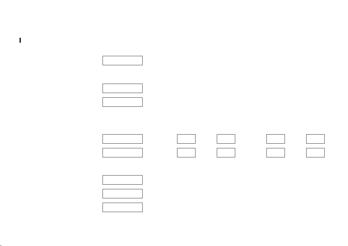
To unlock and open the tailgate:
Press button q on remote control,
operate button above
license plate
6 Tailgate - see page 26,
radio frequency remote control see page 23,
central locking system - see page 25,
anti-theft alarm system - see page 27.
Page 7
In brief 7
Back to overview
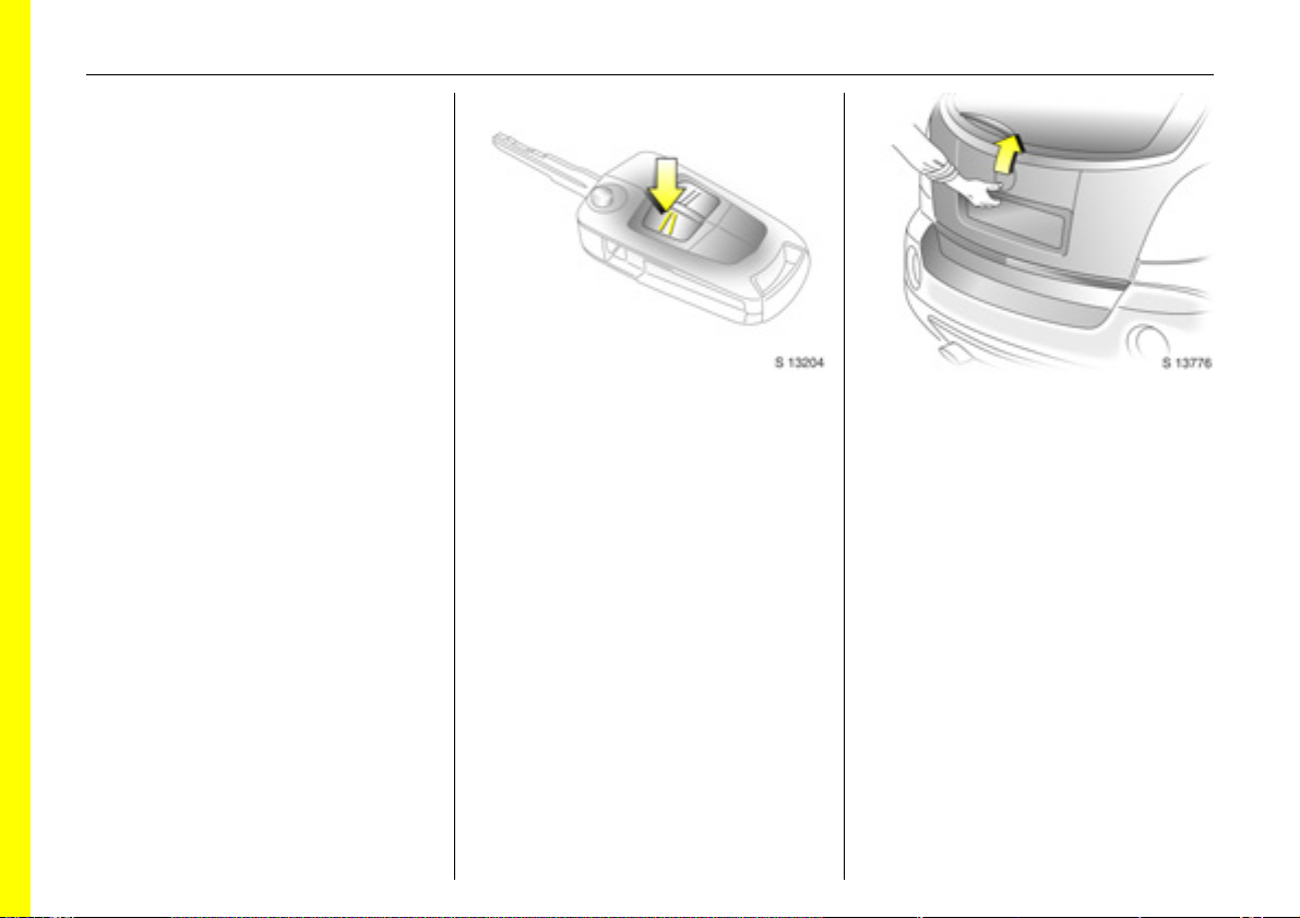
Front seat adjustment:
Pull handle, slide seat,
release handle
6 Seats - see page 36,
seat position - see page 38.
Adjusting front seat backrests:
Lift release lever on outboard side
of seat
Move seat backrest to suit seating position.
Do not lean on seat backrest whilst
adjusting it.
6 Seats - see page 36,
seat position - see page 38.
Adjusting the lumbar support 3:
Turn handwheel
Adjust lumbar support to suit personal
requirements.
Page 8
In brief8
Back to overview
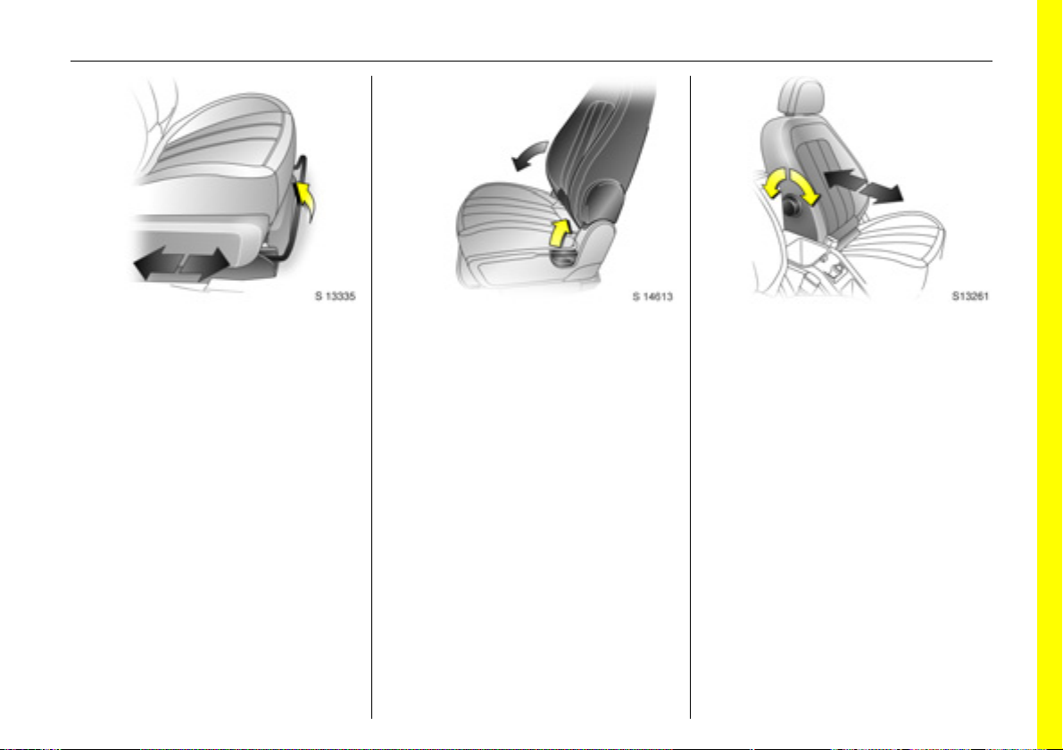
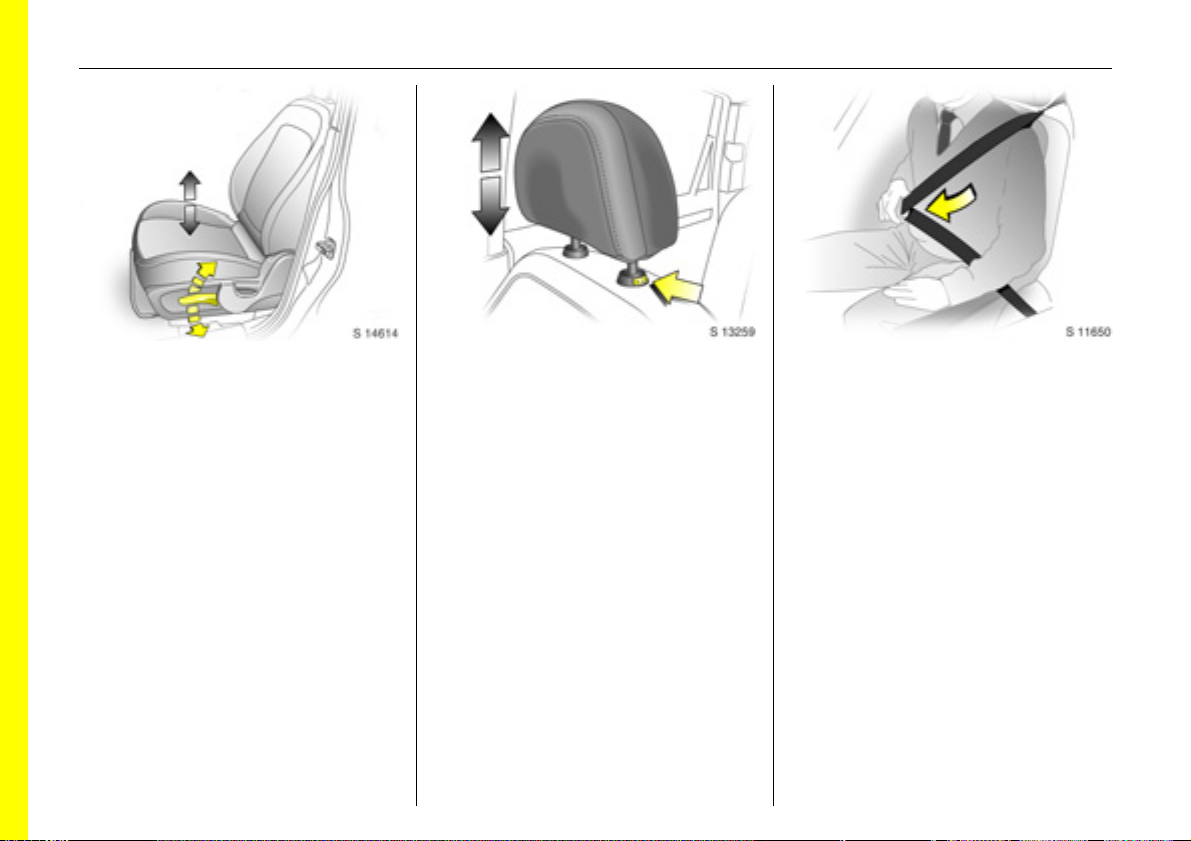
Adjusting seat height 3:
Raise or lower lever on outboard
side of seat
Lever pumping action
upward: raises seat
downward: lowers seat
6 Seats - see page 36,
seat position – see page 38.
Adjusting head restraint height:
Press release button,
adjust height, then release
6 Head restraints - see page 39,
head restraint position – see page 39.
Fitting seat belt:
Draw seat belt smoothly from
inertia reel, guide over shoulder
and engage in buckle
The belt must not be twisted at any point.
The lap belt must lie snugly against the
body.
The backrests must not be tilted back too
far (recommended maximum tilting angle
approx. 25°).
To release belt, press red button on belt
buckle.
6 Seat belts – see pages 43 to 47,
airbag systems – see page 52,
seat position – see page 38.
Page 9
In brief 9
Back to overview
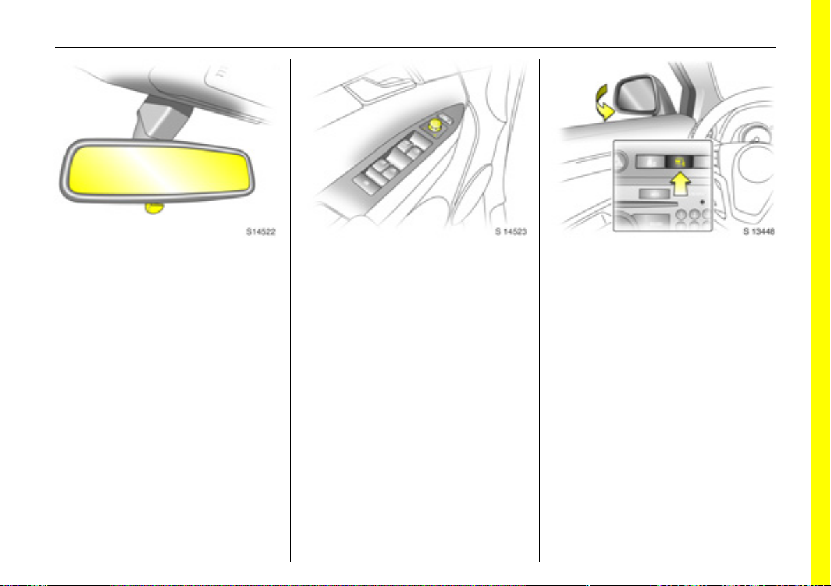
To adjust interior mirror:
Swivel mirror housing
Swivel lever on underside of mirror housing
to reduce dazzle at night.
Take care when driving with interior mirror
adjusted for night vision. Rear view may be
slightly distorted in this position.
6 Mirrors - see page 31,
automatic anti-dazzle interior mirror see page 32.
Electrically adjustable exterior
mirrors:
Four way switch in driver’s door
Move selector switch to L or R; four way
switch adjusts corresponding mirror.
6 Further information,
automatic anti-dazzle exterior mirrors see page 31,
heated exterior mirrors - see page 105.
Fold in exterior mirrors:
Manually: press lightly.
Electrically 3: with ignition switch in
positions ACC or ON, press button n and
both mirrors will fold in.
Press button n again; both mirrors will fold
to the driving position.
If a folded-in electric mirror has been
folded out manually, pressing button n
only folds the other mirror out. Pressing
button n again folds both mirrors back in.
Fold mirrors back into driving position
before driving the vehicle.
Page 10
10 In brief
Back to overview
Page 11

In brief 11
Back to overview
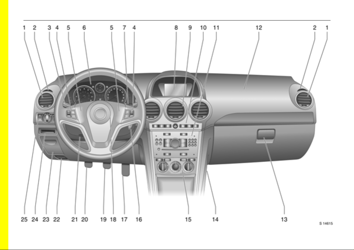
1 Side air vents................................... 104
Page
2 Door window defroster vents......... 104
3 Headlamp flash and main beam .... 14
turn signal lamps .............................. 14
Peripheral lighting............................. 98
cruise control 3 ...............................140
4 Infotainment system
remote control buttons................... 101
Trip computer 3..........................81, 88
5 Horn ................................................... 15
6 Instruments........................................ 70
7 Windscreen and tailgate
wipers and washers ....................15, 16
headlamp washers 3........................ 16
8 Central information display for time,
date, outside temperature,
Infotainment system,
check control 3 ................................. 91
Trip computer 3..........................81, 88
9 Centre air vents............................... 104
Page
10 Hazard warning................................ 14
Park pilot 3 ..................................... 142
Descent Control System (DCS)....... 138
Electronic Stability Control (ESC) ... 136
Front passenger’s
seat belt reminder 3......................... 46
Fold in exterior mirrors 3 ................. 30
Control indicator for
anti-theft alarm system 3 ................ 29
11 Infotainment system....................... 101
12 Front passenger’s airbag................. 52
13 Glove compartment.................. 64, 105
14 Fuse box .......................................... 182
15 Climate control................................ 103
16 Ignition switch ................................... 13
17 Accelerator pedal ........................... 127
Page
18 Driver’s airbag .................................. 52
19 Brake pedal............................. 127, 146
20 Clutch pedal 3 ........................ 127, 128
21 Steering wheel adjustment .............. 13
22 Bonnet release ................................ 171
23 Coin storage...................................... 67
24 Card holder ....................................... 67
25 Parking lamps ................................... 94
dipped beam .............................. 14, 95
automatic dipped beam
activation 3 ...................................... 95
headlamp range adjustment 3....... 97
front fog lamps ................................. 96
fog tail lamp ..................................... 96
instrument illumination .................... 98
Page 12

In brief12
Back to overview
Control indicators
ABS (Anti-lock Brake System):
u
see page 148.
Trailer indicator 3:
g
see page 70.
Brake system:
4
see pages 70, 145.
Park pilot 3:
r
see pages 71, 142.
DCS (Descent Control System):
5
see pages 71, 138.
AWD (All Wheel Drive):
B
see pages 71, 121.
ESC Active & Warning
7
(Electronic Stability Control):
see page 136.
ESC Not Ready:
A
see page 136.
ESC OFF:
J
see page 136.
Automatic headlamp range
q
adjustment 3:
see pages 71, 97.
Coolant temperature:
W
see pages 71, 195.
Electronic immobiliser:
o
see pages 22, 72.
Door open:
9
see page 72.
Engine electronics,
3
transmission electronics 3:
see pages 72, 134.
Airbag systems 3,
v
belt tensioners:
see pages 44, 52.
Tailgate open:
1
see page 72.
Driver’s seat belt reminder:
X
see page 72.
Turn signal lamps:
O
see pages 14, 72, 95.
Low fuel level:
Y
see pages 72, 76, 132, 225.
Front fog lamps:
>
see pages 73, 96.
Fog tail lamp:
r
see pages 73, 96.
Headlamp main beam:
P
see pages 14, 73, 95.
Low windscreen washer fluid:
G
see page 73.
Water in diesel fuel filter 3:
N
see pages 73, 194.
Change engine oil 3:
C
see page 73.
Preheating for diesel engines 3:
N
see pages 19, 73.
DPF (Diesel particle filter) 3:
I
see pages 73, 135.
Cruise control 3:
m
see page 140.
Engine oil level 3:
S
see page 73.
Power steering:
2
see page 73.
Anti-theft alarm system activation
a
without monitoring of passenger
compartment and vehicle tilt 3:
see page 28.
Engine oil pressure:
I
see page 74.
Alternator:
p
see page 74.
Exhaust emissions:
Z
see pages 74, 134.
Winter program:
0
see pages 74, 117.
Page 13
In brief 13
Back to overview
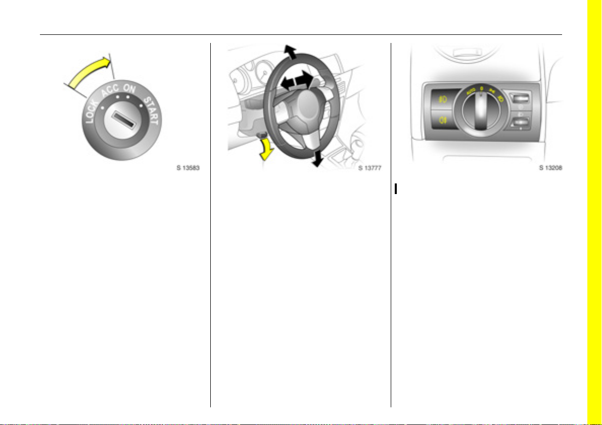
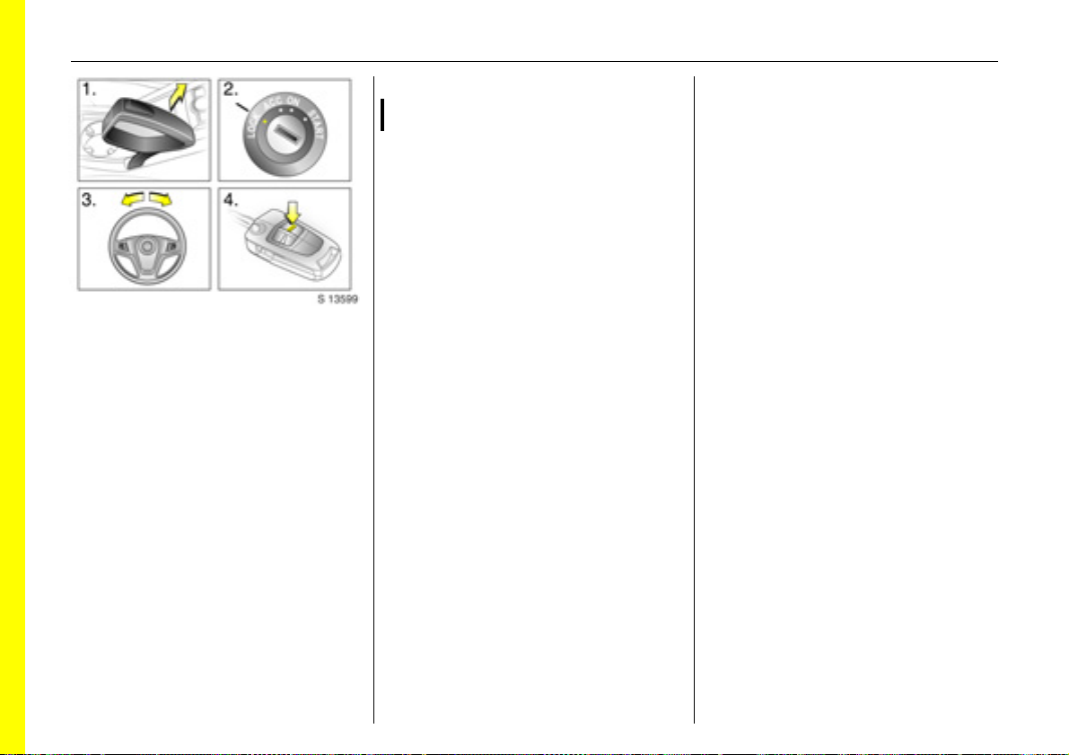
Steering column lock and ignition:
Turn key to position ACC.
To release lock,
rotate steering wheel slightly
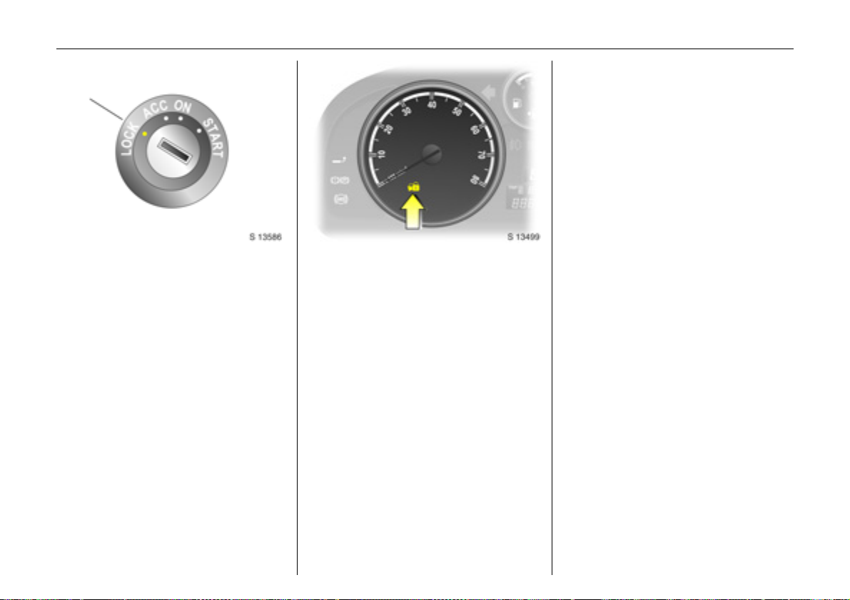
Positions:
LOCK = Ignition off
ACC = Steering unlocked, ignition off
ON = Ignition on, with diesel engine:
preheating
START = Start (transmission in neutral)
6 Starting - see page 19,
electronic immobiliser - see page 22,
parking the vehicle - see page 20.
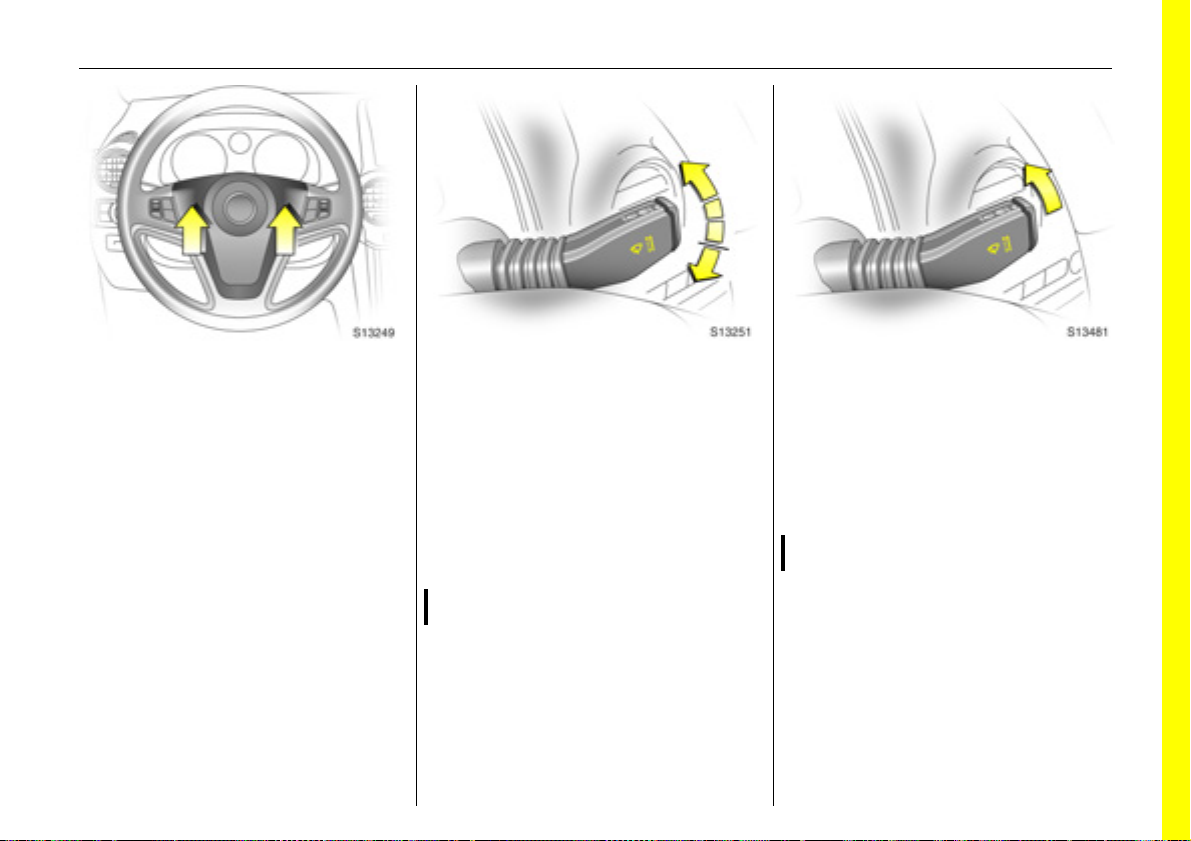
Steering wheel adjustment:
Move lever down,
adjust height and distance,
move lever up and engage
Adjust steering wheel only with vehicle
stationary and steering column lock
released.
Push the lever firmly upwards to ensure
that the steering wheel is locked in position.
6 Airbag systems - see page 52.
Exterior lamps
Turn light switch:
J =Off
8 =Parking lamps
9 = Dipped beam or
main beam
AUTO = Automatic dipped
beam activation
3
Press button:
> =Front fog lamps
r = Fog tail lamp
6 Headlamp warning device - see page 92,
further information - see page 94,
headlamp range adjustment 3 see page 97,
headlamps when driving abroad see page 100,
daytime running lamps 3 - see page 94.
Page 14
In brief14
Back to overview
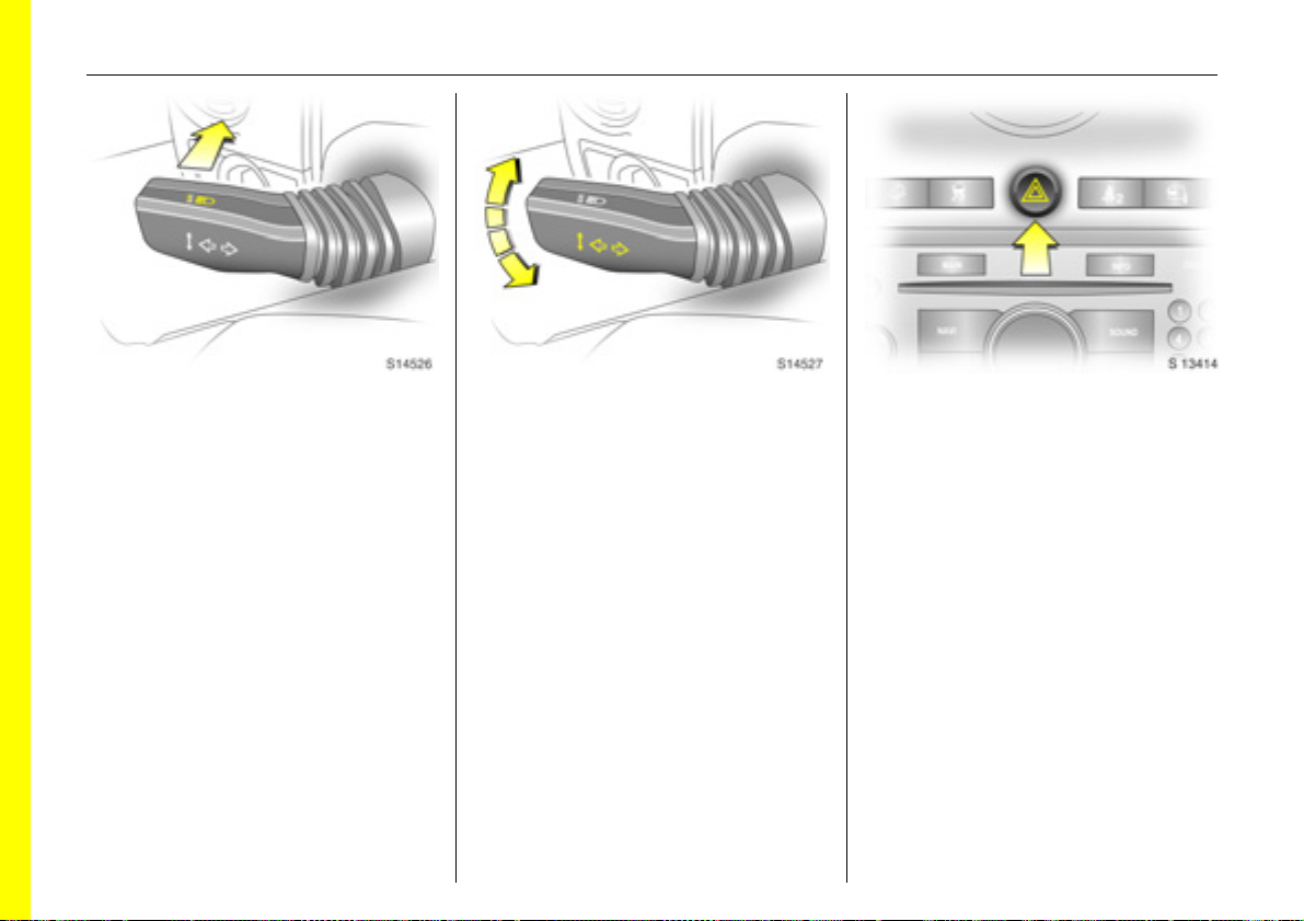
Headlamp flash, main and
dipped beam:
Headlamp
flash
= Pull lever
towards
steering wheel
Main beam = Push lever
forwards
Dipped beam = Pull lever back
towards
steering wheel
6 Main beam, headlamp flash see page 95.
Turn signal lamps:
Lever in rest position
Upwards = Right turn
Downwards = Left turn
6 Turn signal lamps - see page 95.
Hazard warning lamps:
On = Press ¨
Off = Press ¨ again
6 Hazard warning lamps - see page 97.
Page 15
In brief 15
Back to overview
Activate horn j:
Press either side of the
steering wheel
The horn will sound regardless of ignition
switch position.
6 Airbag systems - see page 52,
remote control on steering wheel see page 101.
Windscreen wipers:
Move lever upwards
J =Off
$ =Timed interval wipe
% =Slow
& =Fast
Press lever down from position J:
Single swipe.
6 Windscreen wipers - see page 92,
adjustable wiper interval - see page 92,
further information - see pages 198, 202,
205.
Automatic wiping with rain
sensor 3:
Move lever to automatic wiping
with rain sensor position $
The rain sensor detects the amount of
water on the windscreen and automatically
regulates the windscreen wipers.
6 Windscreen wipers - see page 92,
further information - see pages 198, 202,
205.
Page 16
In brief16
Back to overview
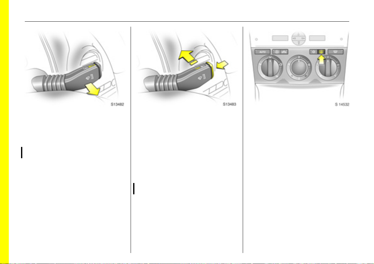
Operating windscreen and
headlamp washer systems 3:
Pull lever towards steering wheel
6 Windscreen and headlamp washer
systems - see page 93,
further information - see pages 199, 202,
205.
Tailgate wiper and washer
systems:
Wipers on = Push lever forward
Wipers off = Pull lever back
towards steering
wheel
Wash = Press and hold
button
6 Tailgate wiper and washer systems see page 93,
further information - see pages 198, 199,
202, 205.
Heated rear window,
heated exterior mirrors 3:
Press Ü =On
Press Ü again = Off
6 Air conditioning - see page 109,
heated rear window, heated exterior
mirrors - see page 105.
Page 17
In brief 17
Back to overview
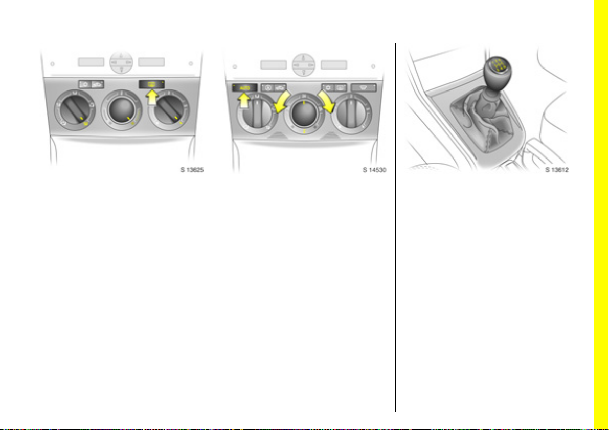
Drying misted up or iced up
windows:
Set air distribution to position l,
set the temperature rotary knob
to red and fan to position 4,
switch on heated rear window Ü
Close centre air vents, open side air vents
and direct them towards the door windows.
6 Heating, ventilation and air conditioning
system - see pages 106, 109.
To set automatic mode of
Electronic Climate Control 3:
Press AUTO button,
set temperature using
rotary knob
Open all air vents.
6 Electronic Climate Control (ECC) -
see page 111.
Manual transmission:
1 to 5 = 1st to 5th gear
R = Reverse gear
Only engage reverse gear when the vehicle
is stationary.
Page 18
In brief18
Back to overview
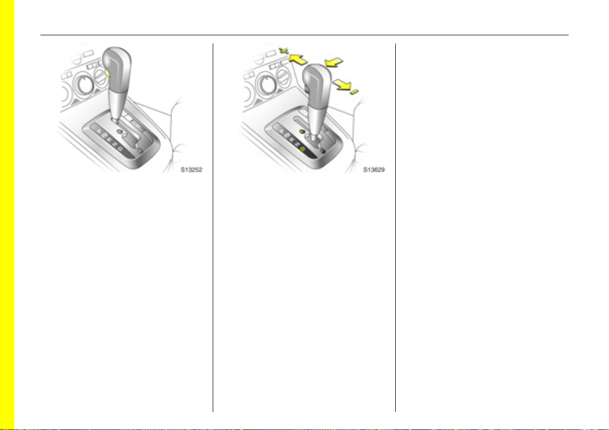
Automatic transmission 3:
P=Park position
R = Reverse
N = Neutral (idle)
D = Automatic gear selection
Starting is only possible in P or N. To move
from P or N, switch on ignition, depress foot
brake and press selector lever button.
Engage P or R: press selector lever button.
P: Only with vehicle stationary,
first apply hand brake
R: Only with vehicle stationary.
6 Automatic transmission - see page
115.
Manual mode:
<
= Shift to higher gear
]
=Shift to lower gear
6 Further information - see page 117.
Before starting-off, check:
z Tyre pressures and condition.
z Engine oil level and fluid levels in engine
compartment (see page 192).
z All windows, mirrors, exterior lighting
and license plates are free from dirt,
snow and ice and are operational.
z Objects are securely located and will not
be thrown forward in the event of
sudden braking.
z Seats, seat belts and mirrors are
correctly adjusted.
z All gauges and control indicators.
z Brake operation.
Page 19

Starting the engine:
Back to overview
Manual transmission in neutral,
Depress clutch and foot brake,
Automatic transmission in P or N,
Do not accelerate
Petrol engines:
TurnkeytoSTARTand release it
Diesel engines:
Turn key to ON, when preheating
control indicator N
extinguishes
1)
, turn key to START
and release it
Key returns automatically to ON position
when released.
Start attempts should not last longer than
15 seconds. If engine does not start, wait
10 seconds before repeating starting
procedure.
The increased engine speed automatically
returns to normal idling speed as the
engine temperature rises.
Drive at a moderate speed, especially in
cold weather, until normal engine
operating temperatures have been
reached.
6 Electronic immobiliser - see page 22,
diesel fuel system - see page 171,
further information - see pages 127, 129,
131.
In brief 19
Releasing the hand brake:
Raise lever slightly,
press release button,
lower lever fully
To reduce operating forces, depress foot
brake at the same time.
Do not drive with hand brake on, to avoid
damage to brakes on the rear wheels. Do
not apply hand brake while vehicle is in
motion or as a substitute for the foot brake.
Drive carefully, economically and with the
environment in mind. While driving, do not
do anything that could distract you.
6 Hand brake - see page 147.
1)
Preheating system switches on only if outside
temperature is low.
Page 20
In brief20
Back to overview
Parking the vehicle:
Apply hand brake firmly,
close windows,
switch off engine, remove key,
engage steering column lock,
lock vehicle
6 Further information - see pages 22, 128,
radio frequency remote control see page 23,
central locking system - see page 25,
anti-theft alarm system - see page 27.
Advice when parking:
z Always apply hand brake firmly and as
firmly as possible on slopes.
z Push key into ignition switch before
removing (vehicles with automatic
transmission 3: depress foot brake and
shift into P before removing key). Turn
steering wheel until lock is felt to engage
(anti-theft protection).
z If the vehicle is parked on a level surface
or a hill, select 1st gear before switching
ignition off (vehicles with automatic
transmission 3: move selector lever to P).
Also turn front wheels away from kerb if
parked on an uphill slope.
If the vehicle is parked on a downhill
slope, select reverse gear before
switching ignition off (vehicles with
automatic transmission 3: move selector
lever to P). Also turn front wheels
towards kerb.
z Switch off exterior lamps, otherwise the
headlamp warning device will sound
when the driver’s door is opened.
z Cooling fans may run on after the engine
has been switched off.
z Do not park on easily ignitable surfaces
as hot exhaust system temperatures
could cause the surface to ignite.
That was the most important
information for your first drive in
your Antara in brief.
Your vehicle has still more
instruments and controls,
possibly also optional equipment.
The remaining chapters of the
Owner’s Manual contain
important information on
operation, safety and
maintenance as well as a
complete index.
Page 21
Locks, doors, windows 21
Back to overview
Locks, doors, windows
Replacement keys .............................. 21
Car Pass............................................... 21
Key with foldaway key section 3 ...... 21
Electronic immobiliser......................... 22
Radio frequency remote control ....... 23
Central locking system ....................... 25
Tailgate ............................................... 26
Mechanical anti-theft locking
system 3 ........................................... 27
Anti-theft alarm system 3 ................. 27
Child safety locks................................ 30
Exterior mirrors.................................... 30
Interior mirror ...................................... 31
Electric windows.................................. 32
Sun visors............................................. 34
Slide/tilt sun roof 3 ............................. 34
Replacement keys
The key is a constituent of the electronic
immobiliser. In case of loss, replacement
keys can be ordered from your Opel
Partner by quoting the key number and
Vehicle Identification Number (VIN).
Once a new transmitter is coded, the lost
transmitter will not unlock your vehicle.
Ordering keys from an Opel Partner
guarantees problem-free operation of the
electronic immobiliser.
Keep spare key in a safe place.
Locks - see page 205.
Car Pass
The Car Pass contains all of the vehicle’s
data and should therefore not be kept in
the vehicle.
Have your Car Pass on hand when
consulting an Opel Partner.
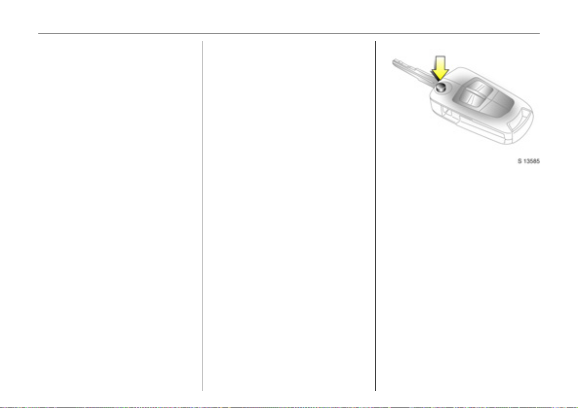
Key with foldaway key section 3
Press button to extend. Press button to
retract; key section audibly engages.
Page 22
Locks, doors, windows22
Back to overview
Note
The immobiliser does not lock the doors.
Therefore, after leaving the vehicle, always
lock it and switch on the anti-theft alarm
system 3 - see pages 25, 27.
Electronic immobiliser
The system checks whether the vehicle may
be started using the key that has been
inserted. If the key is recognised as
"authorised", the vehicle can be started.
The check is carried out via a transponder
housed in the key.
The electronic immobiliser is automatically
activated when the key is turned to LOCK
position and removed from the ignition
switch.
Control indicator
The control indicator illuminates when the
ignition is switched on, then extinguishes.
If the control indicator stays illuminated
after the ignition is switched on, there is a
fault in the immobiliser system.
z Turn key to LOCK position and remove,
z wait approximately two seconds,
z then repeat starting procedure.
If the control indicator fails to extinguish,
try to start the engine using the spare key
and seek the assistance of a workshop.
o for immobiliser
Page 23
Locks, doors, windows 23
Back to overview
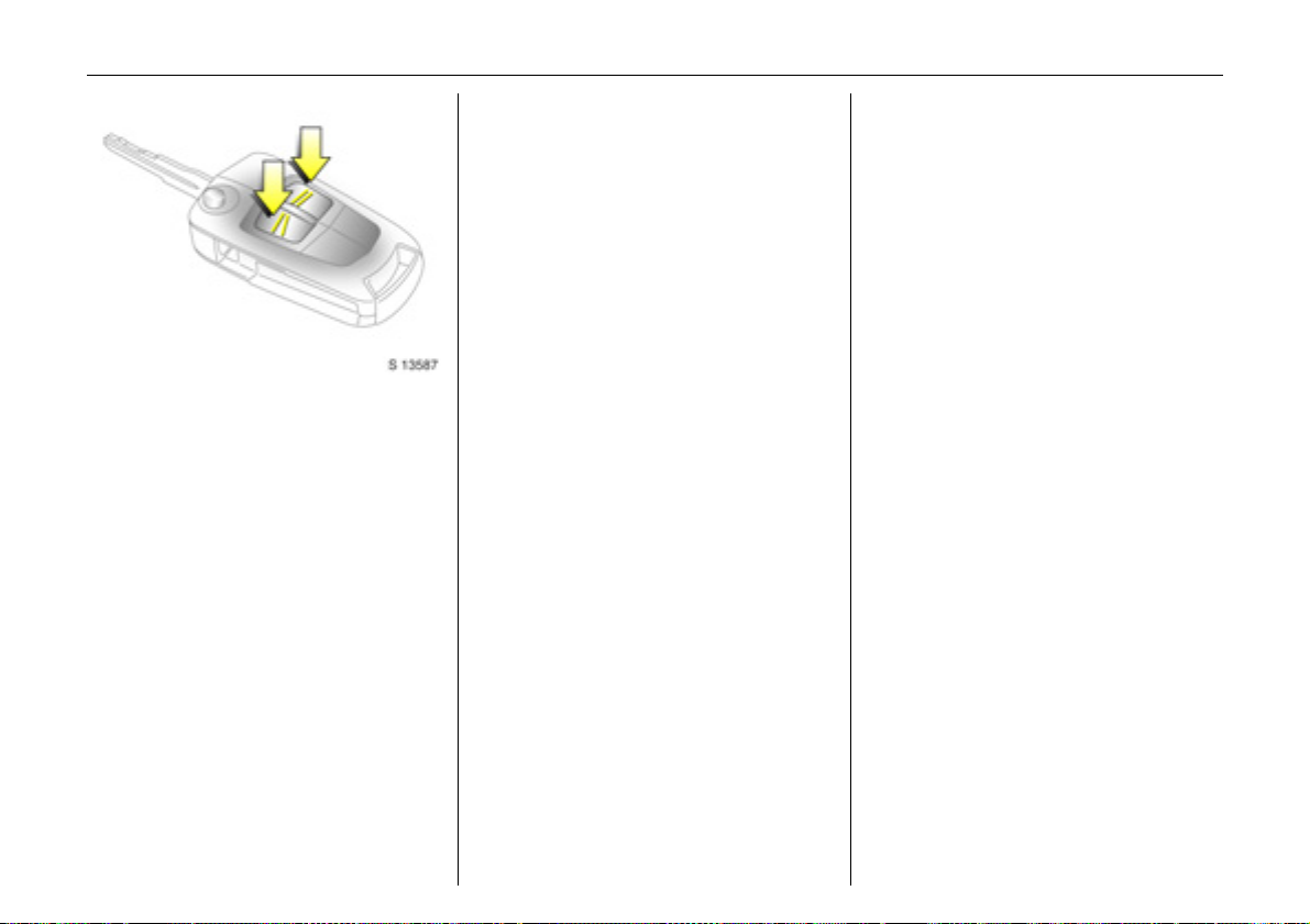
Radio frequency remote control
The remote control is used to operate:
z Central locking system,
z Mechanical anti-theft locking system 3,
z Anti-theft alarm system 3.
The remote control has a range of approx.
6 metres. The range may be reduced due
to environmental conditions or shadowing
and reflection of the radio waves.
To operate the remote control, direct the
remote control unit at the vehicle.
Treat the remote control unit with care:
it should be protected against moisture,
kept out of direct sunlight and should not
be operated unnecessarily.
Do not place heavy objects on the remote
control unit, and avoid dropping it.
The hazard warning lamps come on to
indicate that the remote control is
operational.
Central locking system
see page 25.
Mechanical anti-theft locking system 3
see page 27.
Anti-theft alarm system 3
see page 27.
Page 24
Locks, doors, windows24
Back to overview
Fault
If the central locking system cannot be
operated with the remote control, this may
be due to the following reasons:
z The remote control is out of range.
z The battery voltage of the remote
control is too low. Change the battery in
the remote control unit.
z The remote control has been repeatedly
operated outside the vehicle’s reception
range (e.g. at too great a distance from
the vehicle). The remote control must be
reprogrammed. We recommend you
consult your Opel Partner.
z The system has been overloaded as a
result of repeated operation at short
intervals. The power supply is cut-off for
a brief period.
z Interference from higher power radio
waves from other sources.
Lock or unlock the doors manually using
the key or central locking switch see page 25.
Have cause of fault remedied by a
workshop.
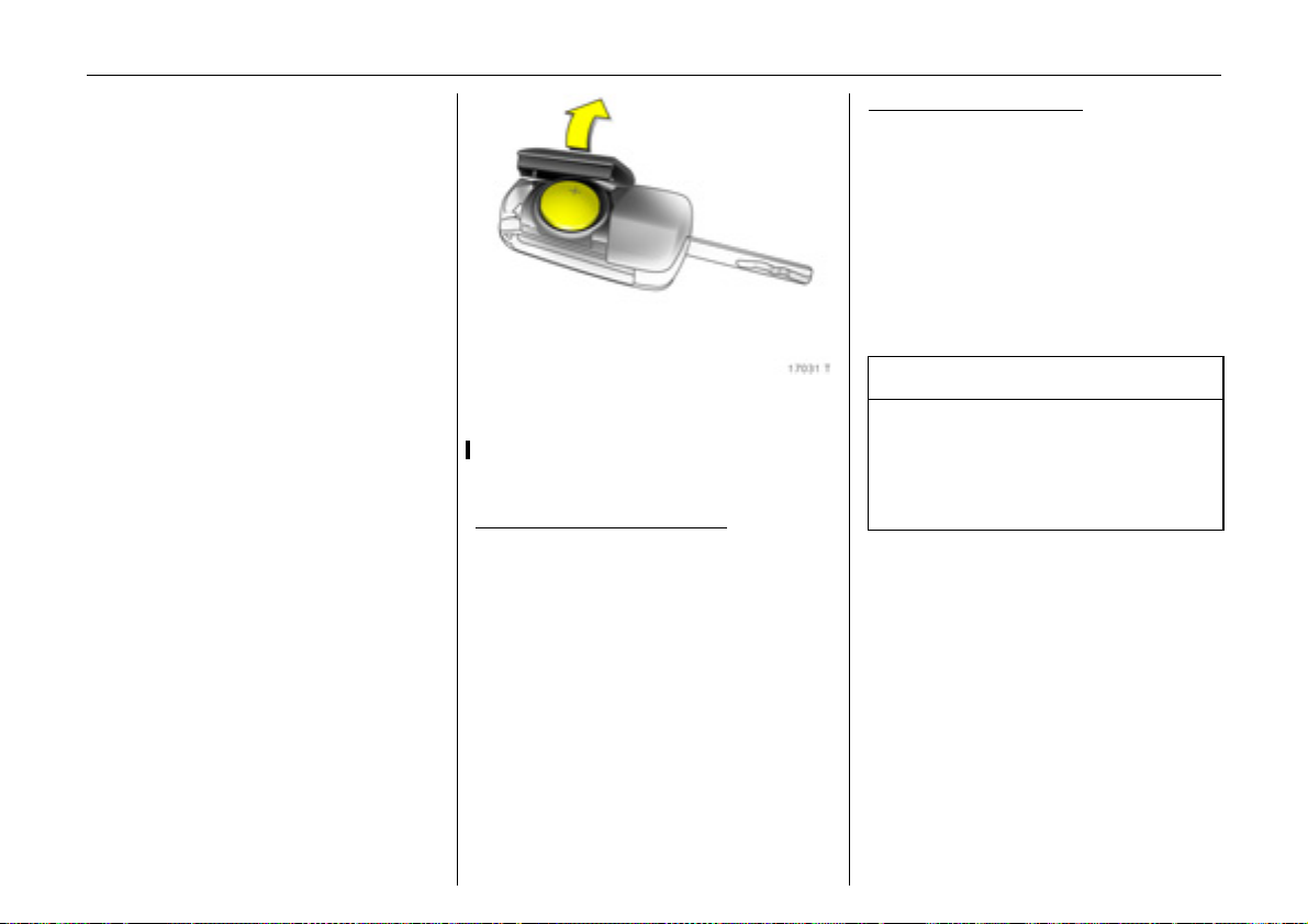
Changing battery in remote control unit
Replace the battery in accordance with the
information on pages 206 to 212 or when
the range of the remote control starts to
become reduced.
Key with foldaway key section
open cover by hand.
Remove used battery, taking care to avoid
touching the circuit board to other
components.
Ensure the new battery is installed correctly
with positive (+) side facing up.
Close cover, ensuring it audibly engages in
the key part.
:
Key with fixed key section
insert a small screwdriver in the notch on
the cover and prise it open.
Remove used battery, taking care to avoid
touching the circuit board to other
components.
Ensure the new battery is installed correctly
with positive (+) side facing down towards
the base.
Close cover, ensuring it audibly engages in
the key part.
:
9 Warning
Used lithium batteries can harm the
environment. Make sure that you dispose
of old batteries in accordance with
environmental protection regulations.
Do not dispose with household refuse.
Page 25
Central locking system
Back to overview
For front doors, rear doors, tailgate and
tank flap.
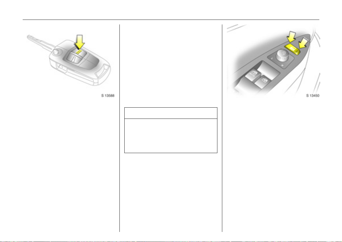
To lock:
Press button p on remote control
- or With the doors closed, press central locking
m in driver’s door.
switch
The central locking system can be
activated with the windows open.
Always ensure that the doors, bonnet,
tailgate, sun roof 3 and windows are
properly closed and that there are no
passengers left in the vehicle before
locking with the remote control.
To unlock:
Press button q on remote control
- or Press central locking switch
door.
If no door is opened within approx.
30 seconds after the vehicle has been
unlocked via the remote control, the vehicle
is relocked automatically and anti-theft
alarm 3 is reactivated.
When button q is pressed, the instrument
panel illuminates for approx. 30 seconds or
until ignition switch is turned to the
ACC position.
m in driver’s
9 Warning
For safety reasons, the vehicle cannot be
locked or unlocked via the remote control
(and the anti-theft system 3 will not be
activated) if the key is in the ignition
switch.
Locks, doors, windows 25
Central locking switch
Use the central locking switch to lock or
unlock the doors, tailgate and tank flap
from inside the vehicle.
Press the right part of the switch to lock or
the left part of the switch to unlock.
m
Page 26
Locks, doors, windows26
Back to overview
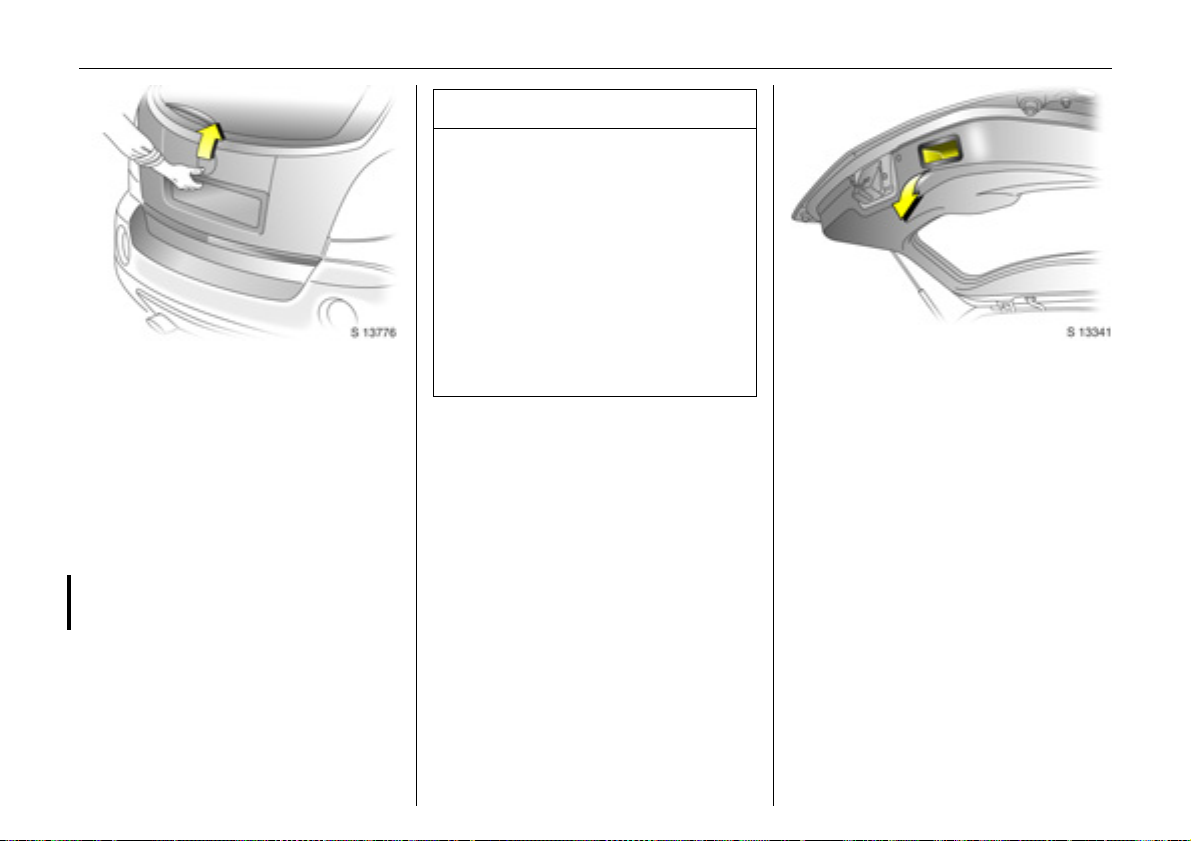
Tailgate
To unlock and open
Press button q on remote control
- or Press central locking switch
door.
The tailgate is unlocked together with the
doors and can be opened by operating the
button above the license plate and lifting
the tailgate.
With the engine running, the tailgate will
only unlock when the hand brake is applied
or automatic transmission 3 is in P.
If the tailgate is open when the ignition is
switched on, tailgate open control
indicator 1 illuminates in the instrument
panel.
m in driver’s
9 Warning
Ensure there are no obstructions and that
there is adequate clearance when
opening the tailgate.
Do not drive with tailgate open or ajar,
e.g. when transporting bulky objects,
since toxic exhaust gases could
penetrate the vehicle interior.
If driving with tailgate open is necessary,
set fan to highest speed, open all air
vents, close windows and ensure air
recirculation mode is off, to allow entry of
outside air.
To close and lock
There is a handle on the inside of the
tailgate for closing the luggage
compartment.
Close tailgate by pushing it down so it
latches securely. Ensure tailgate is fully
closed before driving.
To lock tailgate, together with the doors:
Press button p on remote control
- or Press central locking switch
door.
If the ignition is switched on, the tailgate
open control indicator 1 extinguishes in
the instrument panel.
m in driver’s
Page 27
Locks, doors, windows 27
Back to overview
Mechanical anti-theft locking
system 3
9 Warning
Do not use the system if there are people
in the vehicle. The doors cannot be
unlocked from inside.
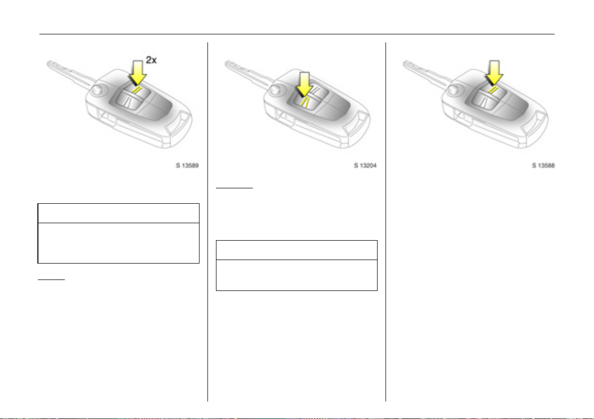
To lock:
All doors and the tailgate must be closed;
press button p on remote control again
within 3 seconds after locking
- or Turn key in driver's door lock towards rear
of vehicle again within 3 seconds after
locking, then turn it back to the vertical
position and remove.
Lock buttons on all doors are positioned
such that doors cannot be opened.
To unlock
Press button q on remote control
- or Turn key in driver's door lock towards front
of vehicle, then turn it back to the vertical
position and remove.
:
9 Warning
Unlocking is not possible in any other
way, so keep spare key in a safe place.
Anti-theft alarm system 3
The system monitors:
z Front and rear doors.
z Tailgate, bonnet.
z Ignition switch.
z Passenger compartment 3.
z Vehicle tilt, e.g. if it is raised 3.
z Siren power supply 3.
Page 28
Locks, doors, windows28
Back to overview
9 Warning
Do not use the system if there are
passengers in the vehicle. The doors
cannot be unlocked from the inside when
the alarm is activated.
The remote control unit is used to operate
the anti-theft alarm system.
To activate
Always ensure that the doors, bonnet,
tailgate, sun roof 3 and windows are
properly closed and that there are no
passengers left in the vehicle before
activating anti-theft alarm system.
Press button p on remote control
- or Lock driver’s door by turning key in door
lock towards rear of vehicle then turn it
back to the vertical position and remove;
z Hazard warning lamps flash once,
z All doors are locked,
z Anti-theft system is activated after
approx. 30 seconds.
Confirm that the control indicator starts
flashing slowly, after illuminating for
approx. 30 seconds, to show that the antitheft system has been activated.
If button p is pressed again, the anti-theft
alarm system will activate automatically,
bypassing the 30 second delay.
If the hazard warning lamps do not flash
on activation or the control indicator
flashes quickly, this may indicate that a
door, the tailgate or the bonnet is not fully
closed.
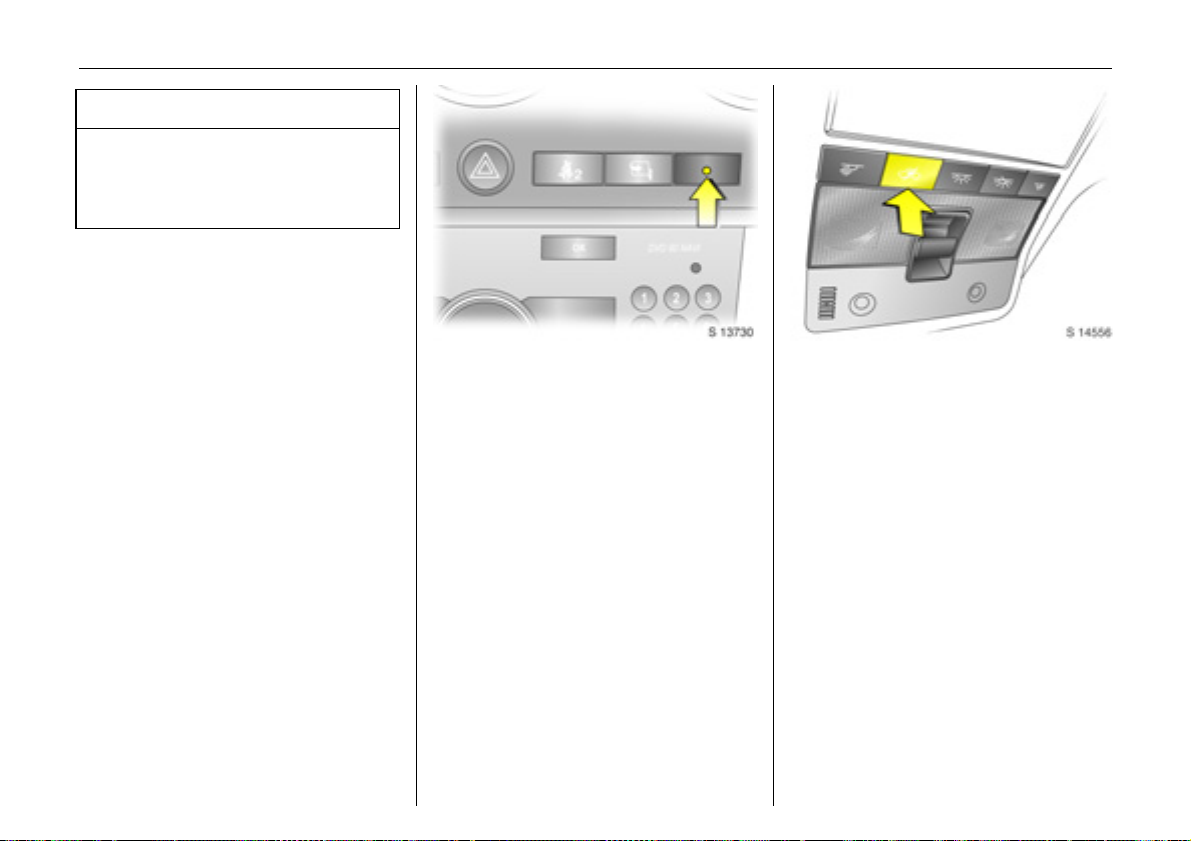
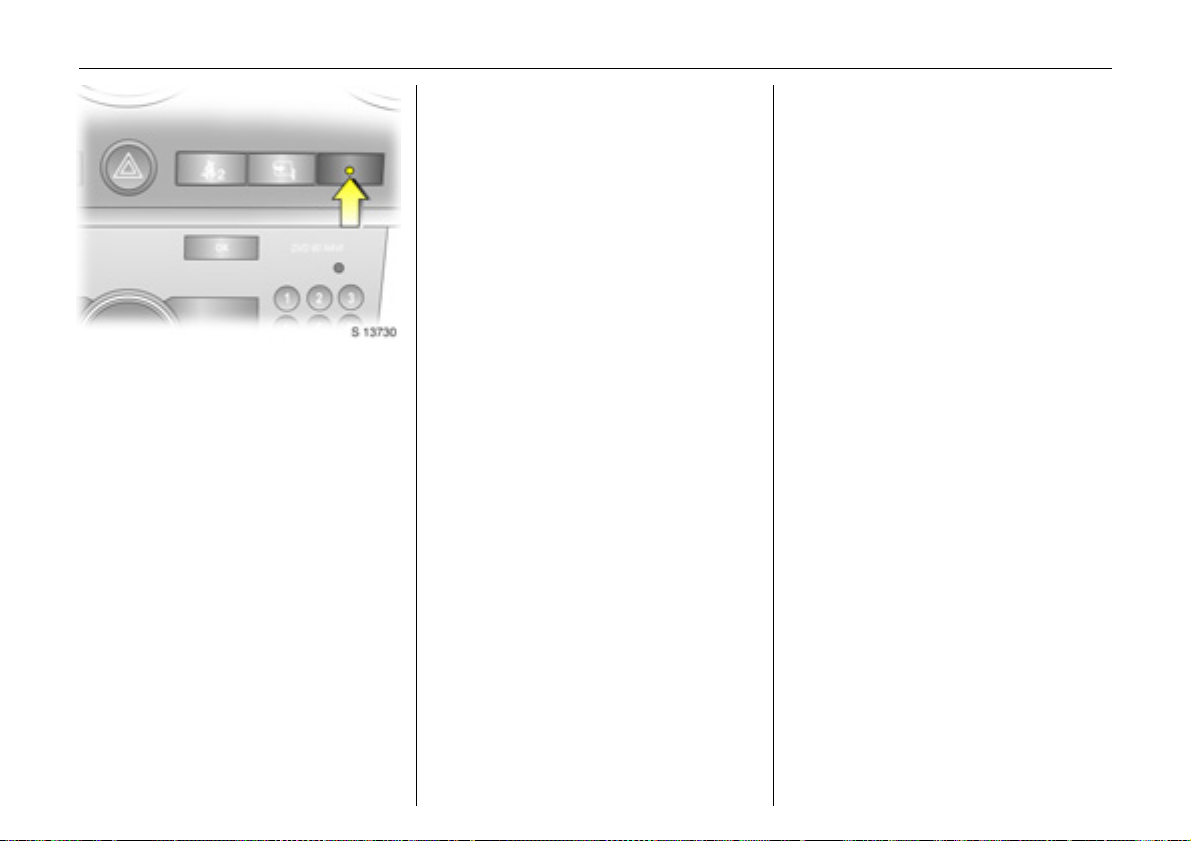
Activation without monitoring of
passenger compartment and vehicle tilt 3
Switch on when, for example, animals are
to be left in the vehicle.
1. Close tailgate and bonnet.
2. Press button
Control indicator
yellow in the instrument panel.
3. Close doors.
4. Switch on anti-theft alarm system.
Control indicator for anti-theft alarm
system illuminates. After a 30 second
delay, the system is activated without
monitoring of the passenger
compartment or vehicle tilt.
Control indicator
illuminated in the instrument panel
until the system is switched off by
pressing button
a in the roof lining.
a illuminates in
a remains
a again.
Page 29
Locks, doors, windows 29
Back to overview
Control indicator for anti-theft alarm
system 3
The control indicator illuminates to show
that the system is operational when the
doors are locked with the remote control or
the key. When the doors are unlocked with
the key or remote control, the control
indicator extinguishes.
To deactivate
Press button q on remote control
- or Unlock driver’s door by turning key in door
lock towards front of vehicle, then turn it
back to the vertical position and remove:
z Hazard warning lamps flash twice,
z All doors are unlocked,
z Anti-theft system is deactivated.
If the driver’s door is not opened, or the
engine is not started within 30 seconds of
deactivation, all doors are automatically
relocked and the system is reactivated.
If the alarm has been triggered, the hazard
warning lamps will not flash upon
deactivation.
Note
The anti-theft alarm system cannot be
deactivated in any other way, so keep a
spare key in a safe place.
Changes to the vehicle interior, such as the
use of seat covers, could impair the
function of passenger compartment
monitoring 3.
Alarm
While the alarm system is switched on, the
alarm can be triggered, indicated by:
z an acoustic signal (horn) and
z a visual signal (exterior lamps).
The number and duration of the alarms are
legally established.
The alarm is stopped by pressing q or p
on the remote control or by unlocking
the driver’s door with the correct key.
The anti-theft alarm system is deactivated
at the same time.
Page 30
Locks, doors, windows30
Back to overview
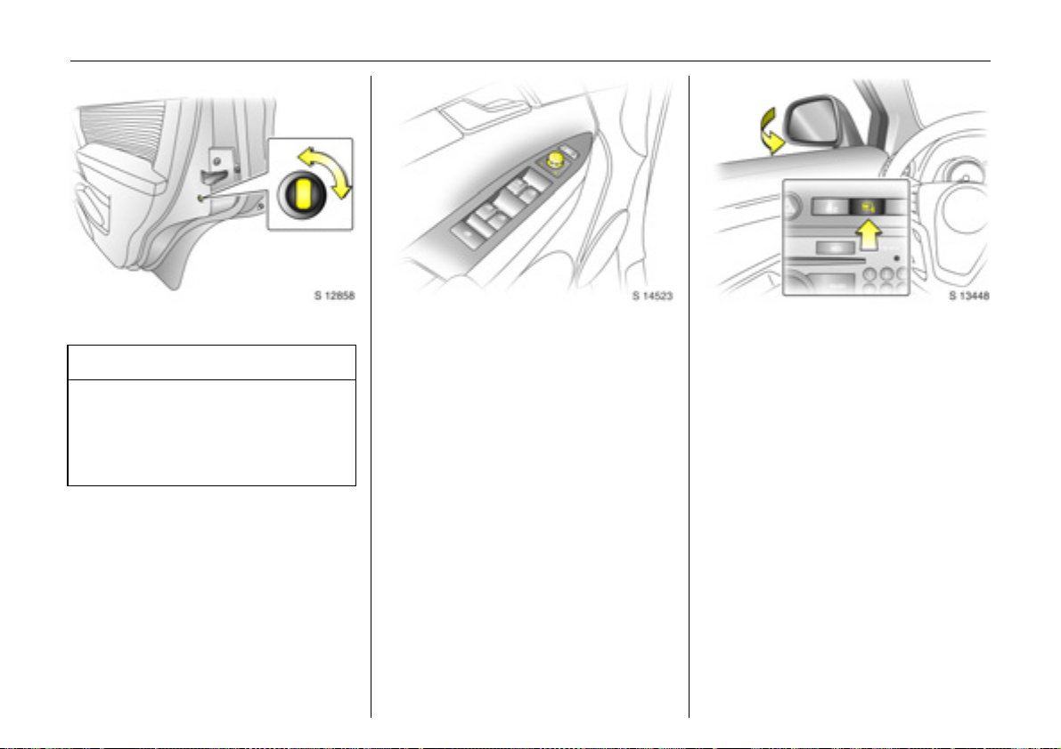
Child safety locks
9 Warning
Use the child safety locks whenever
children are occupying the rear seats.
Disregard may lead to injuries or
endanger life. Vehicle passengers must
be informed accordingly.
To engage lock, open door, insert key into
child safety lock and turn lock from the
vertical to the horizontal position. Door
cannot then be opened from inside.
To unlock door while child safety lock is
activated, pull up lock button and open
door from outside. Do not pull inside door
handle while child safety lock is activated.
Exterior mirrors
Electrically adjustable exterior mirrors
Adjust with the four way switch in driver’s
door: move selector switch to L or R;
four way switch adjusts corresponding
mirror.
The mirror glass swivels in the same
direction as the activation of the four way
switch.
Heated exterior mirrors 3 - see page 105.
Fold in exterior mirrors
Manually: the exterior mirrors can be
folded in by pressing lightly on the outside
of the mirror housing.
Electrically 3: with ignition switch in
positions ACC or ON, press button n and
both mirrors will fold in.
Press button n again; both mirrors will fold
to the driving position.
If a folded-in electric mirror has been
folded out manually, pressing button n
only folds the other mirror out. Pressing
button n again folds both mirrors back in.
Fold mirrors back into driving position
before driving the vehicle.
Page 31

Locks, doors, windows 31
Back to overview
For the safety of pedestrians, the exterior
mirrors will swing out of their normal
mounting position in the event of an
accident-like impact.
As exterior mirrors are convex, objects are
closer than they appear. Use interior mirror
to judge size and distance of objects.
Do not scrape ice from exterior mirrors or
force them if frozen. Use a de-icer.
Automatic anti-dazzle exterior mirrors 3
Dazzle is automatically reduced.
Exterior mirrors dim to reduce glare
automatically in conjunction with the
automatic anti-dazzle interior mirror 3 see page 32, Fig. S13260.
Interior mirror
To adjust interior mirror, swivel mirror
housing.
Swivel lever on underside of mirror housing
to reduce dazzle at night.
Take care when driving with interior mirror
adjusted for night vision. Rear view may be
slightly distorted in this position.
Page 32

Locks, doors, windows32
Back to overview
Automatic anti-dazzle interior mirror 3
Dazzle is automatically reduced.
With the ignition off, the mirror does not
dim.
Press button on mirror housing to turn
function on. Button will illuminate.
Press button again to turn off.
There are two light sensors in the mirror
housing. To avoid interference and loss of
function, do not cover the sensors or hang
anything on the mirror.
Electric windows
9 Warning
Care must be taken when operating the
electrically operated door windows.
There is a risk of injury, particularly for
children, and a danger that articles could
become trapped. Vehicle passengers
must be informed accordingly.
If there are children on the rear seats,
press the switch in the driver’s door to
lock rear window operation. Rear
windows can then only be operated via
the driver’s door switches.
Keep a close watch on the windows when
closing them. Ensure that nothing
becomes trapped in them as they move.
Before leaving the vehicle, remove the
ignition key in order to prevent
unauthorized operation.
Operational with key in ignition switch
positions ACC or ON. If key is in LOCK
position or removed, windows can be
operated for 10 minutes or until driver’s
door is opened.
Operated via four switches located in the
driver’s door.
For incremental operation, briefly pull or
press the switch.
For automatic 3 opening or closing, pull or
press the switch longer. Pull or press the
switch again to stop the movement.
Page 33

Safety function 3
Back to overview
If the window glass encounters resistance
above the middle of the window during
automatic closing, it will stop immediately
and will be opened again.
In the event of difficulty due to frost or the
like, press the relevant window switch
several times until the window is closed.
Locks, doors, windows 33
Additional switches are located in the front
passenger’s door and the rear doors.
The rear windows do not open fully.
Child safety system for rear windows
Press z switch in driver’s door to lock rear
window operation.
With the lock on, rear passenger windows
can only be operated via the switches in
the driver’s door.
Page 34

Locks, doors, windows34
Back to overview
Sun visors
Use the sun visor to protect from glare by
pulling it up, down or swivelling it to the
side.
Sun visors have vanity mirrors and a ticket
holder 3 on the rear.
When the vanity mirror covers are opened,
the sun visor lamp 3 will illuminate.
Slide/tilt sun roof 3
Operated via switch in roof lining when the
ignition switch is in positions ACC or ON.
With key in LOCK position in the ignition
switch or removed, the slide/tilt sun roof
can be adjusted for up to 10 minutes or
until a door is opened.
For incremental operation, briefly press the
button. For automatic opening or closing,
press and hold the switch.
To open
Press switch rearwards; it will open
automatically unless the switch is pressed
again in another direction, or released.
To close
Press and hold switch forwards. Release
switch when sun roof reaches desired
position.
To tilt
Press and hold switch upwards. Release
switch when sun roof reaches desired
position.
To return sun roof to its original position,
press and hold switch downwards. Release
switch when sun roof reaches desired
position.
Page 35

Note
Back to overview
z If the top of the sun roof is wet, tilt it to
allow water to run off before opening the
sun roof.
z When carrying a roof load, check the
clearance of the sun roof, to avoid
damage.
9 Warning
Care must be taken when operating the
sun roof. Do not place any objects or
body parts in the sun roof opening.
Keep sun roof clear of debris. Do not
place heavy objects on or around
sun roof.
When leaving the vehicle unattended,
ensure the sun roof is fully closed.
Locks, doors, windows 35
Page 36

Seats, interior36
Back to overview
Seats, interior
Front seats .......................................... 36
Rear seats............................................ 41
Seat belts............................................. 42
Child restraint systems 3 ................... 47
Airbag systems ................................... 52
Storage ................................................ 59
Drink holders ....................................... 67
Ashtrays 3........................................... 67
Warning triangle ¨ 3,
First aid kit +3................................ 68
Power outlets ...................................... 68
Assist grips .......................................... 69
Front seats
9 Warning
Never adjust seats whilst driving as they
could move uncontrollably.
Adjust seat longitudinally
To adjust, pull the handle on the front seat,
slide the seat and release the handle.
Adjusting front seat backrests
To adjust, lift the release lever, move seat
backrest to suit seating position and lock in
position when the lever is released.
Do not lean on the seat backrest whilst
adjusting it.
Page 37

Seats, interior 37
Back to overview
Electrically adjustable front seat 3
9 Warning
Care must be taken when operating
electrically adjustable seats. There is a
risk of injury, particularly for children and
a danger that articles could become
trapped.
Keep a close watch on the seats when
adjusting them.
Vehicle passengers must be informed
accordingly.
Adjusting the lumbar support 3
To adjust, turn the handwheel whilst
relieving the load on the backrest.
Adjust lumbar support to suit personal
requirements.
Adjusting seat height 3
To adjust, operate lever on side of seat.
Lever pumping action
upward: raises seat
downward: lowers seat
Page 38

Seats, interior38
Back to overview
Seat position
Adjust driver’s seat such that, with the
driver sitting upright, the steering wheel is
held in the area of its upper spokes with the
driver’s arms slightly bent.
Slide front passenger’s seat as far back as
it will go.
The seat backrests must not be tilted back
too far (recommended maximum tilting
angle approx. 25°).
9 Warning
Adjustment
The seat position can be adjusted by
means of switches on the outboard side of
the seat.
Adjusting the longitudinal position:
Move front switch forwards/backwards.
Height adjustment:
To adjust height of front part of seat
cushion, push front part of switch up/down.
To adjust height of rear part of seat
cushion, push rear part of switch up/down.
To adjust height of entire seat cushion,
push both front and rear parts of switch
up/down.
Seat backrest adjustment:
Move upper part of rear switch forwards/
backwards.
Operate switch until desired seat position is
reached. Seat position - see next column.
After adjusting the seat, adjust height of
seat belt - see page 47.
The seat backrest must not be tilted back
too far (recommended maximum tilting
angle approx. 25°).
Disregard can lead to injuries which could
be fatal. Vehicle passengers must be
informed accordingly.
Page 39

Head restraints
Back to overview
To adjust head restraint height, press
release button, adjust height to suit then
release the button.
Pull head restraint up to raise. Push head
restraint down while pressing the release
button to lower the head restraint.
e head restraints 3
Activ
In the event of a rear-end impact, the
active head restraints automatically tilt
forwards. The head is more effectively
supported by the head restraint and the
danger of hyperextension in the area of the
cervical vertebra is reduced.
Do not attach objects or components that
are not approved for your vehicle to the
head restraints. These affect the protective
effect of the head restraints and can be
propelled through the vehicle in an
uncontrolled manner if the driver brakes
hard or an accident occurs.
Seats, interior 39
Head restraint position
For maximum protection, the middle of the
head restraint should be at eye level. If this
is not possible for extremely tall persons,
set to highest position, and set to lowest
position for extremely small persons.
9 Warning
Disregard can lead to injuries which could
be fatal. Vehicle passengers must be
informed accordingly before moving
away.
Page 40

Seats, interior40
Back to overview
Removing the head restraints
Insert a suitable tool into the small hole in
the side of the guide sleeve without the
release button and depress the lock. Press
the release button on the other guide
sleeve and pull up the head restraint.
Stow head restraints securely in luggage
compartment.
Front seat armrest 3
The armrest can be slid forwards. Pull up
and hold upper lever and slide the armrest
forwards.
To return armrest to its rearmost position,
slide it back until it latches into position.
Console box in front armrest - see page 65.
Folding down the passenger’s seat 3
Push front passenger’s seat head restraint
all the way down - see page 39.
Slide front passenger’s seat as far back as
it will go.
Fold seat forwards by lifting backrest
release lever and folding backrest down
onto seat cushion.
Page 41

To raise the seat, lift backrest release lever
Back to overview
and push backrest to upright position.
Push and pull on seat backrest to ensure it
is locked, thus avoiding excessive forward
movement in the event of a collision.
9 Warning
If longer objects, e.g. skis, are to be
carried on the back of the front
passenger’s seat backrest, ensure they
are not in the area in which the front
passenger’s airbag inflates or in the area
between the seat backrest and the
vehicle body. In the event of a collision,
such objects may be thrown through the
vehicle.
The load must not hinder hand brake
operation or gearshifting.
Disregard of these notes can lead to
injuries which may be fatal.
Rear seats
To adjust backrests, lift release lever
located on top of backrest and move
backrest forwards or backwards to desired
position.
Do not lean on seat backrest whilst
adjusting it or make adjustments while the
vehicle is moving.
When folding the rear seat backrests,
ensure the seat belts are unbuckled.
Seats, interior 41
Folding rear seat backrests
The luggage compartment can be
enlarged by folding the rear seat backrests
onto the seat cushions.
To fold rear seat backrests separately,
unbuckle all three rear seat belts and
ensure front seats are not in reclined
position.
Push head restraints all the way down, lift
backrest release lever and fold backrest
forwards and down onto seat cushion.
Do not allow passengers to sit on folded
backrest, or place any unrestrained loads
on it.
Page 42

Seats, interior42
Back to overview
9 Warning
When folding the backrest, use caution beware of moving parts.
Safety net 3 - see page 60.
Restoring rear seat backrests
Lift and push backrest up and backwards
to restore it to its original position. Ensure
backrest latches into place by pushing top
of backrest and pulling it forwards again.
9 Warning
Ensure that the backrest returns to its
correct position - see page 38.
Never adjust the rear seat backrests
whilst the vehicle is moving. They could
move in an uncontrolled manner when
the lever has been pulled.
Rear seat armrest 3
The armrest can be folded down.
If the rear centre seat is being used or the
rear seat backrests are being folded down,
fold armrest upwards.
Console box in rear armrest - see page 65.
Seat belts
Three-stage restraint system
The system comprises:
z Three-point seat belts.
z Belt tensioners, with load limiters, on the
front seats.
z Airbag systems for driver, front
passenger and rear outboard seat
occupants.
The three stages are activated in sequence
depending on the seriousness of the
accident:
z The automatic seat belt locking devices
prevent the belt strap from being pulled
out and thus ensure that the vehicle
occupants are retained in their seats.
z The front seat belt buckles are pulled
downwards. As a result, the seat belts
are instantaneously tightened and the
occupants are made aware of the
deceleration of the vehicle at a very early
stage. This reduces stress placed on the
body.
Page 43

Seats, interior 43
Back to overview
z The airbag system is additionally
triggered in the event of a serious
accident involving a frontal impact, and
forms a safety cushion for the driver and
front passenger. In the event of a side
impact, the side airbag system 3
protects the occupants in the front of the
vehicle, and the curtain airbag system
protects both front and rear outboard
seat occupants.
9 Warning
The airbag system serves to supplement
the three-point seat belts and belt
tensioners. The seat belts must therefore
always be worn.
Disregard of these notes can lead to
injuries which may be fatal. Vehicle
passengers must be informed
accordingly.
Be sure to read the descriptions of all the
restraint systems on the following pages.
Three-point seat belts
The front and rear seats are equipped with
three-point seat belts with automatic
retractors and locking devices, allowing
freedom of body movement when the
vehicle moves at a constant speed,
although the spring-tensioned belts are
always a snug fit.
The belt has a “vehicle sensitive retractor”
which is designed to lock during heavy
acceleration or deceleration in any
direction.
9 Warning
Always wear your seat belt, and that
means also in urban traffic and when you
are a rear seat passenger. It can save
your life!
Pregnant women too must always wear a
seat belt, keeping the lap belt low and
snug on the hips and pelvis (not the waist
or abdomen, where actuating belt
tensioners could cause serious injury in
the event of a collision).
In the event of an accident, persons not
wearing seat belts endanger their fellow
occupants and themselves.
Control indicator X for driver’s seat belt
reminder - see page 72.
Control indicator k for front passenger’s
seat belt reminder 3 - see page 46.
Seat belts are designed to be used by only
one person at a time. They are only
suitable for children aged up to 12 or
smaller than 150 cm if used in conjunction
with a child restraint 3.
For children up to 12 years of age, we
recommend the Opel child restraint
system 3 - see page 47.
Page 44

Seats, interior44
Back to overview
Belt force limiters
Load limiters on the front seats reduce the
impact on the seat occupant’s body from a
tensioning belt, in the event of a severe
frontal collision. The belt force is controlled,
to reduce the risk of belt-inflicted injury.
Inspection of belts
Periodically inspect all parts of the belt
system for damage and to make sure they
are functioning properly.
Have damaged parts replaced. After an
accident, belts and triggered belt
tensioners must be replaced by new ones.
Do not perform any alterations on the
belts, their anchorages, the automatic
retractors or the belt buckles.
Make sure that belts are not damaged or
trapped by sharp-edged objects.
Belt tensioners
The seat belt systems on the front seats
incorporate belt tensioners housed in the
belt buckles and seat belt retractors.
In the event of frontal collisions or side
impacts of a certain severity, belt buckles
and seat belt retractors tighten the seat
belts; the shoulder and lap belts are
instantaneously tightened to fit the
occupant’s body more snugly.
The belt buckles and seat belt retractors
will remain locked after actuation (where
some noise will occur and smoke may be
released).
Belt tensioners are not designed to activate
in the event of rear impacts, minor side
impacts, rollovers or minor frontal
collisions.
Actuation of belt tensioners
The belt tensioners actuate only once and
must be replaced by a workshop after
activation.
9 Warning
The belt tensioners are operational only
when control indicator v is unlit.
If the control indicator does not flash
briefly when the ignition is on, stays lit,
illuminates or flashes whilst driving, the
belt tensioners or the airbag systems may
not function correctly.
Have both systems inspected by a
workshop.
The seat belts remain fully operational
even when the belt tensioners have been
actuated.
Page 45

Seats, interior 45
Back to overview
Belt tensioners control indicator
The seat belt tensioners are monitored
electronically together with the airbags,
and their operational readiness shown by
the red control indicator v in the
instrument panel.
When the ignition is switched on, the
control indicator flashes several times then
extinguishes. If it does not flash, stays lit,
illuminates or flashes whilst driving, there is
a fault with the belt tensioners or in the
airbag systems. The systems might not
therefore be triggered in the event of an
accident (see also page 56).
9 Warning
The system’s integrated self-diagnostics
allows faults to be quickly remedied.
Important
z Accessories not released for your vehicle
type and other objects must not be fixed
or placed within the action zone of the
belt tensioners, as they may result in
injury if the belt tensioners are triggered.
z Do not make any modifications to the
components of the belt tensioners, as
this may result in unintended actuation
of the belt tensioners, rendering the
vehicle unroadworthy and causing
serious personal injury.
9 Warning
Improper handling (e.g. removal or
installation) can activate the belt
tensioners – risk of injury.
z The belt tensioner and airbag system
control electronics can be found in the
centre console area. In order to avoid
malfunctions, do not store magnetic
objects in this area.
z When using the rear seats, ensure that
the front seat belt components are not
damaged by shoes or other objects.
Avoid dirt getting in the retractors.
z The belt tensioners only actuate once,
indicated by continuous illumination of
control indicator v in the instrument
panel. Deployed belt tensioners must be
replaced by a workshop.
z When disposing of the vehicle, observe
the applicable safety regulations. Take
the vehicle to a recycling company for
disposal.
Have the cause of the fault remedied by
a workshop.
Page 46

Seats, interior46
Back to overview
Using the belts
Fitting the belt
Pull the belt out evenly from the retractor
and guide it over the shoulder, making
certain that it is not twisted.
Insert the latch plate into the buckle.
The seat backrest must not be tilted back
too far (the recommended maximum tilting
angle is approx. 25°).
The lap belt must not be twisted and must
fit snugly across the body. Tension the belt
frequently whilst driving by tugging the
diagonal part of the belt.
9 Warning
On pregnant women in particular,
the lap belt must be positioned as low as
possible across the pelvis in order to
prevent pressure on the abdomen.
Keep knees pointing straight forward so
that driver’s side knee bolsters can help
prevent submarining under the seat belt in
the event of a collision.
Bulky clothing prevents the belt from fitting
properly. The belt must not rest against
hard or fragile objects in the pockets of
your clothing (e.g. ballpoint pens, keys,
spectacles) because these could cause
injury in the event of a collision. Do not
place any objects (e.g. handbags) between
the belt and your body.
Front passenger’s seat belt reminder
Illuminates for approx. 4 seconds when
ignition is switched on.
When the engine is running, if the front
passenger’s seat is occupied and the belt is
not engaged, the control indicator will
flash for approx. 90 seconds and then
illuminate until the belt is fastened
correctly (control indicator will extinguish
immediately).
If vehicle speed exceeds approx. 22 km/h
(14 mph), the control indicator will flash for
approx. 90 seconds along with a warning
chime, and then illuminate until front
passenger’s seat belt is fastened.
Control indicator X for driver’s seat belt
reminder - see page 72.
k 3
Page 47

Seats, interior 47
Back to overview
Child restraint systems 3
Opel child restraint systems are designed
specifically for your vehicle and thus
provide optimum safety for your child in
the event of an impact. The use of an Opel
child restraint system is therefore
recommended.
If a different child safety seat is used, follow
the manufacturer’s instructions for fitting
and use.
9 Warning
Seat belt height adjustment
of front seat belt upper anchorage points
z Do not adjust height whilst driving.
z Squeeze release buttons together and
slide adjuster up or down to desired
position.
z Ensure sliding height adjuster latches
into position.
Height adjuster can also be moved up
without squeezing release buttons.
Removing the belt
To remove the belt, press the red release
button on the belt buckle; the belt will
retract automatically.
Guide the belt as it retracts, to prevent
personal injury and damage to interior
surfaces.
Always ensure you position the release
button so that you can unbuckle the seat
belt quickly if necessary.
Disregard of these instructions may lead
to injuries or endanger life.
Selecting the right system
Your child should be transported facing
rearwards in the vehicle as long as
possible. The child’s neck area is still very
weak and in an accident they suffer less
stress in the semi-prone rearward position
than when sitting upright.
Page 48

Seats, interior48
Back to overview
Note
z Children under 12 years or under 150 cm
tall should only travel in an appropriate
child safety seat.
z Never carry a child whilst travelling in the
vehicle. The child will become too heavy
to hold in the event of a collision.
z When transporting children, use a child
restraint system that is suitable for the
child's weight, age and height.
z Ensure that the child restraint system to
be installed is compatible with the
vehicle type.
z You should always observe the
instructions on installation and use
supplied with the child restraint system.
z Do not stick anything on the child
restraint systems and do not cover them
with any other materials.
z Only allow children to enter and exit the
vehicle at the side facing away from the
traffic.
z A child restraint system which has been
subjected to stress in an accident must
be replaced.
z When the child restraint system is not in
use, secure the seat with a seat belt or
remove it from the vehicle.
z The covers of the Opel child restraint
system can be wiped clean.
The following Opel child restraint systems
have been approved for installation in your
Antara:
Group, weight and age
1)
class
00+From birth - 10 kg,
Opel
system
Baby Safe
0 - 10 months
From birth - 13 kg,
0 - 2 years
I From 9 - 18 kg,
Duo ISOFIX
8 months - 4 years
II
From 15 - 25 kg,
Kid
3 years - 7 years
From 22 - 36 kg,
III
6 years - 12 years
1)
We recommend the use of each system
until the child reaches the upper
weight limit.
If child restraint systems of other
manufacture are to be installed, ensure
that they conform to the appropriate
safety regulations.
Page 49

Seats, interior 49
Back to overview
Permissible options for fitting a child safety seat
Weight and age class On front passenger’s
0:
up to 10 kg
or approx.
10 months
0+:
up to 13 kg
or approx.
2 years
I:
9 to 18 kg
or approx.
8 months to 4 years
II:
15 to 25 kg
or approx.
3 to 7 years
III:
22 to 36 kg
or approx.
6 to 12 years
seat
XU, +X
XU, +X
X U, +, ++ X
XUX
XUX
On outboard rear
seats
On centre rear seat
U
= Universal suitability in conjunction
with the three-point seat belt.
+
= Vehicle seat with ISOFIX mo unting
available. When mounting with
ISOFIX, only ISOFIX child restraint
systems that have been approved
for the vehicle may be used.
++
= Vehicle seat with ISOFIX fixings
available. For use of ISOFIX and
top tether fixings, universal ISOFIX
child restraint systems may be
used.
X
= No child restraint system
permitted in this weight and age
class.
9 Warning
Disregard of these instructions may lead
to injuries or endanger life.
Page 50

Seats, interior50
Back to overview
ISOFIX child restraint systems 3
The instructions accompanying the ISOFIX
child restraint system are to be expressly
followed.
IL
= Suitable for particular
ISOFIX child restraint
systems specified in the
list.
These ISOFIX systems are
of the ’vehicle-specific’,
’restricted’ or ’semiuniversal’ type.
IUF
= Suitable for ISOFIX
forward-facing child
restraint systems of
universal category
approved for use in this
weight and age class.
X
= No child restraint system
permitted in this weight
and age class.
Size class Description
A - ISO/F3: Forward-facing
child restraint system for
children of maximum size in
the weight class 9 to 18 kg.
B - ISO/F2: Forward-facing
child restraint system for
smaller children in the
weight class 9 to 18 kg.
B1 - ISO/F2X: Forward-facing
child restraint system for
smaller children in the
weight class 9 to 18 kg.
C - ISO/R3: Rear-facing
child restraint system for
children of maximum size in
the weight class up to 13 kg.
D - ISO/R2: Rear-facing
child restraint system for
smaller children in the
weight class up to 13 kg.
E - ISO/R1: Rear-facing
child restraint system for
young children in the
weight class up to 13 kg.
Page 51

Permissible options for fitting an ISOFIX child safety seat
Back to overview
Weight and age class Size class Fixture On front passenger’s
seat
0:
up to 10 kg
or approx.
EISO/R1X IL X
10 months
0+:
up to 13 kg
EISO/R1X IL X
or approx.
2 years
DISO/R2X IL X
CISO/R3X IL X
I:
9 to 18 kg
DISO/R2X IL X
or approx.
8 months to
CISO/R3X IL X
4 years
BISO/F2X IUF X
B1 ISO/F2X X IUF X
AISO/F3X IUF X
On outboard rear
seats
Seats, interior 51
On centre rear seat
Page 52

Seats, interior52
Back to overview
Mounting brackets for ISOFIX child
restraint systems
The brackets located between the backrest
and seat cushion are used for mounting
ISOFIX child restraint systems.
The instructions accompanying the ISOFIX
child restraint system are to be expressly
followed.
Only ISOFIX child restraint systems
approved for the vehicle may be used.
Anchors for Top-Tether child restraint
systems
The top tether anchors located on the rear
of the backrests are designed to hold child
restraints which come equipped with top
tether anchor attachments only.
Please be sure to follow the instructions
provided with the Top-Tether child
restraint system.
For use of ISOFIX and Top-Tether fixings,
universal ISOFIX child restraint systems
may be used.
Airbag systems
Front airbags
The front airbag system is identified by the
word “Airbag” on the steering wheel and
above the glove compartment.
The front airbag system comprises:
z an airbag with an inflator in the steering
wheel, and a second one behind a trim
panel above the glove compartment,
z the control electronics,
z the front impact sensor,
z the airbag system control indicator v in
the instrument panel.
Page 53

Seats, interior 53
Back to overview
The front airbag system is triggered:
z depending on the severity of the
accident,
z depending on the type of impact,
z within the range shown in the illustration,
z independently of the side airbag 3 and
curtain airbag systems.
Examples:
z Impact against a non-yielding obstacle;
the front airbags are triggered at low
vehicle speeds,
z Impact against a yielding obstacle (such
as another vehicle); the front airbags are
only triggered at a higher vehicle speed.
When triggered, the driver’s and front
passenger’s airbags inflate in milliseconds
and form safety cushions for the driver and
front passenger. Forward movement of
driver and front passenger is checked and
the risk of injuries to the upper body and
head thereby substantially reduced.
z No impairment of view will occur, as
airbags inflate and deflate so quickly.
9 Warning
The front airbag system provides
optimum protection when the seat, seat
belt, backrest and head restraint are
correctly adjusted.
Adjust the driver's seat according to the
occupant's height such that, with the
driver sitting upright, the steering wheel is
held in the area of its upper spokes with
the driver's arms slightly bent.
Th e driver ’s seat should be as fa r back a s
possible without compromising the
driver’s ability to reach the pedals,
steering wheel or controls.
The front passenger’s seat should be as
far back as possible, with the backrest
upright. Do not place the head, body,
hands or feet on the cover of the airbag
system.
Do not place objects, children or pets in
the area in which the airbags inflate.
The front airbag system will not be
triggered in the event of:
z the ignition being switched off,
z minor frontal collisions,
z accidents in which the vehicle overturns,
z collisions involving a side or rear impact
where it would not be of benefit to the
occupants.
9 Warning
Seat belts must therefore always be worn.
The front airbag system serves to
supplement the three-point seat belts.
If you do not wear your seat belt, you risk
being seriously injured, or even thrown
from the vehicle, in the event of an
accident.
The belts help to maintain occupants in
the correct seating position for the front
airbag system to provide effective
protection in the event of an accident.
Page 54

Seats, interior54
Back to overview
Side airbags 3
The side airbags are identified by the word
"Airbag" on the outboard sides of the front
seat backrests, and protect front seat
occupants in the event of a severe side
impact.
The side airbag system comprises:
z an airbag with inflator in the outboard
sides of the driver's and front
passenger's seat backrests,
z the control electronics,
z the side impact sensors,
z the airbag systems control indicator v in
the instrument panel.
The side airbag system will be triggered:
z depending on the severity of the
accident,
z depending on the type of impact,
z within the range shown in the illustration,
z independently of the front airbag
system.
When triggered, the side airbag inflates in
milliseconds and forms a safety cushion for
the driver and/or front passenger in the
respective door area. The risk of injury to
the upper body and pelvis in the event of a
side impact is thereby substantially
reduced.
9 Warning
There must be no objects in the area in
which the airbag inflates or in the area
between the seat backrests and the
vehicle body.
Do not place hands, arms or other body
parts on the covers of the airbag systems.
Important information - see page 57.
The three-point seat belt must always be
correctly fitted - see page 43.
Page 55

The side airbags will not be triggered in the
Back to overview
event of:
z the ignition being switched off,
z frontal collisions,
z accidents in which the vehicle overturns,
if lateral impact is insufficient for side
airbag deployment,
z collisions involving a rear impact,
z collisions involving a side impact outside
the passenger cell.
Seats, interior 55
Curtain airbags
The curtain airbag system is identified by
the word "Airbag" on the roof frame, and
protects front seat and rear outboard seat
occupants in the event of a severe side
impact.
The curtain airbag system comprises:
z an airbag with inflator in the roof frame
above the doors on the driver’s and
passenger’s side respectively,
z the control electronics,
z the side impact sensors,
z the airbag systems control indicator v in
the instrument panel.
The curtain airbag system will be triggered:
z depending on the severity of the
accident,
z depending on the type of impact,
z within the range shown in the illustration,
z together with the side airbag system,
z independently of the front airbag
system.
Page 56

Seats, interior56
Back to overview
When triggered, the curtain airbag inflates
in milliseconds and provides a safety
barrier in the head area on the respective
side of the vehicle. This reduces the risk of
injury to the head considerably in the event
of a side impact.
9 Warning
There must be no objects in the area in
which the airbag inflates. Do not place
hands, arms or other body parts on the
covers of the airbag systems.
Never secure anything to the roof by
routing ropes through the doors or
windows, to avoid obstructing inflation of
the curtain airbags.
Important information – see page 57.
The three-point seat belt must always be
correctly fitted – see page 43.
The curtain airbags will not be triggered in
the event of:
z the ignition being switched off,
z frontal collisions,
z accidents in which the vehicle overturns,
if lateral impact is insufficient for curtain
airbag deployment,
z collisions involving a rear impact,
z collisions involving a side impact outside
the passenger cell.
Airbag control indicator v
The front airbag system, side airbag
system 3 and curtain airbag system
are monitored electronically together with
the belt tensioners, and their operational
readiness is shown by the red control
indicator v in the instrument panel.
When the ignition is switched on, the
control indicator flashes several times then
extinguishes. If it does not flash, stays lit,
illuminates or flashes whilst driving, there is
a fault in the airbag systems or with the
belt tensioners. The systems might not
therefore be triggered in the event of an
accident (see also page 45).
Page 57

Seats, interior 57
Back to overview
9 Warning
Have the cause of the fault remedied by
a workshop.
The system's integral self-diagnosis facility
allows faults to be quickly remedied.
9 Warning
Disregard of these instructions may lead
to injuries or endanger life.
Important
z Accessories not released for your vehicle
type and other objects must not be
affixed or placed in the area in which the
airbags inflate, as they could cause
injury when the airbags are triggered.
z Do not place any objects between the
airbag systems and the vehicle
occupants; danger of injury.
z Only use the hooks on the assist grips in
the roof frame to hang up light articles of
clothing or coat hangers. Do not place
any objects in the pockets of the hanging
items; risk of injury.
z Do not stick or place anything on the
steering wheel, instrument panel, front
seat backrests in the vicinity of the
airbags and seat areas or cover them
with other materials.
z The airbag systems and belt tensioner
control electronics can be found in the
centre console area. In order to avoid
malfunctions, do not store magnetic
objects in this area.
z Use only a dry cloth or interior cleaner to
clean the steering wheel, instrument
panel, front seat backrests, roof frame
and seat area of the front seats. Do not
use any aggressive cleaning agents.
z Only protective covers which are
approved for your vehicle with side
airbags 3 may be fitted on the front
seats. When fitting the protective covers,
make sure that the airbag units on the
outboard sides of the front seat
backrests are not covered.
z The airbag systems are triggered
independently of each other, depending
on the severity of the accident and the
type of impact. The side airbag system 3
and the curtain airbag system are
triggered together.
z During off-road driving especially,
airbags can also inflate in moderate to
severe non-collision situations such as
when slamming the undercarriage or
other solid components of the vehicle in
a dip in the driving surface.
z Each airbag can be triggered only once.
Once triggered, an airbag must be
replaced immediately by a workshop.
Page 58

Seats, interior58
Back to overview
z After airbags deflate, you may notice a
burning smell, smoke and white powder
in the interior, which is normal. Although
they may cause skin or eye irritation,
these substances are non-toxic.
z Hazard warning lamps may flash and
locked doors may be unlocked
automatically when airbags deploy 3.
z The speeds, directions of movement and
deformation properties of the vehicles,
and the properties of the obstacle
concerned, determine the severity of the
accident and triggering of the airbags.
z The degree of damage to your vehicle
and the resulting repair costs alone are
not indicative that the criteria for
triggering of the airbags were met.
z Do not perform any modifications to the
components of the airbag systems, as
this will render the vehicle unroadworthy.
9 Warning
The systems can be triggered abruptly
and cause injury if they are handled
improperly.
z We recommend having the steering
wheel, the instrument panel, all panelling
parts, the door seals, handles and the
front seats removed by a workshop.
z When disposing of the vehicle, please
observe the applicable safety
regulations. Take the vehicle to a
recycling company for disposal.
9 Warning
Child restraint systems as well as other
heavy objects must never be carried on
the lap of passengers; risk of fatal injury.
Use of child restraint systems 3 on front
passenger’s seat
9 Warning
No child restraint system may be
installed to the front passenger’s seat.
Danger to life.
Page 59

Seats, interior 59
Back to overview
Storage
Luggage compartment cover
To close
Pull luggage compartment cover towards
rear of vehicle using handle and insert
retainers into brackets on either side of
luggage compartment.
To open
Remove luggage compartment cover from
side brackets. It rolls up automatically.
Notes on loading
See page 63.
the vehicle:
9 Warning
Do not place any heavy or sharp objects
on the cover.
Loose objects in the luggage
compartment should be secured safely.
move
To re
Open luggage compartment cover.
Pull socket on either side of cover towards
centre of vehicle, lift and remove cover
from the side guides.
Fit in reverse order.
Page 60

Seats, interior60
Back to overview
Safety net 3
The safety net can be mounted behind the
rear seats or, if the rear seat backrests are
folded, in front of the rear seats.
Passengers must not be transported
behind the safety net.
Fitting
There are four installation openings in the
roof frame, two located in front of and two
behind the rear seats.
When fitting behind the rear seats, remove
the luggage compartment cover see page 59.
When fitting in front of the rear seats, fold
down rear seat backrests - see page 41.
Open aperture covers on the roof frame
and insert top corners of safety net into
large apertures in roof frame and secure by
sliding them into the smaller apertures.
In front of and behind the rear seats on
both sides of the vehicle are the hook
holders (lashing eyes) for the lower strap
hooks.
Hang strap hooks in the two lashing eyes.
Pull on the straps to take up any slack.
Page 61

Seats, interior 61
Back to overview
9 Warning
Do not stack loads higher than the upper
end of the safety net.
Avoid applying excessive force to the
safety net or hanging heavy items from it.
Do not place loads behind the safety net
which have sharp edges that could pass
through the net in the event of heavy
braking, for example.
Removing
Loosen straps by pulling up strap adjusters
and remove the strap hooks from the
lashing eyes.
Pull top corners of safety net from the
smaller apertures into the larger apertures
and remove.
Designed for carrying small, light items
only, the luggage floor net 3 helps keep
loads from moving during sharp turns or
quick starts and stops.
To install: attach the four net hooks to the
lashing eyes mounted on the luggage
compartment floor.
9 Warning
Do not carry heavy objects in the
luggage floor net. Loose objects in the
luggage compartment should be secured
safely.
Lashing eyes
Lashing eyes are mounted on the luggage
compartment floor, to enable loads to be
secured in position using lashing straps 3
or a luggage floor net 3. Two lashing eyes
are located in front of the rear seats for
fitting a safety net 3 - see page 60.
Page 62

Seats, interior62
Back to overview
FlexOrganizer 3
Flexible system for dividing the luggage
compartment or securing loads.
The system consists of:
z adapters
z variable partition net
z mesh pockets for the side walls
z hooks in the luggage compartment
Components are mounted in the two guide
rails in the side walls of the luggage
compartment by means of adapters or
hooks.
Variable partition net
Insert an adapter in each rail: fold up
handle plate, insert adapter in upper and
lower groove of rails, move to desired
position.
To lock the adapter, swivel the handle
plate up. Compress the rods of the
partition net slightly and insert in
corresponding openings of the adapter.
The longer rod must be inserted in the
upper adapter.
Hooks and mesh pocket
Insert the hooks in the desired position in
the rails: insert the hook in the upper
groove on the rail and press in the lower
groove. The mesh pocket can be hung from
the hooks.
Removing
Press the partition net rods together and
remove from the adapters.
Adapter: fold open the retainer, release the
adapter from the lower groove and remove
from the upper groove.
Release the hooks from the rails.
Page 63

Luggage compartment storage 3
Back to overview
Trays on both sides of the luggage
compartment floor.
Luggage compartment under floor
storage 3
To access the under floor storage, push
both levers on floor cover towards the
handle - see page 176. Pull floor cover
upwards by the handle and hang the hook
to the upper part of the tailgate opening.
9 Warning
Do not allow objects to protrude above
the top of the under floor storage, to
avoid damage to the storage area and
the luggage compartment floor.
Seats, interior 63
Notes on loading the vehicle
z Heavy objects in the luggage
compartment should be placed as far
forward as possible. If objects are to be
stacked, the heavier objects should be
placed at the bottom.
With rear seats in the folded position, or
with safety net 3 installed behind rear
seats, objects must not be stacked
higher than the seat backrests.
Unsecured objects in the luggage
compartment would be thrown forward
with great force in the event of heavy
braking, for example.
z Secure heavy objects with lashing
straps 3 attached to the lashing eyes. If
heavy loads slip when the vehicle is
braked heavily or driven around a bend,
the handling of the vehicle may change.
z Secure loose items in luggage
compartment using FlexOrganizer 3 or
luggage floor net 3 to prevent sliding.
z When transporting objects in the
luggage compartment, fit safety net 3 see page 60.
Page 64

Seats, interior64
Back to overview
z Close the luggage compartment cover to
prevent the objects from being reflected
in the rear window.
z If the backrests are not folded down
when transporting objects in the
luggage compartment, they must be
engaged in their upright position see page 41.
z Do not allow the load to protrude above
the upper edge of the rear seat
backrests, or if the rear seat backrests
have been folded down onto the seat
cushions, above the upper edge of the
front seat backrests.
z The warning triangle 3 and first aid kit 3
should always be freely accessible.
z No objects should be placed on the
luggage compartment cover or the
instrument panel. They are reflected in
the glass, obstruct the driver’s view and
will be thrown through the vehicle in the
event of heavy braking, for example.
z No objects should be stored in any of the
airbag inflation zones, as injuries may be
caused when the airbag is triggered.
z The load must not obstruct the operation
of the pedals, hand brake and gearshift
lever or hinder the freedom of movement
of the driver. Do not place any unsecured
objects in the interior.
z Bulky objects should not be transported
with the tailgate open or ajar, otherwise
poisonous exhaust fumes may enter the
vehicle.
z Weights, payload and roof load -
see page 221.
z Driving with a roof load (see also
page 127) increases the sensitivity of the
vehicle to crosswinds and has a
detrimental effect on vehicle handling
owing to the higher centre of gravity of
the vehicle.
9 Warning
Disregard of these instructions may lead
to injuries or endanger life. Vehicle
passengers must be informed
accordingly.
Stowage compartments
Glove compartment
To open, pull handle upwards.
The glove compartment will illuminate
when opened.
The glove compartment partition can be
removed from its groove.
Store the partition in the groove on the far
left-hand side of the glove compartment.
9 Warning
Do not drive with glove compartment
open; risk of injury in the event of heavy
braking or a collision.
Glove compartment cooling 3 see page 105.
Page 65
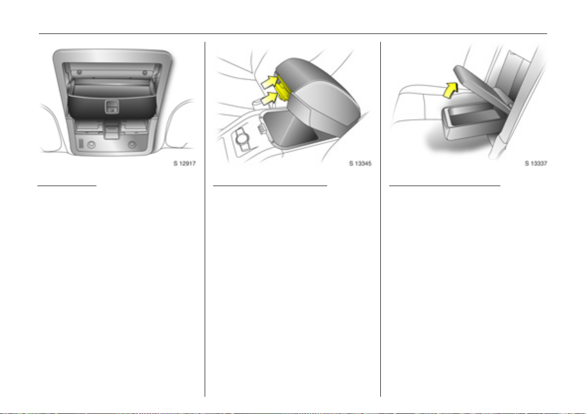
Seats, interior 65
Back to overview
Sunglass holder
To open: push the rear part of the front
reading lamps cover.
To close: pull up cover and push it until it
latches into place.
Do not store heavy items in the stowage
compartment.
Console box in front
armrest 3
To open: pull up lower lever and lift the lid.
To close: lower lid and push it down until it
latches into position.
To use the tray 3: ensure armrest is in its
rearmost position, pull up on upper lever
and lift the lid.
Console box in rear armrest
3
To open: pull up lid of rear centre armrest.
To close: lower lid and push it down until it
latches into position.
Page 66

Seats, interior66
Back to overview
Console net 3
Located in the front passenger’s footwell.
Front pa
ssenger’s seat undertray 3
Pull up on front of tray then pull it forwards.
Push the tray towards the seat to return it
to its original position.
Storage compartment
3
Located in rear of centre console.
To open: press button above the storage
compartment.
Page 67

Seats, interior 67
Back to overview
Card holder
Located below instrument panel on driver’s
side. Insert a card into the slot for
convenient use.
Coin storage
Open by pulling handle on coin storage
door (located below card holder) towards
you. Push door firmly to close.
Ashtrays 3
To be used only for ash and not for
combustible rubbish.
9 Warning
Disregard of these instructions may lead
to injuries or endanger life. Vehicle
passengers must be informed
accordingly.
Drink holders
Located in the front 3 and rear of the
centre console.
The front drink holder is a fixed size.
The rear drink holder is flexible, allowing
different size drink containe rs to be s tored.
To open: press button above rear drink
holder.
Page 68

Seats, interior68
Back to overview
Warning triangle ¨ 3,
First aid kit + 3
Your first aid kit and warning triangle can
be accommodated below the floor cover in
the luggage compartment.
Portable front ashtray 3
Located in front drink holder.
To open: gently lift up lid. Illuminates
depending on outside light conditions.
To empty: rotate upper part of ashtray
anti-clockwise and remove.
After use, close lid firmly.
To replace battery: remove screw on
ashtray lid and replace with CR2032
(or equivalent) battery.
Power outlets
Cigarette lighter )
With ignition switch in positions ACC or ON,
push the cigarette lighter in all the way.
Heating up ceases once element is
glowing; cigarette lighter pops up
automatically. Withdraw lighter.
Page 69

Seats, interior 69
Back to overview
Accessory sockets
Located in the rear centre console between
the front seats and in the right-hand side of
the luggage compartment 3.
Operational with ignition switch in
positions ACC or ON.
Pull the cap out to use the accessory
socket, and replace it when not in use.
The socket for the cigarette lighter can also
be used to connect electrical accessories
when the ignition is switched on.
Use of accessory sockets while the engine is
not running will discharge the battery.
The maximum power requirement of
electrical accessories must not exceed
120 watts.
Do not connect any current delivering
accessories, e.g. electrical charging
devices or batteries.
Connected electrical accessories must
comply with the EC standard in terms of
electromagnetic compatibility
requirements laid down in DIN VDE 40 839,
otherwise vehicle malfunctions may occur.
The use of non-authorised accessories may
cause damage to the socket.
Assist grips
Located above the driver’s door 3, the
front passenger’s door and both rear
doors.
Pull grip down and hold to assist when
entering or exiting the vehicle. Grips swing
back up automatically when released.
Rear door assist grips also include coat
hangers.
Page 70

70 Instruments, controls
Back to overview
Instruments, controls
Control indicators ............................... 70
Instrument display.............................. 75
Information display ............................ 76
Display of current tyre pressure 3 .... 91
Check control 3 .................................. 91
Warning buzzers................................. 92
Windscreen wipers.............................. 92
Control indicators
The control indicators described here are
not present in all vehicles. The description
applies to all instrument versions.
The colours of the control indicators mean:
z Red Danger, important reminder,
z Yellow Warning, information, fault,
z Green Confirmation of activation,
z Blue Confirmation of activation.
u
ABS (Anti-lock Brake System)
see page 148.
4
Brake system
Illuminates in red when ignition is switched
on. Extinguishes after engine is started.
Illuminates when engine is running if
hand brake is applied and/or fluid level for
brake hydraulics is too low.
9 Warning
If it illuminates when the hand brake is
not applied: stop vehicle; interrupt your
journey immediately. Consult a
workshop.
g
Trailer indicator 3
Illuminates in green when a trailer is
connected to the vehicle. Extinguishes
when the trailer is disconnected.
Further information - see page 145.
Page 71

Instruments, controls 71
Back to overview
r
Park pilot 3
Illuminates in yellow when ignition is
switched on, then extinguishes.
If it stays illuminated while driving, there is
a fault in the system - see page 142.
5
DCS (Descent Control System)
Both control indicators illuminate when
ignition is switched on, then extinguish.
; illuminates when DCS is ready for
Green
operation. Flashes during driving when
DCS is in operation, after pressing the
DCS button.
; flashes to indicate system is not
Yellow
ready for conditions to operate.
Illuminates to indicate there is a fault in the
system.
If the yellow control indicator flashes or
illuminates during driving, friction material
needs to cool down: drive the vehicle
without braking as much as possible.
Further information - see page 138.
B
AWD (All Wheel Drive)
Illuminates in yellow when ignition is
switched on, then extinguishes.
If it flashes during driving, the AWD system
is temporarily disabled.
If it illuminates, there is a fault in the
system. Consult a workshop as soon as
possible.
Further information - see page 121.
7
ESC Active & Warning
(Electronic Stability Control)
see page 136.
A
ESC Not Ready
see page 136.
J
ESC OFF
see page 136.
q
Automatic headlamp range
adjustment 3
Illuminates in yellow when ignition is
switched on, then extinguishes.
Comes on during driving to indicate a fault
that requires immediate attention. Consult
a workshop as soon as possible.
Further information - see page 97.
W
Coolant temperature
Illuminates in red when ignition is
switched on, then extinguishes.
If it illuminates when the engine is running
stop vehicle and switch off engine. Coolant
temperature is too high; danger of engine
damage. Check coolant level.
9 Warning
Allow engine to cool down before
removing coolant filler cap.
Further information - see page 195.
:
Page 72

Instruments, controls72
Back to overview
o
Electronic immobiliser
Illuminates in red when ignition is
switched on, then extinguishes.
If it remains illuminated after the ignition is
on, there is a fault in the immobiliser
system; the engine cannot be started see page 22.
9
Door open
Illuminates in red when a door is open.
3
Engine electronics,
transmission electronics 3
Illuminates in yellow when ignition is
switched on, then extinguishes.
If it illuminates
there may be a fault in the engine or
transmission electronics: interrupt your
journey and consult a workshop as soon as
possible.
Further information - see page 134.
during driving;
v
Airbag systems 3, belt tensioners
see pages 44, 52.
1
Tailgate open
Illuminates in red when ignition is
switched on, then extinguishes.
Illuminates when tailgate is open or not
securely latched.
Tailgate - see page 26.
X
Driver’s seat belt reminder
Illuminates in red when ignition is
switched on, then extinguishes.
When the engine is running, if driver’s seat
belt is not engaged, it will flash for approx.
90 seconds and then illuminate until
driver’s seat belt is fastened.
If vehicle speed exceeds approx. 22 km/h
(14 mph), control indicator will flash for
approx. 90 seconds along with a warning
chime and then remains illuminated until
driver’s seat belt is fastened.
Seat belts - see page 43.
O
Turn signal lamps
The relevant control indicator flashes in
green when the turn signal is on.
Rapid flash; failure of a turn signal bulb or
the corresponding fuse or failure of a trailer
turn signal bulb 3. Both control indicators
flash when the hazard warning lamps are
active.
Further information - see pages 14, 95.
Bulb replacement - see page 185.
Fuses - see page 181.
Y
Low fuel level
Illuminates in yellow when ignition is
switched on, then extinguishes.
If it illuminates during driving; fuel level low:
fill up fuel tank as soon as possible.
Never let the tank run dry.
Erratic fuel supply can cause catalytic
converter to overheat - see page 133.
Diesel engines: if the tank has been run dry,
bleed the fuel system as described on
page 171.
Refuelling - see page 132.
Fuel tank capacity - see page 225.
Page 73

Instruments, controls 73
Back to overview
>
Front fog lamps
Illuminates in green when front fog lamps
are switched on - see page 96.
r
Fog tail lamp
Illuminates in yellow when the fog tail lamp
is switched on - see page 96.
P
Headlamp main beam
Illuminates in blue when main beam is on
and when headlamp flash is operated see pages 14, 95.
G
Low windscreen washer fluid
Illuminates in yellow when ignition is
switched on, then extinguishes.
If it illuminates: windscreen washer fluid
level low, add washer fluid as soon as
possible - see page 199.
N
Water in diesel fuel filter 3
Illuminates in yellow when water level in
diesel fuel filter exceeds a specified level.
Residual water in the diesel fuel filter will
need to be drained - see page 194. Consult
a workshop as soon as possible.
C
Change engine oil 3
Illuminates in yellow when ignition is
switched on, then extinguishes.
Illuminates to indicate that engine oil
needs changing within approx. 1000 km
(600 miles). Engine power may be
decreased.
Once the engine oil has been changed, the
engine oil life monitor needs to be reset see page 194.
N
Preheating for diesel engines 3
Illuminated in yellow during preheating.
Preheating system switches on only if
outside temperature is low.
If it comes on during driving or if the engine
cannot be started, consult a workshop as
soon as possible.
Starting the engine - see page 19.
I
DPF (Diesel particle filter) 3
Illuminates in yellow when diesel particle
filter requires cleaning.
As soon as the road and traffic situation
permits it, increase speed to more than
50 km/h (30 mph) for approx. 15 minutes.
The control indicator extinguishes as soon
as cleaning is complete.
Further information - see page 135.
m
Cruise control 3
see page 140.
S
Engine oil level 3
Illuminates in yellow when ignition is
switched on, then extinguishes.
If it illuminates during driving;
oil level low: top up oil to specified level see page 192.
2
Power steering
Illuminates in yellow when ignition is
switched on, then extinguishes.
If it does not illuminate when the ignition is
switched on, stays illuminated or
illuminates during driving, there is a fault in
the system. Consult a workshop as soon as
possible.
Page 74

Instruments, controls74
Back to overview
a
Anti-theft alarm system activation
without monitoring of passenger
compartment and vehicle tilt 3
see page 28.
I
Engine oil pressure
Illuminates in red when ignition is switched
on. Extinguishes after engine is started.
Can illuminate intermittently when idling
with hot engine; must extinguish when
engine speed is increased.
it illuminates during driving;
If
engine oil pressure may be dangerously
low, interrupting engine lubrication and
resulting in damage to the engine and/or
locking of the driving wheels:
z Move out of the flow of traffic as quickly
as possible without impeding other
vehicles,
z Depress clutch,
z Move gearshift lever to neutral
(automatic transmission to N),
z Switch off ignition.
9 Warning
When the engine is off, considerably
greater force will be required for braking
and steering.
Do not remove key until vehicle has come
to a standstill, otherwise the steering
column lock could engage unexpectedly.
Check engine oil level before consulting
a workshop. If the oil level is low, top up
using the specified engine oil - see pages
192, 213, 217.
If the oil level is normal, have a workshop
check the vehicle’s lubricating system.
p
Alternator
Illuminates in red when ignition is switched
on. Extinguishes after engine is started.
it illuminates during driving:
If
stop vehicle and switch off engine. The
battery is not being charged and the
engine cooling may be interrupted. The
brake servo unit may cease to be effective.
Interrupt your journey immediately.
Remove key and check drive belt condition
and tensioning before consulting a
workshop.
Z
Exhaust emissions
Illuminates in yellow when ignition is
switched on. Extinguishes after engine is
started. Can illuminate briefly when
driving; this is normal and does not
indicate a system fault.
If it illuminates when the engine is running
fault in emission control system.
The permitted emission limits may be
exceeded. Fuel economy and vehicle
driveability may be impaired.
The control indicator also illuminates if
there is a fault in the diesel particle filter 3.
Consult a workshop as soon as possible.
If it flashes when the engine is running
for a fault that can lead to destruction of
the catalytic converter, see page 134.
Consult a workshop as soon as possible.
0
Winter program 3
Illuminates in yellow when Winter program
for the automatic transmission is enabled see page 117.
;
;
Page 75

Instruments, controls 75
Back to overview
Instrument display
Tachometer
Making use of the tachometer helps to
save fuel; it indicates the engine speed in
revolutions per minute (rpm).
Red warning zone on right; maximum
permissible engine speed exceeded,
danger to engine.
If possible, drive in each gear in the low
engine speed range (between approx.
2000 and 3000 rpm) and maintain an even
vehicle speed to maximise fuel efficiency.
Speedometer
Indicates the vehicle speed.
Odometer
The odometer indicates how far the vehicle
has been driven.
Trip odometer
There are two independent trip odometers
which indicate how far the vehicle has been
driven since the last reset.
Press the trip odometer button once to
toggle between Trip A and Trip B.
To reset a trip odometer, press and hold
the trip odometer button.
Page 76

Instruments, controls76
Back to overview
11:25} 21.5°C
Range
RDS [TP]
257km
Fuel gauge
Indicates fuel level when the ignition is on.
After adding fuel and restarting engine,
fuel gauge pointer slowly moves to show
new fuel level.
When fuel gauge indicates that fuel supply
is low, control indicator
fill up fuel tank as soon as possible see page 132.
Never let the fuel tank become empty.
Diesel engines: if the tank has been run dry,
bleed the fuel system as described on
page 171.
Because of the amount of fuel remaining in
the tank, the amount of fuel required to fill
the tank may be less than the specified
tank capacity.
Y illuminates:
Transmission display 3
Display of the selected gear or mode with
automatic transmission 3.
P
R
N
D
1 to 5
Park position.
Reverse gear.
Neutral.
Automatic mode.
Selected gear in manual
mode.
Information display
Board information display
Display of time, outside temperature and
date/Infotainment system (when it is on).
An F in the display indicates a fault.
Have the cause of the fault remedied by a
workshop.
Page 77

Range
Back to overview
Aver. Consump.
Inst. Consumpt.
19,5° 19:36
257
7.0
7.6
km
Ltr./100km
Ltr./100km
The type of information and how it is
displayed depends on the equipment of
the vehicle and the settings of the trip
computer 3 and Infotainment system.
Some information appears on the display
in an abbreviated form.
Infotainment system – see Infotainment
system instruction manual.
An F in the display indicates a fault.
Have the cause of the fault remedied by a
workshop.
Instruments, controls 77
:
11:25} -1.5°C
Range
RDS [TP]
257km
Graphical information display 3,
colour information display 3
Display of time, outside temperature, and
date/Infotainment system (when it is on).
The graphical information display presents
the information in monochrome. The colour
information display presents the
information in colour.
Outside temperature
A fall in temperature is indicated
immediately and a rise in temperature
after a time delay.
If outside temperature drops to 3 °C,
the symbol : illuminates in the board
information display as a warning for
icy road surfaces. : remains illuminated
until outside temperature reaches at
least 5 °C.
Page 78

Instruments, controls78
Back to overview
11:25} 21.5°C
Slippery road
-2,5°C
OK
In vehicles with graphical information
display 3 or colour information display 3,
a warning message appears on the display
as a warning for icy road surfaces. There is
no message below -5 °C.
9 Warning
Caution: the road surface may already
be icy, even though the display indicates
a few degrees above 0 °C.
Range
257km
Board information display,
selecting functions
Functions and settings of some equipment
can be accessed via the board information
display.
This is done via the menus and the buttons
on the Infotainment system or with the left
adjuster wheel on the steering wheel. The
relevant menu options are then shown on
the subsequent row of the display.
Select menu items using the arrow buttons:
OK button Select marked item,
confirm command.
Page 79

11:25} 21.5°C
Back to overview
System
Instruments, controls 79
The functions are displayed in the following
order:
z Time synchronisation
z Time, setting hours
z Time, setting minutes
z Date, setting day
z Date, setting month
z Date, setting year
z Ignition logic
z Language selection
z Setting units of measure
To select using the left adjuster wheel on
the steering wheel:
Turn up Previous menu item.
Turn down Next menu item.
Press Select marked item,
confirm command.
If check control 3 issues a warning
message, the display is blocked from other
functions. Acknowledge the message by
pressing the OK button or the left adjuster
wheel. If there are several warning
messages, acknowledge them one at a
time.
Board information display,
system settings
Press the Settings button on the
Infotainment system. Menu item Audio or
System will appear.
Press the left arrow button to reach menu
item System and select. The first function
of the System menu is marked.
Some of the functions appear on the
display in an abbreviated form.
Page 80

Instruments, controls80
Back to overview
11:25} 21.5°C
Clock Sync.On
Correcting time
Some RDS1) transmitters do not send a
correct time signal. If the incorrect time is
continually displayed, deactivate
automatic time synchronisation 3 and set
the time manually – see next column.
The automatic setting is indicated by } in
the display.
To correct time with the help of RDS, select
the menu item for time synchronisation
from the Settings menu.
Make the desired setting.
Setting date and time
Select the menu item for time and date
setting from the Settings menu.
Make the desired setting.
The setting is saved when the menu item is
exited.
Ignition logic
See Infotainment system instruction
manual.
3
11:25} 21.5°C
English
Language selection
You can select the display language for
some functions.
Select the menu item for language from the
Settings menu and make the desired
setting.
1)
RDS = Radio Data System.
Page 81

11:25} 21.5°C
Back to overview
Unit Europe-SI
Setting units of measure
You can select which units of measure are
to be used.
Select the menu item for units of measure
from the Settings menu and make the
desired setting.
Board information display,
trip computer 3
The trip computer provides information on
driving data, which is continually recorded
and evaluated electronically.
Access trip computer vehicle data by
pressing the BC button on the Infotainment
system or the left adjuster wheel on the
steering wheel.
Some of the functions appear on the
display in an abbreviated form.
Once a function has been selected, the
subsequent rows of the trip computer
function are displayed.
The functions are displayed in the following
order:
z Instantaneous consumption
z Average consumption
z Effective consumption
z Average speed
z Distance travelled
z Range
z Stop watch
Instruments, controls 81
11:25} 21.5°C
Inst. Consumpt.
7.6l/100km
Instantaneous consumption
Display changes depending on speed;
Display in l/h below 13 km/h.
Display in l/100 km above 13 km/h.
Page 82

Instruments, controls82
Back to overview
Average consumption
Display of average consumption.
The measurement can be restarted at any
time – see "Resetting trip computer
information".
Effective consumption
Displays amount of fuel consumed.
The measurement can be restarted at any
time – see "Resetting trip computer
information".
Average speed
Display of average speed.
The measurement can be restarted at any
time - see "Resetting trip computer
information".
Stoppages in the journey with the ignition
off are not included in the calculations.
Distance travelled
Displays number of kilometres (miles)
driven. The measurement can be restarted
at any time – see "Resetting trip computer
information".
11:25} 21.5°C
Range
257km
Range
Range is calculated from current fuel tank
content and instantaneous consumption.
The display shows average values.
The vehicle updates the range
automatically after a brief delay when the
vehicle has been refuelled.
If the fuel in the tank will allow less than
50 km (30 miles) of travel, the warning
"Range" appears on the display.
If the fuel in the tank will allow less than
30 km (20 miles) of travel, the warning
"Refuel!" 3 appears on the display.
Resetting trip computer information
The following trip computer information
can be reset (restart measurements):
z Average consumption
z Effective consumption
z Average speed
z Distance travelled
Select the desired trip computer
information.
Reset by pressing the left adjuster wheel on
the steering wheel or the OK button on the
Infotainment system.
Page 83

11:25} 21.5°C
Back to overview
Stop Watch
Interruption of power supply
If the power supply has been interrupted or
if the battery voltage has dropped too low,
the values stored in the trip computer will
be lost.
Instruments, controls 83
Range
Aver. Consump.
257
7.0
km
Ltr./100km
01:22:32h
Stop watch
Operating using the arrow buttons:
To start, press left arrow button to select
menu item Start and press OK button to
start/stop.
To reset, press left arrow button to select
menu item Reset and press OK button.
Operating using the left adjuster wheel on
the steering wheel:
To start, select menu item Start and press
to start/stop.
To reset, select menu item Reset and press
to confirm command.
Inst. Consumpt.
19,5° 19:36
Graphical information display 3 or
colour information display 3,
selecting functions
The functions and settings of some
equipment 3 can be accessed via the
graphical information display or the
colour information display.
Functions are selected and executed in the
menu on the display using the arrow
buttons 3, the multifunction knob 3 on the
Infotainment system or the left adjuster
wheel on the steering wheel.
7.6
Ltr./100km
Page 84

Instruments, controls84
Back to overview
To select using the arrow buttons:
Select menu items via menus and with
the buttons on the Infotainment system.
If check control 3 issues a warning
message, the display is blocked from other
functions. Acknowledge the message by
pressing the right or left arrow button. If
there are several warning messages,
acknowledge them one at a time.
To select using the multifunction knob:
Turn Mark menu items or
commands, select functions.
Press Select marked item, confirm
command.
To exit a menu, turn the multifunction knob
left or right to Return or Main and select.
If check control 3 issues a warning
message, the display is blocked from other
functions. Acknowledge the message by
pressing the multifunction knob.
If there are several warning messages,
acknowledge them one at a time.
To select using the left adjuster wheel on
the steering wheel:
Turn up Previous menu item.
Turn down Next menu item.
Press Select marked item,
confirm command.
If check control 3 issues a warning
message, the display is blocked from other
functions. Acknowledge the message by
pressing the left adjuster wheel. If there are
several warning messages, acknowledge
them one at a time.
Page 85

Instruments, controls 85
Back to overview
FM [TP] CDin
90.6
MHz
19,5° 19:36
For each functional area there is a main
page (Main), which is selected at the
top edge of the display:
z Audio
z Navigation 3
z Telephone 3
z Trip computer 3
For audio, navigation 3 and telephone 3
functions – see Infotainment system
instruction manual.
7777 Settings 19,5° 19:36
Time, Date 19:36
Language
Units 10 . 07 . 2004
Contrast
Day / Night
6666 Ign. logic
Graphical information display 3 or
colour information display 3,
system settings
The settings are accessed via the Settings
menu.
Press the Main button 3 (not found on all
Infotainment systems) on the Infotainment
system (call up main display).
Press the Settings button on the
Infotainment system. On Infotainment
System CD 30, make sure no menu has
been selected.
The Settings menu is displayed.
7777 Time, Date 19,5° 19:36
Time 19:36
Date 10 . 07 . 2004
6666 Synchron. clock automatical.
Setting date and time
Select menu item Time, Date from the
Settings menu.
The menu for Time, Date is displayed.
Select the menu items required:
make the desired setting.
Page 86

Instruments, controls86
Back to overview
Correcting time 3
With the navigation system, date and time
are set automatically upon receipt of a
1)
satellite signal. If the displayed time
GPS
does not match local time, it can be
corrected manually or automatically by
receiving an RDS
Some RDS transmitters do not send correct
time signals. If the incorrect time is
displayed often, deactivate automatic
time synchronisation 3 and set the time
manually.
To correct time with the help of RDS, select
menu item Synchron. clock automatical.
from the Time, Date menu.
The box in front of Synchron. clock
automatical. will be ticked:
see Fig. 17340 T.
2)
time signal 3.
7777 Settings 19,5° 19:36
Time, Date
Language Deutsch
Units English
Contrast Español
Day / Night ...
6666 Ign. logic
Language selection
You can select the display language for
some functions.
Select menu item Language from the
Settings menu.
The available languages are displayed.
7777 13 Languages 19,5° 19:36
X Deutsch
English
Español
Nederlands
Français
Italiano
Select the desired language.
Selections are indicated by a 6 in front of
the menu item.
In systems with voice output 3, when the
language setting of the display is changed,
the system will ask whether the
announcement language should also be
changed – see Infotainment system
instruction manual.
1)
GPS = Global Positioning System,
satellite system for world-wide positioning.
2)
RDS = Radio Data System.
Page 87

Instruments, controls 87
Back to overview
7777 Settings 19,5° 19:36
Time, Date
Language
Units
Contrast
Day / Night
6666 Ign. logic
~ Europe-SI
| Japan
| Great Britain
| USA
Setting units of measure
You can select which units of measure are
to be used.
Select menu item Units from the Settings
menu.
The available units are displayed.
Select the desired unit.
Selections are indicated by a o in front of
the menu item.
7777 Contrast 19,5° 19:36
12
Adjusting contrast
(graphical information display)
Select menu item Contrast from the
Settings menu.
The menu for Contrast is displayed.
Confirm the required setting.
3
Setting display mode
3
The display can be adjusted to suit the light
conditions: black or coloured text on a light
background or white or coloured text on a
dark background.
Select menu item Day / Night from the
Settings menu.
The options are displayed.
Automatic; adapted based on vehicle
lighting.
Always day design; black or coloured text
on light background.
Always night design; white or coloured
text on dark background.
Selections are indicated by a o in front
of the menu item.
Ignition logic
3
See Infotainment system instruction
manual.
Page 88

Instruments, controls88
Back to overview
Ü Board Computer 19,5° 19:36
BC 1 All values
BC 2
Timer
Tyres
1111
257.0 km
Ø40km/h
31.0 Ltr.
8888
Ø 7.0 Ltr./100km
Range
Aver. Consump.
Inst. Consumpt.
19,5° 19:36
257
7.0
7.6
km
Ltr./100km
Ltr./100km
Range
33km
OK
Graphical information display 3 or
colour information display 3,
trip computer 3
The trip computers provide information on
driving data, which is continually recorded
and evaluated electronically.
The trip computer main page provides
information on range, average
consumption and instantaneous
consumption.
To display other trip computer data,
press the BC button on the Infotainment
system and select the trip computer menu
in the display.
Range
Range is calculated from current fuel tank
content and instantaneous consumption.
The display shows average values.
After refuelling, the vehicle updates the
range automatically after a brief delay.
If the fuel in the tank will allow less than
50 km (30 miles) of travel, the warning
"Range" appears on the display.
If the fuel in the tank will allow less than
30 km (20 miles) of travel, the warning
"Refuel!" 3 appears on the display.
Acknowledge the menu item as described
on page 84.
Instantaneous consumption
Display changes depending on speed;
Display in l/h below 13 km/h.
Display in l/100 km above 13 km/h.
Page 89

Distance travelled
Back to overview
Displays number of kilometres (miles)
driven. The measurement can be restarted
at any time - see "Resetting trip computer
information".
Average speed
Display of average speed.
The measurement can be restarted at any
time - see "Resetting trip computer
information".
Stoppages in the journey with the ignition
off are not included in the calculations.
Effective consumption
Displays amount of fuel consumed.
The measurement can be restarted at any
time - see "Resetting trip computer
information".
Average consumption
Display of average consumption.
The measurement can be restarted at any
time - see "Resetting trip computer
information".
Ü Board Computer 19,5° 19:36
BC 1 All values
BC 2
Timer
Tyres
1111
Ø40km/h
257.0 km
31.0 Ltr.
8888
Ø 7.0 Ltr./100km
Resetting trip computer information
The following trip computer information
can be reset (restart measurements):
z Distance travelled
z Average speed
z Effective consumption
z Average consumption
Select BC 1 or BC 2 from the trip computer
menu.
Instruments, controls 89
Ü Reset BC 1 19,5° 19:36
All values
257.0 km
Ø40km/h
31.0 Ltr.
Ø 7.0 Ltr./100km
The information of the two trip computers
can be reset separately, making it possible
to evaluate data from different time
periods.
Select the desired trip computer
information.
The value for the selected function will be
reset and recalculated.
Page 90

Instruments, controls90
Back to overview
Ü Reset BC 1 19,5° 19:36
All values
257.0 km
Ø40km/h
31.0 Ltr.
Ø 7.0 Ltr./100km
Interruption of power supply
If the power supply has been interrupted or
if the battery voltage has dropped too low,
the values stored in the trip computer will
be lost.
Ü Board Computer 19,5° 19:36
BC 1
BC 2
Timer
Tyres Start
00:00:00
Reset
Options
To reset all information of a trip computer,
select menu item All values.
After resetting, "- - -" is displayed for the
trip computer information selected. The
recalculated values are displayed after a
brief delay.
Stop watch
Select menu item Timer from the Board
Computer menu.
The Timer menu is displayed.
To start, select menu item Start.
To reset, select menu item Reset.
Page 91

Instruments, controls 91
Back to overview
The desired stop watch display can be
selected from the Options menu 3:
Driving Time excl. Stops
The time the vehicle is in motion is
recorded. Stationary time is not included.
Driving Time incl. Stops
The time the vehicle is in motion is
recorded. The time the vehicle is stationary
with the key in the ignition switch is
included.
Travel Time
Measurement of the time from manual
activation via Start to manual deactivation
via Reset.
Ü Board Computer
BC 1
BC 2
Timer
Tyres
Display of current tyre pressure 3
Select menu item Tyres from the Board
Computer menu.
The current pressure of each tyre is
displayed.
Further information – see page 144.
Check control 3
In vehicles with tyre pressure monitoring
system 3, if tyre pressure is too low, the
display indicates which tyre to check, e.g.:
Tyre pressure
check rear
right tyre
(value in bar)
Check tyre pressure at next opportunity
using suitable gauge.
Tyre pressure monitoring system 3 –
see page 144.
Tyre pressure – see page 224.
In vehicles with tyre pressure monitoring
system 3, if there is a major loss of pressure
in a tyre, the display indicates the tyre at
fault, e.g.:
Attention!
Rear left tyre
pressure loss
(value in bar)
Stop immediately and check tyre.
Tyre pressure monitoring system 3 –
see page 144.
Tyre pressure – see page 224.
Page 92

Instruments, controls92
Back to overview
Warning buzzers
While driving:
z when operating the turn signals.
z if driver’s or passenger’s seat belt 3 is
not engaged when the seat is occupied
and vehicle speed exceeds approx.
22 km/h (14 mph).
When the vehicle is parked and driver’s
door is opened:
z with exterior lamps switched on.
z when the key is in the ignition switch.
6 Seat belt warning chimes -
see pages 46, 72,
driving hints - see page 127,
save fuel, protect the environment see page 129.
Windscreen wipers
To activate, move lever upwards.
J =Off
$ =Timed interval wipe
% =Slow
& =Fast
Press lever down from position J:
single swipe.
Further information - see pages 198, 202,
205.
Adjustable wiper interval
To set the wiping interval to a value
between 1 and 10 seconds:
Switch on ignition.
Push lever down from position J.
Wait the desired interval.
Set the lever to adjustable timed interval
wiper position $.
The interval remains stored until the next
change or the ignition is switched off.
Switching the ignition on and moving the
lever to $ sets the interval to 3.5 seconds.
In this mode, wiping frequency is also
affected by vehicle speed. As vehicle speed
increases, wiping will become more
frequent.
Page 93

Instruments, controls 93
Back to overview
Automatic wiping with rain sensor 3
To activate, move lever upwards to
automatic wiping with rain sensor
position $.
The rain sensor detects the amount of
water on the windscreen and automatically
regulates the windscreen wipers.
The wipers operate for one cycle to check
the system when the ignition switch is
turned to ACC.
To turn wipers off, move lever to position J.
Keep the rain sensor area clean by
activating the windscreen washer system.
Further information - see pages 198, 202,
205.
Windscreen and headlamp washer
systems 3
To activate, pull lever towards steering
wheel. Washer fluid is sprayed onto the
windscreen. If the lever is held longer, the
wipers operate for two cycles after the lever
has been released and once more after a
3 second delay 3.
The headlamp washer system 3 can only
be operated when the headlamps are on.
Washer fluid is sprayed onto the
headlamps. The headlamp washer system
can only be operated again after a short
delay. If washer fluid level is low then this
delay is increased.
On vehicles fitted with rain sensor 3, keep
the sensor area clean by activating the
windscreen washer system.
Further information - see pages 199, 202,
205.
Tailgate wiper and washer systems
Activate wipers and washer as follows:
Wipers on = Push lever forwards
Wipers off = Pull lever back towards
steering wheel
Wash = Press and hold button
Washer fluid is sprayed on to tailgate
window when the button on the end of the
lever is pressed. When the button is
released, the washer will stop, but the
wipers will continue to swipe for approx.
3cycles.
Further information - see pages 198, 199,
202, 205.
Page 94

Lighting94
Back to overview
Lighting
Main beam, headlamp flash ............. 95
Automatic dipped beam activation 3 95
Turn signal lamps ............................... 95
Front fog lamps > ............................. 96
Fog tail lamp r .................................. 96
Reversing lamps.................................. 96
Centre high-mounted stop lamp....... 96
Hazard warning lamps ...................... 97
Headlamp range adjustment q........ 97
Peripheral lighting .............................. 98
Instrument illumination, information
display illumination.......................... 98
Interior courtesy lamps....................... 98
Battery discharge protection............. 100
Headlamps when driving abroad ..... 100
Exterior lamps
Turn light switch:
7 =Off
8 = Parking lamps
9 = Dipped beam or main
beam
AUTO = Automatic dipped beam
activation 3
In positions 8 and 9, the tail lamps,
license plate lamps and instrument panel
lamps are also on.
Daytime running lamps 3
Come on automatically when engine is
started.
They will turn off when the parking lamps
or dipped beam are on, or when the engine
is stopped.
Follow the regulations of the country in
which you are driving when using daytime
running lamps and front fog lamps.
Driving abroad - see page 100.
Lamps on reminder
If the driver’s door is opened when the light
switch is in position 8 or 9 and the
ignition is off, a warning chime will sound.
If the lamps are then switched off and back
on again, the warning chime will not sound.
Wiper activated lighting 3
With light switch in AUTO position,
if windscreen wipers are operated for
8 cycles or more, the exterior lamps
illuminate automatically.
Approach lighting 3
Depending upon outside light conditions,
when you press q on the remote control,
the hazard warning lamps flash twice and
the exterior lamps illuminate for approx.
20 seconds.
Page 95

Lighting 95
Back to overview
Main beam, headlamp flash
To switch from dipped beam to main
beam, push lever forwards.
To switch back to dipped beam, pull lever
back towards steering wheel.
To activate the headlamp flash, pull lever
towards steering wheel. Main beam is
engaged for the duration of activation.
The blue control indicator P is illuminated
when main beam or headlamp flash is on.
Automatic dipped beam
activation 3
Light switch to AUTO; dipped beam comes
on automatically when the engine is
running, depending on outside light
conditions.
For reasons of safety, the light switch
should always remain in the AUTO
position.
To ensure automatic dipped beam
activation functions properly, do not cover
the light sensor on top of the instrument
panel.
Turn signal lamps
To activate, press lever up or down lightly.
Lever up = Right turn
Lever down = Left turn
When the steering wheel is turned back, the
lever automatically returns to its rest
position. This will not happen when making
a minor steering manoeuvre such as lane
changing.
Tap signal: briefly move lever to resistance
point. The turn signal then flashes three
times when changing lanes or the like.
Hold the lever if you want the turn signals
to flash for longer. When released, the lever
will spring back to rest position.
The volume of the turn signal lamps’
audible warning is dependent upon vehicle
speed.
Page 96

Lighting96
Back to overview
Reversing lamps
Come on when reverse gear is engaged
and ignition is switched on.
Centre high-mounted stop lamp
Comes on when the brakes are applied,
acting as a third stop lamp, to supplement
the brake lamps.
Front fog lamps
On = Press button >, >
illuminates in instrument
panel.
Off = Press button > again, >
extinguishes in instrument
panel.
The front fog lamps can only be switched
on when both the ignition and headlamps
are on.
With automatic dipped beam activation 3,
parking lamps and dipped beam come on
simultaneously when the front fog lamps
are switched on.
Follow the regulations of the country in
which you are driving when using front fog
lamps.
>
Fog tail lamp r
On = Press button r, r
illuminates in instrument
panel.
Off = Press button r again, r
extinguishes in instrument
panel.
The fog tail lamp can only be switched on
when the ignition is on and the light switch
is in position 9, or the front fog lamps are
on and the light switch is in position 8.
With automatic dipped beam activation 3,
parking lamps and dipped beam come on
simultaneously when the fog tail lamp is
switched on.
Page 97

Hazard warning lamps
Back to overview
To switch on, press button ¨.
To switch off, press button ¨ again.
To aid location of the pushbutton, the red
surface is illuminated when the ignition is
switched on. When the button is pressed,
its control indicator flashes in unison with
the hazard warning lamps.
Headlamp range adjustment q
Manual headlamp range adjustment 3
With dipped beam switched on, adjust
headlamp range to suit vehicle load.
Correct adjustment of the headlamp range
reduces dazzle for other road users.
Automatic level control system 3 see page 143.
Vehicles without level control system
z Front seats occupied = 0
z All seats occupied = 1
z All seats occupied and load in
luggage compartment
z Driver’s seat occupied and load
in luggage compartment
=2
=3
Lighting 97
Vehicles with level control system
z Front seats occupied = 0
z All seats occupied = 1
z All seats occupied and load in
luggage compartment
z Driver’s seat occupied and load
in luggage compartment
Automatic headlamp range
adjustment 3
On vehicles with Xenon headlamps, the
range of the headlamps is adjusted
automatically based on vehicle load.
If control indicator q for automatic
headlamp range adjustment illuminates in
the instrument panel while driving, a fault
has occurred.
Have the cause of the fault remedied
immediately. Consult a workshop.
=1
=2
Page 98

Lighting98
Back to overview
Peripheral lighting
The dipped beam and reversing lamps
illuminate for approx. 30 seconds after the
driver exits the vehicle and closes the door.
To activate function:
1. Switch off ignition.
2. Remove ignition key.
3. Open driver’s door.
4. Pull turn signal lever towards
steering wheel.
If the driver’s door is left open, the lamps
will extinguish after two minutes.
Peripheral lighting can be deactivated by
inserting the key in the ignition switch or by
pulling the turn signal lever towards the
steering wheel again while the driver’s door
is open.
Instrument illumination,
information display illumination
Comes on when ignition is switched on.
Brightness can be adjusted when the
exterior lamps are on: turn wheel to the
right or left until the desired brightness is
obtained.
If driver’s door is opened or q is pressed on
the remote control, instrument panel lamps
will illuminate automatically and stay on
for approx. 30 seconds until ignition switch
is turned to the ACC position.
Display mode 3 - see page 87.
Interior courtesy lamps
Front reading lamps, rear interior lamps
and luggage compartment lamps function
as courtesy lighting and illuminate when
the doors or tailgate are opened.
If doors or tailgate remain opened, the
lamps stay illuminated for approx.
10 minutes.
Once all doors and the tailgate are closed,
the courtesy lamps dim gradually after
approx. 10 seconds.
By pressing button d, both front reading
lamps and the rear interior lamps
illuminate.
Press the button again to turn the lamps
off.
Page 99

Lighting 99
Back to overview
Courtesy lamps can be turned off
immediately by pressing button
K.
Front reading lamps
Left and right reading lamps are
individually operable. With ignition on:
On = Press button L or M
Off = Press button again
9 Warning
Avoid using interior lamps while driving in
the dark, as they can reduce driver
visibility.
Rear interior lamps
Press button to turn on left and right rear
interior lamps individually.
Press button again to turn the lamp off.
Page 100

Lighting100
Back to overview
Luggage compartment lamps
Come on when a door or the tailgate is
opened.
Front door lamps
Come on when a door is opened.
Once all doors are closed, the front door
lamps extinguish after approx. 10 seconds.
If the doors are left open, the lamps will
stay on for approx. 10 minutes.
Front door lamps can also be turned off
immediately by pressing button
roof lining.
Ignition switch illumination
Comes on when you open a door.
Ignition switch illumination can also be
turned off immediately by pressing
K in the roof lining.
button
Sun visor lamps 3
Come on when vanity mirror covers are
opened. See page 34.
Ashtray illumination
The portable front ashtray, located in the
front drink holder, illuminates depending
on outside light conditions. See page 68.
Glove compartment illumination
Comes on when the glove compartment is
opened. See page 64.
K in the
Battery discharge protection
To prevent battery from becoming
discharged, the external lamps turn off
automatically approx. 10 minutes after the
ignition is switched off.
Battery discharge protection will not work if
the lamps are turned on 10 minutes after
the ignition has been switched off; the key
cannot be removed from the ignition switch
until the battery is recharged.
Headlamps when driving abroad
The asymmetrical dipped beam increases
the field of vision on the near side of the
lane.
When driving in countries which drive on
the opposite side of the road, this causes
glare for oncoming traffic.
For temporary periods, to avoid glare the
headlamp pattern should be adjusted
down to the horizontal position.
Have the headlamps adjusted by a
workshop.
 Loading...