

Page 1

VAUXHALL Antara
Operation, Safety, Maintenance
Page 2

Data specific to your vehicle
Please enter your vehicle ’s data here t o ke ep it ea sily accessible.
This information is available under the section "Technical data " as well as on the identification plate and in the Service Booklet.
Fuel
Designati on
Engine oil
Grade
Viscosity
Tyre inflation pr essu re
Ty re size wi th up to 3 persons wi th full load, inc l. trail er
Summer tyres Front Rear Front Rear
Winter tyres Front Rear Front Rear
Weights
Permissible Gross Vehicle Weight
– EC kerbweight
=Loading
Page 3

Your Antara
is an intelligent combination of forwardlooking technology, impressive safety,
environmental friendliness and economy.
It now lies with you to drive your vehicle
safely and ensure that it pe rform s
perfectly. This Owner’s Manual provides
you with all the necessary information to
that end.
Make sure your passengers are aware
of the possible risk of accident and injury
which may result from improper use of the
vehicle.
You must always comply with the specific
laws of the country that y ou are travelling
through. These laws may differ from the
information in this Owner’s Manual.
When this Manual refers to a workshop
visit, we recommend your Vauxhall
Authorised Repairer.
All Vauxhall Authorised Re pairers provide
first-class service at reasonable prices.
You will receive quick, reliable and
indiv idual service.
Experienced mechanics, trained by
Vauxhall, work according to specific
Vauxhall instructions.
The O wner’s Ma nual sho uld alwa ys be kept
in the vehicle: Ready to hand in the glove
compartment.
Make us e o f the Own er’s Manual:
z The "In Brief" section will give you an
initial overview.
z The table of contents at the beginning
of the owner’s manual and within the
individual chapters will show you where
everything is.
z Its index will help you find what you
want.
z It will familiarise you with the
sophisticated technology.
z It will increase your pleasure in your
vehicle.
z It will help you to handle your vehicle
expertly.
The Owner’s Manual is designed to be
clearly laid-out and easily understood.
This s ym bol sign ifie s:
6 Continue read ing on next pa ge.
3 Items m arked with an asterisk are not
fitted to all vehicles (model variants,
engine op tions, mode ls specific to one
country, optional equipment, Genuine
Vauxhall Parts and Accessories).
9 Wa rnin g
Text marked 9 Warning provides
information on risk of accident or injury.
Disregard of the instructions may lead to
inju ries or endanger life.
Inform your passengers accordingly.
Yellow arrows in the illustrations serve as
points of reference or indicate some action
to be performe d.
Black arrows in the illustrations indicate
a reaction or a second action to be
performed.
Directional data, e.g. left or right, or front
or back, in the descriptions always relate to
the direction of travel.
We wish you many hours of pleasurable
driving
Your Vauxhall Team
Page 4

Page 5

1
Contents
Handling charact eri st ics
All Wheel Drive vehicles have a high centre
of gravity due to the increased ground
clearance required for off-road use.
As with other vehicles of this type, failure to
op erate the vehicle correctly may result in
loss of control or a n accident.
Please read the sections "Driving Hints"
on p age 122 and "All Wheel Drive" on
page 115.
Commitment to customer
satisfaction:
Our ai m: to k eep you happy with your
vehicle. All Vauxhall Authorised Repairers
offer first-class service at competitive
prices. Experienced, factory-trained
technicians work according to factory
instructions. Your Authorised Repairer can
supply you with GENUINE VAU XHALL-
APPROVED PARTS , which have undergone
stringent quality and precision checks, and
of course useful and attractive
VAUXHALL-APPROVED AC CESSORIES.
Our name is your guarantee!
For d eta ils of the
Vauxhall Authorised Rep aire r Ne tw ork,
please ring this number; 0845 090 2044
In b rief ....... ......... ........ ......... ......... ......... ......2
Instrum ents ... ..... ............. .... ......... ..... .... ... 2 2
Keys, doors, bonnet .. .............. .... ............ 46
Seats, interior ..... ........ ......... ......... ......... ... 5 6
Safety s ys tems ... .... ......... ......... ......... ....... 71
Lighting ..... ......... .... .... ......... ..... .... ......... ... 8 8
Windows, sunroof .. .... ......... ......... ......... ... 94
Climate c ontrol ...... ......... ......... ......... ....... 9 7
Au tomatic tran sm ission .......... .... ......... .109
All W heel Drive ...... .... ......... ......... ......... . 115
Driving hints .. ..... ........ ......... ......... ......... . 122
Save fue l, protec t the environment ..... 125
Fuel cons um ption, fuel, re fue lling ....... . 127
Catalytic converter,
exhaus t em issions ...... .... ......... ......... . 130
Drive control system s ......... ......... ......... . 134
Brake s ... ......... ......... ......... ......... ......... ..... 144
Whee ls, tyres ...... .... ......... .... .............. .... . 148
Roof racks,
caravan and trailer towin g . .... ......... .153
Self-help .... ......... .... .... ......... ..... ............. . 160
If you have a problem ... .... ..... ......... .... . 180
Service plan, m aintenance ..... .... ......... . 182
Vehicle care .. ......... .... .............. .... .......... 194
Te chnical data .. .... ......... .... .............. .... . 198
Index . .... ......... ......... ......... ......... ......... ..... 212
Page 6
In b rie f2
In brief
Picture no: s0013585.tif
Key nu mbers, code numbers
Remove key number from keys.
The key number is specified in the vehicle
documents and in the Car Pass 3.
Alloy whe els 3, towing equipment 3: make
a note of the key identifier codes.
Elec tronic imm obiliser, Infotainment
sy ste m 3: The code numb ers are spe cifie d
in the Car Pass.
Do not keep the Car Pass in the vehicle.
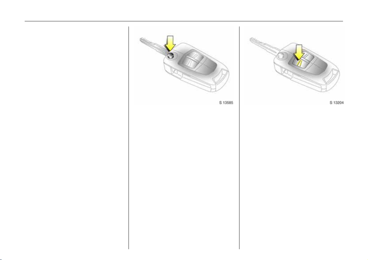
Ke y wi t h r e tr ac ta bl e k ey bl a de 3:
press button to extend.
6 Further information - see pag es 46, 47.
Picture no: s0013204.tif
To unlock and open the vehicle:
Press button q,
pull door handle
All doors, tailgate and tank flap are
unlocked.
6 Door locks - see page 24,
electronic immobiliser - see page 47,
radio frequency remote control see page 48,
ce ntral loc king sy ste m - see pa ge 5 0 ,
mechanical anti-theft locking system 3 -
see page 51,
Vauxhall alarm system 3 - see page 52.
Page 7
In brief 3
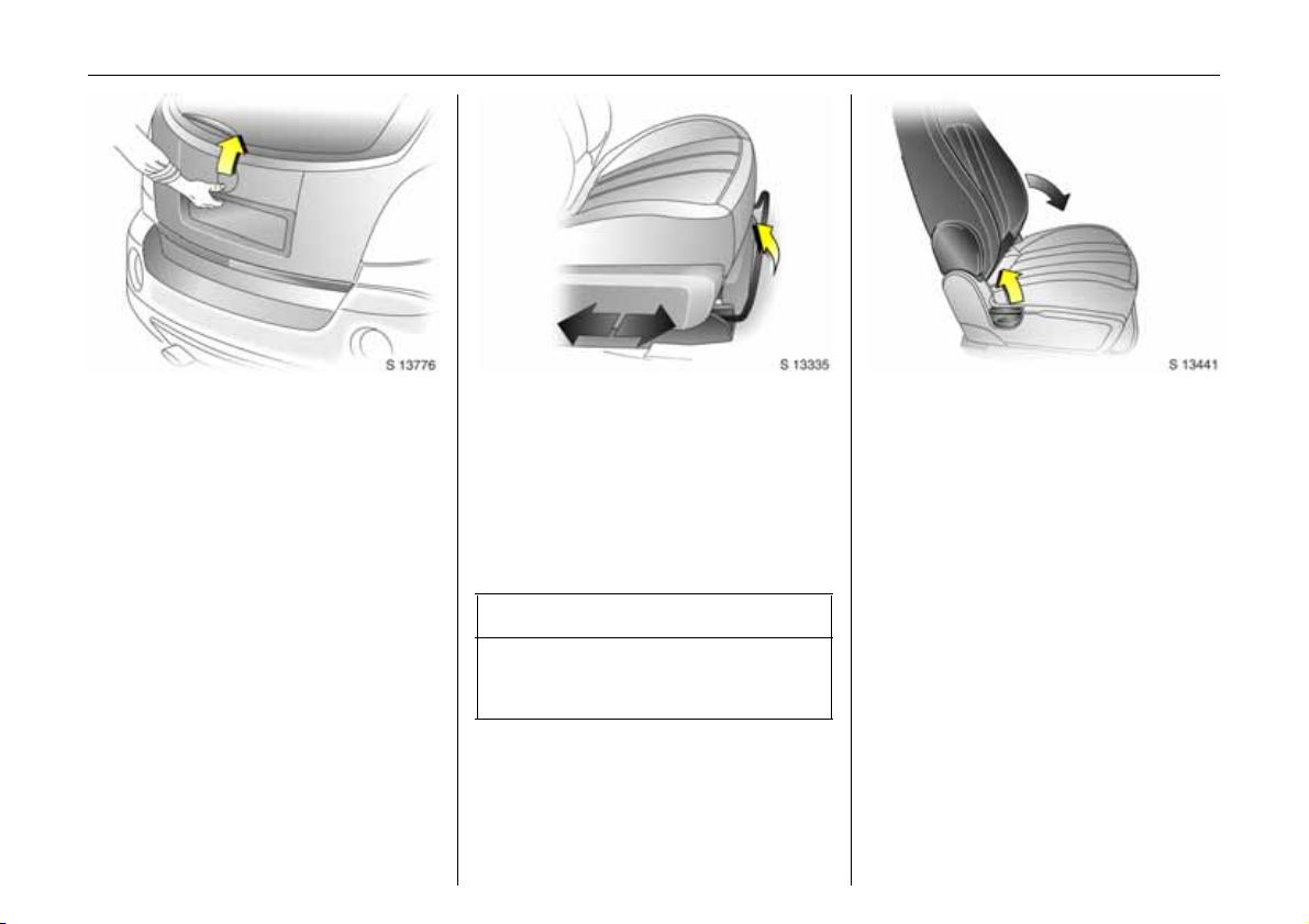
Picture no: s0013776.tif
To unl ock an d o pe n th e t ail ga te:
Press button q on remote co ntrol
and operate button beneath
handle
6 Tailgate - see page 54,
radio frequency remote control -
see page 48,
central locking system - see pag e 50,
Vauxhall alarm system 3 - see page 52.
Picture no: s0013335.tif
Front seat adjustment:
Pull h and le,
slide seat,
release handle
Nev er adjust the driver’s seat whilst driving.
It could move in an uncontrolled manner
when the handle has been pulled.
6 Seat position - see page 56.
9 Warning
Important: Do not sit nearer than
10 inches (25 cm) from the steering
wheel, to permit safe airbag deployment.
Picture no: s0013441.tif
Adjusting front seat backrests:
Lift release lever on outboard side
of seat
Move seat backrest to suit seating position
and lock in position when the lever is
released.
Do not lean on seat back rest whilst
adjusting it.
N eve r adjus t the driver’s se at whilst driving.
It could move in an uncontrolled manner
when the handle has been pulled.
6 Seat position - see pag e 56.
Page 8
In b rie f4
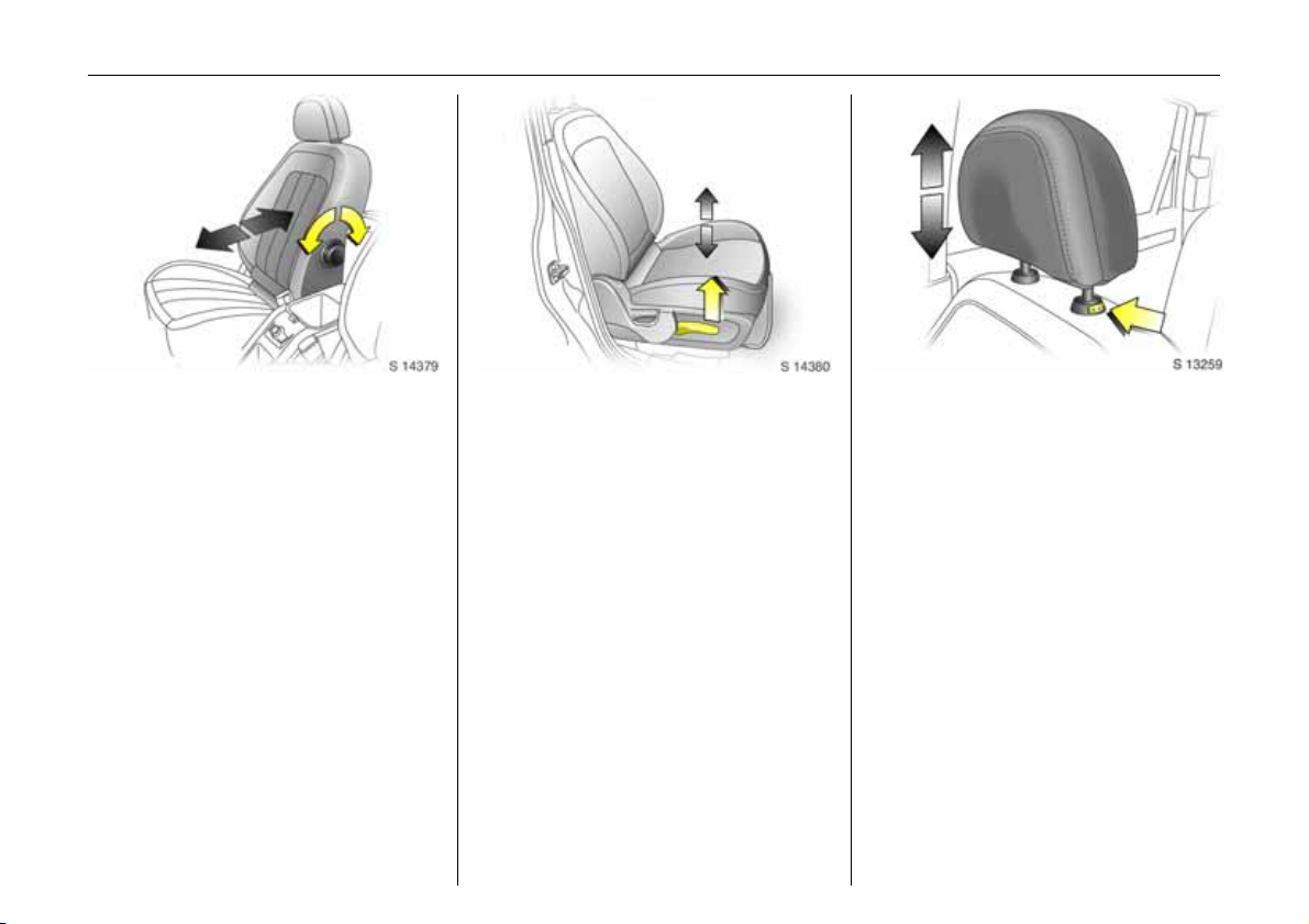
Picture no: s0013261.tif
A djusti ng the lumb ar sup po rt 3:
Turn handwheel
Adjust lumb ar support to suit personal
requirements.
Picture no: s0013605.tif
Adjusting seat height 3:
Raise or lower lever on side of
sea t
Lever pumping action
up war d: raises se at
downward: lowers seat
Nev er adjust the driver’s seat whilst driving.
It could move in an uncontrolled manner
wh en the le ver h as bee n operate d.
6 Seat position – see page 56.
Picture no: s0013259.tif
Adjusting head restraint height:
press release button,
adjust height to suit personal
requirements,
then release
Pull head restraint up to raise. Push d own
while pressing the release button to lower
the head restraint.
6 Head restraint position – see page 56.
Page 9
In brief 5
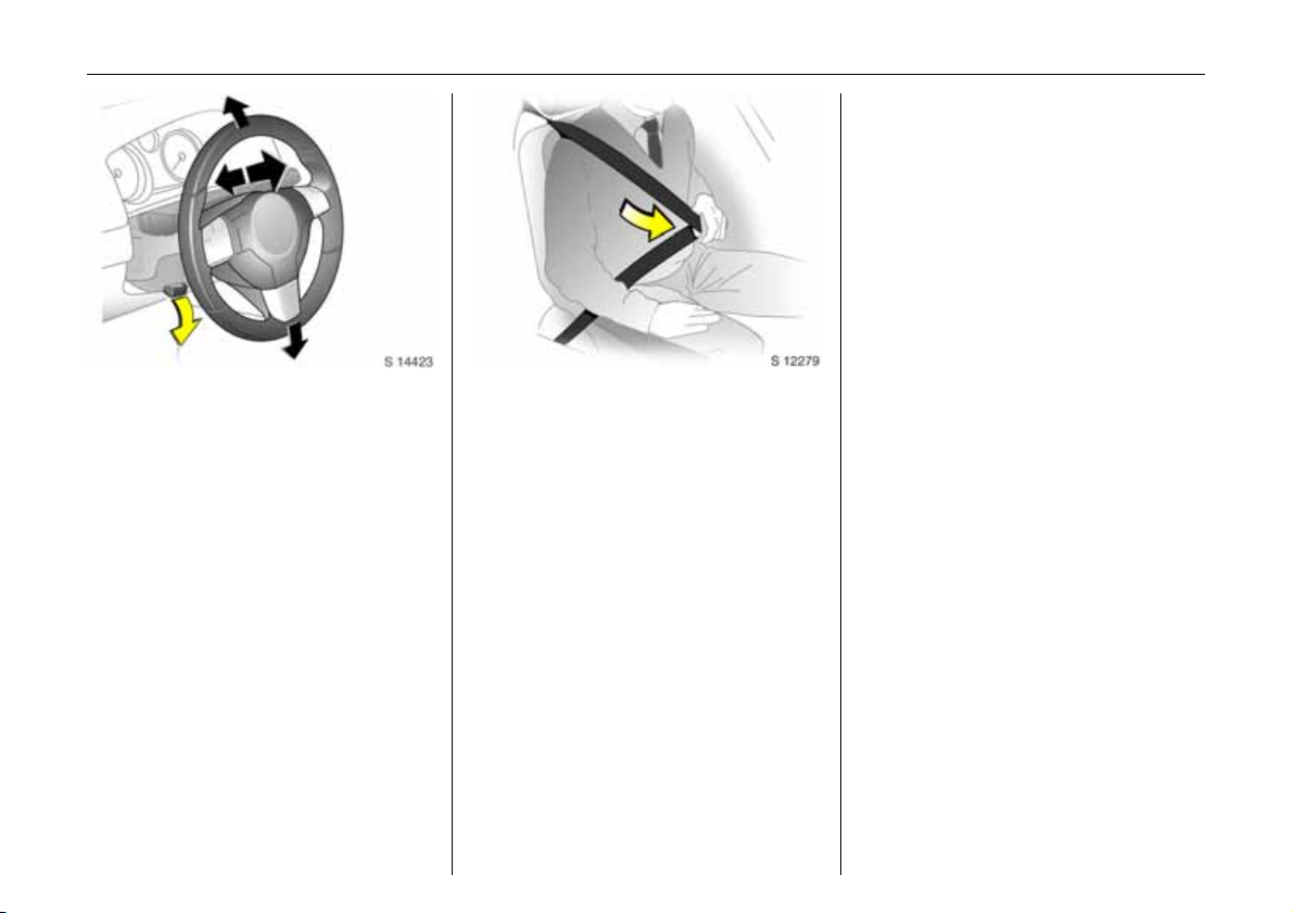
Picture no: s0013777.tif
Steering wheel adjustment:
Move lever down,
adjust height and distanc e,
move lever up and engage
Adjust s teerin g wh ee l on ly with ve hicle
stationary and steering column lock
released.
Push the leve r f irmly upwa rd s to e n sure
that the steering wheel is locked in position.
6 Airbag systems - see page 76.
Picture no: s11649.tif
Fitting seat belt:
Draw seat belt smoothly from
inertia reel, guide over shoulder
and engage in b uckle
The belt must not be twisted at any p oint.
The lap b elt must lie snugly against the
body.
The backrests must not be tilted back too
fa r (recommended maximum tilting ang le
approx. 25°).
To re lease belt, press red button on belt
buckle.
6 Seat be lts – see page s 72 to 74,
airbag systems – see page 76,
seat position – see page 56.
Page 10
6In brief
Page 11

In brief 7
Page
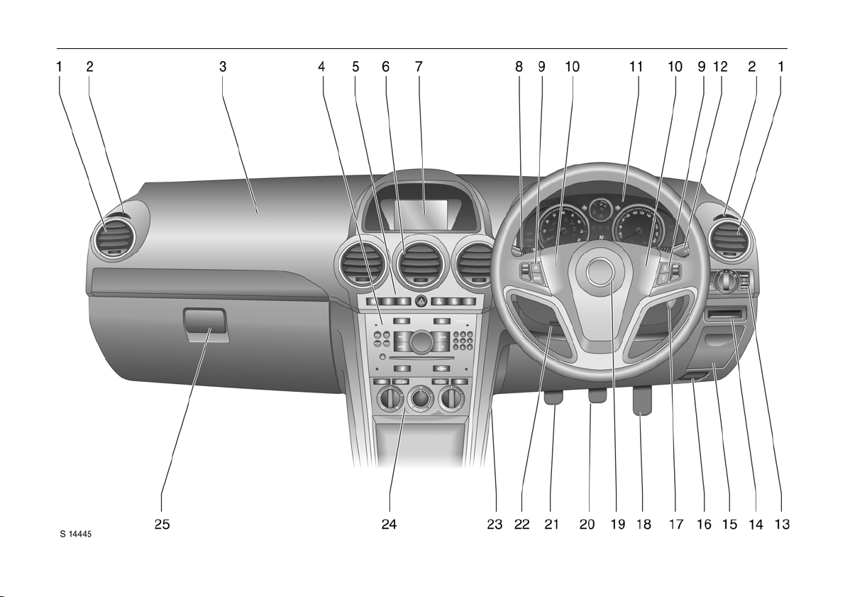
1 Side air v ents ......... .... ......... ......... ...... 98
2 Doo r win dow de froster v ents ..... .... ..9 8
3 Front pa ssenger’s airbag ..... ..... ......7 6
4 Radio 3, Infotainment system 3 ... ..4 4
5 Haza rd warning switc h . .... ......... ......1 4
Parking distance sensors 3 ........ .... 140
Desce nt Control Sys tem (DCS) ... .... 136
Electronic Stability Programm e
(ES P)) ........ ..... ......... ......... ........ ......... 134
Front pa ssenger’s
seat b elt re minder ..... ......... ......... ......73
Fold in ex terior mirrors .. .... ......... ...... 11
Security indicator for
Vauxhall alarm system 3 ...... ......... ..5 2
6 Centre air v ents ..... .... ......... ......... ...... 98
7 Central information display
Board Information Displa y 3 ..... .... ..3 2
Graphical Information Display 3 ... ..36
Colour Information Display 3 ........ .. 36
8 Stalk for
Windscreen and tailgate
wiper and wash ......... ......... ...14, 15, 16
Headlight wash 3 . .... ......... ......... ......1 5
Pa ge
9 Radio / Infotainment
remote control button s .... ..... .... ....... 4 5
Trip co m p u ter 3... ......... ......... ..... 34, 40
10 Horn ......... .... ......... ......... ......... ......... .. 1 4
11 Instruments .. ......... ......... ......... ......... .. 2 2
12 Stalk for
Headlight flash and m ain beam, ...12
Turn signal lights . ......... ......... ......... .. 13
Door-to-door lighting function . ..... .. 91
Cruise control 3 ... ......... ......... ......... 137
13 Light s witches for
Parking lights ............ .... .... ......... ..... .. 88
Dipped beam ....... ......... .... ..... ..... 1 2, 88
Automatic dipped beam
activation 3.......... ..... ........ ......... ....... 89
Headlight range adjustment 3 ....... 89
Front fog ligh ts..... ..... ........ ......... ....... 90
Fog tail lig ht ..... ......... ........ ......... ....... 9 0
Instrument illumination .... ......... ....... 91
14 Card holder .......... ..... ........ ......... ....... 6 9
15 Coin storage ..... ......... ........ ......... ....... 6 9
Page
16 Bonnet re lease leve r ............. ......... ... 55
17 Starter switch ...... ......... ......... ......... ... 1 2
18 Acce lerator pe dal ........ ......... ......... . 122
19 Drive r’s airbag ... ..... ............. ..... ....... 76
20 Brake pedal ......... ......... ......... ..122, 144
21 Clutch pedal 3 ......... ......... ...... 122, 124
22 Steering w he el a djustme nt lever ...... ..5
23 Fuse box ....... ........ ......... ......... ......... . 171
24 Climate c ontrol .. ......... ......... ......... ... 9 7
25 Glove compartme nt .... ......... .... 67, 106
Page 12

In b rie f8
Control indicators
ABS ( Anti-lock Brake System):
u
se e p ag e 146.
2
ESP OFF:
see page 134.
Drive r’s sea t belt rem inder:
X
see page 24.
Trailer in dic ator 3:
g
see page 22.
Brake system:
4
see pages 22, 144, 188.
Parking distance sensors 3:
r
see pages 23, 140.
Descent Control System (DCS):
5
see pages 23, 136.
All W heel Driv e (AWD ):
B
see pages 23, 115.
ESP Act ive & W arnin g
7
(Electronic S tability Prog ramm e):
see page 134.
ESP No t Ready :
A
see page 134.
Automatic headlight range
q
ad justme nt 3:
see page s 23, 23.
Cool ant temp era ture:
W
see pages 23, 186.
Electronic im mobil is er:
o
see page s 24, 47.
Door open:
9
see page 24.
Engine electronics,
3
tr a nsm is si on e le c tr oni cs 3:
see page s 24, 132.
Airbag systems 3,
v
belt tensione rs:
see page s 74, 76.
Tailgate open:
1
see page 24.
Turn sig nal lig hts:
O
see pages 13, 24.
Low fuel leve l:
Y
see pages 24, 128, 208.
Front fog lights:
>
see page 90.
Fog tail l ight:
r
see page 90.
Hea dlight main b ea m:
P
see pages 12, 24, 88.
Low windscreen wash fluid :
G
see page 25.
Water in diesel fuel filter 3:
6
see pages 25, 186.
Change engine oil 3 :
C
see pages 25, 185.
Page 13

In brief 9
Preheating for diesel engine 3:
N
see page 25.
Diese l par ticle filt er 3:
1111
see page 25.
Cruise control 3:
m
se e p ag e 137.
Engine oil l evel 3:
S
see pages 26, 183.
Power steering:
2
see page 26.
Oil p ressure :
I
see page 26.
Alternator:
p
see page 27.
Exhaust emissions:
Z
see pages 27, 130.
WINTER
Win t er p r ogram me :
(or n)
see pages 27, 111.
Ligh ting
Light switches,
switch positions:
see page s 12, 88.
JJJJ Lights off
Parking lig ht s
8
Dipp ed beam
9
Main beam
P
Front fog li ghts:
>
see page 90.
Fog tai l light:
r
see page 90.
AUTO Autom atic d ipped b eam
ac tivation 3:
see page s 12, 89.
Turn sig nal lig hts:
O
see pages 13, 24.
Instrume nt il luminati on:
k
see page 91.
d Front reading ligh ts,
cent re dome light s:
see page 92.
Haz ard w arning lig hts:
¨
see pages 14, 89.
Headlight range adjustment 3,
?
automa tic he adli ght range
adjustm ent 3:
see page 89.
Page 14

In b rie f10
Heatin g and v entilation Windscreen wiper
Fan rotary knob:
x
see page 99.
Air distri bution:
see page 99,
to head area,
M
to head area and footwell,
L
to footwell,
K
J
to windscreen and footwell,
l
to windscreen and head are a,
V
to w i nd scre en .
Hea ted rear window,
Ü
heated exte rior m irrors 3:
see pages 18, 107.
Air conditioning system:
n
se e p ag e 102.
4 Air recircula tion:
se e p ag e 101.
Automat ic air r ecirculation 3:
t
se e p ag e 104.
AUTO Automat ic mode 3 :
se e p ag e 105.
Heated front seats 3:
ß
se e p ag e 107.
Windscreen wiper
P
Windscreen wash,
n
headlight wash 3
Tail gate wiper
f
Wiper stalk positions:
see page 14.
O
Off
$
Intermittent wiping - or automatic wiping with ra in sensor 3
% Slow
& Fast
Automatic transmission 3
WI NT ER
Winter programme:
(o r n)
see page s 27, 111.
Autom atic mode :
D
see page 109.
Cruise control 3
Buttons on turn s ig na l stalk:
see page 137.
Store , decelerate,
9
Miscellaneous
Horn:
j
see page 14.
/ Bonnet:
see page 55.
p Ce ntral l ocking system :
loc king, see page 50.
Cen tral l ocking system :
q
unlocking, see page 50.
Cen tral l ocking switch:
m
see page 50.
Passenger’s seat belt reminder 3:
X
2
see page 73.
+ First-aid k it 3:
see page 166.
¨ Wa rning tri angle 3:
see page 166.
Cigaret te lighter:
)
see page 65.
Fold in exterior m irrors:
n
see page 11.
Child safety system for rear
z
window s:
see page 95.
Resume stored speed, accelerate,
8
Activate, deactivate.
:
Page 15
In brief 11
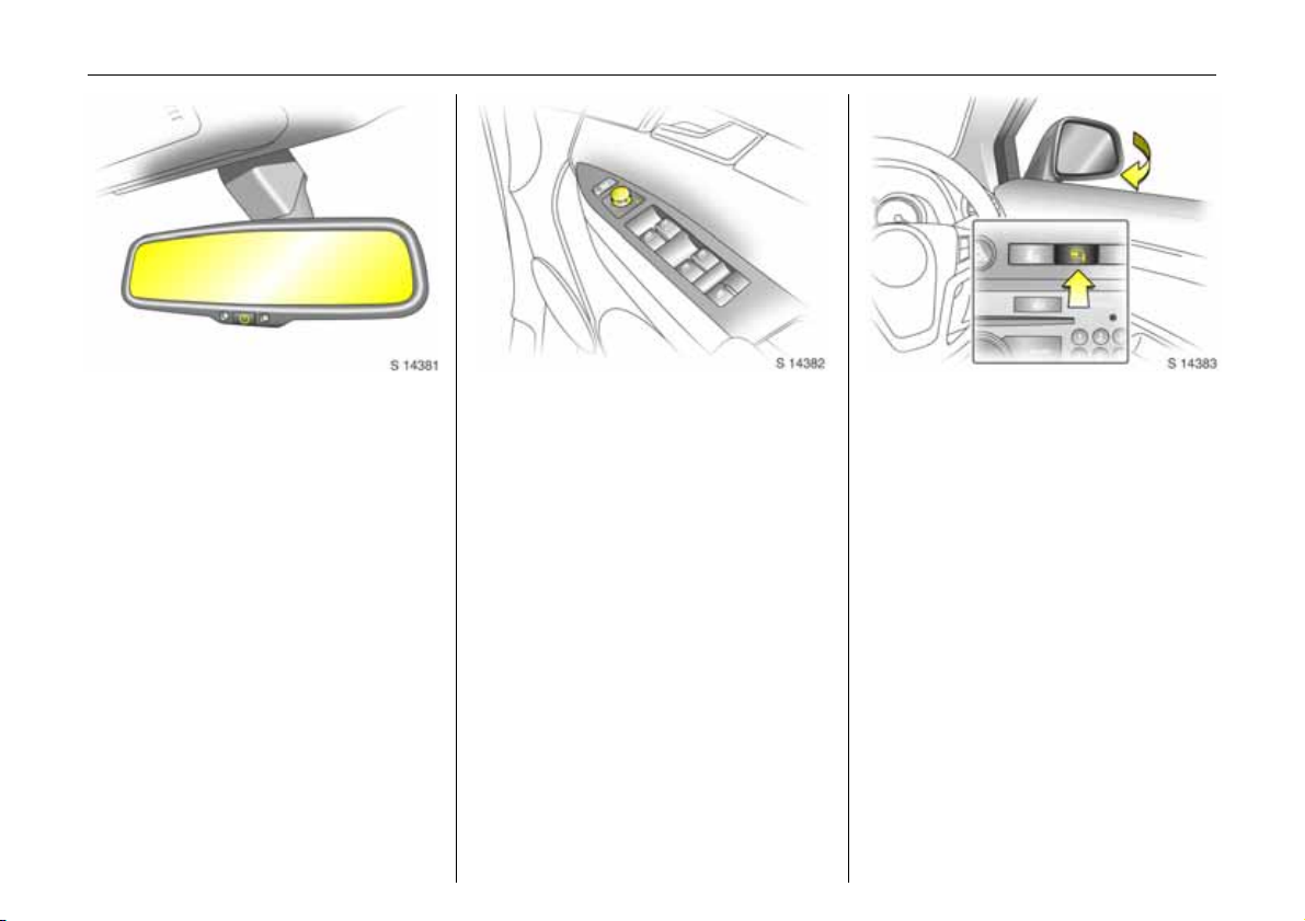
Picture no: s0013260.tif
To adjust interior mirror:
Swivel mirror housing
Swiv el lever 3 on underside of mirror
housing to reduce dazzle at night.
Take care when driving with interior mirror
adjusted for night vision. Rear view may be
slig htly distorted in this position.
6 Automatic anti-dazzle interior mirror 3 -
see page 86.
Picture no: s0013206.tif
Electrically adjustable exterior
mirrors 3:
Four way switc h on drive r’s doo r
Operational with sta rter switch in positions
ACC or ON .
With ke y in LOCK position in starter switch
or removed, the mirrors can be adjusted for
up to 10 minutes or until a door is opened.
Move selector switch to L or R: Four way
swi tch ad jus t s corre spondin g m irror .
6 Further information,
autom atic anti-dazzle exterior mirrors see page 86,
heated exterior mirrors - see page 107.
Picture no: s0013448.tif
Fold in exterior mirrors:
Manually: press lightly.
Electrically 3: with starter switch in
positions ACC or ON, press button n and
both mirrors will fold in.
Press button n again - both mirrors will
fold to the driving position.
With key in LOCK position in starter switch
or removed, the mirrors can be folded for
up to 10 minutes or until a door is opened.
If a fold ed-in e lectric mirror h as be en
folded out manually, pressing button n
only folds the other mirror out. Pressing
button n again folds both mirrors back in.
Never drive with mirrors in folded position.
Page 16
In b rie f12
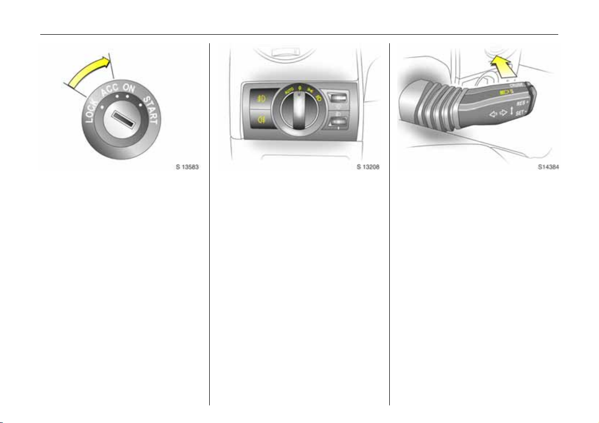
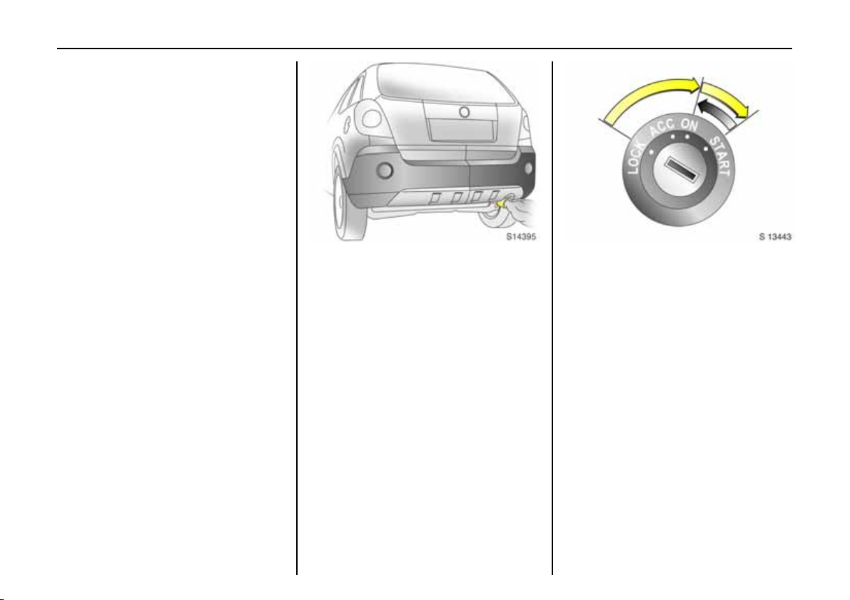
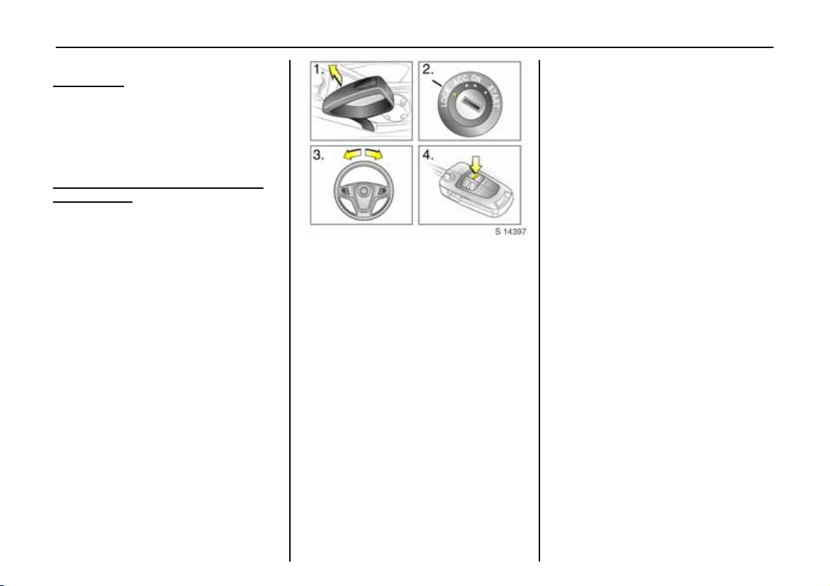
Picture no: s0013583.tif
Steering column lock and ignition:
Turn key to position ACC.
To release lock,
rotate steering wheel slightly
Positi on s:
LOCK =Ignition off
ACC = Steering unlocked, ignition off
ON = Ignition on, with diesel en gin e:
preheating
START = Start (transmission in neutra l)
Release key when engine starts and it will
automatically return to ON.
To lock the steering column, switch ignition
off, remove key and rotate steering wheel
until steering column lock is engaged.
6 Starting - see page 17,
electronic immobiliser - see pa ge 47,
parking the vehicle - see page 20.
Picture no: s0013208.tif
Ligh t s w itch:
JJJJ =Off
8
9 = Dipp ed bea m
AU T O
= Parking lights
= Automatic dipped
beam activation 3
Pu sh > = Front fog lights
Pre ss r = Fog tail light
6 Headlight warning device - see page 20,
further information - see page 88,
headlight range adjustment 3 see page 89,
headlights when driving abroad see page 93,
daytime running lights 3 - see page 88.
Picture no: s0013477.tif
Switching between dipped beam
and main be am:
Main beam = Push stalk
forward
Dipped beam = Pull stalk back
towards
stee r ing w hee l
Control indicator P is illuminate d when
main beam is on.
Page 17
In brief 13
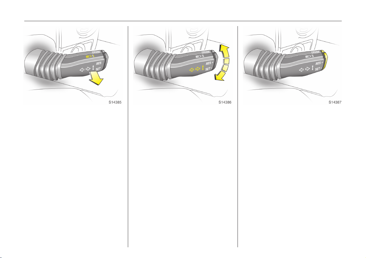
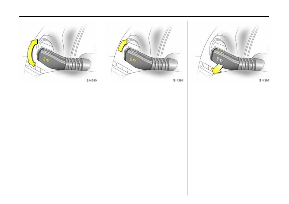
Picture no: s0013478.tif
Headlight flash:
Pull stalk towards steering wheel
When released, stalk will spring back to rest
position.
Picture no: s0013480.tif
Turn signal lights:
Stalk in rest position
Upwards = Right turn
Downwards = Left turn
When the steering wheel is turned back, the
stalk automatically returns to its rest
position. This will not happen when making
a minor steering manoeuvre such as lane
changing.
Tap signal: Briefly move stalk to resistance
point. The turn signal then flashes three
times when changing lanes or the like.
Hold the stalk if you want the turn signals
to flash for longer. When released, the stalk
will spring back to rest position.
The volume of the turn signal lights’
audible warning is dependent upon vehicle
speed.
Picture no: s0013683.tif
Cruise control operation 3:
Press button on stalk
Switch on: press button :.
Store current speed: press button
Switch off: press button
Resume at stored speed:
press button
6 Cruise control 3 - see page 137.
8.
:.
9.
Page 18
In b rie f14
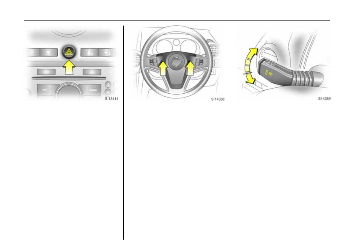
Picture no: s0013414.tif
Hazard warning lights:
On = Press ¨
Off = Press ¨ a gai n
Operational with ignition on or off.
Wh en the hazard warnin g lights are on , t he
control indicator in the button flashes in
unison with the turn signal lights.
Picture no: s0013249.tif
Horn j:
Press either side of the steering wheel to
activate the horn.
The horn will sound regardless of starter
swi tch positio n.
Picture no: s0013251.tif
Windscreen wiper:
Move stalk upwards
O =Off
$ = Timed interval wipe
% =Slow
& =Fast
Press stalk down from position O:
Single swipe.
6 Further information - see pages 189, 195.
Page 19
In brief 15
Picture no: s0013479.tif
Windscreen wiper:
Adjustable wiper interval 3
To set the wiping interval to a value
between 1 and 10 seconds:
Switch on ignition.
Push stalk down from position O.
Wait until wiping frequency reaches the
desired interval.
Set the stalk to adjustable timed interval
wiper position $.
The interval remains stored until the next
change or the ignition is switched off.
Switching the ignition on and m oving the
stalk to $ sets the interval to 3.5 seconds.
In this mode, wiping frequency is also
affected by vehicle speed. As vehicle speed
increases, wiping will become more
frequent.
Picture no: s0013481.tif
Automatic wiping with rain
sensor 3 :
The rain sensor detects the amount of
water on the win dscreen and a utomatica lly
regulates the windscreen wiper.
Move stalk to autom atic wiping with rain
sensor position $
The wiper operates for one cycle to check
the system when the starter switch is turned
to ACC.
To turn wiper off, move stalk to position O.
6 Further information - see pages 190, 195.
$.
$$
Picture no: s0013482.tif
Operating windscreen and
headlight wash systems 3:
Pull stalk towards steerin g wheel
Wash fluid is sprayed onto the windscreen.
The wiper operates for two cycles after the
stalk has been released and once more
after a 3 second delay.
The headlight wash system 3 can only be
operated when the headlights are on.
Wash fluid is sprayed onto the headlights.
The headlight wash system will not operate
for 1 minute after initial spraying. If wash
fluid level is low then this delay is increased
to 2 minutes.
6 Further inform ation - see page 190.
Page 20
In b rie f16
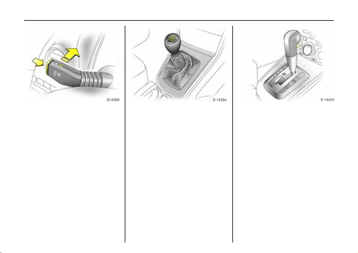
Picture no: s0013483.tif
Tailgate wash and wipe system:
Wiper on = Push stalk forward
Wiper off = Pull back towards
steering wheel
Wash = Press and hold
button
Wash fluid is sprayed on to tailgate
window when the button on the end of the
stalk is pressed. When the button is
released, washing will stop, but the wiper
will continue to swipe for a pprox. 3 cycles.
Tailgate wiper operates automatically
when w indscreen wiper is operating and
rev erse g ear h as be en s ele cted 3.
6 Further information - see page 190.
Picture no: s0013612.tif
Manual transmission:
1 to 5 = 1st to 5th gear
R = Reverse gear
Only en gag e reverse g ear when the veh icle
is stationary.
Picture no: s0013252.tif
Automatic transmission 3:
P=Park position
R=Reverse
N=Neutral (idle)
D = Automatic gear selection
Manual mode:
= Shift to higher gear
+
=Shift to lower gear
-
Starting is only possible in P or N. To move
from P or N, switch on ignition, depress
footbrake and press selector lever button.
Engage P or R: press selector lever button.
P: Only with vehicle stationary, first apply
handbrake
R: Only with vehicle stationary.
6 Automatic transmission - see page 10 9.
Page 21
Before starting-off check:
z Tyre pressures and condition.
z Underneath the vehicle for any leaks.
z Engine oil level and fluid levels in engine
com partment (see page 183).
z All windows, mirrors, exterior lighting
and num ber p la tes are fre e fro m dirt,
snow and ice and are operational.
z Objects are se curely located and will not
be thrown forwards in the event of
sudden braking.
z Seats, seat belts and mirrors are
correctly ad justed.
z All gauges and control indicators.
z Brake op eration.
Picture no: s0013254.tif
Exhaust gases are poisonous
Exhaust gases contain carbon monoxide,
wh ic h is extrem ely poisonou s b ut has no
od our or c o lo u r.
The refore never inhale exhaust gases a nd
never run the engine in an enclosed space.
You should also avoid driving with the
doors open, as exhaust gases could enter
the passenger compartment.
6 Exhaust gases - see page 132.
In brief 17
Picture no: s0013443.tif
Starting the engine:
Man ual tra nsmi s sion in neutral ,
Depress clutch and footbrake,
Automatic transmission in P or N,
Do not accelerate
Petrol engines:
Turn key to START and release it
Di es el eng i n es :
Turn key to ON,
when preheating control
indicator N
N go es out
NN
1)
,
turn key to START and release it
Key returns automatically to ON position
when released.
1)
Preheating system switches on only if outside
tem perature is low.
6
Page 22
In b rie f18
Start attempts should not last longer than
15 se cond s. If engi n e does n o t s ta rt, wait
10 seconds before repeating starting
procedure.
Th e increa sed en gin e s pe ed au tomatically
returns to normal idling speed as the
engine temperature rises.
Drive at a moderate speed, especially in
cold weather, until normal e ngine
operating temperatures have been
reached.
6 Elec tronic imm obiliser - see page 47,
further information see page s 123, 125, 127.
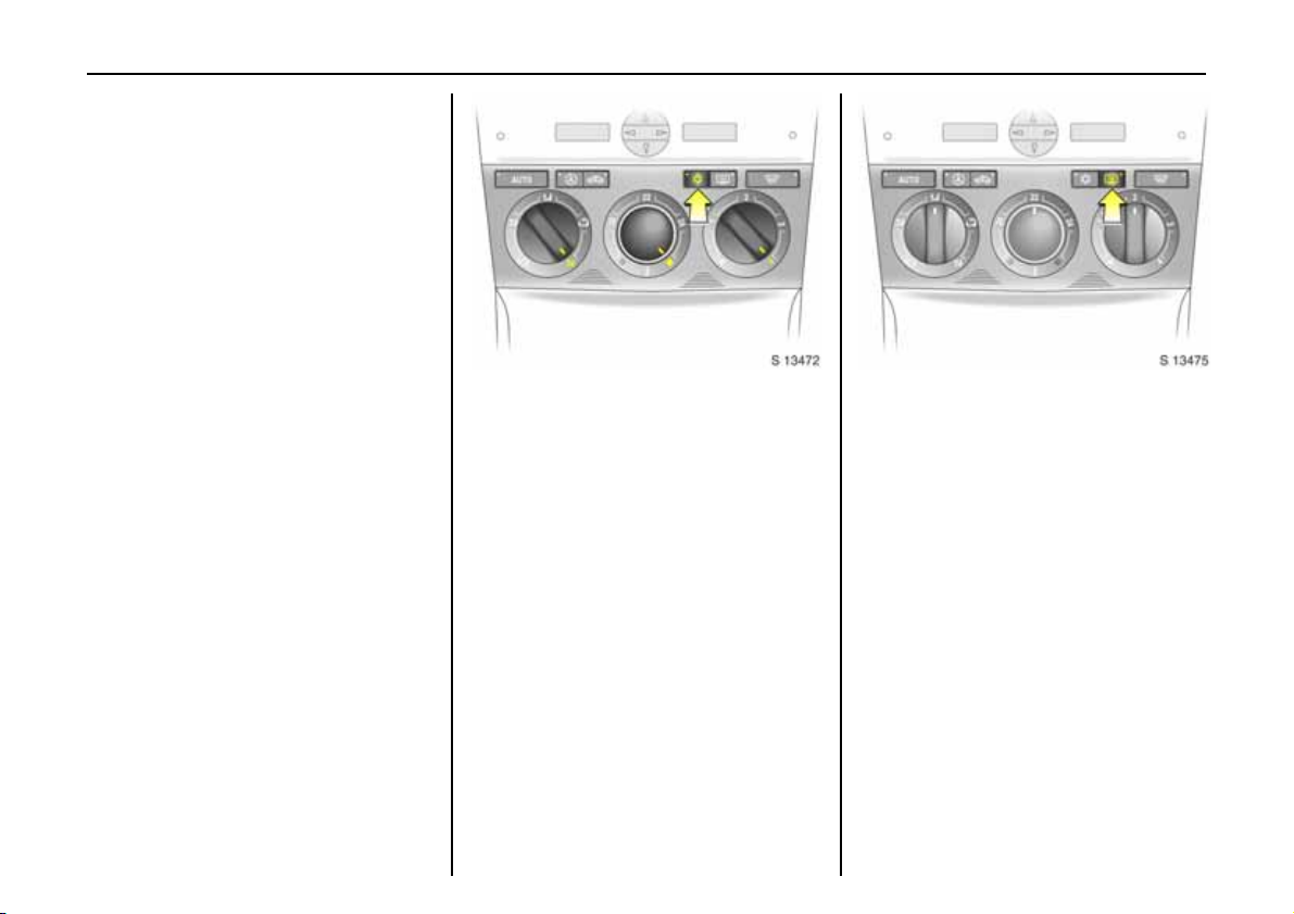
Picture no: s0013472.tif
Drying misted up or iced up
wind ow s:
Set the temperature rotary knob
to red and fan to position 4,
set air distribution to l
Close centre air vents; open side air vents
and direct them towards the door windows.
6 Heating, ventilation and air conditioning
system - see pages 99, 102.
Picture no: s0013475.tif
Heated rear window,
heated exterior mirrors 3
Press Ü =On
Press Ü a gain = Off
Heating operational only in starter switch
positions ACC or ON.
The rear window a nd exterior mirror
heating is switched off automatically after
approx . 15 minutes.
6 Further information - see page 107.
Page 23
In brief 19
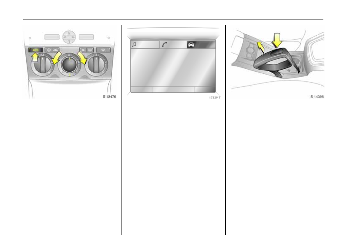
Picture no: s0013476.tif
To set automatic mode of
Electronic Climate Control
(ECC) 3:
Press AUTO button,
set temperature using rotary
kn ob
Open all a ir vents.
6 Elec tronic Climate Control (ECC) -
see page 104.
Ra n g e
Inst. consumpt.
19,5° 19:36
257
34.6
miles
mpg
Picture no: 17329T.tif
In for ma tio n d is pl ay 3:
Provides the following informat ion:
- time,
- outside temperature,
- radio 3 and date,
- navigation 3,
- telephone 3 ,
- check control 3,
- trip comp uter 3.
6 Information display 3 - see page 29.
Picture no: s0012815.tif
Releasing the handbrake:
Raise lever slightly,
press lock button,
lower lever fully,
handbrake release is audibly
confirmed
To re duce operating forces, depress
footbrake at the same time.
Do not drive with handbrake on, to avoid
damage to brakes on the rear w heels. Do
not apply handbrake while vehicle is in
motion or as a substitute for the footbrake.
6 Handbrake - see page 145.
Page 24
In b rie f20
Warning buzzers
Whilst driving:
z while operating the turn signals.
z if d riv er ’ s o r pa ss en ge r’ s se at b e lt 3
is not engaged when the seat is occupied
and vehicle speed e xceeds approx .
14 mph (22 km/h).
When th e vehicle is parked and driver’s
door is opened:
z with exterior lights switched on.
z when the key is in the sta rter switch.
6 Seat belt warning chimes -
see page s 24, 73,
driving hints - see page 122,
save fuel, protect the environment see page 125.
Picture no: s0013599.tif
Parking the vehicle:
Apply handbrake firmly,
close windows,
switch off en gi ne ,
remove key,
engage steering column lock,
loc k ve hi cle
6 Further information - see pages 47, 123,
remote control - see page 48,
central locking system - see page 50,
Vauxhall alarm system - see page 52.
When parking:
z Always apply handbrake firmly. Engage
first gear on uphill gradients or reverse
gear on d ownhill gradients. On slopes
apply the handbrake as firmly as
possible.
z Turn whe els away from the road when
parking on downhill gradients or
towards the road when parking on uphill
gradients.
z Push key into starter switch before
removing (v ehicles with automatic
transmission 3 : apply footbrake and
shift into P before removing key). Turn
steering wheel until lock is felt to engage
(anti-theft protection).
z Switch off exterior lights, othe rwise the
headlight warning de vice will sound
wh en the driver’s do o r is ope ne d.
z Cooling fans may run on after the engine
ha s bee n switch ed o ff.
z Do not park vehicle on easily ignitable
surfaces as the hot exhaust system
tempe ratures could cause the surfa ce to
ignite.
Page 25
In brief 21
Service work, Maintenance
We recommend that you entrust all w ork to
your Vauxhall Authorised Repairer, who
can provide you with reliable service and
correctly perform all work according to
factory instructions.
6 If you have a problem - see pag e 180,
engine oil life monitor - see pages 25, 185.
Genuine Vauxhall Parts and
Accessories
We recommend the use of “Genuine
Vauxhall Parts and Accessories” and
conversion parts released e xpressly for
your vehicle type. These parts have
undergone special tests to establish their
reliability, safety and specific suitability for
your vehicle. Despite continuous market
monit oring, we ca nno t a ss es s or gu arante e
these attributes for other products, even if
they have been granted approval by the
relevant authorities or in some other form.
“Genuine Vauxhall Parts and Accessories”
and conversion parts approved by
Vauxhall can be obtained from your
Vauxhall Authorised Repairer, who can
provide comprehensive ad vice about
permitted technical changes and e nsure
that the part is installed correctly.
9 Warning
Carry out regularly the checks
recom mended in this Owne r's Manual.
Ensure that yo ur vehicle is se rv iced at the
service intervals spec ified in the Serv ice
Booklet.
Have faults remedied without delay.
Consult a workshop. If necessary,
interrupt your journey.
6 Maintenance - see pages 182 to 192.
That was the most important
information for your first drive in
your v ehicle.
Your vehicle has still more
instruments and controls,
possibly also optional equipment.
The re ma in ing ch apt er s of the
Owner’s Manual contain
important information on
operatio n, safety and
maintena nce as well as a
com plete index.
Page 26
22 Instruments
Instruments
Control in dicators .... ..... ......... ........ ..... 22
Fuel gau ge .. ......... ......... ......... ........ ..... 27
Tran sm iss i on disp lay 3 ............. .... ..... 28
Tachometer..... ..... ......... ......... ........ ..... 28
Spe ed om eter... ......... ......... ......... ......... 28
Odometer / trip odometer ........ ......... 29
Information display ...... ......... .... .... ..... 29
Outside tempe rature.... .... ......... .... ..... 30
Stop w atch .. .... ......... ......... ......... ......... 43
Display of current tyre pressure 3 .... 44
Che ck con trol 3 ... ......... ......... ........ ..... 44
Radio reception 3 ......... ......... ........ ..... 44
Steering wheel mounted remote
control 3 ....... ..... ......... ......... ........ .....
Infotainment and navig ation
sy ste ms 3.. .... ......... ......... ......... .... .....
Mobile telephones and radio
equipment (CB) 3 ...... ......... ........ ..... 45
45
45
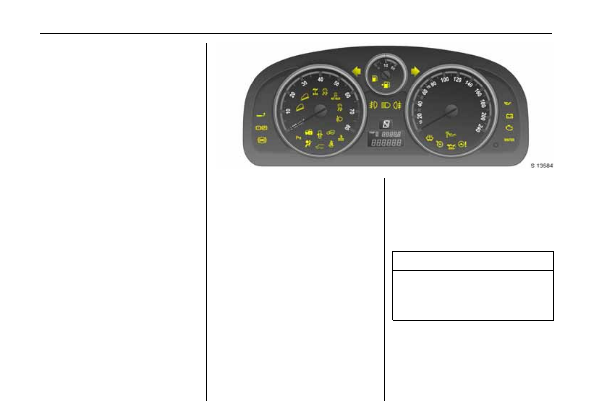
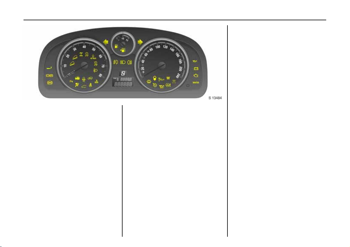
Picture no: s0013584.tif
Control indicators
The control indica tors described here are
not present in all vehicles. The descriptions
howe ver, apply to all instrument versions.
The colours of the control indicators mean:
z Re d Dange r, important reminder
z Y ellow Warning, informa tion, fault
z Green Switc h-on confirmation,
z Blue Switc h-on confirmation.
u
Anti-lock Brake System (ABS)
see page 146.
g
Trailer in dic ator 3
Illum inates when a traile r is connected to
the vehicle. Extinguishes when the trailer is
disconnected.
4
Picture no:
Brake system
Illuminates when ignition is switched on.
Goes out afte r engine is started.
Illuminates when engine is running if
handbrake is applied and/or fluid level for
brake hydra ulics is too low.
9 Wa rnin g
If it illuminates when the handbrak e is not
applied: stop vehicle; interrupt y our
journey immediately and consult a
workshop.
Further information - see pages 144, 188.
Page 27
Instruments 23
r
Parking distance sensors 3
Illuminates for approx. 4 seconds when
ignition is switched on.
If it stays illuminated when the ignition is
on, there is a fault in the system -
see page 140.
5
Descent Control System (DCS)
Both control indicators illuminate for
approx. 4 seconds when ignition is
switched on.
Green: illuminates when DCS is ready for
operation.
Flashes during driv ing when DCS is in
operation, after pressing DCS button.
Amber: illuminates to indicate there is a
fault in the system.
Flashes to indicate system is not ready for
conditions to operate.
Further information - see page 136.
B
All W heel Dri ve (AWD )
Illum inates for approx. 4 seconds whe n
ignition is switched on.
If it flashes during driving, the AWD system
is temporarily disabled.
If it illuminates, there is a fault in the
system. Consult a workshop as soon as
possible.
Further information - see page 115.
7
ESP Act ive & W arnin g
(Electronic S tability Prog ramm e)
see page 134.
A
ESP N ot R e ady
see page 134.
2
ESP O FF
see page 134.
q
Autom atic head ligh t ra nge
ad justment 3
Illuminates for approx. 4 seconds when
ignition is switched on.
Illuminates during driving to indicate a
fault that requires immedia te attention.
Consult a workshop as soon as possible.
Furthe r information - see page 23.
W
C oolant temp era ture
Illuminates for approx. 4 seconds when
ignition is switched on.
If it illuminates when the eng ine is running:
Stop vehicle and switch off engine. Coolant
temperature too high: Danger of engine
damage. Che ck coolant level.
9 Wa rnin g
Allow engine to cool down before
removing coolant filler cap.
Furthe r information - see page 186.
Page 28

In st rum ent s24
o
Electronic im mobil iser
Illuminates for approx. 4 seconds when
ignition is switched on.
If it illuminates when the ignition is on,
there is a fault in the immobiliser system;
the engine cannot be started see page 47.
9
Door open
Illuminates when a door is open.
3
Engine electronics,
transmission electronics 3
Illuminates for approx. 4 seconds when
ignition is switched on.
If it illuminates during driving:
There may be a fault in the engine or
transmission electronics; interrupt your
journey and consult a workshop as soon as
possible.
Further information - see page 132.
v
Airbag systems 3,
belt tensio ne rs
see page s 74, 76.
1
Ta ilgat e op en
Illum inates when ignition is switched on.
Illum inates when tailgate is open or not
securely latc hed.
X
Drive r’s sea t belt remi nder
Illum inates for approx. 4 seconds whe n
ignition is switched on.
When the engine is running, if d river’s seat
belt is not engaged, it will flash for approx.
90 seconds and then illuminate until
driver’s seat belt is fastened.
If vehicle speed exceeds approx. 14 mph
(22 km/h), control indicator will flash for
approx. 90 seconds along with a w arning
chim e and then remains illuminated until
driver’s seat belt is fastened.
Seat belts - see page 72.
OOOO
Turn sig nal lig hts
The re leva nt control indicator f lashes wh en
the turn signal is on. Rapid flash: failure of
a turn signal bulb or the corresponding
fuse or failure of a trailer turn signal bulb 3.
Both control indicators flash when the
ha zard warning lights are active.
Bulb replacement - see page 174,
fuses - see page 170.
YYYY
Low fuel level
Illuminates for approx. 4 seconds when
ignition is switched on.
If it illumina tes during drivin g: f uel level lo w,
fill up fuel tank as soon as possible.
Never let the tank run dry.
Erratic fuel supply can cause catalytic
converter to overheat - see page 130.
Diesel eng ine s: If the tank has been run dry,
bleed the fuel system as described on
page 160.
>
Front fog li ghts
Illuminates when front fog lights are
switched on - see page 90.
r
Fog tai l light
Illuminates when the fog tail light is
switched on - see page 90.
P
Headlight m ain be am
Illuminates when main be am is on and
when headlight flash is operated -
see page 12.
Page 29
G
Picture no: s0013484.tif
Low wi ndsc reen wa sh fl uid
Illuminates for approx. 4 seconds when
ignition is switched on.
If it illuminates: windscreen wash fluid level
low, add wash fluid as soon as possible -
see page 190.
6
Water in diesel fuel filter 3
Illuminates when water level in diesel fuel
filter exceeds a specified level. Residual
wate r in the diesel f u el filter will nee d to be
drained - see page 186. Consult a
workshop as soon as possible.
C
Picture no:
Change engine oil 3
Illum inates for approx. 4 seconds whe n
ignition is switched on.
Illuminates to indicate that engine oil
needs changing im mediately. Within
approx. 600 miles (1000 km), engine power
may be d ecreased.
Once the engine oil has been changed, the
sy st e m nee ds to be res et - se e p age 18 5.
Instruments 25
N
Preheating for diesel engine 3
Illuminated during preheating.
Preheating system switches on only if
outside temperature is low.
If it illuminate during driving, or the engine
cannot be started, consult a workshop as
soon as possible.
Starting the engine - see page 17.
1111
Die sel parti cle filte r 3
Illuminat es when dies el particle filter
requires cleaning.
As soon as the road and traffic situation
permits it, increase speed to more than
30 mph (50 km/h) for approx . 15 minutes.
The control indicator goes off as soon as
cleaning is complete.
Page 30
In st rum ent s26
m
m
m m
Cruise control 3
see page 137.
S
Engine oi l level 3
Illuminates for approx. 4 seconds when
ignition is switched on.
If it illuminates during driving: oil level low,
top up oil to specified level - see pa ge 183.
2
Powe r ste ering
Illuminates for approx. 4 seconds when
ignition is switched on.
If it does not illuminate when the ignition is
switched on, stays illuminated or
illuminates during driving, there is a fault in
the system. Consult a workshop as soon as
possible.
I
Oil p ressure
Illum inates when ignition is switched on.
Goes out after engine is started.
Can illuminate intermittently when idling
with hot engine; must go out when engine
speed is increased.
If illum inated during driving:
Engine oil pressure may be dangerously
low , interrupting engine lubrica tion and
resulting in da mage to the engine and/or
locking of the driving w heels:
z Move out of the flow of traffic as quickly
as possible without impeding other
vehicles.
z Depress clutch,
z Move gearshift lever to neutral
(automatic transmission to N),
z Switch off ignition.
9 Wa rnin g
When the engine is off, considerably
greater force will be required for b raking
and steering.
Do not remove key until vehicle has come
to a standstill, otherwise the steering
column lock could engage unexpectedly.
C heck o i l le ve l bef or e cons u lting a
workshop. If the oil le vel is low, top up using
the specified engine oil - see page 183.
If the oil level is normal, have a workshop
check the vehicle’s lubricating system.
Page 31

Instruments 27
p
Alternator
Illuminates when ignition is switched on.
Goes out after engine is started.
If illuminated during driving:
Stop vehicle and switch off engine. The
battery is not being charged and the
engine cooling may be interrupted. The
brake servo unit may cease to be effective.
Interrupt your journey immediately.
Remove key and check drive belt c ondition
and tensioning before consulting a
workshop.
ZZZZ
Exhaust emissions
Illum inates when ignition is switched on.
Goes out after engine is started. Can
illuminate briefly when driving; this is
normal and does not indicate a system
fa ul t .
If it illuminates when the engine is running:
Fault in emission control system . The
permitted emission limits may be
exc eeded. Fue l economy and ve hicle
driveability may be impaired.
The control indicator also illuminates if
there is a fa ult in the diesel particle filter 3.
Consult a workshop as soon as possible.
If it flashes when the engine is running:
For a fault that ca n lead to destruction of
the catalytic conv erter, see page 130.
Consult a workshop as soon as possible.
WIN TER (or n)
Wi nt er pr o gr am m e 3
Control indica tor illuminates in instrument
cluster when Winter programme for the
automatic transmission is enabled see page 111.
Picture no: s0013485.tif
Fuel gauge
Indicates fuel level when the ignition is on.
After adding fuel and restarting engine,
fu el g auge p ointer slo wly moves to s how
new fuel level.
Movement of fuel in tank when cornering,
braking or accelerating may cause the
pointer to m ove temporarily.
When fuel gauge indicates that fuel sup ply
is low, control indicator Y illuminates:
Fill up fuel tank as soon as possible -
see page 127.
Never let the fuel tank become empty.
Page 32

In st rum ent s28
Picture no: s0013486.tif
Transmission display 3
Display of the se lecte d gear or mode with
automatic transmission 3.
P Park po si tion .
R Reverse gear.
N Neutral.
D Automatic mode.
1 to 5 Selected gear in Manual mode.
Picture no: s0013487.tif
Tachom eter
Making u s e of th e tachom eter helps to
sav e fuel; it indicates the engin e spe ed in
revolutions per minute (rpm).
Red warning zone on right: maximum
permissible engine speed exceeded,
danger to engine.
If possible, drive in each gear in the low
engine speed range (between approx.
2000 and 3000 rpm) and maintain an even
vehicle speed to maximise fuel efficiency.
Picture no: s0013488.tif
Speedometer
Indicates the vehicle speed.
Page 33

11:25} 21.5°C
11:25} 21.5°C
Range
Range
RDS [ TP]
RDS [ TP]
257km
257miles
Instruments 29
Ra n g e
Inst. consumpt.
19,5° 19:36
257
34.6
miles
mpg
Picture no: s0013497.tif
Odometer / trip odometer
Odometer:
Th e odomete r indicates how fa r th e ve hicle
has been driven.
Trip od ometer:
Th ere are two indep endent trip odome ters
which indicate how far the vehicle has been
driven since the last reset.
Press the trip odometer button once to
toggle between "Trip A" and "Trip B".
To rese t a trip odometer, press and hold
the trip odometer button.
Picture no: 17337T.tif
In for ma tio n d is pl ay
Board Inform ation Displ ay 3
Display of time, outside temperature a nd
date / Infotainment system (when it is on).
An F in the display indicates a fault.
Have th e cau s e of the fa ult remed ied by a
workshop.
Grap hical I nformat ion Display 3,
Picture no: 17329T.tif
C olour Informa tion Display 3
Display of time, outside temperature, and
date / Infota inment system (when it is on).
The Graphical Information Display
presents the information in monochrome.
The Colour Information Display presents
the information in colour.
Page 34

In st rum ent s30
The type of information and how it is
displayed depends on the equipment of
th e v ehicle and the settin gs o f the trip
computer 3 and Infotainment system 3.
Some information appears in the display
in an abb reviated form.
Infotainment system –
see Infotainment system instruction
manual.
An F in the display indicates a fault.
Have the cause of the fault remedied by a
workshop.
:
11:25} -1.5°C
Range
RDS [ TP]
257miles
Picture no: 17337T.tif
Outside temperature
A fall in temperature is indicated
immediately and a rise in temperature
after a tim e delay.
If outside temperature drops to 3 °C,
the symbol : illuminates in the Board
Information Display 3 as a warning for
icy road surfaces. : remains illuminated
until temperatures reach at least 5 °C.
Slippery road
-2,5°C
OK
Picture no: 17338T.tif
In vehicles with Graphical I nformation
Display 3 or Colour Information Display 3,
a warning message appears in the display
as a warning for icy road surfaces. There is
no me ssage below -5 °C.
9 Wa rnin g
Caution: The road surface may already
be icy even though the display indicates
a few degrees ab ove 0 °C.
Page 35

11:25} 21.5°C
Range
257miles
Instruments 31
Picture no: 17337T.tif
Board Information Display 3,
selecting functions
Functions and settings of some equipment
can be accessed via the Board Information
Display.
This is done via the menus and the buttons
on the Infotainment system 3 or with the
left adjuster wheel on the steering wheel.
The relevant menu options are then shown
on the subsequent row of the display.
Select menu items using the arrow buttons:
Picture no: s0013209.tif
OK button Select highlighted item,
confirm command
To exit a menu, press the right or left a rrow
button to rea ch Return or Main and select.
To select using the multi-function knob:
Picture no: 17013T.tif
Turn Highlight menu items or
commands, select functions.
Press Select h ighlighted item , confirm
command.
To exit a menu, turn the multi-function
knob left or right to Return or Main and
select.
If c heck control 3 issues a warning
message, the display is blocked from other
functions. Acknowledge the message by
pressing the multi-function knob. If there
are several warning messages,
acknowledge them one at a time.
Page 36

In st rum ent s32
The functions are displayed in the following
order:
z Time synchronisation
z Time, setting hours
11:25} 21.5°C
System
z Time, setting minutes
z Date, setting day
z Date, setting month
z Date, setting year
z Ignition logic
z Language selection
z Setting units of measure
To select using the left adjuster wheel on
Picture no: s0013511.tif
th e s tee rin g whee l:
Turn up Previous menu item
Turn down Next menu item
Press Select highlighted item,
confirm comma nd
If check control 3 issues a warning
message, the display is blocked from other
functions. Acknowledge the message by
pre ssing the le ft adjuster wheel. I f th ere are
several warning me ssages, acknowledge
them one at a time.
Picture no: 17337T.tif
Board Information Display 3,
system s ettings
Pre ss the Settings button of the
In fotain m e nt sy ste m. Me n u item Audio or
System will appear.
Press the left arrow button to reach menu
item System and select. The first function
of the System menu is highlighted.
Some of the functions appear on the
display in an abbreviated form.
Page 37

11:25} 21.5°C
Clock Sync.On
Picture no: 17337T.tif
Corr ect ing tim e
Some RDS transmitters do not send a
correct time signal. If the incorrect time is
continually displayed, deactivate
automatic time synchronisation 3 and set
the time manually – see next column.
The automatic setting is indicated by } in
the display.
To correct time with the help of RD S, select
the menu item for time synchronisation
fro m t he Sett ings me nu.
Make the desired setting.
Settin g d ate and time
Select the menu item for time and date
setting from the Sett ings me nu.
Make the desired setting.
The setting is saved when the menu item is
exite d.
Igniti on logic 3
See Infotainment system instruction
manual.
Instruments 33
11:25} 21.5 °C
English
Picture no: 17337T.tif
Language selection
You can select the display language for
some functions.
Select the menu item for language from the
Sett ings me nu and make the desired
setting.
Page 38

In st rum ent s34
11:25} 21.5°C
Unit Europe-SI
Picture no: 17337T.tif
Setti ng units of measure
You can select which units of measure are
to be used.
Select the menu item for units of measure
from the Settings menu and mak e the
desired setting.
Board Information Display 3,
trip computer 3
The trip computer provides information on
driving data, which is continually recorded
and evalua ted electronically.
Ac cess trip computer vehicle data by
pressing the BC button on the Infotainment
sy st e m or the le f t adju ste r whee l on th e
steering wheel.
Some of the functions appear on the
display in an abbreviated form.
Once a funct ion h as be en selected , the
subsequ ent rows o f the tr ip computer
function are displayed.
The functions are displayed in the following
orde r:
z Instantaneous consumption
z Average consumption
z Effective consumption
z Average speed
z Distance travelled
z Range
z Stop watch
11:25} 21.5 °C
Inst. Consumpt.
34.6mpg
Picture no: 17337T.tif
Instantaneous consumption
Display c hanges depending on speed:
Display in g al/h below 8 mph (13 km/h).
Display in mpg above 8 mph (13 km/h).
Page 39

Average c onsum ption
Display of average consumption.
The m easurement can be restarted at any
time – see next page.
Effective consumpt ion
Displays amount of fuel consumed.
The m easurement can be restarted at any
time – see next page .
Ave r ag e sp eed
Display of average speed.
The m easurement can be restarted at any
time - see next page.
Stoppages in the journey with the ignition
off are not included in the calculations.
Dis tance tra velled
Displays number of miles / kilometres
driven. The measurement can be restarted
at any time – see next page.
11:25} 21.5°C
Range
257miles
Picture no: 17337T.tif
Range
Range is calculated from current fuel tank
content and instantaneous consumption.
The display shows average values.
The vehicle updates the range
automatically after a brief delay w hen the
vehicle has been refuelled.
If the fuel in the tank will allow less than
30 miles (50 km) of travel, the warning
"Refuel" appears on the display.
Instruments 35
11:25} 21.5 °C
Stop Watch
01:22:32h
Picture no: 17337T.tif
St op wa tch
Operating using the arrow b uttons:
To start, press left arrow button to select
menu item Start and press OK button to
start / stop.
To reset, press left a rrow button to select
menu item Reset and press OK button.
Operating using the left adjuster wheel on
the steering wheel:
To start, select menu item Start and press
to start / stop.
To reset, select menu item Reset and press
to confirm command.
Page 40

In st rum ent s36
Reset ting tri p co mp uter informat ion
The following trip computer information
can be reset ( restart o f mea surem ent /
calculation):
z Average consumption
z Effective consumption
z Av erage s pee d
z Distance tra velled
Select the desired trip computer
information or select menu item All v alu es.
Reset by p ressing the lef t adjuster wheel on
the steering w heel or the OK button on the
Infotainment system.
Interruption of power suppl y
If the power supply has been interrupted or
if the battery voltage has dropped too low ,
the values stored in the trip computer will
be lost.
Ra n g e
Inst. consumpt.
19,5° 19:36
257
34.6
miles
mpg
Picture no: 17329T.tif
Graphical Information Display 3
or Colour Information Display 3,
selecting functions
The functions and settings of some
equipment 3 can be accessed via the
Gra phical Information Display or the
Colour Information Display.
Fun ctio ns are s ele cted an d execute d in th e
menu on the display using the direction
button 3, the multi-function knob 3 on th e
In fotain me nt sy ste m or the le ft adj u st e r
wh ee l on the steering wheel.
To select using the arrow buttons:
Picture no: s0013209.tif
Select menu items via menus and with
the buttons on the Infotainment system.
If c heck control 3 issues a warning
message, the display is blocked from other
functions. Acknowledge the message by
pressing the right or left button. If there are
several warning me ssages, acknowledge
th em on e at a time .
Page 41

Instruments 37
FM AS [TP] RE G C Din MP3
90.6
MHz
19,5° 19:36
To select using the multi-function knob:
Picture no: 17013T.tif
Turn Highlight menu items or
commands, select functions.
Press S elect h ighlighted item, co nfirm
command.
To exit a menu, turn the multi-function
knob left or right to Return or Main and
select.
If check control 3 issues a warning
message, the display is blocked from other
functions. Acknowledge the message by
pressing the multi-function knob. If
there are several warning messages,
acknowledge them one at a time.
To select using the left adjuster wheel on
Picture no: s0013511.tif
the steering wheel:
Turn u p Previous menu item
Turn d own Next menu item
Pre s s Select highlighted item,
confirm command
If check control 3 issues a w arning
message, the display is blocked from other
functions. Acknow ledge the messa ge by
pressin g th e left adjuste r wh e el. If the re are
several warning messages, acknowledge
them one at a time.
For each fun ctional area the re is a main
Picture no: 17331T.tif
page (Main), w hich is selected at the
top edge of the display (not with the
Infotainment System CD 30 without the
Mobile Phone Portal):
z Audio,
z Naviga tion 3 ,
z Telephone 3,
z Trip computer 3.
For Audio, Navigation 3 and Telephone 3
functions – see Infotainment system
instruction manual.
Page 42

In st rum ent s38
7777 S ettings 19,5° 19:36
Time, Date 19:36
Language
Units 10 . 07 . 2004
Contr ast
Day / Night
6666 Ign. logic
Picture no: 17332T.tif
System settings
The se ttings are accessed via the Settings
menu.
Press the Main button 3 (not found on all
In f o t ainm ent sy ste ms) on the Infota inme n t
system (call up main display).
Press the Sett ings button of the
Infotainment system. On Infotainment
Syste m CD 30, make sure no me nu has
be en sele cted.
The Settings me nu is displayed.
7777 Time, Date 19,5° 19:36
Time 19:36
Date 10 . 07 . 2004
6666 Synchron. clock automatical.
Picture no: 17340T.tif
Settin g d ate and time
Select menu item Ti me , Date from the
Settin gs menu.
The me nu fo r Time, Date is displayed .
Select the menu item s required:
Make the desired setting.
Correcting time 3
With navigation system, date and time are
set automatically upon receipt of a GPS1)
satellite signal. If the display ed time does
not match local time, it can be corrected
manually or automatically by receiving an
RDS time signal2)3.
Some RDS transmitters do not send correct
time signals. If the incorrect tim e is
displayed often, deactivate automatic
time synchronisation 3 and set the time
manually.
To correct time with the help of RD S, s ele ct
menu item Synchron. clock automatical.
from the Time, Date menu.
The box in front of Synchron. clock
aut omatic al. w ill be ticked;
see Fig.17340 T.
1)
GPS = Global Positioning System,
satellite system for world-wid e positioning.
2)
RDS = R adio Data System.
Page 43

Instruments 39
7777 S ettings 19,5° 19:36
Time, Date
Language Deutsch
Units English
Contrast Español
Day / Night ...
6666 Ign. logic
Picture no: 17341T.tif
Language se lec tion
You can select the display language for
some functions.
Select menu item Language from the
Setti ng s menu.
The a vailable languages are displayed.
7777 13 Languages 19,5° 19:36
X Deutsch
English
Español
Dutch
French
Italiano
Picture no: 17342T.tif
Select the desired language.
Selections are indicated by a 6 in front of
the menu item.
In sy ste ms with vo ice o utput 3 , when the
lang uage setting of the display is changed
the system will ask whether the
announcement language should also be
changed – see Infotainment system
instruction m anual.
7777 S ettings 19,5° 19:36
Time, Date
Language
Units
Contr ast
Day / Night
~ Europe-SI
| Japan
| Great Br itain
| USA
6666 Ign. logic
Picture no: 17343T.tif
Setting units of measure
You can select which units of measure are
to be used.
Select menu item Units from the Settin gs
menu.
The available units are displayed.
Selec t the desired unit.
Selec tions are indicated by a o in front of
the menu item.
Page 44

In st rum ent s40
7777 Contrast 19,5° 19:36
12
Picture no: 17926T.tif
Adjusting contrast 3
(Graphica l Inform ation D ispla y)
Select menu item Con tra st from the
Setti ng s menu.
The menu for Contra st is displayed.
Confirm the required setting.
Settin g d isplay mode 3
The display can b e adjusted to suit the light
conditions, black or coloured text on a light
background or white or coloured text on a
dark background.
Select menu item Da y / Night from the
Settin gs menu.
The options are displayed.
Automatic: ad apted based on vehicle
lighting.
Always day design: black or coloured text
on light b ackground.
Always night design: white or coloured
text on d ark back ground.
Selections are indicated by a o in front
of the menu item.
Igniti on logic 3
See Infotainment system instructions.
Ü Board Computer 19,5° 19:36
BC 1 All values
BC 2
Timer
Tyres
257.0 miles
Ø40mph
7.0 gal s
Ø 34.6 mp g
Picture no: 17344T.tif
Graphical Inform ation Display 3
or Colour Information Display 3,
trip computer 3
The trip comp uters provide information on
driving da ta, which is continually recorded
and evaluated electronically.
The trip computer main page provides
information on range and instantaneous
consumption.
To display other trip computer data,
press the BC button on the Infotainment
system 3, select the trip com puter menu at
the front of the display or press the left
adjuster wheel on the ste erin g wh ee l.
Page 45

Ra n g e
Inst. consumpt.
19,5° 19:36
257
34.6
miles
mpg
Picture no: 17329T.tif
Range
Range is calculated from current fuel tank
content and instantaneous consumption.
The display shows average values.
After refuelling, the vehicle updates the
range automatically after a brief delay.
Range
23miles
OK
Picture no: 17345T.tif
If the fuel in the tank will allow less than
30 miles (50 km) of travel, the warning
"Refuel" appears on the display.
Ac know ledge the menu item as described
on p age 36.
Instantaneous consumption
Display changes de pending on speed:
Display in gal/h below 8 mph (13 km /h).
Display in mpg above 8 mph (13 km/h).
Instruments 41
Distanc e travelled
S hows the numb er of mile s / k ilometres
travelled. The measurement can be
restarted at any time - see next page.
Av er a ge sp eed
Calculation of average consumption.
The m easurement can be restarted at any
time - see next page.
Stoppages in the journey with the ignition
off are not included in the c alculations.
Effective consumption
Shows the amount of fuel consumed.
The m easurement can be restarted at any
time - see next page.
Average consumption
Calculation of average consumption.
The measurement can be restarted
at any time - see next page.
Page 46

In st rum ent s42
Ü Board Computer 19,5° 19:36
BC 1 All values
BC 2
Timer
Tyres
257.0 miles
Ø40mph
7.0 gal s
Ø34.6 mp g
Reset ting tri p co mp uter informat ion
The following trip computer information
can be reset ( restart mea surem ents):
z Di st an ce
z Av erage s pee d
z Effective consumption
z Average consumption
Select BC 1 or BC 2 from the trip computer
menu.
Picture no: 17344T.tif
Ü Reset BC 1 19,5° 19:36
All values
257.0 mile s
Ø40mph
7.0 gals
Ø 34.6 mpg
Picture no: 17346T.tif
The information of the two trip computers
can be reset separately, making it possible
to evaluate data from different time
periods.
Select the desired trip computer
information.
The value for the selected function will be
re set an d reca l cu la t ed .
Ü Reset BC 1 19,5° 19:36
All values
257.0 mile s
Ø40mph
7.0 gals
Ø 34 .6 mpg
Picture no: 17347T.tif
To reset all information of a trip computer,
select menu item All values.
After resetting , "- - -" is displayed for the
trip comp uter information selected. The
recalculated values are displayed after a
brief delay.
Page 47

Instruments 43
Interruption of power suppl y
If the power supply has been interrupted or
if the battery voltage has dropped too low ,
the values stored in the trip computer will
be lost.
Ü Board Computer 19,5° 19:36
BC 1
BC 2
Timer
Tyres Start
00:0 0: 00
Reset
Options
Picture no: 17348T.tif
Stop watch
Select menu item Ti mer from the Board
Comp ut er menu.
Th e Timer menu is disp layed.
To st art, se lect m en u item Start .
To reset, select menu item Reset.
The desired stop watc h display can be
selected from the Options menu 3:
Driv ing Time exc l. St ops
The time the vehicle is in motion is
recorded. Stationary time is not included.
Driv ing Time incl . Stop s
The time the vehicle is in motion is
re cord ed. Th e time the v ehicle is statio nary
with the key in the starter switch is
included.
Travel Time
Measurement of the time from manual
activation via Start to manual dea ctivation
via Reset.
Page 48

In st rum ent s44
Ü Board Computer
BC 1
BC 2
Timer
Tyres
Picture no: 17344T.tif
Display of current tyre p ressure 3
Select menu item Tyres from the Board
Com puter menu.
The current pressure of each tyre is
displayed.
Further information – see page 142.
Che ck co ntro l 3
In vehicles with tyre p ressure monitoring
sy ste m 3, if tyre pressure is too low, the
display indicates which tyre to che ck, e.g.:
Tyre pressure
check rea r
right tyre
(value in bar)
Check tyre pressure at next opportunity
using suitab le gauge.
Tyre pressure monitoring system 3 –
see page 142.
Checking tyre pressure – see page 207.
In vehicles with tyre p ressure monitoring
sy ste m 3, if there is major loss of pressure
in a tyre, the display indicates the tyre at
fa ul t , e.g .:
Attention!
Rear left t yre
pressure loss
(value in bar)
Stop immediately and check tyre.
Tyre pressure monitoring system 3 –
see page 142.
Radio reception 3
The radio is operated as described in the
operating instructions supplied.
Vehicle rad io reception will differ from that
obtained with domestic radios.
As th e veh icle ante nna is re latively n ea r the
ground, the broadcasting companies
cannot guarantee the same quality of
reception as is obtained with a domestic
radio using an overhead ante nna.
z Changes in distance from the transmitter
z multi-path reception due to reflection
and
z shadowing
may cause hissing, noise, distortion or loss
of reception altogether.
Page 49

Picture no: s0013498.tif
Steering wheel mounted remote
control 3
Infotainment system functions can be
operated by the buttons mounted on the
steering wheel.
Infotainment and navigation
systems 3
The systems are operated as described in
the instruction manuals supplied.
The navigation system is supplied with a
CD or DVD detailing the local territory.
For additional countries / territories,
separate CD’s are available from your
Vauxhall Authorised Repairer.
Mobile teleph one s and ra dio
eq u i pme n t (C B ) 3
The Vauxhall installation instructions and
the opera ting guidelines provided by the
telep hone ma nufacturer mu s t be ob served
when fitting and operating a mobile
telep hone. Failure to do so could invalidate
the vehicle’s operating permit (EU Directive
95/54/EG).
Requirem ents to ens ure troub le-free
op er at io n :
z Professionally installed exterior antenna
to obtain the maximum range possible
z Max imum transmission power 10 W
z Installation of the telephone in a suitable
spot (front centre console).
See note on page 80.
Instruments 45
Obtain advice on predetermined
installa tion locations for the external
antenna and equipment holder and ways
of using d evices with tran smission powe r of
more than 10 Watts. We recommend that
you consult your Vauxhall Authorised
Repairer, who will have brackets and
various installation kits and install them in
accordance with regulations.
You must use the hands-free attachment if
using the te lephone whilst driving. Even
with a hands-free attachment, the
telephone could distract you from the
traffic situation. Follow the national
regula tions of the country in which you are
driving.
9 Wa rnin g
When used in the vehicle interior, mobile
telephones and radio equipm ent (CB)
with integrated antenna may cause
malfunctions in the vehicle electronics.
Mobile telephones and radio equipment
(CB) should only be used with an antenna
fitte d on t he vehicle ex terior.
Page 50

Keys, doors, bonnet46
Keys, doors, bonnet
Electronic immobilis er....... ..... .... ......... 47
Radio frequency remote control 3 .... 48
Central locking s ys tem . ......... ........ ..... 50
Mechanical anti-theft locking
sy ste m 3 ... ......... .... .............. .... ......... 51
Vauxhall alarm system 3. ............. ..... 52
Tailgate 3 ....... ..... .... ......... ..... ............. 54
Child s afety locks ..... ..... ......... ........ ..... 55
Bonnet re lease ......... ..... ......... ........ ..... 55
Replacement keys
The key is a c onstituent of the electronic
immobiliser. In c ase of loss, replace ment
keys can be ordered from your Vauxhall
Authorised Repairer b y quoting the key
numb er and Ve hic le Ide nti f icat ion Nu m ber
(V IN ) .
Once a new transmitter is coded, the lost
transmitter will not unlock your vehicle.
Orde rin g key s fro m a Va ux ha ll Auth o r i se d
Repairer guarantees problem-free
op eration of the electronic immobiliser.
Keep spare key in a safe place.
Locks - see page 196.
Lock cylinders
Des igned to fre e-wh e el if th ey are
forcefully rotated without the correct key or
if the correct key is not fully inserted.
To reset, turn cylinder with the correct key
until its slot is vertica l, remove key and then
re-insert it. If the cylinder still free-wheels,
turn the key through 180° and repeat
op er at io n .
Car Pas s
The Car Pass contains all of the vehicle’s
data an d should therefore not be k ept in
the vehicle.
Have your Car Pass to hand when
co nsu l t i ng a Va ux ha ll Auth o r i se d Rep a irer .
Picture no: s0013585.tif
Key with foldaway key section 3
Press button to extend. Press button to
retract; key section audibly engages.
Page 51

Keys, doors, bonnet 47
Not e
The immobiliser does not lock the doors.
Therefore, after leaving the vehicle, always
lock it and switch on the Vauxhall alarm
system 3.
The Car Pass contains all the vehicle’s data
and therefore must not be kept in the
vehicle.
Have your Car Pass ready to hand when
consulting a Vauxhall Authorised Repairer.
Picture no: s0013586.tif
Electronic immobiliser
The system checks whether the vehicle m ay
be started using the key that has been
in se rted. If the k ey is re cogn ised as
"authorised", the vehicle can be started.
The check is carried out via a transponder
housed in the key.
The electronic immobiliser is automatically
activated when the key is turned to LO CK
position and removed from the starter
switch.
Control i ndicator o for imm obilise r
Picture no: s0013499.tif
The control indicator illuminates when the
ignition is switched on, then goes out.
If the control indicator stays illuminated
after the ignition is switc hed on, there is a
fa ult in the immobiliser system.
z Turn key to LOCK position and remove,
z wait a pproximately two seconds,
z then repeat starting procedure.
If the control indicator fails to extinguish,
try to start the engine using the spare key.
Obtain assistance from a workshop.
Page 52

Keys, doors, bonnet48
Picture no: s0013587.tif
Radio frequency remote control 3
The remote control is used to operate:
z Central locking system,
z Mechanical anti-theft locking system 3,
z Vauxhall alarm system 3 .
The remote control has a range of approx.
6 metres. The range may be reduced due
to environmental conditions or shadowing
and reflection of the radio waves.
To operate the remote control, direct the
remote control unit at the vehicle.
Treat the remote control unit with care; it
should be protected against moisture, kept
out of direct sunlight and should not be
operated unnecessarily.
Do not place heavy objects on the remote
control unit, and avoid dropping it.
The hazard warning lights flash to indicate
that the rem ote control is operational.
C entra l locking syste m
see page 50.
Mechanic al anti-theft locking system 3
see page 51.
Vauxhall alarm system 3
see page 52.
Page 53

Keys, doors, bonnet 49
Note
If the central locking system cannot be
operated with the remote control, this may
be due to the following reasons:
z The remote control is out of range.
z The battery voltage of the remote
control is too low. Change the battery in
the remote control unit.
z The remote control has been repeatedly
operated outs ide the ve hicle ’s reception
ra nge (e.g. at too gre at a distance from
the vehicle). The remote control must be
reprogrammed. We recommend you
consult your Vauxhall Authorised
Repairer.
z The system has been overloaded as a
result of repeated ope ration at short
intervals. The power sup ply is cut off for
a brief period.
z Interference from higher p ow er radio
waves from other sources.
Lock or unlock the doors manually using
the key or central locking switch.
Hav e ca us e o f fa ult re me died b y a
workshop.
Changing battery in remote control unit
Picture no: 17031T.tif
Replace the battery in accord ance with the
Service Booklet or when the range of the
remote control starts to become reduced.
Key with foldaway key section:
op en cove r by ha nd .
Remove used battery, taking care to avoid
touching the circuit board to other
components.
Ensure the new battery is installed correctly
with positive (+) side facing up.
Close cover ensuring it audibly engages in
the key part.
Key with fixed key section:
Insert a small screwdriver in the notch on
the cover and prise it open.
Remove used battery, taking care to avoid
touching the circuit board to other
components.
Ensure the new battery is installed correctly
with positive (+) side facing down towards
the base.
Close cover ensuring it audibly engages in
the key part.
9 Wa rnin g
Used lithium batteries can harm the
environmen t. Make sure th at you dis pose
of old batteries in accordance with
environmental p rotection regulations.
Do not dispose with household refuse.
Page 54

Keys, doors, bonnet50
Picture no: s0013588.tif
Central locking system
For front doors, rear doors, tailgate and
tank flap.
To lock:
Press p button on remote control unit
- or With the doors closed, press central locking
switch m in driver’s door.
The central locking system can be
activated with the windows open.
Always ensure that the doors, bonnet,
tailgate, sunroof 3 and windows are
properly closed and that there are no
passengers left in the vehicle before
locking with the remote control.
To un l oc k:
Pre ss q button on remote control unit
- or Press central locking switch m in driver’s
door.
If no door is opened within approx.
30 seconds after the vehicle has been
unlocke d via the remote control, the vehicle
is relocked automatically and anti-theft
mode 3 is reactivated.
When the q button is pressed, the
instrument cluster illuminates for approx.
30 seconds until starter switch is in the
ACC position.
9 Warning
For safety reasons, the vehicle cannot be
locked or unlock ed via the remote control
unit (and the anti-theft system 3 will not
be activated) if the key is in the starter
switch.
C entra l locking swit ch m
Picture no: s0013450.tif
Use the central lock ing switch to lock or
unlock the doors, tailgate and ta nk flap
from inside the vehicle.
Press the right part of the switch to lock or
the left part of the switch to unlock.
Locking is only possible if all doors and the
tailgate are closed.
Page 55

9 Warning
Do n ot us e the s ystem if th ere are pe o ple
in the veh icle. The d oors cannot be
unloc ked from inside.
Keys, doors, bonnet 51
Picture no: s0013589.tif
Mechanical anti-theft locking
system 3
To lock:
All doors and the tailga te must be closed;
press the p button on the remote control
unit again within 3 seconds a fter locking.
Hazard warning lights flash.
-orturn key in driver's door lock towa rds re ar
of vehicle again within 3 seconds after
locking, then turn it back to the vertical
position and remove.
Lock buttons on all doors are positioned
such that doors cannot be opened.
To unlock:
Picture no: s0013204.tif
Press q button on remote control unit.
-orturn key in driver's door lock towards front
of vehicle, then turn it back to the vertical
position a nd remove.
9 Wa rnin g
Unlocking is not possible in any other
way, so keep spare key in a safe pla ce.
Page 56

Keys, doors, bonnet52
Picture no: s0013588.tif
Vauxhall alarm system 3
The system monitors:
z Front and rear doors.
z Tailgate 3 , bonnet.
z Passenger compartment.
z Starter switch.
z Siren power supply 3.
The remote control unit is used to operate
the anti-theft alarm system.
The secur ity in dicator 3 illuminates to show
Picture no: s0013730.tif
that the system is operational when the
doors are locked w ith the rem ote co ntro l or
the key. W hen th e doors are unloc ked w ith
the key or remote, the light extinguishes.
To activate
Always ensure that the doors, bonnet,
tailgate, sunroof 3 and windows are
prope rly clo s ed a nd tha t there are no
passengers left in the vehicle before
activating anti-the ft alarm system.
Press the p button on the remote control
- or lock driver’s door using the key:
z Hazard warning lights flash once.
z All doors are locked.
z Anti-theft system is activated after
approx. 30 seconds.
Confirm that the security indicator light
starts flashing slowly, after illuminating for
approx. 30 seconds, to show that the antitheft system has been activated.
If th e p button is pressed ag ain, the
anti-theft alarm system will activ ate
automatically, bypassing the 30 second
delay.
If the hazard warning lights do not flash on
activation or the security indicator light
flashes quickly, this may indicate tha t a
door, the tailgate or the bonnet is not fully
closed.
Page 57

Keys, doors, bonnet 53
To deacti vate
Press the q button on the remote control
- or unlock driver’s door using the key:
z Hazard warning lights flash twice.
z All d o ors are unl ock ed.
z Anti-theft system is deactivated.
If th e driver’s d oor is not opene d, or the
engine is not started within 30 seconds of
deactivation, all doors are autom atically
relocked and the system is reactivated.
If the alarm has been triggered, the hazard
warning lights will not flash upon
deactivation.
Note
The anti-theft alarm system cannot be
deactivated in any other way so keep a
spare key in a safe place.
Alarm
While the alarm system is switched on, the
alarm can b e triggered, indicated by:
z an acoustic signal (horn) and
z a v isual signal (exterior lights).
The number and duration of the alarms are
legally established.
The alarm is stopped by pressing q or p
on the remote control or by unlocking the
driver’s doo r with th e cor re ct key . The a ntitheft alarm system is deactivated at the
sam e time .
Alarm siren
w ith integrat ed battery 3
The alarm siren monitors the on-board
voltage network and triggers an ala rm if
this network is manipulated (e.g. if the
vehicle’s battery is disconnected by
unauthorised persons). The alarm siren has
its own power supply and is therefore not
dependent on the vehicle’s battery.
If the vehicle’s battery is to be
disconnected (e.g. for maintenance work),
the alarm siren must be deactivated as
follows: switch the ignition on then off,
disconnect the vehicle’s battery within
15 se conds.
To switch off alarm siren:
Switch ignition on then off.
Page 58

Keys, doors, bonnet54
Picture no: s0013776.tif
Tailgate 3
To unlock and open
Press q button on remote control
- or Press central locking switch m on driver’s
door panel.
The tailgate is unlocked together with the
doors and can be opened by operating the
button above the number plate and lifting
the tailgate.
If th e tailgate is o pe n when th e ignitio n is
switched on, tailgate open control
indicator 1 illuminates in the instrume nt
cluster.
9 Warning
Ensure there are no obstructions and that
th ere is adeq ua te cle arance w hen
opening the tailgate.
Do not drive with tailgate open or ajar,
e.g. when transporting bulky objects,
sinc e toxic exh aust gases could
penetrate the vehicle interior.
If driving with tailgate op en is necessary,
set fan to highest speed, open all air
vents, close windows and ensure air
recirculation mode is off, to allow entry of
outside air.
To close and l ock
Picture no: s0013341.tif
There is a handle on the inside of the
tailgate for closing the luggage
compa rtm ent.
Close tailgate by pushing it down so it
latches securely. Ensure tailgate is fully
closed before driving.
To lock tailgate, together with the doors:
Press p button on remote control
- or Press central locking switch m on driver’s
door panel.
If the ignition is switched on, the tailgate
open control indicator 1 extingu ishes in
the instrument cluster.
Page 59

Keys, doors, bonnet 55
Picture no: s0012858.tif
C hil d safety lo cks
9 Wa rning
Use the child safety lock whenever
children are occupying the rear seats 3.
Disregard may lead to injuries or
endanger life. Vehicle passengers must
be informed accordingly.
To engage lock , open d oor, insert key into
child safety lock and turn lock clockwise
from the vertical to the horizontal p osition.
Door cannot then be opened from inside.
To unlock door while child safety lock is
activated, p ull up lock button and open
door from outside. Do not pull inside door
handle while child safety lock is activated.
Picture no: s0012869.tif
Bonnet release
To open the bonnet, pull release lever /
located on the right-hand side below the
instrument panel.
The bonnet will then be unlocked and will
partially open. Return release lever to its
original position.
Do not pull release lev er while the vehicle is
moving.
To open completely, loca te the safety
Picture no: s0013560.tif
catch on the underside of the bonnet, push
the catch upwards and lift the bonnet
gently. Air pressurised support rods will
hold t he bonne t open.
When th e b onne t is o pened, leave s, dirt o r
snow on the bonnet can slide down and
obstruct the air intake. Remove any leaves,
dirt or snow. Air intake - see page 107.
Never drive with bonnet open.
To close bonnet, lower it gradually,
allowing it to drop from a height of approx.
30 cm.
Check that the bonnet is locked in position
before driving, by pulling at its front edge.
If it is not e ngaged, repeat closing
procedure.
Page 60

Seats, interior56
Seats, interior
Re ar seats........ ..... ......... ......... ........ ..... 57
Folding down the front passenger’s
se at 3 .... ............. .... .............. .... ......... 58
Electrically a djustable front seat 3 ... 59
FlexOrganizer 3............ .... ............. ..... 60
Luggage compartment cover 3........ 61
Lashing eye s ........ ......... ......... ........ ..... 61
Safe ty ne t 3 .... ..... .... ......... ..... .... ......... 62
Luggage compartment storage 3 .... 63
Luggage compartment under floor
storage 3 .. ............. ..... ............. .... ..... 63
Notes on loading the vehic le ............. 64
Cigarette lig hter ) 3.... .... ............. ..... 65
Accessory sockets 3 ..... ............. .... ..... 65
Ashtrays 3....... ..... .... ......... ..... .... ......... 66
Drink holders ........ ......... ......... ........ ..... 67
Stowage comp artm ents... ......... ......... 67
Sun visors.. ........ ..... .... ......... ..... .... ......... 69
As sis t grips .. .... ......... ......... ......... ......... 70
Seat ad justment
See page 3
Seat position
Ad just driver’s seat such that with the
driver sitting upright the steering wheel is
held in the area of its upper spokes with the
driver’s arms slightly bent.
The seat backrests must not be tilted too
fa r back (recommended maximum tilting
angle approx. 25°).
9 Warning
Important: Do not sit nearer than
10 inches (25 cm) from the steering
wheel, to permit safe airbag deployment.
Disregard can lead to injuries whic h could
be fatal. Vehicle passengers must be
inform ed according ly.
Picture no: 17055T.tif
Head restraints
For maximum protection, the middle of the
head restraint should be at eye level. If this
is not possible for extremely tall persons,
set to highest position, and set to lowest
position for extremely small persons.
9 Wa rnin g
Disregard ca n lead to injuries which c ould
be fatal. Vehicle passengers must be
informed accordingly before moving
away.
Setting – see page 4.
Page 61

Seats, interior 57
9 Wa rnin g
When folding the backrest, use caution beware of moving parts. Ensure the
backrest is secure when folded.
Picture no: s0013446.tif
Rear seats
To adjust backrests, lift release lever
located on top of backrest and move
backrest forwards or bac kwards to de sired
position.
Do not lean o n sea t backre st whilst
adjusting it or make adjustments while the
vehicle is moving.
When folding the rear seat b ackrests,
ensure the seat belts are unbuckled and
stowed in their normal position.
Folding rear s eat backrests
Picture no: s0013669.tif
The luggage compartment can be
enlarged by folding the rear seat backrests
onto the seat cushions.
To fold rear seat backrests separately,
unbuckle all three rear seat belts and
ensure front seats are not in reclined
position.
Push head restra ints all the way down, lift
backrest release lever located on top of
backrest and fold backrest forwards and
down onto s e at cushion .
Do not allow passengers to sit on folded
backrest, or place any unrestrained loads
on it.
Page 62

Seats, interior58
Restoring rear seat backrests
Lift and push backrest up and backwards
to restore it to its original position. Ensure
backrest la tches into place by pushing top
of back rest and pulling it forwards again.
Push head restraints back to original
position.
9 Wa rning
Ensure that the backrest returns to its
correct position and the seat belt buckles
engage securely - see page 72.
Never adjust the rear seat backrests
whilst th e vehicle is moving. They cou ld
move in an uncontrolled manner when
the lever has been pulled.
Picture no: s0013441.tif
Folding down the front
pa ssenge r ’s sea t 3
Push front passenger’s seat head restraint
all the way down - see page 4.
Slide front passenger’s seat as far back as
it will go be fore releasing handle.
Fold seat forwards by lifting backrest
release lever and folding ba ckrest down
onto seat cushion until it stops in the folded
position.
To raise the seat, lift backrest release lever
and push backre st to upright position. Pull
handle upwards and hold, slide seat
forwards and ensure it is properly latche d
into position.
Pu sh and p ull on seat ba ckrest to ens ure it
is locked, thus avoiding excessive forward
movement in the event of a collision.
9 Wa rnin g
If long er objects, e.g . skis, are to be
carried on the back of the front
passenger’s seat backrest, ensure they
are not in the area in which the front
passenger’s airbag inflates or in the area
between the seat backrest and the
vehicle body. In the event of a collision,
such objects may be thrown through the
vehicle.
The load must not hinder handbrake
operation or gearshifting.
Disregard of these notes can lead to
injuries which may be fatal.
Page 63

Electrically adjustable front
seat 3
9 Wa rning
Care must be taken when operating
elec trically adjustable seats. There is a
risk of injury, particularly for children and
a danger that articles could be come
trap ped.
Keep a close watch on the seats when
adjusting them.
Vehicle passengers must be informed
accordingly.
Adjustment
Picture no: s0013257.tif
The seat position can be adjusted by
means of switches on the outboard side of
the seat.
Ad justing the longitudinal position:
Move front switch forw ards / backwards.
Height adjustment:
To adjust height of front part of
se at cushion, p u s h front p art of swi tch
up / down.
To adjust height of rear part of seat
cushion, push rear part of switch up / down.
To adjust height of entire seat cushion,
push both front and rear parts of switch
up / down.
Seats, interior 59
Picture no: s0013461.tif
Seat backrest adjustm ent:
Move upper part of rear switch
forwards / backward s.
Operate switch unt il desired s eat po sition is
reached. Seat position - see pag e 56.
After a djusting the seat, adjust height of
seat belt - see page 73.
The seat backrest must not be tilted too far
back (recommended maximum tilting
angle approx. 25°).
Never adjust seat whilst driving.
Page 64

Seats, interior60
Picture no: 17087T.tif
FlexOrganizer 3
Flexible system for dividing the luggage
compartment or securing loads.
The system consists of:
z adapters
z variable partition net
z mes h pocke ts for th e si de wal ls
z hooks in the lugga ge compartment
Components are mounted in the two guide
rails in the side walls of the luggage
compartment by means of adapters or
hooks.
Variable pa rtition ne t
Picture no: 17088T.tif
Insert an adapter in each rail: fold up
ha ndle plate, insert adap ter in upper and
lower groove of rails, move to desired
position.
To lock the a dapter, swiv el th e hand le
plate up. Compress the rods of the
partition net slightly and insert in
corresponding openings of the adapter.
The longer rod must be inserted in the
up per adapter.
Hooks and mesh pock et
Picture no: 17089T.tif
Insert the hooks in the desired position in
the rails: insert the hook in the upper
groove on the rail and press in the lower
groove. The mesh pocket can be hung from
the hooks.
Remov ing
Press the partition net rods together and
remove from the adapters.
Adapter: fold open the retainer, release the
adapter from the lower groove and remove
from the upper groove.
Release the hooks from the rails.
Page 65

Seats, interior 61
Picture no: s0013355.tif
Lugg ag e comp artment cover 3
To close
Pull luggage compartment cover towards
rear of vehicle using handle and insert
retainers into slots on either side of
luggage compartme nt.
To open
Remove luggage compartment cover from
side brackets. It rolls up automatically.
Note s on load ing the vehicle
See page 64.
9 Wa rning
Do not plac e any heavy or sharp obje cts
on th e cove r.
Loose objects in the luggage
compartment should be secured safely.
Removing
Picture no: s0013357.tif
Open luggage compartment cover.
Remove the cover from the side brackets.
Fit in reverse order.
Picture no: s0013358.tif
Lashing eyes
Lashing eyes are mounted on the luggage
compartment floor to enable loads to be
secured in position using lashing straps 3
or a luggage floor net 3. Two lashing eyes
are located in front of the rear sea ts for
fitting a safety net 3 - see next page.
Designed for carrying small, light items
only, the luggage floor net 3 he lps kee p
loads from moving during sharp turns or
quick starts and stops.
To install: attach the four net hooks to the
lashing eyes mounted on the luggage
compartment floor.
9 Wa rnin g
Do not carry heavy objects in the
lug gage floor net. Loose ob jects in the
lug gage compartment should be secured
saf ely.
Page 66

Seats, interior62
Safety net 3
The safety net can be mounted behind the
rear seats or, if the rear se at backrests are
folded, in front of the rear seats.
Passengers must not b e transported
be hin d the safet y ne t.
Fit tin g
Picture no: s0013561.tif
The re are four installation openings in the
roof frame, two located in front of and two
behind the rear seats.
When fitting behind the rear seats, remove
the luggage compartme nt cover see page 61.
When fitting in front of the rear seats, fold
down rear seat backrests - see pag e 57.
Open aperture covers on the roof frame
and insert top corners of safety net into
large apertures in roof frame and secure by
sliding them into the smaller apertures.
In front of and behind the rear seats on
Picture no: s0013562.tif
both sides of the vehicle are the hook
holders (lashing eyes) for the lower strap
hooks.
Hang strap hooks in the two lashing eyes.
Pull on the straps to take up any slack.
Page 67

9 Wa rning
Do not stack loads higher than the upper
end of the safety net.
Av oid applying excessive force to the
safety net or hanging heavy items from it.
Do not place loads b ehind the safety net
which have sharp e dges that could pass
through the net in the event of heavy
braking, for example.
Seats, interior 63
Removing safety net
Loosen strap s by pulling up strap adjusters
and remove the strap hooks from the
lashing eyes.
Pull top corners of safety net from the
smaller apertures into the larger aperture
and remove.
Picture no: s0013359.tif
Luggage compartment storage 3
Tra ys on both sides of the luggage
compartment floor.
Picture no: s0013419.tif
Lugg ag e com partme nt
under floor storage 3
To acc ess the under floor storage, push
both levers on floor cover towards the
centre (see Fig. S 13700 on page 165).
Pull floor cover upwards by handle and
hang the hook to the upper part of the
tailgate opening.
9 Wa rnin g
Do not allow objects to protrude above
the top of the under floor storage to
avoid damage to the storage a rea and
the luggage compa rtm ent floor.
Page 68

Seats, interior64
Notes on loading the vehicle
z Heavy objects in the luggage
com partment should be placed as far
forwards as possible. If objects are to be
stacked, the heavier objects should be
placed at the bottom.
With rear seats in the folded position, or
with sa f e ty net 3 installed behind rear
seats, objects must not be stacked
higher than the seat backrests.
Unsecured objects in the luggage
compartment would be thrown forwards
with great force in the event of heavy
braking, for example.
z Secure heavy objec ts with lashing
straps 3 atta ched to the lashing p oints.
If heavy loads slip when the vehicle is
braked heavily or driven around a be nd,
the handling of the vehicle may change.
z The warning triangle 3 and first-aid kit 3
should a lways be freely accessible.
z No objects should be placed on the
instrument panel. They are reflected in
th e glass, obstru ct the dr iv er’s vie w an d
will be thrown through the vehicle in the
event of heavy braking, for example.
z No objects should be stored in any of the
airbag 3 inflation zones, as injuries may
be caused w hen the a irba g is triggered.
z Bulky objects should not be transported
with the tailgate open or ajar, otherwise
poisonous exhaust fumes may enter the
vehicle. In addition, the number plate is
only distinguishable and illuminated
correctly if the doors are closed.
z Weights, payload and roof loa d -
see page 201.
z Driving with a roof load (see also
page 123) increases the sensitivity of the
vehicle to crosswinds and has a
detrimental effect on vehicle handling
owing to the higher centre of gravity of
the vehicle.
9 Wa rnin g
Disregard of these instructions may lead
to injuries or endanger life . V ehicle
pas seng ers must be informed
accordingly.
Page 69

Seats, interior 65
Picture no: s0013392.tif
Cigarette lighter ) 3
With starter switch in positions ACC or ON,
push the cigare tte lighter in all the way.
With key in LOCK position in the starter
switch or re moved, the cigare tte lighte r can
be used for up to 10 minutes or until a door
is opened.
Heating up ceases once element is
glowing; cig arette lighter pops up
automatically. Withdraw lighter.
Do not hold lighter in while it is heating, to
avoid damage from overheating.
Do not touc h the barrel of the cigarette
lighter; risk of injury.
If the lighter does not pop up within
approx. 30 seconds, remove it and consult
a workshop.
Picture no: s0013394.tif
Acce ssory soc kets 3
Located below the rear drink holders and
in the right-hand side of the luggage
compartment.
Operational with sta rter switch in positions
ACC or ON .
Pull the cap out to use the accessory
socket, and replace it when not in use.
The socket for the cigarette lighter can also
be used to connect electrical accessories
wh en the ig nition is sw itche d on 3.
Use of accessory sockets while the engine is
not running will discharge the battery.
The maximum power requirement of
Picture no: s0013395.tif
electrical ac cessories must not exceed
120 watts.
If you apply a ny electrical equipment that
exceeds this limit, power supply will be cut
off automatically, blowing the fuse.
Do not connect any current delivering
accessories, e.g. electrical charging
devices or batteries.
Connected electrical accessories must
comply with the EC standard in terms of
electromagnetic compatibility
requirements laid down in DIN VDE 40 839,
otherwise vehicle malfunc tions may occur.
The use of non-authorised accessories may
cause damage to the socket.
Page 70

Seats, interior66
Ashtrays 3
To be used only for ash and not for
combustible rubbish.
9 Wa rning
Disreg ard o f these in s tructions may lead
to injuries or end anger life. Vehicle
pass enge rs must b e in f o r med
accordingly.
Port abl e front a sh tr ay 3
Picture no: s0013417.tif
Located in front drink holder.
To open: gently lift up lid. Illuminates
depending on outside light cond itions.
To empty: rotate upper part of ashtray
anticlockwise and remove.
Afte r use, close lid firmly.
To re place battery: remove screw on
ashtray lid and replace with CR2032 (or
equivalent) battery.
Rear a shtr ay (or s torag e com part ment) 3
Picture no: s0012924.tif
Located in rear of centre console.
To open: press button above the ashtray /
sto ra ge c om partment.
Do not use the storage compartment for
cigarette ash.
Page 71

Seats, interior 67
Picture no: s0013420.tif
Drink holders
Located in the front and rear of the centre
console.
Th e front drin k holder is a fixed size.
The rear drink holder is flexible, allowing
different size drink containers to be stored.
To open: press button above rear drink
holder.
Picture no: s0013418.tif
Stowage compartments
Glove comp artment
To open, pull handle upwards.
The glove compartment will illuminate
when opened.
The glove compartment partition can be
removed from its groove, to allow room for
larger items.
Store the partition in the groove on the far
left-hand side of the glove compartment.
9 Warning
Do not drive with glove compartment
open; risk of injury in the event of heavy
braking or a collision.
Glove com partment cooling 3 see page 106.
Sunglass holder
Picture no: s0012917.tif
To open: push the rear part of the front
reading lights cover.
To close: pull up cover and push it until it
latches into place.
Do not store heavy items in the stowage
compa rtm ent.
Page 72

Seats, interior68
Console box in front ar mrest 3
Picture no: s0013345.tif
To open: pull up lower lever and lift the lid.
To close : lower lid and push it down until it
latches into position.
To use the tray 3: ensure armre st is in its
rearmost position, pull up on upper lever
and lift the lid.
Console box i n rear armre st 3
Picture no: s0013337.tif
To open: pull up lid of rear centre arm rest.
To c lose: lower lid and p ush it down until it
latches into position.
Console net
Picture no: s0013491.tif
Located on the left-hand side of the
driver’s footwell, next to the interior
fusebox.
Page 73

Card hol der
Located be low ins trum ent panel o n drive r’s
side. Insert a card into the slot for
convenient use.
Coin storag e
Open by pulling handle on coin storage
door (located below card holder) towards
you. Push door firmly to close.
Seats, interior 69
Front passeng er’s seat undertray 3
Picture no: s0013356.tif
Pu ll up o n end of tray then pu ll it to wards
in stru ment panel to use. Push t he tray
towards the seat to return it to its original
position.
Picture no: s0013447.tif
Su nvisors
Use the sunvisor to protect from glare b y
pulling it up, down or swivelling it to the
side.
Sunvisors have vanity mirrors 3 and a
ticket holder 3 on the rear.
When th e van ity m irror cove rs are open ed,
the sunvisor lig ht 3 will illuminate.
Page 74

70 Seats, interior
Picture no: s0013451.tif
Assist grips
Located above the driver’s door 3, th e
front passenger’s door and both rear
doors.
Pull grip down and hold to assist when
entering or exiting the vehicle. Grips swing
back up automatically when released.
Rear door assist grips also include coat
hangers.
Do not hang item s on assist grips unless
they are equipped with coat hangers, to
avoid obstructing driver’s view.
Page 75

S afety sy ste ms 71
Safety systems
Three-stage restraint syste m ............. 71
Seat belts..... ......... ......... ......... ........ ..... 72
Three-point s e at belts ...... ..... ........ ..... 72
Using the be lts .............. .... ......... ......... 72
Be lt tension e rs. ......... ..... ............. .... ..... 74
Airbag s ys tem s ........ ..... ......... ........ ..... 76
Mounting brackets for IS O-FIX child
restraint systems 3 .... ............. .... ..... 82
Anchors for Top-Tether child restraint
sy ste ms 3...... ..... .... ......... ..... .... ......... 82
Child restraint systems 3 ...... ........ ..... 82
Exterior mirrors..... .... ......... ......... ......... 86
Automatic anti-dazzle exterior
mirrors 3 ....... ..... ............. ..... ............. 86
Automatic anti-dazzle interior
mirror 3 ......... ..... .... ......... ..... .... ......... 86
Sun visors.. ........ ..... .... ......... ..... .... ......... 87
He ad re strain ts ............. .... ......... ......... 87
Safety accessories 3 .... ............. .... ..... 87
Three-stage restraint system
The system comprises:
z Three-point seat belts.
z Be lt tensioners, with load limiters, on the
fro nt se ats.
z Airbag systems for driver, front
passenger and rear outboard seat
occupants 3.
The three stages are a ctivated in sequence
depending on the seriousness of the
accident:
z The automatic seat belt locking devices
prevent the belt strap from being pulled
out and thus ensure that the vehicle
occupants are retained in the ir seats.
z The front seat belt buckles are pulled
downwards. As a result, the seat belts
are instantaneously tightene d and the
occupants are made aware of the
deceleration of the vehicle at a very ea rly
stage. This reduces stress placed on the
body.
z The airbag system is additionally
triggered in the event of a serious
accident involving a frontal impact, and
forms a safety cushion for the driver and
front passenger 3. In the ev en t of a side-
impact, the side airbag system 3
protects the occupants in the front of the
vehicle, and the curtain airbag system 3
protects both front and rear outboard
seat occupants.
9 Wa rnin g
The airbag system serves to supplement
the three-point seat belts and belt
tensioners. The seat belts must therefore
always be worn.
Disregard of these notes can lead to
injuries which may be fatal. Vehicle
pas seng ers must be informed
accordingly.
Be sure to read the descriptions of all the
ch ild restrai nt sy ste ms o n the fo llow ing
pages.
Page 76

Safety systems72
Sea t belts
9 Wa rning
Alwa ys wear your seat belt, also in urban
traffic and when you are a rear seat
passenger. It can save your life.
Pregnant women too must always wear a
seat belt, keeping the lap be lt low and
snug on the hips and pelvis (not the waist
or abdomen, where actuating belt
tensioners could cause serious injury in
the event of a c ollision).
In the event of an accident, persons not
wearing seat be lts endanger their fellow
occupants and themselves.
Seat belts are designed to be used by only
on e pers on a t a time . They are only
suitable for children aged up to 12 or
smaller than 150 cm if used in conjunction
with a c hild restraint.
Three-point seat belts
The front and rear seats are equipped with
three-point seat belts with automatic
retractors and locking devices, allowing
freedom of body movement when the
vehicle move s at a constant speed,
although the spring-tensioned belts are
always a snug fit.
The belt has a “vehicle sensitive retractor”
which is designed to lock during heavy
acceleration or deceleration in any
direction.
Picture no: s11650.tif
Using the belts
Fitti ng the belt
Pull the belt out evenly from the retractor
and g uide it over the shoulder, making
certain that it is not twisted.
Insert the latch plate into the buckle.
The seat back rest must not be tilted back
too f ar (the recom mended m aximum tilting
angle is approx. 25°).
The la p belt must not be twisted and must
fit snugly across the body. Tension the belt
frequently whilst driving by tugg ing the
diagonal part of the belt.
The shoulder belt must lie snug against the
shoulder, not under an arm, across the
neck, over an armrest 3 or over the inside
shoulde r. The belt should be tensioned
freq uen tly so that ther e is in sufficient slac k
to allow e xcessive forward movement in
the event of a collision.
Page 77

S afety sy ste ms 73
Picture no: s0011735.tif
9 Wa rning
On pregnant women in particular,
the lap belt m ust be positioned as low as
possible across the pelvis, in order to
prevent pressure on the abd omen.
Keep knees po inting s traight fo rwards so
that driver’s side knee bolsters can help
prevent submarining under the seat belt in
the event of a collision.
Bulky clothing prevents the belt from fitting
properly. The belt must not rest against
hard or fragile objects in the pockets of
your clothing (e.g. ballpoint pe ns, k eys,
spectacles) because these could cause
injury in the event of a collision. Do not
place any objects (e.g. handbags) between
the belt and your body.
Front passenger’s seat belt
Picture no: s0013540.tif
reminde r k 3
Illum inates for approx. 4 seconds whe n
ignition is switched on.
When the engine is running, if the front
passenger’s seat is occupie d and the belt is
not engaged, the control indicator will
flash for approx. 90 seconds and then
illuminate until the belt is fastened
correctly (control indicator will go out
immediately).
If vehicle speed exceeds approx. 14 mph
(22 k m/h), t he c ontrol in dicator will flas h fo r
approx. 90 seconds along with a w arning
chim e, and then illuminate until front
passenger’s seat belt is fastened.
Control indica tor X for driver’s seat belt
reminder - see page 24.
Seat belt height adjustment
Picture no: s0013421.tif
of front seat belt upper anchorage points
z Do not adjust heig ht whilst driving.
z Squeeze release buttons together and
slide adjuster up or down to d esired
position.
z Ensure sliding height adjuster latches
into p osition.
Height adjuster can also be moved up
without squeezing release buttons.
Check height adjuster has locked into
position by attempting to move it down
without squeezing the release buttons.
Adjust height such that the belt passes
over the centre of the wearer’s shoulder
and rests against the shoulder. It m ust not
pass over the neck or upper arm, over an
armrest 3 or over the inside shoulder, to
ensure effectiveness of the belt.
Page 78

Safety systems74
Picture no: s11737.tif
Remov ing the belt
To remove the belt, press the red release
button on the belt buckle; the belt will
retract automatically.
Guide the belt as it retracts, to prevent
personal injury and damage to interior
surfaces.
Always e nsure you position the re lease
button so that you can unb uckle the seat
belt quickly if necessary.
Inspection of belts
Periodically inspect all parts of the belt
sy st e m for d amage an d to make sure t he y
are functioning p roperly.
Have dama ged parts replace d by a
workshop. After an accident, dam aged or
overstretched belts must be replaced by
new on es, e ve n if damag e or s tretching is
not obvious or visible. If advised that no
damage to seat belts has oc curred, you
need not make any replacement.
Do not perform any alterations on the
belts, their a nchorages, the automatic
retractors or the belt buckles.
Make sure that belts are not damaged or
tra pped by sharp-edged objects.
Picture no: s11739.tif
Belt tensioners
The se at be lt sy ste ms on the front seats
incorporate belt tensioners housed in the
belt buckles.
In the event of frontal collisions or side-
impacts of a certain severity, belt b uckles
are pulled downwards; the shoulder and
lap belts are instantaneously tightened to
fit the occupant’s body more snugly.
The belt buck les will remain locked after
actuation (where some noise will occur and
smoke may be released).
Belt tensioners are not designed to a ctivate
in the event of rear-impacts, minor sideimpacts, rollovers or minor frontal
collisions.
Page 79

S afety sy ste ms 75
Load limiters on the front seats reduce the
impac t on the seat occupan t’s body from a
tensioning b elt, in the event of a severe
frontal collision. The belt force is controlled,
to reduce the risk of belt-inflicted injury.
Actua tion of belt t ensioners
The b elt tensioners actuate only once and
must be replaced by a workshop after
activation.
9 Wa rning
The belt tensioners are operational only
when control indicator v is unlit.
If the control indicator does not flash
briefly when the ignition is on, stays lit,
illuminates or flashes whilst driving, the
belt tensioners or the airbag systems m ay
not function correctly.
Have both systems inspected by a
workshop.
The se at belts re main fully operational
even when the belt tensioners have been
actuated.
Belt tensione rs control indicat or v
Picture no: s0013500.tif
The seat belt tensioners are monitored
electronically together with the airbag, and
their operational readiness is shown by the
control indicator v in the instrument
cluster.
When the ignition is switched on, the
control indicator flashes several times then
extinguishes. If it does not flash, stays lit,
illuminates or flashes whilst driving, there is
a fault with the belt tensioners or in the
airbag systems. The systems might not
therefore be triggered in the event of an
accident (see also page 79).
9 Warning
The system’s integrated self-diagnostics
allows faults to be quickly remedied. Have
the Car Pass to hand when consulting a
Vauxhall Authorised Repairer.
Important
z Accessories not released for your vehicle
type and other objects must not be fixed
or placed within the action zone of the
belt tensioners, as they may result in
injury if the belt tensioners are trigg ered.
z Do not make any modifications to the
components of the belt tensioners, as
this may result in unintended actuation
of the belt tensioners, rendering the
vehicle unroadworthy and causing
serious personal injury.
9 Wa rnin g
Im pro p e r ha nd lin g (e .g. r emova l o r
installation) can activate the belt
tensioners – risk of injury.
Have the cause of the fa ult remedied by
a workshop.
Page 80

Safety systems76
z The belt tensioner and airbag system
control electronics can be found in the
centre console area. In order to avoid
malfunctions, do not store magnetic
ob jects i n thi s ar e a.
z In the event of belt tensioner actuation,
we recommend that you have the front
se ats remove d by a wo rks ho p.
z The belt tensioners only actuate once.
Have belt tensioners that have been
trigg ered replaced by a w orkshop.
z When disposing of the vehicle, observe
the applicab le safety regulations. Have
the vehicle disposed of by a disposal
com pany. We recommend that you
consult your Vauxhall Authorised
Repairer.
Picture no: s0013501.tif
Air bag systems
Fro n t a irbag s
The front airbag system is identified by the
word “Airbag” on the steering wheel and
above the glove compa rtm ent.
The front airbag system comprises:
z an airbag with an inflator in the steering
wheel, and a second one behind a trim
panel above the glove comp artment,
z the co ntr ol electronics,
z the front impact sensor,
z the airbag system control indicator v in
the instrum ent cluster.
The front airbag system is triggered:
Picture no: 17112T.tif
z depending on the severity of the
accident,
z depending on the type of im pact,
z within the range shown in the illustration,
z independently of the side airbag and
curtain airb ag systems 3.
Examples:
z Impact against a non-yielding obstacle:
the front airbags are triggered at low
vehicle speeds,
z Impact aga inst a yielding obsta cle (such
as another vehicle): the front airbags are
only triggered at a higher vehic le speed.
Page 81

S afety sy ste ms 77
When triggered, the driver’s and front
passenger’s airbags inflate in milliseconds
and form safety cushions for the driver and
front passenger. Forward movement of
driver and front passenger is checked and
the risk of injuries to the upper body and
head are the reby substantially reduced.
z No impairme nt of view will occur, as
airbags inflate and deflate so quickly.
9 Wa rning
The front airbag system provides
op timum protection when the seat, seat
belt, backrest and head restraint are
correctly ad justed.
Adjust the driver's seat according to the
occupant's height such that, with the
driver sitting u pright, the steering wh eel is
held in the area of its uppe r spok es with
the driver's arms slightly bent.
The driver’s seat should be as far back as
possible without compromising the
driver’s ability to reach the pedals,
steering wheel or controls.
The front p assen ger’s seat s hould be a s
far back a s possible, with the backrest
upright. Do not place the head, body,
hands or feet on the cover of the airbag
sys tem .
Do not p lace objects, children or pets in
the area in which the airbag s inflate.
The front airbag system will not be
triggered in the event of:
z the ignition being switched off,
z minor frontal collisions,
z accidents in which the vehicle overturns,
z collisions involving a side or rear-impact
where it would not be of benefit to the
occupants.
9 Warning
Seat belts must therefore always be worn.
The front airbag system serves to
supplement the three-point seat belts.
If you do not we ar your sea t belt, you risk
being seriously injured, or even thrown
from the vehicle, in the event of an
accident.
Th e se at be lt he lps to keep y ou in the
correct seat position, in w hich the front
airbag system will provide you w ith
effective protection in the event of an
accident.
Si de airba gs 3
Picture no: s0013452.tif
The side airbags are identified by the word
"Airbag" on the outboard sides of the front
seat backrests, and p rotect front seat
occupants in the event of a severe side-
impact.
The side air bag sy ste m comprises :
z an airbag with inflator in the outboard
sides of the driver's a nd front
pas se ng er's se at bac k res ts,
z the control electronics,
z the side-impact sensors,
z the airbag sy ste ms control indicator v in
the instrument cluster.
Page 82

Safety systems78
Picture no: 17114T.tif
The side airbag system will be triggered:
z depending on the severity of the
accident,
z depending on the type of impact,
z within the range show n in the illustration,
z inde pendently of the front airbag
sys tem .
When trigg ered, the side airbag inflates in
milliseconds and forms a safety cushion for
the driver and/or front passenger in the
res pective doo r are a. The risk of injury to
the up per body and pelvis in the event of a
side-impact is thereby substantially
reduced.
9 Warning
There must be no objects in the area in
which the airb ag inflates or in the a rea
between the seat backrests and the
vehicle body.
Do not place hands, arms or other body
parts on the covers of the airbag systems.
Important information - see page 80.
The three-point seat b elt must a lways be
correctly fitted - see page 72.
The side airbags will not be triggered in the
eve n t of:
z the ignition being switched off,
z frontal collisions,
z accidents in which the vehicle overturns,
if latera l impact is insufficient for side
airbag deployment,
z collisions involving a rear-impact,
z collisions involving a side-impact outside
the passenger cell.
Curtain ai rbags 3
Picture no: s0013424.tif
The curtain airbag system is identified by
the word "Airbag" on the roof frame, and
protects front seat and rear outboard seat
occupants in the event of a severe side-
impact.
The curtain airbag system comprises:
z an airbag with inflator in the roof frame
above the doors on the driver’s and
pas seng er’s side re sp ect ively,
z the control electronics,
z the side-impact sensors,
z the airbag sy ste ms control indicator v in
the instrument cluster.
Page 83

The curtain airbag system will be triggered:
Picture no: 17114T.tif
z depending on the severity of the
accident,
z depending on the type of impact,
z within the range show n in the illustration,
z together with the side airbag system,
z inde pendently of the front airbag
sys tem .
When triggered, the curtain airbag inflates
in milliseconds and provides a safety
barrier in th e he ad a rea on t he res pective
side of th e v ehicle. T his re duces th e risk o f
injury to the head considerably in the event
of a side-impact.
9 Warning
There must be no objects in the area in
which the airb ag inflates. Do not place
hands, arms or other body parts on the
covers of the airbag systems.
Never secure anything to the roof by
routing ropes through the doors or
windows, to avoid obstructing inflation of
the curtain airbags.
Important information – see page 80.
The three-point seat b elt must a lways be
correctly fitted – see page 72.
The curta in airbags will not be triggered in
the event of:
z the ignition being switched off,
z frontal collisions,
z accidents in which the vehicle overturns,
if lateral impact is insufficient for curtain
airbag deployment,
z collisions involving a rear-impact,
z collisions involving a side-impact outside
the passenger cell.
S afety sy ste ms 79
Picture no: s0013500.tif
Airb ag control indica tor v
The front airbag system, side airbag
system 3 and curtain airbag system 3 are
monitored electronically together with the
belt tensioners, and their operational
readiness is shown by the control indicator
v in the instrument cluster.
When the ignition is switched on, the
control indicator flashes several times then
extinguishes. If it does not flash, stays lit,
illuminates or flashes whilst driving, there is
a fa ult in the airbag systems or with the
belt tensioners. The systems might not
therefore be triggered in the event of an
accid ent (see also p age 75).
9 Wa rnin g
Have the cause of the fault remedied by
a workshop.
Page 84

Safety systems80
The system's integral self-diagnosis fa cility
allows faults to be quickly remedied. Have
your Car Pass ready to hand when
consulting a Vauxhall Authorised Repairer.
9 Wa rning
Disreg ard o f these in s tructions may lead
to injuries or end anger life.
Imp or tant
z Accessories not released for your vehicle
type and other objects must not be
affixed or placed in the area in which the
airbags inflate, as they could cause
injury when the airbags are triggered.
z Do not place any objects between the
airbag systems and the vehicle
occupants; risk of injury.
z Do not stick or place anything on the
stee ring wheel, in stru ment p anel, fr ont
seat backrests in the vicinity of the
airbags and seat areas or cover the m
with other materials.
z The airb ag systems and belt tensioner
control electronics can be found in the
centre console area. In order to avoid
malfunctions, d o not store magnetic
objects in this area.
z Use only a dry cloth or interior cleaner to
clean the steering wheel, instrument
panel, front seat backrests, roof frame
and seat area of the front seats. Do not
use any aggressive cleaning agents.
z Only protective covers which are
approved for your vehicle with side
airbags 3 m ay be fitted on the front
seats. When fitting the protective covers,
make sure that the airbag units on the
outboard sides of the front seat
backrests are not covered.
z The airbag systems are triggered
ind epend ently of each other, depending
on the severity of the accident a nd the
type o f im pact. The side airbag syst em 3
and the curtain airbag system 3 are
triggered together.
z During off-road driving especially,
airbags can also inflate in moderate to
severe non-collision situations such as
when slamming the und ercarriage or
other solid components of the vehic le in
a dip in the driving surface.
z Each airbag can be trigge red only once.
Once triggered, an airb ag must be
replaced without delay. Consult a
workshop.
Page 85

S afety sy ste ms 81
z After airbags deflate, you may notice a
burning smell, smoke and white powder
in the interior, which is normal. Although
they may cause skin or eye irritation,
these substances are non-toxic.
z Hazard w arning lights flash and locked
doors will be unlocked automatically
when airbags deploy.
z The speeds, directions of movement and
deformation properties of the vehicles,
and the properties of the obstacle
concerned, determine the severity of the
accident and trig gering of the airbags.
z The degree of damag e to y our v ehicle
and the resulting repair costs alone are
not indicative that the criteria for
triggering of the airbags were met.
z Do not perform any modifications to the
com ponents of the airbag systems, as
this will render the vehicle unroadworthy.
9 Wa rning
The systems can be triggered abruptly
and cause injury if they are handled
im p r o p er l y.
z We recommend having the steering
whe el, the ins trume nt pan el, all panelling
parts, the door seals, handles and the
front seats removed by your Vauxhall
Authorised Repairer in the event of
airbag deployment.
z The front seat assembly must be
replaced without delay if a side airbag
has been deployed. Consult a workshop.
z When disposing of the vehicle, please
observe the applicable safety
regulations. Please have the vehicle
disposed of by a disposal company.
We recommend that you consult your
Vauxhall Authorised Repairer.
9 Warning
Child restraint systems as well as other
hea vy o bje cts must ne ver be ca rrie d on
the la p of passengers; risk of fatal injury.
Use of child restraint systems 3 on fr ont
Picture no: s17118T.tif
passenger’s seat
9 Wa rnin g
No child restraint system m ay be
installed to the front passenger’s seat.
Danger to life.
Page 86

Safety systems82
Child restraint systems 3
Vauxhall child re straint systems are
designed specifically for your vehicle and
thus provides op timum safety for your child
in the event of an impact. The use of a
Vauxhall child restraint system is therefore
recommended.
If a different child safety s eat is used, follow
the manufacturer’s instructions for fitting
and use.
9 Wa rnin g
Picture no: s0013563.tif
Mounting brackets for IS O-FIX
child restraint systems 3
The brackets located between the backrest
and seat cushion are used for mounting
ISO-F IX ch ild res tr aint sy ste ms.
The instructions acco m panying th e ISO -FIX
child restraint system are to be expressly
followed.
Only ISO-FIX child restraint systems
approved for the vehicle m ay be used. We
recommend that you consult your Vauxhall
Authorised Repairer.
Picture no: s0013427.tif
Anchors for Top-Tether child
restraint systems 3
The top tether anchors located on the rear
of the backrests are designed to hold child
restraints which come equipped w ith top
tether anchor attachments only.
Please be sure to follow the instructions
provided with the Top-Tether child
restraint system.
For use of IS O-FIX and Top-Tether fixings,
universal ISO-FIX child re straint systems
may be used. W e recommend that you
consult your Vauxhall Authorised Repairer.
Disregard of these instructions may lead
to injuries or endanger life.
Sele cti ng the right system
Your child should be transported facing
rearwards in the vehicle as long as
possible. The child’s neck area is still very
weak a nd in an accident they suffer less
stress in the semi-prone rearward position
than when sitting upright.
Page 87

S afety sy ste ms 83
Note
z Children under 12 years or under 150 cm
tall should only travel in an appropriate
child safety seat.
z Never carry a child whilst travelling in the
vehicle. The child will become too heavy
to hold in the event of a collision.
z When transporting children, use a child
restraint system that is suitable for the
child's weight, age and he ight.
z Ensure that the child restraint system to
be installed is comp atible w ith the
vehicle type.
z Ensure that the mounting location of the
child restraint system within the vehicle is
corre ct.
z You should always observe the
instructions on installation and use
supplied with the child restraint system.
z Do not stic k anything on the child
restrai n t sy ste ms a nd do not co ver them
with any other materials.
z O nly allow children to enter and exit the
vehicle at the side facing away from the
traffic.
z A child restraint system which has been
subjected to stress in an accident must
be replaced.
z When the child restraint system is not in
use , s e cure the seat with a s ea t belt or
rem ove it from the vehicle.
z The covers of the Vauxhall child restraint
system can be wiped clean.
The following Vauxhall child restraint
systems have been approved for
installa tion in y our Antara:
Group, weight and ag e
1)
class
0
Fro m b irt h - 10 kg,
Vauxhall
system
Baby Safe
0 - 10 m onths
0+
Fro m b irt h - 13 kg,
0 - 2 yea rs
I From 9 - 18 kg,
8 m onths - 4 ye ars
II
from 15 - 25 kg,
Duo
ISO-FIX
Kid
3 years - 7 years
from 22 - 36 kg,
III
6 years - 12 years
1)
We recommend the use of each sys tem
until the child reaches the upper weig ht
li mi t .
If child restraint system s of other
ma nufactu re a re to be insta lle d, ensure
that they conform to the appropriate
safety regulations.
Page 88

84 Safety systems
Permissible options for fitting a child safety seat
We ight and age class On front passenger’s
seat
0:
up to 10 kg
or approx.
10 months
0+:
up to 13 kg
or approx.
2 years
I:
9 to 18 kg
or approx.
8 months to 4 years
II :
15 t o 25 kg
or approx.
3 to 7 years
II I:
22 t o 36 kg
or approx.
6 to 12 years
XU, +X
XU, +X
XU, +, ++X
XUX
XUX
On outboard rear
seats
On c entre rear seat
U = Universal suitability in conjunction
with the three-point seat belt.
+ = Vehicle seat with ISO-FIX mounting
available. When mounting with
ISO-FIX, only ISO-FIX child restraint
systems that have b een approved
for the vehicle may be used.
We recom mend y ou consult your
Vauxhall Authorised Repairer.
++ = Vehicle seat with I SO-FIX fixings
available. For use of ISO-FIX and
top tether fixings, universal ISO-FIX
child restra int systems may be
used. We recommend that you
consult your Vauxhall Authorised
Repairer.
X = No child restraint system permitted
in this weight and age class.
9 Warning
Disregard of these instructions may lead
to injuries or endanger life.
Page 89

S afety sy ste ms 8 5
ISO-FIX child restraint systems 3
The instructions acco m panying th e ISO -FIX
child restraint system are to be expressly
followed.
IL = Suitable for particular ISO-FIX child
restraint systems specified in the
list. These ISO-FIX systems are of the
’vehicle specific’, ’restricted’ or
’semi-universal’ type.
IUF = Suitable for ISO-FIX forward-facing
child restraint systems of
universal category approv ed for
use in this weight and age class.
X = No child restraint system permitted
in this weight and age class.
Size class Descrip tion
A = Full-height forward-facing
toddler restraint system.
B = Reduce d-height fo rward-
facing toddler restraint system.
B1 = Reduce d-h eigh t forward-
facing toddler restraint system.
C = Full-size rear-fa cing
toddler restraint system.
D = Reduced-size rear-facing
toddler restraint system.
E = Rear-facing infant restraint
sys tem .
Permissible options for fitting an ISO-FIX child safety seat
Weight and
age class
0:
up to 1 0 kg
or approx.
10 months
0+ :
up to 1 3 kg
or approx.
2 years
I:
9 t o 18 kg
or approx.
8 mo nth s to
4 years
Size class Fixture On fro nt
pa ssenger’s
seat
EISO/R1 X IL X
EISO/R1 X IL X
DISO/R2 X IL X
CISO/R3 X IL X
DISO/R2 X IL X
CISO/R3 X IL X
BISO/F2 X IUF X
B1 ISO/F2X X IUF X
AISO/F3 X IUF X
On outboard
rear seats
On c entr e rear
se at
Page 90

Safety systems86
Picture no: s0013687.tif
Exterior mirrors
For the safety of pedestrians, the exterior
mirrors will swing out of their normal
mounting position in the event of a n
accident-lik e impact.
Picture no: s0013590.tif
Automatic anti-dazzle exterior
mirrors 3
Dazzle is automatically reduced.
Exterior mirrors dim to reduce glare
automatically in conjunction with the
automatic anti-dazzle interior mirror 3 -
se e n ext co lumn .
As exterior mirrors are convex, objects are
closer than they appear. Use inte rior mirror
to judge size and distance of objects.
Do not scrape ice from exterior mirrors or
force them if frozen. Use a de-icer.
Picture no: s0013260.tif
Automatic anti-dazzle interior
mirror 3
Dazzle is automatically reduced.
With the ignition off, the mirror does not
dim.
Press button on m irror housing to turn
function on. Button will illuminate.
Press button again to turn off.
There are two light sensors in the mirror
housing. Do not cover the sensors or hang
anything on the mirror, to avoid
interference and loss of function.
Page 91

S afety sy ste ms 87
Sun visors
The sunvisors are padded and c an be
swung up and down and to the side for
protection of driver a nd passenger against
glare. See page 69 for further informa tion.
Head restraints
Do not attach objects or components that
are not approved for your vehicle to the
h ead r e str ai nt s. Th es e af fec t th e pr ot ect ive
effect of the head restraints and can be
propelled through the vehicle in an
uncontrolled manner if the driver brakes
hard or an a ccident occurs.
Active head restra ints 3
Picture no: 17011T.tif
In the event of a rear-end impact, the
active head restraints automatically tilt
forwards. The head is more effectively
supported by the head restraint and the
danger of whiplash in the neck area is
reduced.
Active head restraints are identified by the
lettering ACTIVE on t he hea d re s t ra in t
guid e s leeve s.
Safety a ccessories 3
The wide range of Vauxhall accessories
allows you to equip your vehicle in
accordance with your own wishes. In
addition to safety accessories, items for
improving comfort a nd a complete range
of vehicle care products you will find m any
articles which will be of great value to you
wh e n need ed.
All items are “Genuine Vauxhall Parts and
Accessories”, guaranteeing high quality
and an accurate fit.
Your Vauxhall Authorised Repairer will be
happy to advise you, for example, with
regard to:
z Vauxhall child restra int system s,
z Tow ropes,
z Tow rods,
z Jump le ads ,
z Spare bulb kit,
z Spare fuse kit,
z Halogen fog lights,
z Mudfla ps,
z Magnetic lights,
z Warning triangle ,
z First-aid kit (box),
z First-aid kit (cushion).
Page 92

Ligh ting88
Lighting
Autom atic dipped beam activation 3 89
Headlight range adjustment q 3 ..... 89
Front fog lights > ... ..... .... ......... .... ..... 90
Fog tail light r .... ............. ..... ............. 90
Door-to-do or ligh ting function . .... ..... 91
Instrument illumination, information
displa y illu mination .... ......... ........ ..... 91
Interior courtesy ligh ts...... ..... ........ ..... 91
Batte ry dis charge p rotection.... ......... 93
He adlights w hen drivin g abroad . ..... 93
Picture no: s0013208.tif
Exterior lights
Turn light switch:
JJJJ = All lights are off
8
9 = Dipped beam,
AUTO Autom atic dipped beam
In positio ns 8 and 9, the tail lights,
numb er plate lig hts and instrument c luster
lights are also on.
= Parking lights
main beam
activation 3
Daytime running lights 3
Illuminate automatically when engine is
started.
They w ill turn off w hen t he pa rking lights or
dipp ed be am are o n , o r when the en gin e is
stopped.
Follow the regulations of the country in
which you are driving w hen using daytime
running lights 3.
Lights on reminder
If the driver’s door is opened when the light
switch is in position 8 or 9 and the
ignition is off, a warning chime will sound.
If the lights are then sw itched off and back
on again, the warning chime will not sound.
Wiper activated lighting 3
With light switch in AU TO position, if
windscreen wiper is operated for 8 cycles or
more, the exterior lig hts illuminate
automatically.
Approach lighting 3
With light switch in AU TO position and
depending upon outside light conditions,
when you press q on the remote control,
the hazard warning lights flash twice and
the exterior lights illuminate for approx.
20 se conds.
Page 93

Dipped / main beam, headlight
flash
See page 12.
Turn signals, hazard warning
lights
See pages 13, 14.
Re v er s in g li ghts
Illuminate when reverse gear is engaged
and ignition is switched on.
Lighting 89
Centre high mounted stop light
Illuminates when the brakes are applied,
acting as a third stop light, to supplement
th e b rake lights .
Picture no: s0013591.tif
Automatic dipped beam
activation 3
Light switch to AUTO : Dipped beam
illuminates automatically when the engine
is running, depending on outside light
conditions.
Automatic dipped beam activation can be
turned off by turning the light switch to
po sitions 8 or 9.
However, for reasons of safety, the light
switch should always remain in the AUTO
position.
To ensure automatic dipped beam
activation functions properly, do not cover
the light sensor on top of the instrument
panel.
Picture no: s0013545.tif
Headlight range adjustment q 3
With dipped beam switched on, adjust
headlight range to suit vehicle load.
Correct adjustment of the headlight range
reduces dazzle for other road users.
z Front seats occupied = 0
z A ll se at s o ccupied = 1
z A ll se at s o ccupied and
loa d in luggage compartme nt = 2
z Driver’s seat oc cupied and
loa d in luggage compartme nt = 3
Page 94

Ligh ting90
Autom atic headl ight ra ng e a djus tme nt 3
On vehicles with Xenon headlights, the
range of the headlig hts is adjusted
automatically based on vehicle load.
If control indicator q for automatic
headlight range adjustment illuminates in
the instrume nt cluster w hilst d riv ing, a fau lt
has occurred.
Have cause of the fault remedied
immediate ly. Consult a workshop.
Picture no: s0013543.tif
Front fog ligh ts >
On = Press button >, >
illuminates in instrument
cluster
Off = P ress button > ag ain,
> extinguishe s in instrument
cluster
The fro nt fog ligh ts can only be switched on
when both the ignition and lights are on.
With automatic dipped beam activation 3,
parking lig hts and dipped beam illuminate
simultaneously when the front fog lig hts
are switch ed on.
Follow the regulations of the country in
which you are driving when using front fog
lights 3.
Picture no: s0013544.tif
Fog tail light r
On = Press button r, r
illuminates in instrument
cluster
Off = Press button r again,
r extinguishes in instrument
cluster
The fog tail light can only be switched on
when the ignition is on and the lig ht switch
is in position 9 , or the front fog lights are
on and the light switch is in position 8.
With automat ic dipped b eam activa tion 3,
parking lights and dipped beam illumina te
simultaneously when the fog tail light is
switched on.
Page 95

Lighting 91
Picture no: s0013606.tif
Door-to-door lighting fun ction
The dipped beam and reversing lights
illuminate for approx. 30 seconds after the
driver ex its the v eh icle a nd close s the do or.
To activate function:
1. Switch off ignition.
2. Remove ignition key.
3. Open driver’s door.
4. Pull tu rn sig nal stal k tow a rds ste er ing
wheel.
If the driv er’s door is left open , the ligh ts will
go out after tw o minutes.
Door-to-door lighting can be deactivated
by inserting the key in the starter switch or
by pulling the turn signal stalk towards the
stee rin g wh ee l aga in while the driv er’s doo r
is open.
Picture no: s0013541.tif
Instrument illumination,
information display illumination
Illum inates when ignition is switched on.
Brightness can be adjusted when the
exterior lights are on: turn wheel to the
rig ht or left until the desired brightness is
ob t ai ned.
If driver’s door is opened or q is pressed on
the remote control, instrument p anel lights
will illuminate automatically and stay on
for approx. 30 seconds until starter switch
is in the ACC position.
Display modes - see page 40.
Picture no: s0013428.tif
Interior courtesy lights
Front reading lights, centre dome lights
and lugga ge c ompartment lights function
as courtesy lighting and illuminate when
the doors or tailgate are opened.
If d oors o r tailgate rema in op ened, the
lights stay illuminated for app rox.
10 minutes.
Once all doors and the tailgate are closed,
the courtesy lights dim gradually after
app rox . 10 seco nds.
By pressing button d in the roof lining,
both front reading lights and the centre
dome lights illum inate.
Press th e button again to turn the lights of f.
Page 96

Ligh ting92
Courtesy lights can be turned off
Picture no: s0012875.tif
immediat ely by pressin g button 3 located
in the roof lining.
Front r ead ing lig hts 3
Picture no: s0012878.tif
Left and right reading lights are
indiv idually opera ble. With ignition on:
On = Press button 4 or 5.
Off = Press button again.
9 Warning
Avoid using interior lights whilst driving in
the dark as they can reduce driver
visibility.
Centre d ome lights
Picture no: s0013429.tif
Press butto n to turn o n left and right ce ntre
dome lights individually.
Press button again to turn the light off.
Page 97

Lighting 93
Luggage com part ment lights
Picture no: s0013502.tif
Illuminate when a d oor or the tailgate is
opened.
Front door lights
Illuminate when a door is opened.
Once all doors are closed, the front door
lights go out after approx . 10 second s.
If the doors are left open, the lights will stay
on for approx. 10 minutes.
Front door lights can also be turned off
immediately by pushing the 3 button in
the roof lining.
Igniti on sw itch il luminati on
Illuminates when you open a door.
Once all doors are closed, ignition switch
illumination extinguishes after approx.
10 seconds. If the doors are left open, the
ignition switch will stay illuminated for
approx. 10 minutes.
Ignition switch illumination can also be
turned off immediately by pushing button
3 in the roof lining.
Sunvisor lig hts
Illuminate whe n vanity mirror covers are
op ened. See page 69.
Ashtray illumination
The portable front ashtray, loca ted in the
front drink holder, illuminates depending
on outside light conditions. See page 66.
Glove comp artment illumin at ion
Illuminates when the glove c ompartment is
op ened. See page 67.
Battery discharge protection
To prevent b attery from becoming
discharged, the external lights turn off
automatically 10 minutes after the ignition
is switched off.
Battery d ischarge protection w ill no t work if
the lights are turned on 10 minutes after
the ignition has been switched off; the key
cannot be removed from the starter switch
until the battery is recharged.
Headlights when driving ab road
The asymmetrical dipped beam increases
the field of vision on the near side of the
lane.
When driving in countries which drive on
the opposite side of the road , this causes
glare for onc oming traffic.
To av oid glare, headlight glasses must be
provided with a black cover strip.
Vehicles with halogen headlights
Have the headlights adjusted by a
workshop.
Page 98

Windows, sunroof94
Windows, sunroof
Electric windows... .... ......... ......... ......... 94
Child safety system for rear windows 95
Slide / tilt sunroof 3 ...... .... ......... .... ..... 95
9 Warning
Care m ust be take n when operating the
electric windows 3 and the sunroof 3.
There is a risk of injury, particularly for
children, and a danger tha t articles could
become trapped.
Vehicle pas seng ers must be in formed
accordingly.
If there are children on the rear seats,
press the lock button on the driver’s door
to lock the rear seat windows. All
windows can then only be operated via
th e driver’s do or switches .
Make sure that all vehicle occupants
know how to operate the windows
correctly.
Keep a close watch on the windows and
sunroof when closing them. Ensure that
nothing becomes trapped in them a s
they move.
Before leaving the vehicle, remove the
ignition key in order to prevent
unauthorized operation.
Picture no: s0013503.tif
Electric windows
Operational with key in starter switch
positions ACC or ON. If key is in LO CK
position or removed, windows can be
ope rated fo r 10 min u tes or u ntil d riv er’s
door is opened.
Th e driver’s win dow is ope rated via the
switch located in the driver’s door. For
incremental opera tion, briefly pull or press
the switch. For automatic opening or
closing , pull or press the switch longer. Pull
or press the switch ag ain to stop the
movement.
If d riv er’s windo w encounte rs resistance
during automatic closing, it will stop
immediately and will be opened again.
Page 99

Windows, sunroof 95
Th e windo w s are ope ra ted by a switch in
Picture no: s0013608.tif
each door or the respective switch in the
driver’s door.
To open the window, press down on the
switch and to close, lift up the switch. The
window sto ps wh en th e s witch is rele ased.
The rear windows do not open fully.
Picture no: s0013546.tif
Child sa fety sy ste m for rea r
wind ows
Press switch z on driver’s door panel to
lock rear window operation.
With the lock on, rear passenger’s windows
can only be operated via the buttons on
the driver’s door panel.
Picture no: s0013609.tif
Slide / tilt sunroof 3
Operated via switch in roof lining when the
starter switch is in positions ACC or ON .
With key in LOCK p osition in the starter
switch or rem oved, the slide / tilt sunroof
can be adjusted for up to 10 minutes or
until a door is opened.
Fo r increm ental ope ration, b rie fly press th e
button. For automatic opening or closing,
press and hold the switch.
Page 100

Windows, sunroof96
To open
Press switch rearwards, it will open
automatically unle ss the switch is pressed
again in another direction, or released.
To close
Press and hold switch forwa rds. Release
switch when sunroof reaches desired
position.
To tilt
Pres s and h old s witch up wards. Re le as e
switch when sunroof reaches desired
position.
To return sunroof to its original position,
press and hold switch downwards. R elease
switch when sunroof reaches desired
position.
Note
z If the top of the sunroof is wet, tilt it to
allow water to run-off before opening
the sunroof.
z When carrying a roof load, che ck the
clearance of the sunroof to avoid
damage.
9 Warning
Care m ust be take n when ope rating the
sunroof. Do not place any objects or
body parts in the sunroof opening.
Keep sunroof clear of debris. Do not
place heavy objects on or around
sunroof.
When le avin g th e veh icle unattend ed,
ensure the sunroof is fully closed.
 Loading...