

Page 1

English Français
AV Receiver
HT-R980
Instruction Manual
Thank you for purchasing an Onkyo AV Receiver. Please
read this manual thoroughly before making connections
and plugging in the unit.
Following the instructions in this manual will enable you
to obtain optimum performance and listening enjoyment
from your new AV Receiver.
Please retain this manual for future reference.
Introduction .............................En-2
Introduction ..............................Fr-2
Connections...........................En-11
Branchements ........................Fr-11
Turning On &
Basic Operations ..............En-20
Mise sous tension et
opérations de base............Fr-20
Advanced Operations ...........En-36
Opérations plus
sophistiquées.....................Fr-36
Controlling iPod & Other
Components......................En-56
Commande d’un iPod et
d’autres appareils..............Fr-56
Others.....................................En-64
Autres......................................Fr-64
Manuel d’instructions
Merci d’avoir porté votre choix sur le ampli-tuner AudioVideo de Onkyo. Veuillez lire attentivement ce manuel
avant de connecter l’appareil et de le mettre sous tension.
Observez les instructions données dans ce manuel afin de
pouvoir profiter pleinement de votre nouveau ampli-tuner
Audio-Video.
Conservez ce manuel afin de pouvoir le consulter
ultérieurement.
E
n
F
r
Page 2

Introduction
G
WARNING:
TO REDUCE THE RISK OF FIRE OR ELECTRIC
SHOCK, DO NOT EXPOSE THIS APPARATUS TO
RAIN OR MOISTURE.
CAUTION:
TO REDUCE THE RISK OF ELECTRIC SHOCK,
DO NOT REMOVE COVER (OR BACK). NO
USER-SERVICEABLE PARTS INSIDE. REFER
SERVICING TO QUALIFIED SERVICE
PERSONNEL.
Important Safety Instructions
1. Read these instructions.
2. Keep these instructions.
3. Heed all warnings.
4. Follow all instructions.
5. Do not use this apparatus near water.
6. Clean only with dry cloth.
7. Do not block any ventilation openings. Install in
accordance with the manufacturer’s instructions.
8. Do not install near any heat sources such as radiators,
heat registers, stoves, or other apparatus (including
amplifiers) that produce heat.
9. Do not defeat the safety purpose of the polarized or
grounding-type plug. A polarized plug has two blades
with one wider than the other. A grounding type plug
has two blades and a third grounding prong. The wide
blade or the third prong are provided for your safety. If
the provided plug does not fit into your outlet, consult
an electrician for replacement of the obsolete outlet.
10. Protect the power cord from being walked on or
pinched particularly at plugs, convenience receptacles,
and the point where they exit from the apparatus.
11. Only use attachments/accessories specified by the
manufacturer.
12. Use only with the cart, stand,
tripod, bracket, or table specified by the manufacturer, or
sold with the apparatus. When
a cart is used, use caution
when moving the cart/apparatus combination to avoid
injury from tip-over.
13. Unplug this apparatus during lightning storms or when
unused for long periods of time.
14. Refer all servicing to qualified service personnel. Ser-
vicing is required when the apparatus has been damaged in any way, such as power-supply cord or plug is
damaged, liquid has been spilled or objects have fallen
into the apparatus, the apparatus has been exposed to
rain or moisture, does not operate normally, or has
been dropped.
PORTABLE CART WARNIN
S3125A
WARNING
RISK OF ELECTRIC SHOCK
DO NOT OPEN
The lightning flash with arrowhead symbol, within an
equilateral triangle, is intended to alert the user to the
presence of uninsulated “dangerous voltage” within
the product’s enclosure that may be of sufficient
magnitude to constitute a risk of electric shock to
persons.
The exclamation point within an equilateral triangle is
intended to alert the user to the presence of important
operating and maintenance (servicing) instructions in
the literature accompanying the appliance.
AVIS
RISQUE DE CHOC ELECTRIQUE
NE PAS
OUVRIR
15. Damage Requiring Service
Unplug the apparatus from the wall outlet and refer
servicing to qualified service personnel under the following conditions:
A. When the power-supply cord or plug is damaged,
B. If liquid has been spilled, or objects have fallen
into the apparatus,
C. If the apparatus has been exposed to rain or water,
D. If the apparatus does not operate normally by fol-
lowing the operating instructions. Adjust only
those controls that are covered by the operating
instructions as an improper adjustment of other
controls may result in damage and will often
require extensive work by a qualified technician to
restore the apparatus to its normal operation,
E. If the apparatus has been dropped or damaged in
any way, and
F. When the apparatus exhibits a distinct change in
performance this indicates a need for service.
16. Object and Liquid Entry
Never push objects of any kind into the apparatus
through openings as they may touch dangerous voltage points or short-out parts that could result in a fire
or electric shock.
The apparatus shall not be exposed to dripping or
splashing and no objects filled with liquids, such as
vases shall be placed on the apparatus.
Don’t put candles or other burning objects on top of
this unit.
17. Batteries
Always consider the environmental issues and follow
local regulations when disposing of batteries.
18. If you install the apparatus in a built-in installation,
such as a bookcase or rack, ensure that there is adequate ventilation.
Leave 20 cm (8") of free space at the top and sides and
10 cm (4") at the rear. The rear edge of the shelf or
board above the apparatus shall be set 10 cm (4")
away from the rear panel or wall, creating a flue-like
gap for warm air to escape.
En
2
Page 3

Precautions
1. Recording Copyright—Unless it’s for personal use
only, recording copyrighted material is illegal without
the permission of the copyright holder.
2. AC Fuse—The AC fuse inside the unit is not user-ser-
viceable. If you cannot turn on the unit, contact your
Onkyo dealer.
3. Care—Occasionally you should dust the unit all over
with a soft cloth. For stubborn stains, use a soft cloth
dampened with a weak solution of mild detergent and
water. Dry the unit immediately afterwards with a
clean cloth. Don’t use abrasive cloths, thinners, alcohol, or other chemical solvents, because they may
damage the finish or remove the panel lettering.
4. Power
WARNING
BEFORE PLUGGING IN THE UNIT FOR THE
FIRST TIME, READ THE FOLLOWING SECTION
CAREFULLY.
AC outlet voltages vary from country to country.
Make sure that the voltage in your area meets the voltage requirements printed on the unit’s rear panel (e.g.,
AC 230 V, 50 Hz or AC 120 V, 60 Hz).
The power cord plug is used to disconnect this unit
from the AC power source. Make sure that the plug is
readily operable (easily accessible) at all times.
Pressing ON/STANDBY to select Standby mode does
not fully shutdown the unit. If you do not intend to use
the unit for an extended period, remove the power cord
from the AC outlet.
5. Preventing Hearing Loss
Caution
Excessive sound pressure from earphones and headphones can cause hearing loss.
6. Batteries and Heat Exposure
War nin g
Batteries (battery pack or batteries installed) shall not
be exposed to excessive heat as sunshine, fire or the
like.
7. Never Touch this Unit with Wet Hands—Never handle this unit or its power cord while your hands are
wet or damp. If water or any other liquid gets inside
this unit, have it checked by your Onkyo dealer.
8. Handling Notes
• If you need to transport this unit, use the original
packaging to pack it how it was when you originally
bought it.
• Do not leave rubber or plastic items on this unit for
a long time, because they may leave marks on the
case.
• This unit’s top and rear panels may get warm after
prolonged use. This is normal.
• If you do not use this unit for a long time, it may not
work properly the next time you turn it on, so be
sure to use it occasionally.
For U.S. models
FCC Information for User
CAUTION:
The user changes or modifications not expressly approved
by the party responsible for compliance could void the
user’s authority to operate the equipment.
NOTE:
This equipment has been tested and found to comply with
the limits for a Class B digital device, pursuant to Part 15
of the FCC Rules. These limits are designed to provide
reasonable protection against harmful interference in a
residential installation.
This equipment generates, uses and can radiate radio frequency energy and, if not installed and used in accordance
with the instructions, may cause harmful interference to
radio communications. However, there is no guarantee
that interference will not occur in a particular installation.
If this equipment does cause harmful interference to radio
or television reception, which can be determined by turning the equipment off and on, the user is encouraged to try
to correct the interference by one or more of the following
measures:
• Reorient or relocate the receiving antenna.
• Increase the separation between the equipment and
receiver.
• Connect the equipment into an outlet on a circuit different from that to which the receiver is connected.
• Consult the dealer or an experienced radio/TV technician for help.
For Canadian Models
NOTE: THIS CLASS B DIGITAL APPARATUS COM-
PLIES WITH CANADIAN ICES-003.
For models having a power cord with a polarized plug:
CAUTION: TO PREVENT ELECTRIC SHOCK,
MATCH WIDE BLADE OF PLUG TO WIDE SLOT,
FULLY INSERT.
Modèle pour les Canadien
REMARQUE: CET APPAREIL NUMÉRIQUE DE
LA CLASSE B EST CONFORME À LA NORME NMB003 DU CANADA.
Sur les modèles dont la fiche est polarisée:
ATTENTION: POUR ÉVITER LES CHOCS ÉLEC-
TRIQUES, INTRODUIRE LA LAME LA PLUS LARGE
DE LA FICHE DANS LA BORNE CORRESPONDANTE DE LA PRISE ET POUSSER JUSQU’AU
FOND.
En
3
Page 4
For British models
Replacement and mounting of an AC plug on the power
supply cord of this unit should be performed only by qualified service personnel.
IMPORTANT
The wires in the mains lead are coloured in accordance
with the following code:
Blue: Neutral
Brown: Live
As the colours of the wires in the mains lead of this apparatus may not correspond with the coloured markings
identifying the terminals in your plug, proceed as follows:
The wire which is coloured blue must be connected to the
terminal which is marked with the letter N or coloured
black.
The wire which is coloured brown must be connected to
the terminal which is marked with the letter L or coloured
red.
IMPORTANT
The plug is fitted with an appropriate fuse. If the fuse
needs to be replaced, the replacement fuse must approved
by ASTA or BSI to BS1362 and have the same ampere rating as that indicated on the plug. Check for the ASTA
mark or the BSI mark on the body of the fuse.
If the power cord’s plug is not suitable for your socket outlets, cut it off and fit a suitable plug. Fit a suitable fuse in
the plug.
Supplied Accessories
Make sure you have the following accessories:
Indoor FM antenna (➔ 18)
AM loop antenna (➔ 18)
Speaker setup microphone (➔ 24)
Remote controller and two batteries (AA/R6)
*
In catalogs and on packaging, the letter at the end of the product name indicates the color. Specifications and operations are
the same regardless of color.
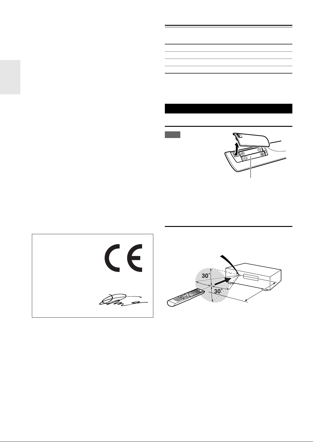
Using the Remote Controller
Installing the Batteries
Note
• If the remote controller
doesn’t work reliably, try
replacing the batteries.
• Don’t mix new and old
batteries or different
types of batteries.
• If you intend not to use
the remote controller for
a long time, remove the batteries to prevent damage from leakage or corrosion.
• Remove expired batteries as soon as possible to prevent damage
from leakage or corrosion.
Batteries (AA/R6)
For European Models
Declaration of Conformity
We,
ONKYO EUROPE
ELECTRONICS GmbH
LIEGNITZERSTRASSE 6,
82194 GROEBENZELL,
GERMANY
declare in own responsibility, that the ONKYO product
described in this instruction manual is in compliance with the
corresponding technical standards such as EN60065,
EN55013, EN55020 and EN61000-3-2, -3-3.
GROEBENZELL, GERMANY
K. MIYAGI
ONKYO EUROPE ELECTRONICS GmbH
Aiming the Remote Controller
To use the remote controller, point it at the AV receiver’s
remote control sensor, as shown below.
Remote control sensor
AV r eceiver
Approx. 16 ft. (5 m)
En
4
Page 5

Contents
Introduction
Important Safety Instructions ......................................... 2
Precautions....................................................................... 3
Supplied Accessories...................................................... 4
Using the Remote Controller .......................................... 4
Features ............................................................................6
Front & Rear Panels......................................................... 7
Front Panel..................................................................... 7
Display............................................................................ 8
Rear Panel ..................................................................... 8
Remote Controller............................................................ 9
Controlling the AV Receiver ...........................................9
About Home Theater...................................................... 10
Enjoying Home Theater................................................ 10
Connections
Connecting the AV Receiver ......................................... 11
Connecting Your Speakers .......................................... 11
About AV Connections .................................................14
Connecting Your Components with HDMI.................... 15
Connecting Your Components ..................................... 16
Connecting Onkyo u Components ............................ 17
Connecting Antenna..................................................... 18
Which Connections Should I Use?............................... 18
Turning On & Basic Operations
Turning On/Off the AV Receiver ................................... 20
Turning On ................................................................... 20
Turning Off ................................................................... 20
Basic Operations............................................................ 21
Selecting the Language Used
for the Onscreen Setup Menus.................................. 21
Playing the Connected Component.............................. 21
Displaying Source Information ..................................... 21
Setting the Display Brightness ..................................... 21
Muting the AV Receiver................................................ 22
Using the Sleep Timer.................................................. 22
Selecting Speaker Layout ............................................ 22
Using the Audio and Video Menus ............................... 22
Changing the Input Display ..........................................23
Using Headphones....................................................... 23
Audyssey 2EQ
and Speaker Setup .................................................... 23
Listening to the Radio ................................................... 26
Using the Tuner............................................................ 26
Presetting FM/AM Stations........................................... 27
Using RDS (European models) .................................... 27
Recording ....................................................................... 29
Using the Listening Modes ........................................... 30
Selecting Listening Modes ........................................... 30
About Listening Modes................................................. 31
®
Room Correction
Advanced Operations
Advanced Setup .............................................................36
On-screen Setup Menus............................................... 36
Common Procedures in Setup Menu ...........................36
Input/Output Assign ......................................................37
Speaker Setup.............................................................. 39
Audio Adjust .................................................................42
Source Setup................................................................ 43
Listening Mode Preset.................................................. 47
Miscellaneous............................................................... 48
Hardware Setup............................................................ 49
Lock Setup.................................................................... 50
Using the Audio Settings ..............................................50
Zone 2.............................................................................. 53
Connecting Zone 2 .......................................................53
Setting the Powered Zone 2 .........................................54
Using Zone 2 ................................................................54
Controlling iPod & Other Components
Controlling iPod ............................................................. 56
Connecting an Onkyo Dock.......................................... 56
Using the Onkyo Dock.................................................. 57
Controlling Your iPod.................................................... 58
Controlling Other Components.....................................60
Preprogrammed Remote Control Codes ......................60
Looking up for Remote Control Code ...........................60
Entering Remote Control Codes................................... 61
Remote Control Codes for Onkyo Components
Connected via u...................................................... 61
Resetting REMOTE MODE Buttons .............................62
Resetting the Remote Controller ..................................62
Controlling Other Components .....................................62
Others
Troubleshooting .............................................................64
Specifications .................................................................69
About HDMI..................................................................... 70
Using an RIHD-compatible TV, Player, or Recorder ... 71
Video Resolution Chart..................................................73
To reset the AV receiver to its factory defaults, turn it
on and, while holding down VCR/DVR, press
ON/STANDBY (➔ 64).
En
5
Page 6
Features
Amplifier
• 130 Watts/Channel @ 6 ohms
• WRAT–Wide Range Amplifier Technology
(5 Hz to 100 kHz bandwidth)
• Optimum Gain Volume Circuitry
• H.C.P.S. (High Current Power Supply) Massive High
Power Transformer
Processing
•THX*1 Integrated System Certified
• THX Surround EX
*1
, THX I/S*1 Cinema, THX Music
Mode
• HDMI Video Upscaling (to 1080p Compatible) with
Faroudja DCDi Cinema Enhancement
• HDMI (Ver.1.4a with Audio Return Channel, 3D), DeepColor, x.v.Color
*
, Lip Sync, DTS*2-HD Master Audio,
DTS-HD High Resolution Audio, Dolby TrueHD*3,
Dolby Digital Plus, DSD and Multi-CH PCM
*3
• Dolby Pro Logic IIz
– New Surround Format (front-
high)
• Non-Scaling Configuration
•A-Form Listening Mode Memory
• Direct Mode
• Music Optimizer
*4
for Compressed Digital Music files
• 192 kHz/24-bit D/A Converters
• Powerful and Highly Accurate 32-bit Processing DSP
• Jitter Cleaning Circuit Technology
Connections
• 4 HDMI*5 Inputs and 1 Output
• Onkyo p for System Control
• 4 Digital Inputs (2 Optical/2 Coaxial)
• Component Video Switching (2 Inputs/1 Output)
• Front “Line in” Input for Portable audio player
• Universal Port for the Dock for iPod
*
/HD Radio™*6
tuner module (North American models)/DAB+ tuner
module (European models)
• Banana Plug-Compatible Speaker Posts
*7
• Powered Zone 2
Miscellaneous
• 40 FM/AM Presets
• Audyssey 2EQ
• Audyssey Dynamic EQ
• Audyssey Dynamic Volume
Listening Level and Dynamic Range
• Crossover Adjustment
(40/50/60/70/80/90/100/120/150/200 Hz)
• A/V Sync Control Function (up to 200 ms)
• On-Screen Display via HDMI
• Preprogrammed u-Compatible Remote
®*8
to Correct Room Acoustic Problems
®*8
for Loudness Correction
®*8
to Maintain Optimal
*1
THX and the THX logo are trademarks of THX Ltd. which
are registered in some jurisdictions. All rights reserved.
*2
Manufactured under license under U.S. Patent #'s: 5,451,942;
5,956,674; 5,974,380; 5,978,762; 6,226,616; 6,487,535;
7,212,872; 7,333,929; 7,392,195; 7,272,567 & other U.S. and
worldwide patents issued & pending. DTS and the Symbol are
registered trademarks, & DTS-HD, DTS-HD Master Audio,
and the DTS logos are trademarks of DTS, Inc. Product
includes software.
© DTS, Inc. All Rights Reserved.
*3
Manufactured under license from Dolby Laboratories.
“Dolby”, “Pro Logic”, “Surround EX” and the double-D symbol are trademarks of Dolby Laboratories.
*4
Music Optimizer™ is a trademark of Onkyo Corporation.
*5
“HDMI, the HDMI Logo, and High-Definition Multimedia
Interface are trademarks or registered trademarks of HDMI
Licensing LLC in the United States and other countries.”
*6
HD Radio™ and the HD Radio Ready logo are proprietary
trademarks of iBiquity Digital Corporation.
To receive HD Radio broadcasts, you must install an Onkyo
UP-HT1 HD Radio tuner module (sold separately).
*7
In Europe, using banana plugs to connect speakers to an audio
amplifier is prohibited.
*8
Manufactured under license from Audyssey Laboratories™.
U.S. and foreign patents pending. Audyssey 2EQ
Audyssey Dynamic Volume
are registered trademarks and trademarks of
Audyssey Laboratories.
®
®
and Audyssey Dynamic EQ®
,
THX
The HT-R980, jointly developed by Onkyo and THX
Ltd., provides home theater enthusiasts the perfect blend
of performance and ease of use. All of the components in
this THX Certified System are engineered to work seamlessly together to deliver exceptional entertainment experiences. Whether you are watching a movie, listening to
music, or playing the hottest new video game, the
HT-R980 will transform your room into the ultimate
entertainment environment.
*
iPod is a trademark of Apple Inc., registered in the U.S. and
other countries.
*
“x.v.Color” is a trademark of Sony Corporation.
En
6
Page 7
Front & Rear Panels
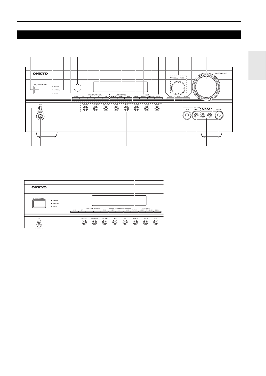
Front Panel
North American models
a
r
q
European models
bcde fhg ijklmno p
stuwv
x
The actual front panel has various logos printed on it. They are not shown here for clarity.
The page numbers in parentheses show where you can find the main explanation for each item.
a ON/STANDBY button (➔ 20)
b STANDBY indicator (➔ 20)
c HDMI THRU indicator (➔ 50)
d ZONE 2 indicator (➔ 54)
e Remote control sensor (➔ 4)
f ZONE 2, OFF, ZONE 2 LEVEL/TONE LEVEL
and TONE buttons (➔ 51, 54 to 55)
g Display (➔ 8)
h LISTENING MODE buttons (MOVIE/TV, MUSIC
and GAME) (➔ 30)
i DIMMER button (North American models) (➔ 21)
j MEMORY button (➔ 27)
k TUNING MODE button (➔ 26)
l DISPLAY button (➔ 21)
m SETUP button (➔ 36)
n TUNING, PRESET (➔ 26 to 27), arrow and
ENTER buttons
o RETURN button
p MASTER VOLUME control (➔ 21)
q THX button (➔ 30)
r PHONES jack (➔ 23)
s Input selector buttons (BD/DVD, VCR/DVR,
CBL/SAT, GAME, AUX, TUNER, TV/CD and
PORT) (➔ 21)
t AUX INPUT LINE IN jack (➔ 16)
u AUX INPUT VIDEO jack (➔ 16)
v AUX INPUT AUDIO jacks (➔ 16)
w SETUP MIC jack (➔ 24)
x RT/PTY/TP button (European models) (➔ 27)
En
7
Page 8
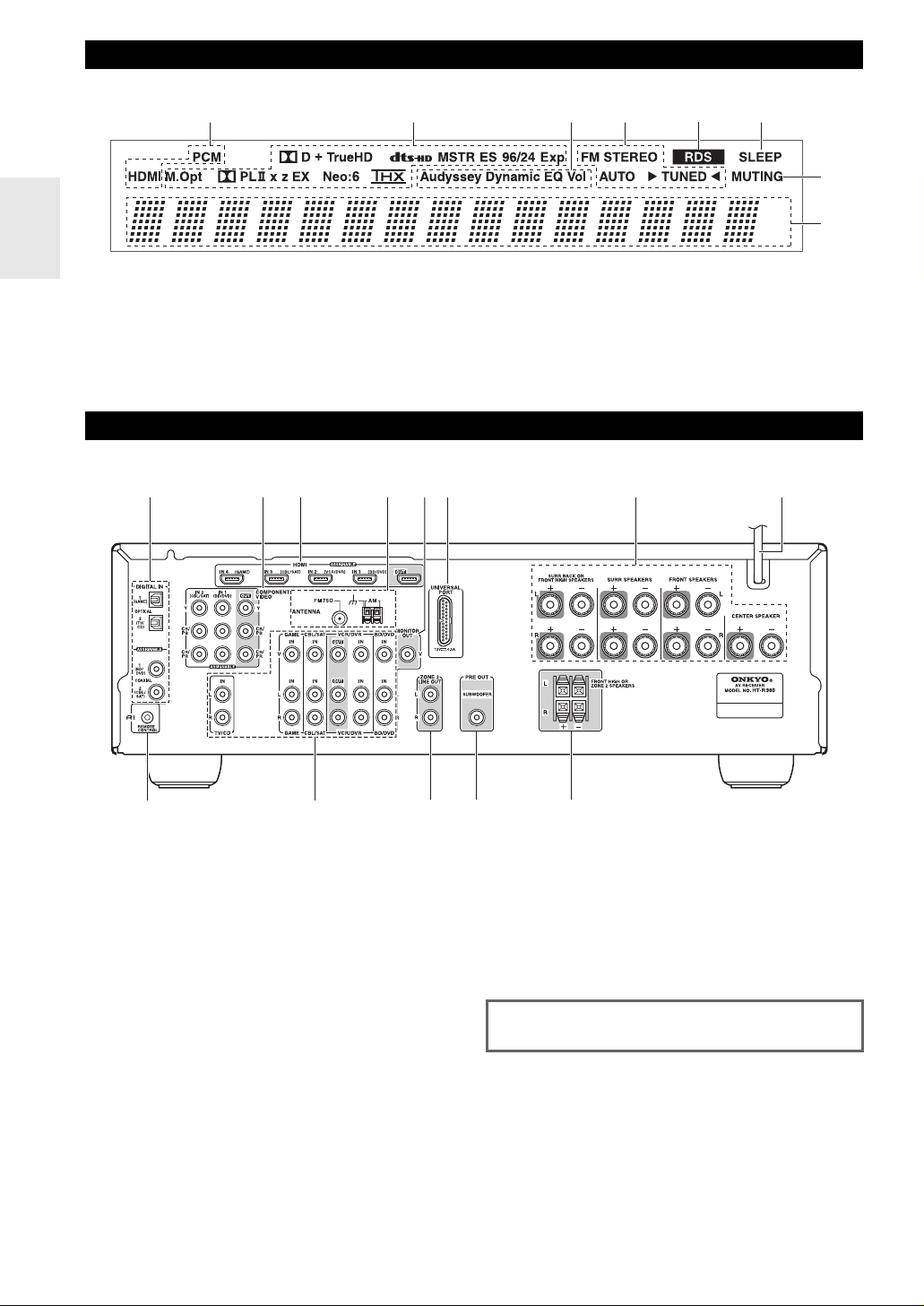
Display
ab ef
For detailed information, see the pages in parentheses.
a Audio input indicators
b Listening mode and format indicators (➔ 30, 51)
c Audyssey indicators (➔ 23, 40, 43)
d Tuning indicators (➔ 26)
Rear Panel
acb
d
ef
cd
e RDS indicator (European models) (➔ 27)
f SLEEP indicator (➔ 22)
g MUTING indicator (➔ 22)
h Message area
g
h
g
h
i
a DIGITAL IN OPTICAL and COAXIAL jacks
b COMPONENT VIDEO IN and OUT jacks
c HDMI IN and OUT jacks
d FM ANTENNA jack and AM ANTENNA terminal
e MONITOR OUT V jack
f UNIVERSAL PORT jack
g SPEAKERS terminals
(CENTER, FRONT, SURR and SURR BACK OR
FRONT HIGH)
h Power cord
i u REMOTE CONTROL jack
En
jklm
8
j Composite video and analog audio jacks
(BD/DVD IN, VCR/DVR IN and OUT, CBL/SAT IN,
GAME IN and TV/CD IN)
k ZONE 2 LINE OUT jacks
l SUBWOOFER PRE OUT jack
m FRONT HIGH OR ZONE 2 SPEAKERS terminals
See “Connecting the AV Receiver” for connection information (➔ 11 to 19).
Page 9
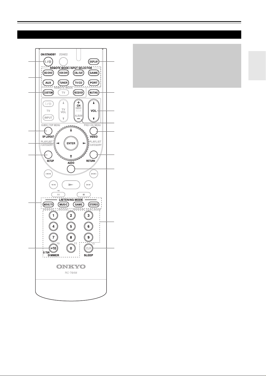
Remote Controller
Controlling the AV Receiver
a
b
h
c
To control the AV receiver, press RECEIVER to select
Receiver mode.
You can also use the remote controller to control
Onkyo Blu-ray Disc/DVD player, CD player and
other components.
See “Entering Remote Control Codes” for more
details (➔ 61).
*1
c
d
a
e
f
g
b
i
j
d
k
l
m
e
n
For detailed information, see the pages in parentheses.
a ON/STANDBY button (➔ 20)
b REMOTE MODE/INPUT SELECTOR buttons
(BD/DVD, VCR/DVR, CBL/SAT, GAME, AUX,
TUNER, TV/CD and PORT) (➔ 21)
c SP LAYOUT button (➔ 22)
*2
d Arrow q/w/e/r and ENTER buttons
e SETUP button (➔ 36)
f LISTENING MODE buttons (MOVIE/TV, MUSIC,
GAME and STEREO) (➔ 30)
g DIMMER button (➔ 21)
h DISPLAY button (➔ 21)
*3
i MUTING button (➔ 22)
j VOL q/w button (➔ 21)
k VIDEO button (➔ 22)
l RETURN button
m AUDIO button (➔ 22)
n SLEEP button (➔ 22)
■ Controlling the tuner
To control the AV receiver’s tuner, press TUNER (or
RECEIVER).
You can select AM or FM by pressing TUNER repeatedly.
a Arrow q/w buttons (➔ 26)
b D.TUN button (➔ 26)
c DISPLAY button
d CH +/– button (➔ 27)
e Number buttons (➔ 26)
*1
To control component, you must first enter remote control
code.
See “Entering Remote Control Codes” for more details
(➔ 61)
*2
This button acts as a shortcut for the Video menu (➔ 22)
*3
This button acts as a shortcut for the Audio menu (➔ 22)
En
9
Page 10
About Home Theater
Enjoying Home Theater
Thanks to the AV receiver’s superb capabilities, you can enjoy surround sound with a real sense of movement in your
own home—just like being in a movie theater or concert hall. With Blu-ray Discs or DVDs, you can enjoy DTS and
Dolby Digital. With analog or digital TV, you can enjoy Dolby Pro Logic IIx, DTS Neo:6, or Onkyo’s original DSP listening modes.
And you can use THX Surround EX to expand 5.1-channel sources for 7.1-channel playback.
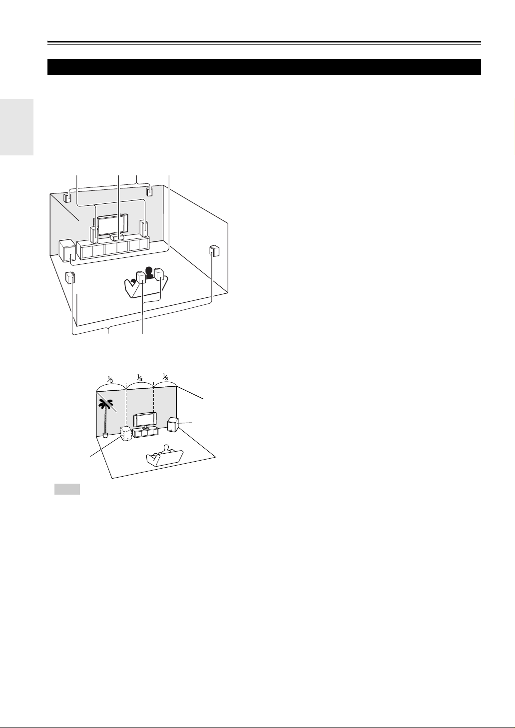
abFront speakers
These output the overall sound. Their role in a home theater is to pro-
ijab c
de
1/3 of wall
position
Tip
• To find the best position for your subwoofer, while
playing a movie or some music with good bass,
experiment by placing your subwoofer at various
positions within the room, and choose the one that
provides the most satisfying results.
gh
f
Corner
position
vide a solid anchor for the sound image. They should be positioned
facing the listener at about ear level, and equidistant from the TV.
Angle them inward so as to create a triangle, with the listener at the
apex.
c Center speaker
This speaker enhances the front speakers, making sound movements
distinct and providing a full sound image. In movies it’s used mainly
for dialog. Position it close to your TV facing forward at about ear
level, or at the same height as the front speakers.
deSurround speakers
These speakers are used for precise sound positioning and to add realistic ambience. Position them at the sides of the listener, or slightly
behind, about 2 to 3 feet (60 to 100 cm) above ear level. Ideally they
should be equidistant from the listener.
f Subwoofer
The subwoofer handles the bass sounds of the LFE (Low-Frequency
Effects) channel. The volume and quality of the bass output from your
subwoofer will depend on its position, the shape of your listening
room, and your listening position. In general, a good bass sound can be
obtained by installing the subwoofer in a front corner, or at one-third
the width of the wall, as shown.
ghSurround back speakers
These speakers are necessary to enjoy Dolby Digital EX, DTS-ES
Matrix, DTS-ES Discrete, THX Surround EX, etc. They enhance the
realism of surround sound and improve sound localization behind the
listener. Position them behind the listener about 2 to 3 feet (60 to
100 cm) above ear level.
ijFront high speakers
These speakers are necessary to enjoy Dolby Pro Logic IIz Height.
They significantly enhance the spatial experience. Position them at
least 3.3 feet (100 cm) above the front speakers (preferably as high as
possible) and at an angle slightly wider than the front speakers.
En
10
Page 11
Connections
Connecting the AV Receiver
Connecting Your Speakers
Speaker Configuration
The following table indicates the channels you should use
depending on the number of speakers that you have.
For 7.1-channel surround-sound playback, you need 7
speakers and a powered subwoofer.
Number of channels 234567789
Front speakers ✔✔✔✔✔✔✔✔✔
Center speaker ✔ ✔✔✔✔✔✔
Surround speakers ✔✔✔✔✔✔✔
Surround back speaker
Surround back speakers
Front high speakers
*1
If you’re using only one surround back speaker, connect it to
the SURR BACK OR FRONT HIGH L terminals.
*2
Front high and surround back speakers cannot be used at the
same time.
*3
(North American models) When you connect the front high
left and right speakers, prepare for it separately, or use the surround back left and right speakers.
*1*2
*2
*2*3
No matter how many speakers you use, a powered subwoofer is recommended for a really powerful and solid
bass.
To get the best from your surround sound system, you
need to set the speaker settings. You can do this automatically (➔ 24) or manually (➔ 39).
✔✔
✔✔
✔✔✔
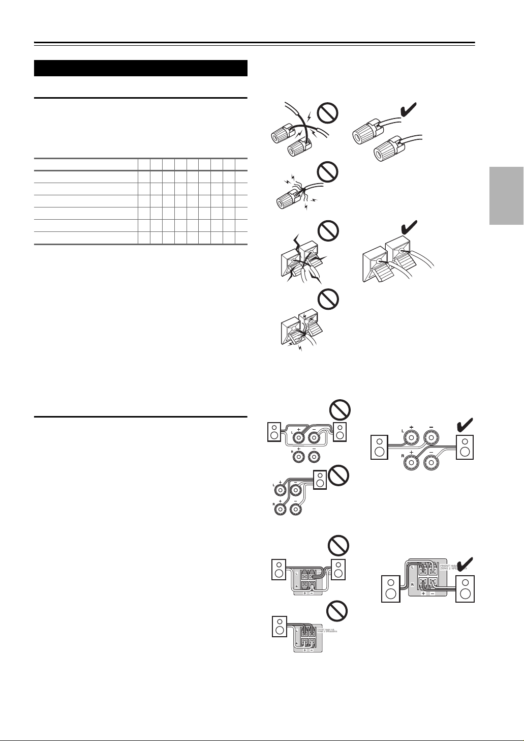
• Make sure the metal core of the wire does not have contact with the AV receiver’s rear panel. Doing so may
damage the AV receiver.
• Don’t connect more than one cable to each speaker terminal. Doing so may damage the AV receiver.
• Don’t connect one speaker to several terminals.
Speaker Connection Precautions
Read the following before connecting your speakers:
• You can connect speakers with an impedance of between
6 and 16 ohms. If you use speakers with a lower impedance, and use the amplifier at high volume levels for a
long period of time, the built-in amp protection circuit
may be activated.
• Disconnect the power cord from the wall outlet before
making any connections.
• Read the instructions supplied with your speakers.
• Pay close attention to speaker wiring polarity. In other
words, connect positive (+) terminals only to positive (+)
terminals, and negative (–) terminals only to negative (–)
terminals. If you get them the wrong way around, the
sound will be out of phase and will sound unnatural.
• Unnecessarily long, or very thin speaker cables may
affect the sound quality and should be avoided.
• Be careful not to short the positive and negative wires.
Doing so may damage the AV receiver.
En
11
Page 12
Connecting the Speaker Cables
Screw-type speaker terminals
Strip 1/2" to 5/8" (12 to 15 mm) of
insulation from the ends of the
speaker cables, and twist the bare
wires tightly, as shown. (Supplied
speaker cables are already stripped.)
Using Banana Plugs (North American models)
• If you are using banana plugs, tighten the speaker terminal before inserting the banana plug.
• Do not insert the speaker code directly into the center hole of the speaker terminal.
Push-type speaker terminals
Strip 3/8" to 1/2" (10 to 12 mm) of insulation from the ends of
the speaker cables, and twist the bare wires tightly, as shown.
(Supplied speaker cables are already stripped.)
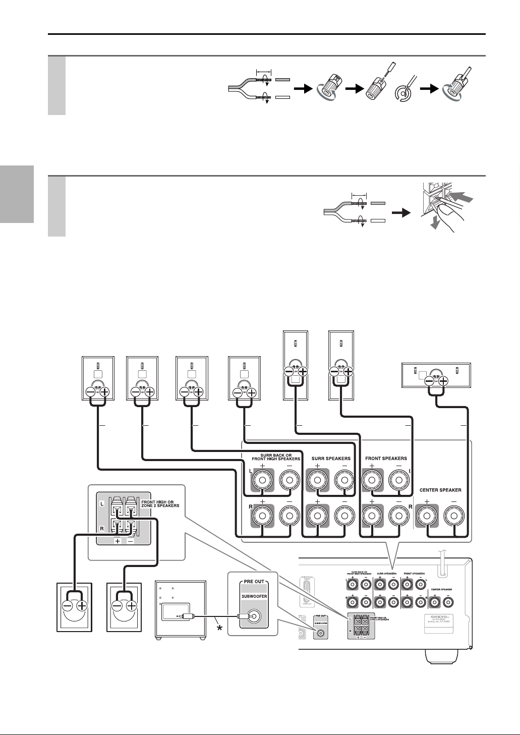
The following illustration shows which speaker should be connected to each pair of terminals. If you’re using only one
surround back speaker, connect it to the SURR BACK OR FRONT HIGH L terminals.
■ North American models
1/2" to 5/8"(12 to 15 mm)
3/8" to 1/2"(10 to 12 mm)
Surround
back right
speaker
Surround
back left
speaker
BrownTa n
Surround
right
speaker
Surround
left
speaker
Front right
speaker
Front left
speaker
RedBlueGray Green
White
Center speaker
En
12
Front high
right
speaker
(Optional)
Front high
left
speaker
(Optional)
Powered
subwoofer
Page 13
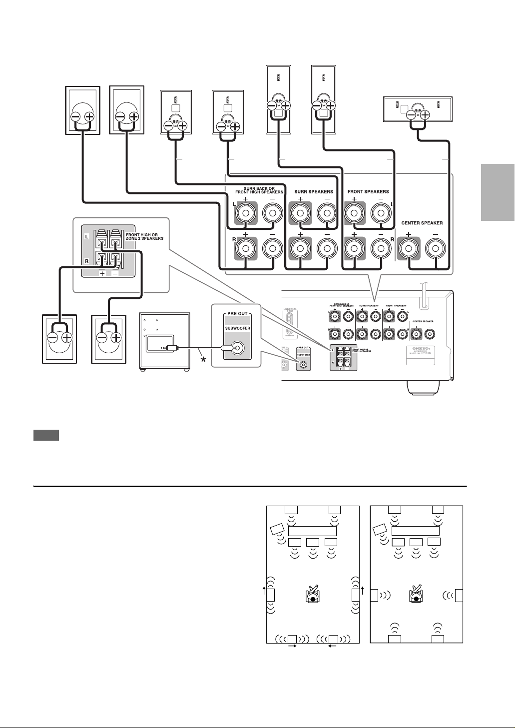
■ European models
Surround
back right
speaker
(Optional)
Surround
back left
speaker
(Optional)
Surround
right
speaker
Surround
left
speaker
Front right
speaker
Front left
speaker
RedBlueGray Green
White
Center speaker
Front high
right
speaker
(Optional)
*
Using the supplied RCA cable, connect the subwoofer’s LINE INPUT jack to your AV receiver’s SUBWOOFER PRE OUT jack.
Note
• The front high speakers can also be connected to the SURR BACK OR FRONT HIGH SPEAKERS terminals. When doing so, set
“Surr Back/Front High” in Speaker Setup to “Front High” (➔ 39).
Front high
left
speaker
(Optional)
Powered
subwoofer
Using Dipole Speakers
You can use dipole speakers for the surround and surround
back speakers. Dipole speakers output the same sound in two
directions.
Dipole speakers typically have an arrow printed on them to
indicate how they should be positioned. The surround dipole
speakers should be positioned so that their arrows point
toward the TV/screen, while the surround back dipole speakers should be positioned so that their arrows point toward
each other, as shown.
abFront speakers
c Center speaker
deSurround speakers
f Subwoofer
ghSurround back speakers
ijFront high speakers
Dipole speakers
ij
f
TV/screen TV/screen
cba
de
gh
Normal speakers
ij
f
abc
de
gh
En
13
Page 14

About AV Connections
Connected image with AV components
HDMI cable Other cables
: Video & Audio
AV receiverAV receiver
TV, projector, etc.
Blu-ray Disc/
DVD player
Game console
TV, projector, etc.
Blu-ray Disc/
DVD player
• Before making any AV connections, read the manuals supplied with your AV components.
• Don’t connect the power cord until you’ve completed and double-checked all AV connections.
• Push plugs in all the way to make good connections (loose connections can cause noise or malfunctions).
• To prevent interference, keep audio and video cables away from power cords and speaker cables.
AV Cables and Jacks
Signal Cable Jack Description
Video and
Audio
HDMI HDMI connections can carry digital video and audio.
HDMI
: Video
: Audio
Game console
Right!
Wrong!
Video Component video Component video separates the luminance (Y) and color
Composite video Composite video is commonly used on TVs, VCRs, and
Audio Optical digital
audio
Y
P
B/CB
PR/CR
Green
Blue
Red
V
Yellow
OPTICAL
difference signals (P
ture quality (some TV manufacturers label their component video sockets slightly differently).
other video equipment.
Optical digital connections allow you to enjoy digital
sound such as PCM
B/CB, PR/CR), providing the best pic-
*
, Dolby Digital or DTS. The audio
quality is the same as coaxial.
Coaxial digital
audio
Orange
Coaxial digital connections allow you to enjoy digital
sound such as PCM
*
, Dolby Digital or DTS. The audio
quality is the same as optical.
Analog audio
(RCA)
1/8" (3.5 mm)
L
White
R
Red
Analog audio connections (RCA) carry analog audio.
This cable carries analog audio.
Stereo mini plug
*
Available sampling rate for PCM input signal is 32/44.1/48/88.2/96 kHz. Even 176.4/192 kHz is effective in case of the HDMI connection.
Note
• The AV receiver does not support SCART plugs.
• The AV receiver’s optical digital jacks have shutter-type covers that open when an optical plug is inserted and close when it’s removed.
Push plugs in all the way.
Caution
• To prevent shutter damage, hold the optical plug straight when inserting and removing.
En
14
Page 15
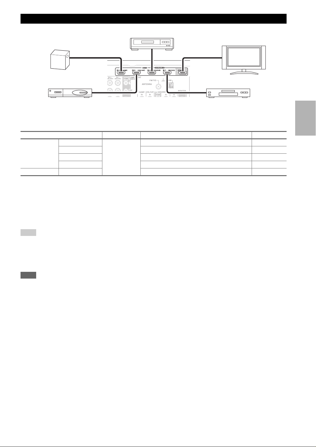
Connecting Your Components with HDMI
VCR or DVD recorder/Digital Video Recorder
Game console
Satellite, cable, set-top box, etc. Blu-ray Disc/DVD player
TV, projector, etc.
Connect your components to the appropriate jacks. The default input assignments are shown below.
✔: Assignment can be changed (➔ 37).
Jack Signal Components Assignable
Input HDMI IN 1 Audio/Video Blu-ray Disc/DVD player ✔
HDMI IN 2 VCR or DVD recorder/Digital Video Recorder ✔
HDMI IN 3 Satellite, cable, set-top box, etc. ✔
HDMI IN 4 Game console ✔
Output HDMI OUT TV, projector, etc.
Refer to “About HDMI” (➔ 70) and “Using an RIHD-compatible TV, Player, or Recorder” (➔ 71).
■ Audio return channel (ARC) function
Audio return channel (ARC) function enables an HDMI capable TV to send the audio stream to the HDMI OUT of the
AV receiver. To use this function, you must select the TV/CD input selector.
• To use ARC function, you must select the TV/CD input selector, your TV must support ARC function and “HDMI
Control (RIHD)” is set to “On”(
Tip
• To listen to audio received by the HDMI IN jacks through your TV’s speakers:
– Set the “TV Control” setting to “On” (➔ 50) for an p-compatible TV.
– Set the “Audio TV Out” setting to “On” (➔ 49) when the TV is not compatible with p or the “TV Control” setting to “Off”.
– Set your Blu-ray Disc/DVD player’s HDMI audio output setting to PCM.
– To listen to TV audio through the AV receiver, see “Connecting Your Components” (➔ 16).
Note
• When listening to an HDMI component through the AV receiver, set the HDMI component so that its video can be seen on the TV
screen (on the TV, select the input of the HDMI component connected to the AV receiver). If the TV power is off or the TV is set to
another input source, this may result in no sound from the AV receiver or the sound may be cut off.
•When the “Audio TV Out” setting is set to “On” (➔ 49) to hear from your TV’s speakers, by controlling the AV receiver’s volume,
the sound will be output from the AV receiver’s speakers, too. When the
speakers of p-compatible TV, by controlling the AV receiver’s volume, the AV receiver’s speakers will produce sound while the
TV’s speakers are muted. To stop the AV receiver’s speakers producing sound, change the settings, change your TV’s settings, or turn
down the AV receiver’s volume.
➔ 49).
“TV Control” setting is set to “On” (➔ 50) to hear from
En
15
Page 16

Connecting Your Components
The on-screen setup menus appear only on a TV that is connected to the HDMI OUT. If your TV is connected to
the MONITOR OUT V or the COMPONENT VIDEO OUT, use the AV receiver’s display when changing settings.
Front Rear
A EB DC
Connect your components to the appropriate jacks. The default input assignments are shown below.
✔: Assignment can be changed (➔ 38).
No. Jack Signal Components Assignable
AUX INPUT LINE IN Analog audio Portable audio player
A
VIDEO Composite video Camcorder, etc
AUDIO L/R Analog audio
COMPONENT
B
VIDEO
DIGITAL IN OPTICAL IN 1 (GAME) Digital audio Game console ✔
C
MONITOR OUT Composite video TV, projector, etc.
D
BD/DVD IN Analog audio and
VCR/DVR IN VCR or DVD recorder/Digital
CBL/SAT IN Satellite, cable, set-top box, etc.
GAME IN Game console
TV/CD IN Analog audio
UNIVERSAL PORT Analog audio/
E
IN 1 (BD/DVD) Component video Blu-ray Disc/DVD player ✔
IN 2 (CBL/SAT) Satellite, cable, set-top box, etc. ✔
OUT TV, projector, etc.
IN 2 (TV/CD) TV, CD player ✔
COAXIAL IN 1 (BD/DVD) Blu-ray Disc/DVD player ✔
IN 2 (CBL/SAT) Satellite, cable, set-top box, etc. ✔
composite video
Vid eo
Blu-ray Disc/DVD player
Video Recorder
*1
TV, CD player, Turntable
Cassette tape deck, MD, CD-R
Universal port optional dock
(UP-A1 etc.)
,
Note
*1
Connect a turntable (MM) that has a phono preamp built-in. If your turntable (MM) doesn’t have it, you’ll need a commercially
available phono preamp.
If your turntable has a moving coil (MC) type cartridge, you’ll need a commercially available MC head amp or MC transformer as
well as a phono preamp. See your turntable’s manual for details.
• When you connect to both AUX INPUT AUDIO jacks and AUX INPUT LINE IN jack at the same time, AUX INPUT LINE IN jack
will be given a higher priority.
• The AV receiver can output audio and video signals from the AUX INPUT jacks to the VCR/DVR OUT jacks.
• With connection D, you can listen and record audio from the external components while you are in Zone 2. You can listen and record
audio from the external components in the main room; you can listen to the audio in Zone 2 as well.
• With connection C, you can enjoy Dolby Digital and DTS. (To record or listen in Zone 2 as well, use C and D.)
• With connection D, if your Blu-ray Disc/DVD player has both the main stereo and multichannel outputs, be sure to connect the main
stereo.
■ How to record the video
With the connections described above, you cannot record the video through the AV receiver. To make a connection for
video recording (➔ 29).
En
16
Page 17

Connecting Onkyo u Components
Step 1:
Make sure that each Onkyo component is connected
with an analog audio cable (connection D in the hookup
examples) (➔ 16).
Step 2:
Make the u connection (see illustration below).
Step 3:
If you’re using an RI Dock, or cassette tape deck,
change the Input Display (➔ 23).
With u (Remote Interactive), you can use the following
special functions:
■ System On/Auto Power On
When you start playback on a component connected via
u while the AV receiver is on Standby, the AV
receiver will automatically turn on and select that component as the input source.
■ Direct Change
When playback is started on a component connected via
u, the AV receiver automatically selects that compo-
nent as the input source.
■ Remote Control
You can use the AV receiver’s remote controller to control your other u-capable Onkyo components, point-
ing the remote controller at the AV receiver’s remote
control sensor instead of the component. You must enter
the appropriate remote control code first (➔ 61).
Note
•Use only u cables for u connections. u cables are supplied
with Onkyo players (DVD, CD, etc.).
• Some components have two u jacks. You can connect either
one to the AV receiver. The other jack is for connecting addi-
tional u-capable components.
• Connect only Onkyo components to u jacks. Connecting other
manufacturer’s components may cause a malfunction.
• Some components may not support all u functions. Refer to
the manuals supplied with your other Onkyo components.
• While Zone 2 is on, the System On/Auto Power On and Direct
Change u functions do not work.
• Do not use u connections if you use HDMI Control (RIHD)
(➔ 49).
IN
L
R
TV/CD
IN
L
REMOTE
CONTROL
e.g., CD player
e.g., DVD player
ANALOG
AUDIO OUT
ANALOG
AUDIO OUT
R
BD/DVD
LR
LR
En
17
Page 18
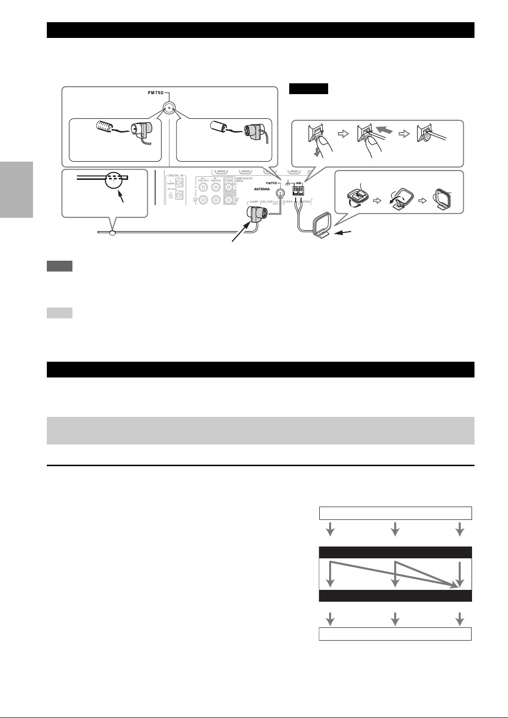
Connecting Antenna
This section explains how to connect the supplied indoor FM antenna and AM loop antenna.
The AV receiver won’t pick up any radio signals without any antenna connected, so you must connect the antenna to use
the tuner.
North American
models
European models
Caution
• Be careful that you don’t injure yourself when
using thumbtacks.
Insert the plug fully
into the jack.
Thumbtacks, etc.
Indoor FM antenna (supplied)
Note
• Once your AV receiver is ready for use, you’ll need to tune into a radio station and position the antenna to achieve the best possible
reception.
• Keep the AM loop antenna as far away as possible from your AV receiver, TV, speaker cables, and power cords.
Tip
• If you cannot achieve good reception with the supplied indoor FM antenna, try a commercially available outdoor FM antenna instead.
• If you cannot achieve good reception with the supplied indoor AM loop antenna, try using it with a commercially available outdoor AM
antenna.
Insert the plug fully
into the jack.
Push. Insert wire. Release.
Assembling the AM loop antenna.
AM loop antenna (supplied)
Which Connections Should I Use?
The AV receiver supports several connection formats for compatibility with a wide range of AV equipment. The format
you choose will depend on the formats supported by your components. Use the following sections as a guide.
The on-screen setup menus appear only on a TV that is connected to the HDMI OUT. If your TV is connected to
the MONITOR OUT V or the COMPONENT VIDEO OUT, use the AV receiver’s display when changing settings.
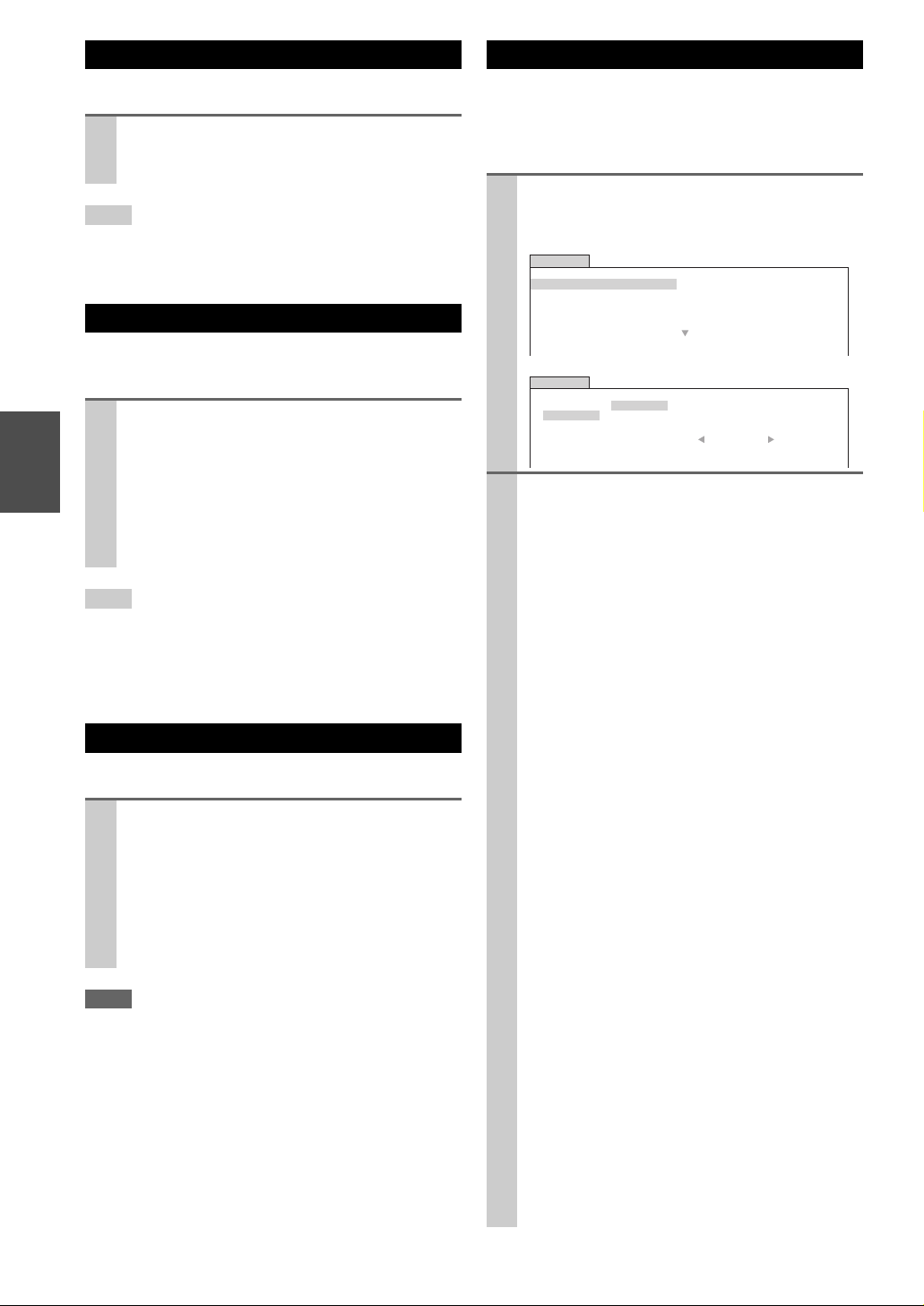
Video Connection Formats
Video component can be connected by using any one of the following video connection formats: composite video, component video, or HDMI, the latter offering the best picture quality.
For optimal video performance, THX recommends that
video signals pass through the system without upconver-
Video Signal Flow Chart
Blu-ray Disc/DVD player, etc.
sion (e.g., component video input through to component
video output).
To by-pass video upconversion in the AV receiver, simultaneously press the VCR/DVR and RETURN on the AV
Composite
Component
IN
receiver. While continuing to hold down the VCR/DVR,
press RETURN to toggle until “Skip” appears on the dis-
AV recei ver
play. Release both buttons.
To use the video upconversion in the AV receiver, repeat
the above process until “Use” appears on the display and
Composite
MONITOR OUT
Component
release the buttons.
Video input signals flow through the AV receiver as shown,
TV, projector, etc.
with composite video and component video sources all being
upconverted for the HDMI output.
The composite video and component video outputs pass through their respective input signals as they are.
When you connect audio component to an HDMI or COMPONENT input, you must assign that input to an input selector
En
(➔ 37, 38).
18
HDMI
HDMI
Page 19

■ Signal Selection
If signals are present at more than one input, the inputs will
be selected automatically in the following order of priority:
HDMI, component video, composite video.
However, for component video only, regardless of whether a
component video signal is actually present, if a component
video input is assigned to the input selector, that component
video input will be selected. And if no component video
input is assigned to the input selector, this will be interpreted
as no component video signal being present.
In the Signal Selection Example shown on the right, video
signals are present at both the HDMI and composite video
inputs, however, the HDMI signal is automatically selected
as the source and video is output by the HDMI outputs.
Audio Connection Formats
Audio component can be connected by using any of the
following audio connection formats: analog, optical, coaxial, or HDMI.
When choosing a connection format, bear in mind that the
AV receiver does not convert digital input signals for analog line outputs and vice versa. For example, audio signals
connected to an optical or coaxial digital input are not output by the analog VCR/DVR OUT.
If signals are present at more than one input, the inputs
will be selected automatically in the following order of priority: HDMI, digital, analog.
Signal Selection Example
Blu-ray Disc/DVD player, etc.
Composite
AV recei ver
Composite
Audio Signal Flow Chart
Blu-ray Disc/DVD player, etc.
AV r eceiver
*1
Depends on the “Audio TV Out” setting (➔ 49).
*2
This setting is available, when “Audio Return Channel”
setting is set to “Auto” (➔ 50), you must select the TV/CD
input selector and your TV must support ARC function.
1
*
Component
IN
MONITOR OUT
Component
TV, projector, etc.
Optical
IN
1
*
OUT
TV, projector, etc.
1
*
HDMI
HDMI
HDMICoaxial Analog
HDMI Analog
*1*
2
En
19
Page 20

Turning On & Basic Operations
Turning On/Off the AV Receiver
ON/STANDBY
STANDBY indicator
ON/STANDBY
RECEIVER
Turning On
Press ON/STANDBY on the front panel.
or
Press RECEIVER followed by ON/STANDBY on the remote controller.
The AV receiver comes on, the display lights, and the STANDBY indicator goes off.
Turning Off
Press ON/STANDBY on the front panel or the remote controller.
The AV receiver will enter Standby mode. To prevent any loud surprises when you turn on the AV receiver, always
turn down the volume before you turn it off.
En
20
Page 21

Basic Operations
The on-screen menus appear only on a TV that is connected to the HDMI OUT. If your TV is connected to
the MONITOR OUT V or the COMPONENT VIDEO
OUT, use the AV receiver’s display when changing
settings.
This manual describes the procedure using the
remote controller unless otherwise specified.
Selecting the Language Used for the Onscreen Setup Menus
You can determine the language used for the onscreen
setup menus. See “Language” in the “OSD Setup”
(➔ 48).
Playing the Connected Component
■ Operating on the AV receiver
Use the input selector buttons to select the input
1
source.
Start playback on the source component.
2
See also:
• “Controlling Other Components” (➔ 60)
• “Controlling iPod” (➔ 56)
• “Listening to the Radio” (➔ 26)
To adjust the volume, use the MASTER VOLUME
3
control.
Select a listening mode and enjoy!
4
See also:
• “Using the Listening Modes” (➔ 30)
• “Audyssey” (➔ 43)
■ Operating with the remote controller
Press RECEIVER followed by INPUT SELEC-
1
TOR.
Start playback on the source component.
2
See also:
• “Controlling Other Components” (➔ 60)
• “Controlling iPod” (➔ 56)
• “Listening to the Radio” (➔ 26)
To adjust the volume, use VOL q/w.
3
Displaying Source Information
You can display various information about the current
input source as follows. (Components connected to the
UNIVERSAL PORT jack are excluded.)
Press RECEIVER followed by DISPLAY repeatedly to cycle through the available information.
Tip
• Alternatively, you can use the AV receiver’s DISPLAY.
The following information can typically be displayed.
Input source &
*1
volume
Signal format*2
or sampling
frequency
Input & output
resolution
Input source &
listening mode
*1
When AM or FM radio is used, the band, preset number, and
frequency are displayed.
*2
If the input signal is analog, no format information is displayed. If the input signal is PCM, the sampling frequency is
displayed. If the input signal is digital but not PCM, the signal
format is displayed.
Information is displayed for about three seconds, then the previously displayed information reappears.
*3
The input source is displayed with the default name even
when you have entered a custom name in “Name Edit”
(➔ 45).
*3
Setting the Display Brightness
You can adjust the brightness of the AV receiver’s display.
Press RECEIVER followed by DIMMER repeatedly to select: dim, dimmer, or normal brightness.
Tip
• Alternatively, you can use the AV receiver’s DIMMER (North
American models).
Select a listening mode and enjoy!
4
See also:
• “Using the Listening Modes” (➔ 30)
• “Audyssey” (➔ 43)
En
21
Page 22
Muting the AV Receiver
Using the Audio and Video Menus
You can temporarily mute the output of the AV receiver.
Press RECEIVER followed by MUTING.
The output is muted and the MUTING indicator
flashes on the display.
Tip
• To unmute, press MUTING again or adjust the volume.
• The Mute function is cancelled when the AV receiver is set to
Standby.
Using the Sleep Timer
With the sleep timer, you can set the AV receiver to turn
off automatically after a specified period.
Press RECEIVER followed by SLEEP repeatedly
to select the required sleep time.
The sleep time can be set from 90 to 10 minutes in
10 minute steps.
The SLEEP indicator lights on the display when the
sleep timer has been set. The specified sleep time
appears on the display for about 5 seconds, then the
previous display reappears.
Tip
• If you need to cancel the sleep timer, press SLEEP repeatedly
until the SLEEP indicator goes off.
• To check the time remaining until the AV receiver sleeps, press
SLEEP. Note that if you press SLEEP while the sleep time is
being displayed, you’ll shorten the sleep time by 10 minutes.
Selecting Speaker Layout
You can prioritize which speakers you want to use.
Press RECEIVER followed by SP LAYOUT
repeatedly.
` Speaker Layout:FH:
The sound from front high speakers is output
by priority.
` Speaker Layout:SB:
The sound from surround back speakers is output by priority.
Note
• If the Powered Zone 2 is being used (➔ 54), this setting cannot
be selected.
• When the listening mode that doesn’t support front high or surround back speakers is used, the setting cannot be selected.
By pressing AUDIO or VIDEO, you can have a quick
access to frequently used menus without having to go
through the long standard menu. The menus enable you to
change settings and view the current information.
Press RECEIVER followed by AUDIO or VIDEO.
1
Either of the following screens will be superimposed
on the TV screen.
BD/DVD
Audio
Video
Info
Input
Listening Mode
BD/DVD
Audio
Video
Info
Input
Listening Mode
Use q/w/e/r to make the desired selection.
2
■ Audio
*1
Bass
Treble
Subwoofer Level
Center Level
Dynamic EQ
Dynamic Volume
Wide Mode
Picture Mode
0dB
Auto
` You can change the following settings: “Bass”,
“Tre bl e”, “Subwoofer Level”, “Center Level”,
“Dynamic EQ”, “Dynamic Volume”, “Late
Night”, “Music Optimizer”, “Re-EQ”, “ReEQ(THX)”, and “Audio Selector”.
See also:
• “Audyssey” (➔ 43)
• “Using the Audio Settings” (➔ 50)
■ Video
*2
` You can change the following settings: “Wide
Mode” and “Picture Mode”.
See also:
• “Picture Adjust” (➔ 46)
*3*4
■ Info
` You can view the information of the following
items: “Audio”, “Video”, and “Tuner”.
■ Input
*4*5
` You can select the input source while viewing
the information as follows: the name of input
selectors, input assignments, and radio information, and ARC function setting.
Press ENTER to display the current input
source, followed by q/w to select the desired
input source. Pressing ENTER again switches to
the selected input source.
■ Listening Mode
` You can select the listening modes that are
grouped in the following categories: “MOVIE/
TV”, “MUSIC”, “GAME”, and “THX”.
Use q/w to select the category and e/r to
select the listening mode. Press ENTER to
switch to the selected listening mode.
En
22
Page 23

Note
*1
If Direct listening mode is selected, “Dynamic EQ” and
“Dynamic Volume” cannot be selected.
*2
Only when you have selected “Custom” in the “Picture
Mode” (➔ 46), pressing ENTER allows you to adjust the fol-
lowing items; “Brightness”, “Contrast”, “Hue”, and “Satu-
ration”. Press RETURN to return to the original Video menu.
*3
Depending on the input source and listening mode, not all
channels shown here output the sound.
*4
When you have entered a custom name in “Name Edit”
(➔ 45), the input source is displayed with that name. But
even if not, the component name may be displayed if the AV
receiver receives it via HDMI connection (➔ 15).
*5
For the PORT input selector, the name of Universal Port
Option Dock will be displayed.
Changing the Input Display
Using Headphones
Connect a pair of stereo headphones with a standard plug (1/4 inch or 6.3 mm) to the PHONES
jack.
Note
• Always turn down the volume before connecting your headphones.
• While the headphones plug is inserted in the PHONES jack, the
speakers are turned off. (The Powered Zone 2 speakers are not
turned off.)
• When you connect a pair of headphones, the listening mode is
set to Stereo, unless it’s already set to Stereo, Mono or Direct.
• Only the Stereo, Direct and Mono listening modes can be used
with headphones.
When you connect an u-capable Onkyo component, you
must configure the input display so that u can work
properly.
This setting can be done only from the front panel.
Press TV/CD, GAME or VCR/DVR so that “TV/
1
CD”, “GAME” or “VCR/DVR” appears on the
display.
Press and hold down TV/CD, GAME or VCR/DVR
2
(about 3 seconds) to change the input display.
Repeat this step to select “MD”, “CDR”, “DOCK”
or “TA PE ”.
For the TV/CD input selector, the input display
changes in this order:
TV/CD → MD → CDR
→
TA PE
→
DOCK
→
For the GAME input selector, the setting changes in
this order:
GAME ↔ DOCK
Audyssey 2EQ® Room Correction and
Speaker Setup
With the supplied calibrated microphone, Audyssey 2EQ
automatically determines the number of speakers connected, their size for purposes of bass management, optimum crossover frequencies to the subwoofer (if present),
and distances from the primary listening position.
Audyssey 2EQ then removes the distortion caused by
room acoustics by capturing room acoustical problems
over the listening area in both the frequency and time
domain. The result is clear, well-balanced sound for everyone. Enabling Audyssey 2EQ allows you to also use
Audyssey Dynamic EQ
octave-to-octave balance at any volume level (➔ 43).
Before using this function, connect and position all of
your speakers.
If “Dynamic EQ” is set to “On” (➔ 43), the “Equalizer”
setting will be set to “Audyssey” (➔ 40). On the other
hand, if it is set to “Off”, the “Dynamic Volume” setting
will be set to “Off” (➔ 44).
It takes about 15 minutes to complete Audyssey 2EQ
Room Correction and Speaker Setup for 3 positions. Total
measurement time varies depending on the number of
speakers.
®
, which maintains the proper
For the VCR/DVR input selector, the setting
changes in this order:
VCR/DVR ↔ DOCK
Note
• DOCK can be selected for the TV/CD, GAME or VCR/DVR
input selector, but not at the same time.
• Enter the appropriate remote control code before using the
remote controller for the first time (➔ 60).
En
23
Page 24
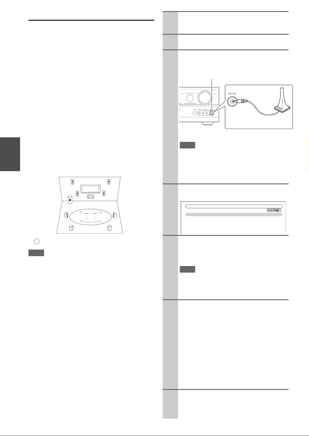
Using Audyssey 2EQ
®
Using Audyssey 2EQ to create a listening environment in
your home theater that all listeners will enjoy,
Audyssey 2EQ takes measurements at up to 3 positions
within the listening area. Position the microphone at ear
height of a seated listener with the microphone tip pointed
directly at the ceiling using a tripod. Do not hold the
microphone in your hand during measurements as this will
produce inaccurate results.
a First measurement position
Also referred to as the Main Listening Position this
refers to the most central position where one would
normally sit within the listening environment. 2EQ
uses the measurements from this position to calculate
speaker distance, level, polarity, and the optimum
crossover value for the subwoofer.
b Second measurement position
The right side of the listening area.
c Third measurement position
The left side of the listening area.
The distances from position a to b and a to c must be
at least 1 meter.
Turn on the AV receiver and the connected TV.
1
On the TV, select the input to which the AV
receiver is connected.
On the SKW-980 Subwoofer, set the OUTPUT
2
LEVEL control to “THX POSITION”.
Set the speaker setup microphone at the Main
3
Listening Position a, and connect it to the
SETUP MIC jack.
SETUP MIC jack
Speaker setup microphone
The speaker setting menu appears.
Note
• The on-screen setup menus appear only on a TV that is
connected to the HDMI OUT. If your TV is connected
to the MONITOR OUT V or the COMPONENT
VIDEO OUT, use the AV receiver’s display when
changing settings.
TV
cab
: Listening area
Note
• Make the room as quiet as possible. Background noise and Radio
Frequency Interference (RFI) can disrupt the room measurements. Close windows, televisions, radios, air conditioners, fluorescent lights, home appliances, light dimmers, or other
devices. Turn off the cell phone (even if it is not in use) or place
it away from all audio electronics.
• The microphone picks up test tones which played through each
speaker as Audyssey 2EQ Room Correction and Speaker Setup
run.
• Audyssey 2EQ Room Correction and Speaker Setup cannot be
performed while a pair of headphones is connected.
En
a to c: Listening position
24
When you’ve finished making the settings, press
4
ENTER.
2EQ: Auto Setup
Speaker Terminal Assign
Front High/Zone2
SurrBack/Front High
If you use a powered subwoofer, adjust the sub-
5
woofer volume level to 75 dB.
Test tones are played through the subwoofer. Use
the volume control on the subwoofer.
Note
• If you set the subwoofer’s volume control to its maximum and the displayed level is lower than 75 dB, leave
the subwoofer’s volume control at its maximum and
press ENTER to proceed to the next step.
Press ENTER.
6
Audyssey 2EQ Room Correction and Speaker
Setup starts.
Test tones are played through each speaker as
Audyssey 2EQ Room Correction and Speaker
Setup runs. This process takes a few minutes.
Please refrain from talking during measurements
and do not stand between speakers and the microphone.
Do not disconnect the speaker setup microphone
during Audyssey 2EQ Room Correction and
Speaker Setup, unless you want to cancel the
setup.
Place the setup microphone at the next position,
7
and then press ENTER.
Audyssey 2EQ performs more measurements.
This takes a few minutes.
Front High
Surr Back
Page 25
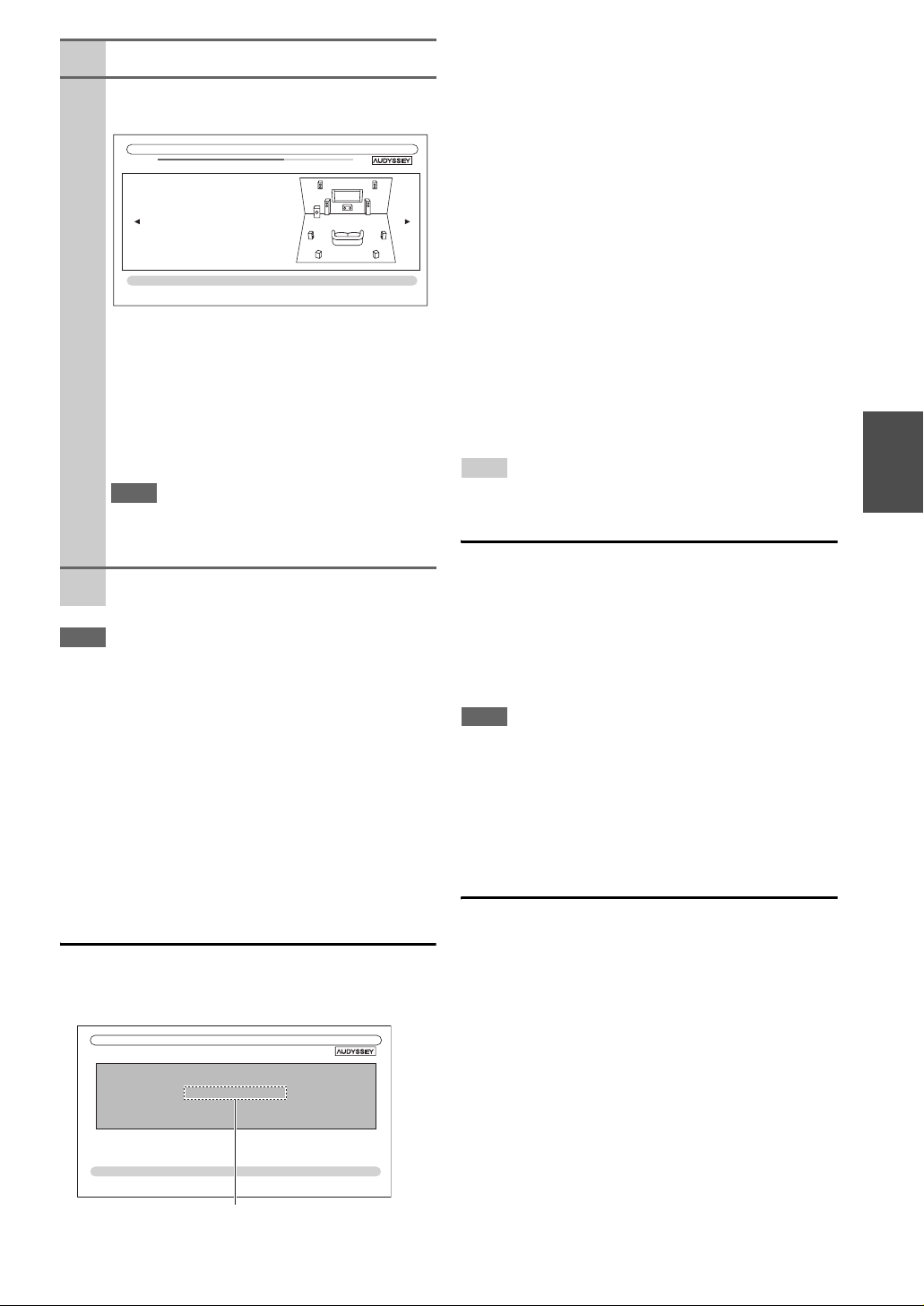
When prompted, repeat step 7.
8
Use q/w to select an option, and then press
9
ENTER.
2EQ: Auto Setup
Subwoofer Yes
Front 40Hz
Center 40Hz
Surround 100Hz
Front High 100Hz
Surr Back 120Hz
Surr Back Ch 2ch
Save
Cancel
- - Review Speaker Configuration - -
TV
The options are:
` Save:
Save the calculated settings and exit
®
Audyssey 2EQ
.
Setup
Room Correction and Speaker
` Cancel:
Cancel Audyssey 2EQ Room Correction and
Speaker Setup
Note
• You can view the calculated settings for the speaker
configuration, speaker distances, and speaker levels by
using e/r.
Disconnect the speaker setup microphone.
10
Note
• When Audyssey 2EQ Room Correction and Speaker Setup is
complete, the “Equalizer” will be set to “Audyssey” (➔ 40).
The Audyssey indicator will light (➔ 8).
• You can cancel Audyssey 2EQ Room Correction and Speaker
Setup at any point in this procedure simply by disconnecting the
setup microphone.
• Do not connect or disconnect any speakers during
Audyssey 2EQ Room Correction and Speaker Setup.
• If the AV receiver is muted, it will be unmuted automatically
when Audyssey 2EQ Room Correction and Speaker Setup starts.
• Changes to the room after Audyssey 2EQ Room Correction and
Speaker Setup requires you run Audyssey 2EQ Room Correction and Speaker Setup again, as room EQ characteristics may
have changed.
.
Error Messages
While Audyssey 2EQ Room Correction and Speaker
Setup is in progress, one of the error messages below may
appear.
2EQ: Auto Setup
Ambient noise is too high.
The options are:
` Retry:
Try again.
` Cancel:
Cancel Audyssey 2EQ Room Correction and
Speaker Setup.
• Ambient noise is too high.
The background noise is too loud. Remove the source of
the noise and try again.
• Speaker Matching Error!
The number of speakers detected was different from
that of the first measurement. Check the speaker connection.
•Writing Error!
This message appears if saving fails. Try saving again.
If this message appears after 2 or 3 attempts, contact
your Onkyo dealer.
• Speaker Detect Error
This message appears if a speaker is not detected. “No”
means that no speaker was detected.
Tip
• See “Speaker Configuration” for appropriate settings (➔ 11).
Changing the Speaker Settings Manually
You can manually make changes to the settings found during Audyssey 2EQ Room Correction and Speaker Setup.
See also:
• “Speaker Configuration” (➔ 39)
• “Speaker Distance” (➔ 40)
• “Level Calibration” (➔ 40)
• “Equalizer Settings” (➔ 40)
Note
• Sometimes due to the electrical complexities of subwoofer and
the interaction with the room, THX recommends setting the level
and the distance of the subwoofer manually.
• Sometimes due to interaction with the room, you may notice
irregular results when setting the level and/or distance of the
main speakers. If this happens, THX recommends setting them
manually.
Using a Powered Subwoofer
If you’re using a powered subwoofer and it outputs very
low-frequency sound at a low volume level, it may not be
detected by Audyssey 2EQ Room Correction and Speaker
Setup.
If the “Subwoofer” appears on the “Review Speaker
Configuration” screen as “No”, increase the subwoofer’s
volume to the half-way point, set it to its highest crossover
frequency, and then try running Audyssey 2EQ Room
Correction and Speaker Setup again. Note that if the volume is set too high and the sound distorts, detection issues
may occur, so use an appropriate volume level.
Retry
Cancel
Error message
En
25
Page 26
Listening to the Radio
This section describes the procedure using the buttons on the front panel unless otherwise specified.
Using the Tuner
With the built-in tuner you can enjoy AM and FM radio
stations. You can store your favorite stations as presets for
quick selection.
You can change the frequency steps (➔ 49).
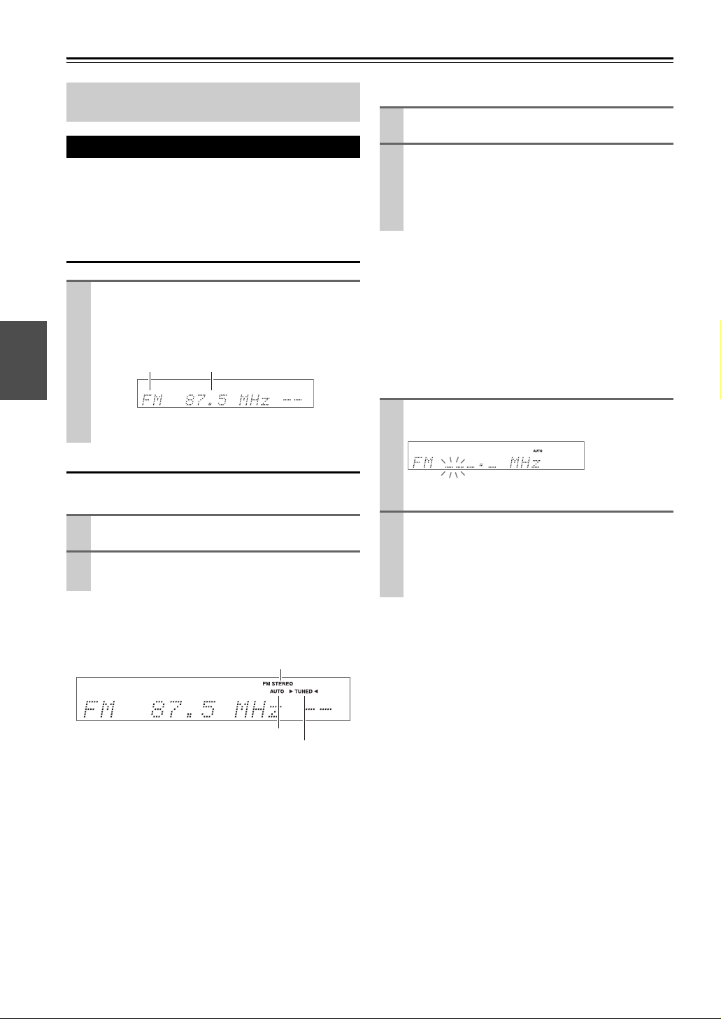
Listening to the Radio
Press TUNER to select either “AM” or “FM”.
In this example, FM has been selected.
Each time you press TUNER, the radio band
changes between AM and FM.
Band Frequency
(Actual display depends on the country.)
Tuning into Radio Stations
■ Manual tuning mode
Press TUNING MODE so that the AUTO indicator
1
goes off on the display.
Press and hold TUNING q/w.
2
The frequency stops changing when you release the
button.
Press the buttons repeatedly to change the frequency
one step at a time.
In manual tuning mode, FM stations will be in mono.
Tuning into weak FM stereo stations
If the signal from a stereo FM station is weak, it may be
impossible to get good reception. In this case, switch to
manual tuning mode and listen to the station in mono.
■ Tuning into stations by frequency
You can tune into AM and FM stations directly by entering the appropriate frequency.
On the remote controller, press TUNER repeat-
1
edly to select “AM” or “FM”, followed by D.TUN.
■ Auto tuning mode
Press TUNING MODE so that the AUTO indicator
1
lights on the display.
Press TUNING q/w.
2
Searching stops when a station is found.
When tuned into a station, the TUNED indicator lights.
When tuned into a stereo FM station, the FM STEREO
indicator lights on the display, as shown.
FM STEREO
AUTO
TUNED
(Actual display depends on the country.)
Within 8 seconds, use the number buttons to enter
2
the frequency of the radio station.
For example, to tune to 87.50 (FM), press 8, 7, 5, 0.
If you have entered the wrong number, you can retry
after 8 seconds.
En
26
Page 27

Presetting FM/AM Stations
Using RDS (European models)
You can store a combination of up to 40 of your favorite
FM/AM radio stations as presets.
Tune into the FM/AM station that you want to
1
store as a preset.
See the previous section.
Press MEMORY.
2
The preset number flashes.
While the preset number is flashing (about 8 sec-
3
onds), use PRESET e/r to select a preset from 1
through 40.
Press MEMORY again to store the station or chan-
4
nel.
The station or channel is stored and the preset number stops flashing.
Repeat this procedure for all of your favorite FM/
AM radio stations.
Note
• You can name your radio presets for easy identification (➔ 45).
Its name is displayed instead of the band and frequency.
Selecting Presets
To select a preset, use PRESET e/r on the AV
receiver, or the remote controller’s CH +/–.
Tip
• You can also use the remote controller’s number buttons to select
a preset directly.
Deleting Presets
RDS works only in areas where RDS broadcasts are
available.
When tuned into an RDS station, the RDS indicator lights.
What is RDS?
RDS stands for Radio Data System and is a method of
transmitting data in FM radio signals. It was developed by
the European Broadcasting Union (EBU) and is available
in most European countries. Many FM stations use it these
days. In addition to displaying text information, RDS can
also help you find radio stations by type (e.g., news, sport,
rock, etc.).
The AV receiver supports four types of RDS information:
■ PS (Program Service)
When tuned to an RDS station that’s broadcasting PS
information, the station’s name will be displayed. Pressing DISPLAY will display the frequency for 3 seconds.
■ RT (Radio Text)
When tuned to an RDS station that’s broadcasting text
information, the text will be shown on the display as
described in the next section.
■ PTY (Program Type)
This allows you to search for RDS radio stations by type
(➔ 28).
■ TP (Traffic Program)
This allows you to search for RDS radio stations that
broadcast traffic information (➔ 28).
Note
• In some cases, the text characters displayed on the AV receiver
may not be identical to those broadcast by the radio station. Also,
unexpected characters may be displayed when unsupported
characters are received. This is not a malfunction.
• If the signal from an RDS station is weak, RDS data may be
displayed intermittently or not at all.
Select the preset that you want to delete.
1
See the previous section.
While holding down MEMORY, press TUNING
2
MODE.
The preset is deleted and its number disappears from
the display.
When tuned to an RDS station that’s broadcasting text
information, the text can be displayed.
Displaying Radio Text (RT)
Press RT/PTY/TP once.
The RT information scrolls across the display.
Note
• The message “Waiting” may appear while the AV receiver waits
for the RT information.
• If the message “No Text Data” appears on the display, no RT
information is available.
En
27
Page 28

Finding Stations by Type (PTY)
■ RDS program types (PTY)
You can search for radio stations by type.
Press RT/PTY/TP twice.
1
The current program type appears on the display.
Use PRESET e/r to select the type of program
2
you want.
See the table shown later in this chapter.
To start the search, press ENTER.
3
The AV receiver searches until it finds a station of
the type you specified, at which point it stops briefly
before continuing with the search.
When a station you want to listen to is found, press
4
ENTER.
If no stations are found, the message “Not Found”
appears.
Listening to Traffic News (TP)
You can search for stations that broadcast traffic news.
Press RT/PTY/TP three times.
1
If the current radio station is broadcasting TP (Traffic Program), “[TP]” will appear on the display, and
traffic news will be heard as and when it’s broadcast.
If “TP” without square brackets appears, this means
that the station is not broadcasting TP.
To locate a station that is broadcasting TP, press
2
ENTER.
The AV receiver searches until it finds a station that’s
broadcasting TP.
If no stations are found, the message “Not Found”
appears.
Type Display
None None
News reports News
Current affairs Affairs
Information Info
Sport Sport
Education Educate
Drama Drama
Culture Culture
Science and technology Science
Va r ie d Va r ie d
Pop music Pop M
Rock music Rock M
Middle of the road music Easy M
Light classics Light M
Serious classics Classics
Other music Other M
Weather Weather
Finance Finance
Children’s programmes Children
Social affairs Social
Religion Religion
Phone in Phone In
Travel Travel
Leisure Leisure
Jazz music Jazz
Country music Country
National music Nation M
Oldies music Oldies
Folk music Folk M
Documentary Document
Alarm test TEST
Alarm Alarm!
En
28
Page 29
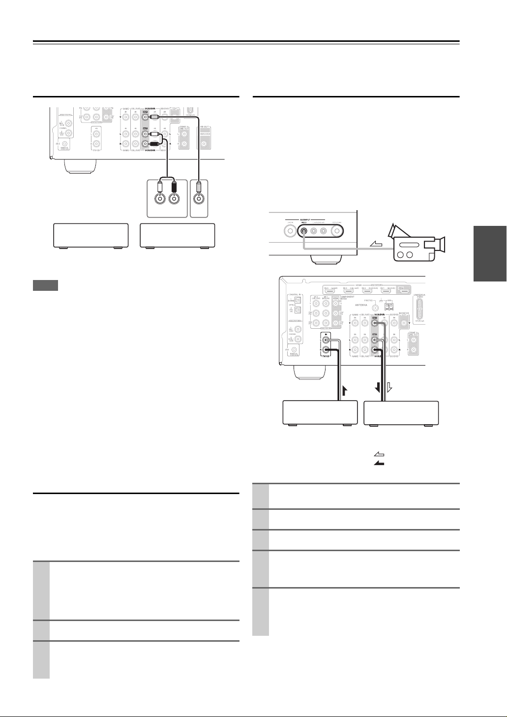
Recording
This section explains how to record the selected input source to a component with recording capability, and how to record
audio and video from different sources.
Connecting a Recording Component
L R
AUDIO
VCR,
DVD recorder
Note
• The AV receiver must be turned on for recording. Recording is
not possible while it’s in Standby mode.
• If you want to record directly from your TV or playback VCR to
the recording VCR without going through the AV receiver, connect the TV/VCR’s audio and video outputs directly to the
recording VCR’s audio and video inputs. See the manuals supplied with your TV and VCR for details.
• Video signals connected to composite video inputs can be
recorded only via composite video outputs. If your TV/VCR is
connected to a composite video input, the recording VCR must
be connected to a composite video output.
• The surround sound and DSP listening modes cannot be
recorded.
• Copy-protected Blu-ray Disc/DVDs cannot be recorded.
• Sources connected to a digital input cannot be recorded. Only
analog inputs can be recorded.
• DTS signals will be recorded as noise, so don’t attempt analog
recording of DTS CDs or LDs.
Cassette, CDR,
IN
MD, etc.
VIDEO
IN
Recording Separate AV Sources
Here you can record audio and video from completely
separate sources, allowing you to overdub audio onto your
video recordings. This function takes advantage of the fact
that when an audio-only input source (TV/CD) is selected,
the video input source remains unchanged.
In the following example, audio from the CD player connected to the TV/CD IN and video from the camcorder
connected to the AUX INPUT VIDEO jack are recorded
by the VCR connected to the VCR/DVR OUT jacks.
Camcorder
VCRCD player
: Video signal
: Audio signal
AV Recording
Audio sources can be recorded to a recorder (e.g., cassette
deck, CDR, MD) connected to the VCR/DVR OUT jacks.
Video sources can be recorded to a video recorder (e.g.,
VCR, DVD recorder) connected to the VCR/DVR OUT
jack.
Use the input selector buttons to select the source
1
that you want to record.
You can watch the source while recording. The AV
receiver’s MASTER VOLUME control has no effect
on recording.
On your recorder, start recording.
2
On the source component, start playback.
3
If you select another input source during recording,
that input source will be recorded.
Prepare the camcorder and CD player for play-
1
back.
Prepare the VCR for recording.
2
Press AUX input selector.
3
Press TV/CD input selector.
4
This selects the CD player as the audio source, but
leaves the camcorder as the video source.
Start recording on the VCR and start playback on
5
the camcorder and CD player.
The video from the camcorder and the audio from
the CD player are recorded by the VCR.
En
29
Page 30

Using the Listening Modes
Selecting Listening Modes
See “About Listening Modes” for detailed information about the listening modes (➔ 31).
Listening Mode Buttons
Press RECEIVER first.
MOVIE/TV, MUSIC, GAMETHX
MUSIC
MOVIE/TV
MOVIE/TV button
This button selects the listening modes intended for use
with movies and TV.
MUSIC button
This button selects the listening modes intended for use
with music.
GAME button
This button selects the listening modes intended for use
with video games.
STEREO button
This button selects Stereo and All Channel Stereo listening modes.
• The Dolby Digital and DTS listening modes can only be selected if your Blu-ray Disc/DVD player is connected to the AV
receiver with a digital audio connection (coaxial, optical, or HDMI).
• The listening modes you can select depends on the format of the input signal. To check the format, see “Displaying Source
Information” (➔ 21).
• While a pair of headphones is connected, you can select the following listening modes: Mono, Direct, and Stereo.
• The listening modes cannot be used while you are listening to sound through your TV speakers coming from components
connected to the AV receiver (“TV Sp On” appears on the front panel).
GAME
STEREO
THX button
This button selects the THX listening modes.
En
30
Page 31

About Listening Modes
The AV receiver’s listening modes can transform your listening room into a movie theater or concert hall, with high fidelity and stunning surround sound.
Explanatory Notes
SP LAYOUT
LISTENING MODE
■ Input Source
The following audio formats are supported by the listening mode.
A
S
This is mono (monophonic) sound.
This is stereo (stereophonic) sound. Two independent audio signal channels are reproduced through two
speakers.
D
This is 5.1-channel surround sound. This surround system has five main channels of sound and a sixth subwoofer channel (called the point-one channel).
F
This is 7.1-channel surround sound. This is a further sound enhancement to 5.1 channel sound with two
additional speakers that provide greater sound envelopment and more accurate positioning of sounds.
G
This is DTS-ES surround sound. This surround system can produce a discrete or a matrix-encoded sixth
channel from existing DTS 5.1 encoded material.
H
This is Dolby Digital EX surround sound. This provides a center back surround channel from 5.1-channel
sources.
ijab c
de
abFront speakers
c Center speaker
deSurround speakers
f Subwoofer
ghSurround back speakers
ijFront high speakers
f
gh
■ Speaker Layout
The illustration shows which speakers are activated in each channel. See “Speaker Configuration” for the speaker setup
(➔ 39).
X
C NZ
Press RECEIVER followed by SP LAYOUT
repeatedly to select the speakers you want to
use; front high or surround back.
En
31
Page 32

Listening Modes
Listening Mode Description Input
Direct In this mode, audio from the input source is output without surround-sound
Di rectdioPP
Stereo Sound is output by the front left and right speakers and subwoofer.
StereodioPP
Mono Use this mode when watching an old movie with a mono soundtrack, or use
Mo no eodi oPP
Multichannel This mode is for use with PCM multichannel sources.
MultichioPP
Dolby Pro Logic IIx
Dolby Pro Logic II
PL b Mo v i e PP
PL b Mu s i c PP
PL b GamecPP
PL x G Mo v i eP
PL x G MusicP
PL x G GamecP
Dolby Pro Logic IIz
Height
PL z G He i gh t
Dolby EX These modes expand 5.1-channel sources for 6.1/7.1-channel playback.
Do l by c EXoPP
Dolbyc D i EXP
processing. The “Sp Config” (presence of speakers), “Sp Distance” and
“A/V Sync” settings are enabled, but much of the processing set via AUDIO
is disabled. See “Advanced Setup” for more details (➔ 36).
it with the foreign language soundtracks recorded in the left and right channels of some movies. It can also be used with DVDs or other sources containing multiplexed audio, such as karaoke DVDs.
*2
Dolby Pro Logic IIx expands any 2-channel source for 7.1-channel playback. It provides a very natural and seamless surround-sound experience that
fully envelops the listener. As well as music and movies, video games can
also benefit from the dramatic spatial effects and vivid imaging. If you’re not
using any surround back speakers, Dolby Pro Logic II will be used instead
of Dolby Pro Logic IIx.
• Dolby PLIIx Movie
Use this mode with any stereo or Dolby Surround (Pro Logic) movie (e.g.,
TV, DVD, VHS).
• Dolby PLIIx Music
Use this mode with any stereo or Dolby Surround (Pro Logic) music source
(e.g., CD, radio, cassette, TV, VHS, DVD).
• Dolby PLIIx Game
Use this mode with video games, especially those that bear the Dolby Pro
Logic II logo.
• Dolby PLIIx Movie and Dolby PLIIx Music
These modes use the Dolby Pro Logic IIx modes to expand 5.1-channel
sources for 7.1-channel playback.
Dolby Pro Logic IIz Height is designed to more effectively use existing
program material when height channel speaker outputs are present. Dolby
Pro Logic IIz Height can be used to upmix a variety of sources from movies
and music, but are particularly well-suited to upmix game content.
They’re especially suited to Dolby EX soundtracks that include a matrixencoded surround back channel. The additional channel adds an extra dimension and provides an enveloping surround sound experience, perfect for
rotating and fly-by sound effects.
Source
A
S
D
F
G
H
A
S
D
F
G
H
DXCN
SXCN
DN
S
D
F
D
H
Speaker
Layout
ZXC
*1
N
ZXC
N
*3
N
*4
N
En
32
Page 33

Listening Mode Description Input
Source
Dolby Digital In this mode, audio from the input source is output without surround-sound
Dolbyc D ioPP
Dolby Digital Plus
processing. “Sp Config” (presence of speakers), “Crossover”, “Sp Distance”, “A/V Sync” and much of the processing set via AUDIO are enabled.
See “Advanced Setup” for more details (➔ 36).
*5
Do l by c D+oPP
Dolby TrueHD
DD lTeHDPPru
DTS
D XCN
D XCN
F XCN
D XCN
F XCN
D XCN
DTS ddi o P P
DTS-HD High
Resolution Audio
D XCN
F XCN
DTS–HD HR
DTS-HD Master
Audio
D XCN
F XCN
DTS–HD MSTR
DTS Express
DTS Ex p r e s s
*6
DSD
S
D
D XCN
DSD
DTS 96/24
*7
DTSee96/24PP
DTS-ES Discrete
ESS Discrete
This mode is for use with DTS 96/24 sources. This is high-resolution DTS
with a 96 kHz sampling rate and 24-bit resolution, providing superior fidelity. Use it with DVDs that bear the DTS 96/24 logo.
*8
This mode is for use with DTS-ES Discrete soundtracks, which use a discrete surround back channel for true 6.1/7.1-channel playback. The seven
totally separate audio channels provide better spatial imaging and 360-
D XCN
GN
degree sound localization, perfect for sounds that pan across the surround
channels. Use it with DVDs that bear the DTS-ES logo, especially those with
a DTS-ES Discrete soundtrack.
*8
DTS-ES Matrix
ESS Ma t r i x te
DTS Neo:6 This mode expands any 2-channel source for up to 7.1-channel playback. It
Neo : 6 trixte
This mode is for use with DTS-ES Matrix soundtracks, which use a matrixencoded back-channel for 6.1/7.1-channel playback. Use it with DVDs that
bear the DTS-ES logo, especially those with a DTS-ES Matrix soundtrack.
uses seven full-bandwidth channels of matrix decoding for matrix-encoded
material, providing a very natural and seamless surround sound experience
GN
S XCN
that fully envelops the listener.
Neo : 6 trixteNeo : 6C i nema
•Neo:6 Cinema
Use this mode with any stereo movie (e.g., TV, DVD, VHS).
Neo : 6 t Mu s i c
•Neo:6 Music
Use this mode with any stereo music source (e.g., CD, radio, cassette, TV,
VHS, DVD).
This mode uses Neo:6 to expand 5.1-channel sources for 6.1/7.1-channel
DN
playback.
Speaker
Layout
*1
*1
*1
*1
XCN
*4
*4
*4
*4
En
33
Page 34

Listening Mode Description Input
THX Founded by George Lucas, THX develops stringent standards that ensure
THXe Ci nemaP
THXe Mu s i c aP
THXe Game s aP
THX I / S C i n
THX I / S Mus
THX I / S Gam
THXe Sur r a EX
movies are reproduced in movie theaters and home theaters just as the director intended. THX Modes carefully optimize the tonal and spatial characteristics of the soundtrack for reproduction in the home-theater environment.
They can be used with 2-channel matrixed and multichannel sources. Surround back speaker output depends on the source material and the selected
listening mode.
•THX Cinema
THX Cinema mode corrects theatrical soundtracks for playback in a home
theater environment. In this mode, THX Loudness Plus is configured for
cinema levels and Re-EQ, Timbre Matching, and Adaptive Decorrelation
are active.
•THX Music
THX Music mode is tailored for listening to music, which is typically mastered at significantly higher levels than movies. In this mode, THX Loudness Plus is configured for music playback and only Timbre Matching is
active.
• THX Games
THX Games mode is meant for spatially accurate playback of game audio,
which is often mixed similarly to movies but in a smaller environment. THX
Loudness Plus is configured for game audio levels, with Timbre Matching
active.
*2
The combination of Dolby Pro Logic II/IIx
Games modes can be used.
The combination of Dolby Pro Logic IIz Height
Music/Games modes can be used.
The combination of DTS Neo:6 and THX Cinema/Music/Games modes
can be used.
• THX I/S Cinema
This mode expands Dolby Digital and DTS 5.1-channel sources for 7.1channel playback. It does this by analyzing the composition of the surround
source, optimizing the ambient and directional sounds to produce the surround back channel output. This is a new and improved mode especially for
integrated home theater systems.
• THX I/S Music
This mode is designed for use with music. It expands Dolby Digital and
DTS 5.1-channel sources for 7.1-channel playback.
•THX I/S Games
This mode is designed for use with video games.
• THX Surround EX
This mode expands 5.1-channel sources for 6.1/7.1- channel playback. It’s
especially suited to Dolby Digital EX sources. THX Surround EX, also
known as Dolby Digital Surround EX, is a joint development between
Dolby Laboratories and THX Ltd.
and THX Cinema/Music/
*3
and THX Cinema/
Source
D
F
G
S
D
H
S
D
F
G
H
S
D
F
H
D
F
Speaker
Layout
CN
CN
N
CN
N
En
34
Page 35

Onkyo-Original DSP Listening Modes
Listening Mode Description Input
Source
Orchestra Suitable for classical or operatic music, this mode emphasizes the surround
Orches t ra
channels in order to widen the stereo image, and simulates the natural reverberation of a large hall.
Unplugged Suitable for acoustic instruments, vocals, and jazz, this mode emphasizes the
Unpl ugged
front stereo image, giving the impression of being right in front of the stage.
A
S
D
G
H
Studio-Mix Suitable for rock or pop music, listening to music in this mode creates a
Studio–Mix
lively sound field with a powerful acoustic image, like being at a club or rock
concert.
TV Logic This mode adds realistic acoustics to TV shows produced in a TV studio,
TV Lo g i c
surround effects to the entire sound, and clarity to voices.
Game-RPG Use this mode when playing role playing game discs.
Game –RPG
Game-Action Use this mode when playing action game discs.
Game –A c t i o n
Game-Rock Use this mode when playing rock game discs.
Game –Ro c k
Game-Sports Use this mode when playing sports game discs.
Game –S po r t s
All Ch Stereo Ideal for background music, this mode fills the entire listening area with ste-
Al l Ch St
reo sound from the front, surround, and surround back speakers.
Full Mono In this mode, all speakers output the same sound in mono, so the sound you
Fu l l Mono
T-D ( Th ea te rDimensional)
T–D
hear is the same regardless of where you are within the listening room.
With this mode you can enjoy a virtual surround sound even with only two or
three speakers. This works by controlling how sounds reach the listener’s left
and right ears. Good results may not be possible if there’s too much reverb,
so we recommend that you use this mode in an environment with little or no
A
S
D
F
G
H
natural reverb.
Speaker
Layout
CN
*9
XCN
ZXC
N
*9
Note
*1
Based on the audio channels contained in the source, the corresponding speakers will output the sound.
*2
If Powered Zone 2 is being used, Dolby Pro Logic II is used.
*3
Surround back speakers are not supported.
*4
Front high speakers are not supported.
*5
For the Blu-ray Discs, Dolby Digital is used in a 3.1/5.1-channel speaker system.
*6
AV receiver can input the DSD signal from HDMI IN. Setting the output setting on the player side to PCM might obtain a better
sound according to the player. In that case, set the output setting on the player side to PCM.
*7
DTS is used depending on the configuration of the AV receiver (e.g., Audyssey Dynamic EQ® is on or Powered Zone 2 is being
used).
*8
If there are no surround back speakers or Powered Zone 2 is being used, DTS is used.
*9
Output can be switched between front high or surround back speakers by pressing SP LAYOUT [depending on the “Speaker Con-
figuration” setting (➔ 39)].
• The listening modes cannot be selected with some source formats.
En
35
Page 36

Advanced Operations
Advanced Setup
On-screen Setup Menus
The on-screen setup menus appear only on a TV that
is connected to the HDMI OUT. If your TV is connected to the composite video MONITOR OUT or the
COMPONENT VIDEO OUT, use the AV receiver’s
display when changing settings.
This manual describes the procedure using the
remote controller unless otherwise specified.
MENU
1. Input/Output Assign
a
2. Speaker Setup
b
3. Audio Adjust
c
4. Source Setup
d
5. Listening Mode Preset
e
6. Miscellaneous
f
7. Hardware Setup
g
8. Remote Controller Setup
h
9. Lock Setup
i
a Input/Output Assign
(➔ 37)
1. Input/Output Assign
1. Monitor Out
2. HDMI Input
3. Component Video Input
4. Digital Audio Input
b Speaker Setup
(➔ 39)
2. Speaker Setup
1. Speaker Settings
2. Speaker Configuration
3. Speaker Distance
4. Level Calibration
5. Equalizer Settings
6. THX Audio Setup
c Audio Adjust
(➔ 42)
3. Audio Adjust
1. Multiplex/Mono
2. Dolby
3. DTS
4. Theater-Dimensional
5. LFE Level
d Source Setup (➔ 43) i Lock Setup (➔ 50)
4. Source Setup
1. Audyssey
2. IntelliVolume
3. A/V Sync
4. Name Edit
5. Picture Adjust
e Listening Mode Preset
(➔ 47)
f Miscellaneous
(➔ 48)
6. Miscellaneous
1. Volume Setup
2. OSD Setup
g Hardware Setup
(➔ 49)
7. Hardware Setup
1. Remote ID
2. Tuner
3. HDMI
h Remote Controller
Setup (➔ 60)
8. Remote Controller Setup
1. Remote Mode Setup
9. Lock Setup
Setup
Common Procedures in Setup Menu
Remote indicator
RECEIVER
ENTER
q/w/e/r
SETUP
The on-screen setup menus appear on the connected TV
and provide a convenient way to change the AV receiver’s
various settings. Settings are organized into nine categories on the main menu.
Carry out the settings by using the on-screen display.
Press RECEIVER followed by SETUP.
1
The following menu appears.
MENU
1. Input/Output Assign
2. Speaker Setup
3. Audio Adjust
4. Source Setup
5. Listening Mode Preset
6. Miscellaneous
7. Hardware Setup
8. Remote Controller Setup
9. Lock Setup
Tip
• If the main menu doesn’t appear, make sure the appropriate external input is selected on your TV.
Use q/w to select a menu, and then press ENTER.
2
Use q/w to select target and then press ENTER.
3
Use q/w to select option and e/r to change the
4
setting.
Press SETUP to close the menu.
Press RETURN to return to the main menu.
Note
• This procedure can also be performed on the AV receiver by
using SETUP, arrow buttons, and ENTER.
• During Audyssey 2EQ
messages, etc., that are displayed on the TV screen will appear
in the Display.
®
Room Correction and Speaker Setup,
RETURN
En
36
5. Listening Mode Preset
1. BD/DVD
2. VCR/DVR
3. CBL/SAT
4. GAME
5. AUX
6. TUNER
7. TV/CD
8. PORT
Page 37

Explanatory Notes
a
b
c
Main Menu Speaker Setup
Subwoofer
Ye s
:
Select if a subwoofer is connected.
No:
Select if no subwoofer is connected.
a Menu selection
b Setting target
c Setting options (default setting underlined)
Input/Output Assign
Main Menu Input/Output Assign
Monitor Out
You can specify the output resolution for the HDMI OUT
and COMPONENT VIDEO MONITOR OUT and have
the AV receiver upconvert the picture resolution as necessary to match the resolution supported by your TV.
■ Resolution
` Through
` Auto:
` 480p (480p/576p):
` 720p:
` 1080i:
` 1080p:
HDMI Input
If you connect a video component to an HDMI input, you
must assign that input to an input selector. For example, if
you connect your Blu-ray Disc/DVD player to HDMI
IN 2, you must assign “HDMI2” to the “BD/DVD” input
selector.
If you’ve connected your TV to the AV receiver with an
HDMI cable, composite video and component video
sources can be upconverted* to HDMI. See “Video Connection Formats” for more information on video signal
flow and upconversion (➔ 18).
:
Select this to pass video through the AV receiver at
the same resolution and with no conversion.
Select this to have the AV receiver automatically
convert video at resolutions not supported by your
TV.
Select this for 480p or 576p output and video conversion as necessary.
Select this for 720p output and video conversion as
necessary.
Select this for 1080i output and video conversion as
necessary.
Select this for 1080p output and video conversion as
necessary.
Composite video,
component video
IN
OUT
Composite video,
component video
HDMI
HDMI
Here are the default assignments.
Input selector Default assignment
BD/DVD HDMI1
VCR/DVR HDMI2
CBL/SAT HDMI3
GAME HDMI4
AUX ----TUNER ----- (Fixed)
TV/CD ----PORT -----
■ BD/DVD, VCR/DVR, CBL/SAT, GAME, AUX,
TV/CD, PORT
` HDMI1, HDMI2, HDMI3, HDMI4:
Select a corresponding HDMI input that the video
component has been connected.
` -----:
Select this to output composite video and component
video sources from the HDMI OUT. The video signal from HDMI output is configured in “Component
Video Input” (➔ 38).
• Each HDMI input cannot be assigned to two input selec-
tors or more. When HDMI1 - HDMI4 have already
been assigned, you must set first any unused input selectors to “-----” or you will be unable to assign HDMI1
- HDMI4 to input selector.
Note
• When an HDMI IN is assigned to an input selector as explained
here, the same HDMI IN will be set as a priority in the “Digital
Audio Input” (➔ 38). In this case, if you want to use the coaxial
or optical audio input, make the selection in the Audio Selector
in the Audio menu (➔ 22).
• TUNER selector cannot be assigned and is fixed at the “-----”
option.
• If you connect a component (such as UP-A1 Dock that seated
iPod) to UNIVERSAL PORT jack, you cannot assign any input
to PORT selector.
• Do not assign the component connected with the HDMI input to
TV/CD selector when you set “TV Control” setting to “On”
(➔ 50). Otherwise, appropriate CEC (Consumer Electronics
Control) operation will not be guaranteed.
En
37
Page 38

Component Video Input
Digital Audio Input
If you connect a video component to a component video
input, you must assign that input to an input selector. For
example, if you connect your Blu-ray Disc/DVD player to
COMPONENT VIDEO IN 2, you must assign “IN2” to
the “BD/DVD” input selector.
Here are the default assignments.
Input selector Default assignment
BD/DVD IN1
VCR/DVR ----CBL/SAT IN2
GAME ----AUX ----TUNER ----- (Fixed)
TV/CD ----PORT -----
■ BD/DVD, VCR/DVR, CBL/SAT, GAME, AUX,
TV/CD, PORT
` IN1, IN2:
Select a corresponding component video input that
the video component has been connected.
` -----:
Select if you are using HDMI output, not component
video output, to output composite video and component video sources.
Note
• If you connect a component (such as UP-A1 Dock that seated
iPod) to the UNIVERSAL PORT jack, you cannot assign any
input to PORT selector.
If you connect a component to a digital audio input, you
must assign that input to an input selector. For example, if
you connect your CD player to the OPTICAL IN 1, you
must assign “OPT1” to the “TV/CD” input selector.
Here are the default assignments.
Input selector Default assignment
BD/DVD COAX1
VCR/DVR - ---CBL/SAT COAX2
GAME OPT1
AUX ----TUNER ----- (Fixed)
TV/CD OPT2
PORT -----
■ BD/DVD, VCR/DVR, CBL/SAT, GAME, AUX,
TV/CD, PORT
` COAX1, COAX2, OPT1, OPT2:
Select a corresponding digital audio input that the
component has been connected.
` -----:
Select if the component is connected to an analog
audio input.
Note
•When an HDMI IN is assigned to an input selector in “HDMI
Input” (➔ 37), the same HDMI IN will be set as a priority in this
assignment. In this case, if you want to use the coaxial or optical
audio input, make the selection in the Audio Selector in the
Audio menu.
• Available sampling rate for PCM signals from a digital input
(optical and coaxial) is 32/44.1/48/88.2/96 kHz/16, 20, 24 bit.
• If you connect a component (such as UP-A1 Dock that seated
iPod) to the UNIVERSAL PORT jack, you cannot assign any
input to PORT selector.
En
38
Page 39

Speaker Setup
Speaker Configuration
Main menu Speaker Setup
Some of the settings in this section are set automatically
by Audyssey 2EQ® Room Correction and Speaker
Setup function (➔ 23).
Here you can check the settings made by Audyssey 2EQ
Room Correction and Speaker Setup function, or set them
manually, which is useful if you change one of the connected speakers after using Audyssey 2EQ Room Correction and Speaker Setup function.
Note
These settings are disabled when:
• a pair of headphones is connected, or
•the “Audio TV Out” setting is set to “On” (➔ 49) and an input
selector other than HDMI is selected.
Speaker Settings
If you change these settings, you must run
Audyssey 2EQ Room Correction and Speaker Setup
again (➔ 23).
■ Speaker Terminal Assign
Front High/Zone2
With this setting, you can specify the speakers connected to FRONT HIGH OR ZONE 2 SPEAKERS
terminals.
` Front High
Front high speakers can be used.
` Zone2:
Zone 2 speakers can be used. (Powered Zone 2
enabled).
SurrBack/Front High
With this setting, you can specify the speakers connected to SURR BACK OR FRONT HIGH SPEAK-
ERS terminals.
` Surr Back
Surround back speakers can be used.
` Front High:
Front high speakers can be used.
Note
•If “Front High” is selected in the “Front High/Zone2” setting,
you cannot select “Front High” here.
:
:
Speaker configuration settings only need to be
changed if you are not using all of the speakers in this
package.
■ Subwoofer, Center, Surround
` Ye s
:
Select if a subwoofer/speaker(s) is connected.
` No:
Select if no subwoofer/speaker is connected.
■ Front High
*1*2*3
` Ye s :
Select if a speaker(s) is connected.
` No:
Select if no speaker is connected.
■ Surr Back
*1*2*4
` Ye s :
Select if a speaker(s) is connected.
` No:
Select if no speaker is connected.
Note
*1
If the “Surround” setting is set to “No”, this setting cannot be
selected.
*2
If Powered Zone 2 is being used (➔ 54), this setting cannot be
selected.
*3
If you have selected other than “Front High” in the “Front
High/Zone2” or “SurrBack/Front High” setting, this setting
cannot be selected.
*4
If you have selected other than “Surr Back” in the “SurrBack/Front High” setting, this setting cannot be selected.
■ Surr Back Ch
` 1ch:
Select if only one surround back speaker L is connected.
` 2ch
:
Select if two (left and right) surround back speakers
are connected.
Note
• If the “Surr Back” setting is set to “No” (➔ 39), this setting
cannot be selected.
En
39
Page 40

Speaker Distance
This setting is set automatically by Audyssey 2EQ®
Room Correction and Speaker Setup function (➔ 23).
Here you can specify the distance from each speaker to the
listening position so that the sound from each speaker
arrives at the listener’s ears as the sound designer
intended.
■ Unit
` feet:
Distances can be set in feet. Range: 1ft to 30ft in
1 foot steps.
` meters:
Distances can be set in meters. Range: 0.3m to 9.0m
in 0.3 meter steps.
(The default setting varies from country to country.)
■ Left, Front High Left, Center, Front High Right,
Right, Surr Right, Surr Back Right, Surr Back
Left, Surr Left, Subwoofer
` Specify the distance from the each speaker to your lis-
tening position.
Note
• Speakers that you set to “No” in the “Speaker Configuration”
cannot be selected (➔ 39).
Level Calibration
This setting is set automatically by Audyssey 2EQ
Room Correction and Speaker Setup function (➔ 23).
Adjust the level control of the subwoofer to the “THX”
position before calibrating this system.
Tip
• If you’re using a handheld sound level meter, adjust the level of
each speaker so that it reads 75 dB SPL at the listening position,
measured with C-weighting and slow reading.
Equalizer Settings
This setting is set automatically by Audyssey 2EQ
Room Correction and Speaker Setup function (➔ 23).
With the Equalizer settings, you can adjust the tone of
speakers individually with a 5-band equalizer. The volume
of each speaker can be set (➔ 40).
■ Equalizer
` Manual:
You can adjust the equalizer for each speaker manually. If you selected “Manual”, continue with this
procedure.
Press w to select “Channel”, and then use e/
1
r to select a speaker.
Use q/w to select a frequency, and then use
2
the e/r to adjust the level at that frequency.
The volume at each frequency can be adjusted
from –6dB to 0dB
Tip
• Low frequencies (e.g., 63Hz) affect bass sounds;
high frequencies (e.g., 16000Hz) affect treble
sounds.
Use q to select “Channel”, and then use e/r
3
to select another speaker.
Repeat steps 1 and 2 for each speaker.
You cannot select speakers that you set to “No”
in the “Speaker Configuration” (➔ 39).
to +6dB in 1 dB steps.
Here you can adjust the level of each speaker with the
built-in test tone so that the volume of each speaker is the
same at the listening position.
*1
■ Left, Front High Left, Center
, Front High Right,
Right, Surr Right, Surr Back Right, Surr Back
Left, Surr Left
` –12dB to 0dB to +12dB in 1 dB step.
■ Subwoofer
*1
` –15dB to 0dB to +12dB in 1 dB step.
Note
• Speakers that you set to “No” in the “Speaker Configuration”
cannot be selected (➔ 39).
• Speakers that you set to “No” in the “Speaker Configuration” do
not output the test tone (➔ 39).
• The speakers cannot be calibrated while the AV receiver is
muted.
• The test tone is output at the standard level for THX, which is
0 dB (absolute volume setting 82). If you normally listen at volume settings below this, be careful because the test tone will be
much louder.
*1
For the center speaker and subwoofer, the level settings made
by using the Audio menu are saved (➔ 22).
En
40
` Audyssey:
This is selected automatically by Audyssey 2EQ
Room Correction and Speaker Setup function. The
Audyssey Dynamic Volume indicator will light
(➔ 8) and “Dynamic EQ” and “Dynamic Volume”
become available (➔ 43).
:
` Off
No Audyssey 2EQ equalizing will apply.
Note
• The front, center, surround, and surround back speakers can be
adjusted at 63Hz, 250Hz, 1000Hz, 4000Hz, and 16000Hz. The
subwoofer can be adjusted at 25Hz, 40Hz, 63Hz, 100Hz, and
160Hz.
• While the Direct listening mode is selected, the equalizer settings have no effect.
• Audyssey equalizing does not work for DSD sources.
Page 41

THX Audio Setup
This setting is NOT set automatically by
Audyssey 2EQ® Room Correction and Speaker Setup
function (➔ 23).
With the “SurrBack Speaker Spacing” setting, you can
specify the distance between your surround back speakers.
You can then apply THX’s Boundary Gain Compensation
(BGC) to compensate the perceived exaggeration of low
frequencies for listeners sitting very close to a room
boundary (i.e., wall).
You can also set the THX Loudness Plus. When the
“Loudness Plus” is set to “On”, it is possible to enjoy
even subtle nuances of audio expression at low volume.
This result is only available when the THX listening mode
is selected.
■ SurrBack Speaker Spacing
` < 1ft (< 0.3m):
Select this if your surround back speakers are
between 0 and 1 foot (0–30 cm) apart.
` 1 ft - 4 ft (0.3 m - 1.2 m):
Select this if your surround back speakers are
between 1 and 4 feet (0.3–1.2 m) apart.
` > 4ft (> 1.2m):
Select this if your surround back speakers are more
than 4 feet (1.2 m) apart.
Note
• Cannot be set if “Surr Back Ch” is set to “1ch” (➔ 39), “Surr
Back” is set to “No” (➔ 39), or Powered Zone 2 is being used
(➔ 54).
■ BGC
` Off
:
Select this to turn off BGC.
` On:
Select this to turn on BGC.
■ Loudness Plus
` Off:
Select this to turn off Loudness Plus.
` On
:
Select this to turn on Loudness Plus.
■ Preserve THX Settings
:
` Ye s
Audyssey Dynamic EQ® /
Audyssey Dynamic Volume® will not be active in
THX listening mode.
` No:
Audyssey Dynamic EQ /
Audyssey Dynamic Volume will be active in THX
listening mode depending on the setting.
Note
• This setting is fixed at “Yes ” if “Loudness Plus” is set to “On”.
THX Loudness Plus
THX Loudness Plus is a new volume control technology
featured in THX Ultra2 Plus™ and THX Select2 Plus™
Certified receivers. With THX Loudness Plus, home
theater audiences can now experience the rich details in
a surround mix at any volume level. A consequence of
turning the volume below Reference Level is that certain sound elements can be lost or perceived differently
by the listener. THX Loudness Plus compensates for the
tonal and spatial shifts that occur when the volume is
reduced by intelligently adjusting ambient surround
channel levels and frequency response. This enables
users experience the true impact of soundtracks regardless of the volume setting. THX Loudness Plus is automatically applied when listening in any THX listening
mode. The new THX Cinema, THX Music, and THX
Games modes are tailored to apply the proper THX
Loudness Plus settings for each type of content.
En
41
Page 42

Audio Adjust
Main menu Audio Adjust
With the Audio Adjust functions and settings, you can
adjust the sound and listening modes as you like.
Multiplex/Mono
■ Multiplex
This setting determines which channel of a stereo multiplex source is output. Use it to select audio channels or
languages with multiplex sources, multilingual TV
broadcasts, and so on.
Input Channel
` Main
:
The main channel is output.
` Sub:
The sub channel is output.
` Main/Sub:
Both the main and sub channels are output.
■ Mono
This setting specifies the channel to be used for playing
any 2-channel digital source such as Dolby Digital, or
2-channel analog/PCM source in the Mono listening
mode.
Input Channel
` Left + Right
Both the left and right channels are output.
` Left:
Only the left channel is output.
` Right:
Only the right channel is output.
Output Speaker
` Center
Mono audio is output by the center speaker.
` Left / Right:
Mono audio is output by the front left and right
speakers.
This setting determines which speakers output mono
audio when the Mono listening mode is selected.
Note
•If the “Center” setting is set to “No” (➔ 39), this setting is fixed
at “Left / Right”.
:
:
Dolby
■ PLIIx Music (2ch Input)
These settings apply to only 2-channel stereo sources.
If you’re not using any surround back speakers, these
settings apply to Dolby Pro Logic II, not Dolby Pro
Logic IIx.
Panorama
` On:
Panorama function on.
` Off
:
Panorama function off.
En
42
With this setting, you can broaden the width of the front
stereo image when using the Dolby Pro Logic IIx Music
listening mode.
Dimension
` –3 to 0 to +3
With this setting, you can move the sound field forward
or backward when using the Dolby Pro Logic IIx Music
listening mode. Higher settings move the sound field
backward. Lower settings move it forward.
If the stereo image feels too wide, or there’s too much
surround sound, move the sound field forward to
improve the balance. Conversely, if the stereo image
feels like it’s in mono, or there’s not enough surround
sound, move it backward.
Center Width
` 0 to 3
to 7
With this setting, you can adjust the width of the sound
from the center speaker when using the Dolby Pro
Logic IIx Music listening mode. Normally, if you’re
using a center speaker, the center channel sound is output by only the center speaker. (If you’re not using a
center speaker, the center channel sound will be distributed to the front left and right speakers to create a phantom center). This setting controls the front left, right,
and center mix, allowing you to adjust the weight of the
center channel sound.
■ PLIIz Height Gain
The Height Gain Control in Dolby Pro Logic IIz
enables the listener to select how much gain is applied
to the front high speakers. There are three settings,
“Low”, “Mid” and “High”, and the front high speakers
are accentuated in that order. While “Mid” is the default
listening setting, the listener may adjust the Height Gain
Control to their personal preference.
` Low:
Low PLIIz Height Gain becomes active.
:
` Mid
Medium PLIIz Height Gain becomes active.
` High:
High PLIIz Height Gain becomes active.
Note
•If the “Front High” settings is set to “No” (➔ 39), this setting
cannot be selected.
■ Dolby EX
This setting determines how Dolby EX encoded signals
are handled. This setting is unavailable if no surround
back speakers are connected. This setting is effective
with Dolby Digital, Dolby Digital Plus and Dolby
TrueHD only.
Dolby EX
` Auto :
If the source signal contains a Dolby EX flag, the
Dolby EX or THX Surround EX listening mode is
used.
` Manual
:
You can select any available listening mode.
Page 43

Note
•If the “Surr Back” setting is set to “No” (➔ 39), this setting
cannot be selected.
•If the “Front High” setting is enabled (➔ 39), this setting is
fixed at “Manual”.
DTS
Source Setup
Items can be set individually for each input selector.
Preparation
Press the input selector buttons to select an input source.
■ Neo:6 Music
Center Image
` 0 to 2
to 5
The DTS Neo:6 Music listening mode creates 6-channel
surround sound from 2-channel stereo sources. With
this setting, you can specify by how much the front left
and right channel output is attenuated in order to create
the center channel.
Setting a value “0” in the middle is set to hear a sound.
Sound is spread in left and right (the outside) so that the
set value is made big. Please adjust by liking.
Theater-Dimensional
■ Listening Angle
` Wide
:
Select if the listening angle is 40 degrees.
` Narrow:
Select if the listening angle is 20 degrees.
With this setting, you can optimize the Theater-Dimensional listening mode by specifying the angle of the
front left and right speakers relative to the listening
position. Ideally, the front left and right speakers should
be equidistant from the listening position and at an
angle close to one of the two available settings.
Front left speaker Front right speaker
20°/40°
LFE Level
■ Dolby Digital*1, DTS*2, Multich PCM, Dolby
TrueHD, DTS-HD Master Audio, DSD
` –QdB, –20dB, –10dB, or 0dB
With these settings, you can set the level of the LFE (Low
Frequency Effects) channel individually for each input
sources.
If you find that low-frequency effects are too loud when
using one of these sources, change the setting to –20 dB or
–Q dB.
*1
Dolby Digital and Dolby Digital Plus sources
*2
DTS and DTS-HD High Resolution sources
*3
DSD (Super Audio CD) sources
*3
Main menu Source Setup
Audyssey
When Audyssey 2EQ® Room Correction and Speaker
Setup is complete, the “Equalizer” (➔ 40) will be set to
“Audyssey” and the “Dynamic EQ” will be set to “On”.
■ Dynamic EQ
:
` Off
Audyssey Dynamic EQ
` On:
Audyssey Dynamic EQ on.
The Dynamic EQ indicator will light (➔ 8).
With Audyssey Dynamic EQ, you can enjoy great
sound even when listening at low volume levels.
Audyssey Dynamic EQ solves the problem of deteriorating sound quality as volume is decreased by taking
into account human perception and room acoustics. It
does so by selecting the correct frequency response and
surround volume levels moment-by-moment so that the
content sounds the way it was created at any volume
level — not just at reference level.
Note
• If Direct listening mode is selected, this setting cannot be
selected.
■ Reference Level
Audyssey Dynamic EQ Reference Level Offset
` 0dB
:
It should be used when listening to movies.
` 5dB:
Select this setting for content that has a very wide
dynamic range, such as classical music.
` 10dB:
Select this setting for jazz or other music that has a
wider dynamic range. This setting should also be
selected for TV content as that is usually mixed at
10 dB below film reference.
` 15dB:
Select this setting for pop/rock music or other program material that is mixed at very high listening
levels and has a compressed dynamic range.
®
off.
En
43
Page 44

Movies are mixed in rooms calibrated for film reference. To achieve the same reference level in a home theater system each speaker level must be adjusted so that
–30 dBFS band-limited (500 Hz to 2000 Hz) pink noise
produces 75 dB sound pressure level at the listening
position. A home theater system automatically cali-
®
brated by Audyssey 2EQ
will play at reference level
when the master volume control is set to the 0 dB position. At that level you can hear the mix as the mixers
heard it.
®
Audyssey Dynamic EQ
is referenced to the standard
film mix level. It makes adjustments to maintain the reference response and surround envelopment when the
volume is turned down from 0 dB. However, film reference level is not always used in music or other non-film
content. Audyssey Dynamic EQ Reference Level Offset
provides three offsets from the film level reference
(5 dB, 10 dB, and 15 dB) that can be selected when the
mix level of the content is not within the standard.
Note
•If “Dynamic EQ” setting is set to “Off”, this setting cannot be
selected.
■ Dynamic Volume
` Off
:
Audyssey Dynamic Volume® off.
` Light:
Light Compression Mode becomes active.
` Medium:
Medium Compression Mode becomes active.
` Heavy:
Heavy Compression Mode becomes active. This setting affects volume the most, causing all sounds to
be of equal loudness.
Note
• Even if you have selected other than “Audyssey” in “Equalizer”
setting after performing Audyssey 2EQ
Speaker Setup, selecting “On” in the “Dynamic EQ” will
change the “Equalizer” setting to “Audyssey” (➔ 40).
• If you would like to use Audyssey Dynamic Volume, when
using THX listening modes, set “Loudness Plus” setting to
“Off” and set “Preserve THX Settings” setting to “No” (➔ 41).
• When “Dynamic Volume” is set to effective, “Equalizer” is set
to “Audyssey” (➔ 40) and “Dynamic EQ” is set to “On”.
When “Dynamic EQ” is set to “Off”, “Dynamic Volume”
becomes “Off” automatically.
• When “Dynamic Volume” is set to effective, the Dynamic Vol
indicator will light (➔ 8).
• If Direct listening mode is selected, this setting cannot be
selected.
®
Room Correction and
Audyssey 2EQ then removes the distortion caused by
room acoustics by capturing room acoustical problems
over the listening area in both the frequency and time
domain. The result is clear, well-balanced sound for everyone. Enabling Audyssey 2EQ allows you to also use
Audyssey Dynamic EQ, which maintains the proper
octave-to-octave balance at any volume level.
Before using this function, connect and position all of
your speakers.
About Audyssey Dynamic EQ
Audyssey Dynamic EQ solves the problem of deteriorating sound quality as volume is decreased by taking
into account human perception and room acoustics.
Dynamic EQ selects the correct frequency response and
surround levels moment-by-moment at any userselected volume setting. The result is bass response,
tonal balance, and surround impression that remain constant despite changes in volume. Dynamic EQ combines
information from incoming source levels with actual
output sound levels in the room, a prerequisite for delivering a loudness correction solution.
Audyssey Dynamic EQ works in tandem with
Audyssey 2EQ to provide well-balanced sound for
every listener at any volume level.
About Audyssey Dynamic Volume
Audyssey Dynamic Volume solves the problem of large
variations in volume level between television programs,
commercials, and between the soft and loud passages of
movies. Dynamic Volume looks at the preferred volume
setting by the user and then monitors how the volume of
program material is being perceived by listeners in real
time to decide whether an adjustment is needed. Whenever necessary, Dynamic Volume makes the necessary
rapid or gradual adjustments to maintain the desired
playback volume level while optimizing the dynamic
range. Audyssey Dynamic EQ is integrated into
Dynamic Volume so that as the playback volume is
adjusted automatically, the perceived bass response,
tonal balance, surround impression, and dialog clarity
remain the same whether watching movies, flipping
between television channels, or changing from stereo to
surround sound content.
En
44
Page 45

IntelliVolume
Name input area
■ IntelliVolume
` –12dB to 0dB
to +12dB in 1 dB steps.
With IntelliVolume, you can set the input level for each
input selector individually. This is useful if one of your
source components is louder or quieter than the others.
Use e/r to set the level.
If a component is noticeably louder than the others, use e
to reduce its input level. If it’s noticeably quieter, use r to
increase its input level.
Note
• IntelliVolume does not apply for Zone 2.
A/V Sync
■ A/V Sync
` 0ms
to 200ms in 10 ms steps.
When using your DVD player’s progressive scanning
function, you may find that the picture and sound are out
of sync. With the A/V Sync setting, you can correct this
by applying a delay to the audio signal.
To view the TV picture while setting the delay, press
ENTER.
To return to the previous screen, press RETURN.
If HDMI Lip Sync is enabled (➔ 49) and your TV or display supports HDMI Lip Sync, the displayed delay time
will be the summation of the A/V Sync delay time and the
HDMI Lip Sync delay time. The HDMI Lip Sync delay
time is displayed underneath in parentheses.
Note
• A/V Sync is disabled when the Direct listening mode is used
with an analog input source.
Name Edit
4 - 4. Name Edit
Name
abcdefgh i j k lm
nopqr s tuvwxyz
1234567890
{}|: <>
ABCDEFGH I JKLM
NOPQRS T UVWXY Z
!@#$%
[]
Shift
Space
+10 CLR
Shift All Erase
;
’,
Space
+10 CLR
Shift All Erase
*1
:
^&
./
?
Back SpaceShift OK
Back SpaceShift OK
BD/DVD
–`
()_ ~
Switches the displayed character.
(Left)/ (Right):
Selected when the cursor is moved within
the Name input area.
Space:
Enters a space character.
Back Space
*2
:
“Back Space” moves the cursor backward
one character space. In addition, “Back
Space” deletes the character to the left of
the cursor.
OK:
Selects when the entry is complete.
Tip
*1
You can also be performed on the remote controller by using +10.
*2
Press CLR on the remote controller, you can
delete all characters in the input.
You can enter a custom name for each individual input
selector and radio preset for easy identification. When
entered, the custom name will appear on the display.
The custom name is edited using the character input
screen.
■ Name
Use q/w/e/r to select a character, and then
1
press ENTER.
Repeat this step to enter up to 10 characters.
When you’ve finished, to store a name, be sure
2
to use q/w/e/r to select “OK”, and then press
ENTER. Otherwise it will not be saved.
To correct a character:
Use q/w/e/r to select “ ”(Left) or
1
“ ”(Right), and then press ENTER.
Press ENTER several times to select the incor-
2
rect character (The cursor moves one letter
each time ENTER is pressed).
Use q/w/e/r to select the correct character,
3
and then press ENTER.
Note
• To name a radio preset, use TUNER to select AM or FM, and
then select the preset (➔ 45).
To restore a custom name to the default, erase the custom
name by entering an empty white space for each letter.
En
45
Page 46

Picture Adjust
Using Picture Adjust, you can adjust the picture quality
and reduce any noise appearing on the screen.
To view the TV picture while setting, press ENTER. To
return to the previous screen, press RETURN.
■ Game Mode
` Off
:
Game Mode off.
` On:
Game Mode on.
If video signal delay occurs during playback on a video
component (i.e. game console), select the corresponding
input source and set the “Game Mode” setting to “On”.
The delay will decrease but in return the picture quality
will become poor.
■ Wide Mode
This setting determines the aspect ratio.
Note
• When the “Game Mode” is set to “On”, this setting is fixed at
“Full”.
` 4:3:
*1*2
` Zoom:
` Wide Zoom:
` Full:
` Auto
:
According to the input signals and monitor output
setting, the AV receiver automatically selects the
“4:3”, “Full”, “Zoom” or “Wide Zoom” mode. For
the monitor output setting (➔ 37).
■ Picture Mode
` Thru:
The following settings are set to the default values:
“Film Mode”, “Edge Enhancement”, “Noise
Reduction”, “Brightness”, “Contrast”, “Hue” and
“Saturation”
` Custom
You can set the following settings as you like: “Film
Mode”, “Edge Enhancement”, “Noise Reduction”,
“Brightness”, “Contrast”, “Hue” and “Saturation”
` Cinema:
Selected when the picture source is movie film, etc.
` Game:
Select to use in connecting a game console.
With Picture Mode, you can change the following settings
to be suitable for the movie or game screen by one operation; “Film Mode”, “Edge Enhancement”, “Noise
Reduction”, “Brightness”, “Contrast”, “Hue” or “Saturation”.
*1*2
:
En
46
Page 47
■ Film Mode
*2
` Video:
Does not process in either “3:2” or “2:2”.
` Auto:
Adjusts to the picture source, automatically selecting
“Picture Mode”.
` 3:2:
Selected when the picture source is movie film, etc.
` 2:2:
Selected when the picture source is computer graphics, animation, etc.
The AV receiver will adjust to the picture source, processing in either “3:2” or “2:2” (Film Mode). It automati-
cally converts the source to the appropriate progressive
signal and reproduces the natural quality of the original
picture.
When the “Film Mode” setting is set to “Auto”, the AV
receiver automatically detects the picture source and in
either “3:2” or “2:2”. However, there may be times
when you will get a better picture by setting “Film Mode”
yourself.
Note
•If the “Game Mode” setting is set to “On” (➔ 46), this setting
is fixed at “Video”.
■ Edge Enhancement
*2
` 0 to +10
With this setting you can adjust the sharpness of edges in
the picture. “0” is the softest. “+10” is the sharpest.
■ Noise Reduction
*2
` Off:
Noise reduction off.
` Low
:
Low noise reduction.
` Mid:
Medium noise reduction.
` High:
High noise reduction.
With this setting, you can reduce noise appearing on the
screen.
Note
•If the “Game Mode” setting is set to “On” (➔ 46), this setting
is fixed at “Off”.
■ Brightness
*1*2
` –50 to 0 to +50
With this setting you can adjust the picture bright-
ness. “–50” is the darkest. “+50” is the brightest.
■ Contrast
*1*2
` –50 to 0 to +50
With this setting you can adjust contrast. “–50” is the
least. “+50” is the greatest.
*1*2
■ Hue
` –20 to 0 to +20
With this setting you can adjust the red/green bal-
ance. “–20” is the strongest green. “+20” is the
strongest red.
■ Saturation
*1*2
` –50 to 0 to +50
With this setting you can adjust saturation. “–50” is
the weakest color. “+50” is the strongest color.
Tip
*1
This procedure can also be performed on the remote controller
by using the Video menu (➔ 22).
*2
Press CLR if you want to reset to the default value.
Listening Mode Preset
You can assign a default listening mode to each input
source that will be selected automatically when you select
each input source. For example, you can set the default listening mode to be used with Dolby Digital input signals.
You can select other listening modes during playback, but
the mode specified here will be resumed once the AV
receiver has been set to Standby.
Main menu Listening Mode Preset
Use q/w to select the input source that you want to
1
set, and then press ENTER.
The following menu appears.
5. Listening Mode Preset
1. BD/DVD
2. VCR/DVR
3. CBL/SAT
4. GAME
5. AUX
6. TUNER
7. TV/CD
8. PORT
For TUNER input selector only “Analog” will be
available.
Note
• If you connect an input component (such as UP-A1 series
Dock that seated iPod) to the UNIVERSAL PORT jack,
you can assign only listening modes for the analog sound
to PORT selector.
Use q/w to select the signal format that you want
2
to set, and then use e/r to select a listening mode.
Only listening modes that can be used with each
input signal format can be selected (➔ 31 to 35).
The “Last Valid” option means that the listening
mode selected last will be used.
■ Analog / PCM
With this setting, you can specify the listening mode to
be used when an analog (CD, TV, LD, VHS, MD, turntable, radio, cassette, cable, satellite, etc.) or PCM digital (CD, DVD, etc.) audio signal is played.
■ Mono/Multiplex Source
With this setting, you can specify the listening mode to
be used when a mono digital audio signal is played
(DVD, etc.).
■ 2ch Source
With this setting, the default listening mode for 2-channel (2/0) stereo sources in a digital format, such as
Dolby Digital or DTS.
En
47
Page 48

■ Dolby D/Dolby D +/TrueHD
With this setting, you can specify the listening mode to
be used when a Dolby Digital or Dolby Digital Plus format digital audio signal is played (DVD, etc.). Specifies
the default listening mode for Dolby TrueHD sources,
such as Blu-ray or HD DVD (input via HDMI).
■ DTS/DTS-ES/DTS-HD
With this setting, you can specify the listening mode to
be used when a DTS or DTS-HD High Resolution format digital audio signal is played (DVD, LD, CD, etc.).
Specifies the default listening mode for DTS-HD Master Audio sources, such as Blu-ray or HD DVD (input
via HDMI).
■ Other Multich Source
Specifies the default listening mode for multichannel
PCM sources from HDMI IN such as DVD-Audio, and
DSD multichannel sources such as Super Audio CD.
Miscellaneous
Main menu Miscellaneous
Volume Setup
■ Volume Display
` Absolute
` Relative (THX):
With this setting, you can choose how the volume level is
displayed.
The absolute value 82 is equivalent to the relative value
0dB.
■ Muting Level
` –
This setting determines how much the output is muted
when the muting function is used (➔ 22).
:
Display range is “Min”, 1 through 99, “Max”.
Display range is –QdB, –81dB through +18dB.
QdB (fully muted), –50dB to –10dB in 10 dB steps.
■ Headphone Level
` –12dB to 0dB
With this preference, you can specify the headphone volume relative to the main volume. This is useful if there’s a
volume difference between your speakers and your headphones.
to +12dB
OSD Setup
■ On Screen Display
This preference determines whether operation details
are displayed on-screen when an AV receiver function is
adjusted.
` On
:
Displayed.
` Off:
Not displayed.
Even when “On” is selected, operation details may not be
output if the input source is connected to an HDMI IN.
■ TV Format (European models)
For the on-screen setup menus to display properly, you
must specify the TV system used in your area.
` Auto
:
Select this to automatically detect the TV system
from the video input signals.
` NTSC:
Select this if the TV system in your area is NTSC.
` PA L:
Select this if the TV system in your area is PAL.
■ Language
` English, Deutsch, Français, Español, Italiano, Ned-
erlands, Svenska, 中文
This setting determines the language used for the onscreen setup menus.
■ Maximum Volume
` Off
, 50 to 99 (Absolute display)
` Off
, –32dB to +17dB (Relative display)
With this setting, you can limit the maximum volume.
To disable this setting, select “Off”.
■ Power On Volume
` Last
, Min, 1 to 99 or Max (Absolute display)
, –Q dB, –81dB to +18dB (Relative display)
` Last
With this preference, you can specify the volume setting to be used each time the AV receiver is turned
on.
To use the same volume level that was used when the AV
receiver was turned off, select “Last”.
The “Power On Volume” cannot be set higher than the
“Maximum Volume” setting.
En
48
Page 49

Hardware Setup
Main menu Hardware Setup
Remote ID
■ Remote ID
` 1
, 2, or 3
When several Onkyo components are used in the same
room, their remote ID codes may overlap. To differentiate the AV receiver from the other components, you can
change its remote ID from “1”, to “2” or “3”.
Note
• If you do change the AV receiver’s remote ID, be sure to change
the remote controller to the same ID (see below), otherwise, you
won’t be able to control it with the remote controller.
Changing the Remote Controller’s ID
While holding down RECEIVER, press and hold
1
down SETUP until the remote indicator lights
(about 3 seconds) (➔ 36).
Use the number buttons to enter ID 1, 2, or 3.
2
The remote indicator flashes twice.
Tuner
For FM/AM tuning to work properly, you must specify the
FM/AM frequency step used in your area. Note that when
this setting is changed, all radio presets will be deleted.
■ FM/AM Frequency Step (North American
models)
` 200k/10kHz
Select if 200 k/10 kHz steps are used in your area.
` 50k/9kHz:
Select if 50 k/9 kHz steps are used in your area.
■ AM Frequency Step (European models)
` 10kHz:
Select if 10 kHz steps are used in your area.
` 9kHz
Select if 9 kHz steps are used in your area.
HDMI
■ Audio TV Out
` Off
:
HDMI audio is not output.
` On:
HDMI audio is output.
This preference determines whether audio received at the
HDMI IN is output by the HDMI OUT. You may want to
turn this preference on if your TV is connected to the
HDMI OUT and you want to listen to the audio from a
component that’s connected to an HDMI IN, through your
TV’s speakers. Normally, this should be set to “Off”.
Note
“On” is selected and the audio can be output from the TV, the
•If
AV receiver will output no sound through its speakers. In this
case, “TV Sp On” appears on the display.
:
:
• When
“TV Control” is set to “On” (➔ 50), this setting is fixed
“Aut o”.
to
• With some TVs and input signals, no sound may be output even
when this setting is set to
• When the “Audio TV Out” setting is set to
trol” is set to
TV’s speakers (➔ 15), if you turn up the AV receiver’s volume
control, the sound will be output by the AV receiver’s front left
and right speakers. To stop the AV receiver’s speakers producing
sound, change the settings, change your TV’s settings, or turn
down the AV receiver’s volume.
“On” (➔ 50) and you’re listening through your
“On”.
“On”, or “TV Con-
■ Lip Sync
` Disable
:
HDMI lip sync disabled.
` Enable:
HDMI lip sync enabled.
The AV receiver can be set to automatically correct any
delay between the video and the audio, based on the data
from the connected monitor.
Note
• This function works only if your HDMI-compatible TV supports
HDMI Lip Sync.
• You can check the amount of delay being applied by the HDMI
Lip Sync function on the A/V Sync screen.
■ HDMI Control (RIHD)
` Off
:
p disabled.
` On:
p enabled.
This function allows p-compatible components
connected via HDMI to be controlled with the AV receiver
(➔ 70 to 71).
Note
• When set to “On” and close the menu, the name of connected
p-compatible components and “RIHD On” are dis-
played on the AV receiver.
“Search…” → “(name)” → “RIHD On”
When the AV receiver cannot receive the name of the component, it is displayed as “Player
the number of two or more component).
When set to “Off” and close the menu, “RIHD Off” are displayed on the AV receiver.
“Disconnect” → “RIHD Off”
• When an p-compatible component is connected to the
AV receiver via the HDMI cable, the name of the connected
component is displayed on the AV receiver display. For example,
while you are watching TV broadcasting, if you operate a
Blu-ray Disc/DVD player (being powered on) by the remote
control of the AV receiver, the name of the Blu-ray Disc/DVD
player is displayed on the AV receiver.
“Off” when a connected piece of equipment is not com-
•Set to
patible or it is unclear whether the equipment is compatible or
not.
• If movement is unnatural when set to
to
“Off”.
• Refer to the connected component’s instruction manual for
details.
*
” or “Recorder*”, etc (“*” means
“On”, change the setting
En
49
Page 50

■ Audio Return Channel
` Off:
Select “Off” if you don’t want to use audio return
channel (ARC) function.
` Auto
:
The audio signal from your TV tuner can be sent to
the HDMI OUT of the AV receiver.
Audio return channel (ARC) function enables an HDMI
(Audio Return Channel) capable TV to send the audio
stream to the HDMI OUT of the AV receiver. To use this
function, you must select the TV/CD input selector and
your TV must support ARC function.
Note
•The “Audio Return Channel” setting can be set only when the
“HDMI Control (RIHD)” setting is set to “On”.
• This setting is set to “Auto” automatically when the “HDMI
Control (RIHD)” is set to “On” first time.
■ Power Control
` Off:
Power Control disabled.
` On
:
Power Control enabled.
To link the power functions of p-compatible components connected via HDMI, select “On”.
This setting is set to “On” automatically when the
“HDMI Control (RIHD)” is set to “On” first time.
Note
“Power Control” setting can be set only when the “HDMI
•The
Control (RIHD)
• HDMI power control only works with p-compatible
components that support it and may not work properly with
some components due to their settings or compatibility.
• When set to “On”, power consumption will increase.
• When set to “On”, regardless of whether the AV receiver is On
or in Standby, both audio and video stream from an HDMI input
will be output to the TV or other components via HDMI connection (HDMI pass through function). When the HDMI pass
through function activates in standby mode, HDMI THRU indicator will light.
• The power consumption during standby mode will increase during the HDMI pass through function; however in the following
cases, the power consumption can be saved:
1. The TV is in standby mode.
2. You are watching a TV program.
• Refer to the connected component’s instruction manual for
details.
” setting is set to “On”.
■ TV Control
` Off:
TV Control disabled.
` On
:
TV Control enabled.
Set to “On” when you want to control the AV receiver
from an p-compatible TV that is connected to
HDMI.
Note
• Do not assign the component connected with the HDMI input to
the TV/CD selector when you set “TV Control” setting to “On”.
Otherwise, appropriate CEC (Consumer Electronics Control)
operation is not guaranteed.
•Set to
En
50
“Off” when the TV is not compatible or when it is unclear
whether the TV is compatible or not.
•The
“TV Control” setting can be set only when the “HDMI
Control (RIHD)
both set to “On”.
• Refer to the connected component’s instruction manual for
details.
” (➔ 49) and “Power Control” settings are
After changing the settings of the “HDMI Control
(RIHD)”, “Audio Return Channel”, “Power Control”, or “TV Control”, turn off the power to all con-
nected pieces of equipment and then turn them on again.
Refer to the user’s manuals for all connected pieces of
equipment.
Lock Setup
With this preference, you can protect your settings by
locking the setup menus.
Main menu Lock Setup
■ Setup
` Locked:
Setup menus locked.
` Unlocked
:
Setup menus not locked.
When the setup menus are locked, you cannot change any
setting.
Using the Audio Settings
You can change various audio settings from the Audio
menu (➔ 22).
Press RECEIVER followed by AUDIO.
1
Use q/w/e/r to make the desired selection.
2
Note
These settings are disabled when:
• a pair of headphones is connected, or
•the “Audio TV Out” setting is set to “On” (➔ 49) and an input
selector other than HDMI is selected.
Tone Control Settings
You can adjust the bass and treble for the front speakers,
except when the Direct or THX listening mode is selected.
■ Bass
` –10dB to 0dB
You can boost or cut low-frequency sounds output
by the front speakers.
■ Tre ble
` –10dB to 0dB
You can boost or cut high-frequency sounds output
by the front speakers.
to +10dB in 2 dB steps.
to +10dB in 2 dB steps.
Page 51

Operating on the AV receiver
Press TONE on the AV receiver repeatedly to
1
select either “Bass” or “Treble”.
Use TONE LEVEL –/+ on the AV receiver to
2
adjust.
Note
• To bypass the bass and treble tone circuits, select the Direct or
THX listening mode.
Speaker Levels
You can adjust the volume of each speaker while listening
to an input source.
These temporary adjustments are cancelled when the AV
receiver is set to Standby. To save the setting you made
here, go to “Level Calibration” (➔ 40) before setting the
AV receiver to Standby.
■ Subwoofer Level
` –15dB to 0dB
■ Center Level
` –12dB to 0dB
Note
• You cannot use this function while the AV receiver is muted.
• Speakers that are set to “No” in the “Speaker Configuration”
(➔ 39) cannot be adjusted.
to +12dB in 1 dB steps.
to +12dB in 1 dB steps.
` On:
Late Night function on.
Note
• The effect of the Late Night function depends on the material
that you are playing and the intention of the original sound
designer, and with some material there will be little or no effect
when you select the different options.
• The Late Night function can be used only when the input source
is Dolby Digital, Dolby Digital Plus, or Dolby TrueHD.
• The Late Night function is set to “Off” when the AV receiver is
set to Standby. For Dolby TrueHD sources, it will be set to
“Auto”.
Music Optimizer
The Music Optimizer function enhances the sound quality
of compressed music files. Use it with music files that use
“lossy” compression, such as MP3.
■ Music Optimizer
:
` Off
Music Optimizer off.
` On:
Music Optimizer on.
Note
• The Music Optimizer function only works with PCM digital
audio input signals with a sampling rate below 48 kHz and analog audio input signals. The Music Optimizer is disabled when
the Direct listening mode is selected.
• The setting is stored individually for each input selector.
Audyssey Settings
■ Dynamic EQ
■ Dynamic Volume
See “Dynamic EQ” and “Dynamic Volume” of “Source
Setup” (➔ 43).
Late Night
With the Late Night function, you can reduce the dynamic
range of Dolby Digital material so that you can still hear
quiet parts even when listening at low volume levels—
ideal for watching movies late at night when you don’t
want to disturb anyone.
■ Late Night
For Dolby Digital and Dolby Digital Plus sources, the
options are:
` Off
:
Late Night function off.
` Low:
Small reduction in dynamic range.
` High:
Large reduction in dynamic range.
For Dolby TrueHD sources, the options are:
` Auto
:
The Late Night function is set to “On” or “Off”
automatically.
` Off:
Late Night function off.
Re-EQ
With the Re-EQ function, you can compensate a
soundtrack whose high-frequency content is too harsh,
making it more suitable for home theater viewing.
■ Re-EQ
` Off
:
Re-EQ Function off.
` On:
Re-EQ Function on.
This function can be used with the following listening
modes: Dolby Digital, Dolby Digital Plus,
Dolby TrueHD, Multichannel, DTS, DTS-HD High Resolution Audio, DTS-HD Master Audio, DTS Express,
DSD, Dolby EX, Dolby Pro Logic IIz Height, Dolby
PLIIx Movie, Neo:6 Cinema and 5.1-channel source +
Neo:6.
■ Re-EQ(THX)
` Off:
Re-EQ (THX) Function off.
` On
:
Re-EQ (THX) Function on.
This function can be used with the following listening
modes: THX Cinema, THX Surround EX, and
THX I/S Cinema.
Note
• Settings for the Re-EQ function are kept in each listening mode.
However, in THX listening mode, when the AV receiver is
turned off, it will return to “On”.
En
51
Page 52

Audio Selector
You can set priorities of audio output when there are both
digital and analog inputs.
■ Audio Selector
` ARC:
The audio signal from your TV tuner can be sent to
the HDMI OUT of the AV receiver.
With this selection the TV’s audio can be automatically selected as a priority among other assignments.
` HDMI:
This can be selected when HDMI IN has been
assigned as an input source. If both HDMI (HDMI
IN) and digital audio inputs (COAXIAL IN or OPTICAL IN) have been assigned, HDMI input is auto-
matically selected as a priority.
` COAX:
This can be selected when COAXIAL IN has been
assigned as an input source. If both coaxial and
HDMI inputs have been assigned, coaxial input is
automatically selected as a priority.
` OPT:
This can be selected when OPTICAL IN has been
assigned as an input source. If both optical and
HDMI inputs have been assigned, optical input is
automatically selected as a priority.
` Analog:
The AV receiver always outputs analog signals.
Note
• The setting is stored individually for each input selector.
• This setting can be made only for the input source that is
assigned as HDMI IN, COAXIAL IN, or OPTICAL IN.
• To select the digital audio input, see “Digital Audio Input” for
more detail (➔ 38).
*1
You can select “ARC” if you select the TV/CD input selector.
But you cannot select it if you’ve selected “Off” in the “Audio
Return Channel” setting (➔ 50).
*1
Setting the Incoming Digital Signal (Fixed
Mode)
By pressing ENTER while selecting “HDMI”, “COAX”,
“OPT” in the “Audio Selector”, you can specify the input
signal in the Fixed Mode. Pressing ENTER again allows
you to return to the “Audio Selector” setting.
Normally, the AV receiver detects the signal format automatically. However, if you experience either of the following issues when playing PCM or DTS material, you can
manually set the signal format to PCM or DTS.
• If the beginnings of tracks from a PCM source are cut
off, try setting the format to PCM.
• If noise is produced when fast forwarding or reversing a
DTS CD, try setting the format to DTS.
` Auto :
The format is detected automatically. If no digital
input signal is present, the corresponding analog
input is used instead.
` PCM:
Only 2-channel PCM format input signals will be
heard. If the input signal is not PCM, the PCM indicator will flash and noise may also be produced.
` DTS:
Only DTS (but not DTS-HD) format input signals
will be heard. If the input signal is not DTS, the DTS
indicator will flash and there will be no sound.
Note
• The setting is stored individually for each input selector.
• The setting will be reset to “Auto” when you change the setting
in the “Audio Selector” (➔ 52).
En
52
Page 53

Zone 2
In addition to your main listening room, you can also enjoy playback in the other room, or as we call Zone 2. And, you
can select a different source for each room.
Connecting Zone 2
There are two ways you can connect Zone 2 speakers:
1. Connect them directly to the AV receiver.
2. Connect them to an amp in Zone 2.
Connecting Your Zone 2 Speakers Directly
to the AV receiver
This setup allows 5.1-channel playback in your main room
and 2-channel stereo playback in Zone 2, with a different
source in each room. This is called Powered Zone 2, as the
Zone 2 speakers are powered by the AV receiver. Note that
when Powered Zone 2 is turned off, you can enjoy 7.1channel playback in your main room.
To use this setup, you must set the “Front High/
Zone2” setting to “Zone2” (➔ 54).
Hookup
• Connect your Zone 2 speakers to the AV receiver’s FRONT
HIGH OR ZONE 2 SPEAKERS L/R terminals.
Main room
Connecting Your Zone 2 Speakers to an
Amp in Zone 2
This setup allows 7.1-channel playback in your main listening room and 2-channel stereo playback in Zone 2,
with a different source in each room.
Hookup
• Use an RCA audio cable to connect the AV receiver’s
ZONE 2 LINE OUT L/R jacks to an analog audio input on
your Zone 2 amp.
• Connect your Zone 2 speakers to the speaker terminals on
your Zone 2 amp.
Main room
TV
AV receiver
TV
AV r eceiver
Zone 2
Note
• With this setup, the Zone 2 volume is controlled by the AV
receiver.
LR
Zone 2
IN
L
R
Receiver/
integrated amp
Note
• The Zone 2 volume must be set on the Zone 2 amp.
En
53
Page 54

Setting the Powered Zone 2
Using Zone 2
If you’ve connected your Zone 2 speakers to the AV
receiver, as explained in “Connecting Your Zone 2 Speakers Directly to the AV receiver” (➔ 53), you must set the
“Front High/Zone2” setting to “Zone2”.
Menu Speaker Setup
In the “Speaker Setup” menu, select “Speaker
1
Settings”, and then press ENTER.
Use q/w to select “Front High/Zone2” and e/r to
2
select “Zone2”.
` Zone2:
Zone 2 speakers can be used (Powered Zone 2
enabled).
Note
• When “Zone2” is selected and Zone 2 turned on, the Zone 2
speakers connected to the FRONT HIGH OR ZONE 2
SPEAKERS L/R terminals output sound, but the surround back
or front high speakers connected to the SURR BACK OR
FRONT HIGH SPEAKERS L/R terminals do not. When
“Zone2” is selected and Zone 2 turned off, the surround back or
front high speakers output sound as normal.
• When the “Front High/Zone2” setting is set to “Zone2” and the
input selector of Zone 2 is selected, power consumption on
standby mode slightly increases.
This section explains how to turn Zone 2 on and off, how
to select an input source for Zone 2, and how to adjust the
volume for Zone 2.
Controlling Zone 2 from the AV receiver
OFF
ZONE 2
ZONE 2 indicator Input selector buttons
To turn on Zone 2 and select an input source, press
1
ZONE 2 followed by an input selector button
within 8 seconds.
Zone 2 turns on, the ZONE 2 indicator lights.
To select AM or FM, press the TUNER input selector button repeatedly.
– /+
To select the same source as that of the main room,
press ZONE 2 repeatedly until “Z2 Selector:
Source” appears on the display.
Note
• You cannot select different AM or FM radio stations for
your main room and Zone 2. The same FM/AM radio station will be heard in each room.
To turn off Zone 2, press OFF.
2
Note
• While Powered Zone 2 is being used, listening modes that
require surround back speakers and front high speakers (6.1/7.1),
such as Dolby Digital EX, DTS-ES, THX I/S Cinema, and
Dolby Pro Logic IIz Height are unavailable.
•When the “Front High/Zone2” setting is set to “Zone2” and the
input selector of Zone 2 is selected, power consumption on
standby mode slightly increases.
En
54
Page 55

Controlling Zone 2 with the Remote
Controller
ON/STANDBY
ZONE2
Input selector buttons
MUTING
VOLq/w
Press ZONE2 and then press ON/STANDBY.
1
Zone 2 turns on, the ZONE 2 indicator lights.
To select an input source for Zone 2, press
2
ZONE2, followed by an input selector button.
To select AM or FM, press the TUNER input selector repeatedly.
Note
• You cannot select different AM or FM radio stations for
your main room and Zone 2. The same FM/AM radio station will be heard in each room.
To turn off Zone 2, press ZONE2 followed by ON/
3
STANDBY.
Note
• To control Zone 2, you must press the remote controller’s
ZONE2 first.
Adjusting the Volume for Zone 2
■ Operating with the remote controller
Press ZONE2.
1
Use VOL q/w to adjust the volume.
2
■ Operating on the AV receiver
Press ZONE 2 (the ZONE 2 indicator and Zone 2
1
selector on the display flashes).
Use –/+ within 8 seconds to adjust the volume.
2
If your Zone 2 speakers are connected to a receiver or integrated amp in Zone 2, use its volume control to adjust the
volume.
Muting Zone 2
■ Operating with the remote controller
Press ZONE2 followed by MUTING.
Tip
• To unmute, press ZONE2 followed by MUTING again.
Note
• Only analog input sources are output by the ZONE 2 LINE
OUT and FRONT HIGH OR ZONE 2 SPEAKERS L/R ter-
minals. Digital input sources are not output. If no sound is heard
when an input source is selected, check if it’s connected to an
analog input.
• While Powered Zone 2 is being used, listening modes that
require surround back speakers and front high speakers (6.1/7.1),
such as Dolby Digital EX, DTS-ES, THX Select2 Cinema, and
Dolby Pro Logic IIz Height are unavailable.
• While Zone 2 is on, u functions will not work.
• You cannot select different AM or FM radio stations for your
main room and Zone 2. The same FM/AM radio station will be
heard in each room. For example, if you have an FM station for
the main room, that station will also be used in Zone 2.
• Zone 2 can also be unmuted by adjusting the volume.
En
55
Page 56

Controlling iPod & Other Components
Controlling iPod
Connecting an Onkyo Dock
B
*1
No. Onkyo Dock Cable Note Page
UP-A1 Dock
A
(Universal Port Option Dock)
RI Dock Analog audio (RCA) • See the RI Dock’s instruction manual
B
— • When UP-A1 Dock that seated iPod is
Component video
Y
P
B/CB
PR/CR
A
connected, the power consumption on
standby mode slightly increases.
• You can control your iPod when
“PORT” is selected as the input source.
• See the UP-A1 Dock’s instruction manual for more information.
for more information.
*1
To u s e u (Remote Interactive), you
must make an analog audio connection (RCA) between the AV receiver
and the RI Dock.
57
58
Models sold are different depending on the region.
En
56
Composite video
u cable
*1
Page 57

Using the Onkyo Dock
Dock is sold separately.
For the latest information on the Onkyo Dock compo-
nents, see the Onkyo web site at:
http://www.onkyo.com
Before using the Onkyo Dock components, update
your iPod with the latest software, available from the
Apple web site.
For supported iPod models, see the instruction manual of the Onkyo Dock.
UP-A1 Dock
With the UP-A1 Dock, you can easily play the music,
photo, or movie stored on your Apple iPod through the AV
receiver and enjoy great sound.
You can use the AV receiver’s remote controller to operate
your iPod.
■ Basic Operation
The AV receiver may take several seconds to startup, so
you might not hear the first few seconds of the first
song.
Auto Power On
If you start iPod playback while the AV receiver is on
Standby, the AV receiver will automatically turn on and
select your iPod as the input source.
Direct Change
If you start iPod playback while listening to another input
source, the AV receiver will automatically select your iPod
as the input source.
Using the AV receiver’s Remote Controller
You can use the AV receiver’s remote controller to control
basic iPod functions (➔ 58).
■ Using Your iPod models Alarm Clock
You can use your iPod models Alarm Clock function to
automatically turn on your iPod and the AV receiver at a
specified time. The AV receiver’s input source will automatically be set to the PORT selector.
Note
• To use this function, your iPod must be in the UP-A1 Dock, and
the UP-A1 Dock must be connected to the AV receiver.
• This function works only in the Standard mode (➔ 59).
• When you use this function, be sure to set the AV receiver’s volume control to a suitable level.
• When Zone 2 is turned on, you can’t use this function.
• You cannot use this function for sound effects on your iPod.
■ Charging Your iPod models Battery
The UP-A1 Dock charges your iPod models battery while
your iPod is in the UP-A1 Dock and connected to the
UNIVERSAL PORT jack on the AV receiver. While your
iPod is seated in the UP-A1 Dock, its battery will be
charged when the AV receiver is set to “On” or “Standby”.
Note
• When UP-A1 Dock that seated iPod is connected, the power
consumption on standby mode slightly increases.
■ Status Messages
• PORT Reading
The AV receiver is checking the connection with the
dock.
• PORT Not Support
The AV receiver do not support the connected dock.
•PORT UP-A1
UP-A1 Dock is connected.
Note
• The AV receiver displays the message “
onds after recognizing the UP-A1.
• When the status message is not displayed on the AV receiver’s
display, check the connection to your iPod.
UP-A1” for several sec-
■ Operating Notes
• Functionality depends on your iPod model and generation.
• Before selecting a different input source, stop iPod playback
to prevent the AV receiver from selecting the iPod input
source by mistake.
• If any accessories are connected to your iPod, the AV receiver
may not be able to select the input source properly.
• When connecting UP-A1 Dock to the radio tuner UP-HT1
(North American models)/UP-DT1 (European models)
with AUTO selected by the tuner’s Mode Selector switch, you
can switch the input source between UP-A1 Dock and the
tuner, by pressing PORT repeatedly on the front panel.
• While your iPod is in the UP-A1 Dock, its volume control has
no effect. If you adjust your iPod models volume control while
it’s in the UP-A1 Dock, make sure it’s not set too high before
you reconnect your headphones.
• The Auto Power On function will not work if you set your
iPod in the UP-A1 Dock while it is playing.
• When Zone 2 is turned on, you can’t use Auto Power On and
Direct Change functions.
• Do not turn off the power with the iPod still connected to this
unit via the UP-A1 Dock.
• Set your iPod in the UP-A1 Dock after the AV receiver turns
on.
En
57
Page 58

RI Dock
With the RI Dock, you can easily play the music stored on
your Apple iPod through the AV receiver and enjoy great
sound, and watch iPod slideshows and videos on your TV.
In addition, the onscreen display (OSD) allows you to
view, navigate, and select your iPod contents on your TV,
and with the supplied remote controller, you can control
your iPod from the comfort of your sofa. You can even use
the AV receiver’s remote controller to operate your iPod.
Note
• Enter the appropriate remote control code before using the AV
receiver’s remote controller for the first time (➔ 61).
• Connect the RI Dock to the AV receiver with an u cable
(➔ 56).
• Set the RI Dock’s RI MODE switch to “HDD” or “HDD/
DOCK”.
• Set the AV receiver’s Input Display to “DOCK” (➔ 23).
■ System Function
System On
When you turn on the AV receiver, the RI Dock and iPod
turn on automatically. In addition, when the RI Dock and
iPod are on, the AV receiver can be turned on by pressing
ON/STANDBY.
Auto Power On
If you press the remote controller’s 1 while the AV
receiver is on Standby, the AV receiver will automatically
turn on, select your iPod as the input source, and your
iPod will start playback.
Direct Change
If you start iPod playback while listening to another input
source, the AV receiver will automatically switch to the
input to which the RI Dock is connected.
Using the AV receiver’s Remote Controller
You can use the AV receiver’s remote controller to control
basic iPod functions.
Using Your iPod models Alarm Clock
If you use the Alarm Clock function on your iPod to start
playback, the AV receiver will automatically turn on at the
specified time and select your iPod as the input source.
Note
• Linked operations do not work with video playback or when the
alarm is set to play a sound.
• If you use your iPod with any other accessories, iPod playback
detection may not work.
• This function works only in the Standard mode (➔ 59).
■ Operating Notes
• Use the AV receiver’s volume control to adjust the playback
volume.
• While your iPod is inserted in the RI Dock, its volume control
has no effect. If you adjust your iPod models volume control
while it’s in the UP-A1 Dock, make sure it’s not set too high
before you reconnect your headphones.
Controlling Your iPod
By pressing REMOTE MODE that’s been programmed
with the remote control code for your Dock, you can control your iPod in the Dock.
See “Entering Remote Control Codes” for details on
entering a remote control code (➔ 61).
See the Dock’s instruction manual for more information.
■ UP-A1 Dock
PORT is preprogrammed with the remote control code for
controlling a Dock with Universal Port connector.
You can control your iPod when “PORT” is selected as
the input source.
Without the RI Control
You must enter a remote control code 82990 first (➔ 61).
■ RI Dock
• Set the RI Dock’s RI MODE switch to “HDD” or
“HDD/DOCK”.
• ON/STANDBY may not work with a remote control
code (without u). In this case, make an u connection
and enter a remote control code 81993 (with u).
With the RI Control
In this case, make an u connection and enter a remote
control code 81993 (with u).
• Set the AV receiver’s Input Display to “DOCK” (➔ 23).
En
58
Page 59

Press the appropriate REMOTE
MODE first.
✔: Available buttons
Onkyo Dock
a
b
c
d
f
g
h
i
j
k
Buttons
a ON/STANDBY 9
TOP MENU ✔
b
c q/w/e/rENTER
PLAYLIST e/r
d 1, 3, 2, 5, 4,
7, 6
REPEAT ✔✔
e
RANDOM ✔✔
PLAY MODE
DISPLAY
f
MUTING ✔✔
g
ALBUM +/– ✔✔
h
i VOL q/w
MENU ✔
j
RETURN ✔
k
*6
UP-A1 Dock
✔✔
*3
✔
✔✔
*4
✔
*2
✔
✔✔
u Dock
*1
✔
*5
✔
*4
✔
✔
e
• With some iPod models, generations and RI Docks, certain buttons may not work as expected.
• For detailed operation of the iPod, please refer to the instruction manual of RI Dock.
*1
This button does not turn the Onkyo DS-A2 or DS-A2X RI Dock on or off. Your iPod may not respond the first time you press this
button, in which case you should press it again.
This is because the remote controller transmits the On and Standby commands alternately, so if your iPod is already on, it will
remain on when the remote controller transmits an On command.
Similarly, if your iPod is already off, it will remain off when the remote controller transmits an Off command.
*2
Press DISPLAY to change the following modes:
Standard mode
Nothing is displayed on your TV and you navigate and select your contents by using your iPod models display.
Only this mode can playback the video.
Extended mode (Music)
Playlists (artists, albums, songs, and so on) are displayed on your TV, and you can navigate and select your music while looking at
your TV.
Extended mode (Video)
Playlists (Movies, Music Videos, TV Shows, Video Podcasts, or Rentals) are displayed on your TV, and you can navigate and select
your video while looking at your TV.
*3
In Extended mode (see *2), PLAYLIST is used as the page jump button.
With the page modes, you can quickly locate your favorite songs even when your song lists, artist lists, and so on are very long.
*4
Resume mode
With the Resume function, you can resume playback of the song that was playing when you removed your iPod from the RI Dock or
Standard mode is selected.
*5
TOP MENU works as a Mode button when used with a DS-A2 RI Dock.
*6
DISPLAY turns on backlight for 30 seconds.
Note
• In Extended mode (see
• In Extended mode (see
• In Extended mode (see
*2
), the playback will be continued even if the AV receiver is turned off.
*2
), you cannot operate your iPod directly.
*2
), it may take some time to acquire the contents.
En
59
Page 60

Controlling Other Components
You can use the AV receiver’s remote controller
(RC-764M) to control your other AV components, including those made by other manufacturers. This section
explains how to enter the remote control code (with the
default underlined) for a component that you want to control: DVD, TV, CD, etc.
Preprogrammed Remote Control Codes
The following REMOTE MODE are preprogrammed
with remote control codes for controlling the components
listed. You do not need to enter a remote control code to
control these components.
For details on controlling these components, see the pages
indicated.
BD/DVD
TV/CD
PORT
Onkyo Blu-ray Disc player (➔ 62)
Onkyo CD player (➔ 62)
Onkyo Universal Port Option (➔ 58)
Looking up for Remote Control Code
You can look up for appropriate remote control code from
on-screen setup menu.
Note
• This setting can be carried out by using On-screen Setup Menu
only.
Main menu Remote Controller Setup
Press RECEIVER followed by SETUP.
1
The main menu appears onscreen.
Use q/w to select “Remote Controller Setup”, and
2
then press ENTER.
The “Remote Controller Setup” menu appears.
8. Remote Controller Setup
1. Remote Mode Setup
Press ENTER.
3
8–1. Remote Mode Setup
TV
BD/DVD
VCR/DVR
CBL/SAT
GAME
AUX
TV/CD
Use q/w to select remote mode, and then press
4
ENTER.
The category selection menu appears.
8–1. Remote Mode Setup
TV
TV/DVD
TV/VCR
TV
Use q/w to select category, and then press
5
ENTER.
The brand name input panel appears.
8–1. Remote Mode Setup
Category
Brand
ABCDEFGH I JK LM
NOPQRS TU VWXYZ
1234567890 &@
Space
Use q/w/e/r to select a character, and then press
6
Back Space
TV
TV
–
Search
ENTER.
Repeat this step from the 1st character to the 3rd
character of the brand name.
When you have entered the 3rd character, select
“Search” and press ENTER.
After searching, a list of the brand name appears.
8–1. Remote Mode Setup
Brand
Sonawa
Sonber
Songba
Sonic
Soniko
TV
TVCategory
Not Listed
If the brand name is not found:
Use r to select “Not Listed”, and then press
ENTER.
The brand name input panel appears.
Use q/w to select brand, and then press ENTER.
7
After searching, a remote control code and the input
procedure appear. Try it.
Remote control code
(Number of search results)
8–1. Remote Mode Setup
Code 11339
1. While holding down Remote Mode [TV],
press and hold down [DISPLAY] (3 seconds).
2. Enter the 5-Digit remote control code.
3. Push some key to see if the TV responds.
4. Push Remote Mode [RECEIVER].
5. Choose “Works” or “Doesn’t work”.
Work s
Doesn’t work (try next Code)
If you can control component, use q/w to select
8
TV
“Works”, and then press ENTER.
The “Remote Mode Setup” menu appears.
If you cannot control component, use q/w to select
“Doesn’t work (try next code)” and press ENTER.
The next code is appear.
En
60
Page 61

Entering Remote Control Codes
You’ll need to enter a code for each component that you
want to control.
Look up the appropriate remote control code in
1
the separate Remote Control Codes list.
The codes are organized by category (e.g., DVD
player, TV, etc.).
While holding down REMOTE MODE to which
2
you want to enter a code, press and hold down
DISPLAY (about 3 seconds).
The remote indicator lights.
Note
• Remote control codes cannot be entered for RECEIVER
and ZONE 2.
• Only TV remote control codes can be entered for TV.
• Except for RECEIVER, TV and ZONE 2, remote control
codes from any category can be entered as REMOTE
MODE. However, these buttons also work as input selector buttons (➔ 21), so choose a REMOTE MODE that
corresponds with the input to which you connect your
component. For example, if you connect your CD player
to the CD input, choose TV/CD when entering its remote
control code.
Within 30 seconds, use the number buttons to
3
enter the 5-digit remote control code.
The remote indicator flashes twice.
If the remote control code is not entered success-
fully, the remote indicator will flash once slowly.
Note
• The remote control codes provided are correct at the time of
printing, but are subject to change.
Remote Control Codes for Onkyo
Components Connected via u
Onkyo components that are connected via u are controlled by pointing the remote controller at the AV
receiver, not the component. This allows you to control
components that are out of view, in a rack, for example.
Make sure the Onkyo component is connected
1
with an u cable and an analog audio cable
(RCA).
See “Connecting Onkyo u Components” for
details (➔ 17).
Enter the appropriate remote control code for
2
REMOTE MODE.
• BD/DVD
` 31612:
Onkyo DVD player with u
• TV/CD
` 71327:
Onkyo CD player with u
` 42157:
Onkyo cassette tape deck with u
• PORT
` 81993:
Onkyo Dock
See the previous section for how to enter remote
control codes.
Note
• When using a cassette tape deck connected via u, press
and hold TV/CD to switch to TAPE.
Press REMOTE MODE, point the remote control-
3
ler at the AV receiver, and operate the component.
If you want to control an Onkyo component by pointing
the remote controller directly at it, or you want to control
an Onkyo component that’s not connected via u, use the
following remote control codes:
• BD/DVD
` 30627
:
Onkyo DVD player without u
• TV/CD
` 71817
:
Onkyo CD player without u
` 11807:
TV with p
If you want to control an Onkyo component by pointing the
remote controller directly at it, use the following remote
control codes:
` 32900
:
Onkyo Blu-ray Disc player
` 32901:
Onkyo HD-DVD player
` 70868:
Onkyo MD recorder without u
` 71323:
Onkyo CD recorder without u
` 82990:
Onkyo Dock without u
Note
• If you connect a cassette tape deck to the TV/CD IN jack, or
connect an RI Dock to the to the TV/CD IN or VCR/DVR IN or
GAME IN jacks, for u to work properly, you must set the Input
Display accordingly (➔ 23).
En
61
Page 62

Resetting REMOTE MODE Buttons
Controlling Other Components
You c an r ese t a REMOTE MODE to its default remote
control code.
While holding down REMOTE MODE that you
1
want to reset, press and hold down AUDIO until
the remote indicator lights (about 3 seconds).
Within 30 seconds, press REMOTE MODE again.
2
The remote indicator flashes twice, indicating that
the button has been reset.
Each of REMOTE MODE is preprogrammed with a
remote control code. When a button is reset, its preprogrammed code is restored.
Resetting the Remote Controller
You can reset the remote controller to its default settings.
While holding down RECEIVER, press and hold
1
down AUDIO until the remote indicator lights
(about 3 seconds).
Within 30 seconds, press RECEIVER again.
2
The remote indicator flashes twice, indicating that
the remote controller has been reset.
By pressing REMOTE MODE that’s been programmed
with the remote control code for your component, you can
control your component as below.
For details on entering a remote control code for other
components, see “Entering Remote Control Codes”
(➔ 61).
Controlling a TV
TV is preprogrammed with the remote control code for
controlling a TV that supports the p
some models). The TV must be able to receive remote
control commands via p and be connected to the
AV receiver via HDMI. If controlling your TV via
p doesn’t work very well, program your TV’s
remote control code into TV and use the TV remote mode
to control your TV.
*1
(limited to
Controlling a Blu-ray Disc/DVD Player, HD
DVD Player or DVD Recorder
BD/DVD is preprogrammed with the remote control code
for controlling a component that supports the p*1
(limited to some models). The component must be able to
receive remote control commands via p and be
connected to the AV receiver via HDMI.
*1
The p supported by the AV receiver is the CEC
system control function of the HDMI standard.
En
62
Page 63

Press the appropriate REMOTE
MODE first.
✔: Available buttons
Components
a
b
c
d
e
f
g
h
i
j
k
l
m
n
o
Buttons
ON/STANDBY 9✔ ✔ ✔✔✔✔
a
b 9, INPUT,
TV VOL q/w
GUIDE ✔✔✔
c
TOP MENU ✔
d q/w/e/r
ENTER
SETUP ✔✔ ✔✔✔
e
f 1, 3, 2, 5,
4, 7, 6
SEARCH
g
REPEAT
RANDOM
PLAY MODE
Number: 1 to 9, 0 ✔✔ ✔✔✔
h
Number: +10
DISPLAY ✔✔ ✔✔✔
i
MUTING ✔ ✔ ✔✔✔✔
j
CH +/– ✔✔ ✔✔
k
DISC +/– ✔✔
PREV CH ✔✔✔
l
MENU ✔
RETURN ✔✔ ✔✔
m
AUDIO
n
CLR ✔✔ ✔✔✔
o
*1
The p function is not supported. The p supported by the AV receiver is the CEC system control function
of the HDMI standard.
*2
These buttons function as colored buttons or A, B, C, D buttons.
*3
3 (Pause) functions as reverse playback.
Note
• See the “Controlling Your iPod” about the operation of iPod
(➔ 58).
TV
DVD player/DVD recorder
Blu-ray Disc player
HD DVD player
VCR/PVR
Satellite receiver
Cable receiver
CD player/CD recorder
MD recorder
✔
✔✔ ✔✔✔
*1
✔✔✔✔
✔
*1*2✔*1✔*2
✔
*1*2
✔
✔
*1*2✔*1✔*2
✔
*1*2✔*1✔*2
✔
*1✔*1
✔
*1✔*1
✔
*2
✔
*2
✔
✔
*2
✔
✔
*2
✔
✔
*2
✔
✔
✔✔ ✔
✔
Cassette tape deck
*3
✔
Note
• With some components, certain buttons may not work as
expected, and some may not work at all.
En
63
Page 64

Others
Troubleshooting
If you have any trouble using the AV receiver, look for a
solution in this section. If you can’t resolve the issue yourself, contact your Onkyo dealer.
If you can’t resolve the issue yourself, try resetting the
AV receiver before contacting your Onkyo dealer.
To reset the AV receiver to its factory defaults, turn it
on and, while holding down VCR/DVR, press ON/
STANDBY. “Clear” will appear on the display and
the AV receiver will enter Standby mode.
Note that resetting the AV receiver will delete your
radio presets and custom settings.
Remote indicator
RECEIVER
AUDIO
To reset the remote controller to its factory defaults,
while holding down RECEIVER, press and hold down
AUDIO until the remote indicator lights (about 3 seconds). Within 30 seconds, press RECEIVER
again.
The on-screen setup menus appear only on a TV that
is connected to the HDMI OUT. If your TV is connected to the MONITOR OUT V or the COMPO-
NENT VIDEO OUT, use the AV receiver’s display
when changing settings.
Power
■ Can’t turn on the AV receiver
Make sure that the power cord is properly plugged
into the wall outlet.
Unplug the power cord from the wall outlet, wait five
seconds or more, then plug it in again.
—
—
■ The STANDBY indicator flashes red
The protection circuit has been activated. Remove
the power cord from the wall outlet immediately.
Disconnect all speaker cables and input sources, and
leave the AV receiver with its power cord disconnected for 1 hour. After that, reconnect the power
cord and set the volume to maximum. If the AV
receiver stays on, set the volume to minimum, disconnect the power cord, and reconnect your speakers
and input sources. If the AV receiver turns off when
you set the volume to maximum, disconnect the
power cord, and contact your Onkyo dealer.
Audio
■ There’s no sound, or it’s very quiet
Make sure that the digital input source is selected
properly.
Make sure that all audio connecting plugs are pushed
in all the way.
Make sure that the inputs and outputs of all components are connected properly.
Make sure that the polarity of the speaker cables is
correct, and that the bare wires are in contact with
the metal part of each speaker terminal.
Make sure that the input source is properly selected. 21
Make sure that the speaker cables are not shorting. 11
Check the volume. The AV receiver is designed for
home theater enjoyment. It has a wide volume range,
allowing precise adjustment.
If the MUTING indicator is flashing on the display,
press the remote controller’s MUTING to unmute
the AV receiver.
While a pair of headphones is connected to the
PHONES jack, no sound is output by the speakers.
If there’s no sound from a DVD player connected to
an HDMI IN, check the DVD player’s output settings, and be sure to select a supported audio format.
Check the digital audio output setting on the connected device. On some game consoles, such as
those that support DVD, the default setting is off.
With some DVD-Video discs, you need to select an
audio output format from a menu.
If your turntable uses an MC cartridge, you must
connect an MC head amp, or an MC transformer.
Make sure that none of the connecting cables are
bent, twisted, or damaged.
Not all listening modes use all speakers. 31
Specify the speaker distances and adjust the individ-
ual speaker levels.
Make sure that the speaker setup microphone is not
still connected.
The input signal format is set to “PCM” or “DTS”.
Set it to “Aut o”.
—
38
14
15-17
11
—
22
23
—
—
—
—
—
40
—
52
En
64
Page 65

■ Only the front speakers produce sound
When the Stereo or Mono listening mode is selected,
only the front speakers and subwoofer produce
sound.
In the Mono listening mode, only the front speakers
output sound if the “Output Speaker” setting is set
to “Left/Right”.
Check the Speaker Configuration. 39
—
42
■ Only the center speaker produces sound
If you use the Dolby Pro Logic IIx Movie, Dolby Pro
Logic IIx Music, or Dolby Pro Logic IIx Game listening mode with a mono source, such as an AM
radio station or mono TV program, the sound is concentrated in the center speaker.
In the Mono listening mode, only the front speakers
output sound if the “Output Speaker” setting is set
to “Center”.
Make sure the speakers are configured correctly. 39
—
42
■ The surround speakers produce no sound
When the T-D (Theater-Dimensional), Stereo or
Mono listening mode is selected, the surround
speakers produce no sound.
Depending on the source and current listening mode,
not much sound may be produced by the surround
speakers. Try selecting another listening mode.
Make sure the speakers are configured correctly. 39
—
—
■ The center speaker produces no sound
When the Stereo or Mono listening mode is selected,
the center speaker produces no sound.
In the Mono listening mode, only the front speakers
output sound if the “Output Speaker” setting is set
to “Left/Right”.
Make sure the speakers are configured correctly. 39
—
42
■ The front high and surround back speakers
produce no sound
Depending on the current listening mode, no sound
may be produced by the front high and surround
back speakers. Select another listening mode.
Not much sound may be produced by the front high
and surround back speakers with some sources.
Make sure the speakers are configured correctly. 39
While Powered Zone 2 is being used, playback in the
main room is reduced to 5.1-channels and the front
high, and surround back speakers produce no sound.
31
—
53
■ The subwoofer produces no sound
When you play source material that contains no
information in the LFE channel, the subwoofer produces no sound.
Make sure the speakers are configured correctly. 39
—
■ There’s no sound with a certain signal format
Check the digital audio output setting on the connected device. On some game consoles, such as
those that support DVD, the default setting is off.
With some DVD-Video discs, you need to select an
audio output format from a menu.
—
—
Depending on the input signal, some listening modes
cannot be selected.
31–35
■ Can’t get 6.1/7.1 playback
If no surround back speakers, and front high speakers are connected, or the Zone 2 speakers are being
used, 6.1/7.1 playback is not possible.
You can not always select all of the listening modes,
depending on the number of the speakers connected.
—
31–35
■ The speaker volume cannot be set as required
(The volume cannot be set to +18.0 dB)
Check to see if a maximum volume has been set. 48
If the volume level of each individual speaker has
been adjusted to high positive values, then the maximum master volume possible may be reduced. Note
that the individual speaker volume levels are set
automatically after the Audyssey 2EQ
rection and Speaker Setup function has been completed.
®
Room Cor-
23, 40
■ Noise can be heard
Using cable ties to bundle audio cables with power
cords, speaker cables, and so on may degrade the
audio performance, so don’t do it.
An audio cable may be picking up interference. Try
repositioning your cables.
—
—
■ The Late Night function doesn’t work
Make sure the source material is Dolby Digital,
Dolby Digital Plus, and Dolby TrueHD.
51
■ About DTS signals
When DTS program material ends and the DTS bitstream stops, the AV receiver remains in DTS listening mode and the DTS indicator remains on. This is
to prevent noise when you use the pause, fast forward, or fast reverse function on your player. If you
switch your player from DTS to PCM, because the
AV receiver does not switch formats immediately,
you may not hear any sound, in which case you
should stop your player for about three seconds, and
then resume playback.
With some CD and LD players, you won’t be able to
playback DTS material properly even though your
player is connected to a digital input on the AV
receiver. This is usually because the DTS bitstream
has been processed (e.g., output level, sampling rate,
or frequency response changed) and the AV receiver
doesn’t recognize it as a genuine DTS signal. In such
cases, you may hear noise.
When playing DTS program material, using the
pause, fast forward, or fast reverse function on your
player may produce a short audible noise. This is not
a malfunction.
—
—
—
■ The beginning of audio received by an HDMI IN
can’t be heard
Since it takes longer to identify the format of an
HDMI signal than it does for other digital audio signals, audio output may not start immediately.
—
En
65
Page 66

Video
Tune r
■ There’s no picture
Make sure that all video connecting plugs are pushed
in all the way.
Make sure that each video component is properly
connected.
If your TV is connected to the HDMI OUT, select
“-----” in the “HDMI Input” setup to watch com-
posite video, and component video sources.
If the video source is connected to a component
video input, you must assign that input to an input
selector, and your TV must be connected to either
the HDMI OUT or COMPONENT VIDEO MONI-
TOR OUT.
If the video source is connected to a composite video
input, your TV must be connected to the HDMI
OUT or the corresponding composite video output.
If the video source is connected to an HDMI input,
you must assign that input to an input selector, and
your TV must be connected to the HDMI OUT.
On your TV, make sure that the video input to which
the AV receiver is connected is selected.
■ There’s no picture from a source connected to
an HDMI IN
Reliable operation with an HDMI-to-DVI adapter is
not guaranteed. In addition, video signals from a PC
are not guaranteed.
When the Resolution is set to any resolution not supported by the TV, no video is output by the HDMI
outputs.
If the message Resolution Error appears on the AV
receiver’s display, this indicates that your TV does
not support the current video resolution and you
need to select another resolution on your DVD
player.
■ The on-screen menus don’t appear
(European models) Specify the TV system used in
your area in the “TV Format”.
On your TV, make sure that the video input to which
the AV receiver is connected is selected.
When the AV receiver doesn’t connect TV with
HDMI, onscreen menus are not displayed.
■ The picture is distorted
(European models) Specify the TV system used in
your area in the “TV Format”.
■ The on screen display does not appear
Depending on the input signal, the on screen display
may not appear when the input signal from the
HDMI IN is output to a device connected to the
HDMI OUT.
En
66
14
15, 16,
56
37
16, 37
16
15, 37
—
71
37
—
48
—
—
48
48
■ Reception is noisy, FM stereo reception is
noisy, or the FM STEREO indicator doesn’t light
Relocate your antenna. —
Move the AV receiver away from your TV or com-
puter.
Listen to the station in mono. 26
When listening to an AM station, operating the
remote controller may cause noise.
Passing cars and airplanes can cause interference. —
Concrete walls weaken radio signals. —
If nothing improves the reception, install an outdoor
antenna.
—
—
—
Remote Controller
■ The remote controller doesn’t work
Before operating this unit, be sure to press
RECEIVER.
Make sure that the batteries are installed with the
correct polarity.
Install new batteries. Don’t mix different types of
batteries, or old and new batteries.
Make sure that the remote controller is not too far
away from the AV receiver, and that there’s no
obstruction between the remote controller and the
AV receiver’s remote control sensor.
Make sure that the AV receiver is not subjected to
direct sunshine or inverter-type fluorescent lights.
Relocate if necessary.
If the AV receiver is installed in a rack or cabinet
with colored-glass doors, the remote controller may
not work reliably when the doors are closed.
Make sure you’ve selected the correct remote controller mode.
When using the remote controller to control other
manufacturers’ AV components, some buttons may
not work as expected.
Make sure you’ve entered the correct remote control
code.
Make sure to set the same ID on both the AV receiver
and remote controller.
■ Can’t control other components
If it’s an Onkyo component, make sure that the u
cable and analog audio cable are connected properly.
Connecting only an u cable won’t work.
Make sure you’ve selected the correct remote con-
troller mode.
If you’ve connected a cassette tape deck, to the TV/
CD IN jack, or an RI Dock to the TV/CD IN or
GAME IN or VCR/DVR IN jacks, for the remote
controller to work properly, you must set the display.
If you cannot operate it, you will need to enter the
appropriate remote control code.
To control another manufacturer’s component, point
the remote controller at that component.
To control an Onkyo component that’s connected via
u, point the remote controller at the AV receiver.
Be sure to enter the appropriate remote control code
first.
—
4
4
4
—
—
9, 62
—
61
49
17
9, 62
23
60
61
61
Page 67

To control an Onkyo component that’s not connected
via u, point the remote controller at the compo-
nent. Be sure to enter the appropriate remote control
code first.
The entered remote control code may not be correct.
If more than one code is listed, try each one.
61
—
Recording
■ Can’t record
On your recorder, make sure the correct input is
selected.
To prevent signal loops and damage to the AV
receiver, input signals are not fed through to outputs
with the same name (VCR/DVR IN to VCR/DVR
OUT).
—
—
Zone 2
■ There’s no sound
Only components connected to analog inputs can be
played in Zone 2.
—
■ The Zone 2 speakers produce no sound
To use the Zone 2 speakers, you must set the “Front
High/Zone2” setting to “Zone2”.
54
Others
■ Stand-by power consumption
In the following cases, the power consumption may
reach up to a maximum of 50W:
1. You are using the Universal Port jack.
2. “HDMI Control (RIHD)” setting is set to
“On”. (Depending on the TV status, the AV
receiver will enter Standby mode as usual.)
■ The sound changes when I connect my
headphones
When a pair of headphones is connected, the listening mode is set to Stereo, unless it’s already set to
Stereo, Mono, or Direct.
■ The speaker distance cannot be set as required
In some cases, corrected values suitable for home
theater use may be set automatically.
49, 56
—
—
■ The functions System On/Auto Power On and
Direct Change don’t work for components
connected via u
These functions don’t work when Zone 2 is turned
on.
■ When performing “Audyssey 2EQ
®
17
Room
Correction and Speaker Setup”, the
measurement fails showing the message
“Ambient noise is too high.”.
This can be caused by any malfunction in your
speaker unit. Check if the unit produces normal
sounds.
—
■ The following settings can be made for the
composite video inputs
You must use the buttons on the unit to make these settings.
1. While holding down the input selector button for the input
source that you want to set, press SETUP.
2. Use e/r to change the setting.
3. Press the input selector button for the input source that you
want to set when you’ve finished.
• Video Attenuation
This setting can be made for the BD/DVD, VCR/DVR,
CBL/SAT, GAME, or AUX input.
If you have a games console connected to the composite
video input, and the picture isn’t very clear, you can
attenuate the gain.
Video ATT:OFF: (default).
Video ATT:ON: Gain is reduced by 2 dB.
The AV receiver contains a microcomputer for signal
processing and control functions. In very rare situations,
severe interference, noise from an external source, or
static electricity may cause it to lockup. In the unlikely
event that this happens, unplug the power cord from the
wall outlet, wait at least five seconds, and then plug it
back in again.
Onkyo is not responsible for damages (such as CD
rental fees) due to unsuccessful recordings caused by
the unit’s malfunction. Before you record important
data, make sure that the material will be recorded correctly.
■ How do I change the language of a multiplex
source
Use the “Multiplex” setting on the “Audio Adjust”
menu to select “Main” or “Sub”.
42
■ The u functions don’t work
To u se u, you must make an u connection and an
analog audio connection (RCA) between the component and AV receiver, even if they are connected digitally.
17
Before disconnecting the power cord from the wall outlet, set the AV receiver to Standby.
En
67
Page 68

Important Note Regarding Video Playback
The AV receiver can upconvert component video and
composite video sources for display on a TV connected to
the HDMI OUT. However, if the picture quality of the
source is poor, upconversion may make the picture worse
or disappear altogether.
In this case, try the following:
If the video source is connected to a component
1
video input, connect your TV to the COMPONENT VIDEO OUT.
If the video source is connected to a composite video
input, connect your TV to the MONITOR OUT V.
On the main menu, select “1. Input/Output
2
Assign”, and then select “2. HDMI Input”.
Select the relevant input selector, and assign it to
“-----” (➔ 37).
On the main menu, select “1. Input/Output
3
Assign”, and then select “3. Component Video
Input” (➔ 38):
If the video source is connected to COMPONENT
VIDEO IN 1, select the relevant input selector, and
assign it to “IN1”.
If the video source is connected to COMPONENT
VIDEO IN 2, select the relevant input selector, and
assign it to “IN2”.
If the video source is connected to composite video
input, select the relevant input selector, and assign it
to “-----”.
En
68
Page 69

Specifications
Amplifier Section
Rated Output Power
All channels: (North American)
Dynamic Power 180 W (3 Ω, Front)
THD (Total Harmonic Distortion)
Damping Factor 60 (Front, 1 kHz, 8 Ω)
Input Sensitivity and Impedance
Output Level and Impedance
Frequency Response 5 Hz - 100 kHz/+1 dB, -3 dB (DSP bypass)
Tone Control Characteristics
Signal to Noise Ratio 106 dB (LINE, IHF-A)
Speaker Impedance 6 Ω - 16 Ω
130 watts minimum continuous power
per channel, 6 ohm, at 1 kHz with a
maximum total harmonic distortion of
1%
(European)
7 ch × 130 W at 6 ohms, 1 kHz, 1 ch driven
(IEC)
160 W (4 Ω, Front)
100 W (8 Ω, Front)
0.08% (1 kHz, 1 W)
200 mV/47 kΩ (LINE)
200 mV/2.2 kΩ (REC OUT)
±10 dB, 50 Hz (BASS)
±10 dB, 20 kHz (TREBLE)
Video Section
Input Sensitivity/Output Level and Impedance
1 Vp-p/75 Ω (Component Y)
0.7 Vp-p/75 Ω (Component PB/CB, PR/CR)
1 Vp-p/75 Ω (Composite)
Component Video Frequency Response
5 Hz - 100 MHz/+0 dB, -3 dB
Tuner Section
FM Tuning Frequency Range
(North American) 87.5 MHz - 107.9 MHz
(European) 87.50 MHz - 108.00 MHz,
RDS
AM Tuning Frequency Range
(North American) 530 kHz - 1710 kHz
(European) 522/530 kHz - 1611/1710 kHz
Preset Channel 40
General
Power Supply (North American) AC 120 V, 60 Hz
Power Consumption (North American) 4.9 A
Stand-by Power Consumption
Dimensions
(W × H × D)
Weight (North American)
■ HDMI
Input IN 1, IN 2, IN 3, IN 4
Output OUT
Video Resolution 1080p
Audio Format Dolby TrueHD, DTS Master Audio,
Supported 3D, Audio Return Channel, Deep Color,
■ Video Inputs
Component IN 1, IN 2
Composite BD/DVD, VCR/DVR, CBL/SAT, GAME,
■ Video Outputs
Component OUT
Composite MONITOR OUT, VCR/DVR OUT
■ Audio Inputs
Digital Optical: 2
Analog BD/DVD, VCR/DVR, CBL/SAT, GAME,
■ Audio Outputs
Analog VCR/DVR, ZONE2 Line Out
Subwoofer Pre Output 1
Speaker Outputs Main (L, R, C, SL, SR, SBL, SBR)
Phones 1 (6.3 ø)
(European) AC 230 V, 50 Hz
(European) 450 W
(North American) 0.2 W
(European) 0.3 W
435 mm × 151.5 mm × 328.5 mm
17-1/8" × 5-15/16" × 12-15/16"
8.6 kg (19.0 lbs.)
(European)
9.6 kg (21.2 lbs.)
DVD-Audio, DSD
x.v.Color, LipSync, CEC
AUX
Coaxial: 2
TV/CD, AUX
+ ZONE2 / Front High (L, R)
■ Others
MIC 1
Universal Port 1
RI 1
Specifications and features are subject to change
without notice.
En
69
Page 70

About HDMI
Designed to meet the increased demands of digital TV, HDMI (High Definition Multimedia Interface) is a new digital
interface standard for connecting TVs, projectors, Blu-ray Disc/DVD players, set-top boxes, and other video components. Until now, several separate video and audio cables have been required to connect AV components. With HDMI, a
single cable can carry control signals, digital video, and up to eight channels of digital audio (2-channel PCM, multichannel digital audio, and multichannel PCM).
The HDMI video stream (i.e., video signal) is compatible with DVI (Digital Visual Interface)*1, so TVs and displays with
a DVI input can be connected by using an HDMI-to-DVI adapter cable. (This may not work with some TVs and displays,
resulting in no picture.)
*2
The AV receiver uses HDCP (High-bandwidth Digital Content Protection)
display the picture.
The AV receiver’s HDMI interface is based on the following:
Audio Return Channel, 3D, x.v.Color, Deep Color, Lip Sync, DTS-HD Master Audio, DTS-HD High Resolution
Audio, Dolby TrueHD, Dolby Digital Plus, DSD and Multichannel PCM
Supported Audio Formats
• 2-channel linear PCM (32–192 kHz, 16/20/24 bit)
• Multichannel linear PCM (up to 7.1 ch, 32–192 kHz, 16/20/24 bit)
• Bitstream (DSD, Dolby Digital, Dolby Digital Plus, Dolby TrueHD, DTS, DTS-HD High Resolution Audio, DTS-HD
Master Audio)
Your Blu-ray Disc/DVD player must also support HDMI output of the above audio formats.
About Copyright Protection
, so only HDCP-compatible components can
The AV receiver supports HDCP (High-bandwidth Digital Content Protection)*2, a copy-protection system for digital
video signals. Other devices connected to the AV receiver via HDMI must also support HDCP.
*1
DVI (Digital Visual Interface): The digital display interface standard set by the DDWG*3 in 1999.
*2
HDCP (High-bandwidth Digital Content Protection): The video encryption technology developed by Intel for HDMI/DVI. It’s
designed to protect video content and requires a HDCP-compatible device to display the encrypted video.
*3
DDWG (Digital Display Working Group): Lead by Intel, Compaq, Fujitsu, Hewlett Packard, IBM, NEC, and Silicon Image, this
open industry group’s objective is to address the industry’s requirements for a digital connectivity specification for high-performance
PCs and digital displays.
Note
• The HDMI video stream is compatible with DVI (Digital Visual Interface), so TVs and displays with a DVI input can be connected by
using an HDMI-to-DVI adapter cable. (Note that DVI connections only carry video, so you’ll need to make a separate connection for
audio.) However, reliable operation with such an adapter is not guaranteed. In addition, video signals from a PC are not supported.
• The HDMI audio signal (sampling rate, bit length, etc.) may be restricted by the connected source component. If the picture is poor or
there’s no sound from a component connected via HDMI, check its setup. Refer to the connected component’s instruction manual for
details.
En
70
Page 71

Using an RIHD-compatible TV, Player, or Recorder
p, which stands for Remote Interactive over HDMI, is the name of the system control function found on Onkyo
components. The AV receiver can be used with CEC (Consumer Electronics Control), which allows system control over
HDMI and is part of the HDMI standard. CEC provides interoperability between various components, however, opera-
tion with components other than p-compatible components cannot be guaranteed.
■ About p-compatible components
The following components are p-compatible. (As
of February 2010) See the Onkyo web site for latest information.
TV
• Panasonic VIERA Link compatible TV
• Toshiba REGZA-LINK compatible TV
• Sharp TV (See Onkyo web site for latest information on
compatible models.)
Players/Recorders
• Onkyo and Integra p-compatible players
• Panasonic VIERA Link compatible players and recorders (only when used together with Panasonic VIERA
Link compatible TV)
• Toshiba REGZA-LINK compatible players and recorders (only when used together with Toshiba REGZALINK compatible TV)
• Sharp players and recorders (only when used together
with Sharp TV)
*
Models other than those mentioned above may have some
interoperability if compatible with CEC which is part of the
HDMI Standard, but operation cannot be guaranteed.
Note
• Do not connect the p-compatible component more than
the following number to the HDMI input terminal so that the
linked operations work properly.
– Blu-ray Disc/DVD player is up to three.
– Blu-ray Disc recorder/DVD recorder/Digital Video Recorder
is up to three.
– Cable/Satellite Set-top box is up to four.
• Do not connect the AV receiver to the other AV receiver/AV
amplifier via HDMI.
•When the p-compatible component more than the
above-mentioned is connected, the linked operations are not
guaranteed.
■ Operations that can be performed with p
connection
For p-compatible TV
The following linked operation is possible by connecting
the AV receiver to an p-compatible TV.
• The AV receiver will enter Standby mode when the
power of the TV is turned to Standby.
• You can set on the menu screen of the TV to either out-
put the audio from the speakers connected to the AV
receiver, or from the speakers of the TV.
• It is possible to output the video/audio from the antenna
or from the input jack of the TV from the speakers connected to the AV receiver. (A connection such as optical
digital cable or similar is required above the HDMI
cable.)
• Input to the AV receiver can be selected with the remote
controller of the TV.
• Operations such as volume adjustment or similar for the
AV receiver can be performed from the remote controller
of the TV.
For p-compatible players/recorders
The following link operation is possible by connecting the
AV receiver to an p-compatible player/recorder.
• When the playback is started on the player/recorder,
input of the AV receiver will switch to the HDMI input
of the player/recorder that is playing back.
• Operation of the player/recorder is possible with the
remote controller supplied with the AV receiver.
*
Not all functions may operate depending on the model.
En
71
Page 72

■ How to connect and setup
Confirm the connecting and setting.
1
1. Connect the HDMI OUT jack to the HDMI input
jack of the TV.
Blu-ray Disc/DVD player, etc.
HDMI
connection
AV r eceiver
DIGITAL AUDIO
connection
(OPTICAL)
TV, projector, etc.
HDMI
connection
2. Connect the audio output from the TV to the
OPTICAL IN 2 jack of the AV receiver using an
optical digital cable.
Note
• When you use the audio return channel (ARC) function
with TV an HDMI (Audio Return Channel) capable TV,
this connection is not required (➔ 50).
3. Connect the HDMI output of the Blu-ray Disc/
DVD player/recorder to the HDMI IN 1 jack of
the AV receiver.
Note
• It is necessary to assign the HDMI input when connecting
the Blu-ray Disc/DVD player/recorder to other jacks
(➔ 37). Do not assign the components connected to the
HDMI IN to the TV/CD input at this time. Appropriate
CEC (Consumer Electronics Control) operation can not be
guaranteed.
Change each item in the “HDMI Setup” as below:
2
• HDMI Control (RIHD): On
• Audio Return Channel (ARC): Auto
• Power Control: On
• TV Control: On
See details of each setting (➔ 49, 50).
Confirm the settings.
3
1. Turn on the power for all connected components.
2. Turn off the power of the TV, and confirm that
the power of the connected components is turned
off automatically with the link operation.
3. Turn on the power of the Blu-ray Disc/DVD
player/recorder.
4. Start playback of the Blu-ray Disc/DVD player/
recorder, and confirm the following.
• The power of the AV receiver is turned on
automatically, and input with the Blu-ray
Disc/DVD player/recorder connected is
selected.
• The power of the TV is turned on automati-
cally, and input with the AV receiver connected is selected.
5. Following the operating instructions of the TV,
select “Use the TV speakers” from the menu
screen of the TV, and confirm that the audio is
output from the speakers of the TV, and not from
the speakers connected to the AV receiver.
6. Select “Use the speakers connected from the AV
receiver” from the menu screen of the TV, and
confirm that the audio is output from the speakers connected to the AV receiver, and not from
the TV speakers.
Note
• Perform the above operations when you initially use the
AV receiver, when the settings of each component are
changed, when the main power of each component is
turned off, when the power cable is disconnected from the
power supply, or when there has been a power outage.
Operate with the remote controller.
4
See the list of available buttons (➔ 62).
Note
• Audio from DVD-Audio or Super Audio CD may not out-
put from the TV speakers. You will be able to output the
audio from the TV speakers by setting the audio output of
the DVD player to 2ch PCM. (It may not be possible
depending on the player models.)
• Even if you set to output audio on the TV speakers, audio
will be output from the speakers connected to the AV
receiver when you adjust the volume or switch the input
on the AV receiver. To output audio from the TV speakers,
re-do the operations on the TV.
• Do not connect the u cable when connecting to the u
and u audio control compatible components.
• When you select anything other than the HDMI jack
where the AV receiver is connected as the input on the TV,
input on the AV receiver will be switched to “TV/CD”.
• The AV receiver will automatically power on in conjunc-
tion when it determines it to be necessary. Even if the AV
receiver is connected to an p compatible TV or
player/recorder, it will not power on if it is not necessary.
It may not power on in conjunction when the TV is set to
output audio from the TV.
• Linked functions with the AV receiver may not work
depending on the model. Operate the AV receiver directly
in such cases.
En
72
Page 73

Video Resolution Chart
The following tables show how video signals at different resolutions are output by the AV receiver.
NTSC/PAL
✔: Output
Output
Input
HDMI 1080p ✔
1080i ✔✔✔
720p ✔✔✔
480p/576p ✔✔✔✔
480i/576i ✔✔✔✔✔
Component 1080p ✔✔
1080i ✔✔✔ ✔
720p ✔✔✔ ✔
480p/576p ✔✔✔✔ ✔
480i/576i ✔✔✔✔✔ ✔
Composite 480i/576i ✔✔✔✔✔ ✔
HDMI Component Composite
1080p 1080i 720p 480p/
576p
480i/
1080p 1080i 720p 480p/
576i
576p
480i/
576i
480i/576i
En
73
Page 74

Introduction
ATTENTION:
AFIN DE REDUIRE LES RISQUES D’INCENDIE
ET DE DECHARGE ELECTRIQUE, NE PAS EXPOSER CET APPAREIL A LA PLUIE OU A
L’HUMIDITE.
DANGER:
AFIN D’EVITER TOUT DANGER DE DECHARGE ELECTRIQUE, NE PAS OUVRIR LE BOITIER
(OU L’ARRIERE) DE L’APPAREIL. CONFIER
TOUT TRAVAIL D’ENTRETIEN OU DE REPARATION A UN TECHNICIEN QUALIFIE.
.
Remarques importantes pour votre sécurité
1. Veuillez lire ces instructions.
2. Veuillez conserver ces instructions.
3. Respectez tous les avertissements.
4. Suivez toutes les instructions.
5. Ne vous servez pas de cet appareil à proximité d’eau.
6. Essuyez le boîtier avec un chiffon sec uniquement.
7. Ne bloquez pas les orifices d’aération. Installez cet
appareil en suivant les instructions du fabricant.
Ne le placez pas à proximité de sources de chaleur telles
8.
que radiateurs, chauffage, poêles ou autre dispositif (y
compris les amplificateurs) générateur de chaleur.
9. N’essayez pas de circonvenir le dispositif de sécurité
que représente une fiche polarisée ou une fiche avec
mise à la terre. Une fiche polarisée dispose de deux
lames dont l’une est plus large que l’autre. Une fiche
avec terre est munie de deux lames ainsi que d’une
broche de mise à la terre. La lame la plus large ou la
broche assurent votre sécurité. Si la fiche fournie ne
peut être insérée dans la prise murale, demandez à un
électricien de remplacer la prise.
10. Protégez le cordon d’alimentation en évitant qu’on ne
marche pas dessus et qu’il ne soit plié (notamment au
niveau des fiches, des cache-câbles et de la sortie de
l’appareil).
11. Servez-vous exclusivement des fixations/accessoires
préconisés par le fabricant.
12. Utilisez exclusivement le cha-
riot, le support, le trépied, la
AVERTISSEMENT POUR
SUPPORTS À ROULETTES
fixation ou la table spécifié(e)
par le fabricant ou vendu(e)
avec l’appareil. Un chariot contenant l’appareil doit toujours
être déplacé avec précaution
pour éviter qu’il ne se renverse
S3125A
et blesse quelqu’un.
13. Débranchez l’appareil durant un orage ou lorsqu’il
reste inutilisé longtemps.
14. Veuillez faire appel à un technicien qualifié pour
l’entretien. Un entretien est indispensable si l’appareil
a été endommagé d’une façon ou d’une autre : cordon
d’alimentation ou fiche endommagée, liquide renversé
ou chute de petits objets dans l’appareil, exposition à
la pluie ou à une humidité excessive, fonctionnement
anormal ou chute de l’appareil.
Fr
2
WARNING
RISK OF ELECTRIC SHOCK
DO NOT OPEN
Un symbole d’éclair fléché dans un triangle
équilatéral est destiné à attirer l’attention de
l’utilisateur sur le fait que certains organes internes
non-isolés de l’appareil sont traversés par un courant
électrique assez dangereux pour constituer un resque
d’électrocution.
Un point d’exclamation dans un triangle équilatéral
est destiné à attirer l’attention de l’utilisateur sur des
instructions importantes relatives à l’entretien et à
l’utilisation du produit.
AVIS
RISQUE DE CHOC ELECTRIQUE
NE PAS
OUVRIR
15. Dommages nécessitant réparation
Débranchez l’appareil du secteur et confiez-le à un
technicien qualifié lorsque :
A. Le cordon d’alimentation ou sa fiche sont endom-
magés.
B. Des objets sont tombés dans l’appareil ou du
liquide a été renversé et a pénétré ce dernier.
C. L’appareil a été exposé à la pluie.
D. L’appareil ne semble pas fonctionner normale-
ment lorsque vous l’utilisez en respectant les instructions données. N’effectuez que les réglages
préconisés dans le manuel car un mauvais réglage
d’autres commandes risque d’endommager
l’appareil et nécessitera un long travail de remise
en état par un technicien qualifié.
E. L’appareil est tombé ou son boîtier est endom-
magé.
F. Ses performances semblent affectées.
16. Pénétration de corps étrangers et de liquide
Veillez à ne pas insérer d’objets à l’intérieur de l’appareil car ils pourraient toucher des points de tension
dangereux ou provoquer des court-circuits : il y a risque d’incendie ou d’électrocution.
Veillez à ne jamais exposer l’appareil à des gouttes ou
des jets d’eau. Ne déposez aucun objet contenant un
liquide (un vase, par exemple) sur l’appareil.
Ne déposez pas de bougies ou d’autres objets brûlants
sur cette appareil.
17. Piles
Songez à l’environnement et veillez dès lors à respecter les consignes officielles pour la liquidation de piles
épuisées.
18. Veillez à n’installer cet appareil que dans un rack ou
un meuble qui n’entrave pas la ventilation.
Laissez un espace libre de 20 cm au-dessus et à côté
de l’appareil ainsi que 10 cm en face arrière. La face
arrière du rack ou du meuble doit se trouver à 10 cm
ou plus du mur pour assurer une aération adéquate en
vue de dissiper la chaleur.
Page 75

Précautions
1. Enregistrement et droits d’auteur—Outre pour
l’utilisation privée, tout enregistrement d’œuvres protégées par des droits d’auteur est interdit sans l’accord
préalable du détenteur de ces droits.
2. Fusible—Le fusible à l’intérieur du appareil ne peut
pas être remplacé par l’utilisateur. Si vous n’arrivez
pas à mettre l’appareil sous tension, adressez-vous à
votre revendeur Onkyo.
3. Entretien—Essuyez régulièrement le boîtier de
l’appareil avec un chiffon doux et sec. Vous pouvez
éliminer les taches rebelles avec un chiffon légèrement
imbibé d’eau et de détergent doux. Essuyez ensuite
l’appareil avec un chiffon propre et sec. N’utilisez
jamais de chiffons rêches, de dissolvant, d’alcool ou
d’autres solvants chimiques car ceux-ci pourraient
endommager la finition ou faire disparaître la sérigraphie du boîtier.
4. Alimentation
AVERTISSEMENT
LISEZ LES CONSIGNES SUIVANTES AVANT DE
BRANCHER L’APPAREIL AU SECTEUR POUR
LA PREMIÈRE FOIS.
La tension du secteur change selon le pays. Vérifiez
que la tension du secteur dans votre région correspond
aux caractéristiques électriques figurant en face arrière
de l’appareil (CA 230 V, 50 Hz ou CA 120 V, 60 Hz,
par exemple).
Pour débrancher l’unité du secteur, veuillez déconnecter le cordon d’alimentation. Songez à faire le nécessaire pour que la fiche du cordon soit accessible à tout
moment.
En appuyant sur le bouton ON/STANDBY pour pas-
ser en mode Standby, vous n’éteignez pas l’appareil.
Si vous n’avez pas l’intention d’utiliser l’appareil pendant une période prolongée, débranchez-le de la prise
de courant.
5. Prévention de la perte d’acuité auditive
Prudence
Une pression sonore excessive provenant d’oreillettes
ou d’un casque peut entraîner une perte d’acuité auditive.
6. Piles et exposition à la chaleur
Avertissement
Evitez d’exposer les piles (dans leur emballage ou installées dans un appareil) à une chaleur excessive (en
plein soleil, près d’un feu etc.).
7. Ne touchez jamais cet appareil avec des mains
mouillées—Ne manipulez jamais cet appareil ou son
cordon d’alimentation avec des mains mouillées ou
humides. Si de l’eau ou tout autre liquide pénètre à
l’intérieur de l’appareil, faites-le vérifier par votre
revendeur Onkyo.
8. Remarques concernant la manipulation
• Si vous devez transporter cet appareil, servez-vous
de l’emballage d’origine pour l’emballer comme il
l’était lors de son acquisition.
• Ne posez pas d’objets en caoutchouc ou en plastique à demeure sur cet appareil car ils risquent de
laisser des marques sur le boîtier.
• Les panneaux supérieur et latéraux de l’appareil
peuvent devenir chauds après un usage prolongé.
C’est parfaitement normal.
• Si vous n’utilisez pas l’appareil durant une période
assez longue, il risque de ne pas fonctionner convenablement à la prochaine mise sous tension; veillez
donc à l’utiliser de temps en temps.
Modèle pour les Canadien
REMARQUE : CET APPAREIL NUMÉRIQUE DE LA
CLASSE B EST CONFORME À LA NORME NMB-003
DU CANADA.
Sur les modèles dont la fiche est polarisée :
ATTENTION : POUR ÉVITER LES CHOCS ÉLEC-
TRIQUES, INTRODUIRE LA LAME LA PLUS LARGE
DE LA FICHE DANS LA BORNE CORRESPONDANTE DE LA PRISE ET POUSSER JUSQU’AU
FOND.
Modèles pour l’Europe
Déclaration de Conformité
Nous,
ONKYO EUROPE
ELECTRONICS GmbH
LIEGNITZERSTRASSE 6,
82194 GROEBENZELL
ALLEMAGNE
garantissons que le produit ONKYO décrit dans ce manuel est
conforme aux normes techniques: EN60065, EN55013,
EN55020 et EN61000-3-2, -3-3.
GROEBENZELL, ALLEMAGNE
ONKYO EUROPE ELECTRONICS GmbH
K. MIYAGI
Fr
3
Page 76

Accessoires fournis
Assurez-vous que le carton contient bien les accessoires
suivants :
Antenne FM intérieure (➔ 18)
Antenne cadre AM (➔ 18)
Micro de configuration des enceintes (➔ 24)
Télécommande et deux piles (type AA/R6)
*
La lettre figurant à la fin du nom du produit dans les catalogues et sur l’emballage indique la couleur du produit. Les
caractéristiques techniques et le fonctionnement du produit ne
changent pas, quelle que soit la couleur du produit.
Utilisation de la télécommande
Mise en place des piles
Remarque
• Si la télécommande ne
fonctionne pas correctement, essayez de remplacer les piles.
• Ne mélangez pas des
piles neuves avec des
piles usagées et n’insérez pas des piles de types
différents.
• Si vous prévoyez de ne pas utiliser votre télécommande pendant
un certain temps, retirez les piles pour éviter tout risque
d’endommagement par fuite ou corrosion.
• Retirez immédiatement les piles usagées de la télécommande
pour éviter tout risque d’endommagement par fuite ou corrosion.
Piles (AA/R6)
Pointage de la télécommande
Pour utiliser la télécommande, pointez-la vers le capteur
de télécommande de l’Ampli-tuner AV, tel qu’indiqué cidessous.
Capteur de télécommande
Ampli-tuner AV
Env. 5 m
Fr
4
Page 77

Table des matères
Introduction
Remarques importantes pour votre sécurité ................ 2
Précautions....................................................................... 3
Accessoires fournis......................................................... 4
Utilisation de la télécommande ...................................... 4
Fonctionnalités................................................................. 6
Panneaux avant et arrière ............................................... 7
Panneau avant ............................................................... 7
Écran.............................................................................. 8
Panneau arrière.............................................................. 8
Télécommande ................................................................. 9
Commandes de l’Ampli-tuner AV ...................................9
À propos du Home-Cinéma........................................... 10
Vivez une expérience cinématographique
à domicile................................................................... 10
Branchements
Branchement de l’Ampli-tuner AV................................ 11
Branchement de vos enceintes.................................... 11
À propos des branchements audiovisuels.................... 14
Branchement de vos éléments au moyen d’un câble
HDMI.......................................................................... 15
Raccordement de vos éléments................................... 16
Raccordement d’appareils Onkyo u .......................... 17
Raccordement de l’antenne ......................................... 18
Quelles connexions dois-je utiliser ? ............................ 18
Mise sous tension et opérations de base
Mise sous/hors tension de l’Ampli-tuner AV............... 20
Mise sous tension......................................................... 20
Mise hors tension ......................................................... 20
Opérations de base........................................................ 21
Sélection de la langue utilisée pour les menus
de configuration OSD ................................................ 21
Lecture depuis l’appareil raccordé ............................... 21
Affichage des informations relatives à la source.......... 21
Réglage de la luminosité de l’afficheur......................... 21
Activation du mode sourdine de l’Ampli-tuner AV ........22
Utilisation de la minuterie de désactivation
automatique ............................................................... 22
Sélection de la disposition des enceintes..................... 22
Utilisation des menus audio et vidéo............................ 22
Modification de l’affichage de l’entrée ..........................23
Utilisation d’un casque ................................................. 23
Correction de pièce et configuration des enceintes
Audyssey 2EQ
Écoute de la radio .......................................................... 26
Utilisation du tuner........................................................ 26
Préréglage de stations de radio FM/AM....................... 27
Utilisation du RDS (Modèles pour l’Europe)................. 27
Enregistrement............................................................... 29
Utilisation des modes d’écoute .................................... 30
Sélection des modes d’écoute ..................................... 30
À propos des modes d’écoute...................................... 31
®
......................................................... 23
Opérations plus sophistiquées
Configuration avancée...................................................36
Menus de configuration OSD .......................................36
Procédures courantes dans le menu
de configuration ......................................................... 36
Input/Output Assign ......................................................37
Speaker Setup.............................................................. 39
Audio Adjust .................................................................42
Source Setup................................................................ 43
Listening Mode Preset.................................................. 47
Miscellaneous............................................................... 48
Hardware Setup............................................................ 49
Lock Setup.................................................................... 50
Utilisation des réglages audio....................................... 50
Zone 2.............................................................................. 53
Connexion de la Zone 2 ...............................................53
Paramétrage de la Zone 2 amplifiée ............................54
Utilisation de la Zone 2 .................................................54
Commande d’un iPod et d’autres appareils
Commande de l’iPod...................................................... 56
Raccordement d’une station d’accueil Onkyo ..............56
Utilisation de la station d’accueil Onkyo .......................57
Commande de votre iPod............................................. 58
Commande d’autres appareils ......................................60
Codes de télécommande préprogrammés ...................60
Recherche d’un code de télécommande ......................60
Saisie des codes de télécommande
préprogrammés.......................................................... 61
Codes de télécommande pour les appareils
Onkyo raccordés via u ............................................ 61
Réinitialisation des boutons de REMOTE MODE......... 62
Réinitialisation de la télécommande .............................62
Commande d’autres appareils...................................... 62
Autres
Dépannage ......................................................................64
Caractéristiques techniques .........................................69
À propos de l’interface HDMI ........................................70
Utilisation d’un téléviseur, d’un lecteur ou d’un
enregistreur compatible RIHD ....................................71
Tableau des résolutions vidéo...................................... 73
Pour rétablir les réglages d’usine de l’Ampli-tuner
AV, mettez-le sous tension et maintenez le bouton
VCR/DVR enfoncé en appuyant sur le bouton ON/
STANDBY (➔ 64).
Fr
5
Page 78

Fonctionnalités
Amplificateur
• 130 W par canal à 6 ohms
• Technologie d’amplification à large bande (WRAT)
(bande passante de 5 Hz à 100 kHz)
• Circuit d’optimisation du réglage du gain et du volume
• Transformateur H.C.P.S. (alimentation à courant élevé)
massif et de forte puissance
Traite ment
•THX*1 Système intégré certifié
• THX Surround EX*1, THX I/S*1 Cinéma, Mode THX
Music
• Upscaling vidéo HDMI (compatible jusqu’à 1080p) avec
technologie Faroudja DCDi Cinema Enhancement
• HDMI (Ver.1.4a avec canal audio de retour, 3D), Deep
Color, x.v.Color
DTS-HD High Resolution Audio, Dolby TrueHD
Dolby Digital Plus, DSD et PCM multicanaux
• Dolby Pro Logic IIz*3 – Nouveau format surround (avant
haut)
• Configuration « non-scaling »
• Mémoire mode d’écoute A-Form
• Mode direct
• Music Optimizer
ques compressés
• Convertisseurs N/A 192 kHz/24 bits
• Traitement DSP 32 bits puissant et extrêmement précis
• Technologie de circuit de nettoyage de scintillement
*
, Lip Sync, DTS*2-HD Master Audio,
*4
pour les fichiers musicaux numéri-
*3
,
*1
THX et le logo THX sont des marques commerciales de THX Ltd.
qui sont déposées dans certaines juridictions. Tous droits réservés.
*2
Fabriqué sous licence et protégé par les brevets américains n° :
5 451 942 ; 5 956 674 ; 5 974 380 ; 5 978 762 ; 6 226 616 ;
6 487 535 ; 7 212 872 ; 7 333 929 ; 7 392 195 ; 7 272 567 et
d’autres brevets américains et étrangers en cours de validité
ou d’enregistrement. DTS et son symbole sont des marques
déposées, et DTS-HD, DTS-HD Master Audio et les logos
DTS sont des marques commerciales de DTS, Inc. Le produit
comprend les logiciels.
© DTS, Inc. Tous droits réservés.
*3
Fabriqué sous licence concédée par la société Dolby
Laboratories. « Dolby », « Pro Logic », « Surround EX » et le
symbole du double D sont des marques commerciales de la
société Dolby Laboratories.
*4
Music Optimizer™ est une marque de la société Onkyo Corporation.
*5
« HDMI, le logo HDMI et High Definition Multimedia Interface sont des marques commerciales ou des marques déposées
de la société HDMI Licensing LLC aux États-Unis et dans
d’autres pays. »
*6
Connexions
• 4 entrées HDMI*5 et 1 sortie
• Commande du système p d’Onkyo
• 4 entrées numériques (2 optiques/2 coaxiales)
• Commutation en vidéo composant (2 entrées/1 sortie)
• Entrée « Entrée ligne » pour un lecteur audio portable
• Port universel pour station d’accueil pour iPod
*6
tuner HD Radio™
(modèles pour l’Amérique du
Nord)/DAB + module tuner (modèles pour l’Europe)
• Bornes d’enceinte compatibles avec le raccordement par
fiches bananes
*7
• Zone 2 amplifiée
Divers
• 40 stations FM/AM pré-réglées
• Audyssey 2EQ
®*8
pour corriger les problèmes d’acous-
tique de la pièce
• Audyssey Dynamic EQ
• Audyssey Dynamic Volume
®*8
pour corriger le volume
®*8
pour maintenir une
plage dynamique et un niveau d’écoute optimaux
• Réglage du répartiteur
(40/50/60/70/80/90/100/120/150/200 Hz)
• Fonction de commande de la synchro A/V (jusqu’à
200 ms)
• Affichage sur écran via la liaison HDMI
• Télécommande compatible u préprogrammée
Fr
6
*
/module
HD Radio™ et le logo HD Radio Ready sont des marques
commerciales propriétaires d’iBiquity Digital Corporation.
Pour recevoir les émissions de radio HD Radio, vous devez
installer un module syntoniseur Onkyo UP-HT1 HD (vendu
séparément).
*7
En Europe, il est interdit de brancher des enceintes à un
amplificateur audio à l’aide de fiches bananes.
*8
Fabriqué sous licence concédée par Audyssey Laboratories™.
Brevets américains et étrangers en instance. Audyssey 2EQ
Audyssey Dynamic Volume
sont des marques déposées et des marques commerciales de
Audyssey Laboratories.
®
et Audyssey Dynamic EQ®
THX
Le HT-R980, développé d’une manière commune par
Onkyo et THX Ltd., offre aux amateurs de Home cinema
un parfait mélange de performance et de convivialité.
Tous les composants se trouvant dans ce système certifié
THX sont conçus pour travailler ensemble d’une manière
intégrée afin d’offrir des moments de divertissement
exceptionnels. Que vous regardiez un film, écoutiez de la
musique ou jouiez avec le dernier jeu vidéo à la mode, le
HT-R980 transformera votre salon en lieu de divertissement de tout dernier cri.
*
iPod est une marque commerciale d’Apple Inc., enregistrée
aux États-Unis et dans d’autres pays.
*
« x.v.Color » est une marque déposée de Sony Corporation.
®
,
Page 79

Panneaux avant et arrière
Panneau avant
Modèles pour l’Amérique du Nord
a
q
Modèles pour l’Europe
bcde fhg ijklmno p
r
stuwv
x
Différents logos sont imprimés sur le véritable panneau avant. Ils ne sont pas représentés ici par souci de clarté.
Les numéros de page indiqués entre parenthèses indiquent les pages où vous pouvez trouver des explications concernant
les différents éléments.
a Bouton ON/STANDBY (➔ 20)
b Témoin STANDBY (➔ 20)
c Témoin HDMI THRU (➔ 50)
d Témoin ZONE 2 (➔ 54)
e Capteur de télécommande (➔ 4)
f Boutons ZONE 2, OFF, ZONE 2 LEVEL/TONE
LEVEL et TONE (➔ 51, 54 à 55)
g Écran (➔ 8)
h Boutons LISTENING MODE (MOVIE/TV, MUSIC
et GAME) (➔ 30)
i Bouton DIMMER (Modèles pour l’Amérique du
Nord) (➔ 21)
j Bouton MEMORY (➔ 27)
k Bouton TUNING MODE (➔ 26)
l Bouton DISPLAY (➔ 21)
m Bouton SETUP (➔ 36)
n TUNING, PRESET (➔ 26 à 27), touches
directionnelles et bouton ENTER
o Bouton RETURN
p Commande MASTER VOLUME (➔ 21)
q Bouton THX (➔ 30)
r Prise PHONES (➔ 23)
s Boutons du sélecteur d’entrée (BD/DVD,
VCR/DVR, CBL/SAT, GAME, AUX, TUNER,
TV/CD et PORT) (➔ 21)
t Prise AUX INPUT LINE IN (➔ 16)
u Prise AUX INPUT VIDEO (➔ 16)
v Prises AUX INPUT AUDIO (➔ 16)
w Prise SETUP MIC (➔ 24)
x Bouton RT/PTY/TP (modèles pour l’Europe)
(➔ 27)
Fr
7
Page 80

Écran
ab ef
Pour toute information complémentaire, référez-vous aux pages indiquées entre parenthèses.
a Témoins d’entrée audio
b Témoins de format et de mode d’écoute (➔ 30, 51)
c Témoins Audyssey (➔ 23, 40, 43)
d Témoins de syntonisation (➔ 26)
e Témoin RDS (Modèles pour l’Europe) (➔ 27)
f Témoin SLEEP (➔ 22)
g Témoin MUTING (➔ 22)
h Zone de message
cd
Panneau arrière
acb
d
ef
g
g
h
h
i
a Prises DIGITAL IN OPTICAL et COAXIAL
b Prises COMPONENT VIDEO IN et OUT
c Prises HDMI IN et OUT
d Prise FM ANTENNA et borne AM ANTENNA
e Prise MONITOR OUT V
f Prise UNIVERSAL PORT
g Bornes SPEAKERS
(CENTER, FRONT, SURR et SURR BACK OR
FRONT HIGH)
h Cordon d’alimentation
i Prise u REMOTE CONTROL
Fr
jklm
8
j Prises vidéo composite et audio analogique
(BD/DVD IN, VCR/DVR IN et OUT, CBL/SAT IN,
GAME IN et TV/CD IN)
k Prises ZONE 2 LINE OUT
l Prise SUBWOOFER PRE OUT
m Bornes FRONT HIGH OR ZONE 2 SPEAKERS
Consultez « Branchement de l’Ampli-tuner AV » pour
toute information complémentaire sur les branchements
(➔ 11 à 19).
Page 81

Télécommande
Commandes de l’Ampli-tuner AV
a
b
*1
c
d
a
e
f
h
c
i
j
d
k
l
m
e
Pour utiliser l’Ampli-tuner AV, appuyez sur RECEIVER pour sélectionner le mode Récepteur.
Vous pouvez également utiliser la télécommande
pour contrôler votre lecteur disque Blu-ray/DVD,
votre lecteur CD Onkyo et d’autres appareils.
Consultez « Saisie des codes de télécommande
préprogrammés » pour toute information complémentaire (➔ 61).
Pour toute information complémentaire, référez-vous aux
pages indiquées entre parenthèses.
a Bouton ON/STANDBY (➔ 20)
b Boutons REMOTE MODE/INPUT SELECTOR
(BD/DVD, VCR/DVR, CBL/SAT, GAME, AUX,
*2
*3
TUNER, TV/CD et PORT) (➔ 21)
c Bouton SP LAYOUT (➔ 22)
d Touches directionnelles q/w/e/r et bouton
ENTER
e Bouton SETUP (➔ 36)
f Boutons LISTENING MODE (MOVIE/TV, MUSIC,
GAME et STEREO) (➔ 30)
g Bouton DIMMER (➔ 21)
h Bouton DISPLAY (➔ 21)
i Bouton MUTING (➔ 22)
j Bouton VOL q/w (➔ 21)
k Bouton VIDEO (➔ 22)
l Bouton RETURN
m Bouton AUDIO (➔ 22)
n Bouton SLEEP (➔ 22)
g
b
*1
Pour commander un appareil, vous devez d’abord entrer le
code de télécommande.
Consultez « Saisie des codes de télécommande
préprogrammés » pour toute information complémentaire
(➔ 61).
*2
Ce bouton agit comme un raccourci pour le menu vidéo
(➔ 22).
*3
Ce bouton agit comme un raccourci pour le menu audio
(➔ 22).
n
■ Commande du tuner
Pour commander le tuner de l’Ampli-tuner AV, appuyez
sur le bouton TUNER (ou RECEIVER).
Vous pouvez sélectionner AM ou FM en appuyant à plusieurs reprises sur le bouton TUNER.
a Touches directionnelles q/w bouton (➔ 26)
b Bouton D.TUN (➔ 26)
c Bouton DISPLAY
d Bouton CH +/– (➔ 27)
e Boutons numérotés (➔ 26)
Fr
9
Page 82

À propos du Home-Cinéma
Vivez une expérience cinématographique à domicile
Grâce aux capacités exceptionnelles de l’Ampli-tuner AV, vous pouvez profiter d’un son surround très réaliste à votre
domicile — comme si vous étiez dans une salle de cinéma ou de concert. Goûtez à la qualité du son DTS et Dolby Digital
lorsque vous visionnez vos disques Blu-ray ou vos DVD. Lorsque vous regardez des émissions de télévision hertziennes
ou numériques, vous pouvez bénéficier d’un son Dolby Pro Logic IIx, DTS Neo:6 ou des modes d’écoute DSP exclusifs
d’Onkyo.
Vous pouvez également utiliser THX Surround EX pour lire des sources 5.1 avec un son 7.1.
abEnceintes avant
Ce sont elles qui émettent la majeure partie du son. Leur rôle dans un
système de home-cinéma consiste à fournir un ancrage solide à l’image
ijab c
de
1/3 de la
position
murale
Conseil
• Pour trouver la meilleure position possible pour
votre subwoofer, mettez un film ou un morceau
musical comportant de bons sons graves et faites des
essais en plaçant votre subwoofer à différents
endroits de la pièce. Choisissez celui qui offre les
meilleurs résultats.
gh
f
Position
angulaire
sonore. Elles doivent être positionnées face à l’auditeur, à la hauteur
des oreilles et être situées à distance égale du téléviseur. Orientez-les
vers l’intérieur de manière à créer un triangle avec l’auditeur.
c Enceinte centrale
Cette enceinte complète les enceintes avant et rend les mouvements du
son plus nets. Elle fournit une image sonore complète. Dans les films,
elle sert principalement pour les dialogues. Positionnez-la à proximité
de votre téléviseur, face à vous, à la hauteur des oreilles ou à la même
hauteur que les enceintes avant.
deEnceintes surround
Ces enceintes permettent d’obtenir un positionnement précis du son et
de renforcer le réalisme. Placez-les sur les côtés de l’auditeur, ou
légèrement derrière lui, 60 à 100 cm environ au-dessus du niveau des
oreilles. Idéalement, elles doivent se situer à égale distance de
l’auditeur.
f Subwoofer
Le subwoofer gère les graves du canal chargé des effets LFE (effets
basse fréquence). Le volume et la qualité des sons graves émis par le
subwoofer dépendent de sa position, de la forme de la pièce où le
système est installé et de votre position d’écoute. En général, il est
possible d’obtenir un bon son grave en installant le subwoofer dans un
coin situé devant l’auditeur ou à environ un tiers de la largeur du mur
(cf. illustration).
ghEnceintes surround arrière
Ces enceintes sont nécessaires pour bénéficier du son Dolby Digital
EX, DTS-ES Matrix, DTS-ES Discrete, THX Surround EX, etc. Elles
renforcent le réalisme du son surround et améliorent la localisation du
son derrière l’auditeur. Placez-les derrière l’auditeur à 60 à 100 cm
environ au-dessus du niveau des oreilles.
ijEnceintes hautes avant
Ces enceintes sont nécessaire pour profiter du son Dolby Pro Logic IIz
Height. Elles améliorent considérablement la spatialisation du son.
Positionnez-les à au moins 100 cm au-dessus des enceintes avant (de
préférence le plus haut possible) et selon un angle légèrement plus
grand que les enceintes avant.
Fr
10
Page 83

Branchements
Branchement de l’Ampli-tuner AV
Branchement de vos enceintes
Configuration des enceintes
Le tableau ci-dessous indique les canaux que vous devez
utiliser en fonction du nombre d’enceintes dont vous disposez.
Pour une lecture avec un son surround 7.1, vous devez disposer de 7 enceintes et d’un subwoofer (caisson de basses).
Nombre de canaux 234567789
Enceintes avant ✔✔✔✔✔✔✔✔✔
Enceinte centrale ✔ ✔✔✔✔✔✔
Enceintes surround ✔✔✔✔✔✔✔
Enceinte surround arrière
Enceintes surround arrière
Enceintes hautes avant
*1
Si vous n’utilisez qu’une enceinte surround arrière, branchezla sur les bornes SURR BACK OR FRONT HIGH L.
*2
Les enceintes avant hautes et les enceintes surround arrière ne
peuvent pas être utilisées en même temps.
*3
(Modèles pour l’Amérique du Nord) Lorsque vous branchez les enceintes avant hautes G/D, effectuez la préparation
du branchement d’une manière séparée, ou utilisez les enceintes surround arrière G/D.
Quel que soit le nombre d’enceintes que vous utilisez, il
est recommandé d’utiliser un subwoofer pour pouvoir
bénéficier de graves puissants.
Pour tirer le meilleur parti de votre système de son surround, vous devez procédez à un certain nombre de réglages sur les enceintes. Cette opération peut être réalisée
automatiquement (➔ 24) ou manuellement (➔ 39).
*2*3
*1*2
*2
✔✔
✔✔
✔✔✔
• Veillez à ce que l’âme métallique du câble ne soit pas en
contact avec le panneau arrière de l’Ampli-tuner AV.
Vous risqueriez d’endommager l’Ampli-tuner AV.
• Ne branchez pas plus d’un câble par borne d’enceinte.
Vous risqueriez d’endommager l’Ampli-tuner AV.
• Ne branchez pas une enceinte à plusieurs bornes.
Précautions concernant le branchement des
enceintes
Lisez ce qui suit avant de brancher vos enceintes :
• Vous pouvez brancher des enceintes d’une impédance
comprise entre 6 et 16 ohms. Si vous utilisez des enceintes dotées d’une impédance plus faible et que vous utilisez l’amplificateur à des niveaux sonores plus élevés
pendant une période prolongée, le circuit de protection
de l’amplificateur intégré risque de se déclencher.
• Débranchez le cordon d’alimentation de la prise murale
avant de procéder aux branchements.
• Lisez les instructions fournies avec vos enceintes.
• Faites très attention à respecter la polarité des câbles de
vos enceintes. En d’autres termes, ne branchez les bornes positives (+) que sur les bornes positives (+) et les
bornes négatives (–) que sur les bornes négatives (–). Si
vous inversez les polarités, le son sera déphasé et ne
semblera pas naturel.
• Des câbles d’enceintes excessivement longs ou fins peuvent nuire à la qualité du son ; ils sont donc à éviter.
• Faites attention de ne pas mettre les fils positifs et négatifs en court-circuit. Vous risqueriez d’endommager
l’Ampli-tuner AV.
Fr
11
Page 84

Branchement des câbles d’enceinte
Bornes d’enceinte à visser
Dénudez les extrémités des câbles
d’enceinte sur 12 à 15 mm environ et
torsadez les fils dénudés comme indiqué sur la figure. (Les câbles fournis
ont déjà été dénudés.)
Utilisation de fiches banane (modèles pour l’Amérique du Nord)
• Si vous utilisez des fiches bananes, serrez la borne de l’enceinte avant d’insérer la fiche banane.
• N’insérez pas directement le code d’enceinte dans le trou central de la borne de l’enceinte.
Bornes d’enceinte à pousser
Dénudez les extrémités des câbles d’enceinte sur 10 à 12 mm
environ et torsadez les fils dénudés comme indiqué sur la
figure. (Les câbles fournis ont déjà été dénudés.)
L’illustration suivante montre sur quelle paire de bornes chaque enceinte doit être branchée. Si vous n’utilisez qu’une
enceinte surround arrière, branchez-la aux bornes SURR BACK OR FRONT HIGH L.
■ Modèles pour l’Amérique du Nord
Enceinte
surround
arrière
droite
Enceinte
surround
arrière
gauche
Enceinte
surround
droite
12 à 15 mm
Enceinte
surround
gauche
Enceinte
avant
droite
10 à 12 mm
Enceinte
avant
gauche
Enceinte centrale
Fr
12
Enceinte
avant haute
droite
(Facultatif)
clair
Enceinte
avant haute
gauche
(Facultatif)
MarronMarron
Subwoofer
amplifié
RougeBleuGris Vert
Blanc
Page 85

■ Modèles pour l’Europe
Enceinte
surround
arrière
droite
(Facultatif)
Enceinte
surround
arrière
gauche
(Facultatif)
Enceinte
surround
droite
Enceinte
surround
gauche
Enceinte
avant
droite
Enceinte
avant
gauche
Enceinte centrale
RougeBleuGris Vert
Enceinte
avant haute
droite
(Facultatif)
*
À l’aide du câble RCA fourni, branchez la borne LINE INPUT du subwoofer à la borne Ampli-tuner AV SUBWOOFER PRE
OUT de votre récepteur.
Remarque
• Les enceintes avant hautes peuvent aussi être raccordées aux bornes SURR BACK OR FRONT HIGH SPEAKERS. Dans ce cas,
réglez « Surr Back/Front High » dans Configuration des enceintes sur « Front High » (➔ 39).
Enceinte
avant haute
gauche
(Facultatif)
Subwoofer
amplifié
Blanc
Utilisation d’enceintes dipolaires
Vous pouvez utiliser des enceintes dipolaires pour les
enceintes surround et surround arrière. Les enceintes
dipolaires produisent le même son dans deux directions.
Les enceintes dipolaires présentent généralement une flèche
qui indique la manière dont elles doivent être positionnées.
Les enceintes dipolaires surround doivent être positionnées
de manière à ce que leur flèche soit dirigée vers le téléviseur/
l’écran, tandis que les enceintes dipolaires surround arrière
doivent être positionnées de manière à ce que leur flèche
pointe l’une vers l’autre, comme le montre l’illustration.
ab Enceintes avant
c Enceinte centrale
de Enceintes surround
f Subwoofer
gh Enceintes surround arrière
ij Enceintes hautes avant
Enceintes dipolaires
ij
f
TV/écran TV/écran
cba
de
gh
Enceintes normales
ij
f
abc
de
gh
Fr
13
Page 86

À propos des branchements audiovisuels
Image connectée avec un appareil audiovisuel
Câble HDMI Autres câbles
: Vidéo et audio
: Vidéo
: Audio
Ampli-tuner AVAmpli-tuner AV
Téléviseur, vidéo-
projecteur, etc.
Lecteur Blu-ray/
lecteur DVD
Console de jeu
Téléviseur, vidéo-
projecteur, etc.
Lecteur Blu-ray/
lecteur DVD
Console de jeu
• Avant d’effectuer des branchements AV, lisez les manuels d’utilisation fournis par les fabricants de vos appareils audiovisuels.
• Ne branchez pas le cordon d’alimentation tant que vous n’avez pas terminé et contrôlé tous les
branchements audiovisuels.
Correct !
• Insérez les fiches à fond afin d’établir un bon contact (les mauvais branchements peuvent causer des
parasites ou des dysfonctionnements).
• Afin de prévenir les interférences, tenez les câbles audio et vidéo éloignés des cordons d’alimenta-
Erroné !
tion et des câbles d’enceinte.
Câbles et prises AV
Signal Câble Prise Description
Vidéo et audio HDMI Les branchements HDMI peuvent acheminer des signaux
Vidéo Vidéo composan-
tes
Y
P
B/CB
PR/CR
Vidéo composite
Audio Audio numérique
optique
Audio numérique
coaxial
Audio analogique (RCA)
HDMI
Ve r t
Bleu
Rouge
V
Jaune
OPTICAL
numériques vidéo et audio.
La vidéo composantes sépare les signaux de luminance (Y)
et de différence de couleur (P
B/CB, PR/CR), et offre ainsi
une image d’une qualité optimale (certains fabricants de
téléviseurs signalent différemment leurs prises vidéo composantes).
La vidéo composite est couramment utilisée sur les téléviseurs, les magnétoscopes et autres équipements vidéo.
Les branchements numériques optiques vous permettent de
profiter d’un son numérique tel que le PCM
*
, le Dolby
Digital ou DTS. La qualité audio est similaire à celle obtenue avec une connexion coaxiale.
Orange
Les branchements numériques coaxiaux vous permettent
de profiter d’un son numérique tel que le PCM
*
, le Dolby
Digital ou DTS. La qualité audio est similaire à celle obtenue avec une connexion optique.
L
Blanc
R
Rouge
Les branchements audio analogiques (RCA) acheminent
des signaux audio analogiques.
3,5 mm Câble à
Ce câble achemine les signaux audio analogiques.
mini-fiche stéréo
*
Le taux d’échantillonnage disponible pour le signal d’entrée PCM est 32/44,1/48/88,2/96 kHz. Même 176,4/192 kHz est efficace
dans le cas d’une connexion HDMI.
Remarque
• L’Ampli-tuner AV ne prend pas en charge les prises PERITEL.
• Les prises numériques optiques de l’Ampli-tuner AV sont dotées de couvercles de protection qui s’ouvrent lorsqu’une fiche optique est
insérée et se referment lorsque ladite fiche est retirée. Insérez les fiches à fond.
Mise en garde
Fr
• Afin de ne pas endommager le couvercle de protection, tenez la fiche optique droite lorsque vous l’insérez ou la retirez.
14
Page 87

Branchement de vos éléments au moyen d’un câble HDMI
Magnétoscope ou graveur DVD/enregistreur vidéo numérique
Console de jeu
Décodeur câble/satellite, etc.
Téléviseur, vidéoprojecteur, etc.
Lecteur Blu-ray/lecteur DVD
Branchez vos appareils sur les prises appropriées. Les affectations d’entrée par défaut sont indiquées ci-dessous.
✔ : l’attribution peut être modifiée (➔ 37).
Prise Signal Appareils Affectable
Entrée HDMI IN 1 Audio/Vidéo Lecteur Blu-ray/lecteur DVD ✔
HDMI IN 2 Magnétoscope ou graveur DVD/enregistreur vidéo
numérique
HDMI IN 3 Décodeur câble/satellite, etc. ✔
HDMI IN 4 Console de jeu ✔
Sortie HDMI OUT Téléviseur, vidéoprojecteur, etc.
✔
Consultez « À propos de l’interface HDMI » (➔ 70) et « Utilisation d’un téléviseur, d’un lecteur ou d’un enregistreur
compatible RIHD » (➔ 71).
■ Fonction de canal audio de retour (ARC)
La fonction de canal audio de retour (ARC) permet aux téléviseurs compatibles HDMI d’envoyer le flux audio sur HDMI
OUT de l’Ampli-tuner AV. Pour utiliser cette fonction, vous devez utiliser le sélecteur d’entrée TV/CD.
• Pour utiliser la fonction ARC, vous devez utiliser le sélecteur d’entrée TV/CD, votre téléviseur doit prendre en charge
la fonction ARC et « HDMI Control (RIHD) » doit être réglé sur « On » (➔ 49).
Conseil
• Pour écouter les signaux audio reçus par les prises HDMI IN par les enceintes du téléviseur :
– Réglez le paramètre « TV Control » sur « On » (➔ 50) pour un téléviseur compatible p.
– Réglez le paramètre « Audio TV Out » sur « On » (➔ 49) pour un téléviseur compatible p ou le paramètre « TV Control »
sur « Off ».
– Réglez le paramètre de sortie audio HDMI de votre Lecteur Blu-ray/lecteur DVD sur PCM.
– Pour écouter le téléviseur via l’Ampli-tuner AV, consultez « Raccordement de vos éléments » (➔ 16).
Remarque
• Lorsque vous écoutez les données audio lues par un appareil HDMI via l’Ampli-tuner AV, réglez l’appareil HDMI de manière à ce que
les signaux vidéo puissent être vus sur l’écran du téléviseur (sur le téléviseur, sélectionnez l’entrée de l’appareil HDMI banché à
l’Ampli-tuner AV). Si le téléviseur est éteint ou s’il est réglé sur une autre source d’entrée, aucun son ne sera émis par l’Ampli-tuner
AV ou le son émis risque d’être coupé.
• Lorsque le paramètre « Audio TV Out » est réglé sur « On » (➔ 49), et que vous écoutez par l’intermédiaire des enceintes de votre
téléviseur, si vous activez la commande du volume de l’Ampli-tuner AV, le son sera émis également par les enceintes de l’Ampli-tuner
AV. Lorsque le paramètre
téléviseur compatible p, si vous activez la commande du volume de l’Ampli-tuner AV, le son est émis par les enceintes de
l’Ampli-tuner AV alors que les enceintes du téléviseur sont mises en sourdine. Pour couper les enceintes de l’Ampli-tuner AV, modifiez
les réglages, modifiez les réglages de votre téléviseur ou coupez le son de l’Ampli-tuner AV.
« TV Control » est réglé sur « On » (➔ 50), et que vous écoutez par l’intermédiaire des enceintes de votre
Fr
15
Page 88

Raccordement de vos éléments
Les menus de configuration OSD apparaissent uniquement si le téléviseur est branché sur la sortie HDMI OUT.
Si votre téléviseur est branché sur la sortie MONITOR OUT V ou à la sortie COMPONENT VIDEO OUT, utilisez
l’affichage de l’Ampli-tuner AV lorsque vous modifiez les paramètres.
Avant Arrière
A EB DC
Branchez vos appareils sur les prises appropriées. Les affectations d’entrée par défaut sont indiquées ci-dessous.
✔ : l’attribution peut être modifiée (➔ 38).
N° Prise Signal Appareils Affectable
AUX INPUT LINE IN Audio analogique Lecteur audio portable
A
VIDEO Vidéo composite Caméscope, etc.
AUDIO L/R Audio analogique
COMPONENT
B
VIDEO
DIGITAL IN OPTICAL IN 1 (GAME) Audio numérique Console de jeu ✔
C
MONITOR OUT Vidéo composite Téléviseur, vidéoprojecteur, etc.
D
BD/DVD IN Audio analogique et
VCR/DVR IN Magnétoscope ou graveur DVD/
CBL/SAT IN Décodeur câble/satellite, etc.
GAME IN Console de jeu
TV/CD IN Audio analogique
UNIVERSAL PORT Audio/vidéo analo-
E
IN 1 (BD/DVD) Vidéo composantes Lecteur Blu-ray/lecteur DVD ✔
IN 2 (CBL/SAT) Décodeur câble/satellite, etc. ✔
OUT Téléviseur, vidéoprojecteur, etc.
IN 2 (TV/CD) Téléviseur, Lecteur CD ✔
COAXIAL IN 1 (BD/DVD) Lecteur Blu-ray/lecteur DVD ✔
IN 2 (CBL/SAT) Décodeur câble/satellite, etc. ✔
vidéo composite
gique
Lecteur Blu-ray/lecteur DVD
enregistreur vidéo numérique
Téléviseur, Lecteur CD, platine dis-
*1
, platine à cassette, MD, CD-R
que
Station d’accueil optionnelle à
port uiversel (UP-A1 etc.)
Remarque
*1
Raccordez une platine disque (MM) avec préamplificateur intégré. Si votre platine disque (MM) n’en possède pas, vous aurez besoin
d’un préamplificateur du commerce.
Si votre platine disque a une cellule à bobine mobile (MC), vous aurez besoin d’un préamplificateur MC du commerce ou d’un transformateur MC ainsi que d’un préamplificateur. Consultez le manuel de votre platine disque pour plus de détails.
• Si vous connectez des prises AUX INPUT AUDIO et une prise AUX INPUT LINE IN en même temps, la prise AUX INPUT LINE IN
bénéficie d’une priorité plus importante.
• L’Ampli-tuner AV peut émettre des signaux audio et vidéo depuis les prises AUX INPUT vers les prises VCR/DVR OUT.
• Avec une connexion D, vous pouvez écouter et enregistrer les données audio provenant d’appareils externes en étant en Zone 2. Vous
pouvez écouter et enregistrer les données audio provenant d’appareils externes dans la pièce principale ; vous pouvez aussi écouter les
données audio en Zone 2.
• Goûtez à la qualité du son Dolby Digital et DTS grâce à une connexion C. (Pour également enregistrer ou écouter en Zone 2, utilisez
C et D.)
• Si votre Lecteur Blu-ray/lecteur DVD dispose des sorties stéréo principale et multicanal, assurez-vous de brancher la sortie stéréo
principale à l’aide de la connexion D.
■ Comment enregistrer des données vidéo
Vous ne pouvez pas enregistrer de données vidéo via l’Ampli-tuner AV à l’aide des connexions décrites ci-dessus. Pour
Fr
procéder à une connexion en vue d’un enregistrement vidéo (➔ 29).
16
Page 89

Raccordement d’appareils Onkyo u
Étape 1 :
Assurez-vous que chaque appareil Onkyo est raccordé
au moyen d’un câble audio analogique (connexion
D
dans les exemples d’installation) (➔ 16).
Étape 2 :
Effectuez la connexion u (cf. illustration ci-dessous).
Étape 3 :
Si vous utilisez une station d’accueil RI ou une platine à
cassette, modifiez le réglage du paramètre Affichage
d’entrée (➔ 23).
Avec la fonction u (Remote Interactive), vous pouvez
utiliser les fonctions spéciales suivantes :
■ Mise en marche du système/Allumage
automatique
Lorsque vous lancez la lecture sur un appareil raccordé
via une connexion u et si l’Ampli-tuner AV est en
mode veille, le Ampli-tuner AV s’allumera
automatiquement et sélectionnera cet appareil comme
source d’entrée.
■ Changement direct
Lorsque vous lancez la lecture sur un appareil raccordé
via une connexion u, l’Ampli-tuner AV sélectionne
automatiquement cet appareil comme source d’entrée.
■ Télécommande
Vous pouvez utiliser la télécommande de l’Ampli-tuner
AV pour commander vos autres appareils Onkyo compa-
u
tibles
. Il vous suffit de pointer la télécommande vers
le capteur de télécommande de l’Ampli-tuner AV au lieu
de la pointer vers l’appareil. Vous devez tout d’abord
saisir le code de télécommande approprié (
➔61).
Remarque
N’utilisez que des câbles u pour effectuer les connexions u. Des
•
câbles
u
sont fournis avec les lecteurs Onkyo (DVD, CD, etc.).
• Certains appareils possèdent deux prises u. Vous pouvez raccorder l’une ou l’autre à l’Ampli-tuner AV. L’autre prise est des-
tinée à raccorder d’autres appareils compatibles u.
• Ne raccordez que des appareils Onkyo aux prises u. Le branchement d’appareils d’autres marques risque de provoquer un
dysfonctionnement.
• Certains appareils ne prennent pas en charge toutes les fonctions
u. Consultez les manuels d’utilisation fournis avec vos autres
appareils Onkyo.
• Lorsque la Zone 2 est activée, les fonctions u Mise en marche
du système/Allumage automatique et Changement direct ne sont
pas disponibles.
• N’utilisez pas de branchement u si vous utilisez HDMI Control (RIHD) (➔ 49).
IN
L
R
TV/CD
IN
L
REMOTE
CONTROL
Lecteur CD, par
ANALOG
AUDIO OUT
R
BD/DVD
LR
exemple
LR
Lecteur DVD, par
ANALOG
AUDIO OUT
exemple
Fr
17
Page 90

Raccordement de l’antenne
Cette section explique comment brancher l’antenne FM intérieure et l’antenne cadre AM.
L’Ampli-tuner AV ne captera aucun signal radio sans antenne, c’est pourquoi vous devez brancher une antenne pour pou-
voir utiliser le tuner.
Mise en garde
Modèles pour
l’Amérique du Nord
Modèles pour l’Europe
• Faites attention de ne pas vous blesser lorsque
vous utilisez des punaises.
Insérez la fiche à
fond dans la prise.
Punaises, etc.
Antenne FM intérieure (fournie)
Remarque
• Une fois votre Ampli-tuner AV prêt à être utilisé, vous devrez rechercher une station de radio et positionner l’antenne de manière à
obtenir la meilleure réception possible.
• Maintenez l’antenne cadre AM aussi éloignée que possible de votre Ampli-tuner AV, de votre téléviseur, des câbles d’enceinte et des
cordons d’alimentation.
Conseil
• Si vous ne parvenez pas à obtenir une bonne réception avec l’antenne FM intérieure fournie, essayez d’utiliser une antenne FM extérieure vendue séparément.
• Si vous ne parvenez pas à obtenir une bonne réception avec l’antenne AM intérieure fournie, essayez d’utiliser une antenne AM extérieure vendue séparément.
Insérez la fiche à
fond dans la prise.
Poussez. Insérez le fil. Relâchez.
Montage de l’antenne cadre AM
Antenne cadre AM (fournie)
Quelles connexions dois-je utiliser ?
L’Ampli-tuner AV prend en charge plusieurs formats de connexion afin d’assurer la compatibilité avec une large gamme
d’appareils audiovisuels. Le format choisi dépend des formats pris en charge par vos appareils. Utilisez les sections suivantes comme guide.
Les menus de configuration OSD apparaissent uniquement si le téléviseur est branché sur la sortie HDMI OUT.
Si votre téléviseur est branché sur la sortie MONITOR OUT V ou à la sortie COMPONENT VIDEO OUT, utilisez
l’affichage de l’Ampli-tuner AV lorsque vous modifiez les paramètres.
Formats de connexion vidéo
Un appareil vidéo peut être raccordé à l’aide de l’un des formats de connexion vidéo suivants : vidéo composite, vidéo
composant ou HDMI, ce dernier offrant la meilleure qualité d’image.
Pour des performances vidéo optimales, THX conseille de
faire passer le signal vidéo sans conversion ascendante
(par exemple de l’entrée vidéo en composantes à la sortie
vidéo en composantes).
Pour contourner la conversion ascendante dans l’Amplituner AV, appuyez simultanément sur VCR/DVR et
RETURN de l’Ampli-tuner AV. Tout en maintenant VCR/
DVR enfoncé, appuyez sur RETURN pour commuter
jusqu’à ce que « Skip » s’affiche à l’écran. Relâchez les
Ampli-tuner AV
deux boutons.
Pour utiliser la conversion vidéo ascendante dans l’Ampli-
tuner AV, répétez le processus ci-dessus jusqu’à ce que
« Use » s’affiche à l’écran et relâchez les boutons.
Les signaux d’entrée vidéo transitent par le Ampli-tuner AV
(cf. illustration), les sources vidéo composite et vidéo composant étant toutes converties pour la sortie HDMI.
Les sorties vidéo composite et vidéo composant acheminent leurs signaux d’entrée respectifs tels qu’ils sont.
Lorsque vous raccordez un appareil audio à une entrée HDMI ou COMPOSANT, vous devez affecter cette entrée à une
Fr
touche du sélecteur d’entrée (➔ 37, 38).
18
Tableau de circulation des signaux vidéo
Lecteur Blu-ray/DVD, etc.
Composite
Composite
Téléviseur, vidéoprojecteur, etc.
Composantes
IN
MONITOR OUT
Composantes
HDMI
HDMI
Page 91

■ Sélection du signal
Si des signaux sont présents à plus d’une entrée, les entrées
seront sélectionnées automatiquement selon l’ordre de priorité suivant : HDMI, vidéo composant, vidéo composite.
Toutefois, dans le cas de la vidéo composant uniquement,
peu importe qu’un signal vidéo composant soit réellement
présent, cette entrée vidéo composant sera sélectionnée si
une entrée vidéo composant est affectée à une touche du
sélecteur d’entrée. Si aucune entrée vidéo composant n’est
affectée à une touche du sélecteur d’entrée, le système considèrera qu’aucun signal vidéo composant n’est présent.
Dans l’exemple de sélection du signal de droite, des signaux
vidéo sont présents au niveau des entrées HDMI et vidéo
composite. Toutefois, le signal HDMI est automatiquement
sélectionné comme source et la vidéo est restituée par les sorties HDMI.
Formats de connexion audio
Un appareil audio peut être raccordé à l’aide de l’un des
formats de connexion audio suivants : analogique, optique,
coaxial ou HDMI.
Lorsque vous choisissez un format de connexion,
n’oubliez pas que l’Ampli-tuner AV ne convertit pas les
signaux d’entrée numériques pour les sorties de ligne analogiques et inversement. Par exemple, des signaux audio
connectés à une entrée numérique optique ou coaxiale ne
sont pas restitués par la sortie VCR/DVR OUT analogi-
que.
Si des signaux sont présents à plus d’une entrée, les entrées
seront sélectionnées automatiquement selon l’ordre de
priorité suivant : HDMI, numérique, analogique.
Exemple de sélection du signal
Lecteur Blu-ray/DVD, etc.
Composite
Ampli-tuner AV
Composite
Téléviseur, vidéoprojecteur, etc.
Tableau de circulation des signaux audio
Lecteur Blu-ray/DVD, etc.
Ampli-tuner AV
*1
Dépend du réglage de « Audio TV Out » (➔ 49).
*2
Ce réglage est disponible si le réglage « Audio Return
Channel » est configuré sur « Auto » (➔ 50), vous devez
sélectionner le sélecteur d’entrée TV/CD et votre téléviseur
doit prendre en charge la fonction ARC.
1
*
Téléviseur, vidéoprojecteur, etc.
Composantes
IN
MONITOR OUT
Composantes
Optique
IN
1
*
OUT
1
*
HDMI
HDMI
HDMICoaxial Analogique
HDMI Analogique
*1*
2
Fr
19
Page 92

Mise sous tension et opérations de base
Mise sous/hors tension de l’Ampli-tuner AV
ON/STANDBY
Témoin STANDBY
ON/STANDBY
RECEIVER
Mise sous tension
Appuyez sur ON/STANDBY du panneau avant.
ou
Appuyez sur RECEIVER, puis sur ON/STANDBY sur la télécommande.
L’Ampli-tuner AV s’allume, l’écran s’allume et le témoin STANDBY s’éteint.
Mise hors tension
Appuyez sur ON/STANDBY sur le panneau avant ou sur la télécommande.
L’Ampli-tuner AV se met en mode veille. Pour éviter d’avoir un son trop fort lorsque vous allumez l’Ampli-tuner
AV, baissez toujours le volume sonore avant d’éteindre l’appareil.
Fr
20
Page 93

Opérations de base
Les menus OSD apparaissent uniquement si le téléviseur est branché sur la sortie
viseur est branché sur la sortie
COMPONENT VIDEO OUT
l’Ampli-tuner AV lorsque vous modifiez les paramètres.
Ce manuel décrit la procédure à l’aide de la télécommande, sauf mention contraire.
HDMI OUT
MONITOR OUT V
, utilisez l’affichage de
. Si votre télé-
ou
Sélection de la langue utilisée pour les menus de configuration OSD
Vous pouvez déterminer la langue utilisée pour les menus
de configuration OSD. Consultez « Language » dans le
« OSD Setup » (➔ 48).
Lecture depuis l’appareil raccordé
■ Utilisation de l’Ampli-tuner AV
Utilisez les boutons du sélecteur d’entrée pour
1
sélectionner la source d’entrée.
Lancez la lecture sur l’appareil source.
2
Consultez aussi :
• « Commande d’autres appareils » (➔ 60)
• « Commande de l’iPod » (➔ 56)
• « Écoute de la radio » (➔ 26)
Pour ajuster le volume, utilisez la commande
3
MASTER VOLUME.
Sélectionnez un mode d’écoute et laissez-vous aller !
4
Consultez aussi :
• « Utilisation des modes d’écoute » (➔ 30)
• « Audyssey » (➔ 43)
■ Utilisation à l’aide de la télécommande
Appuyez sur
1
Lancez la lecture sur l’appareil source.
2
Consultez aussi :
• « Commande d’autres appareils » (➔ 60)
• « Commande de l’iPod » (➔ 56)
• « Écoute de la radio » (➔ 26)
Pour ajuster le volume, utilisez VOL q/w.
3
Sélectionnez un mode d’écoute et laissez-vous aller !
4
Consultez aussi :
• « Utilisation des modes d’écoute » (➔ 30)
• « Audyssey » (➔ 43)
RECEIVER
, puis
INPUT SELECTOR.
Affichage des informations relatives à la source
Vous pouvez afficher diverses informations concernant la
source d’entrée sélectionnée. (Les appareils raccordés à la
prise UNIVERSAL PORT sont exclus.)
Appuyez sur RECEIVER, puis DISPLAY à plu-
sieurs reprises pour parcourir les informations
disponibles.
Conseil
• Vous pouvez également utiliser la touche DISPLAY de l’Ampli-
tuner AV.
Les informations suivantes s’affichent généralement.
Source d’entrée
et volume
Format du
signal
quence d’échantillonnage
Résolution
d’entrée/de sortie
Source d’entrée
et mode
d’écoute
*1
Lorsque vous utilisez la radio AM ou FM, la bande de fréquences, le numéro de station préréglée et la fréquence s’affichent.
*2
Si le signal d’entrée est analogique, aucune information concernant le format ne s’affiche. Si le signal d’entrée est un
signal PCM, la fréquence d’échantillonnage s’affiche. Si le
signal d’entrée est numérique, mais pas PCM, le format du
signal s’affiche.
Les informations s’affichent pendant environ trois secondes,
avant de laisser la place aux informations précédemment affichées.
*3
La source d'entrée s'affiche avec le nom par défaut, même si
vous saisi un nom personnalisé « Name Edit » (➔ 45).
*2
ou fré-
*3
*1
Réglage de la luminosité de l’afficheur
Vous pouvez régler la luminosité de l’afficheur de
l’Ampli-tuner AV.
Appuyez sur RECEIVER, puis DIMMER à plu-
sieurs reprises : luminosité faible, plus faible ou
normale.
Conseil
• Vous pouvez autrement utiliser le bouton DIMMER de l’Ampli-
tuner AV (modèles nord-américains).
Fr
21
Page 94

Activation du mode sourdine de l’Ampli-tuner AV
Vous pouvez couper provisoirement le son de l’Amplituner AV.
Appuyez sur RECEIVER, puis MUTING.
Le son est coupé et le témoin MUTING clignote sur
l’écran.
Conseil
• Pour réactiver le son, appuyez de nouveau sur MUTING ou
réglez le volume.
• La fonction Mute (Sourdine) est désactivée lorsque l’Amplituner AV est mis en veille.
Utilisation de la minuterie de désactivation automatique
La minuterie de désactivation automatique vous permet de
régler l’Ampli-tuner AV afin qu’il s’éteigne automatiquement au terme d’un délai spécifié.
Appuyez sur
RECEIVER
, puis
SLEEP
reprises pour sélectionner le délai de mise en veille.
Le délai avant mise en veille programmée peut être
de 90 à 10 minutes par incréments de 10 minutes.
Le témoin SLEEP apparaît sur l’écran lorsque la
minuterie de désactivation automatique est activée.
Le délai de mise en veille programmée apparaît sur
l’afficheur pendant environ 5 secondes, avant de laisser la place aux informations précédemment affichées.
Conseil
• Si vous devez désactiver la minuterie de désactivation automatique, appuyez plusieurs fois sur le bouton SLEEP jusqu’à ce que
le témoin SLEEP disparaisse.
• Pour vérifier la durée restante avant la mise en veille programmée de l’Ampli-tuner AV, appuyez sur SLEEP. Remarque : si
vous appuyez sur SLEEP pendant l’affichage du délai avant
mise en veille programmée, ce dernier sera raccourci de 10
minutes.
Sélection de la disposition des enceintes
Vous pouvez donnez la priorité aux enceintes que vous
souhaitez utiliser.
Appuyez sur RECEIVER, puis SP LAYOUT à plu-
sieurs reprises.
` Speaker Layout:FH:
Le son provenant des enceintes avant hautes est
restitué en priorité.
` Speaker Layout:SB:
Le son provenant des enceintes surround
arrière est restitué en priorité.
Remarque
• En cas d’utilisation de la Zone 2 amplifiée (➔ 54), ce paramètre
ne peut pas être sélectionné.
• Lorsqu’un mode d’écoute ne correspondant pas au réglage des
enceintes avant hautes ou surround arrière est utilisé, ce
paramètre ne peut pas être sélectionné.
Fr
22
à plusieurs
Utilisation des menus audio et vidéo
En appuyant sur
rapidement aux menus fréquemment utilisés sans avoir à passer par le menu standard long. Les menus vous permettent de
changer les réglages et d’afficher les informations actuelles.
Appuyez sur RECEIVER, puis sur AUDIO ou
1
VIDEO.
L’un des écrans suivants est superposé à l’écran du
téléviseur.
Utilisez q/w/e/r pour procéder à la sélection
2
appropriée.
■ Audio
■ Video
■ Info
■ Input
■ Listening Mode
AUDIO
ou
VIDEO
, vous pouvez accéder
BD/DVD
Audio
Video
Info
Input
Listening Mode
BD/DVD
Audio
Video
Info
Input
Listening Mode
*1
Bass
Treble
Subwoofer Level
Center Level
Dynamic EQ
Dynamic Volume
Wide Mode
Picture Mode
0dB
Auto
` Vous pouvez modifier les paramètres suivants :
« Bass », « Tre bl e », « Subwoofer Level »,
« Center Level », « Dynamic EQ »,
« Dynamic Volume », « Late Night », « Music
Optimizer », « Re-EQ », « Re-EQ(THX) » et
« Audio Selector ».
Consultez aussi :
• « Audyssey » (➔ 43)
• « Utilisation des réglages audio » (➔ 50)
*2
` Vous pouvez modifier les paramètres suivants :
« Wide Mode » et « Picture Mode ».
Consultez aussi :
• « Picture Adjust » (➔ 46)
*3*4
`
Vous pouvez consulter les informations des éléments suivants : «
*4*5
Aud io
», «
Video
» et «
Tuner».
` Vous pouvez sélectionner la source d’entrée tout
en consultant les informations de la manière
suivante : le nom des sélecteurs d’entrée, des
affectations d’entrée, des informations radio et le
paramètre de la fonction ARC.
Appuyez sur ENTER pour afficher la source
d’entrée actuelle, puis sur q/w pour sélectionner
la source d’entrée de votre choix. Appuyer de
nouveau sur ENTER permet de commuter la
source d’entrée sélectionnée.
` Vous pouvez sélectionner les modes d’écoute qui
sont regroupés dans les catégories suivantes :
« MOVIE/TV », « MUSIC », « GAME » et
« THX ».
Utilisez q/w pour sélectionner la catégorie et e/
r pour sélectionner le mode d’écoute. Appuyez
sur ENTER pour commuter sur le mode
d’écoute sélectionné.
Page 95

Remarque
*1
En cas de sélection du mode d’écoute Direct,
« Dynamic EQ » et « Dynamic Volume » ne peuvent pas
être sélectionnés.
*2
Appuyer sur ENTER vous permet d’ajuster les éléments suivants uniquement lorsque vous avez sélectionné « Custom »
dans le « Picture Mode » (➔ 46); «Brightness »,
« Contrast », « Hue » et « Saturation ». Appuyez sur
RETURN pour revenir au menu vidéo.
*3
En fonction de la source d’entrée et du mode d’écoute, tous
les canaux présentés ici n’émettent pas tous du son.
*4
Lorsque vous avez saisi un nom personnalisé dans « Name
Edit » (➔ 45), la source d’entrée s’affiche avec ce nom. Mais
même si tel n’est pas le cas, le nom de l’appareil peut s’afficher si l’Ampli-tuner AV le reçoit via une connexion HDMI
(➔ 15).
*5
Pour le sélecteur d’entrée PORT, le nom de la station
d’accueil optionnel à port universel s’affiche.
Modification de l’affichage de l’entrée
Utilisation d’un casque
Branchez un casque stéréo doté d’une fiche standard (6,3 mm) sur la prise PHONES.
Remarque
• Baissez toujours le volume sonore avant de brancher votre casque.
• Les enceintes sont désactivées lorsque la fiche du casque insérée
dans la prise PHONES. (À noter que les enceintes de la Zone 2
ne sont pas désactivées.)
• Lorsque vous branchez un casque, le mode d’écoute passe automatiquement sur Stereo, à moins qu’il ne soit déjà réglé sur Stereo, Mono ou Direct.
• Seuls les modes d’écoute Stereo, Direct et Mono peuvent être
utilisés avec un casque.
Correction de pièce et configuration
des enceintes Audyssey 2EQ
®
Lorsque vous branchez un élément Onkyo compatible
u, vous devez configurer l’affichage d’entrée afin que
u fonctionne correctement.
Ce réglage ne peut être modifié que depuis le panneau
avant.
Appuyez sur TV/CD, GAME ou VCR/DVR sur le
1
panneau avant afin que « TV/CD », « GAME » ou
« VCR/DVR » s’affiche à l’écran.
Maintenez enfoncé le bouton TV/CD, GAME ou
2
VCR/DVR (environ 3 secondes) pour modifier
l’affichage d’entrée.
Répétez cette opération pour sélectionner « MD »,
« CDR », « DOCK » ou « TAP E ».
Pour le sélecteur d’entrée TV/CD, l’affichage
d’entrée change selon la séquence suivante :
TV/CD → MD → CDR
→
TA PE
→
DOCK
→
Pour le sélecteur d’entrée GAME, le réglage change
dans l’ordre suivant :
GAME ↔ DOCK
À l’aide du micro calibré fourni, Audyssey 2EQ détermine
automatiquement le nombre d’enceintes raccordées, leur
taille (en vue de la gestion des basses), les fréquences de
crossover optimales vers le subwoofer (le cas échéant) et
les distances par rapport à la position d’écoute principale.
Audyssey 2EQ élimine ensuite la distorsion causée par
l’acoustique de la pièce en détectant les problèmes
d’acoustique de la pièce au niveau de la zone d’écoute tant
en termes de fréquence que de durée. Ceci permet d’obtenir ainsi un son clair et bien équilibré. L’utilisation de
Audyssey 2EQ vous permet également d’utiliser
®
Audyssey Dynamic EQ
, qui maintient un bon équilibre
entre les octaves à n’importe quel volume sonore (➔ 43).
Raccordez et mettez toutes vos enceintes en place avant
d’utiliser cette fonction.
Si « Dynamic EQ » est réglé sur « On » (➔ 43), le para-
mètre « Equalizer » est réglé sur « Audyssey » (➔ 40).
D’un autre côté, s’il est réglé sur « Off », le paramètre
« Dynamic Volume » est réglé sur « Off » (➔ 44).
Il faut environ 15 minutes pour effectuer la correction de
pièce et la configuration des enceintes Audyssey 2EQ
pour les 3 positions. Le temps de mesure total varie en
fonction du nombre d’enceintes.
Pour le sélecteur d’entrée VCR/DVR, le réglage
change dans l’ordre suivant :
VCR/DVR ↔ DOCK
Remarque
• DOCK peut être sélectionné pour le sélecteur d’entréeTV/CD,
GAME ou VCR/DVR, mais pas en même temps.
• Saisissez le code de télécommande approprié avant d’utiliser la
télécommande pour la première fois (➔ 60).
Fr
23
Page 96

À l’aide de Audyssey 2EQ
Pri
SETUP MIC
®
A l’aide de Audyssey 2EQ pour créer un environnement
sonore digne d’une salle de cinéma apprécié par tous,
Audyssey 2EQ effectue des mesures à un maximum de
trois positions dans la zone d’écoute. À l’aide d’un trépied, positionnez le micro à la hauteur des oreilles d’un
auditeur assis, la pointe du micro orientée vers le plafond.
Ne tenez pas le micro dans votre main pendant les mesures, car cela risquerait de fausser les résultats.
a Première position de mesure
Également appelée Position d’écoute principale, cette
position désigne la position centrale où l’auditeur
s’assoit lorsqu’il se trouve dans la zone d’écoute. 2EQ
utilise les mesures prises à cette position pour calculer
la distance, le niveau sonore, la polarité et la valeur de
crossover optimale du micro pour le subwoofer.
b Deuxième position de mesure
Le côté droit de la zone d’écoute.
c Troisième position de mesure
Le côté gauche de la zone d’écoute.
La distance entre les positions a à b et a et c doit être
d’au moins 1 mètre.
TV
Réglez le micro de configuration des enceintes
3
sur la Position d’écoute principale a et bran-
chez-le sur la prise SETUP MIC.
se
Micro de configuration
des enceintes
Le menu de configuration des enceintes apparaît.
Remarque
• Les menus de configuration OSD apparaissent unique-
ment si le téléviseur est branché sur la sortie HDMI
OUT. Si votre téléviseur est branché sur la sortie
MONITOR OUT V ou COMPONENT VIDEO OUT,
utilisez l’affichage de l’Ampli-tuner AV lorsque vous
modifiez les paramètres.
Lorsque vous avez terminé les réglages,
4
appuyez sur ENTER.
2EQ: Auto Setup
Speaker Terminal Assign
Front High/Zone2
SurrBack/Front High
Front High
Surr Back
cab
: Zone d’écoute
Remarque
• Veillez à ce que la pièce soit la plus silencieuse possible. Les
bruits de fond et des interférences radio (RFI) peuvent perturber
les mesures de la pièce. Fermez les fenêtres, éteignez les téléviseurs, radios, climatiseurs, éclairages fluorescents, appareils
électroménagers, variateurs de lumière et autres appareils. Eteignez votre téléphone portable (même si vous ne l’utilisez pas) ou
placez-le à distance des autres appareils audio électroniques.
• Le microphone capte des tonalités d’essai émises par chaque
enceinte pendant que Audyssey 2EQ exécute les fonctions de
correction de la pièce et de configuration automatique des
enceintes.
• Les fonctions correction de pièce et configuration des enceintes
Audyssey 2EQ ne peuvent être utilisées si un casque est branché.
Allumez l’Ampli-tuner AV et le téléviseur qui y
1
est raccordé.
Sur le téléviseur, sélectionnez l’entrée à laquelle
l’Ampli-tuner AV est raccordé.
Au niveau du Subwoofer SKW-980, réglez la
2
commande OUTPUT LEVEL sur « THX
POSITION ».
Fr
a à c : Position d’écoute
24
En cas d’utilisation d’un subwoofer amplifié,
5
ajustez le niveau sonore du subwoofer à 75 dB.
Des testeurs de volume sont lus par le biais du
subwoofer. Utilisez le bouton de volume du
subwoofer.
Remarque
• Si vous réglez le bouton de volume du subwoofer à son
maximum et si le niveau sonore affiché est inférieur à
75 dB, laissez le bouton de volume du subwoofer à son
maximum et appuyez sur ENTER pour pouvoir poursuivre avec l’étape suivante.
Appuyez sur ENTER.
6
La correction de pièce et configuration des enceintes Audyssey 2EQ démarre.
Des tonalités d’essai sont émises par chaque
enceinte pendant que Audyssey 2EQ corrige la
pièce et configure les enceintes. Cette procédure
peut prendre quelques minutes. Ne parlez pas
pendant les mesures et ne vous tenez pas entre les
enceintes et le micro.
Ne débranchez pas le micro de configuration des
enceintes pendant les procédures de correction de
pièce et de configuration des enceintes
Audyssey 2EQ, sauf si vous souhaitez annuler ces
dernières.
Placez le micro de configuration à la position
7
suivante, puis appuyez sur ENTER.
Audyssey 2EQ effectue quelques mesures supplémentaires. Cette opération peut nécessiter quelques minutes.
Page 97

Lorsque vous y êtes invité, répétez l’étape 7.
8
Utilisez q/w pour sélectionner une option, puis
9
appuyez sur ENTER.
2EQ: Auto Setup
Subwoofer Yes
Front 40Hz
Center 40Hz
Surround 100Hz
Front High 100Hz
Surr Back 120Hz
Surr Back Ch 2ch
Save
Cancel
- - Review Speaker Configuration - -
TV
Les options sont :
` Save:
Permet d’enregistrer les réglages calculés et
de quitter la configuration automatique des
enceintes et la correction de pièce
Audyssey 2EQ
®
.
` Cancel:
Annuler la correction de pièce et configuration des enceintes Audyssey 2EQ.
Remarque
• Vous pouvez consulter les réglages calculés pour la
configuration des enceintes, ainsi que les distances et
les niveaux sonores des enceintes en utilisant e/r.
Débranchez le micro de configuration des encein-
10
tes.
Remarque
• Une fois les procédures de correction de pièce et de configuration des enceintes Audyssey 2EQ terminées, «
configuré sur «
s’allume
• Vous pouvez annuler la correction de pièce et la configuration
des enceintes Audyssey 2EQ à tout moment en débranchant le
micro de configuration.
• Ne branchez ou ne débranchez aucune enceinte pendant la procédure de correction de pièce ou de configuration des enceintes
Audyssey 2EQ.
• Si l’Ampli-tuner AV est en mode sourdine, le mode sourdine
sera automatiquement désactivé lors du démarrage des fonctions
de correction de pièce et de configuration des enceintes
Audyssey 2EQ.
• Si vous modifiez la pièce après la correction de pièce ou de configuration des enceintes Audyssey 2EQ, vous devrez recommencer la correction de pièce ou de configuration des enceintes
Audyssey 2EQ, les caractéristiques de la pièce ayant changé.
Audyssey» (➔40). Le témoin Audyssey
(➔8).
Equalizer
» est
Messages d’erreur
Pendant les procédures de correction de pièce et de configuration des enceintes Audyssey 2EQ, l’un des messages
d’erreur suivants peut apparaître :
2EQ: Auto Setup
Ambient noise is too high.
Retry
Cancel
Message d’erreur
Les options sont :
` Retry:
Réessayez.
` Cancel:
Annuler la correction de pièce et configuration des
enceintes Audyssey 2EQ.
• Ambient noise is too high.
Le bruit de fond est trop important. Éliminez la source
du bruit et réessayez.
• Speaker matching Error!
Le nombre d’enceintes détectées est différent de celui
de la première mesure. Vérifiez le branchement des
enceintes.
•Writing Error!
Le message suivant apparaît en cas d’échec de l’enregistrement. Essayez à nouveau d’enregistrer. Si ce message apparaît après 2 ou3 tentatives, contactez votre
revendeur Onkyo.
• Speaker Detect Error
Ce message apparaît si l’une des enceintes n’est pas
détectée. « No » signifie qu’aucune enceinte n’a été
détectée.
Conseil
• Consultez « Configuration des enceintes » pour les réglages
appropriés (➔ 11).
Modification manuelle des réglages des
enceintes
Vous pouvez modifier manuellement les réglages effectués
lors des procédures de correction de pièce et de configuration des enceintes Audyssey 2EQ.
Consultez aussi :
• « Speaker Configuration » (➔ 39)
• « Speaker Distance » (➔ 40)
•
« Level Calibration » (➔40)
• « Equalizer Settings » (➔ 40)
Remarque
• Parfois, en raison de la complexité électrique des subwoofers et
de l’interaction avec la salle, THX recommande de régler
manuellement le niveau sonore et la distance du subwoofer.
• Parfois, en raison de l’interaction avec la pièce, vous pouvez
observer des résultats inégaux lors du réglage du niveau et/ou de
la distance des enceintes principales. Si ceci se produit, THX
conseille de les régler manuellement.
Utilisation d’un subwoofer (caisson de
basses)
Si vous utilisez un subwoofer et qu’il restitue un son à très
basse fréquence à un faible niveau sonore, il se peut qu’il
ne soit pas détecté par les fonctions Correction de pièce et
Configuration des enceintes de Audyssey 2EQ.
Si le « Subwoofer » apparaît sur l’écran « Review Spea-
ker Configuration » comme « No », augmentez le
volume du subwoofer à la moitié, réglez-le sur la fréquence de crossover la plus élevée et essayez de recommencer la correction de pièce et configuration des
enceintes Audyssey 2EQ. Si le volume est réglé trop fort
et que le son est distordu, des problèmes de détection risquent de se produire : utilisez un volume sonore approprié.
Fr
25
Page 98

Écoute de la radio
Cette section décrit la procédure à l’aide des boutons
du panneau avant, sauf mention contraire.
Utilisation du tuner
Grâce au tuner intégré, vous pouvez écouter des stations
de radio AM et FM. Vous pouvez mémoriser vos stations
préférées parmi les stations préréglées afin de pouvoir y
accéder plus rapidement.
Vous pouvez changez le pas en fréquence (➔ 49).
Écoute de la radio
Appuyez sur TUNER pour sélectionner « AM » ou
«FM».
Dans cet exemple, nous avons sélectionné FM.
Chaque fois que vous appuyez sur TUNER, la
source d’entrée passe de AM à FM et inversement.
Bande Fréquence
(L’affichage peut être différent d’un pays à l’autre.)
Recherche de stations de radio
■ Mode recherche manuelle
Appuyez sur TUNING MODE de manière que le
1
témoin AUTO s’éteigne sur l’écran.
Appuyez et maintenez enfoncé TUNING q/w.
2
La fréquence cesse de changer lorsque vous relâchez
le bouton.
Pressez plusieurs fois les boutons pour modifier la
fréquence pas à pas.
En mode recherche manuelle, les stations FM sont diffusées en mono.
Recherche de stations FM stéréo à faible signal
Si le signal émis par une station FM stéréo est faible, il
peut parfois être impossible d’obtenir une bonne réception. Dans ce cas, passez en mode recherche manuelle et
écoutez la station en question en mode mono.
■ Recherche de stations par fréquence
Vous pouvez rechercher une station AM ou FM directement en saisissant la fréquence correspondante.
Appuyez à plusieurs reprises sur TUNER de la
1
télécommande pour sélectionner « AM » ou
«FM», suivi de D.TUN.
■ Mode recherche automatique
Appuyez sur TUNING MODE de manière que le
1
témoin AUTO s’allume sur l’écran.
Appuyez sur TUNING q/w.
2
La recherche s’arrête lorsque le tuner détecte une
station de radio.
Lorsque le tuner a détecté une station, le témoin TUNED
s’allume. Lorsque le tuner a détecté une station FM stéréo,
le témoin FM STEREO s’allume à l’écran, comme indiqué.
FM STEREO
AUTO
TUNED
(L’affichage peut être différent d’un pays à l’autre.)
Vous avez 8 secondes pour saisir la fréquence de la
2
station de radio à l’aide des boutons numérotés.
Par exemple, pour atteindre la fréquence 87,50 (FM),
appuyez successivement sur les boutons 8, 7, 5 et 0.
Si vous avez saisi un mauvais numéro, vous pouvez
réessayer après 8 secondes.
Fr
26
Page 99

Préréglage de stations de radio FM/AM
Vous pouvez mémoriser jusqu’à 40 de vos stations de
radio FM/AM préférées sous forme de stations préréglées.
Recherchez la station de radio FM/AM que vous
1
souhaitez mémoriser parmi les stations préréglées.
Consultez la section précédente.
Appuyez sur MEMORY.
2
Le numéro de station préréglée clignote.
Pendant que le numéro de station préréglée cli-
3
gnote (environ 8 secondes), sélectionnez un
numéro de station préréglée de 1 à 40 à l’aide de
PRESET e/r.
appuyez à nouveau sur MEMORY pour mémori-
4
ser la station ou le canal.
La station ou le canal est mémorisé et le numéro de
station préréglée cesse de clignoter.
Répétez cette procédure pour chacune de vos stations de radio FM/AM préférées.
Remarque
• Vous pouvez donner un nom à vos stations pré-réglées afin de les
identifier plus facilement (➔ 45). Ce nom s’affiche à la place de
la bande et de la fréquence.
Sélection de stations préréglées
Pour sélectionner une station préréglée, utilisez
PRESET e/r sur l’Ampli-tuner AV ou CH +/–
de la télécommande.
Conseil
• Vous pouvez également utiliser les boutons numérotés de la télécommande pour sélectionner directement une station préréglée.
Suppression d’une station préréglée
Sélectionnez la station préréglée que vous souhai-
1
tez supprimer.
Consultez la section précédente.
Tout en maintenant MEMORY enfoncé, appuyez
2
sur TUNING MODE.
La station préréglée est supprimée et son numéro
disparaît de l’afficheur.
Utilisation du RDS (Modèles pour l’Europe)
La fonction RDS ne fonctionne que dans les régions
diffusant des émissions RDS.
Lorsque le tuner a détecté une station RDS, le témoin
RDS s’allume.
Que signifie RDS ?
RDS signifie Radio Data System ; il s’agit d’une méthode de
transmission des données contenues dans les signaux radio
FM. Elle a été développée par l’Union européenne de radiotélévision (UER) et est disponible dans la plupart des pays
européens. De nos jours, la plupart des stations FM l’utilisent. Outre le fait d’afficher des informations textuelles, la
fonction RDS peut également vous aider à rechercher des stations de radio par type (actualités, sports, rock, etc.).
L’Ampli-tuner AV prend en charge quatre types d’informations RDS :
■ PS (Program Service)
Ce service permet d’afficher le nom de la station
lorsqu’une station RDS diffusant des informations PS
est syntonisée. Appuyez sur DISPLAY pour afficher la
fréquence pendant 3 secondes.
■ RT (Radio Text)
Ce service permet au tuner d’afficher du texte à l’écran
lorsqu’il détecte une station RDS diffusant des informations
textuelles, comme indiqué dans la section suivante.
■ PTY (Program Type)
Vous permet de rechercher des stations de radio RDS
par type (➔ 28).
■ TP (Traffic Program)
Vous permet de rechercher des stations de radio RDS
diffusant des informations sur la circulation routière
(➔ 28).
Remarque
• Dans certains cas, les caractères affichés sur l’Ampli-tuner AV
peuvent ne pas être identiques à ceux diffusés par la station de
radio. De même, des caractères inattendus peuvent apparaître sur
l’afficheur lorsque les caractères reçus ne sont pas pris en charge.
Il ne s’agit pas d’un problème de fonctionnement.
• Si le signal émis par une station de radio RDS est faible, les données RDS peuvent s’afficher par intermittence, voire ne pas
s’afficher du tout.
Ce service permet d’afficher le texte des informations textuelles lorsqu’une station RDS diffusant des informations
textuelles est syntonisée.
Affichage d’informations textuelles (RT)
Appuyez une fois sur RT/PTY/TP.
Les informations textuelles défilent sur l’afficheur.
Remarque
• Le message « Waiting » peut apparaître pendant que l’Amplituner AV attend les informations textuelles.
• Si le message « No Text Data » apparaît sur l’afficheur, aucune
information textuelle n’est disponible.
Fr
27
Page 100

Recherche de stations par type (PTY)
■ Types de programmes RDS (PTY)
Vous pouvez rechercher des stations de radio par type.
Appuyez deux fois sur RT/PTY/TP.
1
Le type de programme en cours de diffusion apparaît
sur l’afficheur.
Utilisez PRESET e/r pour sélectionner le type
2
de programmes que vous recherchez.
Consultez le tableau indiqué plus loin dans ce chapitre.
Appuyez sur ENTER pour commencer la recher-
3
che.
L’Ampli-tuner AV cherche jusqu’à ce qu’il trouve
une station correspondant au type que vous avez
indiqué. Puis il s’arrête brièvement avant de continuer la recherche.
Appuyez sur ENTER lorsqu’une station que vous
4
souhaitez écouter a été détectée.
Si aucune station n’a été trouvée, le message « Not
Found » apparaît.
Écoute d’informations sur la circulation
routière (TP)
Vous pouvez rechercher des stations diffusant des informations sur la circulation routière.
Appuyez trois fois sur RT/PTY/TP.
1
Si la station de radio sélectionnée diffuse des informations sur la circulation, « [TP] » apparaît sur
l’afficheur et vous pourrez entendre les informations
en question lorsqu’elles seront diffusées. Si « TP »
apparaît sans crochets, cela signifie que la station en
question ne diffuse pas d’informations sur la circulation routière.
Appuyez sur ENTER pour rechercher une station
2
diffusant des informations sur la circulation routière.
L’Ampli-tuner AV cherche jusqu’à ce qu’il trouve
une station diffusant des informations sur la circulation routière.
Si aucune station n’a été trouvée, le message « Not
Found » apparaît.
Type Affichage
None None
Bulletins d’information News
Questions d’actualité Affairs
Informations Info
Sport Sport
Éducation Educate
Drama Drama
Culture Culture
Sciences et technologie Science
Va r ie d Va r ie d
Musique pop Pop M
Musique rock Rock M
Musique grand public Easy M
Musique classique légère Light M
Musique classique sérieuse Classics
Autres musiques Other M
Weather Weather
Finance Finance
Programmes pour enfants Children
Affaires sociales Social
Religion Religion
Libre antenne Phone In
Travel Travel
Leisure Leisure
Musique jazz Jazz
Musique country Country
Variétés nationales Nation M
Anciens tubes Oldies
Musique folk Folk M
Documentaire Document
Tes t d’al a rme TES T
Alarme Alarm!
Fr
28
 Loading...