

Omron ZFV - V2.0, ZFV-SR10, ZFV-SR50, ZFV-A10, ZFV-A15 User Manual
...
USER’S MANUAL
Smart Sensors
ZFV Series (Ver 2.0)
Cat. No. Z207-E1-03

Introduction
INTRODUCTION
SECTION 1
SECTION 2
SECTION 3
SECTION 4
APPLICATION CONSIDERATIONS (Please read first)
Section 1 Section 2 Section 3 Section 4
FEATURES
INSTALLATION & CONNECTION
SETUP
APPENDIX
User’s Manual
Smart Sensors
with Ultra-high-Speed CCD Camera
ZFV Series

Introduction
Introduction
READ AND UNDERSTAND THIS DOCUMENT
Please read and understand this document before using the products. Please consult your OMRON
representative if you have any questions or comments.
WARRANTY
OMRON’s exclusive warranty is that the products are free from defects in materials and workmanship for
a period of one year (or other period if specified) from date of sale by OMRON.
OMRON MAKES NO WARRANTY OR REPRESENTATION, EXPRESS OR IMPLIED, REGARDING
NON-INFRINGEMENT, MERCHANTABILITY, OR FITNESS FOR PARTICULAR PURPOSE OF THE
PRODUCTS. ANY BUYER OR USER ACKNOWLEDGES THAT THE BUYER OR USER ALONE HAS
DETERMINED THAT THE PRODUCTS WILL SUITABLY MEET THE REQUIREMENTS OF THEIR
INTENDED USE. OMRON DISCLAIMS ALL OTHER WARRANTIES, EXPRESS OR IMPLIED.
LIMITATIONS OF LIABILITY
OMRON SHALL NOT BE RESPONSIBLE FOR SPECIAL, INDIRECT, OR CONSEQUENTIAL
DAMAGES, LOSS OF PROFITS OR COMMERCIAL LOSS IN ANY WAY CONNECTED WITH THE
PRODUCTS, WHETHER SUCH CLAIM IS BASED ON CONTRACT, WARRANTY, NEGLIGENCE, OR
STRICT LIABILITY.
In no event shall responsibility of OMRON for any act exceed the individual price of the product on which
liability is asserted.
IN NO EVENT SHALL OMRON BE RESPONSIBLE FOR WARRANTY, REPAIR, OR OTHER CLAIMS
REGARDING THE PRODUCTS UNLESS OMRON’S ANALYSIS CONFIRMS THAT THE PRODUCTS
WERE PROPERLY HANDLED, STORED, INSTALLED, AND MAINTAINED AND NOT SUBJECT TO
CONTAMINATION, ABUSE, MISUSE, OR INAPPROPRIATE MODIFICATION OR REPAIR.
SUITABILITY FOR USE
THE PRODUCTS CONTAINED IN THIS DOCUMENT ARE NOT SAFETY RATED. THEY ARE NOT
DESIGNED OR RATED FOR ENSURING SAFETY OF PERSONS, AND SHOULD NOT BE RELIED
UPON AS A SAFETY COMPONENT OR PROTECTIVE DEVICE FOR SUCH PURPOSES. Please refer
to separate catalogs for OMRON's safety rated products.
OMRON shall not be responsible for conformity with any standards, codes, or regulations that apply to
the combination of products in the customer’s application or use of the product.
At the customer’s request, OMRON will provide applicable third party certification documents identifying
ratings and limitations of use that apply to the products. This information by itself is not sufficient for a
complete determination of the suitability of the products in combination with the end product, machine,
system, or other application or use.
The following are some examples of applications for which particular attention must be given. This is not
intended to be an exhaustive list of all possible uses of the products, nor is it intended to imply that the
uses listed may be suitable for the products:
• Outdoor use, uses involving potential chemical contamination or electrical interference, or conditions or
uses not described in this document.
ZFV
2
User’s Manual

Introduction
• Nuclear energy control systems, combustion systems, railroad systems, aviation systems, medical
equipment, amusement machines, vehicles, safety equipment, and installations subject to separate
industry or government regulations.
• Systems, machines, and equipment that could present a risk to life or property.
Please know and observe all prohibitions of use applicable to the products.
NEVER USE THE PRODUCTS FOR AN APPLICATION INVOLVING SERIOUS RISK TO LIFE OR
PROPERTY WITHOUT ENSURING THAT THE SYSTEM AS A WHOLE HAS BEEN DESIGNED TO
ADDRESS THE RISKS, AND THAT THE OMRON PRODUCT IS PROPERLY RATED AND INSTALLED
FOR THE INTENDED USE WITHIN THE OVERALL EQUIPMENT OR SYSTEM.
PERFORMANCE DATA
Performance data given in this document is provided as a guide for the user in determining suitability and
does not constitute a warranty. It may represent the result of OMRON’s test conditions, and the users
must correlate it to actual application requirements. Actual performance is subject to the OMRON
Warranty and Limitations of Liability.
CHANGE IN SPECIFICATIONS
Product specifications and accessories may be changed at any time based on improvements and other
reasons.
Introduction
It is our practice to change model numbers when published ratings or features are changed, or when
significant construction changes are made. However, some specifications of the product may be
changed without any notice. When in doubt, special model numbers may be assigned to fix or establish
key specifications for your application on your request. Please consult with your OMRON representative
at any time to confirm actual specifications of purchased products.
DIMENSIONS AND WEIGHTS
Dimensions and weights are nominal and are not to be used for manufacturing purposes, even when
tolerances are shown.
ERRORS AND OMISSIONS
The information in this document has been carefully checked and is believed to be accurate; however, no
responsibility is assumed for clerical, typographical, or proofreading errors, or omissions.
PROGRAMMABLE PRODUCTS
OMRON shall not be responsible for the user’s programming of a programmable product, or any
consequence thereof.
COPYRIGHT AND COPY PERMISSION
This document shall not be copied for sales or promotions without permission.
This document is protected by copyright and is intended solely for use in conjunction with the product.
Please notify us before copying or reproducing this document in any manner, for any other purpose. If
copying or transmitting this document to another, please copy or transmit it in its entirety.
ZFV
User’s Manual
3

Introduction
Introduction
Precautions for Safe Use
Precautions for Safe Use
Please observe the following precautions for safe use of the products.
(1) Installation Environment
• Do not use the product in environments where it can be exposed to inflammable/
explosive gas.
• Install the Amplifier Unit in such a way that the ventilation holes are not blocked.
• To secure the safety of operation and maintenance, do not install the product close to
high-voltage devices and power devices.
• During installation, make sure that screws are tightened firmly.
(2) Power Supply and Wiring
• The supply voltage must be within the rated range (DC24V±10%).
• Reverse connection of the power supply is not allowed.
• Open-collector outputs should not be short-circuited.
• Use the power supply within the rated load.
• High-voltage lines and power lines must be wired separately from this product. Wiring
them together or placing them in the same duct may cause induction, resulting in malfunction or damage.
(3) Others
• Do not attempt to dismantle, repair, or modify the product.
• Dispose of this product as industrial waste.
• Should you notice any abnormalities, immediately stop use, turn OFF the power supply, and contact your OMRON representative.
ZFV
4
User’s Manual

Introduction
Precautions for Correct Use
Precautions for Correct Use
Please observe the following precautions to prevent failure to operate, malfunctions, or
undesirable effects on product performance.
(1) Installation Location
Do not install the product in locations subjected to the following conditions:
• Ambient temperature outside the rating
• Rapid temperature fluctuations (causing condensation)
• Relative humidity outside the range of 35 to 85%
• Presence of corrosive or flammable gases
• Presence of dust, salt, or iron particles
• Direct vibration or shock
• Reflection of intense light (such as other laser beams or electric arc-welding
machines)
• Direct sunlight or near heaters
• Water, oil, or chemical fumes or spray
• Strong magnetic or electric field
Introduction
(2) Power Supply and Wiring
• When using a commercially available switching regulator, make sure that the FG terminal is grounded.
• If surge currents are present in the power lines, connect surge absorbers that suit the
operating environment.
• Before turning ON the power after the product is connected, make sure that the power
supply voltage is correct, there are no incorrect connections (e.g. load short-circuit)
and the load current is appropriate. Incorrect wiring may result in breakdown of the
product.
• Before connecting/disconnecting the Sensor Head, make sure that the Smart Sensor
is turned OFF. The Smart Sensor may break down if the Sensor Head is connected or
disconnected while the power is ON.
• Use extension cord ZFV-XC B(R)V2 sold separately for extending the cord between
the sensor head and amplifier unit. 2 ZFV-XC B(R)V2 cords can be coupled together
to extend the cord length. In addition, use a robot cable type extension cord (ZFVXC BRV2) at locations where the cord bends, to prevent damage to the cord.
• Use only combinations of Sensor Heads and Sensor Controllers specified in this manual.
• Do not turn the power OFF in the following instances
-Immediately after the MENU mode or ADJ mode is switched to the RUN mode
-While teaching with a parallel signal
-Wait for the ENABLE signal to turn ON before turning the power OFF as the bank
data may be initialized.
ZFV
User’s Manual
5
Introduction
Introduction
Precautions for Correct Use
(3) Orientation when Installing the Amplifier Unit
To improve heat radiation, install the Amplifier Unit only in the
orientation shown below.
Right
Do not install the Amplifier Unit in the following orientations.
Wrong Wrong
(4) Maintenance and Inspection
• Do not use thinner, benzene, acetone or kerosene to clean the Sensor Head and
Amplifier Unit.
• If large dust particles adhere to the front Panel of the Sensor Head, use a blower
brush (used to clean camera lenses) to blow them off. Do not blow the dust particles
with your mouth.
• To remove smaller dust particles, wipe gently with a soft cloth. Do not use excessive
force to wipe off dust particles. Scratches on the front Panel may cause errors.
(5) Optical Axis and Detection Range
The center of the guide light and detection range are for reference only.
The center of the optical axis sometimes differs according to each Sensor Head. During installation, be sure to check the center of the image and the detection range on the
LCD monitor of the Amplifier Unit.
(6) Ventilation Film
• Do not peel off or probe the ventilation film with a sharp-pointed object. If you so, the
specifications of the protective structure may no longer be satisfied.
• Do not block the ventilation film. Doing so might cause the front panel to be condensed.
ZFV
6
User’s Manual
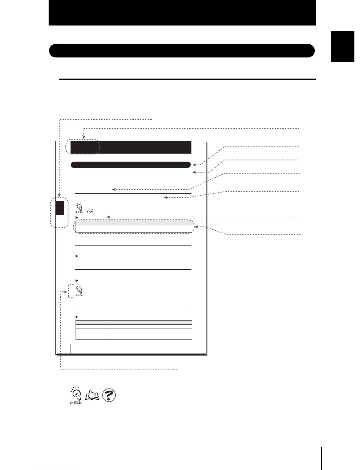
Editor's Note
Page Format
Index label
Indicates the section number and title.
Introduction
Precautions for Correct Use
Introduction
Title of each section
Section 3
Setting Banks
Setting Banks
The ZFV Series can hold up to eight sets of settings. These settings can be switched
externally when changing the device setup
A set of these settings is called a “bank.”
Switching banks
BANK 1 is selected as the default. BANK 2 and 8 are also available.
Section 3 SETUP
60
BANKs can also be switched from an external device.
Setting the bank switching method p.60
MENU mode-[BANK]
Setting Description
BANK 1~BANK 8
(default value: BANK 1)
Copying banks
Copy the settings of other bank numbers to an already selected bank number.
MENU Mode-[SYS1]-[BANKSET]-[COPY]
Clearing banks
“Clearing” deletes the settings of the currently selected bank number.
MENU Mode-[SYS1]-[BANKSET]-[CLEAR]
[SYS1], [SYS2] settings and RUN Mode display settings cannot be cleared.
Setting the bank switching method
Select how to switch banks.
MENU Mode-[SYS1]-[BANKSET]-[SWITCH]
Setting Description
KEY (default value) Banks are switched by the control keys on Amplifier Unit.
I/O Banks are switched by the control keys on Amplifier Unit and input lead sig-
ZFV
User’s Manual
Selects the target bank.
nals.
Switching by input lead signals is enabled only in the RUN mode.
Header
Overview
Cross-header
Overview of the
cross-header
Movement through
menus up to setting
items
Explanation of options
Supplementary Explanation
Helpful information regarding operation and reference
pages are introduced here using symbols.
ZFV
User’s Manual
7
Introduction
Introduction
Editor's Note
■ Meaning of Symbols
Menu items that are displayed on the Amplifier Unit’s LCD screen are indicated
enclosed by brackets [aa].
■ Visual Aids
Indicates points that are important to ensure full product performance, such as operational
precautions and application procedures.
Indicates pages where related information can be found.
Indicates information helpful in operation.
Indicates functions that can be set only when the setup menu has been switched
to EXP menu.
ZFV
8
User’s Manual

CONTENTS
Introduction
CONTENTS
Introduction
Precautions for Safe Use 4
Precautions for Correct Use 5
Editor's Note 7
Page Format 7
CONTENTS 9
SECTION 1 FEATURES 13
ZFV Smart sensor Features 14
Basic Configuration 16
Part Names and Functions 18
SECTION 2 INSTALLATION & CONNECTION 21
About Installation and Connection 22
Amplifier Unit 23
Attaching the ferrite core 23
Installing the Amplifier Unit 23
Section 1 Section 2 Section 3 Section 4
Gang mounting 27
About the I/O cable 31
Timing charts 34
Sensor Head 37
Attaching the ferrite core 37
Installing the mounting fixture 37
Installing the Sensor Head 38
Connecting the Sensor Head 40
ZFV
User’s Manual
9

Introduction
Introduction
CONTENTS
SECTION 3 SETUP 41
Setting Flow 42
About Setup 44
Basic Knowledge for Operation 44
List of Setting Items in MENU mode 46
Executing Teaching 48
Teaching Flow 48
Types of Teaching 51
Adjusting Threshold Values 55
Performing Measurement 59
Setting Banks 60
Switching banks 60
Copying banks 60
Clearing banks 60
Setting the bank switching method 60
Setting the System Environment 61
Adjusting the measurement speed 61
Selecting the measurement timing 61
Selecting the teaching mode from an external device 61
Setting/canceling the “Eco” mode 62
Initializing setup data 62
Initializing measurement data 62
Checking the version 63
Changing image capture timing on teaching screen 63
Setting communications environment 64
Changing the Input/output Conditions 65
Selecting the ON conditions 65
One-shot output 65
Setting the ON delay time 66
Setting the OFF delay time 67
I/O Monitor Function 68
Settings During Application Extended Connection 69
Specifying the Amplifier Unit to input the trigger 69
Setting the presence of Sensor Head 70
ZFV
10
User’s Manual

Introduction
CONTENTS
Setting output content 70
Customizing Measurement conditions 71
Introduction
Common items 71
PATTERN/SEARCH, MATCH 72
BRIGHT 73
AREA 74
WIDTH 75
POSITION 76
COUNT 77
CHARA/CHARA 1, CHARA 2 78
Saving the Set Measurement Conditions 82
SECTION 4 APPENDIX 83
Troubleshooting 84
Error Messages and Remedies 85
Q&A 86
Run Mode Display Item List 87
Section 1 Section 2 Section 3 Section 4
When Gang-mounting Amplifier Units 89
Gang-mounting example 89
Rules of gang-mounting 90
Data route 91
Teaching process when gang-mounting 92
Integrating judgment output 93
Restrictions when gang-mounting old and new amplifier units 94
Specifications and External Dimensions 95
Sensor Head 95
Amplifier Unit 97
Panel Mount Adapters 100
Control Link Unit 101
Extension Cord 102
Version Up Information 103
INDEX 105
Revision History 108
ZFV
User’s Manual
11

Introduction
Introduction
CONTENTS
MEMO
ZFV
12
User’s Manual

Section 1
FEATURES
ZFV Smart sensor Features 14
Basic Configuration 16
Part Names and Functions 18
Section 1 FEATURES
ZFV
User’s Manual
13
Section 1
ZFV Smart sensor Features
ZFV Smart sensor Features
Section 1 FEATURES
The ZFV sensor senses objects by its “surface.” How objects are being sensed can be
easily set while verifying on the LCD monitor.
The ZFV also incorporates a 250,000-pixel CCD equivalent to that of a Conventional
machine vision sensor. This allows presence detection and recognition of different objects,
which have up till now been performed visually, to be executed fast and accurately.
■ Recognition of top/rear side and orientation of electronic components
(1) Compact Sensor Head
The LED light emitting section and lens are built into the compact Sensor Head. The
Sensor Head takes up little installation space.
(2) Easy Installation and Adjustment
The range that can be sensed by Sensor Head can be confirmed by the guide light. So,
the Sensor Head can be installed by viewing the position of the guide light and its
focus.
ZFV
14
User’s Manual

Section 1
ZFV Smart sensor Features
(3) Business Card-size Amplifier Unit
• The Amplifier Unit is designed to be compact so that it can be installed at a wide
range of sites.
Specifications and External Dimensions p.95
• Outstanding operate ease has been achieved by a 1.8″color LCD motor, an industryfirst icon-based menu, and simple key layout.
Basic Knowledge for Operation p.44
• The ZFV incorporates an extensive range of measurement items which means that
numerous applications are supported.
Types of Teaching p.51
(4) Logging measured images (Ver. 2.0 and later)
Measurement images can be logged by connecting to data storage unit ZS-DSU. Set
NG occurrence as a trigger to log before/after images and measurement values. This is
useful for investigating the cause of defectives. Logged data is saved to the memory
card inserted into the data storage unit, and can be easily be loaded to a personal computer.
Section 1 FEATURES
Data Storage
Unit
OUTPUT
RUN
Personal Computer
Data storage unit ZS-DSU User's Manual
ZFV
(5) Enables bank extension (Ver. 2.0 and later)
A maximum 128 bank data items can be saved to the memory card mounted to the
data storage unit if connected to data storage unit ZS-DSU. Bank data can be transferred from the data storage unit to the ZFV as needed for the device setup.
Data storage unit ZS-DSU User's Manual
ZFV
User’s Manual
15

Section 1
Basic Configuration
Basic Configuration
Section 1 FEATURES
The figure below shows the Basic Configuration of the ZFV Series.
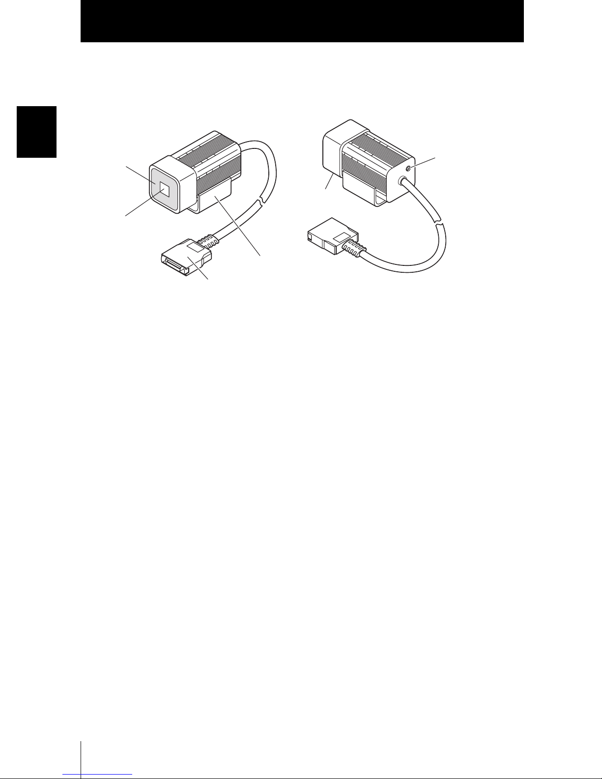
Sensor Head
Detects workpieces as images.
• Narrow view type ZFV-SR10
• Wide view type ZFV-SR50
Extension Cord
ZFV-XC3BV2(3m)/XC8BV2(8m)/XC3BRV2(3m)
Used between a Sensor Head and Amplifier Unit.
Two ZFV-XC B(R)V2 cords can be coupled together to
extend the cord length.
OUTPUT
RUN
Amplifier Unit
Used for confirming images and menus, performing measurement
processing, and outputting the result of processing.
• Single-function type ZFV-A10/-A15
• Standard type ZFV-A20/-A25
Power supply
DC24V (+10%, -15%)
Recommended OMRON power supply
(1) When 1 Amplifier Unit is connected
S82K-01524 (DC24V, 0.6A)
(2) When 2 or 3 Amplifier Units are connected
S82K-05024 (DC24V, 2.1A)
(3) When 4 or 5 Amplifier Units are connected
Prepare the required number of (1) and (2)
power supplies above.
■ Application Expanded Configuration
Up to five Amplifier Units can be gang-mounted.
When the Amplifier Unit is gang-mounted, a wider range of applications can be supported as simultaneous processing of multiple areas and measurement items can be
combined.
The image captured by the Sensor Head is transferred to the leftmost Amplifier Unit, so
connect to the rightmost Amplifier Unit.
Right
Wrong
• The maximum number of Amplifier Units that can be connected is five regardless of the number
of connected Sensor Heads.Six or more Amplifier Units cannot be connected.
• Provide power to all gang-mounted Amplifier Units.
Right
Wrong
ZFV
16
User’s Manual

Section 1
Basic Configuration
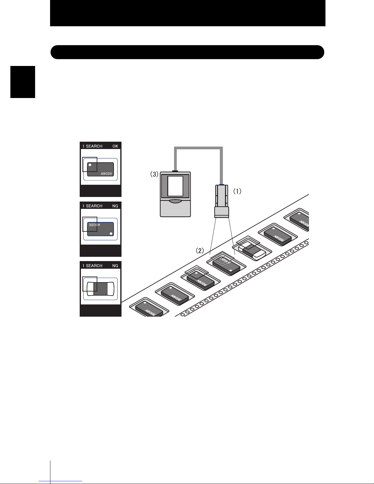
● Example 1
In this configuration, multiple parts of an image from a single Sensor Head are measured and multiple inspection item are performed.
Example) Inspection of the number of leads
Section 1 FEATURES
● Example 2
In this configuration, multiple Sensor heads are used to simultaneously inspect multiple
locations on a workpiece.
When the TRIG signal is input from a single specified Amplifier Unit, the connected
Amplifier Unit starts sensing immediately. The result of sensing is integrated on the
Amplifier Unit to which the TRIG signal was input, and is output as a total judgment
result.
Example) Alignment of products
AMP 1 AMP 2
NG1.SEARCH
NG1.SEARCH
OK1.SEARCH
AMP 3
NG1.SEARCH
OK1.SEARCH
OK1.SEARCH
NG1.SEARCH
AMP 1 AMP 2 AMP 3
NG1.SEARCH
OK1.SEARCH
Vitamin C
min C
ita
V
itamin C
V
ZFV
User’s Manual
17
Section 1
Part Names and Functions
Part Names and Functions
Section 1 FEATURES
The following describes the names and functions of parts on the Amplifier Unit and Sensor
Head.
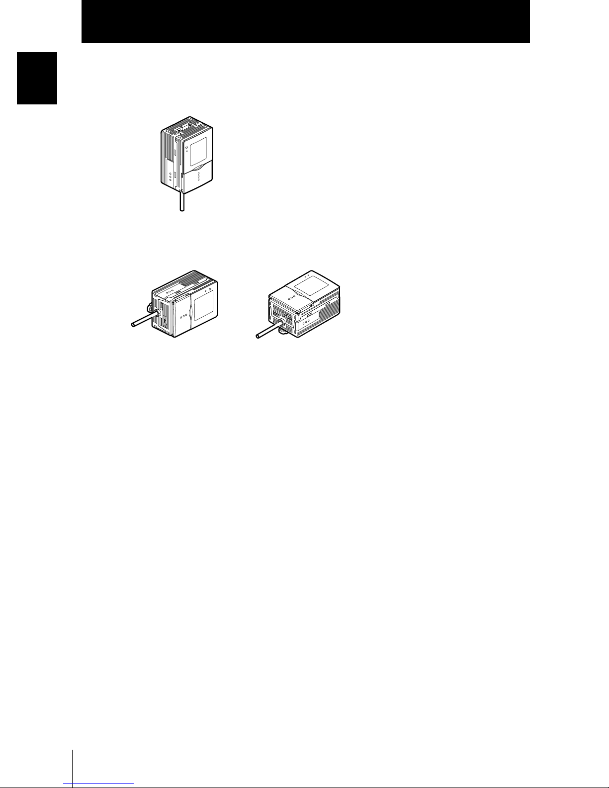
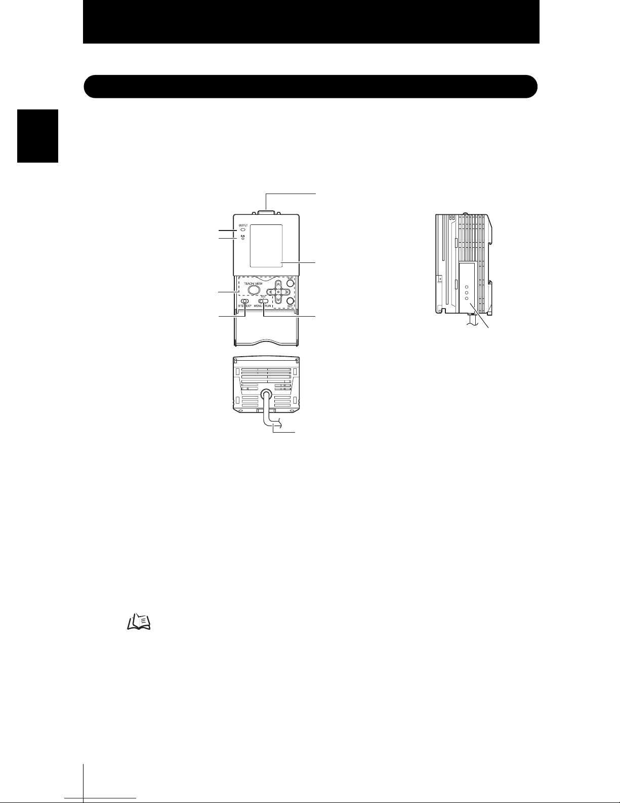
■ Amplifier Unit
(7) Sensor Head connector
(1) OUTPUT indicator
(2) RUN indicator
(6) LCD monitor
(3) Control keys
(4) Menu selector switch
(5) Mode selector switch
(8) Coupler
(9) I/O cable
(1) OUTPUT indicator
The Output indicator lits when the OUTPUT signal turns ON.
(2) RUN indicator
The RUN indicator turns ON in the RUN mode.
(3) Control keys
The Control Keys are for setting measurement conditions and other information.
Displays and Key Operations p.45
(4) Menu selector switch
This switch selects the setup menu.
STD...Standard menu. Select this when setting the minimum required items for
measurement.
EXP...Expert menu. Select this item when making a more detailed setup.
ZFV
18
User’s Manual

Section 1
Part Names and Functions
(5) Mode selector switch
This switch selects the operating mode.
MENU...Select this mode when setting measurement conditions.
ADJ...Select this mode when adjusting the judgment threshold value.
RUN...Select this mode when performing measurement.
Output is performed only when the RUN mode is currently selected.
(6) LCD monitor
The LCD monitor displays setup menus and images captured from the Sensor Head.
(7) Sensor Head connector
This connector connects the Sensor Head.
(8) Coupler
This connector is used to connect two or more Amplifier Units. It is located on both
sides of the Amplifier Unit.
Section 1 FEATURES
(9) I/O Cable
The I/O cable connects the Amplifier Unit to the power supply and external devices,
such as timing sensors or programmable controllers.
ZFV
User’s Manual
19
Section 1 FEATURES
Section 1
Part Names and Functions
■ Sensor Head
(1) Lighting part
(2) Receiver part
(3) Connector
(5) Focus adjustment
control
(6) Ventilation film
(4) Sensor Head mounting fixture
(1) Lighting part
This section emits light.
(2) Receiver part
This section captures the image.
(3) Connector
This connector is connected to the Amplifier Unit.
(4) Sensor Head mounting fixture
This fixture is for mounting the Sensor Head.
This fixture can be mounted on all of the four mounting surfaces.
(5) Focus adjustment control
This control is used for adjusting the focus of the image.
(6) Ventilation film
This film prevents the front panel from condensation.
ZFV
20
User’s Manual
Section 2
INSTALLATION & CONNECTION
About Installation and Connection 22
Amplifier Unit 23
Attaching the ferrite core 23
Installing the Amplifier Unit 23
Gang mounting 27
About the I/O cable 31
Timing charts 34
Sensor Head 37
Attaching the ferrite core 37
Installing the mounting fixture 37
Installing the Sensor Head 38
Connecting the Sensor Head 40
Section 2 INSTALLATION & CONNECTION
ZFV
User’s Manual
21

Section 2
About Installation and Connection
About Installation and Connection
■ Checking the installation environment
Read “Precautions for Safe Use” at the beginning of this manual, and check the installation environment.
Section 2 INSTALLATION & CONNECTION
■ Checking the installation site
Read “Precautions for Correct Use” at the beginning of this manual, and check the
installation site.
■ About the power supply
Before installing and connecting the Smart Sensor, be sure to turn it OFF.
Also read “Precautions for Safe Use” and “Precautions for Correct Use” at the beginning of this manual, and check the power supply and wiring.
ZFV
22
User’s Manual

Section 2
Amplifier Unit
Amplifier Unit
This section describes installation of the Amplifier Unit, and connection of the I/O cable.
Before connecting/disconnecting peripheral devices, make sure that the Smart Sensor is turned OFF.
The Smart Sensor may break down if the Smart Sensor is connected or disconnected while the power
is ON.
Attaching the ferrite core
Attach the ferrite core (provided with the Smart Sensor) to the I/O cable of the Amplifier
Unit.
Section 2 INSTALLATION & CONNECTION
Ferrite core
Installing the Amplifier Unit
■ Installing on the DIN track
Amplifier Units can be easily mounted on the 35-mm DIN track.
DIN track (sold separately)
PFP-100N (1 m)
PFP-50N (0.5 m)
PFP-100N2 (1 m)
ZFV
User’s Manual
End plate (sold separately)
PFP-M
23
Section 2
Amplifier Unit
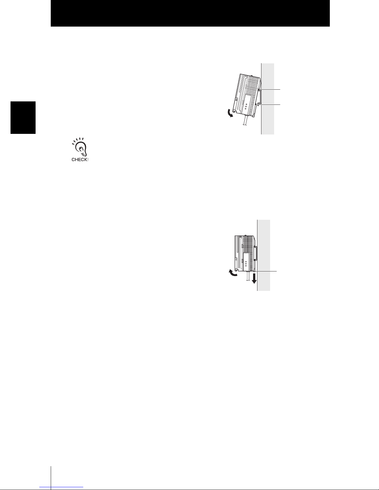
● Installation procedure
1. Hook the connector end of the Amplifier Unit
onto the DIN track.
Hook on connector
end
Section 2 INSTALLATION & CONNECTION
2. Push the Amplifier Unit down onto the DIN
track until the hook on the I/O cable side is
locked.
Push down until you hear it snap into place.
Always hook the connector end of the Amplifier Unit on the DIN track first. Hooking the I/O cable
end on the DIN track first may impair the mounting strength of the DIN track attachment.
● Removal procedure
The following describes how to remove the Amplifier Unit from the DIN track.
Hook on I/O cable
1. Pull the hook on the I/O cable end of the
Amplifier Unit downwards.
2. Lift up the Amplifier Unit from the I/O cable
end, and remove it from the DIN track.
Hook on I/O cable
ZFV
24
User’s Manual
Section 2
Amplifier Unit
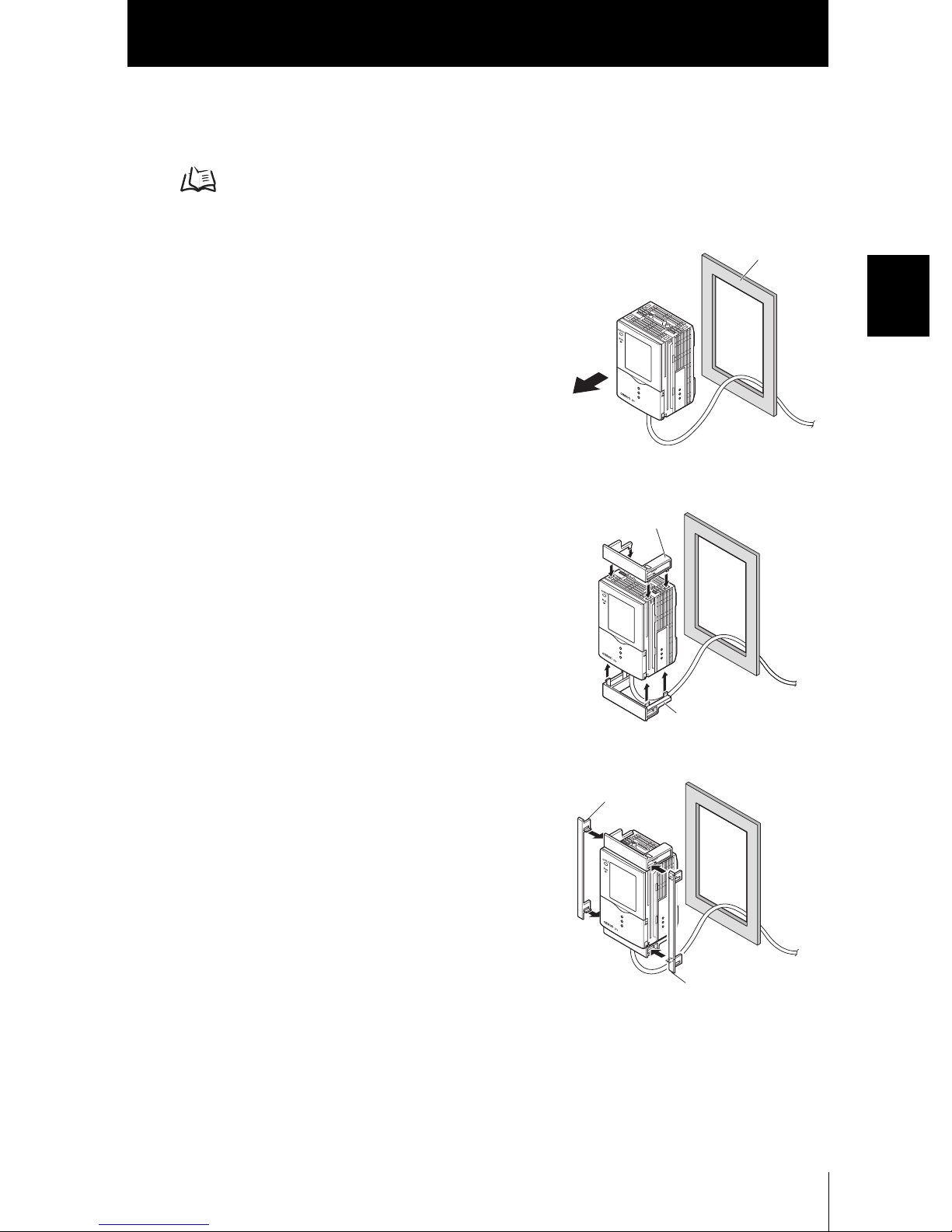
■ Mounting on a panel
The Panel Mount Adapters (sold separately ZS-XPM1) can be used to mount the
Amplifier Unit on a panel.
Panel Mount Adapters p.100
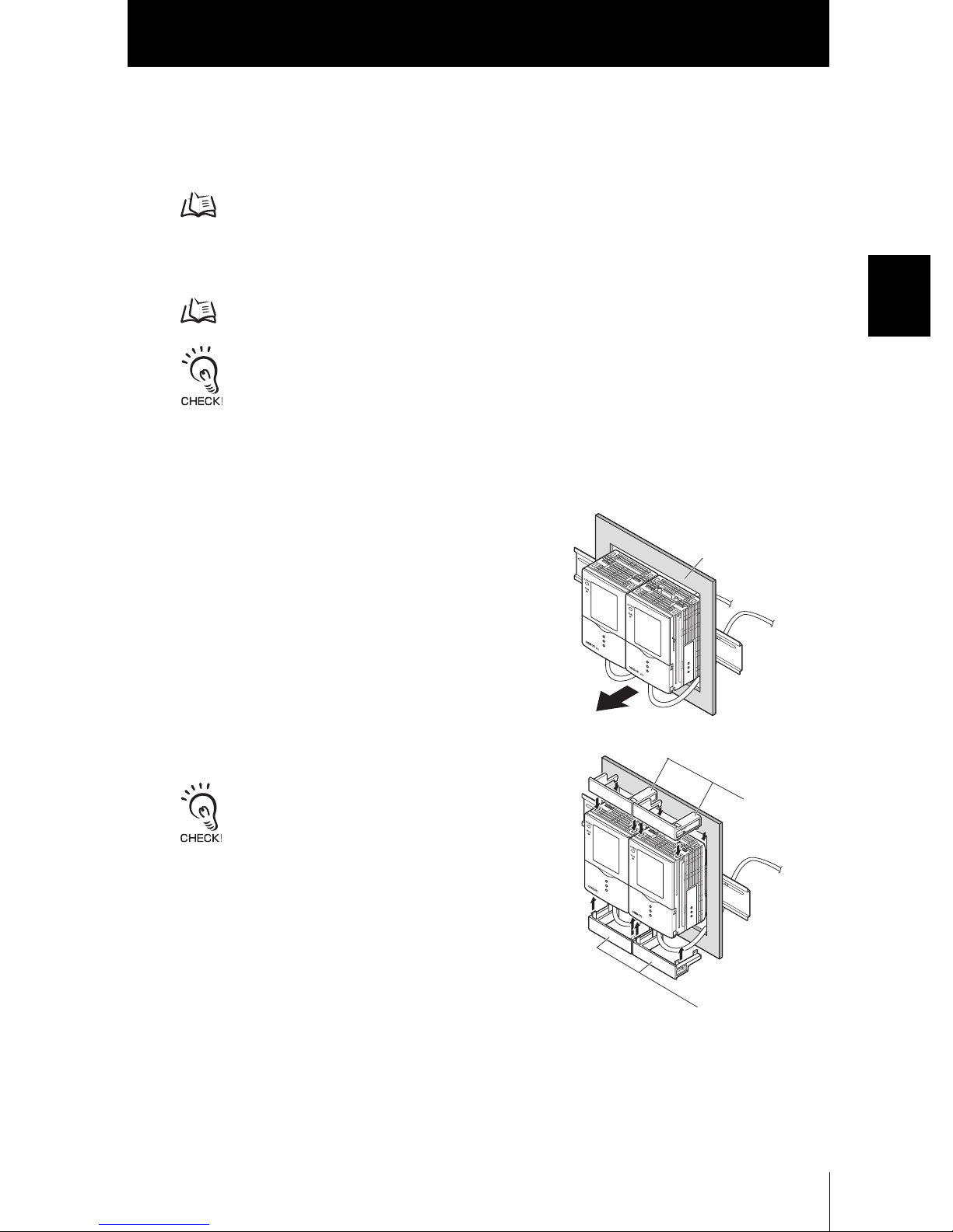
1. Push out the Amplifier Unit from the rear of
the panel towards the front.
2. Install the small Mount Adapters on the four
holes on the Amplifier Unit.
Panel Mount
Adapter
Panel
Section 2 INSTALLATION & CONNECTION
3. Install the long Mount Adapters on the two
holes on the small Mount Adapter.
Panel Mount
Adapter
Panel Mount
Adapter
Panel Mount
Adapter
ZFV
User’s Manual
25
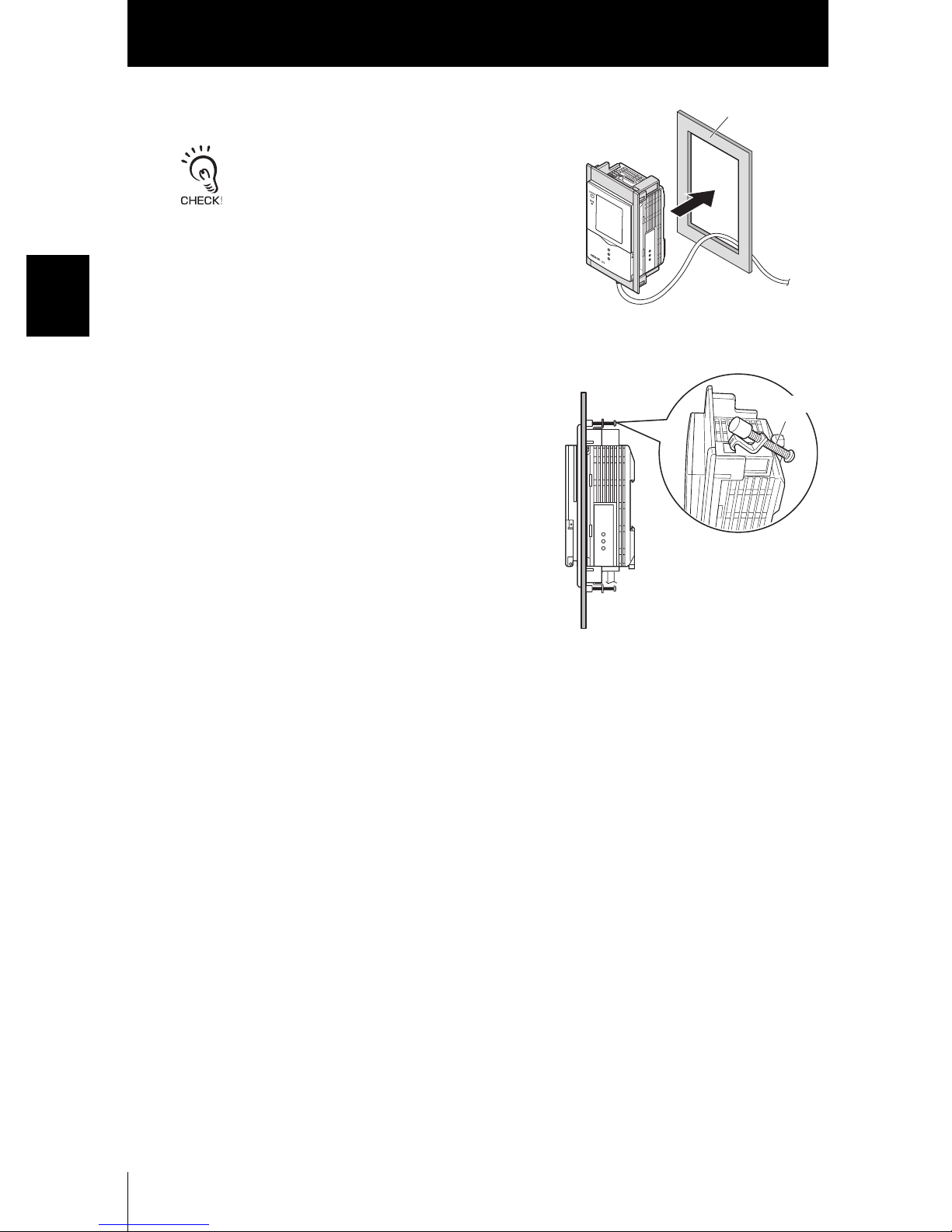
Section 2
Amplifier Unit
4. Install the Amplifier Unit with Mount Adapters
attached onto the panel from the front.
Take care not to pinch the I/O cable.
Section 2 INSTALLATION & CONNECTION
Panel
5. Hook the hooks of the mounting fixture onto
the two holes of the smaller Mount Adapters
and tighten the screws.
Mounting
fixture
6. Make sure that the Amplifier Unit is firmly
fixed on the panel.
ZFV
26
User’s Manual
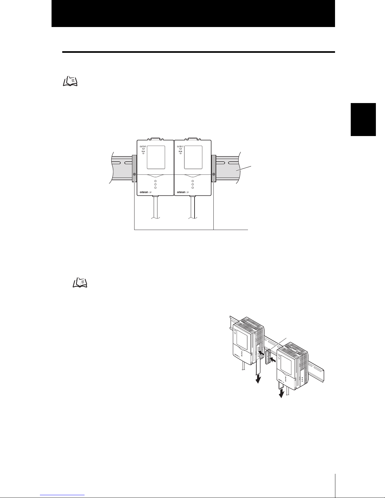
Gang mounting
Up to five Amplifier Units can be gang-mounted.
Application Expanded Configuration p.16
Section 2
Amplifier Unit
■ Installing on the DIN track
Amplifier Units can be easily mounted on the 35-mm DIN track.
● Installation procedure
1. Install Amplifier Unit on the DIN track.
p.24
Section 2 INSTALLATION & CONNECTION
DIN track (sold separately)
PFP-100N (1 m)
PFP-50N (0.5 m)
PFP-100N2 (1 m)
End plate (sold separately)
PFP-M
2. Open the connector cover on the Amplifier
Unit.
Slide the cover to remove.
3. Insert the Controller Link Unit into the
connector on the Amplifier Unit.
4. Slide the Amplifier Unit, and insert into the connector on the Controller Link Unit.
ZFV
User’s Manual
Controller
Link Unit
27
Section 2
Amplifier Unit
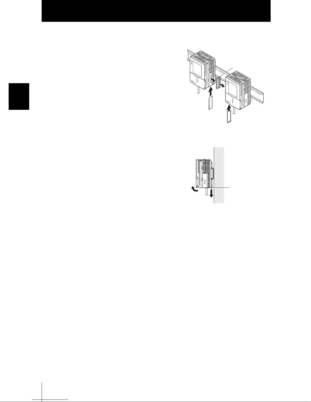
● Removal procedure
1. Slide the Amplifier Unit, and remove from the
connector on the Controller Link Unit.
Controller
Link Unit
Section 2 INSTALLATION & CONNECTION
2. Slide the Controller Link Unit and remove from
the connector on the Amplifier Unit.
3. Install the cover on the coupler of the Amplifier
Unit.
4. Pull the hook on the I/O cable end downwards.
5. Lift up the Amplifier Unit from the I/O cable
end, and remove it from the DIN track.
Hook on I/O cable
end
ZFV
28
User’s Manual
Section 2
Amplifier Unit
■ Mounting on a panel
The Panel Mount Adapters (sold separately ZS-XPM1/XPM2) can be used to mount
the Amplifier Unit on a panel.
Panel Mount Adapters p.100
1. Install the Amplifier Unit on the DIN track.
p.27
When mounting on a panel, be sure to install the DIN track on the rear side of the Amplifier Unit for
support.
2. Push out the Amplifier Unit from the rear of
the panel towards the front.
Section 2 INSTALLATION & CONNECTION
Panel
3. Install the small Mount Adapters on the four
holes on the Amplifier Unit.
Install the small Mount Adapters on all gang-mounted
Amplifier Units.
ZFV
User’s Manual
Panel
Mount
Adapter
Panel Mount Adapter
29
 Loading...