

Omron STC-HD853HDMI Owner's Manual

No. 17S142-00
STC-HD853HDMI
Product specifications and User’s guide
1/81
16:9 Format 2160p (4K UHDTV)
Color CMOS Camera
STC-HD853HDMI
Product Specifications and User’s guide

No. 17S142-00
STC-HD853HDMI
Product specifications and User’s guide
2/81
Table of Contents
1 Product Precautions ............................................................................................ 6
2 Warranty ................................................................................................................ 6
3 Introduction .......................................................................................................... 7
3.1 Features .................................................................................................................................... 7
3.2 Peripheral Equipment .............................................................................................................. 7
4 Specifications ....................................................................................................... 8
4.1 Electronic Specifications ......................................................................................................... 8
4.2 Spectral Sensitivity Characteristics ..................................................................................... 10
STC-HD853HDMI ............................................................................................................................. 10
IR Cut Filter ..................................................................................................................................... 10
4.3 Mechanical Specifications ..................................................................................................... 11
4.4 Environmental Specifications ............................................................................................... 11
4.5 External Control Specification .............................................................................................. 11
5 Dimensions ......................................................................................................... 12
6 Camera instruction guide .................................................................................. 13
6.1 Push Button ............................................................................................................................ 13
6.2 External Switch (Remote Controller) .................................................................................... 14
Camera Setting through Switch that has 3.5φStereo Pin Jack .................................................... 14
Menu on screen with External Switch ........................................................................................... 15
7 Control Software User’s Guide.......................................................................... 27
7.1 System Requirements ............................................................................................................ 27
7.2 Basic Operating Procedure ................................................................................................... 27
7.3 Button Descriptions ............................................................................................................... 28
7.4 The Difference of uCOM register and DSP register ............................................................. 28

No. 17S142-00
STC-HD853HDMI
Product specifications and User’s guide
3/81
7.5 Functional Description........................................................................................................... 29
8 The communication protocol specifications .................................................... 57
8.1 Communication settings........................................................................................................ 57
8.2 Communication format .......................................................................................................... 57
8.3 Camera control commands ................................................................................................... 58
The command list for the communication .................................................................................... 58
Slave address for the ICs (8 bits) list ............................................................................................. 60
Error code list ................................................................................................................................. 60
8.4 uCOM register mapping list ................................................................................................... 61
Push button function for OSD ........................................................................................................ 67
Push button function list ................................................................................................................ 67
8.5 DSP register mapping list ...................................................................................................... 68
8.6 OSCD (On Screen Character Display) Command ................................................................ 78
2 Bytes Command ........................................................................................................................... 78
2 Bytes consecutive Command ..................................................................................................... 79
9 Revisions ............................................................................................................ 80
No. 17S142-00
STC-HD853HDMI
Product specifications and User’s guide
4/81
Precautions for safe use
Please read carefully this “Precautions for safe use” before use the camera. Then the camera uses correctly with
agreeing with below notes.
In this “Precautions for safe use”, notes divides into “Warning” and “Caution” to use the camera safety and prevent to
harm and damage.
Warning
This shows, assumption for possibility of serious accident leading death or
serious injury if ignore this note and camera uses incorrectly.
Caution
This shows, assumption for possibility of bear the damage or physical
damage if ignore this note and camera uses incorrectly.
About Graphic
symbols
This symbol shows general prohibition.
This symbol shows completion or instruction.
[Environment / condition]
Warning
Do not use flammable or explosiveness
atmospheres.
This will cause of personal injury or fire.
Do not use for “safety for human body” related
usage.
This camera is designed for use “do not harm
human body immediately” if by any chance the
camera has malfunction.
Caution
Use and store under specified environmental
conditions (Vibration, shock, temperature,
humidity) in the specifications for this camera.
This will cause of fire or damage the camera.
[Installation and cable wiring]
Warning
Do not use with out of power voltage range
that is specified in the specifications for this
camera.
This will cause of fire, electrification or
malfunction.
Do not wrong wiring.
This will cause of fire or malfunction.
No. 17S142-00
STC-HD853HDMI
Product specifications and User’s guide
5/81
Caution
The camera housing is not connecting to 0 V
Line of camera inside circuit.
There is a risk of short circuit between camera
inside ciurcuit and frame ground through other
devices.
This will cause of malfunction.
It is necessary to wiring and mounting that is
specified in the specifications for this camera.
This will cause of fire or malfunction.
It is necessary to wiring with turn off the camera.
This will cause of electrification or malfunction.
It is necessary to mounting the camera without
stress for the cable.
This will case of electrification or fire.
[Usage instruction]
Warning
Do not touch the terminal and PCB board
While turn on the camera.
This will cause of electrification or accident
caused by malfunction.
Do not put combustibles near the camera.
This will cause of fire.
Do not use without usage that is specified in
the specifications for this camera.
This will cause of personal injury or malfunction.
Do not push metals including screw driver into
radiation holes.
This will cause of electrification or malfunction.
Caution
Do not push contamination into opening of
the camera.
This will cause of electrification or malfunction.
Do not block the radiation holes.
This will cause of fire due to increase the
camera inside temperature.
[Maintenance]
Caution
Do not disassemble or repair the camera.
This will cause of fire, electrification or
malfunction.
It is turn off the camera when maintaining or
inspecting the camera.
This will cause of electrification.
[Disposal]
Caution
It is necessary to dispose as industrial waste.
]

No. 17S142-00
STC-HD853HDMI
Product specifications and User’s guide
6/81
1 Product Precautions
Do not give shock to the camera.
Do not haul or damage the camera cable.
Do not wrap the camera with any material while using the camera. This will cause the internal camera
temperature to increase.
When the camera moving or using the place that temperature difference is extreme, countermeasure for dew
condensation (heat removal / cold removal) is necessary.
While the camera is not using, keep the lens cap on the camera to prevent dust or contamination from getting
in the sensor or filter and scratching or damaging it.
Do not keep the camera under the following conditions.
・ In wet, moist, high humidity or dusty place
・ Under direct sunlight
・ In extreme high or low temperature place
・ Near an object that releases a strong magnetic or electric filed
・ Place with strong vibrations
Apply the power that satisfies the specified in specifications for the camera.
The defective pixels may appear due to the sensor characteristics.
Use below recommend materials (or equivalent materials) to clean the surface of glass.
・ Air dust: Non Freon air duster (NAKABAYASHI Co., LTD.)
・ Alcohol: Propan-2-ol (SAN’EI KAKO Co., LTD.)
・ Non-woven: nikowipe clean room (NKB)
Use a soft cloth to clean the camera.
2 Warranty
■Warranty period
One year after delivery (However, the camera had malfunction with camera uses correctly)
In below case for a fee even within warranty period.
・The malfunction caused by incorrect usage, incorrect modify or repair.
・The malfunction caused by external shock including the camera dropping after delivery the camera.
・The malfunction caused by fire, earthquake, flood disaster, thunderbolt struck, other natural disaster or
wrong voltage.
■Warranty coverage
Exchange or repair the malfunction camera if the malfunction is occurred by our responsibility.
“Warranty” mean is warranty for the delivered camera itself. Please accept the induction damage by the
camera malfunction is not included.
No. 17S142-00
STC-HD853HDMI
Product specifications and User’s guide
7/81
3 Introduction
This document describes the specification of the following camera:
STC-HD853HDMI
3.1 Features
2160p or 1080p output is selectable
HDMI Output
CMOS rolling shutter
C mount
OSCD (On Screen Character Display) through Remoter Controller (Option)
Configurable many parameters through Control Software
Eight configurable DSP can be saved
Defective Pixel Correction (KPACtrl is required)
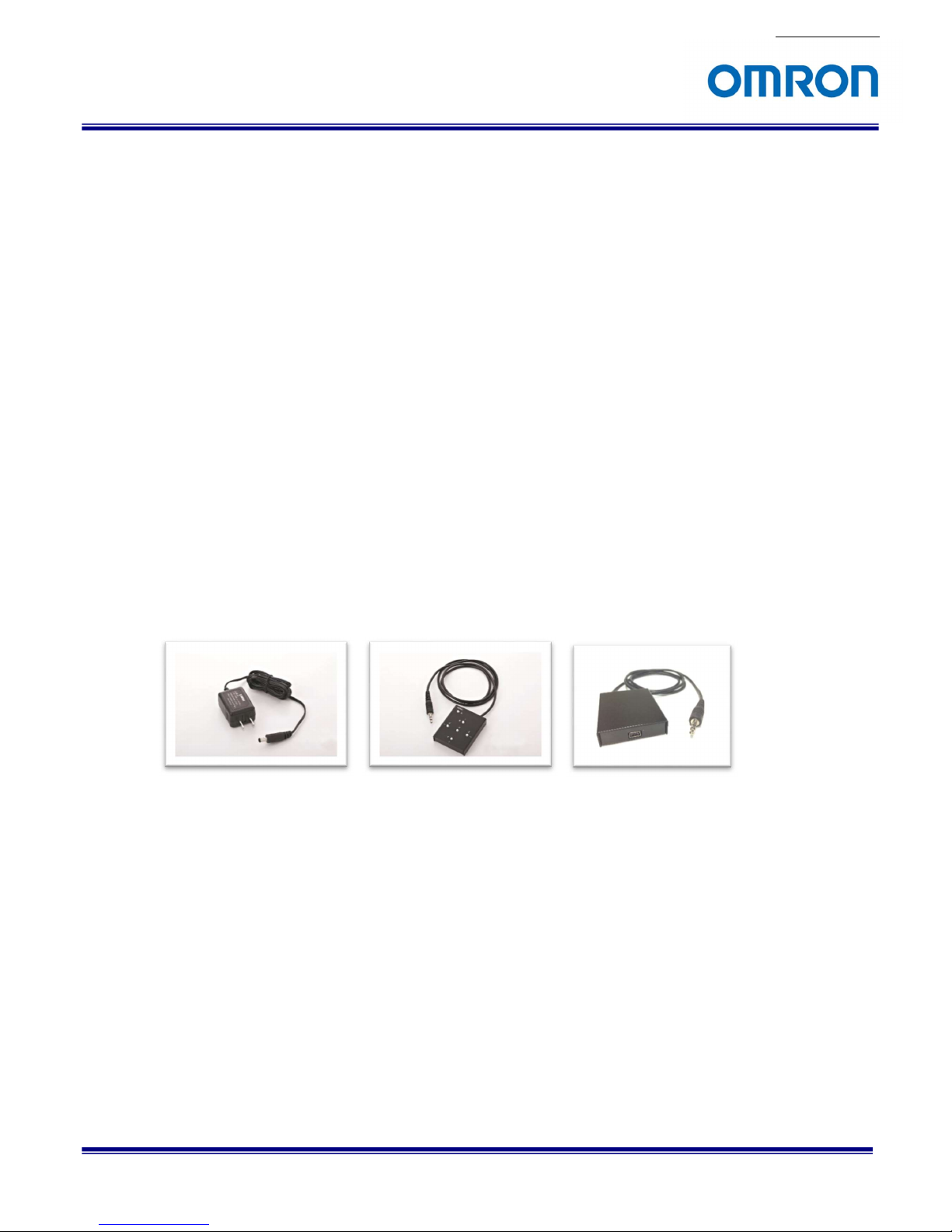
3.2 Peripheral Equipment
OMRON SENTECH provides as follow peripheral equipment as option.
(1) +12V DC Power Supply: UN310-1210
(2) Remote Controller: RC-HD133
(3) Communication Tool (PC can communicate through USB port): JIG-USB-HD
(4) Control Software: KPACtrl
(1) (2) (3)
No. 17S142-00
STC-HD853HDMI
Product specifications and User’s guide
8/81
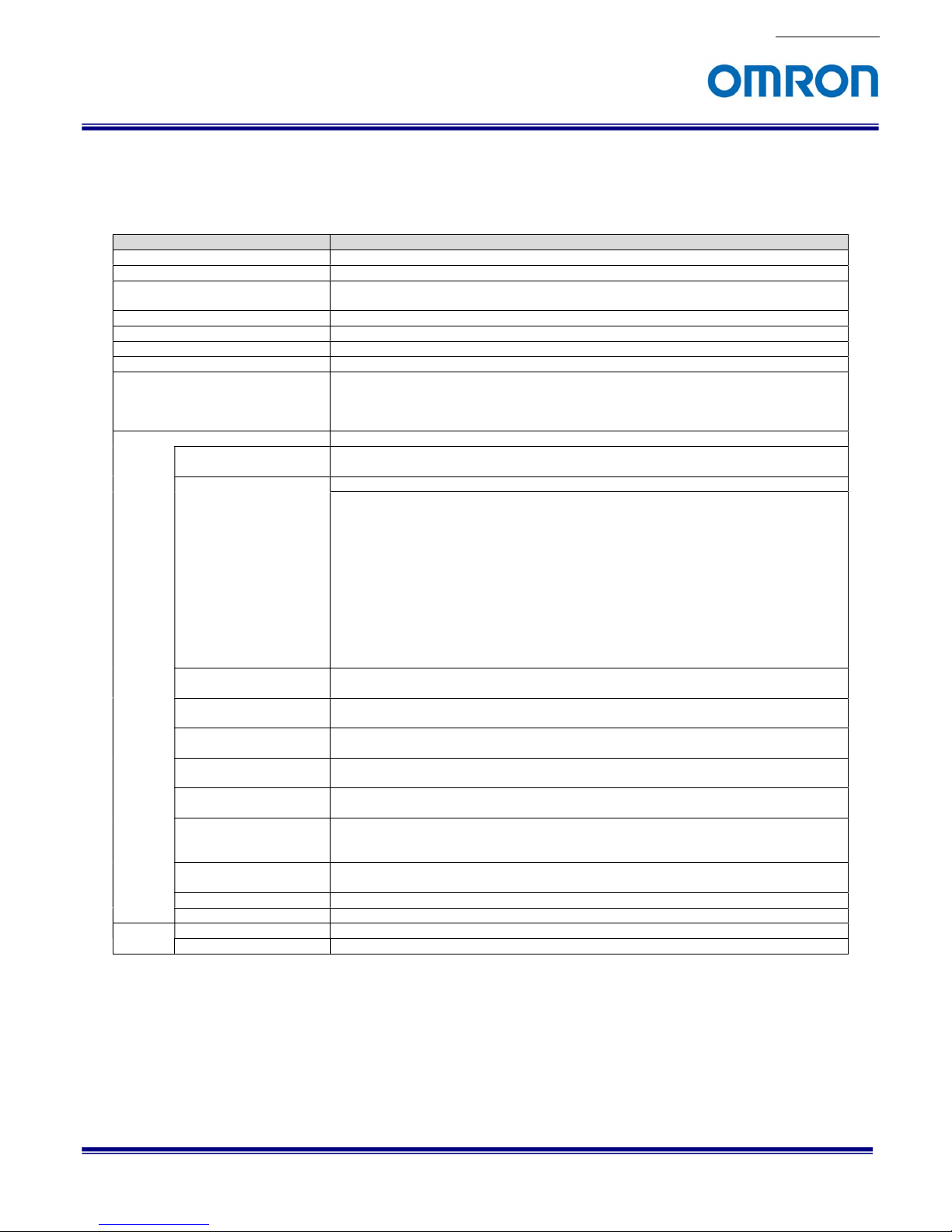
4 Specifications
4.1 Electronic Specifications
Product STC-HD853HDMI
Image Sensor 1/2.5" 8.51M Progressive CMOS (SONY)
Shutter Type Rolling shutter
Active Picture Elements 3,840 (H) x 2,160 (V) (QFHD),
1,920 (H) x 1,080 (V) (Full HD)
Chip Size 8.365 (H) x 6.615 (V) mm
Cell Size 1.62 (H) x 1.62 (V) µm
Sensitivity 1,070 Lux (*1)
Sync. System Internal
Video output HDMI (RGB 8bit 4:4:4)
2160P59.94 / 2160P60 / 2160P50 / 2160P29.97 / 2160P30 / 2160P25,
1080P59.94 / 1080P60 / 1080P50 / 1080P119.88 /1080P120 / 1080P100
(Default: Auto) (*2)
Camera Functions
ALC ALC mode (auto electronic shutter and AGC) is configurable via UART communication
(Default: ALC ON)
Shutter Speed Auto shutter or Fixed shutter selectable via UART communication (Default: Auto)
2160P59.94: 1/21737.3 seconds (46.0 μseconds) to 1/60.2 seconds (16.62 mseconds),
2160P60: 1/21737.3 seconds (46.0 μseconds) to 1/60.2 seconds (16.62 mseconds),
2160P50: 1/18218.6 seconds (54.9 μseconds) to 1/50.1 seconds (19.95 mseconds),
2160P29.97: 1/10959.9 seconds (91.2 μseconds) to 1/30.1 seconds (33.25 mseconds),
2160P30: 1/10959.9 seconds (91.2 μseconds) to 1/30.1 seconds (33.25 mseconds),
2160P25: 1/9173.1 seconds (109.0 μseconds) to 1/25.1 seconds (39.90 mseconds),
1080P59.94: 1/31266.9 seconds (32.0 μseconds) to 1/60.2 seconds (16.61 mseconds),
1080P60: 1/31266.9 seconds (32.0 μseconds) to 1/60.2 seconds (16.61 mseconds),
1080P50: 1/26383.3 seconds (37.9 μseconds) to 1/50.2 seconds (19.93 mseconds),
1080P119.88: 1/61071.4 seconds (16.4 μseconds) to 1/120.4 seconds (8.31 mseconds),
1080P120: 1/61071.4 seconds (16.4 μseconds) to 1/120.4 seconds (8.31 mseconds),
1080P100: 1/51724.1 seconds (19.3 μseconds) to 1/100.3 seconds (9.97 mseconds)
Gain AGC or Fixed gain selectable via the UART communication
0 to 27 dB
Gamma 8 preset gamma can be selectable (Manual / 0.30 / 0.45 / 0.50 / 0.60 / 0.70 / 0.80 / 0.90 / 1.00)
Gamma is selectable via UART communication (Default: Manual)
White Balance Auto white balance / manual white balance / push to set white balance
White balance is selectable via the UART communication (Default: Auto white balance)
Mirror Image Normal image / horizontal flip / vertical flip / horizontal vertical flip (180 deg. rotation)
(Default: Normal image)
DSP Preset Selectable 8 user preset modes can be selectable
User preset mode is selectable via UART communication (Default: Preset 0)
Line Generator Both horizontal and vertical with all available colors (Line number: 2)
Color, thickness and position for individual line are adjustable via UART communication
(Default: Disable)
Communication +3.3V UART communication via Φ 3.5 mm stereo jack
(Baud rate: 38,400 bps, 19,200 bps, 9,600 bps) (Default: 38,400 bps)
Character Generator Built-in character generation function via UART communication
Defective Pixel Correction
Up to 512 points (Default: ON)
Power Input voltage +9 to +15 Vdc (Typical: +12 Vdc)
Consumption 6.0 W
No. 17S142-00
STC-HD853HDMI
Product specifications and User’s guide
9/81
Precautions
(*1) The sensitivity is measuring the luminance when white level achieved 100 % in below conditions.
(*2) When selecting “Auto” at video output, video output format is selecting automatically based on connected
monitor supported format.
e.g. If the monitor supports up to 2160P30, video output format of camera selects 2160P30 automatically.
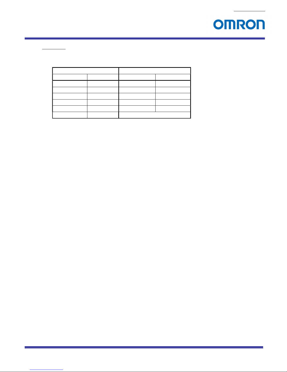
Camera Setting Environment
Parameter Setting Parameter Setting
Gain Up 0 dB Light Source Light Box (White)
AGC Off Color temperature 5,100K
White Balance Optimum Lens
Electrical Shutter 1/30 seconds F on Lens F5.6
Black Level Optimum Target Luminance IM-600 (Topcon)
Gamma Factory Setting
No. 17S142-00
STC-HD853HDMI
Product specifications and User’s guide
10/81
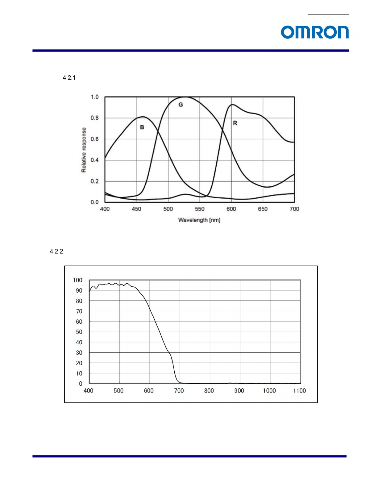
4.2 Spectral Sensitivity Characteristics
STC-HD853HDMI
IR Cut Filter
Wave Length (nm)
Transmittance
(%)
Spectrum Transmittance (Reference)
No. 17S142-00
STC-HD853HDMI
Product specifications and User’s guide
11/81
4.3 Mechanical Specifications
(*1) Excluding the connectors
(*2) Please use 2.5 µm or 2.2 µm resolution lens for 2160P output
(*3) Please use Φ 2.1 mm plug for power input connector
4.4 Environmental Specifications
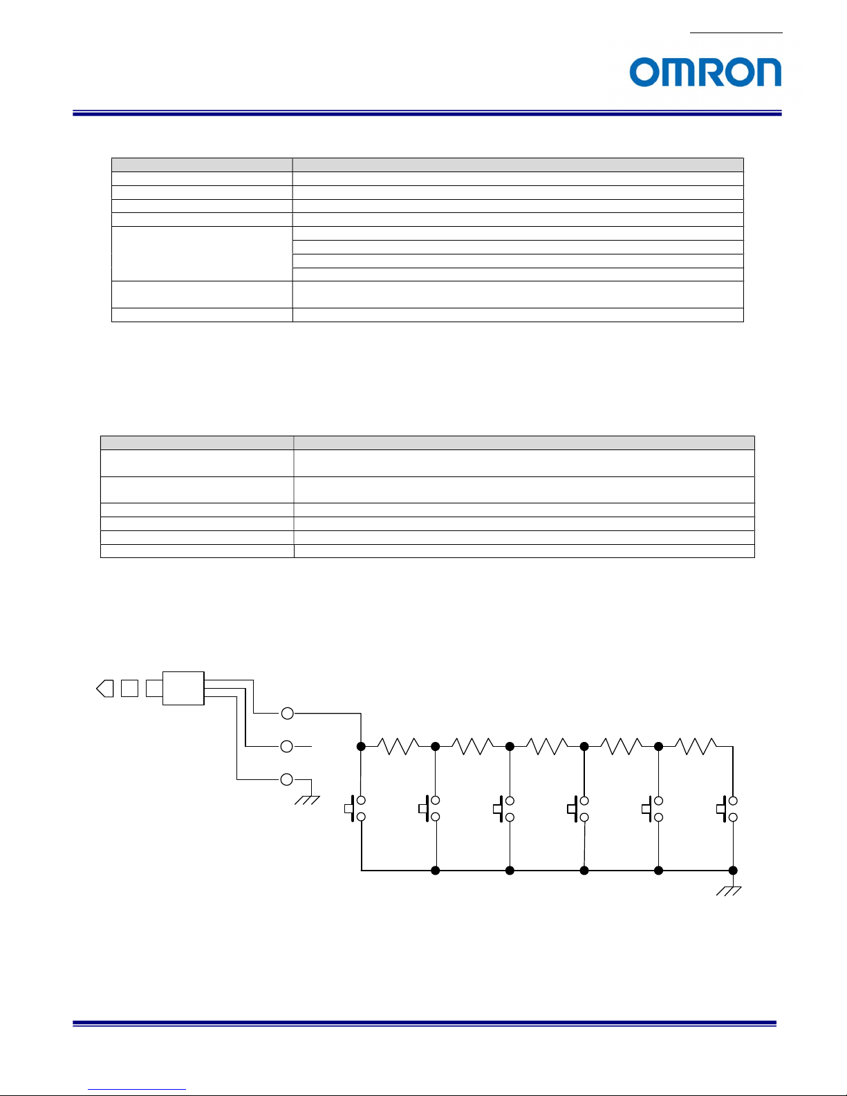
4.5 External Control Specification
Circuit Diagram of SW Board to connect 3.5φStereo Pin Jack
Product STC-HD853HDMI
Dimensions Φ 70 x 60 (H) x 50.7 (D) mm (*1)
Optical Filter IR cut filter with OPLF
Material Aluminum (AC)
Lens Mount C mount (*2)
Interface Connector Video Output: HDMI connector,
Power Input: Φ 2.5 mm power jack
External Control: Φ 3.5 mm stereo jack with SW board
Communication: Φ 3.5 mm stereo jack
Camera Mounting Two 1/4” tripod (One on top and bottom plate)
Sixteen M4 screw holes (Four on top, bottom, front and rear plate)
Weight Approximately 300 g
Product STC-HD853HDMI
Operational Temperature / Humidity Environmental Temperature: 0 to +40 deg. C,
Environmental Humidity: 0 to 80 %RH (No condensation)
Storage Temperature / Humidity Environmental Temperature: -10 to +75 deg. C,
Environmental Humidity: 0 to 80 %RH (No condensation)
Vibration 20 Hz to 200 Hz to 20 Hz (5 min. / cycle), acceleration 10 G, XYZ 3 directions 30 min. each
Shock Acceleration 38 G, half amplitude 6 msec., XYZ 3 directions 3 times each
Standard compliancy EMS: EN61000-6-2, EMI: EN55011
RoHS TBD
Tip
GND
SW-A SW-B SW-C SW-D SW-E SW-F
1 2
1 2
1 2
1 2
1 2
1 2
R1
1.8K
R2
3.3K
R3
4.7K
R4
10K
R5
27K
No. 17S142-00
STC-HD853HDMI
Product specifications and User’s guide
12/81
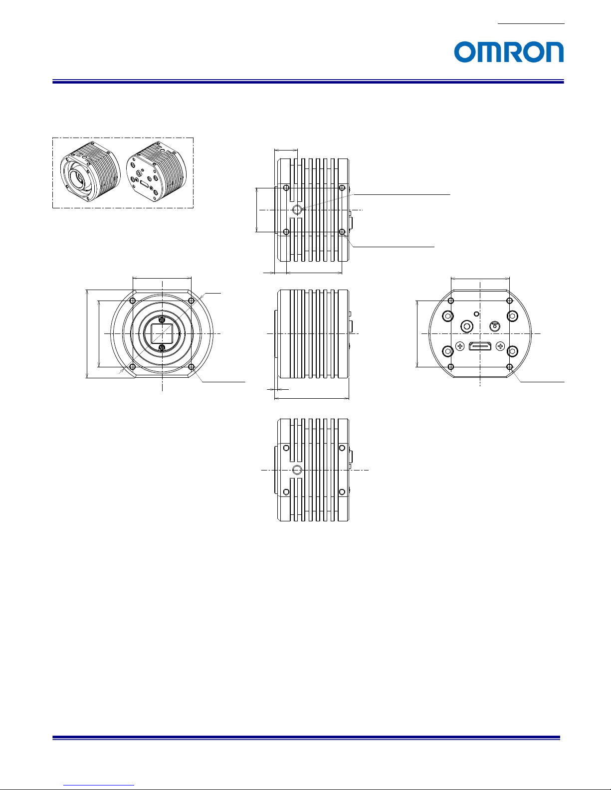
5 Dimensions
Unit: mm
40
φ 70
4-M4 depth 5.0
2
50.5
388
4-M4 depth 5.0
(Four on top, four on bottom)
40
4-M4 depth 5.0
15.5
30
45
60
45
Screw for camera tripod depth 6.0
(One on top, one on bototm)
No. 17S142-00
STC-HD853HDMI
Product specifications and User’s guide
13/81
6 Camera instruction guide
This camera can be set camera settings through three methods in below.
A. Push Button
B. External Switch (Remote controller: RC-HD133, separate accessory)
C. Control software (KPACtrl) (Communication tool: JIG-USB-HD, separate accessory)
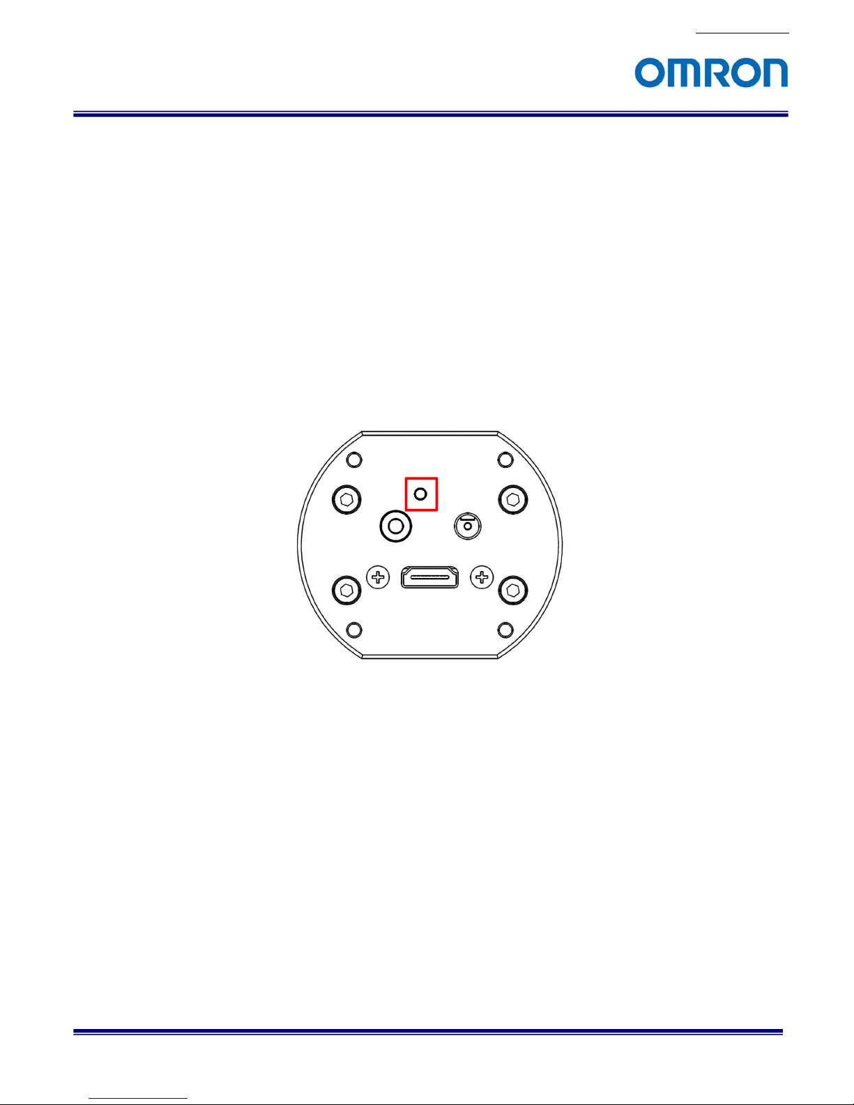
6.1 Push Button
White Balance can be set through push button. (*1)
Single Push: Push to set White Balance
Hold: Auto White Balance
Push button position
(*1) This push button can be assigned another function through control software

No. 17S142-00
STC-HD853HDMI
Product specifications and User’s guide
14/81
6.2 External Switch (Remote Controller)
Remote controller (Model:RC-HD133) is option, remote controller is separate accessory.
Camera Setting through Switch that has 3.5φStereo Pin Jack
A. Please assign function for each button on switch through control software in advance
B. Connector
3.5φStereo Pin Jack position
C. Switch Circuit Diagram
D. Switch Example
E. Switch Function
The default function assigns for SW-A to SW-F as follow functions.
SW-A: Display OSD Menu
SW-B: Up Cursor (Menu and Select Setting)
SW-C: Left Cursor (Select Setting)
SW-D: Execute
SW-E: Right Cursor (Select Setting)
SW-F: Down Cursor (Menu and Select Setting)
Tip
GND
SW-A SW-B SW-C SW-D SW -E SW-F
1 2
1 2
1 2
1 2
1 2
1 2
R1
1.8K
R2
3.3K
R3
4.7K
R4
10K
R5
27K
SW-A
SW-B
SW-D
SW-C SW-E
SW-F
No. 17S142-00
STC-HD853HDMI
Product specifications and User’s guide
15/81
Menu on screen with External Switch
Page 1
1) ALC
Selects the auto exposure (AEE) and auto gain (AGC) operation mode from below two modes.
Selection: ON / OFF
Default: ON
a) ON
The auto exposure and AGC operation mode, which is expose and gain adjust automatically based on
brightness of image.
b) OFF
The fixed exposure and fixed gain operation mode (auto exposure and AGC are OFF),
which is fixed exposure time controls by “SHUTTER” and fixed gain controls by “GAIN” manually.
2) LUMINANCE
Sets the target Brightness for ALC operation.
The brightness of image maintains by auto exposure and AGC operation.
Setting range: 0 (Dark) to 255 (Bright)
Default: 100
3) AGC
Sets the gain mode for ALC operation from below two modes.
Selection: AUTO / FIXED
Default: AUTO
a) AUTO
The AGC for ALC operation. which is gain adjust automatically based on brightness of image.
b) FIXED
The fixed gain for ALC operation.
The fixed gain controls by “GAIN” manually.
PAGE 1 2 3 4 5 6
ALC ON
LUMINANCE 100
AGC ON
AEE ON
GAIN
SHUTTER
GAMMA MANUAL

No. 17S142-00
STC-HD853HDMI
Product specifications and User’s guide
16/81
4) AEE
Sets the exposure mode for ALC operation from below two modes.
Selection: AUTO / FIXED
Default: AUTO
a) AUTO
The auto exposure for ALC operation, which is exposure adjusts automatically based on brightness of
image.
b) FIXED
The fixed exposure for ALC operation.
The fixed exposure time controls by “SHUTTER” manually.
5) GAIN
Sets the fixed gain, which is valid when “OFF” is selecting at “ALC” or “FIXED” is selecting at “GAIN”.
Setting range: 0 (0.00 dB) to 392 (27.05 dB)
6) SHUTTER
Sets the fixed exposure time, which is valid when “OFF” is selecting at “ALC” or “FIXED” is selecting
at “AEE”.
Setting range:
0 (1/60.2 sec.) to 746 (1/21737.3 sec.) at 2160P59.94
0 (1/60.2 sec.) to 746 (1/21737.3 sec.) at 2160P60
0 (1/50.1 sec.) to 746 (1/18218.6 sec.) at 2160P50
0 (1/30.1 sec.) to 746 (1/10959.9 sec.) at 2160P29.97
0 (1/30.1 sec.) to 746 (1/10959.9 sec.) at 2160P30
0 (1/25.1 sec.) to 746 (1/9173.10 sec.) at 2160P25
0 (1/60.2 sec.) to 746 (1/31266.9 sec.) at 1080P59.94
0 (1/60.2 sec.) to 746 (1/31266.9 sec.) at 1080P60
0 (1/50.2 sec.) to 746 (1/26383.3 sec.) at 1080P50
0 (1/120.4 sec.) to 746 (1/61071.4 sec.) at 1080P119.88
0 (1/120.4 sec.) to 746 (1/61071.4 sec.) at 1080P120
0 (1/100.3 sec.) to 746 (1/51724.1 sec.) at 1080P100
7) GAMMA
Selects the Gamma from below nine gamma selection.
It is necessary to set the manual gamma setting with control software through PC.
Setting selection: MANUAL / 0.30 / 0.45 / 0.50 / 0.60 / 0.70 / 0.80 / 0.90 / 1.00
Default: MANUAL (optimal gamma setting)

No. 17S142-00
STC-HD853HDMI
Product specifications and User’s guide
17/81
Page 2
1) WB MODE
Selects the white balance mode from below two modes.
Selection: AUTO / MANUAL
Default: AUTO
a) AUTO
The auto white balance operation.
b) MANUAL
The manual white balance operation.
The manual white balance adjusts by “R GAIN” and “B GAIN”.
2) R GAIN
Sets the manual R gain for manual white balance.
This is valid when “MANUAL” is selecting at “WB MODE”.
Setting range: 0 to 1,023
3) G GAIN
Sets the G gain for white balance.
Setting range: 0 to 1,023
Default: 256
4) B GAIN
Sets the manual B gain for manual white balance.
This is valid when “MANUAL” is selecting at “WB MODE”.
Setting range: 0 to 1,023
PAGE 1 2 3 4 5 6
WB MODE AUTO
R GAIN
G GAIN 0256
B GAIN
SHARPNESS H04 V04
CORING 03

No. 17S142-00
STC-HD853HDMI
Product specifications and User’s guide
18/81
5) SHARPNESS
Sets the Sharpness (Edge Enhancement) of image.
a) H
Sets the sharpness for horizontal direction.
Setting range: 00 (Soft) to 15 (Strong)
Default: 04
b) V
Sets the sharpness for vertical direction.
Setting range: 00 (Soft) to 15 (Strong)
Default: 04
6) CORING
The noise level also emphasizes when using sharpness function.
The SN ratio deteriorates for other than edge parts is prevented by cutting signal level that smaller than
this setting.
(The image becomes soft image if this setting sets too large.)
Setting range: 0 to 63
Default: 03

No. 17S142-00
STC-HD853HDMI
Product specifications and User’s guide
19/81
Page 3
1) LINE
Selects enable or disable for Line markers display.
Four horizontal and four vertical line makers can be display.
This setting is linked “LINE” setting on PAGE 4.
Selection: ON / OFF
Default: ON
a) ON
The line makers can be display.
b) OFF
Line Markers do NOT display.
PAGE 1 2 3 4 5 6
LINE ON
LINE1 H POS 0000 SIZE 0000
COLOR BLACK
V POS 0000 SIZE 0000
COLOR BLACK
LINE2 H POS 0000 SIZE 0000
COLOR BLACK
V POS 0000 SIZE 0000
COLOR BLACK

No. 17S142-00
STC-HD853HDMI
Product specifications and User’s guide
20/81
2) LINE1, LINE2
Sets the color, size (thickness) and position for each line.
a) H POS
Sets the position for horizontal line.
Setting range: 0 (Top) to 2,160 (Bottom)
Default: 0
b) H SIZE
Sets the size (thickness) for horizontal line.
Setting range: 0 (0 line, no horizontal line) to 2,160 (2,160 lines)
Default: 0
c) H COLOR
Selects the color for horizontal line from below sixteen selections.
It is necessary to set the USER0 to USER7 color by control software through PC.
Setting selection: BLACK / WHITE / RED / GREEN / BLUE / CYAN / MAGENTA / YELLOW /
USER0 / USER1 / USER2 / USER3 / USER4 / USER5 / USER6 / USER7
Default: BLACK
d) V POS
Sets the position for vertical line.
Setting range: 0 (Left) to 3,840 (Right)
Default: 0
e) V SIZE
Sets the size (thickness) for vertical line.
Setting range: 0 (0 pixel, no vertical line) to 3,840 (3,840 pixels)
Default: 0
F) V COLOR
Selects the color for vertical line from below sixteen selections.
It is necessary to set the USER0 to USER7 color by control software through PC.
Setting selection: BLACK / WHITE / RED / GREEN / BLUE / CYAN / MAGENTA / YELLOW /
USER0 / USER1 / USER2 / USER3 / USER4 / USER5 / USER6 / USER7
Default: BLACK

No. 17S142-00
STC-HD853HDMI
Product specifications and User’s guide
21/81
Page 4
1) LINE
Selects enable or disable for Line markers display.
Four horizontal and four vertical line makers can be display.
This setting is linked “LINE” setting on PAGE 3.
Selection: ON / OFF
Default: ON
a) ON
The line makers can be display.
b) OFF
Line Markers do NOT display.
PAGE 1 2 3 4 5 6
LINE ON
LINE3 H POS 0000 SIZE 0000
COLOR BLACK
V POS 0000 SIZE 0000
COLOR BLACK
LINE4 H POS 0000 SIZE 0000
COLOR BLACK
V POS 0000 SIZE 0000
COLOR BLACK

No. 17S142-00
STC-HD853HDMI
Product specifications and User’s guide
22/81
2) LINE3, LINE4
Sets the color, size (thickness) and position for each line.
a) H POS
Sets the position for horizontal line.
Setting range: 0 (Top) to 2,160 (Bottom)
Default: 0
b) H SIZE
Sets the size (thickness) for horizontal line.
Setting range: 0 (0 line, no horizontal line) to 2,160 (2,160 lines)
Default: 0
c) H COLOR
Selects the color for horizontal line from below sixteen selections.
It is necessary to set the USER0 to USER7 color by control software through PC.
Setting selection: BLACK / WHITE / RED / GREEN / BLUE / CYAN / MAGENTA / YELLOW /
USER0 / USER1 / USER2 / USER3 / USER4 / USER5 / USER6 / USER7
Default: BLACK
d) V POS
Sets the position for vertical line.
Setting range: 0 (Left) to 3,840 (Right)
Default: 0
e) V SIZE
Sets the size (thickness) for vertical line.
Setting range: 0 (0 pixel, no vertical line) to 3,840 (3,840 pixels)
Default: 0
F) V COLOR
Selects the color for vertical line from below sixteen selections.
It is necessary to set the USER0 to USER7 color by control software through PC.
Setting selection: BLACK / WHITE / RED / GREEN / BLUE / CYAN / MAGENTA / YELLOW /
USER0 / USER1 / USER2 / USER3 / USER4 / USER5 / USER6 / USER7
Default: BLACK
No. 17S142-00
STC-HD853HDMI
Product specifications and User’s guide
23/81
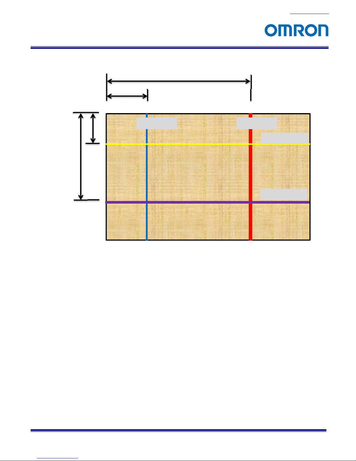
The example of display lines
Vertical line 1
Vertical line 2
Horizontal line 1
Horizontal line 2
LINE1 V POS
LINE2 V POS
LINE1 H POS
LINE2 H POS

No. 17S142-00
STC-HD853HDMI
Product specifications and User’s guide
24/81
Page 5
1) RES / FPS
Selects the image format and frame rate for video output from below twelve output formats.
Please selects the video output format and frame rate to meet specifications of monitor or capturing devices.
When selecting “AUTO”, the camera checks maximum supported video output format and frame rate of
connecting monitor or capturing devices then selects video format and frame rate automatically.
Setting selection:
2160P 59.94 / 2160P 60 / 2160P 50 / 2160P 29.97 / 2160P 30 / 2160P 25 /
1080P 59.94 / 1080P 60 / 1080P 50 / 1080P 119.88 / 1080P 120 /1080P 100 / AUTO
Default: AUTO
2) OSD SIZE
Sets the character size of OSD from below eight sizes.
Selection: x1 / x2 / x3 / x4 / x5 / x6 / x7 / x8
Default: x2
3) PROFILE
Preset data PRESET0 to PRESET7 can be apply to the camera.
To change the PRESET, select PRESET and use SAVE function after change the settings.
Setting selection: PRESET0 / PRESET1 / PRESET2 / PRESET3 / PRESET4 / PRESET5 /
PRESET6 / PRESET7
Default: PRESET0
PAGE 1 2 3 4 5 6
RES / FPS AUTO
OSD SIZE x2
PROFILES PRESET0
PATTERNS OFF
IMAGE OUTPUT STANDARD
No. 17S142-00
STC-HD853HDMI
Product specifications and User’s guide
25/81
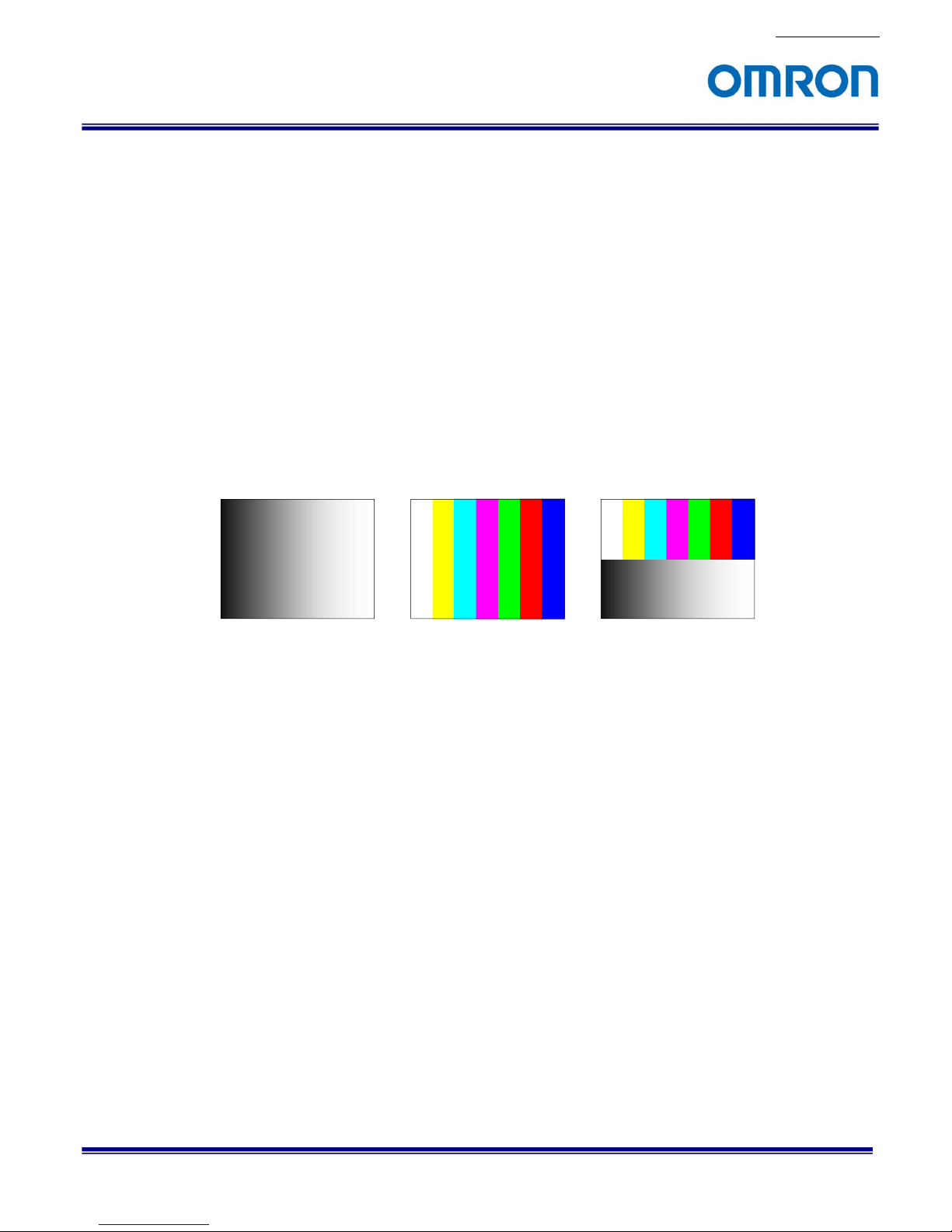
4) PATTERNS
Selects the output signal from below four output signals.
The test pattern can be output from camera to adjust monitor.
Selection: OFF / GRAY / COLOR / GRAY+COLOR
Default: OFF (Video output)
a) OFF
The video is output from camera.
b) GRAY
The gray scale test pattern is output from camera.
c) COLOR
The color test pattern is output from camera.
d) GRAY+COLOR
The color pattern (Top) + gray scale (Bottom) test pattern is output from camera.
5) IMAGE OUTPUT
Selects the flip image setting for video output from below four flip modes.
This setting does NOT apply for the test pattern outputs.
Selection: STANDARD / H INVERSION / V INVERSION / HV INVERSION
Default: STANDARD
a) STANDARD
The normal image (no-flip).
b) INVERSION
The horizontal flip image.
c) V INVERSION
The vertical flip image.
d) HV INVERSION
The horizontal and vertical flip (180 deg. rotate) image.
 Loading...