

Omron STC-CMC4MPOE, STC-CMB2MPOE, STC-CMC2MPOE, STC-CMB4MPOE-IR, STC-CMB2MPOE-IR Product Specifications And User's Manual
...Page 1

GigE Vision
Color / Monochrome CMOS PoE Camera
STC-CMB2MPOE (2M / Monochrome)
STC-CMC2MPOE (2M / Color)
STC-CMB2MPOE-IR (2M / Near IR)
No.13S064-13
STC-CMB4MPOE (4M / Monochrome)
STC-CMC4MPOE (4M / Color)
STC-CMB4MPOE-IR (4M / Near IR)
Product Specifications and User’s Guide
STC-CMC2MPOE / STC-CMB2MPOE / STC-CMB2MPOE-IR /
STC-CMC4MPOE / STC-CMB4MPOE / STC-CMB4MPOE-IR Product Specifications and User’s Guide
1/55
Page 2

No.13S064-13
Table of Contents
1 Product Precautions ............................................................................................ 7
2 Warranty ................................................................................................................ 7
3 Introduction .......................................................................................................... 8
3.1 Features .................................................................................................................................... 8
3.2 Product Number Naming Method ........................................................................................... 8
4 Specifications ....................................................................................................... 9
4.1 Electronic Specifications ......................................................................................................... 9
STC-CMB2MPOE / STC-CMC2MPOE ............................................................................................... 9
STC-CMB4MPOE / STC-CMC4MPOE ............................................................................................. 10
STC-CMB2MPOE-IR / STC-CMB4MPOE-IR ..................................................................................... 11
4.2 Spectral Sensitivity Characteristics ..................................................................................... 12
STC-CMB2MPOE / STC-CMB4MPOE ............................................................................................. 12
STC-CMC2MPOE / STC-CMC4MPOE ............................................................................................. 12
STC-CMB2MPOE-IR / STC-CMB4MPOE-IR (Near IR Model) ......................................................... 13
4.3 Mechanical Specifications ..................................................................................................... 14
4.4 Environmental Specifications ............................................................................................... 14
5 Connector Specifications .................................................................................. 15
5.1 RJ45 Connector ...................................................................................................................... 15
5.2 Power and Control Signal Connector ................................................................................... 16
Equivalent Circuit for the Input Pin of the I/O Connector ............................................................. 18
Typical Input Circuit ........................................................................................................................ 19
Typical Output Circuit ..................................................................................................................... 20
Input and Output Signal Timing (Hardware Trigger) ..................................................................... 21
Input and Output Signal Timing (Software Trigger) ...................................................................... 22
6 Dimensions ......................................................................................................... 23
7 Sensor information ............................................................................................ 24
7.1 Pixel Transferring Image ........................................................................................................ 24
STC-CMC2MPOE / STC-CMB2MPOE / STC-CMB2MPOE-IR /
STC-CMC4MPOE / STC-CMB4MPOE / STC-CMB4MPOE-IR Product Specifications and User’s Guide
2/55
Page 3

No.13S064-13
8 Camera Operational Modes ............................................................................... 25
8.1 Normal Mode ........................................................................................................................... 25
8.2 Pulse width trigger mode....................................................................................................... 25
Timing .............................................................................................................................................. 25
Exposure Timing with the Positive Polarity Trigger Signal .......................................................... 26
Exposure Timing with the Negative Polarity Trigger Signal ........................................................ 26
8.3 Edge Preset Trigger Mode ..................................................................................................... 27
Timing .............................................................................................................................................. 27
Exposure Timing with the Positive Polarity Trigger Signal .......................................................... 28
Exposure Timing with the Negative Polarity Trigger signal ......................................................... 28
8.4 Edge Preset Trigger Mode (Trigger Input While the Image Is Out) ..................................... 29
Timing .............................................................................................................................................. 29
9 Camera Functions .............................................................................................. 30
9.1 ROI (Region of Interest) ......................................................................................................... 30
ROI (1 region) .................................................................................................................................. 30
9.2 Pixel Format ............................................................................................................................ 32
9.3 Binning .................................................................................................................................... 32
9.4 Gain ......................................................................................................................................... 33
Digital gain ...................................................................................................................................... 33
9.5 Black level ............................................................................................................................... 33
9.6 ALC (Auto Light Control) ....................................................................................................... 34
ALC control method........................................................................................................................ 35
AGC (Auto Gain Contorl) ................................................................................................................ 35
Auto shutter .................................................................................................................................... 36
ALC settings procedure ................................................................................................................. 36
9.7 White balance (Only available for the color cameras) ........................................................ 37
White balance control methods ..................................................................................................... 37
OFF .................................................................................................................................................. 38
Auto white balance ......................................................................................................................... 38
Push to set white balance .............................................................................................................. 38
Preset white balance1 to 3 ............................................................................................................. 39
White balance calculate area setting ............................................................................................. 40
9.8 Gamma correction .................................................................................................................. 41
Gamma table writing ....................................................................................................................... 41
9.9 Save and load the camera setting data ................................................................................ 42
STC-CMC2MPOE / STC-CMB2MPOE / STC-CMB2MPOE-IR /
STC-CMC4MPOE / STC-CMB4MPOE / STC-CMB4MPOE-IR Product Specifications and User’s Guide
3/55
Page 4
No.13S064-13
Saving the Camera Settings ........................................................................................................... 42
Loading Camera Settings ............................................................................................................... 43
Loading Camera Settings when the Camera Power is on ............................................................ 43
Camera Settings Initialization ........................................................................................................ 43
9.10 Trigger .................................................................................................................................. 44
Trigger Signal Processing Process ............................................................................................ 44
9.11 The camera settings (GenICam parameters) control with SDK ....................................... 45
Integer type parameter control ................................................................................................... 45
Float type parameter control ....................................................................................................... 45
Enumeration type parameter control ......................................................................................... 45
String type paramter control ....................................................................................................... 46
Boolean type parameter control ................................................................................................. 46
Command type paramter control ................................................................................................ 46
9.12 GenICam Command List ..................................................................................................... 47
DeviceControl .............................................................................................................................. 47
ImageFormatControl.................................................................................................................... 47
AcquisitionControl ...................................................................................................................... 48
DigitalIOControl ........................................................................................................................... 48
CounterAndTimerControl ............................................................................................................ 49
EventControl ................................................................................................................................ 49
AnalogControl .............................................................................................................................. 49
TransportLayerControl ................................................................................................................ 50
UserSetControl ............................................................................................................................ 51
IPEngine ....................................................................................................................................... 51
SpecialFeatures ........................................................................................................................... 52
10 Revision History ................................................................................................. 54
STC-CMC2MPOE / STC-CMB2MPOE / STC-CMB2MPOE-IR /
STC-CMC4MPOE / STC-CMB4MPOE / STC-CMB4MPOE-IR Product Specifications and User’s Guide
4/55
Page 5
No.13S064-13
Precautions for safe use
Please read carefully this “Precautions for safe use” before use the camera. Then the camera uses correctly with
agreeing with below notes.
In this “Precautions for safe use”, notes divides into “Warning” and “Caution” to use the camera safety and prevent to
harm and damage.
This shows, assumption for possibility of serious accident leading death or
Warning
Caution
About Graphic
symbols
[Environment / condition]
serious injury if ignore this note and camera uses incorrectly.
This shows, assumption for possibility of bear the damage or physical
damage if ignore this note and camera uses incorrectly.
This symbol shows general prohibition.
This symbol shows completion or instruction.
Warning
Do not use flammable or explosiveness
atmospheres.
This will cause of personal injury or fire.
Caution
Use and store under specified environmental
conditions (Vibration, shock, temperature,
humidity) in the specifications for this camera.
This will cause of fire or damage the camera.
[Installation and cable wiring]
Warning
Do not use with out of power voltage range
that is specified in the specifications for this
camera.
This will cause of fire, electrification or
malfunction.
Do not use for “safety for human body” related
usage.
This camera is designed for use “do not harm
human body immediately” if by any chance the
camera has malfunction.
Do not wrong wiring.
This will cause of fire or malfunction.
STC-CMC2MPOE / STC-CMB2MPOE / STC-CMB2MPOE-IR /
STC-CMC4MPOE / STC-CMB4MPOE / STC-CMB4MPOE-IR Product Specifications and User’s Guide
5/55
Page 6
Caution
The camera housing is not connecting to 0 V
line of camera inside circuit.
There is a risk of short circuit between camera
inside ciurcuit and frame ground through other
devices.
This will cause of malfunction.
It is necessary to wiring with turn off the camera.
This will cause of electrification or malfunction.
[Usage instruction]
Warning
Do not touch the terminal and PCB board
While turn on the camera.
This will cause of electrification or accident
caused by malfunction.
Do not use without usage that is specified in
the specifications for this camera.
This will cause of personal injury or malfunction.
No.13S064-13
It is necessary to wiring and mounting that is
specified in the specifications for this camera.
This will cause of fire or malfunction.
It is necessary to mounting the camera without
stress for the cable.
This will case of electrification or fire.
Do not put combustibles near the camera.
This will cause of fire.
Do not push metals including screw driver into
radiation holes.
This will cause of electrification or malfunction.
Do not push contamination into opening of
the camera.
This will cause of electrification or malfunction.
[Maintenance]
Do not disassemble or repair the camera.
This will cause of fire, electrification or
malfunction.
[Disposal]
It is necessary to dispose as industrial waste.
]
Caution
Do not block the radiation holes.
This will cause of fire due to increase the
camera inside temperature.
Caution
It is turn off the camera when maintaining or
inspecting the camera.
This will cause of electrification.
Caution
STC-CMC2MPOE / STC-CMB2MPOE / STC-CMB2MPOE-IR /
STC-CMC4MPOE / STC-CMB4MPOE / STC-CMB4MPOE-IR Product Specifications and User’s Guide
6/55
Page 7

1 Product Precautions
Do not give shock to the camera.
Do not haul or damage the camera cable.
Do not wrap the camera with any material while using the camera. This will cause the internal camera
temperature to increase.
When the camera moving or using the place that temperature difference is extreme, countermeasure for
dew condensation (heat removal / cold removal) is necessary.
While the camera is not using, keep the lens cap on the camera to prevent dust or contamination from getting
in the sensor or filter and scratching or damaging it.
Do not keep the camera under the following conditions.
・ In wet, moist, high humidity or dusty place
・ Under direct sunlight
・ In extreme high or low temperature place
・ Near an object that releases a strong magnetic or electric filed
・ Place with strong vibrations
Apply the power that satisfies the specified in specifications for the camera.
The defective pixels may appear due to the sensor characteristics.
Use below recommend materials (or equivalent materials) to clean the surface of glass.
・ Air dust: Non Freon air duster (NAKABAYASHI Co., LTD.)
・ Alcohol: Propan-2-ol (SAN’EI KAKO Co., LTD.)
・ Non-woven: nikowipe clean room (NKB)
Use a soft cloth to clean the camera.
No.13S064-13
2 Warranty
■Warranty period
One year after delivery (However, the camera had malfunction with camera uses correctly)
In below case for a fee even within warranty period.
・The malfunction caused by incorrect usage, incorrect modify or repair.
・The malfunction caused by external shock including the camera dropping after delivery the camera.
・The malfunction caused by fire, earthquake, flood disaster, thunderbolt struck, other natural disaster or
wrong voltage.
■Warranty coverage
Exchange or repair the malfunction camera if the malfunction is occurred by our responsibility.
“Warranty” mean is warranty for the delivered camera itself. Please accept the induction damage by the
camera malfunction is not included.
STC-CMC2MPOE / STC-CMB2MPOE / STC-CMB2MPOE-IR /
STC-CMC4MPOE / STC-CMB4MPOE / STC-CMB4MPOE-IR Product Specifications and User’s Guide
7/55
Page 8
3 Introduction
This document describes the specification of the following cameras:
STC-CMB2MPOE / STC-CMC2MPOE / STC-CMB2MPOE-IR
STC-CMB4MPOE / STC-CMC4MPOE / STC-CMB4MPOE-IR
3.1 Features
Support PoE (Power over Ethernet Support)
Maximum Frame Rate (Full Scanning): 50 fps @ 2M 8bits, 25 fps @ 4M 8bits
CMOS (Global Shutter)
Defective Pixel Correction up to 64 points
8bits or 10bits output
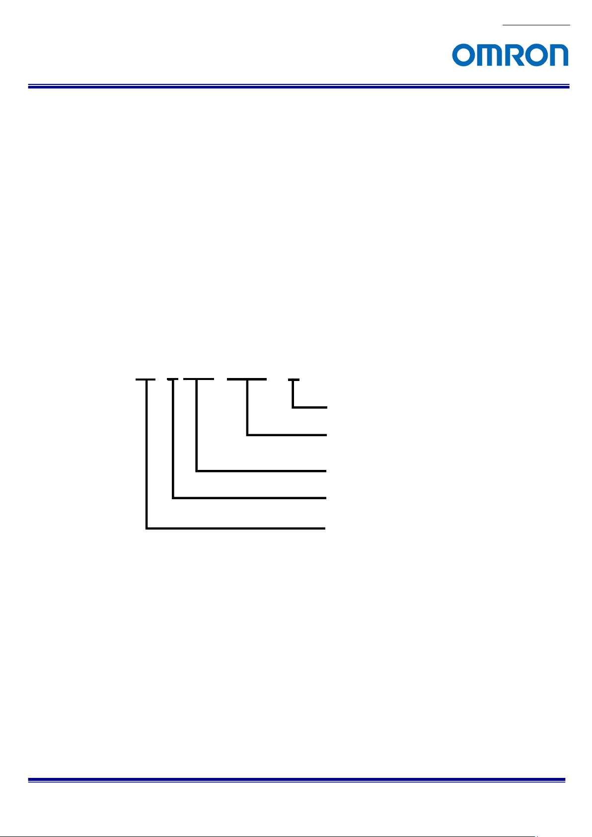
3.2 Product Number Naming Method
No.13S064-13
STC-CMx2MPOE-x
IR: Near IR Sensor
POE: PoE (Power over Ethernet GigE)
2M: 2M, 2/3” sensor
4M: 4M, 1” sensor
B: Monochrome
C: Color
Sensor Manufacture
CM: CMOSIS
STC-CMC2MPOE / STC-CMB2MPOE / STC-CMB2MPOE-IR /
STC-CMC4MPOE / STC-CMB4MPOE / STC-CMB4MPOE-IR Product Specifications and User’s Guide
8/55
Page 9

No.13S064-13
4 Specifications
4.1 Electronic Specifications
STC-CMB2MPOE / STC-CMC2MPOE
Model Number STC-CMB2MPOE STC-CMC2MPOE
Image Sensor 2/3" 2M Progressive Monochrome CMOS
(CMOSIS: CMV2000)
Shutter Type Global Shutter
Active Picture Elements 2,048 (H) x 1,088 (V)
Cell Size 5.5 (H) x 5.5 (V) µm
Sync Method
Maximum 8bits output
Frame Rate 10bits output 25 fps
(at Full
scanning)
Image Output Format
Noise
Level
Minimum Scene Illumination Less than 1 Lux at F1.2, 50 Hz
Exposure 8bits output
Time 10bits output
10bits Packed output
Gain Analog N/A
Digital
ROI
Multi ROIs N/A
Gamma
HDR Supoort
Binning
Decimation N/A
Flip Image N/A
Pixel Blemish Correction Up to 64 points
Auto Image Auto Exposure Support Support
Control Auto Gain (AGC) Support Support
Auto White Balance N/A Support
Operational Mode
Communication UART communication through Ethernet port
Interface IEEE802.3 (1000BASE-T)
Protocol GigE Vision 1.2 GenICam 2.0
I/O One opt-isolated input and two open collector outputs (+3.3 V)
Power Input Voltage +10.8 to +26.4 Vdc (IO Connector) or Power Over Ethernet (IEEE802.3af compliance)
10bits Packed output 34 fps
Mono8 / Mono10 / Mono10Packed BayerGB8 / BayerGB10 / BayerGB10Packed
8bits output Less than 2.5 Digits (Gain 0 dB)
10bits / 10bits Packed output
Horizontal: 8 to 2,048 pixels / Vertical: 4 to 1,088 lines (Default: 2,048 x 1,088)
Adjustable steps for image size: 8 pixels in horizontal direction / 2 lines in vertical direction
Adjustable steps for offset: 8 pixels in horizontal direction / 2 lines in vertical direction
Gamma 1.0 (Factory default) or uploadable gamma table (Default: 1)
Horizontal: 1/2, Vertical: 1/2 / Off
Consumption Less than 3.6 W
External trigger (Hardware / Software) / Free run
50 fps
Less than 15 Digits (Gain 0 dB)
24 µseconds to 20 seconds (Default: 24 µseconds)
x1 to x5 (Default: x1)
Edge preset trigger / Pulse width trigger / Free run
Default: Bold
2/3" 2M Progressive Color CMOS
(CMOSIS: CMV2000)
N/A
STC-CMC2MPOE / STC-CMB2MPOE / STC-CMB2MPOE-IR /
STC-CMC4MPOE / STC-CMB4MPOE / STC-CMB4MPOE-IR Product Specifications and User’s Guide
9/55
Page 10

No.13S064-13
STC-CMB4MPOE / STC-CMC4MPOE
Model Number STC-CMB4MPOE STC-CMC4MPOE
Image Sensor 1" 4M Progressive Monochrome CMOS
(CMOSIS: CMV2000)
Shutter Type Global Shutter
Active Picture Elements 2,048 (H) x 2,048 (V)
Cell Size 5.5 (H) x 5.5 (V) µm
Sync Method
Maximum 8bits output
Frame Rate 10bits output 13.5 fps
(at Full
scanning)
Image Output Format
Noise
Level
Minimum Scene Illumination Less than 1 Lux at F1.2, 50 Hz
Exposure 8bits output
Time 10bits output
10bits Packed output
Gain Analog N/A
Digital
ROI
Multi ROIs N/A
Gamma
HDR Support
Binning
Decimation N/A
Flip Image N/A
Pixel Blemish Correction Up to 64 points
Auto Image Auto Exposure Support Support
Control Auto Gain (AGC) Support Support
Auto White Balance N/A Support
Operational Mode
Communication UART communication through Ethernet port
Interface IEEE802.3 (1000BASE-T)
Protocol GigE Vision 1.2 GenICam 2.0
I/O One opt-isolated input and two open collector outputs (+3.3 V)
Power Input Voltage +10.8 to +26.4 Vdc (IO Connector) or Power Over Ethernet (IEEE802.3af compliance)
10bits Packed output 17.5 fps
Mono8 / Mono10 / Mono10Packed BayerGB8 / BayerGB10 / BayerGB10Packed
8bits output Less than 2.5 Digits (Gain 0 dB)
10bits / 10bits Packed output
Horizontal: 8 to 2,048 pixels / Vertical: 4 to 2,048 lines (Default: 2,048 x 2,048)
Adjustable steps for image size: 8 pixels in horizontal direction / 2 lines in vertical direction
Adjustable steps for offset: 8 pixels in horizontal direction / 2 lines in vertical direction
Gamma 1.0 (Factory default) or uploadable gamma table (Default: 1)
Horizontal: 1/2, Vertical: 1/2 / Off
Consumption Less than 3.6 W
External trigger (Hardware / Software) / Free run
25 fps
Less than 15 Digits (Gain 0 dB)
24 µseconds to 20 seconds (Default: 24 µseconds)
x1 to x5 (Default: x1)
Edge preset trigger / Pulse width trigger / Free run
1" 4M Progressive Color CMOS
(CMOSIS: CMV4000)
N/A
Default: Bold
STC-CMC2MPOE / STC-CMB2MPOE / STC-CMB2MPOE-IR /
STC-CMC4MPOE / STC-CMB4MPOE / STC-CMB4MPOE-IR Product Specifications and User’s Guide
10/55
Page 11

No.13S064-13
STC-CMB2MPOE-IR / STC-CMB4MPOE-IR
Model Number STC-CMB2MPOE-IR STC-CMB4MPOE-IR
Image Sensor 2/3" 2M Progressive Near IR CMOS
(CMOSIS: CMV2000)
Shutter Type Global Shutter
Active Picture Elements 2,048 (H) x 1,088 (V) 2,048 (H) x 2,048 (V)
Cell Size 5.5 (H) x 5.5 (V) µm
Sync Method
Maximum 8bits output
Frame Rate 10bits output 25 fps 13.5 fps
(at Full
scanning)
Image Output Format
Noise
Level
Minimum Scene Illumination Less than 1 Lux at F1.2, 50 Hz
Exposure 8bits output
Time 10bits output
10bits Packed output
Gain Analog N/A
Digital
ROI Horizontal: 8 to 2,048 pixels /
Multi ROIs N/A
Gamma
HDR Support
Binning
Decimation N/A
Flip Image N/A
Pixel Blemish Correction Up to 64 points
Auto Image Auto Exposure Support
Control Auto Gain (AGC) Support
Auto White Balance N/A
Operational Mode
Communication UART communication through Ethernet port
Interface IEEE802.3 (1000BASE-T)
Protocol GigE Vision 1.2 GenICam 2.0
I/O One opt-isolated input and two open collector outputs (+3.3 V)
Power Input Voltage +10.8 to +26.4 Vdc (IO Connector) or Power Over Ethernet (IEEE802.3af compliance)
10bits Packed output 34 fps 17.5 fps
8bits output Less than 2.5 Digits (Gain 0 dB)
10bits / 10bits Packed output
Vertical: 4 to 1,088 lines
(Default: 2,048 x 1,088)
Adjustable steps for image size: 8 pixels in horizontal direction / 2 lines in vertical direction
Adjustable steps for offset: 8 pixels in horizontal direction / 2 lines in vertical direction
Gamma 1.0 (Factory default) or uploadable gamma table (Default: 1)
Consumption Less than 3.6 W
External trigger (Hardware / Software) / Free run
50 fps 25 fps
Mono8 / Mono10 / Mono10Packed
Less than 15 Digits (Gain 0 dB)
24 µseconds to 20 seconds (Default: 24 µseconds)
x1 to x5 (Default: x1)
Horizontal: 1/2, Vertical: 1/2 / Off
Edge preset trigger / Pulse width trigger / Free run
1" 4M Progressive Near IR CMOS
(CMOSIS: CMV4000)
Horizontal: 8 to 2,048 pixels /
Vertical: 4 to 2,048 lines
(Default: 2,048 x 2,048)
Default: Bold
STC-CMC2MPOE / STC-CMB2MPOE / STC-CMB2MPOE-IR /
STC-CMC4MPOE / STC-CMB4MPOE / STC-CMB4MPOE-IR Product Specifications and User’s Guide
11/55
Page 12
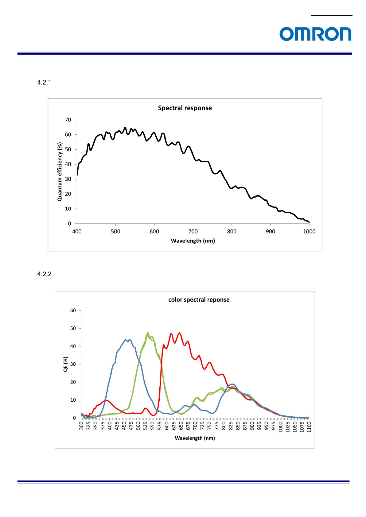
4.2 Spectral Sensitivity Characteristics
STC-CMB2MPOE / STC-CMB4MPOE
STC-CMC2MPOE / STC-CMC4MPOE
STC-CMC2MPOE / STC-CMB2MPOE / STC-CMB2MPOE-IR /
STC-CMC4MPOE / STC-CMB4MPOE / STC-CMB4MPOE-IR Product Specifications and User’s Guide
No.13S064-13
12/55
Page 13
No.13S064-13
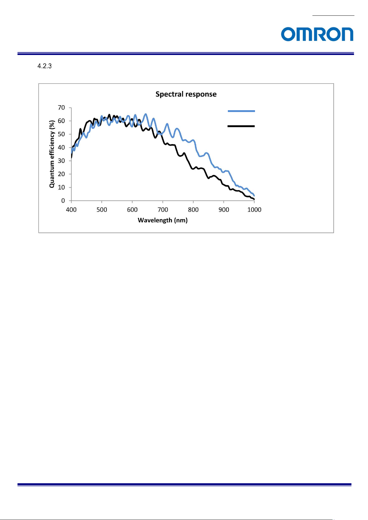
STC-CMB2MPOE-IR / STC-CMB4MPOE-IR (Near IR Model)
Near IR Model
Normal Model(Mono)
STC-CMC2MPOE / STC-CMB2MPOE / STC-CMB2MPOE-IR /
STC-CMC4MPOE / STC-CMB4MPOE / STC-CMB4MPOE-IR Product Specifications and User’s Guide
13/55
Page 14
No.13S064-13
4.3 Mechanical Specifications
Model Number STC-CMB2MPOE / STC-CMB4MPOE /
STC-CMB2MPOE-IR / STC-CMB4MPOE-IR
Dimensions 35 (W) x 35 (H) x 55.9 (D) mm (*1)
Optical Filter No Optical Filter No Optical Filter (*2)
Optical Center Accuracy Positional accuracy in Horizontal and Vertical directions: +/- 0.3 mm
Rotational accuracy of Horizontal and Vertical: +/- 2.0 deg.
Material Aluminum (AC)
Lens Mount C mount
Connectors RJ45 connector
Power- I/O connector: HR10A-7R-6PB (Hirose) or equivalent
Camera Mount Screws Two 1/4” Tripod screw holes (One on top and bottom plate)
Eight M4 screws holes (Four on top and bottom plate)
Weight Approximately 120 g
STC-CMC2MPOE / STC-CMC4MPOE
(*1) Excluding connectors
(*2) The color model with IR Cut Filter is optional mode. Please contact to sale representative.
4.4 Environmental Specifications
Model Number STC-CMB2MPOE / STC-CMB4MPOE /
STC-CMB2MPOE-IR / STC-CMB4MPOE-IR
Operational
Temperature / Humidity
Storage Temperature / Humidity
Vibration 20 Hz to 200 Hz to 20 Hz (5 min. / cycle), acceleration 10 G, XYZ 3 directions 30 min. each)
Shock Acceleration 38 G, half amplitude 6 mseconds, XYZ 3 directions 3 times each
Standard Compliancy EMS: EN61000-6-2, EMI: EN55011
RoHS RoHS Compliance
Minimum
Maximum (*1)
Environmental Humidity: 0 to 85 %RH (No condensation)
Camera housing temperature (top plate) shall not exceed +65 deg. C
(This corresponds to an environmental temperature of approximately +40 deg. C)
Environmental Humidity: 0 to 85 %RH (No condensation)
Environmental Temperature -5 deg. C,
Environmental Temperature: -30 to +65 deg. C,
STC-CMC2MPOE / STC-CMC4MPOE
(*1) When the camera using under the condition that exceeds +40 deg. C environmental temperature, please insure the
camera installs with the appropriate heat dissipation to keep the housing temperature less than +65 deg. C.
If camera has a mounted lens and a tripod with an aluminum plate, this could decrease the camera housing
temperature for heat dissipation.
Taking these steps will maintain the heat rating of the electronic components of the camera.
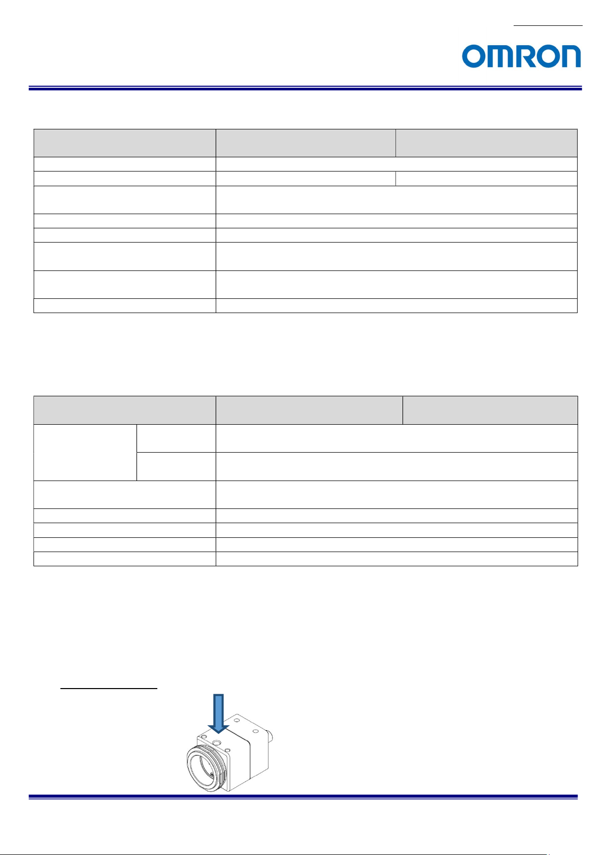
Upper side of camera
Measuring point
STC-CMC2MPOE / STC-CMB2MPOE / STC-CMB2MPOE-IR /
STC-CMC4MPOE / STC-CMB4MPOE / STC-CMB4MPOE-IR Product Specifications and User’s Guide
14/55
Page 15
5 Connector Specifications
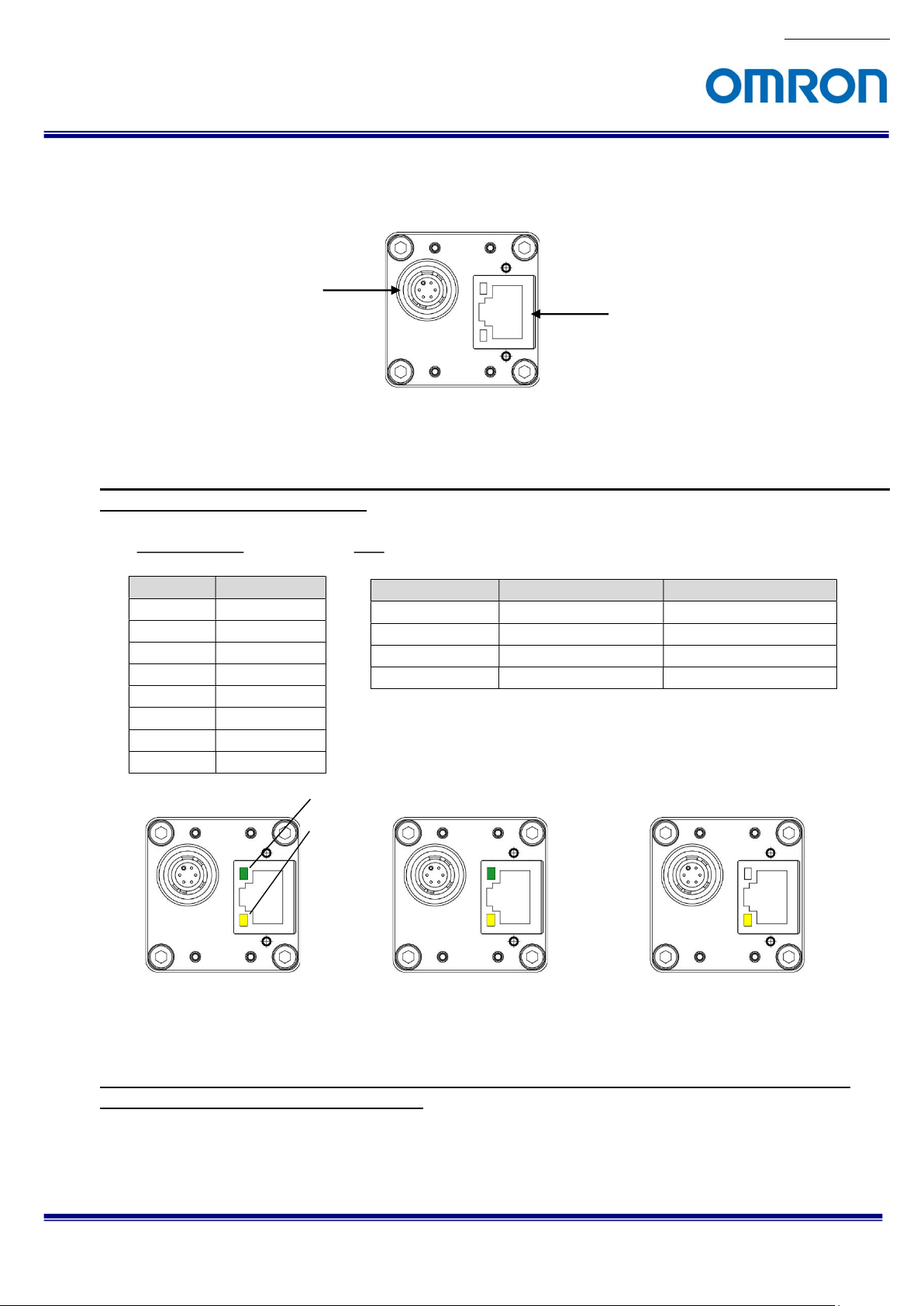
5.1 RJ45 Connector
This product is PoE compliant. Please supply power (+10.8 to +26.4 Vdc) through the power-I/O connector
when using non-PoE-compliant NIC.
Please use a 1GB supported NIC, Network Switcher and LAN cable. Check that the NIC and Network
Switcher being used is “1GB transferring”.
Power-I/O Connector
Pin Assignment LED
Pin No. Signal Name
1 TA+
2 TA3 TB+
4 TC+
5 TC6 TB7 TD+
8 TD-
Camera is powered-on
Green Light ON Yellow Light ON Power ON(1GB NIC)
Green Light OFF Yellow Light OFF Power ON(100MB NIC)
Green Light ON Yellow Light Blinking 1Gb Transferring
Light OFF Yellow Light Blinking 100 Mb Transferring
Green LED
Yellow LED
RJ45 Connector
Green LED Yellow LED Status
Green light: ON
Yellow light: Blinking
1 GB Transferring
Green light: OFF
Yellow light: Blinking
100 MB Transferring
No.13S064-13
STC-CMC2MPOE / STC-CMB2MPOE / STC-CMB2MPOE-IR /
STC-CMC4MPOE / STC-CMB4MPOE / STC-CMB4MPOE-IR Product Specifications and User’s Guide
15/55
Page 16
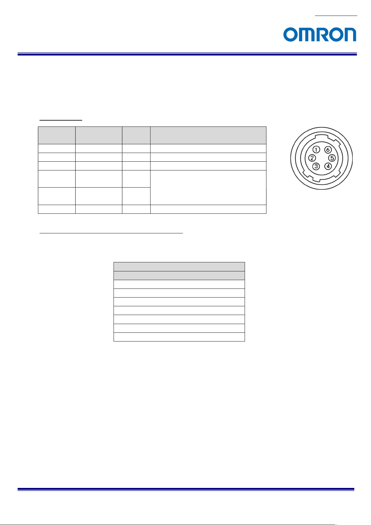
5.2 Power and Control Signal Connector
HR10A-7R-6PB (Hirose) or equivalent
This connector is for the power supply (12Vdc) and input /output signals.
Use HR10A-7P-6S (Hirose) or equivalent for the cable side.
Pin assignment
No.13S064-13
Pin No. Signal Name
1 GND IN 0 V
2 I/O-1 OUT +3.3 V Open Collector
3 I/O-2 OUT +3.3 V Open Collector
4
5
TRG_In-
(Opt. Isolated -)
TRG_In+
(Opt. Isolated +)
6 POWER IN IN +10.8 to +26.4 Vdc
Configuration of I/O-1(Pin No.2) and I/O-2(Pin No.3)
Output pin can be assigned through register setting or GenICam Command.
IN /
Voltage
OUT
IN
IN
Low: Smaller than +1.0 V
High: +3.0 to +26.4 V
* potential difference between TRG_Inand TRG_In+
GenICam command
I/O-1 (Pin No.2) / I/O-2 (Pin No.3)
1) FrameTriggerWait (initial setting for I/O-1)
2) UserOutput
3) ExposureActive (initial setting for I/O-2)
4) TriggerAuxiliary
5) TriggerInternal
6) SensorReadOut
7) StrobeSignal
STC-CMC2MPOE / STC-CMB2MPOE / STC-CMB2MPOE-IR /
STC-CMC4MPOE / STC-CMB4MPOE / STC-CMB4MPOE-IR Product Specifications and User’s Guide
16/55
Page 17

1) FrameTriggerWait
The user can check the camera condition (camera exposure and image output processing by the
trigger signal with this FrameTriggerWait signal).
This signal is LOW for the period from the trigger input signal to the image output.
2) UserOutput
The status of the UserOutput signal can change with the “UserOutputValue”.
3) ExposureActive
The user can check the exposure time with the ExposureActive signal.
4) TriggerAuxiliary
The TriggerAuxiliary signal is the input trigger signal.
5) TriggerInternal
The TriggerInternal signal is the input trigger signal with the trigger delay time.
6) SensorReadOut
The SensorReadOut signal is the FVAL signal, which is the image output period of the time.
7) StrobeSignal
The StrobeSignal signal is the strobe control signal.
No.13S064-13
STC-CMC2MPOE / STC-CMB2MPOE / STC-CMB2MPOE-IR /
STC-CMC4MPOE / STC-CMB4MPOE / STC-CMB4MPOE-IR Product Specifications and User’s Guide
17/55
Page 18

No.13S064-13
Equivalent Circuit for the Input Pin of the I/O Connector
STC-CMC2MPOE / STC-CMB2MPOE / STC-CMB2MPOE-IR /
STC-CMC4MPOE / STC-CMB4MPOE / STC-CMB4MPOE-IR Product Specifications and User’s Guide
18/55
Page 19

Typical Input Circuit
No.13S064-13
STC-CMC2MPOE / STC-CMB2MPOE / STC-CMB2MPOE-IR /
STC-CMC4MPOE / STC-CMB4MPOE / STC-CMB4MPOE-IR Product Specifications and User’s Guide
19/55
Page 20

Typical Output Circuit
STC-CMC2MPOE / STC-CMB2MPOE / STC-CMB2MPOE-IR /
STC-CMC4MPOE / STC-CMB4MPOE / STC-CMB4MPOE-IR Product Specifications and User’s Guide
Note:
Value of Vcc and
Pull up register can be set
within the spec of
transistor.
No.13S064-13
20/55
Page 21

Input and Output Signal Timing (Hardware Trigger)
Case of “External Hardware Trigger”, “Positive Edge Trigger”, “Edge Preset Exposure”,
Camera internal processing
External hardware
trigger
Photocoupler output
Filtering
Trigger delay
No.13S064-13
Up to 15us
For the signal duration, refer to another chapter "Exposure".
TriggerDelay on GenICam
For the signal duration, refer to another chapter "Exposure".
Exposure
Video output
Output Signal
FrameTriggerWait
ExposureActive
TriggerAuxiliary
TriggerInternal
SensorReadOut
StrobeSignal
ExposureTimeRaw on GenICam
StrobeSignalDelay on GenICam
STC-CMC2MPOE / STC-CMB2MPOE / STC-CMB2MPOE-IR /
STC-CMC4MPOE / STC-CMB4MPOE / STC-CMB4MPOE-IR Product Specifications and User’s Guide
StrobeSignalOnTime on GenICam
21/55
Page 22

Input and Output Signal Timing (Software Trigger)
Case of “Software Trigger”, “Positive Edge Trigger”, “Edge Preset Exposure”,
Camera internal processing
Software trigger,PLC
and Command
Trigger delay
Exposure
No.13S064-13
TriggerDelay on GenICam
For the signal duration, refer to another chapter "Exposure".
ExposureTimeRaw on GenICam
Video output
Output Signal
FrameTriggerWait
ExposureActive
TriggerAuxiliary
TriggerInternal
SensorReadOut
StrobeSignal
StrobeSignalDelay on GenICam
StrobeSignalOnTime on GenICam
STC-CMC2MPOE / STC-CMB2MPOE / STC-CMB2MPOE-IR /
STC-CMC4MPOE / STC-CMB4MPOE / STC-CMB4MPOE-IR Product Specifications and User’s Guide
22/55
Page 23

6 Dimensions
No.13S064-13
STC-CMC2MPOE / STC-CMB2MPOE / STC-CMB2MPOE-IR /
STC-CMC4MPOE / STC-CMB4MPOE / STC-CMB4MPOE-IR Product Specifications and User’s Guide
Unit:mm
23/55
Page 24

7 Sensor information
7.1 Pixel Transferring Image
STC-CMB2MPOE / STC-CMC4MPOE (Monochrome)
STC-CMB2MPOE-IR / STC-CMB4MPOE-IR (Near IR)
STC-CMC2MPOE / STC-CMC4MPOE (Color)
STC-CMC2MPOE / STC-CMB2MPOE / STC-CMB2MPOE-IR /
STC-CMC4MPOE / STC-CMB4MPOE / STC-CMB4MPOE-IR Product Specifications and User’s Guide
Pixel1 of
Data
Pixel11 of
Data
Pixe21 of
Data
Pixel2 of
Data
Pixel (n) of Data: nth pixel being transferred
Pixel12 of
Data
Pixel22 of
Data
Pixel (m, n) of Data: nth pixel of the mth line being transferred
No.13S064-13
24/55
Page 25

8 Camera Operational Modes
8.1 Normal Mode
Trigger Input (Positive)
S e n s o r
E x p o s u r e
I m a g e o u t
8.2 Pulse width trigger mode
In this trigger mode with positive polarity, the camera exposure starts at the rising edge of the trigger pulse and
stops at the falling edge of the trigger pulse. Therefore, if positive polarity exposure is selected, the exposure
periods are the high states of the trigger pulse.
Timing
Exposure Time
Image Out
Note 1: The exposure time is set by active pulse duration of trigger signal.
No.13S064-13
E x p o s u r e
T i m e
STC-CMC2MPOE / STC-CMB2MPOE / STC-CMB2MPOE-IR /
STC-CMC4MPOE / STC-CMB4MPOE / STC-CMB4MPOE-IR Product Specifications and User’s Guide
25/55
Page 26

No.13S064-13
Exposure Timing with the Positive Polarity Trigger Signal
Input Trigger signal
T1
Trigger signal
(With Photocoupler delay
Less than
15 useco nds
T1
Filtering *Note.1
30 CLK
Exposure time
75 CLK
Exposure time:: T1' = T1 + 127 CLK
Note 1: The trigger signal will be removed by the filtering if the pulse width of the input trigger signal is less than 30 CLK.
Please input a trigger signal with more than 31 CLK pulse width.
Note 2: The exposure will start 105 CLK after the rising edge of the trigger signal.
Exposure Timing with the Negative Polarity Trigger Signal
Input Trigger signal
T1
Trigger signal
(With Photocoupler delay
Less than
60 useco nds
T1
Filtering *Note.1
30 CLK
Exposure time
75 CLK
Exposure time: T1' = T1 + 127 C LK
Note 1: The trigger signal will be removed by the filtering if the pulse width of the input trigger signal is less than 30 CLK.
Please input a trigger signal with more than 31 CLK pulse width.
Note 2: The exposure will start 105 CLK after the rising edge of the trigger signal.
STC-CMC2MPOE / STC-CMB2MPOE / STC-CMB2MPOE-IR /
STC-CMC4MPOE / STC-CMB4MPOE / STC-CMB4MPOE-IR Product Specifications and User’s Guide
26/55
Page 27

No.13S064-13
8.3 Edge Preset Trigger Mode
In this “edge preset trigger mode”, the camera exposure starts at the rising edge of the trigger signal like the “pulse
width trigger mode” in the previous sections. However, in this mode, the exposure duration time is based on the preset
value stored by the by the camera setting communication.
Timing
Trigger signal
(Rising e dge)
Sensor
exposure
※Note1
Exposure
time
Image ou t
Note 1: The exposure time is set by preset electronic shutter speed.
STC-CMC2MPOE / STC-CMB2MPOE / STC-CMB2MPOE-IR /
STC-CMC4MPOE / STC-CMB4MPOE / STC-CMB4MPOE-IR Product Specifications and User’s Guide
27/55
Page 28

No.13S064-13
Exposure Timing with the Positive Polarity Trigger Signal
Input Trigger signal
Trigger signal
(With Photocoupler delay
Less than
15useco nds
Filtering *Note.1
30 CLK
Exposure time
75 CLK
Exposure tim: T1' = Pre set exposure time
Note 1: The trigger signal will be removed by the filtering if the pulse width of the input trigger signal is less than 30 CLK.
Please input a trigger signal with more than 31 CLK pulse width.
Note 2: The exposure will start 105 CLK after the rising edge of the trigger signal.
Exposure Timing with the Negative Polarity Trigger signal
Input Trigger signal
Trigger signal
(With Photocoupler delay
Less than
60 useconds
Filtering *Note.1
30 CLK
Exposure time
75 CLK
Exposure tim: T1' = Preset exposure time
Note 1: The trigger signal will be removed by the filtering if the pulse width of the input trigger signal is less than 30 CLK.
Please input a trigger signal with more than 31 CLK pulse width.
Note 2: The exposure will start 105 CLK after the rising edge of the trigger signal.
STC-CMC2MPOE / STC-CMB2MPOE / STC-CMB2MPOE-IR /
STC-CMC4MPOE / STC-CMB4MPOE / STC-CMB4MPOE-IR Product Specifications and User’s Guide
28/55
Page 29

8.4 Edge Preset Trigger Mode (Trigger Input While the Image Is Out)
In this trigger mode, the camera exposure starts at the rising edge of the trigger pulse.
If trigger signal input is required while the image is out, then it is necessary to disable the trigger signal mask with
the communication.
To avoid generating additional noise on the image, it is necessary to set the “H reset” at the exposure start mode.
Timing
Trigger Signal
(Positive)
Sensor
Exposure
Exposure
TIme
Image ou t
Note 1: The exposure time is set by the preset electronic shutter speed.
No.13S064-13
STC-CMC2MPOE / STC-CMB2MPOE / STC-CMB2MPOE-IR /
STC-CMC4MPOE / STC-CMB4MPOE / STC-CMB4MPOE-IR Product Specifications and User’s Guide
29/55
Page 30

Width
OffsetX
OffsetY
ROI area
9 Camera Functions
9.1 ROI (Region of Interest)
The specified area of the image can output from the camera with ROI function.
The frame rate is increased when the height is reduced.
The frame rate does not increase when the width is reduced.
ROI (1 region)
GenICamparamters
Width Integer type Width of the output image (pixels)
(Width + OffsetX) should not exceeded maximum width.
Height Integer type Height of the output image (lines)
(Height + OffsetY) should not exceeded maximum height.
OffsetX Integer type Horizontal (pixel) offset
Default: 0, Adjustable steps: 8 pixels
OffsetY Integer type Vertical (line) offset
Default: 0,
Adjustable steps: 2 liens
The ROI area settings are below:
No.13S064-13
Height
STC-CMC2MPOE / STC-CMB2MPOE / STC-CMB2MPOE-IR /
STC-CMC4MPOE / STC-CMB4MPOE / STC-CMB4MPOE-IR Product Specifications and User’s Guide
30/55
Page 31

Width / Height setting range
STC-CMB2MPOE
Width Range 8 to 2,048 pixels 8 to 2,048 pixels
Default 2,048 2,048
Adjustment steps 8 pixels 8 pixels
Height Range 4 to 1,088 lines 4 to 2,048 lines
Default 1,088 lines 2,048 lines
Adjustment steps 2 lines 2 lines
STC-CMC2MPOE
STC-CMB2MPOE-IR
No.13S064-13
STC-CMB4MPOE
STC-CMC4MPOE
STC-CMB4MPOE-IR
STC-CMC2MPOE / STC-CMB2MPOE / STC-CMB2MPOE-IR /
STC-CMC4MPOE / STC-CMB4MPOE / STC-CMB4MPOE-IR Product Specifications and User’s Guide
31/55
Page 32

9.2 Pixel Format
The image format from camera can be set on the Pixel Format.
GenICam Parameters
PixelFormat IEnumeration Type Pixel Format
The following chart shows the available Pixel Formats on the camera:
Output Bit Pixel Format
Monochrome Camera Color Camera
8bits Mono8 BayerRG8
10bits Mono10 BayerRG10
10bits Packed Mono10Packed BayerRG10Packed
Each format specified on GenICam PFNC (Pixel Format Naming Convention).
9.3 Binning
Binning is add and average beside pixels into one pixel.
The pixel data inside of red square add or average as one pixel.
Binning
X(Off), Y(Off)
Binning X(Off), Y(On)
No.13S064-13
Binning X(On), Y(Off) Binning X(On), Y(On)
GenICamParameters
BinningHorizontal Integer Type Sets Binning on Horizontal direction
1: Disable Binning 2: Binning 2 Pixel
BinningVertical Integer Type Sets Binning on Vertical direction
1: Disable Binning 2: Binning 2 Pixel
STC-CMC2MPOE / STC-CMB2MPOE / STC-CMB2MPOE-IR /
STC-CMC4MPOE / STC-CMB4MPOE / STC-CMB4MPOE-IR Product Specifications and User’s Guide
32/55
Page 33

9.4 Gain
The analog gain and the digital gain are available for the gain control.
Digital gain
This parametersets the digital gain.
GenICam parameter
DigitalGain Integer type Digital gain.
Range: 0 to 511, Default: 0
Digital gain formula
Gain (xtimes) = 1+ (DigitalGain / 64)
9.5 Black level
This parameter sets the black level (the clamp level for the black signal).
The bottom of the signal is clamped at this setting level. The signal does not become below this level.
GenICam parameter
BlackLevel Float type Black level.
Range: 0 to 31, Default: 10
Black level formula
At 10bits output: Black level (grayscale) = BlackLevel
At 8bits output: Black level (grayscale) = BlackLevel / 4
No.13S064-13
STC-CMC2MPOE / STC-CMB2MPOE / STC-CMB2MPOE-IR /
STC-CMC4MPOE / STC-CMB4MPOE / STC-CMB4MPOE-IR Product Specifications and User’s Guide
33/55
Page 34

No.13S064-13
9.6 ALC (Auto Light Control)
ALC function has two control methods, which is AGC (Auto Gain Control) and the auto shutter. The AGC and the auto
shutter sets up individually.
The camera parameters are adjusted to the brightness of the image is maintained with the target brightness
automatically with the ALC function.
GenICam parameters (for AGC and auto shutter)
TargetBrightness Integer type Target brightness.
Range: 0 to 255, Default: 128
ACL_Peak_Average Integertype Importance ratio for the brightness peak at ALC control.
Range: 0 to 255, Default: 0
ALCWeight1
ALCWeight2
ALCWeight3
Integer type Weight.
Range: 0 to 15, Default: 1 * Set 10 on ALCWeight5 only
Sets the weight for each weight area.
ALCWeight4
ALCWeight5
ALCWeight6
ALCWeight7
ALCWeight8
ALCWeight9
ALCWindowV1
ALCWindowV2
ALCWindowV3
ALCWindowV4
Integer type Vertical positions for the frame of the weight area.
STC-CMB2MPOE
STC-CMC2MPOE
STC-CMB2MPOE-IR
STC-CMB4MPOE
STC-CMC4MPOE
STC-CMB4MPOE-IR
Range 0 to 1,087 0 to 2,047
ALCWindowH1
ALCWindowH2
ALCWindowH3
ALCWindowH4
Default V1 (32), V2 (394),
V3 (694), V4 (1,056)
Integer type Horizontal positions for the frame of the weight area.
STC-CMB2MPOE
STC-CMC2MPOE
STC-CMB2MPOE-IR
V1 (32), V2 (714),
V3 (1,334), V4 (2,016)
STC-CMB4MPOE
STC-CMC4MPOE
STC-CMB4MPOE-IR
Range 0 to 2,047 0 to 2,047
Default H1 (32), H2 (718),
H3 (1,330), H4 (2,012)
H1 (32), H2 (718),
H3 (1,330), H4 (2,012)
Target brightness (TargetBrightness) formula
At 10bits output: Target brightness (grayscale) = TargetBrightness x 4
At 8bits output: Target brightness (grayscale) = TargetBrightness
About the importance ratio for the brightens peak at ALC control (ACL_Peak_Average)
When 0 sets, Average: 100 %, Peak: 0 %. The ALC control with the brightness average.
When 255 sets, Average: 0 %, Peak: 100 %. The ALC control with the brightness peak.
When 128 sets, Average: 50 %, Peak: 50 %.
STC-CMC2MPOE / STC-CMB2MPOE / STC-CMB2MPOE-IR /
STC-CMC4MPOE / STC-CMB4MPOE / STC-CMB4MPOE-IR Product Specifications and User’s Guide
34/55
Page 35

No.13S064-13
ALCWindowV1
ALCWindowV2
ALCWindowV3
ALCWindowV4
ALCWindowH4
ALCWindowH3
ALCWindowH2
ALCWindowH1
Area1
Area2
Area3
Area4
Area5
Area6
Area7
A
rea8
Area9
ALC control method
The ALC control with the weight area1 to 9.
The weight area setting parameters are in below:
The brightness average and peak calculate for each weight area.
The target brightness comparison value calculates with “ALC_Peak_Average”, the brightness average and peak then
compare with the target brightness to define the necessary brightness control (to dark or to bright).
The brightness of the image maintains to the “TargetBrightness” with the AGC and the auto shutter functions.
If AGC and the auto shutter are ON for the ALC control, the auto shutter function maintains the brightness first. The
AGC function maintains the brightness if the brightness cannot maintain to the TargetBrightness with the auto shutter.
AGC (Auto Gain Contorl)
The brightness of the image maintains to the target brightness with the gain automatically.
If the brightness of the image is the darker than the target brightness, the gain increases up to AGCRange.
If the brightness of the image is the brighter than the target brightness, the gain decreases.
GenICam parameters
GainAuto Enumeration type AGC ON / OFF selection
AGCRange Integer type Maximum gain.
Selection: ON (Continuous) or OFF (Off). Default: OFF
Range: 0 to 255, Default: 255
This is the maximum gain for AGC.
STC-CMC2MPOE / STC-CMB2MPOE / STC-CMB2MPOE-IR /
STC-CMC4MPOE / STC-CMB4MPOE / STC-CMB4MPOE-IR Product Specifications and User’s Guide
35/55
Page 36

Auto shutter
The brightness of the image maintains to the target brightness with the shutter automatically.
If the brightness of the image is the darker than the target brightness, the exposure time extends up to
Max_ShutterTime.
If the brightness of the image is the brighter than the target brightness, the exposure time becomes shorter up to
Min_ShutterTime.
GenICam parameters
ExposureAuto Enumeration
type
Min_ShutterTime Integer type Minimum exposure time (µsecond).
Max_ShutterTime Integer type Maximum exposure time (µsecond).
ALC settings procedure
ALC settings procedure
1. Sets ALCWeight1 to 9.
2. Sets ALCWindowV1 to 4.
3. Sets ALCWindowH1 to 4.
4. Sets TargetBrightness.
5. Sets ACL_Peak_Average.
6. Sets AGCRange if AGC is using.
7. Sets Min_ShutterTime, if the auto shutter is using.
8. Sets Max_ShutterTime, if the auto shutter is using.
9. Sets “Continuous” at GainAuto, if AGC is using.
10. Sets “Continuous” at ExposureAuto, if the auto shutter is using.
Auto shutter ON / OFF selection
ON (Continuous), OFF (Off). Default: OFF
Range: 10 to 16,777,215 Default: 10
Range: 10 to 16,777,215 Default: 19094
No.13S064-13
STC-CMC2MPOE / STC-CMB2MPOE / STC-CMB2MPOE-IR /
STC-CMC4MPOE / STC-CMB4MPOE / STC-CMB4MPOE-IR Product Specifications and User’s Guide
36/55
Page 37

9.7 White balance (Only available for the color cameras)
The color compensates with the gain adjustment each color.
The gain for each color has to adjust with the flat white target to each color has the same brightness.
The white balance control methods are the listed in the below:
OFF
Auto white balance
Push to set white balance
Preset1 to 3
White balance control methods
GenICam parameters
BalanceWhiteAuto Enumeration
type
BalanceRatioSelector Enumeration
type
BalanceRatio Float type Color gain setting for the color selects at BalanceRatioSelector
YThreshold Integer type The brightness threshold to use the pixel for the auto white
BalanceRatio_R_Once Integer type R white balance gain for OFF and push to set white balance.
BalanceRatio_Gr_Once Integer type GR white balance gain for OFF and push to set white balance.
BalanceRatio_B_Once Integer type R white balance gain for OFF and push to set white balance.
BalanceRatio_Gb_Once Integer type Gb white balance gain for OFF and push to set white balance.
BalanceRatio_R_Preset1 Integer type R white balance gain for preset1.
BalanceRatio_Gr_Preset1 Integer type Gr white balance gain for preset1.
BalanceRatio_B_Preset1 Integer type B white balance gain for preset1.
BalanceRatio_Gb_Preset1 Integer type Gb white balance gain for preset1.
BalanceRatio_R_Preset2 Integer type R white balance gain for preset2.
BalanceRatio_Gr_Preset2 Integer type Gr white balance gain for preset2.
BalanceRatio_B_Preset2 Integer type B white balance gain for preset2.
BalanceRatio_Gb_Preset2 Integer type Gr white balance gain for preset2.
White balance control method selection. Default: off
White balance control target color selection.
balance control.
Default: 0,Range: 0 to 4,095
Default: 0
Default: 0
Default: 0
Default: 0
Default: 0
Default: 0
Default: 0
Default: 0
Default: 0
Default: 0
Default: 0
Default: 0
No.13S064-13
STC-CMC2MPOE / STC-CMB2MPOE / STC-CMB2MPOE-IR /
STC-CMC4MPOE / STC-CMB4MPOE / STC-CMB4MPOE-IR Product Specifications and User’s Guide
37/55
Page 38

No.13S064-13
GenICam parameters
BalanceRatio_R_Preset3 Integer type R white balance gain for preset3.
Default: 0
BalanceRatio_Gr_Preset3 Integer type Gr white balance gain for preset3.
Default: 0
BalanceRatio_B_Preset3 Integer type B white balance gain for preset3.
Default: 0
BalanceRatio_Gb_Preset3 Integer type Gb white balance gain for preset3.
Default: 0
OFF
The white balance with BalanceRatio_X_Once (X: R, Gr, B or Gb)
If the white balance process is not necessary, please sets 0 for BalanceRatio_X_Once (X: R, Gr, B orGb)
White balance “OFF” setting procedure
1. Sets Off at BalanceWhiteAuto.
Auto white balance
The optimized white balance gain calculates each frame for the auto white balance.
Auto white balance setting procedure
1. Sets Continuous at BalanceWhiteAuto.
Push to set white balance
The white balance gain adjusts once after select this white balance then set to Balance_X_Once (X: R, Gr, B or Gb)
Sets OFF at BalanceWhiteAuto automatically after set Balance_X_Once.
Push to set white balance setting procedure
1. Sets the flat white target.
2. Sets Once at BalanceWhiteAuto.
STC-CMC2MPOE / STC-CMB2MPOE / STC-CMB2MPOE-IR /
STC-CMC4MPOE / STC-CMB4MPOE / STC-CMB4MPOE-IR Product Specifications and User’s Guide
38/55
Page 39

No.13S064-13
Preset white balance1 to 3
The camera has three preset manual white balance.
Presets saving area
Preset1: BalanceRatio_R_Preset1,BalanceRatio_Gr_Preset1,
BalanceRatio_B_Preset1,BalanceRatio_Gb_Preset1
Preset2: BalanceRatio_R_Preset2,BalanceRatio_Gr_Preset2,
BalanceRatio_B_Preset2,BalanceRatio_Gb_Preset2
Preset3: BalanceRatio_R_Preset3,BalanceRatio_Gr_Preset3,
BalanceRatio_B_Preset3,BalanceRatio_Gb_Preset3
Preset white balance setting procedure
1. Sets the white balance gain for the preset1, 2 or 3. (X: 1 to 3)
(BalanceRatio_R_PresetX, BalanceRatio_Gr_PresetX,BalanceRatio_B_PresetX,BalanceRatio_Gb_PresetX)
2. Sets PresetX (X: 1 to 3) at BalanceWhiteAuto.
STC-CMC2MPOE / STC-CMB2MPOE / STC-CMB2MPOE-IR /
STC-CMC4MPOE / STC-CMB4MPOE / STC-CMB4MPOE-IR Product Specifications and User’s Guide
39/55
Page 40

WB_WindowV1
WB_WindowV2
WB_WindowH2
WB_WindowH1
White balance calculate area setting
The white balance gain calculation area is changeable.
GenICam parameters
WB_WindowMode Enumeration
type
WB_WindowV1
Integer type Vertical frame position for the specified area.
WB_WindowV2
White balance gain calculation area selection
Full screen (Off), Specified area (On). Default: Full screen
STC-CMC2MPOE STC-CMC4MPOE
範囲 0 to 1,087 0 to 2,047
初期値 V1 (0), V2 (1,087) V1 (0), V2 (2,047)
WB_WindowH1
WB_WindowH2
Integer type Horizontal frame position for the specified area.
STC-CMC2MPOE STC-CMC4MPOE
範囲 0 to 2,047 0 to 2,047
初期値 H1 (0), H2 (2,047) H1 (0), H2 (2,047)
The brightness threshold for the white balance gain calculate pixel (YThreshold)
Threshold (grayscale) =YThreshold
12bits process in the camera.
The white balance calculation area settings are below:
No.13S064-13
calculation area
STC-CMC2MPOE / STC-CMB2MPOE / STC-CMB2MPOE-IR /
STC-CMC4MPOE / STC-CMB4MPOE / STC-CMB4MPOE-IR Product Specifications and User’s Guide
White balance gain
40/55
Page 41

No.13S064-13
9.8 Gamma correction
The gamma correction is the gamma = 1.0 or the gamma table control.
GenICam parameters
GammaMode Enumeration
type
ReloadGammaData Command type Gamma table loading from ROM to RAM
Gamma table loading procedure (ReloadGammaData)
1. Executes ReloadGammaData.
Gamma table writing
It is necessary to use the virtual com port communication (eBUS SDK: PvSerialPort class) to write the gamma table to
the camera. The gamma table cannot write the camera with GenICam parameter.
Please refer the other document for the details of the gamma table writing.
Gamma correction selection
Gamma = 1.0 (Off), Gamm table control (On). Default: Gamma = 1.0
STC-CMC2MPOE / STC-CMB2MPOE / STC-CMB2MPOE-IR /
STC-CMC4MPOE / STC-CMB4MPOE / STC-CMB4MPOE-IR Product Specifications and User’s Guide
41/55
Page 42

Selector
9.9 Save and load the camera setting data
The camera has the camera setting including the factory default, load function.
The camera has below two camera settings.
Default: The factory default settings (This setting cannot change)
User Set X: Over writeable camera settings (X: 0 to 7)
These camera settings load from ROM to the register in the RAM on the camera and camera settings save to ROM.
The camera settings saving and loading is controllable with Parameters (User Set Selector, User Set Default), and
commands (UserSetLoad, UserSetSave) in UserSetControl category of GenICam.
The details of the parameters and the functions are in the table below:
GenICam Parameters
UserSetSelector IEnumeration Type Select “Default” or ”UserSetX”
UserSetLoad or UserSetSave process for the selected settings.
UserSetLoad ICommand Type The camera settings load from ROM to the register in RAM.
UserSetSave ICommand Type The camera settings at the register in RAM save to ROM.
UserSetDefault IEnumeration Type Select which settings (“Default or UserSet X) load automatically when the
camera power is on. This selection saves automatically.
Saving the Camera Settings
Camera
Setting
UserSetSelector
ROM
UserSetX
ROM
Default
When UserSetSave is executing,
the camera settings at the register in RAM
are saved to the ROM that is selected at
UserSetSelector.
Caution:
UserSetSave cannot execute when “Default”
was selected at “UserSet Selector”
Setting Procedure
1. Selects “UserSetX” at “UserSetSelector”
2. Execute “UserSetSave”
No.13S064-13
STC-CMC2MPOE / STC-CMB2MPOE / STC-CMB2MPOE-IR /
STC-CMC4MPOE / STC-CMB4MPOE / STC-CMB4MPOE-IR Product Specifications and User’s Guide
42/55
Page 43

No.13S064-13
Selector
Selector
Loading Camera Settings
ROM
UserSetX
Camera
Setting
ROM
Default
UserSetSelector
Setting Procedure
1. Select “UserSetX” (or Default) at “UserSetSelector”
2. Execute “UserSetLoad”
Loading Camera Settings when the Camera Power is on
ROM
UserSetX
Camera
Setting
ROM
Default
UserSetSelector
Setting Procedure
1. Set “UserSetX” or “Default” at “UserSetDefault”
Camera Settings Initialization
Please follow the below procedure for the camera settings put back to the factory default settings.
Setting Procedure
1. Selects “Default” at “UserSetSelector”.
2. Executes “UserSetLoad”.
3. Select “UserSet1” at “UserSetSelector”.
4. Executes “UserSetSave”.
When UserSetLoad is executing,
the camera settings load from the selected
ROM that was selected at “UserSetSelector”
to the register at RAM.
When the camera power is on,
the camera settings load from the selected
ROM that was selected at “UserSetDefault”
to the register at RAM.
STC-CMC2MPOE / STC-CMB2MPOE / STC-CMB2MPOE-IR /
STC-CMC4MPOE / STC-CMB4MPOE / STC-CMB4MPOE-IR Product Specifications and User’s Guide
43/55
Page 44

9.10 Trigger
No.13S064-13
The description of trigger type and characteristic, please refer to the chapter “Image acquisition and Camera
Mode”.
Trigger Signal Processing Process
External Hardware Trigger or Software Trigger input the camera’s internal process as follows.
Switching Trigger can be done through register access or GenICam commands
Switching point 1: Switch to Hardware Trigger and Software Trigger
TriggerSource = Software on GenICam
TriggerSource = Hardware on GenICam
TriggerSource = Line0 on GenICam
STC-CMC2MPOE / STC-CMB2MPOE / STC-CMB2MPOE-IR /
STC-CMC4MPOE / STC-CMB4MPOE / STC-CMB4MPOE-IR Product Specifications and User’s Guide
44/55
Page 45

9.11 The camera settings (GenICam parameters) control with SDK
GenICam parameters are controllable with the eBUS SDK.
Please refer eBUS SDK API help file for the details.
Integer type parameter control
Integer type parameter such as “Width” control.
e.g. Width writing
[C++] PvDevice.GetGenParameters()->SetIntegerValue(“Width”, 256);
[C#】 PvDevice.GenParameters.SetIntegerValue(“Width”, 256);
e.g. Width reading
[C++] PvDevice.GetGenParameters()->GetIntegerValue(“Width”, &intValue);
[C#] intValue = PvDevice.GenParameters.GetIntegerValue(“Width”);
Float type parameter control
Float type parameter such as “AcquisitionFrameRate” control.
e.g. AcquisitionFrameRate writing
[C++] PvDevice.GetGenParameters()->SetFloatValue(“AcquisitionFrameRate”, 33.3);
[C#] PvDevice.GenParameters.SetFloatValue(“AcquisitionFrameRate”, 33.3);
e.g. AcquisitionFrameRate reading
[C++] PvDevice.GetGenParameters()->GetFloatValue(“AcquisitionFrameRate”, &doubleValue);
[C#] doubleValue = PvDevice.GenParameters.GetFloatValue(“AcquisitionFrameRate”);
Enumeration type parameter control
Enumeration type parameter such as “BalanceWhiteAuto” control.
e.g. BalanceWhiteAuto writing
[C++] PvDevice.GetGenParameters()->SetEnumValue(“BalanceWhiteAuto”, “Continuous”);
[C#] PvDevice.GenParameters.SetEnumValue(“BalanceWhiteAuto”, “Continuous” );
e.g. BalanceWhiteAuto reading
[C++] PvDevice.GetGenParameters()->GetEnumValue(“BalanceWhiteAuto”, &PvStringValue);
[C#] stringValue = PvDevice.GenParameters.GetEnumValueAsString(“BalanceWhiteAuto”);
No.13S064-13
STC-CMC2MPOE / STC-CMB2MPOE / STC-CMB2MPOE-IR /
STC-CMC4MPOE / STC-CMB4MPOE / STC-CMB4MPOE-IR Product Specifications and User’s Guide
45/55
Page 46

String type paramter control
String type parameter such as “DeviceModelName” control.
e.g.DeviceModelName writing (DeviceModelName cannot overwrite)
[C++] PvDevice.GetGenParameters()->SetString(“DeviceModelName”, “STC-SB33POE”);
[C#] PvDevice.GenParameters.SetStringValue(“DeviceModelName”, “STC-SB33POE”);
e.g. DeviceModelName reading
[C++] PvDevice.GetGenParameters()->GetString(“DeviceModelName”, &PvStringValue);
[C#] stringValue = PvDevice.GenParameters.GetStringValue(“DeviceModelName”);
Boolean type parameter control
Boolean type parameter such as “LineInverter0” control.
e.g. LineInverter0 writing
[C++] PvDevice.GetGenParameters()->SetBooleanValue(“LineInverter0”, true);
[C#] PvDevice.GenParameters.SetBooleanValue(“LineInverter0”, true);
e.g. LineInverter0 reading
[C++] PvDevice.GetGenParameters()->GetBooleanValue(“LineInverter0”, &boolValue);
[C#] boolValue = PvDevice.GenParameters. GetBooleanValue(“LineInverter”);
Command type paramter control
Command type parameter such as “TriggerSoftware”
e.g. TriggerSoftware generating
[C++] PvDevice.GetGenParameters()->ExecuteCommand(“TriggerSoftware”);
[C#] PvDevice.GenParameters.ExexuteCommand(“TriggerSoftware”);
No.13S064-13
STC-CMC2MPOE / STC-CMB2MPOE / STC-CMB2MPOE-IR /
STC-CMC4MPOE / STC-CMB4MPOE / STC-CMB4MPOE-IR Product Specifications and User’s Guide
46/55
Page 47

No.13S064-13
9.12 GenICam Command List
DeviceControl
Name Description
DeviceVendorName Name of the manufacturer of the device.
DeviceModelName Model of the device.
DeviceManufacturerInfo Manufacturer information about the device.
DeviceVersion Version of the device.
DeviceID Device’s serial number.
DeviceUserID User-programmable device identifier.
DeviceScanType Scan type of the sensor of the device.
DeviceTemperature Device temperature in degrees Celsius ©.
DeviceReset Reset the device to its power up state.
ImageFormatControl
Name Description
SensorDigitizationTaps Number of digitized samples outputted simultaneously by the camera A/D conversion
stage.
Width Width of the image provided by the device (in pixels).
Height Height of the image provided by the device (in pixels).
SensorShutterMode Sets the shutter mode of the device.
DecimationHorizontal Horizontal sub-sampling of the image. This reduces the horizontal resolution (width) of
the image by the specified horizontal decimation factor.
DecimationVertical Vertical sub-sampling of the image. This reduces the vertical resolution (height) of the
image by the specified vertical decimation factor.
PixelFormat Format of the pixels provided by the device. It represents all the information provided by
PixelCoding, PixelSize, PixelColorFilter combined in a single feature.
PixelCoding Coding of the pixels in the image, Raw gives the data in the native format of the sensor.
PixelSize Total size in bits of a pixel of the image.
PixelColorFilter Type of color filter that is applied to the image.
TestImageSelector Selects the type of test image that is sent by the camera.
OffsetX Horizontal offset from the origin to the region of interest (in pixels).
OffsetY Vertical offset from the origin to the region of interest (in pixels).
STC-CMC2MPOE / STC-CMB2MPOE / STC-CMB2MPOE-IR /
STC-CMC4MPOE / STC-CMB4MPOE / STC-CMB4MPOE-IR Product Specifications and User’s Guide
47/55
Page 48

No.13S064-13
AcquisitionControl
Name Description
AcquisitionMode Sets the acquisition mode of the device. It defines mainly the number of frames to
capture during an acquisition and the way the acquisition stops.
AcquisitionStart Starts the Acquisition of the device. The number of frames captured is specified by
AcquisitionMode.
AcquisitionStop Stops the Acquisition of the device at the end of the current Frame. It is mainly used
when AcquisitionMode is Continuous but can be used in any acquisition mode.
AcquisitionFrameCount Number of frames to acquire in MultiFrame Acquisition mode.
AcquisitionFrameRate Controls the acquisition rate (in Hertz) at which the frames are captured.
TriggerSelector Selects the type of trigger to configure.
TriggerMode Controls if the selected trigger is active.
TriggerSoftware Generates an internal trigger. TriggerSource must be set to Software.
TriggerSource Specifies the internal signal or physical input Line to use as the trigger source. The
selected trigger must have its TriggerMode set to On.
TriggerActivation Specifies the activation mode of the trigger.
TriggerDelay Specifies the delay in microseconds (us) to apply after the trigger reception before
activating it.
ExposureMode Sets the operation mode of the Exposure (or shutter).
ExposureTime Sets the Exposure time when ExposureMode is Timed and ExposureAuto is Off. This
controls the duration where the photosensitive cells are exposed to light.
ExposureTimeAbs Sets the Exposure time when ExposureMode is Timed and ExposureAuto is Off. This
controls the duration where the photosensitive cells are exposed to light.
ExposureTimeRaw Sets the Exposure time when ExposureMode is Timed and ExposureAuto is Off. This
controls the duration where the photosensitive cells are exposed to light.
ExposureAuto Sets the automatic exposure mode when ExposureMode is Timed. The exact algorithm
used to implement this control is device-specific.
DigitalIOControl
Name Description
LineDebounceTime Sets the value of the input line debouncer time.
LineSource0 Set the output signals from the power / IO connector.
LineSource1 Set the output signals from the power / IO connector.
UserOutputValue0 Sets the value of the bit selected by LineSource0.
UserOutputValue1 Sets the value of the bit selected by LineSource1.
StrobeSignalDelay Specifies the delay in microseconds (us) to apply the trigger reception before activating
strobe signal.
StrobeSignalOnTime Specifies the strobe signal active time in microseconds (us).
LineInverter0 Controls the invertion of the signal of the selected output line of LineSource0.
LineInverter1 Controls the invertion of the signal of the selected output line of LineSource1.
STC-CMC2MPOE / STC-CMB2MPOE / STC-CMB2MPOE-IR /
STC-CMC4MPOE / STC-CMB4MPOE / STC-CMB4MPOE-IR Product Specifications and User’s Guide
48/55
Page 49

No.13S064-13
CounterAndTimerControl
Name Description
CounterSelector Selects which Counter to configure.
CounterEventSource Select the events that will be the source to increment the Counter.
ConterDecrementEventSource Selects the event that decrements the counter.
CounterResetSource Selects the signals that will be the source to reset the Counter.
CounterResetActivation Selects the Activation mode of the Counter Reset Source signal.
CounterValue Reads or writes the current value of the selected Counter.
CounterDuration Sets the duration (or number of events) before the CounterEnd event is generated.
CounterStatus Returns the current status of the Counter.
CounterTriggerSource Selects the source to start the Counter.
TimerSelector Selects which Timer to configure.
TimerDurationRaw It sets the duration in device-specific unit of the Timer pulse.
TimerDelayRaw It sets the duration in device-specific unit of the delay to apply after the reception of a
trigger before start the Timer.
TimerTriggerSource Selects the source of the trigger to start the Timer.
TimerTriggerActivation Selects the activation mode of the trigger to start the Timer.
TimerGranularityFactor Controls the granularity of the TimerDurationRaw and TimerDelayRaw features (in
increments of up to 30 nseconds).
TimerPeriod Returns the period, in ns, of the selected timer.
TimerFrequency Returns the frequrency, in Hertz, of the selected timer.
EventControl
Name Description
PLC Category that contains the PLC event features.
IPEngineCamHeadSerialComLog Category that contains the IP engine to camera head serial communication log event
features.
EventSelector Selects which Event to signal to the host application.
EventNotification Activate or deactivate the notification to the host application of the occurrence of the
selected Event.
AnalogControl
Name Description
GainSelector Selects which Gain is controlled by the various Gain features.
Gain Controls the selected gain as an absolute physical value. This is an amplification factor
applied to the video signal.
GainRaw Controls the selected gain as an absolute physical value. This is an amplification factor
applied to the video signal.
GainAbs Controls the selected gain as an absolute physical value. This is an amplification factor
applied to the video signal.
GainAuto Sets the automatic gain control (AGC) mode. The exact algorithm used to implement
AGC is device-specific.
BlackLevelSelector Selects which Black Level is controlled by the various Black Level features.
BlackLevel Controls the black level as an absolute physical value. This represents a DC offset
applied to the video signal.
STC-CMC2MPOE / STC-CMB2MPOE / STC-CMB2MPOE-IR /
STC-CMC4MPOE / STC-CMB4MPOE / STC-CMB4MPOE-IR Product Specifications and User’s Guide
49/55
Page 50

No.13S064-13
TransportLayerControl
Name Description
PayloadSize Provides the number of bytes transferred for each image or chunk on the stream
channel.
GevVersionMajor Major version of the specification.
GevVersionMinor Minor version of the specification.
GevVDeviceModeIsBigEndian Endianess of the device registers.
GevDeviceClass Returns the class of the device.
GevDeviceModeCharacterSet Character set used by all strings of the bootstrap registers.
GevIntefaceSelector Selects which physical network interface to control.
GevMACAddress MAC address of the network interface.
GevSupportedOptionSelector Selects the GEV option to interrogate for existing support.
GevSupportedOption Returns if the selected GEV option is supported.
GevCurrentIPContfigurationLLA Controls whether the Link Local Address IP configuration scheme is activated on the
given network interface.
GevCurrentIPConfigurationDHCP Controls whether the DHCP IP configuration scheme is activated on the given network
interface.
GevCurrentIPConfigurationPersistent Controls whether the Persistent IP configuration scheme is activated on the given
network interface.
GevCurrentIPAddress Reports the IP address for the given network interface.
GevCurrentSubnetMask Reports the subnet mask of the given network interface.
GevCurrentDefaultGateway Reports the default gateway IP address to be used on the given network interface.
GevIPConfigurationStatus Reports the current IP configuration status.
GevFirstURL Indicates the first URL to the XML device description file.
GevSecondURL Indicates the second URL to the XML device description file.
GevNumberOfInterface Indicates the number of physical network interfaces supported by this device.
GevPersistentIPAddress Controls the Persistent IP address for this network interface.
GevPersistentSubnetMask Controls the Persistent subnet mask associated with the Persistent IP address on this
network interface.
GevPersistentDefaultGateway Controls the Persistent default gateway for this network interface.
GevMessageChannelCount Indicates the number of message channels supported by this device.
GevStreamChannelCount Indicates the number of stream channels supported by this devices.
GevHeatrtbeatTimeout Controls the current heartbeat timeout in miliseconds.
GevTimestampCounterSelector Selects the source counter for GigE Vision timestamps.
GevTimestampSetSource Selects the signal that sets the counter to GevTimestampValueAtSet.
GevTimestampSetActivation Selects the activation mode for the counter set source signal.
GevTimestampValueAtSet Controls the value to be set in the counter when the set event occurs.
GevTimestampResetSource Selects the signal that resets the counter (to 0).
GevTimestampResetActivation Selects the activation mode for the counter reset source signal.
GevTimestampTickFrequency Indicates the number of timestamp ticks in 1 second (frequency in Hz).
GevTimestampControlLatch Latches the current timestamp counter into GevTimestampValue.
GevTimestampControlSet Sets the counter to GevTimestampValueAtSet.
GevTimestampControlReset Rests the timestamp counter to 0.
GevTimestampValue Returns the latched 64-bits value of the timestamp counter.
GevCCP Controls the device access privilege of an application.
GevMCPHostPort Controls the port to which the device must send message.
GevMCDA Controls the destination IP address for the message channel.
STC-CMC2MPOE / STC-CMB2MPOE / STC-CMB2MPOE-IR /
STC-CMC4MPOE / STC-CMB4MPOE / STC-CMB4MPOE-IR Product Specifications and User’s Guide
50/55
Page 51

No.13S064-13
Name Description
GevMCTT Provides the transmission timeout value in miliseconds.
GevMCRC Controls the number of retransmissions allowed when a message channel message time
out.
GevMCSP This feature indicates the source port for the message channel.
GevStreamChanelSelector Selects the stream channel to control.
GevSCPDirection Reports the direction of the stream channel.
GevSCPInterfaceIndex Index of network interface to use.
GevSCPHostPort Controls the port of the selected channel to which a GVSP transmitter must send data
stream or the port from which a GVSP receiver may receive data stream.
GevSCPFireTestPacket Sends a test packet.
GevSCPSDoNotFragment The state of this feature is copied into the “do not fragment” bit of IP header of each
stream packet.
GevSCPSBigEndian Endianess of multi-bytes pixel data for this stream.
GevSCPSPacketSize Specifies the stream packet size, in bytes, to send on the selected channel for a GVSP
transmitter or specifies the maximum packet size supported by a GVSP receiver.
GevSCPD Controls the delay (in timestamp counter unit) to insert between each packet for this
stream channel.
GevSCDA Controls the destination IP address of the selected stream channel to which a GVSP
transmitter must send data stream or this destination IP address from which a GVSP
receiver may receive data stream.
GevSCSP Indicates the source port of the stream channel.
UserSetControl
Name Description
UserSetSelector Selects the feature User Set to load, save or configure.
UserSetLoad Loads the User Set specified by UserSetSelector to the device and makes it active.
UserSetSave
UserSetDefaultSelector Selects the feature User Set to load and make active by default when the device is reset.
Save the User Set specified by UserSetSelector to the non-volatile memory of the
device.
IPEngine
Name Description
ProgrammableLogicController Category that contains the Programmable Logic Controller (PLC) features.
STC-CMC2MPOE / STC-CMB2MPOE / STC-CMB2MPOE-IR /
STC-CMC4MPOE / STC-CMB4MPOE / STC-CMB4MPOE-IR Product Specifications and User’s Guide
51/55
Page 52

No.13S064-13
SpecialFeatures
Name Description
SmearHalfReduction The upper half of smear is reduced when select “ON”.
DoubleSpeedMode
DoubleSpeedModeTapsel Horizontal pixels region (tap) at DoubleSpeedMode.
HDRSloop HDR mode can choose 2 sloope and 3 sloop mode.
HDRKnee1 Set the ExposureTime for HDRKnee1 point.
HDRKnee2 Set the ExposureTime for HDRKnee2 point.
HDRVlow1 Set the voltage of HDRVlow1 for the HDR saturation level voltage.
HDRVlow2 Set the voltage of HDRVlow2 for the HDR saturation level voltage.
VerticalStripCorrection Correct the vertical stripe when select “ON”.
ReloadGammaData Gamma table reload from EEPROM to RAM.
GammaMode Gamma mode selection.
Min_ShutterTime Minimum shutter speed for Auto shutter control mode. Unit: us.
Max_ShutterTime Maximum shutter speed for Auto shutter control mode. Unit: us
AGCRange Maximum gain value for AGC.
TargetBrightness Target brightness for ALC.
ALC_Peak_Average Ratio of peak and average fro ALC.
DigitalGain Digital gain
ALCWeight1 Weight of the area determined by ALCWindowV1, ALCWindowV2, ALCWindowH1 and
ALCWeight2 Weight of the area determined by ALCWindowV1, ALCWindowV2, ALCWindowH2 and
ALCWeight3 Weight of the area determined by ALCWindowV1, ALCWindowV2, ALCWindowH3 and
ALCWeight4 Weight of the area determined by ALCWindowV2, ALCWindowV3, ALCWindowH1 and
ALCWeight5 Weight of the area determined by ALCWindowV2, ALCWindowV3, ALCWindowH2 and
ALCWeight6 Weight of the area determined by ALCWindowV2, ALCWindowV3, ALCWindowH3 and
ALCWeight7 Weight of the area determined by ALCWindowV3, ALCWindowV4, ALCWindowH1 and
ALCWeight8 Weight of the area determined by ALCWindowV3, ALCWindowV4, ALCWindowH2 and
ALCWeight9 Weight of the area determined by ALCWindowV3, ALCWindowV4, ALCWindowH3 and
ALCWindowV1 1st vertical line (1st from the top) position for the area for ALC.
ALCWindowV2 2nd vertical line (2nd from the top) position for the area for ALC.
ALCWindowV3 3rd vertical line (3rd from the top) position for the area for ALC.
ALCWindowV4 4th vertical line (4th from the top) position for the area for ALC.
ALCWindowH1 1st horizontal (1st from the left) position for the area for ALC.
ALCWindowH2 2nd horizontal (2nd from the left) position for the area for ALC.
ALCWindowH3 3rd horizontal (3rd from the left) position for the area for ALC.
ALCWindowH4 4th horizontal (4th from the left) position for the area for ALC.
Set dauble frame rate mode. The number of the maximum horizontal pixels (width) is
limited.
ALCWindowH2 for ALC.
ALCWindowH3 for ALC.
ALCWindowH4 for ALC.
ALCWindowH2 for ALC.
ALCWindowH3 for ALC.
ALCWindowH4 for ALC.
ALCWindowH2 for ALC.
ALCWindowH3 for ALC.
ALCWindowH4 for ALC.
STC-CMC2MPOE / STC-CMB2MPOE / STC-CMB2MPOE-IR /
STC-CMC4MPOE / STC-CMB4MPOE / STC-CMB4MPOE-IR Product Specifications and User’s Guide
52/55
Page 53

No.13S064-13
Name Description
ALCWindowH1 1st horizontal (1st from the left) position for the area for ALC.
ALCWindowH2 2nd horizontal (2nd from the left) position for the area for ALC.
ALCWindowH3 3rd horizontal (3rd from the left) position for the area for ALC.
ALCWindowH4 4th horizontal (4th from the left) position for the area for ALC.
WB_WindowH1 Horizontal start position of the area for auto white balance (Horizontal start position from
left)
WB_WindowH2 Horizontal end position of the area for auto white balance (Horizontal end position from
left)
WB_WindowV1 Vertical start position of the area for auto white balance (Vertical start position from left)
WB_WindowV2 Vertical end position of the area for auto white balance (Vertical end position from left)
WB_WindowMode Select white balance window mode.
YThreshold The value for auto white balance is determined with the color information of the pixels,
which is more than this threshold.
ModeCode Mode code.
HardwareVersion Hardware version.
FPGAFirmwareVersion FPGA Firmware Version.
FirmwareVersion Firmware Version.
SerialNumber Serial number.
CustomerCode Customer code.
STC-CMC2MPOE / STC-CMB2MPOE / STC-CMB2MPOE-IR /
STC-CMC4MPOE / STC-CMB4MPOE / STC-CMB4MPOE-IR Product Specifications and User’s Guide
53/55
Page 54

10 Revision History
No.13S064-13
Rev
01 2013/10/21 New Document
02 2013/10/31 Revised
03 2013/11/19 Revised
04 2013/12/27 Revised
05 2014/10/17 Revised
06 2015/01/15
07 2015/09/16 Revised
08 2016/03/14 Revised
09 2016/08/26 Revised
10 2016/010/18 Revised
11 2017/07/03 Revised
12 2018/09/04 Revised
13 2019/02/27 Revised
GigE Vision is trademark of AIA.
GenICam is trademark of EMVA.
Other company names and product names in this document are trademarks of their respective owners.
Date Changes Note
・Combined Specification and User’s Guide
・Added Technical Note
・Added Pixel Blemish Correction
・LED information on RJ45
・Added TriggerOverlap on GenIcam
Revised
2015/03/10
・Company name
・The minimum number of lines is 4 lines and the maximum frame rate is 4000 fps
・The serial number is added at DeviceID
・The camera inside temperature (unit: deg. C) can be measure with
DeviceTemperature in GenICam
・TriggerSelector function is added. FrameStart or AcquisitionStart is selectable.
・SoftwareOrHardware is added at TriggerSource selection in GenICam
・DigitalGain setting range is changed to “1x to 5x (setting: 0 to 511)
・ExposureTime (Gain, BlackLeve), ExposureTimeRaw
(GainRaw, BlackLevelRaw), ExposureTimeAbs (GainAbs, BlackLevelAbs) in
GenICam are supported
・Off for ExposureMode is added
The selection for ExposureMode is Off/Timed/TriggerWidth
・Deleted 12bit output description on38H
・Minimum exposure time 24usec
・Camera Mount Screws
・Dimensions (Added screw lock holes)
・Deleted description of DC IRIS
Change the name of company
Change the electronic specifications list (Image output format)
Change sensor information (Bayer)
Added trademark information
STC-CMC2MPOE / STC-CMB2MPOE / STC-CMB2MPOE-IR /
STC-CMC4MPOE / STC-CMB4MPOE / STC-CMB4MPOE-IR Product Specifications and User’s Guide
54/55
Page 55

No.13S064-13
19F, Ebina Prime Tower
9-50, Chuo 2 chome
Ebina-city, Kanagawa
243-0432 Japan
TEL 81-46-236-6660 FAX 81-46-236-6661
URL http://www.sentech.co.jp/
STC-CMC2MPOE / STC-CMB2MPOE / STC-CMB2MPOE-IR /
STC-CMC4MPOE / STC-CMB4MPOE / STC-CMB4MPOE-IR Product Specifications and User’s Guide
55/55
 Loading...