

Omron STC-CMB200PCL-NIR, STC-CMB401PCL-NIR, STC-CMC200PCL, STC-CMC401PCL, STC-CMB401PCL Product Specifications And User's Manual
Page 1

No.13S0
For more information please contact Aegis Electronic Group, Inc. *(888)687-6877 *aegis-g2@aegiselect.com *http://www.aegiselect.com
Aegis Electronic Group, Inc.
80-10
Small Cubic Type
2Meg / 4Meg CMOS Color / Monochrome
Camera Link Camera
STC-CMB200PCL / STC-CMB200PCL-NIR (2Meg, Monochrome)
STC-CMC200PCL (2Meg, Color)
STC-CMB401PCL / STC-CMB401PCL-NIR (4Meg, Monochrome)
STC-CMC401PCL (4Meg, Color)
Product Specif
ications and Users guide
STC-CMB200P
Specifications and Users guide
CL / STC-CMC200PCL / STC-CMB401PCL / STC-CMC401PCL
1
Page 2

For more information please contact Aegis Electronic Group, Inc. *(888)687-6877 *aegis-g2@aegiselect.com *http://www.aegiselect.com
Aegis Electronic Group, Inc.
Table of Contents
No.13S0
80-10
1. Introduction
1.1. Features .....................
1.2. Naming S
2. Specifications .................................................................................................................................................................. 7
2.1. Electro
2.1.1. STCColor) 7
2.1.2 STCColor) 8
2.3 Connector specif
2.3.1 Camera Link
Pin assignment ............................................................................................................................................................. 12
2.3.2 Power/IO c
3. Dimensions
3.1. STC-
3.2 STC-
4. Camera Installation
5. The camera output timing charts ................................................................................................................................. 19
5.1. The hori
51.1 2 Taps (1X
5.1.2 4Taps (1X4
5.1.3 8 Taps (1X
5.1.4 10 Taps (1X
5.1.5 2Taps (1X2
5.1.6 2Taps (1X2
5.1.7 4Taps / Horizo
5.1.8 2Taps (1X2-1Y) / 2 x 2 Binning ......................................................................................................................... 28
5.1.9 4Taps (1X4
5.1.10 2Taps (1X2
5.1.11 1Taps (1X-1Y) / 8 x 8 Binning ........................................................................................................................... 31
5.1.12 2 Taps (1X2-1Y)/2 x 2 Subsampling .................................................................................................................. 32
5.1.13 4 Taps (1X
5.1.14 2 Taps (1X
5.1.15 1 Taps (1X-1Y)/8 x 8 Subsampling .................................................................................................................... 35
5.2 The Vert
Overview of Full s
Overview of Binning (2
Overview of Su
5.2.1 Full Scan
Table of
5.2.2 Full Scan
Table of
5.2.3 2 x 2 Binning (STC-CMB/CMC200PCL) ........................................................................................................... 40
5.2.4 4 x 4 Binning (ST
5.2.5 8 x 8 Binning (ST
Table of Video Output on Binning mode (STC-CMB/CMC200PCL) ............................................................................ 41
5.2.6 2 x 2 Subsampl
5.2.7 4 x 4 Subsampl
5.2.8 8 x 8 Subsampl
Table of Video Output on Subsampling mode (STC-CMB/CMC200PCL) ................................................................... 43
5.2.9 2 x 2 Binning (ST
...................................................................................................................................................................... 6
................................................................................................................................................ 6
pecification .................................................................................................................................................. 6
nic specifications / Mechanical specifications / Environmental specifications ................................................ 7
CMB200PCL (2Meg, Monochrome) / STC-CMB200PCL-NIR (2Meg, Near IR) / STC-CMC200PCL (2Meg,
CMB401PCL (4Meg, Monochrome) / STC-CMB401PCL-NIR (4Meg,Near IR) /STC-CMC401PCL (4Meg,
ications .......................................................................................................................................... 12
connectors: .................................................................................................................................. 12
onnector: HR10A-7R-6PB (Hirose) or equivalent. .......................................................................... 13
.................................................................................................................................................................... 16
CMB200PCL / STC-CMB200PCL-NIR / STC-CMC200PCL ........................................................................... 16
CMB401PCL / STC-CMB401PCL-NIR / STC-CMC401PCL ........................................................................... 17
........................................................................................................................................................ 18
zontal timings (STC-CMB/CMC200PCL, CMB/CMC401PCL) .................................................................... 19
2-1Y) / Horizontal 2,048 pixels ............................................................................................................ 19
-1Y) / Horizontal 2,048 pixels .......................................................................................................... 20
8-1Y) / Horizontal 2,048 pixels ......................................................................................................... 21
10-1Y) / Horizontal 2,040 pixels ..................................................................................................... 23
-1Y) / Horizontal 1,024 pixels .......................................................................................................... 25
-1Y) / Horizontal 512 pixels ............................................................................................................. 26
ntal 1,024 pixels ......................................................................................................................... 27
-1Y) / 2 x 2 Binning ......................................................................................................................... 29
-1Y) / 4 x 4 Binning ......................................................................................................................... 30
4-1Y) / 2 x 2 Subsampling ................................................................................................................ 33
2-1Y) / 4 x 4 Subsampling ................................................................................................................ 34
ical timings .................................................................................................................................................. 36
can ................................................................................................................................................... 36
M,4M) ....................................................................................................................................... 36
bsampling (2M,4M) .............................................................................................................................. 37
(STC-CMB/CMC200PC) ................................................................................................................... 38
Video Output on Full Scan mode (STC-CMB/CMC200PCL) ......................................................................... 38
(STC-CMB/CMC401PCL) ................................................................................................................. 39
Video Output on Full Scan mode (STC-CMB/CMC401PCL) ......................................................................... 39
C-CMB/CMC200PCL) ........................................................................................................... 40
C-CMB/CMC200PCL) ........................................................................................................... 40
ing (STC-CMB/CMC200PCL) .................................................................................................. 42
ing (STC-CMB/CMC200PCL) .................................................................................................. 42
ing (STC-CMB/CMC200PCL) .................................................................................................. 42
C-CMB/CMC401PCL) ........................................................................................................... 44
STC-CMB200P
CL / STC-CMC200PCL / STC-CMB401PCL / STC-CMC401PCL
Specifications and Users guide
2
Page 3

No.13S0
For more information please contact Aegis Electronic Group, Inc. *(888)687-6877 *aegis-g2@aegiselect.com *http://www.aegiselect.com
Aegis Electronic Group, Inc.
5.2.10 4 x 4 Binning (ST
5.2.11 8 x 8 Binning (ST
Table of Video Output on Binning mode (STC-CMB/CMC401PCL) ............................................................................ 45
5.2.12 2 x 2 Subsampl
5.2.13 4 x 4 Subsampl
5.2.14 8 x 8 Subsampl
Table of
5.3 ROI Output
5.4 Camera Link
5.5 Camera Link
5.5.1 2TAP (1X
5.5.2 4TAP (1X
5.5.3 8TAP (1X8
5.5.4 10TAP (1X
5.6 Bayer pattern for color model (Only STC-CMC200PCL / STC-CMC401PCL) ......................................................... 56
Video Output on Subsampling mode(STC-CMB/CMC401PCL) .................................................................... 47
Timing .................................................................................................................................................... 48
bit assignment ..................................................................................................................................... 50
TAP Geometry ..................................................................................................................................... 54
2-1Y) .................................................................................................................................................. 54
4-1Y) .................................................................................................................................................. 54
C-CMB/CMC401PCL) ........................................................................................................... 44
C-CMB/CMC401PCL) ........................................................................................................... 44
ing (STC-CMB/CMC401PCL) .................................................................................................. 46
ing (STC-CMB/CMC401PCL) .................................................................................................. 46
ing (STC-CMB/CMC401PCL) .................................................................................................. 46
-1Y) .................................................................................................................................................. 55
10-1Y) .............................................................................................................................................. 55
80-10
6. Camera function
6.1. Normal
6.1.1. Normal
6.2 Pulse width trigger mode .......................................................................................................................................... 58
6.2.1 Pulse
6.2.2 Pulse
6.3 Edge preset trigger mode ......................................................................................................................................... 59
6.3.1 Edge preset
6.3.2 Edge preset
7. The commun
7.1. The com
7.2. The com
7.3. The com
7.4. The cam
7.4.1. The cam
7.4.2 Description of the camera control commands ................................................................................................... 66
7.4.3 The cam
Pixe
l Defect Correction(PDC) ...................................................................................................................................... 77
7.4.4 Sequence
8. Control Softw
8.1. Summ
File
................................................................................................................................................................................... 80
Open[From Fil
Save as[From Register to File] .................................................................................................................................... 80
Open[From Fil
Save as[From EEPROM t
Quit ............................................................................................................................................................................... 80
Comm
Mode .....................
Help .................................................................................................................................................................................. 81
Software Fu
Shutter ............................................................................................................................................................................. 81
.............................................................................................................................................................................. 80
Port Se
Read all
Regist
EEPROM -> Regi
Factory
Language
Advanced Operation
Versi
tting .................................................................................................................................................................. 80
........................................................................................................................................................................ 80
er -> EEPROM ................................................................................................................................................... 80
-> EEPROM .................................................................................................................................................... 80
on Information ...................................................................................................................................................... 81
nction(Standard) .............................................................................................................................................. 81
modes ................................................................................................................................................ 57
mode ............................................................................................................................................................ 57
mode (Electronic shutter) ..................................................................................................................... 57
width trigger mode (V-Reset) .................................................................................................................. 58
width trigger mode (Exposure timing) ..................................................................................................... 58
trigger mode (V-Reset) ................................................................................................................. 59
trigger mode (Exposure timing) .................................................................................................... 59
ication protocol specifications .............................................................................................................. 60
munication method ..................................................................................................................................... 60
munication settings ..................................................................................................................................... 60
munication format ....................................................................................................................................... 61
era control commands ................................................................................................................................ 62
era commands list(Device Code:00H) .............................................................................................. 62
era commands list (Device Code:3AH) ............................................................................................ 77
for the command saves to the EEPROM ......................................................................................... 78
are ............................................................................................................................................................ 79
ary .................................................................................................................................................................. 79
e to Register] ......................................................................................................................................... 80
e to EEPROM] ...................................................................................................................................... 80
o File] .................................................................................................................................. 80
ster ................................................................................................................................................... 80
........................................................................................................................................................... 81
..................................................................................................................................................................... 81
.................................................................................................................................................... 81
STC-CMB200P
CL / STC-CMC200PCL / STC-CMB401PCL / STC-CMC401PCL
Specifications and Users guide
3
Page 4

No.13S0
For more information please contact Aegis Electronic Group, Inc. *(888)687-6877 *aegis-g2@aegiselect.com *http://www.aegiselect.com
Aegis Electronic Group, Inc.
Trigger Mod
Electrical
Mode ................................................................................................................................................................................ 82
Trigger Polar
Binning
Contiun
Trigger Input
Exposure Sta
Gain .....................
Digital Gain
Trigger
Trigger Dela
Serial
Communication ...................................................................................................................................................... 83
Serial
Flip ................................................................................................................................................................................... 83
Horizont
Vertical
Other .....................
TAP Count And FPS ..................................................................................................................................................... 84
CL Clock
Software Fu
Horizontal ROI .............................................................................................................................................................. 84
Software Fu
Vertical
Software Fu
Software Fu
Software Fu
e ................................................................................................................................................................ 81
Shutter .......................................................................................................................................................... 81
ity ............................................................................................................................................................. 82
Mode ............................................................................................................................................................... 82
e/Trigger Shutter Mode .................................................................................................................................... 82
Selection ................................................................................................................................................. 82
rt Mode ................................................................................................................................................... 82
............................................................................................................................................................ 83
................................................................................................................................................................... 83
.......................................................................................................................................................................... 83
y ................................................................................................................................................................ 83
Communication Baud Rate ................................................................................................................................ 83
al flip ............................................................................................................................................................... 83
flip .................................................................................................................................................................... 83
........................................................................................................................................................... 84
....................................................................................................................................................................... 84
nction (Horizontal ROI) .................................................................................................................................... 84
nction (Vertical ROI) ......................................................................................................................................... 85
ROI .................................................................................................................................................................. 85
nction (HDR) .................................................................................................................................................... 85
nction Advanced) ............................................................................................................................................. 85
nction (SP Pin) ................................................................................................................................................. 85
80-10
9. Actual Cam
Using t
Example setti
Revisions
he Trigger Signal through 6pin ................................................................................................................................. 86
The value of The horizontal effective pixel, The horizontal effective pixels of changeable DVAL for each setting ..... 87
............................................................................................................................................................................... 89
era Setting & Technical Notes .................................................................................................................. 86
ng of ROI ....................................................................................................................................................... 87
STC-CMB200P
CL / STC-CMC200PCL / STC-CMB401PCL / STC-CMC401PCL
Specifications and Users guide
4
Page 5

No.13S0
For more information please contact Aegis Electronic Group, Inc. *(888)687-6877 *aegis-g2@aegiselect.com *http://www.aegiselect.com
Aegis Electronic Group, Inc.
Product Precautions
Handle t
could damage the camera.
Do not pull or damage the camera cable.
During camera use, do not wrap the unit in any material. This will cause the internal temperature of the unit to
increase.
Do not expose the camera to moisture, or do not try to operate it in wet areas.
Do not operate the camera beyond its temperature, humidity and power source ratings.
While the camera is not being used, keep the lens or lens cap on the camera to prevent dust or contamination from
getting in the CCD or filter area and scratching or damaging this area.
Do not keep the camera under the following conditions:
Apply the power that satisfies the requirements specified in this document to the camera.
Use a soft cloth to clean the camera. Use pressured air spray to clean the surface of the glass. DO not scratch the
surface of the glass.
The camera is a general-purpose electronic device; using the camera for the equipment that may threaten human
life or cause dangers to human bodies directly in case of failure or malfunction of the camera is not guaranteed.
Use the camera for special purposes at your own risk.
he camera with care. Do not abuse the camera. Avoid striking or shaking it. Improper handling or storage
In wet, moist, and high humidity areas
Under hot direct sunlight
In high temperature areas
Near an object that releases a strong magnetic or electric field
Areas with strong vibrations
80-10
STC-CMB200P
Specifications and Users guide
CL / STC-CMC200PCL / STC-CMB401PCL / STC-CMC401PCL
5
Page 6
For more information please contact Aegis Electronic Group, Inc. *(888)687-6877 *aegis-g2@aegiselect.com *http://www.aegiselect.com
Aegis Electronic Group, Inc.
1. Introduction
This
document describes the specifications and users guide of cameras as bellow.
STC-CMB200PCL/STC-CMB200PCL-NIR (2M Monochrome / Near IR)
STC-
CMC200PCL (2M Color)
CMB401PCL/STC-CMB401PCL-NIR (4M Monochrome / Near IR)
STCSTC-CMC401PCL (4M Color)
1.1. Features
CMOS Sensor
Camera Link (Full, Medium, Base Configuration)
10,8,4,2 TAP
2 x 2, 4 x 4 , 8 x 8 Binning and 2 x 2, 4 x 4 , 8 x 8 Subsampling
PoCL
Support Near IR Sensor
2M pixel model of cameras are Camera Link camera on COMS Sensor (Global Shutter). Full, Medium,
Base Configuration are available. The maximum allowed frame rate is 333.3 fps on 2M pixel model
(8bit,10TAP)
4M pixel model of cameras are Camera Link camera on COMS Sensor (Global Shutter). Full, Medium,
Base Configuration are available. The maximum allowed frame rate is 179.2 fps on 4M pixel model
(8bit,10TAP)
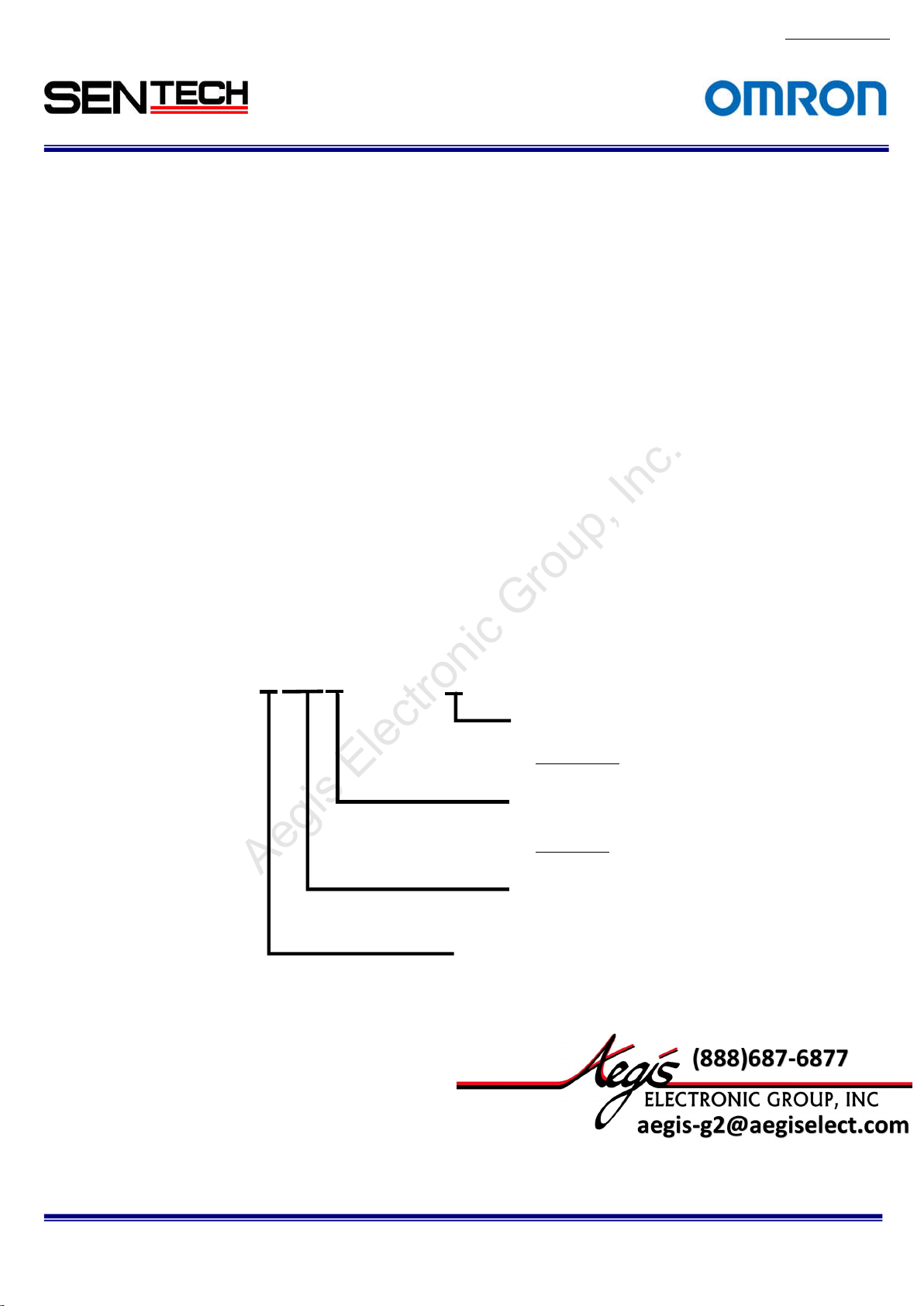
1.2. Naming
Specification
(Global Shutter)
No.13S0
80-10
STC-CMxxxxPCL-x
None: Standard
NIR: Near IR
Sensor Size
3: 1/3 inch
0: 2/3 i
nch
1:1 inch
Resolution
GA
3 : V
20: 2M Pixel
40: 4M Pixel
C: Color
B: Monochrome
STC-CMB200P
Specifications and Users guide
CL / STC-CMC200PCL / STC-CMB401PCL / STC-CMC401PCL
6
Page 7
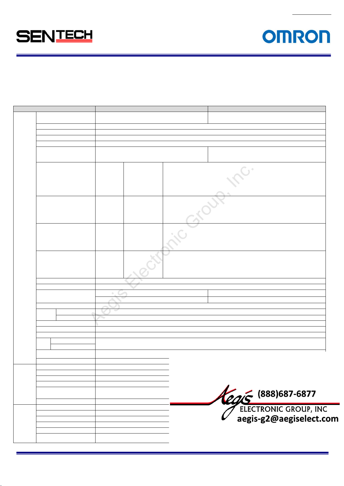
Product
STC-CMC200
PCL
STC-CMB200
PCL
Active picture ele
ments
2048 (H)
x
1088 (V)
Chip size
11.264×5.984 mm
Cell s
ize
5.5 (H) x 5.5
(V) µm
Scanning system
Progressive
Noise lev
el (8bit output)
Less than
3 Digit (Gain 0 dB)
Dynam
icrange
60 dB
Minimum sce
ne illumination
Sync. System
Internal
'@10bit ou
tput
MIDEUM /
BASE configuration
Shutter s
peed
45 se
conds to
21u se
conds (Variable at line)
, from 22 u second
s (Variable at
usec)
Digital gain
1x to 5x
Gamma
1.0
Consum
ption
Communica
tion
RS232 via Ca
mera Link connector
Dimensions
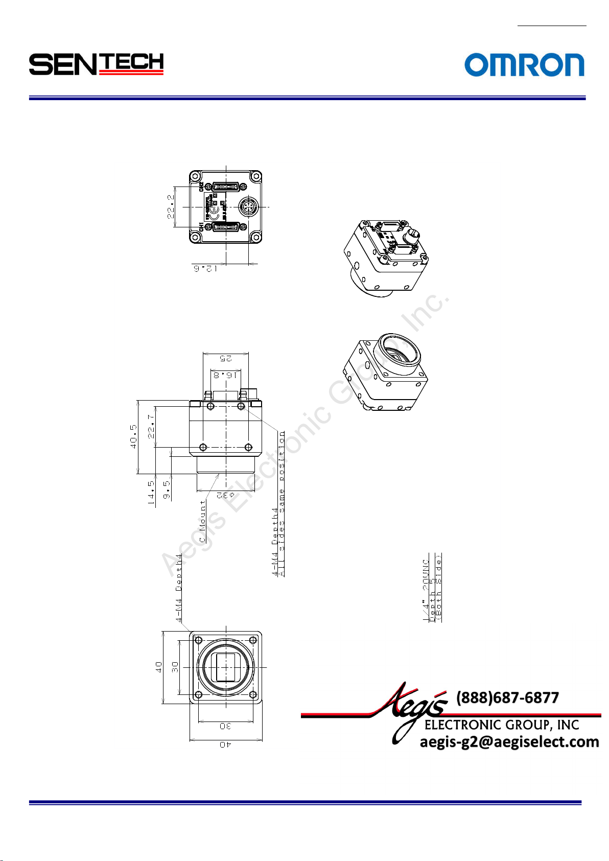
40 (W) x 40 (H) x 40.5 (D) mm (Excluding the connector)
Optical filter
No IR
cut filter
Material
Aluminu
m (AC)
Lens mount
C mount
Weight
Approxim
ately
90 g
Operati
onal temperature
-5 to 40 deg
. C
Storage temperature
-30 to 65 deg. C
Vibration
20Hz t
o 200Hz to 20Hz (5min./cycle), acceleration 10G, XYZ 3
directi
ons 30 min. each)
Shock
Acceleration
38G, half amplitude 6ms, XYZ 3 directions 3times each
Standa
rd compliancy
EMS: EN61000-6-2, EMI
: EN550
11 (Class A)
For more information please contact Aegis Electronic Group, Inc. *(888)687-6877 *aegis-g2@aegiselect.com *http://www.aegiselect.com
Aegis Electronic Group, Inc.
2. Specifications
2.1. Electronic spe
2.1.1. STC-
CMB200PCL
Color)
cifications / Mechanical specifications / Environmental specifications
(2Meg, Monoc
hrome) / STC-
CMB200PCL
-NIR (2Meg, Ne
ar IR) / STC-
No.13S0
CMC200PCL
80-10
(2Meg,
Electro
nic
spec
ations
Imager 2/3" Meg color progressive CMOS
ific
Scanning
Pixel frequ
sensor
Frame rate
Vertical frequency of
the Camera Link output
Horizon
the Camera Link output
Pixel fre
the Camera Link output
method Full scanning, Variable ROI Full scanning, Variable ROI
ency of the
tal frequency of
quency o
1X2-1Y
1X4-1Y
1X8-1Y
1X10⁻¹Y
1X2-1Y
1X4-1Y
1X8-1Y
1X10⁻¹Y
1X2
-1Y
1X4-1Y
1X8-1Y
1X10⁻¹Y
1X2-1Y
1X4-1Y
1X8-1Y
1X10⁻¹Y
(CMOSIS: CMV2000)
(8bit/10bit):
(8bit/10bit):
(8bit):
(8bit):
(8bit/10bit):
(8bit/10bit):
(8bit):
(8bit):
(8bit/10bit):
(8bit/10bit):
(8bit):
(8bit):
(8bit/10bit):
(8bit/10bit):
(8bit):
(8bit):
2/3" Meg monochrome progressive CMOS
Binning scanning,
10.625MHz (2,048 x 1,088), 21.250MHz (1,024 x 1,088),
42.500MHz ( 512 x 1,088)
21.250MHz (2,048 x 1,088), 42.500MHz (1,024 x 1,088)
42.500MHz (2,048 x 1,088)
48.000MHz (2,040 x 1,088)
73.8fps (2,048 x 1,088),147.6fps (1,024 x 1,088),295.1fps (512 x 1,088)
147.6fps (2,048 x 1,088), 295.1fps (1,024 x 1,088)
295.1fps (2,048 x 1,088)
333.3fps (2,040 x 1,088)
82kHz (2,048 x 1,088), 164kHz (1,024 x 1,088), 329kHz (512 x 1,088)
164kHz (2,048 x 1,088), 329kHz (1,024 x 1,088)
329kHz (2,048 x 1,088)
372kHz (2,040 x 1,088)
85MHz/42.5MHz
85MHz/42.5MHz
85MHz/42.5MHz
85MHz/42.5MHz
(CMOSIS: CMV2000)
Binning variable
ROI *1
F1.2 1 Lux at F1.2
- TBD Lux at F1
TAP / FULL / MIDEUM / BASE configuration
± 10% (PoCL or Power/IO connector)
Less than 3.0 W
Power/IO connector: HR10A-7R-6PB (Hirose) or equivalent
.2
Mechan
ical
specific
ations
Environ
men
tal
specific
ations
*Near
IR model (-NIR)
Video
ou
Po
wer
Operation mode Free-run, Edge preset trigger (V-reset), Pulse width trigger (V-reset)
Interface connector Camera Link connector: SDR connector x 2
RoHS RoHS compliance
'@8bit output 10
tput
Input voltage 12Vdc
2 Lux at
*1: Binning support on 8,10bit
STC-CMB200P
Specifications and Users guide
CL / STC-CMC200PCL / STC-CMB401PCL / STC-CMC401PCL
7
Page 8

Product
STC- CMC401PCL
STC- CMB401PCL
Active picture elements
2048 (H)
x 2048 (V)
Chip size
11.264×1
1.264 mm
Cell size
5.5 (H) x 5.5 (V) µm
Scanning
system
Progres
sive
Noise lev
el (8bit output)
Less than
3 Digit (Gain 0 dB)
Dynamicrange
60 dB
Sync. Sy
stem
Internal
output
'@10bit ou
tput
MIDEUM /
BASE configuration
Shutter s
peed
45 se
conds to 25.8u seconds (Variable at line)
Digital gain
1x to 4x
Gamma
1.0
Less than 3.2 W
Consumption
Communica
tion
RS232 via Ca
mera Link
conne
ctor
Dimen
sions
40 (W) x 40 (H) x 40.5 (D) mm
(Excluding the connector
)
Optical filter
No IR cut filter
Material
Aluminu
m (AC)
Lens mount
C mount
Weight
Approxim
ately
90 g
Operational temperature
-5 to 40 deg. C
Storag
e temperature
-30 to 65 de
g. C
Vibration
20Hz t
o 200Hz to 20Hz (5min./cycle),
acceler
ation 10G, XYZ 3 directions 30 min. each)
Shock
Acceleration 38G, half amplitude 6ms, XYZ 3 directions 3times each
Standa
rd compliancy
EMS: EN61000-6-2, EMI
: EN550
11 (Class A)
For more information please contact Aegis Electronic Group, Inc. *(888)687-6877 *aegis-g2@aegiselect.com *http://www.aegiselect.com
Aegis Electronic Group, Inc.
2.1.2
No.13S0
80-10
STC-CMB401PCL (4Meg, Monochrome) / STC-CMB401PCL-NIR (4Meg,Near IR) /STC-CMC401PCL (4Meg,
Color)
Electron
ic
ific
spec
ations
Imager 1" 4Meg color progressive CMOS
(CMOSIS: CMV4000)
Scanning
Pixel frequ
sensor
Frame rate
Vertical frequency of
the Camera Link output
Horizon
the Camera Link output
Pixel frequency o
the Camera Link output
method Full scanning, Variable ROI Full scanning, Variable ROI
ency of the
tal frequency of
1X2-1Y
1X4-1Y
1X8-1Y
1X10⁻¹Y
1X2-1Y
1X4-1Y
1X8-1Y
1X10⁻¹Y
1X2
-1Y
1X4-1Y
1X8-1Y
1X10⁻¹Y
1X2-1Y
1X4-1Y
1X8-1Y
1X10⁻¹Y
(8bit/10bit):
(8bit/10bit):
(8bit):
(8bit):
(8bit/10bit):
(8bit/10bit):
(8bit):
(8bit):
(8bit/10bit):
(8bit/10bit):
(8bit):
(8bit):
(8bit/10bit):
(8bit/10bit):
(8bit):
(8bit):
10.625MHz (2,048 x 2,048), 21.250MHz (1,024 x 2,048),
42.500MHz ( 512 x 2,048)
21.250MHz (2,048 x 2,048), 42.500MHz (1,024 x 2,048)
42.500MHz (2,048 x 2,048)
48.000MHz (2,040 x 2,048)
39.7fps (2,048 x 2,048), 79.2fps (1,024 x 2,048), 158.6fps (512 x 2,048)
79.3fps (2,048 x 2,048), 158.6fps (1,024 x 2,048)
158.6fps (2,048 x 2,048)
179.2fps (2,040 x 2,048)
82kHz (2,048 x 2,048), 164kHz (2,024 x 1,048), 329kHz (512 x 2,048)
164kHz (2,048 x 2,048), 329kHz (1,024 x 2,048)
329kHz (2,048 x 2,048)
372kHz (2,040 x 2,048)
85MHz/42.5MHz
85MHz/42.5MHz
85MHz/42.5MHz
85MHz/42.5MHz
1" 4Meg monochrome progressive CMOS
(CMOSI
Binning scanning, Binning variable ROI*1
S: CMV4000)
m scene
Minimu
illumination *Near
Video
Power Input voltage 12Vdc
Operati
Mechan
ical
specific
ations
Environ
mental
specific
ations
Interface connector Camera Link connector: SDR connector x 2
RoHS Ro
STC-CMB200P
'@8bit output 10
on mode Free-run, Edge preset trigger (V-reset), Pulse width trigger (V-reset)
CL / STC-CMC200PCL / STC-CMB401PCL / STC-CMC401PCL
Specifications and Users guide
Less than 1 Lux at F1.2 Less than 1 Lux at F1.2
- TBD Lux at F1
TAP / FULL / MIDEUM / BASE configuration
± 10% (PoCL or Power/IO connector)
HS compliance
.2
8
Page 9

*1: Binning
For more information please contact Aegis Electronic Group, Inc. *(888)687-6877 *aegis-g2@aegiselect.com *http://www.aegiselect.com
Aegis Electronic Group, Inc.
support on 8,10bit
No.13S0
80-10
STC-CMB200P
Specifications and Users guide
CL / STC-CMC200PCL / STC-CMB401PCL / STC-CMC401PCL
9
Page 10
10
For more information please contact Aegis Electronic Group, Inc. *(888)687-6877 *aegis-g2@aegiselect.com *http://www.aegiselect.com
Aegis Electronic Group, Inc.
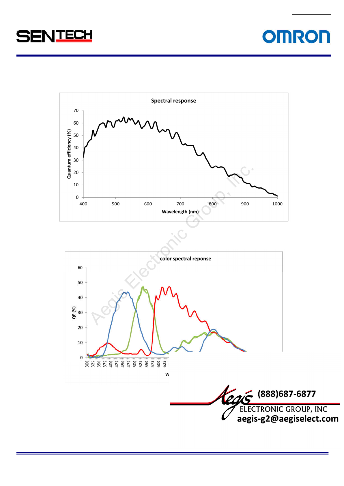
2.2 Spectral
2.2.1 STC-CMB200PCL / STC-CMB401PCL
Sensitivity Characteristics
No.13S0
80-10
2.2.2
STC-CMC200PCL / STC-CMC401PCL
STC-CMB200P
Specifications and Users guide
CL / STC-CMC200PCL / STC-CMB401PCL / STC-CMC401PCL
Page 11
11
For more information please contact Aegis Electronic Group, Inc. *(888)687-6877 *aegis-g2@aegiselect.com *http://www.aegiselect.com
Aegis Electronic Group, Inc.
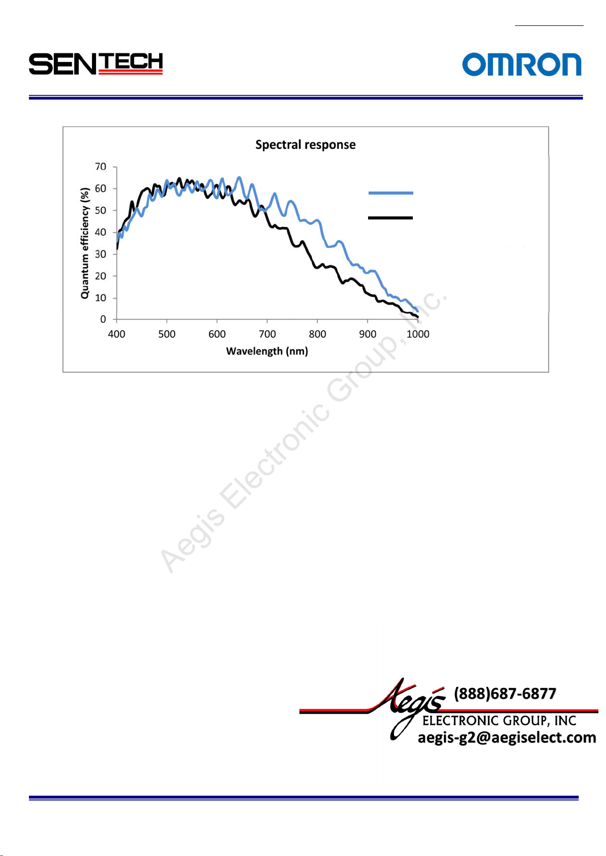
2.2.3
STC-CMB200PCL NIR / STC-CMB401PCL-NIR (Near IR model)
Near IR Model
Normal Model(Mono)
No.13S0
80-10
STC-CMB200P
Specifications and Users guide
CL / STC-CMC200PCL / STC-CMB401PCL / STC-CMC401PCL
Page 12
No.13S0
12
For more information please contact Aegis Electronic Group, Inc. *(888)687-6877 *aegis-g2@aegiselect.com *http://www.aegiselect.com
Aegis Electronic Group, Inc.
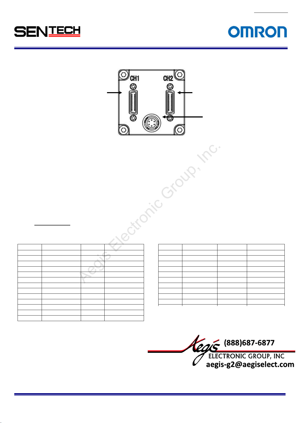
2.3 Connector
specifications
26-pin SDR c
(Base
Camera Link Connector)
onnector
26-pin SDR connector
(Medium / Full
Camera Link Connector)
Power/IO c
onnector
2.3.1 Camera Link connectors:
SDR (3M) equiva
lent x 2
(CAUT
ION)
This product is PoCL type.
When the frame grabber board and the cable are applicable for the PoCL, the frame grabber
board supplies the power to the camera. In this case, please DO NOT supply the power from
the Power/IO connector.
When the frame grabber board and the cable are NOT applicable for the PoCL, please input the
power from the Power/IO connector.
Pin assignment
Base Camer
a Link Connector Medium / Full Camera Link Connector
Pin No. Signal Name Pin No. Signal Name Pin No. Signal Name Pin No. Signal Name
1 +12V 14 GND 1 +12V 14 GND
2 X0- 15 X0+ 2 Y0- 15 Y0+
3 X1- 16 X1+ 3 Y1- 16 Y1+
4 X2- 17 X2+ 4 Y2- 17 Y2+
5 Xclk- 18 Xclk+ 5 Yclk- 18 Yclk+
6 X3- 19 X3+ 6 Y3- 19 Y3+
7 SerTC+ 20 SerTC- 7 100Ω 20 100Ω
8 SerTFG- 21 SerTFG+ 8 Z0- 21 Z0+
9 CC1- (TRG) 22 CC1+ (TRG) 9 Z1- 22 Z1+
10 CC2+ 23 CC2- 10 Z2- 23 Z2+
11 CC3- 24 CC3+ 11 Zclk- 24 Zclk+
12 CC4+ 25 CC4- 12 Z3- 25 Z3+
13 GND 26 +12V 13 GND 26 +12V
80-10
STC-CMB200P
CL / STC-CMC200PCL / STC-CMB401PCL / STC-CMC401PCL
Specifications and Users guide
Page 13
13
For more information please contact Aegis Electronic Group, Inc. *(888)687-6877 *aegis-g2@aegiselect.com *http://www.aegiselect.com
Aegis Electronic Group, Inc.
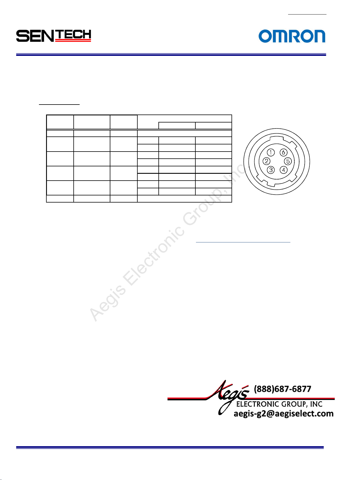
2.3.2
No.13S0
Power/IO connector: HR10A-7R-6PB (Hirose) or equivalent.
This connector is for 12Vdc power input and the input and output signals.
The trigger input and sync input /output signals can be assigned through the
camera setting communication.
Pin assignment
Pin No Signal Name IN/OUT Voltage
LowVolta
1 GND IN
2 SP-4 IN/OUT IN 0 ~ +0.99V +2.3 ~ +5.0V
OUT 0V +3.3V
3 SP-3 IN/OUT IN 0 ~ +0.99V +2.3 ~ +5.0V
OUT 0V +3.3V
4 SP-2 IN/OUT IN 0 ~ +0.99V +2.3 ~ +5.0V
OUT 0V +3.3V
5 SP-1 IN/OUT IN 0 ~ +0.99V +2.3 ~ +5.0V
OUT 0V +3.3V
6 +12Vdc IN
(Note 1)
rigger input signal can be assigned either on Camera Link connector (CC1) or on the No. 2 pin of the
T
power/IO connector through the camera setting communication.
As for the actual setting of hardware trigger, please refer to
ge
0V
+12Vdc
HighVoltage
0.エラー! 参照
元が見つかりません。
80-10
STC-CMB200P
Specifications and Users guide
CL / STC-CMC200PCL / STC-CMB401PCL / STC-CMC401PCL
Page 14
14
For more information please contact Aegis Electronic Group, Inc. *(888)687-6877 *aegis-g2@aegiselect.com *http://www.aegiselect.com
Aegis Electronic Group, Inc.
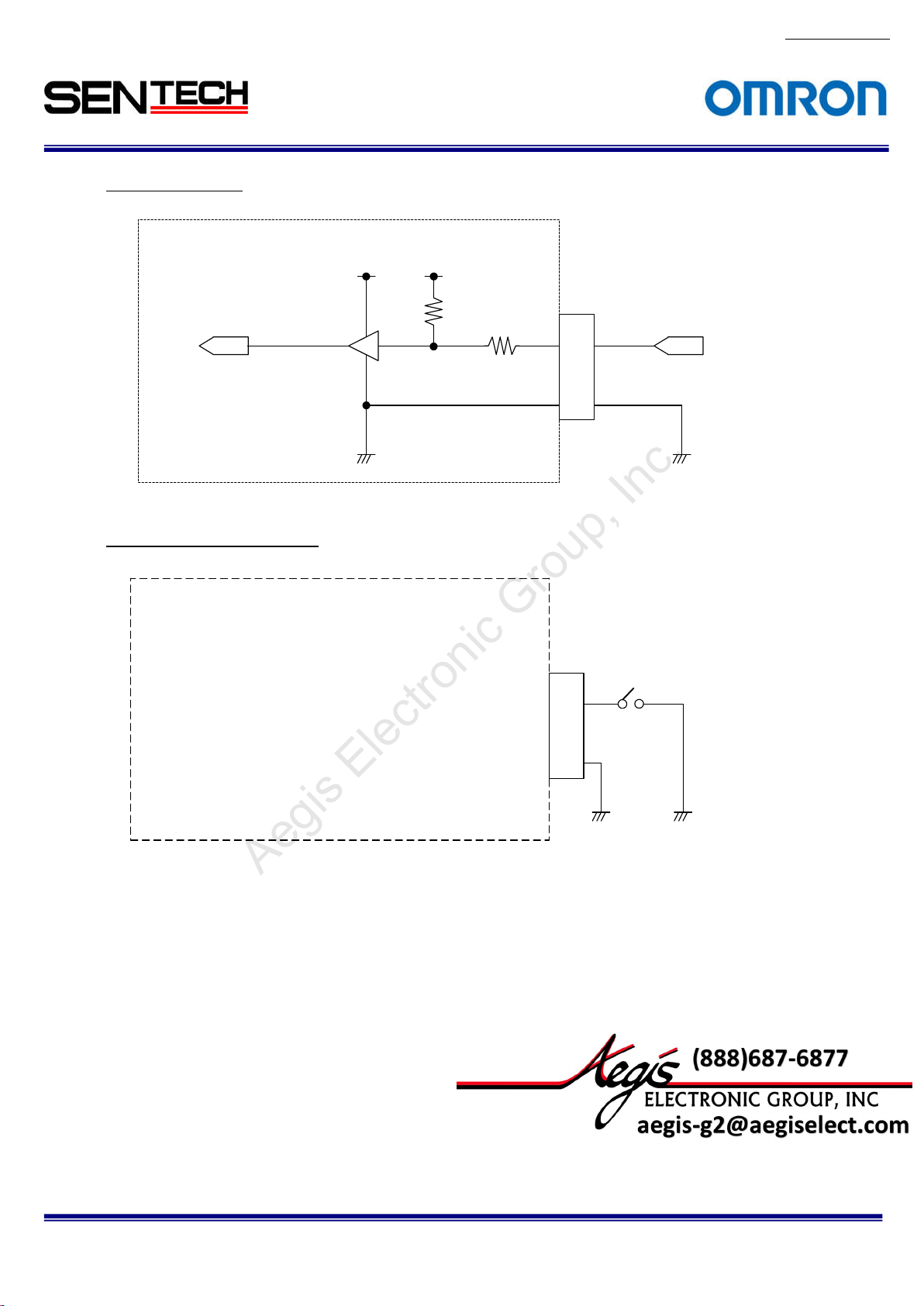
Input Signa
l Circuit
Cam
era
Camera
ut
inp
(to FPGA)
Input Signal Circuit Examples
Came
ra
input
(to FPGA)
TC7WH24
TC7WH241FK
+3.3V
Camera
1FK
+3.3V
+3.3V
+3.3V
47kΩ
47kΩ
100Ω
100Ω
6Pin Conecto
2,3,4,
5
1
6Pin Conector
Pin. 2 or 3 o
2,3,4,
5
1
r
2 or 3 or 4 or 5
Pin.
r 4 or 5
User INPUT
GND
No.13S0
80-10
STC-CMB200P
CL / STC-CMC200PCL / STC-CMB401PCL / STC-CMC401PCL
Specifications and Users guide
Page 15
15
For more information please contact Aegis Electronic Group, Inc. *(888)687-6877 *aegis-g2@aegiselect.com *http://www.aegiselect.com
Aegis Electronic Group, Inc.
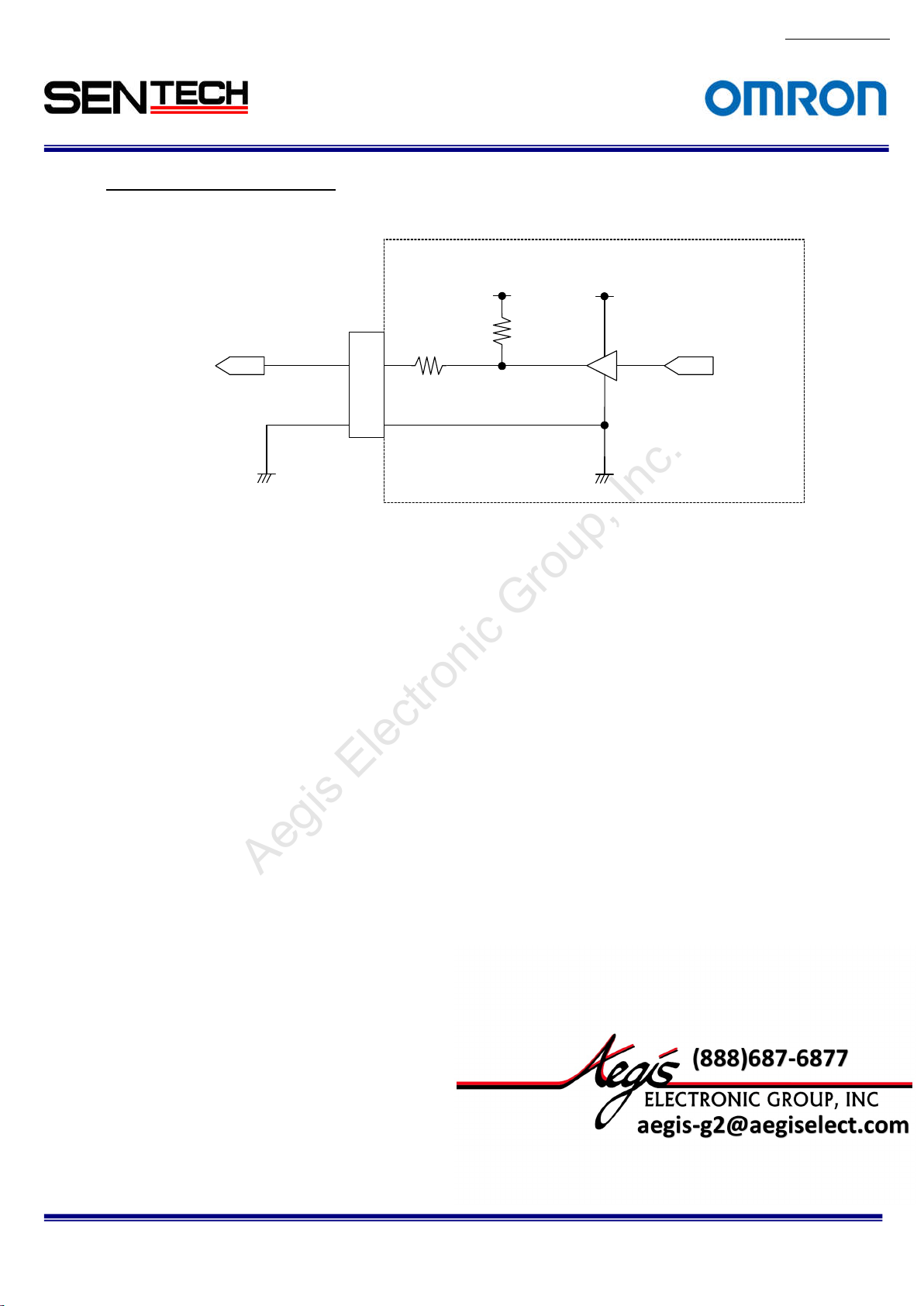
Output Signa
User Output
Voltage 0 to
+3.3V DC
l Circuit/ Examples
Pin. 2 or 3 or
GND
6 Pin Conector
4 or 5
2,3,4,
5
1
Came
100Ω
ra
+3.3V
47kΩ
+3.3V
TC7WH241FK
Camera
o
utput
(from FPGA)
No.13S0
80-10
STC-CMB200P
Specifications and Users guide
CL / STC-CMC200PCL / STC-CMB401PCL / STC-CMC401PCL
Page 16
16
For more information please contact Aegis Electronic Group, Inc. *(888)687-6877 *aegis-g2@aegiselect.com *http://www.aegiselect.com
Aegis Electronic Group, Inc.
3. Dimensions
3.1. STC-CMB200P
CL / STC-CMB200PCL-NIR / STC-CMC200PCL
No.13S0
80-10
Unit: m
STC-CMB200P
Specifications and Users guide
CL / STC-CMC200PCL / STC-CMB401PCL / STC-CMC401PCL
m
Page 17

17
For more information please contact Aegis Electronic Group, Inc. *(888)687-6877 *aegis-g2@aegiselect.com *http://www.aegiselect.com
Aegis Electronic Group, Inc.
3.2 STC-CMB401PCL /
STC-CMB401PCL-NIR / STC-CMC401PCL
No.13S0
80-10
Unit: m
STC-CMB200P
Specifications and Users guide
CL / STC-CMC200PCL / STC-CMB401PCL / STC-CMC401PCL
m
Page 18

18
For more information please contact Aegis Electronic Group, Inc. *(888)687-6877 *aegis-g2@aegiselect.com *http://www.aegiselect.com
Aegis Electronic Group, Inc.
4. Camera Installation
For the i
Control software or Serial communication software to access the camera register.
As for using the software, please refer to the 0.
Control So
specifications.
Camera Link
When using on Full Configuration, please use the cable that has qualification.
Frame Graber should support Full, Medium, Base Configuration. When using the PoCL, Frame Graber
should support PoCL.
nstallation of this camera, these equipment as bellow are required.
ftware. As for accessing the register, please refer to the 7.The communication protocol
Cable x 2 (SDR Connector : Camera side)
No.13S0
80-10
STC-CMB200P
Specifications and Users guide
CL / STC-CMC200PCL / STC-CMB401PCL / STC-CMC401PCL
Page 19
19
For more information please contact Aegis Electronic Group, Inc. *(888)687-6877 *aegis-g2@aegiselect.com *http://www.aegiselect.com
Aegis Electronic Group, Inc.
5. The camera output timing charts
5.1. The horizontal t
As for the vertical timing, please refer to 5.2.エラー! ブックマークが自己参照を行っています。. Highs Speed
Clock and Lo
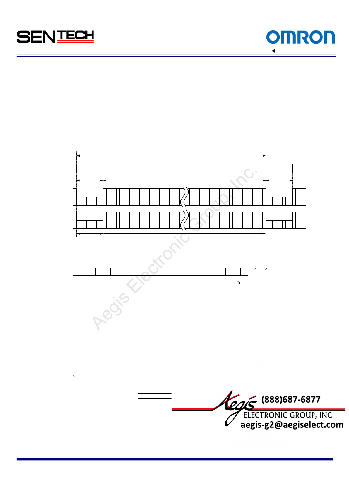
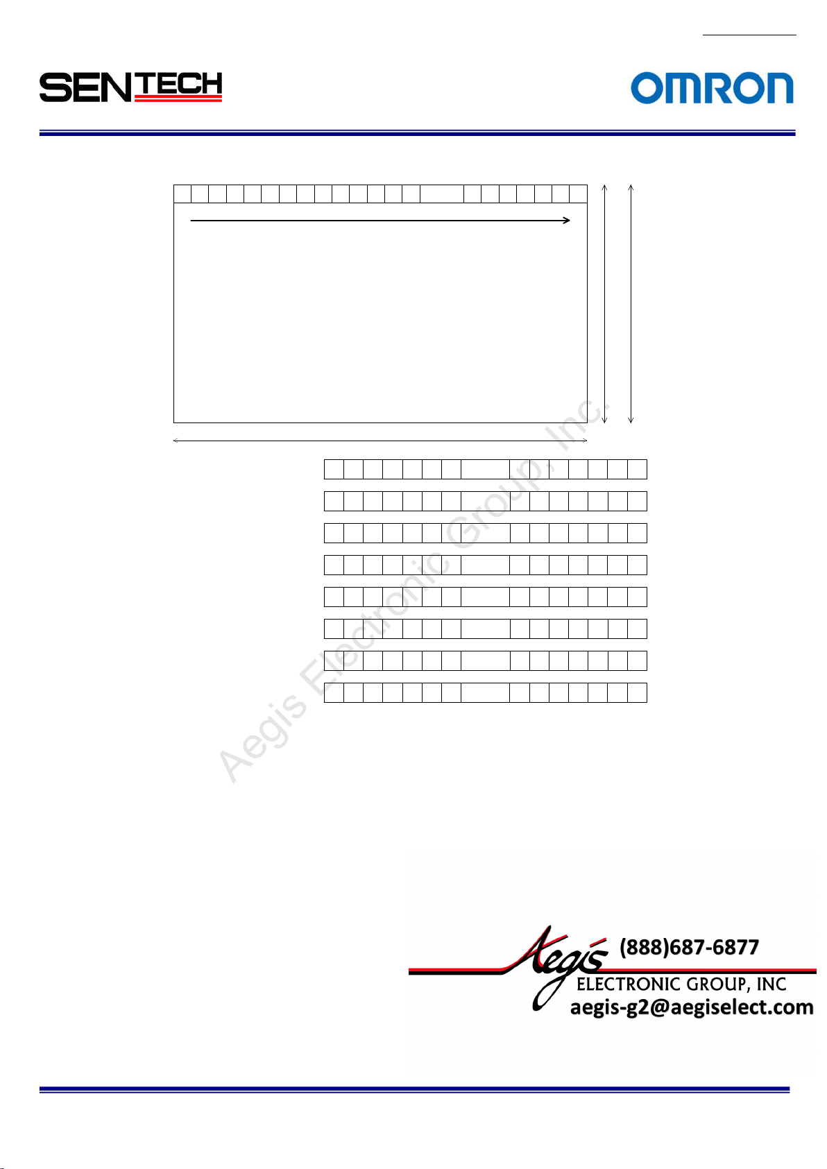
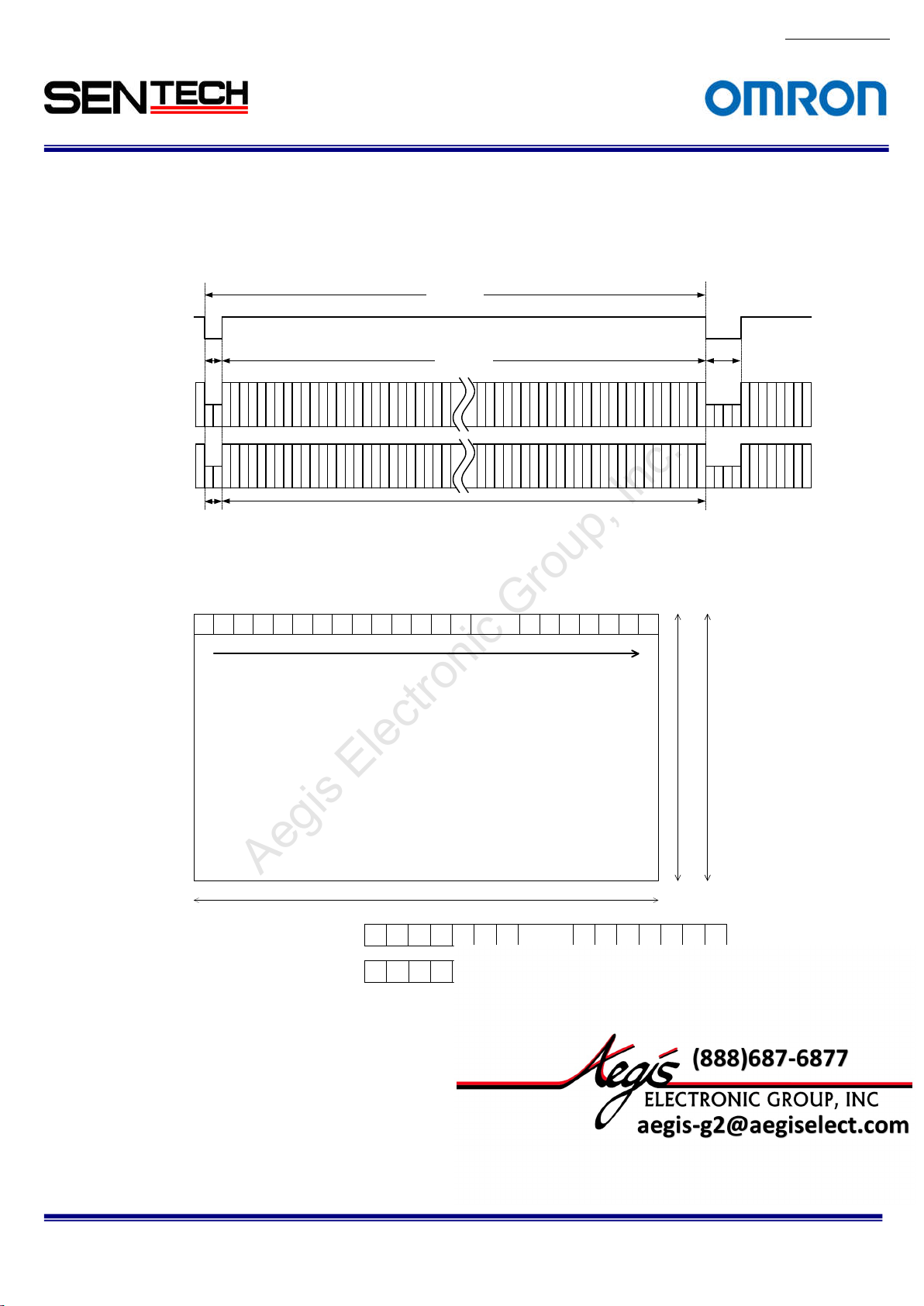
51.1 2 Taps (
1X2-1Y) / Horizontal 2,048 pixels
LVAL
Video out
ap 1: DA)
(T
Video out
ap 2: DB)
(T
The pixel order for the Image
TAP1: DA output pixels
TAP2: DB output pixels
imings (STC-CMB/CMC200PCL, CMB/CMC401PCL)
w Speed Clock are existed as Pixel Clock.
8 CLK
135
246
Horizontal
blanking
1 2
3 4 ...... 20425 6 7 8 9 10 11 12 13 14 20 43 2044 2045 2046 2047 2048
1 CLK =
11.764 nseconds(85MHz)
1 CLK = 23.524 nseconds(42.5MHz)
1,032
CLK
CLK
1,024
Video o
els
2,048 pix
1 3 5 7 ...... 20359 11 13 2037 2039 2041 20 43 2045 2047
2 4 6 8 ...... 20 3610 12 14 2038 2040 2042 2044 2046 2048
utput
One horizontal (1H)
2043
2044
2,048 lines
(STC-CMB4MCL/CMC4MCL)
47
20
2045
2046
2048
8 CLK
1,088 lines
(STC-CMB2MCL/CMC2MCL)
No.13S0
LED
80-10
STC-CMB200P
CL / STC-CMC200PCL / STC-CMB401PCL / STC-CMC401PCL
Specifications and Users guide
Page 20
20
For more information please contact Aegis Electronic Group, Inc. *(888)687-6877 *aegis-g2@aegiselect.com *http://www.aegiselect.com
Aegis Electronic Group, Inc.
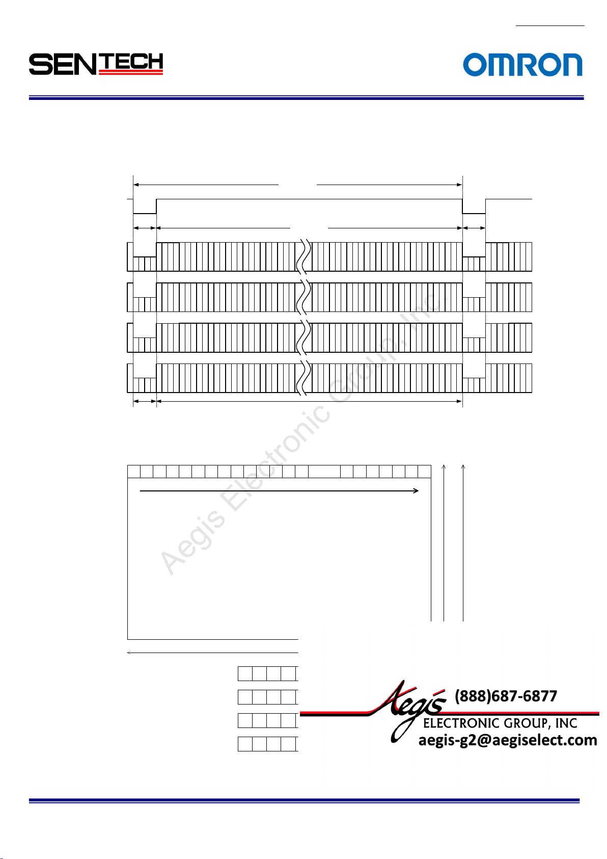
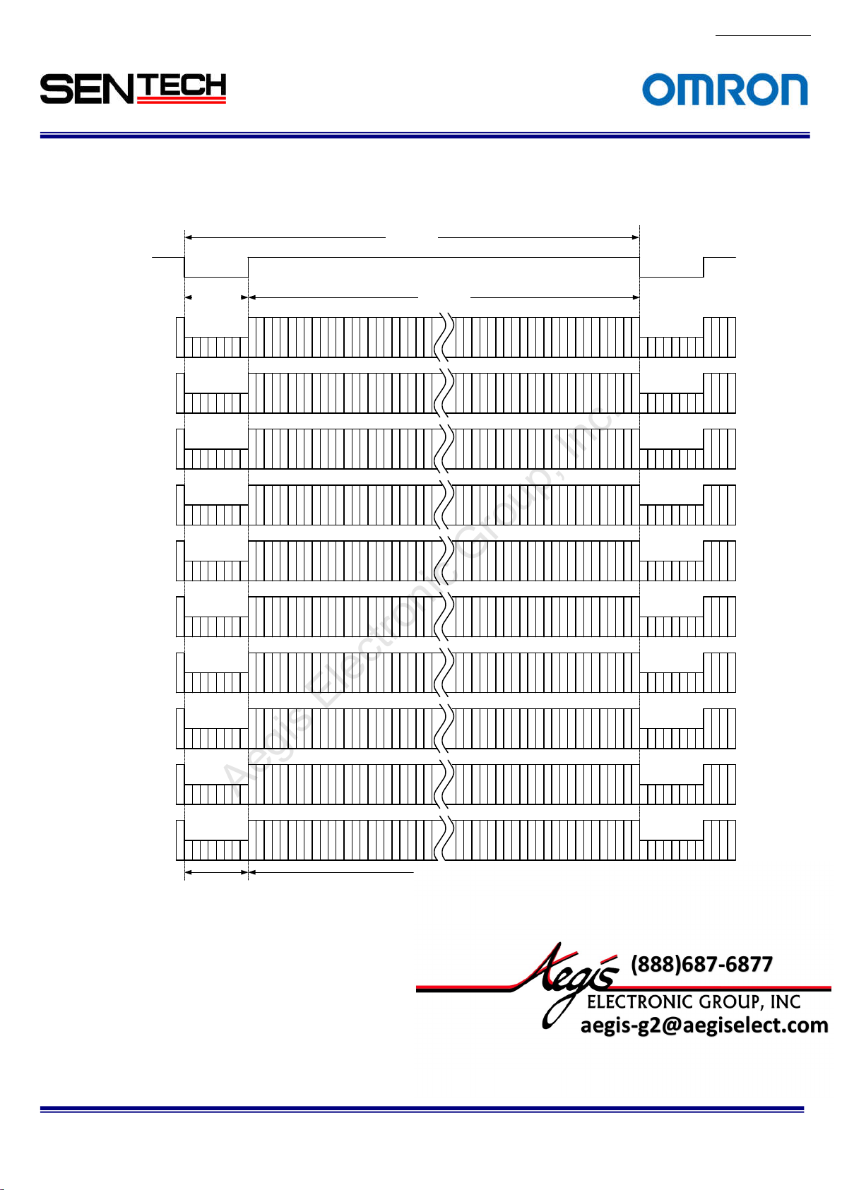
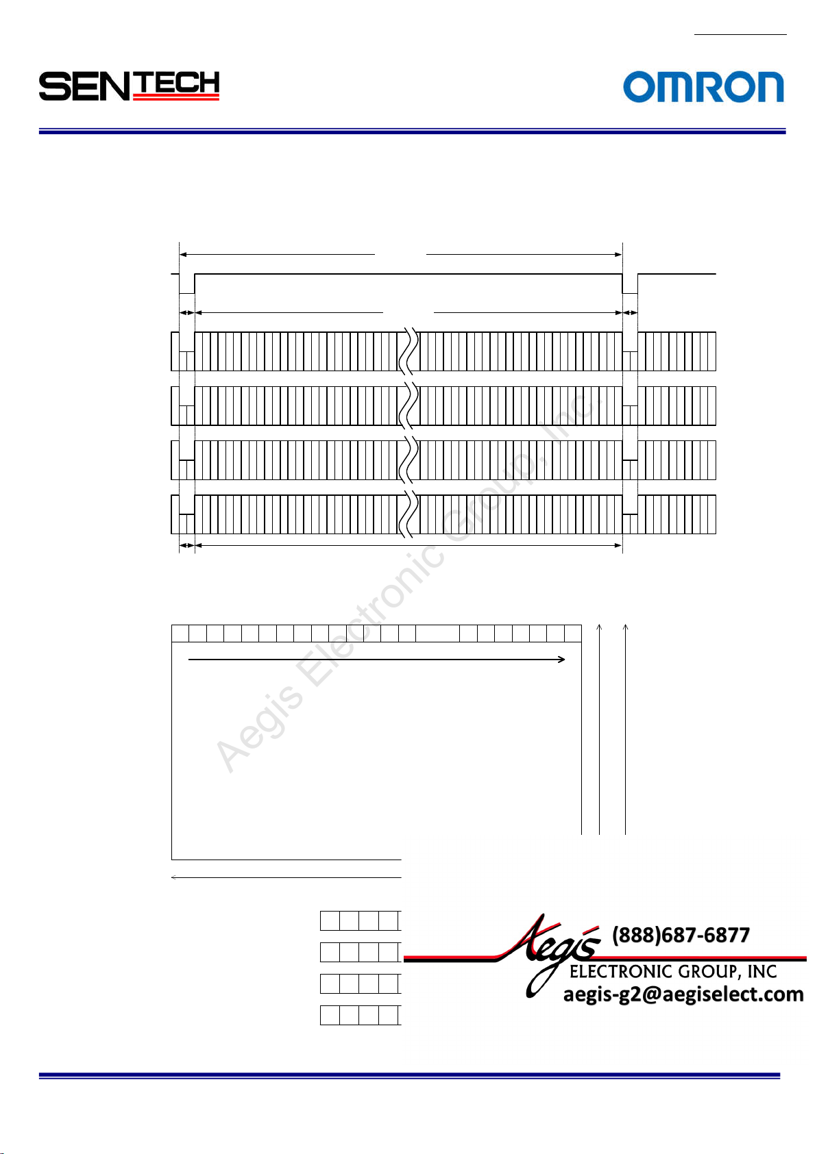
5.1.2
4Taps (1X4-1Y) / Horizontal 2,048 pixels
LVAL
4 CLK
Video out
ap1: DA)
(T
159
Video out
(Tap2: DB)
2
6
Video out
(Tap3: DC)
3
7
Video out
(Tap4: DD)
4
8
Horizontal
bl
anking
The pixel order for the Image
1 2
3 4 ...... 20425 6 7 8 9 10 11 12 13 14 20 43 2044 2045 2046 2047 2048
TAP1: DA output pixels
TAP2: DB output pixels
TAP3: DC output pixels
TAP4: DD output pixels
No.13S0
80-10
1 CLK = 11.764 nseconds(85MHz)
1 CLK = 23.524 nseconds(42.5MHz)
516 CLK
One
horizontal (1H)
512 CLK
4 CLK
2037
2041
2045
10
11
12
Video o
2,048 pix
1 5 9 13 ...... 20 2117 21 25 2025 2029 2033 2037 2041 2045
2 6 10 14 ...... 202218 22 26 2026 2030 2034 2038 2042 2046
3 7 11 15 ......202319 23 27 2027 2031 2035 2039 2043 2047
4 8 12 16 ......202420 24 28 2028 2032 2036 2040 2044 2048
utput
els
46
2038
2042
20
2039
2043
2047
2040
2044
2048
2,048 line
1,088 line
s (STC-CMB4MCL/CMC4MCL)
s (STC-CMB2MCL/CMC2MCL)
STC-CMB200P
CL / STC-CMC200PCL / STC-CMB401PCL / STC-CMC401PCL
Specifications and Users guide
Page 21
21
For more information please contact Aegis Electronic Group, Inc. *(888)687-6877 *aegis-g2@aegiselect.com *http://www.aegiselect.com
Aegis Electronic Group, Inc.
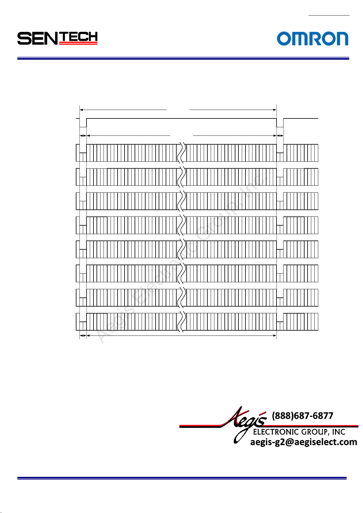
5.1.3
8 Taps (1X8-1Y) / Horizontal 2,048 pixels
LVA
L
2 CLK 2 CLK
Video out
(Tap1:DA)
1
9
17
Video out
(Tap2:DB)
2
10
18
258 CLK
256 CLK
No.13S0
1 CLK = 11.764 nseconds(85MHz)
1 CLK = 23.524 nseconds(42.5MHz)
One
horizontal (1H)
2025
2033
2041
2026
2034
2042
80-10
Video out
(Tap3:DC)
Vi
deo out
(Tap4:DD)
Video out
(Tap5:DE)
Video out
(Tap6:DF)
Video out
(Tap7:DG)
Video out
(Tap8:DH)
3
4
5
6
7
8
Horizontal
blanking
11
19
12
20
13
21
14
22
15
23
16
24
Video o
utput
2027
2035
2043
2028
2036
2044
2029
2037
2045
2030
2038
2046
47
2031
2039
20
2032
2040
2048
STC-CMB200P
CL / STC-CMC200PCL / STC-CMB401PCL / STC-CMC401PCL
Specifications and Users guide
Page 22
22
For more information please contact Aegis Electronic Group, Inc. *(888)687-6877 *aegis-g2@aegiselect.com *http://www.aegiselect.com
Aegis Electronic Group, Inc.
The pixel or
der for the Image
1 2
3 4 ...... 20425 6 7 8 9 10 11 12 13 14 2043 2044 2045 2046 20 47 2048
TAP1: DA output pixels
TAP2: DB output pixels
TAP3: DC output pixels
TAP4: DD output pixels
TAP5: DE output pixels
TAP6: DF output pixels
TAP7: DG output pixels
TAP8: DH output pixels
2,048 line
s (STC-CMB4MCL/CMC4MCL)
2,048 pix
els
1 9 17 25 ......199333 41 49 2001 2009 2017 2025 2033 2041
2 10 18 26 ...... 199434 42 50 2002 2010 2018 2026 2034 2042
3 11 19 27 ......199535 43 51 2003 2011 2019 2027 2035 2043
4 12 20 28 ......199636 44 52 2004 2012 2020 2028 2036 2044
5 13 21 29 ......199737 45 53 2005 2013 2021 2029 2037 2045
6 14 22 30 ...... 199838 46 54 2006 2014 2022 2030 2038 2046
7 15 23 31 ......199939 47 55 2007 2015 2023 2031 2039 2047
8 16 24 32 ......200040 48 56 2008 2016 2024 2032 2040 2048
No.13S0
80-10
1,088 line
s (STC-CMB2MCL/CMC2MCL)
STC-CMB200P
CL / STC-CMC200PCL / STC-CMB401PCL / STC-CMC401PCL
Specifications and Users guide
Page 23
23
For more information please contact Aegis Electronic Group, Inc. *(888)687-6877 *aegis-g2@aegiselect.com *http://www.aegiselect.com
Aegis Electronic Group, Inc.
5.1.4
10 Taps (1X10⁻¹Y) / Horizontal 2,040 pixels
LVAL
Video out
(T
ap1:DA)
24 to 2
CLK
5
Video out
(T
ap2:DB)
No.13S0
80-10
1 CLK = 12.500 nseconds (80MHz)
1 CLK = 25.000 nseconds(40MHz)
215 CLK
One horizontal (1H)
204 CLK
5
15
25
6
16
26
2015
2025
2035
36
2016
2026
20
Video out
(Tap3:DC)
Video out
(Tap4:DD)
Video out
(Tap5:DE)
Video out
(Tap6:DF)
Video out
(Tap7:DG)
Video out
(Tap8:DH)
Video out
(Tap9:DI)
Video out
(Tap10:DJ)
7
17
8
18
9
19
102030
112131
122232
132333
142434
27
28
29
2017
2027
2037
2018
2028
2038
2019
2029
2039
2020
2030
2040
2021
2031
2041
2022
2032
2042
2023
2033
2043
2024
2034
2044
Horizont
al
Video output
blanking
STC-CMB200P
CL / STC-CMC200PCL / STC-CMB401PCL / STC-CMC401PCL
Specifications and Users guide
Page 24
24
For more information please contact Aegis Electronic Group, Inc. *(888)687-6877 *aegis-g2@aegiselect.com *http://www.aegiselect.com
Aegis Electronic Group, Inc.
The pixel or
der for the Image
TAP1: DA output pixels
TAP2: DB output pixels
TAP3: DC output pixels
TAP4: DD output pixels
TAP5: DE output pixels
TAP6: DF output pixels
TAP7: DG output pixels
TAP8: DH output pixels
TAP9: DG output pixels
TAP10: DH output pixels
15 16
17 18 ...... 20385 6 7 8 9 10 11 12 13 14 2039 2040 2041 20 42 2043 2044
2,048 lines (STC-CMB4MCL/CMC4MCL)
1,088 line
s (STC-CMB2MCL/CMC2MCL)
2,040 pixels
5 15 25 35 ......197545 55 65 1985 1995 2005 2015 2025 2035
6 16 26 36 ...... 197646 56 66 1986 1996 2006 2016 2026 2036
7 17 27 37 ......197747 57 67 1987 1997 2007 2017 2027 2037
8 18 28 38 ......197848 58 68 1988 1998 2008 2018 2028 2038
9 19 29 39 ......197949 59 69 1989 1999 2009 2019 2029 2039
10 20 30 40 ...... 198050 60 70 1990 2000 2010 2020 20 30 2040
11 21 31 41 ......198151 61 71 1991 2001 2011 2021 2031 2041
12 22 32 42 ......198252 62 72 1992 2002 2012 2022 2032 2042
13 23 33 43 ......198353 63 73 1993 2003 2013 2023 2033 2043
14 24 34 44 ...... 198454 64 74 1994 2004 2014 2024 2034 2044
No.13S0
80-10
STC-CMB200P
CL / STC-CMC200PCL / STC-CMB401PCL / STC-CMC401PCL
Specifications and Users guide
Page 25
25
For more information please contact Aegis Electronic Group, Inc. *(888)687-6877 *aegis-g2@aegiselect.com *http://www.aegiselect.com
Aegis Electronic Group, Inc.
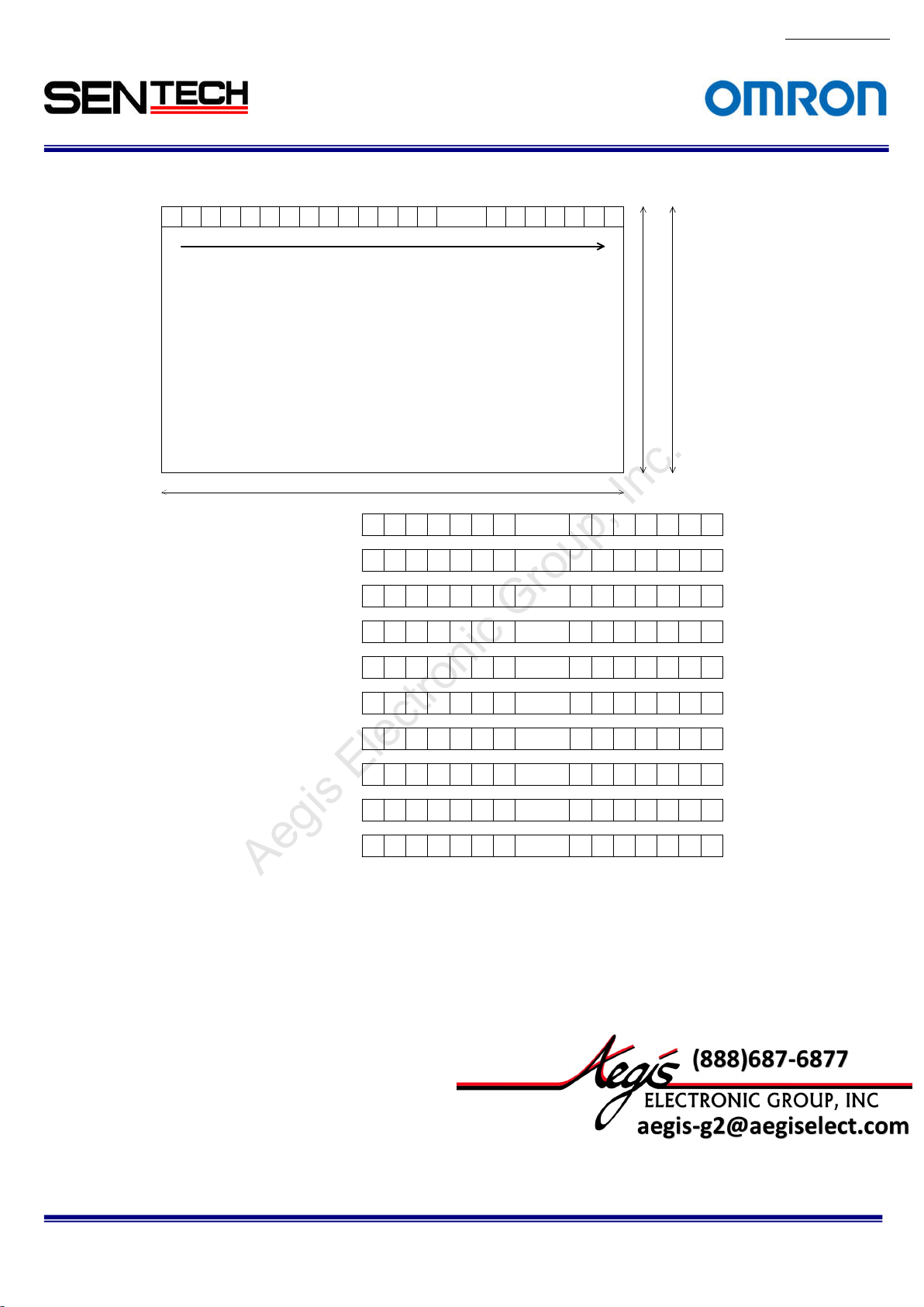
5.1.5
2Taps (1X2-1Y) / Horizontal 1,024 pixels
LVAL
4 CLK 4 CLK
Video out
ap 1: DA)
(T
135
Video out
(Tap 2: DB)
246
Horizontal
anking
bl
The pixel order for the Image
1 2
3 4 ...... 10185 6 7 8 9 10 11 12 13 14 1019 1020 1021 1022 1023 10 24
TAP1: DA output pixels
TAP2: DB output pixels
1 CLK = 11.764 nseconds(85MHz)
1 CLK = 23.524 nseconds(42.5MHz)
516 CLK
512 CLK
Video o
1,024
pixels
1 3 5 7 ...... 10119 11 13 1013 1015 1017 1019 1021 1023
2 4 6 8 ...... 101210 12 14 1014 1016 1018 1020 1022 1024
utput
horizontal (1H)
One
1023
1019
1021
1020
1022
1024
2,048 l
ines (STC-CMB4MCL/CMC4MCL)
No.13S0
80-10
1,088 l
ines (STC-CMB2MCL/CMC2MCL)
STC-CMB200P
CL / STC-CMC200PCL / STC-CMB401PCL / STC-CMC401PCL
Specifications and Users guide
Page 26
26
For more information please contact Aegis Electronic Group, Inc. *(888)687-6877 *aegis-g2@aegiselect.com *http://www.aegiselect.com
Aegis Electronic Group, Inc.
5.1.6
2Taps (1X2-1Y) / Horizontal 512 pixels
LVAL
2 CLK 2 CLK
Video out
(T
ap 1: DA)
135
Video out
(T
ap 2: DB)
246
Horizontal
bl
anking
The pixel order for the Image
1 2
3 4 ...... 5065 6 7 8 9 10 11 12 13 14 507 508 509 510 511 512
TAP1: DA output pixels
TAP2: DB output pixels
1 CLK = 11.764 nseconds(85MHz)
1 CLK = 23.524 nseconds(42.5MHz)
258 CLK
256 CLK
Video output
512 pixels
1 3 5 7 ...... 4999 11 13 501 50 3 505 507 509 511
2 4 6 8 ...... 50010 12 14 502 504 506 508 510 512
One
horizontal (1H)
1
51
507
509
508
510
512
2,048 l
ines (STC-CMB4MCL/CMC4MCL)
No.13S0
80-10
1,088 l
ines (STC-CMB2MCL/CMC2MCL)
STC-CMB200P
CL / STC-CMC200PCL / STC-CMB401PCL / STC-CMC401PCL
Specifications and Users guide
Page 27
27
For more information please contact Aegis Electronic Group, Inc. *(888)687-6877 *aegis-g2@aegiselect.com *http://www.aegiselect.com
Aegis Electronic Group, Inc.
5.1.7
4Taps / Horizontal 1,024 pixels
LVAL
2 CLK
Video out
(T
ap1: DA)
159
Video out
(Tap2: DB)
2
6
10
Video out
(Tap3: DC)
3
7
11
Video out
(Tap4: DD)
4
8
12
Horizontal
anking
bl
The pixel order for the Image
1 2
3 4 ...... 10185 6 7 8 9 10 11 12 13 14 1019 1020 1021 1022 1023 10 24
TAP1: DA output pixels
TAP2: DB output pixels
TAP3: DC output pixels
TAP4: DD output pixels
1 CLK = 11.764 nseconds(85MHz)
1 CLK = 23.524 nseconds(42.5MHz)
258 CLK
256 CLK
Video o
1,024
1 5 9 13 ...... 99717 21 25 1001 1005 1009 1013 1017 1021
2 6 10 14 ...... 99818 22 26 1002 1006 1010 1014 1018 1022
3 7 11 15 ...... 99919 23 27 1003 1007 1011 1015 1019 1023
4 8 12 16 ...... 100020 24 28 1004 1008 1012 1016 10 20 1024
utput
pixels
horizontal (1H)
One
1013
1017
1021
22
1014
1018
10
1015
1019
1023
1016
1020
1024
2,048 l
ines (STC-CMB4MCL/CMC4MCL)
No.13S0
80-10
2 CLK
1,088 l
ines (STC-CMB2MCL/CMC2MCL)
STC-CMB200P
CL / STC-CMC200PCL / STC-CMB401PCL / STC-CMC401PCL
Specifications and Users guide
Page 28

28
For more information please contact Aegis Electronic Group, Inc. *(888)687-6877 *aegis-g2@aegiselect.com *http://www.aegiselect.com
Aegis Electronic Group, Inc.
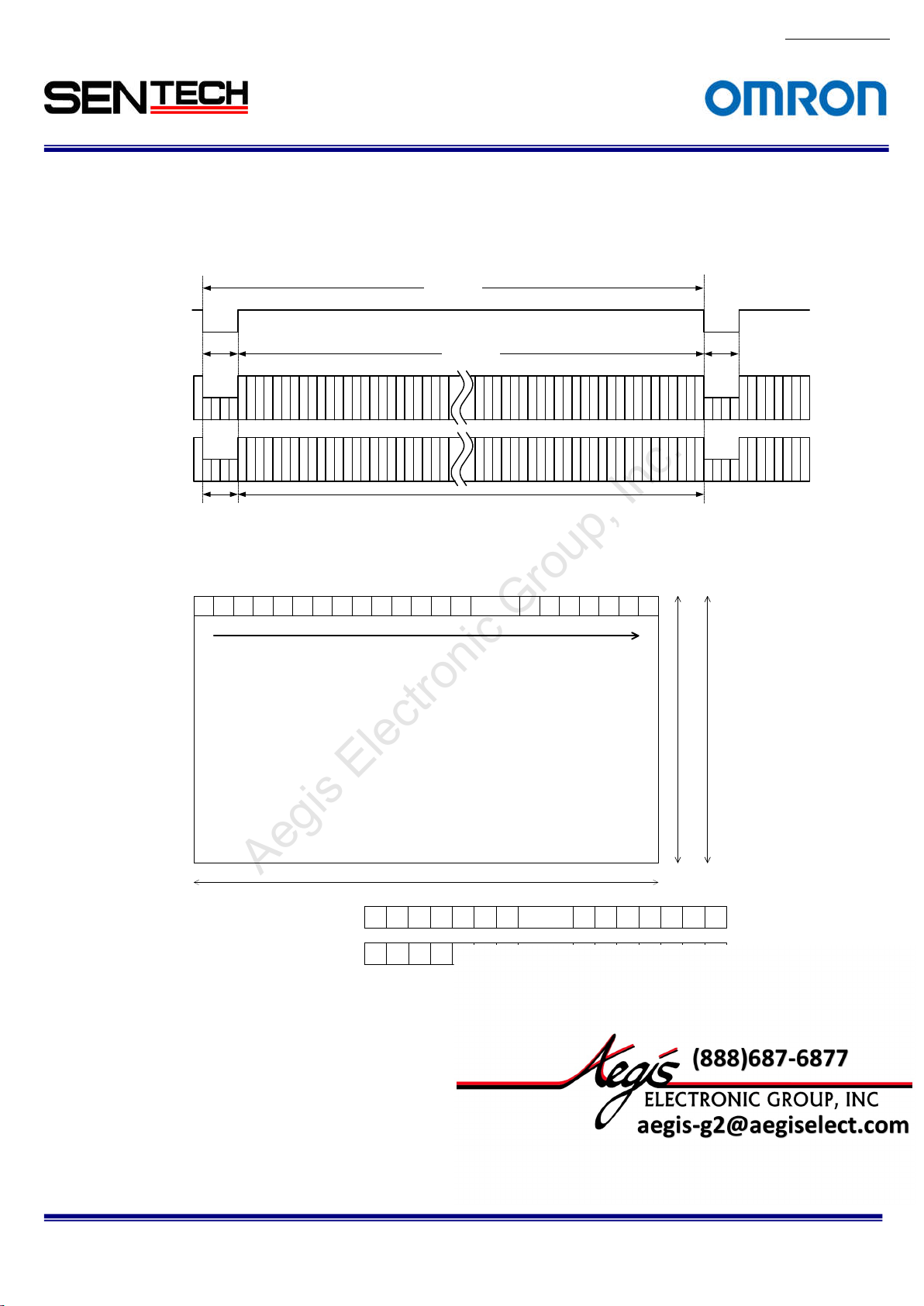
5.1.8
2Taps (1X2-1Y) / 2 x 2 Binning
LVAL
Video out
(Tap 1: DA)
Video out
(T
ap 2: DB)
The pixel order for the Image
1+2 3+4
5+6 7+8 ......
TAP1: DA output pixels
TAP2: DB output pixels
1,032
520 CLK
Horizontal blanking
9+10 11+12 13+14 15+16 17+18 19+20 21+2 2 23+24 25+26 27+28
pixels
1,024
1+2 5+6 9+10 13+14 ......
3+4 7+8 11+12 15+16 ......
CLK
1+2
5+6
9+10
3+4
7+8
11+12
17+18 21+22 25+26
19+20 23+24 27+28
1 CLK = 11.764 nseconds(85MHz)
1 CLK = 23.524 nseconds(42.5MHz)
One horizontal (1H)
512 CLK
Video output
2035+
2037+
2039+
38
40
2036
20
20
2041+
20
2021+
20
2023+
20
2043+
2045+
20
2025+
20
2027+
20
2047+
44
6
8
204
204
2029+
2033+
2037+
20
20
2031+
20
20
30
34
38
2035+
2039+
32
36
40
20
20
26
28
42
22
24
+2038
2037
2039+2040
2,048 l
ines (STC-CMB4MCL/CMC4MCL)
2041+
20
2043+
20
2041+2042
2045+2046
2043+2044
2047+2048
42
44
1,088 l
ines (STC-CMB2MCL/CMC2MCL)
2045+
20
2047+
20
46
48
520 CLK
No.13S0
80-10
STC-CMB200P
CL / STC-CMC200PCL / STC-CMB401PCL / STC-CMC401PCL
Specifications and Users guide
Page 29

29
For more information please contact Aegis Electronic Group, Inc. *(888)687-6877 *aegis-g2@aegiselect.com *http://www.aegiselect.com
Aegis Electronic Group, Inc.
5.1.9
4Taps (1X4-1Y) / 2 x 2 Binning
LVAL
Video o
(Tap 1: DA)
ut
Video o
(Tap 2: DB)
ut
Video o
ut
(Tap 3: DC)
Video out
(Tap 4: DD)
The pixel order for the Image
TAP1: DA output pixels
TAP2: DB output pixels
TAP3: DC output pixels
TAP4: DD output pixels
1 CLK = 11.764 nseconds(85MHz)
1 CLK = 23.524 nseconds(42.5MHz)
K
516 CL
260 CLK
519
6
2
10
7
3
11
8
4
12
Horizon
tal blanking
1-1 1-2
1 5 9 13 ...... 99717 21 25 1001 1005 1009 1013 1017 1021
2 6 10 14 ...... 99818 22 26 1002 1006 1010 1014 1018 1022
3 7 11 15 ...... 99919 23 27 1003 1007 1011 1015 1019 1023
4 8 12 16 ...... 100020 24 28 1004 1008 1012 1016 10 20 1024
1-4
1-3
2-22-1
2-4
2-3
1024
・・・
・・・
pixels
1-2045
2-2045
256 CLK
Video output
046
1-2048
1-2047
1-2
2-2048
2-2047
2-2
046
One horizontal (1H)
1024 lines
No.13S0
80-10
260 CLK
1021
1017
1013
1022
1018
1014
1023
1019
1015
1024
1020
1016
STC-CMB200P
CL / STC-CMC200PCL / STC-CMB401PCL / STC-CMC401PCL
Specifications and Users guide
Page 30

30
For more information please contact Aegis Electronic Group, Inc. *(888)687-6877 *aegis-g2@aegiselect.com *http://www.aegiselect.com
Aegis Electronic Group, Inc.
5.1.10
2Taps (1X2-1Y) / 4 x 4 Binning
LVAL
Video out
ap 1: DA)
(T
Video out
(Tap 2: DB)
The pixel order for the Image
TAP1: DA output pixels
TAP2: DB output pixels
776 CLK
Horizontal blanking
1-5 1-6
1-1 1-2
1-4
1-3
2-6
2-5 2-8
2-2
2-1 2-4
2-3
3-63-5 3-83-7
3-23-1 3-43-3
4-5
4-2 4-4
4-3
4-6 4-8
4-1
1 3 5 7 ...... 4999 11 13 501 503 505 507 509 51 1
2 4 6 8 ...... 50010 12 14 502 504 506 508 510 512
1-7
2-7
4-7
1-8
1,032 CL
315
426
・・・
・・・
512 pixels
K
1 CLK = 11.764 nseconds(85MHz)
1 CLK = 23.524 nseconds(42.5MHz)
One horizontal (1H)
256 CLK
511
509
507
512
510
508
Video output
1-
1-
1-
1-
1-
20421-2044
2041
2-
2-
20422-2044
2041
3-
20413-20423-2043
4-
20414-20424-2044
1-
1-
6
7
204
2048
2045
204
2043
2-
2-
2-
2-
2-
204
2048
2045
204
2043
6
7
3-
3-
3-
2048
20453-20463-2047
2044
4-
4-
4-
4-
6
20454-204
2048
2047
2043
512 lines
776 CLK
No.13S0
80-10
STC-CMB200P
CL / STC-CMC200PCL / STC-CMB401PCL / STC-CMC401PCL
Specifications and Users guide
Page 31

31
For more information please contact Aegis Electronic Group, Inc. *(888)687-6877 *aegis-g2@aegiselect.com *http://www.aegiselect.com
Aegis Electronic Group, Inc.
5.1.11
1Taps (1X-1Y) / 8 x 8 Binning
LVAL
Video ou
(Tap 1: DA)
t
The pixel order for the Image
TAP1: DA output pixels
2,064 CLK
1-
1-
・・・
2041
2-
2-
・・・
2041
・・・
・・・
・・・
8-
・・・
20418-20428-2048
256 CLK
Video output
1-
・・・
20421-2048
2-
・・・
20422-2048
・・・
・・・
・・・
1,808 CLK
213
Horizonta
l blanking
1-1 1-2
1-8
・・・
1-9 1-10
1-16
・・・
・・・
2-10
2-9 2-16
・・・
・・・
8-9
8-10 8-16
・・・
・・・
・・・
・・・
・・・
256
・・・
・・・
pixels
2-2
2-1 2-8
・・・
・・・
8-1
8-2 8-8
1 2 3 4 ...... 2505 6 7 251 252 253 254 255 256
1-
20341-2040
2033
2-
20342-2040
2033
・・・
8-
20338-20348-2040
No.13S0
1 CLK = 11.764 nseconds(85MHz)
1 CLK = 23.524 nseconds(42.5MHz)
One horizontal (1H)
1,808 CLK
256
255
254
256 lines
80-10
STC-CMB200P
CL / STC-CMC200PCL / STC-CMB401PCL / STC-CMC401PCL
Specifications and Users guide
Page 32

32
For more information please contact Aegis Electronic Group, Inc. *(888)687-6877 *aegis-g2@aegiselect.com *http://www.aegiselect.com
Aegis Electronic Group, Inc.
5.1.12
2 Taps (1X2-1Y)/2 x 2 Subsampling
LVAL
4 CLK
Video out
ap1: DA)
(T
315
Video out
(Tap2: DB)
426
Horizo
blanking
ntal
The pixel order for the Image
TAP1: DA output pixels
TAP2: DB output pixels
1 CLK = 11.764 nseconds(85MHz)
1 CLK = 23.524 nseconds(42.5MHz)
K
516 CL
K
512 CL
Video output
1024
・・・
・・・
pixels
1-2045 1-2047
3-2045 3-2047
1-1 1-3
3-1 3-3
1 3 5 7 ...... 10119 11 13 1013 1015 10 17 1019 1021 1023
2 4 6 8 ...... 101210 12 14 1014 1016 1018 1020 1022 1024
One horizontal (1H)
1024
lines
No.13S0
80-10
4 CLK
1023
1021
1019
1024
1022
1020
STC-CMB200P
CL / STC-CMC200PCL / STC-CMB401PCL / STC-CMC401PCL
Specifications and Users guide
Page 33

33
blank
ing
For more information please contact Aegis Electronic Group, Inc. *(888)687-6877 *aegis-g2@aegiselect.com *http://www.aegiselect.com
Aegis Electronic Group, Inc.
5.1.13
4 Taps (1X4-1Y) / 2 x 2 Subsampling
LVAL
2 CLK
Video out
(T
ap1: DA)
159
Video out
(Tap2: DB)
2
6
Video out
(Tap3: DC)
3
7
Video out
(Tap4: DD)
4
8
Horizonta
l
The pixel order for the Image
TAP1: DA output pixels
TAP2: DB output pixels
TAP3: DC output pixels
TAP4: DD output pixels
No.13S0
80-10
1 CLK = 11.764 nseconds(85MHz)
1 CLK = 23.524 nseconds(42.5MHz)
258 CL
K
256 CLK
10
11
12
Video
output
1024 p
・・・
・・・
ixels
1-2045 1-2047
3-2045 3-2047
1-1 1-3
3-1 3-3
1 5 9 13 ...... 99717 21 25 1001 1005 1009 1013 1017 1021
2 6 10 14 ...... 99818 22 26 1002 1006 1010 1014 1018 1022
3 7 11 15 ...... 99919 23 27 1003 1007 1011 1015 1019 1023
4 8 12 16 ...... 100020 24 28 1004 1008 1012 1016 10 20 1024
One horizontal (1H)
1024
lines
2 CLK
1013
1017
1021
22
1014
1018
10
1015
1019
1023
1016
1020
1024
STC-CMB200P
CL / STC-CMC200PCL / STC-CMB401PCL / STC-CMC401PCL
Specifications and Users guide
Page 34

34
For more information please contact Aegis Electronic Group, Inc. *(888)687-6877 *aegis-g2@aegiselect.com *http://www.aegiselect.com
Aegis Electronic Group, Inc.
5.1.14
2 Taps (1X2-1Y) / 4 x 4 Subsampling
LVAL
2 CLK
Video out
ap1: DA)
(T
315
Video out
ap2: DB)
(T
426
Horizo
blanking
ntal
The pixel order for the Image
TAP1: DA output pixels
TAP2: DB output pixels
1 CLK = 11.764 nseconds(85MHz)
1 CLK = 23.524 nseconds(42.5MHz)
K
258 CL
256 CLK
Video output
1-1 1-5
5-1 5-5
1 3 5 7 ...... 4999 11 13 501 503 505 507 509 51 1
2 4 6 8 ...... 50010 12 14 502 504 506 508 510 512
・・・
・・・
512 pixels
1-2041 1-2045
5-2041 5-2045
One horizontal (1H)
512
lines
No.13S0
80-10
2 CLK
511
509
507
512
510
508
STC-CMB200P
CL / STC-CMC200PCL / STC-CMB401PCL / STC-CMC401PCL
Specifications and Users guide
Page 35

35
For more information please contact Aegis Electronic Group, Inc. *(888)687-6877 *aegis-g2@aegiselect.com *http://www.aegiselect.com
Aegis Electronic Group, Inc.
5.1.15
1 Taps (1X-1Y)/8 x 8 Subsampling
LVAL
2 CLK 2 CLK
Video ou
(Tap1: DA)
t
213
Horizontal
blanking
The pixel order for the Image
TAP1: DA output pixels
1 CLK = 11.764 nseconds(85MHz)
1 CLK = 23.524 nseconds(42.5MHz)
K
258 CL
256 C
LK
Video output
1-1 1-9
9-1 9-9
1 2 3 4 ...... 2505 6 7 251 252 253 254 255 256
・・・
・・・
256 pixels
One horizontal (1H)
1-2033 1-2041
9-2033 9-2041
256 lines
No.13S0
80-10
256
255
254
STC-CMB200P
CL / STC-CMC200PCL / STC-CMB401PCL / STC-CMC401PCL
Specifications and Users guide
Page 36

36
For more information please contact Aegis Electronic Group, Inc. *(888)687-6877 *aegis-g2@aegiselect.com *http://www.aegiselect.com
Aegis Electronic Group, Inc.
5.2 The Vertical ti
As for Horizontal timing, please refer to the
The horizontal timings (STC-CMB/CMC200PCL, CMB/CMC401PCL)
Three V
mings
ideo scan modes exist. The detail for these three scan modes are described as below.
Full scan: All of line and pixel output from the camera
Binning: Averaged pixel value output from the camera
Subsampling: Skipped the lines and pixels output from the camera
Overview of Full scan
the lines and pixels are output and the entire image is shown. For transmitting the image,
All of
some configurations will not be supported, or can drop the frame rate..
Output im
image from Sensor on Fullscan (STC-CMB2MCL/CMC2MCL)
Output
Output image from Sensor on Fullscan (STC-CMB4MCL/CMC4MCL)
Overvie
age from Sensor on 2 x2 binning Output image from Sensor on 4 x4 binning Output image from Sensor on 8 x 8 binning
w of Binning (2M,4M)
verage pixel value is output and shown in the image. For average pixel data, decreasing the noise
The a
level. This binning does not add the pixel value, but instead increases the black level (this means
narrow dynamic range). For this, the resolution will decrease and frame rate will increase.
No.13S0
80-10
STC-CMB200P
CL / STC-CMC200PCL / STC-CMB401PCL / STC-CMC401PCL
Specifications and Users guide
Page 37

37
For more information please contact Aegis Electronic Group, Inc. *(888)687-6877 *aegis-g2@aegiselect.com *http://www.aegiselect.com
Aegis Electronic Group, Inc.
Overvie
Output im
age from Sensor on 2 x2 subsampling Output image from Sensor on 4 x4subsampling Output image from Sensor on 8 x 8 subsampling
w of Subsampling (2M,4M)
In Subsampling mode, lines and pixel values skip, then are output in the shown image. For skipped
pixel data, the resolution will decrease while the frame rate increases. Subsampling reduces the output
resolution and increases the frame rate without the FOV (Field of View).
No.13S0
80-10
STC-CMB200P
CL / STC-CMC200PCL / STC-CMB401PCL / STC-CMC401PCL
Specifications and Users guide
Page 38

38
For more information please contact Aegis Electronic Group, Inc. *(888)687-6877 *aegis-g2@aegiselect.com *http://www.aegiselect.com
Aegis Electronic Group, Inc.
5.2.1
Full Scan (STC-CMB/CMC200PC)
VAL
F
1
2
Video out
blanking
Configuration Camer
Frequency(MHz)
*1: 94H o
Table o
Mode
(EEH)
Vertical
nly on 2TAP, 42.5MHz mode
f Video Output on Full Scan mode (STC-CMB/CMC200PCL)
Tap
Numbe
r
aLink Output
PixelCloc
k
1116 H
Horizon
1088 H28H *1
Video
(Pixel)
output
tal Pixel
One vertical (1V)
Sensor Output P
Clock(MHz)
ixel
28 H *1
1087
1088
FPS Camer
No.13S0
a Link
Output Bit
80-10
0 2 Base 85.0 2048 10.625 73.8 8/10
5 2 Base 85.0 1024 21.250 147.6
6 2 Base 85.0 512 42.500
1 4 MEDIUM 85.0 2048 21.250 147.6
7 4 MEDIUM 85.0 1024 42.500
2 8 FULL 85.0 2048 42.500
3 10 80.0 2040 48.000
0 2 Base 42.5 2048 5.313 34.8 8/10
5 2 Base 42.5 1024 10.625 73.8 8/10
6 2 Base 42.5 512 21.250 147.6
1 4 MEDIUM 42.5 2048 10.625 73.8 8/10
7 4 MEDIUM 42.5 1024 21.250 147.6
2 8 FULL 42.5 2048 21.250 147.6
3 10 40.0 2040 24.000 166.7
295.2
295.2
295.2
333.4
8/10
8/10
8/10
8/10
8
8
8/10
8/10
8
8
STC-CMB200P
Specifications and Users guide
CL / STC-CMC200PCL / STC-CMB401PCL / STC-CMC401PCL
Page 39

39
For more information please contact Aegis Electronic Group, Inc. *(888)687-6877 *aegis-g2@aegiselect.com *http://www.aegiselect.com
Aegis Electronic Group, Inc.
5.2.2
Full Scan (STC-CMB/CMC401PCL)
VAL
F
28 H *1
Video out
Vertical blanking
*1: 94H o
nly on 2TAP, 42.5MHz mode
Table o
f Video Output on Full Scan mode (STC-CMB/CMC401PCL)
Mode
(EEH)
0 2 Base 85.0 2048 10.625 39.7 8/10
5 2 Base 85.0 1024 21.250 79.3 8/10
6 2 Base 85.0 512 42.500
1 4 Medium 85.0 2048 21.250 79.3 8/10
7 4 Medium 85.0 1024 42.500 158.7
2 8 Full 85.0 2048 42.500
3 10 80.0 2040 48.000
0 2 Base 42.5 2048 5.313 19.2
5 2 Base 42.5 1024 10.625 39.7 8/10
6 2 Base 42.5 512 21.250 79.3 8/10
1 4 Medium 42.5 2048 10.625 39.7 8/10
7 4 Medium 42.5 1024 21.250 79.3 8/10
2 8 Full 42.5 2048 21.250 79.3 8
3 10 40.0 2040 24.000 89.6 8
Tap
Numbe
Configuration Camer
r
1
2
aLink Output
PixelCloc
Frequency(MHz)
k
2,076
H
2,048
Video output
tal Pixel
Horizon
(Pixel)
No.13S0
80-10
One vertical (1V)
H
Sensor Output P
Clock(MHz)
ixel
28 H *1
2047
2048
FPS Camer
158.7
158.7
179.2
a Link
Output Bit
8/10
8/10
8
8
8/10
STC-CMB200P
Specifications and Users guide
CL / STC-CMC200PCL / STC-CMB401PCL / STC-CMC401PCL
Page 40

40
For more information please contact Aegis Electronic Group, Inc. *(888)687-6877 *aegis-g2@aegiselect.com *http://www.aegiselect.com
Aegis Electronic Group, Inc.
5.2.3
5.2.4
2 x 2 Binning (STC-CMB/CMC200PCL)
FVAL
Video ou
4 x 4 Binning (STC-CMB/CMC200PCL)
t
Vertical
nking
bla
FVAL
Video ou
t
blanking
Vertic
al
5.2.5 8 x 8 Binning (STC-CMB/CMC200PCL)
FVAL
Video ou
t
blanking
Vertic
al
558 H
Video
279 H
Video
139.5
Video
544 H14 H
272 H7H
136 H3.5 H
output
output
H
output
vertical (1V)
One
vertical (1V)
One
One vertical (1V)
14H
7 H
3.5 H
No.13S0
80-10
STC-CMB200P
CL / STC-CMC200PCL / STC-CMB401PCL / STC-CMC401PCL
Specifications and Users guide
Page 41

41
For more information please contact Aegis Electronic Group, Inc. *(888)687-6877 *aegis-g2@aegiselect.com *http://www.aegiselect.com
Aegis Electronic Group, Inc.
Table o
f Video Output on Binning mode (STC-CMB/CMC200PCL)
Averaged the pixels data is used for Binning mode. It makes decreasing the noise level and increasing
the Signal Noise Ratio. This camera has row and column binning modes. This mode can not increase the
frame rate.
Mode
(EEH)
8 2 2 x 2 Base 85.0 1024 21.250 147.6 8/10
10 2 4 x 4 Base 85.0 512 42.500
9 4 2 x 2 Medium 85.0 1024 42.500 295.2 8/10
11 1 8 x 8 Base 85.0 256 42.500
8 2 2 x 2 Base 42.5 1024 10.625 73.8 8/10
10 2 4 x 4 Base 42.5 512 21.250 147.6 8/10
9 4 2 x 2 Medium 42.5 1024 21.250 147.6 8/10
11 1 8 x 8 Base 42.5 256 21.250 147.6 8/10
8 2 2 x 2 Base 85.0 1024 21.250 147.6 8/10
Tap
Numbe
Binning Configuration CameraLink Output
r
PixelCloc
Frequency(
k
MHz)
Horizontal
(Pixel)
Pixel
Sensor
Output Pixel
Clock(MHz)
No.13S0
FPS Camera
Link Output
Bit
295.2 8/10
295.2 8/10
80-10
STC-CMB200P
CL / STC-CMC200PCL / STC-CMB401PCL / STC-CMC401PCL
Specifications and Users guide
Page 42

42
For more information please contact Aegis Electronic Group, Inc. *(888)687-6877 *aegis-g2@aegiselect.com *http://www.aegiselect.com
Aegis Electronic Group, Inc.
5.2.6
5.2.7
5.2.8
2 x 2 Subsampling (STC-CMB/CMC200PCL)
FVAL
Video ou
4 x 4 Subsampling (STC-CMB/CMC200PCL)
t
Vertical blanking
FVAL
Video ou
8 x 8 Subsampling (STC-CMB/CMC200PCL)
t
Vertical blanking
FVAL
Video ou
t
Vertical blanking
566 H
Video output
296 H
Video output
158 H
Video output
No.13S0
80-10
One
vertical (1V)
544 H28 H
One
vertical (1V)
274 H28 H
One
vertical (1V)
136 H28 H
28H
28 H
28 H
STC-CMB200P
CL / STC-CMC200PCL / STC-CMB401PCL / STC-CMC401PCL
Specifications and Users guide
Page 43

43
For more information please contact Aegis Electronic Group, Inc. *(888)687-6877 *aegis-g2@aegiselect.com *http://www.aegiselect.com
Aegis Electronic Group, Inc.
Table o
f Video Output on Subsampling mode (STC-CMB/CMC200PCL)
Subsampling reduce the output resolution and increase the frame rate.without FOV(Field of View). This
camera has row and column subsampling modes. This mode can not reduce the noise level.
Mode
(EEH)
12 2 2 x 2 Base 85.0 1024 21.250 288.0 8/10
14 2 4 x 4 Base 85.0 512 42.500
13 4 2 x 2 Medium 85.0 1024 42.500
15 1 8 x 8 Base 85.0 256 42.500
12 2 2 x 2 Base 42.5 1024 10.625 144.0 8/10
14 2 4 x 4 Base 42.5 512 21.250 549.1 8/10
13 4 2 x 2 Medium 42.5 1024 21.250 288.0 8/10
15 1 8 x 8 Base 42.5 256 21.250 1004.4
Tap
Numbe
Binning Configuration Camer
r
aLink Output
PixelCloc
Frequency(
k
MHz)
tal
Horizon
Pixel (Pixel)
Sensor
Output Pixel
Clock(MHz
FPS Camer
)
1098.2
576.0 8/10
2008.9
No.13S0
a
Link Output
Bit
8/10
8/10
8/10
80-10
STC-CMB200P
CL / STC-CMC200PCL / STC-CMB401PCL / STC-CMC401PCL
Specifications and Users guide
Page 44

44
For more information please contact Aegis Electronic Group, Inc. *(888)687-6877 *aegis-g2@aegiselect.com *http://www.aegiselect.com
Aegis Electronic Group, Inc.
5.2.9
5.2.10
5.2.11
2 x 2 Binning (STC-CMB/CMC401PCL)
FVAL
14 H
Video ou
t
Vertical
blanking
4 x 4 Binning (STC-CMB/CMC401PCL)
FVAL
Video out
Vertic
al
blanking
8 x 8 Binning (STC-CMB/CMC401PCL)
FVAL
Video ou
t
blanking
Vertic
al
1,038 H
1,024
Video
579 H
Video
259.5
256 H3.5 H
Video
572 H7 H
H
H
output
output
output
One vertical (1V)
vertical (1V)
One
One vertical (1V)
14 H
7 H
3.5 H
No.13S0
80-10
STC-CMB200P
CL / STC-CMC200PCL / STC-CMB401PCL / STC-CMC401PCL
Specifications and Users guide
Page 45

45
For more information please contact Aegis Electronic Group, Inc. *(888)687-6877 *aegis-g2@aegiselect.com *http://www.aegiselect.com
Aegis Electronic Group, Inc.
Table o
f Video Output on Binning mode (STC-CMB/CMC401PCL)
Averaged the pixels data is used for Binning mode. It makes decreasing the noise level and increasing
the Signal Noise Ratio. This camera has row and column binning modes. This mode can not increase the
frame rate.
Mode
(EEH)
8 2 2 x 2 Base 85.0 1024 21.250 79.3 8/10
10 2 4 x 4 Base 85.0 512 42.500
9 4 2 x 2 Medium 85.0 1024 42.500
11 1 8 x 8 Base 85.0 256 42.500
8 2 2 x 2 Base 42.5 1024 10.625 39.7 8/10
10 2 4 x 4 Base 42.5 512 21.250 79.3 8/10
9 4 2 x 2 Medium 42.5 1024 21.250 79.3 8/10
11 1 8 x 8 Base 42.5 256 21.250 79.3 8/10
Tap
Numbe
Binning Configuration Camer
r
aLink Output
PixelCloc
Frequency(
k
MHz)
Horizon
Pixel (Pixel)
tal
Sensor
Output Pixel
Clock(MHz
FPS Camer
)
158.7 8/10
158.7 8/10
158.7 8/10
No.13S0
a
Link Output
Bit
80-10
STC-CMB200P
CL / STC-CMC200PCL / STC-CMB401PCL / STC-CMC401PCL
Specifications and Users guide
Page 46

46
For more information please contact Aegis Electronic Group, Inc. *(888)687-6877 *aegis-g2@aegiselect.com *http://www.aegiselect.com
Aegis Electronic Group, Inc.
5.2.12
2 x 2 Subsampling (STC-CMB/CMC401PCL)
FVAL
Video ou
t
Vertical blanking
5.2.13 4 x 4 Subsampling (STC-CMB/CMC401PCL)
5.2.14
FVAL
Video ou
8 x 8 Subsampling (STC-CMB/CMC401PCL)
t
Verti
cal blanking
FVAL
Video ou
t
Vertical blanking
1,052
540 H
284 H
H
1,024 H28 H
Video output
512 H28 H
Video
output
256 H28 H
Video output
One vertical (1V)
vertical (1V)
One
One vertical (1V)
28 H
28 H
28 H
No.13S0
80-10
STC-CMB200P
CL / STC-CMC200PCL / STC-CMB401PCL / STC-CMC401PCL
Specifications and Users guide
Page 47

47
For more information please contact Aegis Electronic Group, Inc. *(888)687-6877 *aegis-g2@aegiselect.com *http://www.aegiselect.com
Aegis Electronic Group, Inc.
Table o
f Video Output on Subsampling mode(STC-CMB/CMC401PCL)
Subsampling reduce the output resolution and increase the frame rate.without FOV(Field of View). This
camera has row and column subsampling modes. This mode can not reduce the noise level.
Mode
(EEH)
12 2 2 x 2 Base 85.0 1024 21.250 156.6 8/10
14 2 4 x 4 Base 85.0 512 42.500
13 4 2 x 2 Medium 85.0 1024 42.500 313.2 8/10
15 1 8 x 8 Base 85.0 256 42.500
12 2 2 x 2 Base 42.5 1024 10.625 78.3 8/10
14 2 4 x 4 Base 42.5 512 21.250 305.1 8/10
13 4 2 x 2 Medium 42.5 1024 21.250 156.6 8/10
15 1 8 x 8 Base 42.5 256 21.250 580.0 8/10
Tap
Numbe
Binning Configuration CameraLink Output
r
PixelCloc
Frequency(
k
MHz)
Horizontal
Pixel (Pixel)
Sensor
Output Pixel
Clock(MHz
FPS Camera
)
610.1 8/10
1160.1
No.13S0
Link Output
Bit
8/10
80-10
STC-CMB200P
CL / STC-CMC200PCL / STC-CMB401PCL / STC-CMC401PCL
Specifications and Users guide
Page 48

48
For more information please contact Aegis Electronic Group, Inc. *(888)687-6877 *aegis-g2@aegiselect.com *http://www.aegiselect.com
Aegis Electronic Group, Inc.
5.3 ROI Output
This camera can be set the ROI up to 8.
ROI can be set the Binning and Subsampling at the same time.
Setting of The horizontal effective pixel and the horizontal effective pixels of changeable
DVAL are different form each Cameralink output TAP number.
The horizontal ROI can be controlled by LVAL and DVAL. The Video signal output directly.
Therefore frame rate cannot increase on this mode.
Timing
204
90
-91h
No.13S0
80-10
8
VASA
HAWA
C0-C1h
HASA
h
B0-B1
2048
HASB
B2-B3h
B4-B5
HASC
HASD
B6-B7
h
h
ROI_A
AOI_A
C2-C3h
ROI_B
AOI_B
HAWB
A0-
A1h
92-93h
VAHA
A2-A3h
HAWC
C4-C5h
AOI_C
ROI_C
HAWD
C6-C7h
AOI_D
ROI_D
VASB
9
VASC
4-95h
96-97h
VASD
VAHB
A4-
VAHC
A5h
A6-A7h
VAHD
STC-CMB200P
CL / STC-CMC200PCL / STC-CMB401PCL / STC-CMC401PCL
Specifications and Users guide
Page 49

No.13S0
49
For more information please contact Aegis Electronic Group, Inc. *(888)687-6877 *aegis-g2@aegiselect.com *http://www.aegiselect.com
Aegis Electronic Group, Inc.
80-10
The horizontal effective pixel
Register[4CH
Register[4EH,4FH2-0]=H_NUMBER: Horizontal available pixel number / Output TAP number / Binning or Subsampling number
Register[4
,4DH2-0]=H_STRAT: Horizontal start position / Output TAP number / Binning or Subsampling number
The horizon
When u
EH,4FH2-0]=(H_NUMBER: Horizontal available pixel number -4 ) / Output TAP number / Binning or Subsampling number
tal effective pixels of changeable DVAL
se the 10 TAP, horizontal pixel number is 2,040 pixels. using H_STRAT: Horizontal start position - 4.
ROI_A
AOI_A
LVAL
FVAL
RAT[15]=0
H_ST
FVAL
LVAL
DVAL
ROI_B
AOI_B
ROI_D
AOI_D
ROI_C
AOI_C
LVAL
LVAL
LVAL
H_STRAT[15]=1
FVAL
LVAL
DVAL
STC-CMB200P
Specifications and Users guide
CL / STC-CMC200PCL / STC-CMB401PCL / STC-CMC401PCL
Page 50

50
For more information please contact Aegis Electronic Group, Inc. *(888)687-6877 *aegis-g2@aegiselect.com *http://www.aegiselect.com
Aegis Electronic Group, Inc.
5.4 Camera Lin
k bit assignment
2TAP8
bit
XCLK
X3
2
X
X1
X0
DA0 to D
DA6DA7
NCNC
DB1DB2
DA1 DA0
A7: 8bit data for one pixel from TAP1
DB0 to DB7: 8bit data for one pixel from TAP2
2TAP1
0bit
XCLK
X3
DA6DA7
2
X
DB2DB3
DA9
X1
NC
X0
DA1 DA0
DA0 to DA9
: 10bit data for one pixel from TAP1
DB0 to DB9: 10bit data for one pixel from TAP2
SP DA6DA7DB6DB7
NC NC
LVALFVALDVAL
NC NC NC
NC
NC
DA5 DA4 DA3 DA2 DA1 DA0DB0
SP DA6DA7DB6DB7
DA8 DA5 DA4 DA3 DA2 DA1 DA0
NC NC
NC
NC NC
DB1DB2DB3DB4DB5
DB2DB3DB4DB5LVALFVALDVAL
DA9DB8DB9DB0DB1 DB8DB9
No.13S0
80-10
STC-CMB200P
CL / STC-CMC200PCL / STC-CMB401PCL / STC-CMC401PCL
Specifications and Users guide
Page 51

51
For more information please contact Aegis Electronic Group, Inc. *(888)687-6877 *aegis-g2@aegiselect.com *http://www.aegiselect.com
Aegis Electronic Group, Inc.
4TAP8b
XCLK
it
4TAP10
XCLK
bit
X3
SP DA6DA7DB6DB7
DA6DA7
DC6DC7
X3
DA6DA7
SP DA6DA7DB6DB7
NC NC
2
X
DC2DC3
LVALFVALDVAL
DC5 DC4 DC3 DC2
X
2
DB2DB3
X1
X0
YCLK
Y3
Y2
Y1
Y0
DB1DB2
DA1 DA0
DD6DD7
DF2DF3
DE1DE2
DD0DD1
DC1 DC0
DA5 DA4 DA3 DA2 DA1 DA0DB0
SP DD6DD7
NC NC NC NC
LVALFVALDVAL
NC NC NC NC
NC NC NC NC NC NC NC
NC
DB1DB2DB3DB4DB5
DD0DD1DD2DD3DD4DD5
X1
X0
YCLK
Y3
Y2
Y1
Y0
DA9
NC
DA1 DA0
DD6DD7
NC NC
DC1
DC2
DD0DD1
NC NC
DA8 DA5 DA4 DA3 DA2 DA1 DA0
SP DC6DC7 DD6DD7
NC NC
LVALFVALDVAL
DC8 DC5 DC4 DC3 DC2 DC1
DC9
DC0
DD8DD9
DA0 to DA7: 8bit data for one pixel from TAP1 DA0 to DA9: 10bit data for one pixel from TAP1
DB0 to DB7: 8bit data for one pixel from TAP2 DB0 to DB9: 10bit data for one pixel from TAP2
DC0 to DC7: 8bit data for one pixel from TAP3 DC0 to DC9: 10bit data for one pixel from TAP3
DD0 to DD7: 8bit data for one pixel from TAP4 DD0 to DD9: 10bit data for one pixel from TAP4
No.13S0
NC NC
80-10
DB2DB3DB4DB5LVALFVALDVAL
DA9DB8DB9DB0DB1 DB8DB9
DD0DD1DD2DD3DD4DD5
STC-CMB200P
CL / STC-CMC200PCL / STC-CMB401PCL / STC-CMC401PCL
Specifications and Users guide
Page 52

52
For more information please contact Aegis Electronic Group, Inc. *(888)687-6877 *aegis-g2@aegiselect.com *http://www.aegiselect.com
Aegis Electronic Group, Inc.
8TAP8
bit
XCLK
X3
DA6DA7
X2
X1
X0
YCLK
Y3
Y2
Y1
Y0
ZCLK
Z3
Z2
Z1
Z0
DA0 to D
DC2DC3
DB1DB2
DA1 DA0
DF2DF3
DE1DE2
DD0DD1
NCNC NC NC NC NC
DH1DH2
DG0DG1
A7: 8bit data for one pixel from TAP1
DB0 to DB7: 8bit data for one pixel from TAP2
DC0 to DC7: 8bit data for one pixel from TAP3
DD0 to DD7: 8bit data for one pixel from TAP4
DE0 to DE7: 8bit data for one pixel from TAP5
DF0 to DF7: 8bit data for one pixel from TAP6
DG0 to DG7: 8bit data for one pixel from TAP7
DH0 to DH7: 8bit data for one pixel from TAP8
SP DA6DA7DB6DB7
DC1 DC0
SP
DF1 DF0
DE0
SP DG6DG7
NC NC
DH0
LVALFVALDVAL
DA5 DA4 DA3 DA2 DA1 DA0DB0
LVALFVALDVAL
NC NC
LVALFVALDVAL
DC6DC7
DC5 DC4 DC3 DC2
DF6DF7
DE6DE7DD6DD7
DF5 DF4 DF3 DF2
DH6DH7DG6DG7
No.13S0
80-10
DB1DB2DB3DB4DB5
DD6DD7
DE1DE2DE3DE4DE5
DD0DD1DD2DD3DD4DD5
DH1DH2DH3DH4DH5
DG0DG1DG2DG3DG4DG5
STC-CMB200P
CL / STC-CMC200PCL / STC-CMB401PCL / STC-CMC401PCL
Specifications and Users guide
Page 53

53
For more information please contact Aegis Electronic Group, Inc. *(888)687-6877 *aegis-g2@aegiselect.com *http://www.aegiselect.com
Aegis Electronic Group, Inc.
10TAP8
bit
XCLK
X3
DA5
DD1
X2
X1
X0
YCLK
Y3
Y2
Y1
Y0
ZCLK
Z3
Z2
Z1
Z0
DA0 to D
DC3DC4
DB0DB1
DA1 DA0
LVALDD7
DF5DF6
DE2DE3
DD2DD3
DH2
LVAL
DJ0DJ1
DH5
DH6
DG5DG6 DH1
A7: 8bit data for one pixel from TAP1
DB0 to DB7: 8bit data for one pixel from TAP2
DC0 to DC7: 8bit data for one pixel from TAP3
DD0 to DD7: 8bit data for one pixel from TAP4
DE0 to DE7: 8bit data for one pixel from TAP5
DF0 to DF7: 8bit data for one pixel from TAP6
DG0 to DG7: 8bit data for one pixel from TAP7
DH0 to DH7: 8bit data for one pixel from TAP8
DI0 to DI7: 8bit data for one pixel from TAP9
DJ0 to DJ7: 8bit data for one pixel from TAP10
DC7
DD0
DC2
DG1
DF4
DE1
DJ4
DC1 DC0
LVALFVAL
DB6DB7
DA4 DA3 DA2 DA1 DA0
DA6DA7
DF3 DF2
DG2DG3DG4
DF1 DF0
DD6
DE0
DH3DH4
DB2DB3
DC5 DC4 DC3
DC6
DB4DB5
DE4DE5 LVAL
DE6DE7
DH7
DI0DI5DI6
DI1DI3DI4
DI2DI7
DH0
DA5
DD7
DF6DF7DG0
DH2
DJ1DJ3
DH6
DD1
DB0DB1
DF5
DE2DE3
DD2DD3DD4DD5
LVAL
DJ0DJ5DJ6 DJ2DJ7
DH5
DG5DG6DG7
No.13S0
80-10
STC-CMB200P
CL / STC-CMC200PCL / STC-CMB401PCL / STC-CMC401PCL
Specifications and Users guide
Page 54

54
For more information please contact Aegis Electronic Group, Inc. *(888)687-6877 *aegis-g2@aegiselect.com *http://www.aegiselect.com
Aegis Electronic Group, Inc.
5.5 Camera Lin
k TAP Geometry
5.5.1 2TAP (1X2-1Y)
Tap2
Tap1
No.13S0
80-10
Sep X
= 2
1
X
Y
X
Y
X
H-1
Y
Sep Y = 1
2
X
1
1
Y
1
2
X
2
2
Y
1
2
X
H-1
Y
W-1
X
Y
W-1
X
Y
W-1
X
Y
W
X
1
1
Y
W
X
2
2
Y
W
X
H-1
H-1
Y
5.5.2
4TAP (1X4-1Y)
Tap1
T
ap2
Tap3
Tap4
1
X
1
Y
1
X
2
Y
1
X
H-1
Y
Sep Y = 1
1
X
H
Y
X
Y
H
H
Y
2
1
X
W-1
X
Y
W
X
H
H
Y
Sep X =
4
2
3
X
X
1
Y
Y
2
X
X
2
Y
Y
2
X
X
H-1
Y
X
Y
H-1
Y
2
X
H
Y
4
X
1
1
Y
3
4
X
2
2
Y
3
4
X
H-1
Y
4
3
X
H
H
Y
W-3
W-2
W-2
W-2
H-1
W-2
W-1
X
1
Y
W-1
X
2
Y
W-1
X
H-1
Y
W-1
X
H
Y
X
X
1
Y
Y
W-3
X
X
2
Y
Y
W-3
X
X
H-1
Y
Y
W-3
X
X
H
Y
Y
W
X
1
1
Y
W
X
2
2
Y
W
X
H-1
Y
W
X
H
H
Y
STC-CMB200P
CL / STC-CMC200PCL / STC-CMB401PCL / STC-CMC401PCL
Specifications and Users guide
Page 55

55
For more information please contact Aegis Electronic Group, Inc. *(888)687-6877 *aegis-g2@aegiselect.com *http://www.aegiselect.com
Aegis Electronic Group, Inc.
5.5.3
Tap1
Tap2
Tap3
Tap4
Tap5
Tap6
Tap7
Tap8
Sep Y = 1
5.5.4
Tap1
Tap2
Tap3
Tap4
Tap5
Tap6
Tap7
Tap8
Tap9
Tap10
8TAP (1X8-1Y)
1
2
X
1
Y
1
X
2
Y
1
X
H-1
Y
1
X
H
Y
3
X
X
1
1
Y
Y
2
3
X
X
2
2
Y
Y
2
3
X
X
H-1
H-1
Y
Y
3
2
X
X
H
H
Y
Y
10TAP (1X10⁻¹Y)
X
X
X
1
2
Y
Y
1
1
X
X
1
2
Y
Y
2
2
X
3
4
Y
Y
1
1
X
X
3
4
Y
Y
2
2
No.13S0
80-10
Sep X = 8
W
W-1
W-2
W-3
W-4
W-5
W-6
4
X
1
Y
4
X
2
Y
4
X
H-1
Y
4
X
H
Y
X
X
5
Y
Y
1
X
X
5
Y
Y
2
6
7
X
X
5
1
Y
Y
1
6
X
X
5
2
Y
Y
2
6
5
X
X
H-1
H-1
Y
Y
6
5
X
X
H
H
Y
Y
X
6
1
6
2
X
7
8
Y
Y
1
1
X
X
7
8
Y
Y
2
2
8
X
X
1
1
Y
Y
7
8
X
X
2
2
Y
Y
8
7
X
X
H-1
H-1
Y
Y
8
7
X
X
H
H
Y
Y
X
X
9
10
Y
Y
1
1
X
X
9
10
Y
Y
2
2
W-7
X
X
1
1
Y
Y
W-6
W-7
X
X
2
2
Y
Y
W-7
W-6
X
X
H-1
H-1
Y
Y
W-6
W-7
X
X
H
H
Y
Y
X
X
1
1
Y
Y
W-4
W-5
X
X
2
2
Y
Y
W-5
W-4
X
X
H-1
H-1
Y
Y
W-4
W-5
X
X
H
H
Y
Y
X
X
1
1
Y
Y
W-2
W-3
X
X
2
2
Y
Y
W-3
W-2
X
X
H-1
H-1
Y
Y
W-2
W-3
X
X
H
H
Y
Y
X
X
1
1
Y
Y
W
W-1
X
X
2
2
Y
Y
W-1
W
X
X
H-1
H-1
Y
Y
W
W-1
X
X
H
H
Y
Y
Sep X =10
W
W-1
W-2
W-3
W-4
W-5
W-6
W-7
W-8
W-9
X
X
1
1
Y
Y
W-8
W-9
X
X
2
2
Y
Y
X
X
1
Y
Y
W-6
W-7
X
X
2
Y
Y
X
X
1
1
1
2
Y
Y
W-4
W-5
X
X
2
2
Y
Y
X
X
1
1
Y
Y
W-2
W-3
X
X
2
2
Y
Y
X
X
1
1
Y
Y
W
W-1
X
X
2
2
Y
Y
X
X
X
X
X
X
1
2
3
4
Y
Y
H-1
Sep Y =1
X
1
Y
H
Y
H-1
H-1
X
X
3
2
Y
Y
H
H
5
Y
Y
H-1
H-1
X
X
5
4
Y
Y
H
H
X
6
7
Y
Y
H-1
H-1
X
X
7
6
Y
Y
H
H
X
X
8
Y
H-1
X
8
Y
H
X
9
10
Y
Y
H-1
H-1
X
X
10
9
Y
Y
H
H
X
X
X
X
X
X
X
X
X
W-9
W-8
W-7
W-6
W-5
W-4
W-3
Y
Y
Y
Y
Y
H-1
H-1
H-1
H-1
W-8
X
X
W-9
Y
Y
H
H
X
X
W-6
W-7
Y
Y
H
H
Y
H-1
H-1
X
X
W-4
W-5
Y
Y
H
H
W-2
Y
Y
H-1
H-1
X
X
W-3
W-2
Y
Y
H
H
X
W-1
W
Y
Y
H-1
H-1
X
X
W-1
W
Y
Y
H
H
STC-CMB200P
CL / STC-CMC200PCL / STC-CMB401PCL / STC-CMC401PCL
Specifications and Users guide
Page 56

56
For more information please contact Aegis Electronic Group, Inc. *(888)687-6877 *aegis-g2@aegiselect.com *http://www.aegiselect.com
Aegis Electronic Group, Inc.
5.6 Bayer patt
ern for color model (Only STC-CMC200PCL / STC-CMC401PCL)
G
R
B G
G
R
No.13S0
80-10
B
G
STC-CMB200P
Specifications and Users guide
CL / STC-CMC200PCL / STC-CMB401PCL / STC-CMC401PCL
Page 57

57
For more information please contact Aegis Electronic Group, Inc. *(888)687-6877 *aegis-g2@aegiselect.com *http://www.aegiselect.com
Aegis Electronic Group, Inc.
6. Camera function modes
6.1. Norm
6.1.1.
al mode
Normal mode (Electronic shutter)
I nt
er na l VD
CC D
e x po su r e
Vi de o ou t
Ex p
os ur e
t i me
No.13S0
80-10
STC-CMB200P
CL / STC-CMC200PCL / STC-CMB401PCL / STC-CMC401PCL
Specifications and Users guide
Page 58

58
For more information please contact Aegis Electronic Group, Inc. *(888)687-6877 *aegis-g2@aegiselect.com *http://www.aegiselect.com
Aegis Electronic Group, Inc.
6.2 Pulse w
idth trigger mode
In this trigger mode with positive polarity, the camera exposure starts at the rising edge of the trigger pulse and
stops at the falling edge of the trigger pulse. Therefore, In the case of the exposure positive polarity is selected, the
exposure periods are the high states of the trigger pulse.
6.2.1
Pulse width trigger mode (V-Reset)
Note.1: T
he exposure time sets by the pulse width of the trigger signal.
6.2.2
Pulse width trigger mode (Exposure timing)
Trigg
er signal
Exposure time
Note.1: T
he trigger signal is removed by the filtering if the pulse width of the input trigger signal is less than 15us.
Please input the trigger signal has more than 1.0 us pulse width.
Note.2: α1(Exposure time offset) is different from using clock, TAP number.
Pulse Width:22[us]
Edge Preset:21[us]
Trigger signal
(Positive)
Internal
exposure
Video out
FVAL
1.0us
VD
ring *Note.1
Filte
*Note. 1
Exposure
time
Exposure t
T1
T1'
ime: T1' = T1 + α1 *Note2
No.13S0
80-10
STC-CMB200P
CL / STC-CMC200PCL / STC-CMB401PCL / STC-CMC401PCL
Specifications and Users guide
Page 59

59
For more information please contact Aegis Electronic Group, Inc. *(888)687-6877 *aegis-g2@aegiselect.com *http://www.aegiselect.com
Aegis Electronic Group, Inc.
6.3 Edge preset
trigger mode
In this trigger mode, the camera exposure starts at the rising edge of the trigger pulse or negative edge when
setting is “Trigger Polarity::Negative”, the camera exposure starts at the falling edge of the trigger pulse.
Exposure duration time is preset by the “Electrical Shutter” settings.
.
6.3.1
Edge preset trigger mode (V-Reset)
Note.1: T
he exposure time sets by the preset electronic shutter speed.
Note 2. The horizontal two lines noise is appeared on the image when Trigger signal is input while the image
output period. In this case, trigger input after video out or set usec unit on exposure time setting unit.
6.3.2
Edge preset trigger mode (Exposure timing)
Tri
gger signal
Exposure time
Note.1: T
he trigger signal is removed by the filtering if the pulse width of the input trigger signal is less than 10us.
Please input the trigger signal has more than 1.0 us pulse width.
Note.2: α1(Exposure time offset) is different from using clock, TAP number.
Pulse Width:22[us]
Edge Preset:21[us]
Trigger signal
(Rising edge)
VD
Internal
exposure
Video out
FVAL
us
1.0
*Note. 1
Exposure
time
Filtering *Note.1
Exp
osure time: T1' = Preset electronic shutter + α1
T1'
No.13S0
80-10
STC-CMB200P
CL / STC-CMC200PCL / STC-CMB401PCL / STC-CMC401PCL
Specifications and Users guide
Page 60

60
For more information please contact Aegis Electronic Group, Inc. *(888)687-6877 *aegis-g2@aegiselect.com *http://www.aegiselect.com
Aegis Electronic Group, Inc.
7. The communication protocol specifications
This
camera has the communication function that enables external devises like PC control the camera functions.
Please use “CLCtrl” communication software or use following the communication protocol to communicate to the
camera.
Note.
The communication problem may occur under the following conditions:
1. When the external sync frequency is illegal (more than 1% off from the specified frequency).
2. When external sync is unstable (In another word the bad external sync signal).
3. About for one second after switching from/to external sync mode to/from internal sync mode.
4. About for one second after switching frame rate.
7.1. The commun
UART (R
7.2. The communication settings
Baud rate 9,600bps / 38,400bps /57,600bps / 115,200bps
Data bit 8bit
Parity None
Stop bit 1bit
Flow control None
ication method
S232C), Binary communication
s
Setting
No.13S0
80-10
STC-CMB200P
CL / STC-CMC200PCL / STC-CMB401PCL / STC-CMC401PCL
Specifications and Users guide
Page 61

61
Name
SOF
Device code
Read
/ Write
Page selectio
n
Comma
nd
code
Data l
ength
Data
End of the frame
Result
of the sending command
Please refer from the
following page.
The data
of the EEPROM is not replaced.
Start of the frame
Descript
ions
For more information please contact Aegis Electronic Group, Inc. *(888)687-6877 *aegis-g2@aegiselect.com *http://www.aegiselect.com
Aegis Electronic Group, Inc.
7.3. The commun
A. The sending data format from the PC to the camera is as follows:
a. Send the read command
SOF D
(8bit) (6bit) (1bit) (1bit) (8bit) (8bit) (1byte) (8bit)
b. Send the write command
SOF D
(8bit) (6bit) (1bit) (1bit) (8bit) (8bit) (Data length byte) (8bit)
B. The receiving data format from the camera is as follows:
a. After sent the read command
SOF Da
(8bit) (8bit) (Data length byte) (8bit)
b. After sent the write command
SOF Data length Receiving code EOF
(8bit) (8bit) "00" (8bit) (8bit)
C. Descriptions of the format
EOF
Receiving code
D. Example command
Send the read command to read the 00H address data of the register
ication format
evice code Read Page selection Command code Data length Data EOF
evice code W rite Page selection Command code Data length Data EOF
ta length Data EOF
Sets (or gets) the value is as “02H” always.
Sets the device code of the camera is as “000000”.
Sets (or gets) “0” when send read command.
Sets (or gets) “1” when send write command.
Sets “0” when access to the command register of the camera
Gets current data from the command register when sent read command.
The data of the command register is replaced by the sent data when sent write command.
when access to the EEPROM of the camera
Sets “1”
The camera works with the data of the EEPROM when the power on the camera.
Gets the data from the EEPROM when sent read.
The data of the EEPROM is replaced by sent data when sent write command.
The camera sends the receiving coce as "01H" to the PC after the data of the EEPROM is replaced.
The camera rejects other commands while the data of the EEPROM is being replaced
(approximately 5 msec. / byte).
Data length (Unit: byte)
Receiving data
The data length is depending on the command after sent read command.
The data length is “00H” after sent write command.
Sending
The data length is 1 byte when send read command.
The data length is depending on the command when send write command.
The va
Sets (or gets) the value is as “03H” always
data
lue of the data is depending on the command
01H: OK (ACK), 10H: Receiving problem (NAC),
11H: Communication problem
02, 00, 00, 01, 00, 03
SOF, (Device code/Read/Register), Command code, Data length, Data, EOF
The return command
02, 01, 00, 03
No.13S0
80-10
STC-CMB200P
CL / STC-CMC200PCL / STC-CMB401PCL / STC-CMC401PCL
Specifications and Users guide
Page 62

62
For more information please contact Aegis Electronic Group, Inc. *(888)687-6877 *aegis-g2@aegiselect.com *http://www.aegiselect.com
Aegis Electronic Group, Inc.
7.4. The camera co
ntrol commands
7.4.1. The camera commands list(Device Code:00H)
Note. 1:
The data unit of the each command is 1byte (8bits).
Note. 2: The data can be saved to the EEPROM if “x” in the “Save to EEPROM” column in the list.
Note. 3: The camera is operating with the data of the EEPROM when the power on the camera.
No.13S0
80-10
Command No.
0FH
00 -
10H R/W
11H R/W
12H R/W
13H
14H R/W
1FH
15 -
20H R/W
21H R/W
22H R/W
27H
23 -
28H R/W
29 -
30H
31H R/W
32 - 37H
38H R/W
39H
3AH R/W
3BH R/W
3CH R/W
3DH R/W
3E - 3FH
47H R/W
4AH
4BH R/W
4CH R/W
4DH R/W
4E - 55H
56H R/W
57H R/W
58 -
5AH
5BH R/W
5CH R/W
5D -
5FH
67H
60 -
68H R/W
R/W EEPROM Function Initial Data
Data Range
Reser
○
○
○
Reser
Reser
○
○
○
Reser
○
Reser
○
Reserved - -
○
Reser
○
○
○
○
Reser
○
Reser
○ PGA 0 -
○
○
Reser
○
○
Reser
○
○
Reser
Reser
○
ved
The camera f
The camera function mode2 (8bit:D[7..0])
The camera f
The communic
The expos
The exposure time of the electronic shutter (24bit:D[15..8])
The expos
The delay t
The digital gain (8bi
The clamp leve
R gain
B gain
GR gain(
GB gain(8bit:D[7..0])
HDR
Horizon
Horizontal start point on DVAL (16bit:D[15..8])
Knee1param
Knee2 param
Vlow2vo
Vlow3voltage (8bit:D[7..0])
Reverse
unction mode1(8bit:D[7..0])
unction mode3 (8bit:D[7..0])
ved
ation mode (8bit:D[7..0])
ved
ure time of the electronic shutter (24bit:D[7..0])
ure time of the electronic shutter (24bit:D[23..16])
ved
ime for the trigger (8bit:D[7..0])
ved
t:D[7..0])
l (8bit:D[7..0])
ved
(8bit:D[7..0])
(8bit:D[7..0])
8bit:D[7..0])
ved
slope (8bit:D[7..0])
ved
tal start point on DVAL (16bit:D[7..0])
ved
eter (8bit:D[7..0])
eter (8bit:D[7..0])
ved
ltage (8bit:D[7..0])
ved
ved
mode (8bit:D[7..0])
- -
1
00H
50H
- -
1
- -
2,048 0 to 16,777,215
- -
0 0 to 255
- -
0 -
40 0 to 255
- -
0 0 to 255
0 0 to 255
0 0 to 255
0 0 to 255
- -
1
- -
0
- -
1
1
- -
96 0 to 255
96 0 to 255
- -
- -
0
STC-CMB200P
CL / STC-CMC200PCL / STC-CMB401PCL / STC-CMC401PCL
Specifications and Users guide
Page 63

No.13S0
63
For more information please contact Aegis Electronic Group, Inc. *(888)687-6877 *aegis-g2@aegiselect.com *http://www.aegiselect.com
Aegis Electronic Group, Inc.
80-10
Command No. R/W EEPROM Function Initial Data
69H
70 -
77H
80H R/W
81H R/W
82 -
8FH
Reserved - -
Reser
Reser
EEPROM c
Reload I
ved
ontrol (8bit:D[7..0])
nitial camera setting (8bit:D[7..0])
ved
- -
0 0 or 1
0 0 or 170
- -
Data Range
STC-CMB200P
CL / STC-CMC200PCL / STC-CMB401PCL / STC-CMC401PCL
Specifications and Users guide
Page 64

64
For more information please contact Aegis Electronic Group, Inc. *(888)687-6877 *aegis-g2@aegiselect.com *http://www.aegiselect.com
Aegis Electronic Group, Inc.
Command
No.
90H R/W
91H R/W
92H R/W
93H R/W
94H R/W
95H R/W
96H R/W
97H R/W
98H R/W
99H R/W
9AH R/W
9BH R/W
9CH R/W
9DH R/W
9EH R/W
9FH R/W
A0H R/W
A1H R/W
A2H R/W
A3H R/W
A4H R/W
A5H R/W
A6H R/W
A7H R/W
A8H R/W
A9H R/W
AAH R/W
ABH R/W
ACH R/W
ADH R/W
AEH R/W
AFH R/W
R/W EEPROM Function Initial Data
○
Vertical
○
Vertical ROI Start Line ROI_A (16bit:D[15..8])
○
Vertical
○
Vertical
○
Vertical ROI Start Line ROI_C (16bit:D[7..0])
○
Vertical
○
Vertical
○
Vertical
○
Vertical
○
Vertical
○
Vertical ROI Start Line ROI_F (16bit:D[7..0])
○
Vertical
○
Vertical
○
Vertical
○
Vertical
○
Vertical
○
Vertical ROI Effective Line ROI_A (16bit:D[7..0])
○
Vertical
○
Vertical
○
Vertical
○
Vertical
○
Vertical
○
Vertical ROI Effective Line ROI_D (16bit:D[7..0])
○
Vertical
○
Vertical
○
Vertical
○
Vertical
○
Vertical
○
Vertical ROI Effective Line ROI_G (16bit:D[7..0])
○
Vertical
○
Vertical
○
Vertical
ROI Start Line ROI_A (16bit:D[7..0])
ROI Start Line ROI_B (16bit:D[7..0])
ROI Start Line ROI_B (16bit:D[15..8])
ROI Start Line ROI_C (16bit:D[15..8])
ROI Start Line ROI_D (16bit:D[7..0])
ROI Start Line ROI_D (16bit:D[15..8])
ROI Start Line ROI_E (16bit:D[7..0])
ROI Start Line ROI_E (16bit:D[15..8])
ROI Start Line ROI_F (16bit:D[15..8])
ROI Start Line ROI_G (16bit:D[7..0])
ROI Start Line ROI_G (16bit:D[15..8])
ROI Start Line ROI_H (16bit:D[7..0])
ROI Start Line ROI_H (16bit:D[15..8])
ROI Effective Line ROI_A (16bit:D[15..8])
ROI Effective Line ROI_B (16bit:D[7..0])
ROI Effective Line ROI_B (16bit:D[15..8])
ROI Effective Line ROI_C (16bit:D[7..0])
ROI Effective Line ROI_C (16bit:D[15..8])
ROI Effective Line ROI_D (16bit:D[15..8])
ROI Effective Line ROI_E (16bit:D[7..0])
ROI Effective Line ROI_E (16bit:D[15..8])
ROI Effective Line ROI_F (16bit:D[7..0])
ROI Effective Line ROI_F (16bit:D[15..8])
ROI Effective Line ROI_G (16bit:D[15..8])
ROI Effective Line ROI_H (16bit:D[7..0])
ROI Effective Line ROI_H (16bit:D[15..8])
2M: STC-
No.13S0
CMB200PCL / STC-CMC200PCL
80-10
4M: STC-CMB401PCL / STC-CMC401PCL
Data Range
0 2M:0 to 1
4M:0 to 2,047
0 2M:0 to
4M:0 to 2
0 2M:0 to 1,087
4M:0 to 2
0 2M:0 to 1
4M:0 to 2
0 2M:0 to 1
4M:0 to 2
0 2M:0 to 1,087
4M:0 to 2
0 2M:0 to 1
4M:0 to 2
0 2M:0 to 1
4M:0 to 2
2M :1,088 2M:0 to 1,088
4M :2,048
0 2M:0 to 1
0 2M:0 to 1
0 2M:0 to 1,088
0 2M:0 to 1
0 2M:0 to 1
0 2M:0 to 1,088
0 2M:0 to
4M:0 to 2
4M:0 to 2
4M:0 to 2
4M:0 to 2
4M:0 to 2
4M:0 to 2
4M:0 to 2
4M:0 to 2
,087
1,087
,047
,047
,087
,047
,087
,047
,047
,087
,047
,087
,047
,048
,088
,048
,088
,048
,048
,088
,048
,088
,048
,048
1,088
,048
STC-CMB200P
CL / STC-CMC200PCL / STC-CMB401PCL / STC-CMC401PCL
Specifications and Users guide
Page 65

65
For more information please contact Aegis Electronic Group, Inc. *(888)687-6877 *aegis-g2@aegiselect.com *http://www.aegiselect.com
Aegis Electronic Group, Inc.
Command
No.
B0H R/W
B1H R/W
B2H R/W
B3H R/W
B4H R/W
B5H R/W
B6H R/W
B7H R/W
B8H R/W
B9H R/W
BAH R/W
BBH R/W
BCH R/W
BDH R/W
BEH R/W
BFH R/W
C0H R/W
C1H R/W
C2H R/W
C3H R/W
C4H R/W
C5H R/W
C6H R/W
C7H R/W
C8H R/W
C9H R/W
CAH R/W
CBH R/W
CCH R/W
CDH R/W
CEH R/W
CFH R/W
D0 - DDH
DEH R/W
DFH R/W
E0 - EDH
EEH R/W
EFH R/W
F0 - FFH
R/W EEPROM Function Initial Data Data Range
○
○
○
○
○
○
○
○
○
○
○
○
○
○
○
○
○
○
○
○
○
○
○
○
○
○
○
○
○
○
○
○
○
○
○
○
Horizon
Horizontal ROI Start Pixel ROI_A (16bit:D[15..8])
Horizontal ROI Start Pixel ROI_B (16bit:D[7..0])
Horizon
Horizon
Horizon
Horizon
Horizon
Horizontal ROI Start Pixel ROI_E (16bit:D[7..0])
Horizon
Horizon
Horizon
Horizon
Horizon
Horizontal ROI Start Pixel ROI_H (16bit:D[7..0])
Horizon
Horizon
Horizon
Horizon
Horizon
Horizontal ROI Effective Pixel ROI_C (16bit:D[7..0])
Horizon
Horizon
Horizon
Horizon
Horizon
Horizontal ROI Effective Pixel ROI_F (16bit:D[7..0])
Horizon
Horizon
Horizon
Horizon
Horizon
Reserved - -
Pixel defect cor
Pixel defect cor
Reser
The camera f
The camera f
Reserved - -
tal ROI Start Pixel ROI_A (16bit:D[7..0])
tal ROI Start Pixel ROI_B (16bit:D[15..8])
tal ROI Start Pixel ROI_C (16bit:D[7..0])
tal ROI Start Pixel ROI_C (16bit:D[15..8])
tal ROI Start Pixel ROI_D (16bit:D[7..0])
tal ROI Start Pixel ROI_D (16bit:D[15..8])
tal ROI Start Pixel ROI_E (16bit:D[15..8])
tal ROI Start Pixel ROI_F (16bit:D[7..0])
tal ROI Start Pixel ROI_F (16bit:D[15..8])
tal ROI Start Pixel ROI_G (16bit:D[7..0])
tal ROI Start Pixel ROI_G (16bit:D[15..8])
tal ROI Start Pixel ROI_H (16bit:D[15..8])
tal ROI Effective Pixel ROI_A (16bit:D[7..0])
tal ROI Effective Pixel ROI_A (16bit:D[15..8])
tal ROI Effective Pixel ROI_B (16bit:D[7..0])
tal ROI Effective Pixel ROI_B (16bit:D[15..8])
tal ROI Effective Pixel ROI_C (16bit:D[15..8])
tal ROI Effective Pixel ROI_D (16bit:D[7..0])
tal ROI Effective Pixel ROI_D (16bit:D[15..8])
tal ROI Effective Pixel ROI_E (16bit:D[7..0])
tal ROI Effective Pixel ROI_E (16bit:D[15..8])
tal ROI Effective Pixel ROI_F (16bit:D[15..8])
tal ROI Effective Pixel ROI_G (16bit:D[7..0])
tal ROI Effective Pixel ROI_G (16bit:D[15..8])
tal ROI Effective Pixel ROI_H (16bit:D[7..0])
tal ROI Effective Pixel ROI_H (16bit:D[15..8])
rection mode (16bit:D[7..0])
rection mode2 (16bit:D[15..8])
ved
unction mode6 (8bit:D[7..0])
unction mode6 (8bit:D[15..8])
No.13S0
0 0 to 2,047
0 0 to 2,047
0 0 to 2,047
0 0 to 2,047
0 0 to 2,047
0 0 to 2,047
0 0 to 2,047
0 0 to 2,047
2,048 0 to 2,048
0 0 to 2,048
0 0 to 2,048
0 0 to 2,048
0 0 to 2,048
0 0 to 2,048
0 0 to 2,048
0 0 to 2,048
1
70H
- -
2 0 to 15
80-10
STC-CMB200P
CL / STC-CMC200PCL / STC-CMB401PCL / STC-CMC401PCL
Specifications and Users guide
Page 66

66
Command No.
Command Description
For more information please contact Aegis Electronic Group, Inc. *(888)687-6877 *aegis-g2@aegiselect.com *http://www.aegiselect.com
Aegis Electronic Group, Inc.
7.4.2
Description of the camera control commands
The under line settings are the factory default settings
No.13S0
80-10
10H:
MOD1[7..0]
11H:
MOD2[7..0]
12H:
MOD3[7..0]
[camera function mode 1] Initial data: MOD1[7..0] = 01H
Sets the camera function mode.
D[7..0]
D7 D6 D5 D4 D3 D2 D1 D0
D7: No Function Always set as “0”
D6: Trigger Polarity 0: Positive 1: Negative
D5: Trigger Mode 0: Edge Preset 01:Pluse Width
D4 to D1 No Function Always set as “0000”
D0: Exposure time unit 0: Line unit 1: u sec unit
Note The horizontal line noise is appeared on the image when Trigger signal is input while the
image output period
[Camera function mode 2] Initial data: MOD2[7..0] = 08H
Sets the camera function mode.
D[7..0]
D7 D6 D5 D4 D3 D2 D1 D0
D7 : No Function Always set as “0”
D6 to D5: CameraLink Clock 00:85MHz 01:42.5MHz
Another: No Function
D4: No Function Always set as “0”
D3: Trigger Mode 0:Tigger 1:FreeRun
D2 o D0 No Function Always set as “000”
Note:While the camera is in Trigger Mode, the video will not output without the trigger signal input.
[Camera function mode 3] Initial data: MOD3[7..0] = 50H
Sets the camera function mode.
D[7..0]
D7 D6 D5 D4 D3 D2 D1 D0
D7 to D6
(Prohibited setting. Do not set these values)
D5:
D4: Exposure start mode 0: Normal 1: Horizontal Synchronization
D3 to D0: No function Sets always as "000"
Video out
Trigger signal input connector 0: Camera Link (CC1) 1: Power/IO connector
00: 10bit
10: 12bit *Note 12H,
01: 8bit
11: No function
(No. 2 pin, SP4)
14H:
UART[7..0]
*Note 12H:Video out bit can be selected by mode. As for the support mode, please refer to 5.2
[The communication mode] Initial data: 1
Sets the communication mode.
D[7..0]
D7 D6 D5 D4 D3 D2 D1 D0
D7 to D2
D1 to D0
No function
Communication mode
Sets always as "000000"
00: 38,400bps
10: 57,600bps
01: 9,600bps
11: 115,200bps
STC-CMB200P
CL / STC-CMC200PCL / STC-CMB401PCL / STC-CMC401PCL
Specifications and Users guide
Page 67

No.13S0
67
Command No.
Command Description
For more information please contact Aegis Electronic Group, Inc. *(888)687-6877 *aegis-g2@aegiselect.com *http://www.aegiselect.com
Aegis Electronic Group, Inc.
80-10
20H:
SVR[7..0]
21H:
SVR[15..8]
22H:
SVR[23..16]
[The exposure time of the electronic shutter]
Initial data: SVR[23..0] = 2048, data range: 0 to 16,777,215
Sets the preset shutter speed for electronic shutter.
When 10H.0 = 1 (Exposure time unit: usec )
Exposure time (shutter speed) = 1 x SVR[23..0] useconds
When SVR[23..0] < 22, SVR[23..0] will be set as SVR[23..0] = 22 automatically.
When 10H.0 = 0 (Exposure time unit: Line unit )
Exposure time (shutter speed) = ( SVR[23..0] x 129 / A ) + 21 useconds
*Note: A should be determined from CameraLink Clock(11H[D6..D5]) and Camera Mode(EEH)
Please refer to the table as below.
Note The horizontal line noise is appeared on the image when Trigger signal is input while the image output period
EEH 11H[D6..D5]
0 0
1 0
2 0
3 0
5 0
6 0
7 0
8 0
9 0
A 0
B 0
C 0
D 0
E 0
F 0
0 1
1 1
2 1
3 1
5 1
6 1
7 1
8 1
9 1
A 1
B 1
C 1
D 1
E 1
F 1
A
10.6
25
21.2
5
42.5
48
5
21.2
42.5
42.5
5
21.2
42.5
42.5
42.5
5
21.2
42.5
42.5
42.5
5.3125
25
10.6
21.25
24
10.6
25
5
21.2
21.2
5
25
10.6
5
21.2
21.25
5
21.2
10.625
21.2
5
21.2
5
5
21.2
STC-CMB200P
CL / STC-CMC200PCL / STC-CMB401PCL / STC-CMC401PCL
Specifications and Users guide
Page 68

No.13S0
68
Command No.
Command Description
For more information please contact Aegis Electronic Group, Inc. *(888)687-6877 *aegis-g2@aegiselect.com *http://www.aegiselect.com
Aegis Electronic Group, Inc.
80-10
28H:
DLY[7..0]
31H:
DGB[7..0]
38H:
CLAMP[7..0]
3AH:
WBR[7..0]
3BH:
WBB[7..0]
3CH:
WBGR[7..0]
3DH:
WBGB[7..0]
47H:
HDR[7..0]
4BH:
PGA [7..0]
[The delay time for the trigger] Initial data: DLY[7..0] = 0, data range: 0 to 255
Sets the delay time that is from the trigger signal input to start exposure.
Delay time = 2 x DLY[7..0] (usecond)
[The digital gain]
Initial data: DGB[7..0] = The factory adjusted value (The value of the address 0EH)
Video level = (Input video level - CLAMP[7..0]) x (1 + DGB[7..0] / 64) + CLAMP[7..0]
CLAMP[7..0]: The clamp level (The value of the address 38H)
[The clamp level] Initial data: CLAMP[7..0] = 40, data range: 0 to 255
Sets the clamp level (The clamp level of the black signal).
This value is on 10bit video output/ when 8bit output, 1/4 from setting value output as Clamp level.
[White Blance R Gain] Initial data: WBR[7..0] = 0, data range: 0 to 255
Set the Red gain on Bayer
Video level = (Input video level - CLAMP[7..0]) x (1 + WBR[7..0] / 128) + CLAMP[7..0]
Only on Color mode
[White Blance GR Gain] Initial data: WBGR[7..0] = 0, data range: 0 to 255
Set the Green gain on Bayer GR line
Video level = (Input video level - CLAMP[7..0]) x (1 + WBGR[7..0] / 128) + CLAMP[7..0]
Only on Color mode
[White Blance GR Gain] Initial data: WBGR[7..0] = 0, data range: 0 to 255
Set the Green gain on Bayer GR line
Video level = (Input video level - CLAMP[7..0]) x (1 + WBGR[7..0] / 128) + CLAMP[7..0]
Only on Color mode
[White Blance GB Gain] Initial data: WBGR[7..0] = 0, data range: 0 to 255
Set the Green gain on Bayer GB line
Video level = (Input video level - CLAMP[7..0]) x (1 + WBGR[7..0] / 128) + CLAMP[7..0]
Only on Color mode
[HDR slope] Initial data: HDR[7..0] = 0
Sets the slope mode (HDR mode) and number of the slope.
D[7..0]
D7 D6 D5 D4 D3 D2 D1 D0
D7 to D6
D5 to D2:
D1 to D0:
[PGA] Initial data: PGA[7..0] = 0
Sets the gain for adjust the brightness.
D[7..0]
D7 D6 D5 D4 D3 D2 D1 D0
D7: No Function Always set as “0”
D6 to D5: PGA gain 00: 1.0x gain 01: 1.2x gain
10: 1.4x gain 11: 1.6x gain
D4 to D0: No Function Always set as “000000”
HDR mode
No function
Number of the slope
00: Normal
Another: No Function
Sets always as "0000"
0: No Function
2: Two Slopes
01: Enable
1: No Function
3: Three Slopes
STC-CMB200P
Specifications and Users guide
CL / STC-CMC200PCL / STC-CMB401PCL / STC-CMC401PCL
Page 69

No.13S0
69
Command No.
Command Description
For more information please contact Aegis Electronic Group, Inc. *(888)687-6877 *aegis-g2@aegiselect.com *http://www.aegiselect.com
Aegis Electronic Group, Inc.
80-10
4CH:
H_START
[7..0]
4DH:
H_START
[15..8]
56H:
KN1P[7..0]
57H:
KN2P[7..0]
5BH:
Vlow2[7..0]
5FH:
Vlow3[7..0]
68H:
[7..0]
[The horizontal effective pixels of changeable DVAL]
Sets the horizontal start position of the changeable DVAL.
When the horizontal effective pixels is larger than full horizontal pixel number,
The horizontal start position sets as 0 automatically.
4DH.D7
[Knee1 prameter] Initial data: KN1P[7..0] = 1
Sets the exposure time for the electronic shutter for the knee1 point, as for the exposure time.
Knee1 exposure = EXPTA[23..0] x 129 x (1 CLK cycle) x KN1P[7..0] / 100
[Knee2 prameter] Initial data: KN2P[7..0] = 1
Sets the exposure time for the electronic shutter for the knee2 point, as for the exposure time.
Knee1 exposure = EXPTA[23..0] x 129 x (1 CLK cycle) x KN2P[7..0] / 100
[Vlow2 voltage] Initial data: 96, data range: 0 to 255
Sets the Vlow2 voltage for the HDR saturation level voltage.
[Vlow3 voltage] Initial data: 96, data range: 0 to 255
Sets the Vlow3 voltage for the HDR saturation level voltage.
[Reverse mode] Initial data: 0
Sets the image output direction.
D[7..0]
D7 D6 D5 D4 D3 D2 D1 D0
D7 to D6: No Function Always set as “00”
D5: Vertical mirror image 0: Normal image 1: Vertical mirror image
D4: Horizontal mirror image 0: Normal image 1:Horizontal mirror image
D3 to D0: No Function Always set as “0000”
LVAL selection
0: Continuous (Horizontal equals DVAL),
1: Continuous (Full horizontal)
STC-CMB200P
CL / STC-CMC200PCL / STC-CMB401PCL / STC-CMC401PCL
Specifications and Users guide
Page 70

70
Command
For more information please contact Aegis Electronic Group, Inc. *(888)687-6877 *aegis-g2@aegiselect.com *http://www.aegiselect.com
Aegis Electronic Group, Inc.
No.
78H:
TESTP[7..0]
79H:
EFFCT[7..0]
80H:
E2P[7..0]
81H:
INI[7..0]
[Test Pattern] Initial data: TESTP [7..0] = 00H
Sets the test pattern video output.
D[7..0]
D7 D6 D5 D4 D3 D2 D1 D0
0: Normal Video Image 1: Gray Scale
2: Ramp 3: 100% White
4: White Clip 6: Color Bar
Others: Black
[Image effect selection] Initial data: EFFCT[7..0] = 00H
Sets the image effect.
D[7..0]
D7 D6 D5 D4 D3 D2 D1 D0
D7: Negative / Positive video selection 0: Positive image 1: Negative image
D6 to D0: Image effect 00H: No effect (Original) 01H: 9bit gradation
02H: 9bit gradation 03H: 7bit gradation
04H: 6bit gradation 05H: 5bit gradation
06H: 4bit gradation 07H: 3bit gradation
08H: 2bit gradation 09H: 1bit gradation
0A to 7FH: No Function
[EEPROM control] Initial data: E2P[7..0] = 00H
D[7..0]
D7 D6 D5 D4 D3 D2 D1 D0
D7 to D1: No function Always set as “0000000”
D6 to D0: Write control to the EEPROM 0: Prohibited 1: Accept
Note: This bit is cleared to “0” automatically by the internal processes after the execution of the command.
[Reload camera default setting] Initial data: INI [7..0] = 00H
Sets the factory setting.
D[7..0]
D7 D6 D5 D4 D3 D2 D1 D0
D7 to D0: Factory Setting 0: No Function 170: Reload factory
Note: Once reloaded the camera setting, this register may set “0” automatically
Command Description
(Prohibited settings. Do not set these values)
setting
No.13S0
80-10
STC-CMB200P
CL / STC-CMC200PCL / STC-CMB401PCL / STC-CMC401PCL
Specifications and Users guide
Page 71

No.13S0
71
Command No.
Command Description
For more information please contact Aegis Electronic Group, Inc. *(888)687-6877 *aegis-g2@aegiselect.com *http://www.aegiselect.com
Aegis Electronic Group, Inc.
80-10
90H:
VASA[7..0]
91H:
VASA[15..8]
92H:
VASB[7..0]
93H:
VASB [15..8]
94H:
VASC[7..0]
95H:
VASC [15..8]
96H:
VASD[7..0]
97H:
VASD [15..8]
98H:
VASE[7..0]
99H:
VASE [15..8]
9AH:
VASF[7..0]
9BH:
VASF [15..8]
9CH:
VASG[7..0]
9DH:
VASG [15..8]
9EH:
VASH[7..0]
9FH:
VASH [15..8]
[Vertical ROI Start Line ROI_A]
STC-CMB200PCL/CMC200PCL: Initial data: ROI_A[15..0] = 0, data range: 0 to 1,087
STC-CMB401PCL/CMC4401PCL: Initial data: ROI_A[15..0] = 0, data range: 0 to 2,047
Sets Vertical ROI Start Line ROI_A.
Actual start line of the partial scanning ROI_A = this value + 1
[Vertical ROI Start Line ROI_B]
STC-CMB200PCL/CMC200PCL: Initial data: ROI_B[15..0] = 0, data range: 0 to 1,087
STC-CMB401PCL/CMC4401PCL: Initial data: ROI_B[15..0] = 0, data range: 0 to 2,047
Sets Vertical ROI Start Line ROI_B.
Actual start line of the partial scanning ROI_B = this value + 1
[Vertical ROI Start Line ROI_C]
STC-CMB200PCL/CMC200PCL: Initial data: ROI_C[15..0] = 0, data range: 0 to 1,087
STC-CMB401PCL/CMC4401PCL: Initial data: ROI_C[15..0] = 0, data range: 0 to 2,047
Sets Vertical ROI Start Line ROI_C.
Actual start line of the partial scanning ROI_C = this value + 1
[Vertical ROI Start Line ROI_D]
STC-CMB200PCL/CMC200PCL: Initial data: ROI_D[15..0] = 0, data range: 0 to 1,087
STC-CMB401PCL/CMC4401PCL: Initial data: ROI_D[15..0] = 0, data range: 0 to 2,047
Sets Vertical ROI Start Line ROI_D.
Actual start line of the partial scanning ROI_D = this value + 1
[Vertical ROI Start Line ROI_E]
STC-CMB200PCL/CMC200PCL: Initial data: ROI_E[15..0] = 0, data range: 0 to 1,087
STC-CMB401PCL/CMC4401PCL: Initial data: ROI_E[15..0] = 0, data range: 0 to 2,047
Sets Vertical ROI Start Line ROI_E.
Actual start line of the partial scanning ROI_E = this value + 1
[Vertical ROI Start Line ROI_F]
STC-CMB200PCL/CMC200PCL: Initial data: ROI_F[15..0] = 0, data range: 0 to 1,087
STC-CMB401PCL/CMC4401PCL: Initial data: ROI_F[15..0] = 0, data range: 0 to 2,047
Sets Vertical ROI Start Line ROI_F.
Actual start line of the partial scanning ROI_F = this value + 1
[Vertical ROI Start Line ROI_G]
STC-CMB200PCL/CMC200PCL: Initial data: ROI_G[15..0] = 0, data range: 0 to 1,087
STC-CMB401PCL/CMC4401PCL: Initial data: ROI_G[15..0] = 0, data range: 0 to 2,047
Sets Vertical ROI Start Line ROI_G.
Actual start line of the partial scanning ROI_G = this value + 1
[Vertical ROI Start Line ROI_H]
STC-CMB200PCL/CMC200PCL: Initial data: ROI_H[15..0] = 0, data range: 0 to 1,087
STC-CMB401PCL/CMC4401PCL: Initial data: ROI_H[15..0] = 0, data range: 0 to 2,047
Sets Vertical ROI Start Line ROI_H.
Actual start line of the partial scanning ROI_H = this value + 1
STC-CMB200P
CL / STC-CMC200PCL / STC-CMB401PCL / STC-CMC401PCL
Specifications and Users guide
Page 72

No.13S0
72
Command No.
Command Description
For more information please contact Aegis Electronic Group, Inc. *(888)687-6877 *aegis-g2@aegiselect.com *http://www.aegiselect.com
Aegis Electronic Group, Inc.
80-10
A0H:
VAHA[7..0]
A1H:
VAHA[15..8]
A2H:
VAHB[7..0]
A3H:
VAHB[15..8]
A4H:
VAHC[7..0]
A5H:
VAHC[15..8]
A6H:
VAHD[7..0]
A7H:
VAHD[15..8]
A8H:
VAHE[7..0]
A9H:
VAHE[15..8]
AAH:
VAHF[7..0]
ABH:
VAHF[15..8]
[Vertical ROI Effective Line ROI_A]
STC-CMB200PCL/CMC200PCL: Initial data: VAHA [15..0] = 1,088, data range: 0 to 1,088
STC-CMB401PCL/CMC4401PCL: Initial data: VAHA [15..0] = 2,048, data range: 0 to 2,048
Sets the number of the effective lines (image height) of the variable partial scanning.
The camera works with full scanning, when the total effective lines of the eight partial.
(VAHA [] + VAHB[] + VAHC[] + VAHD[] + VAHE[] + VAHF[] + VAHG[] + VAHH[]) is
grater than below value:
STC-CMB200PCL/CMC200PCL: 1,088, STC-CMB401PCL/CMC4401PCL: 2,048
[Vertical ROI Effective Line ROI_B]
STC-CMB200PCL/CMC200PCL: Initial data: VAHB [15..0] = 1,088, data range: 0 to 1,088
STC-CMB401PCL/CMC4401PCL: Initial data: VAHB[15..0] = 2,048, data range: 0 to 2,048
Sets the number of the effective lines (image height) of the variable partial scanning.
The camera works with full scanning, when the total effective lines of the eight partial.
(VAHA [] + VAHB[] + VAHC[] + VAHD[] + VAHE[] + VAHF[] + VAHG[] + VAHH[]) is
grater than below value:
STC-CMB200PCL/CMC200PCL: 1,088, STC-CMB401PCL/CMC4401PCL: 2,048
[Vertical ROI Effective Line ROI_C]
STC-CMB200PCL/CMC200PCL: Initial data: VAHC [15..0] = 1,088, data range: 0 to 1,088
STC-CMB401PCL/CMC4401PCL: Initial data: VAHC[15..0] = 2,048, data range: 0 to 2,048
Sets the number of the effective lines (image height) of the variable partial scanning.
The camera works with full scanning, when the total effective lines of the eight partial.
(VAHA [] + VAHB[] + VAHC[] + VAHD[] + VAHE[] + VAHF[] + VAHG[] + VAHH[]) is
grater than below value:
STC-CMB200PCL/CMC200PCL: 1,088, STC-CMB401PCL/CMC4401PCL: 2,048
[Vertical ROI Effective Line ROI_D]
STC-CMB200PCL/CMC200PCL: Initial data: VAHD [15..0] = 1,088, data range: 0 to 1,088
STC-CMB401PCL/CMC4401PCL: Initial data: VAHD[15..0] = 2,048, data range: 0 to 2,048
Sets the number of the effective lines (image height) of the variable partial scanning.
The camera works with full scanning, when the total effective lines of the eight partial.
(VAHA [] + VAHB[] + VAHC[] + VAHD[] + VAHE[] + VAHF[] + VAHG[] + VAHH[]) is
grater than below value:
STC-CMB200PCL/CMC200PCL: 1,088, STC-CMB401PCL/CMC4401PCL: 2,048
[Vertical ROI Effective Line ROI_E]
STC-CMB200PCL/CMC200PCL: Initial data: VAHE [15..0] = 1,088, data range: 0 to 1,088
STC-CMB401PCL/CMC4401PCL: Initial data: VAHE[15..0] = 2,048, data range: 0 to 2,048
Sets the number of the effective lines (image height) of the variable partial scanning.
The camera works with full scanning, when the total effective lines of the eight partial.
(VAHA [] + VAHB[] + VAHC[] + VAHD[] + VAHE[] + VAHF[] + VAHG[] + VAHH[]) is
grater than below value:
STC-CMB200PCL/CMC200PCL: 1,088, STC-CMB401PCL/CMC4401PCL: 2,048
[Vertical ROI Effective Line ROI_F]
STC-CMB200PCL/CMC200PCL: Initial data: VAHF [15..0] = 1,088, data range: 0 to 1,088
STC-CMB401PCL/CMC4401PCL: Initial data: VAHF[15..0] = 2,048, data range: 0 to 2,048
Sets the number of the effective lines (image height) of the variable partial scanning.
The camera works with full scanning, when the total effective lines of the eight partial.
(VAHA [] + VAHB[] + VAHC[] + VAHD[] + VAHE[] + VAHF[] + VAHG[] + VAHH[]) is
grater than below value:
STC-CMB200PCL/CMC200PCL: 1,088, STC-CMB401PCL/CMC4401PCL: 2,048
STC-CMB200P
CL / STC-CMC200PCL / STC-CMB401PCL / STC-CMC401PCL
Specifications and Users guide
Page 73

No.13S0
73
Command No.
Command Description
For more information please contact Aegis Electronic Group, Inc. *(888)687-6877 *aegis-g2@aegiselect.com *http://www.aegiselect.com
Aegis Electronic Group, Inc.
80-10
ACH:
VAHG[7..0]
ADH:
VAHG[15..8]
AEH:
VAHH[7..0]
AFH:
VAHG[15..8]
[Vertical ROI Effective Line ROI_G]
STC-CMB200PCL/CMC200PCL: Initial data: VAHG [15..0] = 1,088, data range: 0 to 1,088
STC-CMB401PCL/CMC4401PCL: Initial data: VAHG [15..0] = 2,048, data range: 0 to 2,048
Sets the number of the effective lines (image height) of the variable partial scanning.
The camera works with full scanning, when the total effective lines of the eight partial.
(VAHA [] + VAHB[] + VAHC[] + VAHD[] + VAHE[] + VAHF[] + VAHG[] + VAHH[]) is
grater than below value:
STC-CMB200PCL/CMC200PCL: 1,088, STC-CMB401PCL/CMC4401PCL: 2,048
[Vertical ROI Effective Line ROI_H]
STC-CMB200PCL/CMC200PCL: Initial data: VAHH [15..0] = 1,088, data range: 0 to 1,088
STC-CMB401PCL/CMC4401PCL: Initial data: VAHH[15..0] = 2,048, data range: 0 to 2,048
Sets the number of the effective lines (image height) of the variable partial scanning.
The camera works with full scanning, when the total effective lines of the eight partial.
(VAHA [] + VAHB[] + VAHC[] + VAHD[] + VAHE[] + VAHF[] + VAHG[] + VAHH[]) is
grater than below value:
STC-CMB200PCL/CMC200PCL: 1,088, STC-CMB401PCL/CMC4401PCL: 2,048
STC-CMB200P
CL / STC-CMC200PCL / STC-CMB401PCL / STC-CMC401PCL
Specifications and Users guide
Page 74

No.13S0
74
Command No.
Command Description
For more information please contact Aegis Electronic Group, Inc. *(888)687-6877 *aegis-g2@aegiselect.com *http://www.aegiselect.com
Aegis Electronic Group, Inc.
80-10
B0H:
HASA[7..0]
B1H:
HASA[15..8]
B2H:
HASB[7..0]
B3H:
HASB [15..8]
B4H:
HASC[7..0]
B5H:
HASC [15..8]
B6H:
HASD[7..0]
B7H:
HASD [15..8]
B8H:
HASE[7..0]
B9H:
HASE [15..8]
BAH:
HASF[7..0]
BBH:
HASF [15..8]
BCH:
HASG[7..0]
BDH:
HASG [15..8]
BEH:
HASH[7..0]
BFH:
HASH [15..8]
[Horizontal ROI Start Pixel ROI_A]
Initial data: HASA [15..0] = 0, data range: 0 to 2,047
Sets Horizontal ROI Start Pixel ROI_A.
Actual start pixel of the partial scanning ROI_A = this value + 1
[Horizontal ROI Start Pixel ROI_B]
Initial data: HASB [15..0] = 0, data range: 0 to 2,047
Sets Horizontal ROI Start Pixel ROI_B.
Actual start pixel of the partial scanning ROI_B = this value + 1
[Horizontal ROI Start Pixel ROI_C]
Initial data: HASC [15..0] = 0, data range: 0 to 2,047
Sets Horizontal ROI Start Pixel ROI_C.
Actual start pixel of the partial scanning ROI_C = this value + 1
[Horizontal ROI Start Pixel ROI_D]
Initial data: HASD [15..0] = 0, data range: 0 to 2,047
Sets Horizontal ROI Start Pixel ROI_D
Actual start pixel of the partial scanning ROI_D = this value + 1
[Horizontal ROI Start Pixel ROI_E]
Initial data: HASE [15..0] = 0, data range: 0 to 2,047
Sets Horizontal ROI Start Pixel ROI_E.
Actual start pixel of the partial scanning ROI_E = this value + 1
[Horizontal ROI Start Pixel ROI_F]
Initial data: HASF [15..0] = 0, data range: 0 to 2,047
Sets Horizontal ROI Start Pixel ROI_F.
Actual start pixel of the partial scanning ROI_F = this value + 1
[Horizontal ROI Start Pixel ROI_G]
Initial data: HASG [15..0] = 0, data range: 0 to 2,047
Sets Horizontal ROI Start Pixel ROI_G.
Actual start pixel of the partial scanning ROI_G = this value + 1
[Horizontal ROI Start Pixel ROI_F]
Initial data: HASF [15..0] = 0, data range: 0 to 2,047
Sets Horizontal ROI Start Pixel ROI_F.
Actual start pixel of the partial scanning ROI_F = this value + 1
STC-CMB200P
CL / STC-CMC200PCL / STC-CMB401PCL / STC-CMC401PCL
Specifications and Users guide
Page 75

No.13S0
75
Command No.
Command Description
For more information please contact Aegis Electronic Group, Inc. *(888)687-6877 *aegis-g2@aegiselect.com *http://www.aegiselect.com
Aegis Electronic Group, Inc.
80-10
C0H:
HAWA[7..0]
C1H:
HAWA[15..8]
C2H:
HAWB[7..0]
C3H:
HAWB[15..8]
C4H:
HAWC[7..0]
C5H:
HAWC[15..8]
C6H:
HAWD[7..0]
C7H:
HAWD[15..8]
C8H:
HAWE[7..0]
C9H:
HAWE[15..8]
CAH:
HAWF[7..0]
CBH:
HAWF[15..8]
CCH:
VAWG[7..0]
CDH:
VAWG[15..8]
CEH:
VAWH[7..0]
CFH:
VAWG[15..8]
[Horizontal ROI Effective Pixel ROI_A]
Initial data: HAWA [15..0] = 2,048, data range: 0 to 2,048
Sets the number of effective pixels (image width). The effective pixels is same as DVAL.
Variable value depends on Tap number of CameraLink.
When effective pixels (image width) is 0 or larger than horizontal pixels,
Effective pixels (image width) = Horizontal pixels
[Horizontal ROI Effective Pixel ROI_B]
Initial data: HAWB [15..0] = 2,048, data range: 0 to 2,048
Sets the number of effective pixels (image width). The effective pixels is same as DVAL.
Variable value depends on Tap number of CameraLink.
When effective pixels (image width) is 0 or larger than horizontal pixels,
Effective pixels (image width) = Horizontal pixels
[Horizontal ROI Effective Pixel ROI_C]
Initial data: HAWC [15..0] = 2,048, data range: 0 to 2,048
Sets the number of effective pixels (image width). The effective pixels is same as DVAL.
Variable value depends on Tap number of CameraLink.
When effective pixels (image width) is 0 or larger than horizontal pixels,
Effective pixels (image width) = Horizontal pixels
[Horizontal ROI Effective Pixel ROI_D]
Initial data: HAWD [15..0] = 2,048, data range: 0 to 2,048
Sets the number of effective pixels (image width). The effective pixels is same as DVAL.
Variable value depends on Tap number of CameraLink.
When effective pixels (image width) is 0 or larger than horizontal pixels,
Effective pixels (image width) = Horizontal pixels
[Horizontal ROI Effective Pixel ROI_E]
Initial data: HAWE [15..0] = 2,048, data range: 0 to 2,048
Sets the number of effective pixels (image width). The effective pixels is same as DVAL.
Variable value depends on Tap number of CameraLink.
When effective pixels (image width) is 0 or larger than horizontal pixels,
Effective pixels (image width) = Horizontal pixels
[Horizontal ROI Effective Pixel ROI_F]
Initial data: HAWF [15..0] = 2,048, data range: 0 to 2,048
Sets the number of effective pixels (image width). The effective pixels is same as DVAL.
Variable value depends on Tap number of CameraLink.
When effective pixels (image width) is 0 or larger than horizontal pixels,
Effective pixels (image width) = Horizontal pixels
[Horizontal ROI Effective Pixel ROI_G]
Initial data: HAWG [15..0] = 2,048, data range: 0 to 2,048
Sets the number of effective pixels (image width). The effective pixels is same as DVAL.
Variable value depends on Tap number of CameraLink.
When effective pixels (image width) is 0 or larger than horizontal pixels,
Effective pixels (image width) = Horizontal pixels
[Horizontal ROI Effective Pixel ROI_H]
Initial data: HAWH [15..0] = 2,048, data range: 0 to 2,048
Sets the number of effective pixels (image width). The effective pixels is same as DVAL.
Variable value depends on Tap number of CameraLink.
When effective pixels (image width) is 0 or larger than horizontal pixels,
Effective pixels (image width) = Horizontal pixels
STC-CMB200P
CL / STC-CMC200PCL / STC-CMB401PCL / STC-CMC401PCL
Specifications and Users guide
Page 76

No.13S0
76
Command No.
Command Description
For more information please contact Aegis Electronic Group, Inc. *(888)687-6877 *aegis-g2@aegiselect.com *http://www.aegiselect.com
Aegis Electronic Group, Inc.
80-10
DEH:
DEF_M[7..0]
DFH:
DEF_M2[7..0]
EEH:
MOD6[7..0]
EFH
MOD6[15..8]
Pixel defect corr
[
Sets the pixel defect correction. As for the x-y coordinate of defect pixel, please refer to the Device Code:3AH
D[7..0]
D7 D6 D5 D4 D3 D2 D1 D0
When Highlight the corrected pixel is Enable, corrected pixel appeared with highlight.
Highlight does not work with subsampling.
D7 to D2: No Function Always set as “0000000”
D1: Highlight the corrected pixel 0: Disable 1: Enable
D0:
Pixel defect corr
[
Sets the artificial effect with pixel defect correction.
D[7..0]
D7 D6 D5 D4 D3 D2 D1 D0
D7: No Function Always set as “0”
D6: ROI 0: Disable 1: Enable
D5:
D4:
D3 to D0 No Function Always set as “0000”
The camera f
[
Sets the camera TAP number for each setting.
D[15..0]
D15 to D0:
0: 2TAP (Horizontal: 2,048 pixels),
1: 4 TAP (Horizontal: 2,048 pixels),
2: 8 TAP (Horizontal: 2,048 pixels),
3: 10 TAP (Horizontal: 2,040 pixels),
4: No function
5: 2 TAP (Horizontal: 1,024 pixels),
6: 2 TAP (Horizontal: 512 pixels),
7: 4 TAP (Horizontal: 1,024 pixels)
8: 2 TAP (2×2 Binning),
9: 4 TAP (2×2 Binning),
10: 2 TAP (4×4 Binning),
11: 1 TAP (8×8 Binning),
12: 2 TAP (2×2 Subsampling),
13: 4 TAP (2×2 Subsampling),
14: 2 TAP (4×4 Subsampling),
15: 1 TAP (8×8 Subsampling)
More than16: No function
Note: Binning and Subsampling are available on Monochrome camera.
unction mode
ection mode
Pixel Defect Correction
ection mode
Vertical Flip
Horizontal Flip
1] Initial data: DEF_M [7..0] = 01H
2] Initial data: DEF_M2 [7..0] = 70H
6] Initial data: MOD6 [7..0] = 02H, data range: 0 to 15
0: Disable
0: Disable
0: Disable
1: Enable
1: Enable
1: Enable
STC-CMB200P
CL / STC-CMC200PCL / STC-CMB401PCL / STC-CMC401PCL
Specifications and Users guide
Page 77

77
7.4.3
For more information please contact Aegis Electronic Group, Inc. *(888)687-6877 *aegis-g2@aegiselect.com *http://www.aegiselect.com
Aegis Electronic Group, Inc.
The camera commands list (Device Code:3AH)
Note. 1: The data unit of the each command is 1byte (8bit).
Note. 2: The data can be saved to the EEPROM if “x” in the “Save to EEPROM” column in the list.
Note. 3: The camera is operating with the data of the EEPROM when the power on the camera.
Pixel Defect Correction(PDC)
Maximum
64points can be corrected.
When defect pixels were found in the factory, these defect pixels were corrected before shipping.
This function can be control through Pixel defect correction mode(DEH,DFH).
Command No.
00H
01H
02H
03H
04H
05H
06H
07H
●
●
FCH
FDH
FEH
FFH
R/W EEPROM Function Initial Data Data Range
R/W
R/W
R/W
R/W
R/W
R/W
R/W
R/W
R/W
R/W
R/W
R/W
○ PDC Horizontal coordinate 1 (16bit:D[7..0])
○ PDC Horizontal coordinate 1 (16bit:D[15..8])
○ PDC Horizontal coordinate 1 (16bit:D[7..0])
○ PDC Horizontal coordinate 1 (16bit:D[15..8])
○ PDC Horizontal coordinate 2 (16bit:D[7..0])
○ PDC Horizontal coordinate 2 (16bit:D[15..8])
○ PDC Horizontal coordinate 2 (16bit:D[7..0]) FFFFh 2M:0 to 1,087
○ PDC Horizontal coordinate 2 (16bit:D[15..8]) (PDC OFF) 4M:0 to 2,047
○ PDC Horizontal coordinate 64 (16bit:D[7..0]) FFFFh 0 to 2,047
○ PDC Horizontal coordinate 64(16bit:D[15..8]) (PDC OFF)
○ PDC Horizontal coordinate 64 (16bit:D[7..0])
○ PDC Horizontal coordinate 64 (16bit:D[15..8])
2M: STC-
No.13S0
CMB200PCL,STC-CMC200PCL
80-10
4M: STC-CMB401PCL,STC-CMC401PCL
FFFFh 0 to 2,047
(PDC OFF)
FFFFh 2M:0 to 1,087
(PDC OFF) 4M:0 to 2,047
FFFFh 0 to 2,047
(PDC OFF)
●
●
FFFFh 2M:0 to 1,087
(PDC OFF) 4M:0 to 2,047
STC-CMB200P
CL / STC-CMC200PCL / STC-CMB401PCL / STC-CMC401PCL
Specifications and Users guide
Page 78

78
For more information please contact Aegis Electronic Group, Inc. *(888)687-6877 *aegis-g2@aegiselect.com *http://www.aegiselect.com
Aegis Electronic Group, Inc.
7.4.4
Sequence for the command saves to the EEPROM
Please use below sequence for the command saves to the EEPROM
1) Set “1” to the 80H.0 for the accept “write control to the EEPROM”.
2) Send the command and the save data with the EEPROM access command, which is set “1” for the page
selection.
3) The camera send back the one of the below receiving code after write EEPROM.
01H: OK
10H: EEPROM write error
4) 80H.0 is changed to “0” automatically after write EEPROM.
Note.1) DO NOT saves to the EEPROM when 80H.0 is “0”.
Note.2) When save the multiple sequence command to the EEPROM, all data save to the EEPROM by one
operation from 1) to 4).
Example of the multiple sequence command: “10H, 11H, 12H and 13H” or “22H, 23H and 24H”.
Note.3) When save the multiple command data, which is not sequence command, to the EEPROM, it is
necessary to operate the number of times from 1) to 4).
Example of the multiple command: “10H, 13H, 19H and 1BH” or “20H, 23H and 25H”.
No.13S0
80-10
STC-CMB200P
Specifications and Users guide
CL / STC-CMC200PCL / STC-CMB401PCL / STC-CMC401PCL
Page 79

79
For more information please contact Aegis Electronic Group, Inc. *(888)687-6877 *aegis-g2@aegiselect.com *http://www.aegiselect.com
Aegis Electronic Group, Inc.
8. Control Software
8.1. Summary
Menu
As for the
detail, please refer to the next page.
Camera Setting Parameters
the detail, please refer to the next chapter
As for
Software
Function(Standard).
After ins
talling the control software and launch the CLCtrl2.exe, main window appears as below.
No.13S0
Load the fa
As for the detail, please refer to the next chapter Comm.
ctory saved settings data to EERPOM .
80-10
Load the previously saved settings data from EERPOM to Register.
As for the detail, please refer to the next chapter Comm.
Save the
As for the detail, please refer to the next chapter Comm.
Read t
he camera setting data from Register.
As for the detail, please refer to the next chapter Comm.
camera setting data on the register to EEPROM.
STC-CMB200P
Specifications and Users guide
CL / STC-CMC200PCL / STC-CMB401PCL / STC-CMC401PCL
Page 80

80
For more information please contact Aegis Electronic Group, Inc. *(888)687-6877 *aegis-g2@aegiselect.com *http://www.aegiselect.com
Aegis Electronic Group, Inc.
File
Comm
Open[From
Open the camera setting file (.i2c).
Save as[Fro
Save the current camera setting data on the register to the PC as i2c file.
Open[From
Open the camera settin
Save as[Fro
Save the camera settin
File to Register]
m Register to File]
File to EEPROM]
g file (.i2c) that is read at power on.
m EEPROM to File]
g data on EEPROM to the PC as i2c file.
Quit
Exit the control sof
Setting
Port
tware.
No.13S0
80-10
[Select your
COM port When the Graber Board supprot COM port, Please select this comand.
Camera Link API When the Graber Board supprots Camera Link API, Please select this comand.
[Automatic BPS Adjust]
Select the serial comunication speed automatically. When un-checked the box, comunication
speed can be selected.
[Debug Mode]
Basically un-checked the box, when checked the box, transfer data can be monitored through 3rd
party software.
Read al
Read the
saved without saving the EEPROM(Register -> EEPROM).
Register
Save the re
port]
l
setting of all data from camera register. This setting data on the register cannot be
-> EEPROM
gister data into the EEPROM on the camera. When camera turns off, data remain on the EEPROM.
EEPROM -> Register
Read the E
Factory -
Restore the f
EPROM data into the register. When saved data wants to be used again, this can be done.
> EEPROM
actory setting data from EEPROM to the register.
STC-CMB200P
CL / STC-CMC200PCL / STC-CMB401PCL / STC-CMC401PCL
Specifications and Users guide
Page 81

81
For more information please contact Aegis Electronic Group, Inc. *(888)687-6877 *aegis-g2@aegiselect.com *http://www.aegiselect.com
Aegis Electronic Group, Inc.
Mode
Help
Softw
Shutter
No.13S0
Language
Select the language from English, Japanese.
Advanced O
When password(sentechcamera) is input, additional functions appear for power user. SP Pin tab can
be used.
Version I
Software information window appear.
peration
nformation
are Function(Standard)
This tab has basic camera function. the number(like [10H.5]) beside of the function is register address.
When direct register access is needed. Please refer to the 7.The communication protocol
specifications
.
Mode
Edge Preset The camera exposure starts at the rising (or falling) edge of the trigger pulse. Exposure duration
time is preset.
Pulse Width The camera exposure starts at the rising (or falling)edge of the trigger pulse and stops at the
falling(or rising) edge of the trigger pulse.
As for the detail of Trigger Mode, please refer to the 6.Camera function modes.
Electrical S
Effectrical shutter setting can be set through the slide ba or set through the actrual register value. Actual
exposure time appears on the bottom of the slide bar.
As for the detail of exposure time setting, please refer to the7.The communication protocol
specifications
hutter
.
80-10
Trigger
STC-CMB200P
CL / STC-CMC200PCL / STC-CMB401PCL / STC-CMC401PCL
Specifications and Users guide
Page 82

82
For more information please contact Aegis Electronic Group, Inc. *(888)687-6877 *aegis-g2@aegiselect.com *http://www.aegiselect.com
Aegis Electronic Group, Inc.
Mode
is availabe as Trigger
Negative Negative signal is availabe as Trigger
Binning Mo
Normal
Binning Enable the binning. As for the actural procedure,please refer to the
Contiu
Continu
Trigger Shutter Mode Obtaing the image from the external trigger timing. When this mode is
As for the deta
Trigger
CC1: T
SP4: Trigger singnal input from I/Oport. As for the detail, please refer to the 0.Using the Trigger Signal through
6pin.
Exposure Start
Normal :
Horizont
Output Format Selection. Video output bit can be selected from 8/10/12 bit. Video output bit is different for
de
Disable the binning
Binning[2AH.5-4],Sub[2AH.1-0]. Averaged pixel data make decreasing the noise
level. As for the detail of setting, please refer to the 0.Other.
ne/Trigger Shutter Mode
e Mode Obtaing the image from the camera automatically.The trigger is gerated
il of Continue Mode, Trigger Shutter Mode, please refer to the 6.Camera function modes.
Input Selection
rigger signal input from camera link conector on pin CC1.
Mode
al Synchronization The exposure can start during the video out from the camera without horizontal
No.13S0
Trigger
Posit
inside of the camera continuously.
selected.Edge Preset, Pulse Width on the [Trigger Mode] are available.
Exposure is going to start after trigger input. The exposure can start during the
video out from
noises. The maximum delay to start exposure from the trigger inputs in 1H.
each mode. As for the relation of mode to video output, please refer to the
5.2.
the camera with horizontal noises.
Polarity
ive Positive signal
80-10
STC-CMB200P
CL / STC-CMC200PCL / STC-CMB401PCL / STC-CMC401PCL
Specifications and Users guide
Page 83

83
Gain
For more information please contact Aegis Electronic Group, Inc. *(888)687-6877 *aegis-g2@aegiselect.com *http://www.aegiselect.com
Aegis Electronic Group, Inc.
No.13S0
80-10
Digital Gain
The value of
Trigger
Delay
Serial Communication
Serial Communica
Flip
Horiz
Vertical flip
The delay time for the trigger.. As for the detail of delay time calculation, please refer to the 28H.
Baud rate
ontal flip
OFF
ON Horizontal Mirror image
OFF
ON Vertical Mirror image
digital gain.As for the detail of gain calucuration, please refer to the 31H.
tion Baud Rate
can be selected.
Normal image
Normal image
Trigger
STC-CMB200P
Specifications and Users guide
CL / STC-CMC200PCL / STC-CMB401PCL / STC-CMC401PCL
Page 84

84
For more information please contact Aegis Electronic Group, Inc. *(888)687-6877 *aegis-g2@aegiselect.com *http://www.aegiselect.com
Aegis Electronic Group, Inc.
Other
TAP C
CL Cloc
ount And FPS
number can be selected by frame rate, Camera Link Output Bit, Video mode. As for the detail,
TAP
please refer to the 5.2.
k
CameraLink
Clock speed can be selected by frame rate, Camera Link Output Bit and Video mode. As for the detail,
please refer to the 5.2.
Output PixelClock Frequency(MHz) support High speed mode and Low speed mode.
Software Function (Horizontal ROI)
Horiz
ontal ROI
Horizont
al scan can be set. As for the detail please refer to 5.3ROI Output Timing and register around B0H.
No.13S0
80-10
STC-CMB200P
CL / STC-CMC200PCL / STC-CMB401PCL / STC-CMC401PCL
Specifications and Users guide
Page 85

No.13S0
85
For more information please contact Aegis Electronic Group, Inc. *(888)687-6877 *aegis-g2@aegiselect.com *http://www.aegiselect.com
Aegis Electronic Group, Inc.
are Function (Vertical ROI)
Softw
Vertical
Softw
are Function (HDR)
After entered the”sentechcamera” on Advanced Operation on Help Menu. Use can control these function as below.
ROI
Vertical
This
scan can be set. As for the detail please refer to 5.3ROI Output Timing and register around 90H.
tab uses for the power user to control the Gamma deeply. Do not use the color model.
Software Function Advanced)
tab is used for factory setting. Please do not use this tab.
This
Softw
are Function (SP Pin)
External tri
gger can be used. As for the detail, please refer to the 0. Using the Trigger Signal through 6pin.
80-10
STC-CMB200P
CL / STC-CMC200PCL / STC-CMB401PCL / STC-CMC401PCL
Specifications and Users guide
Page 86

86
For more information please contact Aegis Electronic Group, Inc. *(888)687-6877 *aegis-g2@aegiselect.com *http://www.aegiselect.com
Aegis Electronic Group, Inc.
9. Actual Camera Setting & Technical Notes
Using t
he Trigger Signal through 6pin
1.Select the “[0]Trigger Shutter Mode(Long Exposure)” on Contiue/Trigger Shutter Mode Selection at
Standard
2. Select the ”[0H] FIL_TRG/LVAL/FVAL_TRG_IN” on SP Pin Signal Selection at SP_Pin tab.
3. Input the trigger signal through Pin2. As for using the software, please refer to the 0.
Control So
tab through the control software(CLCtrl2).
ftware.
No.13S0
80-10
SP Pin
Signal Selection Table
Pin No
Addr=F0
4 ~15
0
1
2
3
AfterTrigge
5 4 3 2
SP1 SP2 SP3 SP4
r FILTER
F1h.0 F1h.1
CC1 T_EXP1 FRAME_REQ HIGH in Exposu
CC1 T_EXP1 FRAME_REQ FVAL
LVAL FVAL Trig
Reserve
F1h.2 F1h.3
d
ger Input
re
STC-CMB200P
CL / STC-CMC200PCL / STC-CMB401PCL / STC-CMC401PCL
Specifications and Users guide
Page 87

No.13S0
87
For more information please contact Aegis Electronic Group, Inc. *(888)687-6877 *aegis-g2@aegiselect.com *http://www.aegiselect.com
Aegis Electronic Group, Inc.
80-10
STC-CMB200P
Specifications and Users guide
CL / STC-CMC200PCL / STC-CMB401PCL / STC-CMC401PCL
Page 88

88
The horizon
tal
For more information please contact Aegis Electronic Group, Inc. *(888)687-6877 *aegis-g2@aegiselect.com *http://www.aegiselect.com
Aegis Electronic Group, Inc.
The horizon
Mode(EE
0 352 320 2 1 2048 Progressive
1 176 160 4 1 2048 Progressive
2 88 80 8 1 2048 Progressive
3 * 70 64 10 1 2040 Progressive
4
5 352 320 2 1 1024 Progressive
6 352 320 2 1 512 Progressive
7 176 160 4 1 1024 Progressive
8 176 160 2 2
9 88 80 4 2
10 88 80 2 4
11 88 80 1 8
12 176 160 2 2
13 88 80 4 2
14 88 80 2 4
15 88 80 1 8
*Note :Hori
The horizontal effective pixel
effective pixel
H)
zontal pixel is 2040 on 10 TAP mode, then formula of “The horizontal effective pixel” is different.
Register[4CH,4DH2-0] =(Horizontal start position -4) ÷ 10 TAP ÷ 1
tal
effective pixel
changeable DVAL
s of
TAP Num
ber
Binning
Subsampl
number
or
ing
Horizont
Pixe
1024
1024
512
256
1024
1024
512
256
al
l
2x2 Binning
2x2 Binning
4x4 Binning
8x8 Binning
2x2 Subsampling
2x2 Subsampling
4x4 Subsampling
8x8 Subsampling
No.13S0
80-10
STC-CMB200P
Specifications and Users guide
CL / STC-CMC200PCL / STC-CMB401PCL / STC-CMC401PCL
Page 89

No.13S0
89
For more information please contact Aegis Electronic Group, Inc. *(888)687-6877 *aegis-g2@aegiselect.com *http://www.aegiselect.com
Aegis Electronic Group, Inc.
Revisions
Rev Date Changes Note
00 2014/01/17
01 2014/01/21 Revised resister information on page 90.
02 2014/12/26 Revised Minimum scene illumination
03 2015/01/22
04 2015/02/05
05 2015/11/19
06 2016/02/05 Revised: Formula of Exposure time on 20H-22H
07 2016/02/29 Revised: FPS on 2TAP 42.5MHz
08 2016/11/04 Revised: Input Signal Circuit Examples
09 2016/11/14
10 2017/07/03
Revised Standard compliancy
Revised: H Blank clk number on 10TAP
New document
Added notification of Line unit on Exposure time unit
Revised Company name, Weight
Revised Dimensions on specifications
Revised: Change the name of company
80-10
STC-CMB200P
Specifications and Users guide
CL / STC-CMC200PCL / STC-CMB401PCL / STC-CMC401PCL
Page 90

No.13S0
0
For more information please contact Aegis Electronic Group, Inc. *(888)687-6877 *aegis-g2@aegiselect.com *http://www.aegiselect.com
Aegis Electronic Group, Inc.
80-10
ina Prime Tower
9F, Eb
9-50, Chuo 2 chome
Ebina-city, Kanagawa
243-0432 Japan
TEL 81-46-236-6660 FAX 81-46-236-6661
URL http://www.sentech.co.jp/
STC-CMB200P
CL / STC-CMC200PCL / STC-CMB401PCL / STC-CMC401PCL
Specifications and Users guide
9
 Loading...