

Omron STC-CMB200PCL-NIR, STC-CMB401PCL-NIR, STC-CMC200PCL, STC-CMC401PCL, STC-CMB401PCL Product Specifications And User's Manual

No.13S0
For more information please contact Aegis Electronic Group, Inc. *(888)687-6877 *aegis-g2@aegiselect.com *http://www.aegiselect.com
Aegis Electronic Group, Inc.
80-10
Small Cubic Type
2Meg / 4Meg CMOS Color / Monochrome
Camera Link Camera
STC-CMB200PCL / STC-CMB200PCL-NIR (2Meg, Monochrome)
STC-CMC200PCL (2Meg, Color)
STC-CMB401PCL / STC-CMB401PCL-NIR (4Meg, Monochrome)
STC-CMC401PCL (4Meg, Color)
Product Specif
ications and Users guide
STC-CMB200P
Specifications and Users guide
CL / STC-CMC200PCL / STC-CMB401PCL / STC-CMC401PCL
1

For more information please contact Aegis Electronic Group, Inc. *(888)687-6877 *aegis-g2@aegiselect.com *http://www.aegiselect.com
Aegis Electronic Group, Inc.
Table of Contents
No.13S0
80-10
1. Introduction
1.1. Features .....................
1.2. Naming S
2. Specifications .................................................................................................................................................................. 7
2.1. Electro
2.1.1. STCColor) 7
2.1.2 STCColor) 8
2.3 Connector specif
2.3.1 Camera Link
Pin assignment ............................................................................................................................................................. 12
2.3.2 Power/IO c
3. Dimensions
3.1. STC-
3.2 STC-
4. Camera Installation
5. The camera output timing charts ................................................................................................................................. 19
5.1. The hori
51.1 2 Taps (1X
5.1.2 4Taps (1X4
5.1.3 8 Taps (1X
5.1.4 10 Taps (1X
5.1.5 2Taps (1X2
5.1.6 2Taps (1X2
5.1.7 4Taps / Horizo
5.1.8 2Taps (1X2-1Y) / 2 x 2 Binning ......................................................................................................................... 28
5.1.9 4Taps (1X4
5.1.10 2Taps (1X2
5.1.11 1Taps (1X-1Y) / 8 x 8 Binning ........................................................................................................................... 31
5.1.12 2 Taps (1X2-1Y)/2 x 2 Subsampling .................................................................................................................. 32
5.1.13 4 Taps (1X
5.1.14 2 Taps (1X
5.1.15 1 Taps (1X-1Y)/8 x 8 Subsampling .................................................................................................................... 35
5.2 The Vert
Overview of Full s
Overview of Binning (2
Overview of Su
5.2.1 Full Scan
Table of
5.2.2 Full Scan
Table of
5.2.3 2 x 2 Binning (STC-CMB/CMC200PCL) ........................................................................................................... 40
5.2.4 4 x 4 Binning (ST
5.2.5 8 x 8 Binning (ST
Table of Video Output on Binning mode (STC-CMB/CMC200PCL) ............................................................................ 41
5.2.6 2 x 2 Subsampl
5.2.7 4 x 4 Subsampl
5.2.8 8 x 8 Subsampl
Table of Video Output on Subsampling mode (STC-CMB/CMC200PCL) ................................................................... 43
5.2.9 2 x 2 Binning (ST
...................................................................................................................................................................... 6
................................................................................................................................................ 6
pecification .................................................................................................................................................. 6
nic specifications / Mechanical specifications / Environmental specifications ................................................ 7
CMB200PCL (2Meg, Monochrome) / STC-CMB200PCL-NIR (2Meg, Near IR) / STC-CMC200PCL (2Meg,
CMB401PCL (4Meg, Monochrome) / STC-CMB401PCL-NIR (4Meg,Near IR) /STC-CMC401PCL (4Meg,
ications .......................................................................................................................................... 12
connectors: .................................................................................................................................. 12
onnector: HR10A-7R-6PB (Hirose) or equivalent. .......................................................................... 13
.................................................................................................................................................................... 16
CMB200PCL / STC-CMB200PCL-NIR / STC-CMC200PCL ........................................................................... 16
CMB401PCL / STC-CMB401PCL-NIR / STC-CMC401PCL ........................................................................... 17
........................................................................................................................................................ 18
zontal timings (STC-CMB/CMC200PCL, CMB/CMC401PCL) .................................................................... 19
2-1Y) / Horizontal 2,048 pixels ............................................................................................................ 19
-1Y) / Horizontal 2,048 pixels .......................................................................................................... 20
8-1Y) / Horizontal 2,048 pixels ......................................................................................................... 21
10-1Y) / Horizontal 2,040 pixels ..................................................................................................... 23
-1Y) / Horizontal 1,024 pixels .......................................................................................................... 25
-1Y) / Horizontal 512 pixels ............................................................................................................. 26
ntal 1,024 pixels ......................................................................................................................... 27
-1Y) / 2 x 2 Binning ......................................................................................................................... 29
-1Y) / 4 x 4 Binning ......................................................................................................................... 30
4-1Y) / 2 x 2 Subsampling ................................................................................................................ 33
2-1Y) / 4 x 4 Subsampling ................................................................................................................ 34
ical timings .................................................................................................................................................. 36
can ................................................................................................................................................... 36
M,4M) ....................................................................................................................................... 36
bsampling (2M,4M) .............................................................................................................................. 37
(STC-CMB/CMC200PC) ................................................................................................................... 38
Video Output on Full Scan mode (STC-CMB/CMC200PCL) ......................................................................... 38
(STC-CMB/CMC401PCL) ................................................................................................................. 39
Video Output on Full Scan mode (STC-CMB/CMC401PCL) ......................................................................... 39
C-CMB/CMC200PCL) ........................................................................................................... 40
C-CMB/CMC200PCL) ........................................................................................................... 40
ing (STC-CMB/CMC200PCL) .................................................................................................. 42
ing (STC-CMB/CMC200PCL) .................................................................................................. 42
ing (STC-CMB/CMC200PCL) .................................................................................................. 42
C-CMB/CMC401PCL) ........................................................................................................... 44
STC-CMB200P
CL / STC-CMC200PCL / STC-CMB401PCL / STC-CMC401PCL
Specifications and Users guide
2

No.13S0
For more information please contact Aegis Electronic Group, Inc. *(888)687-6877 *aegis-g2@aegiselect.com *http://www.aegiselect.com
Aegis Electronic Group, Inc.
5.2.10 4 x 4 Binning (ST
5.2.11 8 x 8 Binning (ST
Table of Video Output on Binning mode (STC-CMB/CMC401PCL) ............................................................................ 45
5.2.12 2 x 2 Subsampl
5.2.13 4 x 4 Subsampl
5.2.14 8 x 8 Subsampl
Table of
5.3 ROI Output
5.4 Camera Link
5.5 Camera Link
5.5.1 2TAP (1X
5.5.2 4TAP (1X
5.5.3 8TAP (1X8
5.5.4 10TAP (1X
5.6 Bayer pattern for color model (Only STC-CMC200PCL / STC-CMC401PCL) ......................................................... 56
Video Output on Subsampling mode(STC-CMB/CMC401PCL) .................................................................... 47
Timing .................................................................................................................................................... 48
bit assignment ..................................................................................................................................... 50
TAP Geometry ..................................................................................................................................... 54
2-1Y) .................................................................................................................................................. 54
4-1Y) .................................................................................................................................................. 54
C-CMB/CMC401PCL) ........................................................................................................... 44
C-CMB/CMC401PCL) ........................................................................................................... 44
ing (STC-CMB/CMC401PCL) .................................................................................................. 46
ing (STC-CMB/CMC401PCL) .................................................................................................. 46
ing (STC-CMB/CMC401PCL) .................................................................................................. 46
-1Y) .................................................................................................................................................. 55
10-1Y) .............................................................................................................................................. 55
80-10
6. Camera function
6.1. Normal
6.1.1. Normal
6.2 Pulse width trigger mode .......................................................................................................................................... 58
6.2.1 Pulse
6.2.2 Pulse
6.3 Edge preset trigger mode ......................................................................................................................................... 59
6.3.1 Edge preset
6.3.2 Edge preset
7. The commun
7.1. The com
7.2. The com
7.3. The com
7.4. The cam
7.4.1. The cam
7.4.2 Description of the camera control commands ................................................................................................... 66
7.4.3 The cam
Pixe
l Defect Correction(PDC) ...................................................................................................................................... 77
7.4.4 Sequence
8. Control Softw
8.1. Summ
File
................................................................................................................................................................................... 80
Open[From Fil
Save as[From Register to File] .................................................................................................................................... 80
Open[From Fil
Save as[From EEPROM t
Quit ............................................................................................................................................................................... 80
Comm
Mode .....................
Help .................................................................................................................................................................................. 81
Software Fu
Shutter ............................................................................................................................................................................. 81
.............................................................................................................................................................................. 80
Port Se
Read all
Regist
EEPROM -> Regi
Factory
Language
Advanced Operation
Versi
tting .................................................................................................................................................................. 80
........................................................................................................................................................................ 80
er -> EEPROM ................................................................................................................................................... 80
-> EEPROM .................................................................................................................................................... 80
on Information ...................................................................................................................................................... 81
nction(Standard) .............................................................................................................................................. 81
modes ................................................................................................................................................ 57
mode ............................................................................................................................................................ 57
mode (Electronic shutter) ..................................................................................................................... 57
width trigger mode (V-Reset) .................................................................................................................. 58
width trigger mode (Exposure timing) ..................................................................................................... 58
trigger mode (V-Reset) ................................................................................................................. 59
trigger mode (Exposure timing) .................................................................................................... 59
ication protocol specifications .............................................................................................................. 60
munication method ..................................................................................................................................... 60
munication settings ..................................................................................................................................... 60
munication format ....................................................................................................................................... 61
era control commands ................................................................................................................................ 62
era commands list(Device Code:00H) .............................................................................................. 62
era commands list (Device Code:3AH) ............................................................................................ 77
for the command saves to the EEPROM ......................................................................................... 78
are ............................................................................................................................................................ 79
ary .................................................................................................................................................................. 79
e to Register] ......................................................................................................................................... 80
e to EEPROM] ...................................................................................................................................... 80
o File] .................................................................................................................................. 80
ster ................................................................................................................................................... 80
........................................................................................................................................................... 81
..................................................................................................................................................................... 81
.................................................................................................................................................... 81
STC-CMB200P
CL / STC-CMC200PCL / STC-CMB401PCL / STC-CMC401PCL
Specifications and Users guide
3

No.13S0
For more information please contact Aegis Electronic Group, Inc. *(888)687-6877 *aegis-g2@aegiselect.com *http://www.aegiselect.com
Aegis Electronic Group, Inc.
Trigger Mod
Electrical
Mode ................................................................................................................................................................................ 82
Trigger Polar
Binning
Contiun
Trigger Input
Exposure Sta
Gain .....................
Digital Gain
Trigger
Trigger Dela
Serial
Communication ...................................................................................................................................................... 83
Serial
Flip ................................................................................................................................................................................... 83
Horizont
Vertical
Other .....................
TAP Count And FPS ..................................................................................................................................................... 84
CL Clock
Software Fu
Horizontal ROI .............................................................................................................................................................. 84
Software Fu
Vertical
Software Fu
Software Fu
Software Fu
e ................................................................................................................................................................ 81
Shutter .......................................................................................................................................................... 81
ity ............................................................................................................................................................. 82
Mode ............................................................................................................................................................... 82
e/Trigger Shutter Mode .................................................................................................................................... 82
Selection ................................................................................................................................................. 82
rt Mode ................................................................................................................................................... 82
............................................................................................................................................................ 83
................................................................................................................................................................... 83
.......................................................................................................................................................................... 83
y ................................................................................................................................................................ 83
Communication Baud Rate ................................................................................................................................ 83
al flip ............................................................................................................................................................... 83
flip .................................................................................................................................................................... 83
........................................................................................................................................................... 84
....................................................................................................................................................................... 84
nction (Horizontal ROI) .................................................................................................................................... 84
nction (Vertical ROI) ......................................................................................................................................... 85
ROI .................................................................................................................................................................. 85
nction (HDR) .................................................................................................................................................... 85
nction Advanced) ............................................................................................................................................. 85
nction (SP Pin) ................................................................................................................................................. 85
80-10
9. Actual Cam
Using t
Example setti
Revisions
he Trigger Signal through 6pin ................................................................................................................................. 86
The value of The horizontal effective pixel, The horizontal effective pixels of changeable DVAL for each setting ..... 87
............................................................................................................................................................................... 89
era Setting & Technical Notes .................................................................................................................. 86
ng of ROI ....................................................................................................................................................... 87
STC-CMB200P
CL / STC-CMC200PCL / STC-CMB401PCL / STC-CMC401PCL
Specifications and Users guide
4

No.13S0
For more information please contact Aegis Electronic Group, Inc. *(888)687-6877 *aegis-g2@aegiselect.com *http://www.aegiselect.com
Aegis Electronic Group, Inc.
Product Precautions
Handle t
could damage the camera.
Do not pull or damage the camera cable.
During camera use, do not wrap the unit in any material. This will cause the internal temperature of the unit to
increase.
Do not expose the camera to moisture, or do not try to operate it in wet areas.
Do not operate the camera beyond its temperature, humidity and power source ratings.
While the camera is not being used, keep the lens or lens cap on the camera to prevent dust or contamination from
getting in the CCD or filter area and scratching or damaging this area.
Do not keep the camera under the following conditions:
Apply the power that satisfies the requirements specified in this document to the camera.
Use a soft cloth to clean the camera. Use pressured air spray to clean the surface of the glass. DO not scratch the
surface of the glass.
The camera is a general-purpose electronic device; using the camera for the equipment that may threaten human
life or cause dangers to human bodies directly in case of failure or malfunction of the camera is not guaranteed.
Use the camera for special purposes at your own risk.
he camera with care. Do not abuse the camera. Avoid striking or shaking it. Improper handling or storage
In wet, moist, and high humidity areas
Under hot direct sunlight
In high temperature areas
Near an object that releases a strong magnetic or electric field
Areas with strong vibrations
80-10
STC-CMB200P
Specifications and Users guide
CL / STC-CMC200PCL / STC-CMB401PCL / STC-CMC401PCL
5
For more information please contact Aegis Electronic Group, Inc. *(888)687-6877 *aegis-g2@aegiselect.com *http://www.aegiselect.com
Aegis Electronic Group, Inc.
1. Introduction
This
document describes the specifications and users guide of cameras as bellow.
STC-CMB200PCL/STC-CMB200PCL-NIR (2M Monochrome / Near IR)
STC-
CMC200PCL (2M Color)
CMB401PCL/STC-CMB401PCL-NIR (4M Monochrome / Near IR)
STCSTC-CMC401PCL (4M Color)
1.1. Features
CMOS Sensor
Camera Link (Full, Medium, Base Configuration)
10,8,4,2 TAP
2 x 2, 4 x 4 , 8 x 8 Binning and 2 x 2, 4 x 4 , 8 x 8 Subsampling
PoCL
Support Near IR Sensor
2M pixel model of cameras are Camera Link camera on COMS Sensor (Global Shutter). Full, Medium,
Base Configuration are available. The maximum allowed frame rate is 333.3 fps on 2M pixel model
(8bit,10TAP)
4M pixel model of cameras are Camera Link camera on COMS Sensor (Global Shutter). Full, Medium,
Base Configuration are available. The maximum allowed frame rate is 179.2 fps on 4M pixel model
(8bit,10TAP)
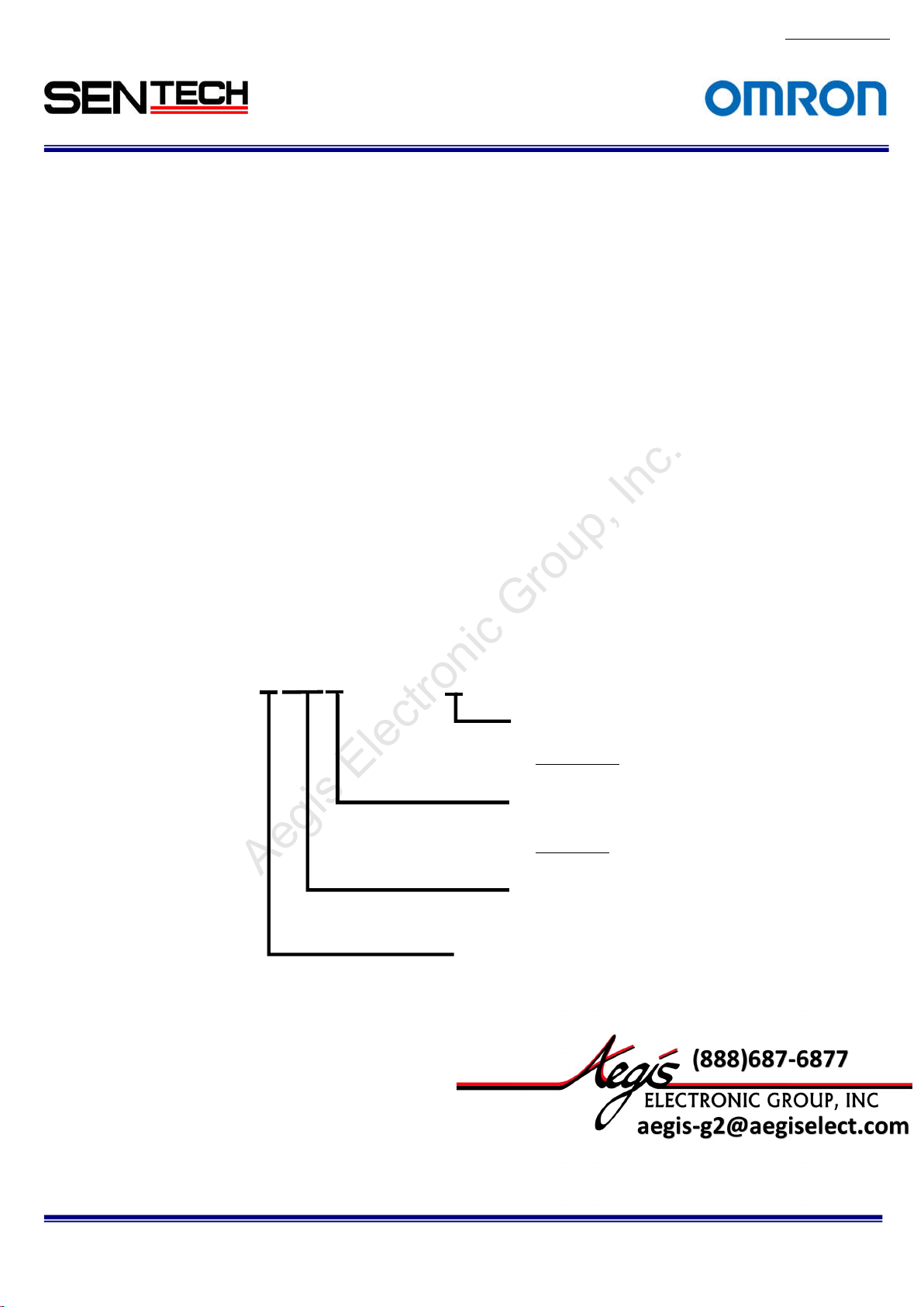
1.2. Naming
Specification
(Global Shutter)
No.13S0
80-10
STC-CMxxxxPCL-x
None: Standard
NIR: Near IR
Sensor Size
3: 1/3 inch
0: 2/3 i
nch
1:1 inch
Resolution
GA
3 : V
20: 2M Pixel
40: 4M Pixel
C: Color
B: Monochrome
STC-CMB200P
Specifications and Users guide
CL / STC-CMC200PCL / STC-CMB401PCL / STC-CMC401PCL
6
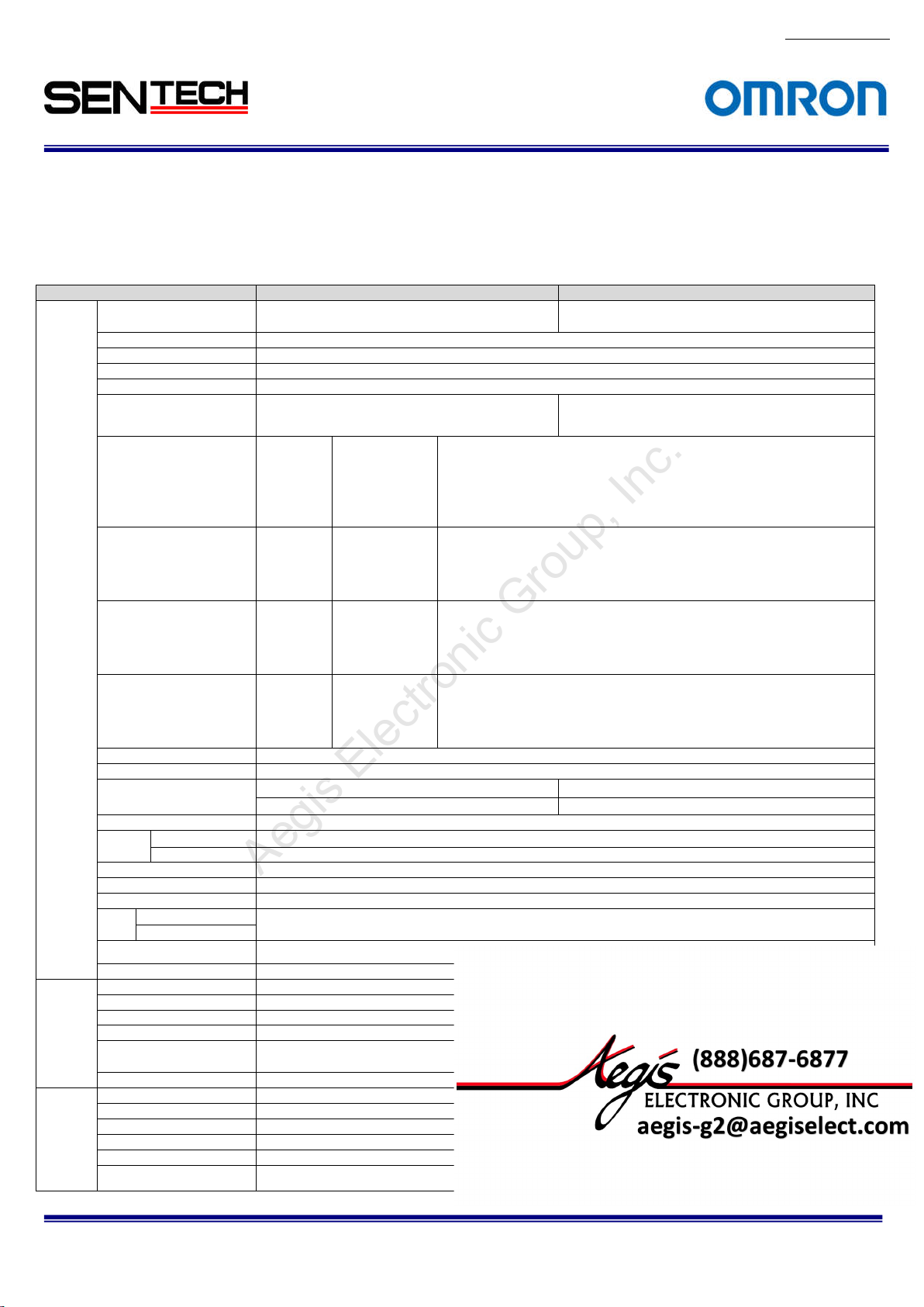
Product
STC-CMC200
PCL
STC-CMB200
PCL
Active picture ele
ments
2048 (H)
x
1088 (V)
Chip size
11.264×5.984 mm
Cell s
ize
5.5 (H) x 5.5
(V) µm
Scanning system
Progressive
Noise lev
el (8bit output)
Less than
3 Digit (Gain 0 dB)
Dynam
icrange
60 dB
Minimum sce
ne illumination
Sync. System
Internal
'@10bit ou
tput
MIDEUM /
BASE configuration
Shutter s
peed
45 se
conds to
21u se
conds (Variable at line)
, from 22 u second
s (Variable at
usec)
Digital gain
1x to 5x
Gamma
1.0
Consum
ption
Communica
tion
RS232 via Ca
mera Link connector
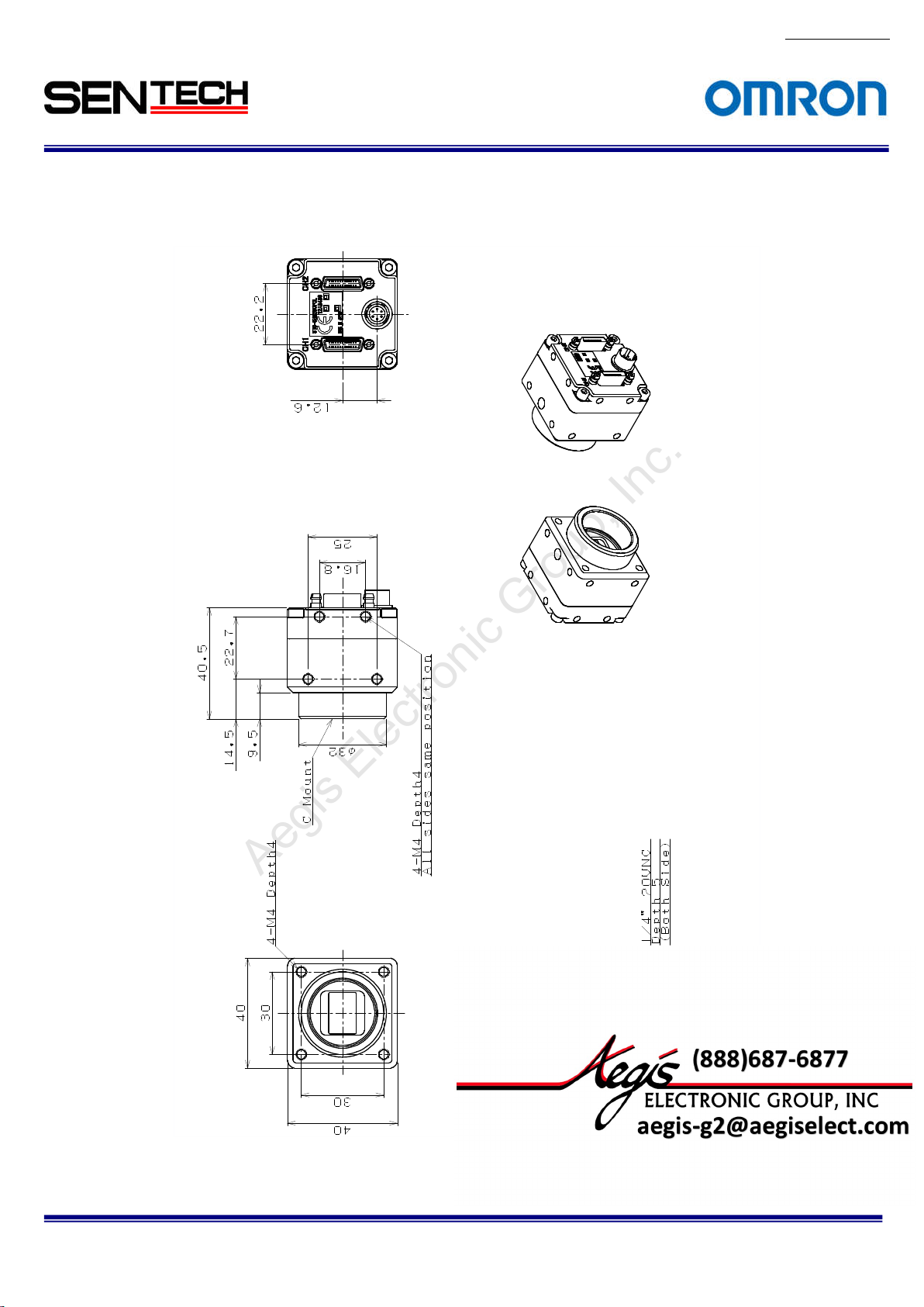
Dimensions
40 (W) x 40 (H) x 40.5 (D) mm (Excluding the connector)
Optical filter
No IR
cut filter
Material
Aluminu
m (AC)
Lens mount
C mount
Weight
Approxim
ately
90 g
Operati
onal temperature
-5 to 40 deg
. C
Storage temperature
-30 to 65 deg. C
Vibration
20Hz t
o 200Hz to 20Hz (5min./cycle), acceleration 10G, XYZ 3
directi
ons 30 min. each)
Shock
Acceleration
38G, half amplitude 6ms, XYZ 3 directions 3times each
Standa
rd compliancy
EMS: EN61000-6-2, EMI
: EN550
11 (Class A)
For more information please contact Aegis Electronic Group, Inc. *(888)687-6877 *aegis-g2@aegiselect.com *http://www.aegiselect.com
Aegis Electronic Group, Inc.
2. Specifications
2.1. Electronic spe
2.1.1. STC-
CMB200PCL
Color)
cifications / Mechanical specifications / Environmental specifications
(2Meg, Monoc
hrome) / STC-
CMB200PCL
-NIR (2Meg, Ne
ar IR) / STC-
No.13S0
CMC200PCL
80-10
(2Meg,
Electro
nic
spec
ations
Imager 2/3" Meg color progressive CMOS
ific
Scanning
Pixel frequ
sensor
Frame rate
Vertical frequency of
the Camera Link output
Horizon
the Camera Link output
Pixel fre
the Camera Link output
method Full scanning, Variable ROI Full scanning, Variable ROI
ency of the
tal frequency of
quency o
1X2-1Y
1X4-1Y
1X8-1Y
1X10⁻¹Y
1X2-1Y
1X4-1Y
1X8-1Y
1X10⁻¹Y
1X2
-1Y
1X4-1Y
1X8-1Y
1X10⁻¹Y
1X2-1Y
1X4-1Y
1X8-1Y
1X10⁻¹Y
(CMOSIS: CMV2000)
(8bit/10bit):
(8bit/10bit):
(8bit):
(8bit):
(8bit/10bit):
(8bit/10bit):
(8bit):
(8bit):
(8bit/10bit):
(8bit/10bit):
(8bit):
(8bit):
(8bit/10bit):
(8bit/10bit):
(8bit):
(8bit):
2/3" Meg monochrome progressive CMOS
Binning scanning,
10.625MHz (2,048 x 1,088), 21.250MHz (1,024 x 1,088),
42.500MHz ( 512 x 1,088)
21.250MHz (2,048 x 1,088), 42.500MHz (1,024 x 1,088)
42.500MHz (2,048 x 1,088)
48.000MHz (2,040 x 1,088)
73.8fps (2,048 x 1,088),147.6fps (1,024 x 1,088),295.1fps (512 x 1,088)
147.6fps (2,048 x 1,088), 295.1fps (1,024 x 1,088)
295.1fps (2,048 x 1,088)
333.3fps (2,040 x 1,088)
82kHz (2,048 x 1,088), 164kHz (1,024 x 1,088), 329kHz (512 x 1,088)
164kHz (2,048 x 1,088), 329kHz (1,024 x 1,088)
329kHz (2,048 x 1,088)
372kHz (2,040 x 1,088)
85MHz/42.5MHz
85MHz/42.5MHz
85MHz/42.5MHz
85MHz/42.5MHz
(CMOSIS: CMV2000)
Binning variable
ROI *1
F1.2 1 Lux at F1.2
- TBD Lux at F1
TAP / FULL / MIDEUM / BASE configuration
± 10% (PoCL or Power/IO connector)
Less than 3.0 W
Power/IO connector: HR10A-7R-6PB (Hirose) or equivalent
.2
Mechan
ical
specific
ations
Environ
men
tal
specific
ations
*Near
IR model (-NIR)
Video
ou
Po
wer
Operation mode Free-run, Edge preset trigger (V-reset), Pulse width trigger (V-reset)
Interface connector Camera Link connector: SDR connector x 2
RoHS RoHS compliance
'@8bit output 10
tput
Input voltage 12Vdc
2 Lux at
*1: Binning support on 8,10bit
STC-CMB200P
Specifications and Users guide
CL / STC-CMC200PCL / STC-CMB401PCL / STC-CMC401PCL
7

Product
STC- CMC401PCL
STC- CMB401PCL
Active picture elements
2048 (H)
x 2048 (V)
Chip size
11.264×1
1.264 mm
Cell size
5.5 (H) x 5.5 (V) µm
Scanning
system
Progres
sive
Noise lev
el (8bit output)
Less than
3 Digit (Gain 0 dB)
Dynamicrange
60 dB
Sync. Sy
stem
Internal
output
'@10bit ou
tput
MIDEUM /
BASE configuration
Shutter s
peed
45 se
conds to 25.8u seconds (Variable at line)
Digital gain
1x to 4x
Gamma
1.0
Less than 3.2 W
Consumption
Communica
tion
RS232 via Ca
mera Link
conne
ctor
Dimen
sions
40 (W) x 40 (H) x 40.5 (D) mm
(Excluding the connector
)
Optical filter
No IR cut filter
Material
Aluminu
m (AC)
Lens mount
C mount
Weight
Approxim
ately
90 g
Operational temperature
-5 to 40 deg. C
Storag
e temperature
-30 to 65 de
g. C
Vibration
20Hz t
o 200Hz to 20Hz (5min./cycle),
acceler
ation 10G, XYZ 3 directions 30 min. each)
Shock
Acceleration 38G, half amplitude 6ms, XYZ 3 directions 3times each
Standa
rd compliancy
EMS: EN61000-6-2, EMI
: EN550
11 (Class A)
For more information please contact Aegis Electronic Group, Inc. *(888)687-6877 *aegis-g2@aegiselect.com *http://www.aegiselect.com
Aegis Electronic Group, Inc.
2.1.2
No.13S0
80-10
STC-CMB401PCL (4Meg, Monochrome) / STC-CMB401PCL-NIR (4Meg,Near IR) /STC-CMC401PCL (4Meg,
Color)
Electron
ic
ific
spec
ations
Imager 1" 4Meg color progressive CMOS
(CMOSIS: CMV4000)
Scanning
Pixel frequ
sensor
Frame rate
Vertical frequency of
the Camera Link output
Horizon
the Camera Link output
Pixel frequency o
the Camera Link output
method Full scanning, Variable ROI Full scanning, Variable ROI
ency of the
tal frequency of
1X2-1Y
1X4-1Y
1X8-1Y
1X10⁻¹Y
1X2-1Y
1X4-1Y
1X8-1Y
1X10⁻¹Y
1X2
-1Y
1X4-1Y
1X8-1Y
1X10⁻¹Y
1X2-1Y
1X4-1Y
1X8-1Y
1X10⁻¹Y
(8bit/10bit):
(8bit/10bit):
(8bit):
(8bit):
(8bit/10bit):
(8bit/10bit):
(8bit):
(8bit):
(8bit/10bit):
(8bit/10bit):
(8bit):
(8bit):
(8bit/10bit):
(8bit/10bit):
(8bit):
(8bit):
10.625MHz (2,048 x 2,048), 21.250MHz (1,024 x 2,048),
42.500MHz ( 512 x 2,048)
21.250MHz (2,048 x 2,048), 42.500MHz (1,024 x 2,048)
42.500MHz (2,048 x 2,048)
48.000MHz (2,040 x 2,048)
39.7fps (2,048 x 2,048), 79.2fps (1,024 x 2,048), 158.6fps (512 x 2,048)
79.3fps (2,048 x 2,048), 158.6fps (1,024 x 2,048)
158.6fps (2,048 x 2,048)
179.2fps (2,040 x 2,048)
82kHz (2,048 x 2,048), 164kHz (2,024 x 1,048), 329kHz (512 x 2,048)
164kHz (2,048 x 2,048), 329kHz (1,024 x 2,048)
329kHz (2,048 x 2,048)
372kHz (2,040 x 2,048)
85MHz/42.5MHz
85MHz/42.5MHz
85MHz/42.5MHz
85MHz/42.5MHz
1" 4Meg monochrome progressive CMOS
(CMOSI
Binning scanning, Binning variable ROI*1
S: CMV4000)
m scene
Minimu
illumination *Near
Video
Power Input voltage 12Vdc
Operati
Mechan
ical
specific
ations
Environ
mental
specific
ations
Interface connector Camera Link connector: SDR connector x 2
RoHS Ro
STC-CMB200P
'@8bit output 10
on mode Free-run, Edge preset trigger (V-reset), Pulse width trigger (V-reset)
CL / STC-CMC200PCL / STC-CMB401PCL / STC-CMC401PCL
Specifications and Users guide
Less than 1 Lux at F1.2 Less than 1 Lux at F1.2
- TBD Lux at F1
TAP / FULL / MIDEUM / BASE configuration
± 10% (PoCL or Power/IO connector)
HS compliance
.2
8

*1: Binning
For more information please contact Aegis Electronic Group, Inc. *(888)687-6877 *aegis-g2@aegiselect.com *http://www.aegiselect.com
Aegis Electronic Group, Inc.
support on 8,10bit
No.13S0
80-10
STC-CMB200P
Specifications and Users guide
CL / STC-CMC200PCL / STC-CMB401PCL / STC-CMC401PCL
9
10
For more information please contact Aegis Electronic Group, Inc. *(888)687-6877 *aegis-g2@aegiselect.com *http://www.aegiselect.com
Aegis Electronic Group, Inc.
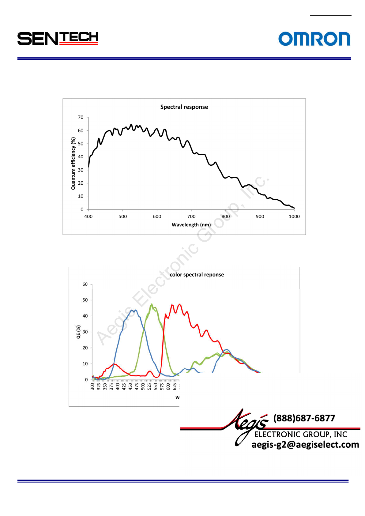
2.2 Spectral
2.2.1 STC-CMB200PCL / STC-CMB401PCL
Sensitivity Characteristics
No.13S0
80-10
2.2.2
STC-CMC200PCL / STC-CMC401PCL
STC-CMB200P
Specifications and Users guide
CL / STC-CMC200PCL / STC-CMB401PCL / STC-CMC401PCL
11
For more information please contact Aegis Electronic Group, Inc. *(888)687-6877 *aegis-g2@aegiselect.com *http://www.aegiselect.com
Aegis Electronic Group, Inc.
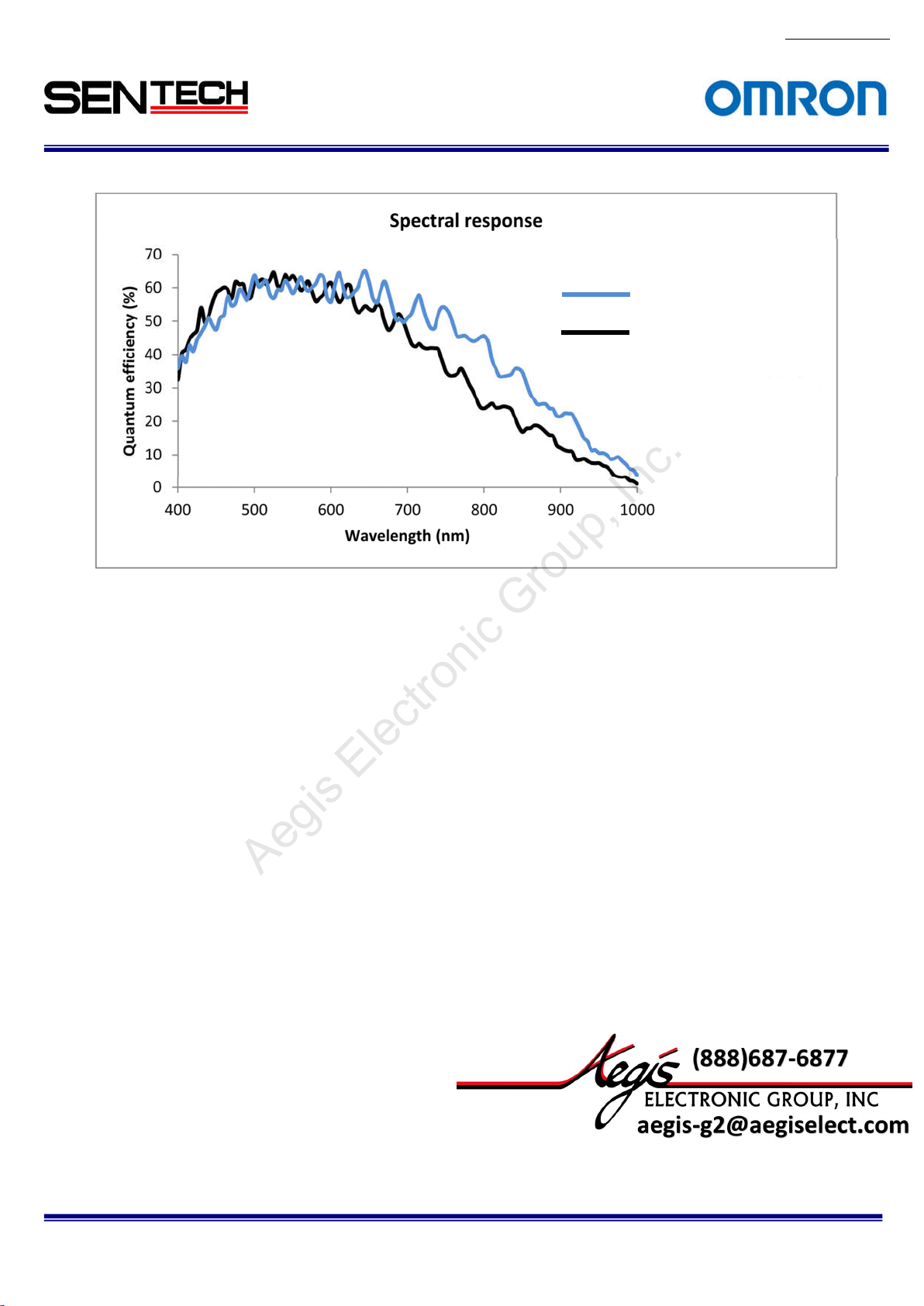
2.2.3
STC-CMB200PCL NIR / STC-CMB401PCL-NIR (Near IR model)
Near IR Model
Normal Model(Mono)
No.13S0
80-10
STC-CMB200P
Specifications and Users guide
CL / STC-CMC200PCL / STC-CMB401PCL / STC-CMC401PCL
No.13S0
12
For more information please contact Aegis Electronic Group, Inc. *(888)687-6877 *aegis-g2@aegiselect.com *http://www.aegiselect.com
Aegis Electronic Group, Inc.
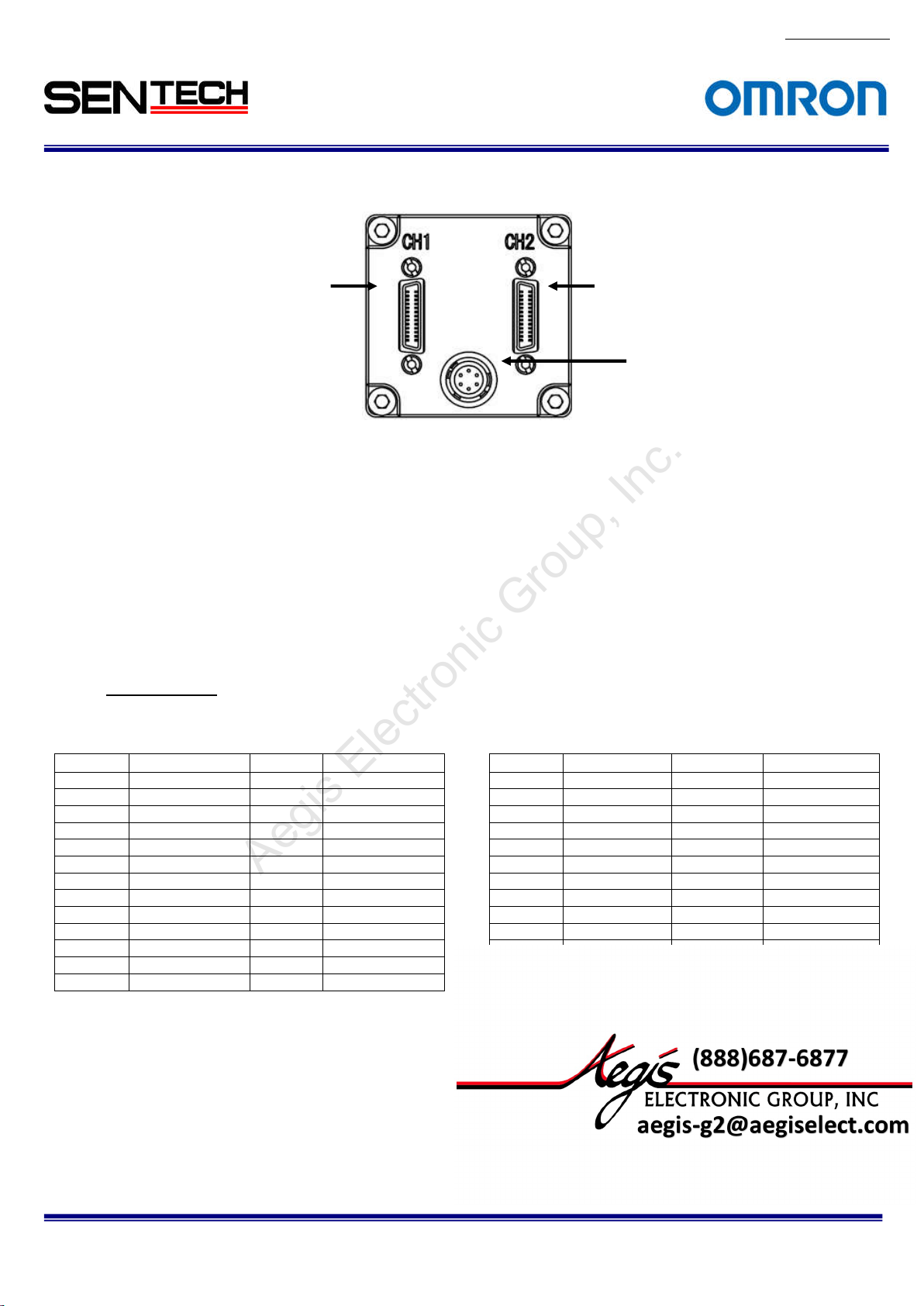
2.3 Connector
specifications
26-pin SDR c
(Base
Camera Link Connector)
onnector
26-pin SDR connector
(Medium / Full
Camera Link Connector)
Power/IO c
onnector
2.3.1 Camera Link connectors:
SDR (3M) equiva
lent x 2
(CAUT
ION)
This product is PoCL type.
When the frame grabber board and the cable are applicable for the PoCL, the frame grabber
board supplies the power to the camera. In this case, please DO NOT supply the power from
the Power/IO connector.
When the frame grabber board and the cable are NOT applicable for the PoCL, please input the
power from the Power/IO connector.
Pin assignment
Base Camer
a Link Connector Medium / Full Camera Link Connector
Pin No. Signal Name Pin No. Signal Name Pin No. Signal Name Pin No. Signal Name
1 +12V 14 GND 1 +12V 14 GND
2 X0- 15 X0+ 2 Y0- 15 Y0+
3 X1- 16 X1+ 3 Y1- 16 Y1+
4 X2- 17 X2+ 4 Y2- 17 Y2+
5 Xclk- 18 Xclk+ 5 Yclk- 18 Yclk+
6 X3- 19 X3+ 6 Y3- 19 Y3+
7 SerTC+ 20 SerTC- 7 100Ω 20 100Ω
8 SerTFG- 21 SerTFG+ 8 Z0- 21 Z0+
9 CC1- (TRG) 22 CC1+ (TRG) 9 Z1- 22 Z1+
10 CC2+ 23 CC2- 10 Z2- 23 Z2+
11 CC3- 24 CC3+ 11 Zclk- 24 Zclk+
12 CC4+ 25 CC4- 12 Z3- 25 Z3+
13 GND 26 +12V 13 GND 26 +12V
80-10
STC-CMB200P
CL / STC-CMC200PCL / STC-CMB401PCL / STC-CMC401PCL
Specifications and Users guide
13
For more information please contact Aegis Electronic Group, Inc. *(888)687-6877 *aegis-g2@aegiselect.com *http://www.aegiselect.com
Aegis Electronic Group, Inc.
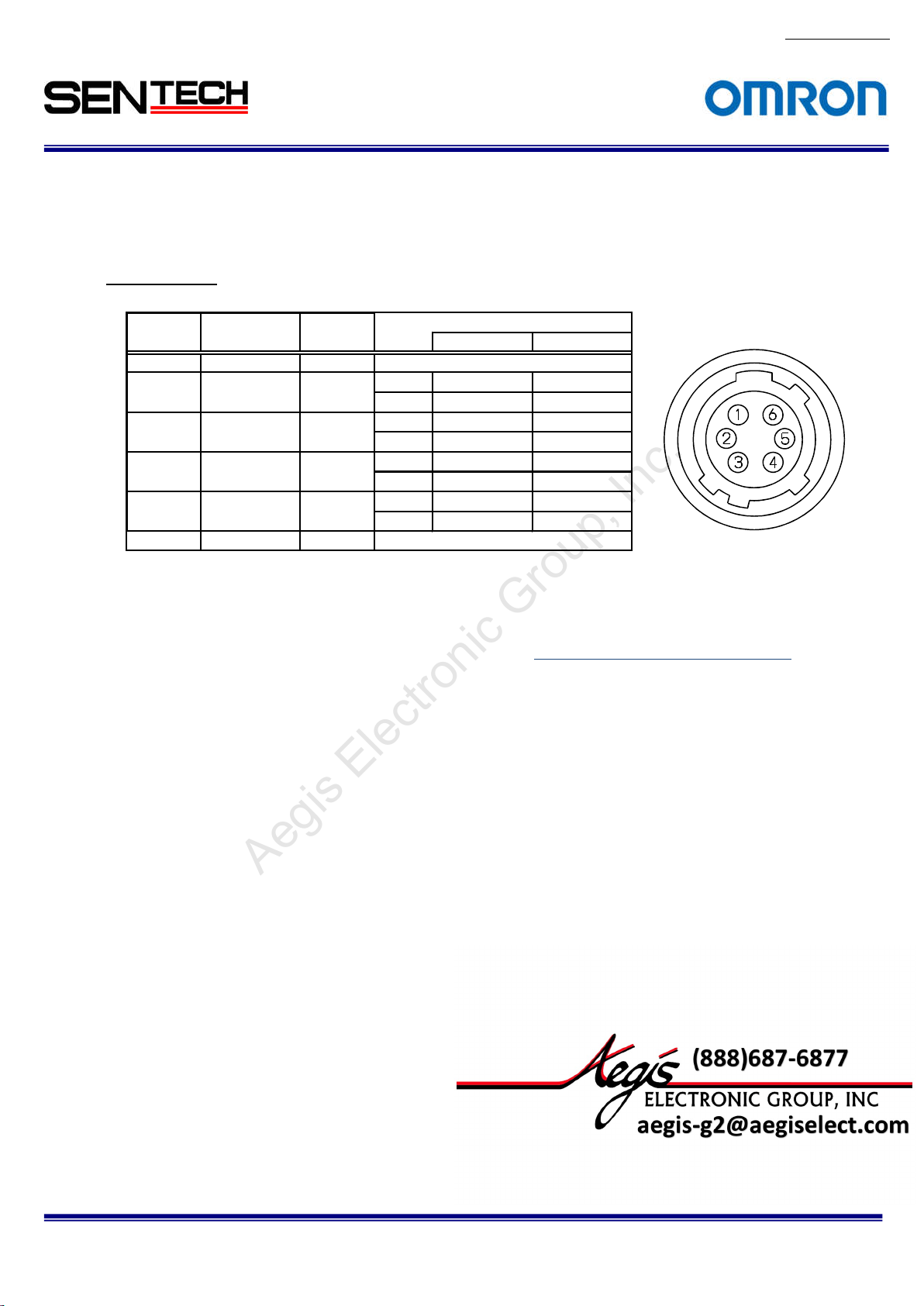
2.3.2
No.13S0
Power/IO connector: HR10A-7R-6PB (Hirose) or equivalent.
This connector is for 12Vdc power input and the input and output signals.
The trigger input and sync input /output signals can be assigned through the
camera setting communication.
Pin assignment
Pin No Signal Name IN/OUT Voltage
LowVolta
1 GND IN
2 SP-4 IN/OUT IN 0 ~ +0.99V +2.3 ~ +5.0V
OUT 0V +3.3V
3 SP-3 IN/OUT IN 0 ~ +0.99V +2.3 ~ +5.0V
OUT 0V +3.3V
4 SP-2 IN/OUT IN 0 ~ +0.99V +2.3 ~ +5.0V
OUT 0V +3.3V
5 SP-1 IN/OUT IN 0 ~ +0.99V +2.3 ~ +5.0V
OUT 0V +3.3V
6 +12Vdc IN
(Note 1)
rigger input signal can be assigned either on Camera Link connector (CC1) or on the No. 2 pin of the
T
power/IO connector through the camera setting communication.
As for the actual setting of hardware trigger, please refer to
ge
0V
+12Vdc
HighVoltage
0.エラー! 参照
元が見つかりません。
80-10
STC-CMB200P
Specifications and Users guide
CL / STC-CMC200PCL / STC-CMB401PCL / STC-CMC401PCL
14
For more information please contact Aegis Electronic Group, Inc. *(888)687-6877 *aegis-g2@aegiselect.com *http://www.aegiselect.com
Aegis Electronic Group, Inc.
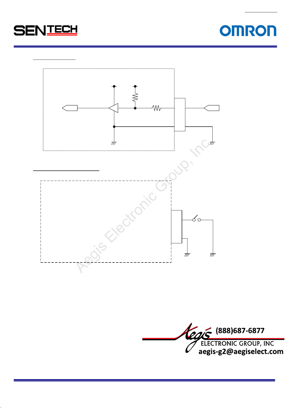
Input Signa
l Circuit
Cam
era
Camera
ut
inp
(to FPGA)
Input Signal Circuit Examples
Came
ra
input
(to FPGA)
TC7WH24
TC7WH241FK
+3.3V
Camera
1FK
+3.3V
+3.3V
+3.3V
47kΩ
47kΩ
100Ω
100Ω
6Pin Conecto
2,3,4,
5
1
6Pin Conector
Pin. 2 or 3 o
2,3,4,
5
1
r
2 or 3 or 4 or 5
Pin.
r 4 or 5
User INPUT
GND
No.13S0
80-10
STC-CMB200P
CL / STC-CMC200PCL / STC-CMB401PCL / STC-CMC401PCL
Specifications and Users guide
15
For more information please contact Aegis Electronic Group, Inc. *(888)687-6877 *aegis-g2@aegiselect.com *http://www.aegiselect.com
Aegis Electronic Group, Inc.
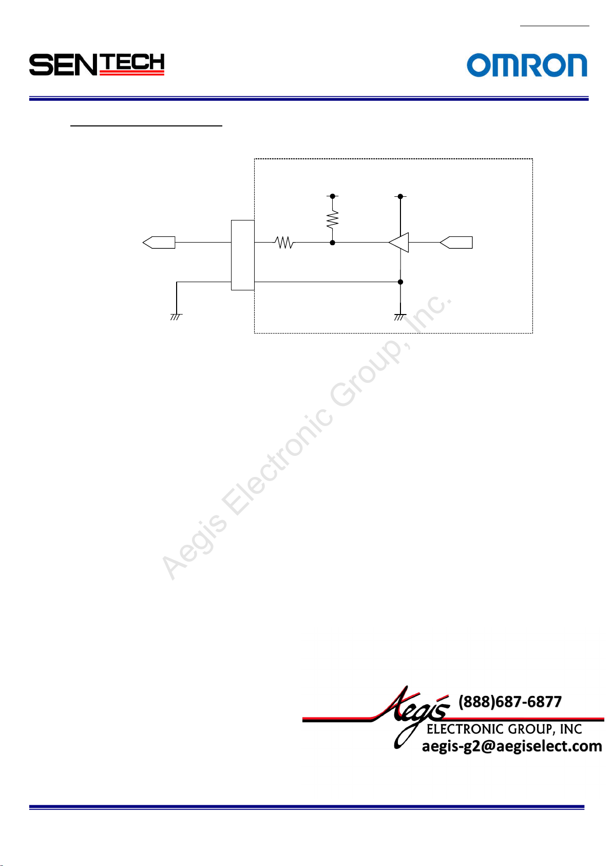
Output Signa
User Output
Voltage 0 to
+3.3V DC
l Circuit/ Examples
Pin. 2 or 3 or
GND
6 Pin Conector
4 or 5
2,3,4,
5
1
Came
100Ω
ra
+3.3V
47kΩ
+3.3V
TC7WH241FK
Camera
o
utput
(from FPGA)
No.13S0
80-10
STC-CMB200P
Specifications and Users guide
CL / STC-CMC200PCL / STC-CMB401PCL / STC-CMC401PCL
16
For more information please contact Aegis Electronic Group, Inc. *(888)687-6877 *aegis-g2@aegiselect.com *http://www.aegiselect.com
Aegis Electronic Group, Inc.
3. Dimensions
3.1. STC-CMB200P
CL / STC-CMB200PCL-NIR / STC-CMC200PCL
No.13S0
80-10
Unit: m
STC-CMB200P
Specifications and Users guide
CL / STC-CMC200PCL / STC-CMB401PCL / STC-CMC401PCL
m

17
For more information please contact Aegis Electronic Group, Inc. *(888)687-6877 *aegis-g2@aegiselect.com *http://www.aegiselect.com
Aegis Electronic Group, Inc.
3.2 STC-CMB401PCL /
STC-CMB401PCL-NIR / STC-CMC401PCL
No.13S0
80-10
Unit: m
STC-CMB200P
Specifications and Users guide
CL / STC-CMC200PCL / STC-CMB401PCL / STC-CMC401PCL
m

18
For more information please contact Aegis Electronic Group, Inc. *(888)687-6877 *aegis-g2@aegiselect.com *http://www.aegiselect.com
Aegis Electronic Group, Inc.
4. Camera Installation
For the i
Control software or Serial communication software to access the camera register.
As for using the software, please refer to the 0.
Control So
specifications.
Camera Link
When using on Full Configuration, please use the cable that has qualification.
Frame Graber should support Full, Medium, Base Configuration. When using the PoCL, Frame Graber
should support PoCL.
nstallation of this camera, these equipment as bellow are required.
ftware. As for accessing the register, please refer to the 7.The communication protocol
Cable x 2 (SDR Connector : Camera side)
No.13S0
80-10
STC-CMB200P
Specifications and Users guide
CL / STC-CMC200PCL / STC-CMB401PCL / STC-CMC401PCL
19
For more information please contact Aegis Electronic Group, Inc. *(888)687-6877 *aegis-g2@aegiselect.com *http://www.aegiselect.com
Aegis Electronic Group, Inc.
5. The camera output timing charts
5.1. The horizontal t
As for the vertical timing, please refer to 5.2.エラー! ブックマークが自己参照を行っています。. Highs Speed
Clock and Lo
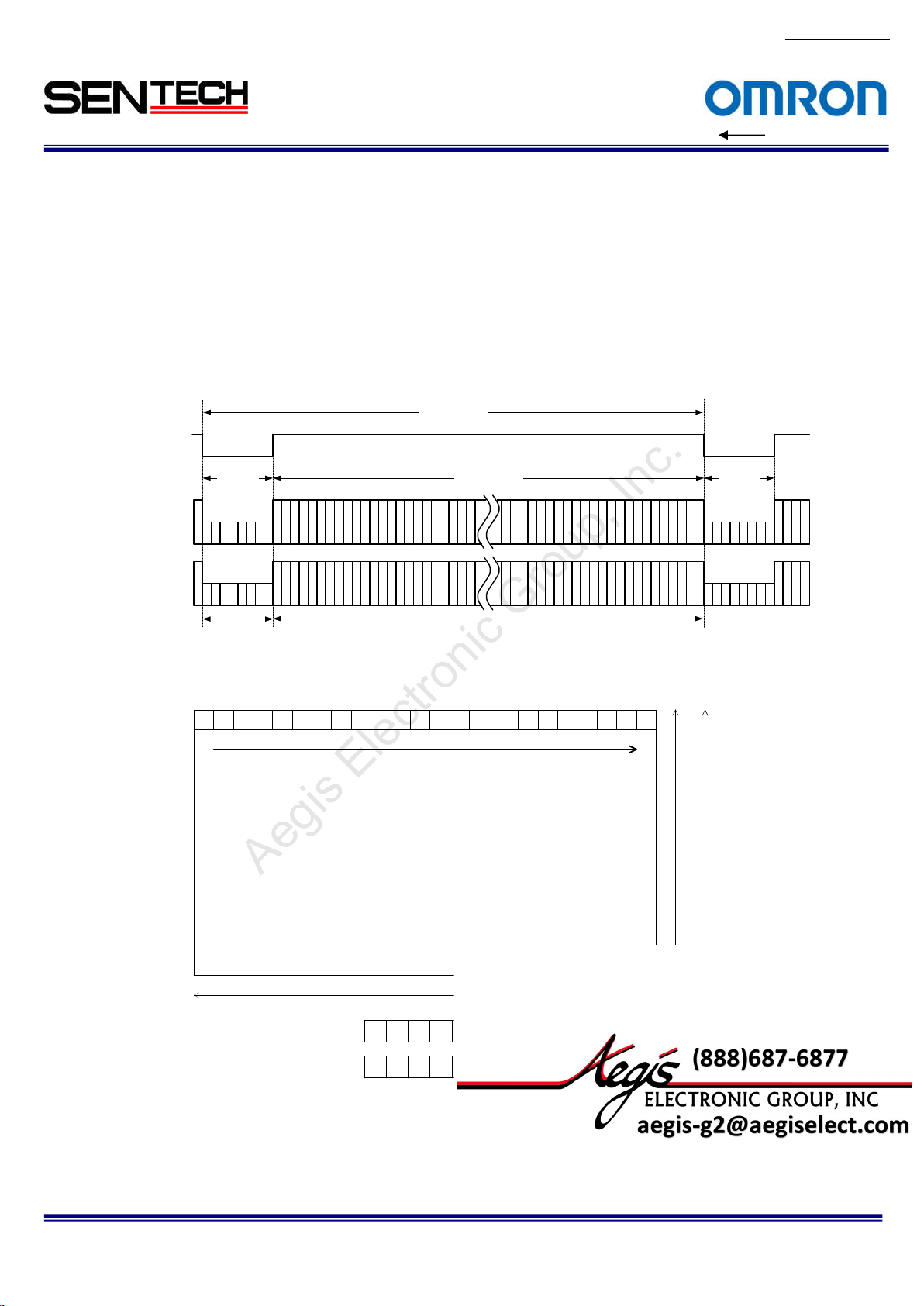
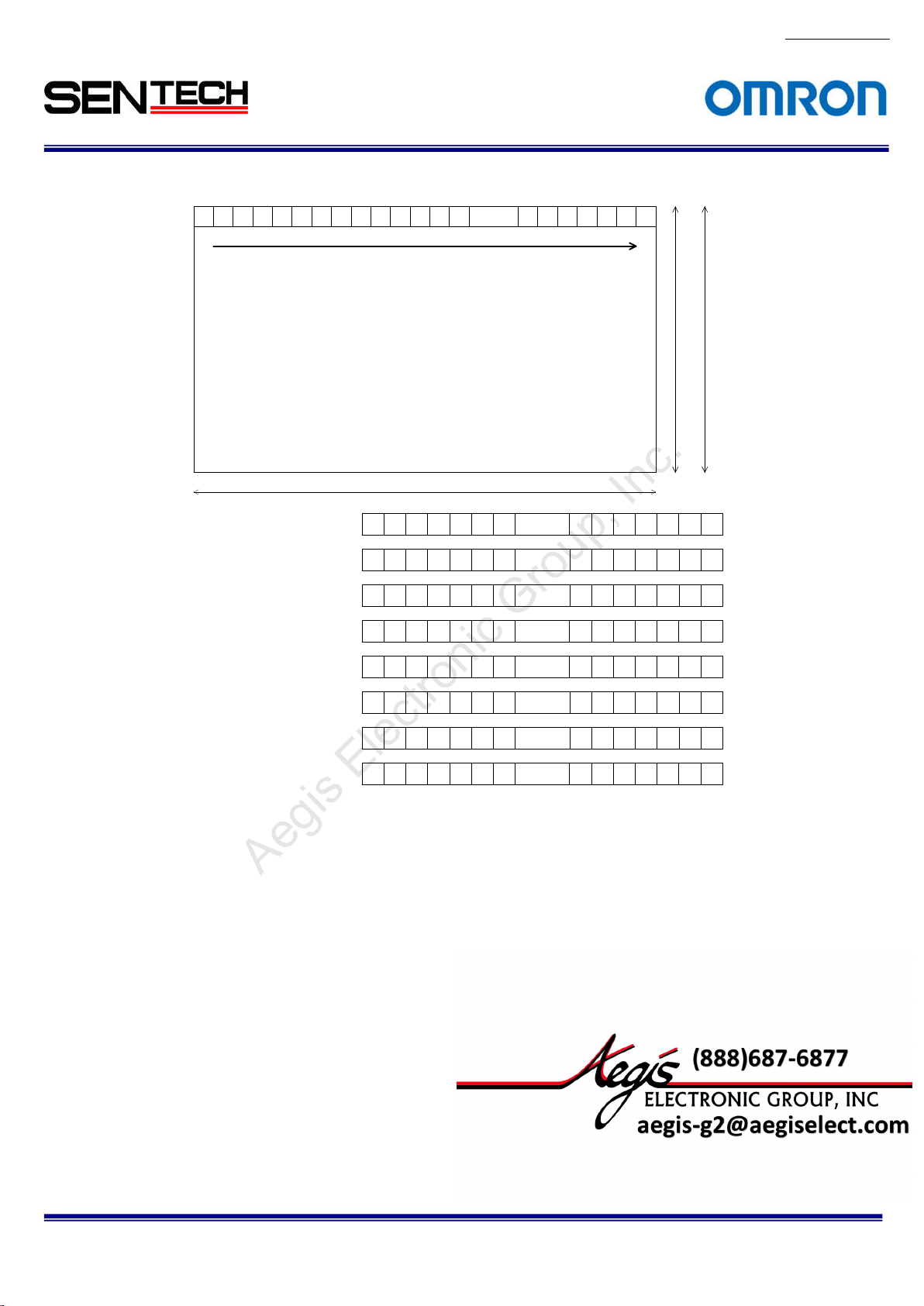
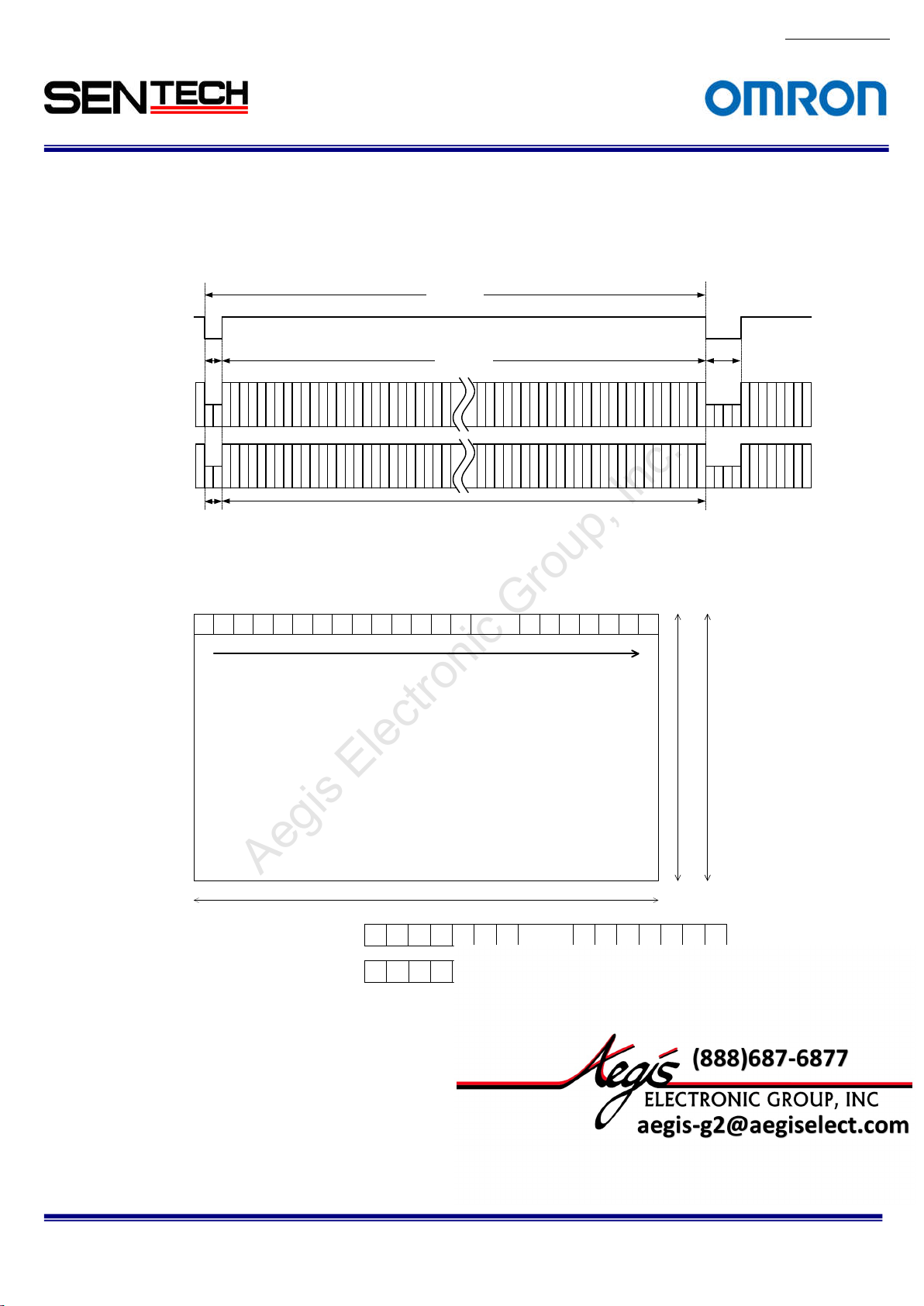
51.1 2 Taps (
1X2-1Y) / Horizontal 2,048 pixels
LVAL
Video out
ap 1: DA)
(T
Video out
ap 2: DB)
(T
The pixel order for the Image
TAP1: DA output pixels
TAP2: DB output pixels
imings (STC-CMB/CMC200PCL, CMB/CMC401PCL)
w Speed Clock are existed as Pixel Clock.
8 CLK
135
246
Horizontal
blanking
1 2
3 4 ...... 20425 6 7 8 9 10 11 12 13 14 20 43 2044 2045 2046 2047 2048
1 CLK =
11.764 nseconds(85MHz)
1 CLK = 23.524 nseconds(42.5MHz)
1,032
CLK
CLK
1,024
Video o
els
2,048 pix
1 3 5 7 ...... 20359 11 13 2037 2039 2041 20 43 2045 2047
2 4 6 8 ...... 20 3610 12 14 2038 2040 2042 2044 2046 2048
utput
One horizontal (1H)
2043
2044
2,048 lines
(STC-CMB4MCL/CMC4MCL)
47
20
2045
2046
2048
8 CLK
1,088 lines
(STC-CMB2MCL/CMC2MCL)
No.13S0
LED
80-10
STC-CMB200P
CL / STC-CMC200PCL / STC-CMB401PCL / STC-CMC401PCL
Specifications and Users guide
20
For more information please contact Aegis Electronic Group, Inc. *(888)687-6877 *aegis-g2@aegiselect.com *http://www.aegiselect.com
Aegis Electronic Group, Inc.
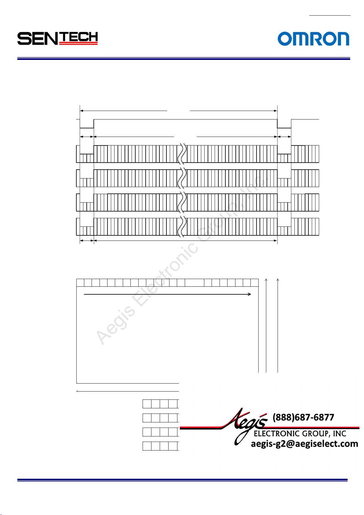
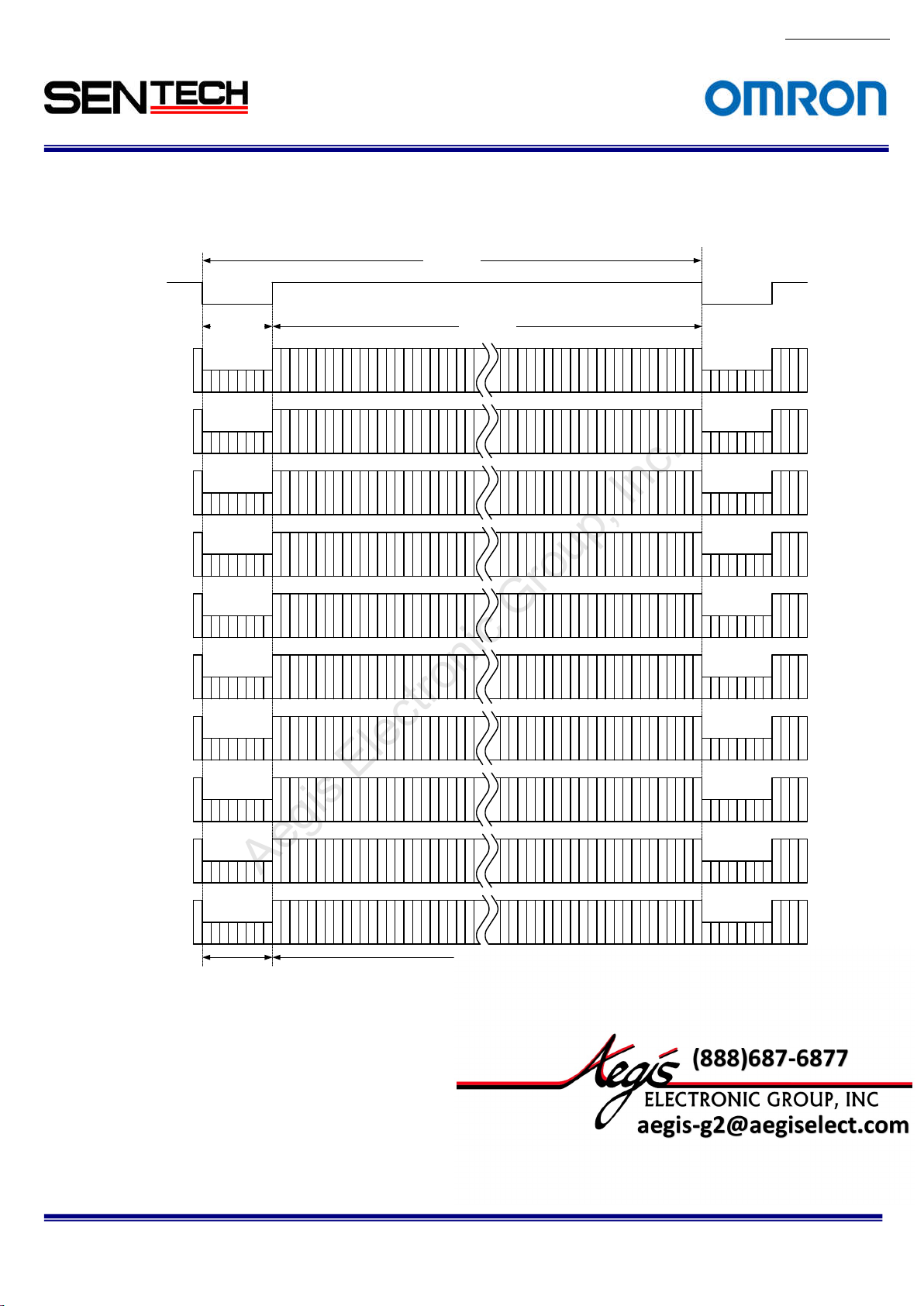
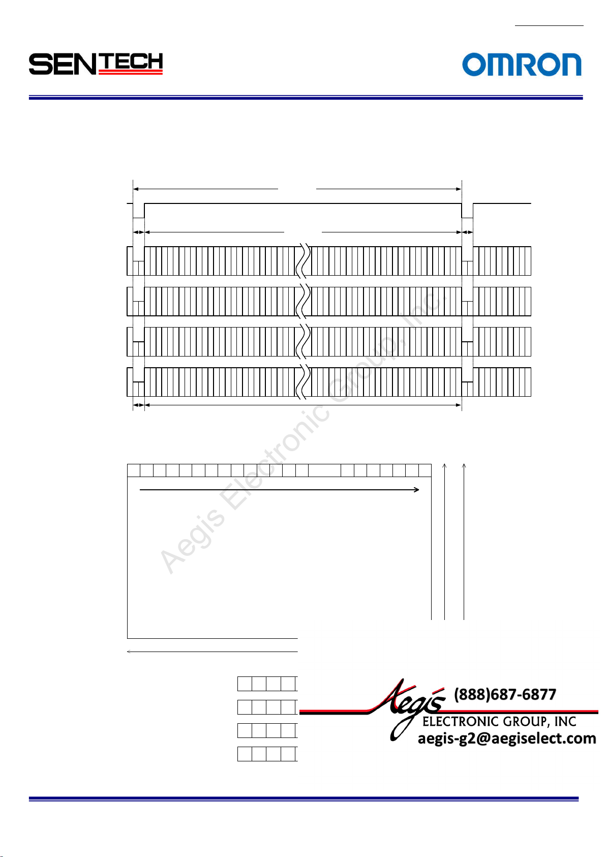
5.1.2
4Taps (1X4-1Y) / Horizontal 2,048 pixels
LVAL
4 CLK
Video out
ap1: DA)
(T
159
Video out
(Tap2: DB)
2
6
Video out
(Tap3: DC)
3
7
Video out
(Tap4: DD)
4
8
Horizontal
bl
anking
The pixel order for the Image
1 2
3 4 ...... 20425 6 7 8 9 10 11 12 13 14 20 43 2044 2045 2046 2047 2048
TAP1: DA output pixels
TAP2: DB output pixels
TAP3: DC output pixels
TAP4: DD output pixels
No.13S0
80-10
1 CLK = 11.764 nseconds(85MHz)
1 CLK = 23.524 nseconds(42.5MHz)
516 CLK
One
horizontal (1H)
512 CLK
4 CLK
2037
2041
2045
10
11
12
Video o
2,048 pix
1 5 9 13 ...... 20 2117 21 25 2025 2029 2033 2037 2041 2045
2 6 10 14 ...... 202218 22 26 2026 2030 2034 2038 2042 2046
3 7 11 15 ......202319 23 27 2027 2031 2035 2039 2043 2047
4 8 12 16 ......202420 24 28 2028 2032 2036 2040 2044 2048
utput
els
46
2038
2042
20
2039
2043
2047
2040
2044
2048
2,048 line
1,088 line
s (STC-CMB4MCL/CMC4MCL)
s (STC-CMB2MCL/CMC2MCL)
STC-CMB200P
CL / STC-CMC200PCL / STC-CMB401PCL / STC-CMC401PCL
Specifications and Users guide
21
For more information please contact Aegis Electronic Group, Inc. *(888)687-6877 *aegis-g2@aegiselect.com *http://www.aegiselect.com
Aegis Electronic Group, Inc.
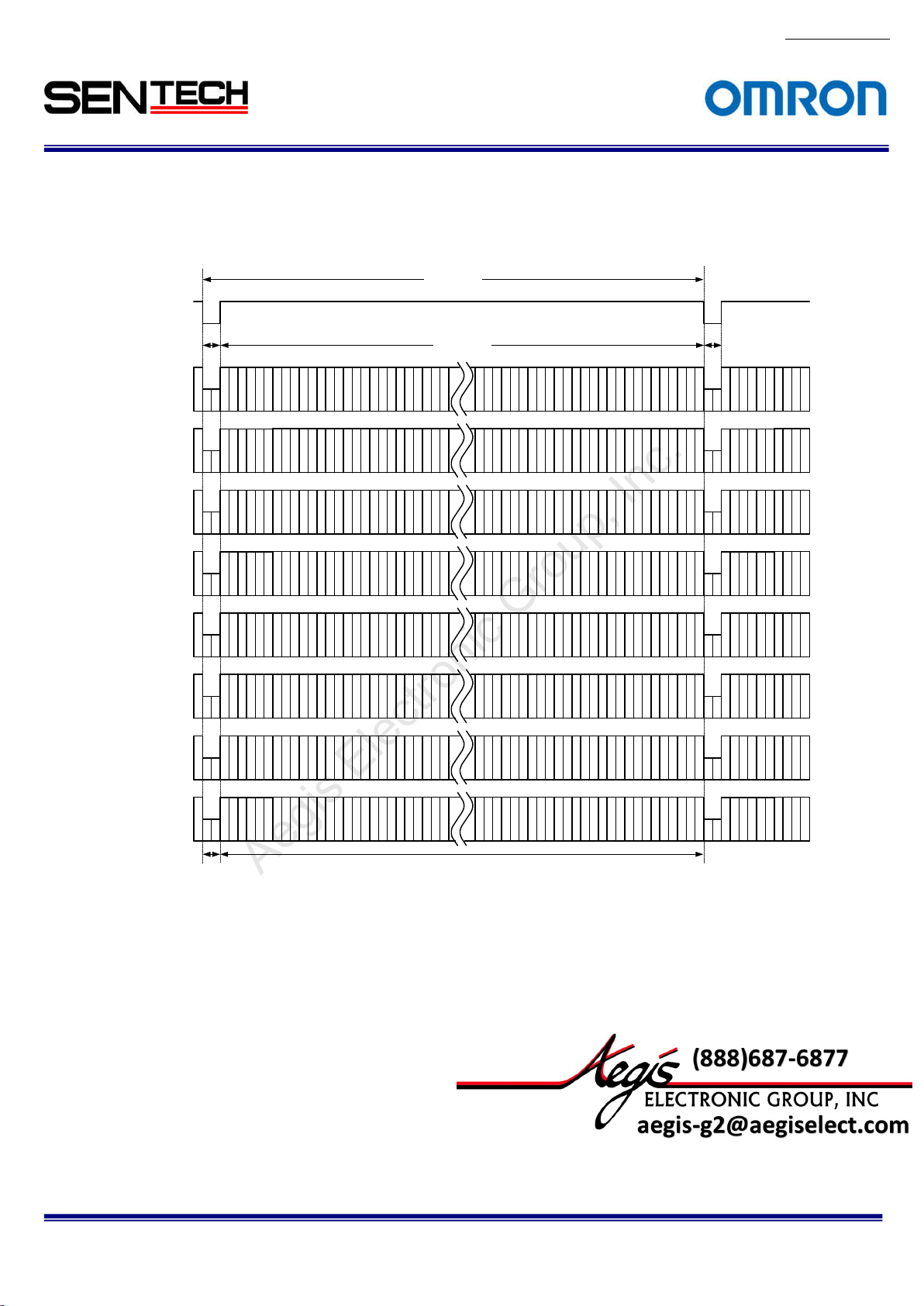
5.1.3
8 Taps (1X8-1Y) / Horizontal 2,048 pixels
LVA
L
2 CLK 2 CLK
Video out
(Tap1:DA)
1
9
17
Video out
(Tap2:DB)
2
10
18
258 CLK
256 CLK
No.13S0
1 CLK = 11.764 nseconds(85MHz)
1 CLK = 23.524 nseconds(42.5MHz)
One
horizontal (1H)
2025
2033
2041
2026
2034
2042
80-10
Video out
(Tap3:DC)
Vi
deo out
(Tap4:DD)
Video out
(Tap5:DE)
Video out
(Tap6:DF)
Video out
(Tap7:DG)
Video out
(Tap8:DH)
3
4
5
6
7
8
Horizontal
blanking
11
19
12
20
13
21
14
22
15
23
16
24
Video o
utput
2027
2035
2043
2028
2036
2044
2029
2037
2045
2030
2038
2046
47
2031
2039
20
2032
2040
2048
STC-CMB200P
CL / STC-CMC200PCL / STC-CMB401PCL / STC-CMC401PCL
Specifications and Users guide
22
For more information please contact Aegis Electronic Group, Inc. *(888)687-6877 *aegis-g2@aegiselect.com *http://www.aegiselect.com
Aegis Electronic Group, Inc.
The pixel or
der for the Image
1 2
3 4 ...... 20425 6 7 8 9 10 11 12 13 14 2043 2044 2045 2046 20 47 2048
TAP1: DA output pixels
TAP2: DB output pixels
TAP3: DC output pixels
TAP4: DD output pixels
TAP5: DE output pixels
TAP6: DF output pixels
TAP7: DG output pixels
TAP8: DH output pixels
2,048 line
s (STC-CMB4MCL/CMC4MCL)
2,048 pix
els
1 9 17 25 ......199333 41 49 2001 2009 2017 2025 2033 2041
2 10 18 26 ...... 199434 42 50 2002 2010 2018 2026 2034 2042
3 11 19 27 ......199535 43 51 2003 2011 2019 2027 2035 2043
4 12 20 28 ......199636 44 52 2004 2012 2020 2028 2036 2044
5 13 21 29 ......199737 45 53 2005 2013 2021 2029 2037 2045
6 14 22 30 ...... 199838 46 54 2006 2014 2022 2030 2038 2046
7 15 23 31 ......199939 47 55 2007 2015 2023 2031 2039 2047
8 16 24 32 ......200040 48 56 2008 2016 2024 2032 2040 2048
No.13S0
80-10
1,088 line
s (STC-CMB2MCL/CMC2MCL)
STC-CMB200P
CL / STC-CMC200PCL / STC-CMB401PCL / STC-CMC401PCL
Specifications and Users guide
23
For more information please contact Aegis Electronic Group, Inc. *(888)687-6877 *aegis-g2@aegiselect.com *http://www.aegiselect.com
Aegis Electronic Group, Inc.
5.1.4
10 Taps (1X10⁻¹Y) / Horizontal 2,040 pixels
LVAL
Video out
(T
ap1:DA)
24 to 2
CLK
5
Video out
(T
ap2:DB)
No.13S0
80-10
1 CLK = 12.500 nseconds (80MHz)
1 CLK = 25.000 nseconds(40MHz)
215 CLK
One horizontal (1H)
204 CLK
5
15
25
6
16
26
2015
2025
2035
36
2016
2026
20
Video out
(Tap3:DC)
Video out
(Tap4:DD)
Video out
(Tap5:DE)
Video out
(Tap6:DF)
Video out
(Tap7:DG)
Video out
(Tap8:DH)
Video out
(Tap9:DI)
Video out
(Tap10:DJ)
7
17
8
18
9
19
102030
112131
122232
132333
142434
27
28
29
2017
2027
2037
2018
2028
2038
2019
2029
2039
2020
2030
2040
2021
2031
2041
2022
2032
2042
2023
2033
2043
2024
2034
2044
Horizont
al
Video output
blanking
STC-CMB200P
CL / STC-CMC200PCL / STC-CMB401PCL / STC-CMC401PCL
Specifications and Users guide
24
For more information please contact Aegis Electronic Group, Inc. *(888)687-6877 *aegis-g2@aegiselect.com *http://www.aegiselect.com
Aegis Electronic Group, Inc.
The pixel or
der for the Image
TAP1: DA output pixels
TAP2: DB output pixels
TAP3: DC output pixels
TAP4: DD output pixels
TAP5: DE output pixels
TAP6: DF output pixels
TAP7: DG output pixels
TAP8: DH output pixels
TAP9: DG output pixels
TAP10: DH output pixels
15 16
17 18 ...... 20385 6 7 8 9 10 11 12 13 14 2039 2040 2041 20 42 2043 2044
2,048 lines (STC-CMB4MCL/CMC4MCL)
1,088 line
s (STC-CMB2MCL/CMC2MCL)
2,040 pixels
5 15 25 35 ......197545 55 65 1985 1995 2005 2015 2025 2035
6 16 26 36 ...... 197646 56 66 1986 1996 2006 2016 2026 2036
7 17 27 37 ......197747 57 67 1987 1997 2007 2017 2027 2037
8 18 28 38 ......197848 58 68 1988 1998 2008 2018 2028 2038
9 19 29 39 ......197949 59 69 1989 1999 2009 2019 2029 2039
10 20 30 40 ...... 198050 60 70 1990 2000 2010 2020 20 30 2040
11 21 31 41 ......198151 61 71 1991 2001 2011 2021 2031 2041
12 22 32 42 ......198252 62 72 1992 2002 2012 2022 2032 2042
13 23 33 43 ......198353 63 73 1993 2003 2013 2023 2033 2043
14 24 34 44 ...... 198454 64 74 1994 2004 2014 2024 2034 2044
No.13S0
80-10
STC-CMB200P
CL / STC-CMC200PCL / STC-CMB401PCL / STC-CMC401PCL
Specifications and Users guide
25
For more information please contact Aegis Electronic Group, Inc. *(888)687-6877 *aegis-g2@aegiselect.com *http://www.aegiselect.com
Aegis Electronic Group, Inc.
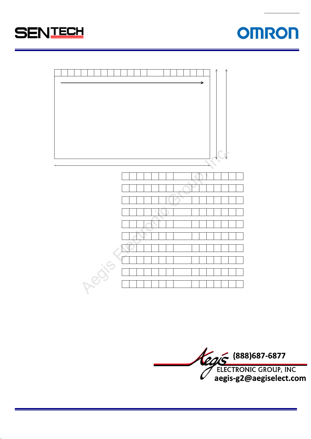
5.1.5
2Taps (1X2-1Y) / Horizontal 1,024 pixels
LVAL
4 CLK 4 CLK
Video out
ap 1: DA)
(T
135
Video out
(Tap 2: DB)
246
Horizontal
anking
bl
The pixel order for the Image
1 2
3 4 ...... 10185 6 7 8 9 10 11 12 13 14 1019 1020 1021 1022 1023 10 24
TAP1: DA output pixels
TAP2: DB output pixels
1 CLK = 11.764 nseconds(85MHz)
1 CLK = 23.524 nseconds(42.5MHz)
516 CLK
512 CLK
Video o
1,024
pixels
1 3 5 7 ...... 10119 11 13 1013 1015 1017 1019 1021 1023
2 4 6 8 ...... 101210 12 14 1014 1016 1018 1020 1022 1024
utput
horizontal (1H)
One
1023
1019
1021
1020
1022
1024
2,048 l
ines (STC-CMB4MCL/CMC4MCL)
No.13S0
80-10
1,088 l
ines (STC-CMB2MCL/CMC2MCL)
STC-CMB200P
CL / STC-CMC200PCL / STC-CMB401PCL / STC-CMC401PCL
Specifications and Users guide
26
For more information please contact Aegis Electronic Group, Inc. *(888)687-6877 *aegis-g2@aegiselect.com *http://www.aegiselect.com
Aegis Electronic Group, Inc.
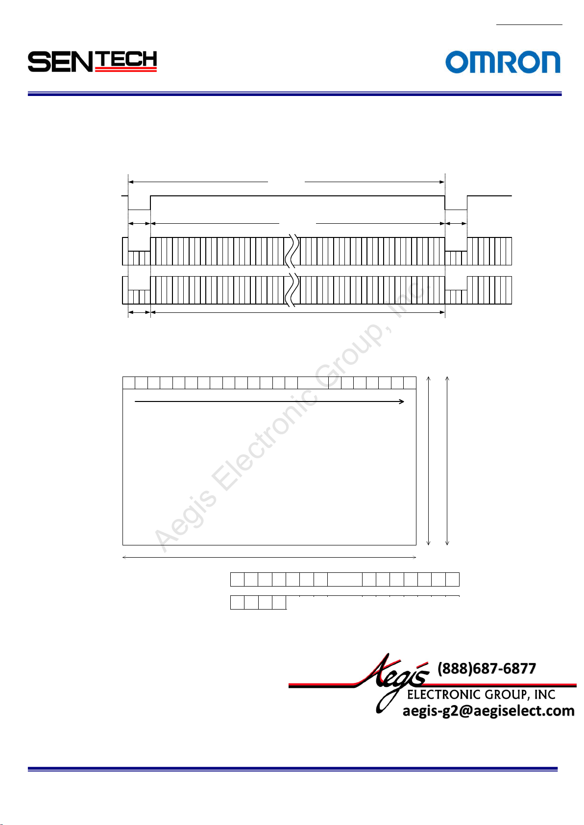
5.1.6
2Taps (1X2-1Y) / Horizontal 512 pixels
LVAL
2 CLK 2 CLK
Video out
(T
ap 1: DA)
135
Video out
(T
ap 2: DB)
246
Horizontal
bl
anking
The pixel order for the Image
1 2
3 4 ...... 5065 6 7 8 9 10 11 12 13 14 507 508 509 510 511 512
TAP1: DA output pixels
TAP2: DB output pixels
1 CLK = 11.764 nseconds(85MHz)
1 CLK = 23.524 nseconds(42.5MHz)
258 CLK
256 CLK
Video output
512 pixels
1 3 5 7 ...... 4999 11 13 501 50 3 505 507 509 511
2 4 6 8 ...... 50010 12 14 502 504 506 508 510 512
One
horizontal (1H)
1
51
507
509
508
510
512
2,048 l
ines (STC-CMB4MCL/CMC4MCL)
No.13S0
80-10
1,088 l
ines (STC-CMB2MCL/CMC2MCL)
STC-CMB200P
CL / STC-CMC200PCL / STC-CMB401PCL / STC-CMC401PCL
Specifications and Users guide
27
For more information please contact Aegis Electronic Group, Inc. *(888)687-6877 *aegis-g2@aegiselect.com *http://www.aegiselect.com
Aegis Electronic Group, Inc.
5.1.7
4Taps / Horizontal 1,024 pixels
LVAL
2 CLK
Video out
(T
ap1: DA)
159
Video out
(Tap2: DB)
2
6
10
Video out
(Tap3: DC)
3
7
11
Video out
(Tap4: DD)
4
8
12
Horizontal
anking
bl
The pixel order for the Image
1 2
3 4 ...... 10185 6 7 8 9 10 11 12 13 14 1019 1020 1021 1022 1023 10 24
TAP1: DA output pixels
TAP2: DB output pixels
TAP3: DC output pixels
TAP4: DD output pixels
1 CLK = 11.764 nseconds(85MHz)
1 CLK = 23.524 nseconds(42.5MHz)
258 CLK
256 CLK
Video o
1,024
1 5 9 13 ...... 99717 21 25 1001 1005 1009 1013 1017 1021
2 6 10 14 ...... 99818 22 26 1002 1006 1010 1014 1018 1022
3 7 11 15 ...... 99919 23 27 1003 1007 1011 1015 1019 1023
4 8 12 16 ...... 100020 24 28 1004 1008 1012 1016 10 20 1024
utput
pixels
horizontal (1H)
One
1013
1017
1021
22
1014
1018
10
1015
1019
1023
1016
1020
1024
2,048 l
ines (STC-CMB4MCL/CMC4MCL)
No.13S0
80-10
2 CLK
1,088 l
ines (STC-CMB2MCL/CMC2MCL)
STC-CMB200P
CL / STC-CMC200PCL / STC-CMB401PCL / STC-CMC401PCL
Specifications and Users guide
 Loading...