

Omron STC-CMB120APCL, STC-CMC120APCL, STC-CMB120APCL-F, STC-CMC120APCL-F Product Specifications And User's Manual
Page 1

1
STC-CMC120APCL, STC-CMB120APCL
Specifications and Users guide
For more information please contact Aegis Electronic Group, Inc. *(888)687-6877 *aegis-g2@aegiselect.com *http://www.aegiselect.com
Aegis Electronic Group, Inc.
12 Meg CMOS Color / Monochrome
Camera Link Camera
STC-CMC120APCL (12M Color)
STC-CMB120APCL (12M Monochrome)
Product Specifications and Users guide
No.14S056-11
Page 2

No.14S056-11
2
STC-CMC120APCL, STC-CMB120APCL
Specifications and Users guide
For more information please contact Aegis Electronic Group, Inc. *(888)687-6877 *aegis-g2@aegiselect.com *http://www.aegiselect.com
Aegis Electronic Group, Inc.
Table of Contents
1 OVERVIEW .................................................................................................................................................................... 5
1.1 FEATURES ....................................................................................................................................................................... 5
1.2 NAMING METHOD ........................................................................................................................................................... 5
2 SPECIFICATIONS ......................................................................................................................................................... 6
2.1 ELECTRONIC SPECIFICATIONS / MECHANICAL SPECIFICATIONS / ENVIRONMENTAL SPECIFICATIONS ............................ 6
2.1.1 STC- CMC120APCL (Color) / STC- CMB120APCL (Monochrome) .................................................................... 6
2.2 SPECTRAL SENSITIVITY CHARACTERISTICS .................................................................................................................... 7
2.2.1 STC-CMC120APCL/ STC-CMB120APCL ............................................................................................................ 7
2.3 CONNECTOR SPECIFICATIONS ......................................................................................................................................... 8
2.3.1 Camera Link connectors:....................................................................................................................................... 8
2.4 POWER/IO CONNECTOR: ................................................................................................................................................. 9
2.5 DIMENSIONS ................................................................................................................................................................. 12
3 CAMERA INSTALLATION .......................................................................................................................................... 14
4 THE CAMERA OUTPUT TIMING CHARTS .............................................................................................................. 15
4.1 THE HORIZONTAL TIMINGS (CMC120APCL) ................................................................................................................ 15
4.1.1 10 Taps (1X10⁻¹Y) / Horizontal:4,090 pixels ................................................................................................... 15
4.1.2 8 Taps (1X8-1Y) / Horizontal 4,096 pixels .......................................................................................................... 17
4.1.3 4 Taps (1X4-1Y) / Horizontal:4,096 pixels ....................................................................................................... 19
4.1.4 3 Taps (1X3-1Y) / Horizontal 4,092 pixels .......................................................................................................... 20
4.1.5 2 Taps (1X2-1Y) / Horizontal:4,096 pixels ....................................................................................................... 20
4.2 THE VERTICAL TIMINGS ................................................................................................................................................ 21
4.3 FULL SCAN (TC-CMC120APCL / STC-CMB120APCL).............................................................................................. 21
4.4 AOI OUTPUT TIMING .................................................................................................................................................... 22
4.5 CAMERA LINK BIT ASSIGNMENT .................................................................................................................................... 25
4.6 CAMERA LINK TAP GEOMETRY .................................................................................................................................... 29
4.6.1 10TAP (1X10⁻¹Y).................................................................................................................................................. 29
4.6.2 8TAP (1X8-1Y) ...................................................................................................................................................... 29
4.6.3 4TAP (1X4-1Y) ...................................................................................................................................................... 30
4.6.4 2TAP (1X2-1Y) ...................................................................................................................................................... 30
4.7 BAYER PATTERN FOR COLOR MODEL (ONLY STC-CMC120APCL) ............................................................................... 31
5 CAMERA FUNCTION MODES ................................................................................................................................... 32
5.1 NORMAL MODE .............................................................................................................................................................. 32
5.1.1 Normal mode (Electronic shutter) ...................................................................................................................... 32
5.2 PULSE WIDTH TRIGGER MODE ....................................................................................................................................... 33
5.2.1 Pulse width trigger mode .................................................................................................................................... 33
5.2.2 Pulse Width Trigger mode (Exposure timing).................................................................................................... 33
5.3 EDGE PRESET TRIGGER MODE ...................................................................................................................................... 34
5.3.1 Edge Preset Trigger mode ................................................................................................................................... 34
5.3.2 ..................................................................................................................................................................................... 34
5.3.3 Edge Preset Trigger mode (Exposure timing) .................................................................................................... 34
6 THE COMMUNICATION PROTOCOL SPECIFICATIONS ....................................................................................... 35
6.1 THE COMMUNICATION METHOD .................................................................................................................................... 35
6.2 THE COMMUNICATION SETTINGS .................................................................................................................................. 35
6.3 THE COMMUNICATION FORMAT ..................................................................................................................................... 36
6.4 THE CAMERA CONTROL COMMANDS .............................................................................................................................. 37
6.4.1 The camera commands list(Device Code:00H) ................................................................................................... 37
6.4.2 Description of the camera control commands (The under line settings are the factory default settings) ..... 40
6.4.3 Camera Control Command list (Device Code:3AH)........................................................................................... 49
Page 3

No.14S056-11
3
STC-CMC120APCL, STC-CMB120APCL
Specifications and Users guide
For more information please contact Aegis Electronic Group, Inc. *(888)687-6877 *aegis-g2@aegiselect.com *http://www.aegiselect.com
Aegis Electronic Group, Inc.
8 CONTROL SOFTWARE ............................................................................................................................................... 54
8.1 SUMMARY ...................................................................................................................................................................... 54
8.1.1 File ........................................................................................................................................................................ 55
8.1.2 Comm .................................................................................................................................................................... 55
8.1.3 Mode ..................................................................................................................................................................... 55
8.1.4 Help ...................................................................................................................................................................... 56
8.2 SOFTWARE FUNCTION(STANDARD) ............................................................................................................................... 56
8.2.1 Shutter .................................................................................................................................................................. 56
8.2.2 Mode ..................................................................................................................................................................... 57
8.2.3 Gain ...................................................................................................................................................................... 58
8.2.4 Serial Communication ......................................................................................................................................... 58
8.2.5 Flip ........................................................................................................................................................................ 58
8.2.6 Other ..................................................................................................................................................................... 58
8.3 SOFTWARE FUNCTION (PARTIAL) .................................................................................................................................. 59
8.4 SOFTWARE FUNCTION ADVANCED) ............................................................................................................................... 59
8.5 SOFTWARE FUNCTION (HDR) ....................................................................................................................................... 59
8.6 SOFTWARE FUNCTION (SP PIN) .................................................................................................................................... 59
9 ACTUAL CAMERA SETTING & TECHNICAL NOTES ............................................................................................. 60
9.1 USING THE TRIGGER SIGNAL THROUGH 6PIN ............................................................................................................... 60
10 REVISION HISTORY ............................................................................................................................................... 61
Page 4

No.14S056-11
4
STC-CMC120APCL, STC-CMB120APCL
Specifications and Users guide
For more information please contact Aegis Electronic Group, Inc. *(888)687-6877 *aegis-g2@aegiselect.com *http://www.aegiselect.com
Aegis Electronic Group, Inc.
Product Precautions
Handle the camera with care. Do not abuse the camera. Avoid striking or shaking it. Improper handling or storage
could damage the camera.
Do not pull or damage the camera cable.
During camera use, do not wrap the unit in any material. This will cause the internal temperature of the unit to
increase.
Do not expose the camera to moisture, or do not try to operate it in wet areas.
Do not operate the camera beyond its temperature, humidity and power source ratings.
While the camera is not being used, keep the lens or lens cap on the camera to prevent dust or contamination from
getting in the CCD or filter area and scratching or damaging this area.
Do not keep the camera under the following conditions:
In wet, moist, and high humidity areas
Under hot direct sunlight
In high temperature areas
Near an object that releases a strong magnetic or electric field
Areas with strong vibrations
Apply the power that satisfies the requirements specified in this document to the camera.
Use a soft cloth to clean the camera. Use pressured air spray to clean the surface of the glass. DO not scratch the
surface of the glass.
The camera is a general-purpose electronic device; using the camera for the equipment that may threaten human life
or cause dangers to human bodies directly in case of failure or malfunction of the camera is not guaranteed. Use the
camera for special purposes at your own risk.
Product Warranty
Product Warranty Period
We set one year warranty period on the products at the date of delivery (In the case of normal circumstances).
We do not cover the warranty under below circumstances.
Failure caused by use of mishandle, illegal repairs and conversions
Failure caused by external shocks such as descendant.
Failure caused by fire/earthquake/lightning and other natural disasters and abnormal voltage.
Warranty Coverage
We change the product or do repair for the defected camera in case of the failure is occurred by our company,
And a warranty is limited for the single supply of delivered goods, but does not include failures caused by other
delivered goods (without cameras or parts of cameras).
Page 5
5
STC-CMC120APCL, STC-CMB120APCL
Specifications and Users guide
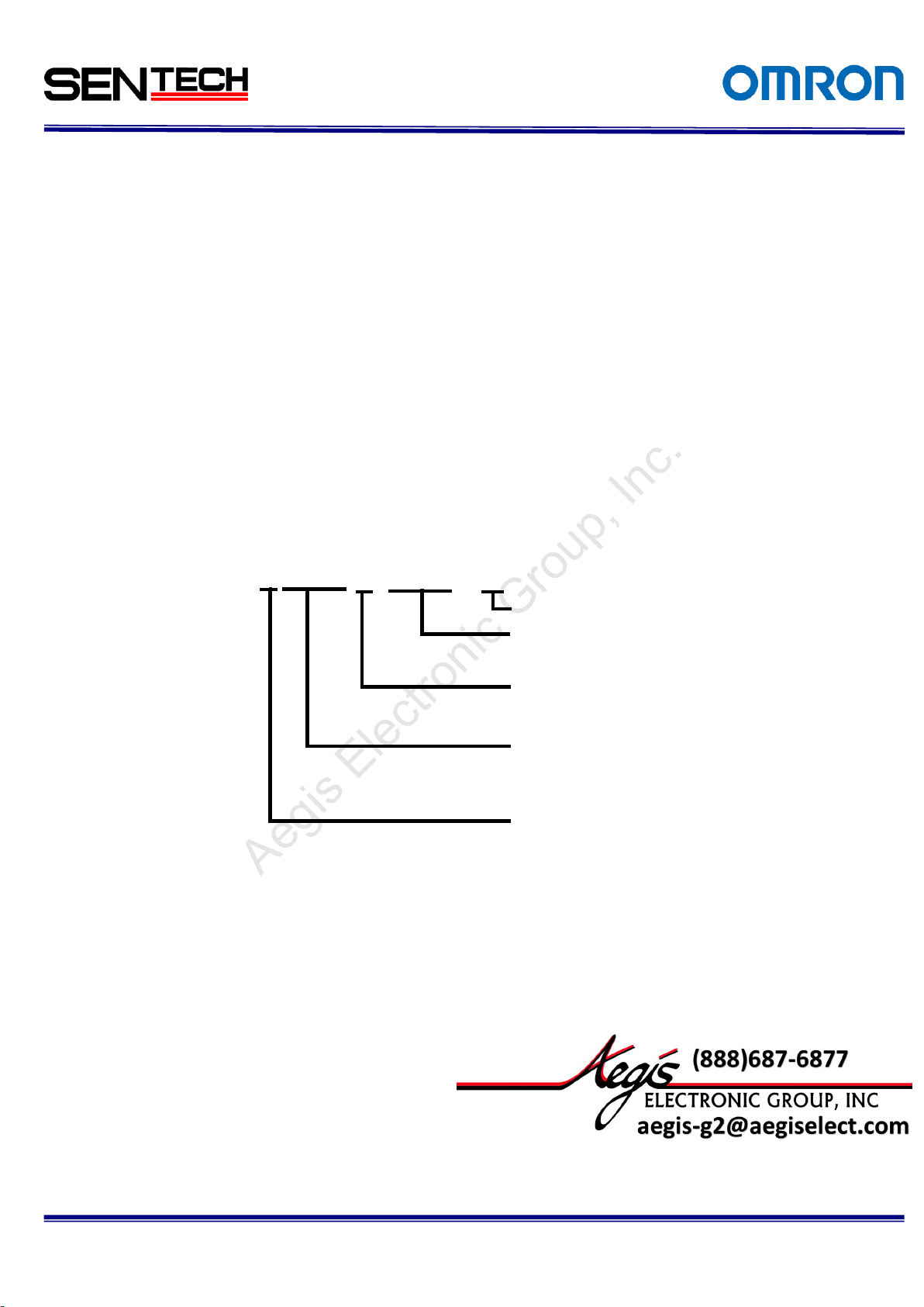
C: Color
M:Monochrome
Resolution
120: 12M Pixel
Sensor Size
A: 1.76”
PCL:PoCL
None: M42 Mount
F: F Mount
For more information please contact Aegis Electronic Group, Inc. *(888)687-6877 *aegis-g2@aegiselect.com *http://www.aegiselect.com
Aegis Electronic Group, Inc.
1 Overview
This document describes the specifications of the following cameras:
STC-CMC120APCL (12M Color)
STC-CMB120APCL (12M Monochrome)
1.1 Features
12M pixel (4096 x 3072)
CMOS Sensor (Global Shutter)
Camera Link (Deca, Full, Medium, Base Configuration)
10,8,4,3,2TAP
PoCL
This Camera Link cameras have 12M pixel CMOS sensor. They support max frame rate 62.3fps on 12M
pixel(8bit, 10TAP mode).
1.2 Naming Method
No.14S056-11
STC-CMx120APCL-x
Figure 1. Naming Method
Page 6
6
STC-CMC120APCL, STC-CMB120APCL
Specifications and Users guide
Product
STC-CMC120APCL
STC-CMB120PCL
Electronic
specifications
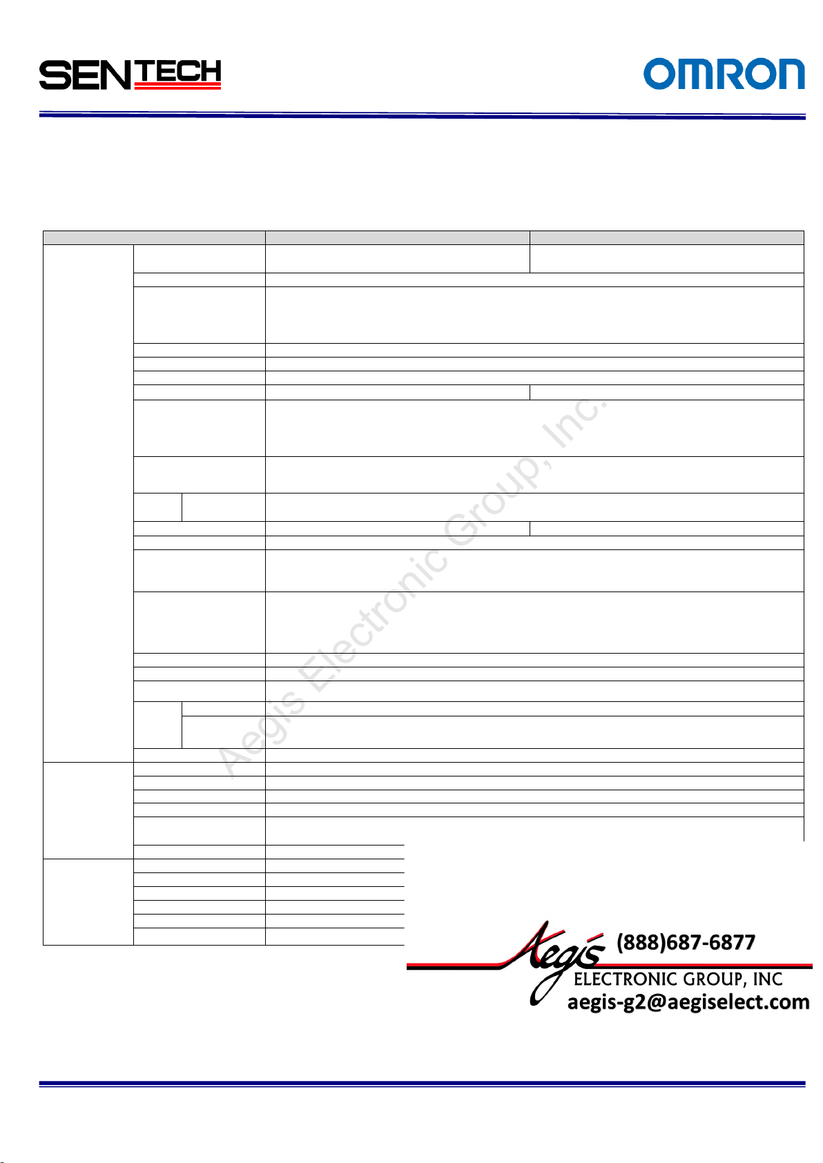
Imager
1.76 “ Type 12Meg color progressive CMOS
(CMOSIS: CMV12000)
1.76” Type 12Meg monochrome progressive
CMOS (CMOSIS: CMV12000)
Shutter
Global Shutter
Active picture elements
4090 (H) x 3072 (V): 10TAP
4096 (H) x 3072 (V): 8TAP,4TAP,2TAP
4092 (H) x 3072 (V): 3TAP
Chip size
22.5 × 16.9 mm
Cell size
5.5 (H) x 5.5 (V) µm
Scanning system
Progressive
Scanning method
Full scanning, Variable AOI
Full scanning, Variable AOI
Frame rate
Vertical frequency of
the Camera Link output
62.3Hz(8bit 10TAP), 51.8Hz (8bit 8TAP),
25.9Hz (8/10/12bit 4TAP), 19.4Hz (8bit 3TAP),
12.9Hz (8/10/12bit 2TAP)
Pixel frequency of
the Camera Link output
10TAP, 8TAP,4TAP,3TAP,2TAP: 85MHz or 42.5MHz (Selectable)
Noise
level
8bit 10TAP
≤ 3.5 Digit (Gain 0 dB)
Minimum scene illumination
Typical 1.4 Lux at F2.25 (10TAP)
Typical 1.2 Lux at F2.25 (10TAP)
Sync. System
Internal
Video output
8bit: 10TAP, Full, Medium, Base Configuration
10bit: Medium, Base Configuration
12bit: Medium, Base Configuration
Shutter speed
8,4,2TAP:41[us] to 207.736 [s] (LINE unit, Pulse Width Trigger), 42[us] to 16.777 [s] (us unit)
10TAP:41[us] to 173.140[s] (LINE unit, Pulse Width Trigger), 42[us] to 16.777 [s] (us unit)
3TAP:42[us] to 277.025[s] (LINE unit, Pulse Width Trigger ), 43[us] to 16.777 [s] ( us unit )
Digital gain
1 to x5
Gamma
1.0
Trigger Mode
Edge Preset Trigger(V Reset), Pulse Width Trigger (V Reset)
Power
Input voltage
12Vdc ± 10%
Consumption
10TAP, Full Configuration: Less than 7.0 W
Base Configuration: Less than 5.2W
Communication
RS232 via Camera Link connector
Mechanical
specifications
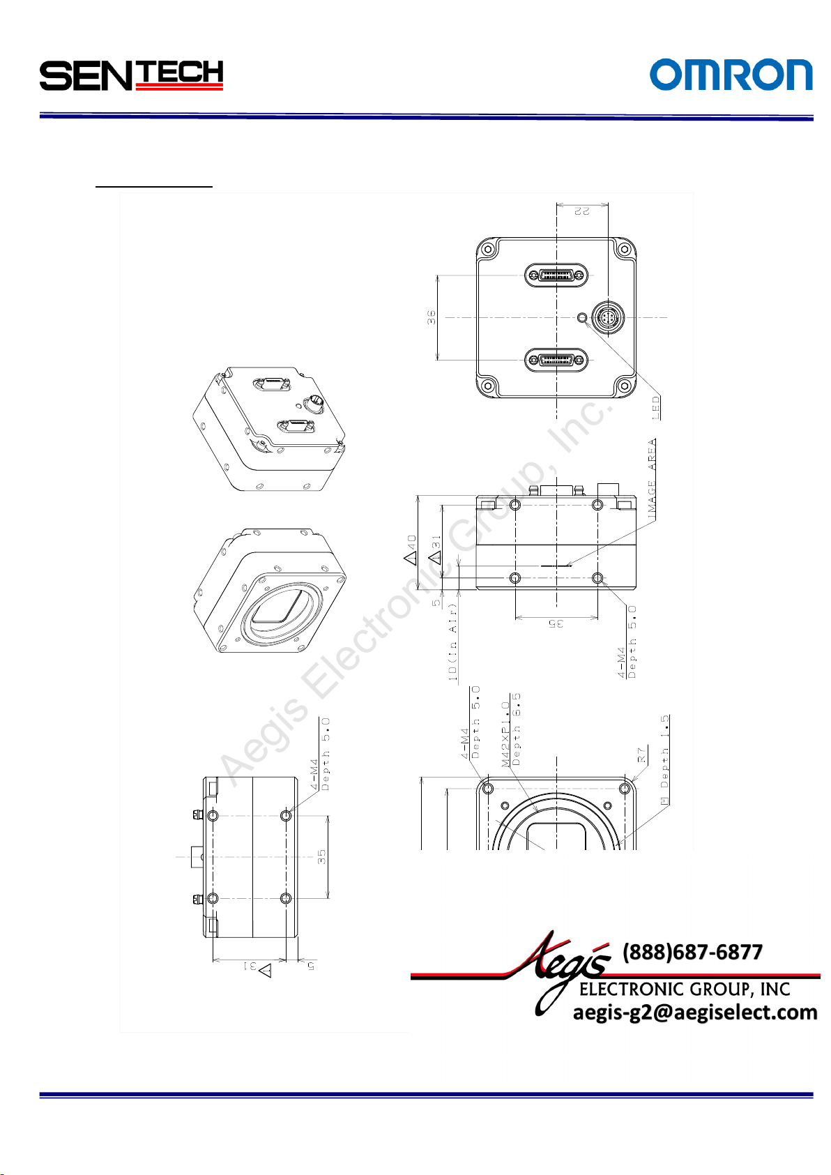
Dimensions
68 (W) x 68 (H) x 40 (D) mm (Excluding the connector)
Optical filter
No IR cut filter
Material
Aluminum alloy
Lens mount
M42 mount (F mount with adopter) FB = 10.0mm(in Air)
Interface connector
Camera Link connector: SDR connector x 2
Power/IO connector: HR10A-7R-6PB (Hirose) or equivalent
Weight
Approximately 305g
Environmental
specifications
Operational
-5 to 40 deg. C
Storage temperature
-30 to 70 deg. C
Vibration
20Hz to 200Hz to 20Hz (5min./cycle), acceleration 10G, XYZ 3 directions 30 min. each)
Shock
Acceleration 38G, half amplitude 6ms, XYZ 3 directions 3times each
Standard compliancy
EMS: EN61000-6-2, EMI: EN55011 (Class A)
RoHS
RoHS compliance
For more information please contact Aegis Electronic Group, Inc. *(888)687-6877 *aegis-g2@aegiselect.com *http://www.aegiselect.com
Aegis Electronic Group, Inc.
2 Specifications
2.1 Electronic specifications / Mechanical specifications / Environmental specifications
2.1.1 STC- CMC120APCL (Color) / STC- CMB120APCL (Monochrome)
Table 1. Specifications
No.14S056-11
Page 7
7
STC-CMC120APCL, STC-CMB120APCL
Specifications and Users guide
For more information please contact Aegis Electronic Group, Inc. *(888)687-6877 *aegis-g2@aegiselect.com *http://www.aegiselect.com
Aegis Electronic Group, Inc.
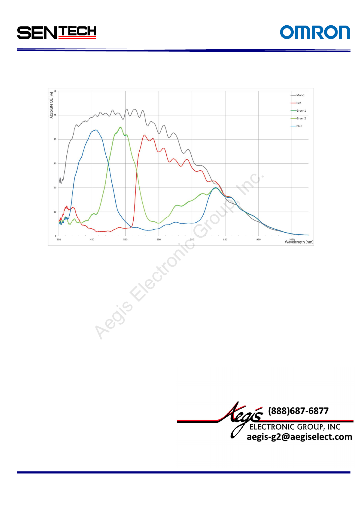
2.2 Spectral Sensitivity Characteristics
2.2.1 STC-CMC120APCL/ STC-CMB120APCL
No.14S056-11
Figure 2. Spectral Sensitivity Characteristics
Page 8
8
STC-CMC120APCL, STC-CMB120APCL
Specifications and Users guide
Pin No.
Signal
Name
Pin No.
Signal
Name
Pin No.
Signal
Name
Pin No.
Signal
Name
1
+12V
14
GND 1
+12V
14
GND 2 X0-
15
X0+ 2
Y0-
15
Y0+ 3 X1-
16
X1+ 3
Y1-
16
Y1+
4
X2-
17
X2+ 4
Y2-
17
Y2+
5
Xclk-
18
Xclk+ 5
Yclk-
18
Yclk+
6
X3-
19
X3+ 6
Y3-
19
Y3+
7
SerTC+
20
SerTC- 7
100Ω
20
100Ω
8
SerTFG-
21
SerTFG+
8 Z0-
21
Z0+
9
CC1- (TRG)
22
CC1+ (TRG)
9 Z1-
22
Z1+
10
CC2+
23
CC2- 10
Z2-
23
Z2+
11
CC3-
24
CC3+ 11
Zclk-
24
Zclk+
12
CC4+
25
CC4- 12
Z3-
25
Z3+
13
GND
26
+12V 13
GND
26
+12V
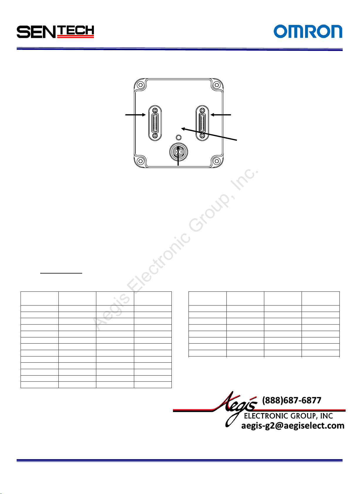
CH1:
26-pin SDR connector
(BaseCamera Link Connector)
CH2
26-pin SDR connector
(Medium / Full Camera
Link Connector)
Power/IO connector
LED
要差替え
For more information please contact Aegis Electronic Group, Inc. *(888)687-6877 *aegis-g2@aegiselect.com *http://www.aegiselect.com
Aegis Electronic Group, Inc.
2.3 Connector specifications
No.14S056-11
Figure 3. Back View
2.3.1 Camera Link connectors:
SDR(3M) equivalent x 2
(CAUTION)
This product is PoCL type.
When the frame grabber board and the cable are applicable for the PoCL, the frame grabber
board supplies the power to the camera. In this case, please DO NOT supply the power from the
Power/IO connector.
Pin assignment
Table 2. CN1:Base Camera Link Connector CN2:Medium/Full Camera Link Connector
Page 9
9
STC-CMC120APCL, STC-CMB120APCL
Specifications and Users guide
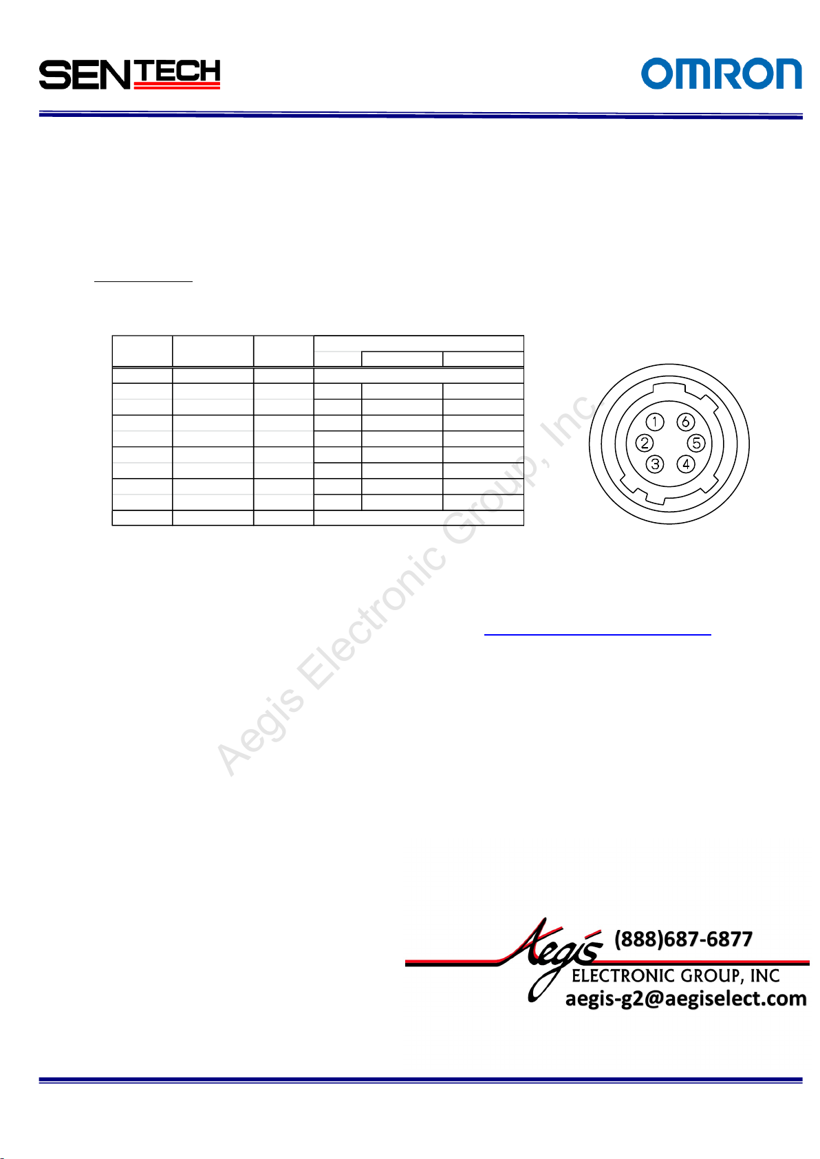
LowVoltage
HighVoltage
1 GND IN
2 SP-4 IN/OUT IN 0 ~ +0.99V +2.3 ~ +3.6V
OUT 0V +3.3V
3 SP-3 IN/OUT IN 0 ~ +0.99V +2.3 ~ +3.6V
OUT 0V +3.3V
4 SP-2 IN/OUT IN 0 ~ +0.99V +2.3 ~ +3.6V
OUT 0V +3.3V
5 SP-1 IN/OUT IN 0 ~ +0.99V +2.3 ~ +3.6V
OUT 0V +3.3V
6 +12Vdc IN
+12Vdc
0V
Pin No
Signal Name
IN/OUT
Voltage
For more information please contact Aegis Electronic Group, Inc. *(888)687-6877 *aegis-g2@aegiselect.com *http://www.aegiselect.com
Aegis Electronic Group, Inc.
2.4 Power/IO connector:
HR10A-7R-6PB (Hirose) or equivalent.
This connector is for 12Vdc power input and the input and output signals.
The trigger input and sync input /output signals can be assigned through the camera setting
communication.
Pin assignment
Table 3. Pin assignment
(Note 1)
Trigger input signal can be assigned either on Camera Link connector (CC1) or on the No. 2 pin of the power/IO
connector through the camera setting communication.
As for the actual method of hardware trigger, please refer to the Using the Trigger Signal through 6pin.
No.14S056-11
Page 10
No.14S056-11
10
STC-CMC120APCL, STC-CMB120APCL
Specifications and Users guide
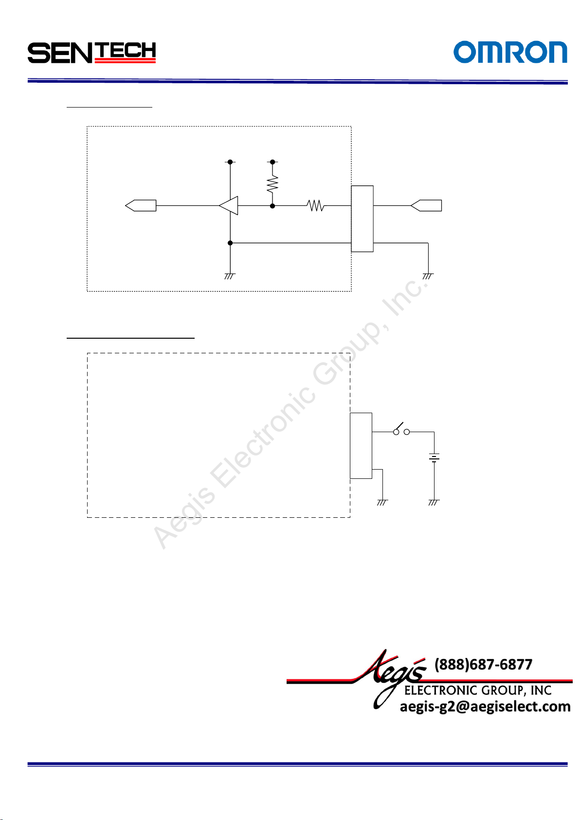
SN74AVC4T774
Camera
input
(to FPGA)
100Ω
+3.3V
GND
User INPUT
Pin. 2 or 3 or 4 or 5
10kΩ
+3.3V
Camera
1
6Pin Conector
2,3,4,
5
TC7WH241FK
100Ω
+3.3V
47kΩ
+3.3V
Camera
input
(to FPGA)
1
6Pin Conector
2,3,4,
5
Input Voltage
0 to +3.6V DC
Pin. 2 or 3 or 4 or 5
Camera
For more information please contact Aegis Electronic Group, Inc. *(888)687-6877 *aegis-g2@aegiselect.com *http://www.aegiselect.com
Aegis Electronic Group, Inc.
Input Signal Circuit
Input Signal Circuit Example
Figure 4. Input Signal Circuit
Figure 5. Input Signal Circuit Example
Page 11
No.14S056-11
11
STC-CMC120APCL, STC-CMB120APCL
Specifications and Users guide
LED
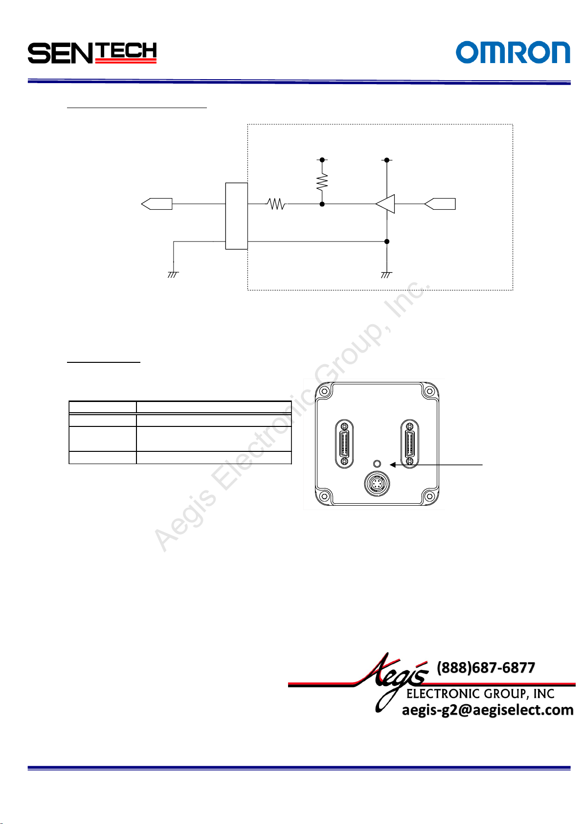
SN74AVC4T774
100Ω
10kΩ
+3.3V
+3.3V
GND
Camera
1
2,3,4,
5
Camera
output
(from FPGA)
Pin. 2 or 3 or 4 or 5
6 Pin Conector
User Output
Voltage 0 to
+3.3V DC
Mode setting
LED
D9H.0 = 1
OFF
Trigger mode
Free run
ON
On 1 second then Off 1 second
(repeatedly)
For more information please contact Aegis Electronic Group, Inc. *(888)687-6877 *aegis-g2@aegiselect.com *http://www.aegiselect.com
Aegis Electronic Group, Inc.
Output Signal Circuit/ Example
LED information
Table 4. LEC Information
Figure 6. Output Signal Circuit Example
Figure 7. LED Location
Page 12
12
STC-CMC120APCL, STC-CMB120APCL
Specifications and Users guide
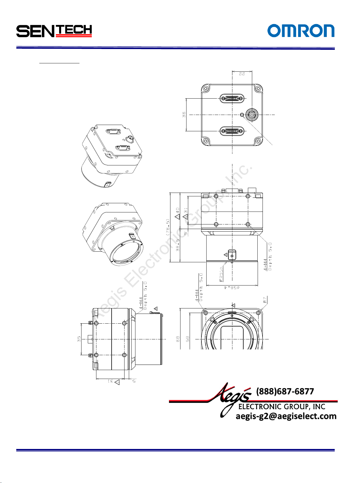
Left and right are same shape
Top and bottom are same shape
For more information please contact Aegis Electronic Group, Inc. *(888)687-6877 *aegis-g2@aegiselect.com *http://www.aegiselect.com
Aegis Electronic Group, Inc.
2.5 Dimensions
M42 Mount Model
No.14S056-11
Figure 8. M42 Mount Model
Page 13
No.14S056-11
13
STC-CMC120APCL, STC-CMB120APCL
Specifications and Users guide
Left and right are same shape
For more information please contact Aegis Electronic Group, Inc. *(888)687-6877 *aegis-g2@aegiselect.com *http://www.aegiselect.com
Aegis Electronic Group, Inc.
F Mount Model
Figure 9. F Mount Model
Page 14

14
STC-CMC120APCL, STC-CMB120APCL
Specifications and Users guide
For more information please contact Aegis Electronic Group, Inc. *(888)687-6877 *aegis-g2@aegiselect.com *http://www.aegiselect.com
Aegis Electronic Group, Inc.
3 Camera Installation
For the installation of this camera, these equipment as bellow are required.
Control software or Serial communication software to access the camera register.
As for using the software, please refer to another chapter.
CONTROL Software. As for accessing the register, please refer to the 6.THE COMMUNICATION PROTOCOL
SPECIFICATIONS.
Camera Link Cable x 2 (SDR Connector : Camera side)
When using on Full Configuration, please use the cable that has qualification.
Frame Graber should support Full, Medium, Base Configuration. When using the PoCL, Frame Graber
should support PoCL.
No.14S056-11
Page 15
15
STC-CMC120APCL, STC-CMB120APCL
Specifications and Users guide
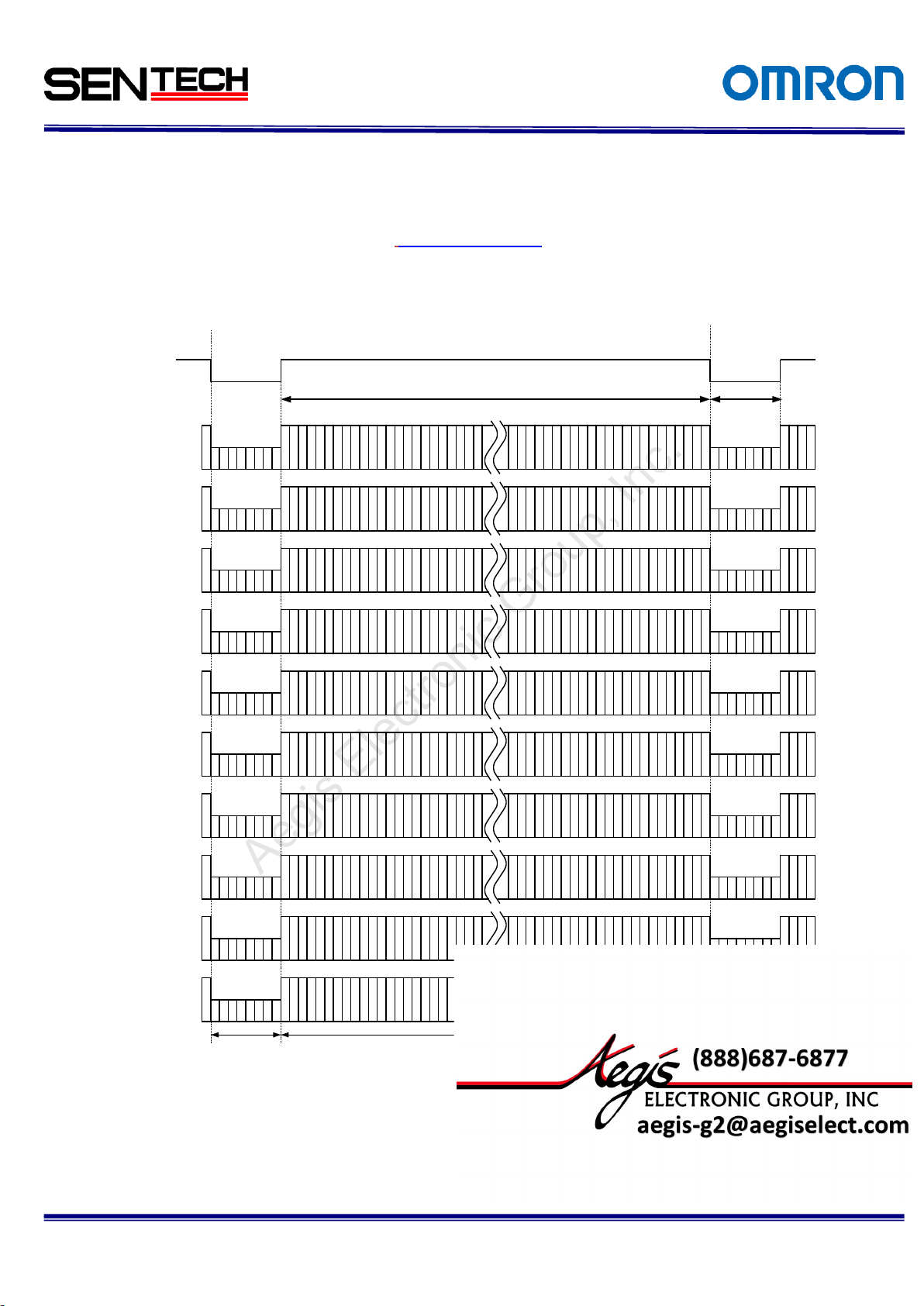
Video out
(Tap1:DA)
LVAL
Horizontal
blanking
One horizontal (1H)
Video output
3
13
23
6
16
26
5
15
25
9
19
29
8
18
28
102030
7
17
27
4
14
24
112131
122232
4062
4072
4082
4064
4074
4084
4068
4078
4088
4061
4071
4081
4063
4073
4083
4065
4075
4085
4066
4076
4086
4069
4079
4089
4067
4077
4087
4070
4080
4090
Video out
(Tap2:DB)
Video out
(Tap6:DF)
Video out
(Tap5:DE)
Video out
(Tap4:DD)
Video out
(Tap3:DC)
Video out
(Tap7:DG)
Video out
(Tap8:DH)
Video out
(Tap9:DI)
Video out
(Tap10:DJ)
409 CLK
28 - 29 CLK
For more information please contact Aegis Electronic Group, Inc. *(888)687-6877 *aegis-g2@aegiselect.com *http://www.aegiselect.com
Aegis Electronic Group, Inc.
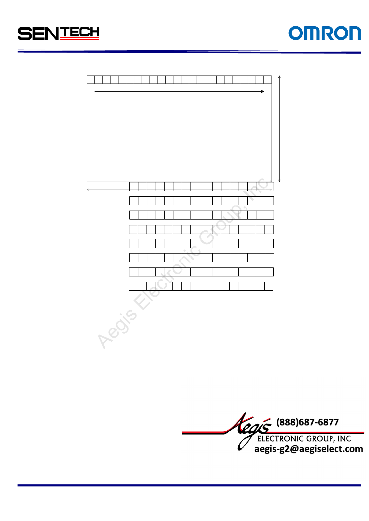
4 The camera output timing charts
4.1 The horizontal timings (CMC120APCL)
As for the vertical timing, please refer to The Vertical timings.
Highs Speed Clock and Low Speed Clock are existed as Pixel Clock.
4.1.1 10 Taps (1X10⁻¹Y) / Horizontal:4,090 pixels
No.14S056-11
1 CLK = 11.764 nseconds (85MHz)
Page 16
16
STC-CMC120APCL, STC-CMB120APCL
Specifications and Users guide
5 15 25 35 ...... 402345 55 65 4033 4043 4053 4063 4073 4083
6 16 26 36 ...... 403346 56 66 4034 4044 4054 4064 4074 4084
8 18 28 38 ...... 402648 58 68 4036 4046 4056 4066 4076 4086
7 17 27 37 ...... 402547 57 67 4035 4045 4055 4065 4075 4085
10 20 30 40 ...... 402850 60 70 4038 4048 4058 4068 4078 4088
12 22 32 42 ...... 403052 62 72 4040 4050 4060 4070 4080 4090
11 21 31 41 ...... 402951 61 71 4039 4049 4059 4069 4079 4089
9 19 29 39 ...... 402749 59 69 4037 4047 4057 4067 4077 4087
14 24 34 44 ...... 402254 64 74 4032 4042 4052 4062 4072 4082
3 13 23 33 ...... 402143 53 63 4031 4041 4051 4061 4071 4081
1 2
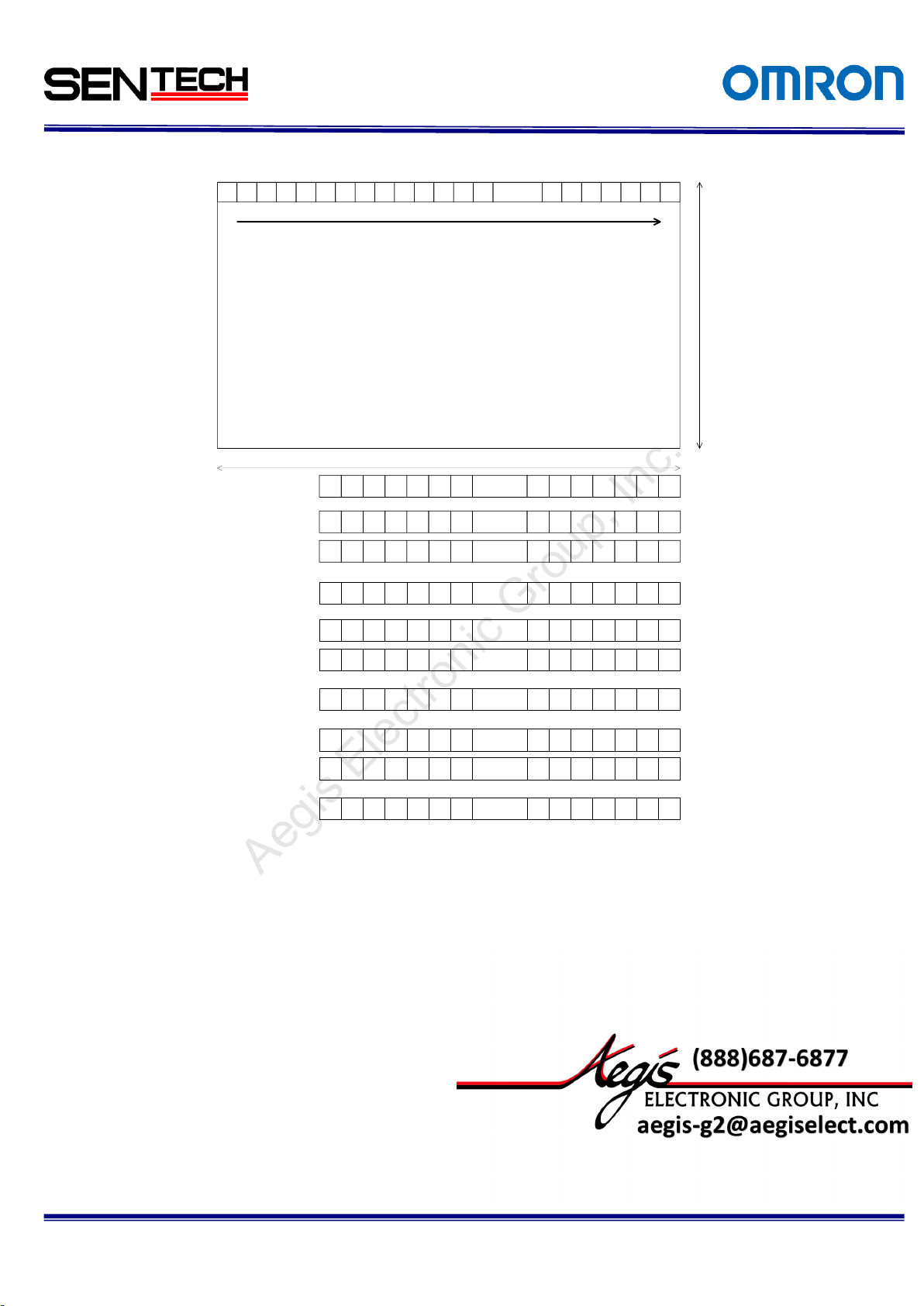
4,090 pixels
3 4 ...... 40845 6 7 8 9 10 11 12 13 14 4085 4086 4087 4088 4089 4090
3,072 lines
For more information please contact Aegis Electronic Group, Inc. *(888)687-6877 *aegis-g2@aegiselect.com *http://www.aegiselect.com
Aegis Electronic Group, Inc.
The pixel order for the Image
TAP1: DA output pixels
TAP2: DB output pixels
TAP3: DC output pixels
TAP4: DD output pixels
TAP5: DE output pixels
TAP6: DF output pixels
TAP7: DG output pixels
TAP8: DH output pixels
TAP9: DG output pixels
TAP10: DH output pixels
No.14S056-11
Page 17
17
STC-CMC120APCL, STC-CMB120APCL
Specifications and Users guide
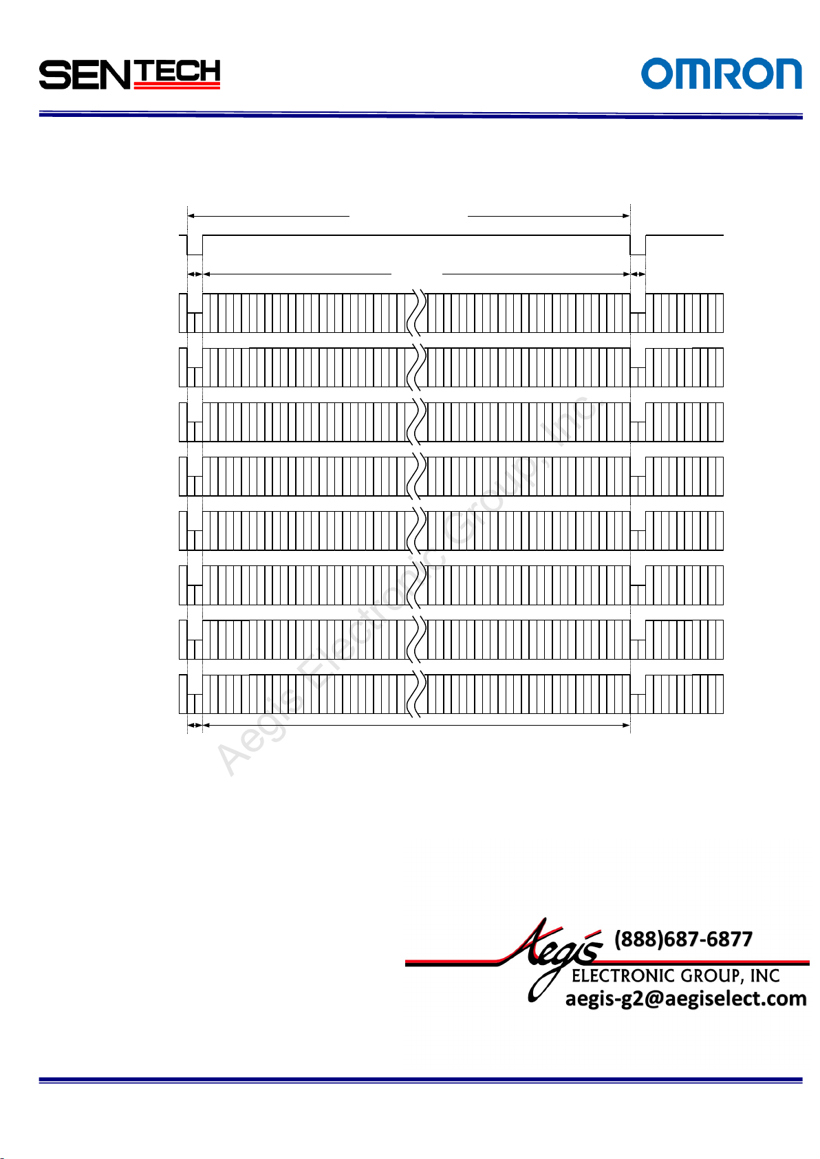
Video out
(Tap1:DA)
LVAL
Horizontal
blanking
H Total(696 - 697clk)
One horizontal (1H)
512 CLK
Video output
14 - 15 CLK
Video out
(Tap2:DB)
Video out
(Tap4:DD)
Video out
(Tap3:DC)
Video out
(Tap5:DE)
Video out
(Tap6:DF)
Video out
(Tap7:DG)
Video out
(Tap8:DH)
4087
4091
4095
4084
4088
4092
4086
4090
4094
4085
4089
4093
4088
4092
4096
4080
4084
4091
4079
4083
4090
4078
4082
4089
5
13
21
6
14
22
8
16
24
7
15
23
4
12
20
3
11
19
1
9
17
2
10
18
For more information please contact Aegis Electronic Group, Inc. *(888)687-6877 *aegis-g2@aegiselect.com *http://www.aegiselect.com
Aegis Electronic Group, Inc.
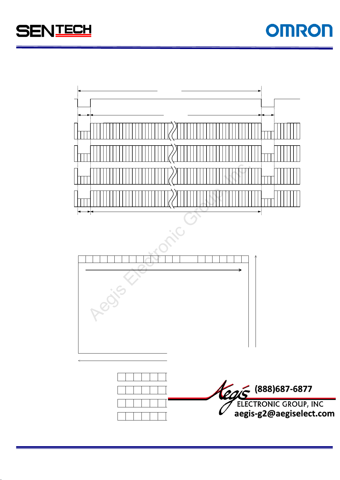
4.1.2 8 Taps (1X8-1Y) / Horizontal 4,096 pixels
No.14S056-11
1 CLK = 11.764 nseconds(85MHz)
1 CLK = 23.524 nseconds(42.5MHz)
Page 18
18
STC-CMC120APCL, STC-CMB120APCL
Specifications and Users guide
1 2
4,096 pixels
3 4 ...... 40905 6 7 8 9 10 11 12 13 14 4091 4092 4093 4094 4095 4096
3,072 lines
1 9 17 25 ...... 404133 41 49 4049 4057 4065 4073 4081 4089
2 10 18 26 ...... 404234 42 50 4050 4058 4066 4074 4082 4090
4 12 20 28 ...... 404436 44 52 4052 4060 4068 4076 4084 4092
3 11 19 27 ...... 404335 43 51 4051 4059 4067 4075 4083 4091
6 14 22 30 ...... 404638 46 54 4054 4062 4070 4078 4086 4094
8 16 24 32 ...... 404840 48 56 4056 4064 4072 4080 4088 4096
7 15 23 31 ...... 404739 47 55 4055 4063 4071 4079 4087 4095
5 13 21 29 ...... 404537 45 53 4053 4061 4069 4077 4085 4093
For more information please contact Aegis Electronic Group, Inc. *(888)687-6877 *aegis-g2@aegiselect.com *http://www.aegiselect.com
Aegis Electronic Group, Inc.
The pixel order for the Image
TAP1: DA output pixels
TAP2: DB output pixels
TAP3: DC output pixels
TAP4: DD output pixels
TAP5: DE output pixels
TAP6: DF output pixels
TAP7: DG output pixels
TAP8: DH output pixels
No.14S056-11
Page 19
19
STC-CMC120APCL, STC-CMB120APCL
Specifications and Users guide
Video out
(Tap1: DA)
LVAL
Horizontal
blanking
1032 CLK
One horizontal (1H)
1024 CLK
Video output
28 - 29 CLK
Video out
(Tap2: DB)
Video out
(Tap3: DC)
Video out
(Tap4: DD)
159
4086
4090
4094
2
6
10
3
7
11
4
8
12
4085
4089
4093
4087
4091
4095
4088
4092
4096
1 2
4,096 pixels
3 4 ...... 40905 6 7 8 9 10 11 12 13 14 4091 4092 4093 4094 4095 4096
3,072 lines
1 5 9 13 ...... 406917 21 25 4073 4077 4081 4085 4089 4093
2 6 10 14 ...... 407018 22 26 4074 4078 4082 4086 4090 4094
3 7 11 15 ...... 407119 23 27 4075 4079 4083 4087 4091 4095
4 8 12 16 ...... 407220 24 28 4076 4080 4084 4088 4092 4096
For more information please contact Aegis Electronic Group, Inc. *(888)687-6877 *aegis-g2@aegiselect.com *http://www.aegiselect.com
Aegis Electronic Group, Inc.
4.1.3 4 Taps (1X4-1Y) / Horizontal:4,096 pixels
The pixel order for the Image
TAP1: DA output pixels
TAP2: DB output pixels
TAP3: DC output pixels
TAP4: DD output pixels
1 CLK = 11.764 nseconds(85MHz)
1 CLK = 23.524 nseconds(42.5MHz)
No.14S056-11
Page 20

20
STC-CMC120APCL, STC-CMB120APCL
Specifications and Users guide
1 3 5 7 ...... 40839 11 13 4085 4087 4089 4091 4093 4095
1 2
4,096 pixels
3 4 ...... 40905 6 7 8 9 10 11 12 13 14 4091 4092 4093 4094 4095 4096
3,072 lines
Video out
(Tap 1: DA)
LVAL
Horizontal
blanking
1,032 CLK
One horizontal (1H)
1,024 CLK
Video output
56-57 CLK
Video out
(Tap 2: DB)
135
246
2043
2045
2047
2044
2046
2048
Video out
(Tap1:DA)
LVAL
Horizontal
blanking
1403 or 1404 CLK
One horizontal (1H)
1364 CLK
Video output
39 or 40 CLK
Video out
(Tap2:DB)
Video out
(Tap3:DC)
2 4 6 8 ...... 408410 12 14 4086 4088 4090 4092 4094 4096
For more information please contact Aegis Electronic Group, Inc. *(888)687-6877 *aegis-g2@aegiselect.com *http://www.aegiselect.com
Aegis Electronic Group, Inc.
4.1.4 3 Taps (1X3-1Y) / Horizontal 4,092 pixels
4.1.5 2 Taps (1X2-1Y) / Horizontal:4,096 pixels
The pixel order for the Image
TAP1: DA output pixels
TAP2: DB output pixels
1 CLK = 11.764 nseconds(85MHz)
1 CLK = 23.524 nseconds(42.5MHz)
1 CLK = 11.764 nseconds(85MHz)
1 CLK = 23.524 nseconds(42.5MHz)
No.14S056-11
Page 21

21
STC-CMC120APCL, STC-CMB120APCL
Specifications and Users guide
Mode
(EEH)
Tap
Number
Configuration
CameraLink Output PixelClock
Frequency(MHz)
Horizontal
Pixel (Pixel)
FPS[fps]
Camera Link
Output Bit
0 2 Base
85.0
42.5
4096
12.9
6.4
8/10/12
16 3 Base
85.0
42.5
4092
19.4
9.8
8
1 4 MEDIUM
85.0
42.5
4096
25.9
12.9
8/10/12
2 8 FULL
85.0
42.5
4096
51.8
25.9
8
3
10
DECA
85.0
42.5
4090
62.3
31.1
8
Video out
FVAL
Vertical blanking
3110 H
One vertical (1V)
3072 H38H(Min)
Video output
1
2
3071
3072
38 H(Min)
For more information please contact Aegis Electronic Group, Inc. *(888)687-6877 *aegis-g2@aegiselect.com *http://www.aegiselect.com
Aegis Electronic Group, Inc.
4.2 The Vertical timings
As for Horizontal timing, please refer to the The horizontal timings (CMC120APCL).
Three Video scan modes exist. The detail for these three scan modes are described as below.
Full scan: All of line and pixel output from the camera
Binning: Averaged pixel value output from the camera
Subsampling: Skipped the lines and pixels output from the camera
Overview of Full scan
All of the lines and pixels are output and the entire image is shown. For transmitting the image,
some configurations will not be supported, or can drop the frame rate.
4.3 Full Scan (TC-CMC120APCL / STC-CMB120APCL)
Table of Video Output on Full Scan mode (STC-CMC120APCL / STC-CMB120APCL)
No.14S056-11
Page 22

22
STC-CMC120APCL, STC-CMB120APCL
Specifications and Users guide
AOI_A
AOI_B
AOI_C
AOI_D
VAHA
A0-A1h
HASA
B0-B1h
VASA
90-91h
VAHB
A2-A3h
VASB
92-93h
VAHC
A4-A5h
VASC
94-95h
VAHD
A6-A7h
VASD
96-97h
HASB
B2-B3h
HASC
B4-B5h
HASD
B6-B7h
4096
3072
HAWA
C0-C1h
HAWB
C2-C3h
HAWC
C4-C5h
HAWD
C6-C7h
For more information please contact Aegis Electronic Group, Inc. *(888)687-6877 *aegis-g2@aegiselect.com *http://www.aegiselect.com
Aegis Electronic Group, Inc.
4.4 AOI Output Timing
This camera can be set the AOI up to 8.
Variable Partial Start Line(VAS*), Variable Partial Effective Line(VAH*), Horizontal Start
Position(HAS*), Horizontal Effective Pixel(HAW*) can be set for each eight regions. One region can
be set on horizontal direction. And vertical area can not be overlapped for each region.
As follows setting is the example of four area of interest (AOI)
No.14S056-11
Page 23

No.14S056-11
23
STC-CMC120APCL, STC-CMB120APCL
Specifications and Users guide
FVAL
AOI_A
AOI_B
AOI_C
AOI_D
LVAL
LVAL
LVAL
LVAL
For more information please contact Aegis Electronic Group, Inc. *(888)687-6877 *aegis-g2@aegiselect.com *http://www.aegiselect.com
Aegis Electronic Group, Inc.
Camera Link Output timing on AOI is as follow.
AOI images output as consecutive image.
Horizontal pixel number can be reduced through Horizontal Effective Pixel(HAW*) on AOI.
AOI on Color camera
Variable Partial Start Line(VAS*), Variable Partial Effective Line(VAH*) can be set two lines each.
Horizontal Start Position(HAS*), Horizontal Effective Pixel(HAW*) can be set two pixels each.
Frame rate on AOI
Maximum frame rate can be achieved through Variable Partial Effective Line(VAH*).
Horizontal Effective Pixel(HAW*) is not relate to maximum frame rate.
Page 24

No.14S056-11
24
STC-CMC120APCL, STC-CMB120APCL
Specifications and Users guide
For more information please contact Aegis Electronic Group, Inc. *(888)687-6877 *aegis-g2@aegiselect.com *http://www.aegiselect.com
Aegis Electronic Group, Inc.
Formula of maximum frame rate
・10TAP CameraLink Clock: 85MHz
50 / 258 / Variable Partial Effective Line(VAH*) +38) x 10^6 [fps] (Round down numbers beyond the second decimal point)
・10TAP CameraLink Clock: 42.5MHz
25 / 258 / Variable Partial Effective Line(VAH*)+38) x 10^6 [fps] (Round down numbers beyond the second decimal point)
・8TAP CameraLink Clock: 85MHz
41.6 / 258 / Variable Partial Effective Line(VAH*)+38) x 10^6 [fps] (Round down numbers beyond the second decimal point)
・8TAP CameraLink Clock: 42.5MHz, 4TAP CameraLink Clock: 85MHz
20.8 / 258 / Variable Partial Effective Line(VAH*)+38) x 10^6 [fps] (Round down numbers beyond the second decimal point)
・4TAP CameraLink Clock: 42.5MHz, 2TAP CameraLink Clock: 85MHz
10.4 / 258 / Variable Partial Effective Line(VAH*)+38) x 10^6 [fps] (Round down numbers beyond the second decimal point)
・2TAP CameraLink Clock: 42.5MHz
5.2 / 258 / Variable Partial Effective Line(VAH*)+38) x 10^6 [fps] (Round down numbers beyond the second decimal point)
・3TAP CameraLink Clock: 85MHz
15.6 / 258 / Variable Partial Effective Line(VAH*)+38) x 10^6 [fps] (Round down numbers beyond the second decimal point)
・3TAP CameraLink Clock: 42.5MHz
7.8 / 258 / Variable Partial Effective Line(VAH*)+38) x 10^6 [fps] (Round down numbers beyond the second decimal point)
Page 25

25
STC-CMC120APCL, STC-CMB120APCL
Specifications and Users guide
DA5
DA4 DA3 DA2 DA1 DA0
DB0DB1
DB2DB3
DB4DB5
LVALFVAL
DA6DA7
DB6DB7
X0
X1
X2
X3
XCLK
DA1 DA0
DB0DB1
DA5
10TAP8bit
DC5 DC4 DC3
DC2
DC1 DC0
DD0
DD1
DD2DD3DD4DD5
DC6
DC7
DD6
DD7
Y0
Y1
Y2
Y3
YCLK
DD2DD3
DC3DC4
DE1
DE2DE3
DE4DE5 LVAL
DE2DE3
DF5
DF4
DF3 DF2
DF1 DF0
DF5DF6
DE6DE7
LVALDD7
DE0
DF6DF7DG0
DG1
DG2DG3DG4
DG5DG6DG7
Z0
Z1
Z2
Z3
ZCLK
DG5DG6 DH1
DH2
DH3DH4
DH5
LVAL
DH5
DH2
DH6
DH7
DH0
DJ0DJ1
DI1DI3DI4
DI0DI5DI6
DI2DI7
DJ1DJ3
DJ4
DJ0DJ5DJ6 DJ2DJ7
DD1
LVAL
DH6
For more information please contact Aegis Electronic Group, Inc. *(888)687-6877 *aegis-g2@aegiselect.com *http://www.aegiselect.com
Aegis Electronic Group, Inc.
4.5 Camera Link bit assignment
DA0 to DA7: 8bit data for one pixel from TAP1
DB0 to DB7: 8bit data for one pixel from TAP2
DC0 to DC7: 8bit data for one pixel from TAP3
DD0 to DD7: 8bit data for one pixel from TAP4
DE0 to DE7: 8bit data for one pixel from TAP5
DF0 to DF7: 8bit data for one pixel from TAP6
DG0 to DG7: 8bit data for one pixel from TAP7
DH0 to DH7: 8bit data for one pixel from TAP8
DI0 to DI7: 8bit data for one pixel from TAP9
DJ0 to DJ7: 8bit data for one pixel from TAP10
No.14S056-11
Page 26

26
STC-CMC120APCL, STC-CMB120APCL
Specifications and Users guide
DA5 DA4 DA3 DA2 DA1 DA0DB0
DB1DB2DB3DB4DB5
LVALFVALDVAL
SP DA6DA7DB6DB7
X0
X1
X2
X3
XCLK
DA1 DA0
DB1DB2
DA6DA7
8TAP8bit
DC5 DC4 DC3 DC2
DC1 DC0
DD0DD1DD2DD3DD4DD5
SP
DC6DC7
DD6DD7
Y0
Y1
Y2
Y3
YCLK
DD0DD1
DC2DC3
DE1DE2DE3DE4DE5
LVALFVALDVAL
DE1DE2
DF5 DF4 DF3 DF2
DF1 DF0
DF2DF3
DE6DE7DD6DD7
DE0
DF6DF7
DG0DG1DG2DG3DG4DG5
SP DG6DG7
Z0
Z1
Z2
Z3
ZCLK
DG0DG1
DH1DH2DH3DH4DH5
LVALFVALDVAL
DH1DH2
DH6DH7DG6DG7
DH0
NCNC NC NC NC NC
NC NC
NC NC
For more information please contact Aegis Electronic Group, Inc. *(888)687-6877 *aegis-g2@aegiselect.com *http://www.aegiselect.com
Aegis Electronic Group, Inc.
DA0 to DA7: 8bit data for one pixel from TAP1
DB0 to DB7: 8bit data for one pixel from TAP2
DC0 to DC7: 8bit data for one pixel from TAP3
DD0 to DD7: 8bit data for one pixel from TAP4
DE0 to DE7: 8bit data for one pixel from TAP5
DF0 to DF7: 8bit data for one pixel from TAP6
DG0 to DG7: 8bit data for one pixel from TAP7
DH0 to DH7: 8bit data for one pixel from TAP8
No.14S056-11
Page 27

27
STC-CMC120APCL, STC-CMB120APCL
Specifications and Users guide
X0
X1
X2
X3
XCLK
4TAP8bit
Y0
Y1
Y2
Y3
YCLK
DA5 DA4 DA3 DA2 DA1 DA0DB0
DB1DB2DB3DB4DB5
LVALFVALDVAL
SP DA6DA7DB6DB7
DA1 DA0
DB1DB2
DA6DA7
DC5 DC4 DC3 DC2
DC1 DC0
DC6DC7
DC2DC3
DD0DD1DD2DD3DD4DD5
SP DD6DD7
DD0DD1
LVALFVALDVAL
DE1DE2
DF2DF3
DD6DD7
NC
NC NC NC NC NC NC NC
NC NC NC NC
NC NC NC NC
DA8 DA5 DA4 DA3 DA2 DA1 DA0
DA9DB8DB9DB0DB1 DB8DB9
DB2DB3DB4DB5LVALFVALDVAL
SP DA6DA7DB6DB7
X0
X1
X2
X3
XCLK
DA1 DA0
DA9
DB2DB3
DA6DA7
4TAP10bit
NC NC
NC NC
NC
DC8 DC5 DC4 DC3 DC2 DC1
DC0
DC9
DD8DD9
DD0DD1DD2DD3DD4DD5
LVALFVALDVAL
SP DC6DC7 DD6DD7
Y0
Y1
Y2
Y3
YCLK
DC1
DD0DD1
NC NC
NC NC
NC NC
DC2
DD6DD7
DA8 DA5 DA4 DA3 DA2 DA1 DA0
DA9DB8DB9DB0DB1 DB8DB9
DB2DB3DB4DB5LVALFVALDVAL
SP DA6DA7DB6DB7
X0
X1
X2
X3
XCLK
DA1 DA0
DA9
DB2DB3
DA6DA7
4TAP12bit
NC NC
NC NC
NC
DC8 DC5 DC4 DC3 DC2 DC1
DC0
DC9
DD8DD9
DD0DD1DD2DD3DD4DD5
LVALFVALDVAL
SP DC6DC7 DD6DD7
Y0
Y1
Y2
Y3
YCLK
DC1
DD0DD1
NC NC
DC2
DD6DD7
DB11 DB10
DA11 DA10DA10
DD10DD11
DC10DC11
For more information please contact Aegis Electronic Group, Inc. *(888)687-6877 *aegis-g2@aegiselect.com *http://www.aegiselect.com
Aegis Electronic Group, Inc.
No.14S056-11
DA0 to DA7:8bit data for one pixel from TAP1 DA0 to DA9: 10bit data for one pixel from TAP1
DB0 to DB7: 8bit data for one pixel from TAP2 DB0 to DB9: 10bit data for one pixel from TAP2
DC0 to DC7: 8bit data for one pixel from TAP3 DC0 to DC9: 10bit data for one pixel from TAP3
DD0 to DD7: 8bit data for one pixel from TAP4 DD0 to DD9: 10bit data for one pixel from TAP4
DA0 to DA11:10bit data for one pixel from TAP1
DB0 to DB11:10bit data for one pixel from TAP2
DC0 to DC11:10bit data for one pixel from TAP3
DD0 to DD11:10bit data for one pixel from TAP4
Page 28

28
STC-CMC120APCL, STC-CMB120APCL
Specifications and Users guide
DA8 DA5 DA4 DA3 DA2 DA1 DA0
DA9DB8DB9DB0DB1 DB8DB9
DB2DB3DB4DB5LVALFVALDVAL
SP DA6DA7DB6DB7
X0
X1
X2
X3
XCLK
DA1 DA0
DA9
DB2DB3
DA6DA7
2TAP10bit
NC NC
NC NC
NC
DA5 DA4 DA3 DA2 DA1 DA0DB0
DB1DB2DB3DB4DB5
LVALFVALDVAL
SP DA6DA7DB6DB7
X0
X1
X2
X3
XCLK
DA1 DA0
DB1DB2
DA6DA7
2TAP8bit
NC
NC
NC NC
NC NC NC
NC
NCNC
DA8 DA5 DA4 DA3 DA2 DA1 DA0
DA9DB8DB9DB0DB1 DB8DB9
DB2DB3DB4DB5LVALFVALDVAL
SP DA6DA7DB6DB7
X0
X1
X2
X3
XCLK
DA1 DA0
DA9
DB2DB3
DA6DA7
2TAP12bit
NC NC
NC NC
NC
DB11 DB10
DA10DA11
DA0 to DA7: 8bit data for one pixel from TAP1
DB0 to DB7: 8bit data for one pixel from TAP2
DA0 to DA9: 10bit data for one pixel from TAP1
DB0 to DB9: 10bit data for one pixel from TAP2
DA0 to DA11: 12bit data for one pixel from TAP1
DB0 to DB11: 12bit data for one pixel from TAP2
X0
X1
X2
X3
XCLK
3TAP8bit
DA5 DA4 DA3 DA2 DA1 DA0DB0
DB1DB2DB3DB4DB5
LVALFVALDVAL
SP DA6DA7DB6DB7
DA1 DA0
DB1DB2
DA6DA7
DC5 DC4 DC3 DC2
DC1 DC0
DC6DC7
DC2DC3
DA0 to DA7: 8bit data for one pixel from TAP1
DB0 to DB7: 8bit data for one pixel from TAP2
DC0 to DC7: 8bit data for one pixel from TAP3
For more information please contact Aegis Electronic Group, Inc. *(888)687-6877 *aegis-g2@aegiselect.com *http://www.aegiselect.com
Aegis Electronic Group, Inc.
No.14S056-11
Page 29

29
STC-CMC120APCL, STC-CMB120APCL
Specifications and Users guide
XW-3YHXW-2
YH
XW-6
YH
XW-1
YH
XW
YH
XW-4
YH
XW-5
YH
XW-7
YH
XW-8
YH
XW-9
YH
X10
YH
X9
YH
X8
YH
X7
YH
X6
YH
X5
YH
X4
YH
X3
YH
X2
YH
X1
YH
Tap3
Tap2
Tap1
Tap4
Tap5
Tap6
Tap7
Tap8
Tap9
Tap10
Sep X =10
Sep Y =1
X1Y1X2Y1X3
Y1
X4Y1X5Y1X6
Y1
X1Y2X2Y2X3
Y2
X4Y2X5Y2X6
Y2
X7Y2X8Y2X9
Y2
X10
Y2
X7Y1X8Y1X9
Y1
X10
Y1
X1
YH-1X2YH-1X3YH-1
X4
YH-1X5YH-1X6YH-1
X7
YH-1X8YH-1X9YH-1
X10
YH-1
XW-9
YH-1
XW-8
YH-1
XW-7
YH-1
XW-6
YH-1
XW-5
YH-1
XW-4
YH-1
XW-3
YH-1
XW-2
YH-1
XW-1
YH-1
XW
YH-1
XW
Y1
XW
Y2
XW-1
Y1
XW-2
Y1
XW-3
Y1
XW-4
Y1
XW-5
Y1
XW-6
Y1
XW-7
Y1
XW-8
Y1
XW-9
Y1
XW-1
Y2
XW-2
Y2
XW-3
Y2
XW-4
Y2
XW-5
Y2
XW-6
Y2
XW-7
Y2
XW-8
Y2
XW-9
Y2
XW
YH
XW-1
YH
XW-2
YH
XW-3
YH
X8
YH
X7
YH
X6
YH
X5
YH
X4
YH
X3
YH
X2
YH
X1
YH
Tap1
Tap2
Tap3
Tap4
Tap5
Tap6
Tap7
Tap8
Sep X = 8
Sep Y = 1
XW-4
YH
XW-5
YH
XW-6
YH
XW-7
YH
XW
Y1
XW
Y2
XW-1
Y2
XW-1
Y1
XW-2
Y1
XW-2
Y2
XW-3
Y2
XW-3
Y1
XW-4
Y1
XW-4
Y2
XW-5
Y2
XW-5
Y1
XW-6
Y1
XW-6
Y2
XW-7
Y1
XW-7
Y2
XW-7
YH-1
XW-6
YH-1
XW-5
YH-1
XW-4
YH-1
XW-3
YH-1
XW-2
YH-1
XW-1
YH-1
X1
YH-1X2YH-1X3YH-1X4YH-1
X8
YH-1
X6
YH-1X7YH-1
X5
YH-1
X1
Y1
X1
Y2
X2Y1X3Y1X4
Y1
X2Y2X3Y2X4Y2X5Y2X6Y2X7Y2X8
Y2
X5Y1X6Y1X7Y1X8
Y1
XW
YH-1
For more information please contact Aegis Electronic Group, Inc. *(888)687-6877 *aegis-g2@aegiselect.com *http://www.aegiselect.com
Aegis Electronic Group, Inc.
4.6 Camera Link TAP Geometry
4.6.1 10TAP (1X10⁻¹Y)
No.14S056-11
4.6.2 8TAP (1X8-1Y)
Page 30

30
STC-CMC120APCL, STC-CMB120APCL
Specifications and Users guide
XW
YH
XW-1
YH
XW-2
YH
XW-3
YH
X4
YH
X3
YH
X2
YH
X1
YH
Tap1
Tap2
Tap3
Tap4
Sep X = 4
Sep Y = 1
X1
YH-1X2YH-1
X3
YH-1X4YH-1
XW
YH-1
XW-2
YH-1
XW-1
YH-1
XW-3
YH-1
X1
Y1
X1
Y2
X2
Y1
X3
Y1
X4
Y1
X2
Y2
X3
Y2
X4
Y2
XW-3Y2XW-2
Y2
XW-1Y2XW
Y2
XW-3Y1XW-2
Y1
XW-1Y1XW
Y1
XW
YH
XW-1
YH
X2
YH
X1
YH
Tap1
Sep X = 2
Sep Y = 1
X1
YH-1X2YH-1
XW
YH-1
XW-1
YH-1
X1
Y1
X1
Y2
X2
Y1
X2
Y2
XW-1Y2XW
Y2
XW-1Y1XW
Y1
Tap2
For more information please contact Aegis Electronic Group, Inc. *(888)687-6877 *aegis-g2@aegiselect.com *http://www.aegiselect.com
Aegis Electronic Group, Inc.
4.6.3 4TAP (1X4-1Y)
No.14S056-11
4.6.4 2TAP (1X2-1Y)
Page 31

31
STC-CMC120APCL, STC-CMB120APCL
Specifications and Users guide
G G B G G R R
B
For more information please contact Aegis Electronic Group, Inc. *(888)687-6877 *aegis-g2@aegiselect.com *http://www.aegiselect.com
Aegis Electronic Group, Inc.
4.7 Bayer pattern for color model (Only STC-CMC120APCL)
No.14S056-11
Page 32

32
STC-CMC120APCL, STC-CMB120APCL
Specifications and Users guide
E x p o s u r e
t i m e
I n t e r n a l V D
CCD
e x p o s u r e
V i d e o o u t
For more information please contact Aegis Electronic Group, Inc. *(888)687-6877 *aegis-g2@aegiselect.com *http://www.aegiselect.com
Aegis Electronic Group, Inc.
5 Camera function modes
5.1 Normal mode
5.1.1 Normal mode (Electronic shutter)
No.14S056-11
Page 33

33
STC-CMC120APCL, STC-CMB120APCL
Specifications and Users guide
Trigger signal
Exposure time
Exposure time: T1' = T1 + α 1 *Note2
T1
1.5us
Filtering *Note.1
T1'
Exposure
time
Internal VD
exposure
Trigger signal
(Positive)
Video out
*Note. 1
FVAL
For more information please contact Aegis Electronic Group, Inc. *(888)687-6877 *aegis-g2@aegiselect.com *http://www.aegiselect.com
Aegis Electronic Group, Inc.
5.2 Pulse width trigger mode
In this trigger mode with positive polarity, the camera exposure starts at the rising edge of the trigger pulse and stops
at the falling edge of the trigger pulse. Therefore, In the case of the exposure positive polarity is selected, the
exposure periods are the high states of the trigger pulse.
5.2.1 Pulse width trigger mode
Note.1: The exposure time sets by the pulse width of the trigger signal. No FVAL output without any trigger signal.
5.2.2 Pulse Width Trigger mode (Exposure timing)
Note.1: The trigger signal is removed by the filtering if the pulse width of the input trigger signal is less than 1.5us.
Please input the trigger signal has more than 1.5 us pulse width.
Note.2: α1(Exposure time offset) is.
10,8,4,2TAP
41[us] (Edge Preset and Variable at Line unit)
42[us] (Pulse Width and Variable at us unit)
3TAP
42[us] (Edge Preset and Variable at Line unit)
43[us] (Pulse Width and Variable at us unit)
No.14S056-11
Page 34

34
STC-CMC120APCL, STC-CMB120APCL
Specifications and Users guide
Exposure
time
Internal VD
exposure
Trigger signal
(Rising edge)
Video out
*Note. 1
FVAL
Trigger signal
Exposure time
T1'
Exposure time: T1' = Preset electronic shutter + α 1
Filtering *Note.1
1.5us
For more information please contact Aegis Electronic Group, Inc. *(888)687-6877 *aegis-g2@aegiselect.com *http://www.aegiselect.com
Aegis Electronic Group, Inc.
5.3 Edge Preset Trigger mode
In this trigger mode, the camera exposure starts at the rising edge of the trigger pulse or negative edge when setting
is “Trigger Polarity::Negative”, the camera exposure starts at the falling edge of the trigger pulse.
Exposure duration time is preset by the “Electrical Shutter” settings.
.
5.3.1 Edge Preset Trigger mode
Note.1: The exposure time sets by the preset electronic shutter speed.
5.3.2
5.3.3 Edge Preset Trigger mode (Exposure timing)
Note.1: The trigger signal is removed by the filtering if the pulse width of the input trigger signal is less than 1.5us.
Please input the trigger signal has more than 1.5 us pulse width.
Note.2: α1(Exposure time offset) is.
10,8,4,2TAP
41[us] (Edge Preset and Variable at Line unit)
42[us] (Pulse Width and Variable at us unit)
3TAP
42[us] (Edge Preset and Variable at Line unit)
43[us] (Pulse Width and Variable at us unit)
No.14S056-11
Page 35

35
STC-CMC120APCL, STC-CMB120APCL
Specifications and Users guide
Settings
Baud rate 9,600bps / 38,400bps /57,600bps / 115,200bps
Data bit 8bit
Parity None
Stop bit 1bit
Flow control None
For more information please contact Aegis Electronic Group, Inc. *(888)687-6877 *aegis-g2@aegiselect.com *http://www.aegiselect.com
Aegis Electronic Group, Inc.
6 The communication protocol specifications
This camera has the communication function that enables external devises like PC control the camera functions.
Please use “CLCtrl2 (Version1.01 or later)” communication software or use following the communication protocol to
communicate to the camera.
Note.
The communication problem may occur under the following conditions:
1. When the external sync frequency is illegal (more than 1% off from the specified frequency).
2. When external sync is unstable (In another word the bad external sync signal).
3. About for one second after switching from/to external sync mode to/from internal sync mode.
4. About for one second after switching frame rate.
6.1 The communication method
UART (RS232C), Binary communication
6.2 The communication settings
No.14S056-11
Page 36

36
STC-CMC120APCL, STC-CMB120APCL
Specifications and Users guide
SOF Data length Data EOF
(8bit) (8bit) (Data length byte) (8bit)
SOF Device code Read Page selection Command code Data length Data EOF
(8bit) (6bit) (1bit) (1bit) (8bit) (8bit) (1byte) (8bit)
Name
SOF
Device code
Read / Write
Page selection
Command
code
Data length
Data
The value of the data is depending on the command
Sets (or gets) the value is as “03H” always
End of the frame
Result of the sending command
Sending data
The data length is 1 byte when send read command.
The data length is depending on the command when send write command.
EOF
Receiving code
The camera rejects other commands while the data of the EEPROM is being replaced
Please refer from the following page.
(approximately 5 msec. / byte).
Data length (Unit: byte)
The data length is depending on the command after sent read command.
Receiving data
The data length is “00H” after sent write command.
The data of the EEPROM is replaced by sent data when sent write command.
The camera sends the receiving coce as "01H" to the PC after the data of the EEPROM is replaced.
Sets (or gets) the value is as “02H” always.
Sets (or gets) “1” when send write command.
Sets “0” when access to the command register of the camera
The data of the command register is replaced by the sent data when sent write command.
The data of the EEPROM is not replaced.
Sets “1” when access to the EEPROM of the camera
The camera works with the data of the EEPROM when the power on the camera.
Gets the data from the EEPROM when sent read.
Start of the frame
Descriptions
Sets the device code of the camera is as “000000”.
Sets (or gets) “0” when send read command.
Gets current data from the command register when sent read command.
SOF Device code Write Page selection Command code Data length Data EOF
(8bit) (6bit) (1bit) (1bit) (8bit) (8bit) (Data length byte) (8bit)
SOF Data length Receiving code EOF
(8bit) (8bit) "00" (8bit) (8bit)
01H: OK (ACK), 10H: Receiving problem (NAC),
11H: Communication problem 14H: TimeOut
For more information please contact Aegis Electronic Group, Inc. *(888)687-6877 *aegis-g2@aegiselect.com *http://www.aegiselect.com
Aegis Electronic Group, Inc.
6.3 The communication format
A. The sending data format from the PC to the camera is as follows:
a. Send the read command
b. Send the write command
B. The receiving data format from the camera is as follows:
a. After sent the read command
b. After sent the write command
C. Descriptions of the format
D. Example command
Send the read command to read the 00H address data of the register
No.14S056-11
02, 00, 00, 01, 00, 03
SOF, (Device code/Read/Register), Command code, Data length, Data, EOF
The return command
02, 01, 00, 03
Page 37

37
STC-CMC120APCL, STC-CMB120APCL
Specifications and Users guide
Command
No.
Read
/Write
Save to
EEPROM
Function
Initial
Data
Data Range
09-0FH
Reserved
- 10H
R/W
O
The camera function mode 1 (8bit: D[7..0])
1 11H
R/W
O
The camera function mode 2 (8bit: D[7..0])
08H 12H
R/W
O
The camera function mode 3 (8bit: D[7..0])
50H 13H
Reserved
- 14H
R/W
O
The communication mode (8bit: D[7..0])
0 15-1FH
Reserved
- 20H
R/W
O
The exposure time of the electronic shutter (16bit: D[7..0])
1.536
1 to
16,777,215
21H
R/W
O
The exposure time of the electronic shutter (16bit: D[15..8])
22H
R/W
O
The exposure time of the electronic shutter (16bit: D[23..16])
23-27H
Reserved
- 28H
R/W
O
The delay time for the trigger (8bit: D[7..0])
0
0 to 255
29-30H
Reserved
- - 31H
R/W
O
The digital gain (8bit: D[7..0])
0
-
32-37H
Reserved
- 38H
R/W
O
The clamp level (8bit: D[7..0])
40
0 to 80
39H
Reserved
- - 3AH
R/W
O
White Balance R gain (8bit: D[7..0])
0
0 to 255
3BH
R/W
O
White Balance B gain (8bit: D[7..0])
0
0 to 255
3CH
R/W
O
White Balance Gr gain (8bit: D[7..0])
0
0 to 255
3DH
R/W
O
White Balance Gb gain (8bit: D[7..0])
0
0 to 255
3E-46H
Reserved
- 47H
R/W
O
HDR / Number of Slopes
1 48-4AH
Reserved
- 4BH
R/W
O
PGA (8bit: D[7..0])
0 4C-55H
Reserved
- 56H
R/W
O
Knee1 Point
1 57H
R/W
O
Knee2 Point
1 58-5AH
Reserved
- 5BH
R/W
Vlow2 Volt
64
64 to 127
5CH
R/W
Vlow3 Volt
64
64 to 127
5D-67H
Reserved
- 68H
R/W
O
Horizontal Flip
0 78H
R/W
O
Test Pattern (8bit: D[7..0])
0 79H
R/W
O
Image effect selection (8bit: D[7..0])
0 7A-7FH
Reserved
-
80H
R/W
O
EEPROM Control (8bit: D[7..0])
0
0 or 1
81H
R/W
O
Factory Default Load (8bit: D[7..0])
0
0 or 170
82-8FH
Reserved
-
For more information please contact Aegis Electronic Group, Inc. *(888)687-6877 *aegis-g2@aegiselect.com *http://www.aegiselect.com
Aegis Electronic Group, Inc.
6.4 The camera control commands
6.4.1 The camera commands list(Device Code:00H)
Note. 1: The data unit of the each command is 1byte (8bit).
Note. 2: The data can be saved to the EEPROM if “x” in the “Save to EEPROM” column in the list.
The camera is operating with the data of the EEPROM when the power on the camera.
No.14S056-11
Page 38

No.14S056-11
38
STC-CMC120APCL, STC-CMB120APCL
Specifications and Users guide
Command
No.
Read
/Write
Save to
EEPROM
Function
Initial
Data
Data
Range
90H
R/W
O
The start line of the variable partial scanning A (16bit: D[7..0])
0 0 to 3,068
91H
R/W
O
The start line of the variable partial scanning A (16bit: D[15..8])
92H
R/W
O
The start line of the variable partial scanning B (16bit: D[7..0])
0 0 to 3,068
93H
R/W
O
The start line of the variable partial scanning B (16bit: D[15..8])
94H
R/W
O
The start line of the variable partial scanning C (16bit: D[7..0])
0 0 to 3,068
95H
R/W
O
The start line of the variable partial scanning C (16bit: D[15..8])
96H
R/W
O
The start line of the variable partial scanning D (16bit: D[7..0])
0 0 to 3,068
97H
R/W
O
The start line of the variable partial scanning D (16bit: D[15..8])
98H
R/W
O
The start line of the variable partial scanning E (16bit: D[7..0])
0 0 to 3,068
99H
R/W
O
The start line of the variable partial scanning E (16bit: D[15..8])
9AH
R/W
O
The start line of the variable partial scanning F (16bit: D[7..0])
0 0 to 3,068
9BH
R/W
O
The start line of the variable partial scanning F (16bit: D[15..8])
9CH
R/W
O
The start line of the variable partial scanning G (16bit: D[7..0])
0 0 to 3,068
9DH
R/W
O
The start line of the variable partial scanning G (16bit: D[15..8])
9EH
R/W
O
The start line of the variable partial scanning H (16bit: D[7..0])
0 0 to 3,068
9FH
R/W
O
The start line of the variable partial scanning H (16bit: D[15..8])
A0H
R/W
O
The effective lines of the variable partial scanning A (16bit: D[7..0])
3072
4 to 3072
A1H
R/W
O
The effective lines of the variable partial scanning A (16bit: D[15..8])
A2H
R/W
O
The effective lines of the variable partial scanning B (16bit: D[7..0])
0
0 to 3072
A3H
R/W
O
The effective lines of the variable partial scanning B (16bit: D[15..8])
A4H
R/W
O
The effective lines of the variable partial scanning C (16bit: D[7..0])
0
0 to 3072
A5H
R/W
O
The effective lines of the variable partial scanning C (16bit: D[15..8])
A6H
R/W
O
The effective lines of the variable partial scanning D (16bit: D[7..0])
0
0 to 3072
A7H
R/W
O
The effective lines of the variable partial scanning D (16bit: D[15..8])
A8H
R/W
O
The effective lines of the variable partial scanning E (16bit: D[7..0])
0
0 to 3072
A9H
R/W
O
The effective lines of the variable partial scanning E (16bit: D[15..8])
AAH
R/W
O
The effective lines of the variable partial scanning F (16bit: D[7..0])
0
0 to 3072
ABH
R/W
O
The effective lines of the variable partial scanning F (16bit: D[15..8])
ACH
R/W
O
The effective lines of the variable partial scanning G (16bit: D[7..0])
0
0 to 3072
ADH
R/W
O
The effective lines of the variable partial scanning G (16bit: D[15..8])
AEH
R/W
O
The effective lines of the variable partial scanning H (16bit: D[7..0])
0
0 to 3072
AFH
R/W
O
The effective lines of the variable partial scanning H (16bit: D[15..8])
For more information please contact Aegis Electronic Group, Inc. *(888)687-6877 *aegis-g2@aegiselect.com *http://www.aegiselect.com
Aegis Electronic Group, Inc.
Page 39

No.14S056-11
39
STC-CMC120APCL, STC-CMB120APCL
Specifications and Users guide
Command
No.
Read
/Write
Save to
EEPROM
Function
Initial
Data
Data
Range
B0H
R/W
O
The start Pixel of the variable partial scanning A (16bit: D[7..0])
0
0 to 4095
B1H
R/W
O
The start Pixel of the variable partial scanning A (16bit: D[15..8])
B2H
R/W
O
The start Pixel of the variable partial scanning B (16bit: D[7..0])
0
0 to 4095
B3H
R/W
O
The start Pixel of the variable partial scanning B (16bit: D[15..8])
B4H
R/W
O
The start Pixel of the variable partial scanning C (16bit: D[7..0])
0
0 to 4095
B5H
R/W
O
The start Pixel of the variable partial scanning C (16bit: D[15..8])
B6H
R/W
O
The start Pixel of the variable partial scanning D (16bit: D[7..0])
0
0 to 4095
B7H
R/W
O
The start Pixel of the variable partial scanning D (16bit: D[15..8])
B8H
R/W
O
The start Pixel of the variable partial scanning E (16bit: D[7..0])
0
0 to 4095
B9H
R/W
O
The start Pixel of the variable partial scanning E (16bit: D[15..8])
BAH
R/W
O
The start Pixel of the variable partial scanning F (16bit: D[7..0])
0
0 to 4095
BBH
R/W
O
The start Pixel of the variable partial scanning F (16bit: D[15..8])
BCH
R/W
O
The start Pixel of the variable partial scanning G (16bit: D[7..0])
0
0 to 4095
BDH
R/W
O
The start Pixel of the variable partial scanning G (16bit: D[15..8])
BEH
R/W
O
The start Pixel of the variable partial scanning H (16bit: D[7..0])
0
0 to 4095
BFH
R/W
O
The start Pixel of the variable partial scanning H (16bit: D[15..8])
C0H
R/W
O
The effective Pixel of the variable partial scanning A (16bit: D[7..0])
4096
0 to 4096
C1H
R/W
O
The effective Pixel of the variable partial scanning A (16bit: D[15..8])
C2H
R/W
O
The effective Pixel of the variable partial scanning B (16bit: D[7..0])
0
0 to 4096
C3H
R/W
O
The effective Pixel of the variable partial scanning B (16bit: D[15..8])
C4H
R/W
O
The effective Pixel of the variable partial scanning C (16bit: D[7..0])
0
0 to 4096
C5H
R/W
O
The effective Pixel of the variable partial scanning C (16bit: D[15..8])
C6H
R/W
O
The effective Pixel of the variable partial scanning D (16bit: D[7..0])
0
0 to 4096
C7H
R/W
O
The effective Pixel of the variable partial scanning D (16bit: D[15..8])
C8H
R/W
O
The effective Pixel of the variable partial scanning E (16bit: D[7..0])
0
0 to 4096
C9H
R/W
O
The effective Pixel of the variable partial scanning E (16bit: D[15..8])
CAH
R/W
O
The effective Pixel of the variable partial scanning F (16bit: D[7..0])
0
0 to 4096
CBH
R/W
O
The effective Pixel of the variable partial scanning F (16bit: D[15..8])
CCH
R/W
O
The effective Pixel of the variable partial scanning G (16bit: D[7..0])
0
0 to 4096
CDH
R/W
O
The effective Pixel of the variable partial scanning G (16bit: D[15..8])
CEH
R/W
O
The effective Pixel of the variable partial scanning H (16bit: D[7..0])
0
0 to 4096
CFH
R/W
O
The effective Pixel of the variable partial scanning H (16bit: D[15..8])
D0-DDH
Reserved
- DEH
R/W
O
Pixel Blemish Correction Mode1 (8bit: D[7..0])
1 DFH
R/W
O
Pixel Blemish Correction Mode2 (8bit: D[15..8])
70H
-
E0-E2H
Reserved
E3H
FPN Correction Mode (8bit: D[7..0])
17 - 0 or 17
E4-EDH
Reserved
EEH
Camera Operation Mode (16bit: D[7..0])
0
0 to 3
or 16
EFH
Camera Operation Mode (16bit: D[15..8])
F0-FFH
Reserved
For more information please contact Aegis Electronic Group, Inc. *(888)687-6877 *aegis-g2@aegiselect.com *http://www.aegiselect.com
Aegis Electronic Group, Inc.
Page 40

No.14S056-11
40
STC-CMC120APCL, STC-CMB120APCL
Specifications and Users guide
Command No.
Command Descriptions
10H:
MOD1[7..0]
[The camera function mode 1] Initial data: MOD1[7..0] = 01H
Sets the camera function mode.
D[7..0]
D7
D6
D5
D4
D3
D2
D1
D0
D7:
No function
Set always as "0"
D6:
Trigger polarity
0: Positive
1: Negative
D5:
Trigger mode
0: Edge preset
1: Pulse width
D4 to D1:
No function
Sets always as "0000"
D0:
Exposure time unit
0: Line Unit
1: usec Unit
11H:
MOD2[7..0]
[The camera function mode 2] Initial data:MOD2[7..0] = 08H
Sets the camera function mode.
D[7..0]
D7
D6
D5
D4
D3
D2
D1
D0
D7:
No function
Sets always as "0"
D6 to D5:
No function
00: 85MHz
10: 42.5MHz
01,11: No function
(Prohibited setting. Do not set these values)
D4:
No function
Sets always as "0"
D3:
Function mode
0: Trigger mode
1: Continuous mode
D2 to D0:
No function
Sets always as "000"
* No video output without the trigger signal input while the camera works with the trigger mode.
12H:
MOD3[7..0]
[The camera function mode 3] Initial data: MOD3[7..0] = 50H
Sets the camera function mode.
D[7..0]
D7
D6
D5
D4
D3
D2
D1
D0
D7 to D6
Video out
00: 10bit
10: 12bit , *12H
01: 8bit
11: No function
D5:
Trigger signal input connector
0: Camera Link (CC1)
1: Power/IO connector(No. 2 pin,
SP4)
D4:
Exposure start mode
0: Normal
1: Horizontal Synchronization
D3 to D0:
No function
Sets always as "000"
14H:
UART [7..0]
[The communication mode] Initial data: UART[7..0] = 01H
Sets the communication mode.
D[7..0]
D7
D6
D5
D4
D3
D2
D1
D0
D7 to D2
No function
Sets always as "000000"
D1 to D0:
Communication mode
00: 38,400bps
01: 9,600bps
10: 57,600bps
11: 115,200bps
For more information please contact Aegis Electronic Group, Inc. *(888)687-6877 *aegis-g2@aegiselect.com *http://www.aegiselect.com
Aegis Electronic Group, Inc.
6.4.2 Description of the camera control commands (The under line settings are the factory default settings)
Page 41

No.14S056-11
41
STC-CMC120APCL, STC-CMB120APCL
Specifications and Users guide
Command No.
Command Descriptions
20H:
SVR[7..0]
21H:
SVR[15..8]
22H:
SVR[23..16]
[The exposure time of the electronic shutter] Initial data: SVR[23..0] = 1,536, Range: 1 to 16,777,215
Sets the preset shutter speed for electronic shutter.
D[7..0]
D7
D6
D5
D4
D3
D2
D1
D0
Case 10h.0 =0 (Exposure time on Usec unit)
・10TAP
Exposure time (shutter speed) = ((SVR[23..0] -1) x 258 + 1020 ) x 10 / 250 Unit: usec
・8,4,2TAP
Exposure time (shutter speed) = ((SVR[23..0]-1) X 258 + 851) x 10 / 250 Unit: usec
*Minimum shutter speed with Pulse Width Trigger on Line unit is up to 41useconds
・3TAP
Exposure time (shutter speed) = ((SVR[23..0]-1) X 258 + 647 ) x 10 / 187.5 Unit: usec
*Minimum shutter speed with Pulse Width Trigger on Line unit is up to 42useconds
10h.0=1 (Exposure time on Usec unit)
Exposure time (shutter speed) = 1 X SVR[] Unit: usec
*Minimum shutter speed on Usec unit is
10,8,4,2TAP
up to 42useconds
3TAP
up to 43useconds
28H:
DLY[7..0]
[The delay time for the trigger] Initial data: :DLY[7..0] = 0、Range: 0 to 255
Sets the delay time that is from the trigger signal input to start exposure.
Delay time = 2us X DLY[7..0] (useconds)
31H:
DGB[7..0]
[The digital gain] Initial data: DGB[7..0] = 0
Video level = (Input video level - CLAMP[7..0]) X (1 + DGB[7..0] / 64) + CLAMP[7..0]
CLAMP[7..0]:The clamp level (The value of the address 38H)
38H:
CLAMP[7..0]
[The clamp level] Initial data: CLAMP[7..0] = 40、Range: :0 to 80
Sets the clamp level (The clamp level of the black signal).
This value is as 10bit video image. When 8bit is selected, clamp level should be 1/4 of setting value.
3AH:
WBR[7..0]
[White Blance R Gain] Initial data: WBR[7..0] = 0、Range: 0to255
Set the Red gain on Bayer
Video level = (Input video level - CLAMP[7..0]) X (1 + WBR[7..0] / 64) + CLAMP[7..0]
3BH:
WBB[7..0]
[White Blance B Gain] Initial data: WBB[7..0] = 0、Range: 0to255
Set the Blue gain on Bayer
Video level = (Input video level - CLAMP[7..0]) X (1 + WBB[7..0] / 64) + CLAMP[7..0]
3CH:
WBGR[7..0]
[White Blance GR Gain] Initial data: WBGR[7..0] = 0、Range: 0to255
Set the Green gain on Bayer GR line
Video level = (Input video level - CLAMP[7..0]) X (1 + WBGR[7..0] / 64) + CLAMP[7..0]
3DH:
WBGB[7..0]
[White Blance GB Gain] Initial data: WBGB[7..0] = 0、Range: 0to255
Set the Green gain on Bayer GB line
Video level = (Input video level - CLAMP[7..0]) X (1 + WBGB[7..0] / 64) + CLAMP[7..0]
For more information please contact Aegis Electronic Group, Inc. *(888)687-6877 *aegis-g2@aegiselect.com *http://www.aegiselect.com
Aegis Electronic Group, Inc.
Page 42

No.14S056-11
42
STC-CMC120APCL, STC-CMB120APCL
Specifications and Users guide
Command No.
Command Descriptions
47H:
HDR[7..0]
[HDR] Initial data: HDR[7..0] = 1
Set the Slope number on HDR.
D[7..0]
D7
D6
D5
D4
D3
D2
D1
D0
D7 to D6:
D5 to D2:
D1 to D0:
HDR Mode
No function
Number of Slopes
0:Disable,
Sets always as "0000"
3:Enable
0:No function
1:No function
2:2 Slopes
3:3 Slopes
4BH:
PGA[7..0]
[PGA] Initial data: PGA[7..0] = 0
Sets the gain for adjust the brightness.
D[7..0]
D7
D6
D5
D4
D3
D2
D1
D0
D7:
D6 to D5:
No function
PGA Gain
Sets always as "0"
0:x1.0 gain
3:x1.4 gain
1:x1.2 gain
4:x1.6 gain
D4 to D0:
No function
Sets always as "00000"
56H:
KN1P [7..0]
[Knee1 parameter] Initial data: KN1P[7..0] = 1, Range: 0 to 254
Sets the exposure time for the electronic shutter for the knee1 point, as for the exposure time.
HDR[7..0]:47H should be set 2 Slopes or 3 Slopes
Knee1 Exp = EXPTA[23..0] X KN1P[7..0] / 256
※EXPTA[23..0]:22Hto20H
57H:
KN2P [7..0]
[Knee2] Initial data: KN2P [7..0] = 1, Range: 0 to 254
Sets the exposure time for the electronic shutter for the knee2 point, as for the exposure time.
Parameter should be set as % of exposure time.
HDR[7..0]:47H should be set 3 Slopes
Knee2 Exp = EXPTA[23..0] X KN1P[7..0] / 256
※EXPTA[23..0]:22Hto20H
5BH:
Vlow2 [7..0]
[Vlow2] Initial data: Vlow2 [7..0] = 64, Range: 64 to 127
Sets the Vlow2 voltage for the HDR saturation level voltage.
HDR[7..0]:47H should be set 2 Slopes or 3 Slopes
5CH:
Vlow3 [7..0]
[Vlow3] Initial data: Vlow2 [7..0] = 64, Range: :64 to 127
Sets the Vlow3 voltage for the HDR saturation level voltage.
HDR[7..0]:47H should be set 3 Slopes
68H:
[7..0]
[Reverse mode] Initial data: [7..0] = 0
Sets the image output direction.
D[7..0]
D7
D6
D5
D4
D3
D2
D1
D0
D7 to D6:
No Function
Always set as “00”
D5:
Vertical mirror image
0: Normal image
1: Vertical mirror image
D4:
Horizontal mirror image
0: Normal image
1:Horizontal mirror image
D3 to D0:
No Function
Always set as “0000”
For more information please contact Aegis Electronic Group, Inc. *(888)687-6877 *aegis-g2@aegiselect.com *http://www.aegiselect.com
Aegis Electronic Group, Inc.
Page 43

No.14S056-11
43
STC-CMC120APCL, STC-CMB120APCL
Specifications and Users guide
Command No.
Command Descriptions
78H:
TESTP[7..0]
[Test Pattern] Initial data: TESTP [7..0] = 00H
Sets the test pattern video output.
D[7..0]
D7
D6
D5
D4
D3
D2
D1
D0
D7 to D5:
0: Normal Video Image
1: Gray Scale
2: Ramp
3: 100% White
4: White Clip
6: Color Bar(RGB BAYER)
Others: Black
79H:
EFFCT[7..0]
[Image effect selection] Initial data: EFFCT[7..0] = 00H
Sets the image effect.
Image data depends on Tap number of CameraLink output. If the value is not enough, drop off the value.
When horizontal start pixel position is larger than actual number, horizontal start pixel position should be set 0.
D[7..0]
D7
D6
D5
D4
D3
D2
D1
D0
D7:
Negative / Positive video selection
0: Positive image
1: Negative image
D6 to D0:
Image effect
00H: No effect (Original)
01H: 9bit gradation
02H: 9bit gradation
03H: 7bit gradation
04H: 6bit gradation
05H: 5bit gradation
06H: 4bit gradation
07H: 3bit gradation
08H: 2bit gradation
09H: 1bit gradation
0A to 7FH: No Function
(Prohibited settings. Do not set these values)
80H:
E2P[7..0]
[EEPROM control] Initial data: E2P[7..0] = 0
D[7..0]
D7
D6
D5
D4
D3
D2
D1
D0 D7 to D1:
No function
Always set as “0000000”
D0:
Write control to the EEPROM
0: Prohibited
1: Accept
Note: This bit is cleared to “0” automatically by the internal processes after the execution of the command.
81H:
INI[7..0]
[Reload camera default setting] Initial data: INI [7..0] = 00H
Sets the factory setting.
D[7..0]
D7
D6
D5
D4
D3
D2
D1
D0
Note: Once reloaded the camera setting, this register may set “0” automatically. setting data does not save on
EEPROM through this register.
D[7..0]:
Factory Setting
0: No Function
170: Reload factory setting
For more information please contact Aegis Electronic Group, Inc. *(888)687-6877 *aegis-g2@aegiselect.com *http://www.aegiselect.com
Aegis Electronic Group, Inc.
Page 44

No.14S056-11
44
STC-CMC120APCL, STC-CMB120APCL
Specifications and Users guide
Command No.
Command Descriptions
90H:
VASA[7..0]
91H:
VASA[15..8]
[Vertical AOI Start Line AOI_A] Initial data: :VASA[15..0] = 0、Range: 0 to 3,068
Sets Vertical AOI Start Line AOI_A.
The value should be set 4 Lines each.
(e.g.:0、4、8、to 3,068)
92H:
VASB[7..0]
93H:
VASB[15..8]
[Vertical AOI Start Line AOI_B] Initial data: :VASB[15..0] = 0、Range: 0 to 3,068
Sets Vertical AOI Start Line AOI_B.
Sets Vertical AOI Start Line AOI_A.
The value should be set 4 Lines each.
(e.g.:0、4、8、to 3,068)
94H:
VASC[7..0]
95H:
VASC[15..8]
[Vertical AOI Start Line AOI_C] Initial data: :VASC[15..0] = 0、Range: 0 to 3,068
Sets Vertical AOI Start Line AOI_C.
Sets Vertical AOI Start Line AOI_A.
The value should be set 4 Lines each.
(e.g.:0、4、8、to 3,068)
96H:
VASD[7..0]
97H:
VASD[15..8]
[Vertical AOI Start Line AOI_D] Initial data: :VASD[15..0] = 0、Range: 0 to 3,068
Sets Vertical AOI Start Line AOI_D.
Sets Vertical AOI Start Line AOI_A.
The value should be set 4 Lines each.
(e.g.:0、4、8、to 3,068)
98H:
VASE[7..0]
99H:
VASE[15..8]
[Vertical AOI Start Line AOI_E] Initial data: :VASE[15..0] = 0、Range: 0 to 3,068
Sets Vertical AOI Start Line AOI_E.
Sets Vertical AOI Start Line AOI_A.
The value should be set 4 Lines each.
(e.g.:0、4、8、to 3,068)
9AH:
VASF[7..0]
9BH:
VASF[15..8]
[Vertical AOI Start Line AOI_F] Initial data: :VASF[15..0] = 0、Range: 0 to 3,068
Sets Vertical AOI Start Line AOI_F.
Sets Vertical AOI Start Line AOI_A.
The value should be set 4 Lines each.
(e.g.:0、4、8、to 3,068)
9CH:
VASG[7..0]
9DH:
VASG[15..8]
[Vertical AOI Start Line AOI_G] Initial data: :VASG[15..0] = 0、Range: 0 to 3,068
Sets Vertical AOI Start Line AOI_G.
Sets Vertical AOI Start Line AOI_A.
The value should be set 4 Lines each.
(e.g.:0、4、8、to 3,068)
9EH:
VASH[7..0]
9EH:
VASH[15..8]
[Vertical AOI Start Line AOI_H] Initial data: :VASH[15..0] = 0、Range: 0 to 3,068
Sets Vertical AOI Start Line AOI_H.
Sets Vertical AOI Start Line AOI_A.
The value should be set 4 Lines each.
(e.g.:0、4、8、to 3,068)
For more information please contact Aegis Electronic Group, Inc. *(888)687-6877 *aegis-g2@aegiselect.com *http://www.aegiselect.com
Aegis Electronic Group, Inc.
Page 45

No.14S056-11
45
STC-CMC120APCL, STC-CMB120APCL
Specifications and Users guide
Command No.
Command Descriptions
A0H:
VAHA[7..0]
A1H:
VAHA[15..8]
[Vertical AOI Effective Line AOI_A] Initial data: VAHA[15..0] = 3,072、Range: 4 to 3,072
Sets the number of the effective lines (image height) of the variable partial scanning.
The value should be set 4 Lines each.
The camera works with full scanning, when the total effective lines of the eight partial.
(VAHA [] + VAHB[] + VAHC[] + VAHD[] + VAHE[] + VAHF[] + VAHG[] + VAHH[]) is
greater than 3072.
A2H:
VAHB[7..0]
A3H:
VAHB[15..8]
[Vertical AOI Effective Line AOI_B] Initial data: VAHB[15..0] = 0、Range: 0 to 3,072
Sets the number of the effective lines (image height) of the variable partial scanning.
The value should be set 4 Lines each.
The camera works with full scanning, when the total effective lines of the eight partial.
(VAHA [] + VAHB[] + VAHC[] + VAHD[] + VAHE[] + VAHF[] + VAHG[] + VAHH[]) is
greater than 3072.
A4H:
VAHC[7..0]
A5H:
VAHC[15..8]
[Vertical AOI Effective Line AOI_C] Initial data: VAHC[15..0] = 0、Range: 0 to 3,072
Sets the number of the effective lines (image height) of the variable partial scanning.
The value should be set 4 Lines each.
The camera works with full scanning, when the total effective lines of the eight partial.
(VAHA [] + VAHB[] + VAHC[] + VAHD[] + VAHE[] + VAHF[] + VAHG[] + VAHH[]) is
greater than 3072.
A6H:
VAHD[7..0]
A7H:
VAHD[15..8]
[Vertical AOI Effective Line AOI_D] Initial data: VAHD[15..0] = 0、Range: 0 to 3,072
Sets the number of the effective lines (image height) of the variable partial scanning.
The value should be set 4 Lines each.
The camera works with full scanning, when the total effective lines of the eight partial.
(VAHA [] + VAHB[] + VAHC[] + VAHD[] + VAHE[] + VAHF[] + VAHG[] + VAHH[]) is
greater than 3072.
A8H:
VAHE[7..0]
A9H:
VAHE[15..8]
[Vertical AOI Effective Line AOI_E] Initial data: VAHE[15..0] = 30、Range: 0 to 3,072
Sets the number of the effective lines (image height) of the variable partial scanning.
The value should be set 4 Lines each.
The camera works with full scanning, when the total effective lines of the eight partial.
(VAHA [] + VAHB[] + VAHC[] + VAHD[] + VAHE[] + VAHF[] + VAHG[] + VAHH[]) is
greater than 3072.
AAH:
VAHF[7..0]
ABH:
VAHF[15..8]
[Vertical AOI Effective Line AOI_F] Initial data: VAHF[15..0] = 0、Range: 0 to 3,072
Sets the number of the effective lines (image height) of the variable partial scanning.
The value should be set 4 Lines each.
The camera works with full scanning, when the total effective lines of the eight partial.
(VAHA [] + VAHB[] + VAHC[] + VAHD[] + VAHE[] + VAHF[] + VAHG[] + VAHH[]) is
greater than 3072.
ACH:
VAHG[7..0]
ADH:
VAHG[15..8]
[Vertical AOI Effective Line AOI_G] Initial data: VAHG[15..0] = 0、Range: 0 to 3,072
Sets the number of the effective lines (image height) of the variable partial scanning.
The value should be set 4 Lines each.
The camera works with full scanning, when the total effective lines of the eight partial.
(VAHA [] + VAHB[] + VAHC[] + VAHD[] + VAHE[] + VAHF[] + VAHG[] + VAHH[]) is
greater than 3072.
AEH:
VAHH[7..0]
AFH:
VAHH[15..8]
[Vertical AOI Effective Line AOI_H] Initial data: VAHH[15..0] = 0、Range: 0 to 3,072
Sets the number of the effective lines (image height) of the variable partial scanning.
The value should be set 4 Lines each.
The camera works with full scanning, when the total effective lines of the eight partial.
(VAHA [] + VAHB[] + VAHC[] + VAHD[] + VAHE[] + VAHF[] + VAHG[] + VAHH[]) is
greater than 3072.
For more information please contact Aegis Electronic Group, Inc. *(888)687-6877 *aegis-g2@aegiselect.com *http://www.aegiselect.com
Aegis Electronic Group, Inc.
Page 46

No.14S056-11
46
STC-CMC120APCL, STC-CMB120APCL
Specifications and Users guide
Command No.
Command Descriptions
B0H:
HASA[7..0]
B1H:
HASA[15..8]
[Horizontal AOI Start Pixel AOI_A] Initial data: HASA[15..0] = 0、Range: 0 to 4,095
Sets Horizontal AOI Start Pixel AOI_A.
B2H:
HASB[7..0]
B3H:
HASB[15..8]
[Horizontal AOI Start Pixel AOI_B] Initial data: HASB[15..0] = 0、Range: 0 to 4,095
Sets Horizontal AOI Start Pixel AOI_B.
B4H:
HASC[7..0]
B5H:
HASC[15..8]
[Horizontal AOI Start Pixel AOI_C] Initial data: HASC[15..0] = 0、Range: 0 to 4,095
Sets Horizontal AOI Start Pixel AOI_C.
B6H:
HASD[7..0]
B7H:
HASD[15..8]
[Horizontal AOI Start Pixel AOI_D] Initial data: HASD[15..0] = 0、Range: 0 to 4,095
Sets Horizontal AOI Start Pixel AOI_D.
B8H:
HASE[7..0]
B9H:
HASE[15..8]
[Horizontal AOI Start Pixel AOI_E] Initial data: HASE[15..0] = 0、Range: 0 to 4,095
Sets Horizontal AOI Start Pixel AOI_E
BAH:
HASF[7..0]
BBH:
HASF[15..8]
[Horizontal AOI Start Pixel AOI_F] Initial data: HASF[15..0] = 0、Range: 0 to 4,095
Sets Horizontal AOI Start Pixel AOI_F.
BCH:
HASG[7..0]
BDH:
HASG[15..8]
[Horizontal AOI Start Pixel AOI_G] Initial data: HASG[15..0] = 0、Range: 0 to 4,095
Sets Horizontal AOI Start Pixel AOI_G.
BEH:
HASH[7..0]
BFH:
HASH[15..8]
[Horizontal AOI Start Pixel AOI_H] Initial data: HASH[15..0] = 0、Range: :0 to 4,095
Sets Horizontal AOI Start Pixel AOI_H.
For more information please contact Aegis Electronic Group, Inc. *(888)687-6877 *aegis-g2@aegiselect.com *http://www.aegiselect.com
Aegis Electronic Group, Inc.
Page 47

No.14S056-11
47
STC-CMC120APCL, STC-CMB120APCL
Specifications and Users guide
Command No.
Command Descriptions
C0H:
HAWA[7..0]
C1H:
HAWA[15..8]
[Horizontal AOI Effective Pixel AOI_A] Initial data: HAWA[15..0] = 4,096、Range: 0 to 4,096
Sets the number of effective pixels (image width). The effective pixels is same as DVAL.
Variable value depends on Tap number of CameraLink.
When effective pixels (image width) is 0 or larger than horizontal pixels,
Effective pixels (image width) = Horizontal pixels
C2H:
HAWB[7..0]
C3H:
HAWB[15..8]
[Horizontal AOI Effective Pixel AOI_B] Initial data: HAWB[15..0] = 0、Range: 0 to 4,096
Sets the number of effective pixels (image width). The effective pixels is same as DVAL.
Variable value depends on Tap number of CameraLink.
When effective pixels (image width) is 0 or larger than horizontal pixels,
Effective pixels (image width) = Horizontal pixels
C4H:
HAWC[7..0]
C5H:
HAWC[15..8]
[Horizontal AOI Effective Pixel AOI_C] Initial data: HAWC[15..0] = 0、Range: 0 to 4,096
Sets the number of effective pixels (image width). The effective pixels is same as DVAL.
Variable value depends on Tap number of CameraLink.
When effective pixels (image width) is 0 or larger than horizontal pixels,
Effective pixels (image width) = Horizontal pixels
C6H:
HAWD[7..0]
C7H:
HAWD[15..8]
[Horizontal AOI Effective Pixel AOI_D] Initial data: HAWD[15..0] = 0、Range: 0 to 4,096
Sets the number of effective pixels (image width). The effective pixels is same as DVAL.
Variable value depends on Tap number of CameraLink.
When effective pixels (image width) is 0 or larger than horizontal pixels,
Effective pixels (image width) = Horizontal pixels
C8H:
HAWE[7..0]
C9H:
HAWE[15..8]
[Horizontal AOI Effective Pixel AOI_E] Initial data: HAWE[15..0] = 0、Range: 0 to 4,096
Sets the number of effective pixels (image width). The effective pixels is same as DVAL.
Variable value depends on Tap number of CameraLink.
When effective pixels (image width) is 0 or larger than horizontal pixels,
Effective pixels (image width) = Horizontal pixels
CAH:
HAWF[7..0]
CBH:
HAWF[15..8]
[Horizontal AOI Effective Pixel AOI_F] Initial data: HAWF[15..0] = 0、Range: 0 to 4,096
Sets the number of effective pixels (image width). The effective pixels is same as DVAL.
Variable value depends on Tap number of CameraLink.
When effective pixels (image width) is 0 or larger than horizontal pixels,
Effective pixels (image width) = Horizontal pixels
CCH:
HAWG[7..0]
CDH:
HAWAG15..8]
[Horizontal AOI Effective Pixel AOI_G] Initial data: HAWG[15..0] = 0、Range: 0 to 4,096
Sets the number of effective pixels (image width). The effective pixels is same as DVAL.
Variable value depends on Tap number of CameraLink.
When effective pixels (image width) is 0 or larger than horizontal pixels,
Effective pixels (image width) = Horizontal pixels
CEH:
HAWH[7..0]
CFH:
HAWH[15..8]
[Horizontal AOI Effective Pixel AOI_H] Initial data: HAWH[15..0] = 0、Range: 0 to 4,096
Sets the number of effective pixels (image width). The effective pixels is same as DVAL.
Variable value depends on Tap number of CameraLink.
When effective pixels (image width) is 0 or larger than horizontal pixels,
Effective pixels (image width) = Horizontal pixels
For more information please contact Aegis Electronic Group, Inc. *(888)687-6877 *aegis-g2@aegiselect.com *http://www.aegiselect.com
Aegis Electronic Group, Inc.
Page 48

No.14S056-11
48
STC-CMC120APCL, STC-CMB120APCL
Specifications and Users guide
Command No.
Command Descriptions
DEH:
DEF_M[7..0]
[Pixel defect correction mode1] Initial data: DEF_M [7..0] = 1
Sets the pixel defect correction. As for the x-y coordinate of defect pixel, please refer to the Device Code:3AH
D[7..0]
D7
D6
D5
D4
D3
D2
D1
D0
D7 to D4:
D3 to D2:
Upper Address
No Function
0 to 9
Always set as “00”
D1:
Highlight the corrected pixel
0: Disable
1: Enable
D0:
Pixel Defect Correction
0: Disable
1: Enable
When Highlight the corrected pixel is Enable, corrected pixel appeared with highlight.
※D7 toD4 is Device Code : to set the X-Y coordinate of defect pixel with 3AH.
DFH:
DEF_M2[7..0]
[Pixel defect correction mode 2] Initial data : DEF_M2[7..0] = 70H
Sets the artificial effect with pixel defect correction.
D[7..0]
D7
D6
D5
D4
D3
D2
D1
D0
D7:
No Function
Always set as “0”
D6:
AOI
0: Disable
1: Enable
D5:
D4:
Vertical Flip
Horizontal Flip
0: Disable
0: Disable
1: Enable
1: Enable
D3 to D0:
No Function
Always set as “0000”
※As for the x-y coordinate of defect pixel, please refer to the Device Code:3AH
E3H:
FPN[7..0]
[FPN Correction Mode] Initial data: FPN[7..0] = 1
Sets the FPN Correction (※FPN:Fixed Pattern Noise)
D[7..0]
D7
D6
D5
D4
D3
D2
D1
D0
D7 to D1:
No Function
Always set as “0000000”
D0:
FPN Correction Mode
0: Disable
1: Enable
EEH:
MOD6[7..0]
EFH
MOD6[15..8]
[The camera function mode] Initial data: MOD6 [7..0] = 0
Sets the camera TAP number for each setting
D15 to D0:
TAP Number
0: 2 TAP
1: 4 TAP
2: 8 TAP
3: 10 TAP
4-15: No function
16: 3 TAP
More than 17: No function
For more information please contact Aegis Electronic Group, Inc. *(888)687-6877 *aegis-g2@aegiselect.com *http://www.aegiselect.com
Aegis Electronic Group, Inc.
Page 49

49
STC-CMC120APCL, STC-CMB120APCL
Specifications and Users guide
Command No.
R/W
EEPROM
Function
Initial Data
Data Range
00H
R/W
○
X1 point of PB Correction (16bit:D[7..0])
FFFFh
0 to 4095
01H
R/W
○
X1 point of PB Correction (16bit:D[15..8])
(PB Correction OFF)
02H
R/W
○
Y1 point of PB Correction (16bit:D[7..0])
FFFFh
0 to 3071
03H
R/W
○
Y1 point of PB Correction (16bit:D[15..8])
(PB Correction OFF)
to
FCH
R/W
○
X64 point of PB Correction (16bit:D[7..0])
FFFFh
0 to 4095
FDH
R/W
○
X64 point of PB Correction (16bit:D[15..8])
(PB Correction OFF)
FEH
R/W
○
Y64 point of PB Correction (16bit:D[7..0])
FFFFh
0 to 3071
FFH
R/W
○
Y64 point of PB Correction (16bit:D[15..8])
(PB Correction OFF)
Command No.
R/W
EEPROM
Function
Initial Data
Data Range
00H
R/W
○
X65 point of PB Correction (16bit:D[7..0])
FFFFh
0 to 4095
01H
R/W
○
X65 point of PB Correction (16bit:D[15..8])
(PB Correction OFF)
02H
R/W
○
Y65 point of PB Correction (16bit:D[7..0])
FFFFh
0 to 30711
03H
R/W
○
Y65 point of PB Correction (16bit:D[15..8])
(PB Correction OFF)
to
FCH
R/W
○
X128 point of PB Correction (16bit:D[7..0])
FFFFh
0 to 4095
FDH
R/W
○
X128 point of PB Correction (16bit:D[15..8])
(PB Correction OFF)
FEH
R/W
○
Y128 point of PB Correction (16bit:D[7..0])
FFFFh
0 to 30711
FFH
R/W
○
Y128 point of PB Correction (16bit:D[15..8])
(PB Correction OFF)
For more information please contact Aegis Electronic Group, Inc. *(888)687-6877 *aegis-g2@aegiselect.com *http://www.aegiselect.com
Aegis Electronic Group, Inc.
6.4.3 Camera Control Command list (Device Code:3AH)
The actual 256points of Pixel Blemish Correction (PB Correction) Values are stored on this address.
# 600points
# The data size of each Command No. is 1 Byte(8bit)
# “EEPROM” on the table shows the access on EEPROM
(○: can be saved on EEPROM, ×: can not be saved on EEPROM)
At the shipping time, defect pixel were corrected and stored the information into EEPROM for each camera.
When the rest of point still exist, FFFFh will be stored as initial data on X,Y Point. User can use these parameters
These values will be initialized as saved EEPROM data when camera turned on.
Device Code:3AH (Device Code 00H DEh[7..4] = 0)
No.14S056-11
Device Code:3AH (Device Code 00H DEh[7..4] = 1)
Page 50

50
STC-CMC120APCL, STC-CMB120APCL
Specifications and Users guide
Command No.
R/W
EEPROM
Function
Initial Data
Data Range
00H
R/W ○ X129 point of PB Correction (16bit:D[7..0])
FFFFh
0 to 4095
01H
R/W ○ X129 point of PB Correction (16bit:D[15..8])
(PB Correction OFF)
02H
R/W ○ Y129 point of PB Correction (16bit:D[7..0])
FFFFh
0 to 3071
03H
R/W ○ Y129 point of PB Correction (16bit:D[15..8])
(PB Correction OFF)
to
1CH
R/W ○ X192 point of PB Correction (16bit:D[7..0])
FFFFh
0 to 4095
1DH
R/W
○
X192 point of PB Correction (16bit:D[15..8])
(PB Correction OFF)
1EH
R/W
○
Y192 point of PB Correction (16bit:D[7..0])
FFFFh
0 to 3071
1FH
R/W
○
Y192 point of PB Correction (16bit:D[15..8])
(PB Correction OFF)
Command No.
R/W
EEPROM
Function
Initial Data
Data Range
00H
R/W
○
X193 point of PB Correction (16bit:D[7..0])
FFFFh
0 to 4095
01H
R/W
○
X193 point of PB Correction (16bit:D[15..8])
(PB Correction OFF)
02H
R/W
○
Y193 point of PB Correction (16bit:D[7..0])
FFFFh
0 to 3071
03H
R/W
○
Y193 point of PB Correction (16bit:D[15..8])
(PB Correction OFF)
to
FCH
R/W ○ X256 point of PB Correction (16bit:D[7..0])
FFFFh
0 to 4095
FDH
R/W ○ X256 point of PB Correction (16bit:D[15..8])
(PB Correction OFF)
FEH
R/W ○ Y256 point of PB Correction (16bit:D[7..0])
FFFFh
0 to 3071
FFH
R/W ○ Y256 point of PB Correction (16bit:D[15..8])
(PB Correction OFF)
Command No.
R/W
EEPROM
Function
Initial Data
Data Range
00H
R/W
○
X193 point of PB Correction (16bit:D[7..0])
FFFFh
0 to 4095
01H
R/W ○ X193 point of PB Correction (16bit:D[15..8])
(PB Correction OFF)
02H
R/W ○ Y193 point of PB Correction (16bit:D[7..0])
FFFFh
0 to 30711
03H
R/W ○ Y193 point of PB Correction (16bit:D[15..8])
(PB Correction OFF)
to
FCH
R/W ○ X256 point of PB Correction (16bit:D[7..0])
FFFFh
0 to 4095
FDH
R/W ○ X256 point of PB Correction (16bit:D[15..8])
(PB Correction OFF)
FEH
R/W
○
Y256 point of PB Correction (16bit:D[7..0])
FFFFh
0 to 3071
FFH
R/W
○
Y256 point of PB Correction (16bit:D[15..8])
(PB Correction OFF)
For more information please contact Aegis Electronic Group, Inc. *(888)687-6877 *aegis-g2@aegiselect.com *http://www.aegiselect.com
Aegis Electronic Group, Inc.
Device Code:3AH (Device Code 00H DEh[7..4] = 2)
Device Code:3AH (Device Code 00H DEh[7..4] = 3)
No.14S056-11
Device Code:3AH (Device Code 00H DEh[7..4] = 4)
Page 51

51
STC-CMC120APCL, STC-CMB120APCL
Specifications and Users guide
Command No.
R/W
EEPROM
Function
Initial Data
Data Range
00H
R/W
○
X321 point of PB Correction (16bit:D[7..0])
FFFFh
0 to 4095
01H
R/W
○
X321 point of PB Correction (16bit:D[15..8])
(PB Correction OFF)
02H
R/W
○
X321 point of PB Correction (16bit:D[7..0])
FFFFh
0 to 3071
03H
R/W
○
X321 point of PB Correction (16bit:D[15..8])
(PB Correction OFF)
~
FCH
R/W
○
X384 point of PB Correction (16bit:D[7..0])
FFFFh
0 to 4095
FDH
R/W
○
X384 point of PB Correction (16bit:D[15..8])
(PB Correction OFF)
FEH
R/W
○
X384 point of PB Correction (16bit:D[7..0])
FFFFh
0 to 3071
FFH
R/W
○
X384 point of PB Correction (16bit:D[15..8])
(PB Correction OFF)
Command No.
R/W
EEPROM
Function
Initial Data
Data Range
00H
R/W
○
X389 point of PB Correction (16bit:D[7..0])
FFFFh
0 to 4095
01H
R/W
○
X389 point of PB Correction (16bit:D[15..8])
(PB Correction OFF)
02H
R/W
○
X389 point of PB Correction (16bit:D[7..0])
FFFFh
0 to 3071
03H
R/W
○
X389 point of PB Correction (16bit:D[15..8])
(PB Correction OFF)
~
FCH
R/W
○
X448 point of PB Correction (16bit:D[7..0])
FFFFh
0 to 4095
FDH
R/W
○
X448 point of PB Correction (16bit:D[15..8])
(PB Correction OFF)
FEH
R/W
○
X448 point of PB Correction (16bit:D[7..0])
FFFFh
0 to 3071
FFH
R/W
○
X448 point of PB Correction (16bit:D[15..8])
(PB Correction OFF)
Command No.
R/W
EEPROM
Function
Initial Data
Data Range
00H
R/W
○
X449 point of PB Correction (16bit:D[7..0])
FFFFh
0 to 4095
01H
R/W
○
X449 point of PB Correction (16bit:D[15..8])
(PB Correction OFF)
02H
R/W
○
X449 point of PB Correction (16bit:D[7..0])
FFFFh
0 to 3071
03H
R/W
○
X449 point of PB Correction (16bit:D[15..8])
(PB Correction OFF)
~
FCH
R/W
○
X512 point of PB Correction (16bit:D[7..0])
FFFFh
0 to 4095
FDH
R/W
○
X512 point of PB Correction (16bit:D[15..8])
(PB Correction OFF)
FEH
R/W
○
X512 point of PB Correction (16bit:D[7..0])
FFFFh
0 to 3071
FFH
R/W
○
X512 point of PB Correction (16bit:D[15..8])
(PB Correction OFF)
For more information please contact Aegis Electronic Group, Inc. *(888)687-6877 *aegis-g2@aegiselect.com *http://www.aegiselect.com
Aegis Electronic Group, Inc.
Device Code:3AH (Code 00H DEh[7..4] = 5)
Device Code:3AH (Device Code 00H DEh[7..4] = 6)
No.14S056-11
Device Code:3AH (Device Code 00H DEh[7..4] = 7)
Page 52

52
STC-CMC120APCL, STC-CMB120APCL
Specifications and Users guide
Command No.
R/W
EEPROM
Function
Initial Data
Data Range
00H
R/W
○
X513 point of PB Correction (16bit:D[7..0])
FFFFh
0 to 4095
01H
R/W
○
X513 point of PB Correction (16bit:D[15..8])
(PB Correction OFF)
02H
R/W
○
X513 point of PB Correction (16bit:D[7..0])
FFFFh
0 to 3071
03H
R/W
○
X513 point of PB Correction (16bit:D[15..8])
(PB Correction OFF)
~
FCH
R/W
○
X576 point of PB Correction (16bit:D[7..0])
FFFFh
0 to 4095
FDH
R/W
○
X576 point of PB Correction (16bit:D[15..8])
(PB Correction OFF)
FEH
R/W
○
X576 point of PB Correction (16bit:D[7..0])
FFFFh
0 to 3071
FFH
R/W
○
X576 point of PB Correction
(PB Correction OFF)
Command No.
R/W
EEPROM
Function
Initial Data
Data Range
00H
R/W
○
X577 point of PB Correction (16bit:D[7..0])
FFFFh
0 to 4095
01H
R/W
○
X577 point of PB Correction (16bit:D[15..8])
02H
R/W
○
X577 point of PB Correction (16bit:D[7..0])
FFFFh
0 to 3071
03H
R/W
○
X577 point of PB Correction (16bit:D[15..8])
~
5CH
R/W
○
X600 point of PB Correction (16bit:D[7..0])
FFFFh
0 to 4095
5DH
R/W
○
X600 point of PB Correction (16bit:D[15..8])
5EH
R/W
○
X600 point of PB Correction (16bit:D[7..0])
FFFFh
0 to 3071
5FH
R/W
○
X600 point of PB Correction (16bit:D[15..8])
For more information please contact Aegis Electronic Group, Inc. *(888)687-6877 *aegis-g2@aegiselect.com *http://www.aegiselect.com
Aegis Electronic Group, Inc.
Device Code:3AH (Device Code 00H DEh[7..4] = 8)
Device Code:3AH (Device Code 00H DEh[7..4] = 9)
No.14S056-11
Page 53

53
STC-CMC120APCL, STC-CMB120APCL
Specifications and Users guide
For more information please contact Aegis Electronic Group, Inc. *(888)687-6877 *aegis-g2@aegiselect.com *http://www.aegiselect.com
Aegis Electronic Group, Inc.
Sequence for the command saves to the EEPROM
Please use below sequence for the command saves to the EEPROM
1) Set “1” to the 80H.0 for the accept “write control to the EEPROM”.
2) Send the command and the save data with the EEPROM access command, which is set “1” for the page
selection.
3) The camera send back the one of the below receiving code after write EEPROM.
01H: OK
10H: EEPROM write error
4) 80H.0 is changed to “0” automatically after write EEPROM.
Note.1) DO NOT saves to the EEPROM when 80H.0 is “0”.
Note.2) When save the multiple sequence command to the EEPROM, all data save to the EEPROM by one
operation from 1) to 4).
Example of the multiple sequence command: “10H, 11H, 12H and 13H” or “22H, 23H and 24H”.
Note.3) When save the multiple command data, which is not sequence command, to the EEPROM, it is
necessary to operate the number of times from 1) to 4).
Example of the multiple command: “10H, 13H, 19H and 1BH” or “20H, 23H and 25H”.
No.14S056-11
Page 54

54
STC-CMC120APCL, STC-CMB120APCL
Specifications and Users guide
Read the camera setting data from Register.
Save the camera setting data on the register to EEPROM.
Load the previously saved settings data from EERPOM to Register.
Camera Setting Parameters
As for the detail, please refer to the next chapter
Menu
As for the detail, please refer to the next page.
Load the factory saved settings data to EERPOM .
.
For more information please contact Aegis Electronic Group, Inc. *(888)687-6877 *aegis-g2@aegiselect.com *http://www.aegiselect.com
Aegis Electronic Group, Inc.
8 Control Software
8.1 Summary
After installing the control software and launch the CLCtrl2.exe, main window appears as below.
SOFTWARE FUNCTION(STANDARD).
No.14S056-11
As for the detail, please refer to the next chapter COMM
As for the detail, please refer to the next chapter COMM.
As for the detail, please refer to the next chapter COMM.
As for the detail, please refer to the next chapter COMM.
Page 55

No.14S056-11
55
STC-CMC120APCL, STC-CMB120APCL
Specifications and Users guide
For more information please contact Aegis Electronic Group, Inc. *(888)687-6877 *aegis-g2@aegiselect.com *http://www.aegiselect.com
Aegis Electronic Group, Inc.
8.1.1 File
Open[From File to Register]
Open the camera setting file (.i2c).
Save as[From Register to File]
Save the current camera setting data on the register to the PC as i2c file.
Open[From File to EEPROM]
Open the camera setting file (.i2c) that is read at power on.
Save as[From EEPROM to File]
Save the camera setting data on EEPROM to the PC as i2c file.
Quit
Exit the control software.
8.1.2 Comm
Port Setting
[Select your port]
COM port When the Graber Board supprot COM port, Please select this comand.
Camera Link API When the Graber Board supprots Camera Link API, Please select this comand.
[Automatic BPS Adjust]
Select the serial comunication speed automatically. When un-checked the box, comunication
speed can be selected.
[Debug Mode]
Basically un-checked the box, when checked the box, transfer data can be monitored through 3rd
party software.
Read all
Read the setting of all data from camera register. This setting data on the register cannot be
saved without saving the EEPROM(Register -> EEPROM).
Register -> EEPROM
Save the register data into the EEPROM on the camera. When camera turns off, data remain on the EEPROM.
EEPROM -> Register
Read the EEPROM data into the register. When saved data wants to be used again, this can be done.
Factory -> EEPROM
Restore the factory setting data from EEPROM to the register.
8.1.3 Mode
Language
Select the language from English, Japanese.
Page 56

56
STC-CMC120APCL, STC-CMB120APCL
Specifications and Users guide
For more information please contact Aegis Electronic Group, Inc. *(888)687-6877 *aegis-g2@aegiselect.com *http://www.aegiselect.com
Aegis Electronic Group, Inc.
8.1.4 Help
Advanced Operation
When password(sentechcamera) is input, additional functions appear for power user. SP Pin tab can
be used.
Version Information
Software information window appear.
8.2 Software Function(Standard)
This tab has basic camera function. the number(like [10H.5]) beside of the function is register address.
When direct register access is needed. Please refer to the 6.THE COMMUNICATION PROTOCOL
SPECIFICATIONS.
8.2.1 Shutter
Mode
Edge Preset The camera exposure starts at the rising (or falling) edge of the trigger pulse. Exposure duration
time is preset.
Pulse Width The camera exposure starts at the rising (or falling)edge of the trigger pulse and stops at the
falling(or rising) edge of the trigger pulse.
As for the detail of Trigger Mode, please refer to the 5.CAMERA FUNCTION MODES.
Electrical Shutter
Effectrical shutter setting can be set through the slide ba or set through the actrual register value. Actual
exposure time appears on the bottom of the slide bar.
As for the detail of exposure time setting, please refer to the6.THE COMMUNICATION PROTOCOL
SPECIFICATIONS.
No.14S056-11
Trigger
Page 57

No.14S056-11
57
STC-CMC120APCL, STC-CMB120APCL
Specifications and Users guide
For more information please contact Aegis Electronic Group, Inc. *(888)687-6877 *aegis-g2@aegiselect.com *http://www.aegiselect.com
Aegis Electronic Group, Inc.
8.2.2 Mode
Trigger Polarity
Positive Positive signal
is availabe as Trigger
Negative Negative signal is availabe as Trigger
Binning Mode
Normal Disable the binning
Binning Enable the binning. As for the actural procedure,please refer to the
Binning[2AH.5-4],Sub[2AH.1-0]. Averaged pixel data make decreasing the noise
level. As for the detail of setting, please refer to the 8.2.6.OTHER.
Contiune/Trigger Shutter Mode
Continue Mode Obtaing the image from the camera automatically.The trigger is gerated
inside of the camera continuously.
Trigger Shutter Mode Obtaing the image from the external trigger timing. When this mode is
selected.Edge Preset, Pulse Width on the [Trigger Mode] are available.
As for the detail of Continue Mode, Trigger Shutter Mode, please refer to the 5.CAMERA FUNCTION MODES.
Trigger Input Selection
CC1: Trigger signal input from camera link conector on pin CC1.
SP4: Trigger singnal input from I/Oport. As for the detail, please refer to the 9.1.USING THE TRIGGER SIGNAL
THROUGH 6PIN.
Exposure Start Mode
Normal : Exposure is going to start after trigger input. The exposure can start during the
video out from the camera with horizontal noises.
Horizontal Synchronization The exposure can start during the video out from the camera without horizontal
noises. The maximum delay to start exposure from the trigger inputs in 1H.
Output Format Selection. Video output bit can be selected from 8/10/12 bit. Video output bit is different for
each mode. As for the relation of mode to video output, please refer to the
4.2.
Page 58

58
STC-CMC120APCL, STC-CMB120APCL
Specifications and Users guide
For more information please contact Aegis Electronic Group, Inc. *(888)687-6877 *aegis-g2@aegiselect.com *http://www.aegiselect.com
Aegis Electronic Group, Inc.
8.2.3 Gain
No.14S056-11
Digital Gain
The value of digital gain.As for the detail of gain calucuration, please refer to the 31H.
Trigger
Delay
The delay time for the trigger.. As for the detail of delay time calculation, please refer to the 28H.
8.2.4 Serial Communication
Serial Communication Baud Rate
Baud rate can be selected.
8.2.5 Flip
Horizontal flip
OFF Normal image
ON Horizontal Mirror image
Vertical flip
OFF Normal image
ON Vertical Mirror image
8.2.6 Other
And FPS
TAP number can be selected by frame rate, Camera Link Output Bit, Video mode. As for the detail,
please refer to the 4.2.
.
Trigger
TAP Count
Page 59

59
STC-CMC120APCL, STC-CMB120APCL
Specifications and Users guide
For more information please contact Aegis Electronic Group, Inc. *(888)687-6877 *aegis-g2@aegiselect.com *http://www.aegiselect.com
Aegis Electronic Group, Inc.
8.3 Software Function (Partial)
Variable partial
Partial scan can be set. As for the detail please refer to 6.THE COMMUNICATION PROTOCOL SPECIFICATIONS.
8.4 Software Function Advanced)
This tab is used for factory setting. Please do not use this tab.
8.5 Software Function (HDR)
This tab uses for the power user to control the Gamma deeply. Do not use the color model.
8.6 Software Function (SP Pin)
External trigger can be used. As for the detail, please refer to the 9.1. USING THE TRIGGER SIGNAL THROUGH
6PIN.
No.14S056-11
Page 60

60
STC-CMC120APCL, STC-CMB120APCL
Specifications and Users guide
Pin No 5 4 3 2
Addr=F0
SP1
SP2
SP3
SP4
0
AfterTrigger FILTER
LVAL
FVAL
Trigger Input
1
F1h.0
F1h.1
F1h.2
F1h.3
2
After Trigger FILTER
HIGH in exposure
LOW in exposure
Trigger Input
7
LVAL
CC1
HIGH in Exposure
FVAL
Others
Reserved
For more information please contact Aegis Electronic Group, Inc. *(888)687-6877 *aegis-g2@aegiselect.com *http://www.aegiselect.com
Aegis Electronic Group, Inc.
9 Actual Camera Setting & Technical Notes
9.1 Using the Trigger Signal through 6pin
1.Select the “[0]Trigger Shutter Mode(Long Exposure)” on Contiue/Trigger Shutter Mode Selection at
Standard tab through the control software(CLCtrl2).
2. Select the ”[0H] FIL_TRG/LVAL/FVAL_TRG_IN” on SP Pin Signal Selection at SP_Pin tab.
3. Input the trigger signal through Pin2. As for using the software, please refer to the 7.
CONTROL Software.
No.14S056-11
SP Pin Signal Selection Table
Page 61

61
STC-CMC120APCL, STC-CMB120APCL
Specifications and Users guide
Rev
Date
Changes
Note
00
2014/01/20
Released as Production model
01
2014/07/01
Revised Company name
Support 10,8,4,3,2TAP model
Revised Aluminum (AC) to Aluminum alloy
Revised ROI information
02
2014/09/03
Revised Formula on Shutter Speed(20H)
03
2014/10/06
Revised Information on 11H,4CH,4DH,56H,57H,5BH,5CH,A2-AFH,EEH,DEH
04
2014/11/28
Revised Minimum scene illumination and Shutter speed
05
2014/12/12
Revised Power Consumption on Base Configuration
06
2015/01/20
Revised Noise level, description on 12bit output, and arranged form on
“Description of the camera control commands”
07
2015/10/05
Revised Horizontal Blanking Timing
08
2015/11/19
Revised Standard compliancy
09
2017/06/21
Revised: Added Product Precautions, Product Warranty
10
2017/07/03
Revised: Change the name of company
11
2017/07/28
Revised: Added Mount information on Naming Method
For more information please contact Aegis Electronic Group, Inc. *(888)687-6877 *aegis-g2@aegiselect.com *http://www.aegiselect.com
Aegis Electronic Group, Inc.
10 Revision History
Revisions
No.14S056-11
Page 62

No.14S056-11
62
STC-CMC120APCL, STC-CMB120APCL
Specifications and Users guide
For more information please contact Aegis Electronic Group, Inc. *(888)687-6877 *aegis-g2@aegiselect.com *http://www.aegiselect.com
Aegis Electronic Group, Inc.
9F Ebina Prime Tower
9-50 Chuo 2 Chome
Ebina-city, Kanagawa
243-0432, JAPAN
TEL +81-46-236-6660 FAX +81-46-236-6661
URL http://www.sentech.co.jp
 Loading...