

Page 1

CompoBus/S
Cat. No. W266-E1-09
C200HW-SRM21-V1
CS1W-SRM21
CJ1W-SRM21
CQM1-SRM21-V1
SRT1 Series
SRT2 Series
OPERATION MANUAL
Page 2

C200HW-SRM21-V1
CS1W-SRM21
CJ1W-SRM21
CQM1-SRM21-V1
SRT1 Series
SRT2 Series
CompoBus/S
Operation Manual
Revised August 2007
Page 3

Page 4

Notice:
r
f
OMRON products are manufactured for use according to proper procedures by a qualified operator
and only for the purposes described in this manual.
The following conventions are used to indicate and classify precautions in this manual. Always heed
the information provided with them. Failure to heed precautions can result in injury to people or damage to property.
!DANGER Indicates an imminently hazardous situation which, if not avoided, will result in death or
serious injury. Additionally, there may be severe property damage.
!WARNING Indicates a potentially hazardous situation which, if not avoided, could result in death or
serious injury. Additionally, there may be severe property damage.
!Caution Indicates a potentially hazardous situation which, if not avoided, may result in minor or
moderate injury, or property damage.
OMRON Product References
All OMRON products are capitalized in this manual. The word “Unit” is also capitalized when it refers to
an OMRON product, regardless of whether or not it appears in the proper name of the product.
The abbreviation “Ch,” which appears in some displays and on some OMRON products, often means
“word” and is abbreviated “Wd” in documentation in this sense.
The abbreviation “PLC” means Programmable Controller and is not used as an abbreviation for anything else.
Visual Aids
The following headings appear in the left column of the manual to help you locate different types of
information.
OMRON, 1996
All rights reserved. No part of this publication may be reproduced, stored in a retrieval system, or transmitted, in any form, o
by any means, mechanical, electronic, photocopying, recording, or otherwise, without the prior written permission o
OMRON.
No patent liability is assumed with respect to the use of the information contained herein. Moreover, because OMRON is constantly striving to improve its high-quality products, the information contained in this manual is subject to change without
notice. Every precaution has been taken in the preparation of this manual. Nevertheless, OMRON assumes no responsibility
for errors or omissions. Neither is any liability assumed for damages resulting from the use of the information contained in
this publication.
Note Indicates information of particular interest for efficient and convenient opera-
tion of the product.
1,2,3... 1. Indicates lists of one sort or another, such as procedures, checklists, etc.
v
Page 5

Page 6

TABLE OF CONTENTS
PRECAUTIONS . . . . . . . . . . . . . . . . . . . . . . . . . . . . . . . . xv
1 Intended Audience . . . . . . . . . . . . . . . . . . . . . . . . . . . . . . . . . . . . . . . . . . . . . . . . . xvi
2 General Precautions . . . . . . . . . . . . . . . . . . . . . . . . . . . . . . . . . . . . . . . . . . . . . . . . xvi
3 Safety Precautions. . . . . . . . . . . . . . . . . . . . . . . . . . . . . . . . . . . . . . . . . . . . . . . . . . xvi
4 Operating Environment Precautions . . . . . . . . . . . . . . . . . . . . . . . . . . . . . . . . . . . . xvii
5 Application Precautions . . . . . . . . . . . . . . . . . . . . . . . . . . . . . . . . . . . . . . . . . . . . . xviii
6 Conformance to EC Directives . . . . . . . . . . . . . . . . . . . . . . . . . . . . . . . . . . . . . . . . xxi
SECTION 1
System Design . . . . . . . . . . . . . . . . . . . . . . . . . . . . . . . . . . 1
1-1 System Overview and Features . . . . . . . . . . . . . . . . . . . . . . . . . . . . . . . . . . . . . . . . 2
1-2 CompoBus/S System Configuration . . . . . . . . . . . . . . . . . . . . . . . . . . . . . . . . . . . . 6
1-3 Compatible Devices . . . . . . . . . . . . . . . . . . . . . . . . . . . . . . . . . . . . . . . . . . . . . . . . 10
1-4 Startup Procedure . . . . . . . . . . . . . . . . . . . . . . . . . . . . . . . . . . . . . . . . . . . . . . . . . . 20
SECTION 2
CompoBus/S System Specifications and Configuration 23
2-1 Communications Specifications . . . . . . . . . . . . . . . . . . . . . . . . . . . . . . . . . . . . . . . 24
2-2 System Configuration . . . . . . . . . . . . . . . . . . . . . . . . . . . . . . . . . . . . . . . . . . . . . . . 25
2-3 Supplying Power to the Slaves . . . . . . . . . . . . . . . . . . . . . . . . . . . . . . . . . . . . . . . . 31
2-4 System Configuration Using Water-resistant Terminals . . . . . . . . . . . . . . . . . . . . . 41
2-5 I/O Response Time Characteristics. . . . . . . . . . . . . . . . . . . . . . . . . . . . . . . . . . . . . 41
SECTION 3
CompoBus/S System Wiring . . . . . . . . . . . . . . . . . . . . . . 53
3-1 Mounting. . . . . . . . . . . . . . . . . . . . . . . . . . . . . . . . . . . . . . . . . . . . . . . . . . . . . . . . . 54
3-2 Connector Installation (Special Flat Cable Only). . . . . . . . . . . . . . . . . . . . . . . . . . 55
3-3 VCTF Cable Assembly . . . . . . . . . . . . . . . . . . . . . . . . . . . . . . . . . . . . . . . . . . . . . . 64
3-4 Master/Slave Connecting Cables . . . . . . . . . . . . . . . . . . . . . . . . . . . . . . . . . . . . . . 66
3-5 Operations Checklist. . . . . . . . . . . . . . . . . . . . . . . . . . . . . . . . . . . . . . . . . . . . . . . . 70
SECTION 4
Master Unit Specifications and Operations . . . . . . . . . . 73
4-1 C200HW-SRM21-V1 Master Unit for CS-series,
C200HX/C200HG/C200HE-(Z)E, and C200HS PLCs . . . . . . . . . . . . . . . . . . . . . 74
4-2 CS1W-SRM21 Master Unit for CS-series PLCs . . . . . . . . . . . . . . . . . . . . . . . . . . 88
4-3 CJ1W-SRM21 Master Unit for CJ-series PLCs . . . . . . . . . . . . . . . . . . . . . . . . . . . 104
4-4 CQM1-SRM21-V1 Master Unit for CQM1 PLCs . . . . . . . . . . . . . . . . . . . . . . . . . 126
4-5 SRM1-C0@-V2 Master Control Units . . . . . . . . . . . . . . . . . . . . . . . . . . . . . . . . . . 136
4-6 CPM2C-S Series CPM2C-S@@@C (-DRT). . . . . . . . . . . . . . . . . . . . . . . . . . . . . . 140
vii
Page 7

TABLE OF CONTENTS
SECTION 5
Slave Specifications and Operations . . . . . . . . . . . . . . . . 145
5-1 Remote Terminals . . . . . . . . . . . . . . . . . . . . . . . . . . . . . . . . . . . . . . . . . . . . . . . . . 147
5-2 Connector Terminals . . . . . . . . . . . . . . . . . . . . . . . . . . . . . . . . . . . . . . . . . . . . . . . 194
5-3 Remote I/O Modules . . . . . . . . . . . . . . . . . . . . . . . . . . . . . . . . . . . . . . . . . . . . . . . 260
5-4 Water-resistant Terminals . . . . . . . . . . . . . . . . . . . . . . . . . . . . . . . . . . . . . . . . . . . 268
5-5 Sensor Terminals . . . . . . . . . . . . . . . . . . . . . . . . . . . . . . . . . . . . . . . . . . . . . . . . . . 287
5-6 Fiber Amplifier Communications Units . . . . . . . . . . . . . . . . . . . . . . . . . . . . . . . . 301
5-7 Analog Input Terminals . . . . . . . . . . . . . . . . . . . . . . . . . . . . . . . . . . . . . . . . . . . . . 308
5-8 Analog Output Terminals . . . . . . . . . . . . . . . . . . . . . . . . . . . . . . . . . . . . . . . . . . . 318
5-9 I/O Link Units for CPM1A and CPM2A. . . . . . . . . . . . . . . . . . . . . . . . . . . . . . . . 327
5-10 I/O Link Units for CPM2C . . . . . . . . . . . . . . . . . . . . . . . . . . . . . . . . . . . . . . . . . . 331
5-11 Sensor Amplifier Terminals. . . . . . . . . . . . . . . . . . . . . . . . . . . . . . . . . . . . . . . . . . 335
5-12 Application Precautions. . . . . . . . . . . . . . . . . . . . . . . . . . . . . . . . . . . . . . . . . . . . . 350
SECTION 6
Starting Communications. . . . . . . . . . . . . . . . . . . . . . . . . 353
6-1 Turning the Power ON. . . . . . . . . . . . . . . . . . . . . . . . . . . . . . . . . . . . . . . . . . . . . . 354
6-2 Checking Operations for CS-series, C200HX/C200HG/C200HE-(Z)E,
and C200HS Master Units. . . . . . . . . . . . . . . . . . . . . . . . . . . . . . . . . . . . . . . . . . . 356
6-3 Checking Operations of CS-series and CJ-series Master Units. . . . . . . . . . . . . . . 365
6-4 Checking Operations of CQM1 Master Units . . . . . . . . . . . . . . . . . . . . . . . . . . . . 377
6-5 Checking Slave Operations . . . . . . . . . . . . . . . . . . . . . . . . . . . . . . . . . . . . . . . . . . 382
6-6 Cleaning and Inspection . . . . . . . . . . . . . . . . . . . . . . . . . . . . . . . . . . . . . . . . . . . . 384
6-7 Precautions for Replacement of Units or Parts . . . . . . . . . . . . . . . . . . . . . . . . . . . 385
Appendix
Standard Models . . . . . . . . . . . . . . . . . . . . . . . . . . . . . . . . . . . . . . . . . . . . . . . . . . . . . . . 387
Index . . . . . . . . . . . . . . . . . . . . . . . . . . . . . . . . . . . . . . . . . . 395
Revision History . . . . . . . . . . . . . . . . . . . . . . . . . . . . . . . . 401
viii
Page 8

About this Manual:
This manual describes the installation and operation of the CompoBus/S system and includes the sections described below.
Please read this manual carefully and be sure you understand the information provided before
attempting to install and operate the CompoBus/S Master and Slave Units. Be sure to read the pre-
cautions provided in the following section.
Section 1 provides an overview of the CompoBus/S System and functions, and describes the various
Units that are used to configure a CompoBus/S System.
Section 2 provides details on the CompoBus/S System specifications and I/O response times, and
explains how to configure a CompoBus/S System.
Section 3 explains how to install Units in control panels, wire the signal and power lines, and make
other connections needed to assemble a CompoBus/S System. We recommend reading through the
information on wiring each Master and Slave that are provided in Section 4 and Section 5.
Section 4 explains the functions of each Master Unit, including information on specifications, switch
settings and allocation of Slave I/O.
Section 5 explains the functions of each Slave, including information on specifications, switch settings,
and I/O.
Section 6 provides information on error processing, periodic maintenance operations, and troubleshooting procedures needed to keep the CompoBus/S System operating properly. We recommend
reading through the error processing procedures before operation so that operating errors can be identified and corrected more quickly.
The Appendix provides tables of standard models including Masters, Slaves, and connecting devices.
In this manual, only the specifications of the CompoBus/S system and devices are described. For
details on Units, refer to their respective manuals. (Suffixes have been omitted from the catalog numbers.)
Product Name Series Manual Name Cat. No.
CS-series Programmable Controllers CS Series SYSMAC CS Series Operation
CJ-series Programmable Controllers CJ Series SYSMAC CJ Series Operation
CS/CJ-series Programmable Controllers
C200HX/C200HG/C200HE-(Z)E Programmable Controllers
C200HX/C200HG/C200HE-(Z)E Programmable Controllers
C200HS Programmable Controllers C200HS SYSMAC C200HS Operation
C200HS Programmable Controllers C200HS SYSMAC C200HS Installation
CQM1H Programmable Controller CQM1H SYSMAC CQM1H Operation
CQM1H Programmable Controller CQM1H SYSMAC CQM1H Programming
Manual
Manual
CS/CJ Series SYSMAC CS/CJ Series Pro-
gramming Manual
C200HX/C200HG/
C200HE-(Z)E
C200HX/C200HG/
C200HE-(Z)E
SYSMAC C200HX/C200HG/
C200HE-(Z)E Programmable
Controllers Installation Guide
SYSMAC C200HX/C200HG/
C200HE-(Z)E Programmable
Controllers Operation Manual
Manual
Guide
Manual
Manual
W339
W393
W394
W302
W322
W235
W236
W363
W364
CQM1 Programmable Controller CQM1 SYSMAC CQM1 Operation Man-
ual
W226
ix
Page 9
Product Name Series Manual Name Cat. No.
CQM1/CPM1/CPM1A/SRM1 Programmable Controller
CompoBus/S SRM1 Master Control
Unit
CPM2C-S Programmable Controller CPM2C-S SYSMAC CPM2C-S Programma-
CPM1A/CPM2A I/O Link Unit CPM1A-SRT21 SYSMAC CPM2A I/O Link Units
CPM2C I/O Link Unit CPM2C-SRT21 SYSMAC CPM2C I/O Link Units
CQM1/CPM1/
CPM1A/SRM1
SRM1(-V2) SYSMAC CompoBus/S SRM1
SYSMAC CQM1/CPM1/CPM1A/
SRM1 Programming Manual
Master Control Units Operation
Manual
ble Controllers Operation Manual
Operation Manual
Operation Manual
W228
W318
W377
W352
W356
!WARNING Failure to read and understand the information provided in this manual may result in per-
sonal injury or death, damage to the product, or product failure. Please read each section
in its entirety and be sure you understand the information provided in the section and
related sections before attempting any of the procedures or operations given.
x
Page 10

Read and Understand this Manual
Please read and understand this manual before using the product. Please consult your OMRON
representative if you have any questions or comments.
Warranty and Limitations of Liability
WARRANTY
OMRON's exclusive warranty is that the products are free from defects in materials and workmanship for a
period of one year (or other period if specified) from date of sale by OMRON.
OMRON MAKES NO WARRANTY OR REPRESENTATION, EXPRESS OR IMPLIED, REGARDING NONINFRINGEMENT, MERCHANTABILITY, OR FITNESS FOR PARTICULAR PURPOSE OF THE
PRODUCTS. ANY BUYER OR USER ACKNOWLEDGES THAT THE BUYER OR USER ALONE HAS
DETERMINED THAT THE PRODUCTS WILL SUITABLY MEET THE REQUIREMENTS OF THEIR
INTENDED USE. OMRON DISCLAIMS ALL OTHER WARRANTIES, EXPRESS OR IMPLIED.
LIMITATIONS OF LIABILITY
OMRON SHALL NOT BE RESPONSIBLE FOR SPECIAL, INDIRECT, OR CONSEQUENTIAL DAMAGES,
LOSS OF PROFITS OR COMMERCIAL LOSS IN ANY WAY CONNECTED WITH THE PRODUCTS,
WHETHER SUCH CLAIM IS BASED ON CONTRACT, WARRANTY, NEGLIGENCE, OR STRICT
LIABILITY.
In no event shall the responsibility of OMRON for any act exceed the individual price of the product on which
liability is asserted.
IN NO EVENT SHALL OMRON BE RESPONSIBLE FOR WARRANTY, REPAIR, OR OTHER CLAIMS
REGARDING THE PRODUCTS UNLESS OMRON'S ANALYSIS CONFIRMS THAT THE PRODUCTS
WERE PROPERLY HANDLED, STORED, INSTALLED, AND MAINTAINED AND NOT SUBJECT TO
CONTAMINATION, ABUSE, MISUSE, OR INAPPROPRIATE MODIFICATION OR REPAIR.
xi
Page 11

Application Considerations
SUITABILITY FOR USE
OMRON shall not be responsible for conformity with any standards, codes, or regulations that apply to the
combination of products in the customer's application or use of the products.
At the customer's request, OMRON will provide applicable third party certification documents identifying
ratings and limitations of use that apply to the products. This information by itself is not sufficient for a
complete determination of the suitability of the products in combination with the end product, machine,
system, or other application or use.
The following are some examples of applications for which particular attention must be given. This is not
intended to be an exhaustive list of all possible uses of the products, nor is it intended to imply that the uses
listed may be suitable for the products:
• Outdoor use, uses involving potential chemical contamination or electrical interference, or conditions or
uses not described in this manual.
• Nuclear energy control systems, combustion systems, railroad systems, aviation systems, medical
equipment, amusement machines, vehicles, safety equipment, and installations subject to separate
industry or government regulations.
• Systems, machines, and equipment that could present a risk to life or property.
Please know and observe all prohibitions of use applicable to the products.
NEVER USE THE PRODUCTS FOR AN APPLICATION INVOLVING SERIOUS RISK TO LIFE OR
PROPERTY WITHOUT ENSURING THAT THE SYSTEM AS A WHOLE HAS BEEN DESIGNED TO
ADDRESS THE RISKS, AND THAT THE OMRON PRODUCTS ARE PROPERLY RATED AND INSTALLED
FOR THE INTENDED USE WITHIN THE OVERALL EQUIPMENT OR SYSTEM.
PROGRAMMABLE PRODUCTS
OMRON shall not be responsible for the user's programming of a programmable product, or any
consequence thereof.
xii
Page 12

Disclaimers
CHANGE IN SPECIFICATIONS
Product specifications and accessories may be changed at any time based on improvements and other
reasons.
It is our practice to change model numbers when published ratings or features are changed, or when
significant construction changes are made. However, some specifications of the products may be changed
without any notice. When in doubt, special model numbers may be assigned to fix or establish key
specifications for your application on your request. Please consult with your OMRON representative at any
time to confirm actual specifications of purchased products.
DIMENSIONS AND WEIGHTS
Dimensions and weights are nominal and are not to be used for manufacturing purposes, even when
tolerances are shown.
PERFORMANCE DATA
Performance data given in this manual is provided as a guide for the user in determining suitability and does
not constitute a warranty. It may represent the result of OMRON's test conditions, and the users must
correlate it to actual application requirements. Actual performance is subject to the OMRON Warranty and
Limitations of Liability.
ERRORS AND OMISSIONS
The information in this manual has been carefully checked and is believed to be accurate; however, no
responsibility is assumed for clerical, typographical, or proofreading errors, or omissions.
xiii
Page 13

Page 14

PRECAUTIONS
This section provides general precautions for using the CompoBus/S Units, Programmable Controllers, and related devices.
The information contained in this section is important for the safe and reliable application of the CompoBus/S and
PLC. You must read this section and understand the information contained before attempting to set up or operate
a CompoBus/S and PLC system.
1 Intended Audience . . . . . . . . . . . . . . . . . . . . . . . . . . . . . . . . . . . . . . . . . . . . . xvi
2 General Precautions . . . . . . . . . . . . . . . . . . . . . . . . . . . . . . . . . . . . . . . . . . . . xvi
3 Safety Precautions. . . . . . . . . . . . . . . . . . . . . . . . . . . . . . . . . . . . . . . . . . . . . . xvi
4 Operating Environment Precautions . . . . . . . . . . . . . . . . . . . . . . . . . . . . . . . . xvii
5 Application Precautions . . . . . . . . . . . . . . . . . . . . . . . . . . . . . . . . . . . . . . . . . xviii
6 Conformance to EC Directives . . . . . . . . . . . . . . . . . . . . . . . . . . . . . . . . . . . . xxi
6-1 Applicable Directives . . . . . . . . . . . . . . . . . . . . . . . . . . . . . . . . . . . . xxi
6-2 Concepts . . . . . . . . . . . . . . . . . . . . . . . . . . . . . . . . . . . . . . . . . . . . . . xxi
6-3 Conformance to EC Directives. . . . . . . . . . . . . . . . . . . . . . . . . . . . . xxi
xv
Page 15

Intended Audience 1
1 Intended Audience
This manual is intended for the following personnel, who must also have
knowledge of electrical systems (an electrical engineer or the equivalent).
• Personnel in charge of installing FA systems.
• Personnel in charge of designing FA systems.
• Personnel in charge of managing FA systems and facilities.
2 General Precautions
The user must operate the product according to the performance specifications described in the operation manuals.
Before using the product under conditions which are not described in the
manual or applying the product to nuclear control systems, railroad systems,
aviation systems, vehicles, combustion systems, medical equipment, amusement machines, safety equipment, and other systems, machines, and equipment that may have a serious influence on lives and property if used
improperly, consult your OMRON representative.
Make sure that the ratings and performance characteristics of the product are
sufficient for the systems, machines, and equipment, and be sure to provide
the systems, machines, and equipment with double safety mechanisms.
This manual provides information for installing and operating OMRON CompoBus/S Units. Be sure to read this manual before operation and keep this
manual close at hand for reference during operation.
!WARNING It is extremely important that a PLC and all PLC Units be used for the speci-
fied purpose and under the specified conditions, especially in applications that
can directly or indirectly affect human life. You must consult with your OMRON
representative before applying a PLC System to the above-mentioned applications.
3 Safety Precautions
!WARNING Do not attempt to take any Unit apart while the power is being supplied. Doing
so may result in electric shock.
!WARNING Do not touch any of the terminals or terminal blocks while the power is being
supplied. Doing so may result in electric shock.
!WARNING Provide safety measures in external circuits, i.e., not in the Programmable
Controller (CPU Unit including associated Units; referred to as “PLC”), in
order to ensure safety in the system if an abnormality occurs due to malfunction of the PLC or another external factor affecting the PLC operation. Not
doing so may result in serious accidents.
• Emergency stop circuits, interlock circuits, limit circuits, and similar safety
measures must be provided in external control circuits.
• The PLC will turn OFF all outputs when its self-diagnosis function detects
any error or when a severe failure alarm (FALS) instruction is executed.
As a countermeasure for such errors, external safety measures must be
provided to ensure safety in the system.
xvi
Page 16

Operating Environment Precautions 4
• The PLC outputs may remain ON or OFF due to deposition or burning of
the output relays or destruction of the output transistors. As a countermeasure for such problems, external safety measures must be provided
to ensure safety in the system.
• When the 24-VDC output (service power supply to the PLC) is overloaded
or short-circuited, the voltage may drop and result in the outputs being
turned OFF. As a countermeasure for such problems, external safety
measures must be provided to ensure safety in the system.
!WARNING Do not attempt to disassemble, repair, or modify any Units. Any attempt to do
so may result in malfunction, fire, or electric shock.
!Caution Execute online edit only after confirming that no adverse effects will be
caused by extending the cycle time. Otherwise, the input signals may not be
readable.
!Caution Confirm safety at the destination node before transferring a program to
another node or editing the I/O area. Doing either of these without confirming
safety may result in injury.
!Caution Tighten the screws on the terminal block of the AC Power Supply Unit to the
torque specified in the operation manual. The loose screws may result in
burning or malfunction.
4 Operating Environment Precautions
!Caution Do not operate the control system in the following places:
• Locations subject to direct sunlight
• Locations subject to temperatures or humidity outside the range specified
in the specifications
• Locations subject to condensation as the result of severe changes in temperature
• Locations subject to corrosive or flammable gases
• Locations subject to dust (especially iron dust) or salts
• Locations subject to exposure to water, oil, or chemicals
• Locations subject to shock or vibration
!Caution Take appropriate and sufficient countermeasures when installing systems in
the following locations:
• Locations subject to static electricity or other forms of noise
• Locations subject to strong electromagnetic fields
• Locations subject to possible exposure to radioactivity
• Locations close to power supplies
xvii
Page 17

Application Precautions 5
!Caution The operating environment of the PLC System can have a large effect on the
longevity and reliability of the system. Improper operating environments can
lead to malfunction, failure, and other unforeseeable problems with the PLC
System. Be sure that the operating environment is within the specified conditions at installation and remains within the specified conditions during the life
of the system.
5 Application Precautions
Observe the following precautions when using the CompoBus/S Units or the
PLC.
!WARNING Failure to abide by the following precautions could lead to serious or possibly
fatal injury. Always heed these precautions.
• Always connect to 100
to a ground of 100
• Always turn OFF the power supplies to the PLC, slaves, and communications before attempting any of the following. Not turning OFF the power
supplies may result in malfunction or electric shock.
• Mounting or dismounting Power Supply Units, I/O Units, CPU Units,
memory casettes, Master Units, or any other Units
• Mounting or dismounting circuits for Remote I/O Terminals with 3-tier
terminal blocks
• Assembling the Units or Racks
• Setting DIP switches or rotary switches
• Connecting or wiring the cables
• Connecting or disconnecting the connectors
!Caution Failure to abide by the following precautions could lead to faulty operation or
the PLC or the system or could damage the PLC or PLC Units. Always heed
these precautions.
• Failsafe measures must be taken by the customer to ensure safety in the
event of incorrect, missing, or abnormal signals caused by broken signal
lines, momentary power interruptions, or other causes.
• Provide external interlock circuits, limit circuits, and other safety circuits in
addition to any provided within the PLC to ensure safety.
• Configure the control circuits to turn ON the power supply to I/O slaves
before turning ON the power supply to the PLC (Master Unit). If the I/O
slave power supply is turned ON after the PLC, correct operation may
temporarily not be possible.
• Do not attempt to disassemble, repair, or modify any Units. Any attempt to
do so may result in malfunction, fire, or electric shock.
• Do not drop the Unit or subject it to excessive vibration or shock.
• Be sure that all the Backplane mounting screws, slave mounting screws,
terminal screws, and cable connector screws are tightened to the torque
specified in the relevant manuals. Incorrect tightening torque may result in
malfunction.
• Wire correctly according to specified procedures.
Ω or less when installing the Units. Not connecting
Ω or less may result in electric shock.
xviii
Page 18

Application Precautions 5
• Pay careful attention to the polarity (+/−) when connecting the terminal
blocks or connectors. Wrong connections may cause malfunction of the
system.
• Wire all terminals, communications paths, power supplies lines, and I/O
lines with the specified polarity and voltages. Improper wiring may result
in faulty operation.
• Install external breakers and take other safety measures against short-circuiting in external wiring. Insufficient safety measures against short-circuiting may result in burning.
• Do not mount the Unit near equipment that generates strong high-frequency noise.
• Leave the label attached to the Unit when wiring to prevent wire clippings
and other foreign matter from entering the Unit. Removing the label may
result in malfunction.
• Remove the label after the completion of wiring to ensure proper heat dissipation. Leaving the label attached may result in malfunction.
• Use crimp terminals for wiring. Do not connect bare stranded wires
directly to terminals. Connection of bare stranded wires may result in
burning.
• Wire correctly and double-check all the wiring or the setting switches
before turning ON the power supply. Incorrect wiring may result in burning.
• Be sure that the terminal blocks, connectors, expansion cables, and other
items with locking devices are properly locked into place. Improper locking
may result in malfunction.
• Disconnect the LG and GR terminals on the Power Supply Unit before
performing insulation resistance or dielectric strength tests.
• Always use the power supply voltage specified in the operation manual.
An incorrect voltage may result in malfunction or burning.
• Take appropriate measures to ensure that the specified power with the
rated voltage and frequency is supplied. Be particularly careful in places
where the power supply is unstable. An incorrect power supply may result
in malfunction.
• Do not apply voltages to the Input Units in excess of the rated input voltage. Excess voltages may result in burning.
• Do not apply voltages exceeding the maximum switching capacity to Output Units. The Output Units may be destroyed.
• Check the user program for proper execution before actually running it on
the Unit. Not checking the program may result in an unexpected operation.
• Always turn OFF the power supplies to the PLC, slaves, and communications before attempting any of the following. Not turning OFF the power
supply may result in malfunction or electric shock.
• Mounting or dismounting Power Supply Units, I/O Units, CPU Units,
memory casettes Master Unit, or any other Units
• Mounting or dismounting circuits for Remote I/O Terminals with 3-tier
terminal blocks.
• Assembling the Units
• Setting DIP switches or rotary switches
• Connecting or wiring the cables
xix
Page 19

Application Precautions 5
• Connecting or disconnecting the connectors
• Before touching the Unit, be sure to first touch a grounded metallic object
in order to discharge any static built-up. Not doing so may result in malfunction or damage.
• Confirm that no adverse effect will occur in the system before attempting
any of the following. Not doing so may result in an unexpected operation.
• Changing the operating mode of the PLC. (including the Startup Mode
setting)
• Force-setting/force-resetting any bit in memory.
• Changing the present value of any word or any set value in memory.
• When replacing parts, be sure to confirm that the rating of a new part is
correct. Not doing so may result in malfunction or burning.
• Resume operation only after transferring to the new CPU Unit and/or Special I/O Units the contents of the DM and HR Areas required for resuming
operation. Not doing so may result in an unexpected operation.
• When transporting the Units, use special packing boxes and protect them
from excessive vibration or shock during transportation.
• Connect all communications cables within the limits given in the specifications.
• Observe the following precautions when wiring communications cables.
• Separate the communications cables from power lines or high-tension
lines.
• Do not bend the communications cables.
• Do not pull on the communications cables with an excessive force.
• Do not place heavy objects on the communications cables.
• Be sure to put the communications cables inside conduits.
• Water-resistant Terminals used as Slaves are of IP67 construction. Do not
attempt to use the Watertight Terminals for applications where the Watertight Terminals are always underwater.
• Install the Unit properly as specified in the operation manual. Improper
installation of the Unit may result in malfunction.
xx
Page 20
Conformance to EC Directives 6
6 Conformance to EC Directives
6-1 Applicable Directives
•EMC Directives
6-2 Concepts
EMC Directives
OMRON devices that comply with EC Directives also conform to the related
EMC standards so that they can be more easily built into other devices or the
overall machine. The actual products have been checked for conformity to
EMC standards (see the following note). Whether the products conform to the
standards in the system used by the customer, however, must be checked by
the customer.
EMC-related performance of the OMRON devices that comply with EC Directives will vary depending on the configuration, wiring, and other conditions of
the equipment or control panel on which the OMRON devices are installed.
The customer must, therefore, perform the final check to confirm that devices
and the overall machine conform to EMC standards.
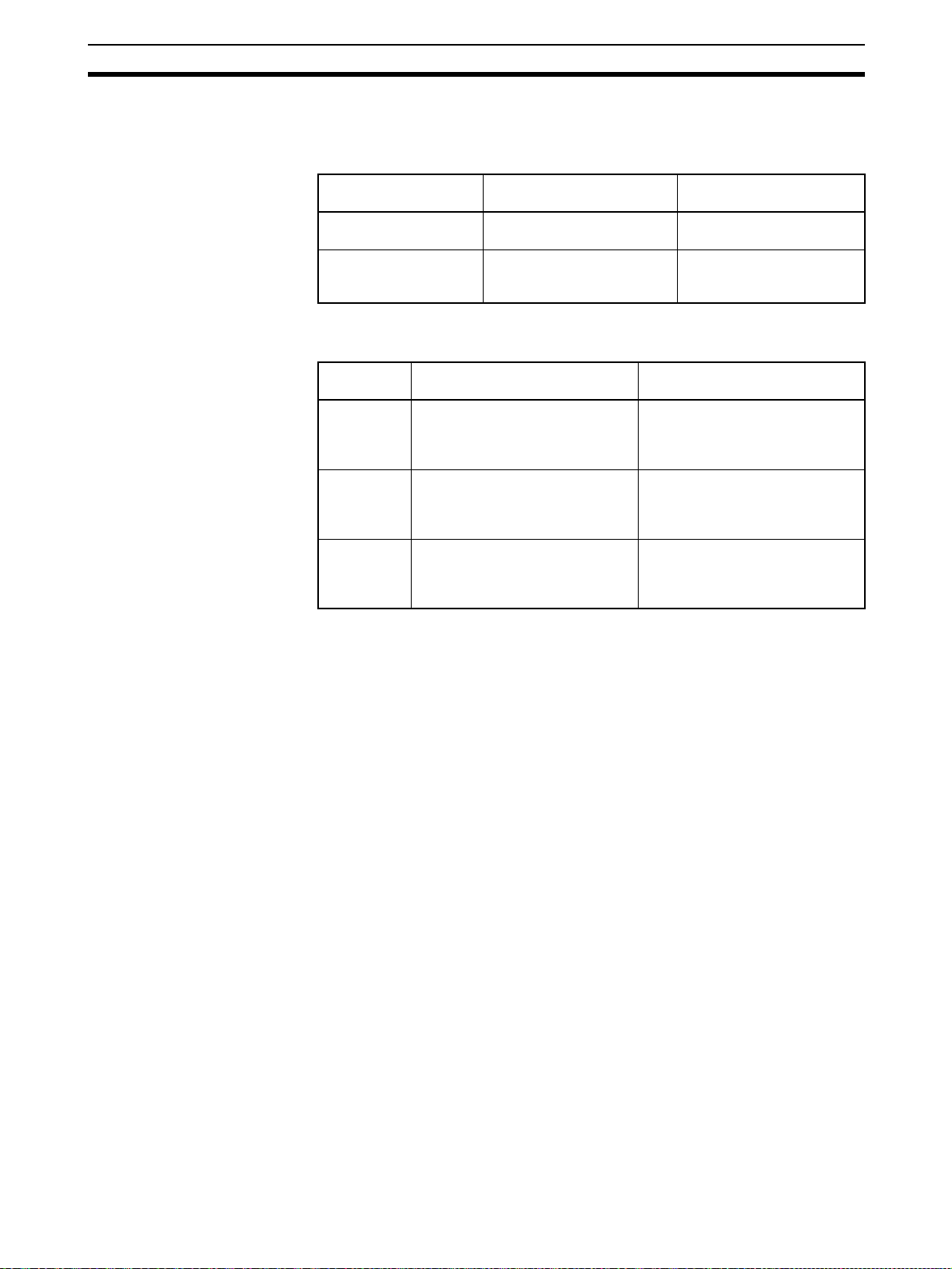
Note Applicable EMC (Electromagnetic Compatibility) standards are listed in the
following table.
Unit EMS (Electromagnetic
C200HW-SRM21-V1 EN61131-2 EN61000-6-4 (See note 2.)
CS1W-SRM21 EN61131-2
CJ1W-SRM21 EN61000-6-2 (See note 1.)
CQM1-SRM21-V1 EN61131-2
SRM1-C0@-V2 EN61000-6-2 (See note 1.)
CPM2C-S@@@C(-DRT) EN61131-2
SRT1 and SRT2 Series EN61000-6-2 (See note 1.)
Note 1. These products have configurations with less than 30 m of I/O wiring, and
less than 10 m of power supply wiring.
2. Radiated emission for EN61000-6-4: 10-m regulations
6-3 Conformance to EC Directives
Observe the follow precautions when installing the CompoBus/S Units that
conform to the EC Directives.
1,2,3... 1. Since the CompoBus/S Units are classified as built-in types, be sure to in-
stall the Units inside a control panel.
2. Provide reinforced insulation or double insulation for the DC Power Supplies that are used as power sources for the alarm output, communications
circuits, and I/O circuits.
Susceptibility)
EMI (Electromagnetic
Interference)
3. The CompoBus/S Units that conform to the EC Directives also conforms
to the Common Emission Standard (EN61000-6-4). When incorporated
into a device, however, the requirements may vary depending on the configuration of the control panel to be used, relationship with other devices to
be connected, wiring, etc. Users are therefore requested to confirm Unit
conformance to the EC Directives by themselves.
xxi
Page 21

Page 22

SECTION 1
System Design
This section provides an overview of the CompoBus/S System and functions, and describes the various Masters, Slaves,
and connection devices that are used to configure a CompoBus/S System.
1-1 System Overview and Features . . . . . . . . . . . . . . . . . . . . . . . . . . . . . . . . . . . . 2
1-1-1 System Overview . . . . . . . . . . . . . . . . . . . . . . . . . . . . . . . . . . . . . . . 2
1-1-2 Network Features . . . . . . . . . . . . . . . . . . . . . . . . . . . . . . . . . . . . . . . 3
1-1-3 Communications Modes . . . . . . . . . . . . . . . . . . . . . . . . . . . . . . . . . . 5
1-2 CompoBus/S System Configuration . . . . . . . . . . . . . . . . . . . . . . . . . . . . . . . . 6
1-2-1 Basic System Configuration . . . . . . . . . . . . . . . . . . . . . . . . . . . . . . . 6
1-2-2 CompoBus/S System Components. . . . . . . . . . . . . . . . . . . . . . . . . . 8
1-3 Compatible Devices . . . . . . . . . . . . . . . . . . . . . . . . . . . . . . . . . . . . . . . . . . . . 10
1-3-1 Compatible Masters . . . . . . . . . . . . . . . . . . . . . . . . . . . . . . . . . . . . . 10
1-3-2 Slave Units . . . . . . . . . . . . . . . . . . . . . . . . . . . . . . . . . . . . . . . . . . . . 13
1-3-3 Cables . . . . . . . . . . . . . . . . . . . . . . . . . . . . . . . . . . . . . . . . . . . . . . . . 16
1-3-4 Connectors/Terminal Blocks . . . . . . . . . . . . . . . . . . . . . . . . . . . . . . 17
1-4 Startup Procedure . . . . . . . . . . . . . . . . . . . . . . . . . . . . . . . . . . . . . . . . . . . . . . 20
1
Page 23
System Overview and Features Section 1-1
1-1 System Overview and Features
1-1-1 System Overview
The CompoBus/S System is a remote I/O communications system with
reduced wiring that retains the functionality and ease of use of the original
remote I/O system (wired type), while providing higher-speed, longer-distance, and highly reliable communications.
The CompoBus/S System allows connection of up to 32 I/O devices (Slaves)
to a Master Unit using only two signal wires, even on long production lines that
require multiple I/O control.
Connect up to 32 Slaves
(256 Points) for Each
Master Unit
CompoBus/S Master Unit
SYSMAC CS Series, C200HX/HG/HE-(Z)E,
C200HS, CJ Series, CQM1/CQM1H
(SRM1, CPM2C-S)
Slaves
Each CompoBus/S Master Unit can be connected to up to 32 Slaves of various types, including I/O Terminals and Sensor Terminals, and allows I/O communications for up to 256 points (128 inputs, 128 outputs).
Main line length: 500 m max.
Terminator
Up to 32 Slaves of various types
Flexible Wiring Configuration
CompoBus/S Master Unit
SYSMAC CS Series, C200HX/HG/
HE-(Z)E, C200HS, CJ Series, CQM1/
CQM1H (SRM1, CPM2C-S)
Total length: 200 m max.
Terminator
I/O Data Exchange without
Special Programming
2
Up to 32 Slaves of various types
I/O data can be exchanged between the Master and Slaves without requiring
any special ladder programming for communications. I/O information for each
Slave is exchanged between Slaves and the corresponding I/O Area in the
Master by simply setting the node number of each Slave.
Page 24
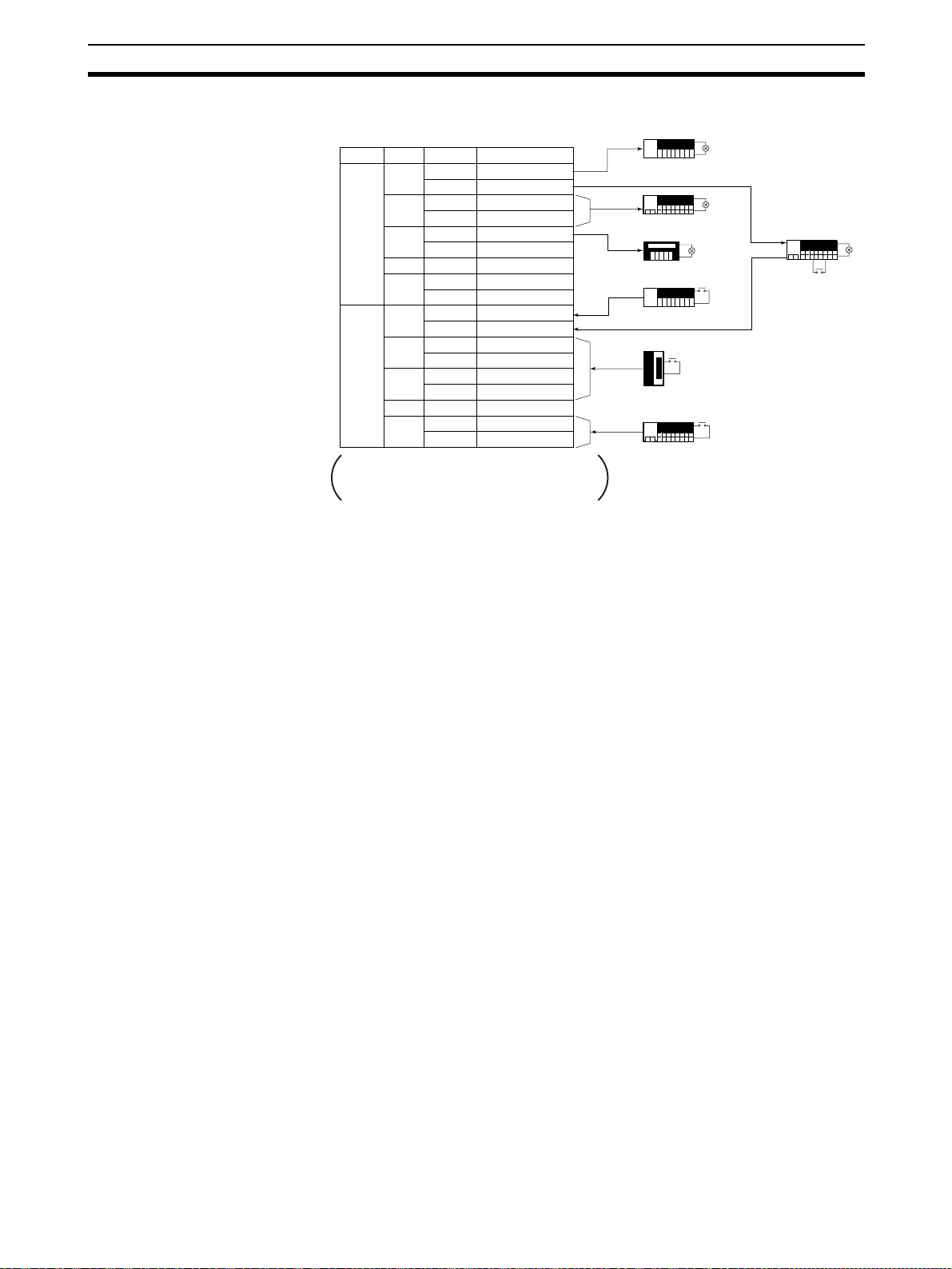
System Overview and Features Section 1-1
Input Slave
CPU Unit's I/O Area
to
to
Node number
00
01
02
03
04
05
to
14
15
00
01
02
03
04
05
to
14
15
Word Bit
00 to 07
CIO
2000
08 to 15
00 to 07
CIO
2001
CIO
2002
to
CIO
2007
CIO
2008
CIO
2009
CIO
2010
to
CIO
2015
08 to 15
00 to 07
08 to 15
00 to 07
08 to 15
00 to 07
08 to 15
00 to 07
08 to 15
00 to 07
08 to 15
00 to 07
08 to 15
OUT
data
IN
data
Example settings using CJ1W-SRM21 Master
Unit with unit #00, connected to 32 Slaves.
Output
OUT node 0
8-point Output Slave
OUT node 2
16-point Output Slave
OUT node 4
8-point Output Slave
Input
IN node 0
8-point Input Slave
IN node 2
32-point Input Slave
IN node 14
16-point Input Slave
IN/OUT node1
8-point Input/
8-point Output
Slave
1-1-2 Network Features
The CompoBus/S has the following features.
Communications Modes Select either a High-speed Communications Mode or Long-distance Commu-
nications Mode for the CompoBus/S according to the system configuration.
The differences between the High-speed Communications Mode and the
Long-distance Communications Mode are described in 1-1-3 Communica-
tions Modes.
Flexible Wiring Up to
200 m
Long-distance
Communications Up to
500 m
High-speed
Communications
Water-resistance Slaves Water-resistant Terminals (IP67) can be used as Slaves to exchange I/O in
In Long-distance Communications Mode, flexible wiring is possible up to a
total cable length of 200 m with no restrictions on branching or node connections, provided that 4-conductor VCTF cable or Special Flat Cable is used.
In Long-distance Communications Mode, communications over the main line
of up to 500 m are possible to control I/O devices in a wide area, provided that
2-conductor VCTF cable is used. In this case, however, each branch line can
be connected to a single Slave only, because the branch line cannot be further branched. Furthermore, the Master must be connected to either end of
the main line.
In High-speed Communications Mode, up to 16 Slaves with 128 I/O points
can be connected with a high-speed communications cycle time of only
0.5 ms. This cycle is fast enough for time-critical factory automation applications.
places exposed to water. Water-resistant Terminals are, however, available
only when the communications cable is 4-conductor VCTF cable.
Reduced Wiring A Slave can be connected to a Master or another Slave with just one connect-
ing cable. If the 4-wire Special Flat Cable or 4-conductor VCTF cable is used,
the Slave’s communication power supply is also supplied through the cable,
so floor wiring can be reduced dramatically. Also, special connectors simplify
branching from a main cable.
3
Page 25

System Overview and Features Section 1-1
Connecting to 4conductor VCTF Cable
Use Both T-branch and
Multidrop Methods
Wide Variety of Masters Master Units are available as Special I/O Units for the CS-series,
Wide Variety of Slaves Units in a wide range are available as I/O Slaves for a variety of applications.
Easy Startup The CompoBus/S System can be started just by wiring the cables and making
Easy-to-obtain 4-conductor VCTF cable can be used instead of the Special
Flat Cable. Furthermore improvement in the environmental resistance of the
system is possible by using shielded connectors.
Both the T-branch and multidrop methods can be combined flexibly when wiring. In combination with the floor cables, this wiring feature allows a very flexible system configuration. There are three types of cables (2-conductor VCTF
cable, 4-conductor VCTF cable, and Special Flat Cable), and when the Special Flat Cable is used, T-branch Connectors can be installed by simply snapping the connector on.
C200HX/C200HG/C200HE-(Z)E, C200HS, CS-series, CJ-series, and CQM1
PLCs and also available integrated with a CPU for the SRM1 and CPM2C-S.
The variety of Masters provides flexibility in configuring a system to match
your application needs.
Such Units include Remote Terminals and Sensor Terminals, which vary with
the number of I/O points or I/O type, Connector Terminals, which allow easy
wiring, and Water-resistant Terminals, which have a better protective construction. There are many Slaves available with advanced functions, including
Analog I/O Terminals for analog-to-digital or digital-to-analog conversion, and
CPM1A/CPM2A/CPM2C I/O Link Units for sharing data with the host PLC.
some simple settings. Replacement of earlier Remote I/O Systems is also
easy.
Slave Node Number
Provided on Indicators
and in PLC Memory
Slave Monitoring for
Improved Reliability
Troubleshooting is easy because the Slave’s node number is shown on the
Master’s indicators if an error occurs with a Slave. When a CS-series,
C200HX/HG/HE-(Z)E, or C200HS Master Unit is used, error information is
also stored in PLC memory.
When an error occurs with a Slave using a CS-series or CJ-series Master
Unit, the Slave's node number is stored in the DM Area using the Slave registration function.
Reliability of the CS-series and CJ-series Master Units has been further
improved by the addition of the following functions.
Slave Registration Function
Registering Slaves in the Master allows the user to check whether connected
Slaves are joined to the network, and to detect whether Slaves are illegally
joined due to incorrect connection, or missing from the network due to a delay
in startup or malfunction of registered Slaves.
Communications Stop Mode
System malfunctions can be avoided by setting remote I/O communications to
stop when a communications error occurs.
4
Page 26
System Overview and Features Section 1-1
1-1-3 Communications Modes
Both High-speed Communications Mode and the Long-distance Communications Mode are supported by the CompoBus/S.
Item High-speed Communica-
Communications baud
rate
Communications cycle
time
750 kbps 93.75 kbps
0.5 ms or 0.8 ms (depending
on maximum number of I/O
points)
tions Mode
The communications distance and the connection configuration vary with the
communications mode and communications cable.
Cable High-speed Communications
2-conductor
VCTF cable
4-conductor
VCTF cable
Special Flat
Cable
Length of main line: 100 m max.
Length of branch line: 3 m max.
Total length of branch lines:
50 m max.
Length of main line: 30 m max.
Length of branch line: 3 m max.
Total length of branch lines: 30 m
max.
Length of main line: 30 m max.
Length of branch line: 3 m max.
Total length of branch lines:
30 m max.
Mode
Long-distance Communi-
cations Mode
4.0 ms or 6.0 ms (depending on maximum number of
I/O points)
Long-distance Communica-
tions Mode
Length of main line: 500 m max.
Length of branch line: 6 m max.
Total length of branch lines:
120 m max.
Flexible branching, provided that
the total length of cable is a maximum of 200 m.
Flexible branching, provided that
the total length of cable is a maximum of 200 m.
Note The I/O response time may be slower when using Long-distance Communica-
tions Mode compared with High-speed Communications Mode. Refer to
O Response Time Characteristics
.
2-5 I/
5
Page 27

CompoBus/S System Configuration Section 1-2
1-2 CompoBus/S System Configuration
1-2-1 Basic System Configuration
Remote Input
Terminals
Photoelectric Sensors,
Proximity Sensors, or
Limit Switches
Fiber Amplifier
Communications
Units
Master Unit
Photoelectric Sensors, Proximity Sensors, Limit Switches
Fiber
Amplifier
Units
C200HW-SRM21-V1 for CS1,
C200HX/C200HG/C200HE (-ZE), and C200HS
CS1W-SRM21 for CS Series, CJ1W-SRM21 for CJ Series,
CQM1-SRM21-V1 for all CQM1 PLCs
SRM1 Master Control Unit
CPM2C-S Series
Remote Input
Terminals
(3-tier terminal
block)
Remote Output Terminals
Solenoids or
valves
Remote I/O
Module
Remote Output Terminals
(3-tier terminal block)
Solenoids or
valves
Analog Input
Terminal
Remote I/O
Terminals
(3-tier terminal block)
Connector I/O
Terminals
Analog Output
Terminal
CPM2A or
CPM1A
Photoelectric Sensors or
Proximity Sensors with connectors
Sensor Terminals
Terminal-block Terminator
I/O Link Unit for
CPM1A/CPM2A
PCB
Optical Fiber Sensors
1 to 5 V,
4 to 20 mA
Master Characteristics
CS-series, C200HX/HG/HE-(Z)E, C200HS Master Units
• Multiple Masters (up to 16) can be connected to a single PLC.
• Up to 128 or 256 I/O points (DIP switch used to switch setting).
• Communications status stored in CPU Unit's I/O Area.
CS-series Master Units
• Multiple Masters (up to 96) can be connected to a single PLC.
• Up to 128 or 256 I/O points (DIP switch used to switch setting).
• Communications status stored in CPU Unit's I/O Area.
• Uses the Slave registration function to monitor which Slaves are joined to
the network.
• Communications can be stopped when a communications error occurs.
CJ-series Master Units
• Multiple Masters (up to 40) can be connected to a single PLC.
• Up to 128 or 256 I/O points (DIP switch used to switch setting).
• Communications status stored in CPU Unit's I/O Area.
Inverters or valves
6
Page 28

CompoBus/S System Configuration Section 1-2
• Uses the Slave registration function to monitor which Slaves are joined to
the network.
• Communications can be stopped when a communications error occurs.
CQM1 Master Units
• Only one Master can be connected to a single PLC.
• Up to 32, 64, or 128 I/O points (DIP switch used to switch setting).
• Alarm output terminal provided to detect errors.
SRM1 and CPM2C-S Master Units with Built-in CPU Units
• Compact CPU Unit with built-in CompoBus/S communications functions.
• Up to 256 I/O points for CompoBus/S functions.
• Communications status stored in CPU Unit's AR Area.
Slave Characteristics
Remote Terminals
• Input or Output Terminals for general-purpose use.
• 4-point, 8-point, and 16-point Transistor Remote Terminals.
• Remote Terminals with no-contact transistor I/O, connector transistor outputs, or relay contact outputs.
Remote Terminals (3-tier Terminal Blocks)
• Input or Output Terminals for general-purpose use.
• 16 points: 8 inputs and 8 outputs mixed.
• Wiring is simple because common terminals for I/O wiring are located at
each point on the 3-tier terminal block.
Connector Terminals
• All I/O wiring can be done using connectors, reducing the amount of labor
for wiring.
• Mounting brackets allow the direction of mounting to be changed.
Water-resistant Terminals
• Input or output terminals of IP67 construction.
• 4 or 8 inputs or outputs.
• Connecting to communications cable, I/O power supply, and I/O through
shielded connectors.
Remote I/O Modules
• Modular type that allows PCB mounting.
• 16-input model and 16-output model.
• User’s devices can be customized as CompoBus/S Slaves.
Sensor Terminals
• Easily connects to Photoelectric Sensor or Proximity Sensor with XS8
Connectors.
• 8-input/8-output model and 4-input/4-output model.
• Remote teaching and external diagnosis are possible by using output signals of the Sensor Terminal.
Fiber Amplifier Communications Units
• Reduced wiring with ON/OFF output and power supply wiring not
required.
• Connecting a Fiber Amplifier Unit allows connection of up to 14 Optical
Fiber Sensors.
7
Page 29
CompoBus/S System Configuration Section 1-2
• Mobile Console can be connected without the Head (Photoelectric Sensor setting, teaching, and adjustment can be executed on site.)
Analog Input Terminals
• Convert analog inputs to binary data.
• The number of analog input points can be switched between 4 points, 3
points, 2 points, and 1 point using a DIP switch.
• The following input ranges are supported:
0 to 5 V, 1 to 5 V, 0 to 10 V, –10 to 10 V, 0 to 20 mA, 4 to 20 mA
Analog Output Terminals
• Convert binary data to analog outputs.
• The number of analog output points can be switched between 2 points
and 1 point using a DIP switch.
• Supports the following output ranges:
1 to 5 V, 0 to 10 V, –10 to 10 V, 0 to 20 mA, 4 to 20 mA
I/O Link Terminals for CPM1A/CPM2A
• Create I/O Links (8 inputs, 8 outputs) with CPM1A and CPM2A PLCs.
CPM2C I/O Link Unit
• Creating I/O Links (8 inputs, 8 outputs) with CPM2C-series PLCs.
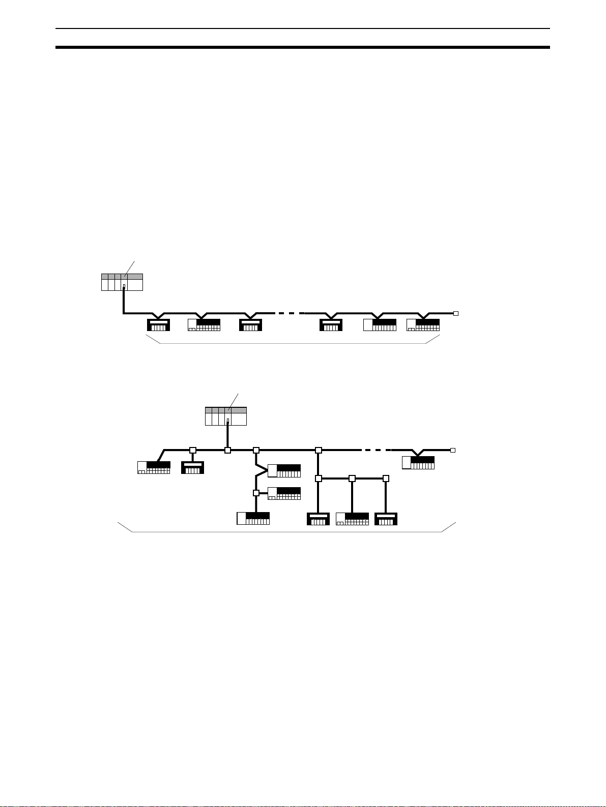
1-2-2 CompoBus/S System Components
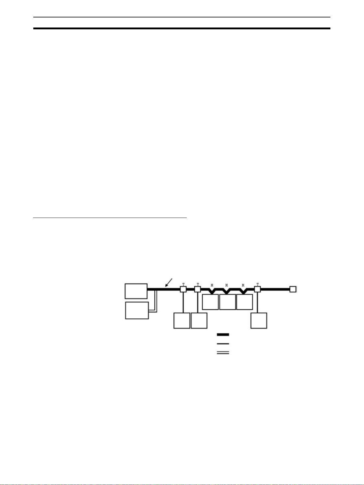
System with Distinct Main and Branch Lines
The diagram below shows a CompoBus/S System in which the main line must
be distinguished from the branch lines under either of the following conditions.
• The system operates in High-speed Communications Mode.
• The system operates in Long-distance Communications Mode with 2-conductor VCTF cable. (The maximum length of the main line varies with the
type of communications cable.)
Communications Cable
Te r mi n a to r
Master
Communications Power
Supply
Slave Slave
Master The Master administers the CompoBus/S System and manages the external
I/O of the Slaves. There is only 1 Master in a CompoBus/S System and the
Master must be connected at the end of the main line, as shown in the preceding diagram.
Slave Slave Slave
Main line
Branch line
Power supply cable
Slave
T: T-branch connection
M: Multidrop connection
Slaves The external I/O connected to the Slaves is processed by communicating with
the Master through the CompoBus/S System.
Main/Branch Lines The main line is the main cable that connects the two most distant points of
the system. Cables branching from the main line are known as branch lines.
Cables CompoBus/S communications are transmitted through 2-conductor VCTF, 4-
conductor VCTF, or Special Flat Cable. When 4-conductor VCTF or Special
8
Page 30
CompoBus/S System Configuration Section 1-2
Flat Cable is used, the communications power supply can be supplied through
the cable. The system shown in the preceding diagram uses 4-conductor
VCTF or Special Flat Cable. When 2-conductor VCTF cable is used, power
must be supplied to the Slaves through a separate cable.
Connection Methods Two methods can be used to connect CompoBus/S Slaves: the T-branch
method and the multidrop method. With the T-branch method, the Slave is
connected to a branch line which branches off from the main line. With the
multidrop method, the Slave is connected directly to the main line.
These two connection methods can both be used in the same system,
although it is not possible to make a secondary branch from a branch line.
Use OMRON’s Branch Connector, a T-joint for a shielded connector, or a commercially available terminal block to create a branch from the main line.
Termina tor A terminator must be connected to the end of the main line opposite the Mas-
ter in order to stabilize communications. There are three kinds of terminating
resistors available, a connector for use with Special Flat Cable, a terminal
block, and a shielded connector.
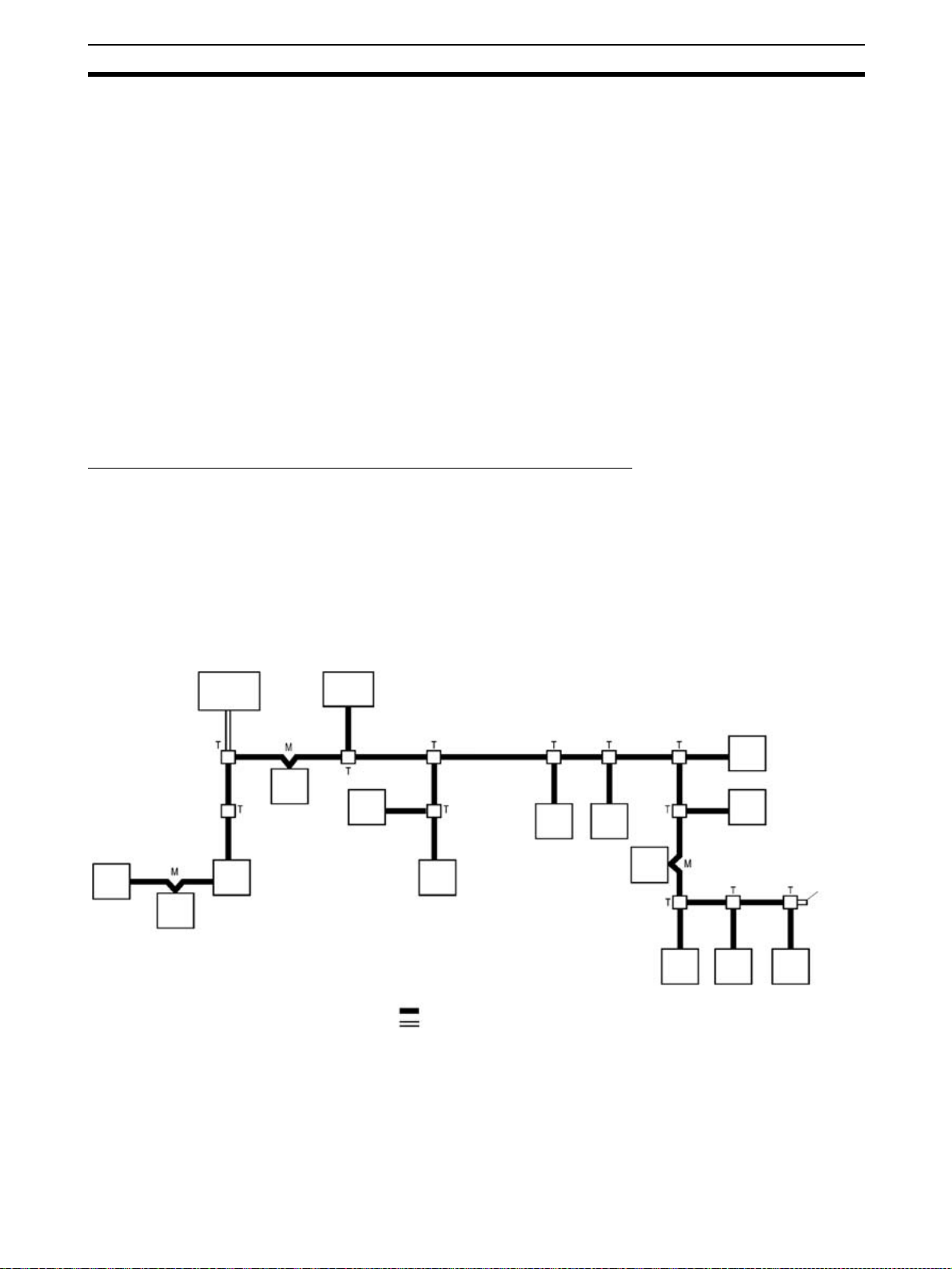
System with No Distinction between Main and Branch Lines
The diagram below shows a CompoBus/S System in which it is not necessary
to distinguish between the main line and branch lines. This applies to the following conditions.
• The system operates in Long-distance Communications Mode with 4-conductor VCTF cable.
• The system operates in Long-distance Communications Mode with Special Flat Cable.
(The maximum length of cable is 200 m regardless of the type of communications cable.)
Slave
Slave
Communications Power
Supply
Slave
Slave
Master
Slave
Slave
Communications cable
Power supply cable
Slave
Slave
Slave
Slave
Slave
Terminator
Slave Slave Slave
T: T-branch connection
M: Multidrop connection
Master The Master administers the CompoBus/S System and manages the external
I/O of the Slaves. There is only one Master in a CompoBus/S System and the
Master can be connected anywhere.
Slaves The external I/O connected to the Slaves is processed by communicating with
the Master through the CompoBus/S System.
9
Page 31

Compatible Devices Section 1-3
Cables CompoBus/S communications are transmitted through Special Flat Cable or
4-conductor VCTF cable. The communications power supply can be supplied
through either of the cables.
Connection Methods Two methods can be used to connect the CompoBus/S Master and Slaves:
the T-branch method and the multidrop method. With the T-branch method,
the Slave is connected to a line that branches off from the communications
cable wherever desired. With the multidrop method, the Master or Slave is
connected directly to the communications cable. These two connection methods can both be used in the same system and it is possible to make a secondary branch from a branch line. Use OMRON’s Branch Connector for Special
Flat Cable, a T-joint for a shielded connector, or a commercially available terminal block to create a branch from the communications cable.
Termina tor A terminator must be connected to the end of the communications cable far-
thest from the Master in order to stabilize communications. There are three
kinds of terminating resistors available, a connector for use with Special Flat
Cable, a terminal block, and a shielded connector. In a system in which distinguishing between the main and branch lines is not necessary, only a single
terminator farthest from the Master is required regardless of the position the
Master is connected to the communications cable.
1-3 Compatible Devices
1-3-1 Compatible Masters
Masters with
Communications
Functions
PLC C200HX-CPU3@-
Master
Unit
Communications
mode
Analog I/O
Te r mi n al
connection
Max. number of Masters
Master
Unit
mounting
location
(Z)E/ CPU4@-(Z)E,
C200HG-CPU3@-
(Z)E/CPU4@-(Z)E,
C200HE, C200HS
C200HW-SRM21-V1 CS1W-SRM21 CJ1W-SRM21 CQM1-SRM21-V1
High-speed Communications Mode or Long-distance Communications Mode (switched using the DIP switch
on front panel)
Possible
10 Units (when
using a single Special I/O Unit node
number (i.e., 10
words))
5 Units (when using
two Special I/O Unit
node number (i.e.,
20 words))
Can be mounted on the CPU Backplane or Expansion I/O Backplane. Can’t be mounted on a SYSMAC BUS Slave (RT) Rack.
There are three types of Master Units which can be used in CompoBus/S
Systems. The model of the Master Unit which must be used depends on the
PLC being used.
C200HX-CPU5@-
(Z)E/ CPU6@-(Z)E/
CPU8@-(Z)E,
C200HG-CPU5@-
(Z)E/ CPU6@-(Z)E,
CS Series
16 Units (when
using a single Special I/O Unit node
number (i.e., 10
words))
8 Units (when using
two Special I/O Unit
node number (i.e.,
20 words))
CS Series CJ Series CQM1, CQM1H
96 Units (when
using a single Special I/O Unit node
number (i.e., 10
words))
95 Units (when
using two Special
I/O Unit node number (i.e., 20 words))
40 Units CQM1: 1 Unit
CQM1H: Up to the
number corresponding to the maximum
I/O points for the
CPU Unit.
Can be connected
in the CPU Rack or
Expansion Rack.
No restrictions.
10
Page 32

Compatible Devices Section 1-3
PLC C200HX-CPU3@-
Max. number of I/O
points per
Master
Number of
points per
node number
Number of
usable
node numbers per
Master
Master
Unit power
supply
(Z)E/ CPU4@-(Z)E,
C200HG-CPU3@-
(Z)E/CPU4@-(Z)E,
C200HE, C200HS
256 points (128 inputs/128 outputs) or 128 points (64 inputs/64 outputs)
The max. number of I/O points depends on the DIP switch settings.
The area allocated to Special I/O Units is used for I/O.
8-point mode 8-point mode 8-point mode or 4-
IN0 to IN7 and OUT0 to OUT7 or IN0 to
IN15 and OUT0 to OUT15
Not required. (Power is supplied from the
PLC.)
C200HX-CPU5@-
(Z)E/ CPU6@-(Z)E/
CPU8@-(Z)E,
C200HG-CPU5@-
(Z)E/ CPU6@-(Z)E,
CS Series
CS Series CJ Series CQM1, CQM1H
CQM1-CPU11-E/
21-E:
32 points (16 inputs/
16 outputs) or
64 points (32 inputs/
32 outputs)
CQM1-CPU41-EV1/
42-EV1/
43-EV1/44-EV1:
32 points (16
inputs/16 outputs)
or
64 points (32
inputs/32 outputs)
or
128 points
(64 inputs/
64 outputs)
The max. number of
I/O points depends
on the DIP switch
settings.
The IR area is used
for I/O.
point mode
IN0 to IN7 and OUT0 to OUT7 or IN0 to
IN15 and OUT0 to OUT15
Not required. (Power is supplied from the
PLC.)
When 8 points are
used per node:
IN0 to IN1/OUT0
to OUT1 or
IN0 to IN3/OUT0
to OUT3 or
IN0 to IN7/OUT0
to OUT7
When 4 points are
used per node:
IN0 to IN3/OUT0
to OUT3 or
IN0 to IN7/OUT0
to OUT7 or
IN0 to IN15/OUT0
to OUT15
Not required.
(Power is supplied
from the PLC.)
11
Page 33

Compatible Devices Section 1-3
PLC C200HX-CPU3@-
Te r mi n al
for connecting
communications
power supply for
Slaves
Status indicators
(Z)E/ CPU4@-(Z)E,
C200HG-CPU3@-
(Z)E/CPU4@-(Z)E,
C200HE, C200HS
Not provided Provided Not provided
The PLC’s AR Area contains the active
node flags and communications error flags
for each Slave.
C200HX-CPU5@-
(Z)E/ CPU6@-(Z)E/
CPU8@-(Z)E,
C200HG-CPU5@-
(Z)E/ CPU6@-(Z)E,
CS Series
CS Series CJ Series CQM1, CQM1H
The PLC’s Auxiliary Area contains the
active node flags and communications
error flags for each Slave. The DM Area
contains an area for Slave registration and
setting communications stop mode.
There is an alarm
output terminal in
the terminal block.
Note 1. Previous Master Unit models (without -V1), which do not support the Long-
distance Communications Mode, cannot be used when an Analog I/O Terminal is connected as a Slave. If used, incorrect data may be transmitted.
2. Refer to
SECTION 4 Master Unit Specifications and Operations for more
details on the Master Units.
Master with Built-in CPU The following Master Control Unit models, which have a built-in CPU Unit, are
used for distributed I/O control in CompoBus/S Systems. Refer to the SRM1
Master Control Unit Operation Manual (W318-E1-@) and the CPM2C-S PLC
Operation Manual (W377-E1-@) for details.
SRM1 Master Control Unit
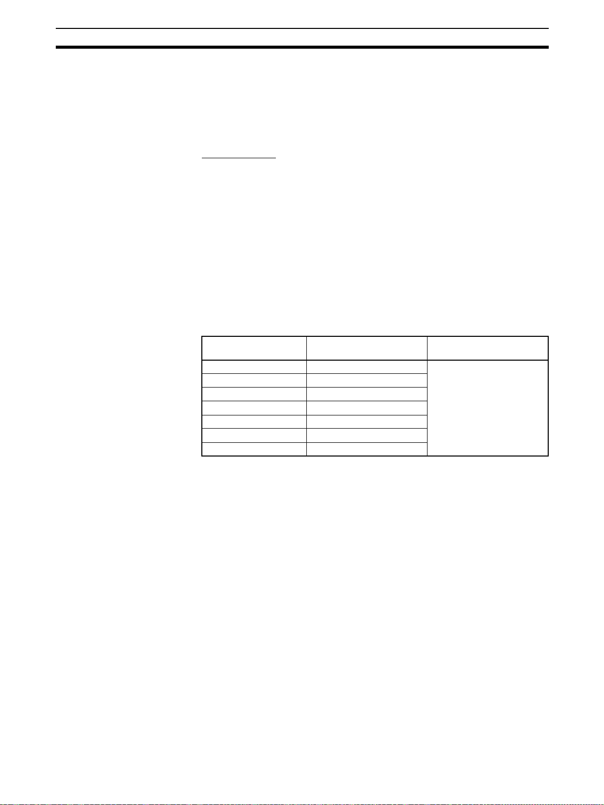
Item Master Control Unit
SRM1-CPU01-V2 SRM1-CPU02-V2
Peripheral port Yes Yes
RS-232C port --- Yes
Program capacity 4K words
Max. number of I/O points 256 (128 inputs/128 outputs)
Communications mode High-speed Communications Mode or Long-distance
Number of points per node
number
Number of usable node
numbers per Master
Status indicators The PLC’s AR Area contains the active node flags and
Communications Mode (switched using PLC Setup)
8-point mode
IN0 to IN7 and OUT0 to OUT7 or IN0 to IN15 and
OUT0 to OUT15
communications error flags for each Slave.
CPM2C-S PLC
The CPM2C-S PLC has built-in CompoBus/S Master and DeviceNet Slave
functions. Models that support I/O links with host PLCs are available as well.
Item Master Control Unit
CPM2C-S@@@CCPM2C-S@@@C-DRT
Peripheral port The same connector is used.
RS-232C port
Program capacity 4K words
Max. number of I/O points 256 (128 inputs/128 outputs)
Communications mode High-speed Communications Mode or Long-distance
Communications Mode (switched using PLC Setup)
12
Page 34

Compatible Devices Section 1-3
Item Master Control Unit
CPM2C-S@@@CCPM2C-S@@@C-DRT
Number of points per node
number
Number of usable node
numbers per Master
Status indicators The PLC’s AR Area contains the active node flags and
DeviceNet Slave function Not provided Provided
8-point mode
IN0 to IN7 and OUT0 to OUT7 or IN0 to IN15 and OUT0
to OUT15
communications error flags for each Slave.
Master Units and
Corresponding
Communications Modes
Master Units support only High-speed Communications Mode or both Highspeed Communications Mode and Long-distance Communications Mode.
Slave Analog Terminals can be connected to the Units that support both Highspeed and Long-distance Communications Modes. These Units are an
upgraded version and, by switching the communications mode, can be used
instead of the Units that support only the High-speed Communications Mode.
Item Unit supporting
Communications modes
Analog I/O Terminal connections No Yes
High-speed Communications Mode
Long-distance Communications Mode
High-speed Communications only
Ye s Y e s
No Yes
Unit supporting
High-speed and
Long-distance
Communications
The following models are available.
PLC Units supporting
CS-series, C200HX/C200HG/
C200HE-(Z)E, and C200HS
Master Units
CS-series Master Units --- CS1W-SRM21
CJ-series Master Units --- CJ1W-SRM21
CQM1 Master Units CQM1-SRM21 CQM1-SRM21-V1
SRM1 SRM1-C0@
CPM2C-S --- CPM2C-S@@@ (-DRT)
High-speed Com-
munications
C200HW-SRM21 C200HW-SRM21-V1
SRM1-C0@-V1
Units supporting High-
speed and Long-distance
Communications
SRM1-C0@-V2
Note Master Units that do not support Long-distance Communications Mode can-
1-3-2 Slave Units
not be used when connecting an Analog Terminal as a Slave. If used, incorrect data may be transmitted.
The SRT1/SRT2 Series provides Slaves that support only High-speed Communications Mode or both High-speed Communications Mode and Long-distance Communications Mode. The SRT2-series Slaves that support Highspeed and Long-distance Communications Modes are an upgraded version
13
Page 35

Compatible Devices Section 1-3
and, by switching the communications mode, can be used instead of the
Slaves that support only the High-speed Communications Mode.
Item Slaves supporting
Slave Series SRT1 Series SRT2 Series
Communica-
tions modes
High-speed Communications Mode
Long-distance Communications Mode
High-speed Com-
munications
Ye s Y e s
No Yes
Available models are shown in the following table.
Type Previous models New models I/O points Power supply
Slave SRT1 Series SRT2 Series
Remote Terminals
with Transistors
SRT1-ID04 SRT2-ID04 4 inputs (NPN) Multiple supSRT1-ID04-1 SRT2-ID04-1 4 inputs (PNP)
SRT1-ID08 SRT2-ID08 8 inputs (NPN)
SRT1-ID08-1 SRT2-ID08-1 8 inputs (PNP)
SRT1-ID16 SRT2-ID16 16 inputs (NPN)
SRT1-ID16-1 SRT2-ID16-1 16 inputs (PNP)
SRT1-ID16T SRT2-ID16T 16 inputs
(NPN, 3-tier terminal block)
SRT1-ID16T-1 SRT2-ID16T-1 16 inputs
(PNP, 3-tier terminal block)
SRT1-OD04 SRT2-OD04 4 outputs (NPN)
SRT1-OD04-1 SRT2-OD04-1 4 outputs (PNP)
SRT1-OD08 SRT2-OD08 8 outputs (NPN)
SRT1-OD08-1 SRT2-OD08-1 8 outputs (PNP)
SRT1-OD16 SRT2-OD16 16 outputs (NPN)
SRT1-OD16-1 SRT2-OD16-1 16 outputs (PNP)
SRT1-OD16T SRT2-OD16T 16 outputs
(NPN, 3-tier terminal block)
SRT1-OD16T-1 SRT2-OD16T-1 16 outputs
(PNP, 3-tier terminal block)
SRT1-MD16T SRT2-MD16T 8 inputs, 8 outputs
(NPN, 3-tier terminal block)
SRT1-MD16T-1 SRT2-MD16T-1 8 inputs, 8 outputs
(PNP, 3-tier terminal block)
Slaves supporting
High-speed and
Long-distance
Communications
plies
14
Page 36

Compatible Devices Section 1-3
Type Previous models New models I/O points Power supply
Slave SRT1 Series SRT2 Series
Connector Terminals (8-point/16point Transistors)
Connector Terminals (32-point Transistors)
Remote Terminals
with Relays
Remote Terminals
with Power MOS
FETs
Water-resistant Terminals (Transistors)
Sensor Terminals SRT1-ID08S SRT2-ID08S 8 inputs Network
Remote I/O Modules
None SRT2-VID08S 8 inputs
(NPN, sensor connectors)
SRT2-VID08S-1 8 inputs
(PNP, sensor connectors)
SRT2-VID16ML 16 inputs
(NPN, MIL connectors)
SRT2-VID16ML-1 16 inputs
(PNP, MIL connectors)
SRT2-VOD08S 8 outputs
(NPN, sensor connectors)
SRT2-VOD08S-1 8 outputs
(PNP, sensor connectors)
SRT2-VOD16ML 16 outputs
(NPN, MIL connectors)
SRT2-VOD16ML-1 16 outputs
(PNP, MIL connectors)
None SRT2-ID32ML 32 inputs
(NPN, MIL connectors)
SRT2-ID32ML-1 32 inputs
(PNP, MIL connectors)
SRT2-OD32ML 32 outputs
(NPN, MIL connectors)
SRT2-OD32ML-1 32 outputs
(PNP, MIL connectors)
SRT2-MD32ML 16 inputs, 16 outputs
(NPN, MIL connectors)
SRT2-MD32ML-1 16 inputs, 16 outputs
(PNP, MIL connectors)
SRT1-ROC08 SRT2-ROC08 8 outputs Local
SRT1-ROC16 SRT2-ROC16 16 outputs
SRT1-ROF08 SRT2-ROF08 8 outputs
SRT1-ROF16 SRT2-ROF16 16 outputs
None SRT2-ID04CL 4 inputs (NPN) Multiple sup-
SRT2-ID04CL-1 4 inputs (PNP)
SRT2-ID08CL 8 inputs (NPN)
SRT2-ID08CL-1 8 inputs (PNP)
SRT2-OD04CL 4 outputs (NPN)
SRT2-OD04CL-1 4 outputs (PNP)
SRT2-OD08CL 8 outputs (NPN)
SRT2-OD08CL-1 8 outputs (PNP)
SRT1-ND08S SRT2-ND08S 4 inputs, 4 outputs
SRT1-OD08S SRT2-OD08S 8 outputs
(NPN, connector outputs)
SRT1-ID16P SRT2-ID16P 16 inputs (NPN, PCB attachment) --SRT1-OD16P SRT2-OD16P 16 outputs (NPN, PCB attach-
ment)
Multiple supplies
plies
Local
15
Page 37

Compatible Devices Section 1-3
Type Previous models New models I/O points Power supply
Slave SRT1 Series SRT2 Series
Fiber Amplifier
Communications
Unit
Analog Input Terminals
Analog Output Terminals
I/O Link Units None CPM1A-SRT21 8 inputs, 8 outputs
CPM2C I/O Link
Units
Network Power Supply These Slaves use a single power supply and can be supplied with power from
None E3X-SRT21 8-point input or 16 point input (with
Fiber Amplifier Unit connected)
None SRT2-AD04 Switchable between 4-point, 3-
point, 2-point, and 1-point analog
input
None SRT2-DA02 Switchable between 2-point and 1-
point analog output
(For CPM1A/CPM2A)
None CPM2C-SRT21 8 inputs, 8 outputs (For CPM2C) ---
Network
---
Note 1. The power supply requirements are described below. Refer to 2-3 Supply-
ing Power to the Slaves
for details on these power supplies.
2. Refer to SECTION 5 Slave Specifications and Operations for details on
Slaves.
the Special Flat Cable for CompoBus/S.
Multiple Power Supplies These Slaves require two separate power supplies for communications and I/
O.
The communications power can be supplied from the Special Flat Cable for
CompoBus/S.
Local Power Supply These Slaves require a single external power supply. The power cannot be
supplied from the Special Flat Cable for CompoBus/S.
1-3-3 Cables
Cables The following table lists the cables that can be used in a CompoBus/S Sys-
tem.
Cable Specifications
2-conductor VCTF cable
(sold commercially)
4-conductor VCTF cable
(sold commercially)
Special Flat Cable
(OMRON SCA1-4F10,
100 m)
Vinyl-clad VCTF JIS C 3306
Two 0.75 mm
Resistance: 25.1 Ω/km at 20°C
Use only 2-conductor VCTF cable.
Vinyl-clad VCTF JIS C 3306
Four 0.75 mm
supply wires)
Resistance: 25.1 Ω/km at 20°C.
Four 0.75 mm
(2 signal wires and 2 power supply wires)
Maximum ambient temperature: 60°C
2
conductors (2 signal wires)
2
conductors (2 signal wires and 2 power
2
conductors
16
Note 1. Do not use cables other than those specified above.
2. For information on communications cables specified by overseas manufacturers, refer to
Appendix Standard Models.
Page 38

Compatible Devices Section 1-3
The communications distance depends on the cable used, as follows:
Cable Mode Main line
2-conductor VCTF
cable
4-conductor VCTF
cable
Special Flat Cable High-speed Commu-
High-speed Communications Mode
Long-distance Communications Mode
High-speed Communications Mode
Long-distance Communications Mode
nications Mode
Long-distance Com-
munications Mode
length
100 m max. 3 m max. 50 m max.
500 m max. 6 m max. 120 m max.
30 m max.
(See note.)
Flexibly branched, provided that the
total length of cable is a maximum of
200 m.
30 m max.
(See note.)
Flexibly branched, provided that the
total length of cable is a maximum of
200 m.
Note When 4-conductor VCTF cable or Special Flat Cable is used to connect fewer
than 16 Slaves, the main line can be up to 100 m long and the total branch
line length can be up to 50 m in High-speed Communications Mode. (These
are the same conditions as when 2-conductor VCTF cable is used.)
Branch
line length
3 m max.
(See note.)
3 m max.
(See note.)
Tot al
branch
line length
30 m max.
(See note.)
30 m max.
(See note.)
1-3-4 Connectors/Terminal Blocks
The following table lists the connectors that can be used in a CompoBus/S
System.
Connector Model Comments
Branch Connector SCN1-TH4 Use this connector to create a branch line
Extension Connector SCN1-TH4E Use this connector to extend the Special Flat
Connector Terminator SCN1-TH4T This connector has a built-in terminator.
Connectors with Cable with a
socket and plug
Connector with Cable with a
female socket
Connector with Cable with a
male plug
XS2W-D42@-@81-@ Connectors with cable used to connect the
XS2F-D42@-@80-@ A connector with cable used to connect the
XS2H-D421-@80-A A connector with a cable used to connect the
from the main line.
(Used with Special Flat Cable only.)
Cable.
(Used with Special Flat Cable only.)
Water-resistant Terminal to a T-joint.
Can be used as a power supply cable (with
the female socket connected to the Waterresistant Terminal).
Can be used as an I/O cable for sensors that
have connectors (with the male plug connected to the Water-resistant Terminal, if the
product has a model number suffix “A”).
Water-resistant Terminal to a T-branch connector.
Can be used as a power supply cable (with
the female socket connected to the Waterresistant Terminal) and the other end wired to
a commercially available terminal block.
Water-resistant Terminal to an I/O device.
Can be used as an I/O cable (with the male
plug connected to the Water-resistant Terminal) and the other end wired to the I/O device.
17
Page 39

Compatible Devices Section 1-3
Connector Model Comments
Connector Socket Assembly
(female for screw, crimp, solder terminals)
Connector Plug Assembly
(male for screw, crimp, solder
terminals)
T-joint XS2R-D427-5 A joint used to T-branch a VCTF cable (e.g., a
Communications Connector
(6 pins)
Shielded Terminator Plug
(Male)
Terminal-block Terminator SRS1-T This terminal block has a built-in terminator.
XS2C-D4S7 A connector used to connect to the communi-
XS2C-D4@@ A connector used to connect to the external
XS2G-D4S7 A connector used to connect to the T-joint
XS2G-D4@@ A connector used to connect to the I/O con-
FK-MCP1.5/6-STF-
3.81
MC1.5/6-STF-3.81 A communications connector for connecting
SRS2-1 A shielded connector terminator model con-
cations connector or external power supply
connector of the Water-resistant Terminal or a
T- j oi n t p l ug .
Applicable cable dia.: 6 to 8 mm
Applicable conductor size: 0.18 to 0.75 mm
power supply connector of the Water-resistant
Terminal or a T-joint plug.
Applicable cable dia.: 3 to 6 mm
Applicable conductor size: 0.18 to 0.3 or 0.5
to 0.75 mm
socket.
Applicable cable dia.: 6 to 8 mm
Applicable conductor size: 0.18 to 0.75 mm
nector of the Water-resistant Terminal or a Tjoint socket.
Applicable cable dia.: 3 to 6 mm
Applicable conductor size: 0.18 to 0.3 or 0.5
to 0.75 mm
communications cable or power supply
cable).
A communications connector for connecting
CJ-series Master Units. The connector can be
connected simultaneously to the communications cable (BD H, BD L, BS+, BS–) and communications power supply (BS+, BS–).
This connector has screwless terminals for
signal lines and connector lock screws.
CJ-series Master Units. The connector can be
connected simultaneously to the communications cable (BD H, BD L, BS+, BS–) and communications power supply (BS+, BS–).
This connector has screw terminals for signal
lines and connector lock screws.
nected to a T-joint.
(Can be used with VCTF cable and Special
Flat Cable.)
2
2
2
2
18
Note 1. Connect a terminator (Connector Terminator, Shield Terminator, or Termi-
nal-block Terminator) to the following point in the system.
• System with Distinction between Main and Branch Lines: The end of
the main line farthest from the Master.
• System with No Distinction Main and Branch Lines: The end of the
communications cable farthest from the Master.
2. Use a commercially available terminal block or T-joint to branch or extend
VCTF cable.
Page 40

Compatible Devices Section 1-3
Dimensions
The following diagram shows the dimensions (after assembly). All dimensions
are in mm.
SCN1-TH4 Branch Connector
18.5
17
20
SCN1-TH4E Extension Connector
18.5
17
15
15
SCN1-TH4T Connector Terminator
Connectors with Cables
XS2W-D42(-(81-( (socket and plug)
Plug (male) Socket (female)
XS2F-D42(-(80-( (socket on one end) XS2H-D421-(80-A (plug on one end)
20
20
18.5
17
SCN1
1
15
Socket (female)
Plug (male)
19
Page 41

Startup Procedure Section 1-4
Connector Assembly
Socket (Female)
(Crimp terminals/Solder terminals)
XS2C-D4S7 (Communications)
XS2C-D4(( (Power supply and I/O)
XS2R-D427-5 T-joint
Socket (female) Plug (male)
SRS2-1 Shield Terminator Plug (male)
SRS1-T Terminal-block Terminator
Plug (Male)
(Crimp terminals/Solder terminals)
XS2G-D4S7 (Communications)
XS2G-D4(( (Power supply and I/O)
Plug (male)Socket (female)
Socket (female)
Plug (male)
1-4 Startup Procedure
The standard procedure for starting up the CompoBus/S System is as follows:
Selecting Master and
Slave
Select the Master and Slaves according to the following items.
• PLC model being used (Refer to
4 Master Unit Specifications and Operations
• Number of Slaves (Refer to 1-3-1 Compatible Masters)
• Maximum I/O points (Refer to
• Slave I/O types (Refer to
fications and Operations
21
20
40 20
Mounting Holes
Two, 4.2 dia. or M4
30±0.2
1-3-1 Compatible Masters and SECTION
.)
1-3-1 Compatible Masters)
1-3-2 Slave Units and SECTION 5 Slave Speci-
)
Determining the
Communications Mode
Determining System
Configuration
20
Determine the communications mode according to the following items.
• Communications distance (Refer to
• I/O response time (Refer to
2-5 I/O Response Time Characteristics)
2-2-2 Maximum Cable Length)
Determine the CompoBus/S System configuration according to the following
items. Select the devices required for connection (such as connectors, terminal blocks, and terminators) according to the system configuration.
Page 42

Startup Procedure Section 1-4
• Arrangement of Master and Slaves (Refer to page 8 and page 25.)
• Cable types applicable for the communications distance and communications mode (Refer to page 16 and page 29.)
• Connection methods (Refer to page 8 and page 27.)
• Methods for supplying communications and I/O power supplies (Refer to
page 31.)
• Connectors and terminal block models (Refer to page 6 and page 27.)
Setting the Master Unit Set the Master Unit according to the model used, referring to
Master Unit Specifications and Operations
CS-series, C200HX/HG/HE-(Z)E, and C200HS Master Units (C200HWSRM21-V1)
• Special I/O Unit unit number
• Number of nodes that can be connected
• Communications mode
CS-series Master Units (CS1W-SRM21)
• Special I/O Unit unit number
• Number of nodes that can be connected
• Communications mode
• Slave registration function (Set in DM Area while connected to the PLC.)
• Communications stop mode setting function
CJ-series Master Units
• Special I/O Unit unit number
• Number of nodes that can be connected
• Communications mode
• Slave registration function (Set in DM Area while connected to the PLC.)
• Communications stop mode setting function
.
SECTION 4
CQM1 Master Units
• Number of words allocated to the CPU
• Number of bits allocated for each node number
• Communications mode
Setting the Slaves Set the Slave Units, referring to
tions
.
• Node number
• Communications mode
• Settings specific to each Slave (such as output holding/clearing when
communications errors occur)
Wiring Wire and connect the communications cables, communications power supply,
I/O power supply, referring to the device specifications in
Unit Specifications and Operations
Operations
ing
.
Starting and Checking
Operations
Starting Operations Start operating the Master and Slaves.
Start the CompoBus/S System and check the Master and Slave operations,
referring to
, and wiring information in SECTION 3 CompoBus/S System Wir-
SECTION 6 Starting Communications.
SECTION 5 Slave Specifications and Opera-
SECTION 4 Master
, SECTION 5 Slave Specifications and
21
Page 43

Page 44

SECTION 2
CompoBus/S System Specifications and Configuration
This section provides information on CompoBus/S System specifications, methods used to configure a CompoBus/S
System, and I/O response times.
2-1 Communications Specifications . . . . . . . . . . . . . . . . . . . . . . . . . . . . . . . . . . . 24
2-2 System Configuration . . . . . . . . . . . . . . . . . . . . . . . . . . . . . . . . . . . . . . . . . . . 25
2-2-1 Main Line/Branch Line Connections . . . . . . . . . . . . . . . . . . . . . . . . 25
2-2-2 Maximum Cable Length . . . . . . . . . . . . . . . . . . . . . . . . . . . . . . . . . . 29
2-2-3 Terminator Connection . . . . . . . . . . . . . . . . . . . . . . . . . . . . . . . . . . . 31
2-3 Supplying Power to the Slaves . . . . . . . . . . . . . . . . . . . . . . . . . . . . . . . . . . . . 31
2-3-1 Using 2-conductor VCTF Cable. . . . . . . . . . . . . . . . . . . . . . . . . . . . 33
2-3-2 Using 4-conductor VCTF or Special Flat Cable. . . . . . . . . . . . . . . . 34
2-3-3 Limitations of Communications Cable Power Supply . . . . . . . . . . . 35
2-4 System Configuration Using Water-resistant Terminals . . . . . . . . . . . . . . . . . 41
2-5 I/O Response Time Characteristics. . . . . . . . . . . . . . . . . . . . . . . . . . . . . . . . . 41
2-5-1 Slaves Other Than Analog Terminals. . . . . . . . . . . . . . . . . . . . . . . . 42
2-5-2 Slave Analog Terminals . . . . . . . . . . . . . . . . . . . . . . . . . . . . . . . . . . 46
2-5-3 Slave I/O Delay Times . . . . . . . . . . . . . . . . . . . . . . . . . . . . . . . . . . . 51
23
Page 45

Communications Specifications Section 2-1
2-1 Communications Specifications
This section provides specifications for the CompoBus/S System.
Item Specification
Communications method Special CompoBus/S protocol
Communications baud rate High-speed Communications Mode: 750 kbps
Modulation method Baseband method
Coding method Manchester coding method
Error control checks Manchester code check, frame length check, and parity check
Cable VCTF cable
Communications
distance
(JIS C 3306)
Special Flat Cable
2-conductor VCTF
cable
4-conductor VCTF
cable
Special Flat Cable High-speed Communications Mode
Long-distance Communications Mode: 93.75 kbps
2
Two 0.75 mm
Four 0.75 mm
Four 0.75 mm
High-speed Communications Mode
Main line length: 100 m max.
Branch line length: 3 m max.
Total branch line length: 50 m max.
Long-distance Communications Mode
Main line length: 500 m max.
Branch line length: 6 m max.
Total branch line length: 120 m max.
High-speed Communications Mode
Main line length: 30 m max.
Branch line length: 3 m max.
Total branch line length: 30 m max.
Long-distance Communications Mode: Flexibly branched, provided that the
total length of cable is a maximum of 200 m.
Main line length: 30 m max.
Branch line length: 3 m max.
Total branch line length: 30 m max.
When 4-conductor VCTF cable or Special Flat Cable is used to connect fewer
than 16 Slaves, the main line can be up to 100 m long and the total branch line
length can be up to 50 m in High-speed Communications Mode.
Long-distance Communications Mode: Flexibly branched, provided that the
total length of cable is a maximum of 200 m.
conductors (2 signal wires)
2
conductors (2 signal wires and 2 power supply wires)
2
conductors (2 signal wires and 2 power supply wires)
24
Page 46

System Configuration Section 2-2
Item Specification
I/O points, Slaves,
usable node
numbers, and
communications
cycle time
C200HW-SRM21-V1 Master Unit (used for CS-series, C200HX/C200HG/C200HE-(Z)E, and
C200HS PLCs), CS1W-SRM21 Master Unit (used for CS-series PLCs), CJ1W-SRM21 Master Unit
(used for CJ-series PLCs), SRM1 Master Control Unit, and CPM2C-S PLC.
Max. number of I/O points: 64 inputs/64 outputs
Usable node numbers: IN0 to IN7 and OUT0 to OUT7
Communications cycle time:
High-speed Communications Mode: 0.5 ms
Long-distance Communications Mode: 4.0 ms
Max. number of I/O points: 128 inputs/128 outputs
Usable node numbers: IN0 to IN15 and OUT0 to OUT15
Communications cycle time:
High-speed Communications Mode: 0.8 ms
Long-distance Communications Mode: 6.0 ms
CQM1-SRM21-V1 Master Unit (Used in CQM1 PLCs.)
Max. number of I/O points: 64 inputs/64 outputs
Usable node numbers: IN0 to IN7 and OUT0 to OUT7 (8-point mode)
Communications cycle time:
High-speed Communications Mode: 0.5 ms
Long-distance Communications Mode: 4.0 ms
Usable node numbers: IN0 to IN15 and OUT0 to OUT15 (4-point mode)
Communications cycle time:
High-speed Communications Mode: 0.8 ms
Long-distance Communications Mode: 6.0 ms
Max. number of I/O points: 32 inputs/32 outputs
Usable node numbers: IN0 to IN3 and OUT0 to OUT3 (8-point mode)
IN0 to IN7 and OUT0 to OUT7 (4-point mode)
Communications cycle time:
High-speed Communications Mode: 0.5 ms
Long-distance Communications Mode: 4.0 ms
Max. number of I/O points: 16 inputs/16 outputs
Usable node numbers: IN0 to IN1 and OUT0 to OUT1 (8-point mode)
IN0 to IN3 and OUT0 to OUT3 (4-point mode)
Communications cycle time:
High-speed Communications Mode: 0.5 ms
Long-distance Communications Mode: 4.0 ms
Note 1. Refer to the I/O allocations for each Master Unit in SECTION 4 Master Unit
Specifications and Operations for details. For details on the SRM1, refer to
the CompoBus/S SRM1 Master Control Units Operation Manual (W318).
For details on the CPM2C-S PLC, refer to the CPM2C-S PLC Operation
Manual (W377).
2. The 8-point mode and 4-point mode indicate the number of I/O points allocated to each node number. For details, refer to 4-4-3 I/O Allocations in
CQM1 PLCs.
2-2 System Configuration
2-2-1 Main Line/Branch Line Connections
This section describes the connections to the main line and branch lines in the
CompoBus/S System. When the system has a main line distinguished from
the branch lines, the CompoBus/S communications cable is made with the
main line and branch lines. The main line connects the Master and the terminator while the branch lines are branched from the main line. The main and
branch lines are different in usage but they are the same cable type. When the
system has no main line distinguished from the branch lines, the communications cable can be connected with no special restrictions.
25
Page 47

System Configuration Section 2-2
Restrictions on
Connections
The following restrictions apply to CompoBus/S connections:
System with Distinction between Main and Branch Lines
The following diagram shows a CompoBus/S System configuration in which
the main line must be distinguished from the branch lines under either of the
following conditions.
• The system operates in High-speed Communications Mode.
• The system operates in Long-distance Communications Mode with 2-conductor VCTF cable.
Communications Cable
Te r mi n a to r
Master
Communications Power
Supply
Slave Slave
Slave Slave Slave
Slave
Main line
Branch line
Power supply cable
(Communications power is supplied to each Slave
separately when 2-conductor VCTF cable is used.)
T: T-branch connection
M: Multidrop connection
• The main line is the cable that connects the ends of the system. The maximum length of the main line depends on the communications mode, the
type of cable, and the number of Slaves being used. Refer to 2-2-2 Maxi-
mum Cable Length for details.
• A branch line is any cable that branches off the main line. The maximum
length of a single branch line and the maximum total length of all branch
lines in a CompoBus/S system vary according to the communications
mode, the types of cables used, and the number of Slaves. Refer to 2-2-2
Maximum Cable Length for details.
• The Master must be connected at one end of the main cable and the terminator must be connected at the other end. The Master cannot be connected at a point along the main line or on a branch line.
• Only one Master can be connected in the CompoBus/S System. The
range of usable node numbers that can be connected depends on the
model of Master being used and its settings. Refer to 2-1 Communica-
tions Specifications for details.
• Only one Slave can be connected to each branch line. It is not possible to
branch again from a branch line.
• There are three types of cable that can be used (2-conductor VCTF cable,
4-conductor VCTF, and Special Flat Cable), but it is not possible to use
more than one type of cable in the same CompoBus/S System.
26
System with No Distinction between Main and Branch Lines
The following diagram shows a CompoBus/S System configuration in which
no distinction is required between the main line and the branch lines under
either of the following conditions.
• The system operates in Long-distance Communications Mode with 4-conductor VCTF cable
• The system operates in Long-distance Communications Mode with Special Flat Cable
Page 48

System Configuration Section 2-2
Slave
Slave
Communications Power
Supply
Slave
Slave
Master
Slave
Slave
Slave
Communications cable
Power supply cable
Slave
Slave
Slave
Slave Slave Slave
T: T-branch connection
M: Multidrop connection
Slave
Terminator
• When the system operates in Long-distance Communications Mode with
Special Flat Cable or 4-conductor VCTF cable used, there will be no need
to distinguish main and branch lines for the system. It is not, however,
possible to use more than one type of cable in the same CompoBus/S
system.
• The maximum length of cable used for the CompoBus/S system is 200 m
regardless of the type of communications cable.
• Only a single terminator farthest from the Master is required regardless of
the position the Master is connected to the communications cable.
• More than a single Master cannot be connected to the CompoBus/S System. The possible range of node numbers varies with the type of Master
and settings in the Master. Refer to 2-1 Communications Specifications
Specifications for details.
Connection Methods The Master and Slaves can be connected by either the T-branch method or
the multidrop method.
T-branch Method
In the T-branch method, a branch connector, a commercially available terminal block, or a T-joint is used to create a branch from the main line and connect a Slave when the main line is distinguished from branch lines. The
maximum length of the branch line varies according to the communications
mode and the type of cable used. For details, refer to 2-2-2 Maximum Cable
Length. A secondary branch cannot be connected to the branch line when the
main line is distinguished from branch lines.
System with Distinction between
Main and Branch Lines
Main line
Branch line
Slave
System with No Distinction between
Main and Branch Lines
Cable
Cable
Node
The actual wiring for T-branch connections is given next.
27
Page 49

System Configuration Section 2-2
1,2,3... 1. Branch Connector
When using Special Flat Cable, connect a Branch Connector to the main
line to create a branch, as shown in the following diagram.
Main line cable
Branch line cable
Special CompoBus/S
Connector
2. Terminal Block Connector
A commercially available relay terminal block (a terminal block in which the
opposite terminals are connected) can be used to create a branch line, as
shown in the following diagram.
Main line cable
Communications cable
High side (BD H)
Shorting bar
Communications cable
High side (BD H)
Branch line cable
Main line cable
Communications cable
Low side (BD L)
Shorting bar
Relay terminal block
Communications cable
Low side (BD L)
3. T- jo in t
When 4-conductor VCTF cable is used, use a T-joint to branch the line as
shown below.
Cable
Socket (female)
T-joint
Cable
Plug (male)
28
Plug (male)
Cable
Multidrop Method
In the multidrop method, nodes are connected directly to the cable. It is not
necessary to create a new branch line or use special connectors with the mul-
Page 50

System Configuration Section 2-2
tidrop method. When the main line is distinguished from branch lines, Slaves
must be connected to the main line.
System with Distinction between
Main and Branch Lines
Main line
Slave
The actual wiring for multidrop connections is shown in the following diagram.
The Slave is connected to the signal wires from the Master side of the system
as well as the signal wires from the terminator side of the system.
Main line cable from the
Master or previous Slave
2-2-2 Maximum Cable Length
The main line length is the total length of the cable connecting the Master and
the terminator at the farthest end of the system. The branch line length is the
length of a cable connecting a Slave to the main line and the total branch line
length is the sum of lengths of all of the branch lines in the system.
When the system has no main line distinguished from the branch lines, the
communications cable can be connected with no particular restrictions, provided that the total length of communications cable is a maximum of 200 m.
System with No Distinction between
Main and Branch Lines
Cable
Node
Connects to the
Slave's BD L terminal.
Communications cable
Low side (BD L)
Connects to the
Slave's BD H terminal.
Main line cable to the
next Slave or terminator
Communications cable
High side (BD H)
Master
Branch line length
Total branch line length = L
L1L
Slave Slave Slave Slave
Communication
mode
High-speed Communications Mode
Main line
Te r mi nator
Slave Slave
2
+ L2 + L3 + L4 + L
1
L
3
5
Slave
L
4
Slave
L
5
The maximum main line, branch line, total branch line, and total cable lengths
depend on the type of cable and number of Slaves being used, as shown in
the following table.
Cable type Cable length
Main line Branch line Total of branch lines
2-conductor VCTF cable 100 m max. 3 m max. 50 m max.
4-conductor VCTF cable 30 m max.
(See note.)
Flat 30 m max.
(See note.)
3 m max. 30 m max.
(See note.)
3 m max. 30 m max.
(See note.)
29
Page 51

System Configuration Section 2-2
(
Special Flat Cable
Master
Branch
length:
3 m max.
Communication
Cable type Cable length
mode
Long-distance
Communications
Mode
2-conductor VCTF cable 500 m max. 6 m max. 120 m max.
4-conductor VCTF cable Total length of communications cable: 200 m max.
Flat Total length of communications cable: 200 m max.
Note If the number of connected Slaves does not exceed 16 when using the High-
speed Communications Mode, the main line length can be up to 100 m and
the total branch line length can be up to 50 m (i.e., the same as for the VCTF
cable). An example is given below.
Refer to the following examples.
•Example 1
Main line length: 100 m max.
L
L
1
Slave (8
outputs)
2
Slave (8
outputs)
Slave (8 outputs) × 5 Units Slave (8 inputs) × 5 Units
L
5
Slave (8
outputs)
L
6
Slave (8
inputs)
L
7
Slave (8
inputs)
L
10
Main line Branch line Total of branch lines
(with no distinction between main and branch lines)
(with no distinction between main and branch lines)
Termi-
nator
Slave (8
inputs)
L
11
Slave (16
inputs)
L
12
Slave (16
outputs)
L
13
Slave (16
inputs)
Total branch line length: 50 m max.
L
14
Slave (16
outputs)
Special Flat Cable
Master
Branch length:
3 m max.
L
1
Slave (16
outputs)
Slave
No. of Slave
Units
Number of I/O
points
•Example 2
L
2
Slave (16
outputs)
16 outputs) × 8 Units
No. of Slave
Units
Number of I/O
points
L
Do not mix 2-conductor VCTF, 4-conductor VCTF, and Special Flat Cables in
the same system.
Refer to the Appendix Standard Models for details on compatible communications cables.
8-input Slave × 5 Units + 8-output Slave × 5 Units + 16-input Slave
× 2 Units + 16-output Slave × 2 Units = 14 Slave Units
72 inputs and 72 outputs
Main line length: 100 m max.
8
Slave (16
outputs)
L
9
Slave (16
inputs)
Slave (16 inputs) × 8 Units
16-input Slave × 8 Units + 16-output Slave × 8 Units = 16 Slave
Units
128 inputs and 128 outputs
L
10
Slave (16
inputs)
L
16
Slave (16
inputs)
Te r mi -
nator
Total branch line length:
50 m max.
30
Note When 4-conductor VCTF or Special Flat Cable is used to supply the Slave’s
communications power, the length of the cable may be limited by current and
voltage drops in the cable and connectors. Refer to 2-3-3 Limitations of Com-
munications Cable Power Supply on page 35 for details.
Page 52

Supplying Power to the Slaves Section 2-3
2-2-3 Terminator Connection
System with Distinction
between Main and Branch
Lines
Master
Slave
Slave Slave
System with No
Distinction between Main
and Branch Lines
A terminator must be connected to the end of the main line opposite the Master (the farthest end of the cable) in order to stabilize communications. When
the last Slave in the system is connected to the main line by a T-branch connector, make sure that the terminator is farther from that T-connection than
the Slave so that the terminator is farther from the Master.
The following diagram shows the connections in a typical CompoBus/S System with distinguished main and branch lines. The power supply system has
been omitted.
Terminator
Slave
Slave Slave
Branches can't
be made from
branch lines.
Slave Slave
Slave
Slave
Main line
Branch line
Slave
Branch line L
L
> L
1
T: T-branch connection
M: Multidrop connection
≤ 3 m
2
2
A terminator must be connected to the end of the communications cable farthest from the Master in order to stabilize communications. When the last
Slave in the system is connected to the communications cable by a T-branch
connector, extend the cable to connect the terminator or connect the terminator at the T-branching position. The cable distance to the terminator includes
the total cable length.
2-3 Supplying Power to the Slaves
The Slaves must be supplied with power for communications and some
Slaves must have a separate power supply for I/O. The methods for supplying
power to the Slaves depend on the type of communications cable being used.
Slave power
supply
Network
power supply
Multiple power
supply
Local power
supply
1 For both commu-
2 For communica-
1 For both commu-
Usage 2-conductor VCTF
nications and I/O
tions
For I/O External power sup-
nications and I/O
cable
External power supply (collective supply
possible)
External power supply (collective supply
possible)
ply (collective supply
impossible)
External power supply (collective supply
impossible)
4-conductor VCTF
cable
Special Flat Cable
Power supplied via 4conductor VCTF
cable, Special Flat
Cable, or from external power source
Power supplied via 4conductor VCTF
cable, Special Flat
Cable, or from external power source
External power
source
External power
source
31
Page 53

Supplying Power to the Slaves Section 2-3
The following table groups the Slaves according to their power supply requirements.
Power supply Slave type Model numbers
Network power
supply
Multiple power
supplies
Local power supply
--- Remote I/O
--- CPM1A/CPM2A
--- CPM2C I/O Link
Sensor Terminals
Fiber Amplifier
Communications Unit
Analog I/O Terminals
Remote Terminals with Transistors
Connector Terminals with Transistors
Water-resistant
Ter mi n als w ith
Transistors
Sensor Terminals with Connector Outputs
Remote Terminals with Relays
Remote Terminals with Power
MOS FETs
Modules
I/O Link Unit
Unit
SRT1/SRT2-ID08S
SRT1/SRT2-ND08S
E3X-SRT21
SRT2-AD04
SRT2-DA02
SRT1/SRT2-ID04
SRT1/SRT2-ID04-1
SRT1/SRT2-ID08
SRT1/SRT2-ID08-1
SRT1/SRT2-ID16
SRT1/SRT2-ID16-1
SRT1/SRT2-OD04
SRT1/SRT2-OD04-1
SRT1/SRT2-OD08
SRT1/SRT2-OD08-1
SRT1/SRT2-OD16
SRT1/SRT2-OD16-1
SRT2-VID08S
SRT2-VID08S-1
SRT2-VID16ML
SRT2-VID16ML-1
SRT2-ID32ML
SRT2-ID32ML-1
SRT2-VOD08S
SRT2-VOD08S-1
SRT2-VOD16ML
SRT2-VOD16ML-1
SRT2-ID04CL
SRT2-ID04CL-1
SRT2-ID08CL
SRT2-ID08CL-1
SRT1/SRT2-OD08S
SRT1/SRT2-ROC08
SRT1/SRT2-ROC16
SRT1/SRT2-ROF08
SRT1/SRT2-ROF16
SRT1/SRT2-ID16P
SRT1/SRT2-OD16P
CPM1A-SRT21
CPM2C-SRT21
SRT1/SRT2-ID16T
SRT1/SRT2-ID16T-1
SRT1/SRT2-OD16T
SRT1/SRT2-OD16T-1
SRT1/SRT2-MD16T
SRT1/SRT2-MD16T-1
SRT2-OD32ML
SRT2-OD32ML-1
SRT2-MD32ML
SRT2-MD32ML-1
SRT2-OD04CL
SRT2-OD04CL-1
SRT2-OD08CL
SRT2-OD08CL-1
Communications Power
Supply
32
OMRON’s S82-series Power Supplies are recommended for supplying power
to the Slaves for communications. Select a power supply with a current capacity greater than the total power consumed by all of the Slaves that will be connected.
Note Be sure to provide a power supply with a current capacity sufficient to handle
the surge current that flows at startup.
Page 54

Supplying Power to the Slaves Section 2-3
2-3-1 Using 2-conductor VCTF Cable
Power cannot be supplied to the Slaves through 2-conductor VCTF cable.
When a CompoBus/S System is being constructed with 2-conductor VCTF
cable, each Slave must be supplied with power along a route separated from
the VCTF cable. Furthermore, an I/O power supply must be provided for
Slaves that require an I/O power supply.
Independent Power Supplies
Multidrop (See note.)
HL
Slave
For I/O For I/O
–
+
Branch line
HL HL
Slave
–
+
Slave
Branch line
Te r mi -
nator
Master
2-conductor VCTF cable
H
L
HL
Slave
Branch line
(See note.)
+
–
For
Communications
–
+
Powe r
supply
Common power supply for
communications and I/O
Network power supply
+
–
–
+
Powe r
supply
Communications
power supply
For Communications
–
+
Powe r
supply
I/O power
supply
+
–
–
+
Powe r
supply
Communications
power supply
–
+
Powe r
supply
I/O power
supply
+
–
–
+
Powe r
supply
Common power supply for
communications and I/O
Multiple power supplies Local power supply
Note Both T-branch connections and multidrop connections are possible with each
type of power supply.
Common Power Supply When using a common power supply with long power lines, make sure that
there isn’t a significant decline in the supply voltage due to attenuation.
Multidrop (See note.)
HL
For I/O
–
Slave
+
–
+
Branch line Branch line
HL HL
For I/O
Slave
+
–
+
–
Slave
+
Te r mi nator
–
Master
2-conductor VCTF cable
H
L
Slave
HL
+
Branch line
(See note.)
–
Note that voltage will
drop if the power supply
–
+
Powe r
supply
Common power supply for
communications and I/O
line is too long.
Network power supply
Note Both T-branch connections and multidrop connections are possible with each
type of power supply.
It is possible to supply all communications power collectively via a single line.
If the power supply line is too long, however, the conductor resistance of the
cable will cause voltage to drop. For information concerning the allowable
length of the collective power supply cable, refer to 4. Cable Length Limit Due
For Communications
For Communications
–
+
Powe r
supply
I/O power supply
–
+
Powe r
supply
I/O power supply
–
+
Powe r
supply
Common power supply for
communications and I/O
Multiple power supplies Local power supply
33
Page 55

Supplying Power to the Slaves Section 2-3
to Voltage Drop in 2-3-3 Limitations of Communications Cable Power Supply
on page 37. In this case, replace the figure stated for the cable’s resistance
with the conductor resistance of the collective communications power supply
cable in your calculations to verify the allowable cable length.
Note Depending on the loads connected, multiple power supplies for I/O may gen-
erate electrical noise. Even for a collective power supply, the I/O power supply
should be separated from the communications power supply so that it does
not affect other Slaves. Similarly, a local power supply used for both communications and I/O should also be kept separate from communications power
supplies.
2-3-2 Using 4-conductor VCTF or Special Flat Cable
Power can be supplied to the Slaves through 4-conductor VCTF or Special
Flat Cable. When a CompoBus/S System is being constructed with 4-conductor VCTF or Special Flat Cable, the method used to supply power to the
Slaves depends on the type of Slave being used.
The following diagram shows an example of a CompoBus/S System connected with Special Flat Cable that uses each type of Slave. There is no difference in configuration when 4-conductor VCTF cable is used.
Power lines
Powe r
supply
H
L
+
–
Master
signal
H: BD H terminal
L: BD L terminal
+: BS + terminal
–: BS – terminal
+
: Power supply + terminal V
–
: Power supply – terminal G
Note 1. Be sure to insulate unused Special Flat Cable wiring when using a Slave
Signal lines
–
+
Power Signal
Network power
supply
that requires a local power supply or using an external power supply for
communications in a Slave that requires multiple power supplies.
Branch
connector
–
+
Power Signal
For Communications
For I/O
Powe r
–
+
–
–
+
I/O
power
supply
Communications
power
supply
Multiple power supplies
Special Flat Cable
+–+
Power Signal
For Communications
For I/O
Powe r
–
+
+
+
I/O
power
supply
–
Insulate
unused
wires.
Signal
Powe r
–
+
–
+
Common
power supply for communications
and I/O
Local power
supply
Connector with
terminator
34
Page 56

Supplying Power to the Slaves Section 2-3
2. If multiple CompoBus/S Systems are used, provide a separate communications power supply for each CompoBus/S System to prevent unstable
operation due to unwanted noise paths in the power supplies of the CompoBus/S Systems.
Main line
Slave
Main line
Slave
Slave
Slave
CompoBus/S
System 1
CompoBus/S
System 2
Master
Communications
power supply (See note.)
Master
Communications
power supply (See note.)
Note: Use a separate communications power supply for each line.
3. When using CJ-series Master Units, use 6-pin communications connectors that allow simultaneous connection of communications and power
supply cables. Power can be supplied to the Slaves easily by connecting
the communications power supply to the Master Unit without preparing the
communications cables, as shown in the following diagram.
CJ-series
Master Unit
Special Flat Cable or
4-conductor VCTF
cable (Wiring Special
Flat Cable is easy as
it is connected to the
communications
connector in the
same order.)
Communications
Power
supply
BS+
BDH
BDL
BS−
BS+
BS−
+
H
L
−
+
−
Powe r
+
supply
−
The BS+ and BS
– terminals of the CJ-series Master Unit’s communica-
tions connector are connected internally. (The Master Unit does not use
the BS+ or BS
– terminals.)
2-3-3 Limitations of Communications Cable Power Supply
Check the following points when using 4-conductor VCTF or Special Flat
Cable to supply power to Slaves.
• The 4-conductor VCTF or Special Flat Cable’s allowable current
• The Extension Connector’s allowable current
(when using an Extension Connector)
• The allowable current of the CJ-series Master Unit’s communications connector (when using CJ-series Master Units)
• Cable length limit due to voltage drop
1. 4-conductor VCTF or Special Flat Cable’s Allowable Current
The allowable current through the 4-conductor VCTF or Special Flat Cable
depends on the ambient temperature, as shown in the following tables.
35
Page 57

Supplying Power to the Slaves Section 2-3
• 4-conductor VCTF Cables
Ambient temperature (°C) 0 5 10 15 20 25 30 35 40 45
Allowable current (A) 777777765.54.5
• Special Flat Cables
Ambient temperature (°C) 0 5 1015202530354045
Allowable current (A) 13121110876543
The total current supplied to the Slaves must be less than the allowable
current, regardless of whether the system has a main line distinguished
from the branch lines or not.
Master
Power supply
(24 V DC)
Te r mi -
nator
Slave
Current: I
1
For example, at 30
Slave
Current: I
2
°C the total current consumption of the Slaves must be
Slave
Current: I
N
6 A or less when Special Flat Cable is used.
2. Extension Connector or T-joint’s Allowable Current
The allowable current through an Extension Connector is 4 A and that
through a T-joint is 3 A. Therefore, the total current supplied to the Slaves
beyond the Extension Connector or T-joint must be less than 4 A, regardless of whether the system has a main line distinguished from the branch
lines or not.
Extension Connector
I
+ ... +IN ≤ 4 A
1+I2
, I2, IN: current consumption of each Slave after Extension Connector)
(I
1
T-joint
I
+ ... +IN ≤ 3 A
1+I2
, I2, IN: current consumption of each Slave after the T-joint.)
(I
1
36
Master
Power supply
(24 V DC)
Example
Extension Connector used
Extension Connector
Te r mi -
nator
Slave
Slave
Current: I
1
Current consumption of Slaves beyond
Slave
Current: I
the Extension Connector
2
Slave
Current: I
N
Note When a commercially available terminal block is used, be sure the
current consumption is within the allowable current of the block.
Page 58

Supplying Power to the Slaves Section 2-3
3. Allowable Current for CJ-series Communications Connector
The allowable current for the communications connector of the CJ-series
Master Unit is 4 A. The total current consumption of Slaves must be no
more than 4 A when the CJ-series Master Unit communications connector
is connected to the communications power supply. (The same applies
when there is no distinction between main and branch lines.)
I
+ ... +IN ≤ 4 A
1+I2
, I2, w..., IN represents the current consumption of each Slave being sup-
(I
1
plied with communications power supply.)
Master
Master
Power supply
(24 V DC)
Slave
Current: I
1
Current consumption of Slaves being supplied
with communications power supply.
4. Cable Length Limit Due to Voltage Drop
The voltage drop can be calculated from the cable’s length, the cable’s re-
sistance, and the Slave’s current consumption. (The cable’s length is multiplied by 2 because there are two wires carrying current, + and –.)
Voltage drop (V) = Current (A)
(
Ω)
× (Cable’s length × 2 × Cable’s resistance)
The allowable voltage range for the Slaves is 14 to 26.4 V DC, so the maximum voltage drop is 10 V DC when using a 24-V DC power supply.
The equation yielding the voltage drop for the following system is shown
below. This is an approximate equation allowing some margin for error.
L
1
L
2
Slave
Current: I
L
N
Terminator
Slave
2
Current: I
Te r mi -
nator
N
Power supply
(24 V DC)
Slave
Current: I
10
1
≥ (I
Slave
Current: I
+ I2 + ... + IN) × L × 2 × R
1
2
Slave
Current: I
N
10: Max. voltage drop (V)
R: Resistance of the Special Flat Cable (
Ω/m)
4-conductor VCTF cable: 0.025
Special Flat Cable: 0.027
L
+ L2 + ... + LN: Length of cable between the Slaves
1
The maximum cable length (L) can be calculated from this equation as follows:
L
≤ 10 / { (I
+ I2 + ... + IN) × 2 × R}
1
↓
L ≤ 200 / (I1 + I2 + ... + IN) ... 4-conductor VCTF cable
185 / (I
+ I2 + ... + IN) ... Special Flat Cable
1
37
Page 59

Supplying Power to the Slaves Section 2-3
L is the length of cable to the last Slave (L1 + L2 + ... + LN).
+ I2 + ... + IN: Current consumption of each Slave (A)
I
1
Note 1. The allowable voltage range for a Sensor Terminal which has a 2-wired
method Proximity Switch connected is 20.4 to 26.4 V DC. If the Special Flat
Cable’s voltage is below 20.4 V DC, use an external power supply for the
Sensor Terminal.
2. When there is no distinction between main and branch lines, substitute the
cable length between the communications power supply and the farthest
end for L in the above formula. If the communications power supply is at
the midway point in the cable path, the cable length on the left-hand side
added with that on the right-hand side will be the maximum length of the
communications cable. If only some Slaves are located far from the Master,
the maximum cable length calculated from the cable length to the last
Slave may be very short. In such cases, calculate the voltage drop at each
branching position and Slave position and design the system with an appropriate margin so that the voltage applied to each Slave will be high
enough.
Example
Communications cable: Special Flat Cable
In this example a single power supply can’t provide power to all of the Slaves,
so the Slaves are divided into 2 groups and supplied by 2 power supplies.
Master
Power supply
(24 V DC)
Group A
Cable length L
Slave Slave Slave Slave
500 mA
500 mA
Slave Slave Slave Slave
500 mA
Total current consumption I
500 mA
= 50 m
A
500 mA
500 mA
500 mA
= 3.55 A
A
Check that each group meets the current consumption conditions. In this case
the ambient temperature is 30
• Group A
Special Flat Cable’s Allowable Current:6 A
Cable Length Limit due to Voltage Drop:185/3.55 = 52 m
• Group B
Special Flat Cable’s Allowable Current:6 A
Extension Connector’s Allowable Current: 4.5 A
Cable Length Limit due to Voltage Drop:185/4 = 46 m
Relay terminal Extension Connector
Power
supply
(24 V DC)
500 mA
Group B
Cable length L
Slave Slave Slave
500 mA
Slave Slave Slave
500 mA
Total current consumption I
= 45 m
B
500 mA
500 mA
500 mA
Total current consumption beyond the
Extension Connector I
°C.
≥ 3.55 A (I
≥ 4 A (I
500 mA
500 mA
B
)
B
Slave
Slave
500 mA
= 4 A
= 1.5 A
C
)
A
≥ 50 m (L
≥ 1.5 A (I
≥ 45 m (L
Te r mi -
nator
)
A
)
C
)
B
38
Page 60

Supplying Power to the Slaves Section 2-3
When dividing the Slaves into groups to supply power, connect the groups
using a standard relay terminal like the one shown in the following diagram.
Voltage Drops Due to
Wiring
Power supply
(24 V DC)
Insulate unused wires.
Insulate
unused
wires.
Power supply B
(24 V DC)
Relay terminal
When components such as circuit protectors, contactors, connectors, and
fuses are incorporated in the wiring, the internal resistance and contact resistance of these components can have an effect on voltage drops as well as the
conductor resistance of the cable itself. When designing the wiring, attention
must be paid to these resistance values as well.
CP (circuit protector,
breaker, etc.)
r
0
Cable resistance Contact resistance
r
1
of relays, contactors,
contacts, etc.
r
2
r
Connector
Communications power + (BS +, brown)
Communications data high (BD H, black)
Communications data low (BD L, white)
Communications power – (BS –, blue)
Slave
3
Slave
r
4
Wiring must be designed to
provide a stable operating
voltage to the terminal
Slave as well.
Arrangement of Power
Supplies
Power supply
(24 V DC)
Note The resistance and allowable current varies according to the cross section,
material, and structure of the cable, as well as the ambient temperature.
When designing the wiring and selecting the cables to be used, refer to the
specifications stated by the cable manufacturer.
In systems in which the I/O power supply for the entire system is supplied, it is
necessary to take into account the power consumption of each device and
load. Cables selected for use with the terminal Slave or load should also keep
voltage fluctuations within the allowable range. Care must also be taken to
ensure that the total current on the lines is within the range of the permissible
current of the cable, and that the capacity of the power supply is adequate.
Slave Slave Slave
∆E
Load
1
I
1
∆E
2
I
2
Load Load
∆E
3
I
3
Wiring must be designed to
provide a stable operating
voltage to the last load as
well.
Examine the following points when deciding whether to supply I/O power for
the entire system from a single source, or to install multiple power supplies.
39
Page 61

Supplying Power to the Slaves Section 2-3
1,2,3... 1. Supplying I/O Power for Slaves from Multiple Power Supplies
Supplying I/O power from several sources rather than from a single source
enables line current to be reduced, and reduces voltage drops.
. . . . . .
Slave Slave Slave Slave
CPCP
Power supply
(24 V DC)
2. Supplying Power from Single Unit
Use the following methods for keeping voltage drops within allowable
range when power is supplied from a single source.
• Increase cable thickness.
• Raise output voltage of power supply slightly.
• Shorten wiring distances.
3. Considerations Relating to Power Supply Malfunctions
It is necessary to examine system operation in the event of a power supply
malfunction.
Example:
a) Design the system to halt operation of all loads in the event of a single
power supply failure.
b) Design the system to prevent all loads stopping operation by installing
more than one power supply.
4. Cost Considerations
It is also necessary to examine the costs associated with I/O power supply
installation, such as the number of power supplies, cable thickness, cable
length, and the labor required.
Power supply
(24 V DC)
40
Page 62

System Configuration Using Water-resistant Terminals Section 2-4
2-4 System Configuration Using Water-resistant Terminals
Use 4-conductor VCTF cable for communications when Water-resistant Terminals are used.
Wire the cables as shown below regardless of whether the system has a main
line distinguished from the branch lines or not.
CompoBus/S Master Unit
Connector
assembly
(female)
Insulated
power
supply line
4-conductor
VCTF cable
Communications
power supply
I/O power supply
4-conductor VCTF cable (0.75 mm
VCTF cable
Insulated
communications line
Note Use VCTF cable for the external power supply. OMRON’s Connec-
To connect Slaves other than the Water-resistant Terminals, use communications cable with no connectors and wire the cable with crimp terminals. If the
cable requires water resistance, use a commercially available terminal block
instead of T-joints.
T-joint
Connector
T-joint
Connector
assembly
(male)
(See note.)
Connector
assembly
(male)
2
conductors)
assembly
(female)
Connector
assembly
(female)
Watertight
Terminals
Connector
assembly
(female)
Connector
assembly
(female)
T-joint
(See
note.)
Connector assembly (male)
Connector
assembly
(male)
Connector
assembly
(See note.)
(male)
Connector
assembly
(male)
tors with Cables can be used as well.
Connector
assembly
(female)
Connector
assembly
(female)
Connector
assembly
(female)
(See note.)
Connector
assembly
(female)
T-joint
Connector assembly
(male)
T-joint
Shield
terminator (male)
(See
note.)
Connector
assembly
(male)
I/O device
Note When using 4-conductor VCTF Connector with Cable Assemblies, use one of
the following combinations of cable conductor colors and signals for stable
communications.
Conductor
color
Pattern 1 Pattern 2 Pattern 3 Pattern 4
White BD H BS + BS – BD L
Red BS + BS – BD L BD H
Green BS – BD L BD H BS +
Black BD L BD H BS + BS –
2-5 I/O Response Time Characteristics
This section explains the minimum and maximum I/O response times of the
CompoBus/S System. Use this section for reference when planning operations that require precise I/O timing.
The I/O response time is the time it takes from the reception of an input signal
at a CompoBus/S Input Slave to the output of the corresponding output signal
at a CompoBus/S Output Slave.
The information provided here, however, is only for when a Communications
Unit is used as the Master Unit. For details on using the SRM1 Master Control
Unit and CPM2C-S Series, refer to the CompoBus/S SRM1 Master Control
Units Operation Manual (W318) or CPM2C-S PLC Operation Manual (W377).
Signal
41
Page 63

I/O Response Time Characteristics Section 2-5
2-5-1 Slaves Other Than Analog Terminals
Minimum I/O Response
Time
PLC cycle
Master Unit
processing
Communications
cycle
Slave
processing
Input
Output
The following timing chart shows the minimum I/O response time.
TI/O TPLC
TM-in-min TM-out-min
TS(IN)
IN
Minimum I/O response time (T
TS(OUT)
MIN
OUT
)
The minimum I/O response time is the total of the following terms:
T
= IN + T
MIN
: Minimum I/O response time
T
MIN
: PLC’s cycle time
T
PLC
S(IN)
+ T
M-in-min
+ T
I/O
+ T
PLC
+ T
M-out-min
+ T
S(OUT)
+ OUT
IN: Input delay in the Slave (Refer to 2-5-3 Slave I/O Delay Times on
page 51.)
OUT: Output delay in the Slave (Refer to 2-5-3 Slave I/O Delay Times on
page 51.)
: Input data transmission time for one node.
T
S (IN)
High-speed Communications Mode: 20
µs
42
T
M-in-min
T
M-out-min
T
S (OUT)
Long-distance Communications Mode: 160
µs
: Minimum input processing time in the Master
CS-series, C200HX/HG/HE-(Z)E, C200HS, or CQM1 Master Unit:
T
M-in-min
= 0 µs
CS-series Master Units:
T
M-in-min
=20 µs (allocated words for 1 unit number),
25
µs (allocated words for 2 unit numbers)
CJ-series Master Units:
T
M-in-min
= 25 µs
: Minimum output processing time in the Master
CS-series, C200HX/HG/HE-(Z)E, C200HS, of CQM1 Master Unit:
T
M-out-min
= 0 µs
CS-series Master Units:
T
M-out-min
= 33 µs (allocated words for 1 unit number),
µs (allocated words for 2 unit numbers)
43.5
CJ-series Master Unit:
T
M-out-min
= 45 µs
: Output data transmission time for one node.
High-speed Communications Mode: 15
µs
Page 64

I/O Response Time Characteristics Section 2-5
Long-distance Communications Mode: 110 µs
: I/O refreshing time
T
I/O
CS-series, C200HX/C200HG/C200HE-(Z)E, and C200HS Master
Units
PLC Usable node number setting
IN0 to IN7 and
OUT0 to OUT7
CS Series, and C200HX/
C200HG/ C200HE-(Z)E
C200HS T
= 440 µsT
T
I/O
= 1,000 µsT
I/O
CS-series Master Units
PLC Usable node number setting
IN0 to IN7 and
OUT0 to OUT7
CS1 (without -H suffix) T
CS1-H T
= 160 µsT
I/O
= 120 µsT
I/O
Note 1. The values in the above table are applicable when con-
nected to the CPU Rack. Add another 20
ues shown in the table when connecting to an
Expansion Rack
.
2. Add another 20 µs to the values shown in the table
when using the Slave registration function or communications stop mode.
IN0 to IN15 and
OUT0 to OUT15
= 880 µs
I/O
= 2,000 µs
I/O
IN0 to IN15 and
OUT0 to OUT15
= 180 µs
I/O
= 130 µs
I/O
µs to the val-
CJ-series Master Units
PLC Usable node number setting
CJ1 (without -H suffix) T
CJ1-H T
IN0 to IN7 and
OUT0 to OUT7
= 160 µsT
I/O
= 120 µsT
I/O
IN0 to IN15 and
OUT0 to OUT15
= 180 µs
I/O
= 130 µs
I/O
Note 1. The values in the above table are applicable when con-
nected to the CPU Rack. Add another 20
µs to the val-
ues shown in the table when connecting to an
Expansion Rack
.
2. Add another 20 µs to the values shown in the table
when using the Slave registration function or communications stop mode.
CQM1 Master Units
PLC PLC word allocation setting
2 words 4 words 8 words
CQM1 T
= 15 µsT
I/O
= 30 µsT
I/O
= 60 µs
I/O
43
Page 65

I/O Response Time Characteristics Section 2-5
Maximum I/O Response
Time
PLC cycle
Master Unit processing
Communications cycle
Input
Slave
processing
Output
The following timing chart shows the maximum I/O response time.
T
PLC
TM-out-min
Ts
OUT
(T
)
MAX
IN
Ts
T
PLC
TM-in-max
Maximum I/O response time
The maximum I/O response time is the total of the following terms:
T
= IN + TS + T
MAX
: Maximum I/O response time
T
MAX
T
: PLC’s cycle time
PLC
M-in-max
+ T
PLC
× 2 + T
M-out-max
+ TS + OUT
IN: Input delay in the Slave (Refer to 2-5-3 Slave I/O Delay Times on
page 51.)
OUT: Output delay in the Slave (Refer to 2-5-3 Slave I/O Delay Times on
page 51.)
: Communications cycle time
T
S
Master Usable node
number setting
CS-series, C200HX/
C200HG/C200HE(Z)E, and C200HS
Master Unit, CSseries Master Unit, or
IN0 to IN7 and
OUT0 to OUT7
IN0 to IN15 and
OUT0 to OUT15
CJ-series Master Unit
CQM1 IN0 to IN1 and
OUT0 to OUT1
IN0 to IN3 and
OUT0 to OUT3
IN0 to IN7 and
OUT0 to OUT7
IN0 to IN15 and
OUT0 to OUT15
Communications cycle time
High-speed
Communica-
tions Mode
Long-distance
Communica-
tions Mode
500 µs 4,000 µs
800 µs 6,000 µs
500 µs 4,000 µs
800 µs 6,000 µs
44
Page 66

I/O Response Time Characteristics Section 2-5
T
M-in-max
:Maximum input processing time in the Master
CS-series, C200HX/C200HG/C200HE-(Z)E, and C200HS Master
Units
CS Series, C200HX/
C200HG/ C200HE-(Z)E,
and C200HS
CS-series Master Units
CS1 (without -H suffix) T
CS1-H T
Note Add another 15
registration function or communications stop mode.
CJ-series Master Units
CJ1 (without -H suffix) T
CJ1-H T
Master Number of points/
node number
--- 470 µs
Master Usable node number setting
IN0 to IN7 and OUT0
to OUT7
M-in-max
M-in-max
µs to the values in the table when using the Slave
Master Usable node number setting
IN0 to IN7 and OUT0
M-in-max
M-in-max
= 270 µsT
= 220 µsT
to OUT7
= 270 µsT
= 220 µsT
Max. input pro-
cessing time
IN0 to IN15 and
OUT0 to OUT15
M-in-max
M-in-max
M-in-max
M-in-max
= 320 µs
= 270 µs
IN0 to IN15 and
OUT0 to OUT15
= 320 µs
= 270 µs
Note Add another 15
registration function or communications stop mode.
CQM1 Master Units
CQM1 8-point mode 300 µs
T
M-out-max
:Maximum output processing time in the Master
CS-series, C200HX/C200HG/C200HE-(Z)E, and C200HS Master
Units
CS-series, C200HX/
C200HG/ C200HE-(Z)E,
and C200HS Masters
CS-series Master Units
CS1 T
µs to the values in the table when using the Slave
Master Number of points/
Master Number of points/
Master Usable node number setting
node number
4-point mode 860 µs
node number
--- 650 µs
IN0 to IN7 and OUT0
to OUT7
M-out-max
= 100 µsT
Max. input pro-
cessing time
Max. output pro-
cessing time
IN0 to IN15 and
OUT0 to OUT15
M-out-max
= 130 µs
Note Add another 15
µs to the values in the table when using the Slave
registration function or communications stop mode.
45
Page 67

I/O Response Time Characteristics Section 2-5
CJ-series Master Units
Master Usable node number setting
CJ1 T
IN0 to IN7 and OUT0
to OUT7
M-out-max
= 100 µsT
IN0 to IN15 and
OUT0 to OUT15
M-out-max
= 130 µs
Recognition of Slave I/O
Status at Startup
Note Add another 15
µs to the values in the table when using the Slave
registration function or communications stop mode.
CQM1 Master Units
Master Number of points/
node number
CQM1 8-point mode 480 µs
4-point mode 1,040 µs
Max. output pro-
cessing time
When the CompoBus/S System is turned ON, the I/O of Slaves connected to
CQM1 Masters may not become effective at the same time as the I/O of
Slaves connected to CS-series, CJ-series, C200HX/C200HG/C200HE-(Z)E,
and C200HS Masters.
CS-series, CJ-series, C200HX/C200HG/C200HE-(Z)E, and C200HS
Masters
The I/O of a Slave connected to a CS-series, C200HX/C200HG/C200HE(Z)E, C200HS, or CJ-series Master becomes effective when the Active Node
Flag for the Slave goes ON.
CQM1 Masters
The I/O of a Slave connected to a CQM1 Master becomes effective some time
after the Master’s PLC is turned ON.
In High-speed Communications Mode: (PLC cycle time) + 118 ms
In Long-distance Communications Mode: (PLC cycle time) + 720 ms.
2-5-2 Slave Analog Terminals
Minimum I/O Response
Time
PLC cycle
Master Unit
processing
Communications
cycle
Input
Slave
processing
Output
The following timing chart shows the minimum I/O response time.
T
I/O
TM-in-min
TS
(IN)
IN
Minimum I/O response time
The minimum I/O response time is the total of the following terms:
T
PLC
M
T -out-min
Ts
(OUT)
OUT
(T
)
MIN
46
Page 68

I/O Response Time Characteristics Section 2-5
T
= IN + T
MIN
: Minimum I/O response time
T
MIN
T
: PLC’s cycle time
PLC
Ts (IN): Input data transmission time for one node
High-speed Communications Mode: 20
Long-distance Communications Mode: 160 µs
T
M-in-min
:Input processing time in the Master
CS Series, C200HX/C200HG/
C200HE-(Z)E, and C200HS
CS Series 20 µs (allocated words for 1 unit
CJ Series 25 µs
CQM1 120 µs
S(IN)
+ T
M-in-min
+ T
I/O
+ T
PLC
+ T
M-out-min
+ T
µs
Master Input processing time
160 µs
number), 25 µs (allocated words for
2 unit numbers)
S(OUT)
+ OUT
T
M-out-min
T
S (OUT)
: Minimum output processing time in the Master
Master Min. input processing time
CS Series, C200HX/C200HG/
C200HE-(Z)E, and C200HS
CS Series 35 µs (allocated words for 1 unit
CJ Series 45 µs
CQM1 40 µs
35 µs
number), 45 µs (allocated words for
2 unit numbers)
: Output data transmission time for one node
High-speed Communications Mode: 15
µs
Long-distance Communications Mode: 110 µs
IN: Input delay in the Slave (Minimum value is 0.)
OUT: Output delay in the Slave (Minimum value is 0.)
: I/O refreshing time
T
I/O
CS-series, C200HX/C200HG/C200HE-(Z)E, and C200HS Master
Units
Master Usable node number setting
IN0 to IN7 and
OUT0 to OUT7
CS Series, C200HX/
C200HG/ C200HE-(Z)E
C200HS T
= 440 µsT
T
I/O
= 1,000 µsT
I/O
IN0 to IN15 and
OUT0 to OUT15
= 880 µs
I/O
= 2,000 µs
I/O
CS-series Master Units
Master Usable node number setting
CS1 (without -H suffix) T
CS1-H T
IN0 to IN7 and
OUT0 to OUT7
= 160 µsT
I/O
= 120 µsT
I/O
IN0 to IN15 and
OUT0 to OUT15
= 180 µs
I/O
= 130 µs
I/O
Note 1. The values in the above table are applicable when con-
nected to the CPU Rack. Add another 20
µs to the values
shown in the table when connected to an Expansion
Rack.
47
Page 69

I/O Response Time Characteristics Section 2-5
)
2. Add another 20 µs to the values shown in the table when
using the Slave registration function or communications
stop mode.
CJ-series Master Units
Master Usable node number setting
IN0 to IN7 and
OUT0 to OUT7
CJ1 (without -H suffix) T
CJ1-H T
= 160 µsT
I/O
= 120 µsT
I/O
Note 1. The values in the above table are applicable when con-
nected to the CPU Rack. Add another 20
shown in the table when connected to an Expansion
Rack.
2. Add another 20 µs to the values shown in the table when
using the Slave registration function or communications
stop mode.
CQM1 Master Units
Master PLC word allocation setting
2 words 4 words 8 words
CQM1 T
= 15 µsT
I/O
= 30 µsT
I/O
IN0 to IN15 and
OUT0 to OUT15
= 180 µs
I/O
= 130 µs
I/O
µs to the values
= 60 µs
I/O
Maximum I/O Response
Time
PLC cycle
Master Unit processing
Communications cycle
Input
Slave
processing
Output
The following timing chart shows the maximum I/O response time.
TPLC TPLC
TS(IN-max)
TS
IN
TM-in
Maximum I/O response time (TMAX
TS
TM-out-max
TS(OUT-max)
OUT
The maximum I/O response time is the total of the following terms:
= IN + TS × 3 + T
T
MAX
= TS
(T
S
: Maximum I/O response time
T
MAX
T
: PLC’s cycle time
PLC
(IN-max)
M-in
+ TS
+ T
PLC
(OUT-max)
× 2 + T
)
M-out-max
+ OUT
IN: Input delay in the Slave (Refer to 2-5-3 Slave I/O Delay Times.)
OUT: Output delay in the Slave (Refer to 2-5-3 Slave I/O Delay Times.)
: Communications cycle time = Ts
T
S
(IN-max)
+ Ts
(OUT-max)
48
Page 70

I/O Response Time Characteristics Section 2-5
Ts
(IN-max)
Ts
(OUT-max)
CS-series, C200HX/
C200HG/C200HE(Z)E, and C200HS
Master Unit, CSseries Master Unit,
or CJ-series Master
Unit
CQM1 IN0 to IN1 and
T
: Input processing time in the Master
M-IN
CS Series, C200HX/C200HG/C200HE(Z)E, and C200HS
CQM1 120 µs
: Communications cycle input time
: Communications cycle output time
Master Usable node
number setting
IN0 to IN7 and
OUT0 to OUT7
IN0 to IN15 and
OUT0 to OUT15
OUT0 to OUT1
IN0 to IN3 and
OUT0 to OUT3
IN0 to IN7 and
OUT0 to OUT7
Master Input processing time
Communications cycle time
High-speed
Communica-
tions Mode
500 µs 4,000 µs
800 µs 6,000 µs
500 µs 4,000 µs
160 µs
Long-dis-
tance Commu-
nications
Mode
CS-series Master Units
IN0 to IN7 and OUT0 to OUT7 IN0 to IN15 and OUT0 to OUT15
T
= 100 µsT
M-IN
Note Add another 15
Slave registration function or communications stop mode.
CJ-series Master Units
IN0 to IN7 and OUT0 to OUT7 IN0 to IN15 and OUT0 to OUT15
T
= 100 µsT
M-IN
Note Add another 15
Slave registration function or communications stop mode.
T
M-out-max
: Maximum output processing time in the Master
CS Series, C200HX/C200HG/C200HE(Z)E, and C200HS
CQM1 230 µs
CS-series Master Units
IN0 to IN7 and OUT0 to OUT7 IN0 to IN15 and OUT0 to OUT15
T
M-out-max
Usable node number setting
= 130 µs
M-IN
µs to the values shown in the table when using the
Usable node number setting
= 130 µs
M-IN
µs to the values shown in the table when using the
Master Max. input processing time
200 µs
Usable node number setting
= 130 µsT
M-out-max
= 140 µs
49
Page 71

I/O Response Time Characteristics Section 2-5
Note Add another 15 µs to the values shown in the table when using the
Slave registration function or communications stop mode.
CJ-series Master Units
Usable node number setting
IN0 to IN7 and OUT0 to OUT7 IN0 to IN15 and OUT0 to OUT15
T
M-out-max
= 130 µsT
M-out-max
= 140 µs
Recognition of Slave I/O
Status at Startup
Note Add another 15
µs to the values shown in the table when using the
Slave registration function or communications stop mode.
When the CompoBus/S System is turned ON, the I/O of Slaves connected to
CQM1 Masters may not become effective at the same time as the I/O of
Slaves connected to CS-series, CJ-series, C200HX/C200HG/C200HE-(Z)E,
and C200HS Masters.
CS-series, CJ-series, C200HX/C200HG/C200HE-(Z)E, and C200HS
Masters
The I/O of a Slave connected to a CS-series, CJ-series, C200HX/C200HG/
C200HE-(Z)E, and C200HS Master becomes effective when the Active Node
Flag for the Slave goes ON.
CQM1 Masters
The I/O of a Slave connected to a CQM1 Master becomes effective some time
after the Master’s PLC is turned ON.
In High-speed Communications Mode: (PLC cycle time) +118 ms
In Long-distance Communications Mode: (PLC cycle time) +720 ms.
50
Page 72

I/O Response Time Characteristics Section 2-5
2-5-3 Slave I/O Delay Times
Model Specifications Input specifications Output specifications
ON delay time OFF delay
SRT1-ID04(-1) 4-point input terminal block 1.5 ms max. 1.5 ms max. --- --SRT1-ID08(-1) 8-point input terminal block 1.5 ms max. 1.5 ms max. --- --SRT1-ID16(-1) 16-point input terminal block 1.5 ms max. 1.5 ms max. --- --SRT1-ID16T(-1) 16-point input 3-tier terminal block 1.5 ms max. 1.5 ms max. --- --SRT1-OD04(-1) 4-point output terminal block --- --- 0.5 ms max. 1.5 ms max.
SRT1-OD08(-1) 8-point output terminal block --- --- 0.5 ms max. 1.5 ms max.
SRT1-OD16(-1) 16-point output terminal block --- --- 0.5 ms max. 1.5 ms max.
SRT1-OD16T(-1) 16-point output 3-tier terminal block --- --- 0.5 ms max. 1.5 ms max.
SRT1-MD16T(-1) 8-point output, 8-point input 3-tier
terminal block
SRT1-ROC08 8-point relay output --- --- 10 ms max. 10 ms max.
SRT1-ROC16 16-point relay output --- --- 10 ms max. 10 ms max.
SRT1-ROF08 8-point power MOSFET output --- --- 6 ms max. 10 ms max.
SRT1-ROF16 16-point power MOSFET output --- --- 6 ms max. 10 ms max.
SRT2-ID04(-1) 4-point input terminal block 1.5 ms max. 1.5 ms max. --- --SRT2-ID08(-1) 8-point input terminal block 1.5 ms max. 1.5 ms max. --- --SRT2-ID16(-1) 16-point input terminal block 1.5 ms max. 1.5 ms max. --- --SRT2-ID16T(-1) 16-point input 3-tier terminal block 1.5 ms max. 1.5 ms max. --- --SRT2-OD04(-1) 4-point output terminal block --- --- 0.5 ms max. 1.5 ms max.
SRT2-OD08(-1) 8-point output terminal block --- --- 0.5 ms max. 1.5 ms max.
SRT2-OD16(-1) 16-point output terminal block --- --- 0.5 ms max. 1.5 ms max.
SRT2-OD16T(-1) 16-point output 3-tier terminal block --- --- 0.5 ms max. 1.5 ms max.
SRT2-MD16T(-1) 8-point output, 8-point input 3-tier
terminal block
SRT2-ROC08 8-point relay output --- --- 10 ms max. 10 ms max.
SRT2-ROC16 16-point relay output --- --- 10 ms max. 10 ms max.
SRT2-ROF08 8-point power MOSFET output --- --- 6 ms max. 10 ms max.
SRT2-ROF16 16-point power MOSFET output --- --- 6 ms max. 10 ms max.
SRT2-VID08S(-1) 8-point input sensor connector 1.5 ms max. 1.5 ms max. --- --SRT2-VID16ML(-1) 16-point input MIL connector 1.5 ms max. 1.5 ms max. --- --SRT2-ID32ML(-1) 32-point input MIL connector 1.5 ms max. 1.5 ms max. --- --SRT2-MD32ML(-1) 16-point input, 16-point output MIL
connector
SRT2-VOD08S(-1) 8-point output sensor connector --- --- 0.5 ms max. 1.5 ms max.
SRT2-VOD16ML(-1) 16-point output MIL connector --- --- 0.5 ms max. 1.5 ms max.
SRT2-OD32ML(-1) 32-point output MIL connector --- --- 0.5 ms max. 1.5 ms max.
SRT1-ID16P 16-point input, PCB attachment 1.5 ms max. 1.5 ms max. --- --SRT1-OD16P 16-point output, PCB attachment --- --- 0.5 ms max. 1.5 ms max.
SRT2-ID16P 16-point input, PCB attachment 1.5 ms max. 1.5 ms max. --- --SRT2-OD16P 16-point output, PCB attachment --- --- 0.5 ms max. 1.5 ms max.
SRT2-AD04 Analog 4-point input AD conversion time: 4 ms max. --- --SRT2-DA02 Analog 2-point output DA conversion time: 2 ms max. --- --SRT1-ID08S 8-point input sensor terminal 1 ms max. 1.5 ms max. --- --SRT2-ID08S 8-point input sensor terminal 1 ms max. 1.5 ms max. --- --SRT1-ND08S 4-point input, 4-point output sensor
terminal
1.5 ms max. 1.5 ms max. 0.5 ms max. 1.5 ms max.
1.5 ms max. 1.5 ms max. 0.5 ms max. 1.5 ms max.
1.5 ms max. 1.5 ms max. 0.5 ms max. 1.5 ms max.
1 ms max. 1.5 ms max. 1.0 ms max. 1.5 ms max.
time
ON delay
time (See
note 1.)
OFF delay
time (See
note 2.)
51
Page 73

I/O Response Time Characteristics Section 2-5
Model Specifications Input specifications Output specifications
ON delay time OFF delay
SRT2-ND08S 4-point input, 4-point output sensor
terminal
SRT1-OD08S 8-point output sensor terminal --- --- 0.5 ms max. 1.5 ms max.
SRT2-OD08S 8-point output sensor terminal --- --- 0.5 ms max. 1.5 ms max.
SRT2-ID04CL(-1) 4-point input water-resistant termi-
nal
SRT2-ID08CL(-1) 8-point input water-resistant termi-
nal
SRT2-OD04CL(-1) 4-point output water-resistant termi-
nal
SRT2-OD08CL(-1) 8-point output water-resistant termi-
nal
E3X-SRT21 8-point/16-point input Fiber Ampli-
fier Communications Unit
1 ms max. 1.5 ms max. 1.0 ms max. 1.5 ms max.
1.5 ms max. 1.5 ms max. --- ---
1.5 ms max. 1.5 ms max. --- ---
--- --- 0.5 ms max. 1.5 ms max.
--- --- 0.5 ms max. 1.5 ms max.
See below. --- ---
time
Note 1. This is the ON response time for the SRT@-ROC@@
2. This is the OFF response time for the SRT@-ROF@@
ON delay
time (See
note 1.)
OFF delay
time (See
note 2.)
Maximum Input Delay
Time for Fiber Amplifier
Communications Unit
• For up to 8 sensors connected:
Maximum ON/OFF data input delay time for unit n = 0.1
• For 9 sensors or more connected:
Maximum ON/OFF data input delay time for unit n = 0.2
× n +1.5 (ms)
× n +1.5 (ms)
52
Page 74

SECTION 3
CompoBus/S System Wiring
This section explains how to install Units in control panels, wire the signal and power lines, and make other connections
needed to assemble a CompoBus/S System.
3-1 Mounting. . . . . . . . . . . . . . . . . . . . . . . . . . . . . . . . . . . . . . . . . . . . . . . . . . . . . 54
3-1-1 Master Unit Mounting . . . . . . . . . . . . . . . . . . . . . . . . . . . . . . . . . . . 54
3-1-2 Slave Unit Mounting. . . . . . . . . . . . . . . . . . . . . . . . . . . . . . . . . . . . . 54
3-2 Connector Installation (Special Flat Cable Only). . . . . . . . . . . . . . . . . . . . . . 55
3-2-1 Branch Connector . . . . . . . . . . . . . . . . . . . . . . . . . . . . . . . . . . . . . . . 56
3-2-2 Extension Connector. . . . . . . . . . . . . . . . . . . . . . . . . . . . . . . . . . . . . 59
3-2-3 Connector Terminator. . . . . . . . . . . . . . . . . . . . . . . . . . . . . . . . . . . . 62
3-3 VCTF Cable Assembly . . . . . . . . . . . . . . . . . . . . . . . . . . . . . . . . . . . . . . . . . . 64
3-3-1 Branching and Extending VCTF Cable . . . . . . . . . . . . . . . . . . . . . . 64
3-3-2 Installing Terminators . . . . . . . . . . . . . . . . . . . . . . . . . . . . . . . . . . . . 65
3-4 Master/Slave Connecting Cables . . . . . . . . . . . . . . . . . . . . . . . . . . . . . . . . . . 66
3-4-1 Crimp Terminal Installation . . . . . . . . . . . . . . . . . . . . . . . . . . . . . . . 66
3-4-2 Master and Slave Terminal Connections . . . . . . . . . . . . . . . . . . . . . 67
3-4-3 Cable Connector Wiring and Assembly . . . . . . . . . . . . . . . . . . . . . . 67
3-5 Operations Checklist. . . . . . . . . . . . . . . . . . . . . . . . . . . . . . . . . . . . . . . . . . . . 70
53
Page 75

Mounting Section 3-1
3-1 Mounting
!Caution A label is stuck to some Masters and Slaves to prevent pieces of wire from
entering the Units. Install and wire the Units with the labels in place. Stray
strands of wire could cause malfunctions.
Always remove the label after installation and wiring to facilitate cooling. The
Units could overheat and malfunction if the labels are not removed.
3-1-1 Master Unit Mounting
The Master Unit mounts to the PLC itself, just like other Units. This section
explains only the precautions that should be taken during Master Unit installation. Refer to the PLC’s Installation Guide for details on mounting Units to the
PLC or installing the PLC in a control panel.
This section provides information on Communications Master Units. For the
SRM1 Master Control Unit and CPM2C-S Series, refer to the SRM1 Opera-
tion Manual and CPM2C-S Operation Manual.
3-1-2 Slave Unit Mounting
This section explains how to mount a Slave in a control panel.
Basically, there are two methods that can be used to mounted a Slave:
Screws or DIN Track. Some Slaves allow only one of these methods, while
other Slaves, such as the Remote I/O Modules, mounted directly to a board.
Others are mounted with special mounting brackets.
Required Parts The following parts are required to attach a Slave to a DIN track. These parts
are not required when attaching a Slave to a control panel with screws.
Part Model number Comments
35-mm DIN
track
End Plate PFP-M Two are required for each Slave.
Direct Mounting with Screws
Refer to the Slave’s dimension diagram in SECTION 5 Slave Specifications
and Operations for a template showing the mounting hole placement. Drill the
specified holes in the control panel and install the Slave with the right screws
to the specified tightening torque as given below.
M4 screw: 0.6 to 0.98 N
M5 screw (Front mounting): 0.6 to 1.18 N
M5 screw (Rear mounting): 1.47 to 1.96 N
DIN Track Mounting
Clip the back of the Slave on to the DIN track by holding down the mounting
pins on the back of the Slave with a screwdriver, pushing the bottom of the
Slave onto the DIN track, and then rotating the Slave up and over the top of
PFP-50N 50 cm long
PFP-100N 100 cm long
PFP-100N2 100 cm long
⋅m
⋅m
⋅m
54
Page 76

Connector Installation (Special Flat Cable Only) Section 3-2
the track. Attach End Plates at the sides of the Slave to prevent it from sliding
on the track.
End Plate
!Caution Always secure the Slave on the DIN track by installing End Plates on each
side.
Mounting Direction
Any of the following six mounting directions can be used, unless specified in
the Slave’s operation manual.
PWR
SRT1-ID16
13579111315
REMOTE TERMINAL
COMM
24VDC
02468101214
ERR
No.
0 151234567891011121314
IN
IN
02468101214
13579111315
PWR
COMM
ERR
No.
SRT1-ID16
REMOTE TERMINAL
24VDC
IN
02468101214
13579111315
PWR
COMM
0 151 2 3 4 5 6 7 8 9 10 11 12 1314
ERR
0 151 2 3 4 5 6 7 8 9 10 11 12 1314
No.
SRT1-ID16
REMOTE TERMINAL
24VDC
IN
0 151234567891011121314
No.
ERR
02468101214
24VDC
COMM
REMOTE TERMINAL
13579111315
SRT1-ID16
PWR
3-2 Connector Installation (Special Flat Cable Only)
The cable connections can be made with simple connectors if Special Flat
Cable is used for the communications cable. There are three types of connectors: the Branch Connector (refer to 3-2-1 Branch Connector), Extension Connector (refer to 3-2-2 Extension Connector), and Connector Terminator (refer
to 3-2-3 Connector Terminator).
!Caution Connectors cannot be reused once they have been attached to a cable. Be
sure that the connectors are positioned correctly before attaching them.
!Caution Wire the communications cable separately from power lines and high-voltage
lines to prevent any noise.
!Caution If Special Flat Cables are used for multiple CompoBus/S Systems, install the
cables at least 5 mm apart from other Special Flat Cables to prevent unstable
operation due to mutual interference in the CompoBus/S Systems.
Vertical
55
Page 77

Connector Installation (Special Flat Cable Only) Section 3-2
When Special Flat Cable cable is used, determine which wires are to be used,
as shown in the following diagram.
Communications power supply + (BS+) Brown
Communications data high (BD H) Black
Communications data low (BD L) White
Communications power supply – (BS–) Blue
3-2-1 Branch Connector
Branch Connectors are used to make branches from the main line. A commercially available terminal block can also be used to make branches.
Connector Components The Branch Connector has three components: Cover 1, Cover 2, and the con-
tact block. The following diagram shows Cover 1.
Hinge
Cover number
The following diagram shows Cover 2.
Hinge
Cover number
The following diagram shows the contact block.
Cable stop
Surface number
Contacts
Note Cover 1 and Cover 2 can be distinguished by the cover number.
Installation Procedure Use the following procedure to attach a Branch Connector to the communica-
tions cable.
The following procedure is an example to branch the main cable. The same
procedure will apply even if the main line does not need to be distinguished
from the branch lines.
56
Page 78

Connector Installation (Special Flat Cable Only) Section 3-2
1,2,3... 1. Make a perpendicular cut in the cable that will be used as the branch line
(the branch cable). The cable will not fit in the connector properly if the cut
is not straight and perpendicular.
Correct Incorrect
2. Snap Cover 1 onto the branch cable. Make sure that the hook locks into
place.
Cable
Hook
3. Line up the end of Cover 1 with the end of the branch cable.
0.5 mm max.
Cover number
4. Position Cover 1 onto Surface 1 of the contact block (the side with the cable
stop). The pattern of the contact block is different on Surface 2, so Cover
1 cannot be fitted on Surface 2.
Cover 1
Branch cable
Contact block
5. Snap Cover 2 onto the cable being used as the main line (the main cable).
Make sure that the hook locks into place. Cover 2 can still slide along the
cable when locked.
Cable
Hook
6. Slide Cover 2 to the point on the main cable where you want the branch
line.
57
Page 79

Connector Installation (Special Flat Cable Only) Section 3-2
7. Position Cover 2 onto Surface 2 of the contact block (the side without the
cable stop). Always align the cables so that the main cable’s colors match
the branch cable’s colors.
Cover 1
Main cable Cover 2
Make sure that the colors of the cables match.
Main cable
Contact block
Branch cable
Branch cable
tInser until the end of the branch cable is visible.
!Caution The Units could be damaged if the branch cable’s colors do not match the
main cable’s colors.
8. The branch cable must be inserted all the way to the contact block’s cable
stop.
9. Use a tool such as pliers to compress Cover 1 and Cover 2 together.
!Caution Always align the tool with the centers of the Covers to prevent any bending or
distortion when the connector is compressed. Uneven compression can prevent proper communications.
58
Page 80

Connector Installation (Special Flat Cable Only) Section 3-2
10. Check the assembled connector from the side and make sure that the
locks are completely engaged, as shown in the following diagram.
Before Compression After Compression
Locks
3-2-2 Extension Connector
Extension Connectors can be connected to any point of the communications
cable regardless of whether it is a main or branch line or whether the main line
needs to be distinguished from the branch lines.
Connector Components The Extension Connector has three components: Cover 1, Cover 2, and the
contact block. The following diagram shows Cover 1.
Hinge
Cover number
The following diagram shows Cover 2.
Hinge
Cover number
The following diagram shows the contact block.
Cable Stop
Surface number
Contacts
Note Cover 1 and Cover 2 can be distinguished by the cover number.
59
Page 81

Connector Installation (Special Flat Cable Only) Section 3-2
Installation Procedure Use the following procedure to attach a Extension Connector to the communi-
cations cable.
1,2,3... 1. Make perpendicular cuts in the cables being connected. The cables will not
fit in the connector properly if the cuts are not straight and perpendicular.
Correct
Incorrect
2. Snap Cover 1 onto one of the cables. Make sure that the hook locks into
place.
Cable
Hook
3. Line up the end of Cover 1 with the end of the cable.
0.5 mm max.
Cover number
4. Position Cover 1 onto Surface 1 of the contact block.
Cover 1
Cable
Contact block
Note The patterns of the contact blocks are different, so Cover 1 cannot be
fitted on Surface 2.
5. Snap Cover 2 onto the other cable. Make sure that the hook locks into
place.
Cable
Hook
60
Page 82

Connector Installation (Special Flat Cable Only) Section 3-2
6. Line up the end of Cover 2 with the end of the cable.
0.5 mm max.
Cover number
7. Position Cover 2 onto Surface 2 of the contact block. Always align the cables so that their colors match.
Cover 1
Main cable
Make sure that the colors of the cables match.
Insert until the end of the cable is visible.
Cable
Contact block
Cable
Cover 2
Cable
!Caution The Units could be damaged if the cables’ colors do not match.
8. Make sure that each cable has been inserted all the way to the contact
block’s cable stop.
9. Use a tool such as pliers to compress Cover 1 and Cover 2 together.
!Caution Always align the tool with the centers of the Covers to prevent any bending or
distortion when the connector is compressed. Uneven compression can prevent proper communications.
61
Page 83

Connector Installation (Special Flat Cable Only) Section 3-2
10. Check the assembled connector from the side and make sure that the
locks are completely engaged, as shown in the following diagram.
Before Compression After Compression
Locks
3-2-3 Connector Terminator
When the system has a main line that needs to be distinguished from the
branch lines, a Connector Terminator is connected at the end of main line
opposite the Master. If the main line does not need to be distinguished from
the branch lines, a Connector Terminator is connected the end of the communications cable farthest from the Master.
Connector Components The Connector Terminator has two components: Cover 1 and the contact
block. The following diagram shows Cover 1.
Hinge
Cover number
The following diagram shows the contact block.
Cable stop
Surface number
Contacts
Installation Procedure Use the following procedure to attach a Connector Terminator to the commu-
nications cable.
The following procedure is an example to connect a Connector Terminator to
the main cable. The same procedure will apply even if the main line does not
need to be distinguished from the branch lines.
62
Page 84

Connector Installation (Special Flat Cable Only) Section 3-2
1,2,3... 1. Make a perpendicular cut in the cable being used as the main line (the
main cable). The cable will not fit in the connector properly if the cut is not
straight and perpendicular.
Correct Incorrect
2. Snap Cover 1 onto the main cable. Make sure that the hook locks into
place.
Cable
Hook
3. Line up the end of Cover 1 with the end of the main cable.
0.5 mm max.
Cover number
4. Position Cover 1 onto Surface 1 of the contact block (the side with the cable
stop).
Cover 1
Main cable
Contact block
5. Make sure that the cable has been inserted all the way to the contact
block’s cable stop.
6. Use a tool such as pliers to compress Cover 1 and the contact block together.
63
Page 85

VCTF Cable Assembly Section 3-3
!Caution Always align the tool with the centers of the Covers and contact block to pre-
vent any bending or distortion when the connector is compressed. Uneven
compression can prevent proper communications.
7. Check the assembled connector from the side and make sure that the
locks are completely engaged, as shown in the following diagram.
Before Compression After Compression
Locks
3-3 VCTF Cable Assembly
This section explains how to assemble VCTF cable components.
Commercially available 4-conductor VCTF cable and 2-conductor VCTF cable
can be used as communications cable in CompoBus/S Systems.
Note 1. Lay the communications cables separately from high-voltage lines and
power lines to prevent noise interference.
2. This section does not provide information on how to process shielded connectors (i.e., Round Water-resistant Connectors or Sensor I/O Connectors). Refer to the Sensor Catalog for information on how to process these
connectors.
3. When using commercially available VCTF cable, determine which signal
wires will be used for the BD H, BD L, BS+, and BS
4. When connecting 4-conductor VCTF cable to an assembly connector,
check that the conductors and signals are connected in the following patterns.
Conductor
color
White BD H BS+ BS– BD L
Red BS+ BS– BD L BD H
Green BS– BD L BD H BS+
Black BD L BD H BS+ BS–
Pattern 1 Pattern 2 Pattern 3 Pattern 4
Signal combination
– signals.
3-3-1 Branching and Extending VCTF Cable
Use one of the following methods to branch or extend the VCTF cable.
• Commercially available relay terminal block (4-conductor/2-conductor
VCTF cable branch or extension)
• T-joint or Combination Connector (4-conductor VCTF cable branch or
extension)
Branching or Extension
Using Relay Terminal
Block
Note 1. Check that the signal wires are connected correctly. The Slave may be
64
Install crimp terminals on each signal wire of the VCTF cable, and connect the
two-wire cable (for extension) or three-wire cable (for branching) to a commercially available relay terminal block. Use crimp terminals on the signal wires
that match the terminal block being used.
damaged if the signal wires, particularly those for the power supply, are
connected to signal wires other than those specified.
Page 86

VCTF Cable Assembly Section 3-3
2. Tighten the terminal block screws to a tightening torque that meets the terminal block specifications.
Example: Branching 2-Conductor VCTF Cable
Use a commercially available relay terminal block (a terminal block where the
terminals facing each other are connected internally), and branch the cables
as shown in the following diagram.
Branching or Extension
Using T-joint Combination
Connectors
Note 1. Connectors with cables specially for CompoBus/S Systems are also avail-
Main line cable
Communications cable
High side (BD H)
Shorting bar
Communications cable
High side (BD H)
Communications cable
Low side (BD L)
Branch line cable
Main line cable
Communications cable
Low side (BD L)
Shorting bar
Relay terminal block
When 4-conductor VCTF cable is used in locations that require water resistance, use XS2R-D427-5 T-joint Connectors or XS2C-D4
@ or XS2G-D4@@
Combination Connectors that are specially designed for CompoBus/S Systems.
able.
2. For details on T-joint connectors, cable connectors, and connectors with
cables, refer to
1-3-4 Connectors/Terminal Blocks.
Example: Branching 4-Conductor VCTF Cable Using T-joint
3-3-2 Installing Terminators
Use a Terminal-block Terminator or Shield Terminator as the terminator on the
VCTF cable.
Note Refer to
nators, T-joints, and Connectors.
1-3-4 Connectors/Terminal Blocks for details on Terminal-block termi-
Cable
Socket (female)
T-joint
Cable
Cable
Plug (male)
Plug (male)
65
Page 87

Master/Slave Connecting Cables Section 3-4
Termina l-bl ock
Termina tors
Note 1. Do not connect both signal wires to a single terminal.
Shield Terminators When using 4-conductor VCTF cable, terminators can be connected by con-
When the VCTF cable is connected to an SRS1-T Terminal-block Terminator,
use crimp terminals on each of the BD H and BD L signal wires, and connect
them to each terminal. The signal wires can be connected to any of the terminals.
2. When connecting the communications power supply using Special Flat
Cable or 4-conductor VCTF cable, insulate the BD+ and BS– power supply
cables.
Tighten the terminal screws to the specified tightening torque (0.3 to
⋅m).
0.5 N
3. When connecting Terminal-block Terminators to VCTF cables, use the
same crimp terminals as those used to connect the communications cables to the Slaves. (Refer to 3-4 Master/Slave Connecting Cables.)
necting an SRS2-1 Shield Terminator to the T-joint.
Note The SRS2-1 Shield Connector has a male plug. Connect it to the female
socket connector of the T-joint.
3-4 Master/Slave Connecting Cables
This section describes the methods used for connecting communications
cables to each device and installing connectors on the Connector Terminal
and Sensor Terminal cables.
3-4-1 Crimp Terminal Installation
Attach crimp terminals to the ends of the communications cable when connecting the cable to a Master, Slave, Terminal-block Terminator, or commercially available terminal block.
!Caution Do not connect bare signal wires to the terminals since the wires could short
and damage the Unit to which they are connected.
Note Do not strip too much insulation from the wires when preparing the cable for
the crimp terminals. Cover the shaft of the terminal connector and the end of
the wire with electrical tape or heat-shrinking tube.
Master or Slave When connecting communications cable (VCTF cable or Special Flat Cable)
to a Master or Slave, attach an M3 crimp terminal like those shown below to
each signal wire.
M3 Terminals for the Master Unit (Except CJ Series)
6.2 mm max. 6.2 mm max.
Recommended terminal Comment
Nippon Crimp Terminal 1.25-N3A Forked terminal
Molex Y1.25-3.5L Forked terminal
Note Refer to
crimp terminals used for connecting CJ-series Master Units.
4-3-3 Wiring and Installing Communications Cables for details on
66
Page 88

Master/Slave Connecting Cables Section 3-4
M3 Terminals for Slave Units
6.0 mm max. 6.0 mm max.
Recommended terminal (standard JIS part numbers)
RAV1.25-3
RAP1.25-3
3-4-2 Master and Slave Terminal Connections
When connecting the communications cable to the terminals of a Master node
or those of a Slave node, connect the BD H signal wire to the BD H terminal
and the BD L signal wire to the BD L terminal.
When supplying power to the Slave’s communications power supply, connect
the BS+ wire to the BS+ terminal and the BS– wire to the BS– terminal. The
following diagram shows the multi-drop connection method.
Connects to the
Slave's BD L terminal.
Main line cable from the
Master or previous Slave
Communications cable
Low (BD L)
!Caution Do not mix up the wires when connecting the communications cable. In partic-
ular, the Slave might be damaged if the power wires are connected to the
wrong terminals.
When power is being supplied through Special Flat Cable but some Slaves
are being supplied from another source, always insulate the BS+ and BS–
wires.
Tighten the terminal screws to the specified tightening torque (0.3 to 0.5 N
3-4-3 Cable Connector Wiring and Assembly
When using the Slaves shown in the following table, attach the special
OMRON cable connectors to the cables of the sensors and other external
devices.
Slave type Model
Connector Terminals with Transistor Inputs SRT2-VID08S (-1)
Connector Terminals with Transistor Outputs SRT2-VOD08S (-1)
Sensor Terminals with Connector Outputs SRT@-OD08S
Sensor Terminals SRT@-ID08S
Connects to the
Slave's BD H terminal.
Main line cable to the
next Slave or terminator
Communications cable
High (BD H)
SRT@-ND08S
⋅m).
67
Page 89

Master/Slave Connecting Cables Section 3-4
Assembling the Cable
Connectors
Use the following procedure to install the sensor’s cable into the cable connector that plugs into the Sensor Terminal. The following diagram shows the
two parts of the cable connector: the connector plug and cover.
Cover
Connector plug
Cable Connector Model Numbers
There are two models of cable connectors available for different sized cable
wires, as shown in the following table.
Model Marking Compatible cable wire size
XS8A-0441 XS8-1
XS8A-0442 XS8-2
0.3 to 0.5 mm
0.14 to 0.2 mm
(cross-sectional area)
2
2
Make sure that the sensor cable’s wire size is compatible the cable connector
being used. The cable connector’s marking is found on the connector plug, as
shown in the following diagram.
Marking
Sensor Cable Preparation
Sensor cables are usually stripped to semi-strip or strip specifications, but
OMRON cable connectors cannot be attached when the cable is stripped in
these ways.
Semi-stripped Stripped
To prepare the cable for an OMRON cable connector, cut the tip and strip the
cable insulation but not the wire insulation, as shown in the following diagram.
20 mm min.
Inserting Wires into the Cover
When connecting the Sensor, match the terminal numbers marked on the
connector cover with the colors of the sensor wires as shown in the following
table.
Sensor terminal Sensor type Terminal number
1234
SRT2-VID08S 3-wire sensor
(without self-diagnostic output function)
2-wire sensor
(without self-diagnostic output function)
Black (white)
(Connect to 1 or
2)
Brown (white)
(Connect to 1 or
2)
Brown
(red)
--- Blue
Blue
(black)
(black)
68
Page 90

Master/Slave Connecting Cables Section 3-4
Sensor terminal Sensor type Terminal number
1234
SRT2-VID08S-1 3-wire sensor
(without self-diagnostic output function)
2-wire sensor
(without self-diagnostic output function)
Sensor terminal Sensor type Terminal number
SRT@-ID08S 3-wire sensor
(without self-diagnostic output function)
2-wire sensor
(without self-diagnostic output function)
SRT@-ND08S Sensor with teaching func-
tion or external diagnostic
function
Sensor with bank switching
function
Black (white)
(Connect to 1 or
2)
Blue (black)
(Connect to 1 or
2)
1234
Black
(white)
Brown
(white)
Black
(white)
Black Purple Brown Blue
--- Brown
--- --- Blue
Pink
(gray)
Brown
(red)
Brown
(white)
(red)
Brown
(red)
Blue
(black)
---
Blue
(black)
(black)
Blue
(black)
Note In accordance with the changes in the standards for photoelectric sensors
and proximity sensors, wire colors have been changed. Colors in parentheses
are the old wire colors.
When connecting an output device, match the terminal numbers marked on
the connector cover with the signal wires of the output device as shown in the
following table.
Sensor terminal Terminal number
1234
SRT2-VOD08S Yes (Connect to 1 or 2) Yes --SRT2-VOID08S-1 Yes (Connect to 1 or 2) --- Yes
SRT@-OD08S Yes --- Yes (Connect to 3 or 4)
Insert the wire all the way into the cover’s hole until it touches.
Connector Assembly
Use the following procedure to assemble the cable connector.
1,2,3... 1. Check the wire colors and make sure that the sensor’s wires are aligned
with the correct terminal numbers. (The cover is semi-transparent, so the
wire colors will be visible through the cover.)
2. Fit the cover (with wires inserted) into the connector plug, as shown in the
following diagram.
3. Use a tool such as pliers to press the cover all the way into the connector
plug. Always align the tool with the center of the cover so it does not tilt,
69
Page 91

Operations Checklist Section 3-5
and press the cover straight into the connector plug. There should not be
any gap between the cover and plug.
Inserting and Removing
Cable Connectors
The sensor cable can be inserted into the Sensor Terminal once the cable
connector has been attached.
Inserting the Cable Connector
Position the cable connector so that Terminal 1 faces you and push the connector into the Sensor Terminal until it clicks into place.
Removing the Cable Connector
To remove the cable connector, first pull out the lock lever and then remove
the cable connector, as shown in the following diagram.
3-5 Operations Checklist
Go through the items in the following checklist before turning ON the Units in
the CompoBus/S System. All of the checks should be answered “Yes.”
Lock lever
CS-series,
C200HX/C200HG/
C200HE-(Z)E, and
C200HS Master
Units
70
Item Check Answer
Switch settings Has the Master’s Special I/O Unit unit number been set?
(Refer to 4-1-2 Switch Settings for details.)
Has the node number been set with pin 1 of the DIP switch?
(Refer to 4-1-2 Switch Settings for details.)
Has the communications mode been set with pin 2 of the DIP switch?
(Refer to 4-1-2 Switch Settings for details.)
Are pins 3 and 4 of the DIP switch all set to OFF? Yes No
Ye s N o
Ye s N o
Ye s N o
Page 92

Operations Checklist Section 3-5
Item Check Answer
CS-series Master
Units
CJ-series Master
Units
CQM1 Master
Units
Slaves Switch settings Has the node number been set?
Switch settings Has the Master’s Special I/O Unit number been set?
(Refer to 4-2-2 Switch Settings for details.)
Has the node number been set with pin 1 of the DIP switch?
(Refer to 4-2-2 Switch Settings for details.)
Has the communications mode been set with pin 2 of the DIP switch?
(Refer to 4-2-2 Switch Settings for details.)
Has the communications stop mode been set with pin 3 of the DIP
switch?
(Refer to 4-2-2 Switch Settings for details.)
Has the Slave registration function been set with pin 4 of the DIP
switch? (If the Slave registration function is used, the CPU Unit’s DM
Area must also be set.)
(Refer to 4-2-2 Switch Settings for details.)
Switch settings Has the Master’s Special I/O Unit number been set?
(Refer to 4-3-2 Switch Settings for details.)
Has the node number been set with pin 1 of the DIP switch?
(Refer to 4-3-2 Switch Settings for details.)
Has the communications mode been set with pin 2 of the DIP switch?
(Refer to 4-3-2 Switch Settings for details.)
Has the communications stop mode been set with pin 3 of the DIP
switch?
(Refer to 4-3-2 Switch Settings for details.)
Has the Slave registration function been set with pin 4 of the DIP
switch? (If the Slave registration function is used, the CPU Unit’s DM
Area must also be set.)
(Refer to 4-3-2 Switch Settings for details.)
Switch settings Has the PLC word allocation (DIP switch pins 1 and 2) been set?
(Refer to 4-4-2 Switch Settings for details.)
Has the number of points/node number setting (DIP switch pin 3)
been set? (Refer to 4-4-2 Switch Settings for details.)
Has the communications mode been set with pin 4 of the DIP switch?
(Refer to 4-4-2 Switch Settings for details.)
Are pins 5 and 6 of the DIP switch all set to OFF? Yes No
(Refer to SECTION 5 Slave Specifications and Operations for
details.)
Has the communications mode been set?
(Refer to SECTION 5 Slave Specifications and Operations for
details.)
Is the Slave’s node number unique (not allocated to another Slave)? Yes No
Have other settings besides the CompoBus/S settings, such as the
“hold/clear outputs for communications error” setting, been set?
(Refer to SECTION 5 Slave Specifications and Operations for
details.)
Ye s N o
Ye s N o
Ye s N o
Ye s N o
Ye s N o
Ye s N o
Ye s N o
Ye s N o
Ye s N o
Ye s N o
Ye s N o
Ye s N o
Ye s N o
Ye s N o
Ye s N o
Ye s N o
71
Page 93

Operations Checklist Section 3-5
Item Check Answer
Wiring Master Is the Master Unit connected at the end of the main line when the
Slave Are the cables connected to the Slaves correctly?
Terminator Has just one terminator been connected at the end of the main line
Main line length When the main line needs to be distinguished from the branch lines,
Branch line
lengths
Total branch line
length
Number of Slaves Is the number of Slaves within the limit set on the Master?
Cable Has just one kind of cable (Special Flat Cable or VCTF cable) been
Noise Is the wiring separated from any power/high-voltage lines? Yes No
Cable 2-conductor VCTF
cable
4-conductor VCTF
cable
Special Flat Cable Has the Special Flat Cable power supply been used to supply power
Power supply 4-conductor VCTF
Cable, Special Flat
Cable
2-conductor VCFF
cable
main line needs to be distinguished from the branch lines.?
Is the cable connected to the Master correctly?
(Refer to 3-4 Master/Slave Connecting Cables for details.)
With CQM1 Masters, has the alarm output terminal been wired?
(Refer to 6-4-2 Error Detection with the Alarm Output (CQM1 Only)
for details.)
(Refer to 3-4 Master/Slave Connecting Cables for details.)
Is there just one Slave connected to each branch line when the main
line needs to be distinguished from the branch lines?
(Refer to 2-2-1 Main Line/Branch Line Connections for details.)
opposite the Master?
(Refer to 2-2-3 Terminator Connection for details.)
is the length of the main line within specifications?
(Refer to 2-2-2 Maximum Cable Length for details.)
When the main line needs to be distinguished from the branch lines,
is the length of the each branch line within specifications?
(Refer to 2-2-2 Maximum Cable Length for details.)
When the main line needs to be distinguished from the branch lines,
is the total length of the branch lines within specifications?
(Refer to 2-2-2 Maximum Cable Length for details.)
(Refer to SECTION 4 Master Unit Specifications and Operations for
details.)
When using 4-conductor VCTF cable or Special Flat Cable, are the
main line length and total branch line length of the system with a
maximum of 16 Slaves within specifications?
(Refer to 2-2-2 Maximum Cable Length for details.)
used in the CompoBus/S System?
If Special Flat Cables are used for multiple CompoBus/S Systems,
install the cables at least 5 mm apart from other Special Flat Cables.
2
Has 2-conductor (0.75 mm
Has 4-conductor (0.75mm2) cable been used?
Has the 4-conductor cable power supply been used to supply power
to the Slaves only (not for other purposes, such as I/O power supply)?
to the Slaves only (not for other purposes, such as I/O power supply)?
Does the power supply configuration match the plan?
(Refer to 2-3 Supplying Power to the Slaves for details.)
With local and dual power supply Slaves, is there a separate power
supply for the I/O?
(Refer to 2-3 Supplying Power to the Slaves for details.)
Have the Slaves been wired correctly? (The Units can be damaged if
the power supply is connected to the communications terminals.)
(Refer to 2-3 Supplying Power to the Slaves for details.)
) cable been used?
Ye s N o
Ye s N o
Ye s N o
Ye s N o
Ye s N o
Ye s N o
Ye s N o
Ye s N o
Ye s N o
Ye s N o
Ye s N o
Ye s N o
Ye s N o
Ye s N o
Ye s N o
Ye s N o
Ye s N o
Ye s N o
Ye s N o
Ye s N o
72
Page 94

SECTION 4
Master Unit Specifications and Operations
This section provides information on the specifications and functions of each Master Unit, including details on switch
settings and allocation of Slave I/O.
4-1 C200HW-SRM21-V1 Master Unit for CS-series,
C200HX/C200HG/C200HE-(Z)E, and C200HS PLCs . . . . . . . . . . . . . . . . . 74
4-1-1 Specifications and Part Names . . . . . . . . . . . . . . . . . . . . . . . . . . . . . 74
4-1-2 Switch Settings . . . . . . . . . . . . . . . . . . . . . . . . . . . . . . . . . . . . . . . . . 76
4-1-3 I/O Allocations in CS-series, C200HX/C200HG/C200HE-(Z)E,
4-1-4 Data Areas in the PLC . . . . . . . . . . . . . . . . . . . . . . . . . . . . . . . . . . . 85
4-2 CS1W-SRM21 Master Unit for CS-series PLCs . . . . . . . . . . . . . . . . . . . . . . 88
4-2-1 Specifications and Part Names . . . . . . . . . . . . . . . . . . . . . . . . . . . . . 88
4-2-2 Switch Settings . . . . . . . . . . . . . . . . . . . . . . . . . . . . . . . . . . . . . . . . . 90
4-2-3 I/O Allocations . . . . . . . . . . . . . . . . . . . . . . . . . . . . . . . . . . . . . . . . . 92
4-2-4 Slave Registration Function and Communications Stop Mode . . . . 98
4-2-5 Allocations for Master Unit in PLC . . . . . . . . . . . . . . . . . . . . . . . . . 103
4-3 CJ1W-SRM21 Master Unit for CJ-series PLCs . . . . . . . . . . . . . . . . . . . . . . . 104
4-3-1 Specifications and Part Names . . . . . . . . . . . . . . . . . . . . . . . . . . . . . 104
4-3-2 Switch Settings . . . . . . . . . . . . . . . . . . . . . . . . . . . . . . . . . . . . . . . . . 107
4-3-3 Wiring and Installing Communications Cables . . . . . . . . . . . . . . . . 109
4-3-4 I/O Allocations . . . . . . . . . . . . . . . . . . . . . . . . . . . . . . . . . . . . . . . . . 114
4-3-5 Slave Registration Function and Communications Stop Mode . . . . 120
4-3-6 Allocations for Master Unit in PLC . . . . . . . . . . . . . . . . . . . . . . . . . 125
4-4 CQM1-SRM21-V1 Master Unit for CQM1 PLCs . . . . . . . . . . . . . . . . . . . . . 126
4-4-1 Specifications and Part Names . . . . . . . . . . . . . . . . . . . . . . . . . . . . . 126
4-4-2 Switch Settings . . . . . . . . . . . . . . . . . . . . . . . . . . . . . . . . . . . . . . . . . 129
4-4-3 I/O Allocations in CQM1 PLCs . . . . . . . . . . . . . . . . . . . . . . . . . . . . 130
4-5 SRM1-C0@-V2 Master Control Units . . . . . . . . . . . . . . . . . . . . . . . . . . . . . . 136
4-5-1 Specifications and Part Names . . . . . . . . . . . . . . . . . . . . . . . . . . . . . 136
4-5-2 Settings . . . . . . . . . . . . . . . . . . . . . . . . . . . . . . . . . . . . . . . . . . . . . . . 140
4-6 CPM2C-S Series CPM2C-S@@@C (-DRT). . . . . . . . . . . . . . . . . . . . . . . . . . 140
4-6-1 Specifications and Part Names . . . . . . . . . . . . . . . . . . . . . . . . . . . . . 141
4-6-2 Settings . . . . . . . . . . . . . . . . . . . . . . . . . . . . . . . . . . . . . . . . . . . . . . . 144
and C200HS PLCs . . . . . . . . . . . . . . . . . . . . . . . . . . . . . . . . . . . . . . 78
73
Page 95

C200HW-SRM21-V1 Master Unit for CS-series, C200HX/C200HG/C200HE-(Z)E, and C200HS PLCsSection 4-1
4-1 C200HW-SRM21-V1 Master Unit for CS-series,
C200HX/C200HG/C200HE-(Z)E, and C200HS PLCs
4-1-1 Specifications and Part Names
CS-series, C200HX/C200HG/C200HE-(Z)E, and C200HS PLCs use the
C200HW-SRM21-V1 Master Unit.
Specifications General Specifications
General specifications conform to those of the CS-series, C200HX/C200HG/
C200HE-(Z)E, and C200HS PLCs.
Performance Specifications
Item Specifications
Model C200HW-SRM21-V1
Unit classification Special I/O Unit
Internal current con-
sumption
Weight 200 g max.
Max. number of
Masters
Master Unit mount-
ing location
Max. number of I/O
points per Master
Number of points per
node number
Number of usable
node numbers per
Master
5 V DC, 150 mA max.
10 or 16 Units (See note.) 5 or 8 Units (See note.)
Can be mounted on the CPU Backplane or Expansion I/O
Backplane. Can’t be mounted on a SYSMAC BUS Slave (RT).
128 points (64 inputs/64 outputs)
8-point mode
IN0 to IN7 and OUT0 to OUT7
(up to 16 Units can be connected)
256 points (128 inputs/128
outputs)
IN0 to IN15 and OUT0 to
OUT15 (up to 32 Units can be
connected)
Note The following table shows the maximum number of Master Units that can be
connected and the node number settings for each Master according to the
CPU Unit to which it is mounted.
CPU Unit Number of connectable Master Units
C200HX-CPU3@/4@-(Z)E
C200HG-CPU3@/4@-(Z)E
C200HE, and C200HS
C200HX-CPU5@/6@/8@-(Z)E
C200HG-CPU5@/6@-(Z)E,
and CS
IN0 to IN7, OUT0 to
OUT7
10 Units 5 Units
16 Units 8 Units
IN0 to IN15, OUT0 to
OUT15
74
Page 96

C200HW-SRM21-V1 Master Unit for CS-series, C200HX/C200HG/C200HE-(Z)E, and C200HS PLCs Section 4-1
Dimensions The following diagram shows the dimensions of the C200HW-SRM21-V1
Master Unit. All dimensions are in mm.
Note Refer to the CS-series Operation Manual, C200HX/C200HG/C200HE-(Z)E
Operation Manual, or C200HS Operation Manual for details on the dimen-
sions when the Master Unit is installed on the PLC’s Backplane.
Master Unit Components The following diagram shows the main components of the C200HW-SRM21-
V1 Master Unit. The functions of these components are described below.
Indicators
Indicates the operating status of the
Master Unit and the status of communications with the Slaves.
Rotary Switch
This switch sets the Master's one-digit
hexadecimal unit number.
DIP Switch
These pins have the following functions:
Pin 1: Usable node number setting
Pin 2: Communications mode
Pins 3 and 4: Reserved (Always OFF.)
Communications Terminals
Connect the Slaves' transmission cable
to these terminals.
75
Page 97

C200HW-SRM21-V1 Master Unit for CS-series, C200HX/C200HG/C200HE-(Z)E, and C200HS PLCsSection 4-1
Indicators
The following table shows the meaning of the indicators.
Indicator Status Meaning
RUN (green) ON The Unit is operating normally.
OFF Indicates one of the following conditions:
SD (yellow) ON Data is being transmitted.
OFF Data is not being transmitted.
RD (yellow) ON Data is being received.
OFF Data is not being received.
ERC (red) ON A Slave has been withdrawn from communications.
OFF The Slaves are communicating normally.
IN/OUT (red) ON An error has occurred with an Output Slave.
OFF An error has occurred with an Input Slave or all Slaves
8421 (red) ON/OFF These indicators represent the four-digit binary slave
The power is OFF, there is an I/O setting error, the CPU
Unit is in standby status, or there is a unit number setting
error.
(Communications error)
are operating normally.
number of the Slave in which the error occurred.
4-1-2 Switch Settings
Rotary Switch The Master Unit’s unit number (Special I/O Unit’s unit number) is set with the
rotary switch on the front of the Unit.
MACHINE
No.
The highest possible unit number depends on the PLC model and the usable
node number setting set with pin 1 of the DIP switch.
CPU Unit Number of usable Master Units Usable node number setting
CS1 16
(allocated words for 1 Special I/O
Unit (i.e., 10 words))
8
(allocated words for 2 Special I/O
Units (i.e., 20 words))
C200HX-CPU3@-(Z)E
/-CPU4@-(Z)E, C200HGCPU3@-(Z)E
/-CPU4@-(Z)E, All
C200HE/HS PLCs
C200HX/HG-CPU5@-(Z)E/
CPU6@-(Z)E/CPU8@-(Z)E
10
(allocated words for 1 Special I/O
Unit (i.e., 10 words))
5
(allocated words for 2 Special I/O
Units (i.e., 20 words))
16
(allocated words for 1 Special I/O
Unit (i.e., 10 words))
8
(allocated words for 2 Special I/O
Units (i.e., 20 words))
(with DIP switch)
IN0 to IN7 and OUT0 to OUT7 0 to F
IN0 to IN15 and OUT0 to OUT15 0 to E
IN0 to IN7 and OUT0 to OUT7 0 to 9
IN0 to IN15 and OUT0 to OUT15 0 to 8
IN0 to IN7 and OUT0 to OUT7 0 to 9, A to F
IN0 to IN15 and OUT0 to OUT15 0 to 8, A to E
Unit number
setting range
76
Any unit number in the ranges above can be set, as long as the same unit
number has not been set on another Special I/O Unit mounted in the PLC. Set
the unit number with a small flat-blade screwdriver, being careful not to damage the switch.
Page 98

C200HW-SRM21-V1 Master Unit for CS-series, C200HX/C200HG/C200HE-(Z)E, and C200HS PLCs Section 4-1
!Caution Always turn OFF the PLC before changing the unit number setting.
• The Master Unit is shipped with the unit number set to 0.
• The unit number setting determines which words in the PLC’s Special I/O
Unit Area are allocated to the Master Unit. Refer to 4-1-3 I/O Allocations
in CS-series, C200HX/C200HG/C200HE-(Z)E, and C200HS PLCs for
details.
• The Master Unit is allocated twice as many words in the PLC’s Special I/O
Unit Area (the words for unit number set on the Master and the next unit
number) when the usable node number setting is set to IN0 through IN15
and OUT0 through OUT15. In this case, neither the Master’s unit number
nor the next unit number can be used on another Special I/O Unit
mounted in the PLC.
• If the same unit number is used for the Master and another Special I/O
Unit, an I/O UNIT OVER error will occur in the PLC and it will not be possible to start up the CompoBus/S System.
• For the following PLCs, unit numbers A to F cannot be set:
C200HE, C200HS, C200HG-CPU33-(Z)E, C200HG-CPU43-(Z)E,
C200HX-CPU34-(Z)E, and C200HX-CPU44-(Z)E
DIP Switch The DIP switch is used to set the range of usable node numbers of Slaves and
the communications mode.
Reserved (Always OFF.)
Communications mode
Usable node numbers
Note 1. Always turn the PLC OFF before changing the settings.
2. Leave pins 3 and 4 set to OFF.
Set pin 1 of the DIP switch as shown in the following table.
Pin 1 setting Usable node number setting
OFF IN0 to IN7 and OUT0 to OUT7
ON IN0 to IN15 and OUT0 to OUT15
Set pin 2 of the DIP switch as shown in the following table.
Pin 2
setting
OFF High-speed Com-
ON Long-distance
Communications
mode setting
munications Mode
Communications
Mode
Communications
distance
100 m max. 750 kbps 0.5 ms or 0.8 ms
500 m max. 93.75 kbps 4.0 ms or 6.0 ms
Communications
baud rate
Communications
cycle time
Note 1. Make sure that the communications mode of the Master Unit matches that
of all Slaves. If the CompoBus/S System contains a Slave whose communications mode does not agree with that of the Master Unit, the COMM indicator on that Slave will not light, and normal communications with that
Slave will not be possible. Other Slaves will not be adversely affected. (In
such cases, the COMM indicator on the Master Unit will light normally.) For
information relating to the states of the Master Unit indicator, refer to
1 Indicators
.
6-5-
2. When using an existing Master Unit model without V1, pin 2 must be set to
OFF. Otherwise, normal communications may not be possible.
77
Page 99

C200HW-SRM21-V1 Master Unit for CS-series, C200HX/C200HG/C200HE-(Z)E, and C200HS PLCsSection 4-1
• The Master Unit is factory-set to OFF (for IN0 to IN7 and OUT0 to OUT7).
• The maximum number of Slaves setting affects both the total number of
words allocated and the Slaves’ communication cycle. Refer to 4-1-3 I/O
Allocations in CS-series, C200HX/C200HG/C200HE-(Z)E, and C200HS
PLCs for details.
• The Master Unit is allocated twice as many words in the PLC’s Special I/O
Unit Area (the words for unit number set on the Master and the next unit
number) when the usable node number setting is set to IN0 to IN15 and
OUT0 to OUT15. In this case, neither the Master’s unit number nor the
next unit number can be used on another Special I/O Unit mounted in the
PLC.
• Pin 2 is factory-set to OFF (High-speed Communications Mode).
• The setting of pin 2 determines the communications distance, baud rate,
and cycle time as shown in the above table.
4-1-3 I/O Allocations in CS-series, C200HX/C200HG/C200HE-(Z)E, and
C200HS PLCs
In CS-series, C200HX/C200HG/C200HE-(Z)E, and C200HS PLCs, the Master Unit is treated as a Special I/O Unit, so the Slave’s I/O data and status
information are stored in the sections of the PLC’s data areas which are allocated to Special I/O Units.
Allocations and Master
Unit Settings
The following settings affect I/O allocations to Slaves in the Master Units used
with CS-series, C200HX/C200HG/C200HE-(Z)E, and C200HS PLCs.
Setting at Master
Unit
Usable node number settings (DIP
switch pin 1)
Unit number setting (rotary switch)
Status Affect on allocation
OFF Uses 10 words (for one unit number) from the Special
I/O Unit Area as follows:
Output: 4 words, input: 4 words, status: 2 words.
ON Uses 20 words (for two unit numbers) from the Special
I/O Unit Area as follows:
Output: 8 words, input: 8 words, status: 4 words.
n First word of the area used in the Special I/O Unit Area
CS Series
2000 + n × 10
C200HX/HG/HE/HS
For 0 ≤ n ≤ 9: 100 + n × 10
For 10 ≤ n ≤ 15 (A to F): 400 + (n − 10) × 10
Slave Allocations Slaves are allocated words in the Special I/O Unit Area as described next. In
CompoBus/S Systems, node numbers of Input Slaves and Output Slaves are
treated separately so the same node number can be allocated.
I/O Allocations when Pin 1 Is OFF
When pin 1 is OFF and node addresses IN0 to IN7 and OUT0 to OUT7 (up to
64 inputs/64 outputs) are used, words are allocated to the Slaves for each
node number as shown in the following diagrams.
78
Page 100

C200HW-SRM21-V1 Master Unit for CS-series, C200HX/C200HG/C200HE-(Z)E, and C200HS PLCs Section 4-1
CS-series PLCs
First word
CIO 2000
CIO 2010
CIO 2020
CIO 2030
CIO 2040
CIO 2050
CIO 2060
CIO 2070
CIO 2080
CIO 2090
CIO 2100
CIO 2110
CIO 2120
CIO 2130
CIO 2140
CIO 2150
Unit number 0
Unit number 1
Unit number 2
Unit number 3
Unit number 4
Unit number 5
Unit number 6
Unit number 7
Unit number 8
Unit number 9
Unit number A
Unit number B
Unit number C
Unit number D
Unit number E
Unit number F
First word
First word + 1
First word + 2
First word + 3
First word + 4
First word + 5
First word + 6
First word + 7
First word + 8
First word + 9
Slave allocations in Special I/O Unit Area
Output Slave 1
Output Slave 3
Output Slave 5
Output Slave 7
Input Slave 1
Input Slave 3
Input Slave 5
Input Slave 7
Output Slave Error Flags
#7 #0 #7 #0
Input Slave Error Flags
#7 #0 #7 #0
Output Slave 0
Output Slave 2
Output Slave 4
Output Slave 6
Input Slave 0
Input Slave 2
Input Slave 4
Input Slave 6
Active Output Slave Flags
Active Input Slave Flags
Bits
1234567089101112131415
Outputs
Inputs
Status
C200HX/C200HG/C200HE-(Z)E, and C200HS PLCs
C200HXCPU5@/CPU6@/CPU8@-(Z)E,
C200HGCPU5@/CPU6@-(Z)E
First word
IR 100
IR 110
IR 120
IR 130
IR 140
IR 150
IR 160
IR 170
IR 180
IR 190
IR 400
IR 410
IR 420
IR 430
IR 440
IR 450
Unit number 0
Slave allocations in Special I/O Unit Area
Unit number 1
Unit number 2
Unit number 3
Unit number 4
Unit number 5
Unit number 6
Unit number 7
Unit number 8
Unit number 9
Unit number A
Unit number B
Unit number C
Unit number D
First w ord
First word + 1
First word + 2
First word + 3
First word + 4
First word + 5
First word + 6
First word + 7
First word + 8
First word + 9
Output Slave 1
Output Slave 3
Output Slave 5
Output Slave 7
Input Slave 1
Input Slave 3
Input Slave 5
Input Slave 7
Output Slave Error Flags
#7 #0 #7 #0
Input Slave Error Flags
#7 #0 #7 #0
Output Slave 0
Output Slave 2
Output Slave 4
Output Slave 6
Input Slave 0
Input Slave 2
Input Slave 4
Input Slave 6
Active Output Slave Flags
Active Input Slave Flags
Unit number E
Unit number F
I/O Allocations when Pin 1 is ON
When pin 1 is ON and node addresses IN0 to IN15 and OUT0 to OUT15 (128
inputs/128 outputs max) are used, words are allocated to the Slaves for each
node number as shown in the following diagrams.
Bits
Outputs
Inputs
Status
79
 Loading...