

Page 1

Cat.No. W318–E1–4
CompoBus/S
SRM1(-V2)
Master Control Units
OPERATION MANUAL
Page 2
CompoBus/S
SRM1(-V2) Master Control Units
Operation Manual
Revised May 2000
Page 3

Notice:
OMRON products are manufactured for use according to proper procedures by a qualified operator
and only for the purposes described in this manual.
The following conventions are used to indicate and classify precautions in this manual. Always heed
the information provided with them. Failure to heed precautions can result in injury to people or damage to property.
DANGER Indicates an imminently hazardous situation which, if not avoided, will result in death or
!
serious injury.
WARNING Indicates a potentially hazardous situation which, if not avoided, could result in death or
!
serious injury.
Caution Indicates a potentially hazardous situation which, if not avoided, may result in minor or
!
moderate injury, or property damage.
OMRON Product References
All OMRON products are capitalized in this manual. The word “Unit” is also capitalized when it refers
to an OMRON product, regardless of whether or not it appears in the proper name of the product.
The abbreviation “Ch,” which appears in some displays and on some OMRON products, often means
“word” and is abbreviated “Wd” in documentation in this sense.
The abbreviation “PC” means Programmable Controller and is not used as an abbreviation for anything else.
Visual Aids
The following headings appear in the left column of the manual to help you locate different types of
information.
OMRON, 1997
All rights reserved. No part of this publication may be reproduced, stored in a retrieval system, or transmitted, in any
form, or by any means, mechanical, electronic, photocopying, recording, or otherwise, without the prior written permission of OMRON.
No patent liability is assumed with respect to the use of the information contained herein. Moreover, because OMRON is
constantly striving to improve its high-quality products, the information contained in this manual is subject to change
without notice. Every precaution has been taken in the preparation of this manual. Nevertheless, OMRON assumes no
responsibility for errors or omissions. Neither is any liability assumed for damages resulting from the use of the information contained in this publication.
Note Indicates information of particular interest for efficient and convenient operation
of the product.
1, 2, 3... 1. Indicates lists of one sort or another, such as procedures, checklists, etc.
v
Page 4

TABLE OF CONTENTS
PRECAUTIONS xi. . . . . . . . . . . . . . . . . . . . . . . . . . . . . . . . .
1 Intended Audience xii. . . . . . . . . . . . . . . . . . . . . . . . . . . . . . . . . . . . . . . . . . . . . . . . . . . . . . . . . . .
2 General Precautions xii. . . . . . . . . . . . . . . . . . . . . . . . . . . . . . . . . . . . . . . . . . . . . . . . . . . . . . . . . .
3 Safety Precautions xii. . . . . . . . . . . . . . . . . . . . . . . . . . . . . . . . . . . . . . . . . . . . . . . . . . . . . . . . . . .
4 Operating Environment Precautions xiii. . . . . . . . . . . . . . . . . . . . . . . . . . . . . . . . . . . . . . . . . . . . .
5 Application Precautions xiii. . . . . . . . . . . . . . . . . . . . . . . . . . . . . . . . . . . . . . . . . . . . . . . . . . . . . .
SECTION 1
Introduction 1. . . . . . . . . . . . . . . . . . . . . . . . . . . . . . . . . . . .
1-1 SRM1 Features and Functions 2. . . . . . . . . . . . . . . . . . . . . . . . . . . . . . . . . . . . . . . . . . . . . .
1-2 System Configuration 3. . . . . . . . . . . . . . . . . . . . . . . . . . . . . . . . . . . . . . . . . . . . . . . . . . . . .
1-3 Procedures From System Design to Test Operation 7. . . . . . . . . . . . . . . . . . . . . . . . . . . . .
1-4 I/O and Data Area Allocations 8. . . . . . . . . . . . . . . . . . . . . . . . . . . . . . . . . . . . . . . . . . . . . .
SECTION 2
Specifications and Components 11. . . . . . . . . . . . . . . . . . . .
2-1 Specifications 12. . . . . . . . . . . . . . . . . . . . . . . . . . . . . . . . . . . . . . . . . . . . . . . . . . . . . . . . . . .
2-2 Unit Components 15. . . . . . . . . . . . . . . . . . . . . . . . . . . . . . . . . . . . . . . . . . . . . . . . . . . . . . . .
SECTION 3
Installation and Wiring 17. . . . . . . . . . . . . . . . . . . . . . . . . . .
3-1 System Design 18. . . . . . . . . . . . . . . . . . . . . . . . . . . . . . . . . . . . . . . . . . . . . . . . . . . . . . . . . .
3-2 Selecting an Installation Site 19. . . . . . . . . . . . . . . . . . . . . . . . . . . . . . . . . . . . . . . . . . . . . . .
3-3 Installing the SRM1 20. . . . . . . . . . . . . . . . . . . . . . . . . . . . . . . . . . . . . . . . . . . . . . . . . . . . . .
3-4 Wiring and Connections 21. . . . . . . . . . . . . . . . . . . . . . . . . . . . . . . . . . . . . . . . . . . . . . . . . . .
3-5 One-to-one NT Link 30. . . . . . . . . . . . . . . . . . . . . . . . . . . . . . . . . . . . . . . . . . . . . . . . . . . . . .
3-6 One-to-N NT Link 30. . . . . . . . . . . . . . . . . . . . . . . . . . . . . . . . . . . . . . . . . . . . . . . . . . . . . . .
3-7 One-to-one PC Link Connections 31. . . . . . . . . . . . . . . . . . . . . . . . . . . . . . . . . . . . . . . . . . .
SECTION 4
Using the Programming Console 33. . . . . . . . . . . . . . . . . . .
4-1 Basic Operations 34. . . . . . . . . . . . . . . . . . . . . . . . . . . . . . . . . . . . . . . . . . . . . . . . . . . . . . . .
4-2 Programming Console Operations 36. . . . . . . . . . . . . . . . . . . . . . . . . . . . . . . . . . . . . . . . . . .
SECTION 5
Test Runs and Error Processing 59. . . . . . . . . . . . . . . . . . . .
5-1 Startup Procedure 60. . . . . . . . . . . . . . . . . . . . . . . . . . . . . . . . . . . . . . . . . . . . . . . . . . . . . . . .
5-2 Entering the Program 62. . . . . . . . . . . . . . . . . . . . . . . . . . . . . . . . . . . . . . . . . . . . . . . . . . . . .
5-3 Test Run 71. . . . . . . . . . . . . . . . . . . . . . . . . . . . . . . . . . . . . . . . . . . . . . . . . . . . . . . . . . . . . . .
5-4 Error Processing 72. . . . . . . . . . . . . . . . . . . . . . . . . . . . . . . . . . . . . . . . . . . . . . . . . . . . . . . . .
5-5 Programming Console Operation Errors 75. . . . . . . . . . . . . . . . . . . . . . . . . . . . . . . . . . . . . .
5-6 Programming Errors 75. . . . . . . . . . . . . . . . . . . . . . . . . . . . . . . . . . . . . . . . . . . . . . . . . . . . . .
5-7 Troubleshooting Flowcharts 77. . . . . . . . . . . . . . . . . . . . . . . . . . . . . . . . . . . . . . . . . . . . . . . .
SECTION 6
Expansion Memory Unit 83. . . . . . . . . . . . . . . . . . . . . . . . . .
6-1 Overview 84. . . . . . . . . . . . . . . . . . . . . . . . . . . . . . . . . . . . . . . . . . . . . . . . . . . . . . . . . . . . . .
6-2 Specifications and Nomenclature 85. . . . . . . . . . . . . . . . . . . . . . . . . . . . . . . . . . . . . . . . . . .
6-3 Handling 86. . . . . . . . . . . . . . . . . . . . . . . . . . . . . . . . . . . . . . . . . . . . . . . . . . . . . . . . . . . . . . .
vii
Page 5

TABLE OF CONTENTS
Appendices
A Standard Models 93. . . . . . . . . . . . . . . . . . . . . . . . . . . . . . . . . . . . . . . . . . . . . . . . . . . . . . . . . . .
B External Dimensions 97. . . . . . . . . . . . . . . . . . . . . . . . . . . . . . . . . . . . . . . . . . . . . . . . . . . . . . . .
Glossary 99. . . . . . . . . . . . . . . . . . . . . . . . . . . . . . . . . . . . . . .
Index 115. . . . . . . . . . . . . . . . . . . . . . . . . . . . . . . . . . . . . . . . . .
Revision History 119. . . . . . . . . . . . . . . . . . . . . . . . . . . . . . . . .
viii
Page 6

About this Manual:
The SRM1 is a special CompoBus/S controller that provides remote I/O with greatly reduced wiring. A
distributed I/O system with up to 32 Slaves and 256 I/O points can be constructed. There are two manuals
describing the setup and operation of the SRM1: The SRM1(-V2) Operation Manual (this manual) and the
CPM1/CPM1A/CPM2A/CPM2C/SRM1(-V2) Programming Manual (W353).
This manual describes the system configuration and installation of the SRM1 and provides a basic explanation of operating procedures for the Programming Consoles and introduces the capabilities of the
SYSMAC Support Software (SSS). Read this manual first to acquaint yourself with the SRM1.
The CompoBus/S Operation Manual (W266) provides descriptions of the CompoBus/S system and
Units.
The CPM1/CPM1A/CPM2A/CPM2C/SRM1(-V2) Programming Manual (W353) provides detailed de-
scriptions of the SRM1’s programming functions. The SYSMAC Support Software (SSS) Operation
Manuals: Basics (W247) and C-series PCs (W248) provide descriptions of SSS operations for the SRM1
and C-series PCs.
The SYSMAC-CPT Support Software Quick Start Guide (W332) and User Manual (W333) provide
descriptions of ladder diagram operations in the Windows environment.
The WS02-CXPC1-E CX-Programmer User Manual (W361) and the CX-Server User Manual (W362)
provide details of operations for the WS02-CXPC1-E CX-Programmer.
Please read this manual carefully and be sure you understand the information provide before attempting
to install and operate the SRM1.
Section 1 describes the SRM1’s special features and functions and shows the possible system configu-
rations.
Section 2 provides the technical specifications of the SRM1 and describes its main components.
Section 3 explains how to install and wire the SRM1. Be sure to follow the instructions contained here
concerning the control panel, power supply, CompoBus/S transmissions, and RS-232C Port wiring.
Section 4 explains how to use the Programming Console. Be sure to read this section carefully if you are
not already familiar with Programming Console operations.
Section 5 describes procedures for trial runs of SRM1 operation, self-diagnosis functions, and error pro-
cessing to identify and correct the hardware and software errors that can occur during operation.
Section 6 describes how to use the CPM1-EMU01-V1 Expansion Memory Unit. Follow the handling pre-
cautions and procedures to properly use the Unit.
Appendix A provides a list of standard models.
Appendix B provides the external dimensions.
!
WARNING Failure to read and understand the information provided in this manual may result in
personal injury or death, damage to the product, or product failure. Please read each
section in its entirety and be sure you understand the information provided in the section
and related sections before attempting any of the procedures or operations given.
ix
Page 7

PRECAUTIONS
This section provides general precautions for using the SRM1 and related devices.
The information contained in this section is important for the safe and reliable application of the SRM1. Y ou must r ead
this section and understand the information contained before attempting to set up or operate a CompoBus/S System.
1 Intended Audience xii. . . . . . . . . . . . . . . . . . . . . . . . . . . . . . . . . . . . . . . . . . . . . . . . . . . . . . . . . . . .
2 General Precautions xii. . . . . . . . . . . . . . . . . . . . . . . . . . . . . . . . . . . . . . . . . . . . . . . . . . . . . . . . . . .
3 Safety Precautions xii. . . . . . . . . . . . . . . . . . . . . . . . . . . . . . . . . . . . . . . . . . . . . . . . . . . . . . . . . . . .
4 Operating Environment Precautions xiii. . . . . . . . . . . . . . . . . . . . . . . . . . . . . . . . . . . . . . . . . . . . . .
5 Application Precautions xiii. . . . . . . . . . . . . . . . . . . . . . . . . . . . . . . . . . . . . . . . . . . . . . . . . . . . . . . .
xi
Page 8

1 Intended Audience
This manual is intended for the following personnel, who must also have knowledge of electrical systems (an electrical engineer or the equivalent).
• Personnel in charge of installing FA systems.
• Personnel in charge of designing FA systems.
• Personnel in charge of managing FA systems and facilities.
2 General Precautions
The user must operate the product according to the performance specifications
described in the operation manuals.
Before using the product under conditions which are not described in the manual
or applying the product to nuclear control systems, railroad systems, aviation
systems, vehicles, combustion systems, medical equipment, amusement
machines, safety equipment, and other systems, machines, and equipment that
may have a serious influence on lives and property if used improperly, consult
your OMRON representative.
Make sure that the ratings and performance characteristics of the product are
sufficient for the systems, machines, and equipment, and be sure to provide the
systems, machines, and equipment with double safety mechanisms.
This manual provides information for programming and operating the OMRON
SRM1. Be sure to read this manual before attempting to use the software and
keep this manual close at hand for reference during operation.
3Safety Precautions
WARNING It is extremely important that an SRM1 and all CompoBus/S Units be used for the
!
specified purpose and under the specified conditions, especially in applications
that can directly or indirectly affect human life. You must consult with your
OMRON representative before applying a CompoBus/S System to the
abovementioned applications.
3 Safety Precautions
WARNING Never attempt to disassemble any Units while power is being supplied. Doing so
!
may result in serious electrical shock or electrocution.
WARNING Never touch any of the terminals while power is being supplied. Doing so may
!
result in serious electrical shock or electrocution.
WARNING Provide safety measures in external circuits (i.e., not in the Programmable
!
Controller), including the following items, in order to ensure safety in the system
if an abnormality occurs due to malfunction of the PC or another external factor
affecting the PC operation. Not doing so may result in serious accidents.
• Emergency stop circuits, interlock circuits, limit circuits, and similar safety
measures must be provided in external control circuits.
• The PC will turn OFF all outputs when its self-diagnosis function detects any
error or when a severe failure alarm (FALS) instruction is executed. As a countermeasure for such errors, external safety measures must be provided to ensure safety in the system.
• The PC outputs may remain ON or OFF due to deposition or burning of the
output relays or destruction of the output transistors. As a countermeasure for
such problems, external safety measures must be provided to ensure safety in
the system.
xii
Page 9

WARNING When transferring programs to other nodes, or when making changes to I/O
!
memory, confirm the safety of the destination node before transfer . Not doing so
may result in injury.
Caution Execute online edit only after confirming that no adverse effects will be caused
!
by extending the cycle time. Otherwise, the input signals may not be readable.
4 Operating Environment Precautions
Do not operate the control system in the following places.
• Where the SRM1 is exposed to direct sunlight.
• Where the ambient temperature is below 0°C or over 55°C.
• Where the SRM1 may be affected by condensation due to radical temperature
changes.
• Where the ambient humidity is below 10% or over 90%.
• Where there is any corrosive or inflammable gas.
• Where there is excessive dust, saline air, or metal powder.
• Where the SRM1 is affected by vibration or shock.
• Where any water, oil, or chemical may splash on the SRM1.
Caution The operating environment of the CompoBus/S System can have a large effect
!
on the longevity and reliability of the system. Improper operating environments
can lead to malfunction, failure, and other unforeseeable problems with the
CompoBus/S System. Be sure that the operating environment is within the specified conditions at installation and remains within the specified conditions during the life of the system.
5Application Precautions
5 Application Precautions
Observe the following precautions when using the SRM1.
WARNING Failure to abide by the following precautions could lead to serious or possibly
!
fatal injury. Always heed these precautions.
• Always turn off the power supply to the SRM1 before attempting any of the following.
• Assembling any devices or racks.
• Connecting or disconnecting any cables or wiring.
Caution Failure to abide by the following precautions could lead to faulty operation of the
!
SRM1 or the system or could damage the SRM1 or CompoBus/S Units. Always
heed these precautions.
• Fail-safe measures must be taken by the customer to ensure safety in the
event of incorrect, missing, or abnormal signals caused by broken signal lines,
momentary power interruptions, or other causes.
• Construct a control circuit so that power supply for the I/O circuits does not
come ON before power supply for the Unit. If power supply for the I/O circuits
comes ON before power supply for the Unit, normal operation may be temporarily interrupted.
• If the operating mode is changed from RUN or MONITOR mode to PROGRAM
mode, with the IOM Hold Bit ON, the output will hold the most recent status. In
such a case, ensure that the external load does not exceed specifications. (If
operation is stopped because of an operation error (including FALS instructions), the values in the internal memory of the CPU Unit will be saved, but the
outputs will all turn OFF.)
xiii
Page 10

• Use the Units only with the power supplies and voltages specified in the operation manuals.
• Take measures to stabilize the power supply to conform to the rated supply if it
is not stable.
• Provide circuit breakers and other safety measures to provide protection
against short-circuiting in external wiring.
• Install all Units according to instructions in the operation manuals.
• Do not install the Units in a place where they are subject to excessive noise in
order to avoid any trouble or malfunction.
• Be sure that all the mounting screws, terminal screws, and cable connector
screws are tightened to the torque specified in the relevant manuals. Incorrect
tightening torque may result in malfunction.
• Double-check all the wiring before turning ON the power supply. Incorrect wiring may result in burning.
• Do not attempt to take any Units apart, to repair any Units, or to modify any
Units in any way.
• Do not apply any impact to the Units.
• Use the cables specified in this manual and in reference manuals. Use crimp
terminals when wiring the terminal block.
5Application Precautions
• Use a signal wire duct that is separate from the one used for high-tension lines
or power lines.
• Be sure to confirm that the switch settings and wiring are correct before turning
on the power supply.
• Check the user program for proper execution before actually running it on the
Unit. Not checking the program may result in an unexpected operation.
• Confirm that the user programs run properly.
• Confirm that no adverse effect will occur in the system before attempting any of
the following. Not doing so may result in an unexpected operation.
• Changing the operating mode of the PC.
• Force-setting/force-resetting any bit in memory.
• Changing the present value of any word or any set value in memory.
• Before touching the Unit, be sure to first touch a grounded metallic object in
order to discharge any static build-up. Not doing so may result in malfunction or
damage.
• Use, store, and transport the Units within the specifications provided in this
manual.
• Resume operation only after transferring to the new SRM1 the contents of the
DM and HR Areas required for resuming operation. Not doing so may result in
an unexpected operation.
xiv
• Do not pull on the cables or bend the cables beyond their natural limit. Doing
either of these may break the cables.
• Do not place objects on top of the cables. Doing so may break the cables.
• When replacing parts, be sure to confirm that the rating of a new part is correct.
Not doing so may result in malfunction or burning.
• Be sure to observe local ordinances and laws when disposing the Units.
Page 11

Caution The following precautions are necessary to ensure the general safety of the sys-
!
tem. Always heed these precautions.
• Provide double safety mechanisms to handle incorrect signals that can be
generated by broken signal lines or momentary power interruptions.
• Provide external interlock circuits, limit circuits, and other safety circuits in
addition to any provided within the SRM1 to ensure safety.
Caution Be sure to clear the memory before turning on the power supply to the delivered
!
SRM1. The contents of the Data Memory (DM), Hold Relay (HR), and Counter
(CNT) Areas in the CPU Unit may be cleared and the AR 1314 flag (which turns
ON when the power interruption hold area is not held) may turn ON.
Caution Apply the SRM1 to a system that is not influenced by any undefined data even if
!
the data in the DM, HR, or CNT area is cleared when the SRM1 has been turned
off for a period exceeding the data backup period of the internal lithium battery .
If the AR 1414 flag is ON, the data will be held unless it is turned OFF by the I/O
Monitor, instructions, etc.
The system can be stopped by designating DM 6604 in the PC Setup so that a
memory error occurs when the power interruption hold area is not held (with
AR 1314 ON)
5Application Precautions
• A lithium battery in the CPU Unit is used to back up the counter values and the
contents of the DM area, and HR area. The deterioration of the lithium battery
capacity depends on the ambient temperature. The standard service life is 12
years under an ambient temperature of 40_C when operating 8 hours a day.
If the power remains off for a period exceeding the data backup period, the
contents of the Data Memory (DM), Hold Relay (HR), and Counter (CNT)
Areas in the CPU Unit may be cleared and the AR 1314 flag (which turns ON
when the power interruption hold area is not held) may turn ON.
If the contents of the CPU Unit’s program area are lost, the program stored in
flash memory will be read to the CPU Unit’s program area when the SRM1 is
started up because the contents in the read-only area (DM 6144 through
DM 6599) and PC Setup (DM 6600 through DM 6655) will be written to flash
memory.
• However, if the power is turned off without changing the mode even if changes
are made in the read-only DM area (DM 6144 through DM 6599), or PC Setup
(DM 6600 through DM 6655) using a peripheral device, the contents of
changes will not be written to flash memory. Although the data in these areas is
backed up by the lithium battery, contents of changes will disappear if the service life of the lithium battery expires. In this case, programs in the flash
memory will be automatically read into the user program memory.
The changes can be saved by switching the SRM1 to RUN or MONITOR mode
or turning off and restarting the SRM1 soon after the changes are made.
xv
Page 12

SECTION 1
Introduction
This section describes the SRM1’s special features and functions and shows the possible system configurations.
1-1 SRM1 Features and Functions 2. . . . . . . . . . . . . . . . . . . . . . . . . . . . . . . . . . . . . . . . . . . . . . .
1-1-1 Features 2. . . . . . . . . . . . . . . . . . . . . . . . . . . . . . . . . . . . . . . . . . . . . . . . . . . . . . . . .
1-1-2 Functions 2. . . . . . . . . . . . . . . . . . . . . . . . . . . . . . . . . . . . . . . . . . . . . . . . . . . . . . . .
1-2 System Configuration 3. . . . . . . . . . . . . . . . . . . . . . . . . . . . . . . . . . . . . . . . . . . . . . . . . . . . . .
1-2-1 Basic Configuration 3. . . . . . . . . . . . . . . . . . . . . . . . . . . . . . . . . . . . . . . . . . . . . . . .
1-2-2 SRM1 Models 4. . . . . . . . . . . . . . . . . . . . . . . . . . . . . . . . . . . . . . . . . . . . . . . . . . . .
1-2-3 Peripheral Connections 5. . . . . . . . . . . . . . . . . . . . . . . . . . . . . . . . . . . . . . . . . . . . .
1-3 Procedures From System Design to Test Operation 7. . . . . . . . . . . . . . . . . . . . . . . . . . . . . . .
1-4 I/O and Data Area Allocations 8. . . . . . . . . . . . . . . . . . . . . . . . . . . . . . . . . . . . . . . . . . . . . . .
1-4-1 I/O Allocations 8. . . . . . . . . . . . . . . . . . . . . . . . . . . . . . . . . . . . . . . . . . . . . . . . . . . .
1-4-2 Data Area Allocation 9. . . . . . . . . . . . . . . . . . . . . . . . . . . . . . . . . . . . . . . . . . . . . . .
1
Page 13

1-1 SRM1 Features and Functions
1-1-1 Features
The SRM1 is a special CompoBus/S controller that provides remote I/O with
greatly reduced wiring. The SRM1 has no built-in I/O terminals, but it can provide
the same I/O control as earlier PCs through the Slaves (Slave Terminals) that
are used for I/O.
A decentralized I/O system with up to 32 Slaves can be constructed. The system
can have up to 256 I/O points and these I/O points are controlled with the CompoBus/S System’s high-speed response time of 1 ms max.
A very reliable and efficiently wired system can be constructed from special
CompoBus/S components such as Analog Terminals (SRM1-C0j-V2 only),
Remote Terminals, Sensor Terminals, Communications Cables, Connectors,
and Terminators.
In SRM1-C0j-V2, the CompoBus/S system can be set to operate in long-dis-
tance communications mode in addition to the previous high-speed communications mode. This allows a main line length of up to 500 m so that I/O devices
can be controlled from some distance away. The SRM1-C0j-V2 can also process analog data as well as digital I/O.
The SRM1’s compact design allows for a smaller and thinner control panel.
The SRM1 is equipped with a program capacity of 4K words and a DM capacity
of 2K words.
There are two SRM1(-V2) models available: the SRM1-C02-V2, which is
equipped with an RS-232C port and communications functions, and the very
cost-effective SRM1-C01-V2, which is not equipped with an RS-232C port.
1-1SectionSRM1 Features and Functions
1-1-2 Functions
Interval Timer Function
Low-maintenance Design Memory can be backed up without a battery by using flash memory.
Communications The SRM1 can communicate with PCs or other devices via Host Link, 1:1 NT
Programming Using the
PT
Standard Peripheral Devices The SRM1 uses the same Programming Consoles, CX-Programmer, SYSMAC-
The SRM1 is equipped with an interval timer which can be set from 0.5 ms to
319,968 ms in units of 0.1 ms. The timer can be set to trigger a single interrupt
(one-shot mode) or repeat scheduled interrupts (scheduled interrupt mode).
(The interrupts pause execution of the main program while an interrupt program
is executed.)
Link, 1:N NT Link, 1:1 PC Link, or RS-232C communications.
Port Applicable communications functions
Peripheral Port Peripheral device connections, Host Link, and RS-232C
communications
RS-232C Port Host Link, 1:1 NT Link, 1:N NT Link, 1:1 PC Link, and no-protocol
(RS-232C) communications
Programming is possible through the PT (Programmable Terminal) screen using an OMRON PT that contains Programming Console functions. (This applies
only to the SRM1-C02-V1 and SRM1-C02-V2.)
CPT, and SYSMAC Support Software (SSS) as the Mini H-type, CQM1,
CPM1/CPM1A, and CPM2A/CPM2C PCs.
2
Page 14
1-2SectionSystem Configuration
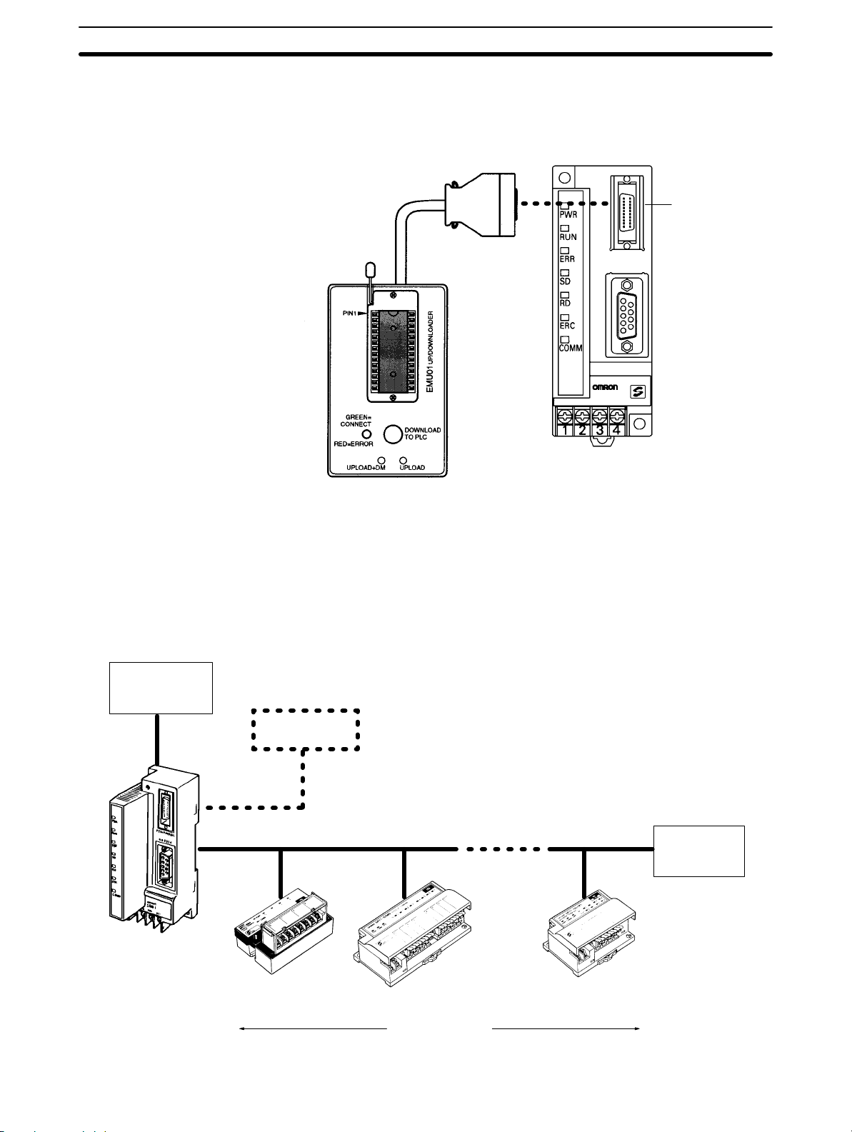
Expansion Memory Unit
The CPM1-EMU01-V1 Expansion Memory Unit is a program loader for smallsize or micro PCs. Using the CPM1-EMU01-V1, simple on-site transfer of user
programs and data memory is possible with PCs.
Peripheral port
PERIPHERAL
RS-232C
1-2 System Configuration
1-2-1 Basic Configuration
Host device
Peripheral
device
CompoBus/S Communications Cable
SRM1
Terminator
Slave Slave Slave
32 Slaves max.
3
Page 15
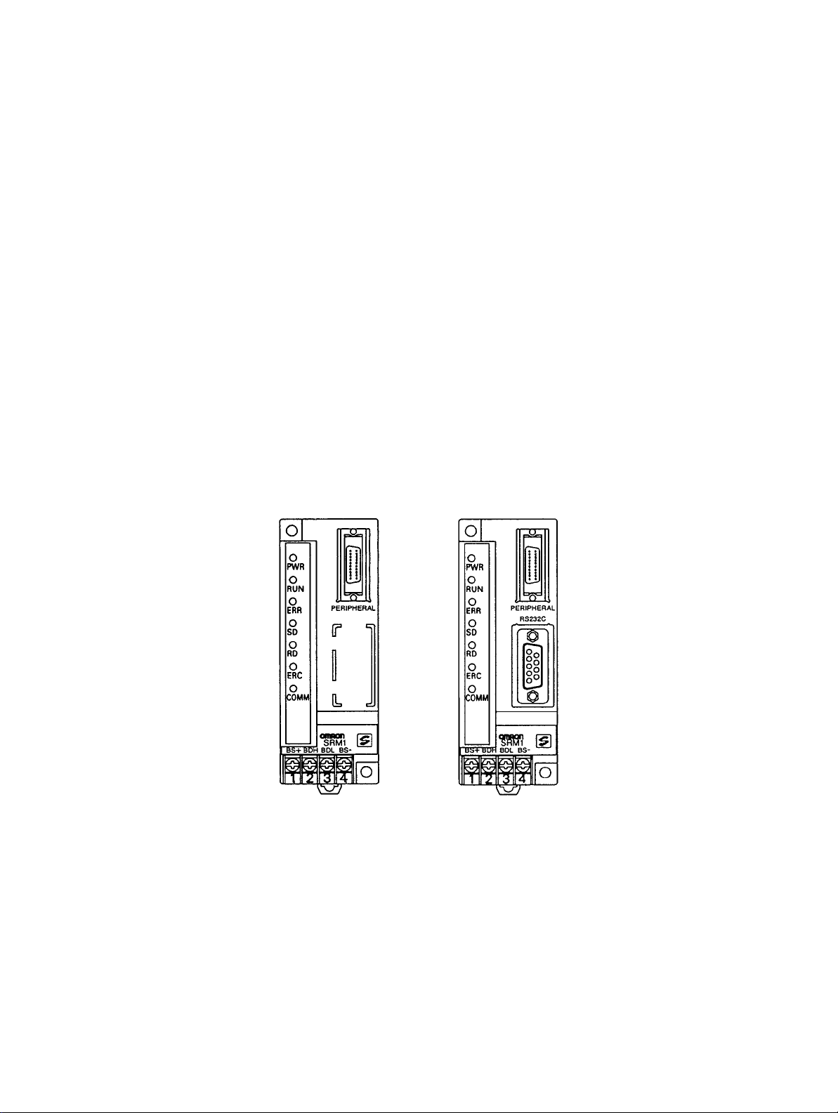
1-2-2 SRM1 Models
1-2SectionSystem Configuration
Model RS-232C port PT programming functions
SRM1-C01-V2 No No
SRM1-C02-V2 Yes Yes
The following table compares the functions in the SRM1(-V2) PCs with the functions in earlier SRM1 PCs.
Function
SRM1-C0j-V2 SRM1-C0j-V1 SRM1-C0j
Data backup Backed up by a lithium battery with a minimum lifetime of 10
years at 25_C.
Programming
Console functions
Data processing Bit data (ON/OFF for 16 bits) and 16-bit
Communications High-speed communications (previous
Connections with
host devices
Instructions The instructions in earlier SRM1 PCs plus
Programming can be performed through a Programming
Console connected to the peripheral port or an OMRON PT
connected to the RS-232C port.
analog data from Analog Units
mode) or long-distance communications
mode
Host Link, no-protocol, 1:1 NT Link, 1:N NT
Link, and 1:1 PC Link communications
the following instructions:
NEG(––), PID(––), SCL(66), and ZCP(––)
SRM1 models
Bit data (ON/OFF status of bits)
High-speed communications mode (previous
mode) only.
Host Link, no-protocol, 1:1 NT Link, and 1:1 PC
Link communications
Basic instructions: 14
Special instructions: 77 (123 variations)
Note The Analog Terminal can be used as a slave only with version-2 models. Incor-
rect data may be transferred if an Analog Terminal is used with the wrong model.
Capacitor backup
Programming can be performed
through a Programming Console
connected to the peripheral port.
SRM1-C01-V2
(No RS-232C port)
Peripheral port
SRM1-C02-V2
(With RS-232C port)
Peripheral port
RS-232C port
4
Page 16

1-2SectionSystem Configuration
1-2-3 Peripheral Connections
The following peripherals can be connected to the SRM1(-V2) PCs. Refer to
Appendix A Standard Models for a complete list of connectable peripherals.
Slaves The following table shows the Slaves that can be connected. Refer to the Com-
poBus/S Operation Manual (W266) for more details.
Slave SRT2 Series
High-speed or long-distance
Remote Terminals
(transistors)
Connector
Terminals
(transistors)
Remote Terminals
(relays)
Remote Terminals
(power MOSFET)
Remote Modules None
Analog Input
Terminal
Analog Output
Terminal
Sensor Amplifier
Terminals
Sensor Terminals
SRT2-ID04 SRT1-ID04
SRT2-ID04-1 SRT1-ID04-1
SRT2-ID08 SRT1-ID08
SRT2-ID08-1 SRT1-ID08-1
SRT2-ID16 SRT1-ID16
SRT2-ID16-1 SRT1-ID16-1
SRT2-ID16T
SRT2-ID16T-1
SRT2-OD04 SRT1-OD04
SRT2-OD04-1 SRT1-OD04-1
SRT2-OD08 SRT1-OD08
SRT2-OD08-1 SRT1-OD08-1
SRT2-OD16 SRT1-OD16
SRT2-OD16-1 SRT1-OD16-1
SRT2-OD16T
SRT2-OD16T-1
SRT2-MD16T
SRT2-MD16T-1
SRT2-VID08S
SRT2-VID08S-1
SRT2-VID16ML
SRT2-VID16ML-1
SRT2-VOD08S
SRT2-VOD08S-1
SRT2-VOD16ML
SRT2-VOD16ML-1
SRT2-ROC08 SRT1-ROC08
SRT2-ROC16 SRT1-ROC16
SRT2-ROF08 SRT1-ROF08
SRT2-ROF16 SRT1-ROF16
SRT2-AD04
SRT2-DA02
SRT2-TID04S (See note 3.) SRT1-TID04S
SRT2-TKD04S (See note 3.) SRT1-TKD04S
SRT2-ID08S (See note 3.) SRT1-ID08S
SRT2-OD08S (See note 3.) SRT1-OD08S
SRT2-MD08S (See note 3.) SRT1-MD08S
communications
SRT1 Series
High-speed
communications only
None
None
None
SRT1-ROF08
SRT1-ROF16
None
5
Page 17
1-2SectionSystem Configuration
Compatible
Communications Modes
Slave SRT1 Series
High-speed or long-distance
Bit Chain Terminal None SRT1-B1T
I/O Link Unit CPM1A-SRT21 None
SRT2 Series
communications
High-speed
communications only
Note 1. SRT1-series Remote Terminals and Sensor Terminals can operate in high-
speed communications mode only. Be sure to use SRT2-series Remote Terminals and Sensor Terminals when the SRM1-C0j-V2 is used in long-dis-
tance communications mode.
2. The Analog I/O Terminals can be used with SRM1-C0j-V2 only.
3. To be marketed in the near future.
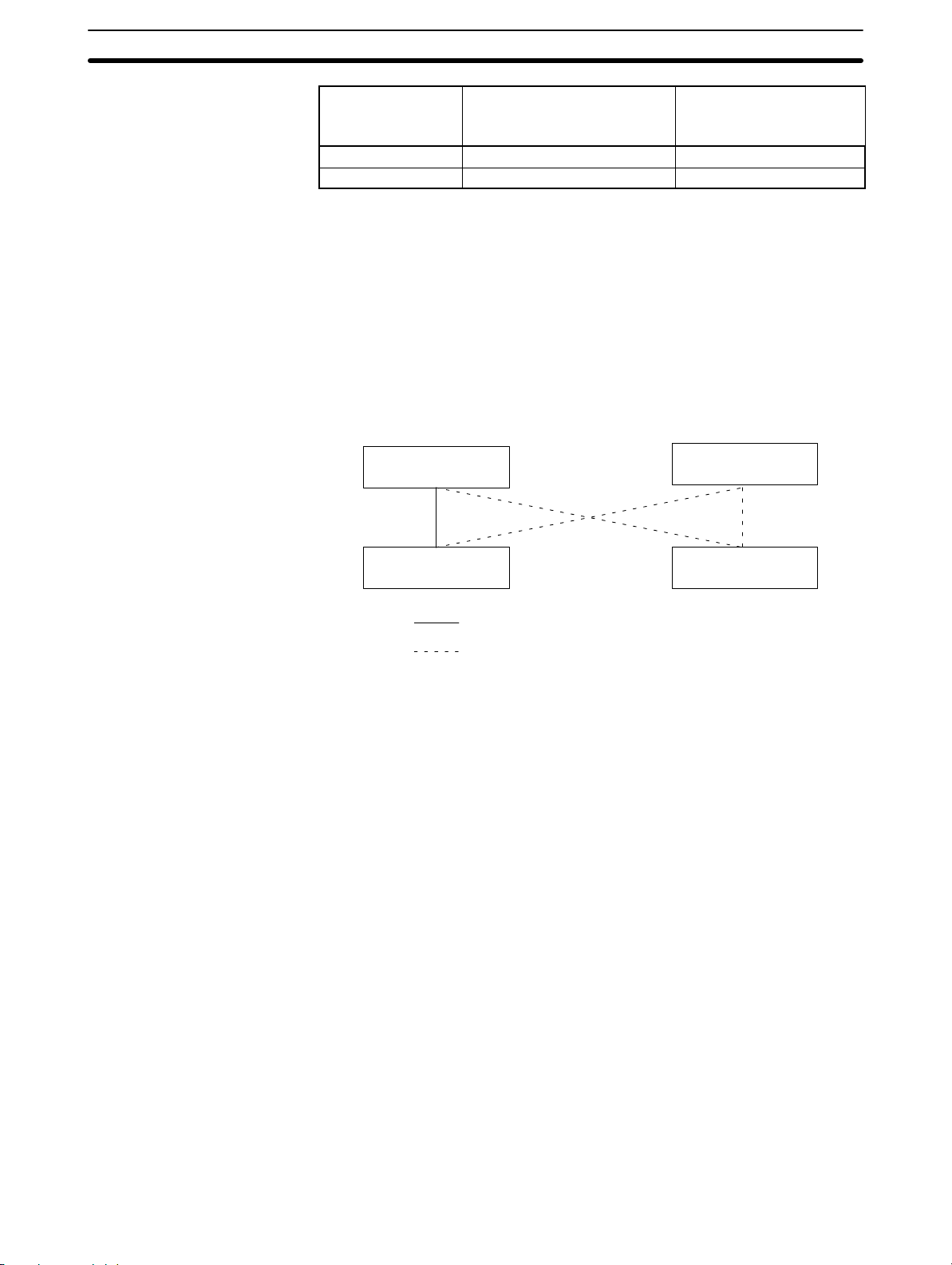
The long-distance communications mode can be used between SRM1-C0j-V2
Master Control Units and SRT2-series Slaves only, as shown in the following
diagram. High-speed mode must be used if even one SRT1-series Slave is included in the CompoBus/S system.
Master Control Unit
SRM1-C0j-V2
Master Control Unit
SRM1-C0j,
SRM1-C0j-V1
Peripheral Devices
SRT2-series Slave
High-speed or long-distance communications mode
High-speed communications mode only
SRT2-series Slave
The SRM1 can use a Programming Console or a personal computer running
CX-Programmer, SYSMAC Support Software (SSS), or SYSMAC-CPT as a Peripheral Device.
Programming Console
Programming Consoles are compact Peripheral Devices that support basic
functions such as writing ladder programs and monitoring SRM1 operation.
They are useful for onsite operations.
Refer to Section 4 Using a Programming Console for details on Programming
Console operations.
SYSMAC Support Software (SSS), SYSMAC-CPT, and CX-Programmer
In addition to the basic Programming Console operations, the CX-Programmer,
SYSMAC-CPT, and SSS can be used to edit ladder programs offline, save programs to disk, and perform high-level monitoring; the CX-Programmer, SYSMAC-CPT and SSS functions allow the user to design more efficient ladder programs. Refer to the manuals listed on the About this Manual page for details on
using them.
SYSMAC Support Software (SSS)
When using the SSS, set the PC model to the “CQM1” and observe the following
restrictions.
• Addresses will be checked according to the CQM1 address ranges, which are
wider than the SRM1 address ranges. Be sure to use only the allowable addresses.
• The CQM1 has a larger memory than the SRM1 and the amount of memory
available display will not be correct. Allow for the difference between capacities.
6
Page 18

1-3SectionProcedures From System Design to Test Operation
• Instructions will be displayed that are not supported by the SRM1. Do not use
these instructions.
CX-Programmer and SYSMAC-CPT
The following instructions cannot be programmed when using the CX-Programmer or SYSMAC-CPT. Errors will occur if an attempt is made to transfer them
from the PC to the computer: SCL(66)/@SCL(66), ZCP, NEG/@NEG, and PID.
Host Computers, PTs, and
PCs
An SRM1(-V2) can be connected an IBM PC/AT or compatible computer or OMRON PT through an RS-232C Adapter (CPM1-CIF01) mounted to the SRM1’s
peripheral port. (Use Host Link mode when connecting a PT through an
RS-232C Adapter.)
The RS-232C port on an SRM1-C02-V2 can be used to connect directly to an
IBM PC/AT or compatible computer, OMRON PT, or PC (C200HX/HG/HE,
C200HS, CQM1, C P M 1 , CPM1A, CPM2A, or CPM2C). (Use Host Link mode or
NT Link mode when connecting a PT directly.)
1-3 Procedures From System Design to Test Operation
The procedures from system design to test operation are explained in the sections of this manual as follows and in the CPM1/CPM1A/CPM2A/CPM2C/
SRM1(-V2) Programming Manual (W353):
1, 2, 3... 1. System Design
Refer to 3-1 System Design.
2. Installation
Refer to 3-3 Installing the SRM1.
3. Wiring
Refer to 3-4 Wiring and Connections.
4. Creating the Ladder Program
Refer to the relevant sections in the CPM1/CPM1A/CPM2A/CPM2C/
SRM1(-V2) Programming Manual (W353) and the applicable PC manual.
5. Inputting the Program
Refer to Section 4 Using the Programming Console, Section 5 Test Runs
and Error Processing, CX-Programmer Users Manual (W346), SYSMAC
Support Software (SSS) Operation Manuals (W247 and W248), and SYSMAC-CPT Support Software Quick Start Guide (W332) and User Manual
(W333).
6. Test Operation
Refer to 5-1-2 SRM1 Test Run Procedure.
7
Page 19

1-4 I/O and Data Area Allocations
1-4-1 I/O Allocations
The input bits of SRM1 words 000 to 007, and the output bits of words 010 to 017,
are allocated to the CompoBus/S Slave. These allocations are shown in the following table.
1-4SectionI/O and Data Area Allocations
Bits
Inputs
Outputs
I/O Word address
15 to 08 07 to 00
000 IN1 IN0
001 IN3 IN2
002 IN5 IN4
003 IN7 IN6
004 IN9 IN8
005 IN11 IN10
006 IN13 IN12
007 IN15 IN14
010 OUT1 OUT0
011 OUT3 OUT2
012 OUT5 OUT4
013 OUT7 OUT6
014 OUT9 OUT8
015 OUT11 OUT10
016 OUT13 OUT12
017 OUT15 OUT14
IN0 to IN15 are Input Slave node numbers, and OUT0 to OUT15 are Output
Slave node numbers.
If the maximum number of CompoBus/S devices is set to 16, then IN8 to IN15
and OUT8 to OUT15 can be used as work bits.
Words IR 008, IR 009, IR 018, and IR 019 can be used as work words.
The bits for two node number are allocated to 16-point Slaves so that all bits are
in the same word. If an even node address is set, the node address that is set
and the next node address following it will be used. For example, if node address
6 is set for a 16-point Output Slave, bits for node addresses OUT6 and OUT7 will
be used. If an odd node address is set, the node address that is set and the previous node address will be used. For example, if node address 3 is set for a
16-point Output Slave, bits for node addresses OUT2 and OUT3 will be used.
All of the bits for one node address are allocated to a 4-point Slave. If an even
numbered node address is set, bits 00 to 03 are used and bits 04 to 07 are not
used. If a n odd numbered node address is set, bits 8 to 11 are used and bits 12 to
15 are not used.
8
Page 20

1-4SectionI/O and Data Area Allocations
Analog Terminals are allocated from 16 to 64 bits per Terminals as shown in the
following table. If an allocation is not completely within the input or output area,
communications will not be possible and the COMM indicator will not be lit.
I/O bits allocated Node
64 bits
(SRT2-AD04, 4 analog inputs)
48 bits
(SRT2-AD04, 3 analog inputs)
32 bits
(SRT2-AD04, 2 analog inputs)
(SRT2-DA02, 2 analog outputs)
16 bits
(SRT2-AD04, 1 analog input)
(SRT2-DA02, 1 analog output)
Examples
If node address 3 is set for the SRT2-DA02 and 2 analog outputs are used, 32
bits are allocated from OUT2 to OUT5.
If node address 10 is set for the SRT2-AD04 and 4 analog inputs are used, the
allocated area would exceed the output area available for allocation and communications would not be possible.
1-4-2 Data Area Allocation
Node addresses used Address
address
setting
Even Set address to set address + 7
Odd Set address – 1 to set address + 6
Even Set address to set address + 5
Odd Set address – 1 to set address + 4
Even Set address to set address + 3
Odd Set address – 1 to set address + 2
Even Set address to set address + 1
Odd Set address – 1 to set address
setting range
0 to 9
0 to 11
0 to 13
0 to 15
The relationships between the data areas and words that can be used by the
SRM1 are shown in the following table. For details, refer to the CPM1/CPM1A/
CPM2A/CPM2C/SRM1(-V2) Programming Manual (W353).
Name Number of words or bits Word addresses
Input bits 8 words IR 000 to IR 007
Output bits 8 words IR 010 to IR 017
Work bits 44 words
(See note 1.)
SR area 16 words IR 240 to IR 255
HR area 20 words HR 00 to HR 19
AR area 16 words AR 10 to AR 15
LR area 16 words LR 00 to LR 15
DM area (Read/Write) 2,022 words DM 0000 to DM 2021
DM area (Read Only) 456 words DM 6144 to DM 6599
DM area (PC Setup) 56 words DM 6600 to DM 6655
TR area 8 bits TR 0 to TR 7
TIM/CNT area 128 bits TIM/CNT 000 to 127
IR 008 and IR 009,
IR 018 and IR 019,
IR 200 to IR 239
(See note 2.)
Note 1. When the CompoBus/S system is used in 128-bit mode, IR 004 to IR 007
and IR 014 to IR 017 can be used as work words.
2. AR 04 to AR 07 are used for Slave status.
9
Page 21

SECTION 2
Specifications and Components
This section provides the technical specifications of the SRM1(-V2) and describes its main components.
2-1 Specifications 12. . . . . . . . . . . . . . . . . . . . . . . . . . . . . . . . . . . . . . . . . . . . . . . . . . . . . . . . . . . .
2-1-1 General Specifications 12. . . . . . . . . . . . . . . . . . . . . . . . . . . . . . . . . . . . . . . . . . . . . .
2-1-2 Characteristics 13. . . . . . . . . . . . . . . . . . . . . . . . . . . . . . . . . . . . . . . . . . . . . . . . . . . .
2-1-3 CompoBus/S Communications Specifications 14. . . . . . . . . . . . . . . . . . . . . . . . . . .
2-2 Unit Components 15. . . . . . . . . . . . . . . . . . . . . . . . . . . . . . . . . . . . . . . . . . . . . . . . . . . . . . . . .
11
Page 22

2-1 Specifications
2-1-1 General Specifications
Item SRM1-C01/C02-V2
Supply voltage 24 VDC
Allowable supply voltage 20.4 to 26.4 VDC
Power consumption 3.5 W max.
Inrush current 5.0 A max. (pulse width: 15 ms max.)
Noise immunity Conforms to IEC61000-4-4; 2 kV (power lines)
Vibration resistance 10 to 57 Hz, 0.075-mm amplitude, 57 to 150 Hz, acceleration: 9.8 m/s2 in X, Y, and
Z directions for 80 minutes each
(Time coefficient; 8 minutes × coefficient factor 10 = total time 80 minutes)
Shock resistance 147 m/s2 three times each in X, Y, and Z directions
Ambient temperature Operating: 0°C to 55°C
Storage: –20°C to 75°C
Absolute humidity 10% to 90% (with no condensation)
Atmosphere Must be free from corrosive gas.
Terminal screw size M3
Power interrupt time DC type: 2 ms min.
Weight 150 g max.
2-1SectionSpecifications
12
Page 23

2-1-2 Characteristics
Item SRM1-C01/C02-V2
Control method Stored program method
I/O control method Cyclic scan method
Programming language Ladder diagram
Instruction length 1 step per instruction, 1 to 5 words per instruction
Types of instructions Basic instructions: 14
Special instructions: 81 instructions, 125 variations
Execution time Basic instructions: 0.97 µs (LD instruction)
Special instructions: 9.1 µs (MOV instruction)
Program capacity 4,096 words
Maximum number of I/O points 256 points
Input bits 00000 to 00715 (Words not used as input words can be used as work words.)
Output bits 01000 to 01715 (Bits not used as output bits can be used as work bits.)
Work bits 704 bits: 00800 to 00915 (Words IR 008 and IR 009)
01800 to 01915 (Words IR 018 and IR 019)
20000 to 23915 (Words IR 200 to IR 239)
Special bits (SR area) 248 bits: 24000 to 25507 (Words IR 240 to IR 255)
Temporary bits (TR area) 8 bits (TR0 to TR7)
Holding bits (HR area) 320 bits: HR 0000 to HR 1915 (Words HR 00 to HR 19)
Auxiliary bits (AR area) 256 bits: AR 0000 to AR 1515 (Words AR 00 to AR 15)
Link bits (LR area) 256 bits: LR 0000 to LR 1515 (Words LR 00 to LR 15)
Timers/Counters 128 timers/counters (TIM/CNT 000 to TIM/CNT 127)
100-ms timers: TIM 000 to TIM 127
10-ms timers (high-speed counter): TIM 000 to TIM 003
Decrementing counters and reversible counters
(Note: TIMH(15) will not time reliably if the cycle time is over 10 ms and timer
numbers TIM 004 to TIM 127 are used.)
Data memory Read/Write: 2,022 words (DM 0000 to DM 2021)
Read-only: 512 words (DM 6144 to DM 6655)
Interval timer interrupts One-shot mode/Scheduled interrupt mode, one bit (0.5 to 319,968 ms)
Memory protection HR, AR, and DM area contents; and counter values maintained during power
interruptions.
Memory backup Flash memory:
The program and read-only DM area are backed up without a battery.
Lithium battery backup:
The read/write DM area, HR area, AR area, and counter values are backed up by
the lithium battery whose service life extends over ten years under an ambient
temperature of 25_C.
(Note: The lifetime of the lithium battery capacity depends on the ambient
temperature. Refer to the descriptions on the next page.)
Self-diagnostic functions CPU Unit failure (watchdog timer), memory check, communications errors, setting
errors
Program checks No END instruction, programming errors (continuously checked during operation)
Peripheral port One point; tool connection, Host Link, no protocol
RS-232C Port One point (SRM1-C02-V2 only); Host Link, 1:1 NT Link, 1:N NT Link, 1:1 PC Link,
no protocol
2-1SectionSpecifications
13
Page 24

2-1SectionSpecifications
Backup Time vs. Temperature A lithium battery in the CPU Unit is used to back up the contents in the user pro-
gram area, the READ/WRITE area in the Data Memory (DM), Hold Relay (HR),
the Auxiliary Memory Relay (AR), and in the data area of the Counter (CNT). The
deterioration of the lithium battery capacity depends on the ambient temperature. The standard service life is 12 years under an ambient temperature of 40_C
when operating 8 hours a day.
If the power supply is interrupted after the lithium battery capacity has deteriorated, the contents in the user program area, the READ/WRITE area in the Data
Memory (DM), Hold Relay (HR), Auxiliary Memory Relay (AR), and in the data
area of the Counter (CNT) may be lost. Even if the contents of the CPU Unit’s
program area are lost, however, the user program and DM read-only contents
(including the one in the PC Setup area) stored in flash memory will be read to
the CPU Unit’s user program area when the SRM1 is next started up.
2-1-3 CompoBus/S Communications Specifications
Item Specifications
Communications method CompoBus special protocol
Transmission method Multi-drop, T-branch
Baud rate
Modulation method Baseband method
Code method Manchester coding method
Maximum number of connectible
terminals
Number of points per frame
Communications High-speed
cycle time communications
Communications function Cyclic transfer only (no message communications)
Error control checks Manchester code check, frame length check, parity check, two-transfer
Communications
distance
Cable
High-speed
communications
mode
Long-distance
communications
mode
mode
Long-distance
communications
mode
High-speed
communications
mode
Long-distance
communications
mode
Vinyl-clad VCTF
JIS C 3306
Flat cable Four 0.75 mm2 conductors (2 signal wires and 2 power supply wires)
750 kbps
93.75 kbps
32: 16 IN and 16 OUT
16: 8 IN and 8 OUT
256 (128 IN and 128 OUT), when maximum number of connectible terminals
is 32.
128 (64 IN and 64 OUT), when maximum number of connectible terminals is
16.
0.8 ms, when maximum number of terminals is set to 32.
0.5 ms, when maximum number of terminals is set to 16.
6.0 ms, when maximum number of terminals is set to 32.
4.0 ms, when maximum number of terminals is set to 16.
comparison
Main line length: 100 m max.
Branch line length: 3 m max.
Total branch line length: 50 m max.
Main line length: 500 m max.
Branch line length: 6 m max.
Total branch line length: 120 m max.
Two 0.75 mm2 conductors (2 signal wires)
14
Page 25
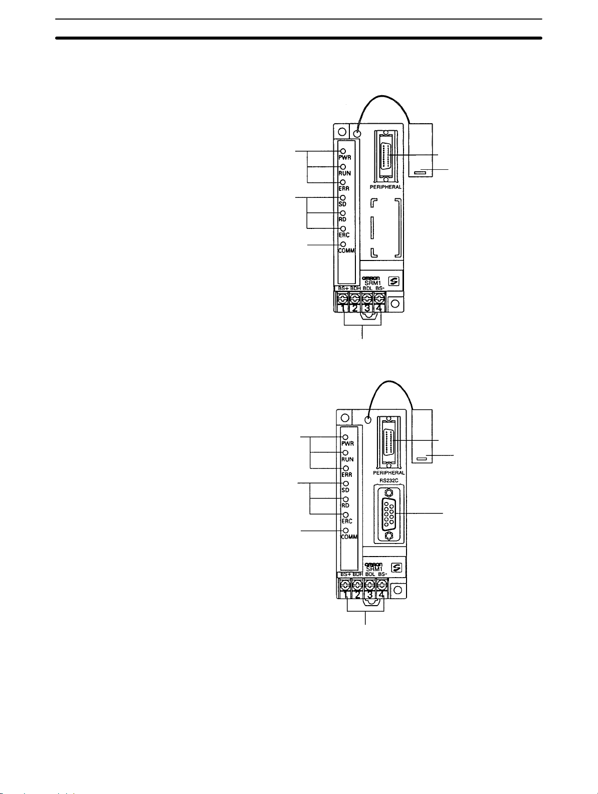
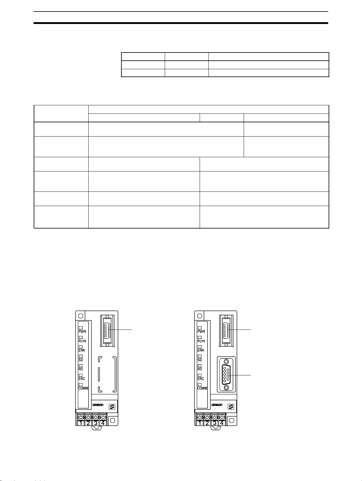
2-2 Unit Components
SRM1-C01-V2
2-2SectionUnit Components
4. CPU Unit status indicators
5. CompoBus/S communications status indicators
6. Peripheral/RS-232C port communications status indicators
SRM1-C02-V2
4. CPU Unit status indicators
2. Peripheral port
Connector cover
1. Terminal block
2. Peripheral port
Connector cover
5. CompoBus/S communications status indicators
3. RS-232C Port
6. Peripheral/RS-232C Port communications status indicators
1. Terminal block
1) Terminal Block These terminals connect the power supply (24 V) and the CompoBus/S transmission path. For details regarding power supply wiring, refer to 3-4-2 Power
Supply Wiring.
2) Peripheral Port The Peripheral Port connects the programming tool or an RS-232C or RS-422
adapter. Be sure to use the correct cable.
3) RS-232C Port The RS-232C Port connects to an RS-232C interface such as a personal computer or an OMRON PT. For details, refer to 3-4-4 RS-232C Port Wiring.
15
Page 26

2-2SectionUnit Components
4, 5, 6) Indicators There are three types of LED indicators: CPU Unit status indicators, CompoBus/
S communications status indicators, and peripheral/RS-232C Port communications status indicators. These indicate the status of various Units, as shown in
the following table.
Indicator Display Status
PWR (Green)
RUN (Green)
ERR (Red)
SD (Yellow)
RD (Yellow)
ERC (Red)
COMM (Yellow)
ON Power is being supplied.
OFF Power is not being supplied.
ON In RUN mode or MONITOR mode
OFF In PROGRAM mode or fatal error has occurred.
ON Fatal error has occurred.
Flashing Non-fatal error has occurred.
OFF Normal operation
ON CompoBus/S data is being sent.
OFF Data is not being sent.
ON CompoBus/S data is being received.
OFF Data is not being received.
ON A CompoBus/S communications error has
occurred.
OFF Normal operation
Flashing Data is being sent or received at the Peripheral
Port or RS-232C Port.
OFF Data is not being sent or received.
16
Page 27

SECTION 3
Installation and Wiring
This section explains how to install and wire the SRM1(-V2). Be sure to follow the instructions contained here concerning the
control panel, power supply , CompoBus/S transmissions, and RS-232C Port wiring. For details regarding the wiring of CompoBus/S Terminal transmission paths and I/O, refer to the CompoBus/S Operation Manual (W266).
3-1 System Design 18. . . . . . . . . . . . . . . . . . . . . . . . . . . . . . . . . . . . . . . . . . . . . . . . . . . . . . . . . . .
3-1-1 Power Supply Wiring 18. . . . . . . . . . . . . . . . . . . . . . . . . . . . . . . . . . . . . . . . . . . . . . .
3-1-2 Interlock and Limit Circuits 18. . . . . . . . . . . . . . . . . . . . . . . . . . . . . . . . . . . . . . . . . .
3-1-3 Power Supply Sequence 18. . . . . . . . . . . . . . . . . . . . . . . . . . . . . . . . . . . . . . . . . . . . .
3-2 Selecting an Installation Site 19. . . . . . . . . . . . . . . . . . . . . . . . . . . . . . . . . . . . . . . . . . . . . . . .
3-2-1 Installation Site Conditions 19. . . . . . . . . . . . . . . . . . . . . . . . . . . . . . . . . . . . . . . . . .
3-2-2 Panel/Cabinet Installation 19. . . . . . . . . . . . . . . . . . . . . . . . . . . . . . . . . . . . . . . . . . .
3-3 Installing the SRM1 20. . . . . . . . . . . . . . . . . . . . . . . . . . . . . . . . . . . . . . . . . . . . . . . . . . . . . . .
3-3-1 Surface Installation 20. . . . . . . . . . . . . . . . . . . . . . . . . . . . . . . . . . . . . . . . . . . . . . . .
3-3-2 DIN Track Installation 20. . . . . . . . . . . . . . . . . . . . . . . . . . . . . . . . . . . . . . . . . . . . . .
3-4 Wiring and Connections 21. . . . . . . . . . . . . . . . . . . . . . . . . . . . . . . . . . . . . . . . . . . . . . . . . . . .
3-4-1 General Precautions for Wiring 21. . . . . . . . . . . . . . . . . . . . . . . . . . . . . . . . . . . . . . .
3-4-2 Power Supply Wiring 23. . . . . . . . . . . . . . . . . . . . . . . . . . . . . . . . . . . . . . . . . . . . . . .
3-4-3 CompoBus/S Transmission Line Wiring 23. . . . . . . . . . . . . . . . . . . . . . . . . . . . . . . .
3-4-4 RS-232C Port Wiring 24. . . . . . . . . . . . . . . . . . . . . . . . . . . . . . . . . . . . . . . . . . . . . . .
3-4-5 Host Link Connections 26. . . . . . . . . . . . . . . . . . . . . . . . . . . . . . . . . . . . . . . . . . . . .
3-5 One-to-one NT Link 30. . . . . . . . . . . . . . . . . . . . . . . . . . . . . . . . . . . . . . . . . . . . . . . . . . . . . . .
3-6 One-to-N NT Link 30. . . . . . . . . . . . . . . . . . . . . . . . . . . . . . . . . . . . . . . . . . . . . . . . . . . . . . . .
3-7 One-to-one PC Link Connections 31. . . . . . . . . . . . . . . . . . . . . . . . . . . . . . . . . . . . . . . . . . . .
3-7-1 Basics 31. . . . . . . . . . . . . . . . . . . . . . . . . . . . . . . . . . . . . . . . . . . . . . . . . . . . . . . . . . .
3-7-2 Restrictions 32. . . . . . . . . . . . . . . . . . . . . . . . . . . . . . . . . . . . . . . . . . . . . . . . . . . . . .
3-7-3 Cable Connections 32. . . . . . . . . . . . . . . . . . . . . . . . . . . . . . . . . . . . . . . . . . . . . . . . .
3-7-4 PC Setup Settings 32. . . . . . . . . . . . . . . . . . . . . . . . . . . . . . . . . . . . . . . . . . . . . . . . . .
17
Page 28
3-1 System Design
Take the points covered in this section into consideration when designing the
system.
3-1-1 Power Supply Wiring
Separate the power supply wiring from the control system, SRM1 system, and
DC I/O system wiring.
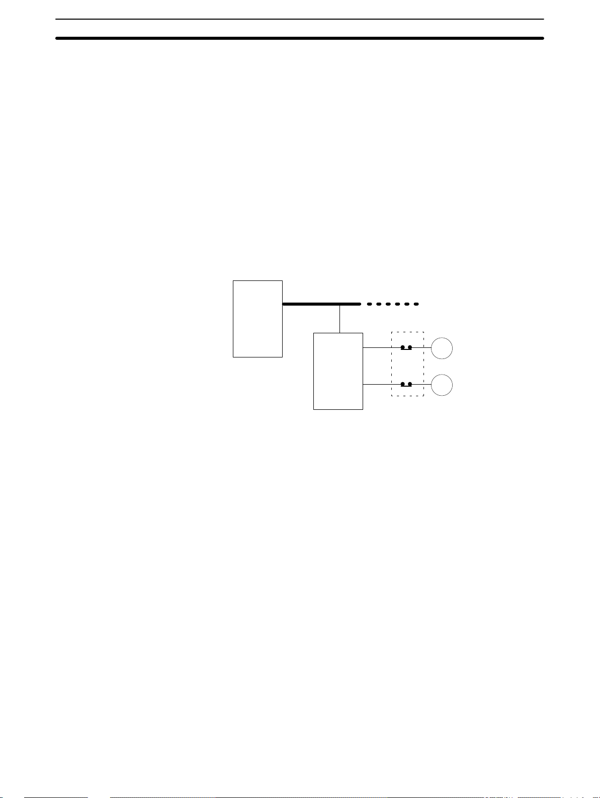
3-1-2 Interlock and Limit Circuits
Construct an external interlock circuit if SRM1 outputs are used to perform reciprocal operations such as controlling the forward and reverse operation of a motor or if incorrect SRM1 operation could cause accidents or mechanical damage.
Also, construct an external limit circuit to prevent run-away movement in operations such as position control.
The following diagram shows an example of an interlock circuit.
3-1SectionSystem Design
CompoBus/S transmission path
SRM1
In the interlock circuit above, MC1 and MC2 cannot be ON at the same time even
if SRM1 outputs 01005 and 01006 are both ON at the same time (an incorrect
operation).
3-1-3 Power Supply Sequence
Time Up to the Start of Operation
The time from when the power supply is turned on to when the operation starts
varies depending on the operation conditions such as power supply voltage,
configuration, ambient temperature, etc. The minimum time is approximately
500 ms and the maximum is approximately 1.1 s.
Momentary Power Failure Detection
A momentary power failure (i.e., a voltage drop to less than 85% of the rated voltage) lasting less than 2 ms is not detected and the SRM1 continues to operate.
A momentary power failure lasting longer than 2 ms may cause the SRM1 to
stop operation. If this occurs, operation will be automatically resumed when the
rated voltage again rises above 85%.
Slave
Interlock Circuit
01005
01006
MC2
MC1
MC1
MC2
Motor forward
Motor reverse
18
Note The SRM1 may repeat stop/start operations if the supply voltage of less than
85% of the rated value gradually goes up or down. If this affects the equipment,
etc., provide a protection circuit which shuts off the output if the supply voltage is
not above the rated value.
The output status of Slaves when the SRM1 is stopped can be set on the Slave
side either to have the ON/OFF status directly prior to the stop retained or to
have all outputs turned OFF.
Page 29
3-2 Selecting an Installation Site
The SRM1 is resistant to harsh conditions and highly reliable, but installing it in a
favorable site will maximize its reliability and operating lifetime.
3-2-1 Installation Site Conditions
Avoid installing the SRM1 in a site with any of the following conditions.
• Where the SRM1 is exposed to direct sunlight.
• Where the ambient temperature is below 0°C or over 55°C.
• Where the SRM1 may be affected by condensation due to radical temperature
changes.
• Where the ambient humidity is below 10% or over 90%.
• Where there is any corrosive or inflammable gas.
• Where there is excessive dust, saline air, or metal powder.
• Where the SRM1 is affected by vibration or shock.
• Where any water, oil, or chemical may splash on the SRM1.
Be sure that the conditions at the installation site conform to the SRM1’s general
specifications. Refer to 2-1-1 General Specifications for details.
3-2SectionSelecting an Installation Site
3-2-2 Panel/Cabinet Installation
Consider PC operation, maintenance, and surrounding conditions when installing the SRM1 in a panel or cabinet.
Overheating The operating temperature range for the SRM1 is 0_C to 55_C. Be sure that
there is adequate ventilation for cooling.
• Allow enough space for air circulation.
• Do not install the SRM1 above equipment that generates a large amount of
heat, such as heaters, transformers, or large resistors.
• Install a cooling fan or system when the ambient temperature exceeds 55_C.
Control panel
Air vent
Fan
SRM1
Electrical Noise Power lines and high-voltage equipment can cause electrical noise in the PC.
• Do not install the SRM1 in a panel or cabinet with high-voltage equipment.
• Allow at least 200 mm between the SRM1 and nearby power lines.
200 mm min.
SRM1
200 mm min.
Power lines
19
Page 30
3-3SectionInstalling the SRM1
Accessibility Ensure that the SRM1 can be accessed for normal operation and maintenance.
• Provide a clear path to the SRM1 for operation and maintenance. High-voltage
equipment or power lines could be dangerous if they are in the way during routine operations.
• The SRM1 will be easiest to access if the panel or cabinet is installed about 3 to
5 feet off of the floor.
3-3 Installing the SRM1
The SRM1 can be installed on a horizontal surface or on a DIN track.
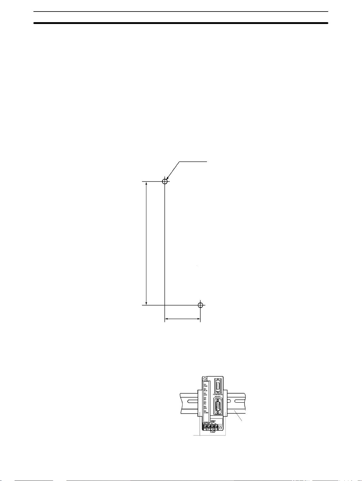
3-3-1 Surface Installation
Use the following pattern when installing an SRM1 on a horizontal surface.
Two M4 or two 4.2 dia.
3-3-2 DIN Track Installation
The SRM1 can be installed on a 35-mm DIN track.
100
30
(Unit: mm, with tolerance of
±0.2 mm)
20
End Plates
(PFP-M)
DIN Track
PFP-100N (1 m)
PFP-50N (50 cm)
Page 31

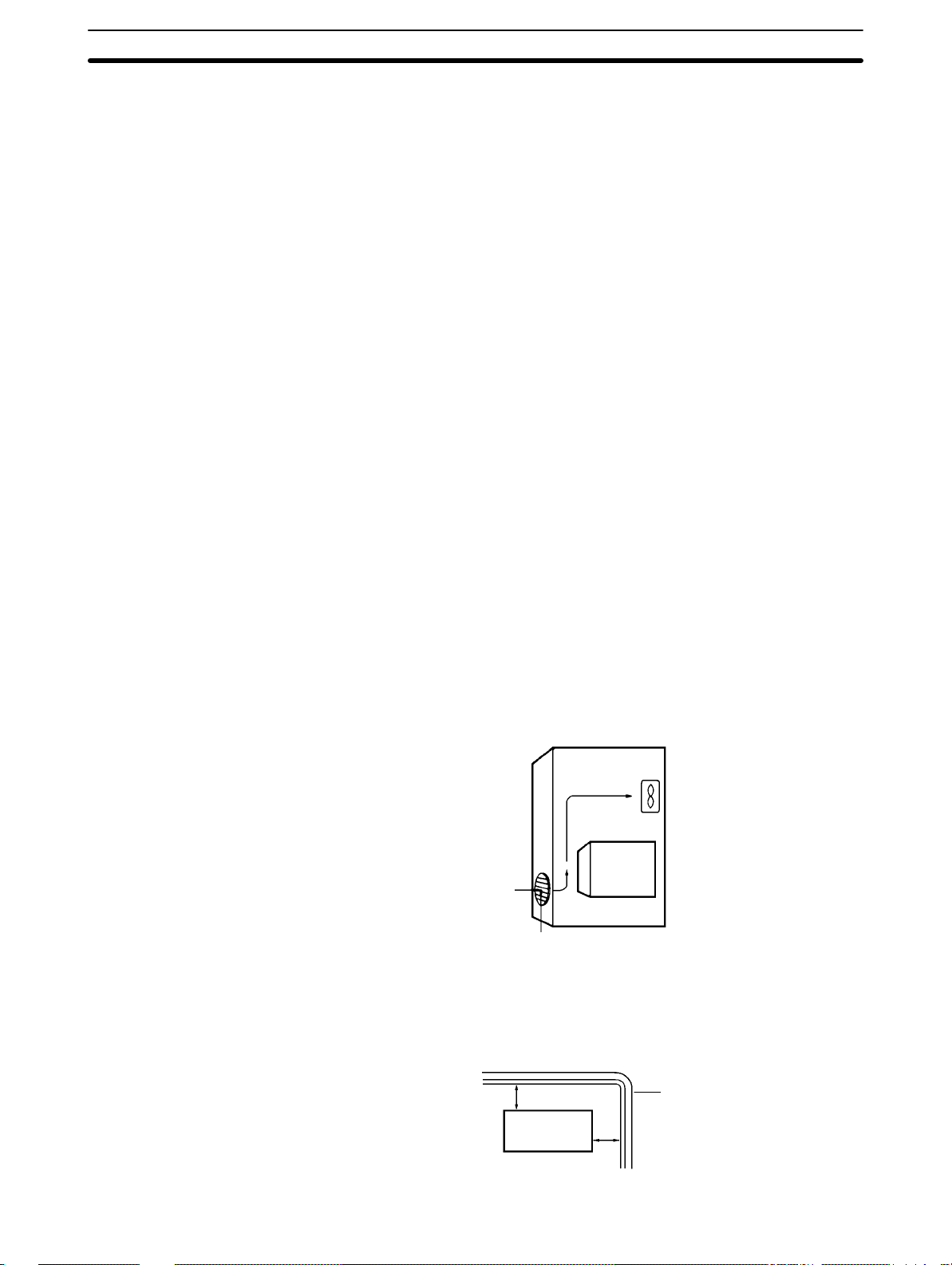
3-4SectionWiring and Connections
Installation
Lower the SRM1 so that the notch on the back of the Unit catches the top of the
DIN Track. Push the Unit forward until the lock snaps into place.
Removal
Pry the lock down with a standard screwdriver and pivot the Unit upward to remove it.
Screwdriver
3-4 Wiring and Connections
3-4-1 General Precautions for Wiring
I/O Line Noise To avoid noise, do not run CompoBus/S transmission lines in the same duct or
conduit as power lines.
Hanging Ducts
Leave at least 300 mm between the ducts, as shown in the following diagram.
CompoBus/S
transmission
lines
Control cables and
SRM1 power lines
300 mm min.
Power cables
300 mm min.
21
Page 32

3-4SectionWiring and Connections
Floor Ducts
Leave at least 200 mm between the wiring and the top of the duct, as shown in
the following diagram.
CompoBus/S
transmission lines
Control cables and
SRM1 power lines
Power cables
Metal plate (iron)
200 mm min.
Conduit
Separate the CompoBus/S transmission lines, power and control lines, and
power cables, as shown in the following diagram.
CompoBus/S
transmission lines
Control cables and
SRM1 power lines
Power cables
Terminal Connections Always use crimp connectors for the SRM1’s power lines and transmission
lines.
Use M3 terminal screws and tighten the screws securely (to a torque of
0.48 N S m).
Recommended Terminals: Use the terminals shown below.
Fork terminal
6.0 mm max. 6.0 mm max.
Round terminal
22
Page 33

3-4SectionWiring and Connections
3-4-2 Power Supply Wiring
Applicable Power Supply Use a power supply that conforms to specifications of at least 24 VDC and 3.5 W.
OMRON’s S82K-00724 is recommended (input: 100 VAC; output: 24 VDC,
7.5 W).
Note The above power supply is for a case where the CompoBus/S Slave is sepa-
rated from the power supply. Refer to the CompoBus/S Operation Manual
(W266) when supplying power to the whole system including the Slave.
Wiring Connections Wire the power supply as shown in the following diagram.
+
24 VDC
Note Be sure to ground the ground terminal of the power supply.
3-4-3 CompoBus/S Transmission Line Wiring
Applicable Cable Be sure to use the specified cable, and do not mix flat cable and VCTF cable.
Cable Model number Specifications
Special-purpose flat cable XBIT-W10 4-conductor flat cable:
0.75 mm
VCTF cable --- 2-conductor Vinyl-clad
VCTF JIS C3306
VCTF 0.75x2C
2
23
Page 34

3-4SectionWiring and Connections
Wiring Connections Wire the CompoBus/S transmission lines as shown in the following diagram.
Slave terminal block
BD
H
BD
L
BD H
BD L
3-4-4 RS-232C Port Wiring
Connector Pin Arrangement The following diagram shows the connector pin arrangement for the RS-232C
port, i.e., the SRM1 (SRM1-C02-V2) and RS-232C Adapter (CPM1-CIF01).
1
SD
2
RD
3
RS
4
CS
5
Cable Connections The following diagrams show the communications cable connections between
the RS-232C port, i.e., the SRM1 (SRM1-C02-V2) and RS-232C Adapter
(CPM1-CIF01), and the various external devices.
IBM PC/AT or
Compatible
Computer
CD
RD
SD
ER
SG
DR
RS
CS
CI
Pin No.Signal
1
2
3
4
5
6
7
8
9
RS-232C Port
Pin No. Signal
1
2
3
4
5
6
7
8
9
Hood
SD
RD
RS
CS
SG9
6
7
8
9
SG
–
–
–
–
24
Page 35

3-4SectionWiring and Connections
OMRON PT or PC*
Pin No.Signal
–
SD
RD
RS
CS
–
–
–
SG
*Host Link or NT Link with an OMRON PT, or 1:1 PC Link with a SYSMAC C200HX/HE/HG/HS, CQM1, or CPM1 Programmable Controller.
3G2A9-AL004-E
Link Adapter
FG
SD
RD
RS
CS
DR
SG
–
–
ER 20
1
2
3
4
5
6
7
8
9
Pin No.Signal
1
2
3
4
5
6
7
8
9
1:1 Connection
RS-232C Port
Pin No. Signal
1
2
3
4
5
6
7
8
9
9
RS-232C Port
Pin No. Signal
1
2
3
4
5
6
7
8
9
Hood
Hood
–
SD
RD
RS
CS
–
–
–
SG
–
SD
RD
RS
CS
–
–
–
SG9
(Recommended Cables)
XW2Z-200T: 2 m
XW2Z-500T: 5 m
3G2A9-AL004-E
Link Adapter
Pin No.Signal
FG
SD
RD
RS
CS
DR
SG
–
–
ER 20
1
2
3
4
5
6
7
8
9
1:N Connection
RS-232C Port
Pin No. Signal
1
2
3
4
5
6
7
8
9
–
SD
RD
RS
CS
–
–
–
SG9
Hood
25
Page 36

3-4SectionWiring and Connections
Ribbon line
(red)
Ribbon line
(black)
Ribbon line
(red)
Ribbon line
(black)
NT-AL001
–
RD
SD
RS
CS
–
–
–
SG
NT-AL001
–
RD
SD
RS
CS
–
–
–
SG
Pin No.Signal
1:1 Connection
1
2
3
4
5
6
7
8
9
1:N Connection
Pin No.Signal
1
2
3
4
5
6
7
8
9
RS-232C Port
Pin No. Signal
1
2
3
4
5
6
7
8
9
RS-232C Port
Pin No. Signal
1
2
3
4
5
6
7
8
9
–
SD
RD
RS
CS
–
–
–
SG9
Hood
–
SD
RD
RS
CS
–
–
–
SG9
Hood
3-4-5 Host Link Connections
Host Link is a command/response communications system in which commands
are transmitted from the host computer and corresponding responses are returned from the destination SRM1. Host Link commands can be used to read/
write data in SRM1 data areas and read/write settings. Either the peripheral port
or RS-232C port can be used.
Note For details on PC Setup settings, refer to 1-1 PC Setup or 4-4-1 Host Link Com-
munications) in the CPM1/CPM1A/CPM2A/CPM2C/SRM1(-V2) Programming
Manual (W353).
26
Host Link
computer
SRM1
Command
Response
Page 37

3-4SectionWiring and Connections
One-to-one Host Link
Connection
The SRM1 can be connected to an IBM PC/AT or compatible computer or a Programmable Terminal, as shown in the following diagram.
IBM PC/AT or
compatible
computer
Response
SRM1
Command
PT
Response
SRM1
Command
One-to-one Host Link Cables The cables differ depending on whether the peripheral port or RS-232C port is
used.
Peripheral Port Connection
OMRON PT
IBM PC/AT or
compatible
computer
SRM1
WX2Z-200T
WX2Z-500T
RS-232C Adapter
CPM1-CIF01
CQM1-CIF02
Note Set the RS-232C Adapter mode setting switch to “HOST.”
27
Page 38

OMRON PT
IBM PC/AT or
compatible
computer
Note For details regarding RS-232C connections, refer to 3-4-4 RS-232C Port Wiring.
One-to-N Host Link Connection
3-4SectionWiring and Connections
RS-232C Port Connection
SRM1
WX2Z-200T
WX2Z-500T
IBM PC/AT or
compatible
computer
Response
NT-AL001
SRM1
Link Adapter
3G2A9-AL004-E
RS-422
Adapter
Command
SRM1
28
Page 39

3-4SectionWiring and Connections
One-to-N Host Link Cables Up to 32 SRM1s can be connected to the computer via the peripheral port or
RS-232C port.
IBM PC/AT or compatible computer
Make a straight RS-232C cable connection between the 3G2A9-AL004-E
Link Adapter the personal computer, and match each SD, RD, and SG.
Link Adapter
3G2A9-AL004-E
D-sub 9-pin
Pin No.Signal
RDB
–
SG
–
SDB
RDA
FG
–
SDA
1
2
3
4
5
6
7
8
9
NT-AL001
Connecting Cables
(Refer to page 26.)
RS-422 Adapter
CPM1-CIF11
SRM1
SRM1
Note 1. The maximum total length of the RS-422 cable is 500 meters.
2. Turn ON the termination resistance switches for only the Link Adapters or
RS-422 Adapters at both ends of the Host Link network.
3. Crimp-type terminals must be used for Link Adapter and RS-422 Adapter
terminal wiring. For details, refer to 3-4-1 General Precautions for Wiring.
29
Page 40

3-6SectionOne-to-N NT Link
3-5 One-to-one NT Link
High-speed communications can be achieved by providing a direct access
through the use of the 1:1 NT Link between the SRM1 and Programmable Terminal (PT). The RS-232C port can be used for NT Link. A 1:1 NT Link is only possible with a Master Control Unit that has an RS-232C port (SRM1-C02,
SRM1-C02-V1, or SRM1-C02-V2).
SRM1
Programmable Terminal
NT Link Cable Connections The SRM1 can be connected to a PT via the RS-232C port, as shown in the fol-
lowing illustration. For details regarding RS-232C connections, refer to 3-4-4
RS-232C Port Wiring.
SRM1
Programmable Terminal
XW2Z-200T
XW2Z-500T
PC Setup Settings Set the RS-232C port’s communications mode to 1:1 NT Link in DM 6645 in the
PC Setup. For details, refer to 1-1 PC Setup or 4-4-3 One-to-one NT Link Com-
munications in the CPM1/CPM1A/CPM2A/CPM2C/SRM1(-V2) Programming
Manual (W353).
3-6 One-to-N NT Link
The 1:N NT Link allows an SRM1-C02-V2 PC to be connected to as many as 8
OMRON Programmable Terminals (PTs) and direct access provides high-speed
communications. The RS-232C port is used to make the 1:N NT Link.
SRM1
OMRON PT
30
Page 41

3-7SectionOne-to-one PC Link Connections
The 1:N NT Link is possible only with the SRM1-C02-V2 PCs, which have an
RS-232C port.
Cable Connections The SRM1 can be connected to OMRON PTs via the RS-232C port, as shown in
the following illustration. OMRON PTs that support the 1:N NT Link must be
used.
SRM1
Programmable Terminals
RS-422
Note 1. For details on RS-422A connections, refer to the Programmable Terminal’s
Operation Manual.
2. For details on RS-232C connections, refer to 3-4-4 RS-232C Port Wiring.
NT-AL001
Adapter
Connecting Cable
PC Setup Settings Set the RS-232C port’s communications mode to 1:N NT Link in DM 6645 in the
PC Setup. For details, refer to 1-1 PC Setup or 4-4-4 One-to-N NT Link Commu-
nications in the CPM1/CPM1A/CPM2A/CPM2C/SRM1(-V2) Programming
Manual (W353).
3-7 One-to-one PC Link Connections
3-7-1 Basics
An SRM1 can be linked one-to-one to an SRM1, CQM1, CPM1, CPM1A,
CPM2A, CPM2C, C200HS, or C200HX/HE/HG PC. One PC acts as the Master
and the other as the Slave to link up to 256 bits in the LR area (LR 0000 to LR
1515). In the following example, an SRM1 is linked one-to-one to another SRM1.
SRM1SRM1
RS-232C Port RS-232C Port
WRITE
READ
LR 00
LR 07
LR 08
LR 15
Link bits
WRITE area
READ area
Link bits
READ area
WRITE area
LR 00
READ
LR 07
LR 08
WRITE
LR 15
31
Page 42

3-7-2 Restrictions
• Only the SRM1-C02-V2, which has an RS-232C port, can be used for a 1 : 1 PC
Link.
• The only SRM1 words that can be used for link relay are the 16 words from
LR 00 to LR 15. Therefore, these words must also be used at the CQM1 or
C200HX/HE/HG/HS when linking any of these PCs one-to-one with an SRM1.
It is not possible for words LR 16 to LR 63 to be linked one-to-one with an
SRM1.
3-7-3 Cable Connections
Use RS-232C cable to connect an SRM1 with another SRM1, CQM1, CPM1,
CPM1A, CPM2A, CPM2C, C200HS, or C200HX/HE/HG Programmable Controller.
SRM1
XW2Z-200T
XW2Z-500T
3-7SectionOne-to-one PC Link Connections
RS-232C Port
CQM1 CPM1 + RS-232C Adapter
C200HX/HG/HE/HS
Note For details regarding RS-232C connections, refer to 3-4-4 RS-232C Port Wiring.
3-7-4 PC Setup Settings
Set the RS-232C port’s communications mode to 1:1 PC Link (Slave) or 1:1 PC
Link (Master) in DM 6645 in the PC Setup. For details, refer to 1-1 PC Setup or
4-4-5 One-to-one PC Link Communications in the CPM1/CPM1A/CPM2A/
CPM2C/SRM1(-V2) Programming Manual (W353).
RS-232C Port
32
Page 43

SECTION 4
Using the Programming Console
This section explains how to use the Programming Console. Be sure to read this section carefully if you are not already familiar with Programming Console operations.
4-1 Basic Operations 34. . . . . . . . . . . . . . . . . . . . . . . . . . . . . . . . . . . . . . . . . . . . . . . . . . . . . . . . .
4-1-1 Compatible Programming Consoles 34. . . . . . . . . . . . . . . . . . . . . . . . . . . . . . . . . . .
4-1-2 Connecting the Programming Console 35. . . . . . . . . . . . . . . . . . . . . . . . . . . . . . . . .
4-1-3 Changing the SRM1’s Mode 35. . . . . . . . . . . . . . . . . . . . . . . . . . . . . . . . . . . . . . . . .
4-2 Programming Console Operations 36. . . . . . . . . . . . . . . . . . . . . . . . . . . . . . . . . . . . . . . . . . . .
4-2-1 Overview 36. . . . . . . . . . . . . . . . . . . . . . . . . . . . . . . . . . . . . . . . . . . . . . . . . . . . . . . .
4-2-2 Clearing Memory 37. . . . . . . . . . . . . . . . . . . . . . . . . . . . . . . . . . . . . . . . . . . . . . . . . .
4-2-3 Reading/Clearing Error Messages 38. . . . . . . . . . . . . . . . . . . . . . . . . . . . . . . . . . . . .
4-2-4 Buzzer Operation 39. . . . . . . . . . . . . . . . . . . . . . . . . . . . . . . . . . . . . . . . . . . . . . . . . .
4-2-5 Reading UM Area Information 40. . . . . . . . . . . . . . . . . . . . . . . . . . . . . . . . . . . . . . .
4-2-6 Setting Expansion Instructions 40. . . . . . . . . . . . . . . . . . . . . . . . . . . . . . . . . . . . . . .
4-2-7 Setting and Reading a Program Memory Address and Monitoring I/O Bit Status 41
4-2-8 Instruction Search 41. . . . . . . . . . . . . . . . . . . . . . . . . . . . . . . . . . . . . . . . . . . . . . . . .
4-2-9 Bit Operand Search 42. . . . . . . . . . . . . . . . . . . . . . . . . . . . . . . . . . . . . . . . . . . . . . . .
4-2-10 Inserting and Deleting Instructions 43. . . . . . . . . . . . . . . . . . . . . . . . . . . . . . . . . . . .
4-2-11 Entering or Editing Programs 44. . . . . . . . . . . . . . . . . . . . . . . . . . . . . . . . . . . . . . . .
4-2-12 Checking the Program 47. . . . . . . . . . . . . . . . . . . . . . . . . . . . . . . . . . . . . . . . . . . . . .
4-2-13 Bit, Digit, Word Monitor 47. . . . . . . . . . . . . . . . . . . . . . . . . . . . . . . . . . . . . . . . . . . .
4-2-14 Differentiation Monitor 49. . . . . . . . . . . . . . . . . . . . . . . . . . . . . . . . . . . . . . . . . . . . .
4-2-15 Binary Monitor 50. . . . . . . . . . . . . . . . . . . . . . . . . . . . . . . . . . . . . . . . . . . . . . . . . . .
4-2-16 Three-Word Monitor 50. . . . . . . . . . . . . . . . . . . . . . . . . . . . . . . . . . . . . . . . . . . . . . .
4-2-17 Signed Decimal Monitor 51. . . . . . . . . . . . . . . . . . . . . . . . . . . . . . . . . . . . . . . . . . . .
4-2-18 Unsigned Decimal Monitor 51. . . . . . . . . . . . . . . . . . . . . . . . . . . . . . . . . . . . . . . . . .
4-2-19 Three-Word Data Modification 52. . . . . . . . . . . . . . . . . . . . . . . . . . . . . . . . . . . . . . .
4-2-20 Changing Timer, Counter SV 52. . . . . . . . . . . . . . . . . . . . . . . . . . . . . . . . . . . . . . . .
4-2-21 Hexadecimal, BCD Data Modification 53. . . . . . . . . . . . . . . . . . . . . . . . . . . . . . . . .
4-2-22 Binary Data Modification 54. . . . . . . . . . . . . . . . . . . . . . . . . . . . . . . . . . . . . . . . . . .
4-2-23 Signed Decimal Data Modification 55. . . . . . . . . . . . . . . . . . . . . . . . . . . . . . . . . . . .
4-2-24 Unsigned Decimal Data Modification 56. . . . . . . . . . . . . . . . . . . . . . . . . . . . . . . . . .
4-2-25 Force Set, Reset 56. . . . . . . . . . . . . . . . . . . . . . . . . . . . . . . . . . . . . . . . . . . . . . . . . . .
4-2-26 Clear Force Set/Reset 57. . . . . . . . . . . . . . . . . . . . . . . . . . . . . . . . . . . . . . . . . . . . . . .
4-2-27 Hex-ASCII Display Change 57. . . . . . . . . . . . . . . . . . . . . . . . . . . . . . . . . . . . . . . . .
4-2-28 Displaying the Cycle Time 58. . . . . . . . . . . . . . . . . . . . . . . . . . . . . . . . . . . . . . . . . .
33
Page 44

4-1 Basic Operations
This section provides information on connecting and using a Programming Console. Refer to 5-5 Programming Console Operation Errors for details on errors
that might occur during Programming Console operations.
4-1-1 Compatible Programming Consoles
There are two Programming Consoles that can be used with the SRM1: the
CQM1-PRO01-E and the C200H-PRO27-E. The key functions for these Programming Consoles are identical.
Press and hold the Shift Key to input a letter shown in the upper-left corner of the
key or the upper function of a key that has two functions. For example, the
CQM1-PRO01-E’s AR/HR key can specify either the AR or HR Area; press and
release the Shift Key and then press the AR/HR Key to specify the AR Area.
CQM1-PRO01-E
(A 2-m connecting cable is attached.)
4-1SectionBasic Operations
C200H-PRO27-E
(Use a C200H-CN222 (2 m) or C200HCN422 (4 m) Connecting Cable.)
LCD display
Mode
selector
SRM1 operating mode
Instruction
keys
Numeric
keys
Operation
keys
The following keys are labeled differently on the CQM1-PRO01-E and the
C200H-PRO27-E, but the operation of the keys in each pair is identical.
CQM1-PRO01-E Keys C200H-PRO27-E Keys
AR
HR
HR
34
SET
RESET
PLAY
SET
REC
RESET
Page 45

4-1SectionBasic Operations
4-1-2 Connecting the Programming Console
Connect the Programming Console’s connecting cable to the SRM1’s peripher-
al port, as shown below.
Panel Installation The C200H-PRO27-E Programming Console can be installed in a control panel
as shown in the following diagram. (The C200H-ATT01 Mounting Bracket is sold
separately.)
Mounting hole dimensions
Mounting Bracket
Two screws
(DIN43700 standards)
186
+1.1
–0
Panel thickness: 1.0 to 3.2 mm
Allow at least 80 mm for the cable connector above the Programming Console.
4-1-3 Changing the SRM1’s Mode
Once the Programming Console has been connected, its mode switch can be
used to change the SRM1’s PC mode. The mode display (<PROGRAM>,
<MONITOR>, or <RUN>) will appear on the Programming Console screen.
• No key operations can be performed while the mode display is displayed on
the Programming Console screen. Press CLR to clear the display so that key
operations can be performed.
• If the SHIFT Key is pressed while the mode switch is turned, the original display will remain on the Programming Console’s screen and the mode display
won’t appear.
37
15
At least 80 mm is required.
Either connector may
be used.
About 70 mm is required.
+0.8
92
–0
35
Page 46

4-2SectionProgramming Console Operations
• The SRM1 will enter RUN mode automatically if a Peripheral Device such as a
Programming Console isn’t connected when the SRM1 is turned on (when
DM 6600 is #0000).
MONITOR
RUN
Mode display
PROGRAM RUN
<PROGRAM> BZ
Operation Operation
Initial display
MONITOR
PROGRAM
<MONITOR> BZ <RUN> BZ
CLR SHIFT CLR
00000
MONITOR
PROGRAMRUN
PROGRAM Mode The SRM1 program isn’t executed in PROGRAM mode. Use PROGRAM mode
to create and edit the program, clear memory, or check the program for errors.
MONITOR Mode The SRM1 program is executed in MONITOR mode and I/O is processed just as
it is in RUN mode. Use MONITOR mode when testing the system by monitoring
the SRM1’s operating status, force-setting and resetting I/O bits, changing the
SV/PV of timers and counters, etc.
RUN Mode This is the SRM1’s normal operating mode. The SRM1’s operating status can be
monitored from a Peripheral Device, but bits can’t be force-set/force-reset and
the SV/PV of timers and counters can’t be changed.
Caution Be sure to check the system thoroughly before executing the SRM1 program to
!
prevent any accidents that might occur when the program is first started.
4-2 Programming Console Operations
4-2-1 Overview
The following table lists the programming and monitoring operations that can be
performed from a Programming Console. Refer to the rest of this section for details on operational procedures.
Name Function
Clearing memory Clears all or part of the Program Memory and any data areas that are not read-only, as well
as the contents of the Programming Console’s memory.
Reading/clearing error
messages
Buzzer operation Turns on and off the buzzer that sounds when Programming Console keys are pressed.
Reading UM area
information
Setting an expansion
instruction
Setting a program
memory address
Displays and clears error messages and displays MESSAGE instruction messages.
Reads the state of area setting and capacity in the user memory.
Reads and sets the function code assignment of an expansion instruction.
Sets the specified program memory address when reading, writing, inserting and deleting
programs.
36
Page 47

4-2SectionProgramming Console Operations
Name Function
Reading a program
memory address
Instruction search Finds occurrences of the specified instruction in the program.
Bit operand search Finds occurrences of the specified operand bit in the program.
Inserting and deleting
instructions
Entering or editing
programs
Checking the program Checks for programming errors and displays the program address and error when errors are
Bit, digit, word monitor Monitors the status of up to 16 bits and words, although only 3 can be shown on the display
Multiple address
monitor
Differentiation monitor Monitors the up or down differentiation status of a particular bit.
Binary monitor Monitors the ON/OFF status of any word’s 16 bits.
3-word monitor Monitors the status of three consecutive words.
Signed decimal
monitor
Unsigned decimal
monitor
3-word data
modification
Changing timer,
counter SV 1
Changing timer,
counter SV 2
Hexadecimal, BCD
data modification
Binary data
modification
Signed decimal data
modification
Unsigned decimal data
modification
Force set/reset Forces bits ON (force set) or OFF (force reset.)
Clear force set/reset Restores the status of all bits which have been force set of reset.
Hex-ASCII display
change
Displaying the cycle
time
Reads the contents of the Program Memory. Displays the status of the currently displayed bit
in PROGRAM and MONITOR modes.
Inserts or deletes instructions from the program.
Overwrites the contents of the current Program Memory to either input a program for the first
time or to change a program that already exists.
found.
at one time.
Monitors the status of up to 6 bits and words simultaneously.
Converts the contents of the specified word from signed hexadecimal (two’s complement
format) to signed decimal for display.
Converts hexadecimal data in a word to unsigned decimal for display.
Changes the contents of one or more of the 3 consecutive words displayed in the 3-Word
Monitor operation.
Changes the SV of a timer or counter.
Makes fine adjustment changes to the SV of the timer or counter.
Changes the BCD or hexadecimal value of a word being monitored.
Changes the status of a word’s bits when the word is being monitored.
Changes the decimal value of a word being monitored as signed decimal data. The contents
of the specified word are converted automatically to signed hexadecimal (two’s complement
format.)
Changes the decimal value of a word being monitored as unsigned decimal data. A change
into hexadecimal data is made automatically.
Converts word data displays back and forth between 4-digit hexadecimal data and ASCII.
Displays the current average cycle time (scan time.)
4-2-2 Clearing Memory
This operation is used to clear all or part of the Program Memory and any data
areas that are not read-only, as well as the contents of the Programming Console’s memory. This operation is possible in PROGRAM mode only.
RUN MONITOR PROGRAM
No No OK
Before beginning to program for the first time or when installing a new program,
clear all areas.
All Clear The following procedure is used to clear memory completely.
1, 2, 3... 1. Bring up the initial display by pressing the CLR key repeatedly.
37
Page 48

2. Press the SET, NOT, and then the RESET Key to begin the operation.
4-2SectionProgramming Console Operations
SET
NOT
00000MEMORY CLR?
RESET
HR CNT DM
3. Press the MONTR Key to clear memory completely.
00000MEMORY CLR
MONTR
END HR DM
Caution The PC Setup (DM 6600 through DM 6655) will be cleared when this operation is
!
performed.
Partial Clear It is possible to retain the data in specified areas or part of the Program Memory.
To retain the data in the HR, TC, or DM Areas, press the appropriate key after
pressing SET, NOT, and RESET. Any data area that still appears on the display
will be cleared when the MONTR Key is pressed.
The HR Key is used to specify both the AR and HR Areas, the CNT Key is used to
specify the entire timer/counter area, and the DM Key is used to specify the DM
Area.
It is also possible to retain a portion of the Program Memory from the first
memory address to a specified address. After designating the data areas to
be retained, specify the first Program Memory address to be cleared. For example, input 030 to leave addresses 000 to 029 untouched, but to clear addresses from 030 to the end of Program Memory.
As an example, follow the procedure below to retain the timer/counter area and
Program Memory addresses 000 through 122:
1, 2, 3... 1. Press the CLR Key to bring up the initial display.
2. Press the SET, NOT, and then the RESET Key to begin the operation.
3. Press the CNT Key to remove the timer/counter area from the data areas
shown on the display.
CNT
4. Press 123 to specify 123 as the starting program address.
B
C
1
2D3
5. Press the MONTR Key to clear the specified regions of memory.
MONTR
4-2-3 Reading/Clearing Error Messages
This operation is used to display and clear error messages. It is possible to display and clear non-fatal errors and MESSAGE instruction messages in any
mode, but fatal errors can be displayed and cleared in PROGRAM mode only.
RUN MONITOR PROGRAM
OK OK OK
Before inputting a new program, any error messages recorded in memory
should be cleared. It is assumed here that the causes of any of the errors for
which error messages appear have already been taken care of. If the buzzer
sounds when an attempt is made to clear an error message, eliminate the
cause of the error, and then clear the error message. (Refer to Section 5 Test
Runs and Error Processing for troubleshooting information.)
00000MEMORY CLR?
HR DM
00123MEMORY CLR?
HR DM
00000MEMORY CLR
END HR DM
38
Page 49

Key Sequence Follow the procedure below to display and clear messages.
1, 2, 3... 1. Press the CLR Key to bring up the initial display.
2. Press the FUN and then the MONTR Key to begin the operation. If there are
no messages, the following display will appear:
ERR/MSG CHK OK
MONTR
FUN
If there are messages, the most serious message will be displayed when the
MONTR Key is pressed. Pressing MONTR again will clear the present message and display the next most serious error message. Continue pressing
MONTR until all messages have been cleared. These are some examples
of error messages:
A memory error:
MEMORY ERR
MONTR
A system error:
SYS FAIL FAL01
MONTR
4-2SectionProgramming Console Operations
Caution Check to be sure that no equipment is af fected when turning the SRM1’s power
!
supply on o r o f f , o r when entering the password. Be careful not to cause any accidents when starting or stopping SRM1 operation.
4-2-4 Buzzer Operation
This operation is used to turn on and off the buzzer that sounds when Programming Console keys are pressed. This buzzer will also sound whenever an error
occurs during PC operation. Buzzer operation for errors is not affected by this
setting.
This operation is possible in any mode.
OK OK OK
A message:
MATERIAL USED UP
MONTR
All messages cleared:
ERR/MSG CHK OK
MONTR
RUN MONITOR PROGRAM
Key Sequence Follow the procedure below to turn the key-input buzzer on and off.
1, 2, 3... 1. Press the CLR, SHIFT , and then the CLR Key to bring up the mode display.
In this case the PC is in PROGRAM mode and the buzzer is on.
<MONITOR> BZ
2. Press the SHIFT and then the 1 Key to turn off the buzzer.
39
Page 50

SHIFT
3. Press the SHIFT and then the 1 Key again to turn the buzzer back on.
SHIFT
4-2-5 Reading UM Area Information
This operation is used to display the status of settings in the User Memory (UM)
area, and its capacity.
RUN MONITOR PROGRAM
OK OK OK
1, 2, 3... 1. Press the CLR Key to bring up the initial display.
2. Press the FUN and VER Keys.
B
<MONITOR>
1
<MONITOR> BZ
B
1
00000
CLR
4-2SectionProgramming Console Operations
The buzzer will not sound
when “BZ” is not displayed.
VER
FUN
4-2-6 Setting Expansion Instructions
This operation is used to read and change the function codes assigned to certain
instructions.
Set the expansion instructions before inputting the program. The SRM1 will not
operate properly if the function codes in the program are assigned incorrectly.
When setting the expansion instructions, set the PC Setup’s DM 6602 bits 8
through 11 to “1.”
Two function codes cannot be assigned to a single instruction.
For the SRM1 expansion instruction default settings, refer to the
/CPM1/CPM1A/CPM2A/CPM2C/SRM1(-V2) Programming Manual (W353).
Read OK OK OK
Set No No OK
1, 2, 3... 1. Press the CLR Key to bring up the initial display.
CM LAD
00 04.1
I/O command area size
User program area size
RUN MONITOR PROGRAM
40
00000
CLR
2. Press the EXT Key to display the settings.
INST TBL READ
EXT
FUN017:ASFT
3. Use the Up and Down Arrow Keys to scroll through the function codes and
read their corresponding instructions.
INST TBL READ
↑
↓
/
FUN061:INI
Page 51

4. To change the function code assignment, press the CHG Key.
INST TBL CHG?
CHG
FUN061:INI~????
5. Use the Up and Down Arrow Keys to display the available instructions.
↓
/
FUN061:INI ~HEX
INST TBL CHG?
↑
6. Press the WRITE Key to make the setting.
INST TBL READ
WRITE
FUN061:HEX
4-2-7 Setting and Reading a Program Memory Address and Monitoring
I/O Bit Status
This operation is used to display the specified program memory address and is
possible in any mode.
RUN MONITOR PROGRAM
OK OK OK
When a program is input for the first time, it is generally written to Program
Memory starting from address 000. Because this address appears when the
display is cleared, it is not necessary to specify it.
4-2SectionProgramming Console Operations
When inputting a program starting from other than 000 or to read or modify a
program that already exists in memory, the desired address must be designated.
The ON/OFF status of any displayed bit will be shown if the PC is in RUN or
MONITOR mode.
1, 2, 3... 1. Press the CLR Key to bring up the initial display.
00000
2. Input the desired address. It is not necessary to input leading zeroes.
C
A
2
0A0
00200
3. Press the Down Arrow Key.
00200READ OFF
↓
LD 00000
In the RUN or MONITOR
mode, ON/OFF status of
the bit will be displayed.
4. Press the Up and Down Arrow Keys to scroll through the program.
00201READ ON
↓
AND 00001
00200READ OFF
↑
LD 00000
4-2-8 Instruction Search
This operation is used to find occurrences of the specified instruction in the program and is possible in any mode.
OK OK OK
RUN MONITOR PROGRAM
41
Page 52

The ON/OFF status of any displayed bit will be shown if the PC is in RUN or
MONITOR mode.
1, 2, 3... 1. Press the CLR Key to bring up the initial display.
2. Input the address from which the search will begin and press the Down Arrow Key. It is not necessary to input leading zeroes.
4-2SectionProgramming Console Operations
3. Input the instruction to be found and press the SRCH Key. In this case, the
search is for LD instructions.
In this case, the next LD instruction is at address 200, as shown below.
4. Press the Down Arrow Key to display the instruction’s operands or press the
SRCH Key to search for the next occurrence of the instruction.
5. The search will continue until an END instruction or the end of Program
Memory is reached. In this case, an END instruction was reached at address 397.
4-2-9 Bit Operand Search
This operation is used to find occurrences of the specified operand bit in the program and is possible in any mode.
B
A
1
A
0
0
LD
00100
↓
TIM 001
00200SRCH
SRCH
LD 00000
Indicates the address
of END instruction.
00397SRCH
SRCH
END (001)00.4KW
Indicates the amount used by the user
program in units of 0.1 Kwords.
RUN MONITOR PROGRAM
OK OK OK
The status of any displayed bit will be shown if the PC is in RUN or MONITOR mode.
1, 2, 3... 1. Press the CLR Key to bring up the initial display.
2. Input the operand address. It is not necessary to input leading zeroes.
SHIFT
5
#
CONT 00005
00000CONT SRCH
F
CONT
3. Press the SRCH Key to begin the search.
00200CONT SRCH
SRCH
LD 00005
4. Press the SRCH Key to search for the next occurrence of the operand bit.
5. The search will continue until an END instruction or the end of Program
Memory is reached. In this case, an END instruction was reached.
Indicates the address
of END instruction.
00397CONT SRCH
SRCH
END (001)00.4KW
Indicates the amount used by the user
program in units of 0.1 Kwords.
42
Page 53

4-2-10Inserting and Deleting Instructions
This operation is used to insert or delete instructions from the program. It is possible in PROGRAM mode only.
RUN MONITOR PROGRAM
No No OK
To demonstrate this operation, an IR 00105 NO condition will be inserted at
program address 00206 and an IR 00103 NO condition deleted from address
00205, as shown in the following diagram.
Original Program
4-2SectionProgramming Console Operations
00100
00201
00101
00102
00103
Delete
00105
Insert
00104
01000
Delete
END(01)
Address Instruction Operands
00205 AND 00103
00206 AND NOT 00104
00207 OUT 01000
00208 END(01) -
Insert
Insertion Follow the procedure below to insert the IR 00105 NO condition at address
00206.
1, 2, 3... 1. Press the CLR Key to bring up the initial display.
2. Input the address where the NO condition will be inserted and press the
Down Arrow Key. It is not necessary to input leading zeroes.
C
2A0 6
00206READ
↓
AND NOT 00104
3. Input the new instruction and press the INS Key.
AND
B
1A0
F
5
00206 INSERT?
INS
AND 00105
4. Press the Down Arrow Key to insert the new instruction.
00207 INSERT END
↓
AND NOT 00104
Note After inserting more than one word instruction, specify the set values
(operands). After inputting the set values, press the WRITE Key.
Deletion Follow the procedure below to delete the IR 00103 NO condition at address
00205.
1, 2, 3... 1. Press the CLR Key to bring up the initial display.
2. Input the address where the NO condition will be deleted and press the
Down Arrow Key. It is not necessary to input leading zeroes.
C
2A0
F
5
00205READ
↓
AND 00103
3. Press the DEL Key.
00205 DELETE?
DEL
AND 00103
4. Press the Up Arrow Key to delete the specified instruction.
If the instruction has more operands, the operands will be deleted automati-
cally with the instruction.
00205 DELETE END
↑
AND 00105
43
Page 54

Corrected Program
4-2SectionProgramming Console Operations
After completing the insertion and deletion procedures, use the Up and Down
Arrow Keys to scroll through the program and verify that it has been changed
correctly, as shown in the following diagram.
00100 0010500101
00201
00102
00104
01000
END(01)
4-2-11 Entering or Editing Programs
This operation is used to enter or edit programs. It is possible in PROGRAM
mode only.
RUN MONITOR PROGRAM
No No OK
The same procedure is used to either input a program for the first time or to
change a program that already exists. In either case, the current contents of
Program Memory is overwritten.
The program shown in the following diagram will be entered to demonstrate
this operation.
Address Instruction Operands
00205 AND 00105
00206 AND NOT 00104
00207 OUT 01000
00208 END(01) -
00002
TIM 000
MOV(21)
#0100
LR 10
ADB(50)
#0100
#FFF6
DM 0000
#0123
12.3 s
Address Instruction Operands
00200 LD IR 00002
00201 TIM 000
00202 MOV(21)
00203 ADB(50)
1, 2, 3... 1. Press the CLR Key to bring up the initial display.
2. Specify the address where the program will begin.
3. Input the address where the program will begin and press the Down Arrow
Key. It is not necessary to input leading zeroes.
C
2A0
A
0
↓
00200
4. Input the first instruction and operand.
00200
C
LD
2
LD 00002
#0123
#0100
LR 10
#0100
#FFF6
DM 0000
44
Page 55

4-2SectionProgramming Console Operations
5. Press the WRITE Key to write the instruction to Program Memory. The next
program address will be displayed.
00201READ
WRITE
NOP (000)
If a mistake was made inputting the instruction, press the Up Arrow Key to
return to the previous program address and input the instruction again. The
mistaken instruction will be overwritten
6. Input the second instruction and operand. (In this case it isn’t necessary to
enter the timer number , because it’s 000.) Press the WRITE Key to write the
instruction to Program Memory.
00201 TIM DATA
TIM
[Timer number]
7. Input the second operand (123 to specify 12.3 seconds) and press the
WRITE Key. The next program address will be displayed.
WRITE
#0000
B
1C2
D
3
00202READ
WRITE
NOP (000)
If a mistake was made inputting the operand, press the Up Arrow Key to return to display the mistaken operand, press the CONT/# Key and 123 again.
The mistaken operand will be overwritten.
Note Counters are input in the same basic way as timers except the CNT
Key is pressed instead of the TIM Key.
8. Input the third instruction and its operands. First input the instruction by
pressing the FUN Key and then the function code (21 in this case).
FUN
C
2B1
00202
MOV (021)
Note To input a dif ferentiated instruction, press the NOT Key after entering
the function code. The “@” symbol will be displayed next to differentiated instructions. Press the NOT Key again to change back the
instruction back to a non-differentiated instruction. The “@” symbol
will disappear. To change an instruction after it has been entered,
simply scroll through the program until the desired instruction is displayed and press the NOT Key. The “@” symbol should be displayed
next to the instruction.
9. Press the WRITE Key to write the instruction to Program Memory. The input
display for the first operand will be displayed.
00202 MOV DATA A
WRITE
000
• Writing Hexadecimal, BCD Constant
10. Input the first operand.
CONT
#
A
B
1
0A0
00202 MOV DATA A
#0100
Press the WRITE Key to write the instruction to Program Memory. The input
display for the second operand will appear.
00202 MOV DATA B
WRITE
000
45
Page 56

• Writing a Word Address
11. Input the second operand.
4-2SectionProgramming Console Operations
*EM
B
1A0
LR
00202 MOV DATA B
LR 10
Press the WRITE Key to write the instruction to Program Memory. The next
program address will be displayed.
00203READ
WRITE
NOP (000)
Note When an instruction operand is input, the bit or word designation can
be omitted.
12. Input the next instruction.
FUN
F
5A0
00203
ADB (050)
Press the WRITE Key to write the instruction to Program Memory.
00203 ADB DATA A
WRITE
000
• Writing an Unsigned Decimal Number
13. The first operand is input as an unsigned integer.
CONT
#
SHIFT
TR
00203 ADB DATA A
NOT
#00000
Input the value of the operand from 0 to 65535.
C
F
2
5 6
00203 ADB DATA A
#00256
Note If an erroneous input is made, press the CLR Key to restore the status
prior to the input. Then enter the correct input.
14. Restore the hexadecimal display.
SHIFT TR
00203 ADB DATA A
#0100
Note If an input is made outside of the permissible range, a buzzer will
sound and the hexadecimal display will not be displayed.
00203 ADB DATA B
WRITE
000
15. The second operand is input as a signed integer.
CONT
#
SHIFT TR
00203 ADB DATA B
#+00000
Input the value of the operand from –32,768 to 32,767. Use the SET Key to
input a positive number, and use the RESET Key to input a negative number.
46
RESET
B
1A0
00203 ADB DATA B
#Ć00010
Note If an erroneous input is made, press the CLR Key to restore the status
prior to the input. Then enter the correct input.
Page 57

16. Restore the hexadecimal display.
Note If an input is made outside of the permissible range, a buzzer will
17. Input the final operand and then press the WRITE Key.
4-2-12Checking the Program
This operation checks for programming errors and displays the program address and error when errors are found. It is possible in PROGRAM mode
only.
RUN MONITOR PROGRAM
No No OK
SHIFT TR
00203 ADB DATA B
#FFF6
sound and the hexadecimal display will not be displayed.
00203 ADB DATA C
WRITE
00203 ADB DATA C
EM
DM
00204READ
WRITE
NOP (000)
DM 0000
000
4-2SectionProgramming Console Operations
1, 2, 3... 1. Press the CLR Key to bring up the initial display.
2. Press the SRCH Key. An input prompt will appear requesting the desired
check level.
00000PROG CHK
SRCH
CHK LVL (0Ć2)?
3. Input the desired check level (0, 1, or 2). The program check will begin when
the check level is input, and the first error found will be displayed.
00178CIRCUIT ERR
A
0
OUT 00200
Note Refer to 5-6 Programming Errors for details on check levels.
4. Press the SRCH Key to continue the search. The next error will be displayed. Continue pressing the SRCH Key to continue the search.
The search will continue until an END instruction or the end of Program
Memory is reached. A display like this will appear if the end of Program
Memory is reached:
00300NO END INST
SRCH
END
A display like this will appear if an END instruction is reached:
00310PROG CHK
SRCH
END (001) 00.3KW
Error Messages For a listing of program check error messages, refer to Section 5 Test Runs and
Error Processing.
4-2-13Bit, Digit, Word Monitor
This operation is used to monitor the status of up to 16 bits and words, although only three can be shown on the display at any one time. Operation is
possible in any mode.
RUN MONITOR PROGRAM
OK OK OK
47
Page 58

4-2SectionProgramming Console Operations
Program Read then Monitor When a program address is being displayed, the status of the bit or word in that
address can be monitored by pressing the MONTR Key.
1, 2, 3... 1. Press the CLR Key to bring up the initial display.
2. Input the desired program address and press the Down Arrow Key.
C
A
2
A
0
0
00200READ
↓
TIM 000
3. Press the MONTR Key to begin monitoring.
T000
MONTR
1234
If the status of a bit is being monitored, that bit’s status can be changed using
the Force Set/Reset operation. Refer to page 56 for details.
If the status of a word is being monitored, that word’s value can be changed
using the Hexadecimal/BCD Data Modification operation. Refer to page 53
for details.
4. Press the CLR Key to end monitoring.
00200
CLR
TIM 000
Bit Monitor Follow the procedure below to monitor the status of a particular bit.
1, 2, 3... 1. Press the CLR Key to bring up the initial display.
2. Input the bit address of the desired bit and press the MONTR Key.
SHIFT
CONT
#
B
1
MONTR
00001
^ ON
The Up or Down Arrow Key can be pressed to display the status of the previous or next bit.
The displayed bit’s status can be changed using the Force Set/Reset operation. Refer to page 56 for details.
3. Press the CLR Key to end monitoring.
00000
CLR
CONT 00001
Word Monitor Follow the procedure below to monitor the status of a particular word.
1, 2, 3... 1. Press the CLR Key to bring up the initial display.
2. Input the word address of the desired word.
SHIFT
CH
*DM
*EM
LR
B
1
CHANNEL LR 01
00000
3. Press the MONTR Key to begin monitoring.
cL01
MONTR
FFFF
The Up or Down Arrow Key can be pressed to display the status of the previous or next word.
The displayed word’s status can be changed using the Hexadecimal/BCD
Data Modification operation. Refer to page 53 for details.
4. Press the CLR Key to end monitoring.
00000
CLR
CHANNEL LR 01
Multiple Address
Monitoring
The status of up to six bits and words can be monitored simultaneously, although
only three can be shown on the display at any one time.
1, 2, 3... 1. Press the CLR Key to bring up the initial display.
48
Page 59

4-2SectionProgramming Console Operations
2. Input the address of the first bit or word and press the MONTR Key.
T000
MONTR
TIM
3. Repeat step 2 up to 6 times to display the next addresses to be monitored.
0100
SHIFT
CONT
#
B
1
EM
DM
00001 T000
MONTR
^ OFF 0100
D000000001 T000
MONTR
0000^ 0FF 0100
If 4 or more bits and words are being monitored, the bits and words that do
not appear on the display can be displayed by pressing the MONTR Key. If
the MONTR Key is pressed alone, the display will shift to the right.
If more than six bits and words are input, monitoring of the bit or word input
first will be canceled.
4. Press the CLR Key to stop monitoring the leftmost bit or word and clear it
from the display.
00001 T000
CLR
^ 0FF 0100
5. Press the SHIFT+CLR Keys to end monitoring altogether.
SHIFT CLR
00000
CONT 00001
Note Press the SHIFT + CLR Keys to return to the display with the multiple address
monitoring state unchanged. Press the SHIFT + MONTR Keys to display the retained multiple address monitoring state. The monitoring states can be retained
for 6 bits and words.
4-2-14Differentiation Monitor
This operation is used to monitor the up or down differentiation status of a
particular bit. When detected, the up or down differentiation will be displayed
and the buzzer will sound. It is possible in any mode.
RUN MONITOR PROGRAM
OK OK OK
1, 2, 3... 1. Monitor the status of the desired bit according to the procedure described in
4-2-13 Bit, Digit, Word Monitor . If 2 or more bits are being monitored, the desired bit should be leftmost on the display.
In this case the differentiation status of LR 00 will be monitored.
2. To specify up-differentiation monitoring, press the SHIFT and then the Up
Arrow Key. The symbols “U@” will appear.
To specify down-differentiation monitoring, press the SHIFT and then the
Down Arrow Key. The symbols “D@” will appear.
SHIFT
L0000āāā00001āāāH0000
^ OFFāāā^ OFFāāā^ OFF
L000000001H0000
↑
U@OFF^ OFF^ OFF
Indicates waiting for the bit to turn ON.
SHIFT
L0000āāā00001āāāH0000
↓
D@OFF^ OFF ^ OFF
49
Page 60

4-2-15Binary Monitor
1, 2, 3... 1. Monitor the status of the desired word according to the procedure described
4-2SectionProgramming Console Operations
3. The buzzer will sound when the specified bit goes from off to on (for up-differentiation) or from on to off (for down-differentiation).
L0000āāā00001āāāH0000
^ON ^ OFF ^ OFF
4. Press the CLR Key to end differentiation monitoring and return to the normal
monitoring display.
L0000āāā00001āāāāH0000
CLR
^OFF ^OFF ^OFF
This operation is used to monitor the ON/OFF status of any word’s 16 bits. It
is possible in any mode.
RUN MONITOR PROGRAM
OK OK OK
in 4-2-13 Bit, Digit, Word Monitor. The desired word should be leftmost on
the display if two or more words are being monitored.
c010
(Word monitor)
2. Press the SHIFT and then the MONTR Key to begin binary monitoring. The
ON/OFF status of the selected word’s 16 bits will be shown along the bottom
of the display. A 1 indicates a bit is on, and a 0 indicates it is off.
0000
The status of force-set bits is indicated by “S,” and the status of a force-reset
bits is indicated by “R,” as shown below.
Note a) The status of displayed bits can be changed at this point. Refer to
3. Press the CLR Key to end binary monitoring and return to the normal monitoring display.
4-2-16Three-Word Monitor
SHIFT MONTR
c010 MONTR
0000000000000000
Bit 15 Bit 00
c010 MONTR
000S0000000R0000
Force-set bit
Force-reset bit
4-2-22 Binary Data Modification for details.
b) The Up or Down Arrow Key can be pressed to display the status of
the previous or next word’s bits.
c010
CLR
0000
50
This operation is used to simultaneously monitor the status of three consecutive words. In RUN mode or MONITOR mode, changes are displayed as they
occur. The 3-word monitor operation can be used during I/O monitoring, including multiple address monitoring. Refer to 4-2-13 Bit, Digit, Word Monitor.
RUN MONITOR PROGRAM
OK OK OK
Page 61

4-2SectionProgramming Console Operations
1, 2, 3... 1. Monitor the status of the first of the three words according to the procedure
described in 4-2-13 Bit, Digit, Word Monitor.
If two or more words are being monitored, the desired first word should be
leftmost on the display.
c200
(Word monitor)
2. Press the EXT Key to begin 3-word monitoring. The status of the selected
word and the next two words will be displayed, as shown below . In this case,
DM 0000 was selected.
The Up and Down Arrow Keys can be used to shift one address up or down.
The status of the displayed words can be changed at this point. Refer to
4-2-19 3-word Data Modification.
3. Press the CLR Key to end 3-word monitoring and return to the normal monitoring display . The rightmost word on the 3-word monitor display will be monitored.
89AB
c202 c201 c200
EXT
0123 4567 89AB
c200
CLR
89AB
4-2-17Signed Decimal Monitor
This operation converts the contents of the specified word from signed hexadecimal (two’s complement format) to signed decimal for display. The operation can be executed while using I/O monitoring, multiple address monitoring
or 3-word monitoring.
RUN MONITOR PROGRAM
OK OK OK
1, 2, 3... 1. Monitor the word that is to be used for decimal monitor with sign. During mul-
tiple address monitoring, the leftmost word will be converted.
(Multiple address monitor)
2. Press the SHIFT+TR Keys to display the leftmost word as signed decimal.
At this point, the contents of the displayed word can be changed with a
signed-decimal input. Refer to 4-2-23 Signed Decimal Data Modification.
3. Press the CLR Key or the SHIFT+TR Keys to end the unsigned decimal display and return to normal monitoring.
SHIFT TR
CLR
c200 cL0020000
FFF0 0000^ OFF
c200
Ć00016
c200 cL0020000
FFF0 0000^ OFF
4-2-18Unsigned Decimal Monitor
This operation is used to convert hexadecimal data in a word to unsigned
decimal for display. The operation can be executed while using I/O monitoring, multiple address monitoring or 3-word monitoring.
RUN MONITOR PROGRAM
OK OK OK
51
Page 62

4-2SectionProgramming Console Operations
1, 2, 3... 1. Monitor the word that is to be used for decimal monitor without sign. During
multiple address monitoring and 3-word monitoring, the leftmost word will
be converted.
c200 cL0020000
Multiple address monitoring
2. Press the SHIFT+TR+NOT Keys to display the leftmost word as unsigned
decimal.
FFF0 0000^ OFF
SHIFT TR
At this point, the contents of the displayed word can be changed with an unsigned-decimal input. Refer to 4-2-24 Unsigned Decimal Data Modification.
3. Press the CLR Key or the SHIFT+TR Keys to end the unsigned decimal display and return to normal monitoring.
4-2-19Three-Word Data Modification
This operation is used to change the contents of one or more of the 3 consecutive words displayed in the 3-Word Monitor operation. It is possible in
MONITOR or PROGRAM mode only.
RUN MONITOR PROGRAM
No OK OK
1, 2, 3... 1. Monitor the status of the desired words according to the procedure de-
scribed 4-2-16 3-Word Monitor.
(3-word monitor)
2. Press the CHG Key to begin 3-word data modification. The cursor will appear next to the contents of the leftmost word.
c200
NOT
65520
c200 cL0020000
CLR
FFF0 0000^ OFF
D0002D0001D0000
0123 4567 89AB
3. Input the new value for the leftmost word on the display and press the CHG
Key if more changes will be made.
(Input the new value and press the WRITE Key to write the changes in
memory if no more changes will be made.)
4. Input the new value for the middle word on the display and press the CHG
Key if the rightmost word will be changed. Input the new value and press the
WRITE Key to write the changes in memory if the rightmost word will not be
changed. (In this case, it will not.)
C
2D3
Note If the CLR Key is pressed before the WRITE Key, the operation will be cancelled
and the 3-word monitor display will return without any changes in data memory.
4-2-20Changing Timer, Counter SV
There are two operations that can be used to change the SV of a timer or
counter. They are possible in MONITOR or PROGRAM mode only. In MONITOR mode, the SV can be changed while the program is being executed.
D0002 3CH CHG?
CHG
00123 4567 89AB
B
1
E
4
D0002 3CH CHG?
CHG
0001 4567 89AB
D0002D0001D0000
WRITE
0001 0234 89AB
52
Page 63

RUN MONITOR PROGRAM
No OK OK
The timer or counter SV can be changed either by inputting a new value or
by incrementing or decrementing the current SV.
4-2SectionProgramming Console Operations
Inputting a New SV
Constant
This operation can be used to input a new SV constant, as well as to change an
SV from a constant to a word address designation and vice versa. The following
examples show how to input a new SV constant and how to change the SV from
a constant to an address.
1, 2, 3... 1. Press the CLR Key to bring up the initial display.
2. Display the desired timer or counter.
TIM
B
1
00201SRCH
SRCH
TIM 001
3. Press the Down Arrow Key and then the CHG Key.
↓
T001 #0134 #????
00201DATA?
CHG
4. At this point a new SV constant can be input or the SV constant can be
changed to a word address designation
a) To input a new SV constant, input the constant and press the WRITE
Key.
B
1C2
E
4
00201 TIM DATA
WRITE
#0124
b) To change to a word address designation, input the word address and
press the WRITE Key.
SHIFT
CH
*DM
AR
HR
B
1A0
00201 TIM DATA
WRITE
HR 10
Incrementing and
Decrementing a Constant
This operation can be used to increment and decrement an SV constant. It is
possible only when the SV has been entered as a constant.
1, 2, 3... 1. Press the CLR Key to bring up the initial display.
2. Display the desired timer or counter.
TIM
TIM 000
00201SRCH
SRCH
3. Press the Down Arrow, CHG, and then the EXT Key.
↓
T000 #0123 #0123
00201DATA ? U/D
EXT
CHG
The constant on the left is the old SV and the constant on the right will become the new SV constant in step 5.
4. Press the Up and Down Arrow Keys to decrement and increment the
constant on the right. (In this case the SV is incremented once.)
00201DATA ? U/D
↓
T000 #0123 #0124
5. Press the CLR Key twice to change the timer’s SV to the new value.
CLR CLR
00201 TIM DATA
#0124
4-2-21Hexadecimal, BCD Data Modification
This operation is used to change the BCD or hexadecimal value of a word
being monitored using the procedure described in 4-2-13 Bit, Digit, Word
Monitor. It is possible in MONITOR or PROGRAM mode only.
53
Page 64

RUN MONITOR PROGRAM
No OK OK
Words SR 253 to SR 255 cannot be changed.
Caution Before changing the contents of I/O memory, be sure that the changes will not
!
cause equipment to operate unexpectedly or dangerously. In particular, take
care when changing the status of output bits. The PC continues to refresh I/O
bits even if the PC is in PROGRAM mode, so devices connected to output points
may operate unexpectedly.
1, 2, 3... 1. Monitor the status of the desired word according to the procedure described
in 4-2-13 Bit, Digit, Word Monitor. If two or more words are being monitored,
the desired word should be leftmost on the display.
D0000
(Word monitor)
0119
2. Press the CHG Key to begin hexadecimal, BCD data modification.
PRES VAL?
CHG
D0000 0119 ????
3. Input the new PV and press the WRITE Key to change the PV.
The operation will end and the normal monitoring display will return when
the WRITE Key is pressed.
4-2SectionProgramming Console Operations
C
2A0
4-2-22Binary Data Modification
This operation is used to change the status of a word’s bits when the word is
monitored using the procedure described in 4-2-15 Word Monitor. It is possible in MONITOR or PROGRAM mode only.
RUN MONITOR PROGRAM
No OK OK
Bits SR 25300 to SR 25507 and timer/counter flags cannot be changed.
Caution Before changing the contents of I/O memory, be sure that the changes will not
!
cause equipment to operate unexpectedly or dangerously. In particular, take
care when changing the status of output bits. The PC continues to refresh I/O
bits even if the PC is in PROGRAM mode, so devices connected to output points
may operate unexpectedly.
1, 2, 3... 1. Monitor the status of the desired word according to the procedure described
4-2-15 Word Monitor.
(BInary monitor)
WRITE
D0000
0200
A
0
c010 MONTR
1000010101010101
54
Bit 15 Bit 00
2. Press the CHG Key to begin binary data modification.
c010 CHG?
CHG
1000010101010101
A flashing cursor will appear over bit 15. The cursor indicates which bit can
be changed.
Page 65

3. Three sets of keys are used to move the cursor and change bit status:
a) Use the Up and Down Arrow Keys to move the cursor to the left and right.
4-2SectionProgramming Console Operations
↓ ↓
b) Use the 1 and 0 keys to change a bit’s status to on or off. The cursor will
move one bit to the right after one of these keys is pressed.
B
1
c) Use the SHIFT+SET and SHIFT+RESET Keys to force-set or force-re-
set a bit’s status. The cursor will move one bit to the right after one of
these keys is pressed. The NOT Key will clear force-set or force-reset
status.
Note Bits in the DM Area cannot be force-set or force-reset.
4. Press the WRITE Key to write the changes in memory and return to the
binary monitor.
WRITE
4-2-23Signed Decimal Data Modification
This operation is used to change the decimal value of a word being monitored as signed decimal data. The contents of the specified word are converted automatically to signed hexadecimal (two’s complement format).
Words SR 253 to SR 255 cannot be changed.
c010 CHG?
1000010101010101
c010 CHG?
1010010101010101
c010 MONTR
1010010101010101
RUN MONITOR PROGRAM
No OK OK
Caution Before changing the contents of I/O memory, be sure that the changes will not
!
cause equipment to operate unexpectedly or dangerously. In particular, take
care when changing the status of output bits. The PC continues to refresh I/O
bits even if the PC is in PROGRAM mode, so devices connected to output points
may operate unexpectedly.
1, 2, 3... 1. Monitor (signed decimal) the status of the word for which the present value
is to be changed.
D0200
(Signed decimal monitor)
Ć00016
2. Press the CHG Key to begin decimal data modification.
PRES VAL?
CHG
D0200Ć00016
3. Input the new PV and press the WRITE Key to change the PV. The operation
will end and the signed-decimal monitoring display will return when the
WRITE Key is pressed.
The PV can be set within a range of –32,768 and 32,767. Use the SET Key to
input a positive number, and use the RESET Key to input a negative number.
RESET
D
C
3
2 7 6 8
WRITE
D0200
Ć32768
Press the CLR Key or the SHIFT and TR Keys to return to the normal monitoring display.
If an erroneous input has been made, press the CLR Key to restore the status prior to the input. Then enter the correct input.
55
Page 66

4-2-24Unsigned Decimal Data Modification
This operation is used to change the decimal value of a word being monitored as unsigned decimal data. A change into hexadecimal data is made
automatically.
Words SR 253 to SR 255 cannot be changed.
RUN MONITOR PROGRAM
No OK OK
Caution Before changing the contents of I/O memory, be sure that the changes will not
!
cause equipment to operate unexpectedly or dangerously. In particular, take
care when changing the status of output bits. The PC continues to refresh I/O
bits even if the PC is in PROGRAM mode, so devices connected to output points
may operate unexpectedly.
1, 2, 3... 1. Monitor (unsigned decimal) the status of the word for which the present val-
ue is to be changed.
(Unsigned decimal monitor)
2. Press the CHG Key to begin decimal data modification.
4-2SectionProgramming Console Operations
c200
65520
4-2-25Force Set, Reset
This operation is used to force bits ON (force set) or OFF (force reset) and is
useful when debugging the program or checking output wiring. It is possible
in MONITOR or PROGRAM mode only.
Caution Before changing the contents of I/O memory, be sure that the changes will not
!
cause equipment to operate unexpectedly or dangerously. In particular, take
care when changing the status of output bits. The PC continues to refresh I/O
bits even if the PC is in PROGRAM mode, so devices connected to output points
may operate unexpectedly.
PRES VAL?
CHG
c200 65520
3. Input the new PV and press the WRITE Key to change the PV. The operation
will end and the decimal-without-sign monitoring display will return when the
WRITE Key is pressed.
The PV can be set within a range of 0 to 65,535.
D
3C2 7 6 8
WRITE
c200
32768
Press the CLR Key or the SHIFT and TR Keys to return to the normal monitoring display.
If an erroneous input has been made, press the CLR Key to restore the status prior to the input. Then enter the correct input.
RUN MONITOR PROGRAM
No OK OK
56
1, 2, 3... 1. Monitor the status of the desired bit according to the procedure described in
4-2-13 Bit, Digit, Word Monitor. If two or more words are being monitored,
the desired bit should be leftmost on the display.
0000020000
(Multiple address monitor)
^ OFF^ ON
Page 67

2. Press the SET Key to force the bit ON or press the RESET Key to force the
bit OFF.
The cursor in the lower left corner of the display indicates that the force set/
reset is in progress. Bit status will remain ON or OFF only as long as the key
is held down; the original status will return one cycle after the key is released.
3. Press the SHIFT+SET or SHIFT+RESET Keys to maintain the status of the
bit after the key is released. In this case, the force-set status is indicated by
an “S” and the force-reset status is indicated by an “R.”
To return the bit to its original status, press the NOT Key or perform the Clear
Force Set/Reset operation. Refer to 4-2-26 Clear Force Set/Reset for details.
Forced status will also be cleared when the PC’s operating mode is changed
(unless SR 25211 is ON, in which case forced status will not be cleared
when changing from PROGRAM to MONITOR mode) or when operation
stops as the result of a fatal error or power interruption.
4-2-26Clear Force Set/Reset
This operation is used to restore the status of all bits which have been force
set or reset. It is possible in MONITOR or PROGRAM mode only.
0000020000
SET
ON^ ON
4-2SectionProgramming Console Operations
RUN MONITOR PROGRAM
No OK OK
1, 2, 3... 1. Press the CLR Key to bring up the initial display.
2. Press the SET and then the RESET Key. A confirmation message will appear.
Note If the wrong key is mistakenly pressed, press CLR and start again
from the beginning.
3. Press the NOT Key to clear the force-set/reset status of bits in all data areas.
4-2-27Hex-ASCII Display Change
This operation is used to convert word data displays back and forth between
4-digit hexadecimal data and ASCII. It is possible in any mode.
RUN MONITOR PROGRAM
OK OK OK
1, 2, 3... 1. Monitor the status of the desired word(s) according to the procedure de-
scribed in 4-2-13 Bit, Digit, Word Monitor.
(Multiple address monitor)
2. Press the TR Key to switch to ASCII display. The display will toggle between
hexadecimal and ASCII displays each time the TR Key is pressed.
SET
00000FORCE RELE?
RESET
00000FORCE RELE
NOT
END
D0000D0001
4142 3031
D0000D0001
TR
"AB" 3031
D0000D0001
TR
4142 3031
57
Page 68

4-2-28Displaying the Cycle Time
This operation is used to display the current average cycle time (scan time).
It is possible only in RUN or MONITOR mode while the program is being executed.
RUN MONITOR PROGRAM
OK OK No
1, 2, 3... 1. Press the CLR Key to bring up the initial display.
2. Press the MONTR Key to display the cycle time.
There might be differences in displayed values when the MONTR Key is
pressed repeatedly. These differences are caused by changing execution
conditions.
00000SCAN TIME
MONTR
012.1MS
“MS” in the display indicates
the unit “ms” for the cycle time.
4-2SectionProgramming Console Operations
58
Page 69

SECTION 5
Test Runs and Error Processing
This section describes procedures for test runs of SRM1 operation, self-diagnosis functions, and error processing to identify
and correct the hardware and software errors that can occur during operation.
5-1 Startup Procedure 60. . . . . . . . . . . . . . . . . . . . . . . . . . . . . . . . . . . . . . . . . . . . . . . . . . . . . . . . .
5-1-1 Flowchart for Configuring and Checking the System 60. . . . . . . . . . . . . . . . . . . . . .
5-1-2 SRM1 T est Run Procedure 60. . . . . . . . . . . . . . . . . . . . . . . . . . . . . . . . . . . . . . . . . .
5-1-3 Flash Memory Precautions 61. . . . . . . . . . . . . . . . . . . . . . . . . . . . . . . . . . . . . . . . . .
5-2 Entering the Program 62. . . . . . . . . . . . . . . . . . . . . . . . . . . . . . . . . . . . . . . . . . . . . . . . . . . . . .
5-2-1 Before Programming 62. . . . . . . . . . . . . . . . . . . . . . . . . . . . . . . . . . . . . . . . . . . . . . .
5-2-2 Clearing Memory 62. . . . . . . . . . . . . . . . . . . . . . . . . . . . . . . . . . . . . . . . . . . . . . . . . .
5-2-3 Ladder Programming Example 64. . . . . . . . . . . . . . . . . . . . . . . . . . . . . . . . . . . . . . .
5-2-4 Writing the Program 68. . . . . . . . . . . . . . . . . . . . . . . . . . . . . . . . . . . . . . . . . . . . . . .
5-2-5 Checking the Program 71. . . . . . . . . . . . . . . . . . . . . . . . . . . . . . . . . . . . . . . . . . . . . .
5-3 Test Run 71. . . . . . . . . . . . . . . . . . . . . . . . . . . . . . . . . . . . . . . . . . . . . . . . . . . . . . . . . . . . . . . .
5-4 Error Processing 72. . . . . . . . . . . . . . . . . . . . . . . . . . . . . . . . . . . . . . . . . . . . . . . . . . . . . . . . . .
5-4-1 Non-fatal Errors 72. . . . . . . . . . . . . . . . . . . . . . . . . . . . . . . . . . . . . . . . . . . . . . . . . . .
5-4-2 Fatal Errors 72. . . . . . . . . . . . . . . . . . . . . . . . . . . . . . . . . . . . . . . . . . . . . . . . . . . . . .
5-4-3 Identifying Errors 73. . . . . . . . . . . . . . . . . . . . . . . . . . . . . . . . . . . . . . . . . . . . . . . . . .
5-4-4 User-defined Errors 73. . . . . . . . . . . . . . . . . . . . . . . . . . . . . . . . . . . . . . . . . . . . . . . .
5-4-5 Reading/Clearing Error Messages 74. . . . . . . . . . . . . . . . . . . . . . . . . . . . . . . . . . . . .
5-5 Programming Console Operation Errors 75. . . . . . . . . . . . . . . . . . . . . . . . . . . . . . . . . . . . . . .
5-6 Programming Errors 75. . . . . . . . . . . . . . . . . . . . . . . . . . . . . . . . . . . . . . . . . . . . . . . . . . . . . . .
5-7 Troubleshooting Flowcharts 77. . . . . . . . . . . . . . . . . . . . . . . . . . . . . . . . . . . . . . . . . . . . . . . . .
59
Page 70

5-1 Startup Procedure
5-1-1 Flowchart for Configuring and Checking the System
Check the following items when configuring the system.
5-1SectionStartup Procedure
SRM1
CompoBus/S transmission line wiring
SRM1 startup
End
No. Items to check Contents Reference
1 CompoBus/S transmission
line wiring
2 Power supply connection Is the wiring correct?
3 Slave settings Is the bit allocation correct?
4 Slave I/O connections Is the wiring correct?
5 CompoBus/S
communications mode setting
Is the CompoBus/S transmission cable securely connected,
and with no loose terminal screws?
Is the end of the transmission path (i.e., the farthest from the
SRM1) connected to a termination resistance?
Are there any loose terminal screws?
Are there any short-circuited connectors?
Have the node numbers been set properly, with no
duplication?
Are there any loose terminal screws?
Are there any short-circuited connectors?
Is the CompoBus/S communications mode setting correct?
Slave Unit
Power supply
connection
Node number
setting
CompoBus/S
communications
mode setting
I/O device
connections
Pages 23, 24
Also refer to the
CompoBus/S
Operation
Manual (W266)
Pages 23, 24
Page 8
Refer to the
CompoBus/S
Operation
Manual (W266)
Manual (W266)
5-1-2 SRM1 Test Run Procedure
1, 2, 3... 1. Power Supply Application
a) Check the SRM1’s power supply voltage and terminal connections.
b) Check the CompoBus/S transmission line terminal connections and the
Slave’s node number and power supply.
c) Check the I/O devices’ power supply voltage and terminal connections.
d) Turn on the power supply. Turn on the power supply starting from the
Slave.
e) Check that the “PWR” indicator lights.
60
Page 71

f) Use the Programming Console to set the SRM1 to PROGRAM mode.
g) Use the Programming Console to set the maximum number of Slaves
(bits 00 to 03 o f D M 6603) and the CompoBus/S communications mode
(bits 04 to 0 7 o f D M 6603). (The SRM1’s power must be turned OFF and
then ON again to enable new settings in DM 6603.)
h) Check that the “SD” and “RD” indicators light.
2. I/O Wiring Checks
a) With the SRM1 in PROGRAM mode, check the output wiring by turning
on the output bits with the force set and force reset operations.
Refer to 4-2-25 Force Set, Reset for details.
b) Check the input wiring with the SRM1’s input indicators or the Program-
ming Console’s monitor operations. Check the input wiring with the
Slaves input indicators, the Programming Console’s I/O monitoring, or
the Programming Console’s multiple address monitoring.
3. Test Run
Use a Programming Console to set the SRM1 to RUN or MONITOR mode
and check that the “RUN” indicator lights.
4. Program Input
a) Use the Programming Console, SYSMAC-CPT, or SYSMAC Support
Software (SSS) to write the program.
b) Check the sequence of operation.
5-1SectionStartup Procedure
Note When using the SYSMAC-CPT Support Software, set the PC model
to “SRM1.” When using the SYSMAC Support Software, set the PC
model to “CQM1.”
5. Debugging
Correct any programming errors that are detected.
5-1-3 Flash Memory Precautions
The SRM1 uses the flash memory to hold the contents of the user program
memory, the read-only DM area (DM 6144 through DM 6599), and PC Setup
(DM 6600 through DM 6655). Observe the following precautions to protect the
flash memory and ensure proper operation.
1, 2, 3... 1. Perform either one of the following to write the above contents onto the flash
memory.
a) Switch the SRM1 to RUN or MONITOR mode.
b) Restart the power supply to the SRM1.
Note If the power is turned off without changing the mode after making
changes in the above areas using a Peripheral Device, the changes
will not be written to flash memory. Although the data in these areas is
backed up by a lithium battery, the changes will be lost if the battery
fails or is removed because the program in the flash memory will be
automatically read into the user program memory. The standard service life of the lithium battery is ten years minimum under an ambient
temperature of 25°C.
2. When the SRM1 is operated for the first time after changing the program
memory, the read-only DM area (DM 6144 through DM 6599), or PC Setup
(DM 6600 through DM 6655), it will take about 850 ms longer than usual before the SRM1 starts. Be sure to take this one-time startup delay into account.
61
Page 72

3. If one of the following three operations is performed in MONITOR or RUN
mode, a “cycle time over” warning will not be issued. When performing on-
line edit operation, take the I/O response time of the SRM1 into account. The
SRM1 will extend the cycle time for up to 850 ms and interrupts will be disabled while the program or PC Setup is being overwritten.
• Program changes with the online edit operation
• Changes to the read-only DM area (DM 6144 through DM 6599)
• Changes to the PC Setup (DM 6600 through DM 6655)
5-2 Entering the Program
5-2-1 Before Programming
5-2SectionEntering the Program
Connecting the
Programming Console
Connect the cable from the Programming Console (CQM1-PRO01-E or C200HPRO27-E) to the SRM1’s Peripheral Port.
5-2-2 Clearing Memory
This operation is used to clear all or part of the Program Memory and any data
areas that are not read-only, as well as the contents of the Programming Console’s memory. This operation is possible in PROGRAM mode only.
No No OK
Before beginning to program for the first time or when installing a new program,
clear all areas.
RUN MONITOR PROGRAM
All Clear The following procedure is used to clear memory completely.
1, 2, 3... 1. Bring up the initial display by pressing the CLR key repeatedly.
2. Press the SET, NOT, and then the RESET Key to begin the operation.
NOT
SET
3. Press the MONTR Key to clear memory completely.
Caution Check to be sure that no equipment is af fected when turning the SRM1’s power
!
supply on o r o f f , o r when entering the password. Be careful not to cause any accidents when starting or stopping SRM1 operation.
Partial Clear It is possible to retain the data in specified areas or part of the Program Memory.
To retain the data in the HR, TC, or DM Areas, press the appropriate key after
pressing SET, NOT, and RESET. Any data area that still appears on the display
will be cleared when the MONTR Key is pressed.
00000MEMORY CLR?
RESET
HR CNT DM
00000MEMORY CLR
MONTR
END HR CNT DM
62
Page 73

The HR Key is used to specify both the AR and HR Areas, the CNT Key is used to
specify the entire timer/counter area, and the DM Key is used to specify the DM
Area.
It is also possible to retain a portion of the Program Memory from the first
memory address to a specified address. After designating the data areas to
be retained, specify the first Program Memory address to be cleared. For example, input 030 to leave addresses 000 to 029 untouched, but to clear addresses from 030 to the end of Program Memory.
As an example, follow the procedure below to retain the timer/counter area and
Program Memory addresses 000 through 122:
1, 2, 3... 1. Press the CLR Key to bring up the initial display.
2. Press the SET, NOT, and then the RESET Key to begin the operation.
3. Press the CNT Key to remove the timer/counter area from the data areas
shown on the display.
00000MEMORY CLR?
CNT
HR DM
4. Press 123 to specify 123 as the starting program address.
5-2SectionEntering the Program
B
C
1
2D3
00123MEMORY CLR?
HR DM
5. Press the MONTR Key to clear the specified regions of memory.
63
Page 74

5-2-3 Ladder Programming Example
In this example, the SRM1’s distributed I/O is used to control a lift (e.g., a dumb
waiter) connecting a kitchen on the first floor and a customer serving area on the
second floor.
5-2SectionEntering the Program
SRM1
SRT1-ROC08
Node #1
(Output word 10,
bits 8 to 15)
SRT1-ID04
Node #1
(Input word 0, bits 8 to 11)
SRT1-ROC08
Node #0
(Output word 10,
bits 0 to 7)
MC2
LS2
LS22
LS21
MC22
MC21
MC12
L2
PB2
L1
64
SRS1-T
SRT1-ID04
Node #0
Input word 0,
bits 0 to 3
MC11
PB1
LS1
LS11
MC1
Page 75

5-2SectionEntering the Program
Explanation of Operations Initially, the lift is on the first floor (where the kitchen is located) and LS1 is ON.
The door is open and LS12 is ON. L1 is ON, and the first-floor indicator light is on.
When food is placed on the lift and the “up” button is pressed to turn ON PB1,
MC11 turns ON and the door closes. After the door has closed, LS11 turns ON.
MC1 turns ON and the lift begins to go up. L1 turns OFF and the first floor indicator light turns off.
When the li f t r e aches the second floor (the customer serving area), L2 turns ON,
MC1 turns OFF and the lift stops. L2 turns ON and the second-floor indicator
light turns on. MC22 turns ON and the second-floor door opens.
When the food is taken from the lift and the “down” button is pressed, PB2 turns
ON. MC21 turns ON and the door closes. After the door has closed, LS21 turns
ON. MC2 turns ON and the lift begins to go down. L2 turns OFF and the secondfloor indicator light turns off.
When the lift reaches the first floor again, LS1 turns ON. MC2 turns OFF and the
lift stops. L1 turns ON and the first-floor indicator light turns ON. MC12 turns ON
and the door opens.
Sequence Program Diagram
X1
X1
X1
X1
X2
X2
X2
LS22PB1
LS11 MC12
LS2 MC2
LS11
LS2
MC21LS2
LS12PB2
LS21 MC22
LS1 MC1
LS21
X1
MC11
MC1
L2
MC22
X2
MC21
MC2
1F closed
Down
2F indicator light
2F open
2F closed
Up
LS1
X2
MC11LS1
L1
MC12
1F indicator light
1F open
65
Page 76

I/O Allocation Bit addresses are assigned as follows for inputs and outputs.
Input Output
Wd Wd Wd Wd
5-2SectionEntering the Program
66
Page 77

5-2SectionEntering the Program
Ladder Program Following the sequence program and I/O allocation, create the ladder program.
PB1 LS22
(1) 00000
X1
00900
0010300001
X1
00900
(2) 00004
(3) 00008
(4) 00013
(5) 00015
(6) 00019
(7) 00023
(8) 00027
(9) 00032
(10) 00034
X1 LS11
0000000900
X1 LS11
00900
00000 01100
LS2
00102
X1 LS2
00900
00102
PB2 LS12
0000300101
X2
00901
X2 LS21
0010000901
X2 LS21
00901
00100 01000
LS1
00002
X2 LS1
00901
00002
MC12
01003
LS2
00102
MC21
01102
MC22
01103
LS1
00002
MC11
01002
MC2
MC1
MC11
01002
MC1
01000
L2
01101
MC22
01103
X2
00901
MC21
01102
MC2
01100
L1
01001
MC12
01003
1F closed
Down
2F indicator light
2F open
2F closed
Up
1F indicator light
1F open
(11) 00038
END(01)
Mnemonic Coding List The following table shows the mnemonic coding for the ladder program. The
subsequent pages explain the procedure for entering the program using the
Programming Console.
Program reference Step Instruction Data
(1)
(2)
(3)
(4)
00000 LD 00001
00001 OR 00900
00002 AND NOT 00103
00003 OUT 00900
00004 LD 00900
00005 AND NOT 00000
00006 AND NOT 01003
00007 OUT 01002
00008 LD 00900
00009 AND 00000
0010 AND NOT 00102
00011 AND NOT 01100
00012 OUT 01000
00013 LD 00102
00014 OUT 01101
67
Page 78

5-2SectionEntering the Program
Program reference DataInstructionStep
(5)
(6)
(7)
(8)
(9)
(10)
(11) 00038 END (01) ---
00015 LD 00900
00016 AND 00102
00017 AND NOT 01102
00018 OUT 01103
00019 LD 00101
00020 OR 00901
00021 AND NOT 00003
00022 OUT 00901
00023 LD 00901
00024 AND NOT 00100
00025 AND NOT 01103
00026 OUT 01102
00027 LD 00901
00028 AND 00100
00029 AND NOT 00002
00030 AND NOT 01000
00031 OUT 01100
00032 LD 00002
00033 OUT 01001
00034 LD 00901
00035 AND 00001
00036 AND NOT 01002
00037 OUT 01003
5-2-4 Writing the Program
Use the following procedure to write the program, according to the coding sheet.
The numbers in parentheses are in reference to the previous ladder program.
• (1) Writing Steps 00000 to 00003
1, 2, 3... 1. Press the CLR Key to bring up the initial display.
2. Input the first instruction and bit address 00001. It is not necessary to input
leading zeroes.
3. Press the WRITE Key to write the instruction to Program Memory. The next
program address will be displayed.
4. Input OR and bit address 00900.
5. Press the WRITE Key to write the instruction to Program Memory. The next
program address will be displayed.
OR
00000
00000
B
LD
1
LD 00001
00001READ
WRITE
NOP (000)
A
9
0A0
00001
OR 00900
68
00002READ
WRITE
NOP (000)
Page 79

6. Input AND, NOT and bit address 00103.
5-2SectionEntering the Program
AND
NOT
A
B
1
0D3
00002
AND NOT 00103
7. Press the WRITE Key to write the instruction to Program Memory. The next
program address will be displayed.
00003READ
WRITE
NOP (000)
8. Input the OUT instruction and bit address 00900.
OUT
A
9
0A0
00003
OUT 00900
9. Press the WRITE Key to write the instruction to Program Memory. The next
program address will be displayed.
00004READ
WRITE
NOP (000)
• (2) to (11) Writing Steps 00004 to 00038
Enter steps 00004 to 00038 as follows:
(2) 00004
00005
LD
AND
9
NOT
A
0A0
A
0
WRITE
WRITE
00006
00007
(3) 00008
00009
00010
00011
00012
(4) 00013
00014
(5) 00015
AND
OUT
LD
AND
AND
AND
OUT
LD
OUT
LD
NOT
B
A
NOT
NOT
B
B
B
B
1A0
A
1
0A0
A
9
0A0
WRITE
0
B
1A0
B
1B1
A
1
0A0
A
1
0C2
B
1
1A0
A
9
0A0
A
0D3
C
2
WRITE
C
2
A
0A0
A
0
WRITE
B
1
WRITE
WRITE
WRITE
WRITE
WRITE
WRITE
WRITE
00016
00017
00018
AND
AND
OUT
B
NOT
B
A
1
0C2
B
1B1
B
1
1A0
WRITE
A
0C2
D
3
WRITE
WRITE
69
Page 80

(6) 00019
5-2SectionEntering the Program
A
B
LD
1
0B1
WRITE
00020
00021
00022
(7) 00023
00024
00025
00026
(8) 00027
00028
00029
00030
OR
AND
OUT
LD
AND
AND
OUT
LD
AND
AND
AND
NOT
NOT
NOT
B
B
NOT
NOT
A
9
0B1
D
3
A
9
0B1
A
9
0B1
B
1A0
B
1B1
B
1
1A0
A
9
0B1
A
1
0A0
C
2
B
1A0
WRITE
WRITE
WRITE
WRITE
WRITE
A
0
A
0D3
C
2
WRITE
WRITE
A
0A0
WRITE
WRITE
WRITE
WRITE
00031
(9) 00032
00033
(10) 00034
00035
00036
00037
(11) 00038
OUT
LD
OUT
LD
AND
AND
OUT
FUN
B
C
B
C
NOT
B
A
B
1
1A0
WRITE
2
A
1
0A0
A
9
0B1
WRITE
2
B
1A0
A
1
0A0
A
0
0B1
A
0
B
1
WRITE
A
0C2
D
3
WRITE
WRITE
WRITE
WRITE
WRITE
70
Page 81

5-2-5 Checking the Program
This operation checks for programming errors and displays the program address and error when errors are found. It is possible in PROGRAM mode
only.
RUN MONITOR PROGRAM
No No OK
1, 2, 3... 1. Press the CLR Key to bring up the initial display.
2. Press the SRCH Key. An input prompt will appear requesting the desired
check level.
3. Input the desired check level (0, 1, or 2). The program check will begin when
the check level is input, and the first error found will be displayed.
Note Refer to 5-6 Programming Errors for details on check levels and error
displays.
00000
00000PROG CHK
SRCH
CHK LVL (0Ć2)?
5-3SectionTest Run
5-3 Test Run
1, 2, 3... 1. Change the mode switch to RUN mode.
4. Press the SRCH Key to continue the search. The next error will be displayed. Continue pressing the SRCH Key to continue the search.
A display like this will appear if an END instruction is reached without any
errors being found:
00017PROG CHK
SRCH
END (001) 00.1KW
If errors are displayed, edit the program to correct the errors and check the program again. Continue checking the program until all errors have been corrected.
Run the SRM1 in MONITOR mode to check the program. Then follow the procedure described below to perform a test run.
MONITOR
RUN
PROGRAM
<RUN> BZ
2. Check the SRM1’s LED indicator status. If the SRM1 is operating properly,
the PWR, RUN, SD, and RD indicators should all be lit, the COMM indicator
should flash, and all other indicators should be unlit. If the indicator status is
anything other than this, refer to 5-4 Error Processing.
3. Turn ON either PB1 or PB2 and check to see whether the operations are
executed as described in Explanation of Operations in 5-2-3 Ladder Pro-
gramming Example. If the program is not executed, or the operations are
different from those described in Explanation of Operations, check the program and the I/O wiring.
Note For checking the program, refer to 5-6 Programming Errors and the Program-
ming Manual.
71
Page 82

5-4 Error Processing
The SRM1 is equipped with a variety of self-diagnosis functions to help identify
and correct errors that might occur and reduce down time.
Errors are divided into two categories based on their severity. Fatal errors are
more serious errors which stop SRM1 operation. Non-fatal errors are less serious and don’t stop SRM1 operation.
5-4-1 Non-fatal Errors
SRM1 operation and program execution will continue after one or more of these
errors have occurred. Although SRM1 operation will continue, the cause of the
error should still be corrected and the error cleared as soon as possible.
When one of these errors occurs, the POWER and RUN indicators will remain lit
and the ERR/ALM indicator will flash.
5-4SectionError Processing
Message FAL No. Meaning and appropriate response
SYS FAIL FAL**
(** is 01 to 99 or 9B.)
SCAN TIME OVER F8 Watchdog timer has exceeded 100 ms. (SR 25309 will be ON.)
Communication Error
(no message)
01 to 99 An FAL(06) instruction has been executed in the program. Check the FAL number to
9B An error has been detected in the PC Setup. Check flags AR 1300 to AR 1302, and
None
determine conditions that would cause execution, correct the cause, and clear the
error.
correct as directed.
AR 1300 ON: An incorrect setting was detected in the PC Setup (DM 6600 to
DM 6614) when power was turned on. Correct the settings in PROGRAM Mode and
turn on the power again.
AR 1301 ON: An incorrect setting was detected in the PC Setup (DM 6615 to
DM 6644) when switching to RUN Mode. Correct the settings in PROGRAM Mode
and switch to RUN Mode again.
AR 1302 ON: An incorrect setting was detected in the PC Setup (DM 6645 to
DM 6655) during operation. Correct the settings and clear the error.
This indicates that the program cycle time is longer than recommended. Reduce cycle
time if possible. (The SRM1 can be set so that this error won’t be detected.)
If an error occurs in CompoBus/S communications, the COMM indicator will be off
and the ERC indicator will be lit. There is no error flag. Check the Slave and the
connecting cables and restart.
The COMM indicator will be OFF if an error occurs in communications through the
Peripheral Port or RS-232C Port. AR 0804 will be ON if an error occurred in
communications through the RS-232C port. AR 0812 will be ON if an error occurred in
communications through the peripheral port. Check the connecting cables and restart.
5-4-2 Fatal Errors
72
SRM1 operation and program execution will stop and all outputs from the SRM1
will be turned OFF when any of these errors have occurred. SRM1 operation
cannot be restarted until the SRM1 is turned off and then on again or the Programming Console is used to switch the SRM1 to PROGRAM mode and clear
the fatal error.
Page 83

5-4SectionError Processing
All SRM1 indicators will be OFF for the power interruption error. For all other fatal
operating errors, the POWER and ERR/ALM indicators will be lit. The RUN indicator will be OFF.
Message FALS
Power interruption
(no message)
MEMORY ERR F1
NO END INST F0 END(01) is not written in the program. Write END(01) at the end of the program.
SYS FAIL FALS**
(** is 01 to 99 or 9F.)
No.
None Power has been interrupted for at least 10 ms. Check power supply voltage and power
lines. Try to power-up again.
AR 1308 ON: An unspecified bit area exists in the user program. Check the program
and correct errors.
AR 1309 ON: An error has occurred in the flash memory. Since the number of writings
to the flash memory has exceeded the specified level, replace the SRM1.
AR 1310 ON: A checksum error has occurred in read-only DM (DM 6144 to DM 6599).
Check and correct the settings in the read-only DM area.
AR 1311 ON: A checksum error has occurred in the PC Setup. Initialize all of the PC
Setup and reinput.
AR 1312 ON: A checksum error has occurred in the program. Check the program and
correct any errors detected.
AR 1314 ON: Power interruption hold area was not held. Clear the error and reset the
settings of the power interruption hold area.
AR 1315 ON: An error has occurred in CompoBus/S communications. If the error
cannot be corrected, replace the SRM1.
01 to 99 A FALS(07) instruction has been executed in the program. Check the FALS number to
determine the conditions that caused execution, correct the cause, and clear the error.
9F The cycle time has exceeded the FALS 9F Cycle Time Monitoring Time (DM 6618).
Check the cycle time and adjust the Cycle Time Monitoring Time if necessary.
Meaning and appropriate response
5-4-3 Identifying Errors
Errors can be identified from error messages displayed on the Programming
Console, error flags in the SR or AR areas, and the error code in SR 25300 to
SR 25307.
Error Messages Error messages generated by the self-diagnosis function can be read from a
Programming Console or host computer running SYSMAC Support Software.
Error Flags When the self-diagnosis function detects a hardware error, it will turn on the cor-
responding error flags in the SR and AR areas.
Error Code When an error is detected by the self-diagnosis function, the corresponding er-
ror code is written to SR 25300 to SR 25307. (The error code is an 2-digit hexadecimal code.)
5-4-4 User-defined Errors
There are three instructions that the user can use to define his own errors or
messages. FAL(06) causes a non-fatal error, FAL(07) causes a fatal error, and
MSG(46) sends a message to the Programming Console or host computer connected to the SRM1.
FAILURE ALARM – FAL(06) FAL(06) is an instruction that causes a non-fatal error. The following will occur
when an FAL(06) instruction is executed:
1, 2, 3... 1. The ERR indicator on the SRM1 will flash, but operation will continue.
2. The instruction’s 2-digit BCD FAL number (01 to 99) will be written to
SR 25300 to SR 25307.
The FAL numbers can be set arbitrarily to indicate particular conditions. The
same number cannot be used as both an FAL number and an FALS number.
To clear an FAL error, correct the cause of the error and then execute FAL 00 or
clear the error using the Programming Console.
73
Page 84

5-4SectionError Processing
SEVERE FAILURE ALARM –
FALS(07)
FALS(07) i s a n instruction that causes a fatal error. The following will occur when
an FALS(07) instruction is executed:
1, 2, 3... 1. Program execution will be stopped and outputs will be turned OFF.
2. The ERR indicator on the SRM1 will be lit.
3. The instruction’s 2-digit BCD FALS number (01 to 99) will be written to
SR 25300 to SR 25307.
The FALS numbers can be set arbitrarily to indicate particular conditions. The
same number cannot be used as both an FAL number and an FALS number.
T o clear an F ALS error, switch the SRM1 to PROGRAM Mode, correct the cause
of the error, and then clear the error using the Programming Console.
MESSAGE – MSG(46) MSG(46) is used to display a message on the Programming Console. The mes-
sage, which can be up to 16 characters long, is displayed when the instruction’s
execution condition is ON.
5-4-5 Reading/Clearing Error Messages
This operation is used to display and clear error messages. It is possible to display and clear non-fatal errors and MESSAGE instruction messages in any
mode, but fatal errors can be displayed and cleared in PROGRAM mode only.
RUN MONITOR PROGRAM
OK OK OK
Before inputting a new program, any error messages recorded in memory
should be cleared. It is assumed here that the causes of any of the errors for
which error messages appear have already been taken care of. If the buzzer
sounds when an attempt is made to clear an error message, eliminate the
cause of the error, and then clear the error message. (Refer to 5-7 Trouble-
shooting Flowcharts for troubleshooting information.)
Key Sequence Follow the procedure below to display and clear messages.
1, 2, 3... 1. Press the CLR Key to bring up the initial display.
2. Press the FUN and then the MONTR Key to begin the operation. If there are
no messages, the following display will appear:
ERR/MSG CHK OK
MONTR
AND
If there are messages, the most serious message will be displayed when the
MONTR Key is pressed. Pressing MONTR again will clear the present message and display the next most serious error message. Continue pressing
MONTR until all messages have been cleared. These are some examples
of error messages:
A memory error:
MEMORY ERR
MONTR
A system error:
SYS FAIL FAL01
MONTR
A message:
MATERIAL USED UP
MONTR
All messages cleared:
74
ERR/MSG CHK OK
MONTR
Page 85

Caution Check to be sure that no equipment is af fected when turning the SRM1’s power
!
supply on o r o f f , o r when entering the password. Be careful not to cause any accidents when starting or stopping SRM1 operation.
5-5 Programming Console Operation Errors
The following error messages may appear when performing operations on the
Programming Console. Correct the error as indicated and continue with the operation.
Message Meaning and appropriate response
REPL ROM An attempt was made to write to write-protected memory. Set bits
PROG The instruction at the last address in memory is not NOP(00). Erase
ADDR OVER An address was set that is larger than the highest memory address
SETDATA
ERR
I/O NO. ERR A data area address has been designated that exceeds the limit of
00 to 03 of DM 6602 to “0.”
all unnecessary instructions at the end of the program.
in Program Memory. Input a smaller address.
FALS 00 has been input, and “00” cannot be input. Reinput the
data.
the data area, e.g., an address is too large. Confirm the
requirements for the instruction and re-enter the address.
5-6SectionProgramming Errors
5-6 Programming Errors
These errors in program syntax will be detected when the program is checked
using the Program Check operation.
Three levels of program checking are available. The desired level must be designated to indicate the type of errors that are to be detected. The following table
provides the error types, displays, and explanations of all syntax errors. Check
level 0 checks for type A, B, and C errors; check level 1, for type A and B errors;
and check level 2, for type A errors only.
75
Page 86

Type Message Meaning and appropriate response
A
????? The program has been damaged, creating a non-existent
CIRCUIT ERR The number of logic blocks and logic block instructions
OPERAND
ERR
NO END
INSTR
LOCN ERR An instruction is in the wrong place in the program. Check
JME UNDEFD A JME(05) instruction is missing for a JMP(04) instruction.
DUPL The same jump number or subroutine number has been
SBN UNDEFD The SBS(91) instruction has been programmed for a
STEP ERR STEP(08) with a section number and STEP(08) without a
B
IL-ILC ERR IL(02) and ILC(03) are not used in pairs. Correct the
JMP-JME ERR JMP(04) and JME(05) are not used in pairs. Make sure
SBN-RET ERR If the displayed address is that of SBN(92), two different
C
COIL DUPL The same bit is being controlled (i.e., turned ON and/or
JMP UNDEFD JME(05) has been used with no JMP(04) with the same
SBS UNDEFD A subroutine exists that is not called by SBS(91). Program
function code. Re-enter the program.
does not agree, i.e., either LD or LD NOT has been used
to start a logic block whose execution condition has not
been used by another instruction, or a logic block
instruction has been used that does not have the required
number of logic blocks. Check your program.
A constant entered for the instruction is not within defined
values. Change the constant so that it lies within the
proper range.
There is no END(01) in the program. Write END(01) at the
final address in the program.
instruction requirements and correct the program.
Correct the jump number or insert the proper JME(04)
instruction.
used twice. Correct the program so that the same number
is only used once for each.
subroutine number that does not exist. Correct the
subroutine number or program the required subroutine.
section number have been used incorrectly. Check
STEP(08) programming requirements and correct the
program.
program so that each IL(02) has a unique ILC(03).
Although this error message will appear if more than one
IL(02) is used with the same ILC(03), the program will
executed as written. Make sure your program is written as
desired before proceeding.
your program is written as desired before proceeding.
subroutines have been defined with the same subroutine
number. Change one of the subroutine numbers or delete
one of the subroutines. If the displayed address is that of
RET(93), RET(93) has not been used properly. Check
requirements for RET(93) and correct the program.
OFF) by more than one instruction (e.g., OUT, OUT NOT,
DIFU(13), DIFD(14), KEEP(11), SFT(10)). Although this is
allowed for certain instructions, check instruction
requirements to confirm that the program is correct or
rewrite the program so that each bit is controlled by only
one instruction.
jump number. Add a JMP(04) with the same number or
delete the JME(05) that is not being used.
a subroutine call in the proper place, or delete the
subroutine if it is not required.
5-6SectionProgramming Errors
76
Page 87

5-7 Troubleshooting Flowcharts
Use the following flowcharts to troubleshoot errors that occur during operation.
Main Check
Error
5-7SectionTroubleshooting Flowcharts
PWR indicator lit?
Yes
RUN indicator lit?
Yes
ERR indicator
flashing?
Yes
ERC indicator
lit?
No
RD indicator lit or
flashing?
Yes
No
No
No
Yes
No
Check power supply. (See page 78.)
Check for fatal errors. (See page 79.)
Check for non-fatal errors. (See page 80.)
Check for CompoBus/S transmission errors.
Be sure SRM1 and Slaves are in the same
(See page 81.)
communications mode.
COMM indicator not
lit on any Slave?
No
Is I/O sequence
normal?
Yes
Operating
environment nor-
mal?
Yes
CompoBus/S
Replace the SRM1.
Yes
No
No
Be sure SRM1 and Slaves are in the same
Check Slave I/O wiring and I/O devices.
Check operating environment. (See page 82.)
communications mode.
If the LED indicators are all normal (i.e., ERC of f, SD lit, and RD lit), yet there is a
communication error , check the following points. (For details on the Slaves, refer
to the CompoBus/S Operation Manual (W266).)
• Are the Slave’s I/O power supply and I/O wiring okay?
• Are the Slave’s power supply and address settings okay? Is the Slave itself
operating properly?
• Is the termination correctly connected to the end of the transmission line (i.e.
the end farthest from the SRM1)?
77
Page 88

Power Supply Check
5-7SectionTroubleshooting Flowcharts
• Are the lengths of the main line and the branch lines, and the total length, all
within the prescribed limits?
• Are flat cables and VCTF cables mixed together among the transmission
lines?
Power indicator not lit.
Is power being
supplied?
Yes
Is voltage adequate?
Yes
Are there any loose
terminal screws or bro-
ken wires?
No
No
No
No
No
Yes
No
Connect power
supply.
Is PWR indicator lit?
Set supply voltage within acceptable limits.
Is PWR indicator lit?
Tighten screws or
replace wires.
Is PWR indicator lit?
Yes
Yes
Yes
78
Replace the Power
Supply Unit.
End
Page 89

Fatal Error Check
5-7SectionTroubleshooting Flowcharts
RUN indicator not lit.
No
Is the ERR indi-
cator lit?
Determine the cause of
the error with the Programming Console.
Is mode displayed on
Programming Con-
Is a fatal error
Switch to RUN or
MONITOR mode.
Yes
sole?
Yes
displayed?
No
Yes
Is mode displayed on
Programming Con-
No
Turn the power
supply off, and
then ON again.
Identify the error, eliminate its
cause, and clear the error.
Yes
No
sole?
Is the RUN indi-
cator lit?
Yes
End
No
Replace the SRM1.
79
Page 90

Non-fatal Error Check
5-7SectionTroubleshooting Flowcharts
ERR indicator flashing.
Determine the cause of the error
with the Programming Console.
Is a non-fatal error in-
dicated?
No
Is the ERR indicator
flashing?
Not lit
End
Yes
Flashing
Identify the error, eliminate its
cause, and clear the error.
Replace the SRM1.
80
Page 91

CompoBus/S Transmission Error Check
ERC indicator lit.
5-7SectionTroubleshooting Flowcharts
Is the RD indica-
tor lit?
Yes
Check the Slave’s
status using the
Peripheral Device
Error Flag.
Is the Peripheral
Device Error Flag
set to ON?
No
No
Yes
No
No
Check the transmission lines for broken lines, short
circuits, or incorrect termination resistance.
Check the CompoBus/S communications mode setting.
Check all of the Slaves’ power supplies.
Is the RD indicator lit?
Yes
Check the corresponding Slave’s
power supply,
wiring, and the
Unit itself.
Any error with the
corresponding
Slave?
Yes
Is the ERC indicator
lit?
No
Replace the SRM1.
Eliminate the
error in the Slave.
End
81
Page 92

Environmental Conditions Check
5-7SectionTroubleshooting Flowcharts
Environmental conditions check
Is the ambient
temperature
below 55°C?
Yes
Is the ambient
temperature above
0°C?
Yes
Is the ambient humidity
between 10% and
90%?
Yes
Is noise being
controlled?
Yes
Is the installation envi-
ronment okay?
Yes
End.
No
No
No
No
No
Consider using a
fan or cooler.
Consider using a
heater.
Consider using an
air conditioner.
Install surge protectors or other
noise-reducing
equipment at
noise sources.
Consider
constructing an
instrument panel
or cabinet.
82
Page 93

SECTION 6
Expansion Memory Unit
This section describes how to use the CPM1-EMU01-V1 Expansion Memory Unit. Follow the handling precautions and procedures to properly use the Unit.
6-1 Overview 84. . . . . . . . . . . . . . . . . . . . . . . . . . . . . . . . . . . . . . . . . . . . . . . . . . . . . . . . . . . . . . .
6-1-1 Memory Areas 84. . . . . . . . . . . . . . . . . . . . . . . . . . . . . . . . . . . . . . . . . . . . . . . . . . . .
6-1-2 Precautions 84. . . . . . . . . . . . . . . . . . . . . . . . . . . . . . . . . . . . . . . . . . . . . . . . . . . . . . .
6-2 Specifications and Nomenclature 85. . . . . . . . . . . . . . . . . . . . . . . . . . . . . . . . . . . . . . . . . . . . .
6-2-1 Specifications 85. . . . . . . . . . . . . . . . . . . . . . . . . . . . . . . . . . . . . . . . . . . . . . . . . . . . .
6-2-2 Nomenclature 85. . . . . . . . . . . . . . . . . . . . . . . . . . . . . . . . . . . . . . . . . . . . . . . . . . . . .
6-3 Handling 86. . . . . . . . . . . . . . . . . . . . . . . . . . . . . . . . . . . . . . . . . . . . . . . . . . . . . . . . . . . . . . . .
6-3-1 Mounting/Removing EEPROM 86. . . . . . . . . . . . . . . . . . . . . . . . . . . . . . . . . . . . . . .
6-3-2 PC Connections 87. . . . . . . . . . . . . . . . . . . . . . . . . . . . . . . . . . . . . . . . . . . . . . . . . . .
6-3-3 Uploading Programs 88. . . . . . . . . . . . . . . . . . . . . . . . . . . . . . . . . . . . . . . . . . . . . . .
6-3-4 Downloading Programs 89. . . . . . . . . . . . . . . . . . . . . . . . . . . . . . . . . . . . . . . . . . . . .
83
Page 94

6-1 Overview
6-1SectionOverview
The CPM1-EMU01-V1 Expansion Memory Unit is a program loader for smallsize or micro PCs. Using the CPM1-EMU01-V1, simple on-site transfer of user
programs and data memory between PCs is possible.
Uploading
Peripheral port
Downloading
PERIPHERAL
RS-232C
Note The “PLC” in the “DOWNLOAD TO PLC” Button indicates PCs (Programmable
6-1-1 Memory Areas
Note For details on program size, DM area, and the availability of expansion instruc-
6-1-2 Precautions
SRM1 (-V2)
Controllers).
The memory areas that are uploaded or downloaded vary with the button used
as shown in the following table.
Button UPLOAD + DM UPLOAD DOWNLOAD TO
PLC
Ladder program
and expansion
instructions
DM 6144 to 6655 Not affected.
Read from PC to
EEPROM.
Read from PC to
EEPROM.
All contents of
EEPROM written
to PC.
tions, refer to the relevant PC manual.
• Do not attempt to use the CPM1-EMU01-V1 for any applications other than
those described here. Doing so may result in malfunction.
• Do not attempt to upload or download data between different types of PC. Doing so may result in malfunction.
• Do not download when the PC is in RUN or MONITOR mode. If downloading is
performed when the PC is running, it will automatically switch to PROGRAM
mode and operation will stop.
• Do not attempt to disassemble, repair, or modify the CPM1-EMU01-V1. Any
attempt to do so may result in malfunction, fire, or electric shock.
• After downloading has been completed, be sure to confirm the user program,
data, and expansion instruction information. Not doing so may result in faulty
operation.
84
Page 95

• Before touching the EEPROM or the CPM1-EMU01-V1, first touch a grounded
metallic object to discharge any static build-up. Not doing so may result in malfunction or damage.
6-2 Specifications and Nomenclature
6-2-1 Specifications
Item Specifications
Supported PCs CPM1, CPM1A, CPM2A, CPM2C, SRM1 (-V2),
CQM1, CQM1H
Read/Write memory areas User program: 15.2 Kwords max.
Data memory: DM 6144 to DM 6655
(Read-only DM and PC Setup)
Expansion instructions: 18 instructions
Connector Connector compatible with CPM1, CPM1A, CPM2A,
SRM1 (-V2), and CQM1 PCs.
For CPM2C and CQM1H PCs, connect via
CS1W-CN114 or CPM2C-CN111 Connecting Cable.
Communications setting 1 start bit, 7 data bits, even parity, 2 stop bits,
9,600 bps
EEPROM (See note 1.) 256-Kbit EEPROM
Current consumption 129 mA max.
Dimensions Main body (not including cables or connectors):
57 × 92 × 38 mm (W × H × D)
Weight 200 g max. (not including EEPROM)
6-2SectionSpecifications and Nomenclature
ATMEL: AT28C256
OMRON: EEROM-JD
Note 1. The EEPROM must be purchased separately.
6-2-2 Nomenclature
Lock Lever
Indicator
UPLOAD + DM Button
2. For general specifications, refer to the relevant PC manual.
Peripheral Port
Connector
EEPROM Socket
Lock Lever
For mounting and removing EEPROM.
DOWNLOAD TO PLC Button
Writes all EEPROM data (ladder programs,
data memory etc.) to the PC.
UPLOAD + DM Button
Reads PC user program and contents of
DOWNLOAD to PLC Button
UPLOAD Button
DM 6144 to DM 6655 to EEPROM.
UPLOAD Button
Reads only PC user program to EEPROM.
Note The “PLC” in the “DOWNLOAD TO PLC” Button indicates PCs (Programmable
Controllers).
85
Page 96

6-3SectionHandling
LED Indicator
CONNECT
(green)
OFF OFF Not connected to PC (power supply OFF).
ON OFF Connected to a recognized PC.
Blinking OFF Uploading/downloading data.
ON Blinking Host link communications error, retry by user.
OFF ON PC model and EEPROM data not compatible.
OFF Blinking One of the following errors has occurred:
ERR (red) Meaning
6-3 Handling
6-3-1 Mounting/Removing EEPROM
Caution Do not mount or remove the EEPROM with the CPM1-EMU01-V1 connected to
!
the PC. Doing so may damage the EEPROM.
Mounting EEPROM
1, 2, 3... 1. Lift up the lock lever.
2. Straighten the pins on the EEPROM, line up with the socket and lower into
the socket, as shown in the following diagram. If the EEPROM is loose,
place it in the center of the socket.
An unrecognized PC is connected.
An EEPROM error (EEPROM not present, EEPROM
defect, or no program to download) or checksum
error.
EEPROM
Insert the EEPROM.
Lift up the lock lever.
3. Gently hold down the EEPROM and pull down the lock lever.
Pull down the lock lever.
86
Page 97

6-3SectionHandling
Removing EEPROM
6-3-2 PC Connections
Caution Mount the EEPROM to the CPM1-EMU01-V1 before connecting the
!
Caution Do not disconnect the CPM1-EMU01-V1 from the PC when the indicator is blink-
!
CPM1, CPM1A, CPM2A,
CQM1, and SRM1 (-V2)
PCs
Lift up the lock lever and detach the EEPROM.
CPM1-EMU01-V1 to the PC.
ing green.
When connecting to the CPM1, CPM1A, CPM2A, CQM1 or SRM1 (-V2),insert
the connector into the peripheral port making sure that the connector is oriented
correctly.
• Insert the connector until it securely locks into place.
• Connections are not possible to the RS-232C port or any other port.
Peripheral port
CPM2C and CQM1H PCs
Peripheral Port
Communications
Settings
Connection to SRM1 (-V2)
When connecting to the CPM2C or CQM1H, connect to the peripheral port via
the CPM2C-CN111 or CS1W-CN114 Connecting Cable. Also, set the pins on
the CPU Unit’s DIP switch as follows:
CPM2C
CQM1H
Pin 1: ON (see note)
Pin 2: ON
Pin 5: ON (see note)
Pin 7: ON
Note If pin 1 on the CPM2C or pin 5 on the CQM1H is OFF, connection is still possible if
the peripheral port is set to the defaults.
The peripheral port must be set to the default communications settings shown
below.
Start bit: 1
Data bits: 7
Stop bits: 2
Parity: Even
87
Page 98

Baud rate: 9,600 bps
6-3SectionHandling
Disconnecting
Press the levers on the top and bottom of the connector inwards to unlock the
connector and pull out as shown in the following diagram.
Note Do not attempt to remove the connector by pulling the cable.
6-3-3 Uploading Programs
Ladder programs and the contents of data memory can be uploaded to the
EEPROM using the following procedure. The buttons used will determine
whether the contents of data memory are uploaded or not.
Peripheral port
PERIPHERAL
RS-232C
Button UPLOAD + DM UPLOAD
Ladder program and
expansion instructions
DM6144 to 6655 Not affected.
Read from PC to
EEPROM.
Read from PC to
EEPROM.
Note Use a Phillips screwdriver or other tool with a diameter of 3.0 mm max. and a
blade length of 10 mm min. to press the upload button.
88
3.0 dia. max.
10 mm min.
Uploading is possible even if the PC is in RUN or MONITOR mode.
Page 99

Operation Procedure
6-3SectionHandling
Start
Mount the EEPROM to the
CPM1-EMU01-V1.
Connect the CPM1-EMU01-V1 to the
PC’s peripheral port.
After 2 or 3 s, check if the indicator is
lit green.
Select the memory area to be uploaded.
Upload both the ladder
program and DM 6144 to
DM 6655.
Press the UPLOAD+DM
Button.
Yes
See the note
No
Upload only the ladder
program.
Press the UPLOAD Button.
on the right.
Mount the EEPROM to the CPM1-EMU01-V1
before connecting to the PC.
Check the orientation of the connector
before connecting the CPM1-EMU01-V1.
Note If the indicator is not lit at all, lit red or
blinks red, uploading will not be possible. In this case, check the following items.
• Is the connector properly connected?
• Is the EEPROM properly mounted?
• Are the EEPROM specifications cor-
rect?
• Are the peripheral port communications settings correct?
Check if the indicator is blinking green
(indicating that uploading has started).
No
Yes
Check if the indicator is lit green (indicating that uploading has been successfully completed).
No
Yes
Remove the Expansion Memory Unit
from the PC.
End
6-3-4 Downloading Programs
Ladder programs and the contents of data memory can be downloaded from the
EEPROM to the PC using the procedure given below. When downloading, note
the following points.
See the note above.
See the note above.
89
Page 100

Caution If the PC is in RUN or MONITOR mode when downloading is started, it will auto-
!
matically switch to PROGRAM mode and operation will stop. Confirm that no
adverse effects will occur to the system before downloading. Not doing so may
result in unexpected operation.
Note 1. If the PC is in RUN or MONITOR mode, switch the PC mode to PROGRAM
mode.
2. Confirm that the program or other data to be downloaded to the PC is compatible with the PC before downloading.
3. For the CQM1 or CQM1H, when downloading programs that use user-assigned function codes for expansion instructions, be sure that pin 4 on the
CPU Unit’s DIP switch is ON. If these programs are downloaded while the
pin is OFF, the assignments for the expansion instructions will return to their
default settings.
4. After downloading has been completed, be sure to confirm the user program, data, and expansion instructions.
5. When the DOWNLOAD TO PLC Button is pressed, all EEPROM data (ladder programs, data memory etc.) is written to the PC.
6-3SectionHandling
PERIPHERAL
RS-232C
Peripheral port
90
 Loading...