

Page 1
SmartVision MX
Userʼs Guide
I608-E-03
Page 2

Copyright Notice
The information contained herein is the property of Omron Adept Technologies, Inc., and shall not be
reproduced in whole or in part without prior written approval of Omron Adept Technologies, Inc. The
information herein is subject to change without notice and should not be construed as a commitment by
Omron Adept Technologies, Inc. The documentation is periodically reviewed and revised.
Omron Adept Technologies, Inc., assumes no responsibility for any errors or omissions in the documentation. Critical evaluation of the documentation by the user is welcomed. Your comments assist us
in preparation of future documentation. Please submit your comments to: techpubs@adept.com.
Copyright 2014, 2017, 2019 by Omron Adept Technologies, Inc. All rights reserved.
Any trademarks from other companies used in this publication
are the property of those respective companies.
Created in the United States of America
Page 3

Table of Contents
Chapter 1: Introduction 7
1.1 Product Description
Features 7
What Comes with a SmartVision MX? 8
What Doesn’t Come with a SmartVision MX? 10
1.2 How Can I Get Help?
Related Manuals 10
10
Chapter 2: Safety 11
2.1 Dangers, Warnings, and Cautions
Alert Icons 11
Special Information 12
2.2 What to Do in an Emergency / Abnormal Situation
Stopping the Robot 12
Fire Response 12
2.3 Safety Precautions
2.4 Additional Safety Information
Manufacturer’s Declarations 13
Robot Safety Guide 13
2.5 Disposal
11
12
12
13
13
7
Chapter 3: Installation 15
3.1 Inspecting
3.2 Transport and Storage
3.3 Mounting the SmartVision MX
Vertical Mounting 16
Desk-top Mounting 16
Stack Mounting 16
3.4 Connecting Power
External Power Supply 18
Recommended Power Supplies 19
Recommended UPS Units 19
Installing 24 VDC Connector 19
Connecting to a SmartController 20
3.5 Connecting Display, Keyboard, and Mouse
14362-000 Rev. D SmartVision MX User'sGuide 3
15
15
15
18
21
Page 4

Table of Contents
Chapter 4: Connectors and Indicators 23
Camera Side 23
Power/IO Side 24
4.1 Ethernet Ports
4.2 USB Ports
4.3 DVI- Ports
4.4 Audio and Serial Ports
25
25
25
25
Chapter 5: Operation 27
5.1 Operating Environment
5.2 Turning Power ON and OFF
5.3 Checking the Licenses on the Dongle
27
27
27
Chapter 6: Technical Specifications 29
6.1 Processor Specifications
6.2 Environmental Specifications
6.3 Power Requirements
6.4 Dimensions
6.5 Connections
6.6 Camera Specifications
29
29
29
30
31
32
Chapter 7: Options 33
7.1 License Options
Software License Details 33
7.2 Mounting Options
Mounting Kits 33
33
33
4 SmartVision MX User'sGuide 14362-000 Rev. D
Page 5

Revision History
Revision
code
Date Revised Content
01 May, 2016 Original release
02 March, 2017 l Added recommended Omron UPS units.
l Changed to OAT.css.
l Replaced dimension drawing in technical specifications.
l Expanded no-internet caution.
l Recommended vertical mounting.
l Corrected power input and consumption.
l Updated graphics for OAT logo and for better clarity.
03 March, 2019 l Added WEEE disposal information.
l Removed reference to www.adept.com.
l Updated copyright for 2019.
l Added mounting bracket part number in Chapter 3:
Installation.
l Updated illustrations with call-outs for translation com-
patibility and other minor improvements.
l Updated Chapter 2: Safety with new format and inform-
ation.
l Replaced discontinued S8JX-G power supply with
replacement S8FS-Gseries.
l Added missing captions to tables.
l Added bracket number, detail and adjusted figures in
Chapter 3: Installation.
l Added mounting kit information
l Modified software license details to Chapter 7: Options .
l Updates to indicate Digital I/Ois not supported.
l Updated USBlicense dongle details.
l Added camera specifications table to Chapter 6: Tech-
nical Specifications.
14362-000 Rev. D SmartVision MX User'sGuide 5
Page 6

Page 7

1.1 Product Description
The SmartVision MX is a Windows®7 Embedded industrial PC designed to run ACE software. It is compatible with the SmartController line of products, or can be used with our robots
that don’t use a SmartController.
For inspection applications, the SmartVision MX industrial PC is designed to be a “plug-andplay” vision system. Using a USB or GigE camera, along with ACE’s PC-based vision software, the unit is a complete industrial vision solution.
When used with a SmartController, the SmartVision MX provides expanded vision processing
power for vision-guided robotics or inspection.
Chapter 1: Introduction
Figure 1-1. The SmartVision MX Industrial PC
Features
The SmartVision MX provides the following features:
l
Compatibility with the SmartController line of products
l
Intel PC platform, with Core i7 processor
l
Windows 7 Embedded OS
l
Ports for both Gigabit and USB 3.0 cameras
14362-000 Rev. D SmartVision MX User'sGuide 7
Page 8

1.1 Product Description
Four Gigabit ports provide Power over Ethernet.
l
Standard Gigabit LAN
l
Standard RS-232 interface
l
Both DVI-D and DVI-I ports
l
USB ports can support a keyboard and mouse, for standalone operation
l
DVI-D or DVI-I ports can support a monitor, for standalone operation
What Comes with a SmartVision MX?
Hardware
The SmartVision MX includes:
l
Intel®Core i7
l
8 GB DDR3 memory
l
64 GB mSATASSDdrive
The drive is partitioned into a C: drive and a D: drive. By default, the C: drive uses a
file-based write filter, to protect the Windows operating system and ACE software. We
recommend that you leave this write filter enabled for C: in normal use.
Because the OS and ACE software are on C:, you should be very cautious about using C:
for any other purpose, particularly for other applications.
l
Matching connector for VDC input power
l
A USB license dongle, which enables licenses for one or more of the following:
o
ACESight software, 2 camera support (ACE 3.7+ license does not restrict number
of cameras)
o
ACE PackXpert, 1 controller support (ACE 3.7+ license does not restrict number
of controllers)
o
ACE PackXpert with ACESight software, 2 camera and 1 controller support
(ACE 3.7+ license does not restrict number of controllers or cameras)
o
Any additional camera or controller licenses that you purchased
o
Other licenses can be purchased to increase the number of cameras and controllers supported(ACE 3.6 or earlier)
8 SmartVision MX User'sGuide 14362-000 Rev. D
Page 9
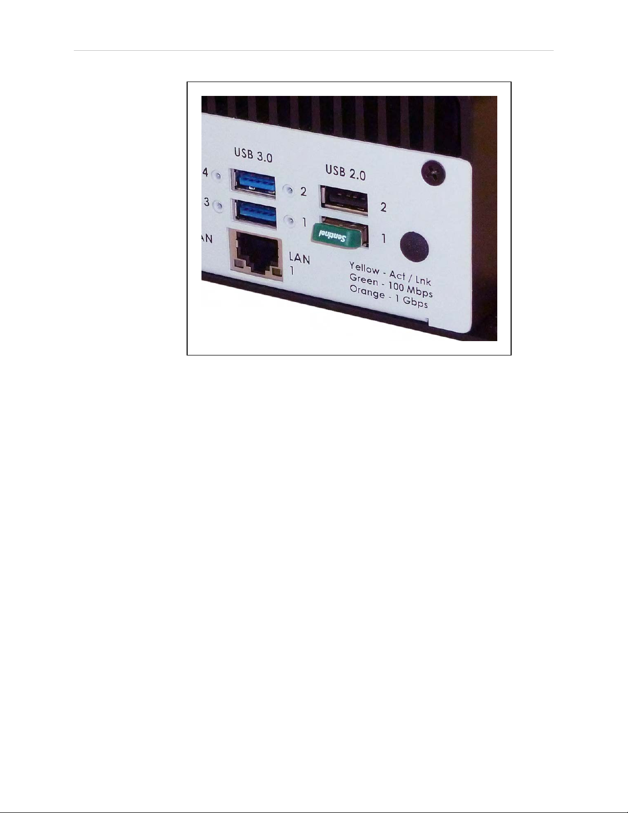
Chapter 1: Introduction
Figure 1-2. USB License Dongle in USB 2.0 Port 1
A SmartVision MX can support a total of eight cameras and four controllers.
Software
The following software is pre-loaded on the hard drive:
l
Windows®7 Embedded
l
ACE
l
ACE Sight 3 (ACE-based vision software)
l
Drivers for Basler ACEcameras (USB and GigE)
The SmartVision MX is designed to run ACE software. We do not support applications other
than ACE.
Options
For details on options, see Options on page 33.
l
Extended licenses, enabled on the USB license dongle
l
Stack-mounting brackets
14362-000 Rev. D SmartVision MX User'sGuide 9
Page 10
1.2 How Can I Get Help?
What Doesn’t Come with a SmartVision MX?
l 24 VDC power supply to power the SmartVision MXindustrial PC (see External Power
Supply on page 18).
l
Cameras and camera cables
l
Keyboard, mouse, and monitor
These should be user-supplied, so you can run the ACE and ACESight applications,
and well as control shutting down the industrial PC.
l
If power interruption is a concern, a UPS is recommended (see External Power Supply
on page 18).
1.2 How Can I Get Help?
For details on getting assistance with your software or hardware, you can access the corporate
website:
http://www.ia.omron.com
Related Manuals
This manual covers the installation and use of a SmartVision MX. The following manuals
provide information on safety, related products, advanced configurations and system specifications.
Table 1-1. Related Manuals
Manual Title Description
Robot Safety Guide Contains safety information for our robots.
ACE User’s Guide Instruction for the use of the ACE software.
ACESight User’s Guide Instruction for the use of the ACESight software.
SmartController EX User's
Guide
Contains information on the installation and operation of the
optional SmartController EXand sDIO products.
10 SmartVision MX User'sGuide 14362-000 Rev. D
Page 11
2.1 Dangers, Warnings, and Cautions
!
!
!
!
There are three levels of alert notation used in our manuals. In descending order of importance, they are:
DANGER: Identifies an imminently hazardous situation which, if not
avoided, is likely to result in serious injury, and might result in fatality or
severe property damage.
WARNING: Identifies a potentially hazardous situation which, if not avoided,
will result in minor or moderate injury, and might result in serious injury, fatality, or significant property damage.
CAUTION: Identifies a potentially hazardous situation which, if not avoided,
might result in minor injury, moderate injury, or property damage.
Chapter 2: Safety
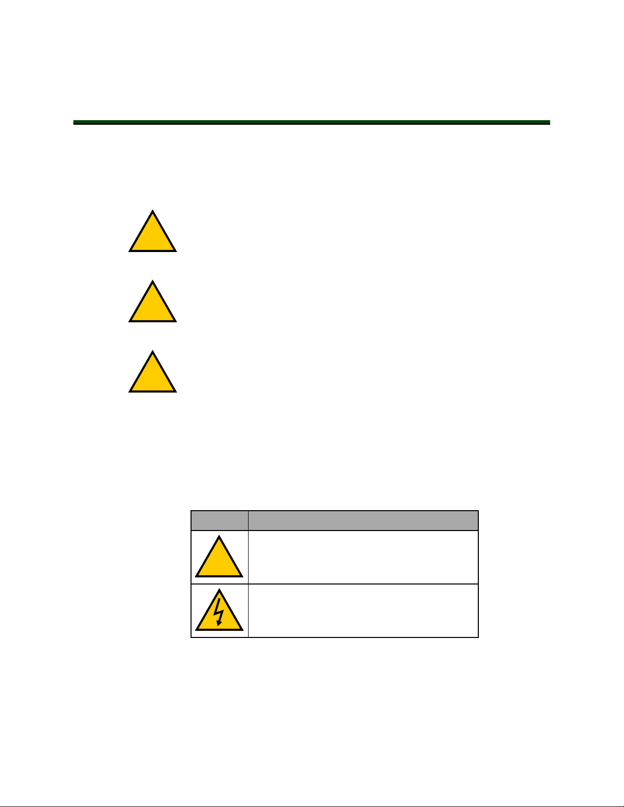
Alert Icons
The icon that starts each alert can be used to indicate the type of hazard. These will be used
with the appropriate signal word - Danger, Warning, or Caution - to indicate the severity of the
hazard. The text following the signal word will specify what the risk is, and how to avoid it.
Table 2-1. Alert Icon Meaning
Icon Meaning
This is a generic alert icon. Any specifics on the
risk will be in the text following the signal word.
This identifies a hazardous electrical situation.
14362-000 Rev. D SmartVision MX User'sGuide 11
Page 12

2.2 What to Do in an Emergency / Abnormal Situation
!
Special Information
There are several types of notation used to call out special information.
IMPORTANT: Information to ensure safe use of the product.
NOTE: Information for more effective use of the product.
Additional Information: Offers helpful tips, recommendations, and best prac-
tices.
Version Information: Information on differences in specifications for different
versions of hardware or software.
2.2 What to Do in an Emergency / Abnormal Situation
Stopping the Robot
Press any E-Stop button (a red push-button on a yellow background) and then follow the
internal procedures of your company or organization for an emergency situation.
Fire Response
If a fire occurs, use CO2to extinguish the fire.
2.3 Safety Precautions
WARNING: ELECTROCUTIONRISK
During maintenance, disconnect AC power from the robot, and install a lockout tag-out to prevent anyone from reconnecting power.
WARNING: PERSONALINJURYORPROPERTYDAMAGERISK
A robot can cause serious injury or death, or damage to itself and other equipment, if the safety precautions in this manual are not observed:
l
All personnel who install, operate, teach, program, or maintain the system must read
this guide, read the Robot Safety Guide, and complete a training course for their responsibilities in regard to the robot.
Figure 2-1. Read Manual and Impact Warning Labels
12 SmartVision MX User'sGuide 14362-000 Rev. D
Page 13

l
All personnel who design the robot system must read this guide, read the Robot Safety
Guide, and must comply with all local and national safety regulations for the location in
which the robot is installed.
l
The robot system must not be used for purposes other than described in the robot user’s
guide. Contact your local Omron support if you are not sure of the suitability for your
application.
l
The user is responsible for providing safety barriers around the robot to prevent anyone
from accidentally coming into contact with the robot when it is in motion.
l
Power to the robot and its power supply must be locked out and tagged out before any
maintenance is performed.
2.4 Additional Safety Information
We provide other sources for more safety information:
Manufacturer’s Declarations
This lists the standards with which our robots and controllers comply. The Manufacturer’s
Declarations are in the Manufacturer's Declarations Guide.
Chapter 2: Safety
Robot Safety Guide
The Robot Safety Guide provides detailed information on safety for our robots. It also gives
resources for more information on relevant standards. It ships with each robot.
2.5 Disposal
Customers can contribute to resource conservation and protecting the environment by the
proper disposal of WEEE (Waste Electronics and Electrical Equipment). All electrical and electronic products should be disposed of separately from the municipal waste system via designated collection facilities. For information about disposal of your old equipment, Contact
your local Omron support.
Dispose of in accordance with applicable regulations.
14362-000 Rev. D SmartVision MX User'sGuide 13
Page 14

Page 15

The SmartVision MX should be shipped and stored in the supplied packaging, which is
designed to prevent damage from normal shock and vibration. You should protect the package
from excessive shock and vibration. For environmental specifications, refer to Environmental
Specifications on page 29.
3.1 Inspecting
Carefully inspect all packaging for evidence of damage during transit. If any damage is indicated, request that the carrier’s agent be present at the time the package is opened.
Compare the actual items received (not just the packing slip) with your equipment purchase
order, and verify that all items are present and that the shipment is correct. Inspect each item
for external damage as it is unpacked. Contact your local Omron support immediately if any
damage is evident. See “How Can I Get Help?” section on page 15.
Retain all containers and packaging materials. These items may be needed in the future to
settle a damage claim.
Remove the SmartVision MX. Mount it near the robot.
3.2 Transport and Storage
Chapter 3: Installation
The SmartVision MX must be shipped and stored in a temperature-controlled environment,
within the range -25 to 60°C (-13 to 140°F). The recommended humidity range is 5 to 90%,
non-condensing.
It must always be stored and shipped in a clean, dry area that is free from condensation.
3.3 Mounting the SmartVision MX
NOTE: The SmartVision MX is not intended for use in hazardous environments
(explosive gas, water, dust, oil mist) or in the presence of ionizing or non-ionizing radiation.
The base of the industrial PC has four tabs with holes for screwing it to a flat surface. These
are also used when mounting to a SmartController with the optional stack-mount brackets.
Regardless of the mounting method used, allow adequate space around the unit for air circulation.
14362-000 Rev. D SmartVision MX User'sGuide 15
Page 16
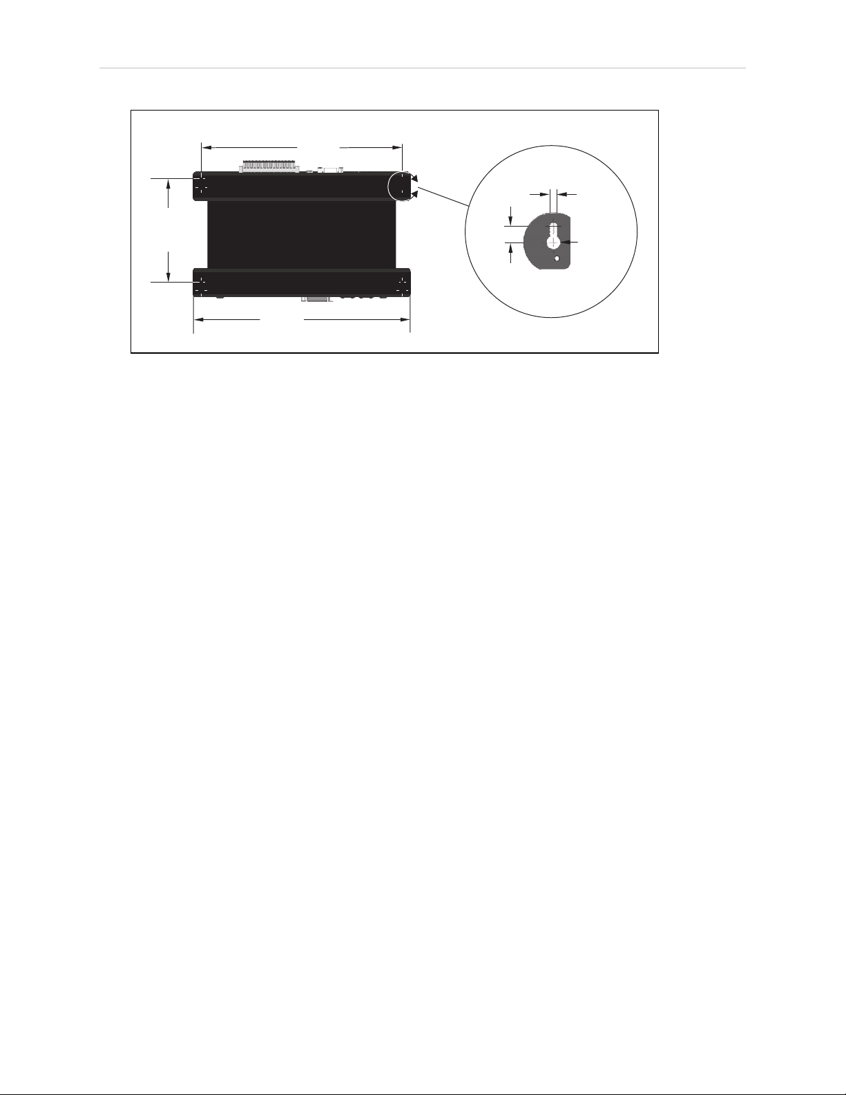
3.3 Mounting the SmartVision MX
124.0
(4.9)
240.0
(9.5)
260
(10.2)
4.25
(0.17)
10.0
(0.39)
R4.0
(0.16)
Figure 3-1. Dimensions for Mounting (Units in mm)
Vertical Mounting
Vertical mounting against a cabinet wall using the four bottom tabs is the recommended
mounting method.
Use 6-32 UNC screws, or screws of similar specifications, for mounting the processor to a vertical surface. The screw length is determined by the surface being mounted to.
Desk-top Mounting
Use 6-32 UNC screws, or screws of similar specifications, for mounting the processor to a flat
surface. The screw length is determined by the surface being mounted to.
Stack Mounting
The SmartVision MX industrial PC can be stack-mounted on top of a SmartController, if there
is one in the system, using two mounting brackets (14393-000) available as an option with the
industrial PC. Refer to Chapter 7: Options for more information.
Views of the bracket are shown in the following figure.
16 SmartVision MX User'sGuide 14362-000 Rev. D
Page 17

Chapter 3: Installation
14393-000
Figure 3-2. Views of SmartVision MX-SmartController Mounting Bracket
The mounting brackets are strictly a mechanical attachment. No electrical connections are
involved.
1.
Screw one bracket to each end of the SmartController motion controller.
Use four of each of these connectors for each bracket:
l
M3x10 stainless socket-head cap screws
l
M3 high-collar split lock washers
l
M3 stainless flat washers
Tighten the M3 screws to 1.2 N·m (10.6 in-lbf).
There are two sets of two threaded holes on each side of the ventilation holes on the
sides of the SmartController case. See the following figure.
2.
Screw the SmartVision MX industrial PC to the top of the brackets, using the mounting
tabs on the bottom of the SmartVision MX.
The SmartVision MX tabs go on top of the brackets.
14362-000 Rev. D SmartVision MX User'sGuide 17
Page 18

3.4 Connecting Power
!
Use two of each of these connectors at each bracket:
l
M4x8 stainless socket-head cap screws
l
M4 stainless split lock washers
l
M4 stainless flat washers
Tighten the M4 screws to 4.6 N·m (40.7 in-lbf).
3.4 Connecting Power
Connect 24 VDC power to the input of the SmartVision MX.
External Power Supply
The SmartVision MX requires filtered 24 VDC power. It takes 4.2 A at 24 VDC.
NOTE: You must provide your own power supply. Make sure the power cables
and power supply conform to the specifications in the following table.
Table 3-1. Power Supply andPower Cable Specifications
Customer-Supplied
Power Supply
Circuit Protection Not more than 8 A (below the amper-
Power Cabling 1.5 to 1.85 mm2(16 to 14 AWG), full-
Shield Termination Braided shield connected to the left
CAUTION: Make sure you select a 24 VDC power supply that meets the specifications in the preceding table. Using an underrated supply can cause system problems and prevent your equipment from operating correctly. See the
following table for recommended power supplies.
NOTE: The power requirements for the user-supplied power supply will vary
depending on the configuration of the SmartVision MX industrial PC and connected devices. A minimum configuration requires 3.0 A at 24 VDC. However, a
24 V, 6 A power supply is recommended to allow for additional current draw
from connected external devices.
24 VDC (-10%, +5%), 150 W (6 A)
age rating of the cable used)
cover, braided shield cable, maximum
length 10 meters
wire slot of the VDC connector on the
power side of the SmartVision MX. On
the other end of the cable, the shield
should be connected to the power supply chassis.
18 SmartVision MX User'sGuide 14362-000 Rev. D
Page 19

Chapter 3: Installation
Recommended Power Supplies
Table 3-2. Recommended Power Supplies
Vendor Name Model Ratings Mount
OMRON S8FS-G15024C 24 VDC, 6.5 A, 150 W Side/Bottom
OMRON S8FS-G15024CD 24 VDC, 6.5 A, 150 W DIN-Rail Mount
Recommended UPS Units
If power interruption is a concern, a UPS is recommended. The following table lists two recommended UPS units.
Table 3-3. Recommended UPSUnits
Vendor Name Model Ratings
OMRON S8BA-24D24D360LF 24 VDC, 15 A, 360 W
OMRON S8BA-24D24D480LF 24 VDC, 20 A, 480 W
Installing 24 VDC Connector
In order to maintain compliance with EN standards, DC power must be delivered over a shielded cable, with the shield connected to the frame ground at both ends of the cable. Conductors
should be 1.5 to 1.85 mm2(16 to 14 AWG). The maximum length for the 24 VDC cable is 10
meters.
Use the supplied connector to connect the user-supplied 24 VDC power supply to the SmartVision MX.
1.
Locate the 24 VDC connector that is shipped with the SmartVision MX industrial PC.
See the following figure.
2.
Strip 7 mm of insulation from the end of the wire that connects to the positive output of
the 24 VDC supply.
3.
Insert the stripped end of the wire into the opening on the right side of the connector.
4.
Using a small, flat-blade screwdriver, tighten the screw clamp on the connector.
5.
Inspect the connection to ensure that the clamp is on the wire, not on the insulation.
6.
Gently pull on the wire to confirm that it is securely attached to the connector.
7.
Repeat this process to connect the wire from the negative side of the power supply to
the center of the connector.
8.
Repeat this process to connect the braided shield to the left side of the connector.
9.
Plug the connector into the SmartVision MX industrial PC.
14362-000 Rev. D SmartVision MX User'sGuide 19
Page 20

3.4 Connecting Power
-
+
-
+
SmartV
ision MX
24 VDC, 6A
1
2
6
5
4
3
Figure 3-3. DC Connector with Wires
Figure 3-4. Ground for 24 VDC Cable Connections
Table 3-4. 24 VDCCableConnection Descriptions
Item Description
1 Attach shield from user-supplied cable to SmartVision MX using left wire slot in 24
VDC connector.
2 Use connector supplied at this end of cable.
3 Optional fuse.
4 Frame ground.
5 Attach shield from user-supplied cable to frame ground on power supply.
6 User-supplied power supply, circuit protection < 8 A.
Connecting to a SmartController
The 24 VDC power cable is user-supplied.
1.
Connect a 24 VDC cable from XDC1 or XDC2 on the controller (whichever is not used)
to the 24 VDC connector on the SmartVision MX industrial PC.
20 SmartVision MX User'sGuide 14362-000 Rev. D
Page 21

2.
Follow the instructions in the previous section for connecting VDC to the SmartVision
MX industrial PC.
If your system has sDIO or sMI6, these need to be placed between the SmartController and the
SmartVision MX industrial PC, so the power can be daisy-chained. The SmartVision MX
industrial PC has only one 24 VDC plug. The other units have two.
If you are connecting peripherals to the SmartVision MX industrial PC, you may need to run a
dedicated 24 VDC cable to the SmartVision MX industrial PC, rather than tapping power from
the controller or your power supply. Make sure you are not exceeding the current capacity of
the controller 24 VDC plug.
3.5 Connecting Display, Keyboard, and Mouse
To connect a display to the SmartVision MX industrial PC, use either of the DVI- ports. If you
have a VGA display, you will need to use the DVI-I port with a VGA adapter.
Connect your keyboard and mouse to USB ports.
Chapter 3: Installation
14362-000 Rev. D SmartVision MX User'sGuide 21
Page 22

Page 23

Chapter 4: Connectors and Indicators
1
6
5
4
3
2
The SmartVision MX, as shown in the following figures, can connect to many different peripherals. This section describes the connectors and indicators available.
Camera Side
Figure 4-1. SmartVision MX Camera-side Connectors
Table 4-1. SmartVision MX Camera-side Connector Descriptions
Item Quantity Description
1 4 Gigabit Ethernet ports with Power Over Ethernet Ports
(15.4 W max per port)
2 1 DVI-DOutput Port
3 1 DVI-IOutput Port
4 4 USB 3.0 Ports
5 2 Gigabit Ethernet Ports
6 2 USB2.0 Ports
14362-000 Rev. D SmartVision MX User'sGuide 23
Page 24

Power/IO Side
1
2
9
8
7
6
5
4
3
Item Description
1 Power Button
2 Not Supported
3 Not Supported
Figure 4-2. SmartVision MX Power-side Connectors
Table 4-2. SmartVision MX Power-side Connector Descriptions
4 Audio In / Out Ports (not used by software)
5 RS232 / RS485 Port
6 RS232 Port
7 Power InputConnector (9 to 36 VDC nominal, 4.2 A @ 24 VDC)
8 HDDLED
9 Power ONLED
24 SmartVision MX User'sGuide 14362-000 Rev. D
Page 25

4.1 Ethernet Ports
!
Any of the Ethernet ports can be used to connect to Ethernet devices. Four of the ports provide
Power over Ethernet, intended to provide the power needed for a GigE camera, though they
can also be used as general-purpose Ethernet ports.
To attach the industrial PC to a network or broadband device, connect an Ethernet cable
between the device and one of the Ethernet ports on the industrial PC.
CAUTION: It is not recommended that you connect the SmartVision MX directly to the internet for security reasons. If the industrial PC is directly exposed
to the network, it could become vulnerable if not managed properly. If the
SmartVision MX is on a LAN that has Internet access, make sure there is a firewall between the LAN and the Internet in order to prevent unwanted and unauthorized network traffic from reaching the SmartVision MX.
We recommend that you use Category 5 or better wiring and connectors for your network.
NOTE: If you are using a camera with a USB 2.0 connector or with an Ethernet
connector that is not designed for PoE, you will need to provide DC power to the
camera through a separate cable.
Chapter 4: Connectors and Indicators
4.2 USB Ports
For a USB3.0 camera, use one of the USB 3.0 ports.
To attach a USB peripheral, plug the peripheral cable into any one of the USB ports on the
SmartVision MX industrial PC.
NOTE: The bottom-right USB 2.0 port is used for the license dongle, which is
needed for the industrial PC to function. Do not remove the dongle.
4.3 DVI- Ports
To connect a monitor with a DVI connector:
l
Connect the monitor to the DVI-I port on the SmartVision MX
or
l
Connect the monitor to the DVI-D port on the SmartVision MX.
Connecting a VGA monitor requires using the DVI-I port with a user-supplied VGA adapter.
4.4 Audio and Serial Ports
The Audio In, Audio Out, and the two RS232(/485) ports are fully functional, but are not used
for vision processing.
14362-000 Rev. D SmartVision MX User'sGuide 25
Page 26

Page 27

Chapter 5: Operation
This chapter describes how to operate the SmartVision MX. Before proceeding, you need to
have performed the steps covered in the Installation chapter.
5.1 Operating Environment
l
Ambient operating temperature: 0 to 50°C (32 to 122°F)
l
Operating humidity: 10 to 90% (non-condensing)
5.2 Turning Power ON and OFF
The power button is a toggle. If the processor is on, pressing the button will turn it off. If the
processor is off, pressing the button will turn it on.
The power button is on the power side of the processor, where 24 VDC is connected. When
power is on, the ON LED will be lit.
5.3 Checking the Licenses on the Dongle
You can see what has been enabled on a dongle with the following procedure:
1.
Turn on the SmartVision MX industrial PC and wait for it to finish booting.
2.
Double-click the ACE icon on the desktop.
3.
Select Create Example Workspace, then click Open.
4.
Click Help > Diagnostic Summary.
ACE will display a list of all options that can be licensed by the dongle, and indicate
which ones have been enabled.
14362-000 Rev. D SmartVision MX User'sGuide 27
Page 28

Page 29

Chapter 6: Technical Specifications
6.1 Processor Specifications
Table 6-1. Processor Specifications
CPU Intel®Core i7
PCH Intel®HM76 Platform Controller Hub
Memory 8 GB DDR3
Operating System Microsoft®Windows®Embedded Standard 7, 64
Hard Drive 64 GB SSD
6.2 Environmental Specifications
The SmartVision MX must be shipped and stored in a temperature-controlled environment.
Refer to the following table.
Table 6-2. Environmental Specifications
bit
Ambient temperature 0 to 50°C (32 to 122°F)
Storage and shipment temperature –25 to 55°C (-13 to 131°F)
Humidity range 10 to 90%, non-condensing
6.3 Power Requirements
Power Input 24 (-10%, +5%) VDC
Typical Power Consumption 4.2 A
Maximum Power Consumption 6.0 A at 24 VDC
Circuit Protection Not more than 8 A
Table 6-3. Power Specifications
14362-000 Rev. D SmartVision MX User'sGuide 29
Page 30

6.4 Dimensions
225
150
260
162
328.9
225
52
186.5
15 150
6.4 Dimensions
Width, including tabs 260 mm (10.24 inches)
Width, without tabs 225 mm (8.86 inches)
Depth, excluding connectors 150 mm (5.9 inches)
Height 68.1 mm (2.68 inches)
Table 6-4. SmartVision MX Dimensions
Figure 6-1. SmartVision MX Dimensions (Units in mm)
Figure 6-2. SmartVision MX Stack Mounted to SmartController EX (Units in mm)
30 SmartVision MX User'sGuide 14362-000 Rev. D
Page 31

6.5 Connections
l
10/100/1000 Ethernet x 6
4 are PoE, up to 15.4 W/port
l
USB 3.0 x 4
l
USB 2.0 x 2
One of these is used for the license dongle.
l
DVI-D output
l
DVI-I output
l
RS232/RS485 port
l
RS232 port
l
Digital I/O (not supported)
Chapter 6: Technical Specifications
14362-000 Rev. D SmartVision MX User'sGuide 31
Page 32

6.6 Camera Specifications
6.6 Camera Specifications
The following table provides specifications for camera variations that are compatible with the
SmartVision MX.
Table 6-5. Camera Variations
Model
Image
Elements
Effective
Pixels (H x V)
Color / Monochrome
Frame Rate 120 fps 30 fps 30 fps 60 fps 60 fps 25 fps 25 fps
Trigger input Software / External Software Software / External
Interface Gigabit Ethernet (1 Gbit/s)
Lens Mounting
Power Supply
Voltage
Power Consumption
(PoE / AUX)
24114-
101
1/4-inch
CCD
658 x
492
Color Mono-
C mount / CSmount C mount C mount /
PoEor 12 VDC
2.5 W /
2.0 W
24114-
200
1/3-inch
CCD
1296 x
966
chrome
2.7 W / 2.2 W 2.7 W / 2.1 W 3.1 W / 2.6 W
24114-
201
1/3-inch
CCD
1294 x
964
Color Mono-
24114-
250
1/1.8inch
CMOS
1602 x
1202
chrome
24114-
251
1/1.8inch
CMOS
1600 x
1200
Color Mono-
CSmount
24114-
300
1-inch
CMOS
2048 x
2048
chrome
C mount
24114-
1-inch
CMOS
2046 ×
2046
Color
301
Weight Approximately 90 g
Bundeled
Cables
Camera Cable, 10 m (14359-000)
Power I/O Cable, 10 m (09454-610)
32 SmartVision MX User'sGuide 14362-000 Rev. D
Page 33

7.1 License Options
There are several different license requirements that are based on the software type and ACE
version. Use the table below to understand the different software license compatibility options.
Refer to Chapter 1: Introduction for USB license dongle information.
Software License Details
Chapter 7: Options
Table 7-1. Software License Compatibility
Software Licensing for ACE 3.6 or
Earlier
ACEPackXpert with
AdeptSight
ACEPackXpert License Required License Required
AdeptSight 3.0 License Required License Required
Additional Camera
(standard)
Additional Camera
(color)
ACE Controller License Required Not Applicable
OPCServer License Required Not Applicable
OPCClient License Required Not Applicable
UIBuilder Option License Required Not Applicable
Emulator Not Applicable Not Applicable
Includes ACEPackXpert and
AdeptSight 3.0
License Required Not Applicable
License Required Not Applicable
Licensing for ACE 3.7.3.200 or
Later
Includes ACEPackXpert and
AdeptSight 3.0
7.2 Mounting Options
The SmartVision MX industrial PC can be ordered with brackets that let the user mount the
industrial PC on top of a SmartController motion controller.
Mounting Kits
The following mounting kit is available (order separately).
14362-000 Rev. D SmartVision MX User'sGuide 33
Page 34

7.2 Mounting Options
Table 7-2. Mounting Kit Details
Item Part Number Contents
Mounting Bracket Kit 14391-000 l Bracket: 2 x 14393-000
l M4 flat washer: 4 x 54000-96700
l M4 lock washer:4 x 54100-96700
l M4x8 screw: 4 x 09664-008
l M3 lock washer: 8 x 00782-000
l M3x10 screw: 8 x 51020-65010
l M3 flat washer: 8 x 54000-96500
34 SmartVision MX User'sGuide 14362-000 Rev. D
Page 35

Page 36

OMRON Corporation Industrial Automation Company
Kyoto, JAPAN
Regional Headquarters
OMRON EUROPE B.V.
Wegalaan 67-69, 2132 JD Hoofddorp
The Netherlands
Tel: (31)2356-81-300/Fax: (31)2356-81-388
OMRON ASIA PACIFIC PTE. LTD.
No. 438A Alexandra Road # 05-05/08 (Lobby 2),
Alexandra Technopark,
Singapore 119967
Tel: (65) 6835-3011/Fax: (65) 6835-2711
Contact: industrial.omron.eu
OMRON ELECTRONICS LLC
2895 Greenspoint Parkway, Suite 200 Hoffman Estates,
IL 60169 U.S.A.
Tel: (1) 847-843-7900/Fax: (1) 847-843-7787
OMRON ADEPT TECHNOLOGIES, INC.
4550 Norris Canyon R oad, Suite 150, San Ramon, CA 94583 U.S.A.
Tel: (1) 925-245-3400/Fax: (1) 925-960-0590
OMRON (CHINA) CO., LTD.
Room 2211, Bank of China Tower, 200 Yin Cheng Zhong Road,
PuDong New Area, Shanghai, 200120, China
Tel: (86) 21-5037-2222/Fax: (86) 21-5037-2200
Authorized Distributor:
© OMRON Corporation 2019 All Rights Reserved.
In the interest of product improvement,
specifications are subject to change without notice.
Cat. No. I608-E-03
Printed in USA
0319 (0416)
14362-000 D
 Loading...