

Page 1
Cat. No. V104-E1-04
NV Series
NV3W
NV4W
NV3Q
Programmable Terminals
PROGRAMMING MANUAL
Page 2

NV Series NV3W NV4W NV3Q
Programmable Terminals
Revised October 2011
Page 3

iv
Page 4

Notice
OMRON products are manufactured for use according to proper procedures by a qualified operator
and only for the purposes described in this manual.
The following conventions are used to indicate and classify precautions in this manual. Always heed
the information provided with them. Failure to heed precautions can result in injury to people or damage to property.
!DANGER Indicates an imminently hazardous situation which, if not avoided, will result in death or
serious injury. Additionally, there may be severe property damage.
!WARNING Indicates a potentially hazardous situation which, if not avoided, could result in death or
serious injury. Additionally, there may be severe property damage.
!Caution Indicates a potentially hazardous situation which, if not avoided, may result in minor or
moderate injury, or property damage.
OMRON Product References
All OMRON products are capitalized in this manual. The word “Unit” is also capitalized when it refers to
an OMRON product, regardless of whether or not it appears in the proper name of the product.
The abbreviation “Ch,” which appears in some displays and on some OMRON products, often means
“word” and is abbreviated “Wd” in documentation in this sense.
The abbreviation “PLC” means Programmable Controller.
The abbreviation “host” means a controller, such as an IBM PC/AT or compatible computer, that controls a PT (Programmable Terminal).
Visual Aids
The following headings appear in the left column of the manual to help you locate different types of
information.
Precautions
for Safe Use
Precautions
for Correct Use
CS1G-CPU@@-V1 Boxes in model numbers indicate variable characters. For example, “CS1G-CPU@@-
OMRON, 2009
All rights reserved. No part of this publication may be reproduced, stored in a retrieval system, or transmitted, in any form, or by any means,
mechanical, electronic, photocopying, recording, or otherwise, without the prior written permission of OMRON.
No patent liability is assumed with respect to the use of the information contained herein. Moreover, because OMRON is constantly striving
to improve its high-quality products, the information contained in this manual is subject to change without notice. Every precaution has been
taken in the preparation of this manual. Nevertheless, OMRON assumes no responsibility for errors or omissions. Neither is any liability
assumed for damages resulting from the use of the information contained in this publication.
Indicates precautions on handling the product to ensure that the product is used safely.
Indicates precautions to ensure that product functions and performances are realized, to
ensure that the reliability of the product is maintained, and to ensure that the product is
otherwise used correctly.
Note Indicates information of particular interest for efficient and convenient opera-
tion of the product.
Reference Indicates supplementary information on procedures, descriptions, and settings.
1,2,3... 1. Indicates lists of one sort or another, such as procedures, checklists, etc.
EV1” indicates the following models: CS1G-CPU42-EV1, CS1G-CPU43-EV1, CS1GCPU44-EV1, and CS1G-CPU45-EV1.
v
Page 5

vi
Page 6

TABLE OF CONTENTS
SECTION 1
Overview . . . . . . . . . . . . . . . . . . . . . . . . . . . . . . . . . . . . . . . . . 1
1-1 NV-Designer Features . . . . . . . . . . . . . . . . . . . . . . . . . . . . . . . . . . . . . . . . . . . . . . . . . . . . . . 2
1-2 System Versions. . . . . . . . . . . . . . . . . . . . . . . . . . . . . . . . . . . . . . . . . . . . . . . . . . . . . . . . . . . 4
SECTION 2
PT Internal Data Structure and Display Methods . . . . . . . 7
2-1 Internal Data Types and Structure . . . . . . . . . . . . . . . . . . . . . . . . . . . . . . . . . . . . . . . . . . . . . 8
2-2 Displaying Screens . . . . . . . . . . . . . . . . . . . . . . . . . . . . . . . . . . . . . . . . . . . . . . . . . . . . . . . . 11
2-3 Backlight Display Methods . . . . . . . . . . . . . . . . . . . . . . . . . . . . . . . . . . . . . . . . . . . . . . . . . . 14
SECTION 3
NV-Designer Outline and Configuration . . . . . . . . . . . . . . . 15
3-1 System Requirements . . . . . . . . . . . . . . . . . . . . . . . . . . . . . . . . . . . . . . . . . . . . . . . . . . . . . . 16
3-2 NV-Designer Window Names and Menus. . . . . . . . . . . . . . . . . . . . . . . . . . . . . . . . . . . . . . . 17
3-3 NV-Designer Configuration. . . . . . . . . . . . . . . . . . . . . . . . . . . . . . . . . . . . . . . . . . . . . . . . . . 29
SECTION 4
Overall Flow of NV-Designer Operation . . . . . . . . . . . . . . . 39
4-1 Overall Flow of Operation. . . . . . . . . . . . . . . . . . . . . . . . . . . . . . . . . . . . . . . . . . . . . . . . . . .40
4-2 Creating a Simple Screen. . . . . . . . . . . . . . . . . . . . . . . . . . . . . . . . . . . . . . . . . . . . . . . . . . . . 41
SECTION 5
Creating and Saving Projects (Including Screen Data) . . . 53
5-1 Starting the NV-Designer and Creating New Projects. . . . . . . . . . . . . . . . . . . . . . . . . . . . . . 54
5-2 Checking or Converting the Model . . . . . . . . . . . . . . . . . . . . . . . . . . . . . . . . . . . . . . . . . . . . 59
5-3 Creating Base Screens . . . . . . . . . . . . . . . . . . . . . . . . . . . . . . . . . . . . . . . . . . . . . . . . . . . . . . 61
5-4 Positioning Character Strings, Graphics, and Parts . . . . . . . . . . . . . . . . . . . . . . . . . . . . . . . . 62
5-5 Copying and Moving Parts and Screens . . . . . . . . . . . . . . . . . . . . . . . . . . . . . . . . . . . . . . . . 63
5-6 Saving the Project . . . . . . . . . . . . . . . . . . . . . . . . . . . . . . . . . . . . . . . . . . . . . . . . . . . . . . . . . 65
5-7 Project and Execution Files . . . . . . . . . . . . . . . . . . . . . . . . . . . . . . . . . . . . . . . . . . . . . . . . . .66
SECTION 6
NV Configuration . . . . . . . . . . . . . . . . . . . . . . . . . . . . . . . . . . 67
6-1 NV Configuration . . . . . . . . . . . . . . . . . . . . . . . . . . . . . . . . . . . . . . . . . . . . . . . . . . . . . . . . . 68
6-2 Setting the NV Configuration from the NV-Designer . . . . . . . . . . . . . . . . . . . . . . . . . . . . . . 72
vii
Page 7

TABLE OF CONTENTS
SECTION 7
Descriptions of Parts. . . . . . . . . . . . . . . . . . . . . . . . . . . . . . . . 93
7-1 Character Strings and Graphics (Fixed Parts) . . . . . . . . . . . . . . . . . . . . . . . . . . . . . . . . . . . . 95
7-2 Parts . . . . . . . . . . . . . . . . . . . . . . . . . . . . . . . . . . . . . . . . . . . . . . . . . . . . . . . . . . . . . . . . . . . . 99
7-3 Specifying Addresses. . . . . . . . . . . . . . . . . . . . . . . . . . . . . . . . . . . . . . . . . . . . . . . . . . . . . . . 115
7-4 Bit Switches (“Switch”). . . . . . . . . . . . . . . . . . . . . . . . . . . . . . . . . . . . . . . . . . . . . . . . . . . . . 119
7-5 Function Switches . . . . . . . . . . . . . . . . . . . . . . . . . . . . . . . . . . . . . . . . . . . . . . . . . . . . . . . . . 120
7-6 Lamps . . . . . . . . . . . . . . . . . . . . . . . . . . . . . . . . . . . . . . . . . . . . . . . . . . . . . . . . . . . . . . . . . . 122
7-7 Data Parts and Keyboard Parts . . . . . . . . . . . . . . . . . . . . . . . . . . . . . . . . . . . . . . . . . . . . . . . 123
7-8 Level Meters . . . . . . . . . . . . . . . . . . . . . . . . . . . . . . . . . . . . . . . . . . . . . . . . . . . . . . . . . . . . . 128
7-9 Clocks . . . . . . . . . . . . . . . . . . . . . . . . . . . . . . . . . . . . . . . . . . . . . . . . . . . . . . . . . . . . . . . . . . 131
7-10 Line Graphs . . . . . . . . . . . . . . . . . . . . . . . . . . . . . . . . . . . . . . . . . . . . . . . . . . . . . . . . . . . . . . 134
7-11 Alarm Lists (NV4W/NV3Q) . . . . . . . . . . . . . . . . . . . . . . . . . . . . . . . . . . . . . . . . . . . . . . . . . 144
7-12 Custom Parts . . . . . . . . . . . . . . . . . . . . . . . . . . . . . . . . . . . . . . . . . . . . . . . . . . . . . . . . . . . . . 156
7-13 Multifunction Objects . . . . . . . . . . . . . . . . . . . . . . . . . . . . . . . . . . . . . . . . . . . . . . . . . . . . . . 159
SECTION 8
Using PT Functions. . . . . . . . . . . . . . . . . . . . . . . . . . . . . . . . . 161
8-1 Switching Backlight Colors. . . . . . . . . . . . . . . . . . . . . . . . . . . . . . . . . . . . . . . . . . . . . . . . . .162
8-2 Repeated Copying . . . . . . . . . . . . . . . . . . . . . . . . . . . . . . . . . . . . . . . . . . . . . . . . . . . . . . . . . 164
8-3 Flow Display Data . . . . . . . . . . . . . . . . . . . . . . . . . . . . . . . . . . . . . . . . . . . . . . . . . . . . . . . . . 166
8-4 Write Address Data . . . . . . . . . . . . . . . . . . . . . . . . . . . . . . . . . . . . . . . . . . . . . . . . . . . . . . . . 169
8-5 Recipes. . . . . . . . . . . . . . . . . . . . . . . . . . . . . . . . . . . . . . . . . . . . . . . . . . . . . . . . . . . . . . . . . . 173
8-6 Security Functions . . . . . . . . . . . . . . . . . . . . . . . . . . . . . . . . . . . . . . . . . . . . . . . . . . . . . . . . . 180
8-7 Switching the Display Language. . . . . . . . . . . . . . . . . . . . . . . . . . . . . . . . . . . . . . . . . . . . . . 187
8-8 Displaying Resource Reports . . . . . . . . . . . . . . . . . . . . . . . . . . . . . . . . . . . . . . . . . . . . . . . . 190
8-9 Base Screen Memory Usage . . . . . . . . . . . . . . . . . . . . . . . . . . . . . . . . . . . . . . . . . . . . . . . . . 191
SECTION 9
Transferring Screens . . . . . . . . . . . . . . . . . . . . . . . . . . . . . . . 193
9-1 Transferring Screens from the NV-Designer. . . . . . . . . . . . . . . . . . . . . . . . . . . . . . . . . . . . . 194
9-2 Transferring and Copying Data Using SD Memory Cards (NV4W/NV3Q). . . . . . . . . . . . . 198
Appendices
A NV Memory Editor . . . . . . . . . . . . . . . . . . . . . . . . . . . . . . . . . . . . . . . . . . . . . . . . . . . . . . . .203
Index. . . . . . . . . . . . . . . . . . . . . . . . . . . . . . . . . . . . . . . . . . . . . 207
Revision History . . . . . . . . . . . . . . . . . . . . . . . . . . . . . . . . . . . 211
viii
Page 8

About this Manual
This manual describes how to create screens for and maintain the NV-series PTs using the NVDesigner and includes the sections described below.
Please read this manual carefully and be sure you understand the information provided before
attempting to use the NV-Designer. Be sure to read the precautions provided in the following section.
Precautions
This section provides general precautions for using the NV-series PTs and related devices.
Section 1 Overview
This section introduces the features and functions of the NV-Designer.
Section 2 PT Internal Data Structure and Display Methods
This section describes the internal data structure of an NV-series PT, how to control the screens displayed on the PT, and how to control the backlight.
Section 3 NV-Designer Outline and Configuration
This section gives the system requirements for running the NV-Designer, describes the windows and
menus of the NV-Designer, and explains the parameters in the NV-Designer Configuration.
Section 4 Overall Flow of NV-Designer Operation
This section describes the overall procedure for using the NV-Designer to set up an NV-series PT for
operation.
Section 5 Creating and Saving Projects (Including Screen Data)
This section describes how to create, save, and manipulate projects for NV-series PTs, including
operations that can be performed between projects.
Section 6 NV Configuration
This section describes the parameters in the NV Configuration in detail.
Section 7 Descriptions of Parts
This section describes how to create screens using the various parts provided by the NV-Designer.
Section 8 Using PT Functions
This section describes special functions that can be used with NV-series PTs and the NV-Designer.
Section 9 Transferring Screens
This section describes how to transfer screens to and from an NV-series PT using both communications and SD memory cards.
Appendix
The appendix describes how to use the NV Memory Editor, which allow you to edit the internal memory of the PT from the NV-Designer.
ix
Page 9

x
Page 10

Related Manuals
The following manuals are used for NV-series PTs. (The boxes at the end of the catalog
numbers indicate the revision code.)
This
Manual
NV-series PT Programming Manual......................... V104-E1-@
This manual describes the software functionality of NV-series PTs, how to install the NVDesigner, and the features of the NV-Designer.
For more information on NV-Designer operating procedures, refer to the online help in the
NV-Designer.
NV-series PT Setup Manual ..................................... V103-E1-@
This manual describes how to connect an NV-series PT to an OMRON PLC, features and
specifications, methods to set up communications and operation, and procedures for
maintenance and troubleshooting.
Refer to the NV-series PT Programming Manual (V104-E1-@) for more information on PT
functions and specific operating procedures.
NV-series PT Host Connection Manual.................... V105-E1-@
This manual describes how to connect an NV-series PT to a PLC produced by a manufacturer other than OMRON, including PLC memory area designations, communications settings, and connection methods.
xi
Page 11

Terminology
The following terminology is used in this manual.
PT In this manual, indicates an NV-series Programmable Terminal.
NV Series Indicates products in the OMRON NV Series of Programmable Terminals.
PLC Indicates a Programmable Controller in the OMRON SYSMAC CS/CJ/CP,
C, or CVM1/CV Series of Programmable Controllers.
CPU Unit Indicates a CPU Unit in the OMRON SYSMAC CS/CJ/CP, C, or CVM1/CV
Series of Programmable Controllers.
NV-Designer Indicates the OMRON NV-Designer.
Host Indicates the PLC, IBM PC/AT or compatible computer, or personal com-
puter functioning as the control device and interfaced with the NV-series PT.
xii
Page 12

Introduction
● Intended Audience
This manual is intended for the following personnel, who must also have knowledge of
electrical systems (an electrical engineer or the equivalent).
• Personnel in charge of introducing FA systems into production facilities.
• Personnel in charge of designing FA systems.
• Personnel in charge of installing and connecting FA systems.
• Personnel in charge of managing FA systems and facilities.
● General Precautions
• The user must operate the product according to the performance specifications
described in the operation manuals.
• Do not use the PT touch switch input functions for applications where danger to
human life or serious property damage is possible, or for emergency switch applications.
• Before using the product under conditions which are not described in the manual or
applying the product to nuclear control systems, railroad systems, aviation systems,
vehicles, combustion systems, medical equipment, amusement machines, safety
equipment, and other systems, machines and equipment that may have a serious
influence on lives and property if used improperly, consult your OMRON representative.
• Make sure that the ratings and performance characteristics of the product are sufficient for the systems, machines, and equipment, and be sure to provide the systems,
machines, and equipment with double safety mechanisms.
• This manual provides information for connecting and setting up an NV-series PT. Be
sure to read this manual before attempting to use the PT and keep this manual close
at hand for reference during installation and operation.
xiii
Page 13
Safety Precautions
Notation Used for Safety Information
The following notation is used in this manual to provide precautions required to ensure
safe usage of the product.
The safety precautions that are provided are extremely important to safety.
Always read and heed the information provided in all safety precautions.
The following notation is used.
Definition of Precautionary Information
!WARNING
Symbols
Indicates a potentially hazardous situation which, if not avoided, will
result in minor or moderate injury, or may result in serious injury or
death. Additionally there may be significant property damage.
Prohibition
Indicates a general prohibition.
Caution
Indicates general cautionary, warning, or danger level information.
!WAR NING
Always ensure that the personnel in charge confirm that installation,
inspection, and maintenance were properly performed for the PT. “Personnel in charge” refers to individuals qualified and responsible for
ensuring safety during machine design, installation, operation, maintenance, and disposal.
Ensure that installation and post-installation checks are performed by
personnel in charge who possess a thorough understanding of the
machinery to be installed.
Do not use the input functions of the PT, such as the function switches
or switches on the touch panel, in applications that involve human life,
in applications that may result in serious injury, or for emergency stop
switches.
Do not attempt to disassemble, repair, or modify the PT. Doing so may
impair the safety functions.
Do not attempt to take the Unit apart and do not touch any internal
parts while the power is being supplied. Doing either of these may
result in electrical shock.
The PT uses an analog touch panel. Never press more than two points
on the panel at a time. Otherwise, it may activate a switch somewhere
between the two points.
xiv
Page 14
Precautions for Safe Use
1. When unpacking the Units, check carefully for any external scratches or other damage.
Also, shake the Units gently and check for any abnormal sound.
2. The PT must be installed in a control panel.
3. The mounting panel must be between 1.6 and 4.8 mm thick. Tighten the Mounting
Brackets evenly to a torque of between 0.1 and 0.25 N·m for the NV3W/NV3Q and between 0.2 and 0.3 N·m for the NV4W to maintain water and dust resistance. Make sure
the panel is not dirty or warped and that it is strong enough to hold the Units.
4. Do not let metal particles enter the Units when preparing the panel.
5. Do not connect an AC power supply to the DC power terminals.
6. Do not perform a dielectric voltage test.
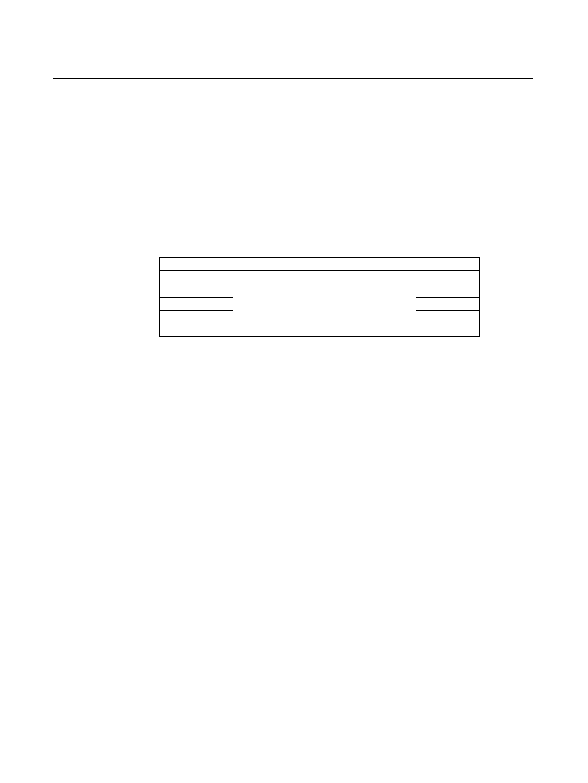
7. Use a DC power supply that will provide a stable output even if the input is momentarily
interrupted for 10 ms, and which has reinforced or double insulation.
Model Rated power supply voltage Capacity
NV3W-M@20L 5 VDC (allowable range: 4.5 to 5.5 VDC) 1 W min.
NV4W-M@@@ 24 VDC (allowable range: 21.6 to 26.4 VDC) 1.7 W min.
NV3W-M@@@ 2 W min.
NV3Q-MR@@ 2.4 W min.
NV3Q-SW@@ 3.6 W min.
8. Use a twisted-pair cable to connect to the power terminals. Tighten the terminal screws
to a torque of between 0.22 and 0.30 N·m. Make sure the screws are properly tightened.
9. To prevent malfunctions caused by noise, ground the PT correctly.
10. Do not touch the surface of the circuit boards or the components mounted on them with
your bare hands. Discharge any static electricity from your body before handling the
boards.
11. Turn OFF the power supply before connecting or disconnecting cables.
12. The maximum tensile load for cables is 30 N. Do not apply loads greater than this.
13. Confirm the safety of the system before turning ON or OFF the power supply.
14. Cycle the power supply after changing the DIP switch settings.
15. Do not perform the following operations while the SD memory card is being accessed
(NV4W/NV3Q only):
• Turning OFF the power supply to the PT
• Removing the memory card
Always follow the specified procedure when removing the memory card.
16. Start actual system application only after sufficiently checking screen data and the operation of the program in the PLC (host).
17. Do not press the touch switch with a force greater than 30 N.
18. Do not use a screwdriver or any other tool to press a touch switch.
19. Confirm the safety of the system before pressing any touch switch.
20. Do not accidentally press touch switches when the backlight is not lit or when the display does not appear. Confirm the safety of the system before pressing touch switches.
21. Before initializing screen data, confirm that existing data is backed up at the NV-Designer.
22. When changing the password with the system menu, do not reset or turn OFF the power supply until writing is finished.
xv
Page 15

23. Before using the SPMA function to change memory values in the PLC or transfer ladder
programming, confirm that the PT is operating. The SPMA function cannot be used unless the PT is operating.
24. Dispose of any battery that has been dropped on the floor or otherwise subjected to
excessive shock.
25. Dispose of the Units and batteries according to local ordinances as they apply.
26. When mounting the Battery, be sure to use the correct Battery and mount it correctly.
27. Do not disassemble or short-circuit the battery.
28. Do not connect a USB connector to any device that is not applicable.
29. Before connecting a USB connector to a device, make sure that the device is free of
damage.
30. Do not turn OFF the power supply to the PT while downloading or uploading screen
data or the system program. Doing so may corrupt the screen data or system program.
31. Periodically inspect the installation condition of the PT if it is being used in an environment subject to contact with water.
32. The whole system may stop depending on how the power supply is turned ON or OFF.
Turn ON or OFF the power supply according to the specified procedure.
33. Signals from the touch switches may not be input if the switches are pressed consecutively at high speed. Confirm each input before proceeding to the next one.
34. To use numeric input functions safely, always make maximum and minimum limit settings.
35. Do not use benzene, paint thinner, or other volatile solvents, and do not use chemically
treated cloths.
36. The PT uses an analog touch panel. Deterioration over time can cause the touch points
to move. Calibrate the touch panel if the touch points move too much.
37. Water resistance will be lost if the front sheet is torn or is peeling off. Do not use the PT
if the front sheet is torn or is peeling off.
38. The Rubber Packing will deteriorate, shrink, or harden depending on the operating environment. Inspect and replace the Rubber Packing periodically (approximately once
per year).
39. To use the NV3W in an environment with strong noise, connect the following noise filter
to the power supply line: RSEL-2001W manufactured by TDK-Lambda Corp.
40. A Waterproof Packing cannot be reused. To ensure waterproof performance, replace
the Waterproof Packing with a new one each time you reinstall the PT.
41. Screen burn-in will occur if the same pattern is continuously displayed for a long period
of time (24 hours or longer, as a guideline). To prevent screen burn-in, use a screen
saver or switch displays periodically (NV3W only).
xvi
Page 16

Precautions for Correct Use
1. Do not install the PT in any of the following locations.
• Locations subject to rapid changes in temperature
• Locations subject to temperatures or humidity outside the range specified in the specifications
• Locations subject to condensation as the result of high humidity
• Locations subject to splashing chemicals or solvents
• Locations subject to oil splashes
• Locations subject to continuous water splashing
• Locations subject to corrosive or flammable gases
• Locations subject to strong shock or vibration
• Locations outdoors subject to direct wind and rain
• Locations subject to strong ultraviolet light
• Locations subject to dust
• Locations subject to direct sunlight
2. Take appropriate and sufficient countermeasures when installing systems in the following locations.
• Locations subject to static electricity or other forms of noise
• Locations subject to strong electromagnetic or magnetic fields
• Locations close to power supply lines
• Locations subject to possible exposure to radioactivity
xvii
Page 17

Conformance to EC Directives
This product is EMC compliant.
● Concepts
OMRON products are electronic devices that are incorporated in machines and manufacturing installations. OMRON PTs conform to the related EMC Directives (see note) so that
the devices and machines into which they are built can more easily conform to EMC directives. However, customers may use a wide variety of equipment and manufacturing installations. Therefore the customer must check whether the Directives are satisfied for the
actual system. EMC-related performance will vary depending on the configuration, wiring,
and other conditions of the equipment or control panel in which the PT is installed. The
customer must, therefore, perform final checks to confirm that the overall machine or
device conforms to EMC standards.
Note The applicable EMC (Electromagnetic Compatibility) standards for NV-series
PTs are as follows:
NV3W: EN 61000-6-2, EN 61000-6-4
NV4W/NV3Q: EN 61131-2
● Conformance to EC Directives
NV-series PTs conform to EC Directives. To ensure that the machine or device in which
the NV-series PT is used complies with EC Directives, the PT must be installed as follows:
• The NV-series PT must be installed in a control panel.
• You must use reinforced insulation or double insulation for the DC power supply and
the DC power supply must have minimal voltage fluctuations and provide a stable output even if the power supply input is interrupted for 10 ms.
• NV-series PTs complying with EC Directives also conform to the Common Emission
Standard (EN 61131-2 or EN 61000-6-4). Radiated emission characteristics (10-m
regulations) may vary depending on the configuration of the control panel used, other
devices connected to the control panel, wiring, and other conditions. You must therefore confirm that the overall machine or equipment complies with EC Directives.
• This is a class A product. It may cause radio interference in residential areas, in which
case the user may be required to take adequate measures to reduce interference.
xviii
Page 18
Read and Understand this Manual
Please read and understand this manual before using the product. Please consult your OMRON
representative if you have any questions or comments.
Warranty and Limitations of Liability
WARRANTY
OMRON's exclusive warranty is that the products are free from defects in materials and workmanship for a
period of one year (or other period if specified) from date of sale by OMRON.
OMRON MAKES NO WARRANTY OR REPRESENTATION, EXPRESS OR IMPLIED, REGARDING NONINFRINGEMENT, MERCHANTABILITY, OR FITNESS FOR PARTICULAR PURPOSE OF THE
PRODUCTS. ANY BUYER OR USER ACKNOWLEDGES THAT THE BUYER OR USER ALONE HAS
DETERMINED THAT THE PRODUCTS WILL SUITABLY MEET THE REQUIREMENTS OF THEIR
INTENDED USE. OMRON DISCLAIMS ALL OTHER WARRANTIES, EXPRESS OR IMPLIED.
LIMITATIONS OF LIABILITY
OMRON SHALL NOT BE RESPONSIBLE FOR SPECIAL, INDIRECT, OR CONSEQUENTIAL DAMAGES,
LOSS OF PROFITS OR COMMERCIAL LOSS IN ANY WAY CONNECTED WITH THE PRODUCTS,
WHETHER SUCH CLAIM IS BASED ON CONTRACT, WARRANTY, NEGLIGENCE, OR STRICT
LIABILITY.
In no event shall the responsibility of OMRON for any act exceed the individual price of the product on which
liability is asserted.
IN NO EVENT SHALL OMRON BE RESPONSIBLE FOR WARRANTY, REPAIR, OR OTHER CLAIMS
REGARDING THE PRODUCTS UNLESS OMRON'S ANALYSIS CONFIRMS THAT THE PRODUCTS
WERE PROPERLY HANDLED, STORED, INSTALLED, AND MAINTAINED AND NOT SUBJECT TO
CONTAMINATION, ABUSE, MISUSE, OR INAPPROPRIATE MODIFICATION OR REPAIR.
xix
Page 19

Application Considerations
SUITABILITY FOR USE
OMRON shall not be responsible for conformity with any standards, codes, or regulations that apply to the
combination of products in the customer's application or use of the products.
At the customer's request, OMRON will provide applicable third party certification documents identifying
ratings and limitations of use that apply to the products. This information by itself is not sufficient for a
complete determination of the suitability of the products in combination with the end product, machine,
system, or other application or use.
The following are some examples of applications for which particular attention must be given. This is not
intended to be an exhaustive list of all possible uses of the products, nor is it intended to imply that the uses
listed may be suitable for the products:
• Outdoor use, uses involving potential chemical contamination or electrical interference, or conditions or
uses not described in this manual.
• Nuclear energy control systems, combustion systems, railroad systems, aviation systems, medical
equipment, amusement machines, vehicles, safety equipment, and installations subject to separate
industry or government regulations.
• Systems, machines, and equipment that could present a risk to life or property.
Please know and observe all prohibitions of use applicable to the products.
NEVER USE THE PRODUCTS FOR AN APPLICATION INVOLVING SERIOUS RISK TO LIFE OR
PROPERTY WITHOUT ENSURING THAT THE SYSTEM AS A WHOLE HAS BEEN DESIGNED TO
ADDRESS THE RISKS, AND THAT THE OMRON PRODUCTS ARE PROPERLY RATED AND
INSTALLED FOR THE INTENDED USE WITHIN THE OVERALL EQUIPMENT OR SYSTEM.
PROGRAMMABLE PRODUCTS
OMRON shall not be responsible for the user's programming of a programmable product, or any
consequence thereof.
xx
Page 20
Disclaimers
CHANGE IN SPECIFICATIONS
Product specifications and accessories may be changed at any time based on improvements and other
reasons.
It is our practice to change model numbers when published ratings or features are changed, or when
significant construction changes are made. However, some specifications of the products may be changed
without any notice. When in doubt, special model numbers may be assigned to fix or establish key
specifications for your application on your request. Please consult with your OMRON representative at any
time to confirm actual specifications of purchased products.
DIMENSIONS AND WEIGHTS
Dimensions and weights are nominal and are not to be used for manufacturing purposes, even when
tolerances are shown.
PERFORMANCE DATA
Performance data given in this manual is provided as a guide for the user in determining suitability and does
not constitute a warranty. It may represent the result of OMRON's test conditions, and the users must
correlate it to actual application requirements. Actual performance is subject to the OMRON Warranty and
Limitations of Liability.
ERRORS AND OMISSIONS
The information in this manual has been carefully checked and is believed to be accurate; however, no
responsibility is assumed for clerical, typographical, or proofreading errors, or omissions.
xxi
Page 21

xxii
Page 22

This section introduces the features and functions of the NV-Designer.
1-1 NV-Designer Features. . . . . . . . . . . . . . . . . . . . . . . . . . . . . . . . . . . . . . . . . . . 2
1-1-1 NV-Designer Features and Functions . . . . . . . . . . . . . . . . . . . . . . . . 2
1-2 System Versions . . . . . . . . . . . . . . . . . . . . . . . . . . . . . . . . . . . . . . . . . . . . . . . 4
1-2-1 NV-series PT Models and System Versions . . . . . . . . . . . . . . . . . . . 4
1-2-2 NV System Version Upgrade Procedure. . . . . . . . . . . . . . . . . . . . . . 4
SECTION 1
Overview
1
Page 23
NV-Designer Features Section 1-1
1-1 NV-Designer Features
The NV-series Programmable Terminals (PTs) are easy to operate and compact.
1-1-1 NV-Designer Features and Functions
The NV-Designer is a programming application used to create screens for NVseries PTs.
Design Screens Easily Like a Paint Application
The NV-Designer can be used to transfer screens to and data from an NVseries PT, to print data, and to perform other operations.
Drag and Drop Parts to the Screen
The libraries contain various “parts,” such as bit switches that allow you to turn
PLC I/O points ON and OFF by touching the bit switch, data parts for displaying PLC data, and keyboard parts that can rewrite PLC data.
Parts can be easily positioned by dragging and dropping them to the screen.
Easy to Register Original Parts
Custom parts created by the user can be dragged and dropped to a library to
be registered and used like normal parts.
Easy to Print Design Status and Settings
Screen previews can be printed together with the properties of the edited
base screen and edited part attributes.
2
Page 24

NV-Designer Features Section 1-1
Multi-language Support
With Windows XP, Windows Vista, or Windows 7 you can use of various languages, such as Japanese, English (Europe), Simplified Chinese, Traditional
Chinese, Korean, and Turkish.
Use True Type Fonts The NV-Designer features the True Type fonts commonly used for Windows
applications, MS Word, and Excel.
Characters can be displayed beautifully from small to large.
Exporting and Importing Character Strings Using the Display Language Switching
Function
Character strings changed by using the Display Language Switching that
appear on a base screen of the NV-Designer can be exported to a text file.
The text file can be opened and edited in Excel, then imported for use as the
character string displayed on the base screen.
Transferring Screens with an SD Memory Card (NV4W/NV3Q Only)
The screens can be transferred using an SD memory card even if the PT cannot be connected to the NV-Designer.
Project data can be transferred directly by using SD memory cards.
Multifunction Objects (NV4W/NV3Q Only)
Multifunction Objects are parts that enable performing multiple operations
with a single touch using a function switch or custom switch. The operations
that are set will be executed in sequence when the Multifunction Object is
touched. Up to 32 operations can be set. This enables using one touch to perform operations that were previously performed using combinations of multiple parts. (For the NV3Q, Multifunction Objects are supported for PT system
version 1.1 and higher.)
Automatic Firmware Update
The NV-series PT firmware can be updated to the most recent version when
screens are transferred from the NV-Designer.
3
Page 25
System Versions Section 1-2
-
)
1-2 System Versions
The system program version (abbreviated as "system version") in the NVseries PT determines the project system versions that can operate in the NVseries PT.
1-2-1 NV-series PT Models and System Versions
The system versions that can be installed depend on the model of the NVseries PT. The following table shows the possible combinations.
Applicable Versions for
the NV-series PTs
Functions and NV System
Versions
NV system version
NV Series NV-Designer System Version
NV3W Series Version 1.1 or higher
NV4W Series Version 1.1 or higher
NV3Q Series
Version 1.1 or higher
*1
*1 Version 1.2 or higher is required for an NV3Q-SW PT with lot number
111000 or later.
Larger SD memory cards (from
Not supported.
Not supported.
Supported.
Supported.
Not supported.
1 GB to 2 GB
NV-Designer version
Version 1.1
or higher
Version 1.0
or higher
Version 1.1
or higher
Version 1.1
or higher
Version 1.0
or higher
Vertical displays
NV3W Version 1.1 or higher Sup-
ported.
Version 1.0 or higher Sup-
ported.
NV4W Version 1.1 or higher Sup-
ported.
NV3Q Version 1.1 or higher Not sup-
ported.
Version 1.0 or higher Not sup-
ported.
Alarm lists and histories
Not supported.
Not supported.
Supported.
Supported.
Supported.
Operation security
Not supported.
Not supported.
Supported.
Supported.
Supported.
Multifunction objects
Not supported.
Not supported.
Supported.
Supported.
Not supported.
PLC multiple connections
Not supported.
Not supported.
Supported.
Supported.
Not supported.
fatal errors in OMRON PLCs
Continued PT operation for non
Supported.
Not supported.
Supported.
Supported.
Not supported.
The most recent NV system version can be installed using the Support Software.
1-2-2 NV System Version Upgrade Procedure
The NV system version must be upgraded to use new features. The most
recent firmware is included with the NV-Designer. Upgrade your NV-Designer
designer before you attempt to update the system version of your NV-series
PTs.
4
Page 26
System Versions Section 1-2
Upgrading the System
Program Version with an
SD Memory Card (NV4W/
NV3Q Only)
Version Upgrades when
Transferring Screens
Note (1) Updating the firmware in the NV-series PT and transferring the project are
With the NV4W or NV3Q, the version of the system program can be updated
using an SD memory card. When saving data to the SD memory card, save
the newest version of the system program on the same card. When the data is
read by the PT, the firmware and screen data for the newest version will automatically be transferred to the PT.
The firmware can be updated when transferring screens from the NVDesigner by selecting the automatic firmware update.
performed at the same time from the NV-Designer. It is not possible to update only the firmware. (The NV Ver_UP Tool is required.)
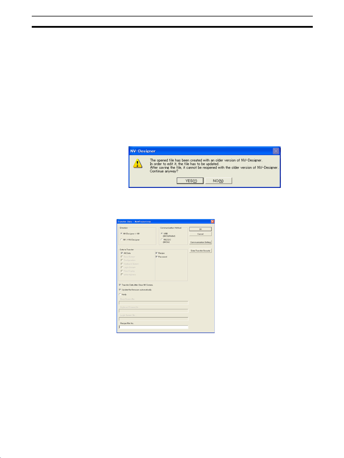
(2) When screen data that was created on an old version of the NV-Designer
is read with the new version of the NV-Designer, the screen data is automatically updated to the new version. (The following confirmation dialog
box will be displayed.)
The following dialog box will be displayed when Transfer is selected from the
PT Menu of the NV-Designer.
Data Transfer Dialog Box
Data to Transfer: All Data
Direction: NV-Designer → NV
Select the Update the firmware
automatically Check Box, and
then click the OK Button.
Updating the firmware and transferring the project will start at the
same time.
Note Automatically updating the
firmware is possible only
when all data is transferred.
Note (1) Never turn OFF the power supply to the PT while the version is being up-
graded. Also, do not unplug the cable between the computer and the NVseries PT. The PT may not restart if transferring the system fails.
(2) The SPMA function cannot be used while the version is being upgraded
or screens are being transferred.
5
Page 27
System Versions Section 1-2
Version Upgrade
Procedure Using NV
Ver_UP Tool
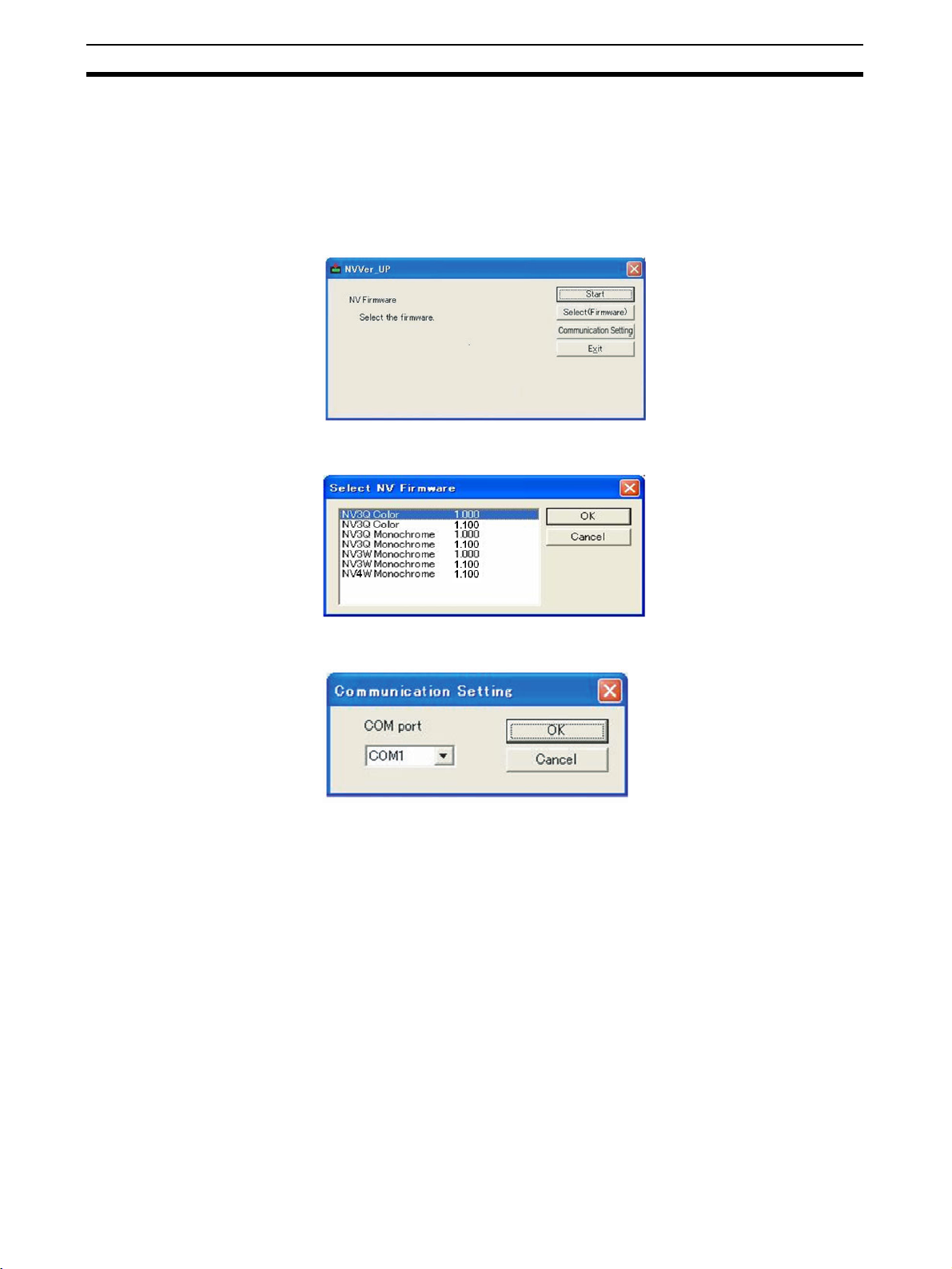
NV Ver_UP is a special tool to upgrade the firmware version of the PT.
The NV Ver_UP version upgrade tool is installed at the same time as the NVDesigner.
Click the Start Button at the bottom left of the window or select All Programs
from the menu displayed by pressing the Ctrl Key and the Esc Key, and then
select CX-One - NV-Designer - Tools - NV Ver_UP from the OMRON Menu.
NV Ver_UP Dialog Box
Select the firmware (Select
(Firmware) Button) and set
the communications conditions (Communication Setting
Button). The applicable settings dialog box will be displayed when either of the
buttons is clicked.
Select NV Firmware Dialog Box
Select the most recent firmware version (i.e., highest version number) for the model
that you are using. Click the
OK Button to return to the NV
Ver_UP Dialog Box.
Communication Setting Dialog Box
Make the communications
setting, and then click the OK
Button to return to the NV
Ver_UP Dialog Box. These
selections cannot be made for
the NV4W and NV3Q.
For the NV3W, select the
COM port that you are actually using.
Upgrading the version will start when the Start Button is clicked.
The NV Ver_UP version upgrade tool will end when the Exit Button is clicked.
Note (1) Never turn OFF the power supply to the PT while the version is being up-
graded.
(2) Do not unplug the cable between the computer and the NV-series PT.
Otherwise, the PT may not restart.
6
Page 28

SECTION 2
PT Internal Data Structure and Display Methods
This section describes the internal data structure of an NV-series PT, how to control the screens displayed on the PT, and
how to control the backlight.
2-1 Internal Data Types and Structure. . . . . . . . . . . . . . . . . . . . . . . . . . . . . . . . . . 8
2-1-1 Overview of Internal Operation . . . . . . . . . . . . . . . . . . . . . . . . . . . . 8
2-1-2 Details of Internal Operation . . . . . . . . . . . . . . . . . . . . . . . . . . . . . . 9
2-2 Displaying Screens . . . . . . . . . . . . . . . . . . . . . . . . . . . . . . . . . . . . . . . . . . . . . 11
2-2-1 Startup Screen. . . . . . . . . . . . . . . . . . . . . . . . . . . . . . . . . . . . . . . . . . 11
2-2-2 Switching Screens. . . . . . . . . . . . . . . . . . . . . . . . . . . . . . . . . . . . . . . 11
2-3 Backlight Display Methods. . . . . . . . . . . . . . . . . . . . . . . . . . . . . . . . . . . . . . . 14
2-3-1 Specifying Backlight Colors. . . . . . . . . . . . . . . . . . . . . . . . . . . . . . . 14
2-3-2 Automatic Backlight OFF Function . . . . . . . . . . . . . . . . . . . . . . . . . 14
7
Page 29
Internal Data Types and Structure Section 2-1
2-1 Internal Data Types and Structure
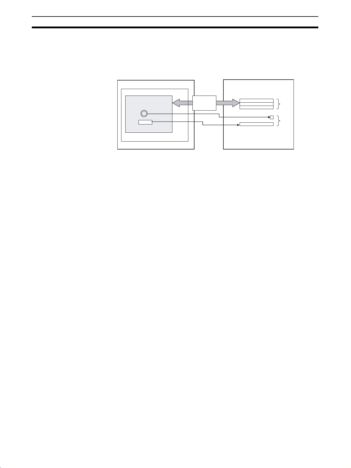
2-1-1 Overview of Internal Operation
This section describes the structure of internal data of an NV-series PT.
NV-series PT
FROM (built-in Flash Memory)
2. Screen is displayed.
Part s
1. System
information is
exchanged.
Screen number,
backlight color,
etc.
The internal data can be largely divided into two parts.
1. System information is exchanged.
System information is constantly exchanged between the PT and PLC, including the screen number and backlight color from the PLC, or to notify
the PLC of PT status.
The system information area is stored in an area called the system memory. System memory must be initialized using the NV-Designer before use.
PLC
System memory
Fixed
area
2. Screen is displayed.
The NV-series PT has multiple screens that contain functional parts selected from the parts libraries. One of the screens can be displayed.
The functional parts specify the desired PLC address and they read/write
data.
8
Page 30
Internal Data Types and Structure Section 2-1
a
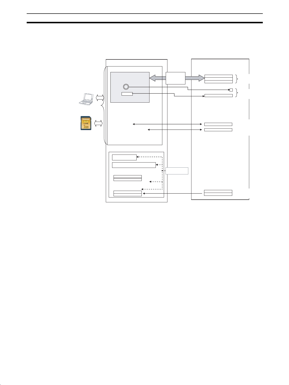
2-1-2 Details of Internal Operation
The NV-series PT has FROM (internal Flash Memory) and SRAM (built-in
RAM). Data is exchanged with the PLC as shown in the following diagram.
NV-series PT PLC
Project Data
FROM (built-in Flash Memory)
• Base screen data
Par ts
888
System
Information
Screen number, backlight
color, etc.
System memory
Fixed area
Allocatable are
NV-Designer
SD memory card
• Keyboard screen data
• Login screen data
• NV configuration data
• Recipe data
*1
• Write Address data
• Flow display data
• Passwords
SRAM (internal RAM)
*1
Clock data
Alarm history data
PT internal memory
Internal memory can be held.
PLC memory hold area
*1: Not supported by the NV3W.
*1
Allocatable area
*1
*1
*1
Battery
Held when power
*1
*1
supply is OFF
Allocatable area
Allocatable area
9
Page 31

Internal Data Types and Structure Section 2-1
■ FROM (built-in Flash Memory)
Stores project data created with the NV-Designer (function data, such as base
screens and NV Configuration).
Project data can be backed up or restored using SD memory cards.
Data Description
Screen
data
Base screen
data
Keyboard screen
data
Login screen
data
NV configuration data
Recipe data Settings to read/write multiple values at one time from or
Write Address
data
Flow display
data
Passwords Settings to restrict displays and operations depending on
Screen data containing parts that have been selected
from the parts libraries.
Screen data containing keyboard parts that open when
the corresponding data parts are pressed.
The Screen data is used to enter passwords according to
the password levels specified for operation security. (Not
supported by the NV3W)
Configuration data related to the NV-series PT that
includes the setting information for functions, such as the
system memory, startup screen number, language
switching, and other functions.
to PLC memory.
Condition and operation settings for writing data to the
PLC according to the status of a memory location in the
PLC while the specified screen is displayed.
Settings for character flows displayed on the bottom of
the screen and the display conditions.
the part and user.
(Not supported by the NV3W)
■ SRAM (Internal RAM)
Stores alarm history data collected by the PT, internal memory values, and
clock data.
Data saved in the built-in RAM will be deleted 1 minute after power supply is
turned OFF, but it can be backed up with an optional Battery. (These functions
are not supported by the NV3W.)
Data Description
Clock data Clock data in PT.
Alarm history data PLC data defined as alarms is constantly monitored and the
PT internal memory NV-series PT internal memory.
PLC memory hold
area
time when the alarm occurred and was removed is recorded
as history data.
The specified area can be held while the power supply is OFF.
PLC data that is constantly read from the specified memory
locations and can be held even when the power supply is
turned OFF.
10
Page 32

Displaying Screens Section 2-2
2-2 Displaying Screens
2-2-1 Startup Screen
Screen 0 is displayed as default when the PT is started.
This screen can be changed in NV Configuration from the NV-Designer.
2-2-2 Switching Screens
One of the following three methods can be used to change the displayed
screen registered in the NV-series PT.
• Switching screens using function switches (functional parts) on PT
screens
• Switching screens using the ladder program
• Switching screens after a specified time (automatic paging)
Switching Screens Using
Function Switches
(Functional Parts) on PT
Screens
The PT screen can be switched using a function switch from a parts library.
The operation depends on the operating mode set for the function switch.
■ Operating Mode: Change Screen
When the function switch is touched, the screen will change to the preset
screen number.
However, the information in the PLC internal system memory (first word in the
Word Area (screen number specified by PLC)) will not be updated.
You can also return to the previous screen by using a function switch with the
operating mode set to.
Example:
NV
Changes to
screen 2.
Switch turned ON.
Operating mode = Change screen
Screen 2
Screen 2
Return to
previous screen
Screen 2
Switch turned ON.
Operating mode = Return to previous screen
11
Page 33

Displaying Screens Section 2-2
■ Operating Mode: Set Value
When the switch is touched, the PT writes the screen number to switch to in
the PLC internal system memory (first word in the Word Area (screen number
specified by PLC)) and the screen is switched.
Example: Data format: 1 word
Output word: D100 (first word in the Word Area of System Memory)
Value: 2 (desired screen number in hexadecimal)
NV
Switch turned ON.
A value is set.
Set D100 to 2. (D100 is the first word in
the Word Area of the Basic
Communications Area.)
PLC
Basic Communications Area
Word Area
D100
2 hex
Screen Number
from PLC
Refer to 7-5 Function Switches for details on Switch Functions.
NV
Screen 2
Changes to screen 2.
PLC
Basic Communications Area
Word Area
D100
2 hex
Screen Number
from PLC
12
Page 34

Displaying Screens Section 2-2
Switching Screens Using
the Ladder Program
Create a ladder program that writes the screen number to the first word of the
PLC system memory to switch the screen.
Communications between the PT and the PLC
PLC
Ladder program
MOV
NV
Continuous communications
Basic Communications Area: Word Addresses
First word
2nd word
3rd word
PLC internal memory
Screen number specified from PLC.
Do not use.
Current Screen Number
Read
Write
Example: Changing from Screen 1 to Screen 2
Screen 1
Screen 2
Specification to
change to screen 2.
Changed to
screen 2.
Example: D100
Example: D100
Basic Communications Area: Word Addresses
2
D101
D102
Basic Communications Area: Word Addresses
D101
D102
Do not use.
1
PLC internal memory
2
Do not use.
2
PLC internal memory
Write
The number of the screen to
display (2) is stored in D102.
Ladder program
MOV
&2
D100
Switching Screens after a
Specified Time (AutoPaging)
Precaution for Correct Operation
Screen numbers are displayed in decimal on the NV-Designer but they must be
in hexadecimal when writing the screen number to the PLC internal system
memory.
The automatic paging function can be used to automatically switch to a specified screen after a specified period of time has passed. Settings are made in
the NV Configuration of the PT.
Application Example:
1. Screen 1 is displayed for 10 seconds and then screen 2 is displayed.
2. Screen 2 is displayed for 5 seconds and then screen 3 is displayed.
NV
Screen 1
Screen 2
After 10 s
Refer to 6-2-6 Auto-Paging Tab Page for details.
After 5 s
Screen 3
13
Page 35

Backlight Display Methods Section 2-3
2-3 Backlight Display Methods
2-3-1 Specifying Backlight Colors
The backlight color of a monochrome NV3W, NV4W or NV3Q can be specified.
It can be specified using one of the following two methods.
1. Initial Settings Backlight colors and operation are set in the base screen properties from the
NV-Designer.
Model Backlight color Operation
NV3W, NV4W White (green), pink (orange), or red Lit or flashing
NV3Q monochrome White, pink, or red Lit or flashing
NV3Q color Not supported. Not supported.
The specified backlight color will be displayed in a rectangle on the left edge
of the title bar.
Indicates that the base screen is white or green.
The backlight colors depend on the model of the PT.
2. Changing the Backlight during Operation
The backlight color can be changed by using specifications from the PLC.
Application Example That Switches the Backlight Color
Color That Indicates an Alarm
Color That Indicates
Normal Operation
"Green"
Color That Indicates an Alarm
Specify the color and either lit or flashing in the Bit Area in system memory.
Refer to 8-1 Switching Backlight Colors for details.
2-3-2 Automatic Backlight OFF Function
The PT can be set so that the backlight automatically turns OFF if the touch
screen not touched for a specified period of time. This can be done on the
Setup 1 Tab Page of the NV Configuration. The time can be set between 1
and 30 minutes.
"Orange"
"Red"
14
Page 36

SECTION 3
NV-Designer Outline and Configuration
This section gives the system requirements for running the NV-Designer, describes the windows and menus of the NVDesigner, and explains the parameters in the NV-Designer Configuration.
3-1 System Requirements . . . . . . . . . . . . . . . . . . . . . . . . . . . . . . . . . . . . . . . . . . . 16
3-1-1 System Requirements . . . . . . . . . . . . . . . . . . . . . . . . . . . . . . . . . . . . 16
3-1-2 Installation . . . . . . . . . . . . . . . . . . . . . . . . . . . . . . . . . . . . . . . . . . . . 16
3-1-3 Re-installation. . . . . . . . . . . . . . . . . . . . . . . . . . . . . . . . . . . . . . . . . . 16
3-1-4 Precautions for Windows Vista and Windows 7. . . . . . . . . . . . . . . . 16
3-2 NV-Designer Window Names and Menus . . . . . . . . . . . . . . . . . . . . . . . . . . . 17
3-2-1 Names of Window Components. . . . . . . . . . . . . . . . . . . . . . . . . . . . 17
3-2-2 Menus . . . . . . . . . . . . . . . . . . . . . . . . . . . . . . . . . . . . . . . . . . . . . . . . 18
3-2-3 Toolbar Functions. . . . . . . . . . . . . . . . . . . . . . . . . . . . . . . . . . . . . . . 23
3-2-4 Graphic Bar Functions . . . . . . . . . . . . . . . . . . . . . . . . . . . . . . . . . . . 24
3-2-5 Screen Manager . . . . . . . . . . . . . . . . . . . . . . . . . . . . . . . . . . . . . . . . 26
3-2-6 Base Screens . . . . . . . . . . . . . . . . . . . . . . . . . . . . . . . . . . . . . . . . . . . 27
3-2-7 Parts Libraries. . . . . . . . . . . . . . . . . . . . . . . . . . . . . . . . . . . . . . . . . . 28
3-3 NV-Designer Configuration . . . . . . . . . . . . . . . . . . . . . . . . . . . . . . . . . . . . . . 29
3-3-1 Customizing the Screen Creation Display . . . . . . . . . . . . . . . . . . . . 29
3-3-2 NV-Designer Configuration . . . . . . . . . . . . . . . . . . . . . . . . . . . . . . . 31
3-3-3 Drive Tab Page . . . . . . . . . . . . . . . . . . . . . . . . . . . . . . . . . . . . . . . . . 32
3-3-4 File Tab Page . . . . . . . . . . . . . . . . . . . . . . . . . . . . . . . . . . . . . . . . . . 33
3-3-5 Grid Tab Page . . . . . . . . . . . . . . . . . . . . . . . . . . . . . . . . . . . . . . . . . . 34
3-3-6 Screen Tab Page . . . . . . . . . . . . . . . . . . . . . . . . . . . . . . . . . . . . . . . . 35
3-3-7 Graphic Tab Page . . . . . . . . . . . . . . . . . . . . . . . . . . . . . . . . . . . . . . . 36
3-3-8 Language Tab Page. . . . . . . . . . . . . . . . . . . . . . . . . . . . . . . . . . . . . . 37
15
Page 37

System Requirements Section 3-1
3-1 System Requirements
3-1-1 System Requirements
Refer to the CX-One Version 4.@ Setup Manual (Cat. No. W463) for the system requirements to operate the NV-Designer.
3-1-2 Installation
Install the NV-Designer using the CX-One or CX-One Lite Installer.
For details, refer to the CX-One Version 4.
provided with the CX-One.
3-1-3 Re-installation
Uninstall the NV-Designer and then re-install it.
For details on how to uninstall the NV-Designer, refer to the CX-One Version
@
Setup Manual (Cat. No. W463) provided with the CX-One.
4.
3-1-4 Precautions for Windows Vista and Windows 7
Because of the operating specifications of Windows Vista and Windows 7, the
file may be saved in a different location to that of a previous version of Windows. Be careful of the following points if you are using Windows Vista and
Windows 7.
@
Setup Manual (Cat. No. W463)
Having Multiple Users of
NV-Designer
File Save Location If you try to save a file in the Program File Folder or other system folders, it will
Files Saved in the
Program File Folder or
Other System Folders
Files saved in the Program Files Folder or other system folders cannot be
shared. To share the Parts Libraries, use a file that can be shared, or copy the
file to each user.
be saved in another location. We recommend that you save files in another
folder, such as the My Documents Folder.
Note The screen data cannot be saved in the Program File Folder or oth-
er system folders.
The file will not be displayed in Explorer even if you open the folder where it is
saved.
Open the folder where the file is saved and click the Compatible Files Button
displayed at the top of the screen to display the file screen.
Additional Information
Additional Information Operating Specifications of Windows Vista and Windows
7
When using Windows Vista or Window 7, files cannot be saved in the Program File Folder or other system folders even if it is specified as the save location in application software, such as NV-Designer. They will be saved it in a
virtual folder (VirtualStore). VirtualStore is a unique folder for each user. It
cannot be shared with other users.
16
Page 38

NV-Designer Window Names and Menus Section 3-2
3-2 NV-Designer Window Names and Menus
3-2-1 Names of Window Components
Graphic bar
Toolbar
Menu bar
Screen Manager
Base Screen
Parts Library
Menu Bar All NV-Designer functions are displayed in the menus.
Toolbar Frequently used commands are displayed as icons on the menu bar.
Graphic Bar Frequently used drawing commands are displayed as icons on the menu bar.
Screen Manager The screens are managed by base screen numbers.
Base Screen Creates a screen. The screen is displayed at the PT’s screen size. The size
cannot be changed, but the display can be zoomed in or out.
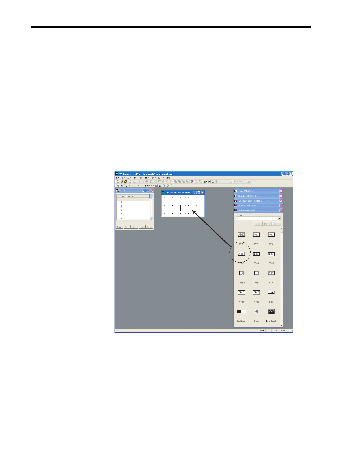
Parts Library Parts used for creating screens are displayed in parts libraries.
Additional Information
When the NV-Designer is started, the Standard Parts Libraries for all parts for
the model that is set will be displayed in front.
17
Page 39

NV-Designer Window Names and Menus Section 3-2
3-2-2 Menus
The NV-Designer’s operations and functions are displayed on menus according to their application.
Menu Submenu/Command Description
File New Displays the Model Selection Dialog Box.
Open Opens the specified NV-Designer project file (*.nvp).
Close Closes an open NV-Designer project file (*.nvp).
Save Saves the specified NV-Designer project file (*.nvp).
Save As Saves the specified NV-Designer project file (*.nvp) with a
Delete Deletes the specified NV-Designer project file (*.nvp).
Print Displays the Print Dialog Box. Specifies the data to be
Print Style Setup Prints the selected items.
Printer Setup Sets up the printer before printing.
Keyboard Screen Displays the Edit Keyboard Screen Dialog Box. Used to
Login Screen Displays the Edit Login Screen Dialog Box. The Login
Export Text The character strings for switching the display language can
Import Text Imports text from a text file. The imported text can be
Exit Exits the NV-Designer.
different name.
printed.
name or delete keyboard screens.
Screens are used to enter passwords according to the password levels specified for the operation security function.
be exported to a text file. The text data can also be edited
and imported.
checked by selecting PT - Multi Language Exchange String
List.
18
Page 40

NV-Designer Window Names and Menus Section 3-2
Menu Submenu/Command Description
Edit Undo Undoes the previous operation.
Redo Redoes the previous operation.
Cut Cuts the selected parts.
Copy Copies the selected parts.
Repeat Creates a base part which is copied to enable the creation of
Paste Pastes the parts that were last cut or copied.
Copy Bitmap of Base
Screen
Align Left Aligns the left sides of the selected graphics.
Right Aligns the right sides of the selected graphics.
Top Aligns the top edges of the selected graphics.
Bottom Aligns the bottom edges of the selected graphics.
Horizontal Center Aligns the horizontal centers of the selected graphics.
Vertical Center Aligns the vertical centers of the selected graphics.
Centering Centers multiple graphics figures.
Rotate Rotates the selected graphics.
Flip Right/Left Flips the selected graphics left to right.
Top/Bottom Flips the selected graphics top to bottom.
Delete Deletes the selected items.
Erase Screen Deletes the base screen
Bring Previous Moves the selected graphic up one layer.
Bring Next Moves the selected graphic back one layer.
Bring Forefront Places the selected graphics on the top.
Bring Behind All Places the selected graphics on the back.
Group Creates a group of character strings, graphics, or parts.
Ungroup Ungroups a group of parts.
Select Selects character strings, graphics, and parts.
Select All Selects all character strings, graphics, and parts on the base
multiple parts with different functions.
Copies the base screen contents as bitmap data.
screen.
19
Page 41

NV-Designer Window Names and Menus Section 3-2
Menu Submenu/Command Description
View Redraw Redraws the contents of the screen that is being edited.
Grid Sets the grid on base screens edited with the NV-Designer.
Toolbar Displays and hides the toolbar.
Status bar Displays or hides the status bar.
Graphic bar Displays and hides the graphic bar.
Zoom 400% Changes the magnification of the base screen that is being
200%
100%
75%
50%
Zoom Box Displays a Zoom Box so that detailed sections can be drawn
Parts No. Displays the parts numbers of all parts on the base screen
Parts Attribute Displays the attributes of all parts on the base screen that is
Status OFF Places a bit switch, function switch, or lamp on the screen in
ON Places a bit switch, function switch, or lamp on the screen in
Language No. Changes the language number when switching the display
Address Cross Reference
edited.
and fine adjustments can be made to positions when creating a base screen.
that is being edited.
being edited.
OFF status.
ON status.
language is being used.
The system memory used for communications with the PLC
and the communications addresses used by parts on the
screen are displayed in a list.
20
Page 42

NV-Designer Window Names and Menus Section 3-2
Menu Submenu/Command Description
PT Transfer Transfer Transfers the base screen data, NV Configuration data, and
Verify Compares the file that is open on the NV-Designer and the
Create SD Memory
Card File
Read from SD Memory Card File
NV Configuration Displays the NV Configuration Dialog Box.
Recipes Specifies the first control address and creates the settings
Flow displays Text messages can be displayed like an electric scoreboard
Writing memory
(Write Address)
Password Displays the Edit Operation Security Password Dialog Box
Multi Language
Exchange String List
Screen Properties Used to set the properties of a base screen (i.e., the name,
Parts Open Parts Library Opens the Parts Library Selection Dialog Box. Select the
Edit Attributes Edits the selected parts.
Draw Used to edit screens of custom switch parts.
Parts List Displays the parts attributes used by a base screen in a list.
other data created on the NV-Designer to the PT.
file transferred to an NV-series PT. If the contents differ, the
differences will be displayed. Compares files read to the NVDesigner.
Names a file in the SD memory card and saves the base
screen data in it.
Reads base screen data from a file on the SD memory card.
Sets basic items, such as the PT’s system memory, parameters for communications with PLCs and computers (NVDesigner), PLC multiple connection, auto-paging, startup
screen settings, Setup 1 settings (clock, backlight, key press
sound, battery error display, file compression, system menu
language, switching display language, backlight brightness,
contrast adjustment), Setup 2 settings (SD memory card
menu), memory hold, recipes, alarm history, line graphs, and
operation security.
for each model for the function that reads and writes the settings for a model from and to the specified PLC address as
commanded by the PLC.
moving across the Flow Display Dialog Box from right to left.
Used to set operations to set or reset bits, set values, perform calculations, etc. in PLC memory when conditions in
the PLC are met while the specified screen is displayed.
so that you can set the passwords when the operation security password function is being used.
If the Switch Display Language Option is selected in the NVDesigner Configuration, the language number and language
type can be selected. The character string for each language number can also be edited in the list.
background, and backlight operation).
parts library to use and click the Open Button.
21
Page 43

NV-Designer Window Names and Menus Section 3-2
Menu Submenu/Command Description
Draw Select Used to select a character string, graphic, functional part,
Text Creates a character string.
Line Creates a straight line.
Continuous line Creates continuous lines.
Rectangle Creates a rectangle.
Pie/Oval Creates a circle or oval.
Arc Creates a circular or oval arc.
Spline Creates a curved line.
Sector Creates a circular or oval sector.
Rounded Rectangle Creates a square with rounded corners.
Polygon Creates a polygon.
Fill In Fills areas enclosed by lines and graphics with a color.
Character Type Sets the language, font, character size, attributes (e.g.,
Color Setup Sets the colors and patterns for graphics.
Line Type Sets the line thickness and type.
Toolbar Resource Report Displays the resource report (amount of free memory and
Base Screen Memory
Usage
NV-Designer Configuration
Convert PLC Model Convert Changes the model of the selected PLC in the file that is
NV Model Convert Changes the model of PT in the file that is being edited.
Close All Closes all open base screens.
Window Cascade Overlaps more than one base screen and displays them.
Arrange Displays more than one base screen side-by-side.
Arrange Icons Returns the toolbar icons to the defaults.
Help Contents Displays the contents of NV-Designer help.
Keyword Displays the window for keyword-based searches of NV-
About NV-Designer Displays the version of the NV-Designer.
etc.
bold), and colors (character and background colors).
memory used by NV configuration, base screens, and keyboard screens).
Displays the amount of memory used by the base screens.
Displays the amount of memory and the communications
addresses used by the parts.
Displays the NV-Designer Configuration Dialog Box.
Sets the configuration of the NV-Designer screen display,
the folder where the parts libraries used by the NV-Designer
are stored, the current folder, whether to enable automatic
backup, the backup time interval, items for creating graphics,
menu and dialog languages, and whether to enable switching the display language.
being edited.
Designer help.
Pop-up Menus on Base Screens
Pop-up Menus Description
Paste Pastes the parts.
Screen Attribute Sets the background colors and patterns.
22
Page 44

NV-Designer Window Names and Menus Section 3-2
guag
Pop-up Menus When a Functional Part or Character String Is Selected
Pop-up Menus Description
Cut Cuts the selected parts.
Copy Copies the selected parts.
Paste Pastes the parts that were last cut or copied.
Functional Parts: Attribute Sets the attributes of a part.
Character String: Character Type Sets the language, font, character size, attributes (e.g., bold), and colors (character
Status ON Places a bit switch, function switch, or lamp on the screen in OFF status.
OFF Places a bit switch, function switch, or lamp on the screen in ON status.
Align Left Aligns the left sides of the selected graphics.
Right Aligns the right sides of the selected graphics.
Top Aligns the top edges of the selected graphics.
Bottom Aligns the bottom edges of the selected graphics.
Horizontal Center Aligns the horizontal centers of the selected graphics.
Vertical Center Aligns the vertical centers of the selected graphics.
Delete Deletes the selected items.
Order Bring Forefront Places the selected graphics on the top.
Bring Behind All Places the selected graphics on the bottom.
Bring Previous Moves the selected graphic up one layer.
Bring Next Moves the selected graphic back one layer.
Group Creates a group of character strings, graphics, or parts.
Ungroup Ungroups a group of parts.
and background colors).
3-2-3 Toolbar Functions
Part Names and
Functions
The names of icons and other items on the toolbar are given below.
Undo Button
Redo Button
Undo Button
Undoes the previous operation.
Redo Button
Redoes the operation that was undone using the Undo Button.
Align Button
Aligns character strings, graphics, and parts.
Enable/Disable Snap Button
Redraw Button
Display/Hide the Graphic Bar Button
Ungroup Button
Group Button
Open a Parts Library Button
Align Button
Lan
Order Button
Parts State Button
e Number Button
Order Button
Changes the order of character strings, graphics, and parts if they are overlapped.
23
Page 45

NV-Designer Window Names and Menus Section 3-2
Parts are set at the foreground as a default.
Open a Parts Library Button
Opens a parts library.
Group Button
Creates a group of character strings, graphics, or parts.
Ungroup Button
Ungroups a group of parts.
Display/Hide the Graphic Bar Button
Displays and hides the graphic bar.
Redraw Button
Redraws the contents of the screen that is being edited.
Enable/Disable Snap Button
Enables/disables the snap function when positioning character strings, graphics, or parts.
Parts State Button
Turns ON/OFF the selected switches and lamps or changes the message part
number.
Language Number Button
Changes the language number of the selected base screen.
Precaution for Correct Operation
The Undo Button is effective only for operations such as drawing and editing
character strings, graphics, and parts, and some operations in editors activated
from the menu bar.
The Undo Button cannot be used for other operations.
3-2-4 Graphic Bar Functions
Part Names and
Functions
Arc/Elliptical Arc Button
Circle/Oval Button
Rectangle Button
Continuous Line Button
Continuous Line Button
Character String Button
Select Button
The names of icons and other items on the graphic bar are given below.
Select Button
Used to select a character string, graphic, functional part, etc.
Curve Button
Segment/Oval Segment Button
Rounded Rectangle Button
Polygon Button
Fill Button
Character Type Button
Color Button
Line Type Button
24
Character String Button
Creates a character string.
Continuous Line Button
Creates a straight line.
Page 46

NV-Designer Window Names and Menus Section 3-2
Continuous Line Button
Creates continuous lines.
Rectangle Button
Creates a rectangle.
Circle/Oval Button
Creates a circle or oval.
Arc/Elliptical Arc Button
Creates a circular or oval arc.
Curve Button
Creates a curved line.
Segment/Oval Segment Button
Creates a circular or oval sector.
Rounded Rectangle Button
Creates a square with rounded corners. The radius of the rounded corners
can be changed in the line settings.
Polygon Button
Creates a polygon.
Fill Button
Fills areas enclosed by lines and graphics with a color.
Character Type Button
Sets the size and style (bold, outline, underline) of characters.
Color Button
Changes the color of character strings and graphics.
Line Type Button
Sets the line thickness and type.
25
Page 47

NV-Designer Window Names and Menus Section 3-2
3-2-5 Screen Manager
The Screen Manager is a dialog box for managing the base screens in a
project.
It can be used as a list for opening screens.
Screens can be copied, pasted, cut, and deleted using the Screen Manager.
Multiple projects can be started simultaneously and editing can be performed
between the Screen Managers.
Project Name and Base
Screen List
The project name is displayed at the upper left of the window.
Serial numbers starting from 0 will be assigned to projects that have not yet
been saved.
This is how projects can be distinguished if multiple projects are created.
Project name
List of screens
0 to 1,023
Command Buttons
A base screen is displayed by its number and name.
Note The number of screens that can be registered depends on the con-
tents of the screens.
Creating Screens Double-click the number of the base screen that you want to create, or select
the number and click the Open Button.
Editing the Screen Copy: Select the screen to copy, click the Copy Button, input a different
screen number, and click the Paste Button.
Move: Select the screen to move, click the Cut Button, input a different
screen number, and click the Paste Button.
Delete: Select the screen to delete and then click the Delete Button.
Additional Information
• The copy, paste, cut, and delete functions can also be accessed by right-clicking on the desired screen.
• The “+” sign will be displayed in the F column if a screen is copied and pasted.
• Multiple Screen Managers can be displayed simultaneously and screens can
be copied or moved between files. However, if the models of NV-series PT are
different and the screen cannot be pasted, a message saying so will be displayed.
26
Page 48

NV-Designer Window Names and Menus Section 3-2
3-2-6 Base Screens
Base screens are essentially the same size as the screens displayed on the
PT.
(You can zoom the screen display in and out.)
Character strings and parts are positioned on the screen to create a base
screen.
Opening a Base Screen
Double-click a number in the number column in the Screen Manager (or
select the number and click the Open Button) to open a base screen.
Double-click a number,
or select the number and
click the Open Button.
Parts of Base Screens
The screen number will be displayed on the top left of the base screen, and
the project name will be displayed on the right of “Base Screen.”
The backlight color is displayed on the top left of the base screen.
Screen number
Base Screen
Backlight color
Project name
Closing a Base Screen
Click the Close Button in the title bar to close the base screen.
If anything has been created on the base screen, the base screen will be registered in the Screen Manager when the base screen is closed.
If nothing has been created on the base screen, the base screen will simply
close.
To close multiple screens at once, select Window – Close All from the Menu
Bar.
Precaution for Correct Operation
1. The base screen will not be saved even it is registered in the Screen Manager.
To save the base screen, select Save from the File Menu and save the entire
project.
2. If the base screen is changed and it is closed, there will be no warning mes-
sage asking whether you want to save it before closing.
27
Page 49

NV-Designer Window Names and Menus Section 3-2
3-2-7 Parts Libraries
A parts library contains parts, such as switches, lamps, data displays, and
keyboards, that you can use to create screens.
They can be easily positioned on base screens by dragging and dropping
them.
When the NV-Designer is started, the Standard Parts Libraries for all parts for
the model that is set will be displayed in front.
Standard Parts Library
Parts Group Selection Button
Parts
Refer to 7-2-2 Parts Libraries for details on the parts libraries.
28
Page 50

NV-Designer Configuration Section 3-3
d
3-3 NV-Designer Configuration
The display while creating base screens and the data save location can be
changed in the NV-Designer Configuration.
3-3-1 Customizing the Screen Creation Display
Grid Display and Setup
1,2,3... 1. Click the Grid Tab from the View Menu.
2. Select the On Option under Display.
3. Select the pitch, snap, and color as required and click the OK Button.
The grid will be displayed on the base screen as shown in the following figure.
Gri
29
Page 51

NV-Designer Configuration Section 3-3
Changing Base Screen Properties (Background and Backlight)
1,2,3... 1. Right-click on the base screen and select Screen Properties from the pop-
up menu.
Or select Screen Properties from the PT Menu.
The following Screen Properties Dialog Box will be displayed.
Example for the NV3W
• The background pattern and color can be changed for the NV3W-
M@@@(@), NV4W-M@@@, and NV3Q-MR@@.
• The background color can be changed for the NV3Q-SW@@.
30
Page 52

NV-Designer Configuration Section 3-3
3-3-2 NV-Designer Configuration
Setting Method Select NV-Designer Configuration from the Tool Menu.
NV-Designer Configuration and Initial Values
Tab Description Item Initial Value
Drive Specify the data folder of the parts
libraries that are used by the NVDesigner.
File Enables/disables automatic
backup and sets the backup interval.
Grid Displays/hides the grid, enables/
disables snapping to the grid, and
sets the grid interval, color, etc.
Screen NV-Designer Screen Display Set-
tings
Graphic Sets the drawing method for cir-
cles and ovals.
Language Sets the language to use by
default.
Parts Library Installation folder/STP
Current Folder C:\documents and set-
tings\ UserName\
Auto-Backup: Every 5 to 30 minutes Not selected.
Display: On/Off Off
Pitch Default/Setup Standard
Setup X direction NV3W: 8 dots
NV4W: 8 dots
NV3Q: 20 dots
Y direction NV3W: 8 dots
NV4W: 8 dots
NV3Q: 20 dots
Snap: Enable/Disable Disabled
Color: Grid Black
Toolbar: Display/Hide View
Graphic Bar: Display/Hide View
Zoom Box: Display/Hide Hide
Parts Information
Fill Pointer Display/Hide View
Tips Display Shows Tips before Sav-
Circle/Oval: Start from Center Point/Start
from Top Left Corner
Default Character Set: Japanese
Menu and Dialog Language: Japanese,
English or Korean
Multi-Language Exchange: On/Off Off
Parts No. Hide
Parts Attribute Hide
Fill Pointer Color Black
View
ing a Project.
Start from Top Left Corner
English
31
Page 53

NV-Designer Configuration Section 3-3
3-3-3 Drive Tab Page
This tab page is used to specify the data folder of the parts libraries that are
used by the NV-Designer.
Setting Description
Parts Library The parts libraries where the data folder is stored is displayed.
To change the folder of the parts libraries, click the Browse
Button and specify the folder for the parts libraries in the dialog
box that is displayed.
32
Page 54

NV-Designer Configuration Section 3-3
3-3-4 File Tab Page
This tab page is used to enable/disable automatic backup and sets the
backup interval.
Setting Description
Current Folder The default folder for saving and reading files is set on the File
Auto-Backup Data is periodically backed up to the disk when the Auto-
Tab Page.
Backup Check Box is selected.
The backup interval can be set in 1 minute increments
between 5 and 30 minutes.
If the NV-Designer is forced to close, backed up project files
will be automatically recovered when it is restarted.
Click the Button and set the time to automatically backup
in the Set Value Dialog Box that is displayed.
33
Page 55

NV-Designer Configuration Section 3-3
3-3-5 Grid Tab Page
This tab page is used to display/hide the grid, enable/disable snapping to the
grid, and set the grid pitch, color, etc.
Setting Description
View Displays or hides the grid on base screens edited with the NV-
Pitch Sets the grid pitch if grids are displayed. (2 to 80)
Snap Enables/disables the snap function which aligns the position of
Color (grid color) Sets the color of the grid displayed on the base screen. Click
Designer.
Default: The grid display is fixed in the X-direction and Y-
direction with the following pitch.
NV3W/NV4W: 8 dots
NV3Q: 20 dots
Setup: The pitch of the grid display can be adjusted in units
of dots.
parts or the starting/ending points of graphics with the grid.
the Button and select the color from the dialog box
that appears.
34
Additional Information
The grid settings can also be displayed from the Menu Bar.
Select View – Grid from the Menu Bar.
It can also be selected using the Alt + G shortcut keys.
Enable/Disable Snap with Toolbar Button
Click the Snap ON/OFF Button on the toolbar.
Page 56

NV-Designer Configuration Section 3-3
3-3-6 Screen Tab Page
This tab page is used to set the screen display setting for the NV-Designer.
Setting Description
Toolbar Sets whether to display or hide the toolbar on the editing
Graphic Bar Sets whether to display or hide the graphic bar on the
Zoom Box Characters and parts drawn on the screen can be
Parts Information Enables/disables the communications address used by
Fill Point Displays/Hides the fill pointer for filling closed areas.
Fill Point Color
Tips Display Displays/hides the message that indicates that there will
Shows Tips before
Saving a Project
screens when the NV-Designer is started.
The toolbar can also be displayed and hidden from the
View Menu on the menu bar.
editing screens when the NV-Designer is started.
The graphic bar can also be displayed and hidden from
the View Menu on the menu bar.
zoomed for checking.
the part.
Parts No.: Displays the parts numbers of all parts
on the base screen.
Parts Attribute: Displays the communications address of
the main attribute PLC of the parts on
the base screen.
Click the button and select the color from the
dialog box that will be displayed.
be multiple saved files from the NV-Designer.
35
Page 57

NV-Designer Configuration Section 3-3
3-3-7 Graphic Tab Page
Sets the drawing method for circles and ovals.
Setting Description
Circle/Oval Changes the method for drawing circles and oval, either start-
Start from
Center Point
ing from the center or from the top left.
A circle or oval is drawn inscribed in a rectangle that has the
specified start point as the center of the circle or oval and for
which the specified start point to the end point is half of the distance between diagonally opposed corners of the rectangle.
Circle
End point
Oval
End point
Start from Top
Left Corner
Start point
Start point
A circle or oval is drawn inscribed in a rectangle that has the
start and end points as a diagonal line.
Circle
Start point
End point
Oval
Start point
End point
36
Page 58

NV-Designer Configuration Section 3-3
3-3-8 Language Tab Page
This tab page sets the language to use by default.
Setting Description
Default Character
Set
Menu and Dialog
Language
Multi-Language
Exchange
Sets the default language when parts are pasted from a parts
library.
It can be chosen from Japanese, English, Simplified Chinese,
Traditional Chinese, Korean, or Turkish.
For example, even if the menu and dialog boxes are displayed
in Japanese, you can set the characters on the parts to be displayed in English or European English.
Sets the language displayed in the menus and dialog boxes.
It can be chosen from Japanese, English, Korean, Simplified
Chinese, or Traditional Chinese.
Sets whether to enable or disable the display language switching function. If switching the display language is enabled, Multi
Language Exchange String List – Edit Properties can be
selected from the PT Menu.
If switching the display language is enabled, a dialog box to
edit character strings for switching display languages will be
displayed to let you select the language for each language
number.
You can register the language and corresponding character
string for each part in advance and then change all registered
parts at the same time using a function switch or a command
from the PLC.
Additional Information
To change the display, the NV-Designer must be restarted.
The set language will be enabled when the NV-Designer is restarted. Restart the
NV-Designer.
37
Page 59

NV-Designer Configuration Section 3-3
38
Page 60

SECTION 4
Overall Flow of NV-Designer Operation
This section describes the overall procedure for using the NV-Designer to set up an NV-series PT for operation.
4-1 Overall Flow of Operation . . . . . . . . . . . . . . . . . . . . . . . . . . . . . . . . . . . . . . . 40
4-2 Creating a Simple Screen . . . . . . . . . . . . . . . . . . . . . . . . . . . . . . . . . . . . . . . . 41
4-2-1 Starting the NV-Designer . . . . . . . . . . . . . . . . . . . . . . . . . . . . . . . . . 41
4-2-2 Using the New Project Wizard . . . . . . . . . . . . . . . . . . . . . . . . . . . . . 42
4-2-3 NV-Designer Configuration (Optional) . . . . . . . . . . . . . . . . . . . . . . 43
4-2-4 Creating Base Screens . . . . . . . . . . . . . . . . . . . . . . . . . . . . . . . . . . . 43
4-2-5 Saving the Screens and Settings (Project) . . . . . . . . . . . . . . . . . . . . 48
4-2-6 Transferring the Final Project to the PT . . . . . . . . . . . . . . . . . . . . . . 49
4-2-7 Setting the PT System Menu . . . . . . . . . . . . . . . . . . . . . . . . . . . . . . 50
4-2-8 Setting Up PLC Communications . . . . . . . . . . . . . . . . . . . . . . . . . . 51
4-2-9 Connecting the PT and PLC . . . . . . . . . . . . . . . . . . . . . . . . . . . . . . . 52
4-2-10 Starting PLC Communications . . . . . . . . . . . . . . . . . . . . . . . . . . . . . 52
39
Page 61

Overall Flow of Operation Section 4-1
4-1 Overall Flow of Operation
Refer to the following steps when using the NV-Designer for the first time.
Start the NV-Designer. *
1
1
↓
Select the Start Menu. *
2
1
↓
Select the PT model and PLC model. *
3
↓
Set system memory. *
4
1
↓
Set the NV-Configuration as required
5
(language settings, etc). *
2
↓
Opening a Base Screen
6
↓
Place a character string above the screen.
7
↓
Drag and drop parts from a parts library
8
such as the Standard Parts Library.
↓
Save the final project.
9
↓
Transfer the final project to the PT.
10
1
*1 For details, refer to SECTION 5 Creating and Saving Projects (Including
Screen Data).
*2 For details, refer to SECTION 3 NV-Designer Outline and Configuration.
40
Page 62

Creating a Simple Screen Section 4-2
0
4-2 Creating a Simple Screen
This section describes how to create a simple screen and operate it.
Screen to be created:
Screen 0
Text
Function
switch
Change to
screen 1
4-2-1 Starting the NV-Designer
When the NV-Designer is started, select the PT model and the PLC it connects to.
1,2,3... 1. Select Program – OMRON – CX-One – NV-Designer to start the NV-De-
signer.
2. Select Create New Project from the Start Menu and click the OK Button.
Screen 1
Text
Data part
Accessed address: D100
Text
Lamp
Accessed address: W100.0
Function switch
Return to previous screen
41
Page 63

Creating a Simple Screen Section 4-2
4-2-2 Using the New Project Wizard
When Create New Project is selected from the Start Menu, the New Project
Wizard will be displayed. Use the following procedure to set up the project.
1,2,3... 1. Set the PT model as shown below in the status for creating the project and
then click the Next Button.
NV Model: NV3Q
NV Model: Monochrome
2. Set the PLC model as shown below for the communications parameters
and then click the Next Button.
PLC model: OMRON SYSMAC-CS/CJ/CP Series
42
3. Set the system memory and then click the OK Button. Set the system
memory by specifying the area for controlling the PT system in the PLC internal memory. The system memory is used to switch between base
screens, so make sure that you set it. In this example, it is left set to the
default values.
Note The default words for the Bit Area are CIO 0 to CIO 2. If CIO 0 to CIO 2 are
allocated to real I/O, be sure to change the settings (e.g., to words in the Work
Area).
Page 64

Creating a Simple Screen Section 4-2
Example: With a CP-series PLC, CIO 0 to CIO 2 are allocated to built-in
inputs, so the words allocated to the Bit Area must always be changed from
the defaults.
4-2-3 NV-Designer Configuration (Optional)
The NV-Designer Configuration can be used to change the display settings for
the NV-Designer.
1,2,3... 1. Select NV-Designer Configuration from the Tool Menu.
2. Change the parameters in the following window.
(Example: A grid can be displayed on the base screens by specifying it in
here.)
4-2-4 Creating Base Screens
Use the following procedure to create the sample screen.
Opening Screen 0
1,2,3... 1. Double-click “0” in the Screen Manager at the upper left of the window. The
base screen with screen number 0 will open.
43
Page 65

Creating a Simple Screen Section 4-2
Setting Character Strings
1,2,3... 1. Click the Button on the graphic bar and click on the base screen
where you want to type in a character string.
2. Enter a character string on screen 0. Enter “Hello! I’m NV.”
3. Select the character string that you just entered and select Character Attribute from the Graphic Menu. Set the character color and size.
Setting Function Switches
Use the following procedure to create a function switch (labeled "Monitor") on
screen 0 to switch the screen display.
1,2,3... 1. Select the function switch parts library.
2. Drag the part called FSW0 and drop it on the base screen.
44
3. Double-click the function switch that was pasted.
Page 66

Creating a Simple Screen Section 4-2
4. On the Basic Setup Tab Page, leave the operation mode set to Change
Screen and the screen set to 1.
5. On the Label Tab Page, set the text to display on the switch as shown below.
ON Switch Display Settings
Text: Enter "Monitor".
Font: Windows (Courier)
Color: Black
OFF Switch Display Settings
Click the OFF Button to change the setting display. Click the Copy from
ON Button. (The ON settings will be copied.)
45
Page 67

Creating a Simple Screen Section 4-2
6. Change the status between OFF and ON at the top right of the tool bar and
check the displays.
Opening Screen 1
1,2,3... 1. Double-click “1” in the Screen Manager at the upper right of the window.
The base screen with screen number 1 will open.
Setting Character Strings
1,2,3... 1. Click the Button on the graphic bar and enter the following character
string on screen 1.
Speed, Alarm
Setting Data
Use the following procedure to create a data part that will display the contents
of a word address in the PLC on screen 1.
1,2,3... 1. Select Data from the Standard Parts Library.
2. Drag the part called Data and drop it on the base screen.
46
Page 68

Creating a Simple Screen Section 4-2
3. Double-click the part that was pasted and specify “D100” on the Basic Setup Tab Page as the communications address in the PLC.
Setting Lamps
Use the following procedure to create a lamp that will display the status of a
bit in the PLC on screen 1.
1,2,3... 1. Select the lamp parts library.
2. Drag the part called Lamp0 and drop it on the base screen.
3. Double-click the part that was pasted and specify “W100.00” on the Basic
Setup Tab Page as the communications address in the PLC.
Setting Function Switches
Use the following procedure to create a function switch (labeled "Return") to
switch the screen to the previously displayed screen (screen 0).
1,2,3... 1. Select the function switch parts library.
2. Drag the part called FSW0 and drop it on the base screen.
3. Double-click the function switch that was pasted.
47
Page 69

Creating a Simple Screen Section 4-2
4. On the Basic Setup Tab Page, select Others for the operating mode and
select Back to Previous Screen.
5. On the Label Tab Page, set the text to display on the switch as shown below.
ON Switch Display Settings
Character string: Enter "Return".
OFF Switch Display Settings
Character string: Set to Copy when ON
4-2-5 Saving the Screens and Settings (Project)
Save the final project.
1,2,3... 1. Select Save As from the File Menu.
2. Specify the save location and click the Save Button.
Important
The created screens and settings (project) can be printed by selecting Print from
the File Menu.
48
Page 70

Creating a Simple Screen Section 4-2
4-2-6 Transferring the Final Project to the PT
1,2,3... 1. Connect the PT and NV-Designer as shown in the following diagrams.
• Example for the NV3W
Connect the tool port on the back of the NV3W to the computer.
NV-Designer
Screen Design Software
Programming Device
Connecting Cable
(RS-232C cable with a round
DIN pin connector for the NV3W)
NV-TOL-3M
• Example for the NV4W/NV3Q
Connect the USB port on the back of the NV4W/NV3Q to the computer.
NV3W
24-V
power supply
NV-Designer
Screen Design Software
NV4W/NV3Q
Commercially available
USB cable
2. Select Transfer - Transfer from the PT Menu. The Data Transfer Dialog Box
will be displayed.
3. Set the method of communications with the PT.
NV3W: RS232C
NV4W/NV3Q: USB
NV4W: Mini B type
NV3Q: B type
24-V
power supply
49
Page 71

Creating a Simple Screen Section 4-2
4. Specify the data to transfer to the PT. Select All Data.
5. Click the OK Button. The project will be transferred to the PT.
4-2-7 Setting the PT System Menu
Example: Set the clock in the NV3Q.
1,2,3... 1. Press the upper left corner for 2 seconds, upper right corner, and then the
lower right corner in order.
2. Touch the Setting Menu Button.
3. Touch the Clock Button.
4. Set the time.
PT
A
B
C
Press the upper left corner
for 2 seconds, upper right corner,
and then the lower right corner
in order.
System Menu
■ System Menu
System Version 1.0
PLC Driver OMRON SYSMAC-CS/CJ/CP
Version 1.0
Setting Menu
Test Menu
ESC
Touch the Setting Button.
System Menu
Touch the Clock Button
and set the time.
Refer to the NV-Series PT Setup Manual (Cat. No. V103) for details on the
System Menu.
50
Page 72

Creating a Simple Screen Section 4-2
4-2-8 Setting Up PLC Communications
The communications settings must be changed in the PLC so that it can communicate with the PT. In this section, an NV3Q PT and a CP-series PLC are
used as an example.
CX-Programmer
Set and transfer the PLC Setup.
Commercially available
USB cable
1,2,3... 1. Start the CX-Programmer.
2. Make the following settings on the Serial Port 1 Tab Page for the CP1E and
the Serial Port Tab Page for other PLCs in the PLC Setup.
Communications setting: User settings
Baud rate: 9,600 bps
Parameters: 7, 1, E
Host link No.: 0
PLC
3. Transfer the PLC Setup from the CX-Programmer to the PLC.
51
Page 73

Creating a Simple Screen Section 4-2
4-2-9 Connecting the PT and PLC
You can connect the PLC to the NV3Q using a RS-232C cable.
NV3Q
PLC
Host Link connection
PLC Connecting Cable
XW2Z-200T-3 (2 m without 5-V line)
XW2Z-500T-3 (5 m without 5-V line)
4-2-10 Starting PLC Communications
1,2,3... 1. Turn ON the PLC.
2. Screen 0 will be displayed. Touch the Monitor Switch.
3. The screen will change to screen 1 and the following information will be
monitored.
24-V power supply
S8JX
52
The contents of D100 will
be displayed.
The lamp color changes
when CIO 100.00 turns ON.
4. Touch the Back Switch to return to the previous screen (screen 0).
Page 74

SECTION 5
Creating and Saving Projects (Including Screen Data)
This section describes how to create, save, and manipulate projects for NV-series PTs, including operations that can be
performed between projects.
5-1 Starting the NV-Designer and Creating New Projects . . . . . . . . . . . . . . . . . . 54
5-1-1 Starting the NV-Designer and Using the New Project Wizard. . . . . 54
5-2 Checking or Converting the Model . . . . . . . . . . . . . . . . . . . . . . . . . . . . . . . . . 59
5-2-1 NV Model Convert . . . . . . . . . . . . . . . . . . . . . . . . . . . . . . . . . . . . . . 59
5-2-2 PLC Model Convert . . . . . . . . . . . . . . . . . . . . . . . . . . . . . . . . . . . . . 60
5-2-3 Checking the Model . . . . . . . . . . . . . . . . . . . . . . . . . . . . . . . . . . . . . 60
5-3 Creating Base Screens. . . . . . . . . . . . . . . . . . . . . . . . . . . . . . . . . . . . . . . . . . . 61
5-4 Positioning Character Strings, Graphics, and Parts . . . . . . . . . . . . . . . . . . . . 62
5-5 Copying and Moving Parts and Screens . . . . . . . . . . . . . . . . . . . . . . . . . . . . . 63
5-5-1 Copying and Moving Parts between Screens . . . . . . . . . . . . . . . . . . 63
5-5-2 Copying and Moving Screens between Projects. . . . . . . . . . . . . . . . 64
5-6 Saving the Project . . . . . . . . . . . . . . . . . . . . . . . . . . . . . . . . . . . . . . . . . . . . . . 65
5-6-1 Save. . . . . . . . . . . . . . . . . . . . . . . . . . . . . . . . . . . . . . . . . . . . . . . . . . 65
5-6-2 Save As . . . . . . . . . . . . . . . . . . . . . . . . . . . . . . . . . . . . . . . . . . . . . . . 65
5-7 Project and Execution Files. . . . . . . . . . . . . . . . . . . . . . . . . . . . . . . . . . . . . . . 66
5-7-1 Projects . . . . . . . . . . . . . . . . . . . . . . . . . . . . . . . . . . . . . . . . . . . . . . . 66
5-7-2 Execution Files of the PT Model after Transfer . . . . . . . . . . . . . . . . 66
53
Page 75

Starting the NV-Designer and Creating New Projects Section 5-1
5-1 Starting the NV-Designer and Creating New Projects
This section describes how to start the NV-Designer and create projects.
5-1-1 Starting the NV-Designer and Using the New Project Wizard
1,2,3... 1. Select Program – OMRON – NV-Designer – NV-Designer Ver.@ from the
Windows Start Menu to start the NV-Designer. (The menu commands may
be different if a different Program Folder was specified during installation.)
2. When the NV-Designer is started, the NV-Designer Dialog Box will be displayed.
3. Select an option in the NV-Designer Dialog Box and click the OK Button.
1
2
3
Item Description
1 Create New Project Select this option to create a new project.
2 Open Existing Project Select this option to read and edit a project that
3 Recent Projects Select this option to open a project that has
is saved to the disk. A dialog box for opening
the project will be displayed for you to select
the project that you want to edit.
been used recently.
54
Page 76

Starting the NV-Designer and Creating New Projects Section 5-1
4. Select Create New Project from the Start Menu. The following Select Model Dialog Box will be displayed.
The following setting status will be displayed at the top of the Wizard Dialog
Box.
Create Project >> Communication Parameters >> System Memory
5. Set the status for creating the project and then click the Next Button
1
2
3
4
5
Item Description
1 NV Model Select the model of the NV-series PT from the
drop-down list. NV3W (default), NV4W, or
NV3Q
2 NV Type *1 Select the model of NV-series PT from the
3 File Name Enter the name of the file in which to save the
4 Position Use the Reference Button to specify the loca-
5 Keep Current Settings Select this check box to use the above settings
drop-down list.
NV3W: Monochrome (default) or vertical and
monochrome
NV4W: 2 shades of gray (default), 8 shades of
gray, vertical with 2 shades of gray, or
vertical with 8 shades of gray
NV3Q: Monochrome (default) or color
project. The default file name is NewProject.
tion where the project is to be saved. The
default location is c:\documents and settings\user\my documents\.
the next time you create a file.
*1 To change the model setting, select Convert - NV Model Convert from the
Tool Menu of the NV-Designer.
55
Page 77

Starting the NV-Designer and Creating New Projects Section 5-1
6. Set the status for the communications settings and then click the Next Button. (Click the Cancel Button to display the Startup Window without a
project.)
1
2
Item Description
1 PLC Model*1 Select the PLC model to connect from the
drop-down list. The default is the OMRON
SYSMAC CS/CJ/CP* Series.
2 Save Current Settings Select this check box to use the above settings
the next time you create a file.
*1 To change the model setting, select Convert – PLC Model Convert from
the Tool Menu of the NV-Designer.
7. Set the status for system memory and then click the Next Button (Click the
Cancel Button to display the Startup Window without a project.)
1
Item Description
1 System Memory
Area
Word Area Sets the memory area and first address of the area of
Bit Area Sets the memory area and first address of the area of
Sets the words used as system memory for basic communications with the PLC.
Refer to 6-2-3 System Memory for details.
memory used for communications between the PT and
PLC in word units, such as for the screen number.
The default is D0 to D2.
memory used for communications between the PT and
PLC in bit units, such as for the screen saver.
The default is 0 to 2.
56
Note The default words for the Bit Area are CIO 0 to CIO 2. If CIO 0 to CIO 2 are
allocated to real I/O, be sure to change the settings (e.g., to words in the Work
Page 78

Starting the NV-Designer and Creating New Projects Section 5-1
Area).
Example: With a CP-series PLC, CIO 0 to CIO 2 are allocated to built-in
inputs, so the words allocated to the Bit Area must always be changed from
the defaults.
8. When the NV-Designer is started, a project is created at the same time.
The following Main Window will be displayed.
9. Double-click “0” in the Screen Manager. Base screen 0 and the Parts Library will open as shown in the following graphic.
Screen manager
Base screen 0
Parts Library
57
Page 79

Starting the NV-Designer and Creating New Projects Section 5-1
Additional Information
Multiple projects can be created and opened simultaneously using the NVDesigner. It is also possible to copy and move screens between projects, as well
as to copy and move parts on a screen.
58
Page 80

Checking or Converting the Model Section 5-2
5-2 Checking or Converting the Model
5-2-1 NV Model Convert
Select Convert - NV Model Convert from the Tool Menu of the NV-Designer.
NV Model Conversion Table
After conversion
NV3W horizontal monochrome
NV3W vertical monochrome
NV4W vertical with 2 shades of gray
NV4W with 2 shades of gray
NV4W with 8 shades of gray
NV4W vertical with 8 shades of gray
NV3Q monochrome
NV3Q color
Before conversion
NV3W horizontal monochrome --- Not sup-
ported.
NV3W vertical monochrome Not sup-
ported.
NV4W with 2 shades of gray Not sup-
NV4W vertical with 2 shades of
gray
NV4W with 8 shades of gray Not sup-
NV4W vertical with 8 shades of
gray
NV3Q monochrome Not sup-
NV3Q color Not sup-
ported.
Not supported.
ported.
Not supported.
ported.
ported.
--- Not sup-
Not supported.
Not supported.
Not supported.
Not supported.
Not supported.
Not supported.
Note Models can be converted only if the number of dots of the model
after the conversion is the same or larger than the model before
conversion. If the NV4W is changed from 8 shades of gray to 2
shades of gray or the NV3Q is changed from color to monochrome,
the NV-Designer will automatically reduce the number of shades
or colors.
Supported.
ported.
--- Not sup-
Not supported.
Supported.
Not supported.
Not supported.
Not supported.
Not supported.
Supported.
ported.
--- Not sup-
Not supported.
Supported.
Not supported.
Not supported.
Supported.
Not supported.
Supported.
ported.
--- Not sup-
Not supported.
Not supported.
Not supported.
Not supported.
Supported.
Not supported.
Supported.
ported.
--- Not sup-
Not supported.
Not supported.
Supported.
Supported.
Supported.
Not supported.
Not supported.
ported.
--- Sup-
Supported.
Supported.
Supported.
Supported.
Not supported.
Supported.
Not supported.
ported.
---
59
Page 81

Checking or Converting the Model Section 5-2
5-2-2 PLC Model Convert
Select Convert – PLC Model Convert from the Tool Menu of the NV-Designer.
5-2-3 Checking the Model
Check the NV-series PT model and PLC model of the screen being created.
Select NV Configuration from the PT Menu of the NV-Designer. Check the
models on the Basic Setup Tab Page.
NV Configuration Dialog Box
60
Page 82

Creating Base Screens Section 5-3
5-3 Creating Base Screens
Click “0” in the Screen Manager. Base screen 0 and the Parts Library will be
displayed.
Screen Manager
Double-click "0."
Base screen 0
Parts Library
Screen number Project name
Additional Information
Select Zoom from the View Menu to zoom in and out of the base screen.
61
Page 83

Positioning Character Strings, Graphics, and Parts Section 5-4
5-4 Positioning Character Strings, Graphics, and Parts
You can position character strings, graphics, and parts on the opened base
screen. Refer to the following methods for positioning.
Refer to 7-1-2 Entering Character Strings and Graphics for details on how to
position character strings and graphics.
Refer to 7-2-1 Positioning Parts for details.
Note Bit map data that is on the clipboard can be pasted on a screen.
62
Page 84

Copying and Moving Parts and Screens Section 5-5
5-5 Copying and Moving Parts and Screens
5-5-1 Copying and Moving Parts between Screens
With the NV-Designer, you can copy or move parts and graphics on base
screens between different projects or within the same project.
Copying Parts between
Screens
Note If you copy parts between screens for different models of PT, the parts will
Moving Parts between
Screens
Right-click the part to be copied and select Copy. Then right-click where you
want the copy to be made and select Paste.
→
automatically be converted to allow for differences in parts colors and functionality between the PTs.
Right-click the part to be moved and select Cut. Then right-click where you
want to move the part and select Paste.
→
Note If you move parts between screens for different models of PT, the parts will
automatically be converted to allow for differences in parts colors and functionality between the PTs.
63
Page 85

Copying and Moving Parts and Screens Section 5-5
5-5-2 Copying and Moving Screens between Projects
With the NV-Designer, you can copy or move base screens between different
projects.
Copying Screens between
Projects
Moving Screens between
Projects
Right-click the screen to copy in the Screen Manager and select Copy (or
select the screen and click the Copy Button). Then right-click the screen
where you want the copy to be made in the Screen Manager for a different
product and select Paste (or select the screen and click the Paste Button).
After pasting the screen, you can double-click it to display the copy.
→
Right-click the screen to move in the Screen Manager and select Cut (or
select the screen and click the Copy Button). Then right-click the screen
where you want the copy to be made in the Screen Manager for a different
product and select Paste (or select the screen and click the Paste Button).
After moving the screen, you can double-click the screen to display it.
→
Note You cannot copy screens between different models of PT.
64
Page 86

Saving the Project Section 5-6
5-6 Saving the Project
5-6-1 Save
Select Save from the File Menu.
5-6-2 Save As
1,2,3... 1. Select Save As from the File Menu. The following message will be dis-
played.
To stop displaying this message, clear the Display this dialog box when
saving Check Box.
2. Click the Close Button.
3. Specify the save location in the Save As Dialog Box and Click the Save
Button.
65
Page 87

Project and Execution Files Section 5-7
5-7 Project and Execution Files
5-7-1 Projects
Projects include screen data and settings. With the NV-Designer, PT screen
data and the model settings are managed together as a project.
When the created project is saved, the project file (.nvp: the file that is related
to the NV-Designer and started to access the project) that is named at that
time and a project folder will be newly created under the specified folder when
the project is saved. Files with project settings will be created in the Project
Folder.
When "sample" is specified as the file name.
Folder specified for saving
Project structure data
sample.nvp:
Project profile (.nbk)
sample.nbk :
sample.INI :
sample.WDF:
Folder specified for
saving with the same
name as the file
Example: sample
Setting data
GNRL0000-.BSD:
sample.HSY:
sample.R00:
sample.ALK:
sample.SPW:
• Screen data is saved in base screen data files (.BSD). A separate file is
used for each screen.
• Setting files are created when the settings are saved.
5-7-2 Execution Files of the PT Model after Transfer
When projects are transferred to the PT or SD memory card from the NVDesigner, they are converted to the following PT execution files.
• Save folder and execution file name after transfer.
Save folder:
Base screens: base***.gsd ***: 000 to fff is the screen number.
Keyboard screens keyb***.gsd ***: 000 to fff is the keyboard number.
Login screens: login***.gsd ***: 000 to fff is the login screen number.
PLC driver: plc_drv.gsd
NV Configuration: nvconfig***.gsd
Recipes: recip***.gsd ***: 000 to fff is the recipe number.
Write Address: devw.gsd
Flow text: flow.gsd
Passwords: pswd.gsd
Firmware: firmware.gsd
Project backup file (.nvk) (for system)
Initialization file (.INI)
PLC driver file (.WDF)
Base screen data (one file for each screen)
NV-Configuration file (.HSY)
Recipe file (.R00)
Flow text file (.ALK)
Passwords (.SPW)
66
Page 88

This section describes the parameters in the NV Configuration in detail.
6-1 NV Configuration . . . . . . . . . . . . . . . . . . . . . . . . . . . . . . . . . . . . . . . . . . . . . . 68
6-1-1 Setting Parameters . . . . . . . . . . . . . . . . . . . . . . . . . . . . . . . . . . . . . . 68
6-1-2 NV Configuration Parameters . . . . . . . . . . . . . . . . . . . . . . . . . . . . . 69
6-1-3 Default Setting . . . . . . . . . . . . . . . . . . . . . . . . . . . . . . . . . . . . . . . . . 71
6-2 Setting the NV Configuration from the NV-Designer. . . . . . . . . . . . . . . . . . . 72
6-2-1 Setting Method . . . . . . . . . . . . . . . . . . . . . . . . . . . . . . . . . . . . . . . . . 72
6-2-2 Basic Settings Tab Page . . . . . . . . . . . . . . . . . . . . . . . . . . . . . . . . . . 74
6-2-3 System Memory . . . . . . . . . . . . . . . . . . . . . . . . . . . . . . . . . . . . . . . . 75
6-2-4 Communication Parameters Tab Page . . . . . . . . . . . . . . . . . . . . . . . 79
6-2-5 PLC Multiple Connection Tab . . . . . . . . . . . . . . . . . . . . . . . . . . . . . 81
6-2-6 Auto-Paging Tab Page . . . . . . . . . . . . . . . . . . . . . . . . . . . . . . . . . . . 82
6-2-7 Start-up Screen Tab Page . . . . . . . . . . . . . . . . . . . . . . . . . . . . . . . . . 84
6-2-8 Setup 1 Tab Page. . . . . . . . . . . . . . . . . . . . . . . . . . . . . . . . . . . . . . . . 85
6-2-9 Setup 2 Tab Page (NV4W/NV3Q Only). . . . . . . . . . . . . . . . . . . . . . 90
6-2-10 Hold Memory Tab Page (NV4W/NV3Q Only) . . . . . . . . . . . . . . . . 91
6-2-11 Other Settings . . . . . . . . . . . . . . . . . . . . . . . . . . . . . . . . . . . . . . . . . . 92
SECTION 6
NV Configuration
67
Page 89

NV Configuration Section 6-1
6-1 NV Configuration
The initial conditions must be set in NV Configuration before using the PT.
6-1-1 Setting Parameters
There are the following two methods for setting parameters in the NV Configuration.
1,2,3... 1. Setting from the NV-Designer
First, set the NV Configuration parameters in the NV-Designer, and then
connect the NV-Designer to the PT and transfer the NV Configuration to
the PT.
NV-Designer Screen
Design Software
PT
NV Configuration
transferred.
2. Setting from the System Menu on the PT
After transferring the NV Configuration, parts of it can be modified from the
PT System Menu using the following procedure. Touch the front panel on
the upper left corner, upper right corner, and lower right corner in that order
to display the System Menu.
PT
(1)
Touch the upper left corner (1),
upper right corner (2), and then
the lower right cornet (3) in order.
(2)
(3)
System Menu
The following parameters can be set from the PT System Menu only:
PT clock, LCD contrast, backlight, touch switches, and memory initialization.
68
Page 90

NV Configuration Section 6-1
6-1-2 NV Configuration Parameters
Tab
page
Basic
Setup
Communication Parameters Supported. Supported. Supported. Supported. Supported.
PLC Multiple Connection
Auto-Paging Supported. Supported. Supported. Supported. Not supported.
Startup Screen Supported. Supported. Supported. Supported. Not supported.
Setup 1 Clock PLC Clock Supported. Supported. Supported. Supported. Not supported.
Setup 2 SD Memory Card Menu Not supported. Supported. Supported. Supported. NV3W: Not
Hold
Memory
Recipe Supported. Supported. Supported. Supported. Not supported.
Alarm History Not supported. Supported. Supported. Supported. Not supported.
Title Supported. Supported. Supported. Supported. Not supported.
PLC Model Supported. Supported. Supported. Supported. Not supported.
Displaying the NV model Supported. Supported. Supported. Supported. Not supported.
System Memory Area Supported. Supported. Supported. Supported. Not supported.
Automatic Backlight Off Supported. Supported. Supported. Supported. Not supported.
Key Press Sound Supported. Supported. Supported. Supported. Not supported.
Battery Error Display Not supported. Supported. Supported. Supported. Not supported.
File Compression Supported. Supported. Supported. Supported. Not supported.
System Menu Language Supported. Supported. Supported. Supported. NV3W: Not
Setup of Multi-Language
Exchange
Backlight Brightness Setting
Contrast Adjustment Not supported. Not supported. Supported. Supported.
Hold PLC Memory Value Not supported. Supported. Supported. Supported. Not supported.
Holding Internal Memory
Val ue
Item PT Setting Method
NV3W NV4W NV3Q NV-Designer System Menu
on the PT
*1
NV Clock Not supported. Supported. Supported. Supported. NV3W: Not
Summer Time Not supported. Supported. Supported. Supported. Not supported.
Transfer Outside Not supported. Supported. Supported. Supported. Not supported.
Not supported. Supported Supported Supported Not supported.
supported.
NV4W: Sup-
ported.
NV3Q: Sup-
ported.
supported.
NV4W: Sup-
ported.
NV3Q: Sup-
ported.
Supported. Supported. Supported. Supported. Not supported.
Supported.
(Adjust and
transfer)
Not supported. Supported. Supported. Supported. Not supported.
Supported.
(Adjust and
transfer)
Supported.
(Adjust and
transfer)
Supported. Supported.
supported.
NV4W: Sup-
ported.
NV3Q: Sup-
ported.
69
Page 91

NV Configuration Section 6-1
Tab
page
Line Graphs Supported. Supported. Supported. Supported. Not supported.
Operation Security Not supported. Supported. Supported. Supported. NV3W: Not
Item PT Setting Method
NV3W NV4W NV3Q NV-Designer System Menu
on the PT
supported.
NV4W: Sup-
ported.
NV3Q: Sup-
ported.
*1 PLC multiple connection is supported when communications are per-
formed using Modbus.
70
Page 92

NV Configuration Section 6-1
6-1-3 Default Setting
The default settings for the NV Configuration are given below.
Tab page Item Setting
Basic Setup PLC Model OMRON SYSMAC-CS/CJ/CP Series Host Link
System Memory Area: Word Area D0 to D2
System Memory Area: Bit Area 0 to 2
Communication
Parameters
PLC Multiple Connection
Auto-paging Auto-paging Off
Start-up Screen Start-up Screen No. 0
Setup 1 Clock PT clock
Setup 2 SD Memory Card Menu: Automatic Display Off
Hold Memory
Recipe Use Recipe Off
Alarm History
Line Graphs Record Not supported.
Operation Security
COM Port: Baud Rate 9,600 bps
COM Port: Data Length 7
COM Port: Stop Bits 1
COM Port: Parity Bit Even
Communication Error Handling: Retry 5 times
Communication Error Handling: Wait time 3 seconds
Transmission Delay 0 ms
PLC Multiple Connection No
Delay 0
Clock: Summer Time
Clock: Transfer Outside
Automatic Backlight OFF Off
Key Press Sound Enabled
Battery Error Display
File Compression On
System Menu Language English
Setup of Multi-Language Exchange: Refer to
PLC
Backlight Brightness Setting Off
Holding PLC Memory
Hold NV Internal Memory Value: Data memory Off
Hold NV Internal Memory Value: Internal
Relay
*1
Record
Operation Security Function Available
*1
*1
*1
*1
*1
Off
Off
Off
Off
Off
Off
Not supported.
Off
*1 These functions are not supported by the NV3W.
71
Page 93

Setting the NV Configuration from the NV-Designer Section 6-2
6-2 Setting the NV Configuration from the NV-Designer
This section describes the procedure for setting the NV Configuration from the
NV-Designer. Refer to the Setup Manual for information on how to set the NV
Configuration from the System Menu.
6-2-1 Setting Method
1,2,3... 1. Select PT – NV Configuration from the NV-Designer Menu to open the NV
Configuration Dialog Box. If multiple project files are already open, the Select File Dialog Box will be displayed. Select a project file to set up.
2. Set the required items. (Refer to 6-2-2 Basic Settings Tab Page and follow-
ing sections for details.)
3. Save the file and transfer it to the PT. (Refer to 9-1 Transferring Screens
from the NV-Designer for details.)
Note The settings will be reflected in the PT once the setting file has been trans-
ferred from the NV-Designer.
72
Page 94

Setting the NV Configuration from the NV-Designer Section 6-2
NV Configuration Dialog Box
Tab page Description Reference
Basic Setup Sets the PT model and system memory. Set the first
words in the Word Area and Bit Area in the PLC.
Communication
Parameters
PLC Multiple Connection (NV4W/
NV3Q only)
Auto-Paging Enables auto-paging, which automatically switches the
Start-up Screen Sets the number of the screen displayed on the PT when
Setup 1 Sets the clock reference, automatic backlight OFF func-
Setup 2 (NV4W/
NV3Q only)
Hold Memory
(NV4W/NV3Q only)
Recipe Sets whether to use the recipe function, and also the
Alarm History
(NV4W/NV3Q only)
Line Graph Sets sampling for groups 0 to 4 for line graphs. 7-10 Line Graphs
Password
(NV4W/NV3Q only)
Sets the serial communications settings between the PT
and PLC.
Sets parameters when multiple PLCs or OMRON EJ1
Temperature Controllers are connected using Modbus.
screen displayed on the PT after a certain period of time.
the power supply is turned ON and its display time.
tion, key press sound, battery error display, file compression, display language switching, backlight brightness,
and contrast. (NV3W only)
Enables/disables displaying the SD Memory Card Menu. 6-2-9 Setup 2 Tab Page (NV4W/NV3Q
Sets the words to be held for PLC and PT internal memory.
control address for the recipe function.
Sets sampling for groups 0 and 1, as well as the control
address for the alarm history.
Sets security using passwords. 8-6 Security Functions
6-2-2 Basic Settings Tab Page
6-2-4 Communication Parameters Tab
Page
6-2-5 PLC Multiple Connection Tab
6-2-6 Auto-Paging Tab Page
6-2-7 Start-up Screen Tab Page
6-2-8 Setup 1 Tab Page
Only)
6-2-10 Hold Memory Tab Page (NV4W/
NV3Q Only)
8-5 Recipes
7-11 Alarm Lists (NV4W/NV3Q)
Initialize Button The following message will be displayed when the Initialize Button is clicked in
the NV Configuration Dialog Box.
Click the OK Button to reset all parameters to default values.
73
Page 95

Setting the NV Configuration from the NV-Designer Section 6-2
6-2-2 Basic Settings Tab Page
This tab page is used to set the system memory for basic communications
with the PLC. Always set the system memory when you create a new project.
Item Description
Title Input the title of the configuration file (internal file). Titles are
NV Model Sets the model of PT to be displayed when the NV-Designer is
PLC Model Sets the model of PLC to be displayed when the NV-Designer
System Memory Sets system memory. Set the first words in the Word Area and
Initialize Click this button to reset all parameters to their default set-
Setting System Memory System Memory
Sets the areas used in the system memory.
Refer to 6-2-3 System Memory for information on the system memory.
Word Area
Sets the memory area and first address of the area of memory used for communications between the PT and PLC in word units, such as for the screen
number.
convenient when there are several configurations for different
PTs.
started.
Note If you change the PT model, select Convert - NV Model
Convert from the Tool Menu.
is started.
Note If you change the PLC model, select Convert – PLC
Model Convert from the Tool Menu.
Bit Area.
tings.
74
Bit Area
Sets the memory area and first address of the area of memory used for communications between the PT and PLC in bit units, such as for the screen
saver. Click the button by the Word Area or Bit Area in the System Memory
Area to display the Address Setting Dialog Box. Set the PLC memory area
and address in this dialog box.
Page 96

Setting the NV Configuration from the NV-Designer Section 6-2
Word Area Bit Area
Item Description
1 Area Click the Area Box and select an area from the pull
down menu.
2 Channel No. (i.e., word
address)
3 Bit Number (When
setting Bit Area)
Enter the address directly or by using the keypad.
Corrections can be made by clicking the Back or
Clear Button.
Precaution for Correct Operation
Do not allocate words that are used for real I/O to the Bit Area in system memory. The output status for allocated bits may turn ON or OFF, or the operation of
the PT may change when an input turns ON or OFF.
Note (1) Word Area
Sets the memory area and first address of the area of memory used to
read/write data in word units, such as for the screen number.
(2) Bit Area
Sets the memory area and first address of the area of memory used to read/write data in bits, such as for the automatic backlight OFF function. Refer to 6-2-3 System Memory.
6-2-3 System Memory
System Memory The PT is constantly communicates with the internal memory of the PLC. The
PLC internal memory is divided into the following two areas.
■ System Memory
The system memory is used to control the system, such as for specifying the
screen number or backlight status. The specified words in the PLC memory
are allocated for communications, which are performed constantly.
■ Communications Addresses for Parts
The addresses used by parts can be specified freely. Communications are
performed only for the addresses used by the parts displayed on the screen.
75
Page 97

Setting the NV Configuration from the NV-Designer Section 6-2
System Memory
PT
Continuous
communications
Specifies the screen
number and backlight
color.
PLC internal memory
Communications
Addresses for Parts
An address is specified
for each part.
PLC
Operations Using the
System Memory
Contents of System
Memory
The following parameters can be specified and monitored from the system
memory.
• Specify: Displayed screen number, backlight color, backlight ON/flashing.
• Monitor: Displayed screen number, data being input, battery backup
error, low battery.
PLC
PT
Specification
Screen number,
backlight color, etc.
Monitor
Displayed screen
number, input data, etc.
System memory
Word Area
N
N+1
N+2
Bit Area
N
N+1
N+2
Screen Number from PLC
Not used.
Current Screen Number
Not used.
Three words are allocated for the Word Area and three words are allocated for
the Bit Area.
Word Area
N
N+1
N+2
N
N+1
N+2
Three consecutive words
Bit Area
Three consecutive words
76
The following words are set as the system memory by default.
Word Area: D0 to D2
Bit Area: 0 to 2
The first address can be changed in the NV Configuration from the NVDesigner.
Page 98

Setting the NV Configuration from the NV-Designer Section 6-2
NV3W System Memory
Word Area
Map
Bits
1514131211109876543210
Word
N + 0 Screen Number from PLC (PLC tells the NV3W to using this number.)
N + 1 Do not use.
N + 2 Current Screen Number (PLC reads this number from the NV3W.)
Word Area Description
Screen Number from
PLC
Current Screen
Number
This word contains the number in hexadecimal of the screen
specified by the PLC for the NV3W to display.
This word contains the number in hexadecimal of the screen
currently displayed by the NV3W.
Bit Area
Bits
1514131211109876543210
Word
N + 0
Buzzer
Screen Display Bit
Backlight Control Enable Bit
Backlight ON/Flash Bit
Backlight color
Key Press Sound Disable Bit
N + 1 Do not use.
N + 2
Bit Area Description
Buzzer Turn ON this bit to turn ON the buzzer.
Screen Display Bit Turn ON this bit to make the PT display the screen specified by
the PLC. (This bit is effective only when it changes from OFF
to ON.)
Backlight Control
Enable Bit
Backlight ON/Flash
Bit
Backlight color 00: Not lit, 01: Green (white), 10: Red, 11: Orange (pink)
Key Press Sound
Disable Bit
Data Entry Flag This bit will be ON while data is being entered and will turn
Turn ON this bit to enable controlling the backlight (flashing
and color).
OFF: Lit (normal), ON: Flashing
When turned ON, disables the key press sound so that there is
no sound when the PT touch panel is touched even if the key
press sound is enabled in the NV Configuration from the NVDesigner.
OFF when data entry has been completed. (This bit is effective only when a keyboard is being used.)
Data Entry Flag
77
Page 99

Setting the NV Configuration from the NV-Designer Section 6-2
NV4W/NV3Q System
Word Area
Memory Map
Bits
1514131211109876543210
Word
N + 0 Screen Number from PLC (PLC tells the NV4W/NV3Q to using this number.)
N + 1 Do not use.
N + 2 Current Screen Number (PLC reads this number from the NV4W/NV3Q.)
Word Area Description
Screen Number from
PLC
Current Screen
Number
This word contains the screen number specified by the PLC
for the NV4W/NV3Q to display in hexadecimal.
This word contains the number in hexadecimal of the screen
currently displayed on the NV4W/NV3Q.
Bit Area
Bits
1514131211109876543210
Word
N + 0
Buzzer
Screen Display Bit
Backlight Control Enable Bit
Backlight ON/Flash Bit
Backlight color
Key Press Sound Disable Bit
N + 1 Do not use.
N + 2
Bit Area Description
Buzzer Turn ON this bit to turn ON the buzzer.
Screen Display Bit Turn ON this bit to make the PT display the screen speci-
fied by the PLC. (This bit is effective only when it changes
from OFF to ON.)
Backlight Control
Enable Bit
Backlight ON/Flash Bit OFF: Lit (normal), ON: Flashing
Backlight color NV4W:
Turn ON this bit to enable controlling the backlight (flashing
and color).
00: Not lit, 01: Green (white), 10: Red, 11: Orange (pink)
NV3Q Monochrome:
00: Not lit, 01: White, 10: Red, 11: Pink
NV3Q Color:
00: Not lit, 01: Lit, 10: Lit, 11: Lit
Password Change Screen Flag
Login Screen Flag
Battery Low Flag
Battery Backup Error Flag
Data Entry Flag
78
Page 100

Setting the NV Configuration from the NV-Designer Section 6-2
Key Press Sound Disable Bit
Data Entry Flag This bit will be ON while data is being entered and will turn
Login Screen Flag This bit will be ON while the login screen is being displayed
Password Change
Screen Flag
Battery Backup Error
Flag
Battery Low Flag This bit will turn ON when the battery charge becomes low.
When turned ON, disables the key press sound so that
there is no sound when the PT touch panel is touched even
if the key press sound is enabled in the NV Configuration
from the NV-Designer.
OFF when data entry has been completed. (This bit is
effective only when a keyboard is being used.)
and will turn OFF when it has closed.
This bit will be ON while the password change screen or
password management screen is being displayed and will
turn OFF when the screen has closed.
This bit will be ON if clock data or PLC memory holding
data held in the SRAM (built-in RAM) are not backed up
properly. (This bit will also be ON if SRAM is not backed up
by the battery.
window.
Replace the battery within a week after this bit turns ON.
"" is displayed at the lower right of the screen.
(
"" is displayed at the lower right of the
*1
)
*1
)
*1 If displaying battery errors is not enabled, it will not be displayed.
*2 The Battery Backup Error Flag and Battery Low Flag will function even if
the display for a discharged battery is disabled.
6-2-4 Communication Parameters Tab Page
Sets the serial communications settings between the PT and PLC.
Note Communications parameters can be set from the Port Screen in the Setting
Mode of the PT System Menu.
■ NV3W
79
 Loading...