

Page 1

Cat. No. V061-E1-06
NT-Series
Support Tool
for Windows Ver.4.
OPERATION MANUAL
Page 2

Page 3

NT-series
Support Tool for Windows Ver.4.j
Operation Manual
Revised July 2010
Page 4

iv
Page 5

Introduction
The NT-series Support Tool for Windows (Ver. 4.j) is a software package for creating and maintaining
screen data used by OMRON Programmable Terminals. Be sure to read and understand the functions
and performance of the Support Tool before you attempt to use a Programmable Terminal. When using
the Support Tool, be sure to have the manuals for the Programmable Terminal close at hand.
Intended Audience
This manual is intended for the following personnel, who must also have knowledge of electrical systems
(an electrical engineer or the equivalent) and computers.
S Personnel in charge of introducing FA systems into production facilities
S Personnel in charge of designing FA systems
S Personnel in charge of installing and connecting FA equipment
S Personnel in charge of managing FA systems and facilities
Notice
This manual provides information required to use the NT-series Support Tool for Windows (Ver. 4.j). Be
sure to read this manual before attempting to use the Support Tool, and keep the manual close at hand for
reference during operation.
E OMRON, 2000
All rights reserved. No part of this publication may be reproduced, stored in a retrieval system, or transmitted, in any
form, or by any means, mechanical, electronic, photocopying, recording, or otherwise, without the prior written permission of OMRON.
No patent liability is assumed with respect to the use of the information contained herein. Moreover, because
OMRON is constantly striving to improve its high-quality products, the information contained in this manual is subject to change without notice. Every precaution has been taken in the preparation of this manual. Nevertheless,
OMRON assumes no responsibility for errors or omissions. Neither is any liability assumed for damages resulting
from the use of the information contained in this publication.
Trademarks
MicrosoftR, MS-DOSR, WindowsR and Windows NTR are either registered trademarks or Trademarks of Microsoft Corporation in the United States and/or other countries.
PLC names of MELSEC FX, A series and FX-2PIF of MELSEC F series are registered trademarks of Mitsubishi
Electric Corporation.
Hewlett-Packard, HP, PCL and Laser Jet are registered trademarks of Hewlett-Packard Company.
v
Page 6

vi
Page 7
Read and Understand this Manual
Á
Á
Á
Á
Á
Á
Á
Á
Á
Á
Á
Á
Á
Á
Á
Please read and understand this manual before using the product. Please consult your OMRON
representative if you have any questions or comments.
Warranty and Limitations of Liability
WARRANTY
OMRON’s exclusive warranty is that the products are free from defects in materials and workmanship for
БББББББББББББББББББББББББББББББ
a period of one year (or other period if specified) from date of sale by OMRON.
БББББББББББББББББББББББББББББББ
OMRON MAKES NO WARRANTY OR REPRESENTATION, EXPRESS OR IMPLIED, REGARDING
БББББББББББББББББББББББББББББББ
NON–INFRINGEMENT, MERCHANTABILITY, OR FITNESS FOR PARTICULAR PURPOSE OF THE
БББББББББББББББББББББББББББББББ
PRODUCTS. ANY BUYER OR USER ACKNOWLEDGES THAT THE BUYER OR USER ALONE HAS
БББББББББББББББББББББББББББББББ
DETERMINED THAT THE PRODUCTS WILL SUITABLY MEET THE REQUIREMENTS OF THEIR
INTENDED USE. OMRON DISCLAIMS ALL OTHER WARRANTIES, EXPRESS OR IMPLIED.
БББББББББББББББББББББББББББББББ
БББББББББББББББББББББББББББББББ
LIMITATIONS OF LIABILITY
OMRON SHALL NOT BE RESPONSIBLE FOR SPECIAL, INDIRECT, OR CONSEQUENTIAL
DAMAGES, LOSS OF PROFITS OR COMMERCIAL LOSS IN ANY WAY CONNECTED WITH THE
БББББББББББББББББББББББББББББББ
PRODUCTS, WHETHER SUCH CLAIM IS BASED ON CONTRACT, WARRANTY, NEGLIGENCE, OR
БББББББББББББББББББББББББББББББ
STRICT LIABILITY.
БББББББББББББББББББББББББББББББ
In no event shall the responsibility of OMRON for any act exceed the individual price of the product on
БББББББББББББББББББББББББББББББ
which liability is asserted.
БББББББББББББББББББББББББББББББ
IN NO EVENT SHALL OMRON BE RESPONSIBLE FOR WARRANTY, REPAIR, OR OTHER CLAIMS
БББББББББББББББББББББББББББББББ
REGARDING THE PRODUCTS UNLESS OMRON’S ANALYSIS CONFIRMS THAT THE PRODUCTS
БББББББББББББББББББББББББББББББ
WERE PROPERLY HANDLED, STORED, INSTALLED, AND MAINTAINED AND NOT SUBJECT TO
БББББББББББББББББББББББББББББББ
CONTAMINATION, ABUSE, MISUSE, OR INAPPROPRIATE MODIFICATION OR REPAIR.
vii
Page 8
Application Considerations
Á
Á
Á
Á
Á
Á
Á
Á
Á
Á
Á
Á
Á
Á
Á
Á
Á
Á
Á
Á
Á
Á
SUITABILITY FOR USE
OMRON shall not be responsible for conformity with any standards, codes, or regulations that apply to
БББББББББББББББББББББББББББББББ
the combination of products in the customer’s application or use of the products.
БББББББББББББББББББББББББББББББ
At the customer’s request, OMRON will provide applicable third party certification documents identifying
БББББББББББББББББББББББББББББББ
ratings and limitations of use that apply to the products. This information by itself is not sufficient for a
БББББББББББББББББББББББББББББББ
complete determination of the suitability of the products in combination with the end product, machine,
БББББББББББББББББББББББББББББББ
system, or other application or use.
БББББББББББББББББББББББББББББББ
The following are some examples of applications for which particular attention must be given. This is not
БББББББББББББББББББББББББББББББ
intended to be an exhaustive list of all possible uses of the products, nor is it intended to imply that the
БББББББББББББББББББББББББББББББ
uses listed may be suitable for the products:
БББББББББББББББББББББББББББББББ
• Outdoor use, uses involving potential chemical contamination or electrical interference, or conditions
БББББББББББББББББББББББББББББББ
or uses not described in this manual.
БББББББББББББББББББББББББББББББ
• Nuclear energy control systems, combustion systems, railroad systems, aviation systems, medical
БББББББББББББББББББББББББББББББ
equipment, amusement machines, vehicles, safety equipment, and installations subject to separate
БББББББББББББББББББББББББББББББ
industry or government regulations.
БББББББББББББББББББББББББББББББ
• Systems, machines, and equipment that could present a risk to life or property.
БББББББББББББББББББББББББББББББ
Please know and observe all prohibitions of use applicable to the products.
БББББББББББББББББББББББББББББББ
БББББББББББББББББББББББББББББББ
NEVER USE THE PRODUCTS FOR AN APPLICATION INVOLVING SERIOUS RISK TO LIFE OR
БББББББББББББББББББББББББББББББ
PROPERTY WITHOUT ENSURING THAT THE SYSTEM AS A WHOLE HAS BEEN DESIGNED TO
ADDRESS THE RISKS, AND THAT THE OMRON PRODUCTS ARE PROPERLY RATED AND
БББББББББББББББББББББББББББББББ
INSTALLED FOR THE INTENDED USE WITHIN THE OVERALL EQUIPMENT OR SYSTEM.
БББББББББББББББББББББББББББББББ
БББББББББББББББББББББББББББББББ
PROGRAMMABLE PRODUCTS
OMRON shall not be responsible for the user’s programming of a programmable product, or any
БББББББББББББББББББББББББББББББ
consequence thereof.
viii
Page 9
Disclaimers
Á
Á
Á
Á
Á
Á
Á
Á
Á
Á
Á
Á
Á
CHANGE IN SPECIFICATIONS
БББББББББББББББББББББББББББББББ
Product specifications and accessories may be changed at any time based on improvements and other
reasons.
БББББББББББББББББББББББББББББББ
БББББББББББББББББББББББББББББББ
It is our practice to change model numbers when published ratings or features are changed, or when
significant construction changes are made. However, some specifications of the products may be
БББББББББББББББББББББББББББББББ
changed without any notice. When in doubt, special model numbers may be assigned to fix or establish
БББББББББББББББББББББББББББББББ
key specifications for your application on your request. Please consult with your OMRON representative
БББББББББББББББББББББББББББББББ
at any time to confirm actual specifications of purchased products.
БББББББББББББББББББББББББББББББ
DIMENSIONS AND WEIGHTS
Dimensions and weights are nominal and are not to be used for manufacturing purposes, even when
tolerances are shown.
БББББББББББББББББББББББББББББББ
PERFORMANCE DATA
Performance data given in this manual is provided as a guide for the user in determining suitability and
БББББББББББББББББББББББББББББББ
does not constitute a warranty. It may represent the result of OMRON’s test conditions, and the users
БББББББББББББББББББББББББББББББ
must correlate it to actual application requirements. Actual performance is subject to the OMRON
БББББББББББББББББББББББББББББББ
Warranty and Limitations of Liability.
БББББББББББББББББББББББББББББББ
The information in this manual has been carefully checked and is believed to be accurate; however, no
responsibility is assumed for clerical, typographical, or proofreading errors, or omissions.
БББББББББББББББББББББББББББББББ
ERRORS AND OMISSIONS
ix
Page 10
Safety Precautions
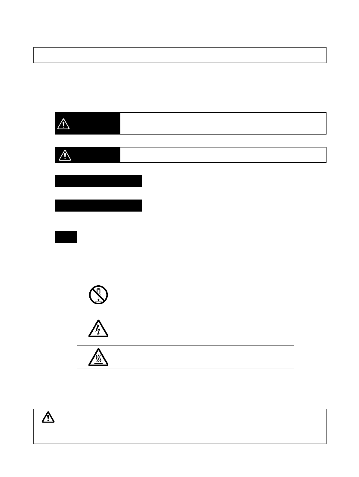
Safety-related Indications and Their Meanings
The following precautionary indications and symbols are used in this manual to aid in the safe usage of the
NT-series Support Tool for Windows (Ver. 4.j). These precautions contain important safety information.
Be sure to observe them carefully.
The indications and symbols used herein, and their meanings, are as listed below.
Indicates a potentially hazardous situation which, if not avoided, could re-
WARNING
sult in death or serious injury. Additionally, there may be severe property
damage.
Precautions for Safe Use
Indicates actions that should be done, or avoided, for the safe use of this product.
Precautions for Correct Use
Indicates actions that should be done, or avoided, to prevent operating failure or malfunction of this product, or to prevent adverse effects on the performance or functions of this product.
Note
Notes within the text of this manual indicate safety–related points and information that are equivalent in
importance to those included in the Precautions for Safe Use sections.
Symbols
Caution
Indicates a potentially hazardous situation which, if not avoided, may result
in minor or moderate injury, or property damage.
Disassembly Prohibition
Indicates prohibitions when there is a possibility of injury, such
as from electric shock, as the result of disassembly.
Electrical Shock Caution
Indicates the possibility of electric shock under specific conditions.
Indicates the possibility of injury by high temperature under
specific conditions.
WARNING
Failure to read and understand the information provided in this manual may result
in personal injury or death, damage to the product, or product failure. Please read
each section in its entirety and be sure you understand the information provided in
the section and related sections before attempting any of the procedures or operations given.
x
Page 11

TABLE OF CONTENTS
SECTION 1
Introduction to the Support Tool 1. . . . . . . . . . . . . . . . . . .
1-1 What Is Support Tool? 2. . . . . . . . . . . . . . . . . . . . . . . . . . . . . . . . . . . . . . . . . . . . . . . . . . . .
1-2 Equipment Necessary for Using the Support Tool 6. . . . . . . . . . . . . . . . . . . . . . . . . . . . . .
1-3 General Configuration of the Support Tool 7. . . . . . . . . . . . . . . . . . . . . . . . . . . . . . . . . . . .
1-4 Basic Operation Flow 21. . . . . . . . . . . . . . . . . . . . . . . . . . . . . . . . . . . . . . . . . . . . . . . . . . . . .
1-5 Menu Chart 22. . . . . . . . . . . . . . . . . . . . . . . . . . . . . . . . . . . . . . . . . . . . . . . . . . . . . . . . . . . . .
1-6 Usable Hardware Combinations 26. . . . . . . . . . . . . . . . . . . . . . . . . . . . . . . . . . . . . . . . . . . .
SECTION 2
Setting Up the Support Tool 29. . . . . . . . . . . . . . . . . . . . . . .
2-1 Before Installing the Software 30. . . . . . . . . . . . . . . . . . . . . . . . . . . . . . . . . . . . . . . . . . . . . .
2-2 Installing the Support Tool 31. . . . . . . . . . . . . . . . . . . . . . . . . . . . . . . . . . . . . . . . . . . . . . . . .
SECTION 3
Support Tool Starting-up and Exiting Procedure
and File Operation 37. . . . . . . . . . . . . . . . . . . . . . . . . . . . .
3-1 Starting-up and Exiting the Support Tool 38. . . . . . . . . . . . . . . . . . . . . . . . . . . . . . . . . . . . .
3-2 User Interface 40. . . . . . . . . . . . . . . . . . . . . . . . . . . . . . . . . . . . . . . . . . . . . . . . . . . . . . . . . . .
3-3 Operation of Screen Data (Application) File 45. . . . . . . . . . . . . . . . . . . . . . . . . . . . . . . . . . .
SECTION 4
Application Manager 65. . . . . . . . . . . . . . . . . . . . . . . . . . . . .
4-1 What Is the Application Manager? 66. . . . . . . . . . . . . . . . . . . . . . . . . . . . . . . . . . . . . . . . . .
4-2 Operating the Application Manager 67. . . . . . . . . . . . . . . . . . . . . . . . . . . . . . . . . . . . . . . . . .
SECTION 5
Screen Types 79. . . . . . . . . . . . . . . . . . . . . . . . . . . . . . . . . . . .
5-1 Types of Screens, Common Dialog Box Settings and Operations 80. . . . . . . . . . . . . . . . . .
5-2 Standard Screen 90. . . . . . . . . . . . . . . . . . . . . . . . . . . . . . . . . . . . . . . . . . . . . . . . . . . . . . . . .
5-3 Continuous/Overlapping Screens 91. . . . . . . . . . . . . . . . . . . . . . . . . . . . . . . . . . . . . . . . . . . .
5-4 Window/Keyboard Screens 94. . . . . . . . . . . . . . . . . . . . . . . . . . . . . . . . . . . . . . . . . . . . . . . .
5-5 Extended Screen 99. . . . . . . . . . . . . . . . . . . . . . . . . . . . . . . . . . . . . . . . . . . . . . . . . . . . . . . . .
5-6 Occurrence History Screen 100. . . . . . . . . . . . . . . . . . . . . . . . . . . . . . . . . . . . . . . . . . . . . . . .
5-7 Frequency History Screen 101. . . . . . . . . . . . . . . . . . . . . . . . . . . . . . . . . . . . . . . . . . . . . . . . .
5-8 Host Connect Screen (System Initializing Screen) 101. . . . . . . . . . . . . . . . . . . . . . . . . . . . . .
5-9 Password Screen 102. . . . . . . . . . . . . . . . . . . . . . . . . . . . . . . . . . . . . . . . . . . . . . . . . . . . . . . . .
5-10 Menu Screen 103. . . . . . . . . . . . . . . . . . . . . . . . . . . . . . . . . . . . . . . . . . . . . . . . . . . . . . . . . . . .
5-11 Print Format Screen 103. . . . . . . . . . . . . . . . . . . . . . . . . . . . . . . . . . . . . . . . . . . . . . . . . . . . . .
5-12 Programming Console Screen 103. . . . . . . . . . . . . . . . . . . . . . . . . . . . . . . . . . . . . . . . . . . . . .
5-13 Device Monitor Screen 104. . . . . . . . . . . . . . . . . . . . . . . . . . . . . . . . . . . . . . . . . . . . . . . . . . .
5-14 Contrast and Brightness Adjustment 104. . . . . . . . . . . . . . . . . . . . . . . . . . . . . . . . . . . . . . . . .
xi
Page 12

TABLE OF CONTENTS
SECTION 6
Element Operating Procedures 105. . . . . . . . . . . . . . . . . . . . .
6-1 Common Operation 107. . . . . . . . . . . . . . . . . . . . . . . . . . . . . . . . . . . . . . . . . . . . . . . . . . . . . .
6-2 Fixed Display 138. . . . . . . . . . . . . . . . . . . . . . . . . . . . . . . . . . . . . . . . . . . . . . . . . . . . . . . . . . .
6-3 Alarm 161. . . . . . . . . . . . . . . . . . . . . . . . . . . . . . . . . . . . . . . . . . . . . . . . . . . . . . . . . . . . . . . . .
6-4 Data Input 173. . . . . . . . . . . . . . . . . . . . . . . . . . . . . . . . . . . . . . . . . . . . . . . . . . . . . . . . . . . . . .
6-5 Lamps 194. . . . . . . . . . . . . . . . . . . . . . . . . . . . . . . . . . . . . . . . . . . . . . . . . . . . . . . . . . . . . . . . .
6-6 Numeral Display 202. . . . . . . . . . . . . . . . . . . . . . . . . . . . . . . . . . . . . . . . . . . . . . . . . . . . . . . .
6-7 Character String Display 206. . . . . . . . . . . . . . . . . . . . . . . . . . . . . . . . . . . . . . . . . . . . . . . . . .
6-8 Touch Switches 209. . . . . . . . . . . . . . . . . . . . . . . . . . . . . . . . . . . . . . . . . . . . . . . . . . . . . . . . . .
6-9 Graphs 226. . . . . . . . . . . . . . . . . . . . . . . . . . . . . . . . . . . . . . . . . . . . . . . . . . . . . . . . . . . . . . . . .
6-10 Registering Created Elements (Symbol Manager Operation) 252. . . . . . . . . . . . . . . . . . . . . .
6-11 Recipe Screen Element 261. . . . . . . . . . . . . . . . . . . . . . . . . . . . . . . . . . . . . . . . . . . . . . . . . . .
SECTION 7
Memory Table Setting 267. . . . . . . . . . . . . . . . . . . . . . . . . . . .
7-1 Common Operation 268. . . . . . . . . . . . . . . . . . . . . . . . . . . . . . . . . . . . . . . . . . . . . . . . . . . . . .
7-2 Numeral Memory Table 277. . . . . . . . . . . . . . . . . . . . . . . . . . . . . . . . . . . . . . . . . . . . . . . . . . .
7-3 Character String Memory Table (String Table) 283. . . . . . . . . . . . . . . . . . . . . . . . . . . . . . . . .
7-4 Bit Memory Table 288. . . . . . . . . . . . . . . . . . . . . . . . . . . . . . . . . . . . . . . . . . . . . . . . . . . . . . .
7-5 Extended I/O Input Table 293. . . . . . . . . . . . . . . . . . . . . . . . . . . . . . . . . . . . . . . . . . . . . . . . . .
7-6 Extended I/O Output Table 297. . . . . . . . . . . . . . . . . . . . . . . . . . . . . . . . . . . . . . . . . . . . . . . .
7-7 I/O Comment Table 298. . . . . . . . . . . . . . . . . . . . . . . . . . . . . . . . . . . . . . . . . . . . . . . . . . . . . .
7-8 F-Key Input Notify Table 307. . . . . . . . . . . . . . . . . . . . . . . . . . . . . . . . . . . . . . . . . . . . . . . . . .
7-9 Mathematical Table 308. . . . . . . . . . . . . . . . . . . . . . . . . . . . . . . . . . . . . . . . . . . . . . . . . . . . . .
7-10 Recipe Table 313. . . . . . . . . . . . . . . . . . . . . . . . . . . . . . . . . . . . . . . . . . . . . . . . . . . . . . . . . . . .
SECTION 8
Editing Graphic Data 323. . . . . . . . . . . . . . . . . . . . . . . . . . . .
8-1 Image Editor 324. . . . . . . . . . . . . . . . . . . . . . . . . . . . . . . . . . . . . . . . . . . . . . . . . . . . . . . . . . . .
8-2 Library Editor 336. . . . . . . . . . . . . . . . . . . . . . . . . . . . . . . . . . . . . . . . . . . . . . . . . . . . . . . . . . .
8-3 Mark Editor 344. . . . . . . . . . . . . . . . . . . . . . . . . . . . . . . . . . . . . . . . . . . . . . . . . . . . . . . . . . . .
SECTION 9
Example Screens 351. . . . . . . . . . . . . . . . . . . . . . . . . . . . . . . .
9-1 Example Screen Configuration 352. . . . . . . . . . . . . . . . . . . . . . . . . . . . . . . . . . . . . . . . . . . . .
9-2 Operation Flow 357. . . . . . . . . . . . . . . . . . . . . . . . . . . . . . . . . . . . . . . . . . . . . . . . . . . . . . . . . .
9-3 Creating the Sample Data 360. . . . . . . . . . . . . . . . . . . . . . . . . . . . . . . . . . . . . . . . . . . . . . . . .
SECTION 10
Quick Reference 407. . . . . . . . . . . . . . . . . . . . . . . . . . . . . . . . .
10-1 Quick Reference 408. . . . . . . . . . . . . . . . . . . . . . . . . . . . . . . . . . . . . . . . . . . . . . . . . . . . . . . . .
SECTION 11
Data Communications with a PT 429. . . . . . . . . . . . . . . . . . .
11-1 Preparation for Data Communications with a PT and Data Communication Procedure 430.
11-2 Communication Setting at the Support Tool 432. . . . . . . . . . . . . . . . . . . . . . . . . . . . . . . . . . .
11-3 Sending (Downloading) the Data 433. . . . . . . . . . . . . . . . . . . . . . . . . . . . . . . . . . . . . . . . . . . .
11-4 Receiving (Uploading) Data 436. . . . . . . . . . . . . . . . . . . . . . . . . . . . . . . . . . . . . . . . . . . . . . .
11-5 Receiving (Uploading) the History Record 439. . . . . . . . . . . . . . . . . . . . . . . . . . . . . . . . . . . .
11-6 Setting and Reading the Date and Time 440. . . . . . . . . . . . . . . . . . . . . . . . . . . . . . . . . . . . . .
xii
Page 13

TABLE OF CONTENTS
SECTION 12
Making Reports 443. . . . . . . . . . . . . . . . . . . . . . . . . . . . . . . . .
12-1 Report Types 444. . . . . . . . . . . . . . . . . . . . . . . . . . . . . . . . . . . . . . . . . . . . . . . . . . . . . . . . . . . .
12-2 Printing Reports 451. . . . . . . . . . . . . . . . . . . . . . . . . . . . . . . . . . . . . . . . . . . . . . . . . . . . . . . . .
12-3 Displaying the Print Image (Preview) 458. . . . . . . . . . . . . . . . . . . . . . . . . . . . . . . . . . . . . . . .
12-4 Outputting the Screen Image 459. . . . . . . . . . . . . . . . . . . . . . . . . . . . . . . . . . . . . . . . . . . . . . .
Appendices
A Data Conversion 463. . . . . . . . . . . . . . . . . . . . . . . . . . . . . . . . . . . . . . . . . . . . . . . . . . . . . . . . . . .
B System Installer Operation 487. . . . . . . . . . . . . . . . . . . . . . . . . . . . . . . . . . . . . . . . . . . . . . . . . . .
C NT Transfer Utility 493. . . . . . . . . . . . . . . . . . . . . . . . . . . . . . . . . . . . . . . . . . . . . . . . . . . . . . . . .
D Translation Support Utility 501. . . . . . . . . . . . . . . . . . . . . . . . . . . . . . . . . . . . . . . . . . . . . . . . . . .
E Tables of Functions of PT Models 517. . . . . . . . . . . . . . . . . . . . . . . . . . . . . . . . . . . . . . . . . . . . .
F Limits on Numbers of Elements 537. . . . . . . . . . . . . . . . . . . . . . . . . . . . . . . . . . . . . . . . . . . . . . .
G New Functions of Support Tool Ver.4.1 541. . . . . . . . . . . . . . . . . . . . . . . . . . . . . . . . . . . . . . . . .
H New Functions of Support Tool Ver.4.6 543. . . . . . . . . . . . . . . . . . . . . . . . . . . . . . . . . . . . . . . . .
I New Functions of Support Tool Ver.4.7 545. . . . . . . . . . . . . . . . . . . . . . . . . . . . . . . . . . . . . . . . .
J New Functions of Support Tool Ver.4.8 547. . . . . . . . . . . . . . . . . . . . . . . . . . . . . . . . . . . . . . . . .
K Error Messages 549. . . . . . . . . . . . . . . . . . . . . . . . . . . . . . . . . . . . . . . . . . . . . . . . . . . . . . . . . . . .
L Shortcut Keys 555. . . . . . . . . . . . . . . . . . . . . . . . . . . . . . . . . . . . . . . . . . . . . . . . . . . . . . . . . . . . .
M Connecting Cable Specifications 557. . . . . . . . . . . . . . . . . . . . . . . . . . . . . . . . . . . . . . . . . . . . . .
N Keycode Tables and Conversion Rule 559. . . . . . . . . . . . . . . . . . . . . . . . . . . . . . . . . . . . . . . . . .
Index 569. . . . . . . . . . . . . . . . . . . . . . . . . . . . . . . . . . . . . . . . . .
Revision History 575. . . . . . . . . . . . . . . . . . . . . . . . . . . . . . . . .
xiii
Page 14

Page 15

Organization of the Manual, and How to Use It:
The related manuals are listed below.
* The final digit of the manual number is the revision code.
For operating the Support Tool
NT-series Support Tool for Windows Operation Manual (V061-E1-2):
S
Details on the operating procedure, settings, etc., of the Support Tool can be
displayed on the screen in the form of online help information. Normal operation
can be carried out by following this help information.
When you are unsure of the operating procedure while using the Support Tool, or
you need to check detailed settings, refer to this manual.
The explanations in this manual center on the Support Tool itself. It does not
include detailed explanations on the operation of the PT. Therefore, refer to the
following manuals also.
This manual also explains the operation of NT Transfer Utility which is
exclusively used for downloading and uploading the screen data.
The NT-series Support Tool for Windows (Ver. 4.j) can be used with the latest
direct access versions of the following PT models. Details are given in this manual.
This manual. . . . . . . . . . . . . . . . . . . . . . . . . . . . . . . . . . . . . . . . . . . . . . . . . . . . . . .
NT11, NT11S, NT20, NT20S, NT21, NT30, NT30C, NT31, NT31C, NT600S,
NT620S, NT620C, NT625C, NT631, NT631C
For information on PT functions, operations, and restrictions
S NT11 Programmable Terminal User’s Manual (V084-E1-j)
S NT11S Programmable Terminal User’s Manual (V029-E1-j)
S NT20 Programmable Terminal User’s Manual (V091-E1-j)
S NT20S Programmable Terminal Operation Manual (V020-E1-j)
S NT600S Programmable Terminal Operation Manual (V022-E1-j)
S NT30/NT30C Programmable Terminal Operation Manual (V034-E1-j)
S NT620S/NT620C/NT625C Programmable Terminal Operation Manual
(V033-E1-j)
S NT21 Programmable Terminal Setup Manual (V068-E1-j)
S NT31/31C Programmable Terminal Setup Manual (V062-E1-j)
S NT631/631C Programmable Terminal Setup Manual (V063-E1-j)
S NT21/31/631 Programmable Terminal Reference Manual (V069-E1-j)
These manuals contain full descriptions of PT functions, operations, and
restrictions.
For information on the functions and operations of the PC
S Operation manual for each PC
xv
Page 16

When you need information about the operations, functions, etc., of the PC, refer
to the operation manual for the PC, advanced function unit, or communication
unit being used.
Description of NT31, NT31C, NT631 and NT631C
There are two types of the NT31, NT31C, NT631, and NT631C, models with the
suffix “-Vj” and models without the suffix “-Vj.” In this manual, they are written
as “NT31, NT31C, NT631 and NT631C” collectively when it is not necessary to
classify them. However, they are written separately as “NT31, NT31C, NT631,
and NT631C with -Vj” and “NT31, NT31C, NT631, and NT631C without -Vj”
when it is necessary to classify them. (The system program version will be indicated as “NT31, NT31C, NT631 and NT631C with (System Ver. 3.1),” if required.)
The system programs of the NT31, NT31C, NT631, and NT631C with “-V2” or
“-V3” (System Ver. 3.1/4.1) are supplied by NT-series Support Tool for Windows
(Ver.4.j). System Ver. 4.1 is supported only by NT31, NT31C, and NT631C
models with “-V3.” It cannot be installed to upgrade the NT31, NT31C, NT631, or
NT631C below “-V3.” It is possible to upgrade NT31, NT31C, NT631 and
NT631C models without “-V2” to System Ver. 3.1 by installing the new system. In
this case, however, the functions indicated below cannot be used even though
other functions can be used in the same way as the models with “-V2.”
S 32-dot font
For details of 32-dot font, refer to Settings for text display in NO TAG Setting
Properties. Note that smoothing is not performed for 32-dot font.
For details of font types, refer to Font Type in NO TAG Operation of Screen Data
(Application) File and Appendix K.
xvi
Page 17

SECTION 1
Introduction to the Support Tool
This section is designed for users to utilize the efficient usage of Support Tool.
Discussed in this section are what you can do using the Support Tool and the specifications and functions of Support Tool.
1-1 What Is Support Tool? 2. . . . . . . . . . . . . . . . . . . . . . . . . . . . . . . . . . . . . . . . . . . . . . . . . . . . .
1-2 Equipment Necessary for Using the Support Tool 6. . . . . . . . . . . . . . . . . . . . . . . . . . . . . . . .
1-3 General Configuration of the Support Tool 7. . . . . . . . . . . . . . . . . . . . . . . . . . . . . . . . . . . . .
1-3-1 Outline of Screen Data 7. . . . . . . . . . . . . . . . . . . . . . . . . . . . . . . . . . . . . . . . . . . . . .
1-3-2 Correspondence to PC (PLC) Data 11. . . . . . . . . . . . . . . . . . . . . . . . . . . . . . . . . . . .
1-3-3 Tables 15. . . . . . . . . . . . . . . . . . . . . . . . . . . . . . . . . . . . . . . . . . . . . . . . . . . . . . . . . . .
1-3-4 Types of Screens 18. . . . . . . . . . . . . . . . . . . . . . . . . . . . . . . . . . . . . . . . . . . . . . . . . .
1-4 Basic Operation Flow 21. . . . . . . . . . . . . . . . . . . . . . . . . . . . . . . . . . . . . . . . . . . . . . . . . . . . . .
1-5 Menu Chart 22. . . . . . . . . . . . . . . . . . . . . . . . . . . . . . . . . . . . . . . . . . . . . . . . . . . . . . . . . . . . . .
1-6 Usable Hardware Combinations 26. . . . . . . . . . . . . . . . . . . . . . . . . . . . . . . . . . . . . . . . . . . . . .
1-6-1 Applicable PT 26. . . . . . . . . . . . . . . . . . . . . . . . . . . . . . . . . . . . . . . . . . . . . . . . . . . .
1-6-2 Communication Method for Each PT Model 27. . . . . . . . . . . . . . . . . . . . . . . . . . . .
1
Page 18

1-1 What Is Support Tool?
The NT-series Support Tool for Windows (Ver. 4.) (hereafter referred to as the
Support Tool) is application software that runs on Windows 95, 98, NT4.0, 2000,
or XP and was developed to create the screen data for programmable terminals
(PTs).
Since the Support Tool has been developed to use the graphical interface and
run under the operation environment of Windows, persons not familiar with the
Support Tool can create the screen data of the programmable terminal without
difficulties.
The Support Tool can create the screen data for the following models of PT.
NT11, NT11S, NT20/NT20S, NT30, NT30C, NT600S, NT620S, T620C/NT625C
NT21, NT31, NT31C, NT631, NT631C
The screen data created using the Support Tool consists of the objects shown in
the following page.
1-1SectionWhat Is Support Tool?
2
Page 19
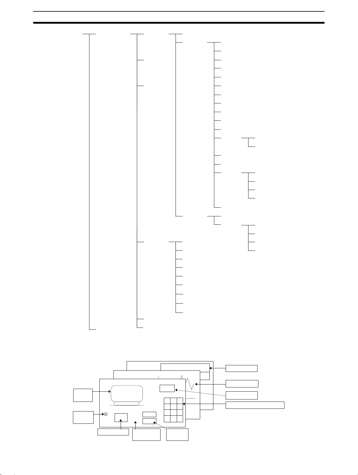
1-1SectionWhat Is Support Tool?
by the Support Tool
Screen DataData created
Symbol Data
Screen 1 Screen Properties
Display
Object
Screen 2
Screen 3
.............
Input
Object
Table Numeral Table
String Table
Bit Memory Table
Extended I/O Input Table
Extended I/O Output Table
I/O Comment Table
F-key input Notify Table
Mathematical Table
Recipe Table
System Memory
Direct Access
Arc
Circle
Sector
Polyline
Polygon
Rectangle
Text
Tiling
Image Object
Library Object
Mark
Lamp
Numeral Display
String Display
Graph
Alarm List/Alarm History
Touch Switch
Input
Setting
Standard Lamp
Image Lamp
Bar Graph
Analogue Meter
Broken-line Graph
Trend Graph
Numeral Input
String Input
Thumbwheel Switch
Recipe
Fixed
display
Lamp
display
Screen 2
Screen 1
Touch switch
Menu
Screen N
SV
PV
Fixed
display-text
Temp. Alarm 10:00
Temp. Alarm 11:01
ABCD
7 8 9
4
5 6
1
2 3
SP 0 CR
Numeral
display
Alarm display
Graph display
String Display
Data input (numeral input)
3
Page 20

Product Configuration
1-1SectionWhat Is Support Tool?
The NT-series Support Tool for Windows (Ver. 4.) consists of the following software and data.
Support Tool
Model number
NT-ZJCAT1-EV4 For IBM PC/AT or compatible, media: CD-ROM
Keyboard tenkey library
Color pallette symbols (Library of parts for filling with color models)
System Installer (to replace PT system program)
NT20 system program
System program for NT31, NT31C, and NT631C with “-V3”
Original NT30/620 system program
NT Screen Data Transfer Utility
This utility is for uploading and downloading PT data using mmi screen data
files. Refer to Appendix C NT Transfer Utility for details.
Samples
Lamp/touch switch parts library
This parts library contains the image library with lamps and touch switches
incorporated into it as a mmi image data file. Refer to 3-3-7 Using Method of
Parts Collection for details. (The folder containing the parts library list in the
samples folder also contains HTML files with operating methods and a parts
list.)
Specifications
Sample screen data
This screen data is provided only as a sample. Operation may not be as
expected when this data is transferred to a PT and used for communications
with a PLC.
Symbol manager ISO symbol data
Refer to 6-10 Registering Created Elements (Symbol Manager Operation) for
details.
Main Differences of V4.1
Following changes are made for NT-series Support Tool for Windows to improve
operational efficiency and to support new functions added for NT31, NT31C,
NT631 and NT631C with “-V2” or “-V3” (System Ver. 3.1 or 4.0). Refer to Appen-
dix G New Functions of Support Tool Ver. 4.1.
NT31, NT31C, NT631, NT631C new system program support
System program for the NT31, NT31C, NT631, and NT631C has been upgraded
to Ver. 3.1/Ver. 4.0, so the following functions are now supported. System program version 4.0 is used only with the NT31, NT31C, NT631, and NT631C. New
system program is supplied with Support Tool Ver. 4.1.
CS/CJ-series PC (PLC) memory area support
Recipes
Interlocks
Mathematical table
4
Page 21

NT30/620-compatible mode
Multiple line labels
ON/OFF state labels
Numeral display/string display labels
Device monitor screens
Contrast & brightness adjustment screens
Addition of NT Translation Support Utility
The Translation Support Utility is software that helps in translating a language to
another supported language.
For details, refer to Appendix D NT Translation Support Utility.
I/O comments importing from TAB-delimited text file
For details, refer to 7-7-4 Importing I/O Comments from Tab-delimited Text Files.
Centering the Labels of Lamp and Touch Switches
Only horizontal direction could be centered in previous versions. In this version,
the labels of lamp/touch switches can be centered in both vertical and horizontal
directions.
1-1SectionWhat Is Support Tool?
For details, refer to 6-1-9 Centering the Label of Lamp and Touch Switch.
The Data input string in a string input function touch switch (Only for NT31/631)
The label was used for the input data string in previous versions. In this version, a
different string from the label can be specified as the data input string.
For details, refer to 6-8-3 Character String Input Touch Switch.
Launch the system installer
It is possible to launch the system installer from [Connect]–[Launch System Installer] in the menu bar.
Addition of NT30/620 series system programs
The system programs for NT30/620 are included.
Main Differences of V4.6
NT21 New System Program Support
Starting with NTST-EV4.6, the NTST supports creating screen data for the
NT21.
NT31-V2 (System Ver. 3.1) data and NT21 data can be converted for mutual
compatibility.
NT20 data can be converted to NT21 data.
NTST-EV4.6 can transfer screen data to the NT21 in high-speed mode.
Refer to NT21/31/631 Reference Manual for details.
Pick I/O Comments from a CX-Server Database
I/O name in CX-Server data can be used as PT I/O comment.
When a PLC address is defined in the dialog, an I/O comment can be picked up
from CX-Server PLC point data in a cdm file. The “Pick CX-Server point” button
is enabled only when CX-Server is installed.
When the I/O comment table is edited, multiple I/O comment data can be picked
up from CX-Server PLC point data in the cdm file. The “Import” button is enabled
only when CX-Server is installed.
5
Page 22

Each I/O name will be imported as a PT I/O comment within 16 characters.
Property Dialog for Grouped Objects
Grouped object attributes can be edited by double-clicking or right-clicking to
display the properties for grouped objects. The properties show the tree the objects included in the group. Choose each object in the tree to edit the structure.
Preview in Symbol Manager
Registered symbols can be previewed on the symbol manager. Previous symbols can be previewed after they are copied onto the NTST-EV4.6 screen and
copied back to symbol manager to create preview images. Or, those symbols
can be reused without preview as they are.
Copying Image/Library/Mark with contents
When copying Image/Library/Mark objects, NTST-EV4.6 will copy them with
contents and registered them in each table. If the same code is already used in
the table, the NTST will display a dialog to show the next unused number as a
substitute.
The functionality does not recursively apply to references in the Image/Library/
Mark object. For example, when copying a library object that refers to library
entry, and the content of the entry contains text with a mark reference, then the
corresponding mark content will be ignored. It also does not apply to when
screens are copied in Application Manager for pasting into a second instance of
NTST.
1-2SectionEquipment Necessary for Using the Support Tool
Main Differences of V4.7
NT11-V1 New System Program Support
Starting with NTST-EV4.7, the NTST supports creating screen data for the
NT11-V1.
NT11S data can be converted to NT11-V1 data.
Refer to NT11 User’s Manual for details.
Supported Windows OS
Starting with NTST-EV4.7, the NTST supports Windows Me, 2000 (Professional
Edition), and XP (Pro/Home Edition).
Automatically Adjusted Screen Size when Editing Starts
In response to the high resolution of personal computers recently, the screen
size is now automatically enlarged when editing screens.
Main Differences of V4.8
Support for the NT20 PTs has been added to version 4.8 of the NT-series Support
Tool for Windows.
• The NT20 system program has been added.
• The system installer has been updated to support the NT20 system program.
1-2 Equipment Necessary for Using the Support Tool
The following indicates the equipment necessary for using the Support Tool.
Hardware
6
Recommended CPU
Pentium 100 MHz or faster CPU
Personal Computer
Use an IBM personal computer or 100% compatible.
Recommended Memory
Page 23

32 Mbytes minimum
S Free area in hard disk
At least 52 Mbytes is required to install everything.
The following options can be selected at installation:
Support Software: Approx. 23 Mbytes
System installer
Only system installer: Approx. 8 Mbytes
With support programs: Approx. 30 Mbytes
Samples (parts, parts list, etc.): Approx. 40 Mbytes
S CD-ROM drive
At least one drive is required if the Support Tool is provided on CD-ROM.
S Display
VGA compatible display
When creating screen data for a PT that has a color display, a color display is
required.
When the resolution setting of desktop area is low (lower than 640 480), part
of the window of Support Tool may stick out of the screen. In this case, change
the resolution setting of desktop area to the higher one with the control panel
property of Windows.
1-3SectionGeneral Configuration of the Support Tool
S Mouse
Serial mouse or bus mouse
Operating system
The NT-series Support Tool runs on Microsoft Windows 95, Microsoft Windows
98, and Microsoft Windows NT 4.0. Version 4.05 or higher of the NT-series Support Tool also runs on Microsoft Windows 2000 and Microsoft Windows XP.
Version 4.80 or higher of the NT-series Support Tool also runs on Microsoft Windows Vista and Microsoft Windows 7.
The NT-series Support Tool will not run on Windows 3.1.
Operation on a 64-bit OS or server OS is also not supported.
Device necessary for transmitting screen data
S RS-232C cable
For cable specifications, refer to Appendix K Connecting Cable Specifications.
1-3 General Configuration of the Support Tool
1-3-1 Outline of Screen Data
The screen data of the Support Tool consists of multiple screens that are linked
with each other.
Screens are managed by screen numbers. The range of usable screen numbers
varies according to the type of the PT connected to the Support Tool.
The screen display is switched by pressing a touch switch or giving an instruction
from the PC (PLC).
7
Page 24

Display objects
1-3SectionGeneral Configuration of the Support Tool
PT Model Range of Screen Numbers
NT11/NT11S 1 to 25
NT20/NT20S 1 to 250, 256 to 500
NT600S 1 to 1000
NT30/NT30C
NT620S/NT620C/NT625C
NT21 1 to 3999, 9000, 9001, 9002, 9020
NT31/NT31C/
NT631/NT631C
On a screen, a variety of objects can be arranged as desired.
The following objects are used to create a screen.
Display objects are drawn on a screen and do not have an input function.
Display objects are classified into two kinds: Objects that are always displayed in
the same status, and those that change according to the status of the PT or the
PC (PLC).
1 to 1899, 1900 to 1979 1980 to 1999, 2000
1 to 3999, 9000, 9001, 9002, 9020 to 9023,
9030
Input objects
Objects having code numbers
Input objects are objects that allow input by operation at the PT. Touch switches
and input fields for numerals and strings are examples of input objects.
These objects are created using an exclusive editor.
They are registered with a code number so that they can be used in different positions and different screens.
Library data
A drawing created as a fixed display is registered as library data so that it can
be used multiple positions and screens.
The library editor is used to create library data.
Image data
Image data are objects used to display bit map data on the screen.
An image editor or bit map editor (running on Windows 95, 98, NT 4.0, 2000, or
XP) available on the market is used to create image data.
Marks
Marks are used to display special characters and symbols. These objects can
be handled as characters.
The mark editor is used to create marks.
Registering created objects (symbol manager)
The efficiency of use of created objects can be increased by reusing them in other screen data or by registering objects that will be used frequently.
The symbol manager is provided to register created objects.
8
Page 25
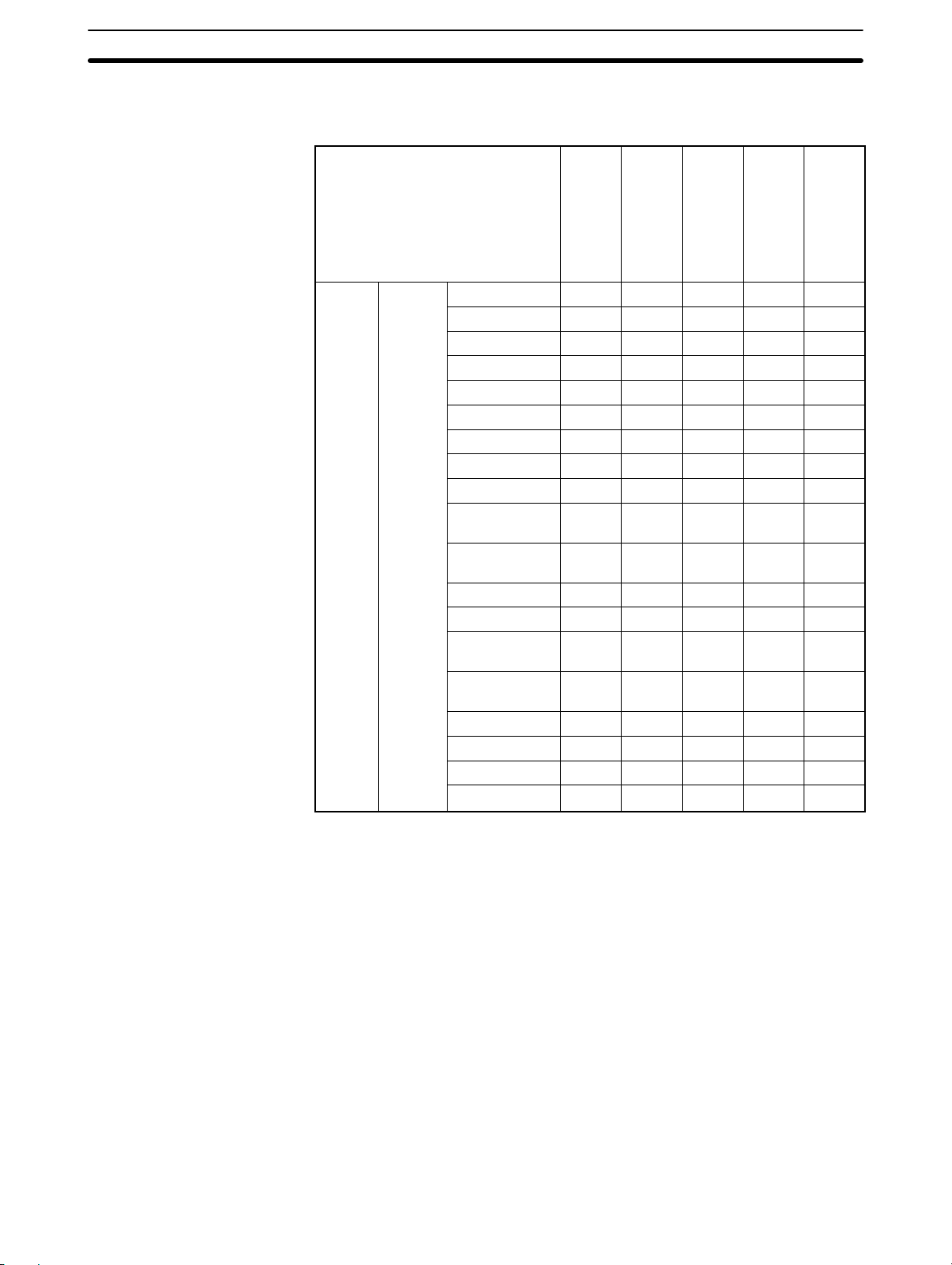
Objects that can be used
1-3SectionGeneral Configuration of the Support Tool
The table below shows that objects can be used with particular PT models.
Objects Display
Object
NT11S
/NT11
Arc – –
Circle –
Sector – –
Polyline –
Polygon – –
Rectangle – –
Text
Tiling –
Standard Lamp –
Image/Library
Lamp
Numeral
Display
String Display
Bar Graph
Broken-line
Graph
Analogue Me-
ter
Trend Graph – –
Alarm List – –
Alarm History – –
Recipe
NT20/
NT20S
NT600
– –
– –
– – –
– – –
NT30
NT30C
NT620
S
S
NT620
C
NT625
C
NT21 NT31
NT31C
NT631
NT631
C
*1
*3
: Can be used.
*1
: Can be used only with models with “-V1” and above.
*2
: Only use is insertion into character strings.
*3
: Can be used only with models ”-V2 (System Ver.3.1) and above.
9
Page 26
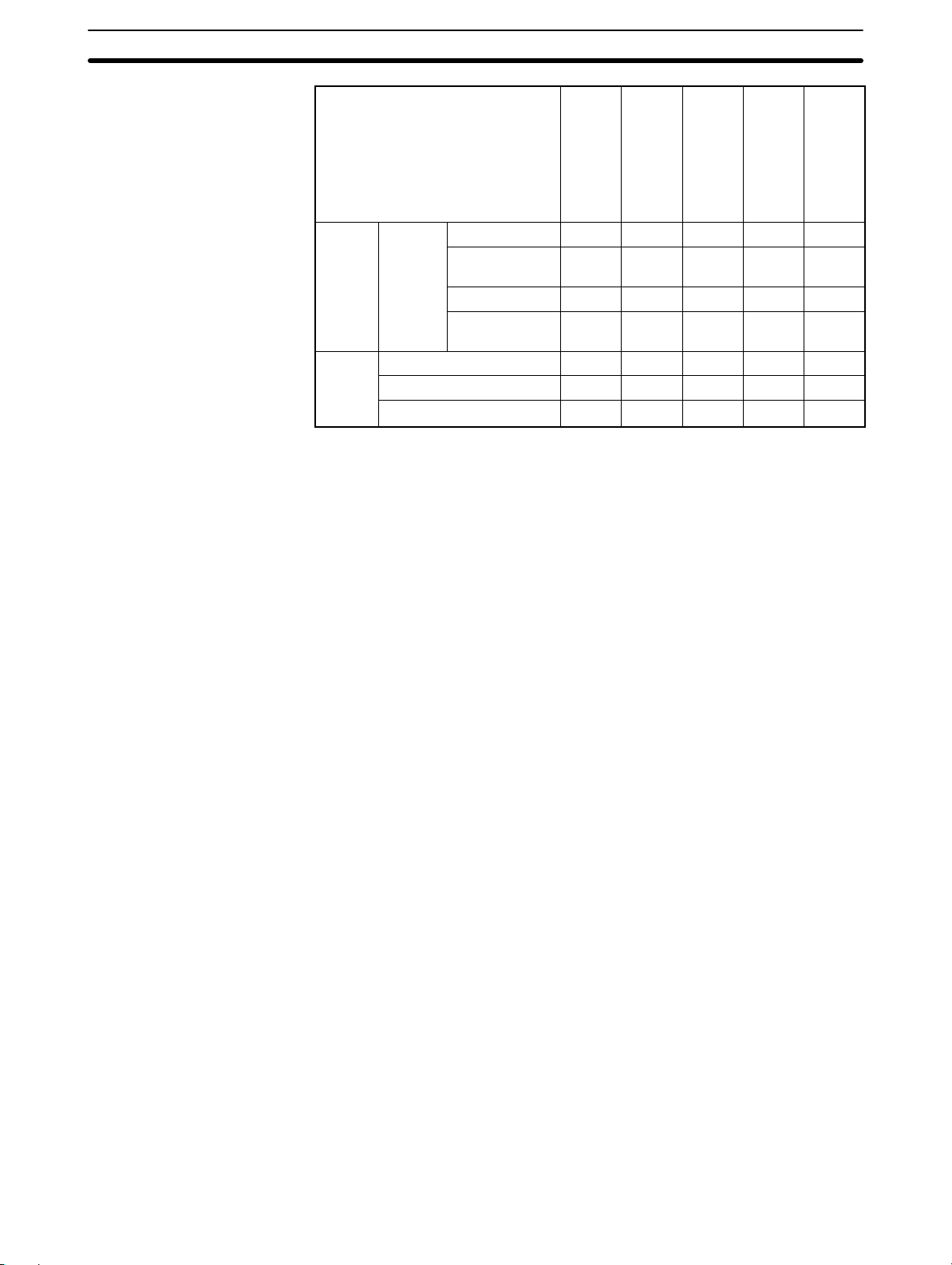
1-3SectionGeneral Configuration of the Support Tool
j
Object
Objects Input
Objects
Library
Type
Ob
Image Display – –
Library Display – –
ect
Mark
NT11S
/NT11
Touch Switch –
Numeral
Input
String Input – –
Thumbwheel
Switch
NT20
NT600
S
–
*2
*2
: Can be used.
*1
: Can be used only with models with “-V1” and above.
*2
: Only use is insertion into character strings.
NT30
NT30C
NT620
S
NT620
C
NT625
C
NT21 NT31
NT31C
NT631
NT631
C
10
Page 27
1-3-2 Correspondence to PC (PLC) Data
PT (N
l table)*1
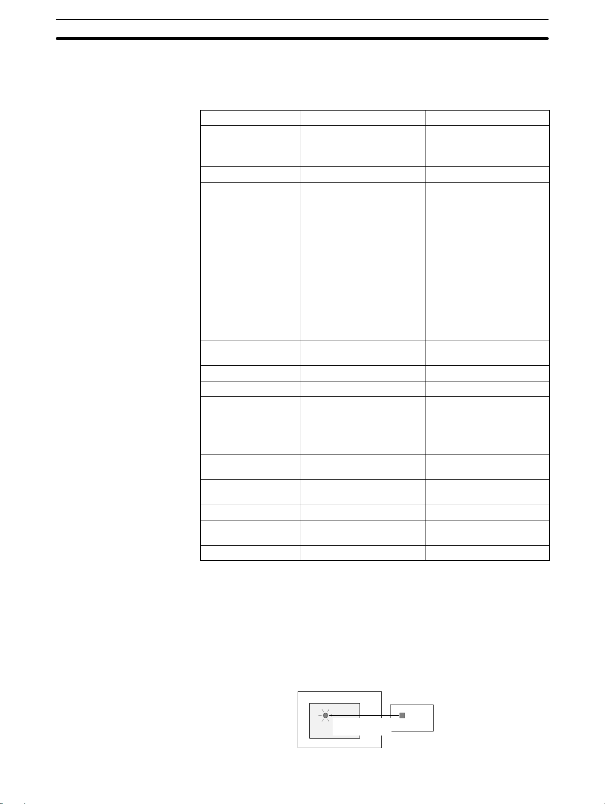
The following table shows objects that are capable of transmitting data with PC
(PLC) to execute processing such as updating the screen display.
Object Input Output
Standard Lamp PC (PLC) (bit address)
PT (String table)*1
Image/Library Lamp PC (PLC) (Bit address)
Touch Switch PC (PLC)
(bit address for lamp)
PC(PLC) (bit address for interlock) *1
PT (Numeral table) *1
PT (String table) *1
Thumbwheel Switch PC (PLC) (bit address for in-
terlock) *1
Numeral Display PT (Numeral table) –
String Display PT (String table) –
Bar Graph
Analogue Meter
Broken-line Graph
Trend Graph
Numeral Input PC (PLC) (bit address for in-
String Input PC (PLC) (bit address for in-
Alarm History PT (Bit Memory table) PT (Alarm History)
Alarm List PT (Bit Memory table) String Display
Recipe Object PC (PLC) (Word address) PC (PLC) (Word address)
PT (Numeral table) –
terlock) *1
terlock) *1
umera
1-3SectionGeneral Configuration of the Support Tool
–
*
Notify Bit (bit address)
Switch Screen
Input key-Window/Keyboard
Window Move
(Can be used only on Window Screen)
Copy Setting
(Numeral, String table)
Input key - Control
Input key - String
Cursor Move
Print Screen
PT (Numeral table)
PT (Numeral table)
PT (String table)
Image/Library Display
*1: For the NT21 and the NT31, NT31C, NT631, and NT631C with “-V2” or “–V3,”
only for numeral display or string display for labels.
*2: For the NT21 and the NT31, NT31C, NT631, and NT631C with “-V2” or “–V3,”
only when using the interlock function.
Operation of changing display objects
Lamp display
The lamp is turned ON (OFF) when the specified PC (PLC) bit goes ON (OFF).
Screen
Lamp lights when
bit comes ON
PC (PLC)
Bit address
11
Page 28
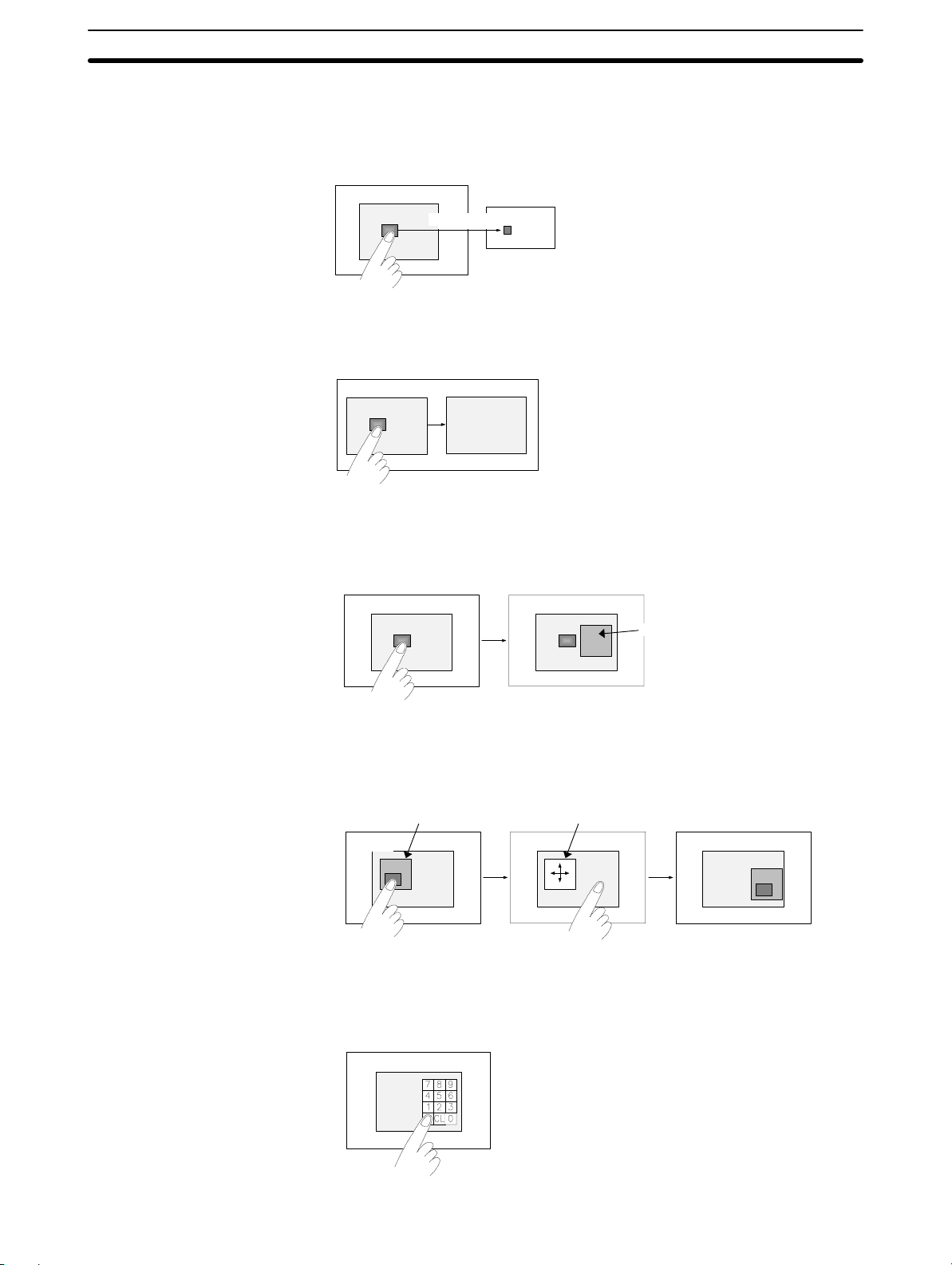
Touch switch – Notify Bit
The specified PC (PLC) bit goes ON (OFF) when the switch area is pressed.
1-3SectionGeneral Configuration of the Support Tool
Screen
Notification
PC (PLC)
Bit address
Touch switch – Switch Screen
The display screen is switched to another when the switch area is pressed.
Screen A
Screen B
Touch switch – Input Key - Window/Keyboard
A window (Keyboard Screen) pops up in the screen when the switch area is
pressed.
Screen
Screen
Window (Keyboard)
Touch switch – Window Move
The window is moved by touch panel operation when the switch area is
pressed.
Window
Screen
Window in a moving status
Screen
Screen
Touch switch – Input key - Control
When the switch area is pressed, the processing assigned to the specified control code is executed.
Screen
12
Page 29
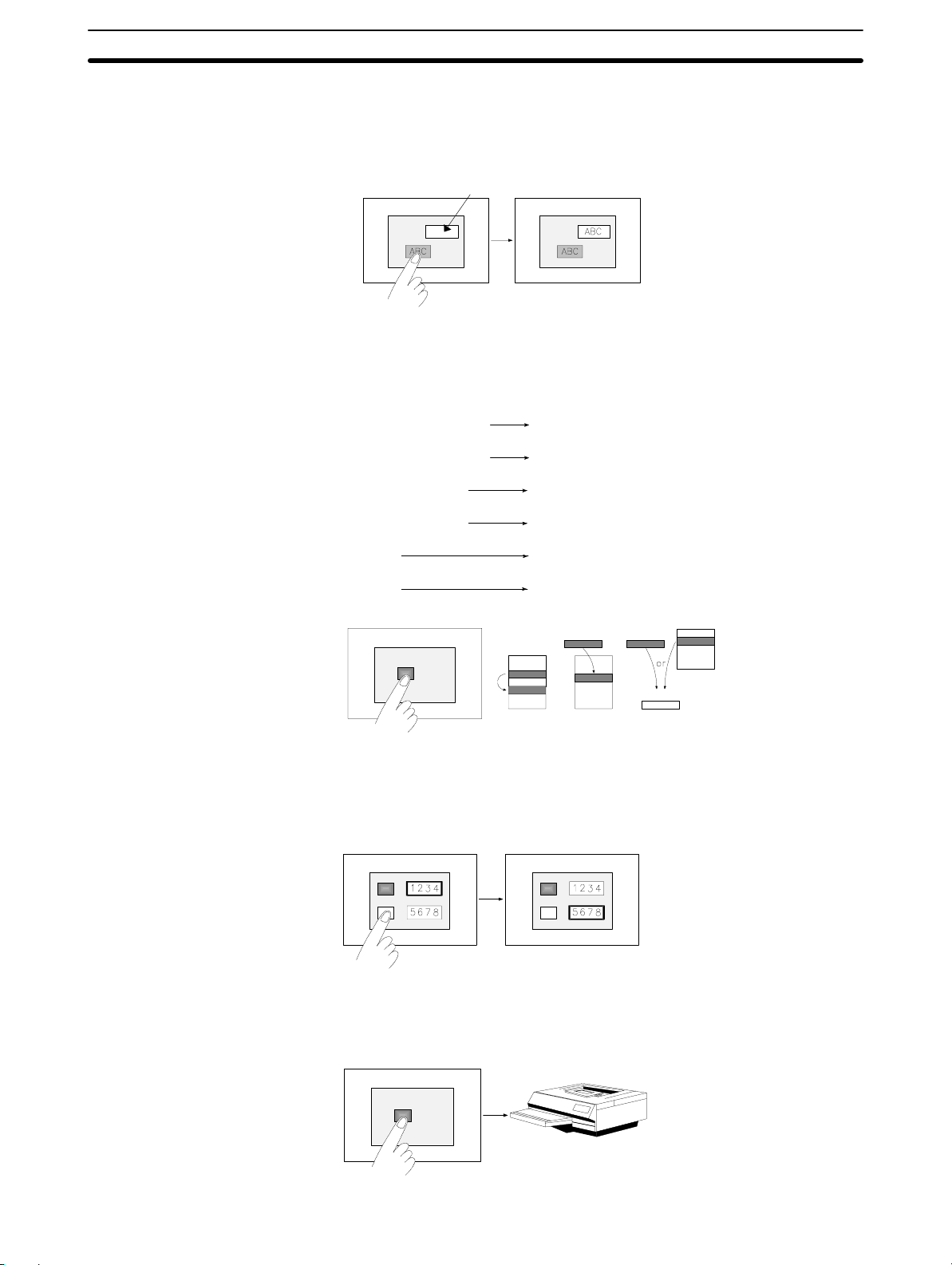
Touch switch – Input Key - String
When the switch area is pressed, the characters of the label set for the switch
are displayed in the string input field and stored in the string table.
String input field
ScreenScreen
Touch switch – Copy Setting
When the switch area is pressed, data is copied. The following types of copying
can be designated.
1-3SectionGeneral Configuration of the Support Tool
Data in Numeral table
Data in Numeral table
Data in String table
Data in String table
Constant
Constant
Screen
Numeral table
Numeral Input field
String table
String Input field
Numeral table
Numeral Input field
Data
Data
Input box
Touch switch – Cursor Move
The cursor moves from Numeral Input to Numeral Input fields when the switch
area is pressed.
ScreenScreen
Touch switch – Print Screen
A hard copy of the screen will be printed when the switch area is pressed.
Screen
13
Page 30
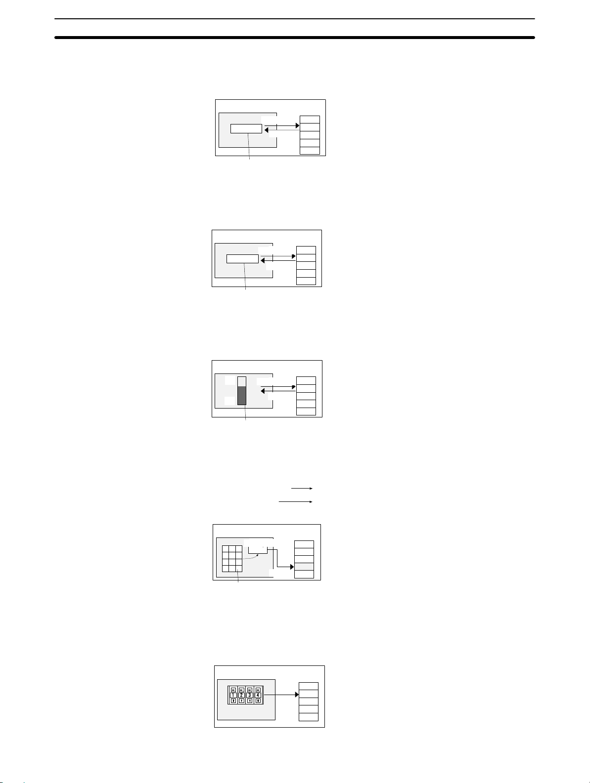
Numeral display
The data in a Numeral table will be displayed.
1-3SectionGeneral Configuration of the Support Tool
Display
Numeral
table
1234
Screen
Reference
1 2 3 4
Numeral display
String display
The string display object displays the data in a string entry.
Display
String
table
ABC
Screen
A B C
String display
Reference
Graph display
The graph display object displays the data in a numeral table entry.
Display
Numeral
table
60
Screen
100
0
Reference
Bar graph display
Data Input – numeral input and string input
These input objects write data into a table.
Numeral
table
50
Numeral Table
String Table
Numeral Input field
String Input field
Screen
Input field
50
Writing
Numeral data input
Data Input – Thumbwheel switch
The Thumbwheel Switch object stores the numeric values to a numeral table
entry through transaction of Thumbwheel Switch.
Screen
Numeral
table
1234
14
Page 31
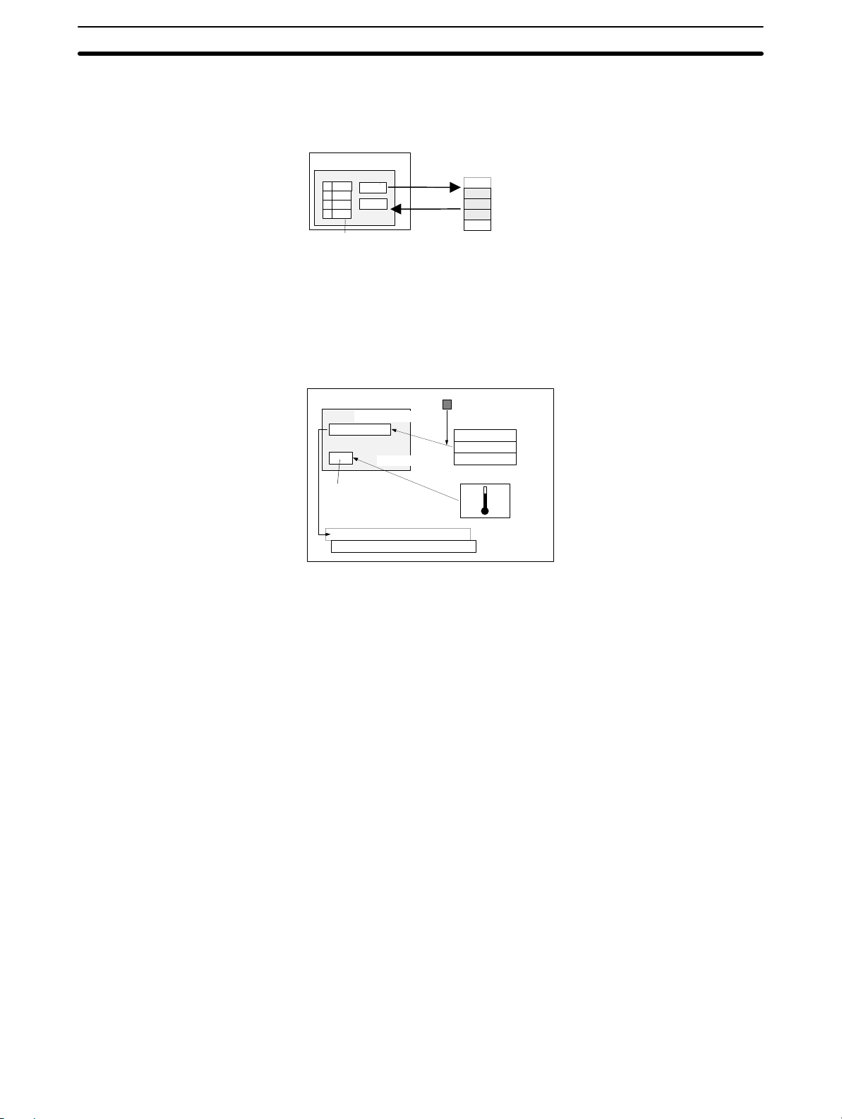
Data Input – Recipe
The recipe object reads/writes numeric values that were set using NTST from/
to the PC (PLC) when the write/read touch switch is pressed.
1-3SectionGeneral Configuration of the Support Tool
Screen
Write
Read
Recipe
PC (PLC)
10
25
315
Alarm
When a bit in a bit memory table is ON (OFF), the object displays the data in a
string table entry and stores it in the alarm history.
When the displayed data of the string table is touched, the object displays
image/library data, switches the screen to the specified screen.
Alarm list display
Temp .Alarm
Touch display
Library
data
Alarm history display
Temp. Alarm 96/11/06 16:02
Pres Alarm 97/01/06 18:25
Bit memory table
String table
Temp. Alarm
Image/Library table
1-3-3 Tables
Reference: If an “Indirect Reference” is used with image/library data, data to be displayed
can be changed according to the change in the contents of numeral table. (The
NT21 and NT31, NT31C, NT631, NT631C with System Ver. 2.1 and above only.)
Reference: The NT31, NT31C, NT631, and NT631C with “-V2” or “–V3” provide an interlock
function that can be used to enable/disable operations or inputs using touch
switches, numeral inputs, string inputs,or thumbwheel switch based on the status of specific bits in the PLC.
Tables are areas secured in the PT to store data such as numeral data and character string data. They are used to share data for the functions assigned to objects and communicate with a PC (PLC).
If a word address of a PC (PLC) is set in a table, data communication processing
between the PT and PC (PLC) is executed automatically in predetermined
cycles.
The following types of tables are provided.
Numeral table
String table
Bit memory table
Extended I/O Input table
Extended I/O Output table
I/O Comment table
15
Page 32

1-3SectionGeneral Configuration of the Support Tool
F-key Input Notify table
Mathematical table
Recipe Table
The number of memory table entries varies according to the model of PT connected.
Numeral
table
String
table
Bit
Memory
table
Extended
I/O Input
table
Extended
I/O Output
table
F-key Input Notify
table
Mathematical
table
Recipe
table
or
NT620S
NT620C
NT625C
512
or
1000
256
or
1000
NT21
512,
1000,
or
2000
256,
1000
or
2000
256
or
1000
NT11S/
NT11
128 128 512
128 128 256
NT20/N
T20S
– – – 256 256
– – – 64 – – –
– – – 64 – – –
4 – – – – – –
– – – – – 256
– – – – – 200 200
NT600S
NT30
NT30C
512
1000
256
or
1000
NT31
NT31C
NT631
NT631C
512,
1000,
or
2000
256,
1000
or
2000
256
or
1000
*1
256
*2
Numeral Table
String Table
Bit Memory Table
16
*1
: This option is available only for V2 and above.
*2
: This option is available only for V2 (System Ver.3.1) and above.
The Numeral table stores numeral data.
This table is set when using Numeral Display objects, Graph objects, and Nu-
meral Data Input.
For details of table setting, refer to 7-2 Numeral Memory Table.
The String table stores text data.
This table is set when String Display object and String Input object are used.
For details of table setting, refer to 7-3 Character String Memory Table (String
Table).
The Bit Memory table stores status of a PC (PLC) memory bit.
This table is set when using the alarm list/history function.
Page 33

Extended I/O Input Table
Extended I/O Output Table
I/O Comment Table
1-3SectionGeneral Configuration of the Support Tool
It is also used when switching the screen by the operation at the PC (PLC).
For details of table setting, refer to 7-4 Bit Memory Table.
The Extended I/O Input table sets the usage of input terminals of an extended
I/O unit (e.g., B7A Unit).
For the individual input terminals, a function is set or a PC (PLC) bit to be referenced is allocated.
For details of table setting, refer to 7-5 Extended I/O Input Table.
The Extended I/O Output table is used to allocate the PC (PLC) bits that control
the output terminals of an extended I/O unit.
The output terminals of the extended I/O unit are controlled according to the
statuses (ON/OFF) of PC (PLC) bits.
For details of table setting, refer to 7-5 Extended I/O Output Table.
The I/O Comment Table is an area provided in a PT to manage the comment
data of all words and bits in the PC (PLC) that are set by the Support Tool.
F-Key Input Notify Table
Mathematical table
Recipe Table
It displays comments on PC (PLC) words and bits specified by the numeral
memory table, character string memory table (string table), bit memory table,
extended I/O input table, extended I/O output table, and elements, in list form.
The displayed comments can be edited. For details, refer to 7-7 I/O Comment
Table.
The F-Key Input Notify table assigns to a function key in a PT device. Host bits
are allocated to the function keys. By switching the function key ON and OFF,
the corresponding bit is turned ON and OFF. For details of table setting, refer to
7-8 F-Key Input Notify Table.
Mathematical functions can be formed through this table and associated to any
numeral table entry/PLC address location. For details refer to 7-9 Mathemati-
cal Table.
The Recipe Table will set the parameters of designated memory areas of the
address. For details refer to 7-10 Recipe Table.
17
Page 34

1-3-4 Types of Screens
A PT displays two types of screens — user screens that are created by arranging
objects as desired and system screens for which a specific function is preset.
The types of screens displayed on a PT, and screen numbers assigned to the
each screen are shown below.
1-3SectionGeneral Configuration of the Support Tool
NT30
NT30C
NT620S
NT620C
NT625C
1 to
1899,
2000
1 to
1899,
2000
1 to
1899
1900
to
1979
1980
to
1996
*1
NT21
1 to
3999
1 to
3999
– –
1 to
3999
– –
9020 9020
User
Screens
System
Screens
Screen Types
Standard
screens
Overlapping
screens
Continuous
screens
Window/Keyboard screens
Host connect
screens
System initializing screens
Password
screens
Menu screens 1 to
Print format
screens
Screen display
OFF
Extended
screens
Occurrence history screens
Frequency history screens
Programming
Console
NT11S/
NT11
1 to
250
NT20/
NT20S
1 to
250
–
–
1 to
250
1 to
250
NT600S
1 to
1000
1 to
1000
1 to
1000
– – –
– – – 1999 – –
– – – – 9000 9000
1 to
250
250
– – – – –
– – – – –
255 – – – – –
0 0 0 0 0 0
– – –
– – – 1997 9001 9001
– – – 1998 9002 9002
– – – –
screens
Device monitor
screens
Return to the
previous screen
*1
: Available only from the system menu. A screen number is not assigned.
*2
: Only with V2 and above.
– – – – –
– – – – 9999 9999
NT31
NT31C
NT631
NT631C
1 to
3999
1 to
3999
1 to
3999
9021
to
9023
*2
Standard screens
18
Standard screens are the fundamental screens of the PT. Specify a Standard
Screen to create a screen.
Page 35

Overlapping screens
1-3SectionGeneral Configuration of the Support Tool
Overlapping screens are grouped screens; a maximum of eight screens can
be overlapped to display information on one screen. The screen used as the
base for the overlapping screens is called the Parent Screen and the multiple
standard screens that configure the overlapping screen are called Child
Screens.
This is an
Continuous screens
Screen No. 8
(Parent Screen)
This is an
example of an
Overlapping
Screen.
example of an
Overlapping
Screen.
Screen No. 10
(Child Screen)
Screen No. 7
(Child Screen)
Screen No. 25
(Child Screen)
When screen No. 8 (parent screen) is specified, objects set on the individual
child screens (screens No. 10, No. 7, No. 25) are displayed in this order.
Since screen No. 8 is set as an overlapping screen, it cannot be displayed independently. Note that a child screen can be displayed independently.
Continuous screens are grouped screen: a maximum of eight screens can be
displayed in series. The base screen where continuous screens are registered
is called the Parent Screen and the registered screens are called Child
Screens.
Screen No. 10
Parent
screen
Screen No. 20
Continuous
screen 1
[ ↓ ][ ↓ ]
[ ↑ ][ ↑ ]
Screen No. 15
Continuous
screen 2
Screen No. 1
Continuous
screen 3
Window/Keyboard Screen
When screen No. 10 is specified, screen No. 20 – which is the first of the continuous screens – is displayed. After that, screens are displayed in the order of
screen No. 20, screen No. 15, and screen No. 1 by the operation of touch
switch
[ ].
Since screen No. 10 is set for a continuous screen, it cannot be displayed independently.
Continuous screens are switched by pressing touch switches [ ] and [ ↑ ], to
which system keypad is assigned.
Continuous screens cannot be used for the NT21, NT31/NT31C, and
NT631/NT631C. For these models, Switch Screen function of touch switch is
recommended to obtain the identical function.
Window/Keyboard Screen is used as a window screen. This is a partial screen
used to display a keyboard such as a keypad for inputting numeral/string or an
operational help etc. overlapping a display screen.
For NT30, NT30C, NT620S, NT620C, and NT625C, this screen can also be
used as a standard screen if it is not used as a keyboard screen. (For NT21,
19
Page 36

NT31, NT31C, NT631, and NT631C, a keyboard screen cannot be displayed
independently.)
With the NT21 and with the NT31, NT31C, NT631 and NT631C with “-V1” and
above, all objects other than thumbwheel SW can be registered. With other
models, only fixed display, and touch switch used to input numeral/string and
temporary input field can be registered. (This type of window is called a
Keyboard Screen.)
With the NT21 and with the NT31, NT31C, and NT631C with “-V1” and above,
up to 3 window/keyboard screens can be opened at the same time. (With other
models, only 1 window/keyboard can be opened.) For details, refer to 5-4
Window/Keyboard Screens.
Host connect screen (System initializing screen)
This screen is displayed at the start of PT operation until the connection to a PC
(PLC) is completed.
If a Host Connect screen is not registered, the default screen that shows the
host connection message is automatically displayed when the PT power is
switched on or when the PT mode transfers to the run mode.
Display OFF screen (no-display screen)
1-3SectionGeneral Configuration of the Support Tool
Extended screen
Occurrence history screen
Frequency history screen
Password screen
Menu screen
Print Format screen
This screen is used when nothing is to be displayed on the screen. Since this
screen is reserved by the system as a Display OFF screen, it cannot be edited.
Screens reserved for future extension of PT functions. Screens should not be
registered to the screen numbers of these reserve screens.
An occurrence history screen displays the numbers of screens displayed by
Switch screen operations in the order of occurrence.
A frequency history screen displays the numbers of screens displayed by
Switch screen operations in the order of frequency.
This screen exists for the secure protection of a designated screen so that users can switch the screen only when the accurate password is input.
Menu screen serves as a control screen to switch to a designated screen
through the operation of numeric key.
Programming Console Screen
Device Monitor Screen
20
If this screen is assigned, printing can be done by simple operation.
This screen can be used to execute Programming Console functions with the
NT21, NT31, NT31C, NT631, and NT631C. User editing of this screen is not
possible. Refer to 5-12 Programming Console Screen for details.
This screen can be used to execute device monitoring functions with the NT31,
NT31C, NT631, and NT631C with “-V2” or higher. User editing of this screen is
not possible. Refer to 5-13 Device Monitor Screen for details.
Page 37

1-4 Basic Operation Flow
The procedure for creating a screen using the Support Tool is shown below.
Carefully check the operation of all screen data and host programs
before using them. If incorrect, the system may operate unpredictably.
Otherwise the system may operate unpredictably.
1-4SectionBasic Operation Flow
CAUTION
21
Page 38

1-5 Menu Chart
1-5SectionMenu Chart
The pull down menu commands provided by the Support Tool and the function of
each menu item are shown below.
File
Edit
New Creating new screen data. . . . . . . . . . . . . . . . . . .
Open Reading created screen data. . . . . . . . . . . . . . . . . .
Close Ending creation of screen data. . . . . . . . . . . . . . . . . .
Save Saving screen data being created to a file. . . . . . . . . . . . . . . . . .
Save As Registering screen data being created under a new file name. . . . . . . . . . . . . . . .
Import Component Importing data from different screen data file. . . . . . .
Import Reading the data created by DOS version Support Tool. . . . . . . . . . . . . . . . .
Print Printing screen data. . . . . . . . . . . . . . . . . . .
Print Preview Displaying print format of screen data. . . . . . . . . . .
Print Setup Setting the printer. . . . . . . . . . . . .
Recent File(s) Recently used files. . . . . . . . . . .
Exit Exiting the Support Tool. . . . . . . . . . . . . . . . . . . .
Undo Canceling the last operation. . . . . . . . . . . . . . . . . .
Redo Returning the screen status to the status before Undo. . . . . . . . . . . . . . . . . .
Cut Cutting an object (to the clip board). . . . . . . . . . . . . . . . . . . .
Copy Copying an object (to the clip board). . . . . . . . . . . . . . . . . .
Paste Pasting an object (from the clip board). . . . . . . . . . . . . . . . . .
Align
Delete Deleting an object. . . . . . . . . . . . . . . . .
Select All Specifying objects collectively. . . . . . . . . . . . . . .
Edit Object Specifying editing an object. . . . . . . . . . . . .
Select Object Selecting an object. . . . . . . . . . .
Align Top Aligning objects to the top. . . . . . . . . . . . . . . . . . . . . .
Align Bottom Aligning objects to the bottom. . . . . . . . . . . . . . . . . . .
Align Left Aligning objects to the left. . . . . . . . . . . . . . . . . . . . . .
Align Right Aligning objects to the right. . . . . . . . . . . . . . . . . . . .
Center in a Row Aligning objects to vertically center. . . . . . . . . . . . . . . .
Center in a Column Aligning objects to horizontally center. . . . . . . . . . . . .
22
Page 39

1-5SectionMenu Chart
View
Full Tiling Switching tiling display for object to be tiled. . . . . . . . . . . . . . . . . . . . . . . . . . . . . . . . . . . . . . . . .
Show Tag
Show
Window/
Keyboard
Refresh Redrawing the current screen. . . . . . . . . . . . . . . . . . . . . . . . . . . . . . . . . . . . . . . . . .
Toolbars
Status Bar Displaying/not displaying status bar. . . . . . . . . . . . . . . . . . . . . . . . . . . . . . . . . . . . . . . .
Full Screen Changing over entire screen display. . . . . . . . . . . . . . . . . . . . . . . . . . . . . . . . . . . . . . .
Zoom
PC (PLC) Address Changing over the display to one with word numbers. . . . . . . . . . . . . .
Table No. Changing over the display to one with table entry numbers. . . . . . . . . . . . . . . . . . . . . .
Image and Library Code Changing over the display to one with code numbers. . . . . . . . .
Local 1 (keyboard) Displaying/not displaying local window 1 (keyboard screen). . . . . . . . . . . . . .
Local 2 Displaying/not displaying local window 2. . . . . . . . . . . . . . . . . . . . . . .
Standard Bar Displaying/not displaying standard tool bar. . . . . . . . . . . . . . . . . .
Draw Bar Displaying/not displaying drawing tool bar. . . . . . . . . . . . . . . . . . . . . .
Utility Bar Displaying/not displaying utility bar. . . . . . . . . . . . . . . . . . . . . .
Alignment Bar Displaying/not displaying alignment bar. . . . . . . . . . . . . . . . . .
100% Changing display enlargement scale (100%). . . . . . . . . . . . . . . . . . . . . . . . .
200% Changing display enlargement scale (200%). . . . . . . . . . . . . . . . . . . . . . . . .
400% Changing display enlargement scale (400%). . . . . . . . . . . . . . . . . . . . . . . . .
800% Changing display enlargement scale (800%). . . . . . . . . . . . . . . . . . . . . . . . .
Draw
Error Log Displaying the error log. . . . . . . . . . . . . . . . . . . . . . . . . . . . . . . . . . . . . . . . .
Simulate Flash Displaying flash status of an object. . . . . . . . . . . . . . . . . . . . . . . . . . . . . . . . . . . .
Simulate ON/OFF Displaying lamp ON/OFF status. . . . . . . . . . . . . . . . . . . . . . . . . . . . . . . . .
Selector Selecting object. . . . . . . . . . . . . . . .
Group Grouping objects. . . . . . . . . . . . . . . . . .
Ungroup Ungrouping objects. . . . . . . . . . . . . . .
Bring to Front Bringing object to the front. . . . . . . . . . .
Send to Back Sending object to the back. . . . . . . . . . .
Associate with Associating touch switch with object. . . . . . . . . .
Disassociate Canceling association of touch switch with object. . . . . . . . . . . .
Set Order Specifying moving order among numeral/character-string input fields. . . . . . . . . . . . . .
Properties Setting attributes of selected object. . . . . . . . . . . . . .
Use as Default Registering the status of the selected object as the default . . . . . . . . . .
Centralize Label Centralizing label of lamp/touch switch. . . . . . . . .
for the object
23
Page 40

1-5SectionMenu Chart
Objects
Fixed
Display
Touch Switch Specifying a touch switch. . . . . . . . . . . . . . . . . . . . . . . . . . . . . . . . . . . . .
Lamp
Data Input
Text Specifying text. . . . . . . . . . . . . . . . . . . . . . . . . .
Circle Specifying a circle. . . . . . . . . . . . . . . . . . . . . . . . .
Arc Specifying an arc. . . . . . . . . . . . . . . . . . . . . . . . . . .
Sector Specifying a sector. . . . . . . . . . . . . . . . . . . . . . . .
Polyline Specifying a polyline. . . . . . . . . . . . . . . . . . . . . . .
Polygon Specifying a polygon. . . . . . . . . . . . . . . . . . . . . . .
Rectangle Specifying a rectangle. . . . . . . . . . . . . . . . . . . . .
Tiling Specifying tiling. . . . . . . . . . . . . . . . . . . . . . . . .
Image Display Specifying image data display. . . . . . . . . . . . . . . . .
Library Display Specifying library data display. . . . . . . . . . . . . . . . .
Mark Specifying a mark. . . . . . . . . . . . . . . . . . . . . . . . . .
Standard Specifying a standard lamp. . . . . . . . . . . . . . . . . . . . . .
Image Specifying an image/library lamp. . . . . . . . . . . . . . . . . . . . . . . . .
Numeral Specifying a numeral setting input field. . . . . . . . . . . . . . . . . . . . . . .
String Specifying a character-string input field. . . . . . . . . . . . . . . . . . . . . . . . .
Thumbwheel Switch Specifying a thumbwheel switch. . . . . . . . . . . .
Screen
Recipe Specifying a recipe screen element. . . . . . . . . . . . . . . . . . . . . . . .
Numeral Display Specifying a numeral display. . . . . . . . . . . . . . . . . . . . . . . . . . . . . . . . . .
String Display Specifying a character-string display. . . . . . . . . . . . . . . . . . . . . . . . . . . . . . . . . . . . .
Graph
Alarm
New Adding a new screen. . . . . . . . . . . . . . . . . . .
Delete Deleting a screen. . . . . . . . . . . . . . . . .
Bar Graph Specifying a bar graph. . . . . . . . . . . . . . . . . . . . .
Analogue Meter Specifying an analogue meter. . . . . . . . . . . . . . . .
Broken-line Graph Specifying a broken-line graph. . . . . . . . . . . . . .
Trend Graph Specifying a trend graph. . . . . . . . . . . . . . . . . . .
List Specifying alarm list. . . . . . . . . . . . . . . . . . . . . . . . . . .
History Specifying alarm history. . . . . . . . . . . . . . . . . . . . . . . .
24
Modify Parent Setting continuous/overlapping screens. . . . . . . . . . .
Copy to Image Saving screen data in image (BMP format) file. . . . . . . . . .
Extended I/O Setting an extended I/O table (setting a table common to all screens). . . . . . . . . . .
Grid Setting grid. . . . . . . . . . . . . . . . . . .
Properties Setting screen attributes. . . . . . . . . . . . . .
Page 41

1-5SectionMenu Chart
Tools
Connect
Table Setting memory tables. . . . . . . . . . . . . . . . . .
Image Editor Editing image. . . . . . . . . . . .
Library Editor Editing library. . . . . . . . . . .
Mark Editor Editing marks. . . . . . . . . . . . .
Mathematical Table Editing mathematical functions. . . . . .
Recipe Table Setting recipe data. . . . . . . . . . . .
Import I/O comments Importing I/O comments from ladder program. . . . .
Change Address Changing PC (PLC) addresses set for objects and memory tables collectively. . . . . . . .
Validate Checking errors. . . . . . . . . . . . . . . .
PT Configuration Setting PT type, system settings, PT Status Control Area/PT Status Notify Area settings,. . . . . . . .
changing PT type (data conversion)
Comms. Setting Setting methods for communicating with the PT. . . . . . . . . . . . . . . . . . . . . . . . . . . . . . . . . . . . . . . .
Download
(Support Tool to PT)
Application Sending (downloading) all screen data to the PT. . . . . . . . . . . . . . . . . . . .
Screen Sending (downloading) screen data to the PT . . . . . . . . . . . . . . . . . . . . . . . .
Direct Access Information Sending (downloading) direct connection setting data. . . . . . .
System Memory Sending (downloading) system memory data to the PT. . . . . . . . . . . . . . . .
in units of screens
to the PT
Window
Table Sending (downloading) memory table data to the PT. . . . . . . . . . . . . . . . . . . . . . . . .
Upload
(PT to Support Tool)
Get History Log
Date and Time Reading/setting (uploading/downloading) clock . . . . . . . . . . . . . . . . . . . . . . . . . . . . . . . . . . . . . . . . .
New Window Opening another window on the same screen. . . . . . . . . . . . . . . . . .
Cascade Displaying cascaded windows. . . . . . . . . . . . . . . . . . . . . .
Application Reading (uploading) all screen data from the PT. . . . . . . . . . . . . . . . . . . .
Screen Reading (uploading) screen data to the PT in units. . . . . . . . . . . . . . . . . . . . . . . .
Direct Access Information Reading (uploading) direct connection setting data . . . . . . .
System Memory Reading (uploading) system memory data to the PT. . . . . . . . . . . . . . . .
Table Reading (uploading) memory table data to the PT. . . . . . . . . . . . . . . . . . . . . . . . .
Screen History Reading (uploading) screen history data from the PT. . . . . . . . . . . . . . . . .
Alarm History Reading (uploading) alarm history data from the PT. . . . . . . . . . . . . . . . . .
from the screen
from the PT
data in the PT
Tile Displaying tiled windows. . . . . . . . . . . . . . . . . . . . . . . . . . .
Arrange Icons Arranging icons. . . . . . . . . . . . . . . . . .
Symbol Manager Starting symbol manager. . . . . . . . . . . . . . .
(Opened Window) Selecting window. . . . . . . . . . . . . .
25
Page 42

1-6SectionUsable Hardware Combinations
Help
Contents Displaying table of contents of online help. . . . . . . . . . . . . . . . . . . . . .
Search for Help on Displaying help by search operation. . . . . . . . . . . . .
What’s This? Displaying help by a click. . . . . . . . . . . . . . . . . . .
PLC Address Help Displaying PLC Address help of the specified PLC vendor. . . . . . . . . . . . . .
About NT-series Support Tool Product information. . . .
1-6 Usable Hardware Combinations
The combinations of hardware that can be used are shown below.
The table shows the basic combinations. Depending on the PT display method
and system configuration, they may not be usable.
1-6-1 Applicable PT
NT-series Support Tool for Windows (Ver. 4.) can create screen data for the
following PT models.
PT Model Model
NT11S
NT11
NT20
NT20S
NT30
NT30C
NT600S
NT620S
NT620C
NT625C
NT21
NT31
NT31C
NT631
NT631C
NT11S-SF121
NT11-SF121-EV1
NT20-ST121
NT20S-ST121-V1 NT20S-ST121-EV3
*1
NT20S-ST122-V1 NT20S-ST161-EV3
NT30-ST131-E
NT30C-ST141-E
*1
NT600S-ST121-V1 NT600S-ST121-EV3
NT600S-ST211-V1 NT600S-ST211-EV3
NT620S-ST211-E NT620S-ST212-E
NT620C-ST141-E
NT625C-ST152
NT21-ST121-E
NT31-ST121-E NT31-ST121-EV1 NT31-ST121-EV2
NT31C-ST141-E NT31C-ST141-EV1 NT31C-ST141-EV2
NT631-ST211-E NT631-ST211-EV1 NT631-ST211-EV2
NT631C-ST141-E NT631C-ST141-EV1 NT631C-ST141-EV2
NT631C-ST151-E NT631C-ST151-EV1 NT631C-ST151-EV2
NT31-ST122-EV2
NT31-ST123-EV3
NT31C-ST142-EV2
NT31C-ST143-EV3
NT631C-ST152-EV2
NT631C-ST153-EV3
26
*1
: NT20S and NT600S have direct access Ver.4 and Ver.5.
NT-series Support Tool for Windows supports only Ver.5.
Reference: Direct access version 4 screen data for the NT20S or NT600S can be used on
Windows by using version 5 of the Support Tool for Windows.
Page 43

1-6-2 Communication Method for Each PT Model
PT
Usable communication method differs depending on the PT types.
Also, some PT can use communication method that is not supported in their initial state by installing the exclusive system programs. (For details, refer to Ap-
pendix B System Installer Operation.)
1-6SectionUsable Hardware Combinations
Model
Model
NT11S NT11S-
SF121
NT11 NT11-SF
121-EV1
NT20 NT20-ST
121
NT20S NT20S-ST
121-V1
NT20S-ST
121-EV3
NT20S-ST
122-V1
NT20S-ST
161-EV3
NT30 NT30-ST13
1-E
NT30C NT30C-ST
141-E
Communication Method
Host
Link
(1:1
NT Link
(1:1,1:N)
(1:1
only)
C200H
only)
Memory
Link
Mitsubishi A
Mitsubishi FX
NT600S NT600S-ST
121-V1
NT600S-ST
121-EV3
NT600S-ST
211-V1
NT600S-ST
211-EV3
NT620S NT620S-ST
211-E
NT620S-ST
212-E
NT620C NT620C-S
T141-E
NT625C NT625C-S
T152
27
Page 44

PT
Model
NT21
NT31
NT31C
NT631
NT631C
Model Communication Method
Host
NT Link
Link
(1:1, 1:N)
NT21-ST121-E
NT31-ST121-E
NT31-ST121-EV1
NT31-ST121/122-EV2
NT31-ST123-EV3
NT31C-ST141-E
NT31C-ST141-EV1
NT31C-ST141/142-EV2
NT31C-ST143-EV3
NT631-ST211-E
NT631-ST211-EV1
NT631-ST211-EV2
NT631C-ST141-E
NT631C-ST141-EV1
NT631C-ST141-EV2
NT631C-ST151-E
NT631C-ST151-EV1
NT631C-ST151/152-EV2
NT631C-ST153-EV3
C200H
Memory
Link
Mitsubishi A
Mitsubishi
FX
AB GE
Siemens
1-6SectionUsable Hardware Combinations
: Usable in the default state.
: Exclusive system program should be installed.
: Exclusive communication I/F unit is needed. (C200H I/F unit: NT-LB122)
: Not usable
Note Communication methods are indicated in the table above using the following ab-
breviations:
C200H: C200H I/F
28
Page 45

SECTION 2
Setting Up the Support Tool
When you are going to use the Support Tool for the first time, the Support Tool software must be installed at your personal
computer.
The Support Tool is an application software that runs on Windows 95, 98, NT4.0, 2000, or XP of Microsoft Corporation.
The procedure described in the following pages assumes that your personal computer already has Windows installed.
2-1 Before Installing the Software 30. . . . . . . . . . . . . . . . . . . . . . . . . . . . . . . . . . . . . . . . . . . . . . .
2-2 Installing the Support Tool 31. . . . . . . . . . . . . . . . . . . . . . . . . . . . . . . . . . . . . . . . . . . . . . . . . .
2-2-1 Basic Installation Operation 31. . . . . . . . . . . . . . . . . . . . . . . . . . . . . . . . . . . . . . . . . .
2-2-2 Procedure 31. . . . . . . . . . . . . . . . . . . . . . . . . . . . . . . . . . . . . . . . . . . . . . . . . . . . . . . .
2-2-3 Uninstall 36. . . . . . . . . . . . . . . . . . . . . . . . . . . . . . . . . . . . . . . . . . . . . . . . . . . . . . . . .
2-2-4 Using the Help File on Windows Vista or Windows 7 36. . . . . . . . . . . . . . . . . . . . .
29
Page 46

2-1 Before Installing the Software
The Support Tool comes with the following program data.
2-1SectionBefore Installing the Software
Type
NT-ZJCAT1-EV4 For IBM PC/AT compatibles, media: CD-ROM
Support Tool
Supplement Symbols (keyboard/keypad collection)
Color Palette Symbol (Tilling collection for color-type PT)
System installer (for replacing the PT system program)
NT20 system program
System program for NT31/NT31C/NT631C with “-V3”
System programs for NT31/NT31C with “-V2” (Ver. 3.1)
System programs for NT631/NT631C with “-V2” (Ver. 3.1)
System programs for NT21
System program for NT11S
System program for NT11-V1
System programs for NT30/620 Series
The following software should be installed separately.
NT Transfer Utility
Specifications
This utility uploads/downloads screen data file from/to PT using MMI format.
For details, refer to Appendix C NT Transfer Utility.
NT Translation Support Utility
This utility will help in translating the language to another supported language.
For details, refer to Appendix D Translation Support Utility
The following data is copied to the folder if it is selected when installation.
Parts Collection
Lamps and touch switches combined with image/library data are registered in
the Parts Collection (This is a screen data file in MMI format). For details, refer
to 3-3-7 Using Method of Parts Collection.
Sample Screen Data
This data is provided just as sample screen data. It is not created for the purpose of actual operation on PT after downloading it to PT.
Symbol manager – ISO symbol data
For details, refer to 6-10 Registering Created Elements (Symbol Manager Op-
eration).
Reference: The system installer is an application software that sends the system program
from a personal computer to PT to update the system program. Updating the
system program allows communication using a new method or upgrades the
PT software. However, since the system program is specific to each PT model, the system program that matches the PT model must be downloaded.
30
Page 47

2-2 Installing the Support Tool
To install the Support Tool, execute the install program provided in your software
package.
Reference: The following data is selectable for installation.
NT-series Support Tool Ver. 4.
System Installer
Sample Collection
If you select a Sample Collection, data such as Parts Collection, Image/Library
Sample Collection, ISO symbol data, and Sample Screen Data are installed.
NT Transfer Utility should be installed separately. Please refer to Appendix C
NT Transfer Utility.
NT Translation Support Utility should be installed separately. Refer to Appen-
dix D Translation Support Utility.
Data can be added afterward by executing the installation program again. In
this case, when an item that is already installed is specified, it will not be overwritten. Also, the data will not be uninstalled even if its check mark was set to
OFF when the data is already installed.
2-2SectionInstalling the Support Tool
To delete data that has already been installed, delete all data by uninstalling it
and then perform installation again.
2-2-1 Basic Installation Operation
The buttons that are displayed during the course of installation are shown below.
Clicking on this button confirms the settings in the displayed window and displays
the next window.
Clicking on this button cancels the settings in the displayed window and displays
the previous window.
Clicking on this button causes the window to close. The status set in the window
is canceled.
This button stops Support Tool installation if it is clicked at the program install win-
dow. In this case, a message is displayed requesting confirmation that installation is to be stopped.
Clicking on this button displays the actual folder configuration in tree form. You
can select the folder in this display to install the Support Tool.
2-2-2 Procedure
The following procedure uses Support Tool version 4.8 as a example.
1. Start up Windows.
When using Windows 2000, Windows XP, Windows Vista, or Windows 7, log
in with a user ID in the administrators group.
2. Set the Support Tool CD-ROM in the CD-ROM drive. The setup program automatically starts. Follow step 6 onward. If the setup program does not start
automatically, execute the setup program according to the steps shown below.
31
Page 48

2-2SectionInstalling the Support Tool
Reference: You can execute the setup program by double clicking Setup.exe in the Support
Tool system disk by displaying Windows Explorer. In this case, steps 3, 4, and 5
below can be skipped.
3. Click on the Start button of Windows and select “Run ...”
4. Input “d:\FD_Version\ Disk1\ Setup.exe” in the input field in the displayed
window.
Note that drive designation must agree with the name of the drive where you
set the CD-ROM. If you set the CD-ROM in drive E, input “e:\FD-Version\
Disk1\ Setup.exe.”
5. Click on .
The installation is started.
6. When the setup screen of the Support Tool is displayed, click the
Button.
The screen to prompt you to input User Information (Name and Company) is
displayed.
32
Page 49

2-2SectionInstalling the Support Tool
7. Input your name and company. In the initial state, the name and company
that are registered for the computer are displayed.
After inputting, click the Button.
The screen for specifying the destination of program installation is displayed.
8. Select the directory for installation.
In the initial state, the directory shown below is set as the destination directo-
ry.
C:\Program Files\Omron\NTST4.8E
To change the directory, click the
directory. (If a directory that does not exist in the hard disk is specified, the
directory is automatically made.)
Button and input the drive and
After specifying the destination, click the Button.
33
Page 50

2-2SectionInstalling the Support Tool
The program selection screen is displayed to allow you to select the
programs to be installed.
9. Click on the check box, displayed to the left of the program to be selected to
enter a check mark.
The following data and software will be installed depending on the options
that are selected.
Option Data/software that is installed
NT-series Support Tool ver 4.8 The Support Tool, keyboard/tenkey
System Installer Only the System Installer (access the
Sample Collection Lamp/touch switch parts library, parts
library, and color pallette symbols
(approx. 23 MB)
system programs directly from the
CD-ROM (approx. 20 MB)
library list, sample screen data, and ISO
parts library (approx. 30 MB)
Click the Next Button
The screen for specifying the destination for registering the start menu is
displayed.
10. In the start menu of Windows, specify the folder where the short-cut to the
Support Tool is created.
In the initial state, the following folder is selected.
Start\Program\Omron\NTST4.8E
34
Page 51

2-2SectionInstalling the Support Tool
If you want to change the folder, select the desired folder from the Existing
Folders or directly input the folder name. (If a folder that does not exist in the
hard disk is specified, the specified folder is automatically made.)
After specifying the folder, click the Button.
Installation of the specified programs is implemented; files are copied.
During program installation, the progress of the processing is indicated as a
percentage.
11. After step (10), a dialog to select restart/non-restart will come out for Windows 95, 98, NT4.0, 2000, or XP.
Restarting your machine is recommended because important information is
registered after the restart. If you select to restart later, the registration will be
performed at this next restart and installation is completed.
Click the
Windows2000.
Button to finish or restart. Restart is not required for
35
Page 52

2-2-3 Uninstall
An uninstaller (uninstall software) is supplied with the Support Tool.
If you want to remove the Support Tool from your personal computer, run the
uninstaller to delete the Support Tool program files and installation information.
Note that the data created by the Support Tool is not deleted.
Starting the uninstaller from the Windows start menu
Select “Uninstall NTST” in the same folder where the short-cut to the Support
Tool is stored.
Example: Assuming the short-cut to the Support Tool exists in the Start\Pro-
gram\Omron\NTST4.8E
Select the uninstaller by the following operation.
[Start] → [Program] → [Omron] → [NTST4.8E] →[Uninstall NTST]
After the start up of the uninstaller, follow the instructions displayed on the
screen.
2-2-4 Using the Help File on Windows Vista or Windows 7
2-2SectionInstalling the Support Tool
Help files with an ”hlp” file name extension cannot normally be used on Windows
Vista and Windows 7. Microsoft, however, provides a tool that will allow you to
use a help file with an ”hlp” file name extension. This tool can be used to enable
accessing the help file.
If you attempt to open the help file while connected to the Internet, the download
page will be displayed automatically.
The tool to access the help file can also be downloaded from the following URL.
http://support.microsoft.com/kb/917607/en–us (Web page last confirmed in
March 2010.)
36
Page 53

SECTION 3
Support Tool Starting-up and Exiting Procedure
and File Operation
This section describes how to start up and exit the Support Tool and the operating procedure for PT screen data files.
3-1 Starting-up and Exiting the Support Tool 38. . . . . . . . . . . . . . . . . . . . . . . . . . . . . . . . . . . . . .
3-1-1 Start-up Procedure 38. . . . . . . . . . . . . . . . . . . . . . . . . . . . . . . . . . . . . . . . . . . . . . . . .
3-1-2 Exit Procedure 40. . . . . . . . . . . . . . . . . . . . . . . . . . . . . . . . . . . . . . . . . . . . . . . . . . . .
3-2 User Interface 40. . . . . . . . . . . . . . . . . . . . . . . . . . . . . . . . . . . . . . . . . . . . . . . . . . . . . . . . . . . .
3-2-1 Functions Provided in the Main Window 40. . . . . . . . . . . . . . . . . . . . . . . . . . . . . . .
3-2-2 Major Functions of Dialog Boxes 44. . . . . . . . . . . . . . . . . . . . . . . . . . . . . . . . . . . . .
3-2-3 Functions of Message Boxes 45. . . . . . . . . . . . . . . . . . . . . . . . . . . . . . . . . . . . . . . . .
3-3 Operation of Screen Data (Application) File 45. . . . . . . . . . . . . . . . . . . . . . . . . . . . . . . . . . . .
3-3-1 Creating New Screen Data (Application) File 46. . . . . . . . . . . . . . . . . . . . . . . . . . . .
3-3-2 Reading the Existing Screen Data (Application) File 54. . . . . . . . . . . . . . . . . . . . . .
3-3-3 Saving the Screen Data (Application) File 55. . . . . . . . . . . . . . . . . . . . . . . . . . . . . .
3-3-4 Closing the Screen Data (Application) File 57. . . . . . . . . . . . . . . . . . . . . . . . . . . . . .
3-3-5 Importing (Reading) the DOS Version Screen Data (Application) File 57. . . . . . . .
3-3-6 Importing Components from Different Screen Data File
3-3-7 Using Method of Parts Collection 61. . . . . . . . . . . . . . . . . . . . . . . . . . . . . . . . . . . . .
(Starting Up the Second Support Tool) 58. . . . . . . . . . . . . . . . . . . . . . . . . . . . . . . . .
37
Page 54

3-1 Starting-up and Exiting the Support Tool
The procedure for starting up the Support Tool installed in your personal computer and exiting it is shown below.
3-1-1 Start-up Procedure
To start up the Support Tool, select [Programs] → [Omron] →[NTST4.8E] → [NT-
Series Support Tool] beginning with the Windows start button.
3-1SectionStarting-up and Exiting the Support Tool
After the start-up of the Support Tool, the main window, shown below, is displayed.
38
Reference: Up to two Support Tools can be started up at the same time.
You can copy and paste the screen data or table data between them by opening the two different screen data files. To start up the second Support Tool, select [Import Component] from the [File] menu in the main window of the first
Support Tool (It is not possible to start up the second Support Tool from the
[Start] menu of Windows). For details, refer to 3-3-6 Importing Components
from Different Screen Data File (Starting Up the Second Support Tool).
Page 55

3-1SectionStarting-up and Exiting the Support Tool
On Windows 2000, Windows XP, Windows Vista, or Windows 7, you must have
administrator rights to run the Support Tool.
Before you start the Support Tool, make sure you are logged on with a user ID in
the administrators group or power users group.
On Windows Vista or Windows 7, the following procedure can be used to run the
Support Tool with administrator rights.
1, 2, 3... 1. Right-click the program, select Properties, and then click the Compatibili-
ty Tab. In the Privilege Level Area, select Run this program as an adminis-
trator, and then click the OK Button. (Refer to the box in the following figure.)
2. Right-click the program and select Run as an administrator.
3. Use the Program Compatibility Wizard, specify the NT-series Support Tool,
select Run this program as an administrator, and then click the OK Button.
Reference: If the Windows Aero theme is used with Windows Vista or Windows 7, the
cross-hair cursor that indicates positions when editing parts will be displayed in
black on a black background, making it very difficult to see.
Set a theme other than Windows Aero.
39
Page 56

3-1-2 Exit Procedure
3-2SectionUser Interface
To exit the Support Tool, use any of the operations shown below.
S In the menu, select [File] → [Exit].
S Click the
S Double click the Support Tool icon displayed at the upper left section in the
main window.
S Click the Support Tool icon displayed at the upper left section in the main win-
dow, then select the
S Press F4 key while pressing down the Alt key.
If you are going to exit the Support Tool before saving the data of the opened
screen, a confirmation message is displayed.
After you exit the Support Tool, the screen returns to the Windows screen.
Button at the upper right corner in the main window.
Button in the control menu box.
3-2 User Interface
3-2-1 Functions Provided in the Main Window
The configuration of the Support Tool operation screen, name of each parts, and
the available functions are described below.
Title bar
Control Menu box
Menu bar
Standard toolbar
Draw bar
Application manager screen
Data creation screen
Status bar
Application manager screen
Data creation screen
Control menu box
Directories of screens and tables are displayed as a tree list, which allows opening, copying, and other operations.
On this screen, the screen to be displayed by the PT is created.
40
The control menu box displayed at the upper left corner of the operation screen
and windows allows you to select how a window is displayed.
Page 57

Title bar
Status bar
3-2SectionUser Interface
The titles of windows are displayed here on each window respectively.
The status bar displays a simple explanation about the selected function, selected object, cursor position, object position, the model type of the objective PT,
PLC Vendor, the maximum memory size, and the remaining application size.
Status/Help message
or
information of object
Menu bar
Cursor Position
Top-left coordinate of
selected objects
Selected PT model
Selected PLC
Vendor
Application Memory (Remaining memory/Total memory
In case user application exceeds the total memory, remaining memory will be shown
as negative value in red color.)
The functions provided by the Support Tool are divided into several groups.
The menu bar shows the names of these function groups and the functions in
each group are displayed in pull-down menus.
S Standard Toolbar
Functions that are used frequently — such as file reading/writing, copy and
paste, undo/redo, and print — are assigned to the buttons in the standard toolbar.
These functions can be called easily without selecting the function item from
the menu bar.
New
Save
Print
preview
Cut
Paste
Redo
Open
Print
New
Screen
Copy
Undo
What’s This?
S Draw Bar
Functions to draw objects are assigned to buttons in the draw bar.
41
Page 58
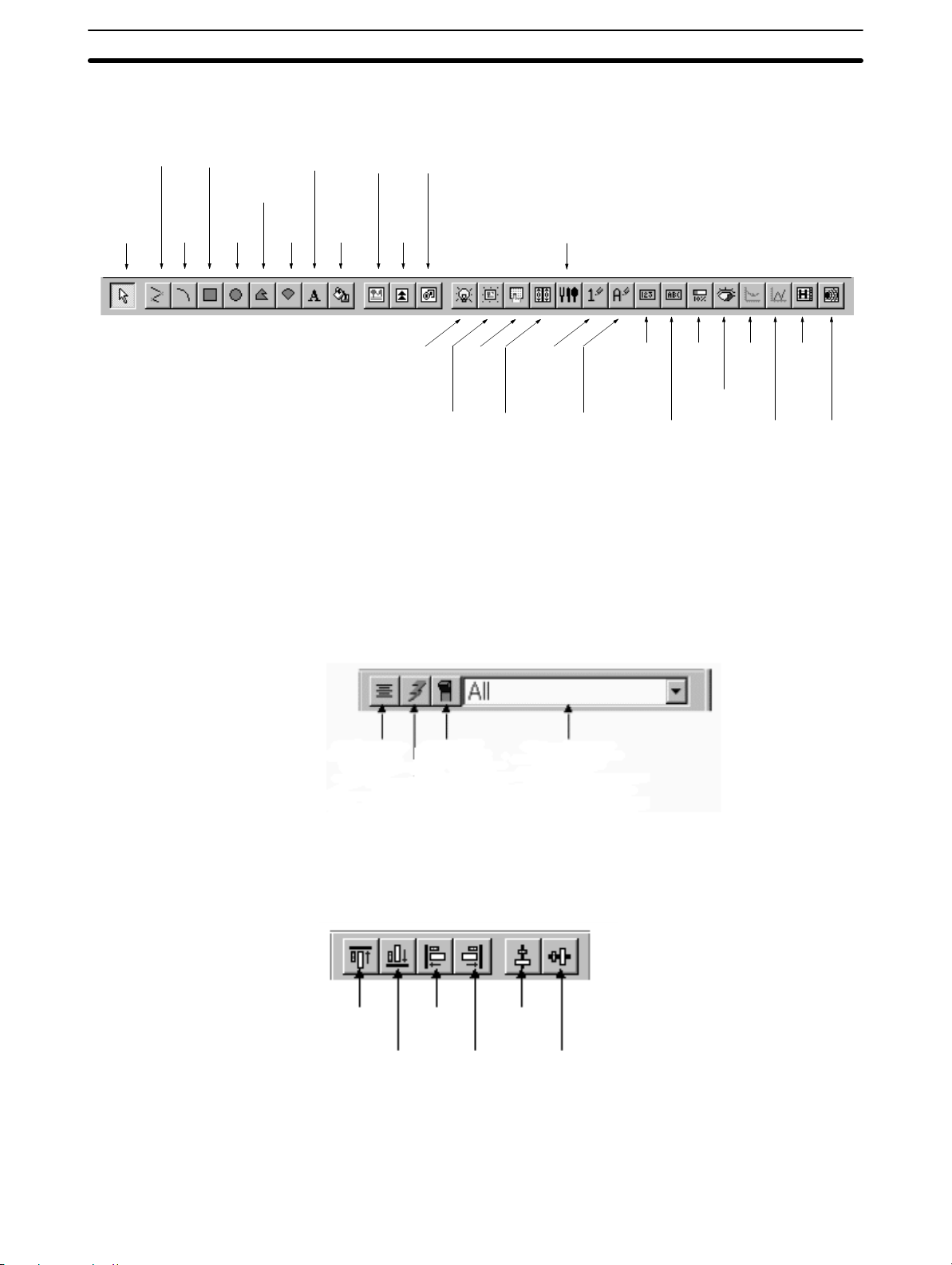
3-2SectionUser Interface
These functions can be called easily without accessing the commands from
the menu bar.
Polyline
Selector
Rectangle
Arc
Circle
Polygon
Sector
Text
Image
object
Tiling
Mark
Standard lamp
Library object
Touch
switch
Recipe
Numeral
input
Numeral
display
Bar
graph
Trend
graph
Alarm
history
Analogue
Image lamp
Thumbwheel
switch
String
input
String
display
Meter
Broker
line
graph
S Utility Bar
Buttons for centralizing label of touch switch or lamp (refer to 5-1-3 Changing
the Display Method on the Support Tool), simulation for flash attribute in fixed
display objects (refer to 5-1-3 Changing the Display Method on the Support
Tool), lamp ON facility (refer to 5-1-3 Changing the Display Method on the Support Tool), and a combo-box for selecting to display certain screen object type
(refer to 5-1-4 Filter Function) are provided.
Alarm
list
Centralize
Label
Simulate
Flash
Simulate
ON/OFF
Filter Screen
Element
S Alignment Bar
This toolbar provides the object alignment to the top, bottom, left, right and also
center in a row and center in a column. (Refer to 6-1-6 Aligning Elements.)
Align
Bottom
Align
Left
Align
Right
Center in
a Column
Center
in
a Row
Align
To p
Reference: Whether or not Status Bar, Standard Toolbar, Draw Bar, Utility Bar and Align-
ment Bar are displayed can be selected, respectively, by the following operation.
42
Page 59
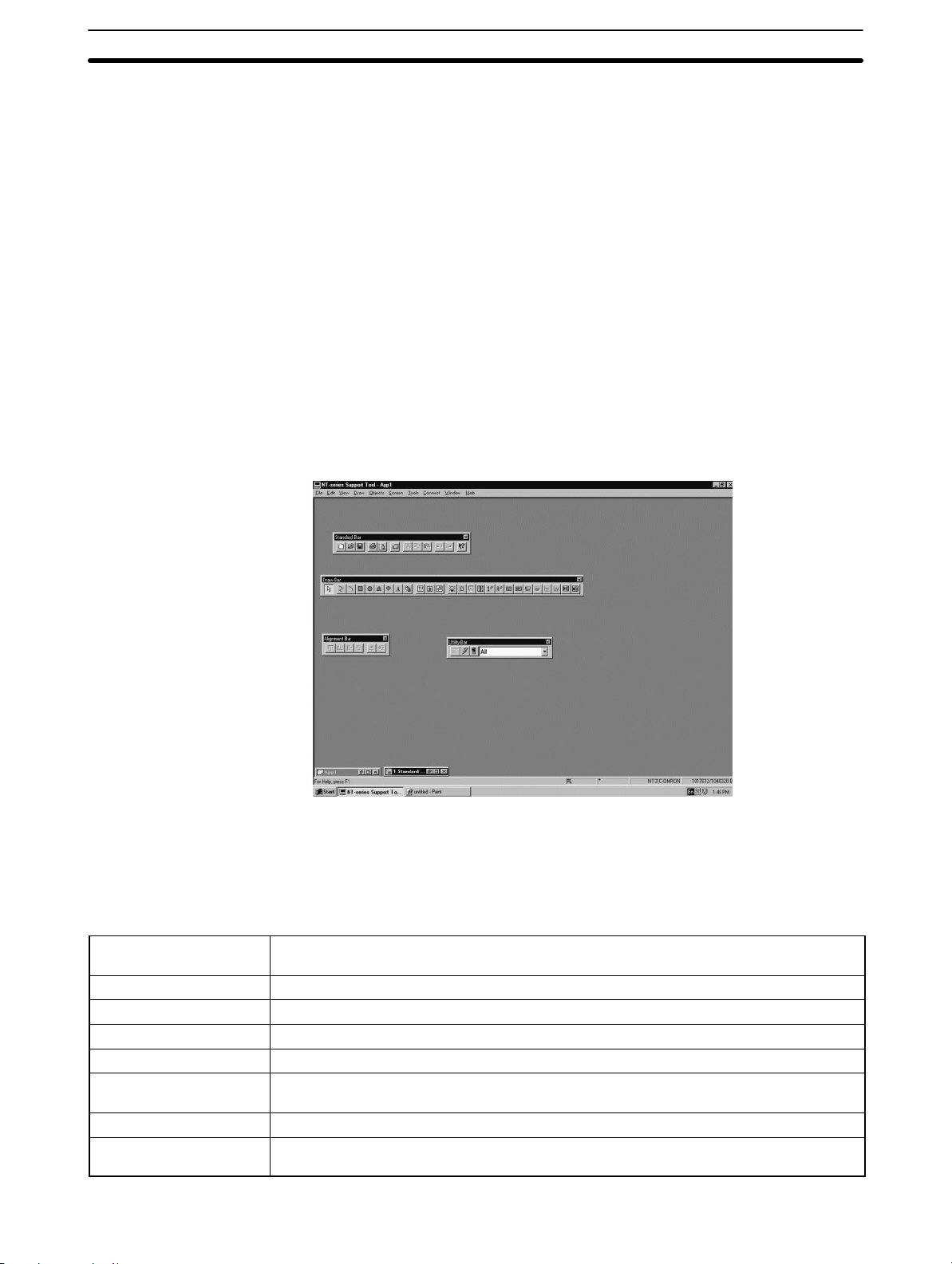
Floating palette
3-2SectionUser Interface
Status Bar: [View] (menu bar) → [Status Bar]
Standard Toolbar: [View] (menu bar) → [Toolbars] → [Standard Bar]
Draw Bar: [View] (menu bar) → [Toolbars] → [Draw Bar]
Utility Bar: [View] (menu bar) → [Toolbars] → [Utility Bar]
Alignment Bar: [View] (menu bar) → [Toolbars] → [Alignment Bar]
Each time you select the item, display/no-display selection changes alternately.
The check mark, if displayed, indicates that the selection of the corresponding
item is to be displayed.
If [Auto hide] invoked by selecting [Start] button (Windows) → [Settings] →
[Taskbar] → [Taskbar Options] is checked, status bar may not be displayed correctly when the window of the Support Tool is maximized. In this case, clear the
checkmark for [Always on top] at [Taskbar Options].
The standard toolbar, draw bar, utility bar and alignment bar can be moved as a
floating palette to a convenient place for your operation.
S Object information on the status bar
The information for the selected object that will be displayed on the status bar is
indicated in the following table. (No information will be displayed when multiple
objects are selected) Information to be displayed may be cut depending on the
resolution of the screen or the selected object.
Screen Element
(Selected item)
Fixed Display Object Fixed Display {Object Name: Attribute}
Fixed Display-Mark Mark Object {Code*1}
Fixed Display-Image Image Object {Reference Type: Code*1: Comment: Size: Compression}
Fixed Display-Library Library Object {Reference Type: Code*1: Comment}
Image Lamp Image Lamp {PLC Address: ON code*1: OFF code*1: ON comment if check else OFF com-
ment}
Standard Lamp Standard Lamp {PLC Address: Label*2}
Touch Switch Touch Switch {Function: PLC Address: Label*2} (If function type is Notify Bit, display Notify
Address, else display Lamp Address)
Information to be displayed
43
Page 60

3-2SectionUser Interface
Screen Element
(Selected item)
Thumbwheel Thumbwheel {PLC Address: Table Entry*3}
Numeral Input Numeral Input {PLC Address: Table Entry*3: Reference Type}
String Input String Input {PLC Address: Table Entry*3: Reference Type}
Recipe Recipe{Recipe Number; Recipe Name; Write Notify Bit; No. of Records: No. of Parameters}
Numeral Display Numeral Display {PLC Address: Table Entry*3: Reference Type}
String Display String Display {PLC Address: Table Entry*3: Reference Type}
Bar Graph Bar Graph {PLC Address: Table Entry*3: Direction}
Trend Graph Trend Graph {Type: Drawing Width: Direction}
Broken-line Graph Broken-line Graph {Direction}
Alarm History Alarm History {Display Image/Library or not}
Alarm List Alarm List {Table Entry*3: Display Image/Library or not}
Analogue Meter Analogue Meter {PLC Address: Table Entry*3}
Information to be displayed
(*1) M: Mark I: Image L: Library
(*2) If the image or library data for when the switch is lit is not specified, the com-
ment for the image or library data for when the switch is not lit will be displayed.
(*3) For the NT21 and the NT31. NT31C, NT631, NT631C with “-V2” or “-V3,” the
information to be displayed depends on the Label Type as follows:
Static: Label
On Off Static: When [View] – [Simulate ON/OFF] setting is ON, displays ON
label, when OFF, displays OFF label.
Numeral Display: Same for Numeral Display information
String Display: Same for String Display information
(*4) N: Numeral Table S: String Table B: Bit Memory Table
3-2-2 Major Functions of Dialog Boxes
A dialog box is a window that is displayed in a fixed size. The purpose of a dialog
box is to set data that is required to execute the functions of the Support Tool.
The following types of dialog boxes are used and the procedure for setting the
data differs according to the type of dialog box.
S Option button
This represents a selection item, with f displayed to the left of the item name.
Only one of the displayed items can be chosen. The item is identified by a black
circle.
S Check box
This represents a selection item, with j displayed to the left of item name.
Items can be selected by giving a check mark in this box.
44
Page 61
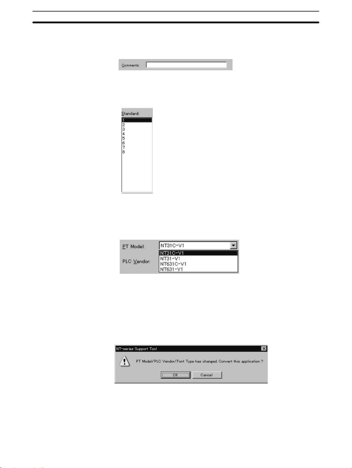
S Text box
This text box is an input field to set characters.
S List box
A list box displays a list of data: the data to be set is selected from the list.
3-3SectionOperation of Screen Data (Application) File
S Combo box
A list of selection items appears in the dropdown list box format. The data to be
set is selected from the list.
3-2-3 Functions of Message Boxes
Message boxes display details of errors that occur during Support Tool operation
and messages that request your confirmation of attempted operations.
When a message box shows up, operation can be continued or cancelled by
pressing the corresponding button in the message box.
3-3 Operation of Screen Data (Application) File
The procedure for operating the screen data file, where the PT screen data is
stored, is described below. The PT Configuration, which determines the basic PT
operation, is also discussed.
45
Page 62
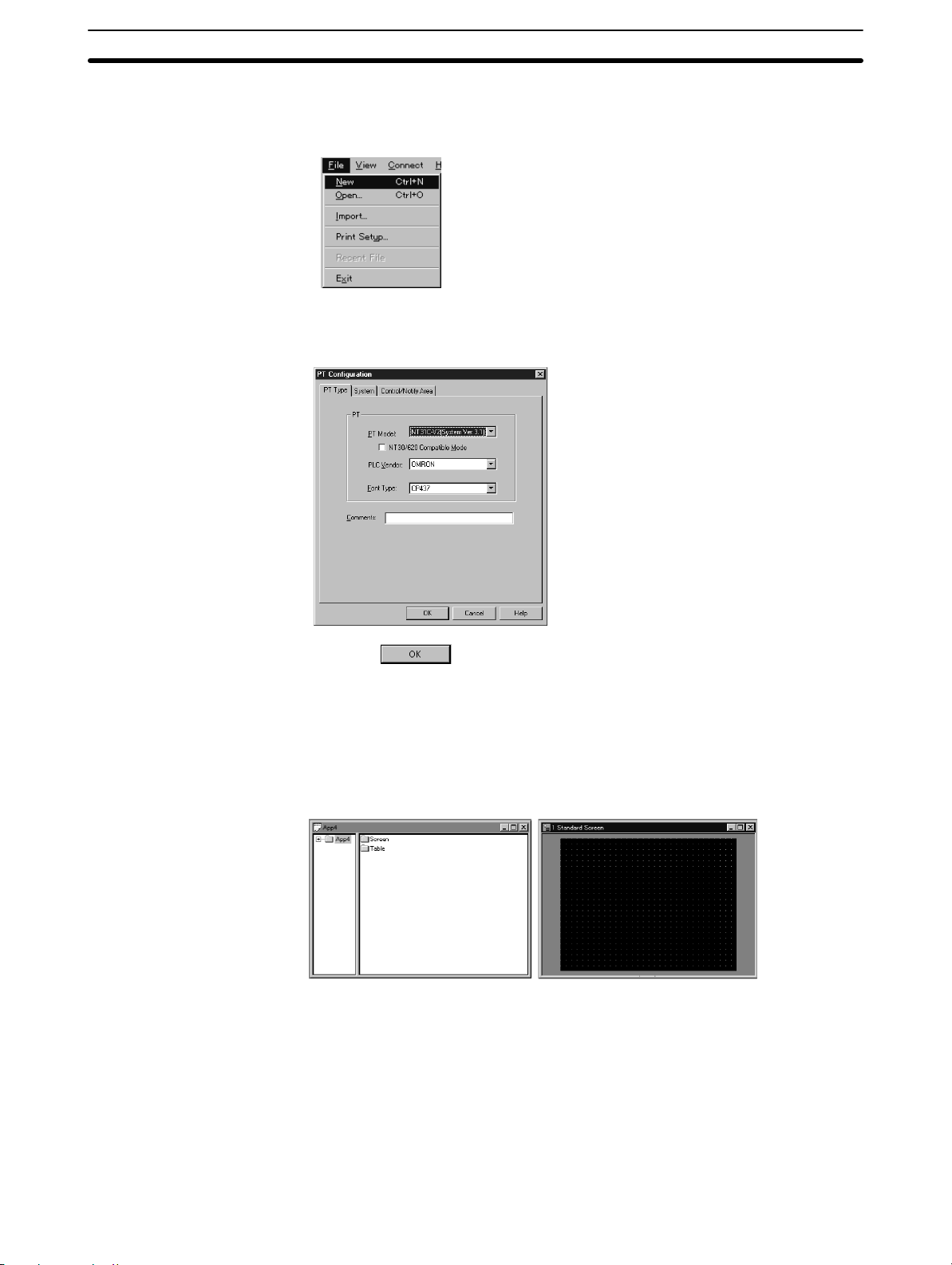
3-3-1 Creating New Screen Data (Application) File
To create new screen data, select [New] in the [File] Menu of the main window.
PT configuration dialog box appears so that users can set information of the application environment and type of PT device.
3-3SectionOperation of Screen Data (Application) File
Click the Button after completing the setting at the PT configuration
dialog box. For details of the setting at the PT configuration dialog box, refer to
Dialog Box Settings in the PT Configuration below.
If the PT is set to the NT21, the clock address dialog box will appear next. Refer
to page 54.
The application manager and the data creation screen (1 Standard Screen) are
displayed.
PT screen data is created by arranging objects on this data creation screen.
The application manager is the tool to manage the screen data created by a user.
For operation procedure, refer to Section 4 Application Manager.
Dialog Box Settings in the PT Configuration
46
Before creating screen data, it is necessary to set the PT configuration and the
Control and Notify Areas that are shared with the PC (PLC).
The operation steps shown below display the PT configuration dialog box.
Page 63
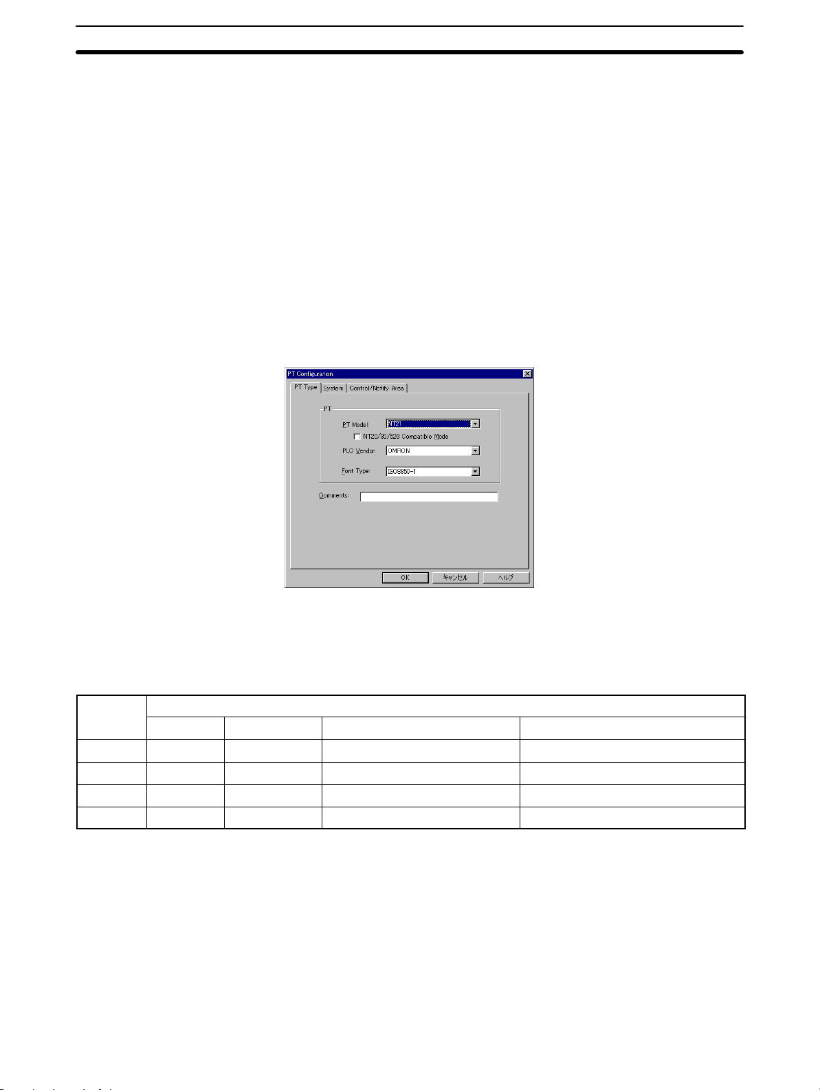
3-3SectionOperation of Screen Data (Application) File
S Menu Bar → [File] → [New] (creating new application)
S Menu Bar → [Tools] → [PT Configuration] (for modifying)
The PT configuration dialog box has a variety of setting items provided in three
pages.
S PT Type page
S System page
S Control/Notify Area page
S PT Type page
The PT Type page is displayed when you click on the [PT Type] tab.
The PT Type page is used to set the hardware configuration of the PT to be
connected.
PT Model
Specify the type of PT to be connected. When you are using the NT31, NT31C,
NT631 or NT631C, refer to the table below to select the correct model according
to the system program being installed.
PT Model
Ver.1.01 Ver.2.0 Ver.2.1 Ver.3.1 or Ver.4.0
NT31 ”NT31” ”NT31-V1” ”NT31-V1(System Ver.2.1)” ”NT31-V2/V3 (System Ver. 3.1)”
NT31C ”NT31C” ”NT31C-V1” ”NT31C-V1(System Ver.2.1)” ”NT31C-V2/V3 (System Ver. 3.1)”
NT631 ”NT631” ”NT631-V1” ”NT631-V1(System Ver.2.1)” ”NT631-V2 (System Ver. 3.1)”
NT631C ”NT631C” ”NT631C-V1” ”NT631C-V1(System Ver.2.1)” ”NT631C-V2/V3 (System Ver. 3.1)”
Reference: To check the system program version installed in a PT, display the following
screens:
S Version display at the upper right position of PT system menu
S PT system menu Expansion mode Version display
With the NT20, either ”NT20S” screen data (compatible with previous NT20S) or
”NT20” screen data (with expanded CS/CJ-series PLC data access) can be
used.
The following PT Models are also available:
System Program
47
Page 64

3-3SectionOperation of Screen Data (Application) File
S NT31-V2
S NT31C-V2
S NT631-V2
S MT631C-V2
NT20/30/620 Compatible Mode
For NT21 and NT31/631-V2 or higher models, the NT20/30/620 Compatible
Mode check box will be enabled. By setting this option, the Control Area will take
4 memory address, instead of 5 and Notify Area will take 3 memory address,
instead of 2. This allows straight conversion for NT30/620 PT models to
NT31/631 or NT20S models to NT21 without the need to modify the PLC program.
PLC Vendor
Specify the usable direct access type from either of the following.
MEMLINK, Mitsubishi_A and Mitsubishi_Fx can be set only with NT31, NT31C,
NT631and NT631C with “-V1” and above.
AB and GE can be set only with NT31, NT31C, NT631 and NT631C below “-V1.”
Siemens can be set only with NT31, NT31C, NT631 and NT631C with “-V1.” (Refer to page 27).
S OMRON
S Mitsubishi_A
S Mitsubishi_Fx
S MEMLINK
S AB
S GE
S Siemens
Font Type
If you are using NT31-V1, NT31C-V1, NT631-V1, NT631C-V1 and above hardware or had NT31, NT31C, NT631and NT631C and been updated the system
program to the -V2 (System Ver.3.1) system program, which is attached to this
Support Tool, it is possible to select the Font Type ISO8859-1 or CP437.
If you are using the European Keyboards, please refer to Appendix K for more
details.
Reference: Specify ”OMRON” as the PLC type when using memory links between the
NT30, NT30C, NT620S, NT620C, and NT625C.
Comment
48
Set the comment that is appended to the screen data file.
An arbitrary character of up to 28 characters can be set.
Reference: The PT model of the screen data that is opened can be changed. If it is
changed, the data is converted automatically. Note that changing of PT models
is allowed only for the restricted combinations shown in Appendix A Data Con-
version.
Page 65
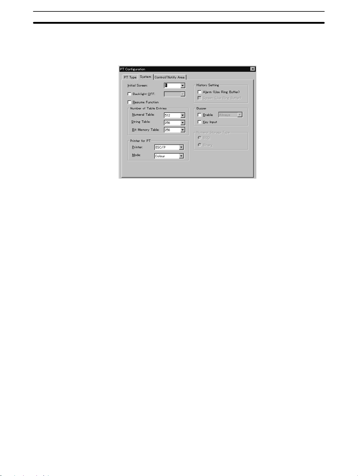
3-3SectionOperation of Screen Data (Application) File
S System page
The System page is displayed when users click on the [System] tab.
Fundamental operating functions can be set in this System page.
Initial Screen
Screen number, which appears when the wrong data is set for PT Control Area
when PT is driven, is selected from the drop-down list box or keyboard input. Normally, this setting is invalid since PT References PT Control Area for the initial
screen number when starting up.
The screen numbers of existing screen data are listed in the list box or only
screen number 1 is displayed if the screen data is newly created.
Backlight OFF
Specify whether or not the backlight OFF function is used.
This option can be selected from System of PT Configuration in the Support Tool.
The Backlight OFF function automatically turns OFF the screen if the Support
Tool is not operated for a certain time period to save the backlight of PT.
If the check box is clicked to utilize the option, the time interval will be displayed in
the drop-down list box to set it.
For details of the PT models that can use this function, refer to Appendix E Sys-
tem Setting (PT Configuration).
Resume Function
The resume function holds the data in the table when the PT is OFF or reset.
For details of the PT models that can use this function, refer to Appendix E Sys-
tem Setting (PT Configuration).
History Setting
This item specifies the method for processing when the Log memory of the alarm
history function and History screen function becomes full.
- Alarm (Use Ring Buffer):
Same meaning with FIFO (First In First Out)
Alarm FIFO system is applied for this function if the log memory area is full.
When new alarm occurs, the oldest record data will be deleted so that the new
data can be stored there.
49
Page 66

3-3SectionOperation of Screen Data (Application) File
If the Alarm function is not chosen, newly coming data is not acceptable to record when the memory space is full.
- Screen (Use Ring Buffer):
Same meaning with FIFO (First In First Out).
When the new screen history occurred, the oldest record data will be deleted
so that new data can be stored there. This is so called FIFO. If this check box is
not ON, newly coming data is not acceptable to record when the memory
space is full.
Either the Alarm and the Screen data is available for the following PT models.
NT30, NT30C, NT21, NT31, NT31C, NT620S, NT620C, NT625C, NT631,
NT631C.
(For NT21, NT31, NT31C, NT631, and NT631C, both Alarm and Screen settings are available.)
Number of Table Entries
Specify the number of numeral memory table entries, character string memory
table entries (String Table), and bit memory table entries.
Setting of the Number of Table Entries is valid for the following PT models.
NT30, NT30C, NT21, NT31, NT31C, NT620S, NT620C, NT625C, NT631,
NT631C
Buzzer –Enable
Specify whether or not the buzzer function is used.
To use the buzzer function, click the check box to enter the check mark. To set the
buzzer function to be unused, click the check box to clear the check mark.
To sound the buzzer only at the occurrence of an alarm, specify [On Error] at the
drop-down list box.
If [Always] is selected for the buzzer function, the buzzer sounds at following
events.
S Occurrence of an error at PT
S Reception of a command from the host
S Screen switching
Setting of the buzzer function is valid for the following PT models.
NT30, NT30C, NT620S, NT620C, NT625C
Reference: With the NT21, NT31, NT31C, NT631, and NT631C, buzzer function settings
are made by system menu operation at the PT and setting from the Support
Tool is not allowed.
50
Buzzer – Key Input
Click the check box of [Key Input] to enter the check mark if you want to sound the
buzzer in response to the input from a touch switch or the extended I/O unit. Clear
the check mark if the key input sound is not to be used.
Printer for PT
A printer can be connected to PT device for printing screen data if required. You
have to specify the type of printer being used by the application for the following
PT models:
Page 67

NT30, NT30C, NT620S, NT620C, NT625C
S Printer
Select one of the Supported printers from the printer drop-down list box.
Although this setting is possible for NT31, NT31C, NT631, NT631C, it is not
valid from Support Tool.
Please set from the Maintenance Mode of PT.
S Mode
Color:
Specify “Color” for color printing.
Designation of Color is valid for the following PT models.
NT30C, NT620C, NT625C
S Tone:
Specify “Tone” for monochrome printing.
If a color type PT is used with Tone set for [Mode], color data is expressed using
a gray scale, printed in monochrome.
3-3SectionOperation of Screen Data (Application) File
These setting are available for the following PT models.
NT30, NT30C, NT620S (Printer only), NT620C, NT625C
For NT21, NT31, NT31C, NT631, and NT631C, this setting has to be selected
from PT.
Numeral Storage Type
BCD or Binary can be selected for the storage type of the Numeral memory table.
This setting is available only when the time the Storage Type in the Numeral
memory table has [System] setting. When BCD or Binary is set for Numeral
memory table Storage Type, this setting in the PT Configuration will be ignored
and follows the storage type in the Numeral Table.
This setting is available for the following PT Model.
NT21, NT31, NT31C, NT631, NT631C
S Control/Notify Area page
The Control/Notify Area page is displayed when you click on the [Control/Notify
Area] tab.
The Control/Notify Area page is prepared to set the PT Control area, controlling PT from PC (PLC) and for PT Notify Area, notifying PT information to a PC
51
Page 68

(PLC and for window control area, controlling a window (NT21, NT31, NT31C,
NT631, NT631C with “-V1” and “-V2” only).
PT Control Area
PC (PLC) Address
Set the type of words at the PC (PLC) and the first address (word number) of
the area used as the PT Status Control Area.
3-3SectionOperation of Screen Data (Application) File
The PT Status Control Area differs depending on the PT model and it occupies
the following number of words.
NT31, NT31C, NT631, NT631C:
For V1 models, and V2 models without
NT20/30/620 Compatible mode: 5 words
For V2 models with NT30/620 Compatible mode: 4 words
NT21:
Without NT20/30/620 Compatible mode: 5 words
With NT20/30/620 Compatible mode: 4 words
Other models: 4 words
Comments
Set a comment concerning this area.
As a comment, up to 16 character can be set.
PT Notify Area
PC (PLC) Address
Set the type of words at the PC (PLC) and the first address (word number) of
the area used as the PT Status Notify Area.
The PT Status Notify Area differs depending on the PT model and it occupies
the following number of words.
NT31, NT31C, NT631, NT631C:
For V1 models and V2 models without NT20/30/620 Compatible mode: 2
words
For V2 models with NT20/30/620 Compatible mode: 3 words
52
NT21:
Without NT20/30/620 Compatible mode: 2 words
With NT20/30/620 Compatible mode: 3 words
Other models: 3 words
Page 69

3-3SectionOperation of Screen Data (Application) File
Comments
Set a comment concerning the area set as the PT Status Notify Area.
As a comment, a character string of up to 16 characters can be set.
Window Control Area
PC (PLC) Address
Set the type of words at the PC (PLC) and the first address (word number) of
the area used as the Window Control Area.
Window Control Area differs depending on the PT model and it occupies the
following number of words.
NT21 and NT31, NT31C, NT631, NT631C with “-V1” or “V2”: 9 words
Other models: can not be used
Comments
Set a comment concerning the area set as the Window Control Area.
As a comment, a character string of up to 16 characters can be set.
Note Set memory addresses so that the PT Control Area, PT Notify Area and Window
Control Area do not overlap.
S PC (PLC) Address dialog box
Clicking on the [Set] button in the [PT Control Area], [PT Notify Area] or [Window Control Area] displays the PC (PLC) Address dialog box.
In the PC (PLC) Address dialog box, the PC (PLC) address of the PT Status
Control Area, the PT Status Notify Area and the Window Control Area can be
set by specifying the area type and address individually. The setting made in
the PC (PLC) Address dialog box will be reflected on the setting made in the
[PC (PLC) Control Area], [PT Notify Area] or [Window Control Area].
Use the PC (PLC) Address dialog box only when the area type and address are
input individually. If the PC (PLC) address is directly input in the Control/Notify
Area page, it is not necessary to call this dialog box.
Example PLC Vendor: OMRON
Channel (Word)
Specify the type of PC (PLC) area that is used as a PT Status Control Area, a
PT Status Notify Area or a Window Control Area by selecting an item from the
drop-down list box.
Address
Specify the first word address in the PC (PLC) area that is to be used as the PT
Status Control Area, PT Status Notify Area, and Window Control Area.
53
Page 70

Clock Address
3-3SectionOperation of Screen Data (Application) File
I/O Comments
Set a comment concerning the area set as the PT Status Control Area, a PT
Status Notify Area, or a Window Control Area.
As a comment, a character string of up to 16 characters can be set.
When the PT is set to the NT21, the addresses must be set to read the clock
from the PLC host. This setting is not necessary for other models of PT.
If the PT is set to the NT21 on the tools page of the PT configuration dialog box,
the clock address dialog box shown below appears. Always set an address
when using the clock function (data displays, screen display history, or alarm
history).
PLC Address
Set the area and the address of the first word from which to read the clock data.
A Clock Data Area will be defined consisting of 4 words starting at the specified
address.
I/O Comments
Set a comment for the address used to define the Clock Data Area. Up to 16
character can be input.
S PLC Address Dialog Box
This dialog box is set in the same way as the one for the PT configuration dialog
box.
3-3-2 Reading the Existing Screen Data (Application) File
To read the screen data that is saved in a file, select [File] → [Open] from the main
window menu.
54
Page 71

3-3SectionOperation of Screen Data (Application) File
The dialog box for the applicable folder, file name, and files of type exist appears
to specify them.
NTST Application (*.onw)
After specifying the folder, file name, and file type click on the [Open] button.
The application manager of the read out screen data is displayed.
With NT-series Support Tool for Windows, following screen data files can be han-
dled.
onw
mmi
For details, refer to File Types in page 56
Reference: S Recent used files will be shown at the bottom of [File] menu. Recent four files
can be opened from this command.
S NT-series Support Tool for Windows (Ver. 4.7) can read the screen data that is
created using an earlier version of NT-series Support Tool.
S It is not possible to read screen data created by NT-series Support Tool for Win-
dows (Ver. 4.7) with an earlier version of NT-series Support Tool.
S With MMI files, the screen data created by the Support Tool Ver.4 can be read
using Support Tool Ver.3.j as long as the PT model is supported with Ver.3.j.
(With MMI format, user group and grid information will be lost.)
e.g.
NT30C MMI file created with Ver.4.j
Can be read with Ver.3
NT31C-V2 MMI file created with Ver.4.j
Cannot be read with Ver.3
3-3-3 Saving the Screen Data (Application) File
After creating the screen data, save it to a file.
The procedure for saving the screen data to a file is: [File] (main window menu)
→ [Save], or [File] (main window menu) → [Save As].
Save:
The existing screen data of the opened file is overwritten by the new screen
data.
55
Page 72

If the file was opened using [New], the operation to be followed is the same as
for saving a file by selecting [Save As].
Save As:
The created or edited screen data is saved by specifying the folder and the file
name.
S File name setting dialog
If you select [Save] when creating new screen data or [Save As], the file name
setting window (Save As) opens.
3-3SectionOperation of Screen Data (Application) File
NTST Application (*.onw)
After inputting the folder and file name, click the Button the screen
data is saved to the specified file.
If the file name of an existing file is specified, a message requesting confirmation that the file is to be overwritten is displayed.
S File types
When saving files in file name setting dialog, either of following two file types
can be selected.
S NTST screen data (*.onw) format (onw format)
This is a standard file format for Support Tool.
Use this format to save screen data normally.
S Memory map image file (*.mmi) format (mmi format)
This is a file format to which screen data is compressed after deleting information used only for Support Tool. (Data to be lost are grid setting and grouping
information.)
Use this format for purposes such as transferring screen data using FD.
It is advisable to save the same data with onw format also, since part of information are lost with this format as mentioned above.
56
Once you saved data, specified file types will not be changed until you exit the
Support Tool or perform saving/reading the onw file. (Data will be saved in the
format same as before when you select “Save” to save it.) If you want to change
the file type, select “Save As.”
Reference: S It is not possible to save data in DOS format.
S Once you read the data that was created using DOS version Support Tool by
NT-series Support Tool for Windows, do not upload the data with DOS tool
Page 73

even if it has been download to PT. Downloading will be possible; however, the
data may not be used with DOS version Support Tool correctly.
ST
DOS version Support Tool
Upper
compatibility
Windows version Support Tool
S With mmi file format, error check is executed before saving. By this error check,
data that cannot be downloaded to PT will not be stored.
S With the Support Tool on CD-ROM, the NT Transfer Utility, which transmits
mmi file to the PT, is supplied. For details, refer to Appendix C NT Transfer Util-
ity.
3-3-4 Closing the Screen Data (Application) File
It is not possible to open two or more screen data files with one Support Tool. So
when you want to edit different screen data file, you need to close the currently
opened file, or start up the second Support Tool using the [Import Component]
command from the [File] menu. For details of Import Component, refer to 3-3-6
Importing Components from Different Screen Data File (Starting Up the Second
Support Tool).
PT
3-3SectionOperation of Screen Data (Application) File
NT20, NT20S, NT30,
NT30C, NT620S,
NT620C/NT625C
To close application, select [Close] from [File] in the main window menu.
If the screen data (application) has not been saved, a message requesting confirmation of saving it is indicated/displayed.
If the file name is not set, the name setting dialog appears. If
the file name has been already determined, the data will be
overwritten.
The screen data file closes without saving the screen data.
The file close operation is canceled.
3-3-5 Importing (Reading) the DOS Version Screen Data (Application)
File
The Support Tool has a function for reading screen data files created using the
previous DOS version Support Tool. Note that although the DOS version screen
data files can be read, files cannot be saved in DOS format.
57
Page 74

3-3SectionOperation of Screen Data (Application) File
The procedure for reading a DOS version screen data file is:
[File] (main window menu) → [Import].
For “Files of type,” select any of the following items according to the model of
Support Tool used to create the screen data you are going to read.
S M1S: Screen data for NT11S/NT11
S M2S: Screen data for NT20S
S M6S: Screen data for NT600S
S G6S: Screen data for NT30, NT30C, NT620S, NT620C, and
NT625C
Click the
name.
The application manager of the read screen data will be displayed.
Reference: S For details of the PT models and types, the Support Tool can create screen
data for, refer to 1-6 Usable Hardware Combinations.
S Refer to Appendix A Data Conversion to reuse or convert screen data from
previous PT models.
Button after selecting the folder and specifying the file
3-3-6 Importing Components from Different Screen Data File (Starting
Up the Second Support Tool)
Select [Import Component] from the [File] menu and you can start up the second
Support Tool and open a different screen data file. By reading out the different
screen data files with the two Support Tools, data copying/pasting can be performed easily between the files.
58
Page 75
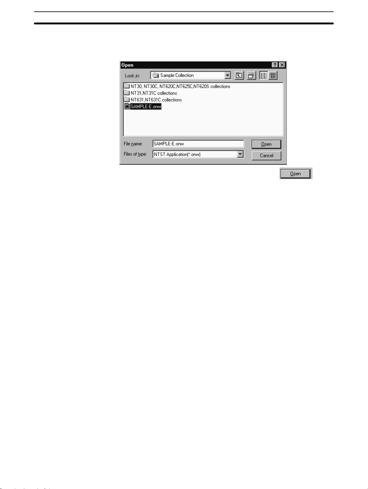
3-3SectionOperation of Screen Data (Application) File
When you select [Import Component], a dialog box to specify the file to be read is
displayed. (For details of this dialog, refer to 3-3-2 Reading the Existing Screen
Data (Application) File.)
After specifying the folder, file name and file type, click the Button.
The second Support Tool starts up and the application manager of the read out
screen data is displayed.
Reference: S It is not possible to start up the second Support Tool from the [Start] button of
Windows (Error message will be displayed). Be sure to select [Import Component] from the [File] menu in the main window of the first Support Tool.
S Copy/paste operation can not be performed between the two files if the PT
model of the two files is different. In this case, perform data conversion beforehand so that the PT model setting of the copy source screen data matches to
the setting of the copy destination screen data. (Selected PT model can be
checked on the status bar.)
S It is not possible to edit the same screen data file by two Support Tools. If you try
to read out the file that is already opened by the other Support Tool, error message will be displayed.
S The second Support Tool can read out the screen data file regardless of the file
types (onw, mmi).
S When the second Support Tool is started, the windows of both Support Tools
are automatically resized into normal windows that overlap each other to facilitate the copy operation between the files.
S It is not possible to open one more Support Tool when two Support Tools are
already started.
S [Import Component] will not be displayed in the [File] menu when no screen
data is opened with the Support Tool.
S Conversion of PLC address is executed when the PLC vendor (direct access)
is different between the copy source/destination screen data.
S Conversion of key code is executed when the key code (font type) is different
between the copy source/destination screen data.
S In case of the numeral/string table and bit memory table, if the table size of
copy destination is smaller than the size of copy source, excessive entries will
be discarded.
S To achieve higher performance, close the second Support Tool after you com-
pleted import operation.
59
Page 76

S It may take time to read out MMI file since data checking is performed before
opening the file.
Possible Operation between Two Support Tools
While screen data files of the same PT model are opened with the two Support
Tools, following operations are possible.
a. Copying, cutting, pasting and drag & drop of a screen between application
managers (multiple screens can be also handled). (Refer to 4-2-4 Copying a
Screen.)
b. Copying, cutting, pasting and drag & drop of a table data between application
managers (All the data in a table is handled, it is possible to handle a table
entry individually or to handle multiple table entries collectively.) (Refer to
4-2-9 Copying the Whole Table.)
3-3SectionOperation of Screen Data (Application) File
60
c. Copying, cutting, pasting of a number/code between the following table
entries (Drag & drop is not possible).
Between image table entries (Refer to NO TAG Operating the Image Table.)
Between library table entries (Refer to NO TAG Operating the Library Table.)
Between bit memory table entries (Refer to 7-1-4 Edit Operation.)
Between numeral table entries (Refer to 7-1-4 Edit Operation.)
Between string table entries (Refer to 7-1-4 Edit Operation.)
Between extended I/O output table entries (Refer to 7-1-4 Edit Operation.)
Between extended I/O input table entries (Refer to 7-1-4 Edit Operation.)
d. Copying, cutting, pasting and drag & drop of objects between editing screens
or library editors. (Drag & drop can not be performed if the copy destination
Page 77

3-3SectionOperation of Screen Data (Application) File
window is hidden under other windows.) (Refer to 6-1-5 Copying, Cutting,
Pasting, and Deleting Elements.)
e. Copying, cutting, pasting of the specified area between image editors or mark
editors (Drag & drop is not possible). (Refer to NO TAG Creating Image Data
Using Image Editor, NO TAG Creating Marks Using the Mark Editor.)
These operating procedures are same as normal operations of copy, cut, paste
and drag & drop on one Support Tool.
Copying/Pasting an Object That Contains Image/Library Data
Even if a screen or an object that contains image/library data is pasted onto a
different screen data file, image/library data itself is not copied if NT-series Support Tool version number is lower than 4.6.
If you want to copy/paste an object that contains image/library data between
screen data files, you need to copy the image/library data referenced by the object beforehand.
Ex: Copying/pasting a fixed-display image that references image code 0001
while the contents of the code are different between the screen data files
As shown above, image data to be displayed will vary even if both objects are
referencing the same code, when the contents of the referenced image code are
different between the screen data files. (When no data is registered to the refer-
enced code,
is displayed. )
3-3-7 Using Method of Parts Collection
With the Support Tool on CD-ROM, Parts Collection is supplied.
In this section, using method of Parts Collection is described.
61
Page 78

Parts Collection
Reference: S Parts Collection is supplied only for the Support Tool on CD-ROM. It can be
Operation Procedure
3-3SectionOperation of Screen Data (Application) File
Lamps and touch switches will be graphical and expressive parts when they are
combined with image/library data or image lamps. These graphical lamps and
touch switches are registered to the Parts Collection (Parts Collection for each
PT model is provided).
Using [Import Component] command, desired data can be copied/pasted from
Parts Collection to the editing screen easily.
installed by specifying “Sample Collection” when installing the Support Tool.
S Parts Collection for NT11S/NT11, NT20/NT20S and NT600S is not supplied.
S Parts Collection is created in MMI format. It may take time to read out/save
MMI file.
S If you install the Parts Collection, the Parts Collection List, which shows how to
use the Parts Collection, the list of screen images, will be automatically
installed as well. This list is stored in the Parts Collection List folder inside the
Sample collection folder.
To use the Parts Collection, follow the procedure below.
Here, operations such as copying, pasting, drag & drop are not described in details. Please refer to NO TAG Image Editor, NO TAG Library Editor and 6-1-5 Co-
pying, Cutting, Pasting, and Deleting Elements.
(1) Open the screen data file to which you want to paste data from Parts Collec-
tion.
(2) Select [Import Component] from the [File] menu.
(3) Dialog box to specify the file to be opened is displayed. Open the Sample
Collection folder in the folder that Support Tool has been installed into. Then,
open the folder of the required PT model (see below). Select “Memory Map
Image File (*.mmi)” as a file type.
Parts Collection for each PT model is displayed. Specify the Parts Collection
of the PT model same as the currently opened screen data file and click the
Button.
Second Support Tool starts up and the selected Parts Collection opens.
62
(4) In the screen data file of Parts Collection, decide the object that you want to
import.
(5) If the object contains image/library data, the image/library data should be co-
pied between image/library table entries beforehand by copy/paste operation
if NT-series Support Tool version number is lower than 4.6. Follow the proce-
Page 79

3-3SectionOperation of Screen Data (Application) File
dure below.
Code number to be copied can be checked in the property of an object. (Ref-
erenced image/library code is also displayed on the status bar for some ob-
ject when they are selected.)
If image/library copying is not performed beforehand, display will not be as
intended since the image/library allocated to the code is not copied even if the
object itself is copied.
Procedure
a. Open the property of an image lamp or image/library data to be imported and
check the referenced image/library code.
b. Select [Image Editor] or [Library Editor] from the [Tools] menu and copy ([Edit]
– [Copy]) the code to be imported on the image/library table.
c. Open the image/library table of the screen data file of copy destination and
paste the image/library data that has been copied.
This time, if the copy destination code number is different from the copy
source code number, display will not be correct when the object is pasted.
Register the same code number as copy source by clicking the
ton.
But-
(6) Drag & drop the object that you want to import from the screen data file of
Parts Collection to the screen data file of copy destination ([Copy], [Paste] in
the [Edit] menu can be used also).
63
Page 80

Page 81

SECTION 4
Application Manager
This section shows how the application manager is used when checking the created data, copying screen data, setting a
memory table, operating a window.
4-1 What Is the Application Manager? 66. . . . . . . . . . . . . . . . . . . . . . . . . . . . . . . . . . . . . . . . . . . .
4-2 Operating the Application Manager 67. . . . . . . . . . . . . . . . . . . . . . . . . . . . . . . . . . . . . . . . . . .
4-2-1 Opening a Data Creation Screen 67. . . . . . . . . . . . . . . . . . . . . . . . . . . . . . . . . . . . . .
4-2-2 Closing a Creation Screen 67. . . . . . . . . . . . . . . . . . . . . . . . . . . . . . . . . . . . . . . . . . .
4-2-3 Creating a New Screen 67. . . . . . . . . . . . . . . . . . . . . . . . . . . . . . . . . . . . . . . . . . . . .
4-2-4 Copying a Screen 68. . . . . . . . . . . . . . . . . . . . . . . . . . . . . . . . . . . . . . . . . . . . . . . . . .
4-2-5 Deleting a Screen 69. . . . . . . . . . . . . . . . . . . . . . . . . . . . . . . . . . . . . . . . . . . . . . . . . .
4-2-6 Displaying and Setting the PT configuration 69. . . . . . . . . . . . . . . . . . . . . . . . . . . . .
4-2-7 Displaying and Setting Screen Properties 69. . . . . . . . . . . . . . . . . . . . . . . . . . . . . . .
4-2-8 Editing a Table 69. . . . . . . . . . . . . . . . . . . . . . . . . . . . . . . . . . . . . . . . . . . . . . . . . . . .
4-2-9 Copying an Entire Table 70. . . . . . . . . . . . . . . . . . . . . . . . . . . . . . . . . . . . . . . . . . . .
4-2-10 Saving the Screen Data (Application) to a File 71. . . . . . . . . . . . . . . . . . . . . . . . . . .
4-2-11 Error Check (Validation) 71. . . . . . . . . . . . . . . . . . . . . . . . . . . . . . . . . . . . . . . . . . . .
4-2-12 Sending (Downloading) the Data to a PT 73. . . . . . . . . . . . . . . . . . . . . . . . . . . . . . .
4-2-13 Window Menu 74. . . . . . . . . . . . . . . . . . . . . . . . . . . . . . . . . . . . . . . . . . . . . . . . . . . .
4-2-14 Help Menu 76. . . . . . . . . . . . . . . . . . . . . . . . . . . . . . . . . . . . . . . . . . . . . . . . . . . . . . .
65
Page 82

4-1 What Is the Application Manager?
A screen data (application) file holds a variety of data. The application manager
is a data management tool used for managing the various types of screen data.
Since the application manager displays the data in tree style, you can check the
created data or read the necessary data easily.
(The number and type of screens and tables displayed in the application manager vary according to the setting made for [PT Model] of [PT Type] in the PT configuration. Bit map shown above is in case of NT31, NT31C, NT631 and NT631C.)
4-1SectionWhat Is the Application Manager?
The application manager provides following operations:
Opening a data creation screen
Creation of new application
Copying a screen
Deleting a screen
Displaying and setting PT configuration
Displaying and setting screen properties
Editing tables
Saving the created data to a file
Sending (downloading) the created data to a PT
Icons used by the application manager
App 1: Name of application folder
When a file name has been specified, the file name specified by App 1 is used.
Double clicking of this icon opens a set of sub-data box by screen type.
screen: Screen data box
Double clicking of this icon displays the screen data boxes classified by group.
66
table: Table data box
Double clicking of this icon shows memory tables classified by icon.
1-1899.2000 (Standard): Screen data boxes classified by screen type
1-1899.2000: Indicates a screen number.
Standard: Indicates screen type.
Double-clicking of this icon displays the screen icons in a group.
The screen number and screen type displayed here differ from PT models.
Page 83

: Screen icon
1: Indicates a screen number.
Double clicking of this icon opens a data creation screen.
numeral memory table: Table data icon
Numeral memory table: Indicates a table type.
Double clicking of this icon opens a memory table dialog box setting.
The type of table to be displayed differs depending on the PT model.
4-2SectionOperating the Application Manager
When you click on [)], displayed to the left of a
clicked icon are displayed. Clicking on [−] hides these icons.
4-2 Operating the Application Manager
The procedure for operating and setting the data using the application manager
is shown below.
Two types of operations - mouse operation and menu operation - are possible.
For the menu driven operation, short-cut keys (keys used to call menu functions)
may be used instead of displaying the menu.
4-2-1 Opening a Data Creation Screen
The procedure for opening a creation screen of existing data is shown below.
Operation using the mouse (1)
(1) Double click the screen icon.
Operation using the mouse (2)
(1) Click the right mouse button at the screen icon.
(2) Select [Open].
4-2-2 Closing a Creation Screen
icon, icons existing under the
The procedure for closing a creation screen is shown below.
Operation using the mouse
(1) Click the
4-2-3 Creating a New Screen
The procedure for opening a new screen is shown below.
Operation using the mouse
(1) Click the screen data box icon, or right click the mouse on the screen data
box (classified by group).
(2) Select [New], choose the screen type, then click the
(3) Input a screen number and a comment, then click the
Operation using the menu
(1) Select [New] from [Screen] in the menu bar.
(2) Select the screen type, then click the
Button at the upper right corner in the data creation screen.
Button.
Button.
Button.
67
Page 84

(3) Input a screen number and a comment, then click the Button.
4-2-4 Copying a Screen
The procedure for copying an existing screen to another screen number is shown
below.
Reference: The operations shown below can be performed between different screen data
files of the same PT model by starting up two Support Tools. For details, refer to
3-3-6 Importing Components from Different Screen Data File (Starting Up the
Second Support Tool).
Operation using the mouse (1)
(1) Specify the screen icon.
(2) Click right button of the mouse on the selected screen icon, then select
(3) Click right button of the mouse on one of the screen icon, then select [Paste].
4-2SectionOperating the Application Manager
Multiple screen icons can be selected by dragging the mouse cursor while
pressing the Shift key or Ctrl key.
[Copy].
Operation using the mouse (2)
Operation using the menu
(4) Input a screen number, then click the
The screen number of the copy source screen is displayed as a duplicated
number, and in the new screen number field, the smallest number of the
available screen numbers is displayed.
If you input an existing screen number, a confirmation message is displayed
to overwrite it.
(1) Specify the screen icon.
Multiple screen icons can be selected by dragging the mouse cursor while
pressing the Shift key or Ctrl key.
(2) Drag the selected screen icon in the screen icon display area.
(3) Input a screen number, then click the
The screen number of the copy source screen is displayed as a duplicated
number, and in the new screen number field, the smallest number of the
available screen numbers is displayed.
If you input an existing screen number, a confirmation message is displayed
to overwrite it.
(1) Specify the screen icon.
Button.
Button.
68
Multiple screen icons can be selected by dragging the mouse cursor while
pressing the Shift key or Ctrl key.
(2) Select [Copy] from [Edit] in the menu bar.
(3) Then select [Paste] from [Edit] in the menu bar.
(4) Input a screen number, then click the
The screen number of the copy source screen is displayed as a duplicated
number, and in the new screen number field, the smallest number of the
available screen numbers is displayed.
If you input an existing screen number, a confirmation message is displayed
to overwrite it.
Button.
Page 85

4-2-5 Deleting a Screen
The procedure for deleting a created screen is shown below.
Operation using the mouse
(1) Specify the screen icon.
Multiple screen icons can be selected by dragging the mouse cursor while
pressing the Shift key or Ctrl key.
(2) Click right button of the mouse on the selected screen icon, then choose
[Delete].
The message requesting your confirmation is displayed.
Operation using the menu
(1) Specify the screen icon.
Multiple screen icons can be selected by dragging the mouse cursor while
pressing the Shift key or Ctrl key.
(2) Select [Delete] from [Edit] in the menu bar.
A message requesting your confirmation is displayed.
4-2-6 Displaying and Setting the PT configuration
4-2SectionOperating the Application Manager
The procedure for displaying the PT configuration dialog box is shown below.
For details, refer to Dialog Box Setting in the PT Configuration on page 46.
Operation using the mouse
(1) Click right button of the mouse on the screen data (application) file icon, then
select [Setup].
Operation using the menu
(1) Select [PT Configuration] from [Tools] in the menu bar.
4-2-7 Displaying and Setting Screen Properties
The procedure for displaying the property setting dialog box is shown below.
For details, refer to 5-1 Types of Screens, Common Dialog Box Settings and Op-
erations.
Operation using the mouse
(1) Click right button of the mouse on the screen data file icon, then select
[Properties].
Operation using the menu
(1) Select the screen icon.
(2) Select [Properties] from [Screen] in the menu bar.
Reference: The following operations can also display the screen property setting dialog
4-2-8 Editing a Table
box.
Click right button of the mouse on the editing screen where no objects are reg-
istered, then select [Properties].
Double click on the editing screen where no objects are registered.
The procedure for displaying the table setting dialog box is shown below.
69
Page 86

For details, refer to Section 7 Memory Table Setting or Section 8 Editing Graphic
Data.
Operation using the mouse (1)
Double click the icon of the table data to be edited.
Operation using the mouse (2)
Make a right click on the icon of the table data to be edited, then select [Modify].
Operation using the menu
(1) Select [Tools] in the menu bar, then choose [Table], [Image Editor], [Library
Editor] or [Mark Editor].
(2) If [Table] is chosen, select the tab of the table to be edited.
4-2-9 Copying an Entire Table
An entire table can be copied between the screen data files of the same PT model by starting up two Support Tools.
Caution: Copying of tables, screens, and objects between two screen data files involves
addition or overwriting of PLC address. Please check the movement sufficiently
before shifting to actual operation.
4-2SectionOperating the Application Manager
Reference: To start up second Support Tool, select [Import Component] from [File] menu,
Operation using the mouse (1)
For details, refer to 3-3-6 Importing Components from Different Screen Data
File (Starting Up the Second Support Tool).
If the whole table is copied, all the contents in the specified table are copied
collectively. For method to copy the individual data in a table, refer to Section 7
Memory Table Setting or Section 8 Editing Graphic Data.
A check box for “Overwrite PLC Address” appears when copying the whole
table indicated below. If this check box is checked, PLC address setting is overwritten. If not checked, settings such as initial value will be overwritten but the
PLC address setting remains the same. Note that I/O comments are not copied
even if the PLC address is overwritten. If you need the same I/O comment,
copy the I/O comment.
Bit memory table, Extended I/O output table, Numeral table, String table, FKey input notify table
(1) Specify the table data icon.
Multiple tables can be selected by dragging the mouse cursor while pressing
the Shift key or Ctrl key.
(2) Click right button of the mouse on the selected table data icon, then select
[Copy].
(3) Click right button of the mouse on the desired table in the table data icon dis-
play area of another Support Tool, then select [Paste].
Operation using the mouse (2)
70
(4) In the confirmation dialog box, click the
“Overwrite PLC Address” appeared in the dialog box, make the setting as
required.
(1) Specify the table data icon.
Multiple tables can be selected by dragging the mouse cursor while pressing
the Shift key or Ctrl key.
Button. If a check box for
Page 87

4-2SectionOperating the Application Manager
(2) Drag the selected table data icon to the table data icon display area of anoth-
er Support Tool.
(3) In the confirmation dialog box, click the
“Overwrite PLC Address” appeared in the dialog box, make the setting as
required.
Operation using the menu
(1) Specify the table data icon.
Multiple tables can be selected by dragging the mouse cursor while pressing
the Shift key or Ctrl key.
(2) Select [Copy] from [Edit] in the menu bar.
(3) Then select [Paste] from [Edit] in the menu bar of another Support Tool.
(4) In the confirmation dialog box, click the
“Overwrite PLC Address” appeared in the dialog box, make the setting as
required.
4-2-10 Saving the Screen Data (Application) to a File
The procedure for saving the screen data to a file is shown below.
For details, refer to 3-3-3 Saving the Screen Data (Application) File.
Please save frequently. Support Tool will not save automatically.
Operation using the mouse
Button. If a check box for
Button. If a check box for
(1) Click right button of the mouse on the screen data file icon, then select
[Save] or [Save As].
If you select [Save] for a file other than a new file, the saving operation starts
immediately without prompting dialog box.
(2) Specify the folder and file name of the destination and click the
ton.
If you specify an existing file, a message requesting your confirmation is dis-
played if it is overwritten.
Operation using the menu
(1) Select [File] in the menu bar, then choose [Save] or [Save As].
If you select [Save] for a file other than a new file, the saving operation starts
immediately without prompting dialog box.
(2) Specify the folder and file name of the destination and click the
ton.
If you specify an existing file, a message requesting your confirmation is dis-
played if overwriting should be done.
4-2-11 Error Check (Validation)
The Support Tool has a function to check the data such as limitations of screen
elements and PC (PLC) address assignments in order to prevent illegal data
from being downloaded. This is called Validation.
But-
But-
The following three validation functions are provided:
Validation performed on real time
71
Page 88

The Support Tool provides real time validation while users are creating data.
This function mainly checks the elements one by one. Moreover, maximum
number of elements and memory size will be also watched.
Validation performed from the [Tools] menu → [Validate]
It is also possible to perform the Validation using [Tools] → [Validate] from the
menu bar.
By the check, Support Tool will detect the contradiction in the screen (application) data including association between touch switches and the elements and
so on.
This check will be also performed at the beginning of the download process to
prohibit the wrong data to be downloaded.
Validation during the data conversion and importing DOS data file
Validation will be also performed when converting the screen data (application)
from a current model to another model and when importing the DOS data file.
Data conversion will be also performed when the registered symbol data from
the Symbol Manager that was created by a certain PT model, has been
dragged and dropped to the another PT model screen. So at this time validation will be also performed.
4-2SectionOperating the Application Manager
Reference: Validation will be also performed when saving the screen data in mmi format.
Executing the Validation
Reference: Please execute the validation after the creation of screen data (application).
Validating the current focused screen
Make sure the screen you want to validate is open, and select [Validate] from
the [Tools] menu.
Validating the whole screen data (application) file
(1) Right after performing the screen validation mentioned above, choose [Vali-
date] from the [Tools] menu again. Confirmation dialog box arrives.
(2) Click the
During the validation, it is not possible to perform other operation.
After the validation has been completed the result message arrives.
Validation might need a sufficient time period in case the screen data (applica-
tion) itself has large size and validation for the whole data has been executed.
So when “Validating for the whole data” has been performed, the confirmation
dialog box appears asking whether you want to perform the validation or not.
Click the
Button. Then the validation will start.
Button to start the validation.
Displaying the error log and its location
If the error check function detects an error, a brief error message is displayed and
you are requested to confirm the “error log.”
Reference: The messages contents of the error log are cleared when an element or a
screen is operated. Therefore, if an error is detected, display the error log win-
dow immediately to determine the details of the error. Since errors occurring
during data conversion, in particular, may not reoccur if you try to check them
later, they must be checked at their occurrence.
72
Page 89

4-2SectionOperating the Application Manager
The results of the error check can be printed or saved in a file. For details, refer
to Section 12 Making Reports.
The procedure for displaying the error log window is shown below.
(1) Select [View] in the menu bar, then choose [Error Log].
The error log window opens.
With some types of errors, double-clicking on the error message will display the
screen(s) where the error has occurred.
For the meaning of error message and the solution to be taken to correct the error, refer to Appendix A Data Conversion and Appendix H Error Messages.
4-2-12 Sending (Downloading) the Data to a PT
The data created using the Support Tool can be sent (downloaded) to a PT. It is
possible to send the screen data collectively or only the data of the specified
screens or memory tables. Here, only the procedure is described. For details,
refer to 11-3 Sending (Downloading) the Data.
Before sending the data, set the communication conditions (communication port
and communication speed [Baud Rate]) by selecting [Connect] (menu bar) and
[Comms. Setting].
Operation using the mouse
Sending (Downloading) the whole data file
(1) Right click the mouse on the screen data file icon, then select [Download].
If the screen data is free of errors, sending of the data starts immediately.
A message is displayed if the data has an error.
Sending (Downloading) specified screen
(1) Specify the screen icon.
Multiple files can be selected by dragging the mouse cursor while pressing
the Shift key or Ctrl key.
(2) Make a right click on the selected screen icon, then choose [Download].
(3) Specify if child screens of continuous/overlapping screens are also to be
sent, then click the
If the screen data is free of errors, transmitting of the data starts immediately.
A message will be displayed if the data has an error.
Button.
73
Page 90

4-2SectionOperating the Application Manager
Sending (Downloading) specified Table
(1) Right click the mouse on the table data box icon, then select [Download].
The dialog box used for specifying the table to be sent (downloaded) is dis-
played for PTs that allow table data to be sent in table individually. With PTs
that do not allow table data to be sent table by table, sending of the data
starts immediately.
Reference: It is not possible to send (download) the direct access information or system
Operation using the menu
(2) Specify the table to be sent (downloaded), then click the
memory individually. Please use the menu operation.
Sending (Downloading) the whole data file
(1) Select [Connect] in the menu bar, then choose [Download (NT-series Sup-
port Tool → PT)] → [Application].
If the screen data is free of errors, sending of the data starts immediately.
A message is displayed if the data has an error.
Sending (Downloading) specified screen
(1) Specify the screen icon.
Multiple files can be selected by dragging the mouse cursor while pressing
the Shift key or Ctrl key.
(2) Select [Connect] in the menu bar, then choose [Download (NT-series
Support Tool → PT)] → [Screen].
(3) Specify if child screens of continuous/overlapping screens are also to be
sent, then click the
If the screen data is free of errors, sending of the data starts immediately.
A message is displayed if the data has an error.
Button.
Button.
Reference: Downloading in table units may not be possible with some PT types.
4-2-13 Window Menu
Sending (Downloading) specified Tables
(1) Select [Connect] in the menu bar, then choose [Download (NT-series
Support Tool → PT)] → [Table].
The dialog box used for specifying the table to be sent is displayed for PTs
that allow table data to be sent in table units. With PTs that do not allow table
data to be sent table by table, sending of the data starts immediately.
(2) Specify the table to be sent, then click the
Sending the Direct Access Information and system memory
(1) Select [Connect] in the menu bar, then choose [Download (NT-series
Support Tool → PT)] → [Direct Access Information] or [System Memory].
If the setting is free of errors, sending of the data starts immediately. A mes-
sage is displayed if the data has an error.
The following Support Tool operations are possible using the [Window] menu.
Opening a new window for the data creation screen that is active
Button.
74
Page 91

Reference: The Support Tool can operate windows in the same manner as other Windows
Opening a new window
Reference 1. Windows with the same screen number display the same contents.
4-2SectionOperating the Application Manager
Arranging windows
Switching windows
applications. Here, only the functions that can be selected from the Support
Tool menus are explained.
To open a new window for the data creation screen that is active, follow the procedure described below.
2. When the same screen is displayed in two windows, elements can be copied
between the windows by dragging them while pressing the Ctrl key. Usually,
copying an element to a desired position in the same screen is not possible.
However, if two same windows are opened, it is possible to copy an element
to a desired position although they are on the same screen.
(Similarly, if different screen data files of the same PT model are opened by
two Support Tools, it is possible to copy screen data between the files.)
3. When multiple windows that have the same screen number exist, the follow-
ing information is displayed in the window title area (for standard screens).
Arranging windows
x Standard Screen: y
(x: Screen number, y: Serial number)
Serial numbers will be assigned in the order the windows are opened. If any
window presently opened is closed, the serial numbers are renumbered au-
tomatically.
4. The Support Tool can open up to ten windows at the same time in addition to
the application manager window.
Operation
(1) Specify the screen.
Click on the screen or double-click on the screen icon to open multiwindows.
(2) Select [New Window] from [Window] in the menu bar.
An additional window opens for the screen specified in step (1).
Windows can be arranged in any of the following three ways.
Cascade:
All windows are cascaded in such a way that window titles are visible. All
windows are displayed at the same size.
The order of cascading differs depending on the display position of the windows before the cascading operation is attempted.
Tile:
All windows are arranged over the entire main window area at the same size.
However, the sizes may differ slightly, depending on the number of windows.
The order of tiling differs depending on the display position of windows before tiling operation is attempted.
75
Page 92

Switching windows
4-2SectionOperating the Application Manager
Arrange Icons:
The application manager and creation screens shown in icon form are arranged in the lower left part of the main window.
The order in which the icons are displayed differs depending on the display
position of the icons before the arrange icons operation was attempted.
Operation
(1) Select [Window] in the menu bar, then choose [Cascade], [Tile], or [Arrange
Icons].
The windows are arranged according to the selected item.
Under the [Window] menu, up to nine windows that are open are displayed in a
list.
If the number of windows is ten or more, the [More windows...] item is displayed.
The window selection dialog box opens when this item is selected.
Users can activate the particular screen to edit from [Window] in the main menu
or selecting from window selection dialog box of [More windows...].
This feature brings simple operation to edit data of veiled screen.
4-2-14 Help Menu
The [Help] menu includes the following items.
Contents
Search for Help on
What’s This?
PLC Address Help
About NT-series Support Tool
Displaying help information using the table of contents
The help information of the Support Tool is constructed so that the functions can
be tracked according to the menu configuration. To display help on a specific
function, display the table of contents of the help information and find help on the
relevant function.
Operation
(1) Select [Help] in the menu bar, then select [Contents].
The table of contents of help is displayed.
(2) Select an item to display the corresponding help contents.
In the information displayed in the help screen, items that have a link to de-
tailed help information are underlined; click on such an item to access the
detailed information.
The necessary information will be reached by tracking the items in this way.
Reference: The
help information.
Displaying help information by searching for a keyword
Help information on a specific topic can be displayed by inputting the related keyword.
button or F1 key is also used to display the table of contents for
76
Page 93

Operation
(1) Select [Help] in the menu bar, then select [Search for Help on].
The topic search dialog box is displayed.
(2) Input a keyword.
When the keyword is input, the corresponding help item is highlighted.
4-2SectionOperating the Application Manager
(3) If you find the specified help item, click the
The help information relating to the specified item is displayed.
Displaying help information by clicking on a screen
The Support Tool provides the [What’s This?] item that allows you to get help
when an item for which you need help is displayed.
Using this feature, you can display the help information in a simple operation
without tracking the table of contents or inputting a keyword.
Operation
(1) Select [Help] in the menu bar, then select [What’s This?].
A question mark (?) is appended to the mouse cursor.
Clicking the
at the mouse cursor.
(2) Click on the item (place) for which you need help.
The corresponding help information is displayed.
Checking the input method of PLC address
PLC address dialog box is displayed when an address is allocated to an object.
If [PLC Address Help] is selected in the [Help] menu, the help about the PLC address dialog box that shows the input method of PLC address is displayed.
Button in the standard tool bar, also displays a question mark
Button.
Checking the Support Tool version
If [About NT-series Support Tool] is selected in the [Help] menu, the dialog box
that shows the version of the Support Tool is displayed.
If you have questions on the Support Tool, please check the version of your Support Tool before contacting.
77
Page 94

Page 95

This section deals with the types of screens that can be created by the Support Tool.
5-1 Types of Screens, Common Dialog Box Settings and Operations 80. . . . . . . . . . . . . . . . . . . .
5-1-1 Setting the Screen Attributes 80. . . . . . . . . . . . . . . . . . . . . . . . . . . . . . . . . . . . . . . . .
5-1-2 Grid Setting 82. . . . . . . . . . . . . . . . . . . . . . . . . . . . . . . . . . . . . . . . . . . . . . . . . . . . . .
5-1-3 Changing the Display Method on the Support Tool 83. . . . . . . . . . . . . . . . . . . . . . .
5-1-4 Filter Function 87. . . . . . . . . . . . . . . . . . . . . . . . . . . . . . . . . . . . . . . . . . . . . . . . . . . .
5-1-5 Switching Screens by Extended I/O Input at Each Screen 89. . . . . . . . . . . . . . . . . .
5-1-6 Saving the Screen Image 90. . . . . . . . . . . . . . . . . . . . . . . . . . . . . . . . . . . . . . . . . . . .
5-2 Standard Screen 90. . . . . . . . . . . . . . . . . . . . . . . . . . . . . . . . . . . . . . . . . . . . . . . . . . . . . . . . . .
5-3 Continuous/Overlapping Screens 91. . . . . . . . . . . . . . . . . . . . . . . . . . . . . . . . . . . . . . . . . . . . .
5-3-1 Continuous Screens 92. . . . . . . . . . . . . . . . . . . . . . . . . . . . . . . . . . . . . . . . . . . . . . . .
5-3-2 Overlapping Screens 93. . . . . . . . . . . . . . . . . . . . . . . . . . . . . . . . . . . . . . . . . . . . . . .
5-3-3 Editing a Parent Screen (Modification) 94. . . . . . . . . . . . . . . . . . . . . . . . . . . . . . . . .
5-4 Window/Keyboard Screens 94. . . . . . . . . . . . . . . . . . . . . . . . . . . . . . . . . . . . . . . . . . . . . . . . .
5-4-1 Window/Keyboard Screens 94. . . . . . . . . . . . . . . . . . . . . . . . . . . . . . . . . . . . . . . . . .
5-4-2 Improved Input Key-window/Keyboard Function 97. . . . . . . . . . . . . . . . . . . . . . . .
5-5 Extended Screen 99. . . . . . . . . . . . . . . . . . . . . . . . . . . . . . . . . . . . . . . . . . . . . . . . . . . . . . . . . .
5-6 Occurrence History Screen 100. . . . . . . . . . . . . . . . . . . . . . . . . . . . . . . . . . . . . . . . . . . . . . . . . .
5-7 Frequency History Screen 101. . . . . . . . . . . . . . . . . . . . . . . . . . . . . . . . . . . . . . . . . . . . . . . . . .
5-8 Host Connect Screen (System Initializing Screen) 101. . . . . . . . . . . . . . . . . . . . . . . . . . . . . . .
5-9 Password Screen 102. . . . . . . . . . . . . . . . . . . . . . . . . . . . . . . . . . . . . . . . . . . . . . . . . . . . . . . . . .
5-10 Menu Screen 103. . . . . . . . . . . . . . . . . . . . . . . . . . . . . . . . . . . . . . . . . . . . . . . . . . . . . . . . . . . . .
5-11 Print Format Screen 103. . . . . . . . . . . . . . . . . . . . . . . . . . . . . . . . . . . . . . . . . . . . . . . . . . . . . . .
5-12 Programming Console Screen 103. . . . . . . . . . . . . . . . . . . . . . . . . . . . . . . . . . . . . . . . . . . . . . .
5-13 Device Monitor Screen 104. . . . . . . . . . . . . . . . . . . . . . . . . . . . . . . . . . . . . . . . . . . . . . . . . . . . .
5-14 Contrast and Brightness Adjustment 104. . . . . . . . . . . . . . . . . . . . . . . . . . . . . . . . . . . . . . . . . .
SECTION 5
Screen Types
79
Page 96

5-1 Types of Screens, Common Dialog Box Settings and
Operations
The Support Tool provides various types of screen.
The screens that can be created using the Support Tool are shown below. The
screens that can be used differ depending on the PT model.
Standard screens
Continuous/overlapping screens
Window/Keyboard screens
Extended screens
Occurrence history screens
Frequency history screens
Host connect screens (system initializing screens)
The screen attributes and grid can be set for each screen, individually.
Password screens
Menu screens
5-1SectionTypes of Screens, Common Dialog Box Settings and Operations
Print format screens
Device monitor screens
Contrast tuning screens
5-1-1 Setting the Screen Attributes
All screens have screen attributes used for setting the screen display specifications.
The information to be set as attributes, specific to the individual screens, includes
screen number, screen comment, recording in display history, backlight, and
buzzer control.
To display the attributes, follow any of the operations indicated below.
[Screen] (menu bar) → [Properties]
Right click on a screen data icon in the application manager → [Properties]
Right click at an arbitrary position on the screen → [Properties]
Double click at an arbitrary position on the screen
80
Page 97

Screen No.
Specify a screen number. The screen number of an existing screen may be
changed.
History (other than NT20/NT20S)
Specify whether or not the event of screen display is to be recorded in the display
history record (Screen history Log). The display history function records the
date/time and frequency of screen display for screens for which the [History] attribute check box is ticked. The recorded display history can be checked on the
occurrence history screen and the frequency history screen.
The event of screen display is recorded in the display history if the check box of
the history attribute is ticked; if it is not ticked, the event is not recorded.
Title (other than NT20/NT20S)
Specify the title of screens that are displayed in the display history.
Setting of the title is possible only when the history attribute is selected.
Comment
Set the comment for a screen. For the comment, characters of up to 24 characters can be set.
5-1SectionTypes of Screens, Common Dialog Box Settings and Operations
Backlight - Type
Set if the backlight is to light continuously or flash when the screen is turned ON.
This attributes cannot be set for NT600S, NT620S, NT620C, NT625C.
Backlight - Color (only for NT30)
Specify the backlight color, white or red.
Buzzer (other than NT11S/NT11)
Specify whether or not the buzzer should sound when a screen is displayed and
also the type of buzzer sound.
If this attribute is selected, the buzzer sounds when a screen is displayed.
The buzzer type can be selected from the following.
Light: When the screen is turned ON, the backlight lights.
Flash: When the screen is turned ON, the backlight flashes.
Continuous: The buzzer sounds continuously.
Short: The buzzer sounds in cycles of 0.5-second beep and 0.5-se-
cond stop. (Setting is not possible for NT20, NT20S and
NT600S.)
Long: The buzzer sounds in cycles of 1-second beep and 1-second
stop. (Setting is not possible for NT20, NT20S and NT600S.)
Beep: The buzzer sounds in cycles of 0.5-second beep and 0.5-se-
cond stop. (Only for NT20, NT20S and NT600S)
Buzzer type setting is possible only when the buzzer attribute is selected.
Load Local 1 (Keyboard) (other than NT11S/NT11, NT20, NT20S and NT600S)
Select whether or not a local window 1 (Keyboard) pops up on the screen when
standard screen is opened.
81
Page 98

If the attribute is checked, a window (keyboard) pops up when the screen is displayed. Window (keyboard) does not pop up if the attribute is not selected. If the
attribute is not set when the standard screen is created, it can be selected later to
display.
Specify the screen number of window/keyboard screen to be displayed as a popup window/keyboard.
Window (Keyboard) will be displayed at the position specified when window/keyboard screen was created.
With NT30, NT30C, NT620S, NT620C, NT625C, and NT31, NT31C, NT631,
NT631C below “-V1,” window is called a keyboard window since it is used to
place keypad (touch switch) for inputting numeral/string.
With the NT21 and with the NT31, NT31C, NT631 and NT631C with “-V1” and
above, it is simply called a window since all kinds of objects other than thumbwheel can be registered on it. For details of window/keyboard screen, refer to 5-4
Window/Keyboard Screens.
Load Local 2 (NT21 and NT31, NT31C, NT631, NT631C with “-V1” and above)
Select whether or not a local window 2 pops up on the screen when standard
screen is opened.
5-1SectionTypes of Screens, Common Dialog Box Settings and Operations
If the attribute is checked, window pops up when the screen is displayed. Window does not pop up if the attribute is not selected. If the attribute is not set when
the standard screen is created, it can be selected later to display.
Specify the screen number of window screen to be displayed as a pop-up window.
Window is displayed at the position specified when window/keyboard screen
was created.
For details of window/keyboard screen refer to 5-4 Window/Keyboard Screens.
System Keypad (other than NT11S/NT11, NT21, NT31, NT31C, NT631 and NT631C)
Specify whether or not the keypad that is automatically created by the system is
used for setting numerals or strings.
If the attribute is selected, the system keypad is used and it is not used if the attribute is not selected.
Color - Background (NT30, NT30C, NT31C, NT620C, NT625C, NT631C)
Set the background color.
5-1-2 Grid Setting
Specify the grid used for drawing.
82
The grid is used as the guide when drawing an element. When the grid is selected, dots are set in the specified spacing.
The grid can be set so that the specified points of an element being drawn are
positioned at grid points.
To display the attributes, follow any of the operations indicated below.
[Attributes] of screen property →
Page 99

Grid Size - Custom
Grid Size - Touch Switch Grid
5-1SectionTypes of Screens, Common Dialog Box Settings and Operations
[Screen] (menu bar) →
Set the grid spacing in the horizontal and vertical directions to create the grid of
the desired spacing, respectively.
Horizontal Spacing: Specify the grid spacing in the horizontal direction as
a number of dots.
Vertical Spacing: Specify the grid spacing in the vertical direction as a
number of dots.
If this attribute is selected, grid spacing equivalent to the size of a touch switch is
set. The actual size differs depending on the PT model.
Display Grid
Specify whether or not the grid is displayed.
To display the grid, tick the check box of this attribute. If you want not to display
the grid, cancel the tick in the check box.
Snap to Grid
Specify if the specified position of an element being drawn is automatically adjusted so that it coincides with a grid position.
To adjust the element position, tick the check box of this attribute. If adjustment is
not necessary, cancel the tick in the check box.
Reference: When saving screen data using mmi format, grid setting information and
grouping information will not be stored.
(Refer to 3-3-3 Saving the Screen Data (Application) File.)
It is possible to select whether to print screen grid or not when printing screen
image. (Refer to 12-2-2 Output to a Printer.)
If grid is to be printed, the grid setting of each screen will be included in the
screen image.
5-1-3 Changing the Display Method on the Support Tool
The procedures for changing the screen display method and displaying the information on elements are indicated below.
Reference: In addition to the display methods indicated below, Support Tool has a filter func-
Confirming full tiling status
tion that displays only the elements of the selected type. (Refer to 5-1-4 Filter
Function.)
When [Full Tiling] is selected in the [View] menu with a tick mark entered on the
left side of the menu item, the element is displayed on the Support Tool screen in
the tiled status.
83
Page 100

Reference: There may be differences in element display order and details in display be-
tween the Support Tool and a PT. Therefore, results of tiling may be different in
the display obtained at a PT and that confirmed by the Support Tool.
When a filter function is used for a fixed display, Full Tiling will be automatically
cancelled (confirmation message will be displayed) since the tiled status may
not be displayed correctly if the object used as a border is hidden by a filter
function.
Displaying element information (Show Tag)
The Support Tool can display the following element information on the screen at
the same time.
5-1SectionTypes of Screens, Common Dialog Box Settings and Operations
Information Displayed
on the Screen
PC (PLC) address PC (PLC) bit addresses of lamp settings (light
function) for lamps, PC (PLC) addresses of lamp
settings for touch switches, or PC (PLC) addresses of notification (notify) bits are displayed.
For a touch switch with the notification bit function,
both PC (PLC) address of the notification (notify)
bit and lamp setting are displayed (upper: notify
bit, lower: lamp bit), and for touch switches with
other functions, the PC (PLC) addresses of lamp
settings (light function) are displayed.
The first character represents the type of element
as shown below. (In case of touch switch, the first
character for lamp bit is also represented by a T.)
L: Lamp
T: Touch switch
The second character represents the area type of
PC (PLC) addresses.
Example (PLC Vendor: OMRON)
Blank: CIO area
H: HR area
A: SR area
L: LR area
D: DM (Data Memory) area
E: EM Current Bank
For characters that indicates area type of Mitsubishi, refer to page 131.
Description
84
 Loading...