

Page 1

NT-DRT21
DeviceNet (CompoBus/D)
Interface Unit
Operation Manual
Produced August 2000
Page 2

!
!
!
v
Notice:
OMRON products are manufactured for use according to proper procedures by a qualified operator
and only for the purposes described in this manual.
The following conventions are used to indicate and classify precautions in this manual. Always heed
the information provided with them. Failure to heed precautions can result in injury to people or damage to property.
DANGER Indicates an imminently hazardous situation which, if not avoided, will result in death or
serious injury.
WARNING Indicates a potentially hazardous situation which, if not avoided, could result in death or
serious injury.
Caution Indicates a potentially hazardous situation which, if not avoided, may result in minor or
moderate injury, or property damage.
OMRON Product References
All OMRON products are capitalized in this manual. The word “Unit” is also capitalized when it refers
to an OMRON product, regardless of whether or not it appears in the proper name of the product.
The abbreviation “Ch,” which appears in some displays and on some OMRON products, often means
“word” and is abbreviated “Wd” in documentation in this sense.
The abbreviation “PC” means Programmable Controller and is not used as an abbreviation for anything else.
The abbreviation “PT” refers to OMRON NT-series and NTH-series Programmable Terminals. The
DeviceNet (CompoBus/D) Interface Unit is used with NT31, NT31C, NT631, and NT631C PTs.
“CS1 Series” refers to CS1H and CS1G PCs and related products.
“C Series” refers to C200H, C1000H(F), C2000H, C200HS, CPM1, and CQM1 PCs and related prod-
ucts.
“CVM1/CV Series” refers to CV500, CV1000, CV2000, and CVM1 PCs and related products.
“CPU Unit” refers to OMRON CS1-series, C200HX/HG/HE(-Z), C-series, and CVM1/CV-series CPU
Units.
“Support Tool” refers to the following NT-series Support Tools for Windows (Ver. 3.2 or later):
• Ver. 3.2: NT-ZJ3AT1-EV3/NT-ZJCAT1-EV3
• Ver. 4.1: NT-ZJCAT1-EV4
Only the above Support Tools can be used to create screen data for PTs to which the DeviceNet
(CompoBus/D) Interface Unit is mounted.
The term “host” refers to the control device (e.g., PC or computer) that controls the PT.
Visual Aids
The following headings appear in the left column of the manual to help you locate different types of
information.
Note Indicates information of particular interest for efficient and convenient operation
of the product.
1, 2, 3... 1. Indicates lists of one sort or another, such as procedures, checklists, etc.
Page 3

vi
OMRON, 2000
All rights reserved. No part of this publication may be reproduced, stored in a retrieval system, or transmitted, in any
form, or by any means, mechanical, electronic, photocopying, recording, or otherwise, without the prior written permission of OMRON.
No patent liability is assumed with respect to the use of the information contained herein. Moreover, because OMRON is
constantly striving to improve its high-quality products, the information contained in this manual is subject to change
without notice. Every precaution has been taken in the preparation of this manual. Nevertheless, OMRON assumes no
responsibility for errors or omissions. Neither is any liability assumed for damages resulting from the use of the information contained in this publication.
Page 4

TABLE OF CONTENTS
vii
PRECAUTIONS xi. . . . . . . . . . . . . . . . . . . . . . . . . . . . . . . . .
1 Intended Audience xii. . . . . . . . . . . . . . . . . . . . . . . . . . . . . . . . . . . . . . . . . . . . . . . . . . . . . . . . . . .
2 General Precautions xii. . . . . . . . . . . . . . . . . . . . . . . . . . . . . . . . . . . . . . . . . . . . . . . . . . . . . . . . . .
3 Safety Precautions xii. . . . . . . . . . . . . . . . . . . . . . . . . . . . . . . . . . . . . . . . . . . . . . . . . . . . . . . . . . .
4 Operating Environment Precautions xiii. . . . . . . . . . . . . . . . . . . . . . . . . . . . . . . . . . . . . . . . . . . . .
5 Application Precautions xiii. . . . . . . . . . . . . . . . . . . . . . . . . . . . . . . . . . . . . . . . . . . . . . . . . . . . . .
6 Conformance to EC Directives xvii. . . . . . . . . . . . . . . . . . . . . . . . . . . . . . . . . . . . . . . . . . . . . . . . .
SECTION 1
Introduction 1. . . . . . . . . . . . . . . . . . . . . . . . . . . . . . . . . . . .
1-1 Features of the DeviceNet Interface Unit 2. . . . . . . . . . . . . . . . . . . . . . . . . . . . . . . . . . . . .
1-2 DeviceNet Functions 3. . . . . . . . . . . . . . . . . . . . . . . . . . . . . . . . . . . . . . . . . . . . . . . . . . . . .
1-3 System Configuration 7. . . . . . . . . . . . . . . . . . . . . . . . . . . . . . . . . . . . . . . . . . . . . . . . . . . . .
1-4 Outline of Configurator 9. . . . . . . . . . . . . . . . . . . . . . . . . . . . . . . . . . . . . . . . . . . . . . . . . . .
1-5 Functions of the DeviceNet (CompoBus/D) Interface Unit 10. . . . . . . . . . . . . . . . . . . . . . .
SECTION 2
Operating Procedures 15. . . . . . . . . . . . . . . . . . . . . . . . . . . .
2-1 Operating Procedures Flowchart 16. . . . . . . . . . . . . . . . . . . . . . . . . . . . . . . . . . . . . . . . . . . .
2-2 Simple System Configuration 20. . . . . . . . . . . . . . . . . . . . . . . . . . . . . . . . . . . . . . . . . . . . . .
SECTION 3
Network Design 21. . . . . . . . . . . . . . . . . . . . . . . . . . . . . . . . .
3-1 Network Configuration 22. . . . . . . . . . . . . . . . . . . . . . . . . . . . . . . . . . . . . . . . . . . . . . . . . . .
3-2 Limitations on the Network Configuration 24. . . . . . . . . . . . . . . . . . . . . . . . . . . . . . . . . . . .
3-3 Sharing the Communications Power Supply 27. . . . . . . . . . . . . . . . . . . . . . . . . . . . . . . . . . .
3-4 Grounding the Network 37. . . . . . . . . . . . . . . . . . . . . . . . . . . . . . . . . . . . . . . . . . . . . . . . . . .
3-5 Noise Precautions 38. . . . . . . . . . . . . . . . . . . . . . . . . . . . . . . . . . . . . . . . . . . . . . . . . . . . . . . .
3-6 Correcting Faulty Operation Caused by Noise 40. . . . . . . . . . . . . . . . . . . . . . . . . . . . . . . . .
3-7 Sharing the Same Power Supply 40. . . . . . . . . . . . . . . . . . . . . . . . . . . . . . . . . . . . . . . . . . . .
SECTION 4
Installation and Network Connection 43. . . . . . . . . . . . . . .
4-1 Components and Their Functions 44. . . . . . . . . . . . . . . . . . . . . . . . . . . . . . . . . . . . . . . . . . .
4-2 Mounting the Unit on the PT 45. . . . . . . . . . . . . . . . . . . . . . . . . . . . . . . . . . . . . . . . . . . . . . .
4-3 Connecting to the DeviceNet Network 45. . . . . . . . . . . . . . . . . . . . . . . . . . . . . . . . . . . . . . .
SECTION 5
PT Settings and Operations 51. . . . . . . . . . . . . . . . . . . . . . .
5-1 Installing the System Program 52. . . . . . . . . . . . . . . . . . . . . . . . . . . . . . . . . . . . . . . . . . . . . .
5-2 Structure of the System Menu 56. . . . . . . . . . . . . . . . . . . . . . . . . . . . . . . . . . . . . . . . . . . . . .
5-3 Initializing DeviceNet (CompoBus/D) Memory Switches 57. . . . . . . . . . . . . . . . . . . . . . . .
5-4 Serial Port A Settings 59. . . . . . . . . . . . . . . . . . . . . . . . . . . . . . . . . . . . . . . . . . . . . . . . . . . . .
5-5 DeviceNet (CompoBus/D) Memory Switch Settings 61. . . . . . . . . . . . . . . . . . . . . . . . . . . .
5-6 Checking the PT Settings 64. . . . . . . . . . . . . . . . . . . . . . . . . . . . . . . . . . . . . . . . . . . . . . . . . .
5-7 Checking Communications with the PT 66. . . . . . . . . . . . . . . . . . . . . . . . . . . . . . . . . . . . . .
5-8 Checking the System Program Version 67. . . . . . . . . . . . . . . . . . . . . . . . . . . . . . . . . . . . . . .
SECTION 6
Remote I/O Communications 69. . . . . . . . . . . . . . . . . . . . . .
6-1 Overview of Remote I/O Communications 70. . . . . . . . . . . . . . . . . . . . . . . . . . . . . . . . . . . .
6-2 Settings with the NT-series Support Tool 72. . . . . . . . . . . . . . . . . . . . . . . . . . . . . . . . . . . . .
6-3 Allocating PT Memory to the Host (Master) 74. . . . . . . . . . . . . . . . . . . . . . . . . . . . . . . . . . .
6-4 Allocating PT Data to PT Memory 81. . . . . . . . . . . . . . . . . . . . . . . . . . . . . . . . . . . . . . . . . .
Page 5

TABLE OF CONTENTS
viii
SECTION 7
Message Communications 83. . . . . . . . . . . . . . . . . . . . . . . . .
7-1 Overview of Message Communications 84. . . . . . . . . . . . . . . . . . . . . . . . . . . . . . . . . . . . . .
7-2 Using Message Communications 85. . . . . . . . . . . . . . . . . . . . . . . . . . . . . . . . . . . . . . . . . . . .
7-3 Explicit Messages 99. . . . . . . . . . . . . . . . . . . . . . . . . . . . . . . . . . . . . . . . . . . . . . . . . . . . . . . .
7-4 Sample Program 103. . . . . . . . . . . . . . . . . . . . . . . . . . . . . . . . . . . . . . . . . . . . . . . . . . . . . . . . .
SECTION 8
Error Processing 107. . . . . . . . . . . . . . . . . . . . . . . . . . . . . . . .
8-1 Error Screens Specific to the DeviceNet Interface Unit 108. . . . . . . . . . . . . . . . . . . . . . . . . .
8-2 Troubleshooting with the LED Indicators 109. . . . . . . . . . . . . . . . . . . . . . . . . . . . . . . . . . . . .
Appendices
A Device Protocol 111. . . . . . . . . . . . . . . . . . . . . . . . . . . . . . . . . . . . . . . . . . . . . . . . . . . . . . . . . . .
B Comparison of System Program Functions 117. . . . . . . . . . . . . . . . . . . . . . . . . . . . . . . . . . . . . .
C Standard Models 119. . . . . . . . . . . . . . . . . . . . . . . . . . . . . . . . . . . . . . . . . . . . . . . . . . . . . . . . . . .
Index 123. . . . . . . . . . . . . . . . . . . . . . . . . . . . . . . . . . . . . . . . . .
Revision History 125. . . . . . . . . . . . . . . . . . . . . . . . . . . . . . . . .
Page 6

ix
About this Manual:
This manual describes the installation and operation of the NT-DRT21 DeviceNet (CompoBus/D) Interface Unit and includes the sections described below. The DeviceNet Interface Unit can be used with the
NT31, NT31C, NT631, and NT631C Programmable Terminals (PTs).
Please read this manual carefully and be sure you understand the information provided before attempting
to install and operate a DeviceNet Interface Unit.
Section 1 describes the main features and basic functions of the DeviceNet (CompoBus/D) system and
the DeviceNet (CompoBus/D) Interface Unit.
Section 2 shows a simple system configuration example and basic procedures up to using the PT connected to the DeviceNet Interface Unit.
Section 3 provides information required when designing a network, such as precautions regarding the
configuration of the DeviceNet network to which the CompoBus/D Interface Unit connects.
Section 4 explains how to mount the DeviceNet Interface Unit on the PT and connect the Unit to the DeviceNet network.
Section 5 explains the PT settings and operations required to use the DeviceNet Interface Unit.
Section 6 shows how to use remote I/O communications with the DeviceNet Interface Unit and how to use
the PT when using remote I/O communications.
Section 7 explains how to use message communications with a DeviceNet Interface Unit and how to use
the PT when message communications are being used.
Section 8 explains how to troubleshoot errors that may occur when using the DeviceNet Interface Unit.
Refer to the CompoBus/D (DeviceNet) User’s Manual and the PT’s User’s Manual for more details.
The Appendices provide relevant DeviceNet protocol specifications, comparisons between different
system program versions, and a list of related products.
Copyrights and Trademarks
DeviceNet is a registered trademark of the Open DeviceNet Vendor Association.
The copyright to the software installed in the DeviceNet (CompoBus/D) Master Unit belongs to Woodhead
Industries Inc.
Microsoft and Windows are either registered trademarks or trademarks of Microsoft Corporation in the
United States and/or other countries.
Other product names and company names that appear in this manual are trademarks or registered trade-
marks of their respective companies.
WARNING Failure to read and understand the information provided in this manual may result in
personal injury or death, damage to the product, or product failure. Please read each
section in its entirety and be sure you understand the information provided in the section
and related sections before attempting any of the procedures or operations given.
!
Page 7

x
Related Manuals
The following manuals are related to DeviceNet or PT applications. Refer to them as required. Catalog
suffixes showing the version and production site have been omitted. Be sure you have the correct version
for your region.
Application Contents Manual name Catalog
number
Connecting or
programming for a
PT connected to
DeviceNet
Connecting a PT with a DeviceNet Interface Unit to a
DeviceNet network.
Communications between the PT and DeviceNet
network.
Installing the system program for the DeviceNet
Interface Unit into the PT.
PT system menus for using the DeviceNet Interface
Unit.
DeviceNet (CompoBus/D)
Interface Unit Operation
Manual
(This manual)
V066
Operating a PT Descriptions of PT function and operation.
Refer to the Setup Manual for your PT for settings,
peripheral device connections, and other hardware
information. Refer to the Reference Manual for PT
NT31/NT31C
Setup Manual
V062
information. Refer to the Reference Manual for PT
functions, details on screen elements, and host
communications.
A PT with a DeviceNet Interface Unit has
functionality equivalent to a PT with a model number
NT631/NT631C
Setup Manual
V063
ending in “V1” (system program version 2.1). These
three manuals describe the functions of PTs with
model numbers ending in “V2.” Refer to Appendix B
Comparison of System Program Functions for details
on differences before using any functions.
NT31/NT631
Reference Manual
V064
Creating or
transferring screen
data or installing
system programs
Descriptions of methods for creating and transferring
screens.
(The Support Tool is used to create and transfer
screens for the PT to which the DeviceNet Interface
Unit is mounted. You must use version 3.2 or later of
the Support Tool.)
NT-series Support Tool for
Windows
Operation Manual
V061
Constructing a
DeviceNet network
Information on OMRON DeviceNet products and
network configuration.
DeviceNet (CompoBus/D)
Operation Manual
W267
Refer to the DeviceNet (CompoBus/D) Operation
Manual for overall network details and using the
DeviceNet (CompoBus/D)
Slave Operation Manual
W347
Manual for overall network details and using the
DeviceNet Master Unit and refer to the DeviceNet
(CompoBus/D) Configurator Operation Manual for
detailed control and setting methods.
DeviceNet (CompoBus/D)
MULTIPLE I/O TERMINAL
Operation Manual
W348
DeviceNet (CompoBus/D)
Configurator Operation
Manual
W328
Page 8

xi
PRECAUTIONS
This section provides general precautions for using the CS1-series Programmable Controllers (PCs) and related devices.
The information contained in this section is important for the safe and reliable application of Programmable Controllers. You must read this section and understand the information contained before attempting to set up or operate a PC
system.
1 Intended Audience xii. . . . . . . . . . . . . . . . . . . . . . . . . . . . . . . . . . . . . . . . . . . . . . . . . . . . . . . . . . . .
2 General Precautions xii. . . . . . . . . . . . . . . . . . . . . . . . . . . . . . . . . . . . . . . . . . . . . . . . . . . . . . . . . . .
3 Safety Precautions xii. . . . . . . . . . . . . . . . . . . . . . . . . . . . . . . . . . . . . . . . . . . . . . . . . . . . . . . . . . . .
4 Operating Environment Precautions xiii. . . . . . . . . . . . . . . . . . . . . . . . . . . . . . . . . . . . . . . . . . . . . .
5 Application Precautions xiii. . . . . . . . . . . . . . . . . . . . . . . . . . . . . . . . . . . . . . . . . . . . . . . . . . . . . . . .
6 Conformance to EC Directives xvii. . . . . . . . . . . . . . . . . . . . . . . . . . . . . . . . . . . . . . . . . . . . . . . . . .
6-1 Applicable Directives xvii. . . . . . . . . . . . . . . . . . . . . . . . . . . . . . . . . . . . . . . . . . . . . .
6-2 Concepts xvii. . . . . . . . . . . . . . . . . . . . . . . . . . . . . . . . . . . . . . . . . . . . . . . . . . . . . . . . .
6-3 Conformance to EC Directives xvii. . . . . . . . . . . . . . . . . . . . . . . . . . . . . . . . . . . . . . .
6-4 Relay Output Noise Reduction Methods xvii. . . . . . . . . . . . . . . . . . . . . . . . . . . . . . . .
Page 9

!
!
!
!
3Safety Precautions
xii
1 Intended Audience
This manual is intended for the following personnel, who must also have knowledge of electrical systems (an electrical engineer or the equivalent).
• Personnel in charge of installing FA systems.
• Personnel in charge of designing FA systems.
• Personnel in charge of managing FA systems and facilities.
2 General Precautions
The user must operate the product according to the performance specifications
described in the operation manuals.
Before using the product under conditions which are not described in the manual
or applying the product to nuclear control systems, railroad systems, aviation
systems, vehicles, combustion systems, medical equipment, amusement machines, safety equipment, and other systems, machines, and equipment that
may have a serious influence on lives and property if used improperly, consult
your OMRON representative.
Make sure that the ratings and performance characteristics of the product are
sufficient for the systems, machines, and equipment, and be sure to provide the
systems, machines, and equipment with double safety mechanisms.
This manual provides information for using the DeviceNet (CompoBus/D) I/F
Unit. Be sure to read this manual before attempting to use the Unit and keep this
manual close at hand for reference during operation.
WARNING It is extremely important that a PC and all PC Units be used for the specified
purpose and under the specified conditions, especially in applications that can
directly or indirectly affect human life. You must consult with your OMRON
representative before applying a PC System to the above-mentioned
applications.
3 Safety Precautions
WARNING The CPU Unit refreshes I/O even when the program is stopped (i.e., even in
PROGRAM mode). Confirm safety thoroughly in advance before changing the
status of any part of memory allocated to I/O Units, Special I/O Units, or CPU Bus
Units. Any changes to the data allocated to any Unit may result in unexpected
operation of the loads connected to the Unit. Any of the following operation may
result in changes to memory status.
• Transferring I/O memory data to the CPU Unit from a Programming Device.
• Changing present values in memory from a Programming Device.
• Force-setting/-resetting bits from a Programming Device.
• Transferring I/O memory files from a Memory Card or EM file memory to the
CPU Unit.
• Transferring I/O memory from a host computer or from another PC on a network.
WARNING Do not attempt to take any Unit apart while the power is being supplied. Doing so
may result in electric shock.
WARNING Do not touch any of the terminals or terminal blocks while the power is being
supplied. Doing so may result in electric shock.
Page 10

!
!
!
!
!
!
!
!
5Application Precautions
xiii
WARNING Do not attempt to disassemble, repair, or modify any Units. Any attempt to do so
may result in malfunction, fire, or electric shock.
WARNING Do not touch the Power Supply Unit while power is being supplied or
immediately after power has been turned OFF. Doing so may result in electric
shock.
Caution Execute online edit only after confirming that no adverse effects will be caused
by extending the cycle time. Otherwise, the input signals may not be readable.
Caution Confirm safety at the destination node before transferring a program to another
node or changing contents of the I/O memory area. Doing either of these without
confirming safety may result in injury.
Caution Tighten the screws on the terminal block of the AC Power Supply Unit to the
torque specified in the operation manual. The loose screws may result in burning
or malfunction.
4 Operating Environment Precautions
Caution Do not operate the control system in the following locations:
• Locations subject to direct sunlight.
• Locations subject to temperatures or humidity outside the range specified in
the specifications.
• Locations subject to condensation as the result of severe changes in temperature.
• Locations subject to corrosive or flammable gases.
• Locations subject to dust (especially iron dust) or salts.
• Locations subject to exposure to water, oil, or chemicals.
• Locations subject to shock or vibration.
Caution Take appropriate and sufficient countermeasures when installing systems in the
following locations:
• Locations subject to static electricity or other forms of noise.
• Locations subject to strong electromagnetic fields.
• Locations subject to possible exposure to radioactivity.
• Locations close to power supplies.
Caution The operating environment of the PC System can have a large effect on the lon-
gevity and reliability of the system. Improper operating environments can lead to
malfunction, failure, and other unforeseeable problems with the PC System. Be
sure that the operating environment is within the specified conditions at installation and remains within the specified conditions during the life of the system.
5 Application Precautions
Observe the following precautions when using the PC System.
• You must use the CX-Programmer (programming software that runs on Windows) if you need to program more than one task. A Programming Console
can be used to program only one cyclic task plus interrupt tasks. A Programming Console can, however, be used to edit multitask programs originally
created with the CX-Programmer.
Page 11

!
!
5Application Precautions
xiv
• There are restrictions in the areas and addresses that can be accessed in I/O
memory of the CS1-series CPU Units when using the C200H Special I/O Units
in combination with the following functions.
• There are restrictions in data transfer with the CPU Unit when programming transfers inside an ASCII Unit using the PC READ, PC WRITE, and
similar commands.
• There are restrictions in data transfer with the CPU Unit for allocated bits
and DM area specifications (areas and addresses for source and destination specifications).
• The DeviceNet (CompoBus/D) output area for a DeviceNet Master Unit
(CIO 0050 to CIO 0099) overlaps with the I/O bit area (CIO 0000 to CIO
0319). Do not use automatic allocations for I/O in any system where allocations to the DeviceNet system will overlap with allocations to I/O Units.
Instead, use a Programming Device or the CX-Programmer to manually
allocate I/O for the DeviceNet devices, being sure that the same words
and bits are not allocated more than once, and transfer the resulting I/O
table to the CPU Unit. If DeviceNet communications are attempted when
the same bits are allocated to both DeviceNet devices and I/O Units (which
can occur even if automatic allocation is used), the DeviceNet devices and
I/O Units may both exhibit faulty operation.
• Special bits and flags for PC Link Units (CIO 0247 to CIO 0250) overlap
with the I/O bit area (CIO 0000 to CIO 0319). Do not use automatic allocations for I/O in any system where allocations to the I/O Units will overlap
with allocations to I/O Units. Instead, use a Programming Device or the
CX-Programmer to manually allocate I/O to I/O Units, being sure that the
the special bits and flags for PC Link Units are not used, and transfer the
resulting I/O table to the CPU Unit. If operation is attempted when the special bits and flags for PC Link Units are also allocated to I/O Units (which
can occur even if automatic allocation is used), the PC Link Units and I/O
Units may both exhibit faulty operation.
WARNING Always heed these precautions. Failure to abide by the following precautions
could lead to serious or possibly fatal injury.
• Always connect to a ground of 100 Ω or less when installing the Units. Not connecting to a ground of 100 Ω or less may result in electric shock.
• A ground of 100 Ω or less must be installed when shorting the GR and LG terminals on the Power Supply Unit.
• Always turn OFF the power supply to the PC before attempting any of the following. Not turning OFF the power supply may result in malfunction or electric
shock.
• Mounting or dismounting I/O Units, CPU Units, Inner Boards, or any other
Units.
• Assembling the Units.
• Setting DIP switches or rotary switches.
• Connecting cables or wiring the system.
• Connecting or disconnecting the connectors.
Caution Failure to abide by the following precautions could lead to faulty operation of the
PC or the system, or could damage the PC or PC Units. Always heed these precautions.
• When using a CPU Unit for the first time, install the CS1W-BAT1 Battery provided with the Unit and clear all memory areas from a Programming Device
before starting to program.
Page 12

5Application Precautions
xv
• When using the internal clock, turn ON power after installing the battery and
set the clock from a Programming Device or using the DATE(735) instruction.
The clock will not start until the time has been set.
• When creating an AUTOEXEC.IOM file from a Programming Device (a Programming Console or the CX-Programmer) to automatically transfer data at
startup, set the first write address to D20000 and be sure that the size of data
written does not exceed the size of the DM Area. When the data file is read
from the Memory Card at startup, data will be written in the CPU Unit starting at
D20000 even if another address was set when the AUTOEXEC.IOM file was
created. Also, if the DM Area is exceeded (which is possible when the CX-Programmer is used), the remaining data will be written to the EM Area.
• Always turn ON power to the PC before turning ON power to the control system. If the PC power supply is turned ON after the control power supply, temporary errors may result in control system signals because the output terminals
on DC Output Units and other Units will momentarily turn ON when power is
turned ON to the PC.
• Fail-safe measures must be taken by the customer to ensure safety in the
event that outputs from Output Units remain ON as a result of internal circuit
failures, which can occur in relays, transistors, and other elements.
• Fail-safe measures must be taken by the customer to ensure safety in the
event of incorrect, missing, or abnormal signals caused by broken signal lines,
momentary power interruptions, or other causes.
• Interlock circuits, limit circuits, and similar safety measures in external circuits
(i.e., not in the Programmable Controller) must be provided by the customer.
• Do not turn OFF the power supply to the PC when data is being transferred. In
particular, d o not turn OFF the power supply when reading or writing a Memory
Card. Also, do not remove the Memory Card when the BUSY indicator is lit. To
remove a Memory Card, first press the memory card power supply switch and
then wait for the BUSY indicator to go out before removing the Memory Card.
• If the I/O Hold Bit is turned ON, the outputs from the PC will not be turned OFF
and will maintain their previous status when the PC is switched from RUN or
MONITOR mode to PROGRAM mode. Make sure that the external loads will
not produce dangerous conditions when this occurs. (When operation stops
for a fatal error, including those produced with the FALS(007) instruction, all
outputs from Output Unit will be turned OFF and only the internal output status
will be maintained.)
• When supplying power at 200 to 240 VAC, always remove the metal jumper
from the voltage selector terminals. The product will be destroyed if 200 to
240 VAC is supplied while the metal jumper is attached.
• Always use the power supply voltages specified in the operation manuals. An
incorrect voltage may result in malfunction or burning.
• Take appropriate measures to ensure that the specified power with the rated
voltage and frequency is supplied in places where the power supply is unstable. An incorrect power supply may result in malfunction.
• Install external breakers and take other safety measures against short-circuiting in external wiring. Insufficient safety measures against short-circuiting may
result in burning.
• Do not apply voltages to the Input Units in excess of the rated input voltage.
Excess voltages may result in burning.
• Do not apply voltages or connect loads to the Output Units in excess of the
maximum switching capacity. Excess voltage or loads may result in burning.
• Disconnect the functional ground terminal when performing withstand voltage
tests. Not disconnecting the functional ground terminal may result in burning.
Page 13

5Application Precautions
xvi
• Install the Units properly as specified in the operation manuals. Improper
installation of the Units may result in malfunction.
• Be sure that all the mounting screws, terminal screws, and cable connector
screws are tightened to the torque specified in the relevant manuals. Incorrect
tightening torque may result in malfunction.
• Leave the label attached to the Unit when wiring. Removing the label may result in malfunction if foreign matter enters the Unit.
• Remove the label after the completion of wiring to ensure proper heat dissipation. Leaving the label attached may result in malfunction.
• Use crimp terminals for wiring. Do not connect bare stranded wires directly to
terminals. Connection of bare stranded wires may result in burning.
• Wire all connections correctly.
• Double-check all wiring and switch settings before turning ON the power sup-
ply. Incorrect wiring may result in burning.
• Mount Units only after checking terminal blocks and connectors completely.
• Be sure that the terminal blocks, Memory Units, expansion cables, and other
items with locking devices are properly locked into place. Improper locking
may result in malfunction.
• Check switch settings, the contents of the DM Area, and other preparations
before starting operation. Starting operation without the proper settings or data
may result in an unexpected operation.
• Check the user program for proper execution before actually running it on the
Unit. Not checking the program may result in an unexpected operation.
• Confirm that no adverse effect will occur in the system before attempting any of
the following. Not doing so may result in an unexpected operation.
• Changing the operating mode of the PC.
• Force-setting/force-resetting any bit in memory.
• Changing the present value of any word or any set value in memory.
• Resume operation only after transferring to the new CPU Unit the contents of
the DM Area, HR Area, and other data required for resuming operation. Not
doing so may result in an unexpected operation.
• Do not pull on the cables or bend the cables beyond their natural limit. Doing
either of these may break the cables.
• Do not place objects on top of the cables or other wiring lines. Doing so may
break the cables.
• When replacing parts, be sure to confirm that the rating of a new part is correct.
Not doing so may result in malfunction or burning.
• Before touching a Unit, be sure to first touch a grounded metallic object in order
to discharge any static build-up. Not doing so may result in malfunction or damage.
• When transporting or storing circuit boards, cover them in antistatic material to
protect them from static electricity and maintain the proper storage temperature.
• Do not touch circuit boards or the components mounted to them with your bare
hands. There are sharp leads and other parts on the boards that may cause
injury if handled improperly.
• Do not short the battery terminals or charge, disassemble, heat, or incinerate
the battery. Do not subject the battery to strong shocks. Doing any of these
may result in leakage, rupture, heat generation, or ignition of the battery. Dispose of any battery that has been dropped on the floor or otherwise subjected
to excessive shock. Batteries that have been subjected to shock may leak if
they are used.
Page 14

6Conformance to EC Directives
xvii
• UL standards required that batteries be replaced only by experienced technicians. Do not allow unqualified persons to replace batteries.
6 Conformance to EC Directives
6-1 Applicable Directives
• EMC Directives
• Low Voltage Directive
6-2 Concepts
EMC Directives
OMRON devices that comply with EC Directives also conform to the related
EMC standards so that they can be more easily built into other devices or machines. The actual products have been checked for conformity to EMC standards (see the following note). Whether the products conform to the standards in
the system used by the customer, however, must be checked by the customer.
EMC-related performance of the OMRON devices that comply with EC Directives will vary depending on the configuration, wiring, and other conditions of the
equipment or control panel in which the OMRON devices are installed. The customer must, therefore, perform final checks to confirm that devices and the overall machine conform to EMC standards.
Note Applicable EMC (Electromagnetic Compatibility) standards are as follows:
EMS (Electromagnetic Susceptibility): EN61131-2
EMI (Electromagnetic Interference): EN50081-2
(Radiated emission: 10-m regulations)
Low Voltage Directive
Always ensure that devices operating at voltages of 50 to 1,000 VAC or 75 to
1,500 VDC meet the required safety standards for the PC (EN61131-2).
6-3 Conformance to EC Directives
The CS1-series PCs comply with EC Directives. To ensure that the machine or
device in which a CS1-series PC is used complies with EC directives, the PC
must be installed as follows:
1, 2, 3... 1. The PC must be installed within a control panel.
2. Reinforced insulation or double insulation must be used for the DC power
supplies used for the communications and I/O power supplies.
3. PCs complying with EC Directives also conform to the Common Emission
Standard (EN50081-2). When a PC is built into a machine, however, noise
can be generated by switching devices using relay outputs and cause the
overall machine to fail to meet the Standards. If this occurs, surge killers
must be connected or other measures taken external to the PC.
The following methods represent typical methods for reducing noise, and
may not be sufficient in all cases. Required countermeasures will vary
depending on the devices connected to the control panel, wiring, the configuration of the system, and other conditions.
6-4 Relay Output Noise Reduction Methods
The CS1-series PCs conforms to the Common Emission Standards
(EN50081-2) of the EMC Directives. However, noise generated by relay output
switching may not satisfy these Standards. In such a case, a noise filter must be
connected to the load side or other appropriate countermeasures must be provided external to the PC.
Page 15
6Conformance to EC Directives
xviii
Countermeasures taken to satisfy the standards vary depending on the devices
on the load side, wiring, configuration of machines, etc. Following are examples
of countermeasures for reducing the generated noise.
Countermeasures
Refer to EN50081-2 for more details.
Countermeasures are not required if the frequency of load switching for the
whole system including the PC is less than 5 times per minute.
Countermeasures are required if the frequency of load switching for the whole
system including the PC is more than 5 times per minute.
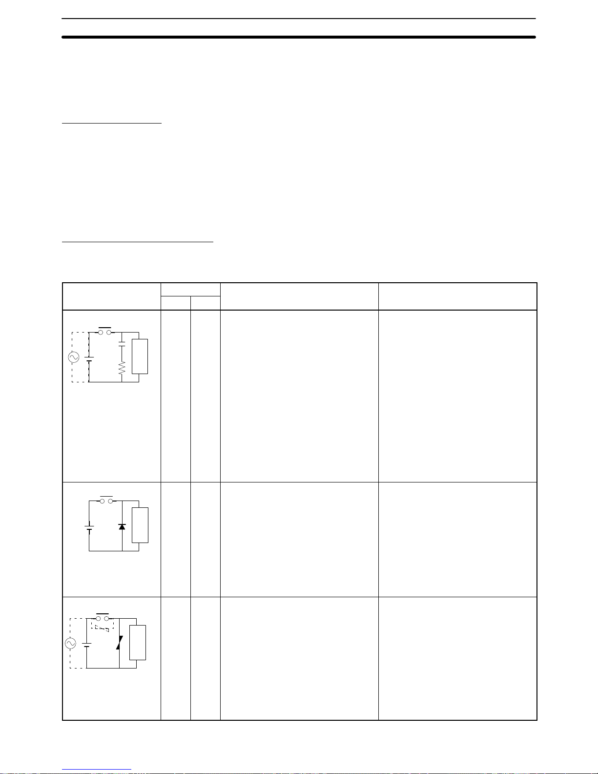
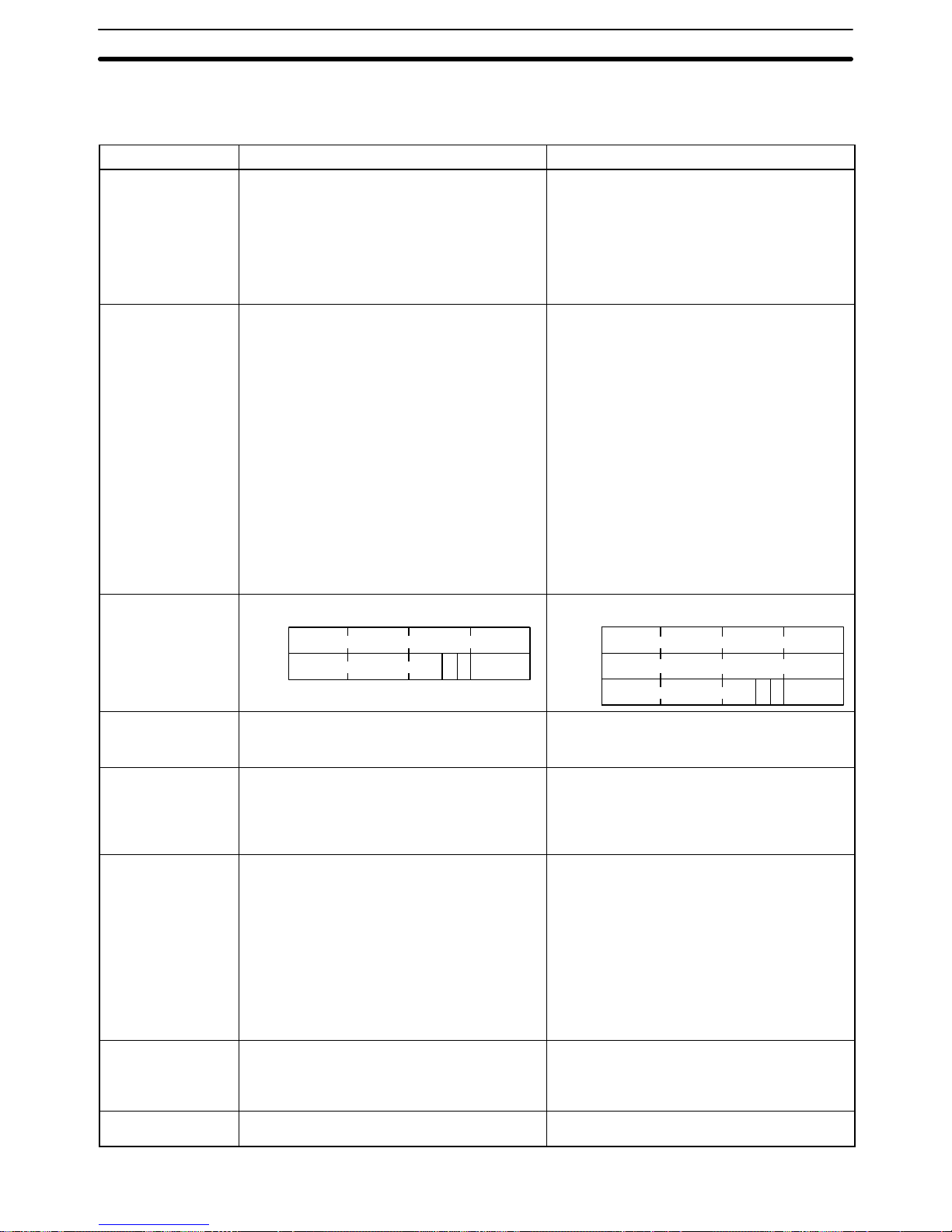
Countermeasure Examples
When switching an inductive load, connect a surge protector , diodes, etc., in parallel with the load or contact as shown below.
Circuit Current Characteristic Required element
AC DC
CR method
Power
supply
Inductive
load
Yes Yes If the load is a relay or solenoid, there
is a time lag between the moment the
circuit is opened and the moment the
load is reset.
If the supply voltage is 24 or 48 V,
insert the surge protector in parallel
with the load. If the supply voltage is
100 to 200 V, insert the surge
protector between the contacts.
The capacitance of the capacitor must
be 1 to 0.5 µF per contact current of
1 A and resistance of the resistor must
be 0.5 to 1 Ω per contact voltage of
1 V. These values, however, vary with
the load and the characteristics of the
relay. Decide these values from
testing, and take into consideration
that the capacitance suppresses spark
discharge when the contacts are
separated and the resistance limits
the current that flows into the load
when the circuit is closed again.
The dielectric strength of the capacitor
must be 200 to 300 V. If the circuit is
an AC circuit, use a capacitor with no
polarity.
Diode method
Power
supply
Inductive
load
No Yes The diode connected in parallel with
the load changes energy accumulated
by the coil into a current, which then
flows into the coil so that the current
will be converted into Joule heat by
the resistance of the inductive load.
This time lag, between the moment
the circuit is opened and the moment
the load is reset, caused by this
method is longer than that caused by
the CR method.
The reversed dielectric strength value
of the diode must be at least 10 times
as large as the circuit voltage value.
The forward current of the diode must
be the same as or larger than the load
current.
The reversed dielectric strength value
of the diode may be two to three times
larger than the supply voltage if the
surge protector is applied to electronic
circuits with low circuit voltages.
V aristor method
Power
supply
Inductive
load
Yes Yes The varistor method prevents the
imposition of high voltage between the
contacts by using the constant voltage
characteristic of the varistor. There is
time lag between the moment the
circuit is opened and the moment the
load is reset.
If the supply voltage is 24 or 48 V,
insert the varistor in parallel with the
load. If the supply voltage is 100 to
200 V, insert the varistor between the
contacts.
---
Page 16

6Conformance to EC Directives
xix
When switching a load with a high inrush current such as an incandescent lamp,
suppress the inrush current as shown below.
OUT
COM
R
OUT
COM
R
Countermeasure 1
Providing a dark current of approx.
one-third of the rated value through
an incandescent lamp
Countermeasure 2
Providing a limiting resistor
Page 17

1
SECTION 1
Introduction
This section describes the main features and basic functions of the DeviceNet (CompoBus/D) system and the DeviceNet
(CompoBus/D) Interface Unit.
1-1 Features of the DeviceNet Interface Unit 2. . . . . . . . . . . . . . . . . . . . . . . . . . . . . . . . . . . . . . .
1-2 DeviceNet Functions 3. . . . . . . . . . . . . . . . . . . . . . . . . . . . . . . . . . . . . . . . . . . . . . . . . . . . . .
1-2-1 DeviceNet Features 3. . . . . . . . . . . . . . . . . . . . . . . . . . . . . . . . . . . . . . . . . . . . . . . .
1-2-2 Communications Functions of Master Units 4. . . . . . . . . . . . . . . . . . . . . . . . . . . . .
1-2-3 DeviceNet (CompoBus/D) Communications Specifications 6. . . . . . . . . . . . . . . . .
1-3 System Configuration 7. . . . . . . . . . . . . . . . . . . . . . . . . . . . . . . . . . . . . . . . . . . . . . . . . . . . . .
1-3-1 Master Units 7. . . . . . . . . . . . . . . . . . . . . . . . . . . . . . . . . . . . . . . . . . . . . . . . . . . . . .
1-3-2 Example System Configuration 8. . . . . . . . . . . . . . . . . . . . . . . . . . . . . . . . . . . . . . .
1-4 Outline of Configurator 9. . . . . . . . . . . . . . . . . . . . . . . . . . . . . . . . . . . . . . . . . . . . . . . . . . . .
1-5 Functions of the DeviceNet (CompoBus/D) Interface Unit 10. . . . . . . . . . . . . . . . . . . . . . . . .
1-5-1 Communications Using the DeviceNet Interface Unit 10. . . . . . . . . . . . . . . . . . . . .
1-5-2 Contrast with the Regular Memory Link Method 11. . . . . . . . . . . . . . . . . . . . . . . . .
Page 18
1-1SectionFeatures of the DeviceNet Interface Unit
2
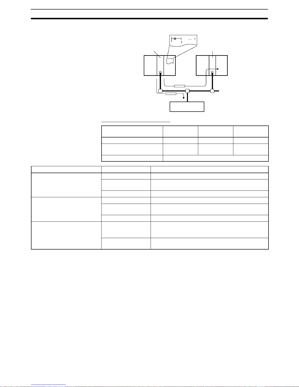
1-1 Features of the DeviceNet Interface Unit
The DeviceNet Interface Unit is an interface that connects PTs (Programmable
Terminals) to a DeviceNet network. The DeviceNet Interface Unit can connect
NT31, NT31C, NT631, and NT631C PTs.
DeviceNet is a industry-standard network, so the DeviceNet Interface Unit is
compatible with devices from different vendors. An OMRON PT can be controlled from another company’s Master when it is connected to the DeviceNet
network.
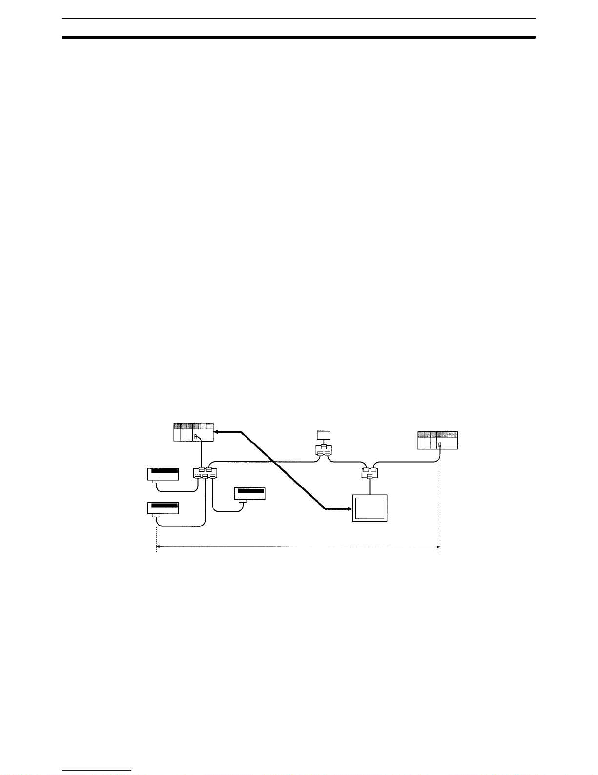
The DeviceNet Interface Unit allows a PT to be connected easily to an existing
DeviceNet network. Separate PT wiring is not required and wiring work is reduced. The DeviceNet network has a maximum communications distance of
500 m, so a PT in a remote location can be controlled from the Master.
The DeviceNet Interface Unit supports both remote I/O communications and explicit message communications.
• Remote I/O Communications
Remote I/O communications can exchange data (32 input words and 32 output words max.) with the PT at high speed and without programming, just like
regular I/O.
• Explicit Message Communications
More complicated control operations can be performed by sending explicit
messages from the Master when required.
A PT connected through the DeviceNet Interface Unit can execute simulated direct access with Memory Link. The PT can be controlled from the DeviceNet
Master that acts as the host by reading and writing PT memory within the PT.
Master
Data transfer and control
through remote I/O communications and explicit
message communications
Communications
power supply
T-branch Tap
Slave
(C200H I/O Link Unit)
Slave
Slave
T-branch Tap
with termination
T-branch Tap
with termination
Slave
PT connected to DeviceNet Interface Unit
Network length 500 m max.
Compatible with Other
Companies’ Masters
Easily Connect to an
Existing DeviceNet
Network
Supports Remote I/O and
Explicit Message
Communications
Memory Link Control
Page 19
1-2SectionDeviceNet Functions
3
1-2 DeviceNet Functions
1-2-1 DeviceNet Features
This section explains the features of the DeviceNet network.
The DeviceNet conforms to the DeviceNet open field network specification,
which means that devices (Masters and Slaves) produced by other manufacturers can be connected to the Network. A wide range of field-level applications can
thus be supported by combining valve devices, sensors, and other devices.
Remote I/O communications that constantly exchange I/O data between the
Master and Slaves can be executed simultaneously with message communications that send/receive Master Unit data as required by the application. A DeviceNet network can thus be installed to flexibly handle applications that require
both bit data and message data.
A Configurator (sold separately) can be used to enable connection of more than
one Master to the Network, allowing message communications between Masters and remote I/O communications between multiple groups of Masters and
Slaves. This allows the DeviceNet network to be used as a common bus to unify
controls while reducing wiring.
A Configurator (sold separately) can be used to enable mounting more than one
Master Unit to a single PC, allowing control of many more points. This feature
can easily handle line expansions and other applications.
A Configurator (sold separately) can be used to enable flexible allocation of I/O,
i.e., in any area and in any order. This allows I/O allocations that suit the application to simplify programming and enable effective usage of PC memory areas.
A Configurator (sold separately) can be used to set the communications cycle
time, enabling usage of Slaves with slow response times.
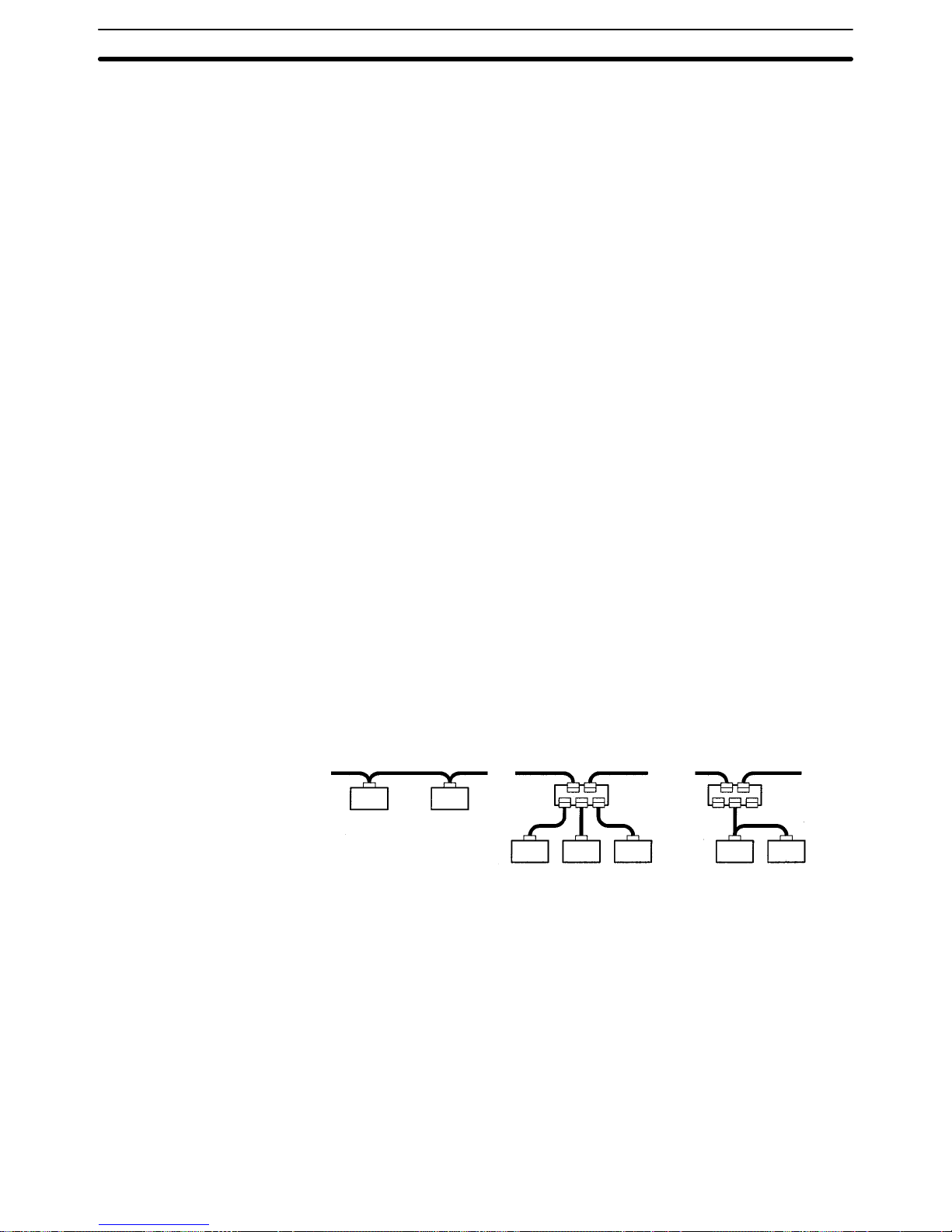
Use a multi-drop trunk line, T-branch multi-drop lines, or daisy-chain drop lines.
All three connection methods can be combined to flexibly construct a network
that meets the needs of the application.
Multi-drop trunk line
T-branch multi-drop line
Trunk line
Drop line
Daisy-chain
drop line
Multi-vendor Network
Simultaneous Remote I/O
and Message Services
Connect Multiple Masters
to the Same Network
Multi-layer Networks
Allow Multi-point Control
and Line Expansion
Free Remote I/O
Allocation
Handle Slaves with
Different Response
Speeds
Easily Expand or Change
Lines with Various
Connection Methods
Page 20
1-2SectionDeviceNet Functions
4
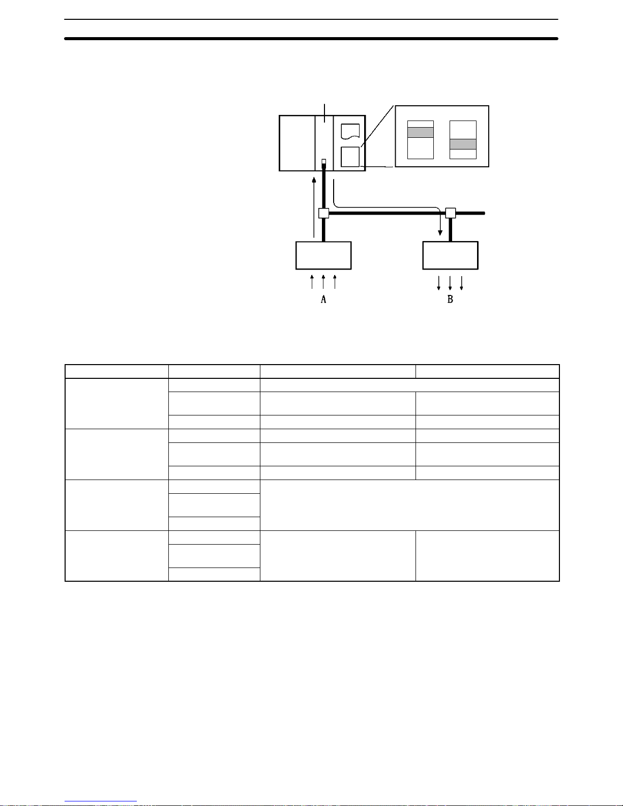
1-2-2 Communications Functions of Master Units
Remote I/O Communications
Master Unit
Output area Input area
Allocated in I/O memory
(e.g., IR/CIO Area)
Automatically input/output
Slave Slave
A
B
Note Input and output areas are automatically allocated in fixed areas unless a Confi-
gurator is used. A Configurator can be used to freely allocate input blocks 1 and
2, and output blocks 1 and 2, anywhere in I/O memory.
Item Master Unit model Without Configurator With Configurator
Max. number of Slave
CVM1, CV Series 63 nodes
nodes per Master
CS1 Series,
C200HZ/HX/HG/HE
50 nodes 63 nodes
C200HS 32 nodes 63 nodes
Max. number of control
CVM1, CV Series 2,048 pts (64 input/64 output words) 6,400 pts (100 words x 4 blocks)
points per Master
CS1 Series,
C200HZ/HX/HG/HE
1,600 pts (50 input/50 output words) Without messages: 4,800 pts
With messages: 1,600 pts
C200HS 1,024 pts (32 input/32 output words) 1,280 pts
Max. number of I/O
CVM1, CV Series
32 input/32 output words
points per Slave
controllable by Master
CS1 Series,
C200HZ/HX/HG/HE
C200HS
Remote I/O allocation
CVM1, CV Series
Fixed words in IR Area (or CIO area Any area
areas
CS1 Series,
C200HZ/HX/HG/HE
for CS1-series PCs)
C200HS
Reference Setting the number of words used by the DeviceNet Interface Unit changes the
maximum number of Units that can be connected in a single DeviceNet Network.
Page 21
1-2SectionDeviceNet Functions
5
Message Communications
Master Unit Master Unit
PT (DeviceNet
Interface Unit)
IOWR
Communications Instructions
Master Unit model Send Receive FINS
commands
CVM1, CV Series SEND(192) RECV(193) CMND(194)
CS1 Series,
C200HZ/HX/HG/HE
None None IOWR
C200HS ---
Item Master Unit model Capacity
Max. number of nodes per Master
CVM1, CV Series 8 nodes
Unit for message communications
using FINS commands
CS1 Series,
C200HZ/HX/HG/HE
8 nodes
C200HS Not supported
Max. number of nodes per Master
CVM1, CV Series 63 nodes
Unit for message communications
using explicit messages
CS1 Series,
C200HZ/HX/HG/HE
63 nodes
C200HS Not supported
Max. message length
CVM1, CV Series SEND(192): 152 bytes
RECV(193): 156 bytes
CMND(194): 160 bytes (starting with command code)
CS1 Series,
C200HZ/HX/HG/HE
IOWR: 160 bytes (starting with command code)
Reference 1. When sending explicit messages from an OMRON Master Unit, use the EX-
PLICIT MESSAGE SEND (28 01) FINS command.
2. The SEND and RECV instructions are used for communications between
OMRON Master Units; they are not used with the DeviceNet Interface Unit.
3. Explicit messages cannot be sent when a C200HS is used as the Master.
Page 22

1-2SectionDeviceNet Functions
6
1-2-3 DeviceNet (CompoBus/D) Communications Specifications
Item Specification
Communications protocol DeviceNet
Supported connections
(communications)
Master-Slave: Remote I/O and explicit messages
Peer-to-peer: FINS commands (see note 1)
Both conform to DeviceNet specifications
Connection forms (see note 2) Combination of multi-drop and T-branch
connections (for trunk or drop lines)
Baud rate 500 kbps, 250 kbps, or 125 kbps (switchable)
Communications media Special 5-wire cables (2 signal lines, 2 power
lines, 1 shield line)
Communications
distances
500 kbps Network length: 100 m max. (see note 3)
Drop line length: 6 m max.
Total drop line length: 39 m max.
250 kbps Network length: 250 m max. (see note 3)
Drop line length: 6 m max.
Total drop line length: 78 m max.
125 kbps Network length: 500 m max. (see note 3)
Drop line length: 6 m max.
Total drop line length: 156 m max.
Communications power supply 24 VDC supplied externally
Max. number of nodes 64 nodes (including Configurator when used)
Max. number of Masters Without Configurator:1
With Configurator: 63
Max. number of Slaves 63 Slaves
Communications cycle time
(see note 4)
Without Configurator: Calculated from conditions
Ex: Input Slaves (16-pt): 16
Output Slaves (16-pt) :16
Cycle time at 500 kbps: 9.7 ms
With Configurator: Set between 2 and 500 ms
Calculated value takes priority if longer.
Max. communications cycle
time with multiple Masters
(see note 5)
Calculated from conditions.
Ex: Input Slaves (16-pt): 16
Output Slaves (16-pt) :16
Max. cycle time at 500 kbps: 18 ms
Error control checks CRC error check
Note 1. FINS communications are not supported by the DeviceNet Interface Unit.
2. Terminating resistors are required at both ends of trunk line.
3. Indicates the length when thick cables are used. Reduce the network length
to 100 m max. when using thin cables. When using both thick and thin cables
together, refer to Combining Thick and Thin Cables in 3-2-2 Maximum Net-
work Length.
4. Indicates the maximum time for remote I/O communications from a Master
to a specific Slave until remote I/O communications are conducted again for
the same Slave.
5. The communications cycle time when more than one Master is present on a
single network.
Refer to t h e DeviceNet (CompoBus/D) Operation Manual (W267) for other com-
munications specifications, such as communications cycle times.
Page 23

1-3SectionSystem Configuration
7
1-3 System Configuration
A CompoBus/D (DeviceNet) system can be constructed in two ways: fixed allocation or free allocation.
A DeviceNet system can be constructed easily even without the Configurator.
With fixed allocation, predetermined words are allocated to each node for the
Slave’s I/O.
An OMRON Master Unit must be used in order to perform fixed allocation. Moreover, with fixed allocation only one Master Unit can be used in a DeviceNet network and only one Master Unit may be mounted to a PC.
The Configurator can be used to freely allocate the words used by each Slave.
With free allocation, more than one Master Unit can be connected in a Device-
Net network and each Master’s Slave I/O can be set independently. More than
one Master Unit may be mounted to each PC and those Masters can be used
independently. Furthermore, other companies’ Masters can be used.
Reference 1. The maximum number of words occupied by the DeviceNet Interface Unit is
32 input words and 32 output words. The number of input words and output
words can be set independently from 0 to 32 words. Do not allocate words
that are allocated to another Slave.
2. The maximum number of points controlled by each Master is lower with
fixed allocation than it is with free allocation. When the DeviceNet Interface
Unit is allocated a large number of words, do not exceed the maximum number of points that can be controlled by the Master. In particular , if a C200HS
is used as the Master with fixed allocation, the DeviceNet Interface Unit will
use all of the available points (32 input words and 32 output words) and it
won’t be possible to connect another Slave.
3. Each Master Unit and Configurator is connected as a single node in the DeviceNet network and requires a unique node number.
1-3-1 Master Units
The following OMRON Master Units are available.
Applicable PC Master Unit model Mounting position
Max. number of Units
number
With
Configurator
Without
Configurator
CVM1, CV Series CVM1-DRM21-V1 CPU or Expansion CPU Rack
(Classified as CPU Bus Units)
16
1
CS1 Series
C200HW-DRM21-V1 CPU Rack or Expansion I/O Rack
16
C200HZ/HX/HG/HE
(Classified as Special I/O Units)
10 or 16
(see note)
C200HS 10
Note Some CPUs can control 16 Master Units and other CPUs can control 10.
Fixed Allocation
Free Allocation
Page 24
1-3SectionSystem Configuration
8
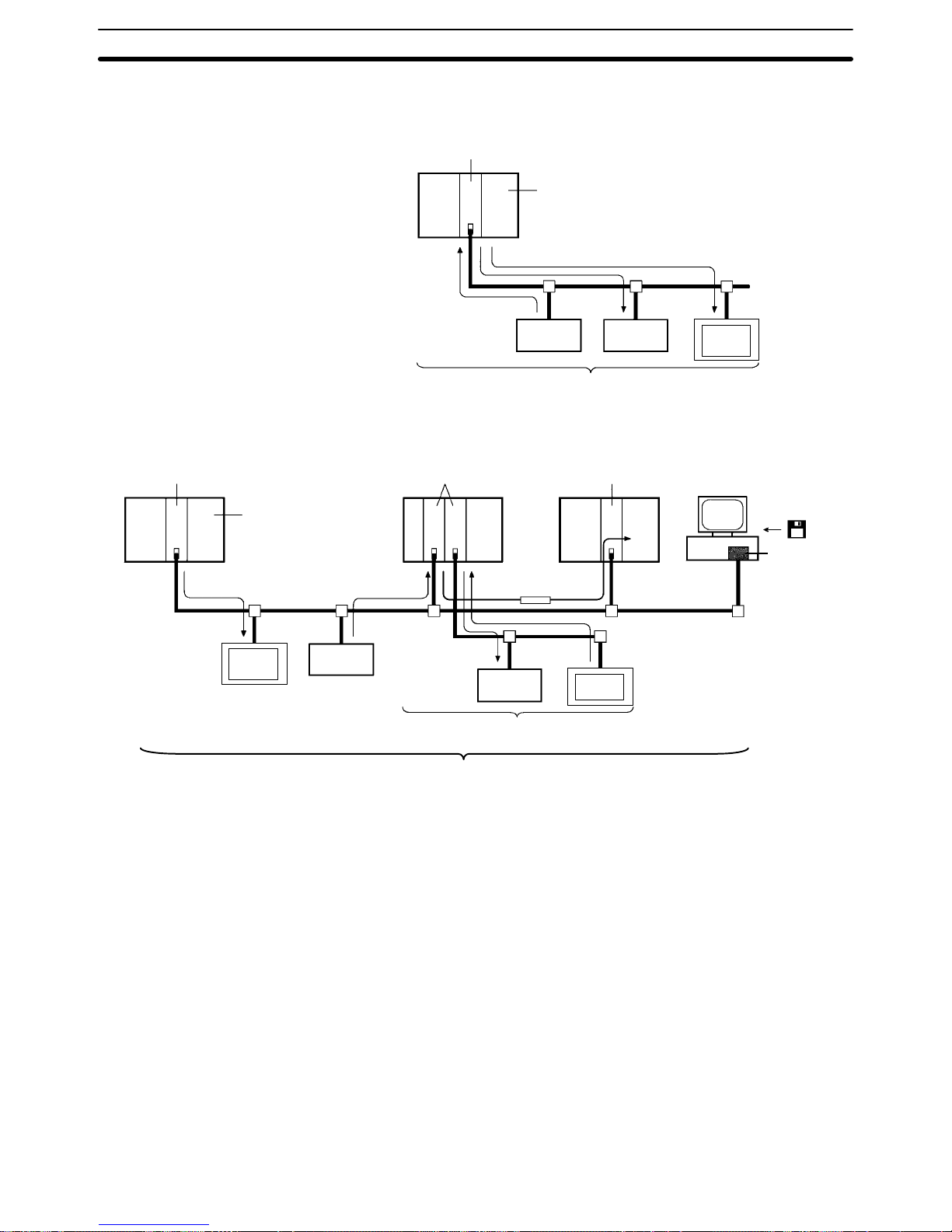
1-3-2 Example System Configuration
System Configuration without a Configurator (Fixed Allocation)
Master Unit
CPU Unit
Remote I/O communications
Slave Slave
CVM1/CV-series PCs: 64 nodes max.
CS1-series, C200HZ/HX/HG/HE PCs: 51 nodes max.
C200HS PCs: 33 nodes max.
PT
System Configuration with a Configurator (Free Allocation)
Master Unit
CPU Unit
Remote I/O communications
Slave
Slave
Master Unit Master Unit
Message
communications
Configurator
ISA Board
64 nodes max.
64 nodes max.
PT
PT
Page 25
1-4SectionOutline of Configurator
9
1-4 Outline of Configurator
The Configurator is required to use any of the following functions.
• User-set remote I/O allocations
• More than one Master Unit per PC (i.e., per CPU Unit)
• More than one Master Unit per network
• Setting communications parameters
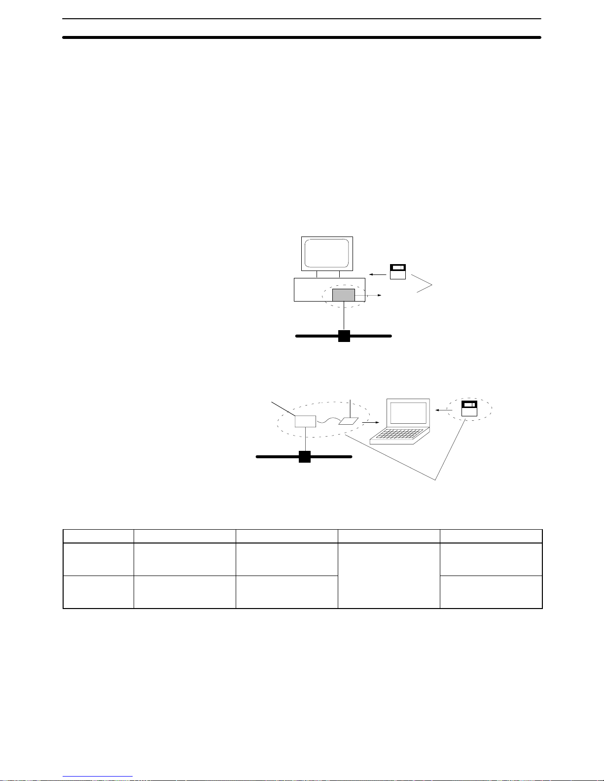
The Configurator is run on an IBM PC/AT or compatible computer connected to
the network as a DeviceNet node. Connection is made either through an ISA
Board or PCMCIA Card, as shown in the following diagrams. (The Configurator
can be removed from the network after settings have been completed.)
ISA Board in IBM PC/AT or Compatible
Configurator software
ISA Board
3G8F5-DRM21
PCMCIA Card in IBM PC/AT or Compatible
Configurator software
PCMCIA Card
3G8E2-DRM21
Network Interface Unit
Configurators
Model number Components Connector to network Applicable computer OS
3G8F5-DRM21 Dedicated ISA Board
and Configurator
Installation Disk
Dedicated ISA Board
IBM PC/AT or
compatible
Windows 95 or
Windows NT 3.51/4.0
3G8E2-DRM21 Dedicated PCMCIA
Card and Configurator
Installation Disk
Dedicated PCMCIA
Card
(See “Minimum System
Requirements” below.)
Windows 95
Minimum System Requirements
The minimum system requirements for an IBM PC/AT or compatible computer
are as follows:
CPU: i486/DX2 66 MHz min. (for Windows 95)
Pentium 90 MHz min. (for Windows NT)
Memory: 12 MB min., 16 MB recommended (for Windows 95)
16 MB min., 24 MB recommended (for Windows NT)
Hard disk: 5 MB of free space min.
Page 26

1-5SectionFunctions of the DeviceNet (CompoBus/D) Interface Unit
10
The main functions of the Configurator are illustrated below. For details, refer to
the DeviceNet (CompoBus/D) Configurator Operation Manual (W328).
Configurator
functions
Setup functions
Setting remote I/O allocations (scan list)
Setting other Master parameters (initial remote
I/O status, communications cycle time)
Setting Slave parameters for Slaves not from
OMRON
Monitoring functions
Displaying connected device lists
Monitoring Master status, Master error histories,
and communications cycle times
Operating functions
Starting/stopping remote I/O communications
File management functions
Reading/writing files for connected device data
(online) and device data resulting from setting
Master parameters (offline)
Note 1. Connect only one Configurator to each Network.
2. Do not use a Configurator in locations subjected to excessive noise, particularly when using a PCMCIA Card. Excessive noise will cause the computer
to run out of control. (This will not, however, adversely af fect the DeviceNet
network.)
3. The OMRON Configurator can only be used for OMRON Master Units
(CVM1-DRM21-V1, C200HW-DRM21-V1). Do not use the Configurator for
other company’s Master Units.
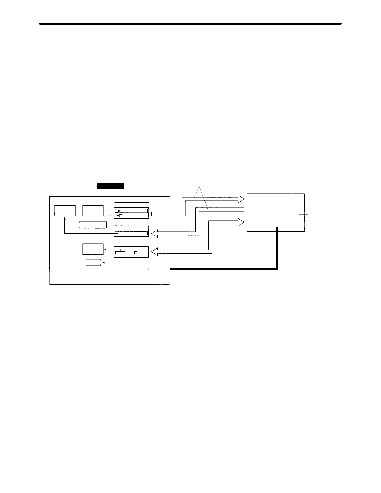
1-5 Functions of the DeviceNet (CompoBus/D) Interface Unit
A PT connected to the DeviceNet Interface Unit uses the Memory Link method.
In the Memory Link method, the PT memory area within the PT is treated as a
virtual PC memory area. This method allows PT memory and PT display elements to be accessed with simulated direct access.
1-5-1 Communications Using the DeviceNet Interface Unit
With the regular Memory Link method, the PT and host are connected through
RS-232C or RS-422A communications and the host controls the PT through the
PT memory by sending commands to the PT that read/write PT memory data.
When a DeviceNet Interface Unit is used, the PT is connected to the host (Master) through the DeviceNet network. In contrast to the regular Memory Link
method, PT memory is accessed using one of the following two methods.
The DeviceNet Interface Unit is connected to the network as a DeviceNet Slave.
As a DeviceNet Slave, the input and output areas can each contain up to 32
words.
In the DeviceNet system, the input area is regularly read by the Master and the
output area is regularly written from the Master. This process maintains consistency between the Slave’s input and output areas and the input and output areas
allocated to the Master.
Once the PT memory’s input and output areas have been set, PT memory can
be read and written without having the host (Master) manage communications.
The maximum size of the input and output areas is only 32 words each, but data
is transferred automatically at high speed so it is useful to allocate areas that require regular data transfers with the host such as the PT status control area and
PT status notify area or areas that are frequently refreshed such as the numeral
memory tables.
Parts of PT memory other than the input and output areas can be read/written by
sending explicit messages from the host.
Main Configurator
Functions
Accessing PT Memory
through Input and Output
Areas
Accessing PT Memory
with Explicit Message
Communications
Page 27
1-5SectionFunctions of the DeviceNet (CompoBus/D) Interface Unit
11
Transferring data with explicit message communications takes more time than
transferring data with the input and output areas, but all of PT memory can be
accessed.
If explicit message communications are used as the main method to transfer
data, the DeviceNet Interface Unit’s input and output areas can be reduced to
their minimum required sizes and more input and output area capacity will be
available for other Slaves.
Note Observe the following precautions in order to minimize the communications time
required for explicit message communications.
• Limit the amount of data transmitted in each message communications event.
• Consider setting the ladder program in the host that controls the DeviceNet In-
terface Unit so that it transfers just the data in the displayed screen. (In this
case, it will be necessary to write a ladder program section for each screen.)
PT
Remote I/O
communications
Master Unit
CPU Unit
PT status
control area
PT status
notify area
Touch switch
Numeral
memory
table
Direct access
PT memory
Input
area
Output
area
DeviceNet Network
Explicit message communications (Transfers
data in any area.)
Lamp
1-5-2 Contrast with the Regular Memory Link Method
The following operations are different with the DeviceNet Interface Unit and with
regular Memory Link method.
• The transmission direction of the input area is always PT → Host and that of
the output area is always Host → PT, so two-way functions cannot be used
when using the input and output areas.
• Except for remote I/O communications, no locally-initiated communications
functions are supported by the DeviceNet Interface Unit. With explicit message communications, communications are always executed by commands
sent from the host and corresponding responses from the PT.
• Since the DeviceNet Interface Unit does not support locally-initiated communications functions other than remote I/O communications, it is necessary to
set the strobe ON interval to match system requirements and always read the
status of the strobe at the Master. (Set the interval in the system menu.)
The following table lists the operational differences between the regular Memory
Link and the DeviceNet Interface Unit’s Memory Link that arise due to differ-
Page 28
1-5SectionFunctions of the DeviceNet (CompoBus/D) Interface Unit
12
ences described above and differences in the hardware used for communications.
Item With Regular Memory Link With DeviceNet Interface Unit
Communications
with host (method
used to read/write
PT memory)
Data transfer by Memory Link commands via
RS-232C or RS-422A communications
• Data transfer through the DeviceNet input and
output areas (The contents of corresponding
words in the host are updated automatically.)
• Data transfer by explicit message communications
Refer to 1-5-1 Communications Using the
DeviceNet Interface Unit for more details.
Functions possible
between the PT and
host
The following functions can be executed with
the Memory Link command:
• Read/write PT memory, numeral memory
tables, character string tables, or bit memory
tables.
• Clear numeral memory tables, character string
tables, or bit memory tables.
• Notify the host of a touch switch, numeral, or
character input.
• Notify the host of a change in the direct area or
PT memory.
• Change the PT’s operating mode.
• Send a resend request to the PT.
• Return an error response to an illegal command
from the host.
The following functions can be executed by
sending explicit messages:
• Read/write PT memory.
(Data is automatically transferred through the
input and output areas. Data can be transferred
to or from any area with explicit message communications.)
Structure of the PT
status notify area
PT status notify bits
00 0
Bit
15 14 13 12 11 10 9 8 7 6 5 4 3 2 1 0
Word m
Word m+1
Word
Numeral/character string memory table number
(4-digit BCD or hexadecimal)
Bit
Screen number (4 BCD digits)
Numeral/character string memory table number
(4-digit BCD or hexadecimal)
15 14 13 12 11 10 9 8 7 6 5 4 3 2 1 0
Word m
Word m+1
Word m+2
Word
00 0PT status notify bits
PT status notify
area’s “Displayed
screen number”
None
(The current screen number can be found in
the PT status control area’s “screen number”.)
Notify the host of the displayed screen number.
Strobe of the PT
status notify area’s
“PT status notify bit”
The strobe goes ON for a fixed time when the
displayed screen is changed or the contents of
the numeral or character string memory table
are changed. (At the same time, the host is
notified by the Memory Link command.)
The strobe goes ON for time set in the system
menu. (There is no notification to the host. The
strobe’s ON time must be longer than the
interval between data reads from the host.)
Window control
area
Normally, this area is used in both directions
and the contents of this area are mirrored in the
corresponding area in the host.
• Specification of the displayed window from the
host to the PT
• Notification of the displayed window from the
PT to the host
• When allocated to the input area, only notification of the displayed window from the PT to the
host is performed.
• When allocated to the output area, only specification of the displayed window from the host to
the PT is performed.
• When allocated to an area other than the input
or output area, it is necessary to regularly read
the contents to recognize changes and write
data to control the displayed window.
Notification to the
host
Notify the host with the notification command. None. (The user must confirm contents by
regularly reading data at the locations where
changes are expected or allocating part of the
input area so that data is read automatically.)
System program in
the PT
Use the factory-installed system program or the
system program included with the Support Tool.
Install the system program included with the
DeviceNet Interface Unit.
Page 29

1-5SectionFunctions of the DeviceNet (CompoBus/D) Interface Unit
13
Item With DeviceNet Interface UnitWith Regular Memory Link
Simultaneous use
with the Memory
Unit
Possible The Memory Unit cannot be used because the
DeviceNet Interface Unit also uses the
Expansion Interface Connector on the back of
the PT. (It is possible to reconnect the Memory
Unit and save data such as the DeviceNet
Interface Unit’s screen data.)
Use of the RS-422A
port
Possible (for communications with the host) Not possible (A bar code reader or computer
running Support Tool can be connected to the
RS-232C port.)
Any functions that are not listed in the table above are identical with the regular
Memory Link and the Memory Link used with the DeviceNet Interface Unit. Communications between the PT and host are different between the regular Memory
Link and the Memory Link used with the DeviceNet Interface Unit, but data exchange between the PT (parts, memory tables, etc.) and PT memory are the
same.
This manual explains only the functions particular to the DeviceNet Interface
Unit and their usage. Refer to the appropriate manual listed below for details on
procedures such as operating the PT and creating screens.
• NT31/NT31C setup and connections:
NT31/NT31C Setup Manual (V062)
• NT631/NT631C setup and connections:
NT631/NT631C Setup Manual (V063)
• NT31/NT31C and NT631/NT631C functions and control:
NT31/NT631 Reference Manual (V064)
• Support Tool operations and operations such as creating screens:
NT-series Support Tool Operation Manual (V061)
Note The manuals listed above cover the “-V2” versions of the NT31/NT31C and
NT631/NT631C, but the PT will operate as a “-V1” version when the DeviceNet
Interface Unit is connected so some functions listed in the manuals will not be
usable. Refer to Appendix B for details on differences between functions in the
“-V1” versions (system version 2.1) and the “-V2” versions.
Page 30

15
SECTION 2
Operating Procedures
This section shows a simple system configuration example and basic procedures up to using the PT connected to the DeviceNet Interface Unit.
2-1 Operating Procedures Flowchart 16. . . . . . . . . . . . . . . . . . . . . . . . . . . . . . . . . . . . . . . . . . . . .
2-1-1 PT Settings Procedure 16. . . . . . . . . . . . . . . . . . . . . . . . . . . . . . . . . . . . . . . . . . . . . .
2-1-2 Flowchart 17. . . . . . . . . . . . . . . . . . . . . . . . . . . . . . . . . . . . . . . . . . . . . . . . . . . . . . . .
2-1-3 Preparations prior to Communications 18. . . . . . . . . . . . . . . . . . . . . . . . . . . . . . . . .
2-1-4 Setting Up Communications 18. . . . . . . . . . . . . . . . . . . . . . . . . . . . . . . . . . . . . . . . .
2-1-5 Starting Remote I/O Communications During Operation 20. . . . . . . . . . . . . . . . . . .
2-2 Simple System Configuration 20. . . . . . . . . . . . . . . . . . . . . . . . . . . . . . . . . . . . . . . . . . . . . . .
Page 31

2-1SectionOperating Procedures Flowchart
16
2-1 Operating Procedures Flowchart
This section shows a flowchart of the basic operating procedures up to using the
PT connected to the DeviceNet Interface Unit.
2-1-1 PT Settings Procedure
Turn ON the PT’s power supply.
Setting the PT Memory’s Input
and Output Areas
Download the system program.
Turn OFF the PT’s power supply.
Mount the DeviceNet Interface Unit.
Turn ON the PT’s power supply.
Settings in the PT’s system menu
(DeviceNet Software Switch settings)
• Output area’s starting PT memory word
Example: PM0100
• Size of output area
Example: 32 words
• Input area’s starting PT memory word
Example: PM0200
• Size of input area
Example: 32 words
• Communications speed
• Local node number
• Strobe ON time setting
Transfer screen data.
Turn OFF the PT’s power supply.
Setup the DeviceNet network.
Turn ON the PT’s power supply.
PC vendor: Memory Link
Setting the PT Configuration with
the NT-series Support Tool
PT status control area
Example: PM0100 to PM0104
PT status notify area
Example: PM0200 to PM0202
Specify PC addresses for parts:
LED: PM010515
Touch switch input notification:
PM020300
Numeral memory table #0:
PM0106 and PM0107
Page 32
2-1SectionOperating Procedures Flowchart
17
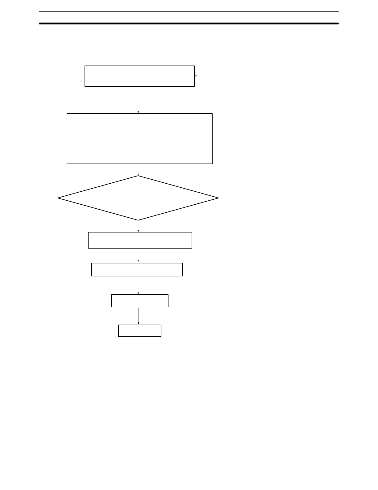
2-1-2 Flowchart
The following flowchart outlines the basic flow of operations for setting up the
DeviceNet system.
(1)
(2)
Check
Yes
(3)
(4)
(5)
No
Determine a suitable baud rate for the
user’s system.
Determine the node arrangement, the wiring configuration, and the cable lengths.
A) Restrictions on lengths of trunk lines and drop
lines and total drop line length. (Selection of
thick cables or thin cables)
B) Separation from noise sources.
Do (1) and (2) above meet the
DeviceNet specifications?
Refer to the DeviceNet (CompoBus/D) Op-
eration Manual (W267).
Refer to Section 3 Network Design.
Determine the method for providing a
communications power supply.
Refer to Section 3-3 Sharing the Communications
Power Supply.
Arrange for the required devices.
Refer to Section 4 Installation and Network Connection,
Appendix B, the DeviceNet (CompoBus/D) Operation
Manual, the DeviceNet (CompoBus/D) Slaves Operation
Manual, or the DeviceNet (CompoBus/D) MULTIPLE I/O
TERMINAL Operation Manual.
Purchase devices.
Installation
Refer to Section 4 Installation and Network Connection.
Page 33

2-1SectionOperating Procedures Flowchart
18
2-1-3 Preparations prior to Communications
1, 2, 3... 1. Set the initial settings for the Master Unit:
Unit number (“UNIT No.” or “MACHINE No.” on front panel switch)
Node address (back panel DIP switch)
Baud rate (back panel DIP switch)
Communications continue/stop setting for communications error (front panel switch)
2. Mount the Master Unit and wire the Network.
For CVM1 and CV-series PCs, Master Units are treated as CPU Bus Units
and can be mounted to the CPU Rack or Expansion CPU Rack. Only one
Master Unit can mounted if a Configurator is not used, but up to 16 Master
Units can be mounted if a Configurator is used.
For C200HX/HG/HE PCs, Masters are treated as Special I/O Units and can
be mounted to the CPU Rack or Expansion I/O Rack. Only one Master Unit
can be mounted if a Configurator is not used, but up to 10 or 16 Master Units
can be mounted if a Configurator is used.
For CS1-series PCs, Masters are treated as Special I/O Units and can be
mounted to the CPU Rack or Expansion I/O Rack. Only one Master Unit can
be mounted if a Configurator is not used, but up to 16 Master Units can be
mounted if a Configurator is used.
For C200HS PCs, Masters are treated as Special I/O Units and can be
mounted to the CPU Rack or Expansion I/O Rack. Only one Master Unit can
be mounted if a Configurator is not used, but up to 10 Master Units can be
mounted if a Configurator is used.
3. Connect a Programming Device to the PC and turn ON the power supply to
the PC.
4. Generate the I/O table.
2-1-4 Setting Up Communications
Remote I/O Communications with One Master Unit in the Network
Always operate with the scan list enabled. Refer to the DeviceNet (CompoBus/D) Operation Manual (W267) for details on connecting more than one Mas-
ter Unit in a single network.
1, 2, 3... 1. Turn ON the communications power supply and then the power supply to
the Slaves (i.e., the PT).
2. Turn ON the power supply to the Master (i.e., the PC).
3. Switch the PC to PROGRAM mode.
4. If the scan list was disabled at startup, perform the following and go to step 7.
(Otherwise, proceed to step 5.)
a) Confirm that communications are possible with the registered Slaves
(i.e., the PT) by monitoring the Master’s Registered Slave Data Area.
b) From a Programming Device connected to the PC, turn ON the Scan List
Enable Bit in the Master’s software switches (bit 0).
Remote I/O communications will start with the scan list enabled. You can
use the Master’s software switches to start and stop remote I/O communications.
5. If the scan list was disabled at startup and you want to re-register it, perform
the following from a Programming Device connected to the PC and go to
step 7. (Otherwise, proceed to step 6.)
a) Turn ON the Scan List Clear Bit in the Master’s software switches (bit 1).
b) Confirm that communications are possible with the registered Slaves by
monitoring the Master’s Registered Slave Data Area.
Using Fixed I/O
Allocations
Page 34

2-1SectionOperating Procedures Flowchart
19
c) Turn ON the Scan List Enable Bit in the Master’s software switches (bit
0).
Remote I/O communications will start with the scan list enabled. You can
use the Master’s software switches to start and stop remote I/O communications.
6. Do nothing if the scan list was enabled at startup and you do not want to
change it.
Remote I/O communications will start with the scan list enabled. You can
use the Master’s software switches to start and stop remote I/O communications. Go to step 7.
7. Confirm that the MS and NS indicators on all Master Units and Slaves (i.e.,
the PT) are lit green.
8. Switch the PC to RUN mode.
Note The dots on the 7-segment display on the Master Unit can be used to determine
if the scan list is enabled or disabled. If both the right and left dots are not lit, the
scan list is enabled. If both dots are lit, the scan list is disabled.
Always operate with the scan list enabled. Refer to the DeviceNet (Compo-
Bus/D) Operation Manual (W267) for details on connecting more than one Master Unit in a single network.
1, 2, 3... 1. Connect a Configurator to the Network.
2. Turn ON the communications power supply and then the power supply to
the Slaves (i.e., the PT).
3. Turn ON the power supply to the Master (i.e., the PC).
4. Switch the PC to PROGRAM mode.
5. Create the Master parameters with the Configurator.
6. Register the Master parameters in the Master Unit.
Remote I/O communications will start with the scan list enabled. (Commu-
nications will not start at if they have been set to be stopped at startup from
the Configurator.) Use the software switches or Configurator to start and
stop remote I/O communications.
7. Confirm that the MS and NS indicators on all Master Units and Slaves (i.e.,
the PT) are lit green.
8. Read the Network configuration from the Configurator.
9. Save the Network configuration in a file from the Configurator.
10. Switch the PC to RUN mode.
Using Free (User-set) I/O
Allocations
Page 35

2-2SectionSimple System Configuration
20
2-1-5 Starting Remote I/O Communications During Operation
1, 2, 3... 1. Turn ON the communications power supply and then the power supply to
the Slaves (i.e., the PT).
2. Turn ON the power supply to the Master (i.e., the PC).
3. Switch the PC to RUN mode.
Reference It is alright to turn ON the following power supplies simultaneously. If the power
supplies cannot be turned ON simultaneously, turn them ON in the order listed
above.
Communications power supply and Slave (PT) power supply
Slave (PT) power supply and Master Unit (PC) power supply
All three power supplies
Observe the following precautions:
• Use a DC power supply with low voltage fluctuation.
• If the Slave’s (PT’s) power supply is turned ON before the communications
power supply , the Slave (PT) might not be added to the network.Turn the power supplies ON simultaneously or turn ON the communications power supply
first.
• Always operate the Master Unit with the scan list enabled.
By operating with the scan list enabled, the Master can determine whether or
not the Slave (PT) is participating in the network so the user can check whether
the DeviceNet network is operating normally.
2-2 Simple System Configuration
OMRON manufactures a variety of devices that are compatible with the DeviceNet standard, including devices that handle bit I/O, temperature inputs, analog
I/O, and other functions. Moreover, devices manufactured by other companies
can be connected if they conform to DeviceNet standards.
It is also easy to change the configuration of a DeviceNet network since just one
cable is required for wiring.
Master
Communications
power supply
Slave
(C200H I/O Link Unit)
T-branch Tap
Slave
(Remote I/O
Terminal)
T-branch Tap with
Terminating Resistor
T-branch Tap
with Terminating
Resistor
Slave
(Temperature
Input Terminal)
PT connected to DeviceNet Interface Unit
Slave
(Remote I/O
Terminal)
A PT connected to the network through a DeviceNet Interface Unit can perform
some of the functions of a control panel, such as switch operations and numeric
inputs as well as displaying the system’s operating status.
Precautions
Page 36

21
SECTION 3
Network Design
This section provides information required when designing a network, such as precautions regarding the configuration of the
DeviceNet network to which the CompoBus/D Interface Unit connects.
3-1 Network Configuration 22. . . . . . . . . . . . . . . . . . . . . . . . . . . . . . . . . . . . . . . . . . . . . . . . . . . .
3-1-1 Network Components 22. . . . . . . . . . . . . . . . . . . . . . . . . . . . . . . . . . . . . . . . . . . . . .
3-1-2 Connections 23. . . . . . . . . . . . . . . . . . . . . . . . . . . . . . . . . . . . . . . . . . . . . . . . . . . . . .
3-2 Limitations on the Network Configuration 24. . . . . . . . . . . . . . . . . . . . . . . . . . . . . . . . . . . . .
3-2-1 Baud Rate and Communications Distance 24. . . . . . . . . . . . . . . . . . . . . . . . . . . . . . .
3-2-2 Maximum Network Length 24. . . . . . . . . . . . . . . . . . . . . . . . . . . . . . . . . . . . . . . . . .
3-2-3 Drop Line Lengths 25. . . . . . . . . . . . . . . . . . . . . . . . . . . . . . . . . . . . . . . . . . . . . . . . .
3-2-4 Total Drop Line Length 26. . . . . . . . . . . . . . . . . . . . . . . . . . . . . . . . . . . . . . . . . . . . .
3-2-5 Locating Terminating Resistors 26. . . . . . . . . . . . . . . . . . . . . . . . . . . . . . . . . . . . . . .
3-3 Sharing the Communications Power Supply 27. . . . . . . . . . . . . . . . . . . . . . . . . . . . . . . . . . . .
3-3-1 Prerequisite Conditions 27. . . . . . . . . . . . . . . . . . . . . . . . . . . . . . . . . . . . . . . . . . . . .
3-3-2 Determining the Communications Power Supply Method 28. . . . . . . . . . . . . . . . . .
3-3-3 Locating the Power Supply 29. . . . . . . . . . . . . . . . . . . . . . . . . . . . . . . . . . . . . . . . . .
3-3-4 Step 1: Determining the Best Location for the Power Supply from a Graph 30. . . .
3-3-5 Step 2: Calculating the Best Location of the Actual Nodes 33. . . . . . . . . . . . . . . . .
3-3-6 Step 3: Splitting the System into Multiple Power Supplies 36. . . . . . . . . . . . . . . . . .
3-3-7 Dual Power Supply 37. . . . . . . . . . . . . . . . . . . . . . . . . . . . . . . . . . . . . . . . . . . . . . . .
3-4 Grounding the Network 37. . . . . . . . . . . . . . . . . . . . . . . . . . . . . . . . . . . . . . . . . . . . . . . . . . . .
3-4-1 Ground Wire Connection 38. . . . . . . . . . . . . . . . . . . . . . . . . . . . . . . . . . . . . . . . . . . .
3-5 Noise Precautions 38. . . . . . . . . . . . . . . . . . . . . . . . . . . . . . . . . . . . . . . . . . . . . . . . . . . . . . . . .
3-6 Correcting Faulty Operation Caused by Noise 40. . . . . . . . . . . . . . . . . . . . . . . . . . . . . . . . . .
3-7 Sharing the Same Power Supply 40. . . . . . . . . . . . . . . . . . . . . . . . . . . . . . . . . . . . . . . . . . . . .
Page 37
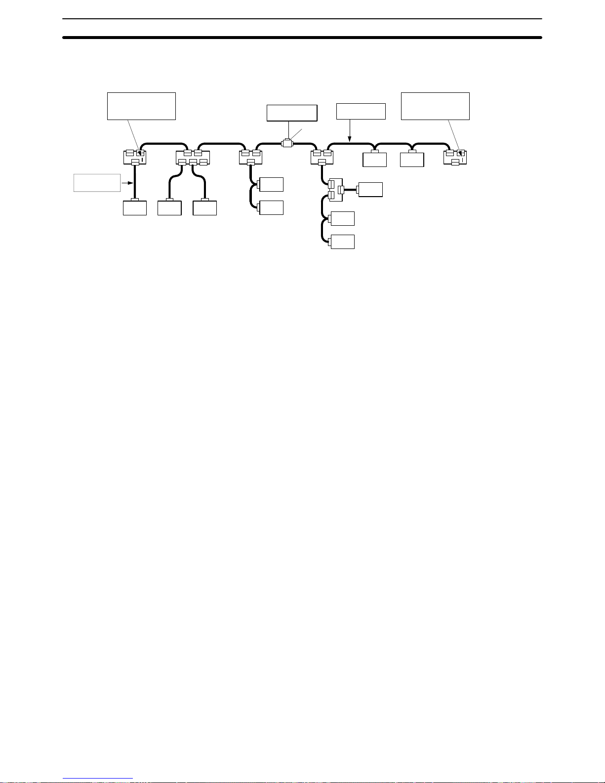
3-1SectionNetwork Configuration
22
3-1 Network Configuration
The following diagram shows the configuration of a DeviceNet network.
DeviceNet
cables are used.
T: T-branch connection
M: Multi-drop connection
DeviceNet cables (5-wire cables) are
used for the trunk lines and drop lines.
Node
Drop line
Drop line
Drop line
T-branch
Tap
Drop line
Drop line
Trunk line Trunk line Trunk line
Trunk
line
Trunk line Trunk line
Node
Node
Node
Node
Node
Node
Node
Node
Node
TT TT
M
M
T
M
MM
T
Terminating Resistors
are connected at each
end of the trunk line.
Power Supply Tap
or T-branch Tap
24 VDC
Communications
power supply
DeviceNet
Cables are used.
T-branch
Tap
T-branch
Tap
T-branch
Tap
Drop line Drop line
T-branch
Tap
T-branch Tap
Terminating Resistors
are connected at each
end of the trunk line.
3-1-1 Network Components
There are two kinds of nodes in a DeviceNet network. The Slaves connect to
external I/O and the Master administers the Network and manages the external
I/O of the Slaves. (There are also Slaves that exchange data with devices such
as the CPU Unit and PTs.) The Master and Slaves can be connected at any location in the Network, as shown in the preceding diagram.
The trunk line refers to the cable that has Terminating Resistors on both ends.
Cables branching from the trunk line are known as drop lines. The trunk line
length does not necessarily coincide with the maximum length of the Network.
DeviceNet communications are transmitted through 5-wire cables. The cables
come in thick or thin versions.
Two methods can be used to connect DeviceNet nodes: The T-branch method
and the multi-drop method. With the T-branch method, the node is connected to
a drop line created with a T-branch Tap. With the multi-drop method, the node is
directly connected to the trunk line or the drop line. Secondary branches can be
made from a drop line. Both of these connection methods can be used in the
same Network, as shown in the example.
Terminating Resistors are connected at each end of the trunk line to reduce signal reflection and stabilize communications. There are two kinds of Terminating
Resistors available, one for a T-branch Tap and one for a Terminating-block Terminating Resistor. Use a DeviceNet cable when connecting a Terminating-block
Terminating Resistor.
To use DeviceNet, connect a communications power supply to the communications connector of each node with a 5-wire cable. Basically, a communications
power supply, internal circuit power supply, and I/O power supply must be provided separately. (Refer to 3-7 Sharing the Same Power Supply for details.)
Note 1. Always use 5-wire DeviceNet cables.
2. Connect Terminating Resistors to both ends of the trunk line. When using a
Terminating-block Terminating Resistor, use a DeviceNet cable to connect
the Terminating Resistor. When connecting the Terminating Resistor, insulate the power supply lines that are not being used with vinyl electrical tape
to avoid a short-circuit in the cables.
3. Do not use products other than DeviceNet products (for example, a lightning
arrester) in the communications path. Using other products can interfere
with normal communications by causing signal reflections and other problems.
Nodes
Trunk/Drop Lines
Connection Methods
Terminating Resistors
Communications Power
Supplies
Page 38

3-1SectionNetwork Configuration
23
3-1-2 Connections
The trunk line is a cable to which Terminating Resistors are connected at the
ends. Drop lines are cables that branch from the trunk lines. A special 5-wire
cable is used for both the trunk lines and the drop lines.
Branching Patterns
Branching Patterns from Trunk Line
Drop line
T-branch Tap
Trunk line
Node
Trunk line
T-branch Tap
Trunk line
Node
T-branch Tap
Node
Node
Trunk line
Multi-drop
Trunk line
Node
Trunk line
1.One drop line from
trunk line
2.Three drop lines (maximum)
from trunk line
3.Node connected directly to
trunk line
Branching Patterns from Drop Line
Drop line
T-branch Tap
Trunk line
Node
Trunk line
T-branch Tap
Trunk line
Node
T-branch Tap
Node
Node
Trunk line
Multi-drop
Trunk line
Node
Trunk line
4 One drop line from
drop line
5.Three drop lines (maximum)
from drop line
6.Node connected directly to
drop line
V arious combinations of branching patterns can be used on the same network,
as shown in the following diagram. Any number of nodes up to 63 can be connected onto a single drop line.
Communications
power supply
Terminating
Resistor
Node Node
Drop line
NodeNode
Drop
line
Trunk line
24 VDC
Node
Node
Node
Node
Node
Node
Power Supply Tap
or T-branch Tap
Trunk line
Drop
line
Terminating
Resistor
Reference 1. A node can be connected directly to the trunk line with the multi-drop meth-
od, but it is easier to connect a node to a drop line.
2. Multi-drop connections with thick cables cannot be used with the connectors
supplied with the Unit because the cables are too thick. Use the following
connectors for multi-drop connections with thick cables. (For further details,
refer to Appendix C Standard Models.)
XW4B 05C4-T-D (w/o set screw) (made by OMRON)
Use a T-branch Tap instead if the connector extends too far from the side of
the Master Unit or DeviceNet Interface Unit and interferes with the Unit in the
adjacent slot.
3. When using thick cable, wire the cable with enough extra cable so that the
connector won’t become disconnected accidentally when pulled.
Trunk and Drop Lines
Page 39
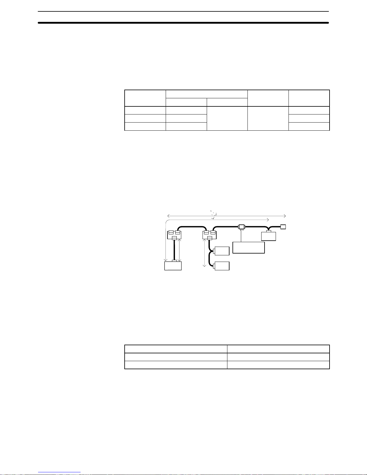
3-2SectionLimitations on the Network Configuration
24
3-2 Limitations on the Network Configuration
3-2-1 Baud Rate and Communications Distance
The communications distance in a DeviceNet network is also restricted by the
baud rate, as shown in the following table.
Baud rate
Maximum network length
Drop line Total drop
Thick cable Thin cable
length line length
500 kbps 100 m max.
100 m max. 6 m max.
39 m max.
250 kbps 250 m max. 78 m max.
125 kbps 500 m max. 156 m max.
Note Always keep the communications distance within the limits shown in this table.
3-2-2 Maximum Network Length
The length of the network is longest at either the distance between the two most
distant nodes or at the distance between the Terminating Resistors.
Node
Length of
drop line
Node
Communications
power supply
Node
Terminal-block
Terminating Resistor
T-branch Tap with
Terminating Resistor
Longest distance is the maximum network length
Length of
drop line
Node
There are two types of cables: Thick cables and thin cables. The thick cables are
relatively hard and inflexible, but they protect against signal attenuation and can
be used for relatively long communications distances. The thin cables are soft
and flexible, but they do not protect as well against signal attenuation and are not
suited to long communications distances.
The maximum length of a network thus depends on the type of cable that is used,
as shown in the following table.
Cable type Maximum network length
Thick cables (5-wire) 500 m
Thin cables (5-wire) 100 m
Reference a) If the length of the network is 100 meters or less, the thin cables
can be used for the trunk line. When using thin cables for the trunk
line, be sure that communications power supply conditions are
met. Refer to 3-3 Sharing the Communications Power Supply.
b) The length of the network is also restricted by the baud rate used.
Even with thick cables, the length of the network will be restricted if
the baud rate is set to anything but 125 kbps. Refer to 3-2-1 Baud
Rate and Communications Distance above.
Page 40

3-2SectionLimitations on the Network Configuration
25
Note Combining Thick and Thin Cables
The most distant nodes can also be connected by a combination of thin and thick
cables. When the s e c a b l e s are combined, the following conditions must be met
and the maximum network length will be shorter than when only thick cables are
used. Also, when combining cables, be sure that the maximum current capacity
of the cables is not exceeded. Refer to 3-3 Sharing the Communications Power
Supply.
Baud rate Maximum network length
500 kbps
L
THICK
+ L
THIN
100 m
250 kbps
L
THICK
+ 2.5 x L
THIN
250 m
125 kbps
L
THICK
+ 5 x L
THIN
500 m
L
THICK
: Length of the thick cable; L
THIN:
Length of thin cable
Configuration Example
Communications
power supply
Node
6 m
Node
Node
Node
Terminal block
with Terminating Resistor
Maximum network length
thin
cable
24 m
Thin cable
125 m
Thick cable
20 m
Thin cable
1 m
L
THICK
+ L
THIN
= 175 100 m
500 kbps NG
L
THICK
+ 2.5 x L
THIN
= 125 + 2.5 x 50 = 250 250 m
250 kbps OK
L
THICK
+ 5 x L
THIN
= 125 + 5 x 50 = 375 500 m
125 kbps OK
The results of the above formulas indicate that 250 kbps and 125 kbps can be
used as the baud rates for this configuration example.
Even when the above conditions are met, however, the current flowing through
the cables must not exceed the permissible current capacity. ( Refer to 3-3 Shar-
ing the Communications Power Supply.)
3-2-3 Drop Line Lengths
A drop line length is measured from the point in the trunk line where the original
branch was made to the end of the branch. The maximum length of a drop line is
6 m. It is possible to make a secondary branch from a drop line.
Page 41

3-2SectionLimitations on the Network Configuration
26
3-2-4 Total Drop Line Length
This is the total sum length of all the drop lines. Even when the length of each
individual drop line is 6 m or less, be sure not to exceed the maximum total drop
line length. The maximum total drop line length varies with the baud rate as
shown in the following table.
Baud rate Total drop line length
500 kbps 39 m max.
250 kbps 78 m max.
125 kbps 156 m max.
Configuration Example
Terminating
Resistor
Node
Node
2 m
Node
1 m
Node
2 m
Node
Node
Terminating
Resistor
2 m
3 m
Node
Node
6 m
2 m
2 m
1 m
1 m
Node Node Node
6 m 6 m 6 m
In the configuration example, the length of each drop line is 6 m or less as demanded but the total sum length of all the drop lines is 40 m. Set the baud rate at
250 kbps or 125 kbps because the total maximum length of drop lines at
500 kbps must not exceed 39 m.
3-2-5 Locating Terminating Resistors
Be sure to connect the Terminating Resistors at both ends of the trunk line to
reduce signal reflection and stabilize communications.
When there is a T -branch Tap 6 meters or less from the end of the trunk line (or
the node):
A Terminating Resistor attached to a T-branch Tap can easily be mounted
without taking up much space.
When there is not a T -branch Tap 6 meters or less from the end of the trunk line
(or the node):
A Terminating Resistor must be connected before that point. Either a Tbranch Tap mounted to a Terminating Resistor or a Terminating-block Terminating Resistor can be used. In this case, be sure to make the cable length
1 m or less from the node to the Terminating Resistor.
Node at end of trunk line
Truck line
Node
T-branch Tap mounted to a Terminating Resistor
or a Terminating-block Terminating Resistor
Page 42

3-3SectionSharing the Communications Power Supply
27
3-3 Sharing the Communications Power Supply
It is necessary to supply communications power to each node in the DeviceNet
network.
3-3-1 Prerequisite Conditions
• The communications power supply must be 24 VDC.
• The communications power supply must be connected to the trunk line.
• When providing power to several nodes from one power supply, if possible try
to locate the nodes in both directions from the power supply.
• Provide power through Power Supply Taps. It is, however, possible to use Tbranch Taps instead when there is one communications power supply in the
system and the total current consumption is less than 5 A.
• The power supply capacity for cables is restricted to 8 A for thick cables and 3 A
for thin cables.
• A single network is usually supplied by one power supply . It is, however, possible to have more than one power supply when power supply specifications
cannot be met with a single power supply. (See 3-3-6 Step 3: Splitting the Sys-
tem into Multiple Power Supplies.)
• Fully consider the power supply capacity allowance in the design.
• If the power supply is switched OFF during the operation of the network, there
may be a malfunction in the nodes.
• The current capacity of the drop line varies according to its length. The longer
the drop line, the lower its maximum capacity becomes. This is the same
whether the cable is thick or thin. Calculate the current capacity passing
through the drop line I (the total current consumption at the drop line) using the
following formula.
I = 4.57/L I: Permissible current (A)
L: Length of the drop line (m)
Page 43

3-3SectionSharing the Communications Power Supply
28
3-3-2 Determining the Communications Power Supply Method
This section provides a basic flow chart to determine which communications
power supply method to use. Use the flow chart below to determine the communications power supply on the trunk line. The current carried by each drop line
must be less than the permissible current which can be calculated with the formula on page 27.
Provisionally determine the
location of the power supply.
Step 1
Are the power supply
specifications met?
Step 2
Determine the best location of the
power supply from the graphs.
Are the power supply
specifications met?
Calculate the best location
of the actual nodes.
Consider changing the
location of the power supply.
Consider using thick cable.
Are the power supply
specifications met?
Consider changing the location of
the power supply.
Consider using thick cable.
Consider changing the location of
high current consumption nodes.
Set the location for
the power supply.
Split the power supply
system by installing two or
more power supplies.
No
Yes
Yes
No
No
Are the power supply
specifications met?
No
Step 3
Yes
Yes
Page 44

3-3SectionSharing the Communications Power Supply
29
3-3-3 Locating the Power Supply
The power supply can be located in the configurations shown below. Basically,
select from the configurations 1. and 2.
Consider using configuration 3. when power supply specifications cannot be
met by configurations 1. and 2. It is possible to use configuration 4. for a duplex
power supply. Refer to sections 3-3-4 to 3-3-6 for more details concerning each
configuration.
1, 2, 3... 1. Locating the Nodes on Both Sides of the Power Supply
Power Supply Tap
or T-branch Tap
Communications
power supply
Node Node Node Node Node
2. Locating the Nodes on One Side of the Power Supply
Note Configuration 1. is recommended for a single power supply to several nodes.
Power Supply Tap
or T-branch Tap
Node Node Node Node Node
Communications
power supply
3. Splitting the Power Supply System with Multiple Power Supplies
Communications
power supply
Communications
power supply
System 1
Special Power Supply Tap
Remove the fuse
and split +V.
Make –V the same for
Systems 1 and 2.
Special Power Supply Tap
System 2
Node Node Node Node Node
V+
V–
fuse
24 V 0 V
4. Duplex Power Supply with Multiple Power Supplies
Communications
power supply
Communications
power supply
Special Power
Supply Tap
Node Node Node Node
Node
Special Power
Supply Tap
Power Supply Location
Patterns
Page 45

3-3SectionSharing the Communications Power Supply
30
Note If power supply specifications cannot be met with a single power supply when
the current capacity of the thick cable exceeds 8 A even after the power supply
location is modified, use more than one communications power supply. In configuration 1. the power can be supplied bi-directionally to the trunk line as long as
each current capacity is 8 A or less when using thick cable. Accordingly, it is possible to have a configuration with a total maximum current capacity of u p t o 16 A.
Consider changing to thick cable to meet specifications if the current capacity of
the thin cable exceeds 3 A when using thin cable for the trunk line.
Determine whether or not the current can be supplied normally by finding the
current capacity required by each node and the voltage drop in the cables to be
used to provide power. Calculate the values below in advance.
• The current capacity required by each node
• The distance between the power supply and each node
The current capacity of the DeviceNet Interface Unit is 45 mA.
There are two methods to find the best location of the communications power
supply on the trunk line.
• Simple calculation from a graph
• Calculation by formula (Calculating the voltage drop from resistance and cur-
rent consumption of the communications cables).
Each drop line must satisfy the equation on page 27, which represents the relationship between the drop line length and the current capacity for the drop line.
• From the graph, a hypothetical power supply location can be determined if
the conditions calculated in the graph are met by estimating the worst configuration (that has the maximum voltage drop as shown in the diagram
below).
Communications
power supply
Node
Node
Node
Node
• Even if the power supply specifications cannot be met using the graph, the
conditions can be met and a hypothetical power supply location determined by using the formula.
Note When the communications power supply and the internal circuit sup-
ply are the same, use the formula to calculate a hypothetical power
supply location because it cannot be determined by using the graph.
3-3-4 Step 1: Determining the Best Location for the Power Supply from
a Graph
A voltage drop occurs when a current flows through a communications cable.
The longer the communications cable, the greater the voltage drop. The communications power supply at each node must be 11 VDC or more. T o ensure this,
the relationship is plotted as shown in the graph below to find the maximum current that satisfies the voltage of the communications power supply at different
trunk line lengths even if there is a voltage drop due to cable resistance.
Setting the Location of
the Power Supply
Calculating the Location
of the Power Supply
Page 46

3-3SectionSharing the Communications Power Supply
31
Thick Cable
Distance (m) 0 25 50 100 150 200 250 300 350 400 450 500
Max. current (A) 8.00 8.00 5.42 2.93 2.01 1.53 1.23 1.03 0.89 0.78 0.69 0.63
Max. current (A)
Distance (m)
8
7
6
5
4
3
2
1
0
0
Thin Cable
Distance (m) 0 10 20 30 40 50 60 70 80 90 100
Max. current (A) 3.00 3.00 3.00 2.06 1.57 1.26 1.06 0.91 0.80 0.71 0.64
Max. current (A)
Distance (m)
3
2
1
0
0
Verify the Items 1. to 3. below for each node located in the same direction viewed
from the power supply. Therefore, if nodes are located on both sides of the power supply, these items must be verified for all nodes located in each direction.
1, 2, 3... 1. Find A, the total current consumption of all the nodes to which communica-
tions power is to be supplied.
2. Using the graph compute B, the maximum current flow in each cable from
the power supply to the end of the trunk line according to the types of cables
(thick or thin).
3. Compare the values found in steps 1. and 2., above. If the first value (A) is
less than the second (B), this shows that power supply specifications are
met and power can be supplied to all nodes at any point in the network.
Note Be sure to refer to the correct graph because the maximum current
flow is different for thick and thin cables.
If the second value (B) is less than the first (A), use the following procedure to
locate the communications power supply.
• Locate the communications power supply in the center of the network and the
nodes to both sides of it.
Determining the Best
Location of the Power
Supply from a Graph
Countermeasures
Page 47

3-3SectionSharing the Communications Power Supply
32
• If the nodes are already located at both sides of the power supply, move the
power supply in the direction that requires the larger current capacity.
• If thin cable is being used, replace it with thick cable.
If, after following the above procedure, B is still less than A, go to Step 2 and determine the actual position of the nodes by the formula calculation method.
Example: Uneven Current Consumption on Left and Right
The following example shows a Network that requires power to be supplied for
240 m on thick cable. The power supply must be located off the center of the
Network. Because the current consumption is not the same on the left and right
sides of the Network, the current flow to one side will be insufficient if the power
supply is connected in the very center of the Network. Placing it off center just a
little allows power to be supplied to all nodes.
Communications
power supply
120 m 120 m
3 m
max.
1.25 A 0.5 A 0.25 A 0.25 A 0.85 A
Node Node Node Node Node
1.1 A
Node
Trunk line
(5-wire cable)
Terminating resistor
Trunk line
Power supply cable
Terminating resistor Trunk line
(5-wire cable)
Total power supply length on left = Total power supply length on right = 120 m
Total current consumption on left: 1.1 + 1.25 + 0.5 = 2.85 A
Total current consumption on right: 0.25 + 0.25 + 0.85 = 1.35 A
Maximum current for thick cable for 120 m (see previous table) = approx. 2.5 A
(using straight line approximation between 100 to 150 m)
Because the total current flow on the left side (2.85 A) is greater than the maximum current on the left side (2.56 A), the power supply cannot be placed at the
center of the network and supply current to all nodes.
This problem can be corrected by moving the communications power supply as
shown in the following diagram.
Communications
power supply
100 m 140 m
3 m
max.
1.25 A 0.5 A 0.25 A 0.25 A 0.85 A
Node Node Node Node Node
1.1 A
Node
Trunk line
(5-wire cable)
Terminating resistor
Trunk line
Power supply cable
Terminating resistor Trunk line
(5-wire cable)
Total power supply length on left = 100 m
Total power supply length on right = 140 m
Total current consumption on left: 1.1 + 1.25 = 2.35 A
Total current consumption on right: 0.5 + 0.25 + 0.25 + 0.85 = 1.85 A
Maximum current for thick cable for 100 m (see previous table) = 2.93 A
Maximum current for thick cable for 140 m (see previous table) = 2.1 A
(using straight line approximation between 100 to 150 m)
Because the total current flow on both the left and right sides is now less than the
maximum current, the power supply can be placed as shown in the diagram and
supply current to all nodes.
Page 48

3-3SectionSharing the Communications Power Supply
33
3-3-5 Step 2: Calculating the Best Location of the Actual Nodes
Go to Step 2 if the best location for the power supply cannot be determined from
the graphs. The second method calculates the best location for each actual
node and does not estimate the worst possible configuration for the power supply.
Basically, in the DeviceNet network the permissible maximum voltage drop within the system can be specified at 5 V for a power supply line (+V or –V), by calculating the specifications for the voltage of the communications power supply (24
VDC) and the input voltage of the communications power supply of each device
(11 to 25 VDC).
Of the permissible maximum voltage drop within the system (5 V), the permissible voltage drop in the trunk lines and drop lines are 4.65 V and 0.35 V respectively.
Voltage Drop
In the DeviceNet network the voltage drop at the communications cables,
taking the allowance into consideration, is 5 V or less, according to the specifications for the communications power supply device (24 VDC) and communications power supply for each node(11 to 25 VDC).
+V Voltage drop V
A
Voltage supplied to
communications power
supply device
Voltage supplied
to each node
–V Voltage drop V
B
V
1
V
2
V
1:
Voltage supplied to the communications power supply device. Consider the ambient variations of the power supply voltage and take
V
1
to be 23 V.
V
2:
Voltage supplied to each node. Consider the allowance and take V
2
to be 13 V or greater.
V
A:
Voltage drop at the power supply cables (+V).
V
B:
Voltage drop at the power supply cables (–V).
In the DeviceNet network V
A
and VB is taken as 5 V or less.
The voltage drop at the communications cables is specified at 5 V for a
single power supply line (+V or –V). Of the permissible maximum voltage
drop within the system (5 V), the permissible voltage drops in the trunk lines
and drop lines are 4.65 V and 0.35 V respectively.
Note Note that when the communications power supply for each node and the internal
circuit power supply must be shared, the permissible ambient voltage of the internal circuit is lower than the permissible maximum ambient voltage of the communications power supply. Also, the maximum voltage drop for a single power
supply line (+V or –V) must be taken as 1 V. Of the permissible maximum voltage
drop for a single power supply line (1 V), the permissible voltage drop in the trunk
lines and drop lines are 0.65 V and 0.35 V respectively.
Formulas
Supplying Power Independently for Communications and Internal Circuit
Calculate the distance between the power supply and each node, and the current consumption of each node’s communications. (Refer to the DeviceNet
(CompoBus/D) Operation Manual (W267).) Try to calculate the best location for
Page 49

3-3SectionSharing the Communications Power Supply
34
each node using the formula below . If the best location for each node can be determined using the formula, the specifications for the power supply to each node
can also be met. Do not exceed the maximum current capacity of the cable
(Thick cable: 8 A and thin cable: 3 A).
Condition Formula 1 (For the Voltage Drop of the Trunk Line)
(Ln x Rc = Nt x 0.005) x In 4.65 V
Ln: The distance between the power supply and the nodes (not includ-
ing the lengths of the drop lines)
Rc: Maximum cable resistance
(Thick cable: 0.015 Ω/m, thin cable: 0.069 Ω/m])
Nt: The number of taps between each node and the power supply
In: The consumption current required for the communications power
supply for each node
0.005 Ω = The contact resistance of the taps
Supplying Shared Power for Communications and Internal Circuit
The permissible ambient power supplies of the communications and the internal
circuit are as shown below.
Note Make every effort to avoid sharing the communications power supply and the
internal circuit power supply. (Refer to 3-7 Sharing the Same Power Supply for
details.)
• Permissible ambient voltage of the communications power supply:
11 to 25 VDC
• Permissible ambient voltage of the internal circuit power supply:
24 VDC from +10% to –15%
The lowest permissible ambient voltage is 11 VDC for the communications power supply, whereas it is 21 VDC including the allowance for the internal circuit
power supply. Due to this difference in lowest permissible ambient voltages,
when the internal circuit power is supplied by the communications power supply,
the permissible ambient voltage drop at is lower than if the power supplies were
separate. When the output voltage ambient fluctuation of the communications
power supply has a lower limit of 23 V, the permissible maximum voltage drop of
a single power supply line is (23 V – 21 V) /2 = 1 V. Of the permissible maximum
voltage drop of a single power supply line (1 V), the permissible maximum voltage drop of trunk lines and drop lines are 0.65 V and 0.35 V respectively.
Calculate the distance between the power supply and each node and the total
current consumption of each node in the communications and the internal circuit. (Refer to the DeviceNet (CompoBus/D) Operation Manual (W267).)
Try to calculate the best location for each node using the formula below. If the
best location for each node can be determined using the formula, the specifications for the power supply to each node can also be met. Do not exceed the maximum current capacity of the cable (Thick cable: 8 A and thin cable: 3 A).
Condition Formula 2 (For the Voltage Drop of the Trunk Line)
[(Ln x Rc = Nt x 0.005) x In] 0.65 V
Ln: The distance between the power supply and the nodes (not includ-
ing the lengths of the drop lines)
Rc: Maximum cable resistance
(Thick cable: 0.015 Ω/m, thin cable: 0.069 Ω/m])
Nt: The number of taps between each node and the power supply
In: The consumption current required for the communications power
supply and the internal circuit power supply for each node
0.005 Ω = The contact resistance of the taps
Page 50

3-3SectionSharing the Communications Power Supply
35
If the best locations cannot be determined using either the first or second formulae, follow the procedure as shown below.
• Locate the communications power supply in the center of the network and the
nodes to both sides of it.
• If the nodes are already located at both sides of the power supply, move the
power supply in the direction that requires the larger current capacity.
• If thin cable is being used, replace it with thick cable.
• Move the highest current consumption node nearer the power supply.
If the best locations still cannot be determined using the first and second formulae even after carrying out the above procedure, a single power supply will not be
sufficient. In that case, proceed to Step 3.
Configuration Example
Nodes Located at Both Sides of the Power Supply (Trunk Line: Thick cable, Drop
Lines: Thin cables)
Communications
power supply
16 Output points
2 Analog inputs
7
units
Group 1
Master
Node
Node
Node
Node
Node
Node
Node
Node
Node
Node
Node
Node
10 units 5
units
5
units
2 Analog inputs
2 Analog inputs4 Analog inputs
4 Analog inputs
4 Analog inputs16 Output points
16 Input points
Thin
drop line
Group 3Group 2 Group 4
System 1
20 m
10 m
30 m
System 2
Thick truck line
10 m
16 Input points
16 Input points
Terminating
resistor
Terminating
resistor
Group 1 Group 2 Group 3 Group 4
Communications power supply: 45 mA + 30 mA x 7 = 255 mA 30 mA x 10 = 300 mA 30 mA x 5 = 150 mA 30 mA x 5 = 150 mA
Internal circuit power supply: 90 mA x 7 = 630 mA 80 mA x 10 = 800 mA 70 mA x 5 = 350 mA 140 mA x 5 = 700 mA
• Calculate the voltage drop of each group in each system when the network is
supplied by the communications power supply only.
System 1
Group 1: (20 x 0.015 + 2 x 0.005) x 0.255 = 0.0791 V
Group 2: (10 x 0.015 + 1 x 0.005) x 0.3 = 0.0465 V
Total voltage drop for System 1 = 0.0791 + 0.0465 = 0.1256 V 4.65 V
Thus, the best location for the nodes can be determined by using the first
formula.
System 2
Group 3: (10 x 0.015 + 1 x 0.005) x 0.15 = 0.0233 V
Group 4: (30 x 0.015 + 2 x 0.005) x 0.15 = 0.069 V
Total voltage drop for System 2 = 0.0233 + 0.069 = 0.0923 V 4.65 V
Thus, the best location for the nodes can be determined by using the first
formula.
• Calculate the voltage drop of each group in each system when the communications and the internal circuit power supplies are the same.
System 1
Group 1: (20 x 0.015 + 2 x 0.005) x 0.885 = 0.2744 V
Countermeasures
Page 51

3-3SectionSharing the Communications Power Supply
36
Group 2: (10 x 0.015 + 1 x 0.005) x 1.1 = 0.1705 V
Total voltage drop for System 1 = 0.2744 + 0.1705 = 0.4449 V 0.65 V
Thus, the best location for the nodes can be determined by using the second
formula.
System 2
Group 3: (10 x 0.015 + 1 x 0.005) x 0.5 = 0.0775 V
Group 4: (30 x 0.015 + 2 x 0.005) x 0.85 = 0.391 V
Total voltage drop for System 2= 0.0775 + 0.391 = 0.4685 V 0.65 V
Thus, the best location for the nodes can be determined by using the second
formula.
3-3-6 Step 3: Splitting the System into Multiple Power Supplies
Go to Step 3 if the best location for the nodes cannot be calculated from the formulae. In the third step, there are multiple power supplies and the power supply
system is split.
Splitting the Power Supply System
• Be sure to use a Power Supply Tap for each power supply when the network is
supplied by two or more power supplies.
• Remove the fuses in the Power Supply Tap to split the power supply system.
Once the power supply system is split, return to Step 1 or 2, and determine the
best location of the nodes in each system.
Power Supply Tap Configuration
Model Name Specifications Manufacturer
DCN1-1P Power Supply
Branch Tap
Includes two
connectors
OMRON
1485T-P2T5-T5 Power supply tap Includes ground
terminal
Allen-Bradley
Connector C
Fuse A
Cable A
Power supply cable
Fuse B
Connector B
Cable B
Connector A
Power Supply Tap
Page 52

3-4SectionGrounding the Network
37
Internal Circuitry of the Power Supply Tap
Power Supply Tap
5-wire cables
on side B
Schottky
diode
Fuses used:
Little fuse 312008
Rated amperage: 8 A
Rated voltage: 250 V
6.35 Φ x 31.75 mm
Ground
terminal
Power supply device
V+
CAN H
Shield
CAN L
V–
V–
Fuse A Fuse B
V+
CAN H
Shield
CAN L
V–
5-wire cables
on side A
V+
Remove fuse A when disconnecting cables on side A, and fuse B when disconnecting cables on side B.
3-3-7 Dual Power Supply
Power Supply Taps can be used to construct a dual power supply system in the
network. Dual power supply differs from parallel operation of power supplies, so
the following restrictions apply.
Dual power supply is basically used to ensure backup power supply, not parallel
operation of power supplies. Therefore, each power supply to be used must
meet the power allocation specifications (must satisfy steps 1 and 2).
3-4 Grounding the Network
The DeviceNet network is grounded only one point to prevent ground loops.
Also, connect the ground as close as possible to the center of the network.
Connect the cable shield to the ground terminal (FG) on the communications
power supply and then connect to a ground of 100 Ω max., as shown in the following diagrams.
Power supply with cable grounded
(one location only)
Power supply without cable grounded
T-branch Tap or Power Supply Tap
Communications
power supply
Ground (100 Ω max.)
Communications
cable
Power Supply Tap
Communications
power supply
Ground (100 Ω max.)
Communications
cable
V+
CAN H
Shield
CAN L
V–FG
V+
V+V–FG
CAN H
Shield
CAN L
V+
V– V–
If more than one communications power supply is connected to the same network, ground only the one nearest the center of the network. Do not connect the
shield wire at the other power supplies. Always use Power Supply Taps when
connecting more than one communications power supply to the same network.
(The power supplies are not counted as network nodes.)
Note 1. Always ground the communications cable shield at one and only one loca-
tion in the network.
Restrictions
Page 53

3-5SectionNoise Precautions
38
2. Always ground to 100 Ω or less.
3. Always use a separate ground. Never use the same ground as for inverters
or other drive system devices.
3-4-1 Ground Wire Connection
The network can be grounded by inserting the ground wire into the same hole as
the communications cable’s shield wire, as shown in the following diagram.
Ground wire
The network can be grounded by inserting the ground wire into one of the Tbranch Tap connectors, as shown in the following diagram.
Ground wire
3-5 Noise Precautions
General Precautions
To prevent inductive noise, do not wire the communications line, SYSMAC power lines and power lines near to each other. In particular, be sure to keep the power lines for inverters, motors, regulators, and contactors at least 300 mm away
from both the communications lines and the SYSMAC power lines. Also, provide
separate conduits or ducts for the communications lines and power lines.
Power line
Communications line
SYSMAC I/O Line
Suspended duct Floor duct
Control cable
SYSMAC Power Line
General control circuit line
Power cable
Power line
Shielding
Ground (100 Ω max.)
300 mm
max.
Low-voltage cable
Communications cable
300 mm
max.
Communications line
SYSMAC I/O Line
Do not install communications lines and SYSMAC Power Lines onto the control
panel on which high-voltage devices are mounted.
Grounding from a
Connector
Grounding from a
T-branch Tap
Page 54

3-5SectionNoise Precautions
39
Install surge suppressors on devices that generates noise, particularly devices
that have an inductive component such as motors, transformers, solenoids, and
magnetic coils.
Surge suppressor
(Installed next to device)
DC input type Device
(such as a motor)
AC input type
Surge suppressor
(Installed next to device)
Device
(such as a motor)
If a surge suppressor does not fit on the device, installing a ferrite core directly
next to the device’s contactors, such as a contactor may be effective.
Ferrite core 0443-1641151
Nisshin Electric Co, Ltd.
Device
(such as a motor)
Because noise currents flow through metallic equipment (such as casings), the
communications cables should be placed as far away from metallic equipment
as possible.
Ground the shielding wire on the communications cable at one point. If the same
ground is used for the communications cable and communications power supply, there is a possibility that noise may be transmitted through the ground line to
the communications line. In order to avoid this, be sure that the power line
ground and the grounds for the communications cables and the communications power supply are located as far from each other as possible.
Insert a line filter on the primary side of the communications power supply.
When there are two or more communications power supplies, the communica-
tions power cables can be grounded by simply connecting a single Power Supply Tap near the center of the communications cable. Do not ground shielding
wire at more than one place.
Master
T-branch Tap or Power Supply Tap
or Communications Connector
Slave
Ground at only one point
When there is only one power supply When there are two or more power supplies
PS
PS PS PS
Master
Slave Slave Slave
Power Supply Tap Power Supply Tap
PS:Communications
power supply
PS:Communications
power supply
Page 55
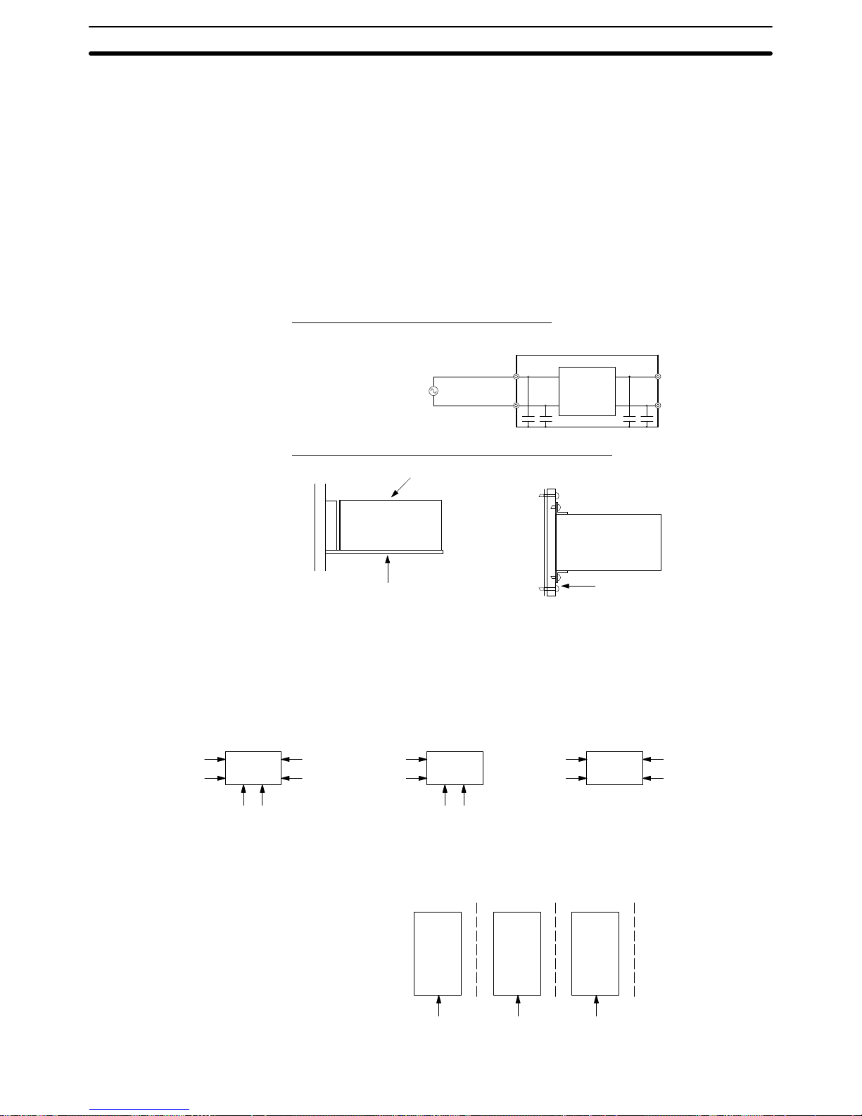
3-7SectionSharing the Same Power Supply
40
3-6 Correcting Faulty Operation Caused by Noise
When noise is thought to be the cause of a malfunction in the DeviceNet network, the following measures may be effective.
Suspend the communications cable shielding wire without grounding it. This will
filter the noise that flows from the ground to the communications cable and will
filter the noise current that flows in the shielding wire.
Suspend the communications power supply without grounding it. This will also
filter the noise that flows from the communications power supply ground to the
communications cable or the noise current that flows in the shielding wire. The
switching power supply is usually connected to the case and the capacitor as
shown below . The FG terminal must be suspended and the control board for the
power supply itself must be insulated.
Switching Power Supply Configuration
Switching power supply
AC power supply AC input
Casing
DC output
Power
supply
circuit
Suspending the Communications Power Supply
S82J power supply
S82Y-jjN (Mounting Tool)
When using S82J power supply
DC power supply
Insulating material (such as
baked board or acrylic board)
When using other power supplies
3-7 Sharing the Same Power Supply
Slave Units in the DeviceNet network can be classified into three types according to how the power is supplied, as shown below. (The DeviceNet Interface Unit
is the middle type.)
I/O power
supply
Communications power
supply
Slave Unit
Internal circuit
power supply
Communications power
supply
Slave Unit
Internal circuit
power supply
Same power
supply for
communications
and internal circuit
Slave Unit
I/O power
supply
Because the power supplies for the communications, internal circuit and I/O are
individually insulated as shown below, as a general rule each power supply
should be connected separately.
Communications
circuit
Insulation
Communications
power supply
Internal
circuit
Insulation
I/O circuit
Insulation
I/O power
supply
Internal circuit
power supply
Communications Cable
Shielding
Communications Power
Supply
Page 56

3-7SectionSharing the Same Power Supply
41
Because of space and cost difficulties involved in preparing individual power
supplies, sharing the same power supply may be unavoidable. If this is the case,
take the following precautions.
• Be sure to keep the I/O power supply separate.
• When the communications and internal circuit power supply is shared, wiring
the network as shown in configuration A is recommended. Do not wire the network as shown in configuration B because it will generate more noise than the
network in configuration A.
Note The lower voltage boundary of the internal circuit power supply must be higher
than that of the communications power supply. To meet the voltage specifications for the internal circuit power supply, be sure to follow the specifications provided in 3-3 Sharing the Communications Power Supply.
Configuration A
Same power supply
for communications
and internal circuit
Communications
power supply
Internal circuit
power supply
V– V+ – +
24VDC
24VDC
V– V+ – +
V– V+ – +
24VDC
V– V+ – +
24VDC
Communications
power supply
Internal circuit
power supply
Communications
power supply
Internal circuit
power supply
Communications
power supply
Internal circuit
power supply
Same power supply
for communications
and internal circuit
Configuration B
Page 57

43
SECTION 4
Installation and Network Connection
This section explains how to mount the DeviceNet Interface Unit on the PT and connect the Unit to the DeviceNet network.
4-1 Components and Their Functions 44. . . . . . . . . . . . . . . . . . . . . . . . . . . . . . . . . . . . . . . . . . . .
4-2 Mounting the Unit on the PT 45. . . . . . . . . . . . . . . . . . . . . . . . . . . . . . . . . . . . . . . . . . . . . . . .
4-3 Connecting to the DeviceNet Network 45. . . . . . . . . . . . . . . . . . . . . . . . . . . . . . . . . . . . . . . .
4-3-1 Connecting Communications Cables 45. . . . . . . . . . . . . . . . . . . . . . . . . . . . . . . . . . .
4-3-2 Installing and Removing the Connector 47. . . . . . . . . . . . . . . . . . . . . . . . . . . . . . . .
4-3-3 Connecting Communications Cables to T-branch Taps 48. . . . . . . . . . . . . . . . . . . . .
4-3-4 Connecting Terminating Resistors 49. . . . . . . . . . . . . . . . . . . . . . . . . . . . . . . . . . . . .
Page 58

4-1SectionComponents and Their Functions
44
4-1 Components and Their Functions
Front view Rear view
Mounting screws
Attach the DeviceNet Interface Unit to the PT.
LED indicators
Indicate the status of the
DeviceNet network and
the I/F Unit.
Communications connector
Connects the Unit to a DeviceNet
network communications cable.
Communications power is also
supplied through this cable.
PT connector
Connects the Unit with the PT.
Note Inspect the DeviceNet Interface Unit for any damage after removing it from its
packaging. Lightly shake the Unit to check whether any parts have broken off
inside.
The following table shows the functions of the LED indicators. The color and status of the MS and NS indicators can be used to troubleshoot errors. Refer to 8-2
Troubleshooting with the LED Indicators for more details.
LED Name Color Status Indicated condition Meaning
MS Module status Green
Lit Normal status Normal Unit condition
Flashing Not set yet Switch settings are being read.
Red
Lit Fatal error Unit hardware error (Watchdog Timer error)
Flashing Non-fatal error Minor error such as incorrect switch settings
--- Not lit No power being supplied • Power is not being supplied to Slave Units.
• Waiting for initialization to start.
• Unit is being reset.
NS Network status Green
Lit Online, communications
established
Normal network condition (communications
established)
Flashing Online, communications
not established
Normal network condition but
communications are not established
Red
Lit Fatal communications
error
Communications error (The Unit detected
an error which makes communications
through the network impossible.)
• Network power supply error
• Node number duplication
• Bus off detected
Flashing Non-fatal
communications error
Communications timeout
--- Not lit Offline or power supply
OFF
• Waiting for completion of the Master’s node
number duplication check
• Incorrect switch settings (such as an incorrect baud rate setting)
• Faulty network communications cable
• Power supply OFF
LED Indicators
Page 59
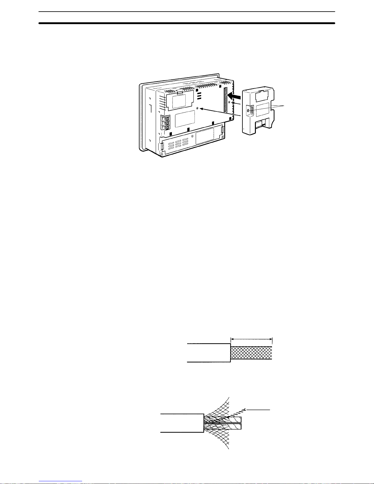
4-3SectionConnecting to the DeviceNet Network
45
4-2 Mounting the Unit on the PT
Mount the DeviceNet Interface Unit to the Expansion Interface Connector on the
back of the PT as shown in the following diagram. (The Expansion Interface
Connector is under the “note” label.) This example shows an NT31/NT31C PT.
Mounting screws
Note 1. Always turn OFF the PT before installing or removing the DeviceNet Inter-
face Unit.
2. Always tighten the two mounting screws after mounting the Unit on the PT.
3. Do not touch the printed circuit board with your bare hands. Discharge the
static electricity from your body before handling the board.
4-3 Connecting to the DeviceNet Network
This manual primarily explains how to connect the DeviceNet Interface Unit to a
DeviceNet network. For details on connecting other Slaves or Masters, refer to
the individual Unit’s manuals.
4-3-1 Connecting Communications Cables
This section explains how to prepare and connect the communications cables to
connectors for the DeviceNet network.
Use the following procedure to prepare and connect the communications cables
to the connectors. Some connectors are equipped with set screws and some are
not; only use connectors with set screws with the DeviceNet Interface Unit.
1, 2, 3... 1. Remove approx. 30 to 80 mm of the cable covering, being careful not to
damage the shield weaving underneath. Do not remove more than about
30 mm; removing too much of the covering can result in short circuits.
Approx. 30 to 80 mm
2. Carefully peel back the weaving. You’ll find the signal lines, power lines, and
the shielding wire. The shielding wire will be loose on the outside of the other
lines, but it is harder than the weaving and should be easily identified.
Shielding wire
Page 60

4-3SectionConnecting to the DeviceNet Network
46
3. Remove the exposed weaving, remove the aluminum tape from the signal
and power lines, and strip the covering from the signal and power lines to the
proper length for the crimp terminal connectors. Twist together the wires of
each of the signal and power lines.
Strip to match the crimp terminals
Note We recommend the following crimp terminals for easier wiring and
improved reliability.
Phoenix Contact K.K., AI-series Crimp Terminals
Crimp
terminal
Wire
Insert the line into the terminal and then crimp.
The following crimp tool is also available.
Phoenix Contact K.K. Contact., ZA3 Crimp Tool
4. Attach the crimp terminals to the lines and then cover any exposed areas of
the cable and lines with electricians tape or heat-shrinking tubes.
5. Orient the connector properly , loosen the line set screws, and then insert the
lines in order from left to right: Black, blue, shield, white, and then red. The
wiring method is the same regardless of whether or not the connector is
equipped with set screws.
Example: T-branch Connection
Blue (CAN low)
Black (–V)
Red (+V)
White (CAN high)
Shield
Note Be sure the wire set screws are sufficiently loosened before attempt-
ing to insert the lines. If these screws are not loose, the lines will enter
the gaps in the back of the connector and will not lock properly.
Bracket
Hole where signal
wire is inserted.
Signal wire
There are colored stickers provided on the Master Unit and Slaves that
match the colors of the lines to be inserted. Be sure that the colors match
when wiring the connectors. These colors are as follows:
Page 61

4-3SectionConnecting to the DeviceNet Network
47
Color Signal
Black Power line, negative voltage (–V)
Blue Communications line, low (CAN low)
--- Shield
White Communications line, high (CAN high)
Red Power line, positive voltage (+V)
6. Tighten the line set screws for each line in the connector. Tighten the screws
to a torque between 0.25 and 0.3 Nm.
Y ou will not be able to tighten these screws with a normal screwdriver , which
narrows to a point at the end. You will need a screwdriver that is consistently
thin for the entire length.
Use a flat-blade screwdriver that is
consistently thin at the end.
The following diagram shows the dimensions of the OMRON XW4Z-00C
screwdriver which is made specifically for tightening these set screws.
Side view Front view
0.6 mm 3.5 mm
4-3-2 Installing and Removing the Connector
Align the cable connector with the Unit connector , insert the cable connector fully, and tighten the screws on both sides of the connector to lock it in place. T ighten the screws to 0.25 to 0.3 N-m.
Note 1. Before connecting the communications cables, turn OFF the power supply
to all PCs, Slaves, and communications power supplies.
Page 62
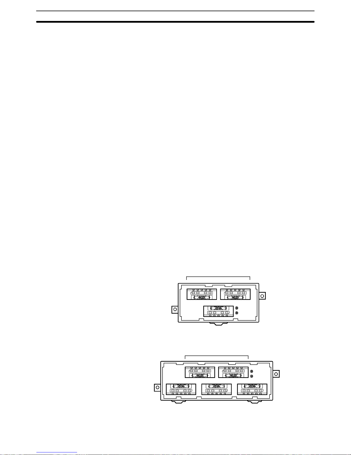
4-3SectionConnecting to the DeviceNet Network
48
2. Use crimp terminals for wiring. Connecting bare twisted wires can cause the
cables to come OFF, break, or short circuit, most likely resulting in incorrect
operation and possibly damage to the Units.
3. Use suitable crimp tools and crimping methods when attaching crimp terminals. Consult the manufacturer of the tools and terminals you are using. Inappropriate tools or methods can result in broken wires.
4. Be extremely careful to wire all signal lines, power lines, and shielding wire
correctly.
5. Tighten all set screws firmly. Tighten to a torque of between 0.25 and
0.3 Nm.
6. Wire the signal lines, power lines, and shielding wire so that they do not become disconnected during communications.
7. Do not pull on communications cables with excessive force.
8. Allow leeway so that communications cables do not have to be bent further
than natural. The Cables may become disconnected or wires may break if
the cables are bent too far.
9. Never place heavy objects on communications cables.
10. Double-check all wiring before turning ON the power supply.
4-3-3 Connecting Communications Cables to T-branch Taps
This section shows how to connect a communications cable with a connector
attached to a T-branch Tap. When using a DeviceNet Interface Unit, we recommend wiring with a T-branch Tap rather than the multi-drop method because it
allows for easier maintenance.
There are two kinds of T -branch Taps, one makes a single branch and the other
makes three branches, but the cable connections are the same for both.
The connectors indicated by asterisks in the following diagrams have the least
resistance and these connectors should be used for the trunk line connections.
When using a T-branch T ap on a drop line, we recommend connecting the longest drop line to these connectors.
DCN1-1C (1 branch)
* Use for trunk line of
longest drop line.
DCN1-3C (3 branches)
* Use for trunk line of
longest drop line.
The required number of connectors is included with the T-branch Taps shown
above. The following table describes the included connectors.
Page 63

4-3SectionConnecting to the DeviceNet Network
49
Model Specifications Manufacturer
XW4B-05C1-H1-D Connector for T-branch Tap connection of a
node (with connector attachment screws)
OMRON
Align the cable connector with the socket on the T-branch Tap as shown in the
following diagram and fully insert the connector into the socket. Tighten the set
screws to secure the connection. T ighten the screws to a torque of between 0.25
and 0.3 Nm.
4-3-4 Connecting Terminating Resistors
Terminating Resistors must be connected at each end of the trunk line. This section shows how to connect the Terminating Resistors.
A terminating resistor is included with the T-branch Tap. Clip the leads on the
resistor to about 3 mm and insert it into the T-branch Tap as shown in the following diagram. The resistor can face in either direction.
A terminating resistor is built into the Terminal-block Terminating Resistor. To
connect the cable to the Terminating Resistor, attach standard M3 crimp terminals to the signal wires and securely screw the terminals to the Terminal-block
Terminating Resistor.
(Unit: mm)
20
40
20
20
Tighten to a torque of 0.3 to 0.5 Nm.
6.0 mm max. 6.0 mm max.
Note To avoid damaging the cable or breaking wires, don’t pull on the cable or bend it
too sharply when connecting it to the terminal block. Also, never put heavy objects on top of the cable.
T-branch Tap Terminating
Resistor
Terminal-block
Terminating Resistor
Page 64

51
SECTION 5
PT Settings and Operations
This section explains the PT settings and operations required to use the DeviceNet Interface Unit.
5-1 Installing the System Program 52. . . . . . . . . . . . . . . . . . . . . . . . . . . . . . . . . . . . . . . . . . . . . . .
5-1-1 PT Operations 52. . . . . . . . . . . . . . . . . . . . . . . . . . . . . . . . . . . . . . . . . . . . . . . . . . . .
5-1-2 Computer Operations 54. . . . . . . . . . . . . . . . . . . . . . . . . . . . . . . . . . . . . . . . . . . . . . .
5-2 Structure of the System Menu 56. . . . . . . . . . . . . . . . . . . . . . . . . . . . . . . . . . . . . . . . . . . . . . .
5-3 Initializing DeviceNet (CompoBus/D) Memory Switches 57. . . . . . . . . . . . . . . . . . . . . . . . .
5-4 Serial Port A Settings 59. . . . . . . . . . . . . . . . . . . . . . . . . . . . . . . . . . . . . . . . . . . . . . . . . . . . . .
5-5 DeviceNet (CompoBus/D) Memory Switch Settings 61. . . . . . . . . . . . . . . . . . . . . . . . . . . . .
5-6 Checking the PT Settings 64. . . . . . . . . . . . . . . . . . . . . . . . . . . . . . . . . . . . . . . . . . . . . . . . . . .
5-7 Checking Communications with the PT 66. . . . . . . . . . . . . . . . . . . . . . . . . . . . . . . . . . . . . . .
5-8 Checking the System Program Version 67. . . . . . . . . . . . . . . . . . . . . . . . . . . . . . . . . . . . . . . .
Page 65

!
5-1SectionInstalling the System Program
52
5-1 Installing the System Program
A special system program must be installed in the PT in order to use the DeviceNet Interface Unit. The system program for the DeviceNet (CompoBus/D) Interface Unit is included with the Unit.
This section explains how to install the system program in the PT. For details on
other operations, refer to the PT’s Setup Manual or the Support Tool’s Operation
Manual. (The NT-series Support Tool must be version 3.2 or higher.)
Reference 1. To install the system program, the system installer software is needed. The
system installer is included with the NT-ZJ3AT1-EV3, ZJCAT1-EV3, and
ZJCAT1-EV4 Support Tool. Install the system installer software when installing the Support Tool in your personal computer. Refer to the Support Tool’s
Operation Manual for details on installing and using the system installer
software.
2. The PT will be completely unusable if the system program is accidentally
erased. Before deleting the system program, confirm that the Support Tool
is equipped with the system installer software and there is a Memory Unit
containing the system program. However, registered screen data and
memory switch settings are retained.
3. Install the system program for the PT being used (NT31, NT31C, NT631, or
NT631C) that supports the DeviceNet Interface Unit.
4. A PT which has the DeviceNet Interface Unit’s system program installed can
use only the functions of a -V1 version of the NT31/NT31C or
NT631/NT631C PT. Only Memory Link communications can be used with
the host. (The actual communications method is specific to the DeviceNet
Interface Unit, but create screen data for the Memory Link method in the
Support Tool.)
5. The computer and PT must be connected in order to transfer the system
program from the computer to the PT. For details, refer to the PT’s Setup
Manual or the Support Tool’s Operation Manual.
5-1-1 PT Operations
To prepare for the system program download, put the PT in system installer
mode and delete the system program from the PT. An NT31/NT31C PT is used
in these examples, but the steps are the same for an NT631/NT631C.
Reference It isn’t possible to download the system program with the DeviceNet Interface
Unit installed. Before downloading the system program for the DeviceNet Interface Unit, remove the DeviceNet Interface Unit from the PT. (The PT must be
OFF when removing the DeviceNet Interface Unit.)
When installing the system program, either turn ON or reset the PT while pressing the touch switch (7.2 mm square) in the upper-left corner of the PT screen.
Turn ON the PT
while pressing here.
Caution Do not turn OFF or reset the PT while data is being transferred.
Putting the PT into
System Installer Mode
Page 66

5-1SectionInstalling the System Program
53
Reference The PT will enter system installer mode automatically when the power is turned
ON if the PT does not contain a system program or contains a corrupted system
program.
In system installer mode, the first screen sets the display language to English or
Japanese. Set the display language to English when using the DeviceNet Interface Unit.
Press English.
The system installer mode’s menu will be displayed.
When the system program is missing or corrupted, the messa g e System program not ex-
ist or incorrect will be displayed.
Press Download System Program.
Press Yes.
The system program will be erased. A message will be displayed while the system program is being erased.
• If Return to Menu is pressed, the PT will return to the system installer mode’s
menu without erasing the system program.
• If the erase operation failed, a screen will be displayed that asks whether or not
to erase the system program again.
When the erase operation is completed, the PT will be ready for the system program to be downloaded.
If the system program was erased properly, the PT will automatically wait for the
system program to be downloaded.
Setting the Display
Language
Erasing the System
Program
Downloading the System
Program
Page 67

5-1SectionInstalling the System Program
54
When the PT is in this status, transfer the system program from the computer’s system installer.
The PT will track the system program transfer
as the program is being downloaded.
If the Abort button is pressed while the PT is downloading or waiting for the
download, the download will be cancelled and a screen will be displayed that
asks whether or not to download the system program again.
5-1-2 Computer Operations
Start the NT-series System Installer in the personal computer and transfer the
system program to the PT.
Extract the system program for the DeviceNet Interface Unit from the floppy disk
that is included with the Unit.
The system programs are in compressed, self-extracting files in two floppy
disks. One disk contains the NT31/NT31C system program (Nt31.exe) and the
other contains the NT631/NT631C system program (Nt631.exe).
Self-extracting file Contents Remarks
Nt31.exe
DRT-E0A.31 System program for the NT31
DRT-E0A.31c System program for the NT31C
Nt631.exe
DRT-E0A.631 System program for the NT631
DRT-E0A.63c System program for the NT631C
The compressed files are self-extracting, so the contents can be extracted just
by double-clicking the file name and specifying the destination directory.
Starting the System Installer
1, 2, 3... 1. Start the system installer by selecting Start/Programs/Omron/Ntst3.2e/
NT-series System Installer from the Windows Start Button. (The menu
names in your system may be slightly different depending upon the Support
Tool version and selections made when the Support Tool was installed.)
2. When the system installer has started, a main menu like the one below will
be displayed.
Any one of the following operations can be used to close the system installer.
Extracting the System
Program
Page 68

5-1SectionInstalling the System Program
55
• Select Download System/Exit from the menu.
• Click the X button in the upper-right corner of the main system installer window.
• Double-click the system installer icon in the upper-left corner of the system in-
staller window.
• Click the system installer icon in the upper-left corner of the main system installer window and select Close from the menu.
• Press the Alt and F4 Keys.
The computer will return to the Windows screen when the system installer
closes.
Use the following procedure to install the system program.
1, 2, 3... 1. Specify the PT Model of the PT in which the system will be installed. The PT
Model field is in the main system installer window.
2. Specify the Drive, File Location (Look in), and System File of the system pro-
gram to be installed. The selected items are displayed in reverse video.
The system programs for the specified PT Model family in the selected
folder will be displayed in the System Files area. Specify the system program to be installed in the PT from this area.
The following table shows the system programs which support the DeviceNet Interface Unit for each PT model.
File name Corresponding PT model
DRT-E0A.31 NT31
DRT-E0A.31c NT31C
DRT-E0A.631 NT631
DRT-E0A.63c NT631C
3. Specify the RS-232C port (COM port) that will be used to communicate with
the PT. The COM port field is in the main system installer window.
4. Click the Go button in the main system installer window.
Installation of the system program will begin. The progress of the transfer
will be tracked during the installation.
5. A message will be displayed when installation is completed. Check the message and click the OK button to confirm.
When installation of the system program is completed, the following display will
appear at the PT allowing the PT to be restarted with the new system program.
Press Run System.
The PT will start regular operation when the system program is started. The system menu will be displayed if screen data has not been transferred.
Reference The PT will be completely unusable if the system program is not downloaded
properly after the PT’s system program is erased. Always download the system
program completely after the system program is erased.
Installing the System
Program
Page 69

5-2SectionStructure of the System Menu
56
5-2 Structure of the System Menu
The System Menu allows the various functions of the PT to be executed using
touch switches displayed as a menu on the touch panel. The structure of the system menu (menu tree) is shown below. The difference between the system program for the DeviceNet Interface Unit and the standard system program is also
shown.
The menu shown here is from an NT31/NT31C PT. The menu items may differ
slightly depending upon the PT model being used, but the items related to the
DeviceNet Interface Unit are the same for all PT models.
This manual explains only the operations that are changed or edited for use with
the DeviceNet Interface Unit. Refer to the PT’s User’s Manual for details on all
other operations.
Quit
Programming Console Function (See note.)
System Version (page 67)
Device Monitor Function
SYSTEM INSTALLER MODE
Exit System Installer
Download System Program (page 53)
Change System Settings
Erase Screen Data
SYSTEM MENU
Quit
Transmit Mode
Maintenance Mode
Expansion Mode
MAINTENANCE
MODE MENU
Quit
Memory Init.
Memory Switch
I/O Settings
Calendar Check
PT Settings (page 64)
Display History
Alarm History
Screen Data Disp.
I/O Check
I/O CHECK MENU
Quit
I/F Check
Device Check
I/F CHECK MENU
Quit
Tool Comm.
Comm. Port A
Comm. Port B
CompoBus/D (page 66)
Printer
DEVICE CHECK MENU
Quit
Buzzer Check
LED Check
LCD Check
Backlight Check
Screen Memory
Touch Switch
Battery
MEMORY INIT. MENU
Quit
Screen Data
Display History
Alarm History
Memory Table
Memory Switch (page 57)
MEMORY
SWITCH MENU
Start-up Wait Time
Key Press Sound
Buzzer Sound
Printer Controller
Print Method
Screen Saver Movement
Screen Saver Start up Time
Hist. Disp. Method
Resume Function
Comm. Auto-return
Time-out Interval
Retry Counts
Comm. A Bar Code (page 59)
Comm. B Select
Comm. B Method
I/O SETTINGS MENU
Quit
Contrast Adjust
Brightness Adjust
DISPLAY HISTORY MENU
Quit
Sort by Occurrence
Sort by Frequency
ALARM HISTORY MENU
Quit
Sort by Occurrence
Sort by Frequency
EXPANSION
MODE MENU
: Operations changed or edited for PT use with the DeviceNet Interface Unit
: Operations deleted for PT use with the DeviceNet Interface Unit
Quit
PT Memory Switch
CompoBus/D Setting Switch
Comm. Speed (page 61)
Self-node No. (page 61)
Strobe ON Time (page 61)
OUT Area Head (page 61)
OUT Area Size (page 61)
IN Area Head (page 61)
IN Area Size (page 61)
Note: Nothing will be executed even if
the Programming Console
Function is selected.
Page 70

Ver 2.10
5-3SectionInitializing DeviceNet (CompoBus/D) Memory Switches
57
5-3 Initializing DeviceNet (CompoBus/D) Memory Switches
In addition to the standard OMRON memory initialization functions, the system
menu for the DeviceNet Interface Unit has a function that initializes CompoBus/D setting switches.
Refer to the PT’s User’s Manual for details on the other memory initialization op-
erations.
Reference 1. Memory initialization cannot be performed when screen memory is write-
protected with the system installer mode’s system settings.
2. Either PT memory switches or CompoBus/D setting switches can be selected from the memory switch initialization menu. Select PT memory
switches to initialize settings other than those for the DeviceNet Interface
Unit.
3. When the CompoBus/D setting switches have been initialized, the DeviceNet Interface Unit will use 32 input words and 32 output words. The number
of words used by all of the Slaves (including the DeviceNet Interface Unit)
must not exceed the maximum number of words available in the Master. In
particular when the Master is a C200HS, a DeviceNet Interface Unit set to its
default settings will use all of the Master’s available words.
If the number of words used by all of the Slaves exceeds the maximum number of words available in the Master, either reduce the number of Slaves or
reduce the number of words used by the DeviceNet Interface Unit by changing the settings of the CompoBus/D setting switches.
The memory switches for the DeviceNet Interface Unit that have been set in the
PT will all be returned to their factory-default settings by the CompoBus/D setting switch initialization function.
Use the following operation in the system menu to initialize all of the memory
switch settings.
Press Maintenance Mode.
Press Memory Init..
Page 71

5-3SectionInitializing DeviceNet (CompoBus/D) Memory Switches
58
Press Memory Switch.
Press CompoBus/D Setting Switch.
Press Yes.
The memory switches for the DeviceNet Interface Unit will be initialized. The message Ini-
tializing will be displayed while initialization is
in progress.
When initialization is completed, a message
will be displayed and then the reset screen will
be displayed.
Press Reset.
The PT will be reset and will restart.
If No is pressed in the CompoBus/D setting switch initialization screen, the
switch settings will not be initialized and the PT will return to the Memory Init.
menu.
The following table shows the default settings that will be set when the CompoBus/D setting switches are initialized.
Item Meaning Setting
Comm. speed Communications speed 125 kbps
Self-node No. Local node number 63
Strobe ON Time Strobe ON time 30
OUT Area Head Output area starting address PM0000
OUT Area Size Output area size 32
IN Area Head Input area starting address PM0032
IN Area Size Input area size 32
Page 72

Ver 2.10
5-4SectionSerial Port A Settings
59
5-4 Serial Port A Settings
When the DeviceNet Interface Unit is used, the PT is connected to the host
through the DeviceNet Interface Unit. That is why the PT cannot communicate
with the host through serial ports A and B. Serial port A can be used only for a bar
code reader and serial port B cannot be used at all.
The NT31/NT31C and NT631/NT631C are equipped with a bar code reader input function that allows character string data to be input from a bar code reader
into character string input fields. This section explains how to set the communications conditions for communications with the bar code reader and the input
data confirmation method.
Reference 1. When a bar code reader is connected to serial port A, character string data
can be input from a bar code reader into character string input fields. The bar
code reader type, connection method, communications settings, and operation are all the same as they are with standard OMRON system programs. This manual does not provide details on these subjects. Refer to the
PT’s Setup Manual for details.
2. Either PT memory switches or CompoBus/D setting switches can be selected from the memory switch menu. The PT memory switches are the
same memory switch settings found in the standard system programs. The
CompoBus/D setting switches are the settings for the DeviceNet Interface
Unit.
3. The system menu for the DeviceNet Interface Unit does not contain settings
for serial port B, so the PT memory switch setting requires only 3 screens.
Use the following operations from the system menu to set the communications
conditions for communications with the bar code reader and the input data confirmation method.
Press Maintenance Mode.
Press Memory Switch.
Page 73

5-4SectionSerial Port A Settings
60
Press PT Memory Switch.
Press the touch switch (next screen) or
touch switch (previous screen) to display the
third memory switch setting screen.
Press Comm. A Bar-Code and then select
ON or None.
The setting option changes each time that the
touch switch is pressed.
When connecting a bar code reader to serial
port A, select ON and then press Set.
Display the required setting for each item by
pressing the touch switches.
The setting option changes each time the
touch switch is pressed.
Page 74

5-5SectionDeviceNet (CompoBus/D) Memory Switch Settings
61
Press Quit.
Pressing “Abort” on the communication condition/confirmation method setting
screen causes the PT to return to the memory switch setting screen (3/3) without
changing the settings. (The previous settings will still be effective).
When the communication condition/confirmation method settings have been
completed, the PT returns to the memory switch setting screen (3/3).
To set other memory switches, select the relevant screen using the
touch
switch (next screen) or
touch switch (previous screen) and then make the set-
ting.
• To confirm the settings and quit the memory switch setting screen, press the
Quit touch switch. The settings made last will be set and the PT will return to
the memory switch menu.
• To quit the memory switch setting screen without confirming the settings, press
the Abort touch switch. The PT will return to the memory switch menu screen
with the previous settings still in effect.
5-5 DeviceNet (CompoBus/D) Memory Switch Settings
The 3 memory switch setting screens are shown in the following diagram.
[ ] (next screen)
[ ] (next screen)
[ ] (previous screen)
[ ] (previous screen)
[ ] (next screen)
[ ] (previous screen)
Screen Layout and
Settings
Page 75

Ver 2.10
5-5SectionDeviceNet (CompoBus/D) Memory Switch Settings
62
Make the following settings in the DeviceNet Interface Unit’s system menu to
use the PT as a Slave in DeviceNet remote I/O communications.
Item Function Settings Default
Comm. Speed Sets the speed used for communications with the
DeviceNet Master.
125, 250, or 500 kbps 125 kbps
Self-node No. Sets the PT’s node number as a DeviceNet Slave. 0 to 63 63
Strobe ON Time Sets the ON time of the strobes that indicate a change in
the PT’s status. The strobes include the screen change
strobe, numeral input strobe, and character string input
strobe. (The strobe ON time is set in ms.)
30 to 100 ms 30
OUT Area Head Sets the leading address of the PT’s output area allocated
in PT memory when used as a DeviceNet Slave.
PM0000 to PM9999 PM0000
OUT Area Size Sets the size of the PT’s output area when used as a
DeviceNet Slave. (The area size is set in words.)
0 to 32 words 32
IN Area Head Sets the leading address of the PT’s input area allocated in
PT memory when used as a DeviceNet Slave.
PM0000 to PM9999 PM0032
IN Area Size Sets the size of the PT’s input area when used as a
DeviceNet Slave. (The area size is set in words.)
0 to 32 words 32
This section only explains how to make these settings. For more details, refer to
6-1 Overview of Remote I/O Communications.
Note Set all of the nodes in the DeviceNet network (Masters and Slaves) to the same
communications speed. Setting a different communications speed in a Slave
won’t only disable communications with that Slave, it can also cause communications errors between nodes that are set to the correct communications
speed.
Reference 1. If the node number setting is identical to the node number set on another
node in the network, a node number duplication error will occur and the PT
won’t participate in network communications.
2. Always set the strobe ON time longer than the instruction-execution cycle
time of the PC in which the Master is mounted. If the strobe ON time is shorter than the Master PC’s cycle time, the Master PC may not recognize the
strobe signal.
3. If possible, include the PT status notify area within the input area.
4. If possible, include the PT status control area within the output area.
5. The settings for the output area size and input area size determine the sizes
of the PT’s output area and input area when it is used as a Slave.
Use the following operation in the system menu to set the CompoBus/D memory
switches.
Press Maintenance Mode.
Making Settings
Page 76

5-5SectionDeviceNet (CompoBus/D) Memory Switch Settings
63
Press Memory Switch.
Press CompoBus/D Setting Switch.
Press the touch switch (next screen) or
touch switch (previous screen) to display the
desired CompoBus/D switch setting screen.
The current settings will be displayed when
the desired screen is selected.
The setting option changes each time the
touch switch is pressed.
Press Quit when the CompoBus/D switch set-
tings have been completed.
The final settings will go into effect and the reset screen will be displayed.
Press Reset. The PT will be reset and the PT
will restart.
To set other memory switches, select the relevant screen using the
touch
switch (next screen) or touch switch (previous screen) and then make the setting.
Page 77

5-6SectionChecking the PT Settings
64
To quit the CompoBus/D switch setting screen without confirming the settings,
press the Abort touch switch. The PT will return to the memory switch menu
screen with the previous settings still in effect.
5-6 Checking the PT Settings
This section explains how to check the settings for direct access of the PT’s
screen data, bar code reader settings for serial port A, and the DeviceNet Interface Unit’s settings.
The 3 PT setting status screens are shown in the following diagram.
[ ] (next screen)
[ ] (next screen)
[ ] (previous screen)
[ ] (previous screen)
[ ] (next screen)
[ ] (previous screen)
The third screen in the DeviceNet Interface Unit’s system menu shows the CompoBus/D switch settings.
Contents of Screen 1/3
It is possible to check the contents of the PT configuration settings set in screen
data with the Support Tool. For details on Support Tool settings when using the
DeviceNet Interface Unit, refer to 6-2 Settings with the NT-series Support Tool.
Item Meaning Name in Support
Tool
Screen Data Type The PC model set for the screen
data. (Always Memory Link)
PLC Vendor in PT
Type
PT Control Area Shows the words in the host (PT
memory words) allocated to the PT
status control area. PT memory is
displayed as “PM.”
Control/Notify Area
PT Notification Area Shows the words in the host (PT
memory words) allocated to the PT
status notify area. PT memory is
displayed as “PM.”
Window Control Area Shows the words in the host (PT
memory words) allocated to the
window control area. PT memory is
displayed as “PM.”
Numeric Expression Shows the default format for the
contents of words in the host that
are allocated to numeral memory
tables.
Numeral Storage
Type in System
When the DeviceNet Interface Unit is used, the PT status control area contains 5
words, the PT status notify area contains 3 words, and the window control area
contains 9 words. (In the standard OMRON configuration, the PT status notify
area contains 2 words.)
The “Expansion I/F” setting is not displayed in the system menu for the DeviceNet Interface Unit.
Contents of Screen 2/3
Item Meaning
Bar Code Reader Shows whether a bar code reader is used at serial port A.
Screen Layout and
Settings
Page 78

Ver 2.10
5-6SectionChecking the PT Settings
65
Contents of Screen 3/3
Item Meaning
Connection Status Shows whether or not the DeviceNet Interface Unit is
installed.
Comm. Speed Communications speed in the DeviceNet network
OUT Area Shows the DeviceNet output area words allocated in PT
memory.
IN Area Shows the DeviceNet input area words allocated in PT
memory.
Local Node No. Shows the PT’s node number as a DeviceNet Slave.
Use the following operation in the system menu to display the PT settings.
Press Maintenance Mode.
Press PT Settings.
Press the touch switch (next screen) or
touch switch (previous screen) to display the
desired screen.
Press Quit to return to the maintenance mode
menu.
Displaying Settings
Page 79

Ver 2.10
5-7SectionChecking Communications with the PT
66
5-7 Checking Communications with the PT
Use the following operation in the system menu to check communications between the PT and the DeviceNet Interface Unit.
Press Maintenance Mode.
Press I/O Check.
Press I/F Check.
Press CompoBus/D.
The CompoBus/D Communications Check
screen will be displayed.
Page 80

Ver 3.10
5-8SectionChecking the System Program Version
67
The communications check begins when Execute is pressed in the CompoBus/D Communications Check screen. The data string “01 02 04 08 10 2 0 4 0 80 ”
is sent to the DeviceNet Interface Unit and displayed under Sending Data.
If communications with the Unit are normal, the same data “01 02 04 08 10 20 40
80” will be displayed under Received Data.
If an error occurs in communications with the Unit during the check, the correct
data will not be displayed under Received Data or a communications error
screen will be displayed. Check the PT’s settings if a communications error oc-
curs.
After checking the results of the communications check, press Quit to return to
the I/F check menu.
5-8 Checking the System Program Version
The version of the system program installed in the PT can be displayed.
Reference Refer to 5-1 Installing the System Program for details on installing the system
program that supports the DeviceNet Interface Unit.
Use the following operation in the system menu to display the PT system pro-
gram’s version information.
Press Expansion Mode.
Press System Version.
Page 81

5-8SectionChecking the System Program Version
68
The PT model, system program name, system
program version, and creation date will be displayed.
After checking the system program information, press Quit to return to the ex-
pansion mode menu.
Page 82

69
SECTION 6
Remote I/O Communications
This section shows how to use remote I/O communications with the DeviceNet Interface Unit and how to use the PT when
using remote I/O communications.
6-1 Overview of Remote I/O Communications 70. . . . . . . . . . . . . . . . . . . . . . . . . . . . . . . . . . . . .
6-1-1 Data Exchange with the DeviceNet Interface Unit 70. . . . . . . . . . . . . . . . . . . . . . . .
6-2 Settings with the NT-series Support Tool 72. . . . . . . . . . . . . . . . . . . . . . . . . . . . . . . . . . . . . . .
6-2-1 Setting the PT Model and PC Model 72. . . . . . . . . . . . . . . . . . . . . . . . . . . . . . . . . . .
6-2-2 Allocating Required Areas and Elements in PT Memory 72. . . . . . . . . . . . . . . . . . .
6-2-3 Allocation Example 74. . . . . . . . . . . . . . . . . . . . . . . . . . . . . . . . . . . . . . . . . . . . . . . .
6-3 Allocating PT Memory to the Host (Master) 74. . . . . . . . . . . . . . . . . . . . . . . . . . . . . . . . . . . .
6-3-1 Allocating Input and Output Areas to PT Memory 74. . . . . . . . . . . . . . . . . . . . . . . .
6-3-2 Allocating Input and Output Areas to the Master 76. . . . . . . . . . . . . . . . . . . . . . . . .
6-4 Allocating PT Data to PT Memory 81. . . . . . . . . . . . . . . . . . . . . . . . . . . . . . . . . . . . . . . . . . .
6-4-1 Precautions when Allocating Data to PT Memory 81. . . . . . . . . . . . . . . . . . . . . . . .
Page 83

6-1SectionOverview of Remote I/O Communications
70
6-1 Overview of Remote I/O Communications
The Master and Slaves can communicate as described below with DeviceNet
remote I/O communications.
• Input Area:
Inputs at the Slave are read automatically and mirrored in the Master’s input
area.
• Output Area:
Data written in the output area allocated in the Master’s memory are automatically output to the corresponding Slave.
Reference The names of the input and output areas indicate the direction of I/O from the
perspective of the Master (host).
6-1-1 Data Exchange with the DeviceNet Interface Unit
The DeviceNet Interface Unit using remote I/O communications can exchange
data with the host to control the PT or check its status.
The three allocation settings listed below must be made in order to perform remote I/O communications between the Master (PC) and PT using the DeviceNet
Interface Unit.
1, 2, 3... 1. The settings that allocate PT data (the PT status control/notify areas, win-
dow control area, or other elements) to PT memory
Allocated data Allocation method
PT status control area, PT status notify
area, and window control area
Set the Control/Notify Area in the
NT-series Support Tool’s PT
Configuration settings.
Other
eleme
Numeral, character string, and
bit memory table data
Set in the NT-series Support Tool’s
Table settings.
nts
Lamps and touch switches Set in each element’s properties
with the NT-series Support Tool.
The allocation settings above are the same as they are with a regular PT set
for Memory Link method.
2. The settings that allocate the DeviceNet Interface Unit’s input and output
areas in PT memory within the PT
Set the input and output areas with the CompoBus/D setting switches in the
PT’s system menu. (Other DeviceNet memory switch settings are also required. Refer to 5-5 DeviceNet Memory Switch Settings for details.)
3. The settings that allocate the DeviceNet Interface Unit’s input and output
areas in the I/O memory of the Master (PC) (Free allocation or fixed allocation can be used.)
Page 84
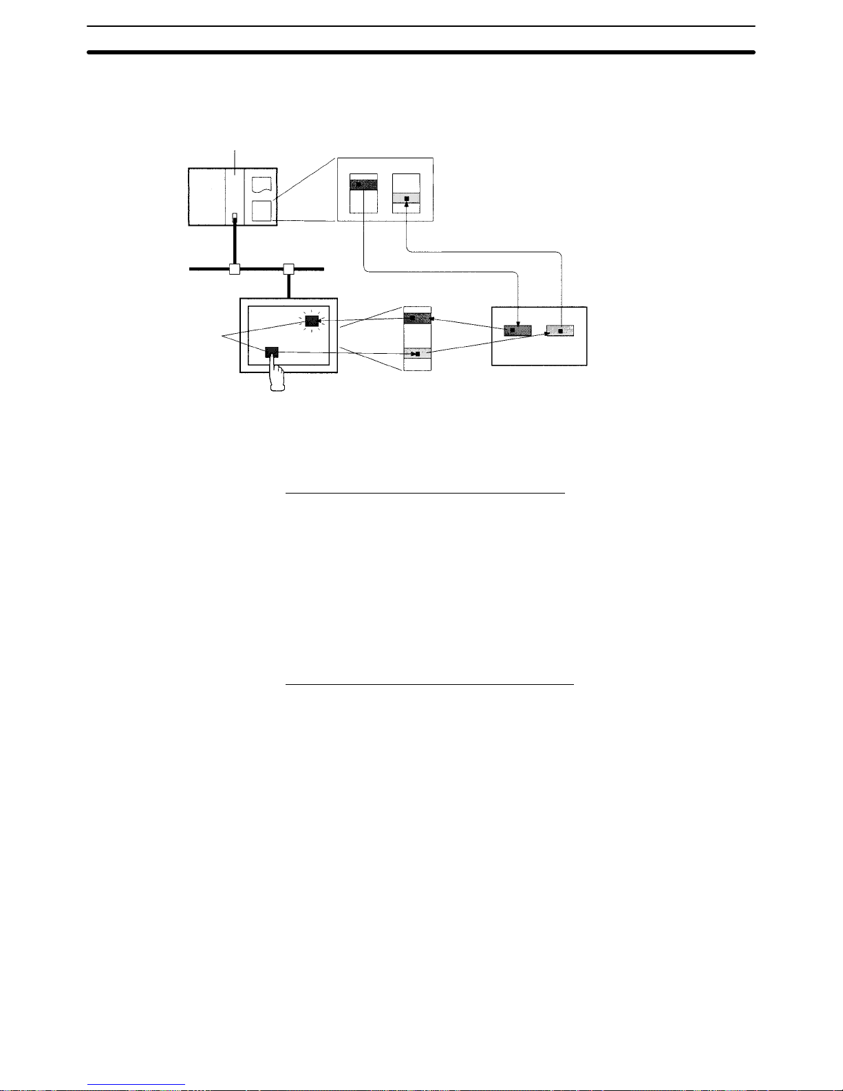
6-1SectionOverview of Remote I/O Communications
71
Set the input and output areas with the DeviceNet Master Unit’s software
switches or the Configurator.
Master Unit
PC
I/O memory
Allocation
3
Allocation
2
Allocation
1
Automatic I/O
PT memory
within PT
The DeviceNet Interface Unit’s input
and output areas are allocated in the
Master’s I/O memory (work area etc.).
I/O data is transferred automatically so
that the contents are the same.
The DeviceNet Interface Unit’s output area is regularly written to the
area allocated in PT memory and
the contents of the input area are
regularly read.
DeviceNet Interface Unit
Output
area
Input
area
PT
Elements
Elements in the PT’s screen are
directly accessed using the PT
memory within the PT.
Output area Input area
Reading PT Status (Input Area Operations)
1, 2, 3... 1. If changes are made to the status or memory tables by PT or other opera-
tions, the changes are mirrored in PT memory.
2. If there are changes in PT memory, the contents are automatically mirrored
in the corresponding input area.
3. The contents of the DeviceNet Interface Unit’s input area are mirrored in the
part of the host’s input area that is allocated to the DeviceNet Interface Unit.
4. The changes in PT status or memory tables can be read from the contents of
the host’s input area.
Controlling the PT (Output Area Operations)
1, 2, 3... 1. Write data in the part of the host’s output area that is allocated to the Device-
Net Interface Unit.
2. Data written to the host’s output area is automatically mirrored in the DeviceNet Interface Unit’s output area.
3. Data in the DeviceNet Interface Unit’s output area is automatically written to
the corresponding part of PT memory.
4. The PT’s display and operation change in accordance with the contents of
PT memory.
The strobe ON time is the length of time that the PT keeps ON the signals which
notify the host (Master) of a change in PT status. The strobe ON time setting controls all three strobes (the screen-switching strobe, numeral-input strobe, and
character-string-input strobe.) Set the strobe ON time with the PT system
menu’s CompoBus/D setting switch.
Each strobe signal is turned OFF automatically after the strobe ON time elapses.
When setting the strobe ON time, be sure that it is longer than the cycle time in
the host’s CPU Unit so that the host (Master) will reliably read changes in the
Precautions for the
Strobe ON Time Setting
Page 85

6-2SectionSettings with the NT-series Support Tool
72
strobe status. If the strobe ON time is shorter than the CPU Unit’s cycle time, the
Master may not read changes in the PT’s status properly.
Strobe signal
(PT → Master)
Strobe ON time
(30 to 100 ms)
6-2 Settings with the NT-series Support Tool
This section explains the settings required at the Support Tool when using a PT
with a DeviceNet Interface Unit installed. Refer to the PT’s manuals for details on
other settings required to use the PT. Refer to the Support Tool’s Operation
Manual for details on basic Support Tool operations.
6-2-1 Setting the PT Model and PC Model
The PT model and PC model must be set as follows at the PT to which the DeviceNet Interface Unit is installed.
PT Model: For an NT31: NT31-V1 (System Ver.2.1)
For an NT31C: NT31C-V1 (System Ver.2.1)
For an NT631: NT631-V1 (System Ver.2.1)
For an NT631C: NT631C-V1 (System Ver.2.1)
PC Model (PLC Vendor): MEMLINK (Memory Link)
Set the PT model and PC model (PLC Vendor) in the PT Type Tab of the Support
Tool’s PT Configuration Dialog.
6-2-2 Allocating Required Areas and Elements in PT Memory
In order to use the PT, the PT status control/notify areas, memory tables, and
elements must be allocated in the host’s area (called PT memory when using the
Memory Link.)
When using the DeviceNet Interface Unit to communicate with the host (Master),
it is necessary to plan the allocation of the input and output areas in PT memory
at the same time that you decide on the allocation of the PT status control/notify
areas, memory tables, and elements.
Reference 1. The input and output areas are regularly accessed from the host by remote
I/O communications, so allocate areas and elements that are refreshed frequently. The input area is only read from the host and the output area is only
written from the host.
Parts of PT memory outside of the input and output areas are accessed by
explicit messages sent by the host, so it is best to allocate areas and data
that aren’t changed often. On the other hand, this area can be used for twoway read/write access from the host, so consider allocating parts of PT
memory outside of the input and output areas to frequently refreshed data if
two-way data transfer is required.
Refer to 6-3 Allocating PT Memory to the Host (Master) for details on allocat-
ing PT memory for the input and output areas.
2. Since the input and output areas are allocated in the PT’s system menu, the
allocation is not checked from the Support Tool. There is no check to prevent
the output area that is written from the host from being allocated as an area
that is written from the PT.
Page 86

6-2SectionSettings with the NT-series Support Tool
73
The following three control and notify areas must be allocated in PT memory in
order for the PT to be used.
• PT status control area (5 words)
• PT status notify area (3 words)
• Window control area (9 words)
(It isn’t necessary to allocate these words when the PT’s window functions
aren’t being used.)
Allocate the control/notify areas in the Control/Notify Area Tab of the Support
Tool’s PT Configuration dialog. Set the leading PT memory address being allocated to each area in the PC address setting columns.
Reference 1. Data in the PT status control area and PT status notify area has to be ex-
changed frequently with the host (Master), so allocate these areas to the
DeviceNet Interface Unit’s output and input areas as shown below if at all
possible.
• PT status control area: In the DeviceNet Interface Unit’s output area
• PT status notify area: In the DeviceNet Interface Unit’s input area
2. When the DeviceNet Interface Unit is being used, the first word of the PT
status notify area indicates the screen number of the screen currently being
displayed at the PT. For this reason, the PT status notify area requires one
word more than it does with the regular Memory Link.
3. The control/notify area settings registered in the PT can be displayed with
the PT Settings screen from the PT’s system menu. Refer to 5-6 Checking
the PT Settings for details.
Allocate elements such as memory tables, lamps, or touch switches in PT
memory when displaying the contents of host (Master) words on the PT screen
or notifying the host (Master) of the results of PT operations.
Make allocation settings for numeral memory tables, character string memory
tables, and bit memory tables with the Support Tool’s Table screen. Make allocation settings for each element in each element’s properties.
Data in the input and output areas is transferred in only one direction, so be sure
to allocate data based on its usage, i.e., whether it is being transferred from
PT → Host, Host → PT, or PT↔ Host.
It is important to consider the direction of data flow (PT → Host, Host → PT, or
PT ↔ Host) and number of words required when allocating the PT’s control/
notify areas, memory tables, and data such as elements to the output and input
areas. Use the following table for reference.
Area or data type Allocation size
Allocation to input or output area
Input area
(PT → Host)
Output area
(Host → PT)
PT status control area 5 words, fixed × n
PT status notify area 3 words, fixed
f
×
Window control area 9 words, fixed n n
Numeral memory table 1 or 2 words
(See note 1.)
n n
Character string memory
table
1 to 20 words
(See note 1.)
n n
Bit memory table 1 bit ×
f
Lamp (lamp bit) 1 bit ×
f
Touch
Notification bit 1 bit
f
×
switch
Lamp bit 1 bit ×
f
f: Allocation OK
n: The functions are limited to the allocated area’s transfer direction.
×: Allocation not possible
Allocating Control/Notify
Areas
Allocating Data
Area/Data Type and
Output/Input Area
Allocation
Page 87

6-3SectionAllocating PT Memory to the Host (Master)
74
Reference 1. The number of words allocated to the memory tables can be set with the
Support Tool.
2. The output area and input area can be allocated up to 32 words of PT
memory each. Refer to 6-3 Allocating PT Memory to the Host (Master) for
details.
6-2-3 Allocation Example
Elements allocated in PT memory:
Element Allocation
PT status control area 1 (Fixed at 5 words)
PT status notify area 1 (Fixed at 2 words)
Lamps 2
Touch switches (input notification function) 3
Numeral memory tables 0 to 3 4 (1 word each)
Address PT memory
PT status notify area
Output area
(Host → PT)
Lamps
Touch switches
(Lamp bits)
Input area
(PT → Host)
Touch switches
(Notification bits)
PT status control area
Lamps and touch switches
Numeral memory table 0
Numeral memory table 1
Touch switches
Numeral memory table 2
Numeral memory table 3
15 14 13 1211 10 9 8 7 6 5 4 3 2 1 0 Bit
15 14 13 1211 10 9 8 7 6 5 4 3 2 1 0 Bit
PM0000
to
PM0004
PM0005
PM0006
PM0007
PM0008
to
PM0031
PM0032
to
PM0034
PM0035
PM0036
PM0037
PM0038
to
PM0063
PM0064
to
6-3 Allocating PT Memory to the Host (Master)
In order to use remote I/O communications with the DeviceNet Interface Unit, PT
memory must be allocated in the host’s DeviceNet I/O memory (input and output
areas).
The following two steps are required to allocate PT memory in the host’s input
and output areas.
• Allocate the DeviceNet Interface Unit’s input and output areas in the PT’s inter-
nal PT memory. (Allocate memory with the PT’s system menu.)
• Allocate the DeviceNet Interface Unit’s input and output areas in the I/O
memory of the PC (CPU Unit) where the Master is mounted. (Allocate memory
to the Master as a DeviceNet Slave.)
The steps above indirectly allocate part of the PT memory’s area to the host’s
(Master’s) I/O memory as input and output areas.
6-3-1 Allocating Input and Output Areas to PT Memory
PT memory consists of 10,000 words from 0000 to 9999 (PM0000 to PM9999).
The DeviceNet Interface Unit’s input and output areas can be allocated to any
location in PT memory and each area can be up to 32 words long.
Page 88

6-3SectionAllocating PT Memory to the Host (Master)
75
Allocate input and output areas to PT memory from the PT’s system menu by
selecting CompoBus/D Setting Switches.
Item Function Setting range Default
Output area leading
address
Sets the leading PT memory address of the PT’s output
area when the PT is used as a DeviceNet Slave.
PM0000 to PM9999 PM0000
Output area size Sets the size of the PT’s output area when the PT is
used as a DeviceNet Slave.
(The area size is set in words.)
0 to 32 words 32
Input area leading
address
Sets the leading PT memory address of the PT’s input
area when the PT is used as a DeviceNet Slave.
PM0000 to PM9999 PM0032
Input area size Sets the size of the PT’s input area when the PT is used
as a DeviceNet Slave.
(The area size is set in words.)
0 to 32 words 32
PT
PT memory
Output area leading address
(PM0000 to PM9999)
Output area size
(0 to 32 words)
Input area leading address
(PM0000 to PM9999)
Input area size
(0 to 32 words)
DeviceNet Interface Unit
Output area Input area
Allocate settings in the CompoBus/D setting
switches screen of the PT’s system menu.
Refer to 5-5 DeviceNet Memory Switch Settings for details on making settings in
the CompoBus/D setting switches screen of the PT’s system menu.
Reference The output area settings are in the second page of the CompoBus/D setting
switches screen and the input area settings are in the third page.
Page 89

6-3SectionAllocating PT Memory to the Host (Master)
76
6-3-2 Allocating Input and Output Areas to the Master
The DeviceNet Interface Unit’s input and output areas are allocated to the Unit
as a DeviceNet Slave in the Master’s I/O memory.
With fixed allocation, words in the CPU Unit are allocated in the order of node
numbers starting from node 00. The words are divided into an output area and
an input area. The specific words that are allocated depend on the model of PC
that is being used.
CIO 1900
CIO 1963
CIO 2000
CIO 2063
Output
area
Input
area
CIO 1900 Node 0
CIO 1901 Node 1
CIO 1962 Node 62
CIO 1963 Node 63
CIO 2000 Node 0
CIO 2001 Node 1
CIO 2064 Node 62
CIO 2063 Node 63
IR 50
IR 81
IR 350
IR 381
Output
area
Input
area
IR 50 Node 0
IR 51 Node 1
IR 80 Node 30
IR 81 Node 31
IR 350 Node 0
IR 351 Node 1
IR 380 Node 30
IR 381 Node 31
To Slaves
From Slaves
To Slaves
From Slaves
IR 50
IR 99
IR 350
IR 399
Output
area
Input
area
IR 50 Node 0
IR 51 Node 1
IR 98 Node 48
IR 99 Node 49
IR 350 Node 0
IR 351 Node 1
IR 398 Node 48
IR 399 Node 49
To Slaves
From Slaves
CVM1/CV-series PCs
CS1-series PCs
C200HS PCs
IR 50
IR 99
IR 350
IR 399
Output
area
Input
area
IR 50 Node 0
IR 51 Node 1
IR 98 Node 48
IR 99 Node 49
IR 350 Node 0
IR 351 Node 1
IR 398 Node 48
IR 399 Node 49
To Slaves
From Slaves
C200HX/HG/HE PCs
The DeviceNet Interface Unit will occupy the number of words (number of node
numbers) set for the input and output areas in the DeviceNet memory switch
screen. For example, when the Unit’s input area size has been set to 16 words,
the output area size has been set to 10 words, and the node number is set to 5,
the input area will occupy the words for nodes 5 through 20 and the output area
will occupy the words for nodes 5 through 14.
Note With the CS1 Series, the DeviceNet Output Area (CIO 0050 to CIO 0099) is con-
tained inside the I/O Area (CIO 0000 to CIO 0319). For this reason, in systems
with a large number of I/O points, edit the I/O table with the CX-programmer so
that there is no overlap of area allocation.
Each node address is allocated one input and one output word. If a Slave requires more than one input or one output word, then it is assigned more than one
node address. If a Slave requires less than one word, it simply uses the rightmost bits in the word allocated to it.
Fixed Allocation
Page 90
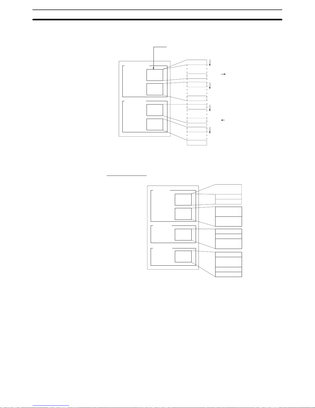
6-3SectionAllocating PT Memory to the Host (Master)
77
A Configurator can be used to allocate a total of 4 blocks” blocks 1 and 2 in the
output area and input blocks 1 and 2 in the input area in any order.
CPU Unit
Output
block 1
Output
block 2
Input
block 1
Input
block 2
Blocks can be positioned in any order in memory,
e.g., the following order is okay: input block 1, output
block 2, input block 2, output block 1.
Address
Address
Address
Address
Address
Address
Address
Address
To Slaves
From Slaves
Addresses can be assigned
in any order
Output area
Input area
Slaves and blocks can be allocated in any order . The number of words (number
of bytes) that are used depends upon the addresses. The minimum is one byte
and the maximum is 64 bytes (32 words).
Setting Example
CPU Unit
Output
block 1
Input
block 2
Output
block 2
Address 5
IR Area
HR Area
Address 14
Address 3
Address 8
Address 10
Address 1
Address 6
Address 9
DM Area
Address 3
Address 11
Address 6
Address 7
Input
block 1
User-set (Free) Allocation
Page 91

6-3SectionAllocating PT Memory to the Host (Master)
78
Data Areas for Remote I/O Communications
Item Master model Fixed Allocation
(Without Configurator)
Free Allocation
(With Configurator)
Maximum number of
CVM1/CV-series 63 nodes
Slaves per Master
CS1-series,
C200HX/HG/HE
50 nodes 63 nodes
C200HS 32 nodes 63 nodes
Maximum number of
controlled I/O points
CVM1/CV-series 2,048 points (64 input words and
64 output words)
6,400 points (100 words × 4 blocks)
per Master
CS1-series,
C200HX/HG/HE
1,600 points (50 input words and
50 output words)
4,800 points (without messaging)
1,600 points (with messaging)
C200HS 1,024 points (32 input words and
32 output words)
1,280 points
Maximum number of
CVM1/CV-series
32 input words and 32 output words
I/O points in Slave
controlled by Master
CS1-series,
C200HX/HG/HE
C200HS
Remote I/O allocation
area
CVM1/CV-series Input: CIO 2000 to CIO 2063
Output: CIO 1900 to CIO 1963
CV500/CVM1-CPU01 (-Vj)
CIO: 0000 to 2427
G: G008 to G255
DM: D00000 to D08191
Other PCs:
CIO: 0000 to 2555
G: G008 to G255
DM: D00000 to D24575
CS1-series,
C200HX/HG/HE
CS1-series PCs:
Input: CIO 0350 to CIO 0399
Output: CIO 0050 to CIO 0099
C200HX/HG/HE:
Input: IR 350 to IR 399
Output: IR 50 to IR 99
CS1-series PCs
CIO: 0000 to 0235, 0300 to 0511
HR: HR000 to HR099
CIO: 1000 to 1063 (see note)
DM: D00000 to D05999
C200HE-CPU11(-Z)
IR: 0000 to 0235, 0300 to 0511
HR: HR000 to HR099
LR: LR00 to LR63
DM: DM0000 to DM4095
Other C200HX/HG/HE PCs
IR: 0000 to 0235, 0300 to 0511
HR: HR000 to HR099
LR: LR00 to LR63
DM: DM0000 to DM5999
C200HS Input: IR 350 to IR 381
Output: IR 50 to IR 81
IR: 0000 to 0235, 0300 to 0511
HR: HR000 to HR099
LR: LR00 to LR63
DM: D00000 to D05999
Note When LR 00 t o L R 6 3 are allocated in CS1-series PCs with the Configurator, the
actual words allocated are CIO 1000 to CIO 1063.
When free (user-set) allocation is used, up to 4 blocks (2 output blocks and 2
input blocks of up to 100 words each) can be set in the areas listed in the table
above.
Reference There are limits on free allocation in CS1-series PCs. Follow the limits shown in
the table above.
This section explains how to connect the DeviceNet network properly.
Reference Only the basic connection procedures are explained here. Refer to the Device-
Net (CompoBus/D) Operation Manual (W267) for more details.
Registering the Remote
I/O Allocation Area
Page 92

6-3SectionAllocating PT Memory to the Host (Master)
79
Fixed Allocation
The Master Unit’s software settings for the following example procedure are
shown below.
PC model Leading word address
CVM1/CV-series CIO 1500 + (25 × unit number)
CS1-series CIO 2000 + (10 × unit number)
C200HX/HG/HE with unit numbers 0 to 9 IR 100 + (10 × unit number)
C200HX/HG/HE with unit numbers A to F IR 400 + (10 × (unit number – 10))
Not used.
Bit
Scan list enable bit
Scan list clear bit
Communications error stop release bit
Start remote I/O communications bit
Stop remote I/O communications bit
15 14 13 12 11 10 9 8 7 6 5 4 3 2 1 0
Use the following procedure to register the remote I/O allocation area.
1, 2, 3... 1. Turn ON the Master (PC) after making any required Master Unit hardware
settings. Refer to the DeviceNet (CompoBus/D) Operation Manual (W267)
for details on Master Unit hardware settings.
2. Connect a Programming Device to the PC, turn ON the Master (PC), and
create the I/O table.
3. Turn OFF the Master (PC).
4. Turn ON all of the Slaves connected to the Master.
Make the required settings in the CompoBus/D memory switch screen of the
PT connected to the CompoBus/D Interface Unit and reset the PT. Always
set the input area size and output area size first.
5. Turn ON the Master (PC).
6. Switch the Master (PC) to PROGRAM mode.
7. Check the Master’s “Registered Slave information area” and verify that
communications have been established with the connected Slaves. The
location of the “Registered Slave information area” depends upon the PC
being used as shown below.
PC model Leading word address + 2
CVM1/CV-series CIO 1502 + (25 × unit number)
CS1-series CIO 2002 + (10 × unit number)
C200HX/HG/HE with unit numbers 0 to 9 IR 102 + (10 × unit number)
C200HX/HG/HE with unit numbers A to F IR 402 + (10 × (unit number – 10))
Leading address + 2
Leading address + 3
Leading address + 4
Leading address + 5
Bit
15 14 13 12 11 10 9 8 7 6 5 4 3 2 1 0
The numbers in the table above indicate the node numbers corresponding
to each bit. A Slave is communicating normally when the bit corresponding
to its node number is ON.
8. Use a PC Programming Device to turn bit 01 of the software switches (the
scan list clear bit) from OFF to ON. (This operation is disabled when the
Master is operating in scan list disabled mode.)
Page 93

6-3SectionAllocating PT Memory to the Host (Master)
80
After a short time, turn the scan list clear bit OFF again. We recommend
turning the bit OFF after verifying the results of the operation in the master
status area.
9. Use a PC Programming Device to turn bit 00 of the software switches (the
scan list enable bit) from OFF to ON.
After a short time, turn the scan list enable bit OFF again. We recommend
turning the bit OFF after verifying the results of the operation in the master
status area.
If the remote I/O allocation was registered properly and the Master is operating in scan list enabled mode, the dot display on the Master Unit’s 7-segment LED will be OFF and remote I/O communications will start with the registered allocation.
Use a PC Programming Device to check whether remote I/O communications are operating as expected.
When the remote I/O allocation has been performed properly, remote I/O
communications will start automatically the next time that the Master starts.
Free (User–set) Allocation
Use the following procedure to register the remote I/O allocation area.
This example provides a summary of the relevant Configurator operations. Re-
fer to the DeviceNet (CompoBus/D) Configurator Operation Manual (W328) for
more details.
Reference This example explains the allocation when there is only one Master . Refer to the
DeviceNet (CompoBus/D) Operation Manual (W267) for details on allocation
with more than one Master.
1, 2, 3... 1. Turn ON the Master (PC) after making any required Master Unit hardware
settings. Refer to the DeviceNet (CompoBus/D) Operation Manual (W267)
for details on Master Unit hardware settings.
2. Connect a Programming Device to the PC, turn ON the Master (PC), and
create the I/O table.
3. Turn OFF the Master (PC).
4. Connect the Configurator to the DeviceNet network.
5. Turn ON all of the Slaves.
Make the required settings in the DeviceNet memory switch screen of the
PT connected to the DeviceNet Interface Unit and reset the PT. Always set
the input area size and output area size first.
6. Put the Configurator in online mode and read the network configuration.
7. Create the Mater parameters. The Master parameters contain the input and
output area settings and Slave I/O allocation. Always save the Master parameters in a file.
8. Turn OFF all of the Slaves.
9. Turn ON the Master (PC).
10. Read the network configuration with the Configurator.
1 1. Switch to the Master Unit’s device parameters editing page in the Configura-
tor, read the Master parameter file created in step 7., and write those Master
parameters to the Master Unit.
12. Turn ON all of the Slaves.
13. Start remote I/O communications with the Configurator.
Use a PC Programming Device to check whether remote I/O communications are operating as expected.
When the remote I/O allocation has been performed properly, remote I/O
communications will start automatically the next time that the Master starts.
Page 94

6-4SectionAllocating PT Data to PT Memory
81
If remote I/O communications are operating properly, we recommend reading the network configuration with the Configurator and saving that configuration as a file for future reference.
6-4 Allocating PT Data to PT Memory
The following data can be allocated in PT memory.
• PT status control area (5 words, fixed)
• PT status notify area (3 words, fixed)
• Window control area (9 words, fixed)
• Numeral memory table (1 or 2 words)
• Character string memory table (1 to 20 words)
• Bit memory table (1 bit)
• Lamp (1 bit)
• Touch switch (1 bit, and another bit for the host notification function)
Reference 1. The DeviceNet Interface Unit can be mounted to an NT31, NT31C, NT631,
or NT631C PT. A PT with the DeviceNet Interface Unit’s system program
installed can use only the -V1 version functions of the PT.
2. Refer to the NT31/NT631 Programmable Terminal Reference Manual
(V064) for details on PT screen elements and functions.
Use the NT-series Support Tool for Windows (version 3.2 or higher) for operations such as creating screens displayed on the PT, registering screen elements,
and allocating PT memory.
The procedures for creating screens are the same as they are when using the
regular Memory Link method. Words and bits are allocated to PM0000 to
PM9999 of PT memory based on the type of data being allocated. PT memory
can be allocated as words and bits just like I/O area words and bits.
ABCDEFG
70%
3 5 0 0
A B C D E F G
PT
PT memory
Numeral memory table
Character string memory table
Bit memory table
PT status
control area
PT status
notify area
Window
control area
PM0000
PM9999
6-4-1 Precautions when Allocating Data to PT Memory
Observe the following precautions when allocating data in the PT memory of a
PT with a DeviceNet Interface Unit installed.
• Allocate the PT status control area to the DeviceNet Interface Unit’s output a-
rea if at all possible. It won’t be possible to control the PT if the PT status control
area is allocated to the Unit’s input area. Also, exchanging data by message
communications takes some time, so it may not be possible to control the PT
as expected if message communications are used.
Page 95

6-4SectionAllocating PT Data to PT Memory
82
• Allocate the PT status notify area to the DeviceNet Interface Unit’s input area if
at all possible. It won’t be possible to receive notifications from the PT if the PT
status notify area is allocated to the Unit’s output area. Also, exchanging data
by message communications takes some time, so changes in PT status may
not be recognized immediately if message communications are used.
• When the DeviceNet Interface Unit is being used, the PT status notify area requires one word more than it does with the regular Memory Link because the
first word of the PT status notify area is used to indicate the screen number of
the current PT screen. Refer to 1-5-2 Contrast with the Regular Memory Link
Method for more details.
PT Status Notify Area with the Regular Memory Link
Word
000
m + 1
15 14 13 12 11 10 9 8 7 6 5 4 3 2 1 0
Bit
Numeral/character string memory table number
(4-digit BCD or hexadecimal value)
PT status notify bits
m
PT Status Notify Area with the DeviceNet Interface Unit
Word
000
m + 2
15 14 13 12 11 10 9 8 7 6 5 4 3 2 1 0
Bit
Numeral/character string memory table number
(4-digit BCD or hexadecimal value)
PT status notify bits
m + 1
Screen number (4-digit BCD)
m
• Some data is transmitted in both directions (PT ↔ Host) such as the window
control area, numeral memory tables, and character string memory tables.
When two-way data is allocated to the DeviceNet Interface Unit’s output area
or input area, only that one direction of data flow can be used. Only the control
from the host can be used if the data is allocated to the output area and only the
notification to the host can be used if the data is allocated to the input area.
Message communications provide two-way data exchange, but responses
may be delayed.
• Do not allocate the following elements to the DeviceNet Interface Unit’s output
area. Doing so will disable the element’s functions.
• Touch switch notification bits used for notification to the host
• Numeral and character string memory tables used for numeral and char-
acter string inputs
• Do not allocate the following elements to the DeviceNet Interface Unit’s input
area. Doing so will disable the element’s functions.
• Lamp bits of lamps or touch switches
• Numeral and character string memory tables written from the host
• Bit memory tables
Page 96

83
SECTION 7
Message Communications
This section explains how to use message communications with a DeviceNet Interface Unit and how to use the PT when message communications are being used.
7-1 Overview of Message Communications 84. . . . . . . . . . . . . . . . . . . . . . . . . . . . . . . . . . . . . . .
7-1-1 Exchanging Data with the DeviceNet Interface Unit 84. . . . . . . . . . . . . . . . . . . . . .
7-1-2 Data Flow of Explicit Messages 84. . . . . . . . . . . . . . . . . . . . . . . . . . . . . . . . . . . . . .
7-2 Using Message Communications 85. . . . . . . . . . . . . . . . . . . . . . . . . . . . . . . . . . . . . . . . . . . . .
7-2-1 EXPLICIT MESSAGE SEND (FINS Command 28 01) 85. . . . . . . . . . . . . . . . . . .
7-2-2 Using the CMND Instruction in CVM1 and CV-series PCs 87. . . . . . . . . . . . . . . . .
7-2-3 Using the IOWR Instruction in CS1-series and C200HX/HG/HE PCs 91. . . . . . . . .
7-3 Explicit Messages 99. . . . . . . . . . . . . . . . . . . . . . . . . . . . . . . . . . . . . . . . . . . . . . . . . . . . . . . . .
7-3-1 Supported Explicit Messages 99. . . . . . . . . . . . . . . . . . . . . . . . . . . . . . . . . . . . . . . . .
7-3-2 PT Memory Read (H→ L) 99. . . . . . . . . . . . . . . . . . . . . . . . . . . . . . . . . . . . . . . . . . .
7-3-3 PT Memory Read (L→ H) 100. . . . . . . . . . . . . . . . . . . . . . . . . . . . . . . . . . . . . . . . . . .
7-3-4 PT Memory Write (H→ L) 101. . . . . . . . . . . . . . . . . . . . . . . . . . . . . . . . . . . . . . . . . .
7-3-5 PT Memory Write (L→ H) 102. . . . . . . . . . . . . . . . . . . . . . . . . . . . . . . . . . . . . . . . . .
7-4 Sample Program 103. . . . . . . . . . . . . . . . . . . . . . . . . . . . . . . . . . . . . . . . . . . . . . . . . . . . . . . . . .
Page 97
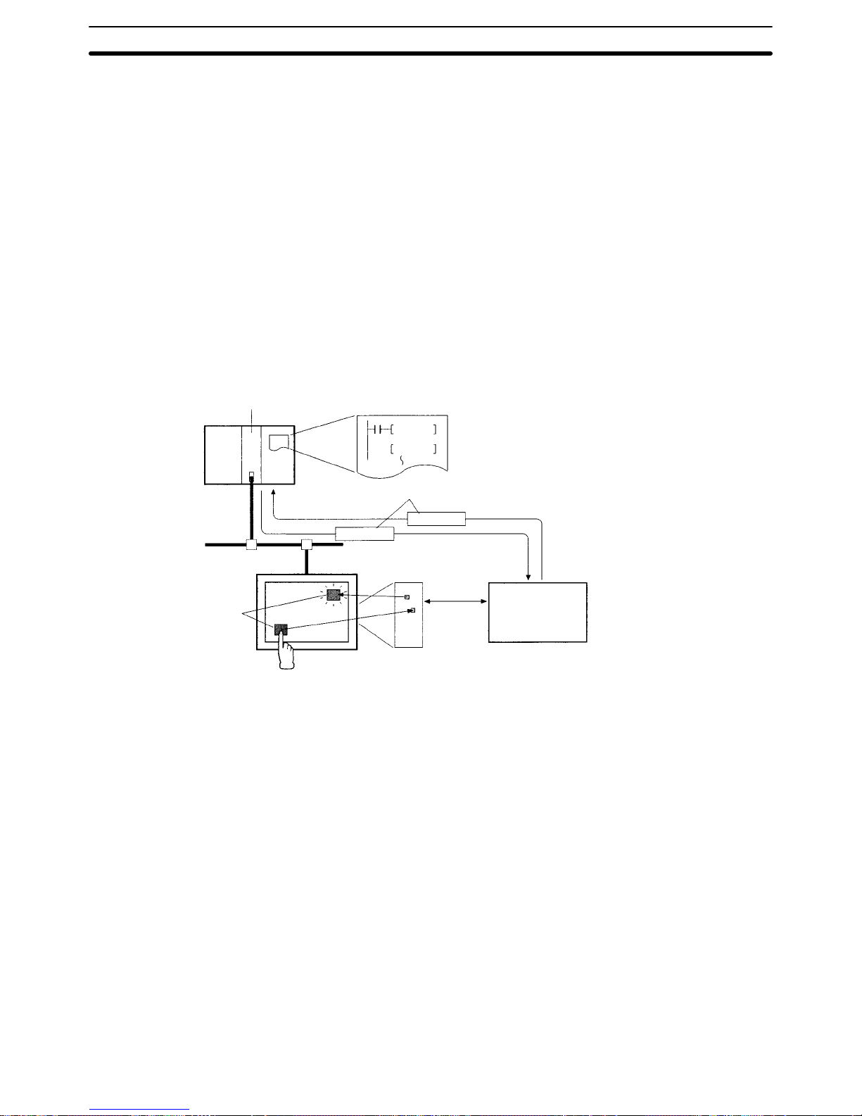
7-1SectionOverview of Message Communications
84
7-1 Overview of Message Communications
Explicit messages can be sent between nodes in a DeviceNet network to transfer data and control other nodes.
The DeviceNet Interface Unit can freely write the contents of PT memory from
the Master using DeviceNet explicit messages. This function allows PT memory
outside of the allocated input and output areas to be accessed from the host to
control the PT or read its status.
7-1-1 Exchanging Data with the DeviceNet Interface Unit
Data can be exchanged between the host (Master) and a DeviceNet Interface
Unit using message communications to control the PT or read its status.
PT data (control/notify areas, elements, etc.) must be allocated to PT memory to
enable explicit message communications from the Master (PC) to the PT via the
DeviceNet Interface Unit. (The allocation method is the same as a regular link
method.)
IOWR
CMND
or
Master Unit
PC
Send an explicit message command
with an IOWR or CMND instruction
to read or write PT memory.
Explicit messages
Response
Command
PT
Elements
Allocation
PT memory
within the PT
All areas
can be
read/written
DeviceNet Interface Unit
Elements on the PT screen
can be directly accessed
using PT memory.
The command from the Master (host) is
interpreted, data is read from (written to)
the specified location in PT memory,
and the read data (command result) is
returned as a response.
Reference 1. Use the EXPLICIT MESSAGE SEND (28 01) FINS command when send-
ing an explicit message from an OMRON Master Unit.
With CVM1/CV-series PCs, send FINS commands with the CMND instruc-
tion. With CS1-series or C200HX/HG/HE PCs, send FINS commands with
the IOWR instruction.
2. Explicit messages cannot be sent when a C200HS is used as the Master.
(Data can only be read and written with remote I/O communications.)
7-1-2 Data Flow of Explicit Messages
When sending an explicit message, execute the CMND or IOWR instruction in
the ladder program to send the EXPLICIT MESSAGE SEND (28 01) FINS command to the DeviceNet Master Unit in the local node.
The Master Unit removes the FINS header from the received FINS command,
converts the command to an explicit message, and transmits it to the destination
Slave (PT).
Page 98

7-2SectionUsing Message Communications
85
Similarly, the Master Unit attaches a FINS header to the response from the PT
and returns it to the CPU Unit as a FINS response.
CPU Unit
CMND
or
IOWR
Explicit
message
FINS
header
Use 28 01 for the
FINS command code.
FINS
header
Response
DeviceNet
Master Unit
FINS
header
FINS
header
Explicit
message
Response
DeviceNet
network
OMRON Slave
or another
manufacturer’s
Master or Slave
Reference When sending an explicit message, specify the DeviceNet Master Unit in the lo-
cal node as the destination of the FINS command. The final destination Slave
(PT) is specified in the command data of the FINS command.
7-2 Using Message Communications
This section explains how to use the FINS command (code 28 01) that sends
explicit messages as well as the CMND and IOWR instructions. Refer to 7-3
Explicit Messages for details on the contents of explicit messages.
7-2-1 EXPLICIT MESSAGE SEND (FINS Command 28 01)
The EXPLICIT MESSAGE SEND command is used to send an explicit DeviceNet message to the DeviceNet Master Unit.
Command Block
0128
Destination node address
Service code
Instance ID Service dataClass IDCommand
code
242 bytes max.
01008A00
Response Block
Normal Response
0128
Source node address
Service code (see note)
No. of bytes
received
Service dataResponse
code
Command
code
240 bytes max.
00 00
Note For a normal response, the leftmost bit of the service code specified in the com-
mand will be turned ON and then returned. For example, a command service
code of 32 Hex is returned as B2 Hex in the response.
Error Responses
The following response is returned if an error occurs for the explicit message.
Page 99

7-2SectionUsing Message Communications
86
0128
Source node address
Service code 94 (hex)
No. of bytes
received
Response
code
Command
code
00 00 94 FF
General error code
Additional error code FF (hex)
The following response is returned if the explicit message cannot be sent or
times out.
0128
Response
code
Command
code
Destination node address (command): The node address of the destination
of the explicit message. (The node address of the local Master Unit is specified in
the control data for the CMND(194) or IOWR instruction, but the node address of
the actual destination is specified here in the FINS command.)
Service code (command, response): A service code defined for DeviceNet. In
a normal response, bit 15 of the service code specified in the command will be
turned ON and returned. In an error response, 94 hex will always be returned.
Class ID (command): The class ID of the destination of the explicit message.
The class ID is always 008A Hex when reading or writing the DeviceNet Interface Unit’s PT memory.
Instance ID (command): The instance ID of the destination of the explicit message. The instance ID is always 0001 Hex when reading or writing the DeviceNet Interface Unit’s PT memory.
Service data (command, response): The data defined for the services codes.
No. of bytes received (response): The number of bytes received from the des-
tination node address (local node).
Destination node address (response): The node address of the OMRON
Special I/O Slave Unit or slave manufactured by another company to which the
explicit message was sent is returned.
General Error Code (response): The following error codes may be returned.
General
error code
Error name Cause of error
0C Hex Object state conflict The PT is not able to process the message in
its current status.
08 Hex Service not supported The Service Code is not supported.
02 Hex Resource unavailable The Instance ID is not supported.
09 Hex Invalid attribute value The Attribute Value is not supported.
15 Hex Too much data The data string is too long.
13 Hex Not enough data The data string is too short or there is an odd
number of bytes.
14 Hex Attribute not supported The Attribute ID is not supported.
20 Hex Invalid parameter An incorrect PT memory address was
specified.
11 Hex Reply data too large More than 250 bytes of read data was
returned when reading PT memory.
16 Hex Object does not exist The Class ID is not supported.
Note 1. Unlike other FINS commands, this command is addressed to the local
node’s DeviceNet Master Unit. The actual destination of the explicit message is given in the command data, as described above.
Parameters
Page 100
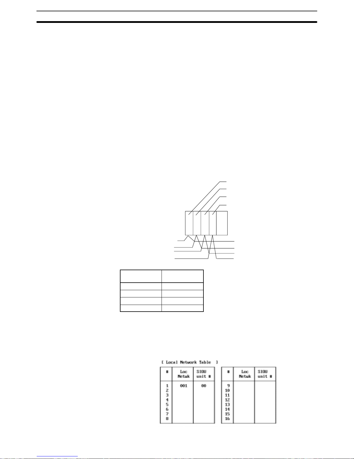
7-2SectionUsing Message Communications
87
Always specify the local node’s DeviceNet Master Unit in the control code of
the CMND or IOWR instruction. An error will occur if another node’s Master
Unit is specified.
2. If the DeviceNet Master Unit receives an explicit message, it will automatically return a response.
Reference Refer to 7-3 Explicit Messages for details on the service code, class ID, instance
ID, and service data to use when sending an explicit message to the DeviceNet
Master Unit.
7-2-2 Using the CMND Instruction in CVM1 and CV-series PCs
Use the CMND instruction when sending explicit messages from a CVM1/CVseries PC.
Reference The DeviceNet Master Unit must be registered in the routing table (local network
table) of the CVM1 or CV-series PC to execute the CMND(194) instruction from
the PC.
The local network table of the routing tables lists the unit numbers of the Communications Units mounted to the PC and the addresses of the Networks to
which each Unit belongs. An example local network table is shown below.
Unit #04
Unit #05
Unit #06
Unit #07
Network 1
Network 2
Network 3
Network 4
Address of local
network
CPU Bus Unit’s
unit number
001 04
002 05
003 06
004 07
The unit number of the DeviceNet Master Unit as a CPU Bus Unit is the number
set on the rotary switches on the front panel. The network address is the address
of the Network to which the CPU Bus Unit is connected.
Routing tables are set from the Support Software using the following display to
input the settings.
 Loading...