

Page 1

Cat. No. V063-E1-03
NT631 and NT631C
Programmable Terminals
Setup Manual
Page 2
NT631 and NT631C Programmable Terminals
Setup Manual
Revised September 2007
POWER
RUN
Page 3

iv
Page 4

Notice:
r
f
OMRON products are manufactured for use according to proper procedures by a qualified operator
and only for the purposes described in this manual.
The following conventions are used to indicate and classify precautions in this manual. Always heed
the information provided with them. Failure to heed precautions can result in injury to people or damage to property.
!DANGER Indicates an imminently hazardous situation which, if not avoided, will result in death or
serious injury. Additionally, there may be severe property damage.
!WARNING Indicates a potentially hazardous situation which, if not avoided, could result in death or
serious injury. Additionally, there may be severe property damage.
!Caution Indicates a potentially hazardous situation which, if not avoided, may result in minor or
moderate injury, or property damage.
OMRON Product References
All OMRON products are capitalized in this manual. The word “Unit” is also capitalized when it refers to
an OMRON product, regardless of whether or not it appears in the proper name of the product.
The abbreviation “Ch,” which appears in some displays and on some OMRON products, often means
“word” and is abbreviated “Wd” in documentation in this sense.
The abbreviation “PLC” means Programmable Controller. “PC” is used, however, in some Programming Device displays to mean Programmable Controller.
Visual Aids
The following headings appear in the left column of the manual to help you locate different types of
information.
OMRON, 2000
All rights reserved. No part of this publication may be reproduced, stored in a retrieval system, or transmitted, in any form, o
by any means, mechanical, electronic, photocopying, recording, or otherwise, without the prior written permission o
OMRON.
No patent liability is assumed with respect to the use of the information contained herein. Moreover, because OMRON is constantly striving to improve its high-quality products, the information contained in this manual is subject to change without
notice. Every precaution has been taken in the preparation of this manual. Nevertheless, OMRON assumes no responsibility
for errors or omissions. Neither is any liability assumed for damages resulting from the use of the information contained in
this publication.
Note Indicates information of particular interest for efficient and convenient opera-
tion of the product.
1,2,3... 1. Indicates lists of one sort or another, such as procedures, checklists, etc.
v
Page 5

vi
Page 6

TABLE OF CONTENTS
PRECAUTIONS . . . . . . . . . . . . . . . . . . . . . . . . . . . . . . . . . . . xv
1 Intended Audience. . . . . . . . . . . . . . . . . . . . . . . . . . . . . . . . . . . . . . . . . . . . . . . . . . . . . . . . . xvi
2 General Precautions. . . . . . . . . . . . . . . . . . . . . . . . . . . . . . . . . . . . . . . . . . . . . . . . . . . . . . . . xvi
3 Safety Precautions . . . . . . . . . . . . . . . . . . . . . . . . . . . . . . . . . . . . . . . . . . . . . . . . . . . . . . . . . xvi
SECTION 1
General. . . . . . . . . . . . . . . . . . . . . . . . . . . . . . . . . . . . . . . . . . . 1
1-1 Role and Operation of the NT631/NT631C . . . . . . . . . . . . . . . . . . . . . . . . . . . . . . . . . . . . . 2
1-2 Functions of the NT631/NT631C . . . . . . . . . . . . . . . . . . . . . . . . . . . . . . . . . . . . . . . . . . . . . 4
1-3 System Configuration . . . . . . . . . . . . . . . . . . . . . . . . . . . . . . . . . . . . . . . . . . . . . . . . . . . . . . 16
1-4 Communications with the Host . . . . . . . . . . . . . . . . . . . . . . . . . . . . . . . . . . . . . . . . . . . . . . . 18
1-5 Communications Using Memory Links . . . . . . . . . . . . . . . . . . . . . . . . . . . . . . . . . . . . . . . . 21
1-6 Before Operating . . . . . . . . . . . . . . . . . . . . . . . . . . . . . . . . . . . . . . . . . . . . . . . . . . . . . . . . . . 23
SECTION 2
Preparing for Connection . . . . . . . . . . . . . . . . . . . . . . . . . . . 25
2-1 Method for Connection to the Host . . . . . . . . . . . . . . . . . . . . . . . . . . . . . . . . . . . . . . . . . . . . 26
2-2 Names and Functions of Parts . . . . . . . . . . . . . . . . . . . . . . . . . . . . . . . . . . . . . . . . . . . . . . . . 29
SECTION 3
Hardware Settings and Connections. . . . . . . . . . . . . . . . . . . 31
3-1 Installation . . . . . . . . . . . . . . . . . . . . . . . . . . . . . . . . . . . . . . . . . . . . . . . . . . . . . . . . . . . . . . . 32
3-2 Connecting to the Support Tool. . . . . . . . . . . . . . . . . . . . . . . . . . . . . . . . . . . . . . . . . . . . . . . 35
3-3 Connecting a Printer . . . . . . . . . . . . . . . . . . . . . . . . . . . . . . . . . . . . . . . . . . . . . . . . . . . . . . . 36
3-4 Connecting a Bar Code Reader . . . . . . . . . . . . . . . . . . . . . . . . . . . . . . . . . . . . . . . . . . . . . . . 36
3-5 Using a Memory Unit . . . . . . . . . . . . . . . . . . . . . . . . . . . . . . . . . . . . . . . . . . . . . . . . . . . . . . 39
SECTION 4
Connecting to the Host from the RS-232C Port. . . . . . . . . . 47
4-1 Connecting to the RS-232C Port at the Host . . . . . . . . . . . . . . . . . . . . . . . . . . . . . . . . . . . . . 48
SECTION 5
Connecting to the Host from the RS-422A/485 Port . . . . . . 79
5-1 Connecting to the Host’s RS-232C Port . . . . . . . . . . . . . . . . . . . . . . . . . . . . . . . . . . . . . . . . 80
5-2 Connecting to the Host’s RS-422A/485 Port. . . . . . . . . . . . . . . . . . . . . . . . . . . . . . . . . . . . . 93
SECTION 6
System Menu Operation. . . . . . . . . . . . . . . . . . . . . . . . . . . . . 127
6-1 System Menu Operation Flow. . . . . . . . . . . . . . . . . . . . . . . . . . . . . . . . . . . . . . . . . . . . . . . . 129
6-2 Starting the NT631/NT631C . . . . . . . . . . . . . . . . . . . . . . . . . . . . . . . . . . . . . . . . . . . . . . . . . 129
6-3 Operation Modes and the System Menu . . . . . . . . . . . . . . . . . . . . . . . . . . . . . . . . . . . . . . . . 130
6-4 Memory Initialization . . . . . . . . . . . . . . . . . . . . . . . . . . . . . . . . . . . . . . . . . . . . . . . . . . . . . . 135
vii
Page 7

TABLE OF CONTENTS
6-5 Operations in the System Installer Mode. . . . . . . . . . . . . . . . . . . . . . . . . . . . . . . . . . . . . . . . 144
6-6 Transmitting the Screen Data . . . . . . . . . . . . . . . . . . . . . . . . . . . . . . . . . . . . . . . . . . . . . . . . 149
6-7 Setting Conditions for Communications with Host by Using Memory Switches. . . . . . . . . 152
6-8 Starting Operation . . . . . . . . . . . . . . . . . . . . . . . . . . . . . . . . . . . . . . . . . . . . . . . . . . . . . . . . . 163
6-9 Various System Settings . . . . . . . . . . . . . . . . . . . . . . . . . . . . . . . . . . . . . . . . . . . . . . . . . . . . 164
6-10 Setting the Bar Code Reader Input Function. . . . . . . . . . . . . . . . . . . . . . . . . . . . . . . . . . . . . 184
6-11 System Maintenance . . . . . . . . . . . . . . . . . . . . . . . . . . . . . . . . . . . . . . . . . . . . . . . . . . . . . . . 187
6-12 Programming Console Function . . . . . . . . . . . . . . . . . . . . . . . . . . . . . . . . . . . . . . . . . . . . . . 214
6-13 Device Monitor Function. . . . . . . . . . . . . . . . . . . . . . . . . . . . . . . . . . . . . . . . . . . . . . . . . . . . 220
6-14 Version Display . . . . . . . . . . . . . . . . . . . . . . . . . . . . . . . . . . . . . . . . . . . . . . . . . . . . . . . . . . . 223
SECTION 7
Troubleshooting and Maintenance . . . . . . . . . . . . . . . . . . . . 225
7-1 Troubleshooting. . . . . . . . . . . . . . . . . . . . . . . . . . . . . . . . . . . . . . . . . . . . . . . . . . . . . . . . . . . 226
7-2 Responding to Displayed Error Messages. . . . . . . . . . . . . . . . . . . . . . . . . . . . . . . . . . . . . . . 229
7-3 Maintenance of the NT631/NT631C. . . . . . . . . . . . . . . . . . . . . . . . . . . . . . . . . . . . . . . . . . . 235
7-4 Inspection and Cleaning . . . . . . . . . . . . . . . . . . . . . . . . . . . . . . . . . . . . . . . . . . . . . . . . . . . . 242
Appendices
A Specifications . . . . . . . . . . . . . . . . . . . . . . . . . . . . . . . . . . . . . . . . . . . . . . . . . . . . . . . . . . . . 245
B Dimensions . . . . . . . . . . . . . . . . . . . . . . . . . . . . . . . . . . . . . . . . . . . . . . . . . . . . . . . . . . . . . . 255
C Using an RS-232C/RS-422A Adapter . . . . . . . . . . . . . . . . . . . . . . . . . . . . . . . . . . . . . . . . . 259
D Transporting and Storing the NT631/NT631C . . . . . . . . . . . . . . . . . . . . . . . . . . . . . . . . . . . 265
E Making the Cable . . . . . . . . . . . . . . . . . . . . . . . . . . . . . . . . . . . . . . . . . . . . . . . . . . . . . . . . . 267
F Making the Cable for Connecting a PLC . . . . . . . . . . . . . . . . . . . . . . . . . . . . . . . . . . . . . . . 271
G Making the Cable for Connection to a Bar Code Reader . . . . . . . . . . . . . . . . . . . . . . . . . . . 273
H Making the Cable for Connection to a Printer . . . . . . . . . . . . . . . . . . . . . . . . . . . . . . . . . . . 275
I Relationship between system program and hardware . . . . . . . . . . . . . . . . . . . . . . . . . . . . . 277
J Model List . . . . . . . . . . . . . . . . . . . . . . . . . . . . . . . . . . . . . . . . . . . . . . . . . . . . . . . . . . . . . . . 281
K Option List . . . . . . . . . . . . . . . . . . . . . . . . . . . . . . . . . . . . . . . . . . . . . . . . . . . . . . . . . . . . . . 287
Index. . . . . . . . . . . . . . . . . . . . . . . . . . . . . . . . . . . . . . . . . . . . . 291
Revision History . . . . . . . . . . . . . . . . . . . . . . . . . . . . . . . . . . . 295
viii
Page 8

About this Manual:
This manual describes connecting the NT-series NT631 and NT631C Programmable Terminals (PTs)
to a PLC (Programmable Controller) or other host and peripheral devices, and the settings required for
communications and applications. It includes the sections described below.
Please read this manual carefully and be sure you understand the information provided before
attempting to install and operate the Programmable Terminal.
Section 1 provides fundamental information about the functions and features of the PTs, types of connection, communications methods, etc. This information will enable you to understand the applications
of the PTs.
Section 2 describes the connection methods that are possible with the PTs, and the functions of the
parts of PTs, as the required knowledge before connecting to the host and to the peripheral devices.
Section 3 describes the settings of the PTs and methods for connection to peripheral devices.
Section 4 describes the method for connecting to the host using the RS-232C port of the PT.
Section 5 describes the method for connecting to the host using the RS-422A/485 port of the PT.
Section 6 describes the operation of the System Menu, focusing on the procedure to start the PT.
Functions that are convenient when using the PT and those that are useful for system maintenance
are also explained here.
Section 7 describes the action to take when errors occur in the PT, and how to carry out maintenance
and inspection to prevent the occurrence of errors.
The Appendices provide specifications, dimensions, procedures for using an RS-232C/RS-422A
Adapter, procedures for transporting and storing the PT, information on cable preparation, information
on the relationship between the system program and hardware, and product lists.
!WARNING Failure to read and understand the information provided in this manual may result in per-
sonal injury or death, damage to the product, or product failure. Please read each section
in its entirety and be sure you understand the information provided in the section and
related sections before attempting any of the procedures or operations given.
ix
Page 9

Related Manuals:
Related manuals are listed below.
The @ symbol at the end of the catalog number is the revision number.
Connecting and Setting Up the Programmable Terminal
• NT631 and NT631C PT Setup Manual (V063-E1-@, this manual)
This manual describes connecting the Programmable Terminals to a host and peripheral devices and
settings required for communications and applications.
The functions and actual operating methods for the NT631 and NT631C PTs are provided in the Refer-
ence Manual (V064-E1-@).
Programmable Terminal Functions and Operation
• NT31/31C/631/631C PT Reference Manual (V064-E1-@)
This manual is used for any of the following PTs: NT31, NT31C, NT631, and NT631C. It describes
screen configurations, part functions, host control methods, and other application information.
PT connection and setup procedures are described in the NT631 and NT631C PT Setup Manual
(V063-E1-@).
Creating and Transferring Screen Data, and Installing the System Program
• NT-series Support Tool for Windows Ver. 4.@ Operation Manual (V061-E1-@)
The screens displayed on the NT631 and NT631C PTs are created with the Support Tool and transferred to the PT. This manual describes how to create and transfer screen data. It also describes how
to download a system program to a PT using the System Installer.
The NT-series Support Tool for Windows is normally referred to as merely the Support Tool.
Connecting to Controllers Not Made by OMRON
• PLC Connection Manual (V042-E1-@)
The NT631 and NT631C PTs can be connected to controllers in the following series: Mitsubishi A
Series and FX Series. This manual describes the connection and setup methods for these controllers.
The NT-series Support Tool for Windows Version 4.@ is required to connect the NT631 and NT631C
PTs to these controllers.
• NT31/NT631 Multi Vendor Connection Manual (V060-E1-@)
The NT631 and NT631C PTs can be connected to controllers in the following series: Allen-Bradley
SLC 500 Series, GE Fanuc 90-20 and 90-30 Series, and Siemens S7-300 and S7-400 Series. This
manual describes the connection and setup methods for these controllers.
x
Page 10

Read and Understand this Manual
Please read and understand this manual before using the product. Please consult your OMRON
representative if you have any questions or comments.
Warranty and Limitations of Liability
WARRANTY
OMRON's exclusive warranty is that the products are free from defects in materials and workmanship for a
period of one year (or other period if specified) from date of sale by OMRON.
OMRON MAKES NO WARRANTY OR REPRESENTATION, EXPRESS OR IMPLIED, REGARDING NONINFRINGEMENT, MERCHANTABILITY, OR FITNESS FOR PARTICULAR PURPOSE OF THE
PRODUCTS. ANY BUYER OR USER ACKNOWLEDGES THAT THE BUYER OR USER ALONE HAS
DETERMINED THAT THE PRODUCTS WILL SUITABLY MEET THE REQUIREMENTS OF THEIR
INTENDED USE. OMRON DISCLAIMS ALL OTHER WARRANTIES, EXPRESS OR IMPLIED.
LIMITATIONS OF LIABILITY
OMRON SHALL NOT BE RESPONSIBLE FOR SPECIAL, INDIRECT, OR CONSEQUENTIAL DAMAGES,
LOSS OF PROFITS OR COMMERCIAL LOSS IN ANY WAY CONNECTED WITH THE PRODUCTS,
WHETHER SUCH CLAIM IS BASED ON CONTRACT, WARRANTY, NEGLIGENCE, OR STRICT
LIABILITY.
In no event shall the responsibility of OMRON for any act exceed the individual price of the product on which
liability is asserted.
IN NO EVENT SHALL OMRON BE RESPONSIBLE FOR WARRANTY, REPAIR, OR OTHER CLAIMS
REGARDING THE PRODUCTS UNLESS OMRON'S ANALYSIS CONFIRMS THAT THE PRODUCTS
WERE PROPERLY HANDLED, STORED, INSTALLED, AND MAINTAINED AND NOT SUBJECT TO
CONTAMINATION, ABUSE, MISUSE, OR INAPPROPRIATE MODIFICATION OR REPAIR.
xi
Page 11

Application Considerations
SUITABILITY FOR USE
OMRON shall not be responsible for conformity with any standards, codes, or regulations that apply to the
combination of products in the customer's application or use of the products.
At the customer's request, OMRON will provide applicable third party certification documents identifying
ratings and limitations of use that apply to the products. This information by itself is not sufficient for a
complete determination of the suitability of the products in combination with the end product, machine,
system, or other application or use.
The following are some examples of applications for which particular attention must be given. This is not
intended to be an exhaustive list of all possible uses of the products, nor is it intended to imply that the uses
listed may be suitable for the products:
• Outdoor use, uses involving potential chemical contamination or electrical interference, or conditions or
uses not described in this manual.
• Nuclear energy control systems, combustion systems, railroad systems, aviation systems, medical
equipment, amusement machines, vehicles, safety equipment, and installations subject to separate
industry or government regulations.
• Systems, machines, and equipment that could present a risk to life or property.
Please know and observe all prohibitions of use applicable to the products.
NEVER USE THE PRODUCTS FOR AN APPLICATION INVOLVING SERIOUS RISK TO LIFE OR
PROPERTY WITHOUT ENSURING THAT THE SYSTEM AS A WHOLE HAS BEEN DESIGNED TO
ADDRESS THE RISKS, AND THAT THE OMRON PRODUCTS ARE PROPERLY RATED AND
INSTALLED FOR THE INTENDED USE WITHIN THE OVERALL EQUIPMENT OR SYSTEM.
PROGRAMMABLE PRODUCTS
OMRON shall not be responsible for the user's programming of a programmable product, or any
consequence thereof.
xii
Page 12

Disclaimers
CHANGE IN SPECIFICATIONS
Product specifications and accessories may be changed at any time based on improvements and other
reasons.
It is our practice to change model numbers when published ratings or features are changed, or when
significant construction changes are made. However, some specifications of the products may be changed
without any notice. When in doubt, special model numbers may be assigned to fix or establish key
specifications for your application on your request. Please consult with your OMRON representative at any
time to confirm actual specifications of purchased products.
DIMENSIONS AND WEIGHTS
Dimensions and weights are nominal and are not to be used for manufacturing purposes, even when
tolerances are shown.
PERFORMANCE DATA
Performance data given in this manual is provided as a guide for the user in determining suitability and does
not constitute a warranty. It may represent the result of OMRON's test conditions, and the users must
correlate it to actual application requirements. Actual performance is subject to the OMRON Warranty and
Limitations of Liability.
ERRORS AND OMISSIONS
The information in this manual has been carefully checked and is believed to be accurate; however, no
responsibility is assumed for clerical, typographical, or proofreading errors, or omissions.
xiii
Page 13

xiv
Page 14

PRECAUTIONS
This section provides general precautions for using the Programmable Terminal.
The information contained in this section is important for the safe and reliable application of the Programmable
Terminal. You must read this section and understand the information contained before attempting to set up or operate
a Programmable Terminal.
1 Intended Audience . . . . . . . . . . . . . . . . . . . . . . . . . . . . . . . . . . . . . . . . . . . . . xvi
2 General Precautions . . . . . . . . . . . . . . . . . . . . . . . . . . . . . . . . . . . . . . . . . . . . xvi
3 Safety Precautions . . . . . . . . . . . . . . . . . . . . . . . . . . . . . . . . . . . . . . . . . . . . . xvi
xv
Page 15

Intended Audience 1
1 Intended Audience
This manual is intended for the following personnel, who must also have
knowledge of electrical systems (an electrical engineer or the equivalent).
• Personnel in charge of introducing FA systems into production facilities.
• Personnel in charge of designing FA systems.
• Personnel in charge of installing and connecting FA systems.
• Personnel in charge of managing FA systems and facilities.
2 General Precautions
The user must operate the product according to the performance specifications described in the operation manuals.
Before using the product under conditions which are not described in the
manual or applying the product to nuclear control systems, railroad systems,
aviation systems, vehicles, combustion systems, medical equipment, amusement machines, safety equipment, and other systems, machines and equipment that may have a serious influence on lives and property if used
improperly, consult your OMRON representative.
Make sure that the ratings and performance characteristics of the product are
sufficient for the systems, machines, and equipment, and be sure to provide
the systems, machines, and equipment with double safety mechanisms.
This manual provides information for using the Programmable Terminal. Be
sure to read this manual before attempting to use the software and keep this
manual close at hand for reference during operation.
!WARNING It is extremely important that Programmable Terminals and related devices be
used for the specified purpose and under the specified conditions, especially
in applications that can directly or indirectly affect human life. You must consult with your OMRON representative before applying Programmable Terminals to the above-mentioned applications.
!WARNING Do not use input functions such as PT touch switches for applications where
danger to human life or serious damage is possible, or for emergency switch
applications.
3 Safety Precautions
Read these safety precautions carefully and make sure you understand them
before using the Programmable Terminal so that you can use it safely and correctly.
Safety Conventions and their Meanings
This operation manual uses the following conventions and symbols to indicate
cautions, warnings, and dangers in order to ensure safe use of the NT631/
631C.
The cautions, warnings, and dangers shown here contain important information related to safety. This instructions in these cautions, warnings, and dangers must be observed.
The conventions used and their meanings are presented below.
xvi
Page 16
Safety Precautions 3
!WARNING Indicates information that, if not heeded, could possibly result in loss of life or
serious injury.
!Caution Indicates information that, if not heeded, could result in relatively serious or
minor injury, damage to the product, or faulty operation.
WARNING
Do not attempt to take the unit apart and do not touch any
internal parts while the power is being supplied. Doing either
of these may result in electrical shock.
WARNING
Switch OFF the NT631C power before replacing the
backlight. Otherwise you could sustain an electric shock.
xvii
Page 17

Safety Precautions 3
xviii
Page 18

SECTION 1
General
This section provides fundamental information about the functions and features of the NT631/NT631C, types of
connection, communications methods, etc. This information will enable you to understand the applications of the
NT631/NT631C.
1-1 Role and Operation of the NT631/NT631C. . . . . . . . . . . . . . . . . . . . . . . . . . 2
1-1-1 Operation of an NT631/NT631C at an FA Production Site . . . . . . . 2
1-1-2 Operations of the NT631/NT631C . . . . . . . . . . . . . . . . . . . . . . . . . 3
1-2 Functions of the NT631/NT631C. . . . . . . . . . . . . . . . . . . . . . . . . . . . . . . . . . 4
1-2-1 Features . . . . . . . . . . . . . . . . . . . . . . . . . . . . . . . . . . . . . . . . . . . . . . 4
1-2-2 Comparison between NT631 and NT631C . . . . . . . . . . . . . . . . . . . 7
1-2-3 Comparison between NT620S/NT620C/NT625C and NT631/NT631C 8
1-2-4 Principal Functions of NT631/NT631C. . . . . . . . . . . . . . . . . . . . . . 10
1-2-5 Displays . . . . . . . . . . . . . . . . . . . . . . . . . . . . . . . . . . . . . . . . . . . . . . 12
1-3 System Configuration. . . . . . . . . . . . . . . . . . . . . . . . . . . . . . . . . . . . . . . . . . . 16
1-3-1 Peripheral Devices That Can Be Connected . . . . . . . . . . . . . . . . . . 17
1-3-2 Connecting to the Host. . . . . . . . . . . . . . . . . . . . . . . . . . . . . . . . . . . 18
1-4 Communications with the Host . . . . . . . . . . . . . . . . . . . . . . . . . . . . . . . . . . . 18
1-4-1 Direct Connection Function . . . . . . . . . . . . . . . . . . . . . . . . . . . . . . . 18
1-4-2 Host Link . . . . . . . . . . . . . . . . . . . . . . . . . . . . . . . . . . . . . . . . . . . . . 19
1-4-3 NT Link . . . . . . . . . . . . . . . . . . . . . . . . . . . . . . . . . . . . . . . . . . . . . . 19
1-4-4 Connecting to Other Companies’ PLCs. . . . . . . . . . . . . . . . . . . . . . 21
1-5 Communications Using Memory Links . . . . . . . . . . . . . . . . . . . . . . . . . . . . . 21
1-5-1 Memory Link . . . . . . . . . . . . . . . . . . . . . . . . . . . . . . . . . . . . . . . . . . 21
1-5-2 Comparison between Direct Connection and Memory Link . . . . . . 22
1-5-3 Memory Link Online Transfer Function . . . . . . . . . . . . . . . . . . . . . 22
1-6 Before Operating . . . . . . . . . . . . . . . . . . . . . . . . . . . . . . . . . . . . . . . . . . . . . . 23
1
Page 19
Role and Operation of the NT631/NT631C Section 1-1
1-1 Role and Operation of the NT631/NT631C
The NT631/NT631C is a sophisticated display unit (Programmable Terminal)
which automatically displays information and can also be used for operations
when necessary. The following gives a general description of the role and
operation of the NT631/NT631C for those using a programmable terminal
(PT) for the first time.
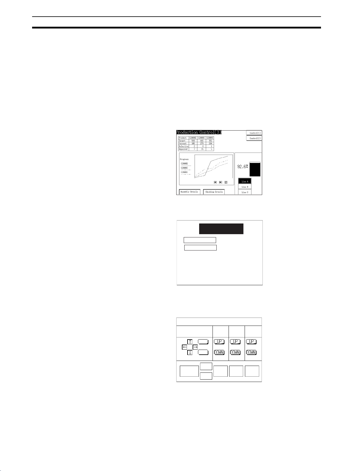
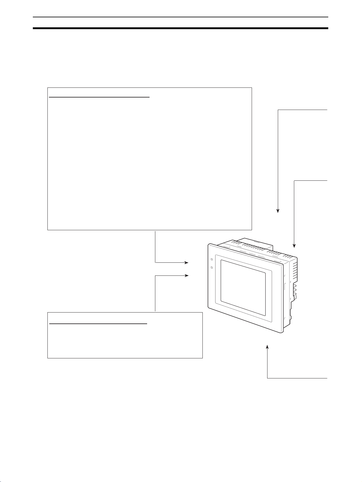
1-1-1 Operation of an NT631/NT631C at an FA Production Site
Production Line Status
Monitoring
Directions to Workers on
the Shop Floor
The NT631/NT631C displays real-time information about the system and
equipment operating status, etc. Its power of expression is enhanced by
graphs and other visuals, making the displays easy to understand.
The NT631/NT631C warns of system or equipment failures and prompts the
appropriate remedial action.
Alarm
Assembly line B
Positioning pin
is defective. Line stopped.
Check the following.
1. Defective pin L3
2. Position of dog M2
3. Mounting of photosensor P5
Panel Switch Functions Setting touch switches on the NT631/NT631C allows workers to use the
NT631/NT631C as an operating panel; the results of the operations are transmitted to the host.
Electroplating control
Wash .
Transpor t
Int. stop
Clamp
Unclamp
Adv.
Rev.
Electr.
head
Electrolyte
head
Wash
Corr. prv.
head
Corr.
prv.fluid
2
Page 20
Role and Operation of the NT631/NT631C Section 1-1
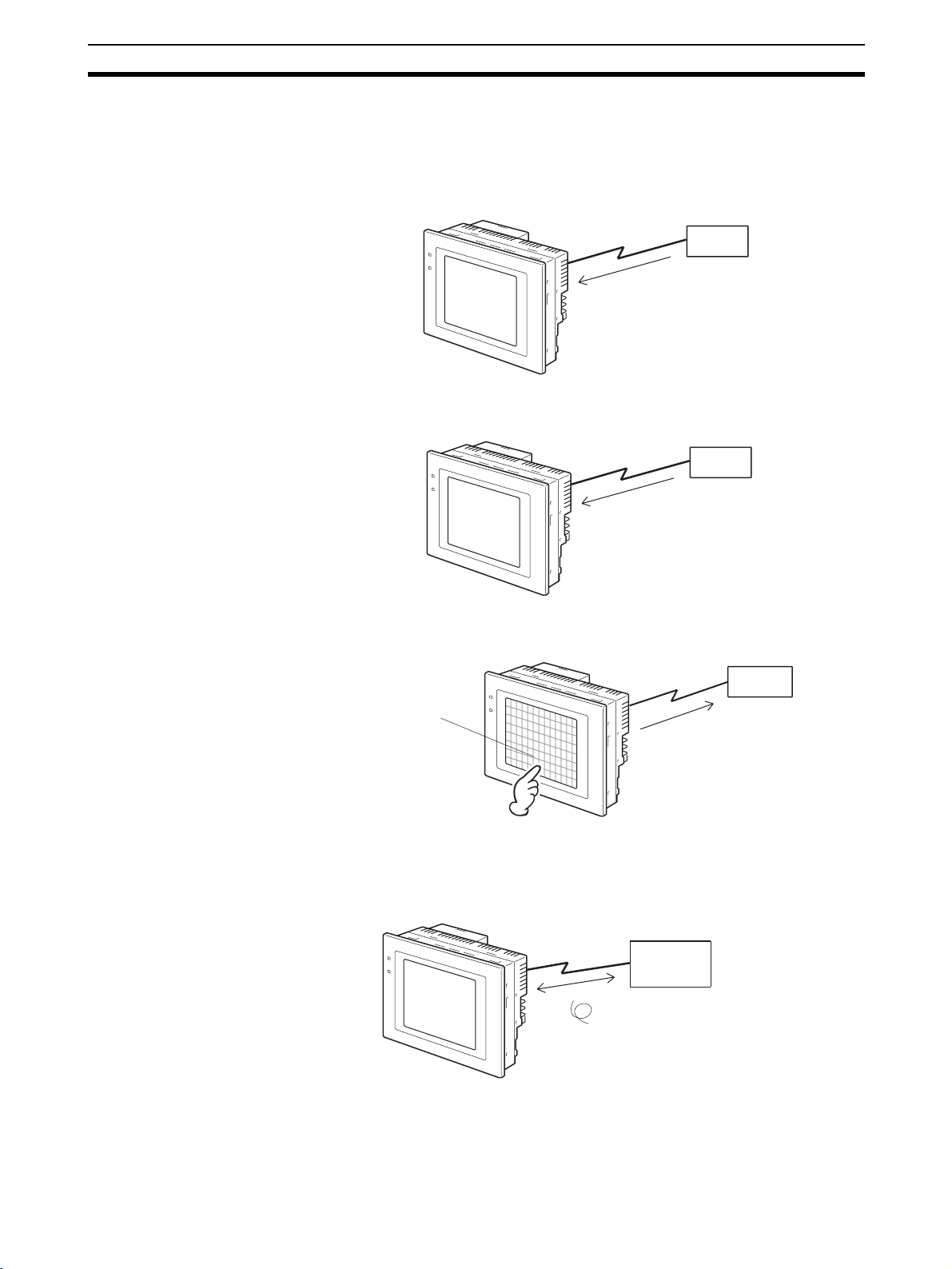
1-1-2 Operations of the NT631/NT631C
Displays Screens The information to be displayed (screen data) can be created on a computer
using the Support Tool and stored in the NT631/NT631C. The screen data
can be displayed on the NT631/NT631C in response to instructions from the
host or touch switch operation.
Host
The screen data designated by
instructions from the host or touch
switch operation is displayed.
Receives Data from a Host The NT631/NT631C can be connected to the host by a host link or NT link
and receive necessary data from the host.
Host Link, NT link
Host
Sends Data to a Host Data input using the touch panel (switch ON/OFF statuses, numeric values,
character strings) can be transmitted to the host.
Host
Touch panel
ON/OFF information, numeric
data, etc.
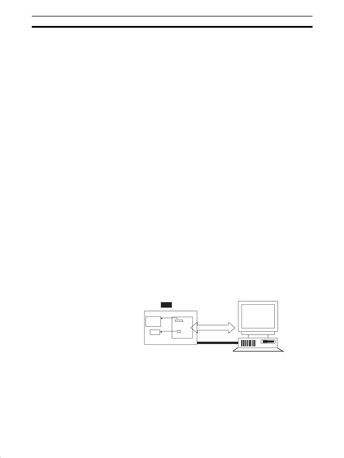
Screen Data The screen data to be displayed on the NT631/NT631C can be created on a
personal computer using the Support Tool. Connect the NT631/NT631C to
the personal computer with an RS-232C cable and transmit the screen data to
the NT631/NT631C.
Create screen data.
RS-232C
Screen data
Personal
computer
(Support Tool)
When the host is connected at serial port A,
the personal computer is only connected
when communicating screen data between
the NT631/NT631C and Support Tool.
3
Page 21

Functions of the NT631/NT631C Section 1-2
1-2 Functions of the NT631/NT631C
The NT631/NT631C has the following features.
1-2-1 Features
Slim Body • High-performance in a low-profile body (50 mm or less in the panel*).
• The communications cable connectors are housed in the PT so that they
do not protrude from the PT.
* When mounted in a panel of the recommended thickness (page 32).
Construction Best Suited
to the FA Environment
• The display panel is provided with a high-contrast monochrome EL display for the NT631-ST211@-EV2, an STN color LCD display with backlight for the NT631C-ST141@-EV2, and a TFT color LCD high-definition
display for NT631C-ST153@-EV3.
• The backlight unit and battery can be replaced at the operation site. (The
backlight for the NT631C-ST153@-EV3, however, cannot be replaced by
the user.)
• Protection equivalent to oil-proof IP65*, and waterproof structure equivalent to the NEMA4 standard*.
* The panel may not be usable in environments where it is exposed to oil
for long periods.
640 dots
POWER
RUN
480 dots
Wide angle of visibility
Touch Switch Operation Contrast and brightness are adjustable by touch switch operations (for
NT631C-ST141@-EV2 only).
Compatibility with Other
PTs
• There is upward compatibility between the NT631/NT631C and the following models for screen data and user programs: NT11S, NT20S, NT30,
NT30C, NT31, NT31 NT600S, NT610G, NT610C, NT620S, NT620C,
NT625C. (After being read to the Support Tool, screens must be modified
in accordance with the screen size. Depending on the function used, partial modification of programs may also be necessary. For details on the
compatibility of screen data, refer to the NT31/NT31C/NT631/NT631C
Programmable Terminal Reference Manual and the NT-series Support
Tool Operation Manual.
• The dimensions of the panel cut-out to accommodate the NT631/NT631C
are the same as for the NT625C.
4
Page 22

Functions of the NT631/NT631C Section 1-2
Two Ports Featured as
Standard:
Rapid System Program &
Screen Data Changes
Possible Using a Memory
Unit.
Screen Data Check
Function
Large Increase in
Maximum Number of
Registered Elements
Binary Data can be Read
to/Written from the Host
Character Display Using
High Definition Fonts
Port A for Common Use by Support Tool/Host and Port B for Exclusive
Use by the Host
• Communications with the host is possible via another port while connected to the Support Tool.
• Reading bar code data from a bar code reader is possible via another port
while communicating with the host.
• Installing a Memory Unit (type NT-MF261) on the rear of the NT631/
NT631C makes it easy to write screen data into the NT631/NT631C on
site. This enables a rapid response to setup changes.
• NT631/NT631C can store a system program into a Memory Unit. This
enables the system to handle more flexible setups.
Screen data can be checked simply by operations at the NT631/NT631C system menu, without connecting up to the Support Tool.
The number of elements that can be registered on one screen has been considerably increased, making it possible to create more expressive screens.
For details, refer to Display Restrictions in Appendix A Specifications of the
NT31/NT31C/NT631/NT631C Programmable Terminal Reference Manual.
It is now possible to write binary data stored in words at the host directly to the
NT631/NT631C. This makes data conversion by a program at the host unnecessary, reducing the load on the host.
Any quadrupled characters are displayed with a 32 dot high-definition font.
Simple Version Upgrades By using the system installer supplied with the Support Tool (Type NT-
ZJCAT1-EV4), the system program at the NT631/NT631C can be changed
easily from a personal computer.
Complies with
International Standards
Compatible with Other
Vendors’ Devices
Multiple Windows Up to 3 windows can be displayed simultaneously in the normal screen. A 9-
High-speed 1:N NT Link The V2 versions are compatible with the high-speed 1:N NT Link as well as
Additional Mathematical
Functions
The NT631/NT631C meets UL/CSA standards and EC directives.
Compatible with Sequencers in the following series: Mitsubishi A-series (Calculator Link) and FX-series (Programming Console), Allen-Bradley SLC 500
Series, GE Fanuc 90-20 and 90-30 Series, and Siemens S7-300 and S7-400
Series. Specialized system programs can be installed that allow the NT631/
NT631C to be controlled from other companies’ Sequencers.
word window control area has been allocated to the host; the contents of
these 9 words can be changed from the Host to open, close, and move windows.
the earlier standard 1:N NT Link.
Operands (values referenced by formula) can be registered to allow the PT to
perform calculations automatically and write the results of those calculations
to numeral memory tables or words in the host.
5
Page 23

Functions of the NT631/NT631C Section 1-2
Device Monitor Function The new device monitor function can be used to change the PLC’s operating
mode or display/change values in the PLC’s memory areas. The present values (PVs) of several words can be listed with the device monitor.
Interlock Function PT operations and inputs can be disabled from the PLC if interlock bits have
been allocated in the PLC for the corresponding PT touch switches, numeric
inputs, or string inputs.
Improved Lamp/Touch
Switch Labels
NT30/NT30C and NT620S/
NT620C/NT625C
Emulation
Additional CS/CJ-series
Data Areas Accessible
The following displays can be performed with lamp or touch switch labels:
• Display several lines of labels.
• Switch the display between different labels when OFF and ON.
• Display the numeral memory table contents as labels.
• Display the string memory table contents as labels.
The word configuration of the PT status control area and PT status notify area
can be set to emulate those of the NT30/NT30C or NT620S/NT620C/
NT625C; this mode is called NT30/620 compatible mode.
When the PT is operating in NT30/620 compatible mode, it will be equivalent
to an NT30/NT30C or NT620S/NT620C/NT625C in the functions listed below.
The PT retains full V2 functionality in all functions other than the ones listed
below. Refer to Appendix C in the NT31/NT31C/NT631/NT631C Programma-
ble Terminal Reference Manual for more details.
• Word configuration and functions of the PT status control area and PT
status notify area
• Image/library codes
• Insertion of image/library data into character strings
Data areas in CS/CJ-series PLCs that were previously inaccessible can be
accessed. The data areas listed below can be accessed (read/written).
All banks in the EM area, timer completion flags (TU), counter completion
flags (CU), Work areas (WR), Task flags (TK), and the HR area.
Recipe Function You can set the data (numeric values) for multiple words in record units using
the tabular elements on the PT screen, and write these settings in a single
operation to words on the host (i.e., PLC or PT memory) using a touch switch
operation on the PT Unit. Also, multiple words of numeric data can be read
from the host in one operation. In this way, groups of parameter settings can
be edited at the PT Unit, and written to or read from the host.
Adjusting Contrast and
Brightness During PT
Operation
You can display the brightness and contrast adjustment screen using either
the touch switch or commands from the host, even while the PT is in operation.
6
Page 24

Functions of the NT631/NT631C Section 1-2
1-2-2 Comparison between NT631 and NT631C
Two NT631 models — the NT631, which is capable of versatile graphic displays (EL display, yellow), and the NT631C, which is also capable of color display — are available. The differences between the NT631 and NT631C are
tabled below:
Function NT631-ST211@-EV2 NT631C-ST141@-EV2 NT631C-ST153@-EV3
Type NT631-ST211-EV2 (Beige)
Display
panel
NT631-ST211B-EV2 (Black)
Monochrome EL display STN color LCD display
Beige and black are the front panel colors of each NT631/NT631C types.
NT631C-ST141-EV2 (Beige)
NT631C-ST141B-EV2 (Black)
(with white backlight)
NT631C-ST153-EV3 (Beige)
NT631C-ST153B-EV3 (Black)
TFT color LCD display
(with white backlight)
7
Page 25

Functions of the NT631/NT631C Section 1-2
1-2-3 Comparison between NT620S/NT620C/NT625C and NT631/
NT631C
Item NT620S/NT620C/NT625C NT631/NT631C
Support Tool used NT-ZJCAT1-EV4 or NT-ZA3AT-EV2 NT-ZJCAT1-EV4
DIP switches On rear of PT None (software settings)
Use of Memory Unit Not possible Possible
RS-232C interface Connector (9-pin) also used as port for
screen data transfer.
RS-422A/485 interface NT620S/NT620C: None
NT625C: Terminal block (DIP-switch
selectable between RS232C and RS422A/485)
Replacement backlight NT620C-CFL01 (NT620C)
NT610C-CFL02 (NT625C)
NT631/NT631C system program data
High-speed 1:N NT Link Not possible Possible
Memory
Link
LCD contrast adjustment By a control on the rear of the PT By touch panel operation
Backlight brightness adjustment
Number of user-registered
screens
Screen data capacity
(User program memory)
Numeral string data Maximum of 1000 Maximum of 2000
Character string data Maximum of 1000 Maximum of 2000
Bit data 256 Maximum of 1000
Mathematical tables None 256 max.
Image data Maximum of 224
Library data Maximum of 896
Method for storing numeric
values
(numeral memory data and PT
status control area)
PT status control area size 4 words
PT status notify area size 3 words
Window control area size None 9 CH
Registering continuous screen Possible Not possible (Use a screen switchover as a sub-
Lamp/Touch switch labels Fixed display (1 line only) - Multiple lines can be displayed
System program Exclusive use by Memory Link Same as OMRON connection
Screen data Shared with OMRON connection Exclusive use by Memory Link
*1
NT620-ZS3AT-EV1/EMV1
(including system installer)
Not possible By touch panel operation
Maximum of 2000 Maximum of 3999
NT620S: 512 KB
NT620C/NT625C: 1 MB
Fixed as BCD (binary coded decimal) Selectable from BCD (binary coded decimal) or
- Serial port A connector (also used for screen
data transfer, 9-pin)
- Serial port B connector (for host communications only, 9-pin)
Terminal block (serial port B; memory-switch
selectable between RS232C and RS-422A/485)
NT631C-CFL01 (for ST151; the backlight for the
NT631C-ST152@-EV2, NT631C-ST153@-EV3,
however, cannot be replaced by the user)
NT631C-CFL02 (for ST141)
The system installer and system program data
are supplied with the Support Tool.
(Possible in the NT631-ST141@-V2 only.)
(Possible in the NT631-ST141@-V2 only.)
1 MB
Calculations can be executed automatically in
the PT.
Maximum of 4095
Maximum of 12288
binary
5 words (partial change of contents)
2 words (partial change of contents)
stitute.)
- ON/OFF switching is possible
- Numeral display is possible
- Character string display is possible
*2
*2
*2
*2
8
Page 26

Functions of the NT631/NT631C Section 1-2
Item NT620S/NT620C/NT625C NT631/NT631C
Interlock function None Operations can be disabled from the PLC by
Device monitor function Not possible Possible
Recipe function None Possible
Accessible CS/CJ-series PLC
data areas
*1
This is the capacity of the flash memory that stores screen data.
*2
The values are the same as the NT30/NT30C when the PT is in NT30/620 compatible mode.
--- The data areas listed below can be accessed in
For differences in programming, refer to Appendix B in the NT31/NT31C/NT631/NT631C Programmable Termi-
nal Reference Manual.
allocating interlock bits to the corresponding
touch switch, numeral input, or character string
input.
addition to the data areas accessible with the
NT30/NT30C.
- EM banks (EM_0 to EM_C)
- Timer completion flags (TU)
- Counter completion flags (CU)
- Work areas (WR)
- Task flags (TK)
- HR area
9
Page 27
Functions of the NT631/NT631C Section 1-2
1-2-4 Principal Functions of NT631/NT631C
The following are the principal functions of the NT631/NT631C.
Functions relating to data display
Character display
Characters of various sizes can be displayed. Characters can be flashed and displayed in reverse
video. High grade fonts are available for the characters with their size enlarged.
Graphic display
Polylines, rectangles, polygons, circles, circular arcs, and sector shapes can be displayed.
They can also be tiled with various patterns, flashed, or displayed in reverse video.
Memory data display
The contents of character string memory tables and numeral memory tables can be displayed.
The contents of memory tables can be changed from the host.
Graph display
Not only bar graphs but also broken line graphs, trend graphs, and analogue meter graphs can
be displayed using numeral memory tables
Lamp display
Lamps can be turned on and flashed under the control of the host. It is also possible to display
different graphics in the ON and OFF states.
Alarm list/history display
Warning messages are automatically displayed in a list in response to the state of a host bit. The
time and the number of times of the messages appeared can also be displayed.
Functions relating to data output
Buzzer
A built-in buzzer can be sounded.
Screen printing
A hard copy of the currently displayed screen can be printed at the
printer connected to the NT631/NT631C.
10
Page 28

Functions of the NT631/NT631C Section 1-2
Functions relating to data input
Input by touch switches
Data can be input by simply touching touch switches displayed on the screen.
The possible functions of touch switches include sending data to the host and changing the screen display.
Inputs can be enabled and disabled from the host when interlock bits have been allocated.
Pop-up window function
A window overlaying the currently displayed screen can be alternately opened and closed by pressing a touch
switch.In addition to fixed character and graphic displays, control keys and character keys created as touch
switches can also be set inside the window.
A maximum of three windows can be displayed simultaneously.
Since the window need only be opened when input is required, the screen can be used efficiently.
Numeral/character string setting function
Numeric keys and character keys can be assigned to touch switches so that numeric values and character strings
can be input at the operation site.
The input data is written to numeral/character string memory tables and also sent to the host. It is also possible to
disable input by control from the host.
Recipe function
Several words of numeric data can be edited at the PT Unit, and written to or read from the host in one operation.
Input from a bar code reader
Data read with a bar code reader can be input to a character string input field.
Functions relating to communications
Communications with the host
The NT631/NT631C can communicate with the host by four methods: host link, 1:1 NT link, 1:N NT link (standard
or high-speed), and Memory link. Data can be read from the host, and data input by means of touch switches and
numeral/character string settings can be sent to the host. It is also possible to connect with other model PCs.
Functions relating to the system
System menu
System settings and maintenance can be performed by selecting from system menus displayed on the screen.
Creation of screen data
Screen data created using the Support Tool at a personal computer can be transferred and stored in the built-in screen
data memory.
Resume function
The status and memory table contents of the NT631/NT631C immediately before its operation is stopped can be stored
while operation is stopped, or while the power is off, and then displayed on the screen again when operation is restarted.
Screen saver function
This function serves to extend the service life of the backlight and EL and prevent the formation of an afterimage on the screen.
Clock function
The time can be displayed in accordance with the internal clock data.
Programming Console function
When the NT631/NT631C is connected to a C-series CPM1, CPM2A, CPM2C, CQM1, CQM1H, or C200HX/HG/
HE(-Z)E Programmable Controller in an NT link (1:1) connection, or is connected to CS/CJ-series in an NT link (1:N)
connection, operations equivalent to those of a Programming Console (C200H-PR027-E) are possible.
Device Monitor function
When the PT is connected to a PLC in a 1:1 NT Link or 1:N NT Link, the PT can be used for operations such as
changing the PLC's operating mode, displaying or changing the PVs of words, or reading the error log.
System program install function
The system program of the NT631/NT631C can be changed by using the system installer supplied with the Support Tool
(NT-ZJ3AT1/ZJCAT-EV2). It can also be installed by using a memory unit (NT-MF261).
Screen display history function/alarm history function
The screen display history function records the time at which specific screens are displayed and the number of times
they are displayed. The alarm history function records the time at which specific bits at the host are turned ON and the
number of times they are turned ON.
Trend graph logging function and background function
Changes in the contents of numeral memory tables displayed in trend graphs can be recorded (logging function). Also, the
record can be maintained even when the trend graph is not displayed (background function).
Mathematical function
This function allows calculations to be executed continuously during PT operation when mathematical table have been set
in screen data. Arithmetic operations, bit operations, logic operations, and comparison operations can be performed.
Operations with up to 5 terms are possible.
11
Page 29
Functions of the NT631/NT631C Section 1-2
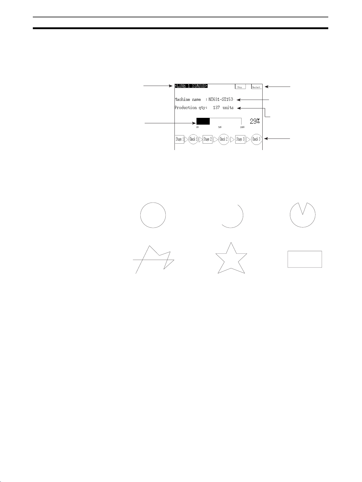
1-2-5 Displays
The NT631/NT631C can display various kinds of elements such as characters, numeric values, graphs, lamps, and touch switches, on a screen. The
screen data displayed by the NT631/NT631C are created by using the Support Tool at a personal computer.
Characters
(fixed display)
Bar graph
Characters
(character string display)
Numeric values
(numeral display)
Touch switches
Lamps
Fixed Displays Characters and various graphics (circles, circular arcs, sectors, polylines,
polygons and rectangles) whose display does not have to be changed, and
mark data, image data, and library data that has already been registered, can
be written directly onto the screen.
Circle SectorArc
Polyline Polygon Rectangle
* A continuous straight line
with up to 256 points can
be drawn.
* A polygon with up to
255 vertices can be
drawn.
Marks are graphics comprising 16 by 16 dots that can be used as characters.
They can be used as custom characters within character strings.
Image data are graphics comprising any required area of dots. They are registered in advance and as many as required can be displayed at any position on
the screen.
Windows bit map (BMP) data can be used for images.
There is a two-color mode, in which the display color and background color of
the image are specified when it is registered in a screen, and an eight-color
mode in which colors are assigned to the image in advance.
Since image data is composed of dots, it requires a large data size but offers
great powers of expression.
Library data are combinations of fixed display graphics registered as a single
graphic. They are registered in advance and as many as required can be displayed at any position on the screen.
Since it is generated by combining graphics, library data has a small data
size.
12
Page 30
Functions of the NT631/NT631C Section 1-2
Mark Image data Library data
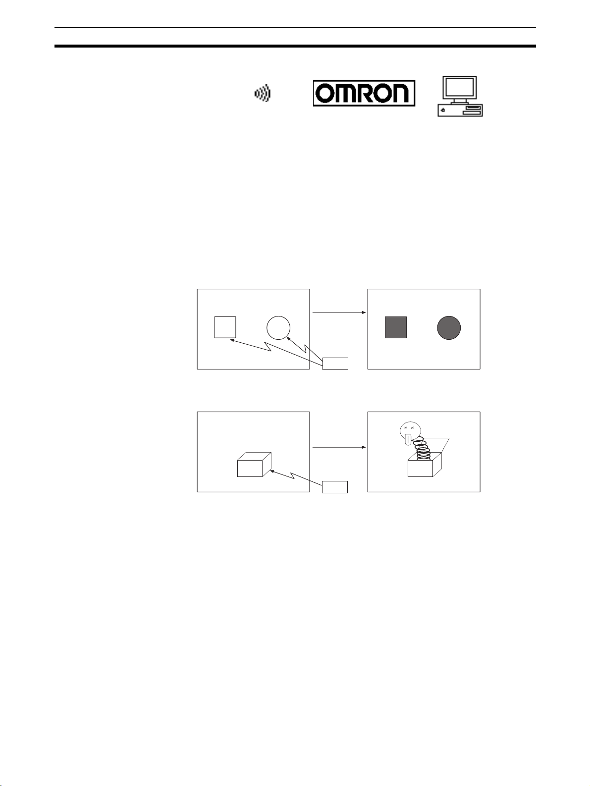
Lamps These are graphics whose display status changes in accordance with the
states of bits at the host. Squares, circles, sectors and polygons can be used
for lamps (normal (standard) lamps). In accordance with the status of the host
bit, they can be lit (displayed in reverse video) or flashed (repeated alternation
between normal and reverse video display states).
Lamps can also display different image/library data for the ON and OFF states
of the host bit (such lamps are called image/library lamps).
There are four standard lamp labels: fixed display character strings, ON/OFF
switching character strings, numeral displays, and character string displays.
When fixed display character strings or ON/OFF switching character strings
are used, several lines of labels can be displayed.
Normal (Standard) Lamps
ON
ON
Unlit state Lit state
Host
Image/Library Lamps
ON
Unlit state Lit state
Host
Touch Switches These switches can be set at any location on the screen. Pressing a touch
switch on the screen where a touch switch has been set can have the following effects:
Notification to a host bit (input notification function)
Changing the displayed screen (screen switching function)
Input of a numeric value or character string (input key function)
Copying of a numeric value or character string (copy key function)
Shifting to another numeric value or character string input field (cursor
moving key function)
Obtaining a hard copy of the screen (screen print function)
Opening / Closing a window
Moving a window
Touch switches can be made to light or flash in accordance with the status of
a host bit in the same way as lamps.
The following 8 types of display graphic can be used for touch switches:
13
Page 31
Functions of the NT631/NT631C Section 1-2
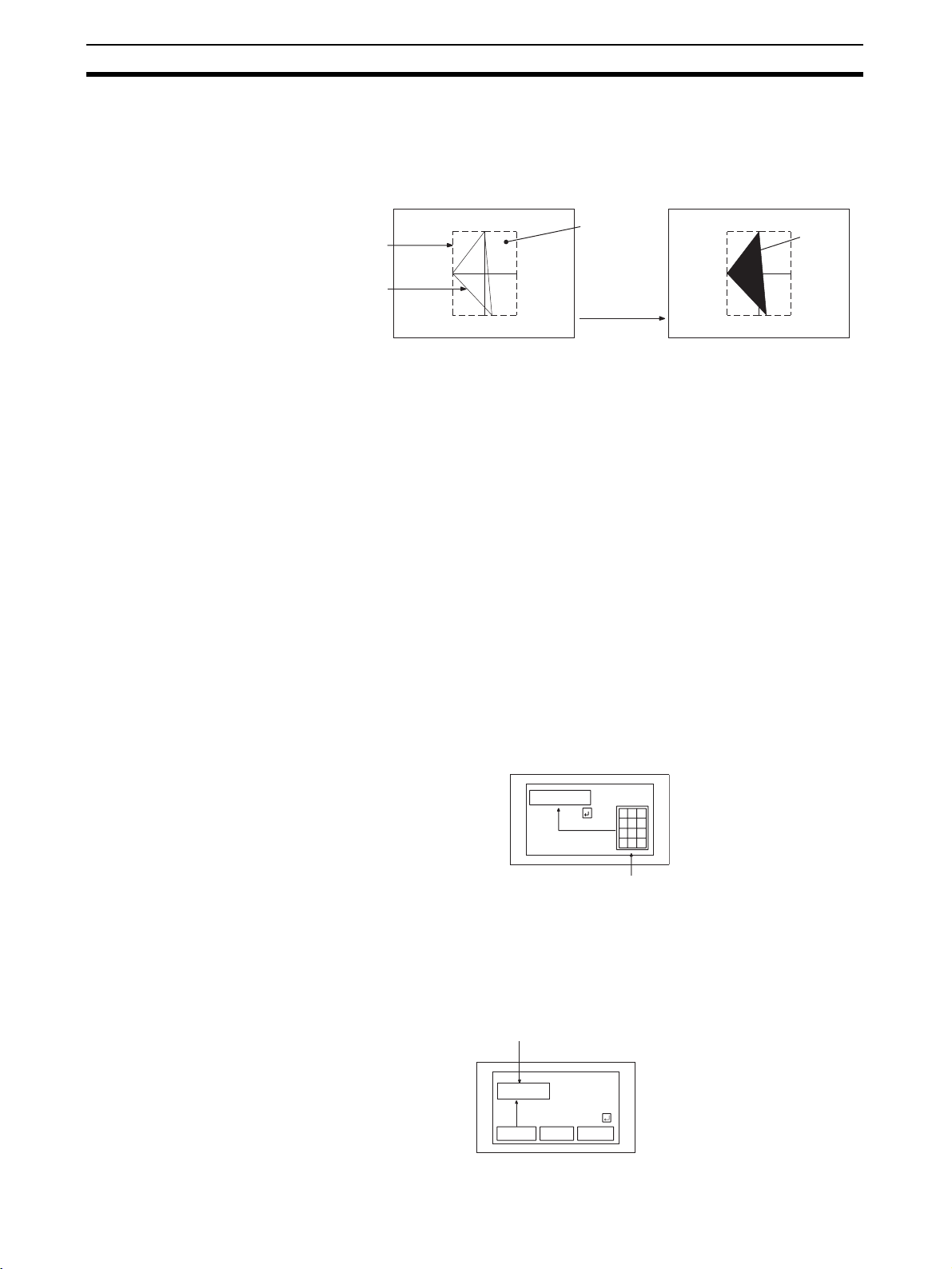
Standard, shadow, 3-dimension, no display frame, rectangle, circle, polygon, sector
When rectangle, circle, polygon, or sector is selected as the shape, the area
within which pressing of the touch switch is sensed (the touch switch area)
can be set independently of the position where the display graphic is set.
Touch
switch area
Display
frame
When this
position is
pressed...
Function executed
Shown
in
reverse
video
There are four touch-switch labels: fixed display character strings, ON/OFF
switching character strings, numeral displays, and character string displays.
When fixed display character strings or ON/OFF switching character strings
are used, several lines of labels can be displayed.
Numeral Display Numeric values stored in the numeral memory tables are displayed. The dis-
played numerals can be changed by changing the data stored in the numeral
memory tables.
Hexadecimal values can also be displayed.
When decimal values are displayed, the number of digits for the integral part
and fractional part of displayed values can be specified in advance.
String Display Character strings stored in the character string memory tables are displayed.
The displayed character strings can be changed by changing the data stored
in the character string memory tables.
Numeral Input Numeric values can be input at the PT by using touch switches. The input
numeric values can also be stored in a numeral memory table and notification
sent to the host.
Numeral inputs can be enabled and disabled from the host when an interlock
bit has been allocated.
12345678
Input
7 8 9
4 5 6
1 2 3
"
0 .
Window
String Input Character strings can be input at the PT by using touch switches, bar code
readers, etc. The input character strings can also be stored in a character
string memory table and notification sent to the host.
String inputs can be enabled and disabled from the host when an interlock bit
has been allocated.
Character string setting input field
Display
NT631C
Input
NT631C NT631
NT31C
14
Page 32

Functions of the NT631/NT631C Section 1-2
Thumbwheel Switches Numeric values can be input by incrementing or decrementing each digit with
the corresponding touch switch (+, –). The input numeric values can also be
stored in a numeral memory table and notification sent to the host.
Thumbwheel switch inputs can be enabled and disabled from the host when
an interlock bit has been allocated.
Graphs These are graphics whose display changes in accordance with the numeric
values stored in numeral memory tables. There are the following four types.
Bar graphs:
Bar graphs display the present value in a numeral memory table converted to
a percentage within the range –100% to +100% of a preset value.
60%
Analogue meter:
Analogue meters display, using a quarter, half, or full circle shape, the present
value in a numeral memory table converted to a percentage within the range –
100% to +100% of the preset value. Users can choose from moving pointer
type and filling area type displays. Users can also add graduation to the
graph.
60%
Broken line graphs:
Broken line graphs display, in an easy-to-read form, a sequence of numeral
memory table values converted to a percentage within the range –100% to
+100% of a preset value.
100%
0%
Example showing a series of
11 numeral memory table
values (with a check mark
set for the display sign)
−100%
Trend graphs:
Trend graphs display chronological changes in the value in a numeral memory
table, converting the value to a percentage within the range –100% to +100%
of a preset value. The trend graph shifts position with the passage of time.
Past data can also be recorded, and the numeral memory table can be read
(sampled) even while the trend graph is not being displayed.
The user can choose to stop sampling, restart sampling, or display past data,
by pressing touch switches.
15
Page 33

System Configuration Section 1-3
Alarm List/History The alarm list/history function displays messages in list form, or graphics
(image/library data), in accordance with changes in bit memory table statuses.
For the alarm list, a series of bit memory tables are monitored, and messages
(contents of character string memory tables) set for bit memory tables that
come ON are displayed.
For the alarm history, bit memory tables for which the history property is set
are continually monitored, and the time when they come ON and number of
times they come ON are recorded and displayed together with the message
(character string) set for the bit memory table.
The NT631/NT631C allows selection of the display order as the newest
record first or the oldest record first by memory switch setting.
The alarm list function is used to determine which bits are ON at the present
time. The alarm history function is used to determine the times at which
alarms occurred in the past and how many times alarms have occurred
Alarm List
Message (character string table No. 32)
set for bit memory table No. 14
Character string table No. 32
Image/library
data 113C
Character string table No. 50
Image/library data 1002
Character string table No. 32
Image/library data 113C
Character string table No. 54
Image/library data 1125
No.13
No.14
No.15
Bit
0
1
0
A000000
L001003
D010015
HOST
1(ON)
When the message displayed is pressed, the image/library
data (113C) set for bit memory table No. 14 is displayed.
Alarm History
Message (character string table No. 13)
set for bit memory table No. 24
Recorded data
Character string table No. 13
Character string table No. 12
Image/library
data 102B
Character string table No. 11
Image/library data 005F
Character string table No. 12
Image/library data 102A
Character string table No. 13
Image/library data 102B
No. 22
No. 23
No. 24
Bit memory table No. 24
97/12/04 11:19:20
Bit memory table No. 23
97/12/04 11:25:12
When the upper message displayed is pressed, the image/library
data (102B) set for bit memory table No. 13 is displayed.
Recipe You can set several words of numeric data at the PT in tabular format, and
write it to the host. You can also read several words of numeric data from the
host and display it on the PT screen.
1-3 System Configuration
This section shows the configuration of a system that uses an NT631/
NT631C. For details on product models, refer to Appendix J Model List
(page 281).
16
Page 34

System Configuration Section 1-3
1-3-1 Peripheral Devices That Can Be Connected
The following peripheral devices can be connected to an NT631/NT631C.
Host
Controls the NT631/NT631C as required while controlling machines and
monitoring the production line.
Host Link: CS/CJ-series, C-series, and CVM1/CV-series PLC, and SRM1
Bar code reader
Bar codes can be read
as character strings.
Printer
For printing out the
currently displayed
NT631/NT631C screen.
RS-232C cable
(max. 15 m) or
RS-422A/485 cable
(max. 500 m)
Can be connected to CPU Units, Host Link Units, and SRM1.
NT link: CS/CJ-series, C-series, and CVM1/CV-series PLC, and SRM1
Can be connected to CPU Units and SRM1. However,
Memory link: Can be connected to a personal computer, FA computer, etc.
Other companies' PLCs can also be connected.
However, connection is not possible to some models of CPU
Unit and SRM1.
connection is not possible to some models.
Personal computer
Running Windows 95/98/NT
Support Tool
Used to create screens for the
NT631/NT631C at the personal
computer and transmit them to
the NT631/NT631C, and to
make NT631/NT631C settings.
System installer
Used to change the system
program of the NT631/NT631C.
Memory unit NT631/NT631C
Can store screen data
and system program to
be read out
automatically at
startup.
Displays production line monitoring and
instructions to the operation site, and
notifies the host of the switch ON/OFF
status and numeric value inputs.
When a 1:N NT Link is being used, up
to 8 PTs can be connected to a single
PLC.
• Bar code reader (page 36)
• Recommended printers (page 36)
It is also possible to use printers that can emulate an NEC PC-PR201H
(using the NEC PC-PR201PL control protocol), and printers that comply
with one of the following EPSON control standards: ESC/P 24-J83C (color), or ESC/P 24-J82 (monochrome).
• Memory Unit (page 39)
• NT-MF261 (made by OMRON)
• Support Tool (page 35)
NT-series Support Tool Version 4.@ for Windows (Made by OMRON)
• NT-ZJCAT1-EV4 (CD-ROM version)
• System installer (page 35)
• System installer (made by OMRON)
The system installer is supplied as a standard accessory with the Support
Tool (NT-ZJCAT1-EV4).
Reference: The following optional devices are available. All of them can be used either
with NT631 or NT631C.
Anti-reflective Protective NT610C-KBA04
Sheet (5 pcs/set)
Chemical-resistant Cover NT625-KBA01
Replacement Battery 3G2A9-BAT08
17
Page 35

Communications with the Host Section 1-4
1-3-2 Connecting to the Host
The NT631/NT631C has the following two communications ports.
The serial port B is equipped with an RS-232C connector and an RS-422A/
485 terminal block (selectable by memory switch).
Serial Port A:
D-SUB 9-pin connector
For RS-232C use only (The Support Tool and bar code readers can be connected here.)
Serial Port B:
D-SUB 9-pin connector for RS-232C use only (The Support Tool and bar code
readers can be connected here) or Terminal block for RS-422A/485 use only.
The host can be connected at either of these two ports.
The connection methods for each communications method at the PT and host
sides are indicated below. Make the settings in accordance with the communications method that can be used with the PLC to be connected and the conditions at the operation site.
Reference: When using an RS-232C/422A adapter (NT-AL001) with the host link or NT
link (1:1) communications method, RS-485 cannot be used. The connection
must be made with RS-232C or RS-422A.
1-4 Communications with the Host
The NT631/NT631C is connected to the host by one of the following communications methods.
The following communications can be used to connect an OMRON PLC:
• Host Link
• 1:1 NT Link
• 1:N NT Link (standard or high-speed)
The following communications can be used to connect another companies’
PLC or FA computer:
• Communications protocol supported by the other company’s PLC
• Memory link
In all of these communications methods that can be used with NT631/
NT631C, data communications with host are by direct connection (Memory
link is, however, a quasi-direct connection).
In the following, the host link and NT link that carry out the direct connection
will be discussed. Memory link will be explained in 1-5 Communications Using
Memory Links.
1-4-1 Direct Connection Function
With the NT631/NT631C, the bits and words referring to data required for display, and those for storing input data, can be allocated to any part of the PLC
memory area.
The NT631/NT631C can directly write to and read from such allocated bits
and words to change the display status of the elements on the PT screen,
control the PT operating status, and notify the host of the status.
This function, which directly reads and writes the statuses of words and bits
without using a PLC program is called the direct connection function.
18
Page 36

Communications with the Host Section 1-4
The words and bits allocated for direct connection are called the allocated
words and allocated bits.
The direct connection function allows the data to be displayed at the NT631/
NT631C to be read from the memory area in the PLC and written to memory
tables in the NT631/NT631C. Also, the data input at the NT631/NT631C can
be written to the memory area in the PLC. The NT631/NT631C screen can be
changed in accordance with statuses in the PLC memory area, and the
NT631/NT631C’s status data can be written to the PLC’s memory area.
Features of the Direct
Connection Function
NT631/NT631C
Auxiliary relay area Timers/counters
The direct connection function has the following features.
• The bits and words referring to operating status and work instruction information and those for storing input data can be freely allocated to almost
any area of the PLC memory.
• Since the NT631/NT631C can directly refer to PLC bit and word data without using the program at the PLC, it can be connected to the PLC without
changing the PLC program which controls the currently running production line.
• The area to control and provide notification of the NT631/NT631C status,
including display screens, display/no display status, and buzzer output,
can be freely allocated to any part of the PLC data area. This means that
the PLC status can be read and controlled just by reading this area at the
PLC side, without preparing a special communications program.
The direct connection function allows the NT631/NT631C to directly read and
write almost all bits and words in the PLC and to automatically change the
NT631/NT631C screen display. This function can reduce the load on the PLC
so that its program development efficiency is improved.
PLC
DM area I/O relay area
1-4-2 Host Link
1-4-3 NT Link
The host is connected to a PT in a 1:1 connection, and the words and bits of
the host are read and displayed by host link communications. This method
can be used for connection to the majority of PLC types.
NT link is a method for high-speed communications with a PLC using the
direct connection function. The PLCs that can be connected with the NT link
are as follows.
CPM1, CPM2A, CPM2C, CQM1, CQM1H, C200HS, C200HX/HG/
HE(-Z)E, CS1G/CS1H-E(V1), CS1D, CJ1G/CJ1H/CJ1M, CVM1/CV-series
PLC (-EV1 or later version), SRM1
Besides the 1:1 NT link method, in which one PLC is connected to one PT, the
NT631/NT631C can also use the 1:N connection NT link method, which
allows a maximum of eight PTs to be connected to one PLC port.
PLCs that can be connected with the 1:N connection NT Link method are as
follows: CQM1H, C200HX/HG/HE(-Z)E, CS1G/CS1H-E(V1), CS1D, CJ1G/
CJ1H/CJ1M.
19
Page 37

Communications with the Host Section 1-4
The NT631/NT631C also supports OMRON’s high-speed 1:N NT Link that
provides faster 1:N communications. The only PLCs that support the highspeed 1:N NT Link are CS1G/CS1H PLCs of version -EV1 and higher, CS1D
PLCs, and CJ1G/CJ1H/CJ1M PLCs.
In the following sections, the term NT Link is used to refer to the NT Link communications method in general, the term 1:1 NT Link is used to refer specifically to NT Links with a 1:1 connection, and the term 1:N NT Link is used to
refer to both standard and high speed NT Links with 1:N connections. When
necessary, the standard 1:N NT Link is distinguished from the high-speed 1:N
NT Link.
Features of the NT Link The NT link has the following features.
• High-speed communications with specific types of PLCs can be executed.
The NT631/NT631C also supports OMRON’s high-speed 1:N NT Link.
• Writing in units of bits to the PLC memory area is possible.
This enables the other bits of words to which a touch switch has been allocated to be allocated for other purposes (e.g. a lamp).
However, since data is written to the DM area in word units, the other bits
of words allocated to touch switches in this area cannot be used for other
purposes.
• The NT link can be used even when the PLC is in the RUN mode. (When
the host link method is used, the NT631/NT631C switches to the monitor
mode when the PLC is in the RUN mode.)
• In the case of PTs that support the standard 1:N NT Link (NT20S, NT31,
NT31C, NT600S, NT620S, NT620C, NT625C, NT631, NT631C) up to 8
PTs can be connected to one port of the PLC and used at the same time.
Up to 8 PTs (NT31, NT31C, NT631, and NT631C) can also be connected
simultaneously when the high-speed 1:N NT Link is being used.
All of the PTs connected to a PLC port must use either the standard or
high-speed 1:N NT Link; the two communications systems cannot share a
single port.
• When using a C200HX/HG/HE(-Z)E PLC and standard 1:N NT Links, up
to three 1:N NT Link systems (i.e., 24 PTs) can be connected by installing
a Communications Board in the option slot of the CPU Unit. (Only the
standard 1:N NT Link can be used.) For details on the Communications
Board, refer to the SYSMAC Communications Board Operation Manual
(W304-E1-@).
• When using a CQM1H PLC and standard 1:N NT Links, multiple 1:N NT
Link systems can be connected by installing Serial Communications
Boards in the Inner Board slots. For details on the Serial Communications
Board, refer to the CQM1H Serial Communications Board Operation Man-
ual (W365-E1-@).
• Multiple 1:N NT Link systems (standard or high-speed) can be connected
by installing a Communications Board in the Inner Board slot of the CPU
Unit for a CS1G/H/D PLC or installing a Serial Communications Unit on
the Backplane for a CS1G/H/D or a CJ1G/M/H PLC. For details on the
Communications Board/Communications Unit, refer to the CS/CJ-series
Serial Communications Board/Unit Operation Manual (W336-E1-@).
• If the PLC supports the Programming Console function, the NT631/
NT631C can be used as a Programming Console.
• If the PLC supports the Device Monitor function, the NT631/NT631C can
be used to change the PLC’s operating mode and read/change data in the
PLC’s memory areas.
20
Page 38
Communications Using Memory Links Section 1-5
The NT link is compatible with the host link. The NT631/NT631C screen data
and PLC programs used with the host link direct connection method can be
used with the NT link method as they are.
1-4-4 Connecting to Other Companies’ PLCs
Installing a system program for multi-venders by using a specific system
installer enables the NT631/NT631C to be connected to the PLCs of other
models in direct connection. This system installer is supplied with the Support
Tool (NT-ZJCAT1-EV4).
Compatible PLC The NT631/NT631C can be connected to the following model PLCs.
• Mitsubishi A-series programmable controller (computer link module)
• Mitsubishi FX-series programmable controller
• SLC 500 Series by Allen-Bradley
• 90-20 and 90-30 Series by GE Fanuc
• S7-300 and S7-400 Series by Siemens
For details on the procedure for connecting to other model PLCs, refer to the
PLC Connection Manual or NT31/631 Multi Vendor Connection Manual.
1-5 Communications Using Memory Links
1-5-1 Memory Link
In this section, a communications method other than the direct connection,
called the memory link, is discussed.
Memory link is a method to send and receive data between a personal computer or a FA computer and the NT631/NT631C by using RS-232C/422A
communications.
In memory link, there is an area called PT Memory, as shown below, inside
the NT631/NT631C, and this area is treated as a virtual area on the PLC. This
allows PT memory and the display elements of the NT631/NT631C to make a
quasi-direct connection. By sending a command for the memory link, the host
can make the NT631/NT631C execute processes through PT memory. Frequently used commands are kept handy for read and write tasks of the
numeral memory table, character-string memory table, and bit memory table.
PT
Numeral
memory
table
Lamp
Direct connection
PT memory
RS-232C/422A
communications
In the memory link method, the only difference is that the NT631/NT631C
finds its communications target inside instead of outside. In the memory link
method, therefore, change of the target is all that is needed to be capable of
using the exact screen data that is acquired by the direct connection. (With
the NT631/NT631C, the Support Tool must be used to convert the data to
screen data for the memory link.)
When compared to the direct connection of the host link or NT link methods,
the memory link method has some restrictions regarding the use of some
functions, as described below.
21
Page 39

Communications Using Memory Links Section 1-5
• The Programming Console and Device Monitor functions cannot be used.
• The following strobes of PT status notify bits do not turn ON (pages 7 to
27).
• Screen switching strobe
• Numerals input strobe
• Character-string input strobe
• The usable area for allocation is the PT memory only.
1-5-2 Comparison between Direct Connection and Memory Link
The major differences between the direct connection and the memory link are
as follows:
1,2,3... 1. In the memory link method, the communications with the host should be
carried out by using commands. Compared to the ordinal direct connection, which can be used requiring almost no programs, the memory link
method requires a program that is necessary for interchange of commands.
This, however, gives advantages to the memory link method by using a
large variety of functions available in the direct connections from major
models such as a personal computer and a FA computer equipped with
RS-232C/RS-422A communications means, allowing the PT to be suited
for larger usage.
2. Actual PLCs have many kinds of areas, where as PT memory is a single
area with only one kind. When creating screen data by using the memory
link methods, it is always necessary to allocate display parts in the PT
memory.
For communications between the host and the PT by the memory link method
and for handling screen display elements, refer to the NT31/NT31C/NT631/
NT631C Programmable Terminal Reference Manual.
1-5-3 Memory Link Online Transfer Function
When memory link communications are being used, the NT631/NT631C can
be switched to Transmit mode from the host even if the NT631/NT631C is
operating and screen data can be written. (The NT631/NT631C can be
returned to RUN mode after the screen data is written.)
The memory link online transfer function can be used to replace screen data
at a fixed time each day or replace screen data with maintenance screen data
for maintenance.
For more details on the memory link online transfer function, refer to informa-
tion on the memory link online transfer function in the NT31/NT31C/NT631/
NT631C Programmable Terminal Reference Manual.
22
Page 40

Before Operating Section 1-6
1-6 Before Operating
Follow the procedure given below to start the system of the NT631/NT631C.
Host
Set the host settings.
• For the host link, refer to
pages 48 and 94, and the
manuals for the Host Link
Unit and Programming
Devices.
• For the NT link (1:1), refer
to pages 61 and 106.
• For the NT link (1:N), refer
to pages 65 and 108.
• For the high-speed NT
link (1:N), refer to pages
70 and 112.
• For the Memory link, refer
to pages 73 and 114.
Connect to the
NT631/NT631C.
Create the host program.
NT631/NT631C
Install the PT in the
operation panel.
(page 32)
Connect the power supply.
(page 33)
Install the system program.
(Refer to page 145 and the
Support Tool manual)
Make the settings in the
system installer mode.
(page 144)
Transmit the screen data.
Set the memory switches.
(page 152)
Connect to the host.
When RS-232C used at the PT: refer to section 4
When RS-422A/485 used at the PT: refer to section 5
Confirm the settings and
check communications.
*1
*2
Install the Support
Tool at the computer.
Create the screens.
Support Tool
(Refer to the manual for
the Support Tool.)
(Refer to the NT31/NT31C/NT631/NT631C
Programmable Terminal Reference Manual
and the Support Tool Operation Manual.)
(page 149)
Start operation.
*1
System program installation is only done in special circumstances, for
example when changing the system program, or to recover the original status of the installed program. This operation is not normally necessary.
When using other PLC models (sequencers), however, it is necessary to
install specific system programs.
*2
Display of the system menu, and all change operations, can be inhibited.
This enables you to prevent the accidental deletion or alteration of screens
and settings.
Reference: • For the system program, use the NT631/NT631C system program sup-
plied as an accessory with the NT-series Support Tool (NT-ZJCAT1-EV4).
• For the Support Tool, use NT-series Support Tool for Windows (Ver. 4.@).
Refer to the following manuals for the devices and software.
Device or Software Manual Title Manual Number
NT31/NT31C, NT631/
NT631C
System Installer NT-series Support Tool for Windows (Ver. 4.@) Operation Manual V061-E1-@
Support Tool NT-series Support Tool for Windows (Ver. 4.@) Operation Manual V061-E1-@
Reference Manual V064-E1-1
23
Page 41

Before Operating Section 1-6
Device or Software Manual Title Manual Number
PLCs SYSMAC CPM1 Operation Manual W262-E1-@
SYSMAC CPM1A Operation Manual W317-E1-@
SYSMAC CPM2A Operation Manual W352-E1-@
SYSMAC CPM1/CPM1A/CAM2A/CPM2C/SRM1(-V2)
Programmable Controllers Programming Manual
SYSMAC CPM2C Operation Manual W356-E1-@
SYSMAC C200H Operation Manual (for CPU01/03/11) (programming) W130-E1-@
SYSMAC C200H Operation Manual (for CPU21/23/31) (programming) W217-E1-@
SYSMAC C200HS Installation Guide W236-E1-@
SYSMAC C200HS Operation Manual (programming) W235-E1-@
SYSMAC C200HX/HG/HE-ZE Installation Guide W302-E1-@
SYSMAC C200HX/HG/HE Programming Manual W303-E1-@
SYSMAC C200HX/HG/HE-Z Programming Manual W322-E1-@
SYSMAC C1000H/C2000H Operation Manual (programming) W140-E1-@
SYSMAC CQM1 Programming Manual W228-E1-@
SYSMAC CQM1H Operation Manual W363-E1-@
SYSMAC CVM1/CV500/CV1000/CV2000 Operation Manual:
Ladder Diagrams
SYSMAC CS Series Programmable Controllers Operation Manual W339-E1-@
SYSMAC CJ Series Programmable Controllers Operation Manual W393-E1-@
SYSMAC CS Series, CJ Series, NSJ Series Programmable Controllers
Programming Manual
SYSMAC CS Series, CJ Series, NSJ Series Programmable Controllers
Operation Manual
SYSMAC CS/CJ Series Programming Consoles Operation Manual W341-E1-@
SYSMAC CS/CJ/CP Series, NSJ Series Communications Commands
Reference Manual
SYSMAC CS/CJ Series Serial Communications Boards,
Serial Communications Units Operation Manual
SYSMAC CQM1H Series Serial Communications Board Operation
Manual
CompoBus Master
Control Unit
Programming Devices SYSMAC Support Software Operation Manual: C-series PLCs W248-E1-@
Host Link Units and
Serial Communications
Boards
SRM1 Operation Manual W318-E1-@
SYSMAC Support Software Operation Manual: CVM1 PLCs W249-E1-@
SYSMAC CPT User Manual and Quick Start Guide W332-E1-@
CX-Programmer Operation Manual W446-E1-@
SYSMAC C-series Host Link Unit Operation Manual W143-E1-@
SYSMAC CVM1/CV-series Host Link Operation Manual W205-E1-@
SYSMAC C200HW-COM01 C200HW-COM02-V1 to C200HW-COM06EV1 Serial Communications Board Operation Manual
W353-E1-@
W202-E1-@
W394-E1-@
W340-E1-@
W342-E1-@
W336-E1-@
W365-E1-@
W333-E1-@
W304-E1-@
24
Page 42

SECTION 2
Preparing for Connection
This section describes the connection methods that are possible with the PT, and the functions of the parts of PT, as the
required knowledge before connecting to the host and to the peripheral devices.
2-1 Method for Connection to the Host . . . . . . . . . . . . . . . . . . . . . . . . . . . . . . . . 26
2-2 Names and Functions of Parts . . . . . . . . . . . . . . . . . . . . . . . . . . . . . . . . . . . . 29
25
Page 43

Method for Connection to the Host Section 2-1
2-1 Method for Connection to the Host
This section describes the methods for connection to the host used with the
NT631/NT631C, and the relationship between the connection method and the
communications method.
NT631/NT631C Communications Ports and Communications Methods
The NT631/NT631C has two communications ports. Their uses are indicated
in the table below.
Communications Port Usable Communications
Methods
Serial port A Host link
NT Link (1:1)
NT Link (1:N) (See note.)
Memory link
(Support Tool connection)
(bar code reader input function)
Serial port BConnector Host link
NT Link (1:1)
NT Link (1:N) (See note.)
Memory link
Te r mi n al
block
Host link
NT Link (1:1)
NT Link (1:N) (See note.)
Communications Type
RS-232C
RS-232C
(select between con-
nector and terminal
block)
RS-422A/485
(select between con-
nector and terminal
block)
Note There are two NT Link (1:N) communications rates: standard and high-speed.
Communications Methods That Can Be Used with the Host
The following communications methods can be used with the hosts that can
be connected to the NT631/NT631C.
• RS-232C
• RS-422A
•RS-485
The communications types that are actually supported differ depending on the
host. For details, refer to SECTION 4 Connecting to the Host from the RS-
232C Port and SECTION 5 Connecting to the Host from the RS-422A/485
Por t.
Converting the Communications Type with an RS-232C/RS-422A Adapter
The following communications type conversions are possible by using an RS232C/RS-422A adapter (NT-AL001, made by OMRON).
• RS-232C
• RS-232C
⇔ RS-422A
⇔ RS-485
26
Page 44

Method for Connection to the Host Section 2-1
(
)
Combinations of Communications Method and Connection Method
The connection methods that can be used depending on the communications
method used and the communications type for communications between the
NT631/NT631C and the host are indicated in the table below.
Communications Type at
PT
RS-232C RS-232C ❍❍❍❍ page 73
RS-422A RS-232C ❍❍❍❍ page 82
Communications Type at
Host
Usable Connection Method Usable Communications
Direct 1:1 connection
PT
RS-232C (max. 15 m)
1:1 connection via a convertor unit
max. 500 m
Convertor unit
(NT-AL001)
RS-232C
(max. 2 m)
PT Host
RS-422A
1:N connection via a convertor unit
PT
RS-422A
(total length 500 m)
Convertor unit
(NT-AL001)
RS-232C
(max. 2 m)
Host
Host
Method
Details
Host
link
NT
Link
(1:1)
NT
Link
(1:N)
Mem-
ory
link
××❍ × page 86
RS-422A ❍❍❍❍ page 115
Direct 1:1 connection
PT Host
RS-422A (max. 500 m)
1:N connection
PT
RS-422A (total length 500 m)
××❍ × page 119
Host
❍: Connection possible
×: Connection not possible
27
Page 45
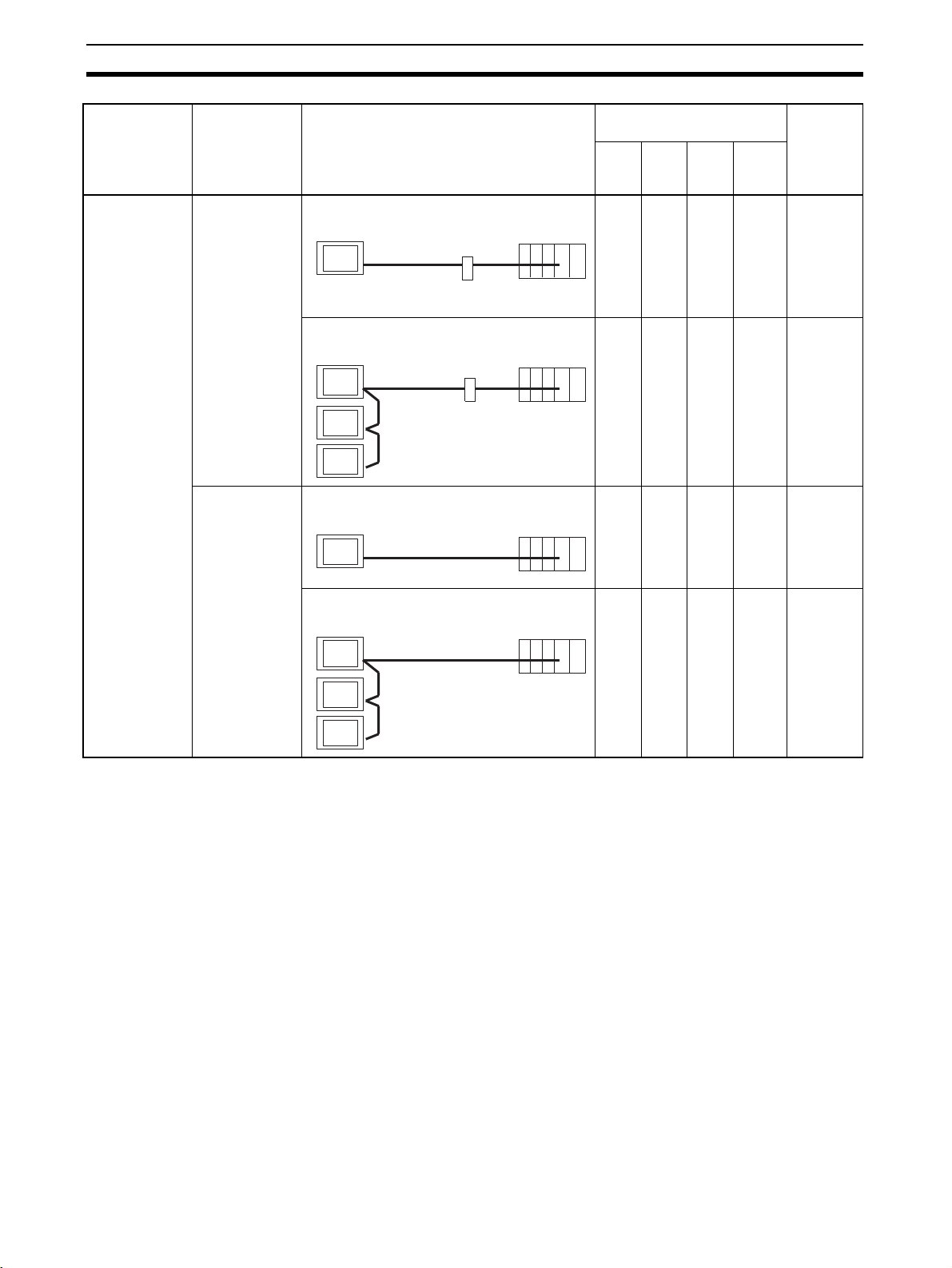
Method for Connection to the Host Section 2-1
(
)
Communica-
tions Type at
PT
RS-485 RS-232C ××❍ × page 82
Communica-
tions Type at
Host
Usable Connection Method Usable Communications
Method
Host
link
NT
Link
(1:1)
NT
Link
(1:N)
Mem-
ory
link
Details
1:1 connection via a convertor unit
PT
RS-485
(max. 500 m)
1:N connection via a convertor unit
PT
RS-485
(total length 500 m)
RS-485 ××❍ × page 118
Direct 1:1 connection
PT
RS-485
1:N connection
PT
Convertor unit
(NT-AL001)
Convertor unit
(NT-AL001)
max. 500 m
RS-232C
(max. 2 m)
RS-232C
(max. 2 m)
Host
××❍ × page 86
Host
Host
××❍ × page 121
Host
RS-485 (total length 500 m)
❍: Connection possible ×: Connection not possible
• The RS-232C/RS-422A adapter (NT-AL001) requires +5 V, 150 mA at pin
6 of the RS-232C connector. Check the signals of the RS-232C connector
at the host.
• +5 V is not output from serial port B of the NT631/NT631C. When connecting an NT-AL001 at serial port B, a separate power supply is required
for the NT-AL001.
• The cable of an NT-AL001 cannot be connected or disconnected while the
power is ON. Always connect or disconnect the cable while the power
supply from the RS-232C cable is OFF (while the host power supply is
OFF).
• NT Link (1:N) connection is possible even when RS-232C is used at the
NT631/NT631C side for communications with the host, but in this case
one NT-AL001 Adapter is required for each NT631/NT631C. In this case,
it is convenient to use serial port A of the NT631/NT631C. +5 V is not output from serial port B.
28
Page 46
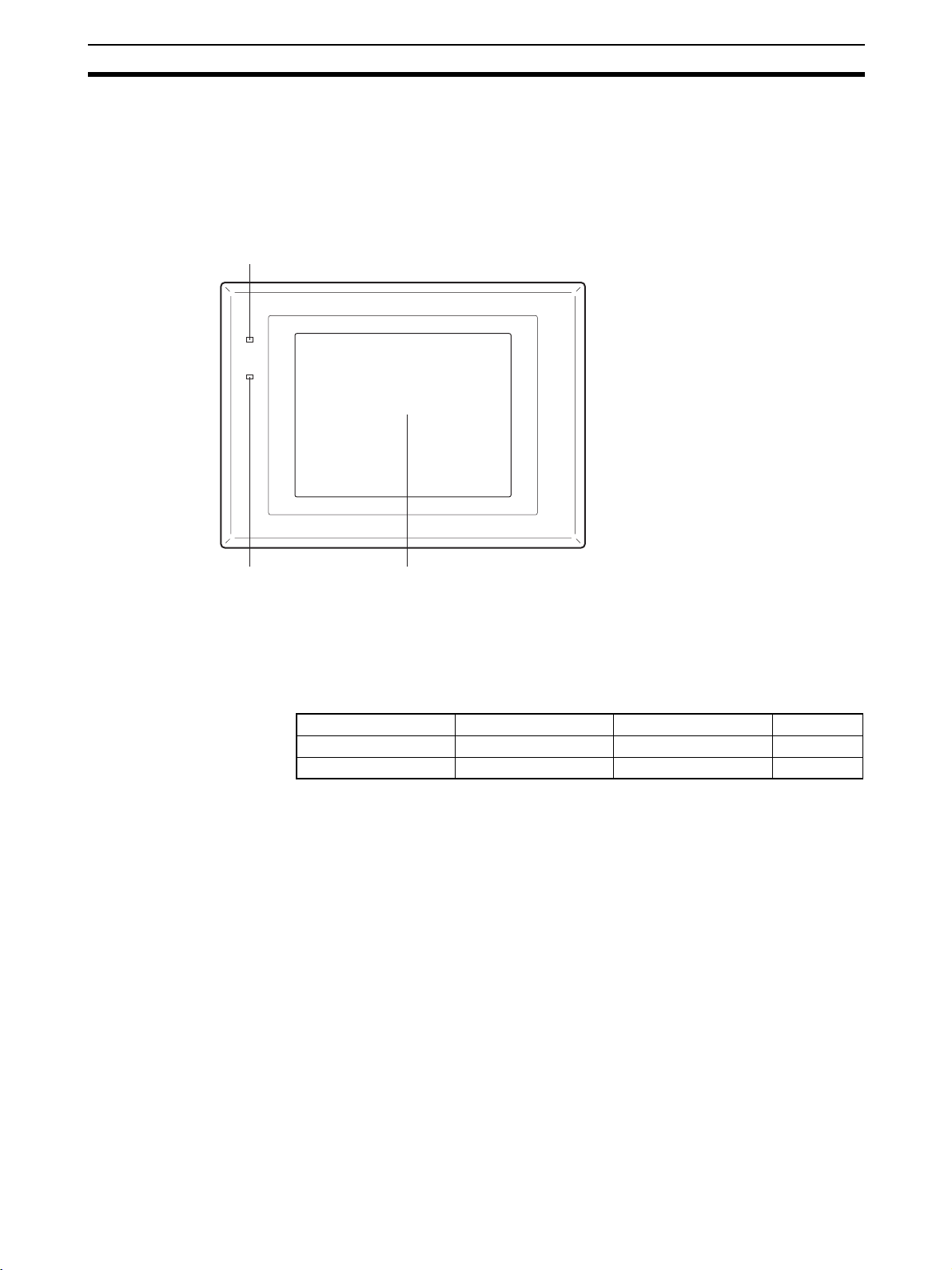
Names and Functions of Parts Section 2-2
2-2 Names and Functions of Parts
Before starting operation, the names and functions of the parts of the NT631/
NT631C are described here as a confirmation. A method of hardware settings
is also described.
Front View
POWER LED
Lit in green when the power is supplied.
POWER
RUN
RUN LED Display
• Lit in green while the
unit is in the RUN mode.
• Lit in orange or red when
the battery is low (orange
in the RUN mode, red in
other modes).
Depending on the model, different display types are used.
• NT631-ST211@-EV2: Monochrome EL display
• NT631C-ST141@-EV2: STN color LCD display with backlight
• NT631C-ST151/152@-EV2: TFT color LCD high intensity display with backlight
The whole area of the screen is a touch panel which works as an input device.
Reference: The NT631/NT631C comes in two body colors.
NT631 (EL) NT631C (STN) NT631C (TFT) Body Color
NT631-ST211-EV2 NT631C-ST141-EV2 NT631C-ST153-EV3 Beige
NT631-ST211B-EV2 NT631C-ST141B-EV2 NT631C-ST153B-EV3 Black
29
Page 47
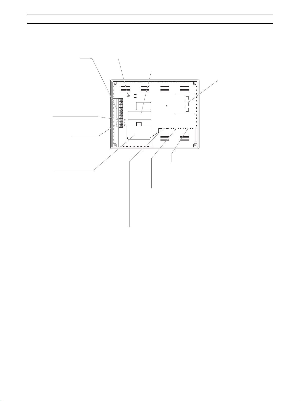
Names and Functions of Parts Section 2-2
Rear View
Reset switch (inside the cover)
Used to initializes all the statuses of the NT631/NT631C.
However, registered data such as screen data, and memory
Serial port B terminal block
Connect the cable for RS422A/485 connection to the host
here. Depending on the setting
made at the NT631/NT631C
system menu, communications
through RS-422A/485 are
available. It is not possible to use
this terminal block and the serial
port B connector (9-pin) at the
same time.
GR terminal
Grounding terminal to prevent
malfunction due to noise.
Power input terminals
Connect the power to
the NT631/NT631C at
these terminals.
Battery cover
The battery is secured
underneath this cover.
switch settings, retain their statuses before initialization.
Warning label
RESET
RDA
TRM
RDB
SDA
SDB
RSA
RSB
24V
+DC
PRINTER PORT B PORT A
Serial port A connector
Connect the cable for connection to the host or
Support Tool here. A bar code reader can also
be connected here. This is a 9-pin connector for
RS-232C use only.
Expansion interface connector
(under the label)
When using an expansion
interface unit such as a
memory unit, peel off the label
and connect it here.
Serial port B connector
Connect the cable for RS-232C connection to the host here.
Depending on the setting made at the NT631/NT631C
system menu, communications through RS-232C are
available. This is a 9-pin connector for RS-232C use only.It is
not possible to use this connector and the serial port B
terminal block at the same time.
Printer connector
Connect the printer cable here.
Output conforms to Centronics
specifications.
Note Confirm system safety before turning the power ON/OFF or resetting.
30
Page 48

SECTION 3
Hardware Settings and Connections
This section describes the settings of the NT631/NT631C and methods for connection to peripheral devices.
For details on the method for connection to the host, refer to SECTION 4 Connecting to the Host from the RS-232C
Port or SECTION 5 Connecting to the Host from the RS-422A/485 Port.
3-1 Installation . . . . . . . . . . . . . . . . . . . . . . . . . . . . . . . . . . . . . . . . . . . . . . . . . . . 32
3-1-1 Installation Environment . . . . . . . . . . . . . . . . . . . . . . . . . . . . . . . . . 32
3-1-2 Installation in the Operation Panel . . . . . . . . . . . . . . . . . . . . . . . . . . 32
3-1-3 Power Supply Connection . . . . . . . . . . . . . . . . . . . . . . . . . . . . . . . . 33
3-1-4 Grounding . . . . . . . . . . . . . . . . . . . . . . . . . . . . . . . . . . . . . . . . . . . . 34
3-2 Connecting to the Support Tool . . . . . . . . . . . . . . . . . . . . . . . . . . . . . . . . . . . 35
3-3 Connecting a Printer. . . . . . . . . . . . . . . . . . . . . . . . . . . . . . . . . . . . . . . . . . . . 36
3-3-1 Connection Method . . . . . . . . . . . . . . . . . . . . . . . . . . . . . . . . . . . . . 36
3-4 Connecting a Bar Code Reader . . . . . . . . . . . . . . . . . . . . . . . . . . . . . . . . . . . 36
3-4-1 Connection Method . . . . . . . . . . . . . . . . . . . . . . . . . . . . . . . . . . . . . 37
3-4-2 Setting a Bar Code Reader . . . . . . . . . . . . . . . . . . . . . . . . . . . . . . . . 37
3-4-3 Data Format . . . . . . . . . . . . . . . . . . . . . . . . . . . . . . . . . . . . . . . . . . . 38
3-5 Using a Memory Unit. . . . . . . . . . . . . . . . . . . . . . . . . . . . . . . . . . . . . . . . . . . 39
3-5-1 Installation Method . . . . . . . . . . . . . . . . . . . . . . . . . . . . . . . . . . . . . 40
3-5-2 Method of Use . . . . . . . . . . . . . . . . . . . . . . . . . . . . . . . . . . . . . . . . . 40
31
Page 49

Installation Section 3-1
Note On unpacking the NT631/NT631C and peripheral devices, check their exter-
nal appearance and confirm that there is no damage. Also confirm that there
is no abnormal noise on shaking the PT lightly.
3-1 Installation
Install the NT631/NT631C in the operation panel and connect the power to
the NT631/NT631C as described below.
3-1-1 Installation Environment
Observe the following points when installing the PT in an operation panel.
Note 1. Do not install the PT at sites subject to the following conditions.
• Severe temperature variations
• Temperatures or humidities outside the ranges stated in the specifications
• High humidity, condensation
• Splashing chemical agents
• Severe oil splashing
• Corrosive or flammable gases
• Strong vibrations or shocks
• Direct exposure to wind and rain (outdoor sites)
• Strong ultra-violet irradiation
2. Take adequate measures to ensure shielding if the PT is used at a location
subject to any of the following conditions.
• Static electricity, or noise from other equipment
• Strong electromagnetic fields
• Nearby power cables
• Potential exposure to radioactivity
3-1-2 Installation in the Operation Panel
The NT631/NT631C is mounted in an operation panel by embedding it in the
panel.
Use the panel fittings and tool (Phillips screwdriver) included in the product
package and follow the procedure below.
1,2,3... 1. Open a hole of the dimensions shown below in the panel and install the
NT631/NT631C from the front side of the panel.
+ 0.5 mm
238
0 mm
+ 0.5 mm
303
0 mm
2. Attach the panel fittings at the following positions shown below, from the
rear of the NT631/NT631C.
Fit the hook of the fitting in the square hole in the body and tighten the
screw with the Phillips head screwdriver while lightly pulling the fitting.
32
Page 50

Installation Section 3-1
p
y
Fittings at the two (*) positions are not necessary if you do not need it dust
proof and waterproof.
(:)
RESET
RDA
TRM
RDB
SDA
SDB
CSA
CSB
24V
+DC
Note 1. During work at the panel, take care to ensure that no metal scraps enter
the PT.
2. The thickness of applicable operation panel is 1.6 mm to 4.8 mm. All fittings must be tightened uniformly to a torque of 0.5 to 0.6 N
ensure water- and dust-resistance. Front sheet of NT631/NT631C may be
warped if the tightening is too strong or not uniformity. The panel must not
be soiled or warped, and must be able to support an installation that will
remain secure and strong.
PRINTER PORT B PORT A
(:)
⋅m in order to
3-1-3 Power Supply Connection
Connect a 24 VDC power supply to the power input terminals.
Note 1. Depending on how the power is switched ON/OFF, the entire system may
stop. Follow the correct procedure when switching the power ON/OFF.
2. Carefully check the wiring before switching ON the power.
3. Do not connect AC power to the DC terminals.
4. Use DC power supplies with low voltage fluctuation.
5. Do not perform a dielectric strength test.
6. If complying with EC directives (low voltage directives), the following points
must be noted (compliance with EC directives):
a. Use a power supply with reinforced insulation.
b. When installing NT631-ST211(B)-EV2 on the ultimate system, the
rear of the NT631 must be placed within an enclosure to restrict the
operators’ use only to the front panel.
7. When using NT631-ST211(B)-EV2, warm-up time of the power supply
must be 200 ms or less. If longer than this, NT631 may not boot up.
24 VDC
Breaker
24 VDC
ower suppl
33
Page 51
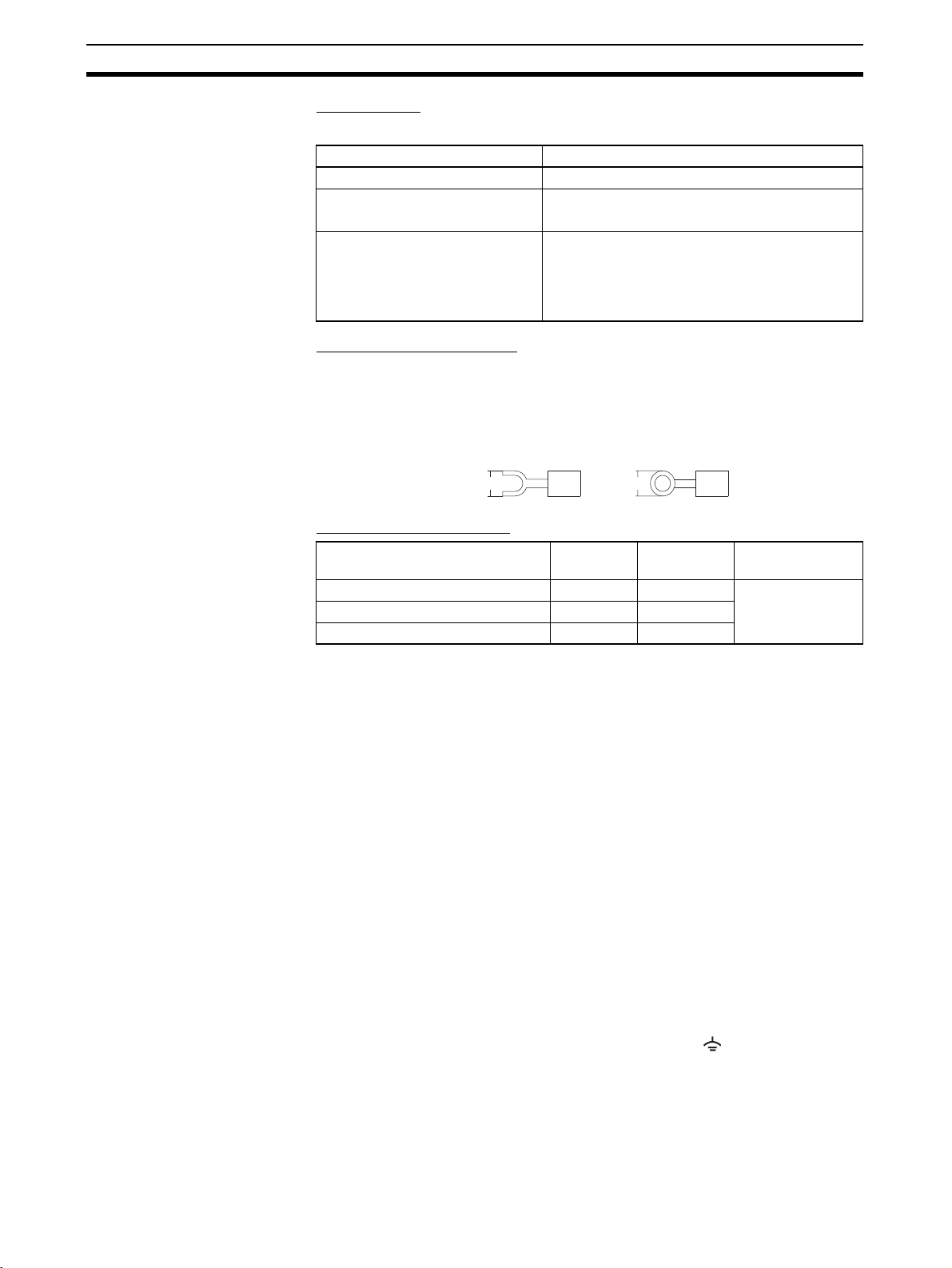
Installation Section 3-1
Power Supply
The applicable power supply specifications are as follows.
Item Value
Power supply 24 VDC
Allowable power supply voltage
fluctuation range
Power supply voltage capacity NT631-ST211 (B)-EV2:
Parts Used for Connection
20.4 to 26.4 VDC (24 VDC –15% to +10%)
30 W or more (Power supply warm-up time
within 200 ms.)
NT631C-ST141 (B) /ST153 (B)-EV3:
18 W or more
Note For the connection to the power supply terminal block, twisted wires of 2 mm
or greater cross sectional area and M3.5 size crimp terminals must be used.
Tighten the screws on the terminal block to a torque of 0.8 N
Fork type Round type
7 mm max. 7 mm max.
⋅m.
Recommended Terminals
Maker Type
(fork type)
Japan Solderless Terminal MFG 2-YS3A 2-3.5
Fuji Terminal 2-YAS3.5 V2-S3.5
Nichifu Terminal 2Y-3.5 2-3.5
Type
(round type)
Applicable Wire
(stranded wire)
2.0 to 2.63 mm
2
Note Conformance to Shipbuilding Standard
• Cover the entire PT with electromagnetic shielding, and ground the electromagnetic shielding to the control panel with copper tape or other electrically conductive tape.
Recommended electromagnetic shielding: E09F100 or E09R13502P
Manufacturer: Seiwa Electric MFG, Co., Ltd.
• Use gaskets or other materials to completely shield all openings and
other gaps in the control panel.
• Use copper tape or other electrically conductive tape to shield gaps
between the cutout and the PT before securing the PT in place.
• To suppress noise terminal voltage, perform installation under the following conditions. It is recommended to use the following product for the DC
power supply.
Recommended Power Supply model: S82K-03024
Manufacturer: OMRON
2
3-1-4 Grounding
34
The NT631/NT631C has a functional ground terminal ( ).
Carry out wiring under the following conditions.
Page 52

Connecting to the Support Tool Section 3-2
t
1,2,3... 1. In cases where there is a potential difference between the grounds of the
NT631/NT631C and the host, ground as shown in Fig. If there is some distance between the NT631/NT631C and host and grounding at a single
point is difficult, do not connect the functional ground terminal ( ) of the
NT631/NT631C.
2. If the NT631/NT631C is installed in the same panel as equipment that generates noise, such as a motor or inverter, do not ground the functional
ground terminal ( ) of the NT631/NT631C.
NT631/
NT631C
Note Carry out grounding correctly in order to prevent operating errors due to
noise.
3-2 Connecting to the Support Tool
In order to install the system program in the NT631/NT631C, or to transmit
screen data created with the Support Tool to the NT631/NT631C, the NT631/
NT631C must be connected to a personal computer with an RS-232C cable.
The NT631/NT631C connects the RS-232C cable from a personal computer
at serial port A. When the host is connected at serial port B, the connection
with the host can be maintained as it is while the NT631/NT631C is connected
to the RS-232C cable from a personal computer.
However, when a bar code reader is being used, it must be disconnected, so
that the RS-232C cable can be connected, since they both use serial port A.
RESET
RDA
TRM
RDB
SDA
SDB
CSA
CSB
24V
PRINTER PORT B PORT A
+DC
Host
Grounding at a single poin
Serial port A
(RS-232C, 9-pin)
Communications Conditions
The communications conditions are automatically set when the system
installer and Support Tool are started.
Recommended Connector Cable
Use the cable indicated below.
• CV500-CN228 (length: 2 m), made by OMRON
(D-SUB 9-pin, male
⇔ D-SUB 25-pin, male)
• XW2Z-S001 (conversion cable), made by OMRON
(D-SUB 25-pin, female
⇔ half pitch 14-pin, male)
• XW2Z-S002 (length: 2 m), made by OMRON
(D-SUB 9-pin, male
⇔ D-SUB 9-pin, female)
For details on making a connector cable, refer to Appendix F Making the
Cable for Connecting a PLC.
35
Page 53
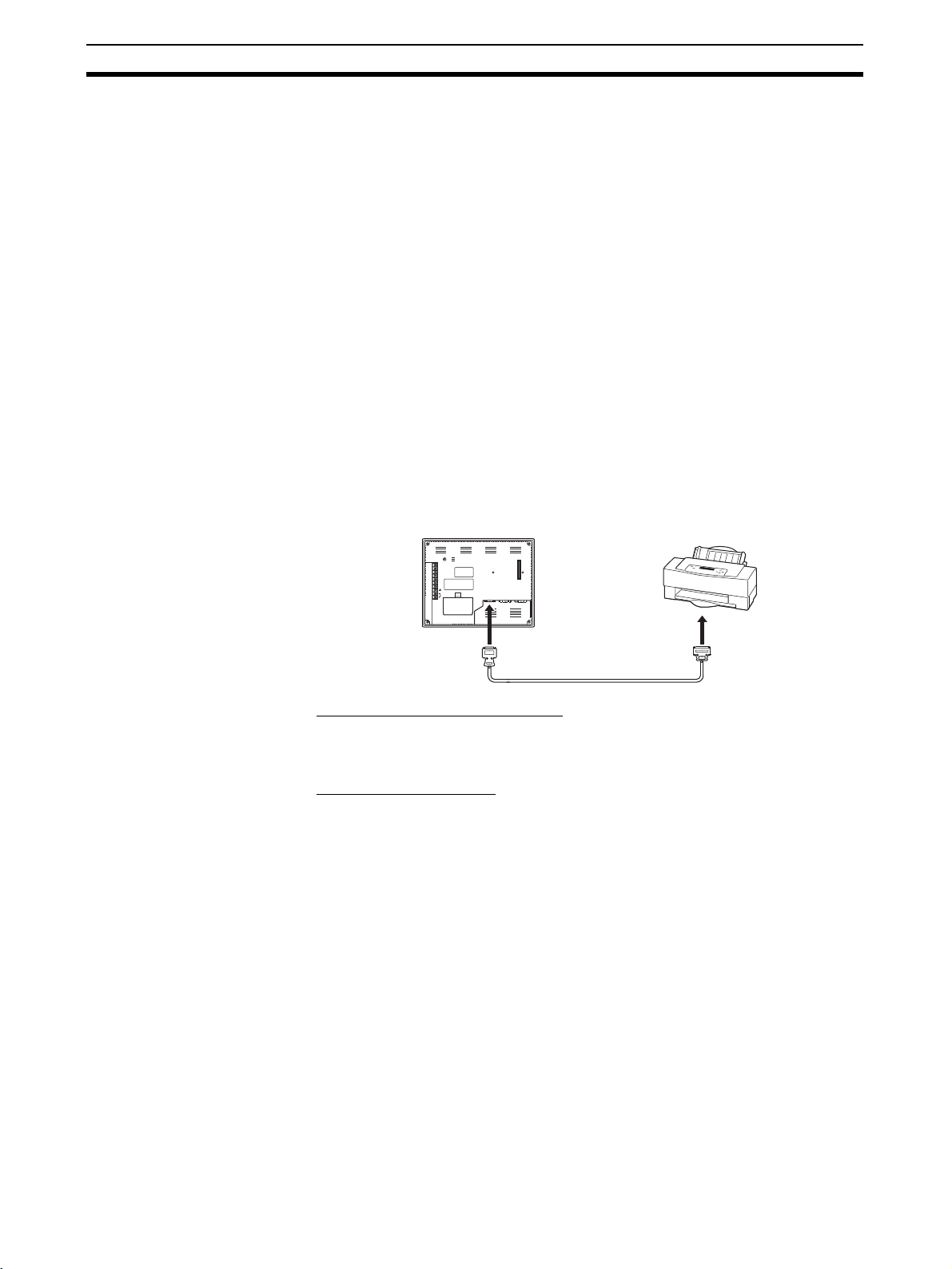
Connecting a Printer Section 3-3
3-3 Connecting a Printer
Connecting a printer to the NT631/NT631C enables printing of hard copies of
the currently displayed screen (printing of screen images), and, by system
menu operations, printing of the screen display history and alarm history.
The following types of data can be printed, depending on the printer connected to the NT631/NT631C. For details, refer to the pages cited.
• Hard copies of the screen (Refer to information on printing data and
checking the printer status in the NT31/NT31C/NT631/NT631C Program-
mable Terminal Reference Manual.)
• Screen display history record data (page 194)
• Alarm history record data (page 196)
3-3-1 Connection Method
Connect the printer to the NT631/NT631C with a Centronics cable, as shown
below. The length of the cable should not exceed 1.5 m.
Reference:
If the connector cable is connected or disconnected while the power to the
printer is on, the NT631/NT631C may malfunction. Always turn off the power
to the printer before connecting or disconnecting the cable.
RESET
RDA
TRM
RDB
SDA
SDB
CSA
CSB
24V
PRINTER PORT B PORT A
+DC
Recommended Connector Cable
The following connection cables are recommended.
NT-CNT121 (1.5 m, 20-pin to 36-pin), made by OMRON
Recommended Printers
When using a printer, use one that can emulate an NEC PC-PR201H (using the NEC PC-PR201PL control protocol) or complies with one of the following EPSON control standards: ESC/P 24-J83C (color), or ESC/P 24J82 (monochrome).
When using a monochrome printer with an NT631C, set Tone printing with
the NT631C memory switches (page 169).
3-4 Connecting a Bar Code Reader
Connecting a bar code reader to the NT631/NT631C enables bar code data
to read as character strings into character string input fields, and set in character string memory tables.
In order to use a bar code reader, the Comm. A Method memory switch must
be set to Bar-Code Reader.
For details on the method for inputting character strings with a bar code
reader, refer to 3-7 Input of Numeric values and Character Strings in the
NT31/NT31C/NT631/NT631C Programmable Terminal Reference Manual.
36
Page 54
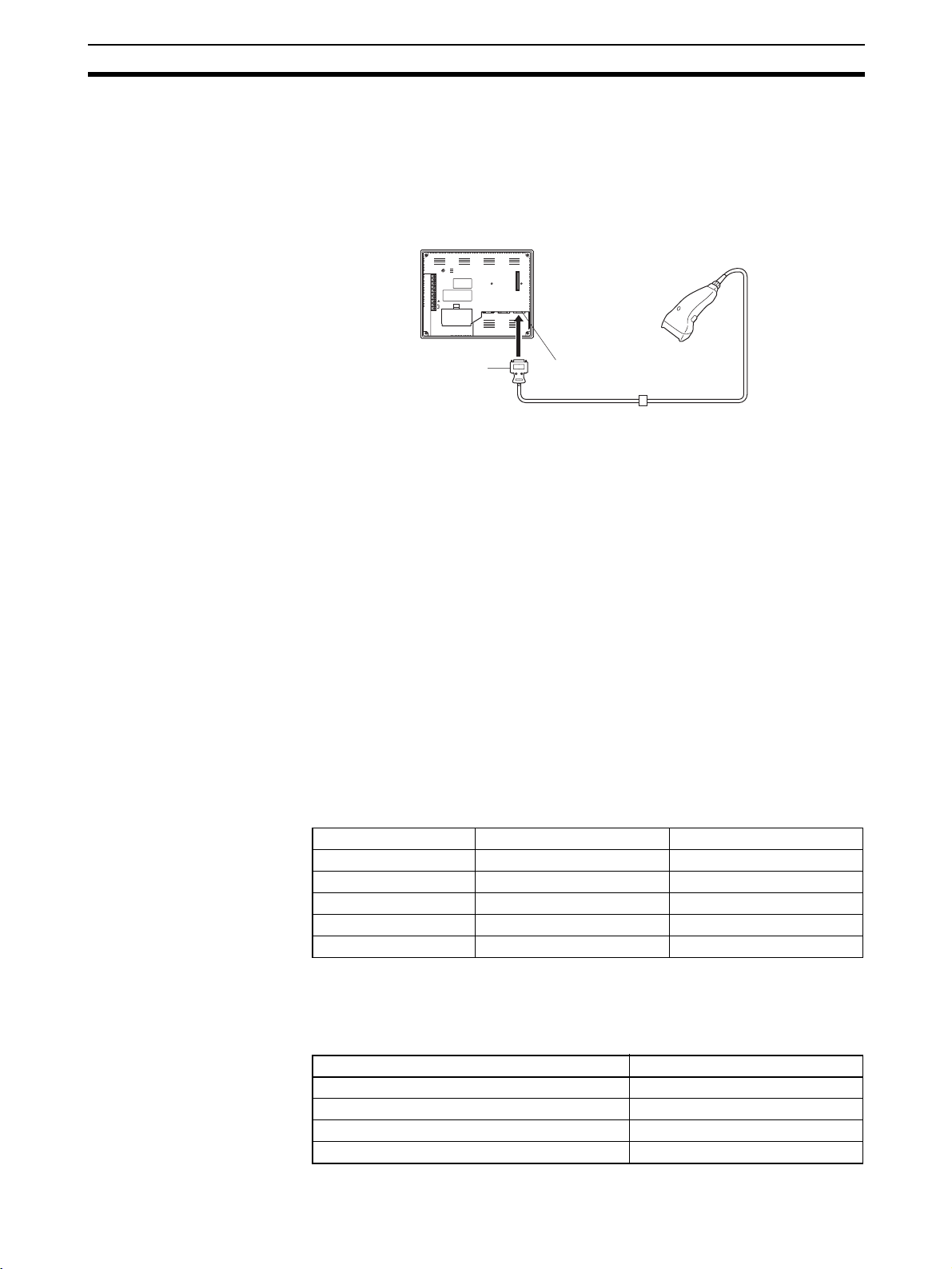
Connecting a Bar Code Reader Section 3-4
Note Make sure that the power supply to the bar code reader and the power supply
to the PT are both OFF before connecting or disconnecting the cable.
3-4-1 Connection Method
Connect the bar code reader to serial port A of the NT631/NT631C, as shown
in the figure below.
NT631/NT631C
9-pin connector
Bar code reader must match the communications setting (3-4-2 Setting a Bar
Code Reader, page 37) and data format (3-4-3 Data Format, page 38) in
order to connect to the NT631/NT631C. Please confirm the specification of
the bar code reader before using.
For details on making a connector cable, refer to Appendix G Making the
Cable for Connection to a Bar Code Reader.
Reference: The bar code reader must be connected to serial port A. This means that it
cannot be connected at the same time as the Support Tool. Note also that
when a bar code reader is used, the host must be connected at serial port B.
3-4-2 Setting a Bar Code Reader
After connecting a bar code reader, set the communications conditions and
other settings for it by selection from the system menu.
Bar code reader
RESET
RDA
TRM
RDB
SDA
SDB
CSA
CSB
24V
PRINTER PORT B PORT A
+DC
Serial port A
(RS-232C, 9-pin)
Connector cable Bar code reader cable
Settings at the NT631/
NT631C
Settings at the Bar Code
Reader
At the NT631/NT631C, set the communications conditions for communications with the bar code reader by using the memory switches, selecting from
the options indicated in the table below.
For more detailed information on the actual system menu operations, refer to
6-10 Setting the Bar Code Reader Input Function.
Item Possible Settings Default Setting
Data bits 7 or 8 bits 7 bits
Stop bit(s) 1 or 2 bits 2 bits
Parity None, odd, even Even
Communications speed 4800, 9600, 19200 bps 9600 bps
Input Method Manual, Auto Manual
Make the settings shown in the table below at the bar code reader. Make sure
that the communications speed, parity, stop bit, and data bit settings match
the communications settings made at the NT631/NT631C. For details on the
setting method, refer to the instruction manual for the bar code reader used.
Item Possible Settings
Communications speed 4800, 9600, 19200 bps
Parity EVEN, ODD, NONE
Stop bits 1 or 2 bits
Data bits 7 or 8 bits
37
Page 55

Connecting a Bar Code Reader Section 3-4
Item Possible Settings
Preamble STX
Postamble ETX
RS/CS control Available
Communications protocol No-protocol mode
Transmission of number of bar code label digits Transmission prohibited
Transmission of ID characters Transmission prohibited
Bar code types Multi-reading (all types can be
Trigger switch setting Automatic reading mode
About RS/CS Control
During bar code reading, the NT631/NT631C performs RS/CS control. When
the Input Method setting of the NT631/NT631C is set to Auto, the RS signal is
turned OFF, prohibiting the next input, until the read data has been sent to the
host as notification.
Because of this, when the Auto setting is made, the next input is not possible
until the data has been sent to the host as notification.
However, when the setting is Auto and the RS/CS signals of the cable are
shorted, RS/CS control is ineffective. Consequently, data input from the bar
code reader to the NT631/NT631C is updated regardless of whether or not
the data is sent to the host as notification.
For details, refer to the instruction manual for the bar code reader used.
read)
3-4-3 Data Format
The data format for communications when using the bar code input function of
the NT631/NT631C is shown below.
Data Data DataSTX ETX
(03
H)(02H)
The characters which are effective as data are hexadecimal codes from 20 to
7FH, and the maximum data length is 40 bytes.
Data which does not follow the data format described above is invalidated and
discarded.
38
Page 56

Using a Memory Unit Section 3-5
3-5 Using a Memory Unit
This section discusses the use of the Memory Unit.
Reference: The Memory Unit functions are determined by the model of PT being used,
regardless of the version of the system program installed in the PT.
PT Model Function of Memory Unit
Without V@ suffix System programs can not be transmitted using Memory Unit.
With V@ suffix System programs can be transmitted using Memory Unit.
By installing a Memory Unit (NT-MF261) on the NT631/NT631C, the screen
data in the NT631/NT631C can be recorded (backed up) in the Memory Unit.
In addition, the screen data in the Memory Unit can be automatically read into
the NT631/NT631C when it starts up. This means that system program and
screen data can be changed easily at the operation site without connecting to
the Support Tool.
The data in the Memory Unit is retained without backup by a battery or other
means.
In systems where there are frequent setup changes, by preparing a number of
Memory Units in advance and recording screen data in them in accordance
with the control performed in each case, the NT631/NT631C screen data can
be changed simply by installing the Memory Unit, without connecting to the
Support Tool.
In addition, even if NT631/NT631C is replaced, the previous status can be
maintained simply by installing the Memory Unit that retains the system program and screen data of the previous NT631/NT631C.
By using the following combinations, data can be stored (backed up) to a
Memory Unit.
• Screen data for two PTs.
• System program for two PTs.
• System program and screen data for one PT.
One Memory Unit can store the screen data for two PTs.
Note 1. Make sure that the power supply to the PT is OFF before connecting or dis-
connecting a Memory Unit.
After mounting a Memory Unit, be sure to tighten its two screws.
2. During data transmission, do not turn off the power supply to the NT631/
NT631C or reset it.
3. Do not touch the PCB (printed circuit board) with bare hands.
Reference: • When a Memory Unit is mounted, the NT631/NT631C cannot be set to
the operating status. On completion of data transmission with a Memory
Unit, always disconnect the Memory Unit from the NT631/NT631C before
starting NT631/NT631C operation.
• Memory Units (NT-MF261) can be used in common for the following PT
models: NT31, NT31C, NT631, and NT631C. One Memory Unit can store
screen data for up to two PTs of different models. However, since the data
compatibility is not complete between NT31/NT31C and NT631/NT631C,
an error may occur if an attempt is made to read NT631C data with an
NT31C. (The data must be converted using the Support Tool.)
Note also that although there is data compatibility between the NT31
and NT31C, and between the NT631 and NT631C, the display may not
be correct since these models have different numbers of colors.
39
Page 57

Using a Memory Unit Section 3-5
s
• One Memory Unit can store a system program for up to two PTs of different models. In order to transmit a system program from the Memory Unit
to the NT631/NT631C, the system program must be compatible to the target PT model.
• The statuses of memory switch settings and system settings can be
recorded to the Memory Unit besides screen data. When the data in the
Memory Unit is written into the NT631/NT631C, make sure that these settings can be adapted to the NT631/NT631C used before transmission.
3-5-1 Installation Method
Install the Memory Unit (NT-MF261) at the expansion interface connector at
the rear of the NT631/NT631C as shown in the figure below (the expansion
interface connector is located underneath the note label.).
Mounting screw
3-5-2 Method of Use
As shown in the figure below, a Memory Unit has two sets of four DIP
switches, and the operation is determined by the DIP switches that are set at
startup.
4321
OFF
SW1 SW2
OFF
Note 1. Always confirm that the power to the NT631/NT631C is off before setting
the DIP switches.
2. Do not touch the PCB (printed circuit board) directly with bare hands.
DIP Switch Functions The functions of the DIP switches on the Memory Unit are indicated in the
table below.
SW1
Switch Function
SW1-1 Automatic transmission (writing from the Memory
SW1-2 Automatic transmission (writing from the PT to the
Unit to the PT)
Memory Unit)
4321
Factory setting is turned all to off.
OFF: Not executed
ON: Executed
OFF: Not executed
ON: Executed
40
Page 58

Using a Memory Unit Section 3-5
Switch Function
SW1-3 Manual transmission (Direction of transmission and
bank used selected at the PT touch panel)
SW1-4 Data type to transfer OFF: Screen data
SW2
Switch Function
SW2-1 Disable/enable writing to PT OFF: Disable
SW2-2 Disable/enable writing to the Memory Unit OFF: Disable
SW2-3 Area (bank) selection of automatic transmission. * OFF: Bank 0
SW2-4 System/Screen simultaneous transmission OFF: Disable
*: The Memory Unit stores system program or screen data for one PT in each
of areas (bank 0, bank 1). (The total data storage is for two PTs.) SW2-3
sets which of these two banks is used for automatic transmission.
OFF: Not executed
ON: Executed
ON: System program
ON: Enable
ON: Enable
ON: Bank 1
ON: Enable
Reference: • In the following cases, a mode setting error occurs.
Writing Screen Data to a
Memory Unit Using
Automatic Transmission
(PT to Memory Unit)
Reference: When screen data is written to the Memory Unit, the data that has been
• More than one of the SW1-1 to SW1-3 switches are set to ON.
• None of the SW1-1 to SW1-3 switches are set to ON.
• In the following case, a protect setting error occurs.
Transmitting to the write destination has been disabled by the setting for
SW2-1 or SW2-2.
• In the following cases, a data transmission error occurs.
• An attempt is made to transmit data other than the system program to
PT system program area.
• An attempt is made to transmit the system program to PT screen data
area.
• For details on mode setting errors and protect setting errors, refer to
Errors When Using a Memory Unit (page 45).
In this mode, system program or the screen data in the NT631/NT631C is
forcibly written to the Memory Unit irrespective of the setting status of the
NT631/NT631C.
This mode is convenient if the touch panel is broken and touch switch operation is not possible, or if someone unfamiliar with touch switch operation at the
operation site is using the system.
stored in the specified area up until that point is lost (if the data is written into
only one Bank, the other Bank will not be affected).
Method of Execution
Use the following procedure to write the screen data in the NT631/NT631C to
the Memory Unit by automatic transmission.
41
Page 59

Using a Memory Unit Section 3-5
y
1,2,3... 1. Check that the power supply to the NT631/NT631C is OFF, then set the
DIP switches of the Memory Unit as follows after installing Memory Unit to
NT631/NT631C.
SW1
SW1-4 ON: System program
OFF: Screen data
SW2
SW2-3 ON: Bank 1
SW2-4 ON: System/Screen transmitted simultaneously
OFF: System/Screen not transmitted simultaneousl
OFF: Bank 0
It is not strictly necessary to set SW2-1 to OFF (to disable writing to the
PT), but it is recommended to do so to avoid loss of data in the event of
operating errors.
Reference: • Setting SW2-4 to ON (System/Screen transmitted simultaneously) dis-
ables the setting of SW1-4.
• Setting SW2-4 to ON (System/Screen transmitted simultaneously) disables the setting of SW2-3, writes the system program into bank 0, and
the screen data into bank 1 at all times.
2. Switch the NT631/NT631C power ON.
The screen data is automatically written into the Memory Unit. The screen
data in the NT631/NT631C is preserved.
The messages Preparing, Transmitting, Verifying, and Finished are displayed on the screen in accordance with the progress of data writing.
At the same time, the progress of the data writing status is displayed by the
means of the number of bytes and blocks (1 bank = 16 block = 1024k byte).
RUN LED operates as follows according to the processing status.
Preparing: flashes at intervals of 1 second
Transmitting: flashes at intervals of 0.5 second
Verifying: flashes at intervals of 0.5 second
Finished: lights up
3. Switch the NT631/NT631C power OFF, remove the Memory Unit.
To operate NT631/NT631C continuously, switch the NT631/NT631C power back ON.
Writing Screen Data to the
PT Using Automatic
Transmission (Memory
Unit to PT)
42
In this mode, the system program or screen data in the Memory Unit is forcibly
written to NT631/NT631C irrespective of the setting status of the NT631/
NT631C.
Since data transmission by this method is faster than when the Support Tool
or system installer is used, it can save a lot of time. When transmitting the
same system program or screen data to multiple NT631/NT631C, this mode
becomes convenient.
Page 60
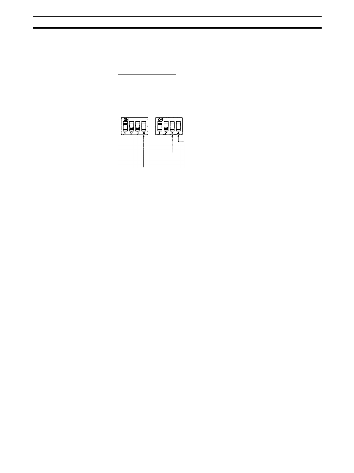
Using a Memory Unit Section 3-5
y
Reference: When data is written to the NT631/NT631C, the data that has been stored up
until that point is lost. When the system program is changed, the operation of
NT631/NT631C also changes.
Method of Execution
Use the following procedure to write the screen data in the Memory Unit to the
NT631/NT631C by automatic transmission.
1,2,3... 1. Check that the NT631/NT631C power is OFF, then set the DIP switches on
the Memory Unit as follows after installing Memory Unit to NT631/NT631C.
SW1
SW1-4 ON: System program
OFF: Screen data
SW2
SW2-4 ON: System/Screen transmitted simultaneously
SW2-3 ON: Bank 1
OFF: Bank 0
OFF: System/Screen not transmitted simultaneousl
It is not strictly necessary to set SW2-2 to OFF (to disable writing to the
Memory Unit), but it is recommended to do so to avoid loss of data in the
event of operating errors.
Reference: • Setting SW2-4 to ON (System/Screen transmitted simultaneously) dis-
ables the setting of SW1-4.
• Setting SW2-4 to ON (System/Screen transmitted simultaneously) disables the setting of SW2-3. In this case, the data transmission becomes
possible only if the data inside Memory Unit is in either of following combinations.
Bank 0: system program, Bank 1: other than system program
Bank 0: other than system program, Bank 1: system program
If the combination is not as listed above, a data transmitting error occurs.
• When writing the system program into the NT631/NT631C, the type of
system program inside Memory Unit and the type of PT must correspond.
2. Switch the NT631/NT631C power ON.
The screen data is automatically written into the PT.
The messages Preparing, Transmitting, Verifying and Finished are displayed on the screen in accordance with the progress of data writing.
At the same time, the progress of data writing status is displayed by the
means of the number of bytes and blocks (1 bank = 16 block = 1024k byte).
The RUN LED operates as follows according to the processing status.
Preparing: flashes at intervals of 1 second
Transmitting: flashes at intervals of 0.5 second
Verifying: flashes at intervals of 0.5 second
Finished: lights up
3. Switch the NT631/NT631C power OFF, remove the Memory Unit.
To operate NT631/NT631C continuously, switch the NT631/NT631C power back ON.
Reading and Writing Data
by Manual Transmission
In this method, the direction of transmission and area of the Memory Unit
used are set by touch switch operations at the NT631/NT631C. Transmission
can be executed while checking the settings.
43
Page 61
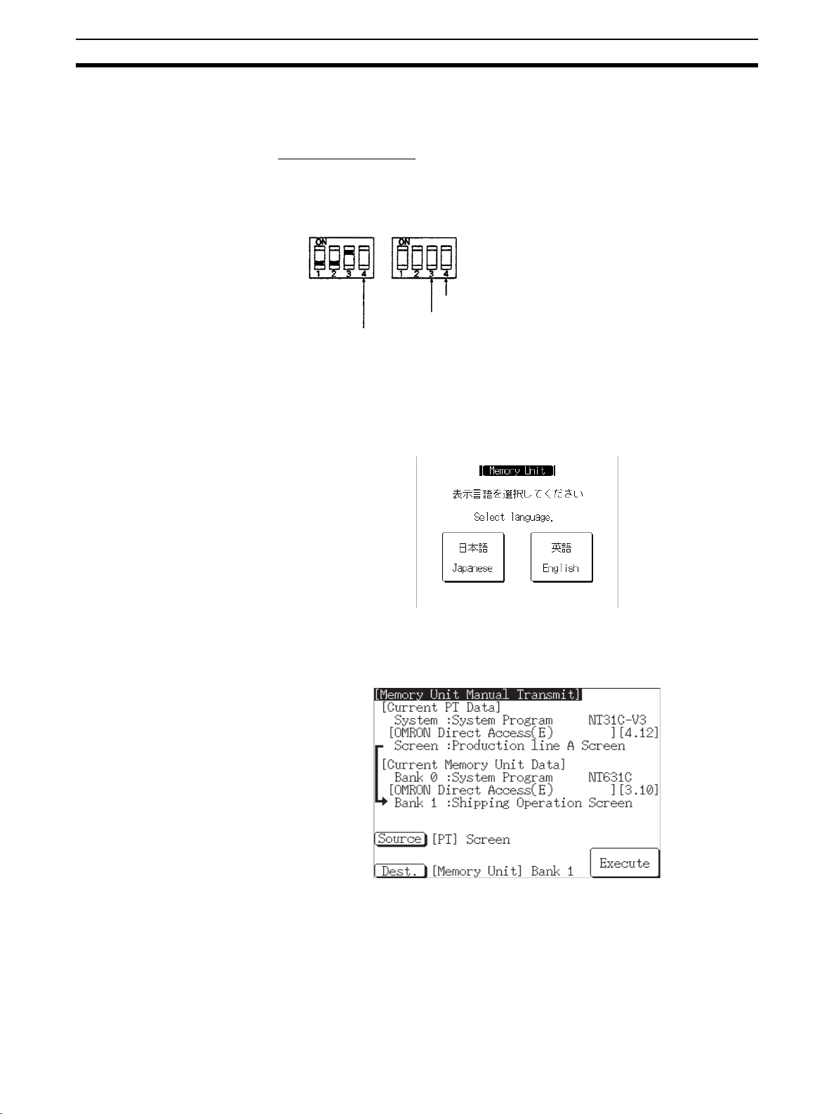
Using a Memory Unit Section 3-5
g
t
Reference: When data is written to the NT631/NT631C or Memory Unit, the data that has
been stored up until that point is lost.
Method of Execution
Use the following procedure to write screen data using manual transmission.
1,2,3... 1. Check that the NT631/NT631C power is OFF, then set the DIP switches on
the Memory Unit as follows.
SW1
Settin
SW2
Setting of SW2-4 not relevan
Setting of SW2-3 not relevant
of SW1-4 not relevant
In order to avoid loss of data in the event of operating errors, it is advisable
to set SW2-1 and SW2-2 so as to disable writing to the PT from which the
data is to be read.
2. Switch the NT631/NT631C power ON.
Display language select screen appears.
3. Press the Japanese or English touch switches to select the display language.
The following descriptions are for when English is selected.
The screen shown below is displayed.
44
Current PT Screen Data, System
The first line: Compatible PT type for the system program inside PT.
The second line: System program name and Version for the system pro-
gram inside PT.
(The second line may not be displayed in the kind of system program.)
Current PT Screen Data, Screen
The comment for the screen data in the NT631/NT631C is displayed here.
Page 62

Using a Memory Unit Section 3-5
Current Memory Unit Screen Data
• In the case of system program:
The first line: Compatible PT type for the system program in-
side the Memory Unit.
The second line: System program name and Version for the sys-
tem program inside the Memory Unit.
(The second line may not be displayed in the system program for some
models.)
• In the case of screen data:
The comment for the screen data in the NT631/NT631C is displayed
here.
The available transmitting destinations are altered depending on the settings
of the origin of transmitting as described in the table below.
Source Destination
PT screen
PT system
PT system/screen Memory Unit Bank 0/1 (fixed)
Memory Unit Bank 0 If system program is selected
Memory Unit Bank 1
Memory Unit Bank 0/1 PT system/screen (fixed)
Memory unit Bank 0
PT system (fixed)
If screen data is selected
PT screen (fixed)
Memory unit Bank 1
Reference: • When transmitting the system program and screen data simultaneously
Errors When Using a
Memory Unit
from the PT to the Memory Unit, the setting of banks is Bank 0: system
program, Bank 1: screen data, and when transmitting them from the
Memory Unit to the PT, either of the following combinations must be used.
Bank 0: system program, Bank 1: other than system program
Bank 0: other than system program, Bank 1: system program
• When writing the system program into the NT631/NT631C, the type of
system program inside Memory Unit and the type of PT must correspond.
4. Press Execute.
The data is transmitted.
The messages Preparing, Transmitting, Verifying, and Finished are displayed in accordance with the progress of data transmission. At the same
time, the progress of data transmitting status is displayed by the means of
the number of bytes and blocks (1 bank = 16 block = 1024k byte).
When the data transmission is operated manually, RUN LED remains OFF.
5. Switch the NT631/NT631C power OFF, remove the Memory Unit, then
switch the NT631/NT631C power back ON.
If an error occurs when using the Memory Unit, the NT631/NT631C operates
as follows.
• The details of the error and remedial action are displayed on the screen.
Each screen has touch switches to change the display language from
one to the other. When the manual data transmission is operating, the
content of error and remedial action are shown with selected language. When the automatic transmission is operating, it is displayed in
Japanese.
• The continuous buzzer sounds.
45
Page 63

Using a Memory Unit Section 3-5
• The RUN LED flashes.
If a protect setting error occurs when executing manual transmission, it is possible to return to the Memory Unit manual transmission screen by pressing
the OK touch switch, but in the case of other errors, the status described
above remains in effect until the NT631/NT631C power is turned OFF or
reset.
Within the PT Model, the
system program inside
memory compatible PT
model
The compatibility relationships are shown below.
NT631
NT631C
NT631C-EV3 System program for NT631C with the -V3 suffix
System program for NT631/NT631C without the -V suffix, and for
NT631/NT631C with the -V1 and -V2 suffix
When an error occurs, take remedial action by referring to the table below.
Error Probable Cause Remedial Action
Mode setting error DIP switches SW1-1 to
SW1-3 are all OFF, or
more than one is ON.
Protect setting error
(automatic transmission)
Protect setting error
(manual transmission)
Flash memory error An error occurred during
Verify error An error occurred during
Transmitting data
error
(The automatic
transmission only)
Writing to the data write
destination has been prohibited by the setting of
SW2-1 or SW2-2.
Writing to the data write
destination has been prohibited by the setting of
SW2-1 or SW2-2.
initialization of the
NT631/NT631C or Memory Unit flash memory, or
during write processing.
verification processing at
the flash memory of the
NT631/NT631C or the
Memory Unit.
An attempt is made to
transmit data other than a
system program or the
system program of a different PLC model into the
NT631/NT631C as the
system program.
An attempt is made to
write a system program
into the NT631/NT631C
as screen data.
Turn the NT631/NT631C power
OFF, set the Memory Unit DIP
switches correctly, then turn the
NT631/NT631C power back ON.
Turn the NT631/NT631C power
OFF, set the Memory Unit DIP
switches correctly, then turn the
NT631/NT631C power back ON.
Perform either of the following procedures.
• Press the OK touch switch to
return to the Memory Unit manual
transmission screen, make the
correct settings, then try again.
• Turn the NT631/NT631C power
OFF, correct the DIP switches settings of the Memory Unit, then
turn the power back ON.
Turn the NT631/NT631C power
OFF, then back ON. If the error
recurs, the flash memory at the
write destination may be faulty. In
this case, replace the PT.
Turn the NT631/NT631C power
OFF, then back ON. If the error
recurs, the flash memory at the
write destination may be faulty. In
this case, replace the PT.
Perform either of the following procedures.
• Turn the NT631/NT631C power
OFF, correct the DIP switch settings of the Memory Unit, and
then turn the power back ON.
• Turn the NT631/NT631C power
OFF, set the DIP switch settings
to the manual transmission, and
then check the data inside the
Memory Unit.
46
Page 64

Connecting to the Host from the RS-232C Port
This section describes the method for connecting to the host using the RS-232C port of the PT.
4-1 Connecting to the RS-232C Port at the Host . . . . . . . . . . . . . . . . . . . . . . . . . 48
4-1-1 Host Types and Settings. . . . . . . . . . . . . . . . . . . . . . . . . . . . . . . . . . 48
4-1-2 Connecting Directly between RS-232C Ports . . . . . . . . . . . . . . . . . 73
SECTION 4
47
Page 65

Connecting to the RS-232C Port at the Host Section 4-1
4-1 Connecting to the RS-232C Port at the Host
The method for connecting between the RS-232C port of the PT and the RS232C port of the host is as follows.
The following discussion is focused on the connection method to OMRON
PLCs (By using the memory link method, a connection can be made to any
arbitrary RS-232 unit). When making a connection to a host other than
OMRON PLCs, refer to the PLC Connection Manual (V042-E1-@) or NT31/
631 Multi Vendor Connection Manual (V060-E1-@).
Direct Connection Between The RS-232C Ports Using an RS-232C Cable
(page 73)
This is the easiest connection method. Depending on the host to which the
connection is to be made, it may be possible to use OMRON cables with connectors.
NT631/NT631C
Reference: The CS/CJ-series CPU Unit cannot be connected with the 1:1 connection NT
Link method. Use the 1:N connection NT Link method instead to make the 1:1
connection. For details, refer to Using the NT Link (1:N) Method (page 65) or
Using the High-speed NT Link (1:N) Method (page 70).
4-1-1 Host Types and Settings
The types of host that can be connected to a PT by using the RS-232C ports
of both Units, and the settings to be made at the host, are described here.
When Using the Host Link
Method
Compatible Host Units
Some models and series of OMRON PLCs have the host link function built in.
In the CS/CJ-series or CQM1H PLCs, the host link method can be used by
installing a Serial Communications Board/Unit. In addition, some C200HX/
HG/HE(-Z)E CPU Unit can be connected in the host link method by installing
a Communications Board.
Check the model and series of the PLC, the type of installed Serial Communications Board, Serial Communications Unit, or Host Link Unit before making a
connection.
The hosts that can be connected to the NT631/NT631C by the host link
method using the RS-232C ports of both Units are indicated in the table
below.
Host
RS-232C cable (max. 15 m)
PLC
Series
CS Series CS1G-CPU42/43/44/45-E(V1)
CJ Series CJ1G-CPU44/45
Units with Built-in Host Link
Function
CS1H-CPU63/64/65/66/67-E(V1)
CS1G-CPU42H/43H/44H/45H
CS1H-CPU63H/64H/65H/66H/67H
CS1D-CPU65H/67H
CJ1G-CPU42H/43H/44H/45H
CJ1H-CPU65H/66H/67H
CJ1M-CPU11/12/13/22/23
48
CPU Units Connectable with
Host Link Units or Expansion
Communications Board/Units
CS1G-CPU42/43/44/45-E(V1)
CS1H-CPU63/64/65/66/67-E(V1)
CS1G-CPU42H/43H/44H/45H
CS1H-CPU63H/64H/65H/66H/67H
CS1D-CPU65H/67H
CJ1G-CPU44/45
CJ1G-CPU42H/43H/44H/45H
CJ1H-CPU65H/66H/67H
CJ1M-CPU11/12/13/22/23
(*1)
Host Link Unit or
Communications
Board/Unit
CS1W-SCU21(-V1)
CS1W-SCB21(-V1)
CS1W-SCB41(-V1)
CJ1W-SCU21(-V1)
CJ1W-SCU41(-V1)
Connect-
able to
CS1G
CS1H
CS1D
CJ1G
CJ1H
CJ1M
Page 66

Connecting to the RS-232C Port at the Host Section 4-1
PLC
Series
Units with Built-in Host Link
Function
CPU Units Connectable with
Host Link Units or Expansion
Communications Board/Units
C Series C1000H-CPU01-EV1
C2000H-CPU01-EV1
C200HS-CPU01/03/21/23/
31/33-E
C200HE-CPU11/32/42-E
C200HE-CPU11/32/42-ZE
C200HG-CPU33/43/53/63-E
C200HG-CPU33/43/53/63-ZE
C200HX-CPU34/44/54/64-E
C200HX-CPU34/44/54/64
65/85-ZE
C200HS-CPU21/23/31/33-E C200HW-COM02/04/
C200HE-CPU42-E
C20HE-CPU42-ZE
C200HG-CPU43/63-E
C200HG-CPU43/63-ZE
C200HX-CPU44/64-E
C200HX-CPU44/64/65/85-ZE
C200HE-CPU32/42-E
C200HE-CPU32/42-ZE
C200HG-CPU33/43/53/63-E
C200HG-CPU33/43/53/63-ZE
C200HX-CPU34/44/54/64-E
C200HX-CPU34/44/54/64/
65/85-ZE
C1000H-CPU01-EV1
C2000H-CPU01-EV1
C1000H-CPU01-EV1
C1000HF-CPU01-EV1
C2000H-CPU01-EV1
CPM1-10/20/30CDR-@
+CPM1-CIF01
CPM1A-10/20/30/40CD@-@
+CPM1-CIF01
CPM2A-30/40/60CD@@-@
+CPM1-CIF01
(Peripheral port connection)
CPM2C-10/20@@@@@@-@
(*2)
CQM1-CPU21-E
CQM1-CPU41/42/43/44-EV1
CV Series
(*4)
CQM1H-CPU11/21/51/61
(*3)
CV500-CPU01-EV1 CV500-CPU01-EV1 CV500-LK201 CV500
CV1000-CPU01-EV1 CV1000-CPU01-EV1 CV1000
CQM1H-CPU51/61 CQM1H-SCB41 CQM1H
CV2000-CPU01-EV1 CV2000-CPU01-EV1 CV2000
CVM1
Series
(*4)
Compo-
CVM1-CPU01-EV2
CVM1-CPU11-EV2
CVM1-CPU21-EV2
CVM1-CPU01-EV2
CVM1-CPU11-EV2
CVM1-CPU21-EV2
SRM1-C02-V1 SRM1
Bus/S
Master
Control
Unit
Host Link Unit or
Communications
Connect-
able to
Board/Unit
C120-LK201-EV1 C1000H
C2000H
C200H-LK201-EV1 C200HS
C200HE
C200HE-Z
C200HG
C200HG-Z
C200HX
C200HX-Z
C200HS
05/06-EV1
C200HE
C200HE-Z
C200HG
C200HG-Z
C200HX
C200HX-Z
C500-LK201-EV1 C1000H
C2000H
C500-LK203 C1000H (F)
C2000H
CPM1
CPM2A
CPM2C
CQM1
CV500-LK201 CVM1
*1
This CPU Unit is for a Duplex-CPU Unit System. The CS1W-SCB21/42(-V1) Serial Communications Board
cannot be used.
49
Page 67

Connecting to the RS-232C Port at the Host Section 4-1
*2
Use a CPM2C-CN111 or CS1W-CN114/118 Connecting Cable, CPM1-CIF01 RS-232C Adapter, or CPM1CIF11 RS-422A Adapter to connect.
*3
The CQM1H-CPU11 does not have a built-in RS-232C port, so connect to the peripheral port to the PT with
a CS1W-CN118 Connecting Cable.
*4
CPU Units of CVM1/CV-series PLCs without the suffix -EV@ cannot be connected.
Settings at The Host
When using the host link method, the settings shown below must be made at
the host (depending on the Unit, some of these settings may not be necessary, or settings not shown here may be necessary).
Item Switch Setting
I/O port RS-232C
Communications speed
Set the same speed as for the NT631/NT631C.
Transfer code ASCII, 7 data bits, 2 stop bits
Parity Even
1-to-1/1-to-N
1-to-N
(*2)
Instruction level Level 1, 2, 3
Unit # 00
Set the host link communications speed at 9600 bps or 19200 bps with the
memory switch at the NT631/NT631C. For details, refer to 6-7-2 Setting the
Host Link Method (page 155).
The 1-to-N setting enables BCC (Block Check Character). It is not actually possible to connect more than one NT631/NT631C in a single host link.
The setting methods for each type of Unit are described in the following.
(*1)
Connecting to a C-series
Host Link Unit
C200H/C200HS/C200HE/HG/HX (-Z)E Rack-mounting Unit: C200H-LK201V1
Setting the Front Switches
Set each switch with a flat blade screwdriver so that the values or symbols in
the setting value window agree with the following.
LK201
RUN
RCV
SW1
SW3
XMT
ERROR
SW2
0
0
SW4
2
5
• Unit # (SW1, SW2)
Set these switches to 0.
• Instruction level, parity, and transfer code (SW4)
Set this switch to 2.
• Communications speed (SW3)
Set this switch to 5 to select 9600 bps.
Set this switch to 6 to select 19200 bps.
50
Page 68

Connecting to the RS-232C Port at the Host Section 4-1
Setting the Rear Switches
CTS selector switch
External
0 V (ON)
ON
1
2
3
4
• 1-to-1/1-to-N selection (DIP switch)
Set #3 to ON.
• CTS selection (selector switch)
Set this always to 0 V (ON).
C1000H(F)/C2000H Rack-mounting Unit: 3G2A5-LK201-EV1
Setting the Front Switches
Local
Host
• Mode control (key switch)
Set this to host link.
Setting the Rear Switches
I/O port
RS-422A
RS-232C
Synchronization
Internal
External
Terminator
OFF
ON
CTS
0 V
External
ON
ON
• I/O port selection (selector switch)
Set this to RS-232C.
8
7
6
5
SW1
4
3
2
1
• Unit # (DIP SW1)
Set SW1-1 to SW1-5 to OFF (0).
• Synchronization (selector switch)
8
7
6
SW2
5
4
3
2
1
Set this to Internal.
• Communications speed
(DIP SW2-1 to SW2-4)
Set these switches to 0010 to select
19,200 bps.
Set these switches to 1010 to select
9,600 bps.(0: OFF 1: ON)
• 1-to-1/1-to-N selection (DIP SW2-6)
Set SW2-6 to OFF (0) (1-to-N).
• Instruction level (DIP SW2-7, SW2-8)
Set these switches to ON (1).
(Levels 1, 2, and 3 are enabled.)
• CTS selection (selector switch)
Set this always to 0 V (ON).
51
Page 69
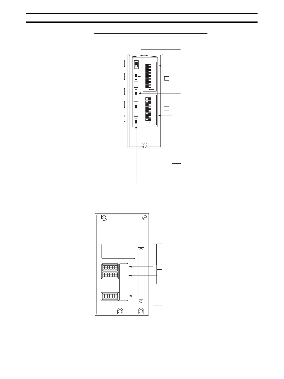
Connecting to the RS-232C Port at the Host Section 4-1
y
C1000H/C2000H Rack-mounting Unit: C500-LK203
Setting the Rear Switches
• I/O port selection (selector switch)
Set this to RS-232C.
5 V supply
ON
OFF
I/O port
RS-422A
RS-232C
Synchronization
Internal
External
Terminator
OFF
ON
CTS
0 V
External
8
7
6
5
SW1
4
3
2
1
ON
8
7
6
SW2
5
4
3
2
1
ON
• Unit #, parity, and transfer code
(DIP SW1-1 to SW1-7)
Set SW1-1 to SW1-7 to OFF (0).
• Synchronization (selector switch)
Set this to Internal.
• Communications speed
(DIP SW2-1 to SW2-4)
Set these switches to 0010 to select
19,200 bps.
Set these switches to 1010 to select
9,600 bps.(0: OFF 1: ON)
• 1-to-1/1-to-N selection (DIP SW2-6)
Set SW2-6 to OFF (0) (1-to-N).
• Instruction level (DIP SW2-7, SW2-8)
Set these switches to ON (1).
(Levels 1, 2, and 3 are enabled.)
• CTS selection (selector switch)
Set this alwa
s to 0 V (ON).
C200H/C1000H/C2000H CPU-mounting Unit: 3G2A6-LK201-EV1
Setting the Rear Switches
• Unit #, parity, and transfer code
(DIP SW1-1 to SW1-5)
Set SW1-1 to SW1-5 to OFF (0).
* Parity is fixed at Even Parity. Transfer code is
fixed at ASCII 7 data bits and 2 stop bits.
• Communications speed (DIP SW2-1 to SW2-4)
Set these switches to 0010 to select 19200 bps.
Set these switches to 1010 to select 9600 bps.
(0: OFF 1: ON)
SW1
SW2
SW3
• 1-to-1/1-to-N selection (DIP SW2-6)
Set SW2-6 to OFF (0) (1-to-N).
• Instruction level (DIP SW2-7, SW2-8)
Set these switches to ON (1).
(Levels 1, 2, and 3 are enabled.)
52
• CTS selection (DIP SW3-1 and SW3-2)
Set SW3-1 to ON (1), and SW3-2 to OFF (0).
(Set this always to 0V.)
• Synchronization (DIP SW3-3 to SW3-6)
Set SW3-3, SW3-5, and SW3-6 to ON (1), and
SW3-4 to OFF (0). (Set these to Internal.)
Page 70

Connecting to the RS-232C Port at the Host Section 4-1
Connecting to a CVM1/CVseries Host Link Unit
CVM1/CV-series Rack-mounting Unit: CV500-LK201
A CVM1/CV-series Host Link Unit (CV500-LK201) has two connectors (communications ports 1 and 2). Either of these ports can be used for connection
to an NT631/NT631C by the RS-232C method. However, since the connectors at these ports are of different types, a cable that matches the connector
must be prepared.
• Communications port 1
Communications port 1 is a 25-pin connector for RS-232C use only.
• Communications port 2
Communications port 2 is a 9-pin connector which allows selection of the
RS-232C or RS-422A method. When this port is used with the RS-232C
method, the I/O port selector switch on the front of the PT must be set to
RS-232C (the upper position).
CPU Bus Unit Settings
When connecting to a CVM1/CV-series Host Link Unit, set the following communications conditions for the CPU Bus Unit settings.
Item Setting at Host
Communications speed
Transfer code ASCII, 7 data bits, 2 stop bits
Parity Even
1-to-1, 1-to-N
Instruction level Level 1, 2, 3
Set the same speed as set at the NT631/NT631C
(*2)
1-to-N
(*1)
*1
Set the host link communications speed at 9600 bps or 19200 bps with the
memory switch at the NT631/NT631C. For details, refer to 6-7-2 Setting the
Host Link Method (page 155).
*2
The 1-to-N setting enables BCC (Block Check Character). It is not actually
possible to connect more than one NT631/NT631C in a single host link.
Set the CPU Bus Unit settings directly from a Programming Device (e.g. CXProgrammer).
For details on the CPU Bus Unit settings, refer to the SYSMAC CVM1/CV-
series Host Link Unit Operation Manual (W205-E1-@).
53
Page 71

Connecting to the RS-232C Port at the Host Section 4-1
Setting The Front Switches
• Unit # (SW3, SW4)
When using communications port 2, set
Communications port 1
(RS-232C)
Communications port 2
(RS-232C/RS-422A)
I/O port selector switch
RS-232C
RS-422A
these switches to 0.
• I/O port selection (selector switch)
Set this to RS-232C.
• CTS selection (DIP SW2 and SW3)
Set SW2 or SW3 to ON. (Set this always to 0 V.)
To use communications port 1, set SW2. To
use communications port 2, set SW3.
• Communications condition setting (DIP SW1)
Set this switch to OFF.
Communications are executed in
accordance with the CPU Bus Unit system
settings made at the PLC. The initial values
for the system settings are as follows.
- Communications speed: 9600 bps
- Parity: Even
- Xon/Xoff control: Not executed
- Communications method: Full duplex
- Stop bits: 2 stop bits
- Data length: 7 bits
Connecting to a CPU Unit CV-series and CVM1/CV-series (-EV
CV500-CPU01-EV1/CV1000-CPU01-EV1/CV2000-CPU01-EV1
CVM1-CPU01-EV2/CVM1-CPU11-EV2/CVM1-CPU21-EV2
PLC Setup
When connecting to a CVM1/CV-series CPU Unit, set the following communications conditions for the PLC Setup.
Item Setting at Host
Communications speed
Set the same speed as set at the NT631/NT631C
Stop bit 2 stop bits
Parity Even
Data length ASCII 7 bits
Unit # 00
*1
Set the host link communications speed at 9600 bps or 19200 bps with the
memory switch at the NT631/NT631C. For details, refer to 6-7-2 Setting the
Host Link Method (page 155).
Either set PLC Setup directly from a Programming Device (e.g. CX-Programmer), or transmit the PLC Setup made at a Programming Device to the CPU
Unit.
For details on the PLC Setup, refer to the SYSMAC CVM1/CV500/1000/2000
Operation Manual: Ladder Diagrams (W202-E1-@).
@) CPU Units
(*1)
54
Page 72
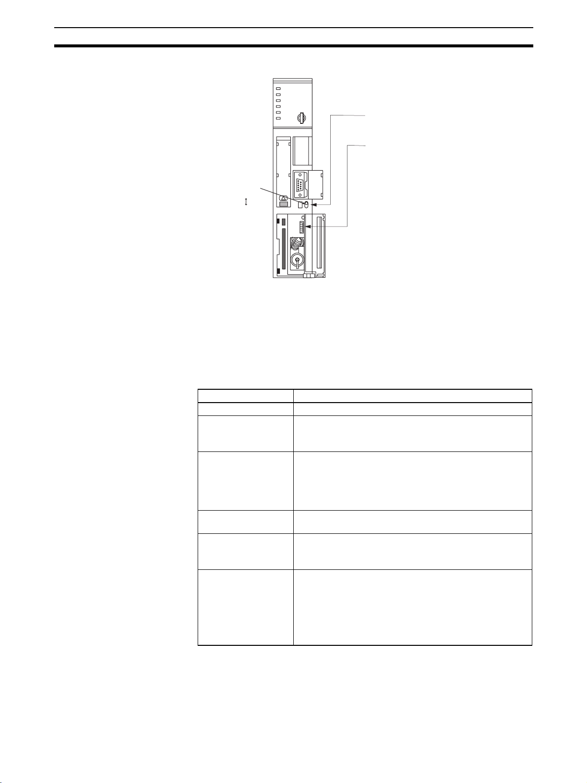
Connecting to the RS-232C Port at the Host Section 4-1
Setting the Front Switches
• I/O port selection (selector switch)
Set this to RS-232C.
• System setting (DIP SW4)
To effect the existing DIP switch
settings, set SW4 to ON.
To effect the existing PLC Setup,
I/O port selector switch
RS-232C
RS-422A
set SW4 to OFF.
Note
For CPU Units manufactured before or
during June 1995 (lot No. @@65), the
existing DIP switch settings differ from
the existing PLC Setup as follows.
- DIP switch settings:
2,400 bps, 1 stop bit, even parity, 7 bit
data length
- PLC Setup:
9,600 bps, 2 stop bits, even parity, 7 bit
data length
For CPU Units manufactured from July
1995 onward (lot No. @@75), the values
specified in the DIP switch settings also
are 9,600 bps and 2 stop bits.
C-series C200HS, C200HX/HG/HE(-Z)E, CPM1, CPM2A, CPM2C, CQM1,
CPM1H CPU Units, SRM1
The connection method depends upon the model of PLC being used, as
shown in the following table.
PLC model Connection method
C200HS, CQM1 Connect to the CPU Unit’s built-in RS-232C port.
C200HX/HG/HE(-Z)E Connect to the CPU Unit’s built-in RS-232C port.
Connect to one of the RS-232C ports (port A or port B) on a
Serial Communications Board.
CQM1H Connect to the CPU Unit’s built-in RS-232C port.
Connect to the peripheral port through a CS1W-CN118
Connecting Cable.
Connect to the RS-232C port (port 1) on a Serial Communications Board.
CPM1 Connect to the peripheral port through a CPM1-CIF01 RS-
CPM2A, SRM1 Connect to the CPU Unit’s built-in RS-232C port.
CPM2C Connect to the CPU Unit’s RS-232C port or the peripheral
232C Adapter.
Connect to the peripheral port through a CPM1-CIF01 RS232C Adapter.
port through a Connecting Cable (CPM2C-CN111, CS1WCN118, or CS1W-CN114).
(The CPM2C-CN111 splits the Unit’s Communications Port
into a RS-232C port and a peripheral port. A CPM1-CIF01
RS-232C Adapter is also required to connect to this peripheral port.)
55
Page 73

Connecting to the RS-232C Port at the Host Section 4-1
PLC Setup Area Settings
When connecting to a C200HS, C200HX/HG/HE(-Z)E, CPM1, CPM2A,
CPM2C, CQM1, or CQM1H CPU Unit, or SRM1, set the following communications conditions for the PLC Setup area.
Item Setting at Host
Communications mode Host link mode
Communications speed
Stop bit 2 stop bits
Parity Even
Data length ASCII 7 bits
Unit # 00
*1
Set the host link communications speed at 9600 bps or 19200 bps with the
Set the same speed as set at the NT631/NT631C
memory switch at the NT631/NT631C. For details, refer to 6-7-2 Setting the
Host Link Method (page 155).
Set the PLC Setup area settings directly from a Programming Device (e.g.
CX-Programmer).
For details on operations relating to the PLC Setup area, refer to the manual
for the PLC which is used.
The PLC Setup area word numbers and settings to be made depending on
the Unit and port to which the connection is made are shown below.
CPM2A, CPM2C, CQM1H, or SRM1: Peripheral port connection
Word # Writing Value Settings
DM6650 0001 Host link mode, no CTS control
Communications conditions set by the contents of DM
DM6651 0303 Data length 7 bits, 2 stop bits, even parity, communica-
tions speed: 9600 bps
0304 Data length 7 bits, 2 stop bits, even parity, communica-
tions speed: 19200 bps
DM6653 0000 Unit # 00
(*1)
56
C200HS, C200HX/HG/HE(-Z)E, CPM2A, CPM2C, CQM1, CQM1H (other
than the CPU11), or SRM1: Built-in RS-232C port connection
Word # Writing Value Settings
DM6645 0001 Host link mode, no CTS control
Communications conditions set by the contents of DM
DM6646 0303 Data length 7 bits, 2 stop bits, even parity, communica-
tions speed: 9600 bps
0304 Data length 7 bits, 2 stop bits, even parity, communica-
tions speed: 19200 bps
DM6648 0000 Unit # 00
C200HX/HG/HE(-Z)E: Serial Communications Board port A
CQM1H: Serial Communications Board port 1
Word # Writing Value Settings
DM6555 0001 Host link mode, no CTS control
Communications conditions set by the contents of DM
Page 74

Connecting to the RS-232C Port at the Host Section 4-1
Word # Writing Value Settings
DM6556 0303 Data length 7 bits, 2 stop bits, even parity, communica-
0304 Data length 7 bits, 2 stop bits, even parity, communica-
DM6558 0000 Unit # 00
When using port B of the Communications Board of C200HX/HG/HE(-Z)E
Word # Writing Value Settings
DM6550 0001 Host link mode, no CTS control
DM6551 0303 Data length 7 bits, 2 stop bits, even parity, communica-
0304 Data length 7 bits, 2 stop bits, even parity, communica-
DM6553 0000 Unit # 00
When using a CPM1
Word # Writing Value Settings
DM6650 0001 Host link mode
DM6651 0303 Data length 7 bits, 2 stop bits, even parity, communica-
0304 Data length 7 bits, 2 stop bits, even parity, communica-
DM6653 0000 Unit # 00
tions speed: 9600 bps
tions speed: 19200 bps
Communications conditions set by the contents of DM
tions speed: 9600 bps
tions speed: 19200 bps
Communications conditions set by the contents of DM
tions speed: 9600 bps
tions speed: 19200 bps
Connecting to a CPM2C
The CPM2C PLCs do not have the same kind of port connectors found on CS/
CJ-series PLCs. The CPM2C’s communications port handles both RS-232C
and peripheral port connections which are divided internally. Therefore, when
using the CPM2C, it is necessary to select RS-232C or peripheral port connections, according to the kind of cable and port (on the cable) used, as
shown in the following table. Refer to the CPM2C Operation Manual for more
details.
Port connecting to PT PLC Setup
RS-232C port (D-Sub 9-pin) of CPM2C-CN111 Built-in RS-232C port settings
Peripheral port of CPM2C-CN111 Peripheral port settings
RS-232C port (D-Sub 9-pin) of CS1W-CN118 Built-in RS-232C port settings
Peripheral port of CS1W-CN114 Peripheral port settings
Peripheral port
CPM2C-CN111
RS-232C port
(D-Sub 9-pin, female)
CPM2C
CS1W-CN118
RS-232C port
(D-Sub 9-pin, female)
CPM2C
CS1W-CN114
Peripheral port
CPM2C
Setting the DIP Switches of a C200HX/HG/HE(-Z)E, CQM1 or CQM1H
When using a C200HX/HG/HE(-Z)E, CQM1, or CQM1H the DIP switches on
the front panel must be set as shown below in order to make the settings in
the PLC Setup area (data memory) effective.
57
Page 75

Connecting to the RS-232C Port at the Host Section 4-1
C200HX/HG/HE(-Z)E
RS-232C port communications condition setting
Set DIP SW5 to OFF to make the settings made
in PC Setup effective.
CQM1 CQM1H
When using the CQM1H’s built-in peripheral port, turn ON SW7.
Setting the Switches of a CPM2A
When using a CPM2A, the switches on the front panel must be set as shown
below in order to make the PLC Setup settings effective.
Set the Communications
switch to OFF (down
position).
Setting the Switches of a CPM2C
When using a CPM2C, the switches on the front panel must be set as shown
below in order to make the PLC Setup settings effective.
The settings for SW1 and SW2 depend upon the usage of
the peripheral port and RS-232C port.
• Connecting PT to peripheral port
• Connecting PT to built-in RS-232C port
(A device that requires non-standard communications settings
is connected to the peripheral port.)
SW1: OFF
SW2: ON
• Connecting PT to built-in RS-232C port
(A Programming Console is connected to the peripheral port.)
SW1: OFF
SW2: OFF
Setting the Switches on a RS-232C Adapter
When using a CPM1-CIF01 RS-232C Adapter, set the mode switch as shown
in the following diagram.
CPM1CIF01
Set the mode setting switch to HOST (upper position).
CPM1
58
Page 76

Connecting to the RS-232C Port at the Host Section 4-1
CS/CJ-series CPU Unit: CS1G/H-CPU@@-E(V1), CS1G/H/D-CPU@@H
CJ1G/M-CPU@@, CJ1G/H-CPU@@H
Connect to the built-in RS-232C port of the CPU Unit, or the RS-232C port of
the Communications Board. Note that the connection to a peripheral port
must be made via an RS-232C adapter (CS1W-CN118) specially designed for
connecting to a peripheral port.
PLC Setup
When connecting to a CS/CJ-series CPU Unit, set the following communications conditions for the PLC Setup area. Since the settings shown below are
the PLC default settings for the CPU Unit, no change to the PLC Setup is nec-
essary as long as the communications speed is maintained at 9600 bps.
Item Setting at Host
Communications speed Set the same speed as set at the NT631/NT631C(*1)
Stop bits 2 stop bits
Parity Even
Data length ASCII 7 bits
Unit No. for the host link 00
*1
Set the host link communications speed at 9600 bps or 19200 bps with the
memory switch at the NT631/NT631C. For details, refer to 6-7-2 Setting the
Host Link Method (page 155).
When the communications speed is set to 19200 bps., the PLC Setup of
the CPU Unit need to be changed.
Either set the PLC Setup directly from a Programming Device (Programming
Console), or transmit the PLC Setup made at a Programming Device (CXProgrammer) to the CPU Unit.
For details on the PLC Setup, refer to the SYSMAC CS Series Operation
Manual (W339) or the SYSMAC CJ Series Operation Manual (W393).
Using the CPU Unit’s Built-in RS-232C Port
Word # Writing Value Settings
160 8000 Host link mode, data length 7 bits,
2 stop bits, even parity
161 0000 Communications speed: 9600 bps.
0007 Communications speed: 19200 bps.
166 0000 Unit #00
Using the CPU Unit’s Peripheral Port
Word # Writing Value Settings
144 8000 Host link mode, data length 7 bits,
145 0000 Communications speed: 9600 bps.
0007 Communications speed: 19200 bps.
150 0000 Unit #00
2 stop bits, even parity
Setting the Front Switches
Set the CPU Unit’s DIP switches to 4 or 5 in accordance with the port NT631/
NT631C is connected to. An example of a CS-series CPU Unit is shown
below.
59
Page 77
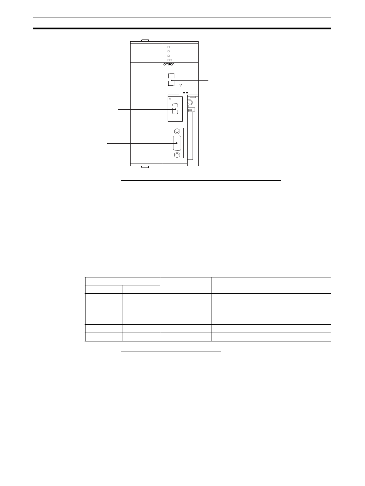
Connecting to the RS-232C Port at the Host Section 4-1
RUN
ERR/ALM
INH
PRPHL/COMM
SYSMAC CS1G
PROGRAMMABLE CONTROLLER
CPU42
Peripheral port
This is used mainly for
connection to the
Programming Device.
(This also supports the
RS-232C unit connection.)
RS-232 port
This is used mainly for
connection to the RS-232C
unit.
(This also supports the
CX-Programmer.)
OPEN
BUSY
MCPWR
OPEN
PERIPHERAL
PORT
Connecting to CS-series Serial Communications Board
Serial Communications Board equipped with a RS-232C port for CS-series
CPU Units: CS1W-SCB21(-V1)/41(-V1) (See note.)
Note Cannot be used with the CS1D-CPU65H/67H.
DIP switches (inside the battery storage)
• Set SW4 to ON (establishing communications in
accordance with PC Setup) when connecting the
NT631/NT631C to a peripheral port.
• Set SW5 to OFF (establishing communications
in accordance with PC Setup) when connecting
the NT631/NT631C to a peripheral port.
Allocation DM area (words) Writing Value Settings
Port 1 Port 2
DM32000 DM32010 8000 Host link mode, 2 stop bits, even parity, data
DM32001 DM32011 0000 Communications speed 9600 bps.
DM32002 DM32012 0000 Transmit delay time 0 ms.
DM32003 DM32013 0000 No CTS control Unit No.0 for host link
Connecting to a CS/CJseries Serial
Communications Unit
Allocation DM Area Settings for CPU Unit
Settings are written from the Programming Device (a Programming Console
or CX-Programmer) directly into the allocation DM area (system setting area)
of the CPU Unit. After the settings are written, they become effective by turning the power ON, restarting the Unit, restarting the communications port, or
execution of the STUP command.
In the following, the channel numbers of the allocation DM area and the settings are shown.
length 7 bits
0007 Communications speed 19200 bps.
CS/CJ-series Rack-mounting Unit:
CS1W-SCU21(-V1)
CJ1W-SCU21(-V1)/41(-V1)
Setting the Front-panel Switches
Set the unit number of the Serial Communications Unit by using the rotary
switch located on the front panel. Set each switch with a flat blade screwdriver
so that the values or symbols in the setting value window agree with the following.
60
Page 78

Connecting to the RS-232C Port at the Host Section 4-1
SCU21
RUN
ERC
SD1
RD1
UNIT
No.
RDY
ERH
SD2
RD2
F
0
E
1
D
2
3
C
4
B
5
A
6
9
7
8
Set the unit number to 0 through F so that
it will not overlap with the numbers used in
other units.
Allocation DM Area Settings for CPU Unit
Settings are written from the Programming Device (a Programming Console
or CX-Programmer) directly into the allocation DM area (system setting area)
of the CPU Unit. After the settings are written, they become effective by turning the power ON, restarting the Unit, restarting the communications port, or
execution of the STUP command.
In the following, the channel numbers of the allocation DM area and the settings are shown.
m=DM30000+100
Allocation DM area (CH) Writing Value Settings
Port 1 Port 2
m m+10 8000 Host link mode, 2 stop bits, even parity, data
m+1 m+11 0000 Communications speed 9600 bps.
m+2 m+12 0000 Transmit delay time 0 ms.
m+3 m+13 0000 No CTS control Unit No.0 for host link
×unit # (CH)
length 7 bits
0007 Communications speed 19200 bps.
When Using the NT Link
(1:1) Method
Compatible Host Units
Some models and series of OMRON PLCs have the NT link (1:1) function
built in. With CQM1H PLCs, a Serial Communications Board can be added to
provide 1:1 NT Link communications. Some C200HX/HG/HE(-Z)E CPU Units
can be connected by the NT link (1:1) method by installing a Communications
Board.
Check the model and series of the PLC against the type of CPU Unit before
making the connections.
61
Page 79

Connecting to the RS-232C Port at the Host Section 4-1
The hosts that can be connected to the NT631/NT631C by the NT Link (1:1)
method using the RS-232C ports of both Units are indicated in the table
below.
PLC Series CPU Units with Built-in
NT Link Function
C Series C200HS-CPU21-E, -EC
C200HS-CPU23-E
C200HS-CPU31-E
C200HS-CPU33-E
C200HE-CPU42-(Z)E C200HE-CPU32-(Z)E
C200HG-CPU43-(Z)E
C200HG-CPU63-(Z)E
C200HX-CPU44-(Z)E
C200HX-CPU64-(Z)E
X200HX-CPU65-ZE
C200HX-CPU85-ZE
CPM1-10CDR-@
CPM1-20CDR-@
CPM1-30CDR-@
CPM1A-10CD@-@
CPM1A-20CD@-@
CPM1A-30CD@-@
CPM1A-40CD@-@
(*2)
(*2)
(*2)
(*2)
(*2)
(*2)
(*2)
CPM2A-30CD@@-@
CPM2A-40CD@@-@
CPM2A-60CD@@-@
CPM2C-10@@@@@@-@
(*3)
CPM2C-20@@@@@@-@
CPU Units Connect-
able with Expansion
Communications
Board
C200HE-CPU42-(Z)E
C200HG-CPU33-(Z)E
C200HG-CPU43-(Z)E
C200HG-CPU53-(Z)E
C200HG-CPU63-(Z)E
C200HX-CPU34-(Z)E
C200HX-CPU44-(Z)E
C200HX-CPU54-(Z)E
C200HX-CPU64-(Z)E
C200HX-CPU65-ZE
C200HX-CPU85-ZE
Connectable to
(*1)
C200HS
C200HE (-ZE)
C200HG (-ZE)
C200HX (-ZE)
CPM1
CPM2A
CPM2C
62
CV Series
(*5)
CQM1-CPU41-EV1
CQM1-CPU42-EV1
CQM1-CPU43-EV1
CQM1-CPU44-EV1
CQM1-CPU45-EV1
CQM1H-CPU21
CQM1H-CPU51
CQM1H-CPU51
CQM1H-CPU61
(*4)
(*4)
CQM1H-CPU61
CV500-CPU01-EV1 CV500
CV1000-CPU01-EV1 CV1000
CV2000-CPU01-EV1 CV2000
CQM1
CQM1H
Page 80

Connecting to the RS-232C Port at the Host Section 4-1
PLC Series CPU Units with Built-in
CVM1
(*5)
Series
CompoBus/
S Master
Control Unit
*1
One of the following Communications Boards is required: C200HW-
NT Link Function
CVM1-CPU01-EV2
CVM1-CPU11-EV2
CVM1-CPU21-EV2
SRM1-C02-V1 SRM1
CPU Units Connectable with Expansion
Communications
Board
(*1)
Connectable to
CVM1
COM02/COM04/COM05/COM06-EV1.
*2
A CPM1-CIF01 Adapter is required.
*3
Use a CPM2C-CN111 or CS1W-CN114/118 Connecting Cable, CPM1CIF01 RS-232C Adapter, or CPM1-CIF11 RS-422A Adapter to connect.
*4
A CQM1H-SCB41 Serial Communications Board is required.
*5
CPU Units of CVM1/CV-series PLCs without the suffix -EV@ cannot be
connected.
Reference: CS/CJ-series CPU Units cannot be connected with the 1:1 connection NT link
method. Use the 1:N connection NT link method (standard or high-speed)
instead to make the 1:1 connection. For details, refer to Using the NT Link
(1:N) Method (page 65) or Using the High-speed NT Link (1:N) Method
(page 70).
Settings at the Host
The setting methods for each Unit are as follows.
Connecting to a C-series C200HS, C200HX/HG/HE(-Z)E, CPM1, CPM2A,
CPM2C, CQM1, CQM1H or SRM1 PLC
PLC Setup Area Settings
Write the PLC Setup area (data memory) settings directly from a Programming Device (e.g. CX-Programmer) in accordance with the host model and
port.
Host Model Word # Writing Value Setting
RS-232C port of C200HS, C200HX/
HG/HE(-Z)E, CPM2A, CPM2C,
CQM1, CQM1H, SRM1
Port A of C200HX/HG/HE(-Z)E
Por t 1 of CQM1H
Port B of C200HX/HG/HE(-Z)E
CPM1 DM6650
*1
RS-232C port of the Communications Board
*2
RS-232C port of the Serial Communications Board
(*2)
(*1)
(*1)
DM6645 4000 Use NT link
(1:1)
DM6555
DM6550
For details on operations relating to the PLC Setup area, refer to the manual
for the PLC which is used.
63
Page 81

Connecting to the RS-232C Port at the Host Section 4-1
Connecting to a CPM2C
The CPM2C PLCs do not have the same kind of port connectors found on CS/
CJ-series PLCs. The CPM2C’s communications port handles both RS-232C
and peripheral port connections which are divided internally. Therefore, when
using the CPM2C, it is necessary to select RS-232C or peripheral port connections, according to the kind of cable and port (on the cable) used, as
shown in the following table. Refer to the CPM2C Operation Manual for more
details.
Port connecting to PT PLC Setup
RS-232C por t (D-Sub 9-pin) of CPM2C-CN111 Built-in RS-232C port settings
Peripheral port of CPM2C-CN111 Peripheral port settings
RS-232C port (D-Sub 9-pin) of CS1W-CN118 Built-in RS-232C port settings
Peripheral port of CS1W-CN114 Peripheral port settings
Peripheral port
CPM2C-CN111
CPM2C
CS1W-CN118
CPM2C
CS1W-CN114
CPM2C
RS-232C port
(D-Sub 9-pin, female)
RS-232C port
(D-Sub 9-pin, female)
Peripheral port
Setting the DIP Switches of a C200HX/HG/HE(-Z)E, CQM1, or CQM1H
When using a C200HX/HG/HE(-Z)E, CQM1, or CQM1H, the DIP switches on
the front panel must be set as shown below in order to make the settings in
the PLC Setup area (data memory) effective.
C200HX/HG/HE(-Z)E
RS-232C port communications condition setting
Set DIP SW5 to OFF to make the settings made
in PLC Setup effective.
CQM1 CQM1H
Setting the Switches of a CPM2A
When using a CPM2A, the switches on the front panel must be set as shown
below in order to make the PLC Setup settings effective.
64
Set the Communications
switch to OFF (down
position).
Setting the Switches of a CPM2C
When using a CPM2C, the switches on the front panel must be set as shown
below in order to make the PLC Setup settings effective.
Page 82
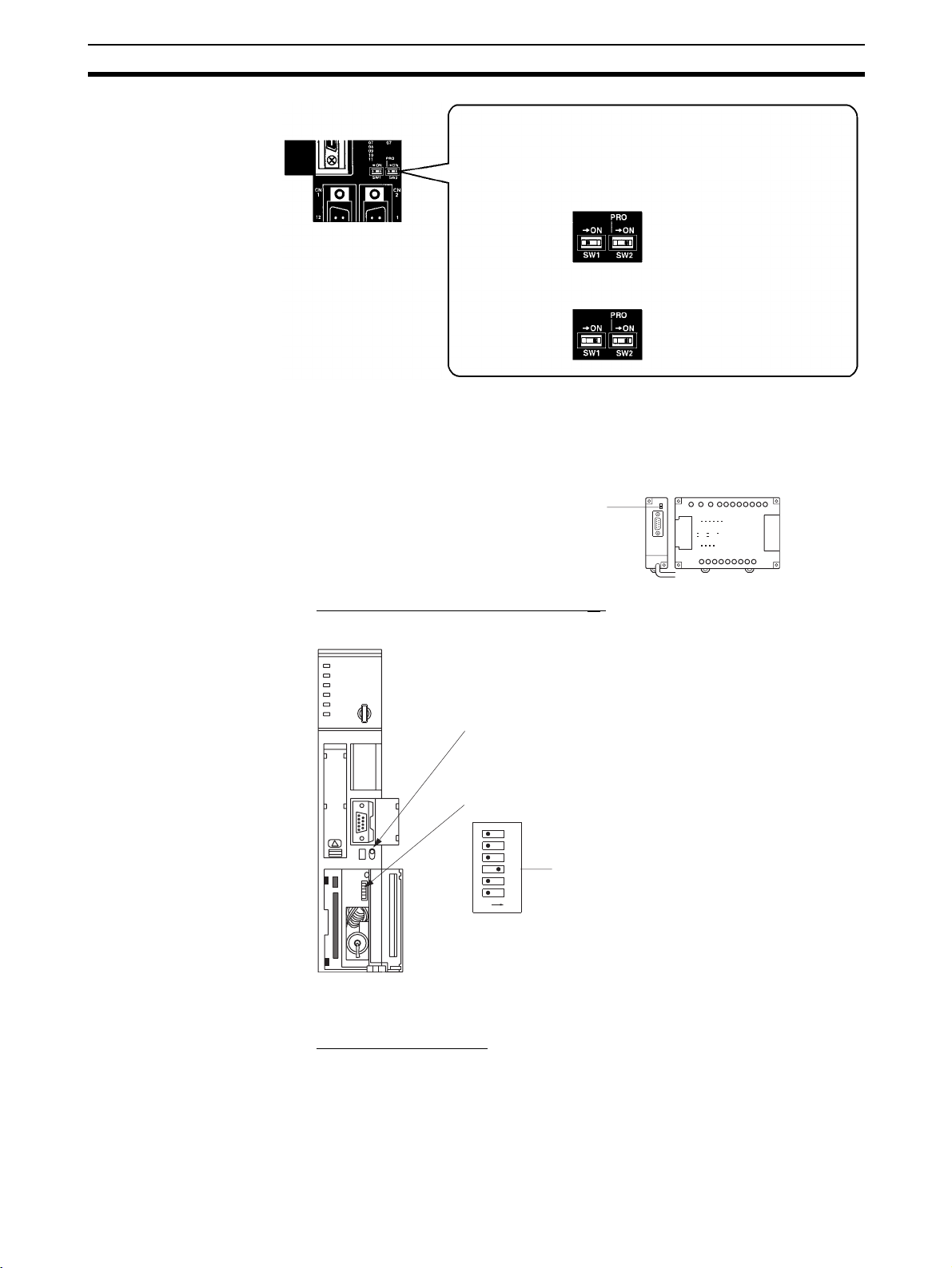
Connecting to the RS-232C Port at the Host Section 4-1
The settings for SW1 and SW2 depend upon the usage of the
peripheral port and RS-232C port.
• Connecting PT to peripheral port
• Connecting PT to built-in RS-232C port
(A device that requires non-standard communications
settings is connected to the peripheral port.)
SW1: OFF
SW2: ON
• Connecting PT to built-in RS-232C port
(A Programming Console is connected to the peripheral
port.)
SW1: OFF
SW2: OFF
Setting the Switches on an RS-232C Adapter
When using a CPM1-CIF01 RS-232C Adapter, set the mode switch as shown
in the following diagram.
CPM1CIF01
Set the mode setting switch to NT (lower position).
Using the NT Link (1:N)
Method
Connecting to CVM1/CV Series (-EV
@)
Set the DIP switches on the front panel as follows.
I/O port selection (selector switch)
Set this to RS-232C.
DIP switch setting (SW3)
6
5
OFF
ON
4
3
2
1
Set SW3 to use NT Link
(ON, right side).
When using a CVM1/CV-series PLC, CPU Unit execution processing (execution control 2) in the PLC Setup must be set to Simultaneous processing.
Compatible Host Units
The OMRON PLCs that can be connected using the NT link (1:N) method are
the CS/CJ-series CPU Units and the C-series C200HX/HG/HE(-Z)E, CQM1H,
and SRM1 only. With the CS/CJ-series PLCs, it is possible to connect a 1:N
NT Link using a Serial Communications Board (CS Series only) or a Serial
Communications Unit.
65
Page 83

Connecting to the RS-232C Port at the Host Section 4-1
Check the model and series of the PLC as well as the model of Serial Communications Board or Unit being used before making the connections.
The hosts that can be connected to the NT631/NT631C by the NT link (1:N)
method using the RS-232C ports of both Units are indicated in the table
below.
PLC Series CPU Units with Built-in NT Link
Function
CS Series CS1G-CPU42/43/44/45-E(V1)
CS1H-CPU63/64/65/66/67-E(V1)
CS1G-CPU42H/43H/44H/45H
CS1H-CPU63H/64H/65H/66H/
67H
CS1D-CPU65H/67H
CJ Series CJ1G-CPU44/45
CJ1G-CPU42H/43H/44H/45H
CJ1H-CPU65H/66H/67H
CJ1M-CPU11/12/13/21/22/23
C Series C200HE-CPU42-(Z)E
C200HG-CPU43-(Z)E
C200HG-CPU63-(Z)E
C200HX-CPU44-(Z)E
C200HX-CPU64-(Z)E
C200HX-CPU65-ZE
C200HX-CPU85-ZE
---
CompoBus/
SRM1-C02-V2 --- SRM1
S Master
Control Unit
CPU Units Connectable with
Communications Board/Unit
CS1G-CPU42/43/44/45-E(V1)
(*1)
CS1H-CPU63/64/65/66/67-E(V1)
CS1G-CPU42H/43H/44H/45H
(*1)
CS1H-CPU63H/64H/65H/66H/
(*1)
67H
CS1D-CPU65H/67H
CJ1G-CPU44/45
CJ1G-CPU42H/43H/44H/45H
CJ1H-CPU65H/66H/67H
CJ1M-CPU11/12/13/21/22/23
C200HE-CPU32-(Z)E
C200HE-CPU42-(Z)E
C200HG-CPU33-(Z)E
C200HG-CPU43-(Z)E
C200HG-CPU53-(Z)E
C200HG-CPU63-(Z)E
C200HX-CPU34-(Z)E
C200HX-CPU44-(Z)E
C200HX-CPU54-(Z)E
C200HX-CPU64-(Z)E
C200HX-CPU65-ZE
C200HX-CPU85-ZE
CQM1H-CPU51
CQM1H-CPU61
(*2)
(*3)
(*3)
(*3)
(*3)
(*4)
(*4)
(*4)
(*4)
(*4)
(*4)
(*4)
(*4)
(*4)
(*4)
(*4)
(*4)
(*5)
(*5)
CS1G
CS1H
(*1)
CS1D
CJ1G
CJ1H
CJ1M
C200HE (-Z)E
C200HG (-Z)E
C200HX (-Z)E
CQM1H
Connectable
to
66
*1
A CS1W-SCB21(-V1) or CS1W-SCB41(-V1) Serial Communications Board
or CS1W-SCU21(-V1) Serial Communications Unit is required.
*2
A CS1W-SCU21(-V1) Serial Communications Unit is required. A CS1WSCB21/41(-V1) Serial Communications Board cannot be used.
*3
One of the following Communications Units is required:
CJ1W-SCU21/41(-V1).
*4
One of the following Communications Boards is required:
C200HW-COM02/COM04/COM05/COM06-E(V1)
*5
A CQM1H-SCB41 Serial Communications Board is required.
Page 84

Connecting to the RS-232C Port at the Host Section 4-1
Reference: Version 1 (-V1) and high-speed versions (H) of the CS-series and CJ-series
CPU Units support the high-speed 1:N NT Link method in addition to the
standard 1:N NT Link method. Furthermore, the high-speed 1:N NT Link
method can be used in earlier versions of CS-series CPU Units by installing
the latest version of a Serial Communications Board or Unit. For details, refer
to Using the High-speed NT Link (1:N) Method (page 70).
Settings at the Host
The Settings required for each Unit are described below.
• Connecting a C-series C200HX/HG/HE(-Z)E, CQM1H, or SRM1
PLC Setup Area Settings
Write the PLC Setup area (data memory) settings directly from a Programming Device (e.g. CX-Programmer) in accordance with the host model and
port.
Connection to Word # Writing
C200HX/HG/HE(-Z)E, SRM1
Built-in RS-232C port
C200HX/HG/HE(-Z)E
Communications Board port A
CQM1H port 1
C200HX/HG/HE(-Z)E
Communications Board port B
*2
Val ue
DM6645 5@00 Use NT link (1:N)
@ = highest unit number of
DM6555
*1
DM6550
*1
the connected PTs (1 to 7)
(*3)
Setting
*1
RS-232C port on the Communications Board
*2
RS-232C port on the Serial Communications Board
*3
When using a C200HE(-Z)E, the maximum PT unit number is 3.
Refer to the PLC’s operation manual for details on changing PLC Setup settings.
Setting the DIP Switches of a C200HX/HG/HE(-Z)E
When using a C200HX/HG/HE(-Z)E, the DIP switches on the front panel must
be set as shown below in order to make the settings in the PLC Setup area
(data memory) effective.
RS-232C port communications condition setting
Set DIP SW5 to OFF to make the settings made in
PLC Setup effective.
Connecting to CS/CJ-series CPU Units
CS/CJ-series CPU Unit: CS1G/H-CPU@@-E(V1), CS1G/H/D-CPU@@H,
CJ1G/M-CPU@@, CJ1G/H-CPU@@H
Connect the PT to the CPU Unit’s built-in RS-232C port. Use a CS1W-CN118
Connecting Cable, however, if connecting the PT to the peripheral port of the
CPU Unit.
PLC Setup Area Settings
When connecting to a CS/CJ-series CPU Unit, set the following communications conditions for the PLC Setup area, in accordance with the communications port to be used.
67
Page 85
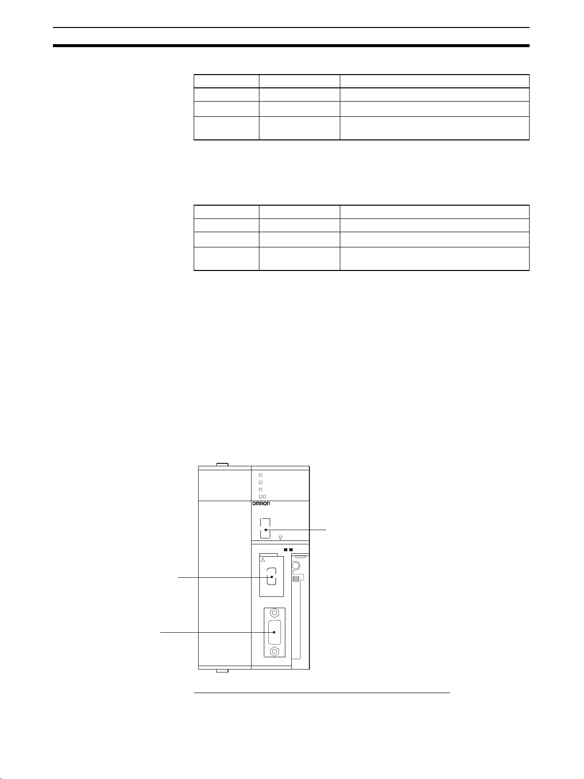
Connecting to the RS-232C Port at the Host Section 4-1
Using the CPU Unit's Built-in RS-232C Port
Word # Writing Value Settings
160 8200 NT link (1:N) mode
161
0000 to 0009
166 000@@ = The largest model number of the con-
*1
Set any value between 0000 and 0009 Hex for the communications baud
rate. The same baud rate will be used regardless of the value as long as it
is between 0000 and 0009 Hex.
Using the CPU Unit's Peripheral Port
Word # Writing Value Settings
144 8200 NT link (1:N) mode
145
0000 to 0009
150 000@@ = The largest model number of the con-
*1
Set any value between 0000 and 0009 Hex for the communications baud
rate. The same baud rate will be used regardless of the value as long as it
is between 0000 and 0009 Hex.
When connecting PT with its model number 0, 2-5 to the built-in RS-232C
port, for example, set the value 8200 Hex to 160 CH, and 0005 Hex to 166CH.
Either set PLC Setup directly from a Programming Device (Programming Console), or transmit the PLC Setup made at a Programming Device (CX-Programmer) to the CPU Unit.
For details on the PLC Setup, refer to the SYSMAC CS Series Operation
Manual (W339) or the SYSMAC CJ Series Operation Manual (W393).
Setting the Front Switches
Set the CPU Unit’s DIP switch to 4 or 5 in accordance with the port NT631/
NT631C is connected to. An example of a CS-series CPU Unit is shown
below.
(*1)
Communications baud rate (standard)
nected PT (0 – 7)
(*1)
Communications baud rate (standard)
nected PT (0 – 7)
68
Peripheral port
This is used mainly for
connection to the
Programming Device.
(This also supports the
RS-232C unit connection.)
RS-232 port
This is used mainly
for connection to the
RS-232C unit.
(This also supports
the CX-Programmer.)
RUN
ERR/ALM
INH
PRPHL/COMM
SYSMAC CS1G
PROGRAMMABLE CONTROLLER
CPU42
DIP switches (inside the battery storage)
• Set SW4 to ON (establishing communications in
accordance with PLC Setup) when connecting the
NT631/NT631C to a peripheral port.
• Set SW5 to OFF (establishing communications in
accordance with PLC Setup) when connecting the
NT631/NT631C to a peripheral port.
MCPWR
OPEN
PERIPHERAL
PORT
OPEN
BUSY
Connecting to CS-series Serial Communications Board
Serial Communications Board equipped with a RS-232C port for CS1-series
CPU Units: CS1W-SCB21(-V1)/41(-V1) (See note.)
Page 86

Connecting to the RS-232C Port at the Host Section 4-1
Note Cannot be used with the CS1D-CPU65H/67H.
CPU Unit Allocation DM Area Settings
Setting is written from the Programming Device (a Programming Console or
CX-Programmer) directly into the allocation DM area (system setting area) of
the CPU Unit. After the setting is written, it becomes effective by turning the
power ON, restarting the Unit, restarting the communications port, or execution of the STUP command.
In the following, the channel numbers of the allocation DM area and settings
are shown.
Allocated DM Area words Setting Setting Contents
Port 1 Por t 2
DM32000 DM32010 8200 1:N NT Link Mode
DM32001 DM32011
0000 to 0009
DM32006 DM32016 000@ @ = The highest unit number of the
*1
Set any value between 0000 and 0009 hex for the baud rate. The same
baud rate will be used regardless of the value as long as it is between 0000
and 0009 hex.
When connecting PTs with model numbers 3 to 6 to port 1, for example, set
the value 8200 hex to DM32000, 0000 hex to DM32001, and 0006 hex to
DM32006.
(*1)
Baud rate (standard)
connected PTs (0 to 7)
Connecting to CS/CJ-series Serial Communications Unit
A CS/CJ-series Rack-mounting Unit: CS1W-SCU21,
CJ1W-SCU21(-V1)/41(-V1)
Setting the Front Switches
Set the unit number of the Serial Communications Unit by using the rotary
switch located on the front panel. Set each switch with a flat blade screwdriver
so that the values or symbols in the setting value window agree with the following.
SCU21
RUN
ERC
SD1
RD1
UNIT
No.
RDY
ERH
SD2
RD2
F
0
E
1
D
2
3
4
B
5
A
6
9
7
8
Set the unit number to 0 through F so
C
that it will not overlap with the numbers
used in other units.
Allocation DM Area Settings for CPU Unit
Setting is written from the Programming Device (a Programming Console or
CX-Programmer) directly into the allocation DM area (system setting area) of
the CPU Unit. After the setting is written, it becomes effective by turning the
power ON, restarting the Unit, restarting the communications port, or execution of the STUP command.
In the following, the channel numbers of the allocation DM area and settings
are shown.
m=DM30000+100*unit number (CH)
Allocated DM Area words Setting Setting Contents
Port 1 Por t 2
m m+10 8200 1:N NT Link Mode
m+1 m+11
0000 to 0009
m+6 m+16 000@ @ = The highest unit number of the
(*1)
Baud rate (standard)
connected PTs (0 to 7)
69
Page 87

Connecting to the RS-232C Port at the Host Section 4-1
*1
Set any value between 0000 and 0009 hex for the baud rate. The same
baud rate will be used regardless of the value as long as it is between 0000
and 0009 hex.
Using the High-speed NT
Link (1:N) Method
PLC Series CPU Units with Built-in NT
CS Series
CJ Series CJ1G-CPU44/45
Compatible Host Units
The high-speed 1:N NT Link method can be used with version 1 (-V1) and
high-speed versions (H) of the CS-series and CJ-series CPU Units. Furthermore, the high-speed 1:N NT Link method can be used in earlier versions of
CS-series and CJ-series CPU Units by installing the latest version of a Serial
Communications Board (CS Series only) or Serial Communications Unit.
Be sure to check the model number of the PLC and Serial Communications
Board/Unit before trying to establish the high-speed 1:N NT Link.
The following table shows which CS-series PLCs can be connected to an
NT631/NT631C with the high-speed 1:N NT Link.
Link Function
CS1G-CPU42/43/44/45-EV1
CS1H-CPU63/64/65/66/67-
(*1)
EV1
CS1G-CPU42H/43H/44H/45H
CS1H-CPU63H/64H/65H/66H/
67H
CS1D-CPU65H/67H
CJ1G-CPU42H/43H/44H/45H
CJ1H-CPU65H/66H/67H
CJ1M-CPU11/12/13/21/22/23
(*1)
CPU Units Connectable with
Communications Board/Unit
CS1G-CPU42/43/44/45-E(V1)
CS1H-CPU63/64/65/66/67-
(*2)
E(V1)
CS1G-CPU42H/43H/44H/45H
CS1H-CPU63H/64H/65H/66H/
(*2)
67H
CS1D-CPU65H/67H
CJ1G-CPU44/45
CJ1G-CPU42H/43H/44H/45H
CJ1H-CPU65H/66H/67H
CJ1M-CPU11/12/13/21/22/23
(*3)
(*4)
(*4)
(*4)
(*4)
(*2)
(*2)
CS1G
CS1H
CS1D
CJ1G
CJ1H
CJ1M
Connectable to
*1
The high-speed 1:N NT Link is not supported in a direct connection to the
CPU Unit of a CS1-series PLC without the -V1 suffix.
*2
A CS1W-SCB21 or CS1W-SCB41(-V1) Serial Communications Board or
CS1W-SCU21(-V1) Serial Communications Unit is required.
*3
A CS1W-SCU21(-V1) Serial Communications Unit is required.
A CS1W-SCB21/41(-V1) Serial Communications Board cannot be used.
*4
One of the following Communications Units is required:
CJ1W-SCU21/41(-V1).
Settings at the Host
The Settings required for each Unit are described below.
• Connecting CS/CJ-series CPU Units
CS/CJ-series CPU Unit: CS1G/H-CPU@@-EV1, CS1G/H/D-CPU@@H-E,
CJ1G/M-CPU@@-E, CJ1GH-CPU@@H-E
Connect the PT to the CPU Unit’s built-in RS-232C port. Use a CS1W-CN118
Connecting Cable, however, if connecting the PT to the peripheral port of the
CPU Unit.
PLC Setup
When connecting to a CS-series CPU Unit, set the following communications
conditions for the PLC Setup area, in accordance with the communications
port to be used.
70
Page 88
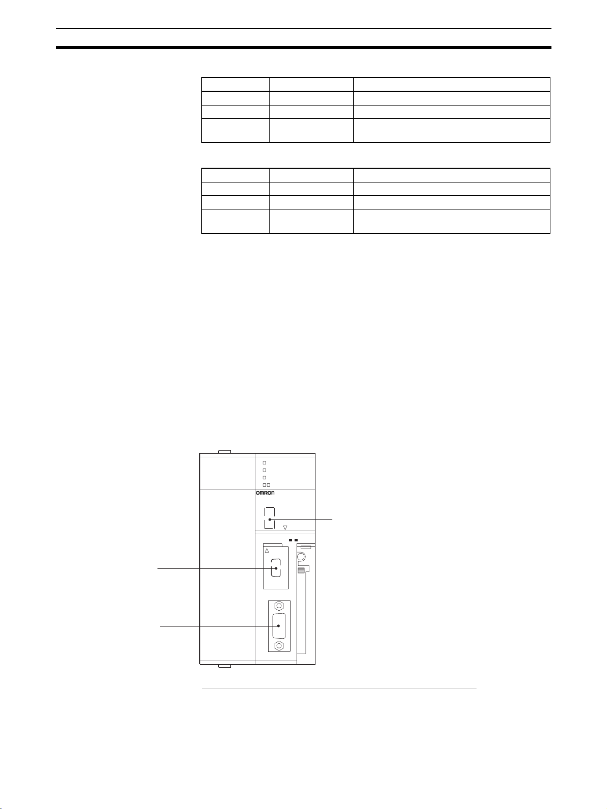
Connecting to the RS-232C Port at the Host Section 4-1
Using the CPU Unit's Built-in RS-232C Port
Word # Setting Setting Contents
160 8200 1:N NT Link Mode
161 000A Baud rate (standard)
166 000@ @ = The highest unit number of the connected
PTs (0 to 7)
Using the CPU Unit's Peripheral Port
Word # Setting Setting Contents
144 8200 1:N NT Link Mode
145 000A Baud rate (standard)
150 000@ @ = The highest unit number of the connected
When connecting PTs with model numbers 0, 2, 3, 4, and 5 to the built-in RS232C port, for example, set the value 8200 hex to word 160, 000A hex to word
161, and 0005 hex to word 166.
Either set PLC Setup directly from a Programming Device (Programming Console), or transmit the PLC Setup made at a Programming Device (CX-Programmer) to the CPU Unit.
For details on the PLC Setup, refer to the SYSMAC CS Series Operation
Manual (W339) or the SYSMAC CJ Series Operation Manual (W393).
PTs (0 to 7)
Reference: When using the CX-Programmer to set the high-speed 1:N NT Link, set the
Peripheral port
This is used mainly for
connection to the
Programming Device.
(This also supports
connection of RS-232C
devices.)
RS-232 port
This is used mainly for
connection of RS-232C
devices.
(This also supports connection
of the CX-Programmer.)
communications baud rate to 115,200 bps.
Setting The Front Switches
Set the CPU Unit’s DIP switch to 4 or 5 in accordance with the port NT631/
NT631C is connected to. An example of a CS-series CPU Unit is shown
below.
RUN
ERR/ALM
INH
PRPHL/COMM
SYSMAC CS1G
PROGRAMMABLE CONTROLLER
CPU42
DIP switches (inside the battery storage)
• Set SW4 to ON (establishing communications in
accordance with PLC Setup) when connecting the
NT631/NT631C to the peripheral port.
• Set SW5 to OFF (establishing communications in
accordance with PLC Setup) when connecting
the NT631/NT631C to the RS-232C port.
MCPWR
OPEN
PERIPHERAL
PORT
OPEN
BUSY
Connecting to a CS-series Serial Communications Board
Serial Communications Board equipped with a RS-232C port for CS-series
CPU Units: CS1W-SCB21(-V1)/41(-V1)
Note Cannot be used with the CS1D-CPU65H/67H.
71
Page 89

Connecting to the RS-232C Port at the Host Section 4-1
Reference: CS-series Serial Communications Boards and Units with lot number 991220
(12/20/99) and later support the high-speed 1:N NT Link. Boards and Units
with earlier lot numbers cannot be used.
CPU Unit Allocation DM Area Settings
Setting is written from the Programming Device (a Programming Console or
CX-Programmer) directly into the allocation DM area (system setting area) of
the CPU Unit. After the setting is written, it becomes effective by turning the
power ON, restarting the Unit, restarting the communications port, or execution of the STUP command.
In the following, the channel numbers of the allocation DM area and settings
are shown.
Allocated DM Area words Setting Setting Contents
Port 1 Por t 2
DM32000 DM32010 8200 1:N NT Link Mode
DM32001 DM32011 000A Baud rate (standard)
DM32006 DM32016 000@ @ = The highest unit number of the con-
For example, when connecting PTs with model numbers 3, 4, 5, and 6 to port
1, set the value 8200 hex to DM32000, 000A hex to DM32001, and 0006 hex
to DM32006.
nected PTs (0 to 7)
Connecting to a CS/CJ-series Serial Communications Unit
A CS/CJ-series Rack-mounting Unit: CS1W-SCU21(-V1),
CJ1W-SCU21(-V1)/41(-V1)
Reference: CS-series Serial Communications Boards and Units with lot number 991220
(12/20/99) and later support the high-speed 1:N NT Link. Boards and Units
with earlier lot numbers cannot be used.
Setting the Front Switches
Set the unit number of the Serial Communications Unit by using the rotary
switch located on the front panel. Set each switch with a flat blade screwdriver
so that the values or symbols in the setting value window agree with the following.
SCU21
RUN
ERC
SD1
RD1
UNIT
No.
RDY
ERH
SD2
RD2
F
0
E
1
D
2
3
C
4
B
5
A
6
9
7
8
Set the unit number to 0 through F so
that it will not overlap with the numbers
used in other units.
Allocation DM Area Settings for CPU Unit
Setting is written from the Programming Device (a Programming Console or
CX-Programmer) directly into the allocation DM area (system setting area) of
the CPU Unit. After the setting is written, it becomes effective by turning the
power ON, restarting the Unit, restarting the communications port, or execution of the STUP command.
In the following table, the channel numbers of the allocation DM area and settings are shown.
72
Page 90

Connecting to the RS-232C Port at the Host Section 4-1
Word m = DM30000 + (100 × unit number)
Allocated DM Area words Setting Setting Contents
Port 1 Por t 2
m m+10 8200 1:N NT Link Mode
m+1 m+11 000A Baud rate (standard)
m+6 m+16 000@ @ = The highest unit number of the con-
nected PTs (0 to 7)
When Using the Memory
Link Method
In the memory link method, the connection can be made to a personal computer with RS-232 and an FA computer, etc.
When connecting to the host in the memory link method, it is necessary to
create a program for the memory link at the host side.
The following are the communications conditions that can be used in the
memory link method. For the host (a personal computer, an FA computer,
etc.), its setting should be compatible to one of the communications conditions listed in the following table. Set the same communications conditions at
the NT631/NT631C by the memory switch. (page 160).
Item Settings at the host
Input/Output port RS-232C
Communications speed 1200, 2400, 4800, 9600, 19200, 38400 bps.
Data bits length 7 bits, 8 bits
Stop bits length 1 bits, 2 bits
Parity None, even, odd
Flow control None, RS/CS, XON/XOFF
4-1-2 Connecting Directly between RS-232C Ports
The method for connection between the RS-232C ports of the NT631/
NT631C and the host is described here.
NT631/NT631C
RESET
RD
TRM
RDB
SDA
SDB
CSA
CSB
24V
+DC
9-pin connector
PRINTERPORTB
PORTA
Serial port A or B
(RS-232C, 9-pin type)
Cable with RS-232C connectors
Host Link Unit or CPU Unit
SYSMAC
CS/CJ-series PLC,
C-series PLC,
CVM1/CV-series PLC,
SRM1
9-pin connector
or
25-pin connector
Recommended Connector Cable
When making the connector cable, as far as possible use the recommended
connectors, connector hoods, and cables indicated in the table below. Some
Units come supplied with one connector and one connector hood.
73
Page 91

Connecting to the RS-232C Port at the Host Section 4-1
Check the required components and prepare them in advance.
Name Model Remarks Delivered with
Connector XM2A-0901 9-pin
Made by OMRON
XM24-2501 25-pin
Made by OMRON
DB-25P 25-pin
Made by JAE
Connector
hood
Cable AWG28×5P
XM2S-0911 9-pin
Made by OMRON
XM2S-0913 9-pin
XM2S-0911-E 9-pin
XM2S-2511 25-pin
DB-C2-J9 25-pin
IFVV-SB
CO-MA-VV-SB
5P×28AWG
Made by OMRON
Made by OMRON
Made by OMRON
Made by JAE
Multi-core shielded cable
Made by Fujikura, Ltd.
Multi-core shielded cable
Made by Hitachi Cable,
Ltd.
CS-series CS1G/CS1H/
CS1D,
CJ-series CJ1G/CJ1H/
CJ1M,
C-series CQM1,
C200HS,
C200HX/HG/HE(-Z)E,
CVM1/CV-series CPU
Units
CV500-LK201
C500-LK203
CV500-LK201
C200H-LK201-EV1
3G2A5-LK201-EV1
3G2A6-LK201-EV1
C-series CQM1,
C200HS,
C200HX/HG/HE(-Z)E,
CVM1/CV-series CPU
Units
CV500-LK201
CS-series CS1G/CS1H/
CS1D,
CJ-series CJ1G/CJ1H/
CJ1M
C500-LK203
CV500-LK201
C200H-LK201-EV1
3G2A5-LK201-EV1
3G2A6-LK201-EV1
74
Note After connecting a communications cable, always secure it with the screws.
OMRON Cables with Connectors
When a connection is made at serial port A in other than the memory link
method, OMRON cables with connectors shown below are available.
Model Cable Length Connector Specification
XW2Z-200S 2 m 9-pin ⇔ 25 pin
XW2Z-500S 5 m
XW2Z-200T 2 m 9-pin ⇔ 9-pin
XW2Z-500T 5 m
Page 92
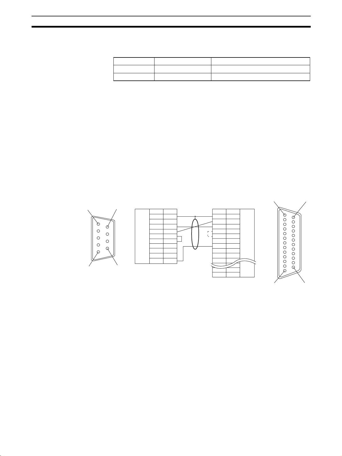
Connecting to the RS-232C Port at the Host Section 4-1
When a connection is made to a personal computer at serial port A in the
memory link method, OMRON cable with connectors shown below are available.
Model Cable Length Connector Specification
CV500-CN228 2 m 9-pin ⇔ 25 pin
XW2Z-S002 2 m 9-pin ⇔ 9 pin
Note The cable’s tensile load is 30 N. Do not subject it to loads greater than this.
Wiring for a Host Link Unit
(25-pin) Connection
1
5
Applicable Units: C200H-LK201-EV1
3G2A5-LK201-EV1
C500-LK203
3G2A6-LK201-EV1
CV500-LK201 (communications port 1)
Cables with connectors that can be used at serial port A:
XW2Z-200S (9-pin
XW2Z-500S (9-pin
⇔ 25-pin, 2 m)
⇔ 25-pin, 5 m)
CVM1/CV-series Host Link Units (CV500-LK201) have two types of connector; a 25-pin connector (communications port 1), and a 9-pin connector (communications port 2). When using communications port 2, refer to Wiring for
Other Connections (Other Than the Memory Link Method) (page 75).
Serial Port A, B
6
9
NT631/NT631C
Abbreviation
FG
SD
RS-232C
interface
RD
RS
CS
+5V
SG
(9-pin type)
Pin
number
Connector
hood
1
2
3
4
5
6
7
8
9
Shielding wire
PLC (host link unit)
Pin
Abbreviation
number
1
FG
2
SD
3
RD
RS
4
5
CS
-
6
*
7
SG
8
-
-
-
-
-
-
-
-
ER
RS-232C
interface
(25-pin type)
114
13 25
Wiring for Other
Connections
* For Units that have a CTS setting selector switch, RS and CS do not have
to be shorted if this switch is set to 0 V.
Applicable Units:
CV500-LK201 (communications port 2)
CS1W-SCU21(-V1)
CJ1W-SCU21(-V1) CJ1W-SCU41(-V1)
CPM1-10CDR-@ CPM1-20CDR-@
CPM1A-10CD@-@ CPM1A-20CD@-@
CPM1A-30CD@-@ CPM1A-40CD@-@
CPM2A-30CD@@-@ CPM2A-40CD@@-@
CPM2A-60CD@@-@
CPM2C-10@@@@@@-@ CPM2C-20@@@@@@-@
CQM1-CPU21-E
CQM1-CPU41-EV1 CQM1-CPU42-EV1
CQM1-CPU43-EV1 CQM1-CPU44-EV1
CQM1H-CPU11 CQM1H-CPU21
CQM1H-CPU51 CQM1H-CPU61
75
Page 93
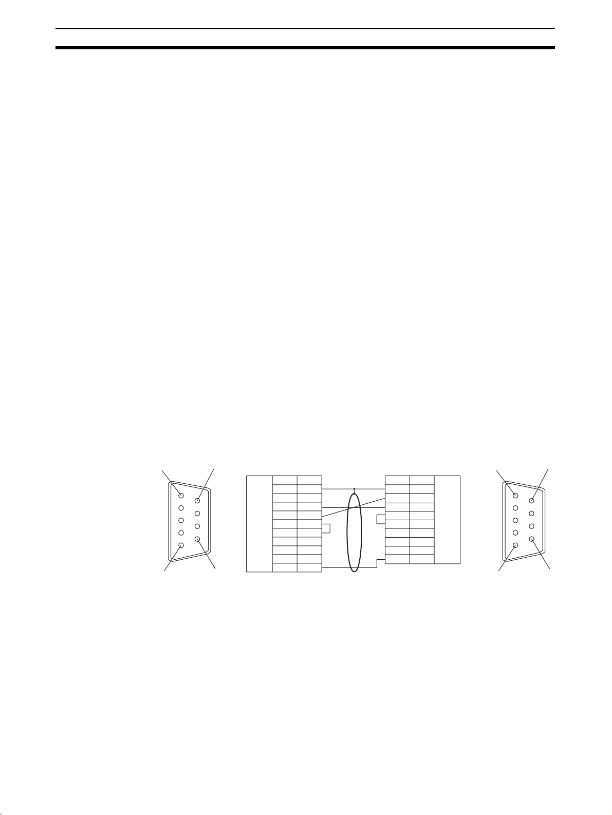
Connecting to the RS-232C Port at the Host Section 4-1
CS1G-CPU42/43/44/45-E(V1)
CS1H-CPU63/64/65/66/67-E(V1)
CS1G-CPU42H/43H/44H/45H
CS1H-CPU63H/64H/65H/66H/67H
CS1D-CPU65H/67H
CJ1G-CPU44/45
CJ1G-CPU42H/43H/44H/45H
CJ1H-CPU65H/66H/67H
CJ1M-CPU11/12/13/21/22/23
C200HS-CPU21-E, -EC C200HS-CPU23-E
C200HS-CPU31-E C200HS-CPU33-E
C200HE-CPU32-(Z)E C200HE-CPU42-(Z)E
C200HG-CPU33-(Z)E C200HG-CPU43-(Z)E
C200HG-CPU53-(Z)E C200HG-CPU63-(Z)E
C200HX-CPU34-(Z)E C200HX-CPU44-(Z)E
C200HX-CPU54-(Z)E C200HX-CPU64-(Z)E
C200HX-CPU65-ZE C200HX-CPU85-ZE
CV500-CPU01-EV1 CV1000-CPU01-EV1
CV2000-CPU01-EV1
CVM1-CPU01-EV2 CVM1-CPU11-EV2
CVM1-CPU21-EV2
SRM1-C02-V2
Cables with connectors that can be used at serial port A:
XW2Z-200T (9-pin
XW2Z-500T (9-pin
CPU Units of CVM1/CV-series PLCs without the suffix -EV@ cannot be connected by any connection method.
When connecting to the peripheral port of a CS/CJ-series CPU Unit, a CS1WCN118 Connecting Cable is required in addition to the above cables.
⇔ 9-pin, 2 m)
⇔ 9-pin, 5 m)
1
5
Wiring for a Memory Link
Connection
Serial Port A, B
6
9
NT631/NT631C PLC (Host link unit)
RS-232C
interface
Abbreviation
FG
-
SD
RD
RS
CS
+5V
-
-
SG
Pin
number
Connector
hood
1
2
3
4
5
6
7
8
9
Shielding wire
Pin
number
Connector
hood
2
3
4
5
6
7
8
9
(9-pin type)
Abbreviation
FG
SD
RD
RS
CS
-
-
-
SG
RS-232C
interface
(9-pin type)
1
Cables with connectors that can be used:
CV500-CN228 (9-pin
XW2Z-S002 (9-pin
⇔25-pin, 2 m)
⇔9-pin, 2 m)
Serial Port A, B
Prepare the adapter cable while referring to the following diagram.
6
5
9
76
Page 94

Connecting to the RS-232C Port at the Host Section 4-1
NT631/NT631C
1
5
6
RS-232C
interface
9
(9-pin type)
Abbreviation
FG
−
SD
RD
RS
CS
+5V
−
−
SG
Pin
number
Connector
hood
1
2
3
4
5
6
7
8
9
Shielding wire
Host side
Abbreviation
Connector
hood
SD
RD
RS
CS
SG
RS-232C
interface
77
Page 95

Connecting to the RS-232C Port at the Host Section 4-1
78
Page 96

SECTION 5
Connecting to the Host from the RS-422A/485 Port
This section describes the method for connecting to the host using the RS-422A/485 port of the PT.
5-1 Connecting to the Host’s RS-232C Port. . . . . . . . . . . . . . . . . . . . . . . . . . . . . 80
5-1-1 The Type of Host and Settings. . . . . . . . . . . . . . . . . . . . . . . . . . . . . 81
5-1-2 1:1 Connection between RS-422A/485 at the PT and RS-232C
at the Host . . . . . . . . . . . . . . . . . . . . . . . . . . . . . . . . . . . . . . . . . . . . 82
5-1-3 1:N Connection between RS-422A/485 at the PT and RS-232C
5-1-4 Recommended Connectors, Cables, and Crimp Terminals . . . . . . . 90
5-1-5 Setting the Terminal Resistance for RS-422A/485 Communications 92
5-2 Connecting to the Host’s RS-422A/485 Port . . . . . . . . . . . . . . . . . . . . . . . . . 93
5-2-1 Host Types and Settings . . . . . . . . . . . . . . . . . . . . . . . . . . . . . . . . . . 94
5-2-2 Direct Connection between RS-422A Ports at Both Units . . . . . . . 115
5-2-3 Direct Connection between RS-485 Ports at Both Units . . . . . . . . . 118
5-2-4 1:N Connection among RS-422A Ports. . . . . . . . . . . . . . . . . . . . . . 119
5-2-5 1:N Connection among RS-485 Ports . . . . . . . . . . . . . . . . . . . . . . . 121
5-2-6 Recommended Connectors, Cables and Crimp Terminals. . . . . . . . 123
5-2-7 Setting the Terminal Resistance for RS-422A/485 Communications 124
5-2-8 Handling the Shield on RS-422A/485 Cables . . . . . . . . . . . . . . . . . 125
at the Host . . . . . . . . . . . . . . . . . . . . . . . . . . . . . . . . . . . . . . . . . . . . 86
79
Page 97
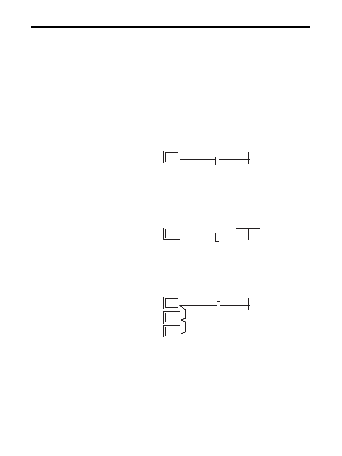
Connecting to the Host’s RS-232C Port Section 5-1
(
)
5-1 Connecting to the Host’s RS-232C Port
The methods for connecting the RS-422A/485 port of the NT631/NT631C and
the RS-232C port of the host are described here. There are the following
methods.
The following discussion is focused on the connection method to OMRON
PLCs (By using the memory link method, a connection can be made to any
arbitrary RS-232 unit). When making a connection to a host other than
OMRON PLCs, refer to the PLC Connection Manual (V042-E1-@) or NT31/
631 Multi Vendor Connection Manual (V060-E1-@).
• Method in which the RS-422A port of the NT631/NT631C and the RS232C port of the host are connected in a 1:1 connection via an RS-232C/
RS-422A Adapter (page 82).
When this method is used, the cable length can be extended up to
500 m.
PT Host
RS-422A cable
(max. 500 m)
• Method in which the RS-485 port of the NT631/NT631C and the RS-232C
port of the host are connected in a 1:1 connection via an RS-232C/RS422A Adapter (page 82).
When this method is used, the cable length can be extended up to
500 m. This connection method can be used only with the NT Link
(1:N) method of type RS-485.
PT Host
RS-485 cable
(max. 500 m)
RS-232C/RS-422A
convertor unit
RS-232C
cable
max. 2 m
RS-232C/RS-422A
convertor unit
RS-232C
cable
(max. 2 m)
• Method in which the RS-422A ports of multiple NT631/NT631Cs and the
RS-232C port of the host are connected in a 1:N connection via an RS232C/RS-422A Adapter (page 86).
This connection method is used with the RS-422A NT Link (1:N) method.
PT Host
RS-232C/RS422A
convertor unit
RS-422A cable
(max. total length
500 m)
RS-232C
cable
(max. 2 m)
• Method in which the RS-485 ports of multiple NT631/NT631Cs and the
RS-232C port of the host are connected in a 1:N connection via an RS232C/RS-422A Adapter (page 86).
This connection method is used with the RS-485 NT Link (1:N) method
(standard or high-speed).
80
Page 98
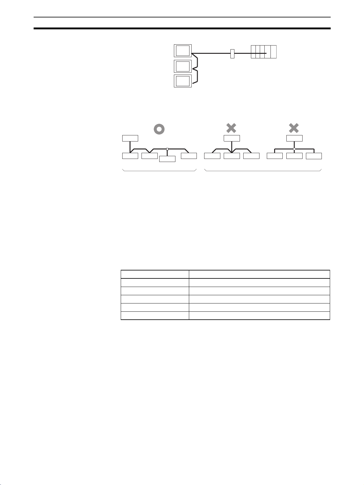
Connecting to the Host’s RS-232C Port Section 5-1
k
PT Host
RS-232C/RS422A
convertor unit
RS-485 cable
(max. total length
500 m)
RS-232C
cable
(max. 2 m)
Note One end of the wire must always be connected to the host (PLC), and there
must be no branching. Branching will cause problems such as transmission
delays and communications failures.
PLC
(At termination)
Relay terminal block Relay terminal bloc
NT631C
(Not at
termination)
(Not at
termination)
Example of Good Connection Examples of Bad Connections
Max. 2 m
NT631
(Not at
termination)
(At
termination)
PLC
NT631C NT631CNT631 NT631 NT631 NT631 NT631
PLC
NT631
Reference: CS/CJ-series CPU Units cannot be connected with the 1:1 connection NT
Link method. Use the 1:N connection NT Link method (standard or highspeed) instead to make the 1:1 connection. For details, refer to Using the NT
Link (1:N) Method (page 65) or Using the High-speed NT Link (1:N) Method
(page 70).
5-1-1 The Type of Host and Settings
The using condition is the same as the connecting PT side RS-232C and the
host side RS-232C.
For the available type and settings of the host, refer to the pages listed below.
Method Reference
Host link Host Link Method (page 48)
NT Link (1:1) NT Link (1:1) method (page 61)
NT Link (1:N) Using the NT Link (1:N) Method (page 65)
High-speed NT Link (1:N) Using the High-speed NT Link (1:N) Method (page 70)
Memory link Memory Link Method (page 73)
Settings at the RS-232C/
RS-422A Adapter (NTAL001)
When making a connection between RS-232C and RS-422A/485 ports using
an RS-232C/RS-422A Adapter, set the DIP switches on the NT-AL001 as follows.
81
Page 99
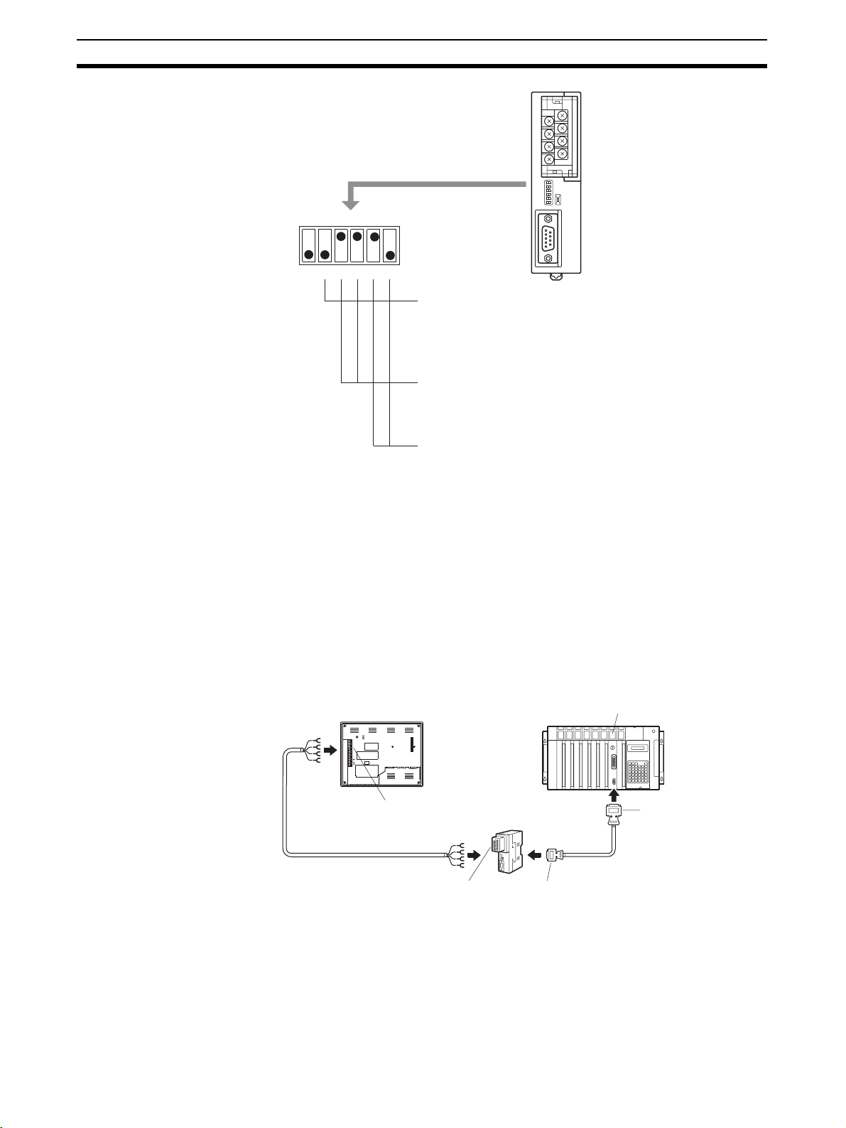
Connecting to the Host’s RS-232C Port Section 5-1
Example: the terminal resistor is active,
RS-422A, NT Link (1:N).
ON
12345 6
om on
R
NT-AL001
Built-in terminal resistor setting (DIP SW1-2)
If at the end of the RS-422A/485 cable, set this switch
to ON (to activate the built-in terminal resistor).
If not at the end of the RS-422A/485 cable, set this
switch to OFF (to inactivate the built-in terminal
resistor).
2-wire type/4-wire type selection (DIP SW1-3, SW1-4)
For RS-422A, set both of these switches to OFF (4-wire type).
For RS-485, set both of these switches to ON (2-wire type).
Selection of RS-422A/485 send mode (DIP SW1-5, SW1-6)
For host link or NT Link (1:1), set both of these switches to
OFF. (Always send)
For NT Link (1:N), set SW1-5 to OFF and SW1-6 to ON.
(Sends when CS is H)
Note Read the manual supplied with the NT-AL001 carefully before using the Unit.
5-1-2 1:1 Connection between RS-422A/485 at the PT and RS-232C at
the Host
The connection method in which the RS-422A/485 port of an NT631/NT631C
and the RS-232C port of a host are connected via a Adapter is described
here.
An RS-232C/RS-422A Adapter (NT-AL001) is used to convert between the
RS-232C and RS-422A communications methods.
NT631/NT631C
RESET
RDA
TRM
RDB
SDA
SDB
CSA
CSB
24V
PRINTERPORTB
+DC
Serial port B
(RS-422A/485,
terminal block)
RS-422A/485 cable
(max. length: 500 m)
RS-422A terminal block
PORTA
RS-232C/RS-422A
convertor unit
(NT-AL001)
RS-232C cable
with connectors
9-pin connector
Host Link Unit or CPU Unit
SYSMAC
CS/CJ-series PLC
C-series PLC,
CVM1/CV-series PLC,
SRM1
9-pin connector or
25-pin connector
82
Page 100

Connecting to the Host’s RS-232C Port Section 5-1
8
6
4
Reference: When using RS-485 as a port for the NT631/NT631C, only NT Link (1:N)
method (standard or high-speed) can be used.
Connecting an NT631/NT631C and NT-AL001 (RS-422A)
NT631/NT631C
NT-AL001
RS-422A
Host
RDA
TRM
RDB
SDA
SDB
RSA
RSB
NT631/NT631C side
RS-422A/
485
terminal
block
24V
+DC
Abbreviation
RDA (-)
TRM
RDB (+)
SDA (-)
SDB (+)
RSA (-)
RSB (+)
Functional
ground
For details on handling shield wires, refer to 5-2-8 Handling the Shield on RS-
422A/485 Cables on page 125.
Connecting an NT631/NT631C and NT-AL001 (RS-485)
NT631/NT631C
RS-485
RDA
TRM
RDB
SDA
SDB
RSA
RSB
NT631/NT631C side
Abbreviation
RDA (-)
TRM
RDB (+)
RS-422A/
485
SDA (-)
terminal
block
SDB (+)
RSA (-)
RSB (+)
Functional
ground
Short-circuit
tool
Shielding wire
NT-AL001
Short-circuit
tool
Shielding wire
NT-AL001 side
Pin number
6
5
4
3
1
Host
NT-AL001 side
Pin number
6
5
4
3
1
Abbreviation
RDA (-)
RDB (+)
SDA (-)
SDB (+)
Functional
ground
Abbreviation
RDA (-)
RDB (+)
SDA (-)
SDB (+)
Functional
ground
RS-422A
terminal
block
RS-422A
terminal
block
7
5
3
1
7
5
3
1
2
8
6
4
2
For details on handling shield wires, refer to 5-2-8 Handling the Shield on RS-
422A/485 Cables on page 125.
Reference: When using RS-485 as a port for the NT631/NT631C, only NT Link (1:N)
method (standard or high-speed) can be used.
Connecting an NT-AL001 and Host
24V
+DC
NT631/NT631C
NT-AL001
Host
RS-232C
83
 Loading...