

Page 1

&DW1R9(
1%VHULHV
1%47:%
1%47:%
1%:7:%
1%:7:%
3URJUDPPDEOH7HUPLQDOV
HOST CONNECTION
MANUAL
Page 2

NOTE
All rights reserved. No part of this publication may be reproduced, stored in a retrieval system, or transmitted, in
any form, or by any means, mechanical, electronic, photocopying, recording, or otherwise, without the prior
written permission of OMRON.
No patent liability is assumed with respect to the use of the information contained herein. Moreover, because
OMRON is constantly striving to improve its high-quality products, the information contained in this manual is
subject to change without notice. Every precaution has been taken in the preparation of this manual. Nevertheless, OMRON assumes no responsibility for errors or omissions. Neither is any liability assumed for damages
resulting from the use of the information contained in this publication.
Trademarks
• Sysmac and SYSMAC are trademarks or registered trademarks of OMRON Corporation in Japan and other
countries for OMRON factory automation products.
• Microsoft, Windows, Windows Vista, and Excel are either registered trademarks or trademarks of Microsoft
Corporation in the United States and other countries.
• EtherCAT® is registered trademark and patented technology, licensed by Beckhoff Automation GmbH, Germany.
• ODVA, CIP, CompoNet, DeviceNet, and EtherNet/IP are trademarks of ODVA.
• The SD and SDHC logos are trademarks of SD-3C, LLC.
Other company names and product names in this document are the trademarks or registered trademarks of their
respective companies.
Copyrights
Microsoft product screen shots reprinted with permission from Microsoft Corporation.
Page 3

NB-series
NB3Q-TWB
NB5Q-TWB
NB7W-TWB
NB10W-TW01B
Programmable Terminals
Host Connection Manual
Revised July 2017
Page 4

Page 5

Introduction
Thank you for purchasing an NB-series Programmable Terminal.
NB-Series Programmable Terminals (PTs) are designed to handle information generated in FA
production sites. Be sure to understand the functions and performances etc thoroughly before using PT
correctly.
Intended Audience
This manual is intended for the following personnel, who must also have knowledge of electrical
systems (an electrical engineer or the equivalent).
• Personnel in charge of introducing FA systems into production facilities.
• Personnel in charge of designing FA systems.
• Personnel in charge of installing and connecting FA facilities.
• Personnel in charge of managing FA systems and facilities
Introduction
General Precautions
• The user must operate the product according to the performance specifications described in the
operation manuals.
• Do not use the PT touch switch input functions for applications where danger to human life or serious
property damage is possible, or for emergency switch applications.
• Before using the product under conditions which are not described in the manual or applying the
product to nuclear control systems, railroad systems, aviation systems, vehicles, combustion
systems, medical equipment, amusement machines, safety equipment, and other systems,
machines and equipment that may have a serious influence on lives and property if used improperly,
consult your OMRON representative.
• Make sure that the ratings and performance characteristics of the product are sufficient for the
systems, machines, and equipment, and be sure to provide the systems, machines, and equipment
with double safety mechanisms.
• This manual provides information for connecting and setting up an NB-Series PT. Be sure to read
this manual before attempting to use the PT and keep this manual close at hand for reference during
installation and operation.
NB-series Programmable Terminals Host Connection Manual (V108)
1
Page 6

NB-series Manuals
NB-series Manuals
NB-series manuals are organized in the sections listed in the following tables. Refer to the appropriate
section in the manuals as required.
Programmable Terminals Host Connection Manual (Cat. No. V108)
(This Manual)
Section Contents
Section 1 List for All PLCs
Supported by NB series
Section 2 Connecting to SIEMENS
PLCs
Section 3 Connecting to Mitsubishi
PLCs
Section 4 Connecting to Schneider
PLCs
Section 5 Modbus Connection This section describes the connection on Modbus protocol.
Section 6 Connecting to Delta PLCs This section describes the connection to Delta PLCs.
Section 7 Connecting to LSIS PLCs This section describes the connection to LSIS PLCs.
Section 8 Connecting to Panasonic
Industrial Devices SUNX PLCs
Section 9 Connecting to AllenBradley (Rockwell) PLC
Section 10 Connecting to PLC of GE
Fanuc Automation Inc.
Section 11 Connecting to Keyence
PLCs
This section lists all PLCs supported by NB Units.
This section describes the connection to SIEMENS PLCs.
This section describes the connection to Mitsubishi PLCs.
This section describes the connection to Schneider PLCs.
This section describes the connection to Panasonic Industrial Devices
SUNX PLCs.
This section describes the connection to Allen-Bradley PLC.
This section describes the connection to PLC of GE Fanuc Automation
Inc.
This section describes methods to connect to Keyence PLCs.
Programmable Terminals NB-Designer Operation Manual
(Cat. No. V106)
Section Contents
Section 1 Introduction This section provides an outline of the NB-series PTs, including their
functions, features, connection types and communication methods.
Section 2 Installation and Startup of
NB-Designer
Section 3 Functions of NB-Designer This section describes the functions of NB-Designer.
Section 4 Functions of NBManager This section describes the functions of NBManager.
Section 5 Maintenance and
Abnormality Handling
Section 6 Descriptions of New
Functions Added into NBTW01B
Section 7 Pictbridge Printing This section describes the Pictbridge printing function.
Appendices The appendices provide lists of the NB Units, the Communication Units,
This section describes how to install and start the NB-Designer.
This section describes the maintenance and check to prevent the
abnormality occurrence and the handling of the abnormalities occurred
in NB Unit.
This section describes the new functions added into NB-TW01B,
the system attributes and the component attributes.
the applicable PLCs, the registers supported by PLC, and the list of NBDesigner functions.
2
NB-series Programmable Terminals Host Connection Manual (V108)
Page 7
NB-series Manuals
WARNING
Failure to read and understand the information
provided in this manual may result in personal injury
or death, damage to the product, or product failure.
Please read each section in its entirety and be sure
you understand the information provided in the
section and related sections before attempting any
of the procedures or operations given.
Programmable Terminals Setup Manual (Cat. No. V107)
Section Contents
Section 1 Part Names and Functions This section describes the names and functions of the various parts of
an NB Unit.
Section 2 Installing the NB Unit and
Connecting Peripheral Devices
Section 3 System Setting Mode This section describes the System Setting Mode.
Section 4 Calibrate Mode This section describes the Calibrate Mode.
Appendices The appendices provide information on specifications, dimensions,
This section describes the methods used to install the NB Unit and
connect peripheral devices.
wirings, and lists of the NB Units, the applicable PLCs and options.
Programmable Terminals Startup Guide Manual (Cat. No. V109)
Section Contents
Section 1 NB Overview This section provide specifications of the NB Unit, describes its names
and functions of the various parts.
Section 2 System Design This section describes the manual structure, takes NB7W as an
example to introduce the operation procedures of the NB system.
Section 3 Installation and Wiring This section describes how to install and wire the NB Unit.
Section 4 Screen Creation This section describes how to create a demonstration project through
NB-Designer.
Section 5 Run This section describes how to start running at the Host side and prepare
to send screen data to NB7W.
Section 6 Maintenance and
Troubleshooting
This section describes the maintenance and inspection methods for
preventing errors occurring, and troubleshooting measures when errors
occur.
NB-series Programmable Terminals Host Connection Manual (V108)
3
Page 8
Manual Structure
2-3
2 Installing the NB Unit and Connecting Peripheral Devices
NB-series Programmable Terminals Setup Manual(V107)
2-1 Installing the NB Unit
2
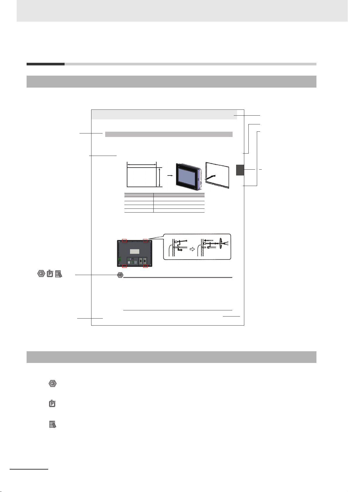
2-1-2 Installation onto the Operation Panel
Install the NB Unit by embedding it into the operation panel.
Use the metal kit and tool (a crosshead screwdriver) supplied with the Unit for installation.
Proceed the installation following the procedures below.
1
Panel cutout with dimensions is shown below. Fit the NB Unit into the panel from the front side.
2
As follows, insert panel fixators at the locations indicated by red box around the back of the NB Unit.
Insert the hooks of positioners into the square holes on the Unit to hold the fixators properly, and
tighten the screws firmly with the screwdriver.
NB5Q/NB7W-TWB
Precautions for Safe Use
• When operating on the operation panel, make sure to keep metal particles from entering the
Unit.
The mounting panel must be between 1.6 and 4.8 mm thick. The NB Unit must be installed
in a control panel.
For the sake of waterproof and dustproof, all the fixators must be evenly tightened to a
torque of 0.5~0.6 Nm. If the tightening torque exceeds the specified value, or the tightening
is not even, deformation of the front panel may occur.
Make sure that the operation panel is clean, unbent, and strong enough for the installation
process.
2-1-2 Installation onto the Operation Panel
Models Opening Dimension (W H mm)
NB3Q-TW00B/TW01B 119.0(+0.5/-0) 93.0(+0.5/-0)
NB5Q-TW00B/TW01B 172.4(+0.5/-0) 131.0(+0.5/-0)
NB7W-TW00B/TW01B 191.0(+0.5/-0) 137.0(+0.5/-0)
NB10W-TW01B 258.0(+0.5/-0) 200.0(+0.5/-0)
Opening dimensions
Width
Height
Level 1 heading
Level 2 heading
Level 3 heading
Step in a procedure
Manual name
Special Information
(See below.)
Level 3 heading
Page tab
Gives the current
headings.
Indicates a step in a
procedure.
Gives the number
of the section.
This illustration is provided only as a sample and may not literally appear in this manual.
Icons are used to indicate
precautions and
additional information.
Precautions for Safe Use
Precautions on what to do and what not to do to ensure using the product safely.
Precautions for Correct Use
Precautions on what to do and what not to do to ensure proper operation and performance.
Additional Information
Additional information to increase understanding or make operation easier.
Manual Structure
Page Structure and Icons
The following page structure and icons are used in this manual.
Special Information
Special information in this manual is classified as follows:
4
NB-series Programmable Terminals Host Connection Manual (V108)
Page 9

Terminology
The following terminology is used in this manual.
Terms Descriptions
NB Unit Indicates the main Unit of the products in the OMRON NB Series of Programmable
NB Series Indicates products in the OMRON NB Series of Programmable Terminal.
PLC Indicates a Programmable Controller.
CP Series Indicates the following products in the OMRON CP Series of Programmable
CS/CJ Series Indicates the following products in the OMRON CS/CJ Series of Programmable
NJ/NX Series Indicates the following OMRON SYSMAC NJ Series of Programmable Controllers:
C Series Indicates the following products in the OMRON C Series of Programmable Controllers:
Serial Communication
Unit
Serial Communication
Board
Communication Board Indicates a Communication Board for an OMRON C200HX/HG/HE(-Z) PLC.
CPU Unit Indicates a CPU Unit in the OMRON CP, CS/CJ or SYSMAC C Series of
NB-Designer Indicates the OMRON NB-Designer.
Host Indicates the PLC and other units functioning as the control devices for NB-Series
PT Indicates an OMRON Programmable Terminal.
Terminology
Terminal.
In this manual, unless otherwise specified, NB Series is taken as the subject
concerned.
Controllers: CP1H, CP1L, CP1E
Controllers: CS1G, CS1H, CS1G-H, CS1H-H, CJ1G, CJ1M, CJ2M, CJ2H
NJ501, NJ301, NX1P2
C200HX(-Z), C200HG(-Z), C200HE(-Z), CQM1, CQM1H, CPM1A, CPM2A, CPM2C
Indicates a Serial Communication Unit for an OMRON SYSMAC CS/CJ-Series PLC.
Indicates a Serial Communication Board for an OMRON SYSMAC CS/CJ-Series PLC.
Programmable Controllers.
Units.
NB-series Programmable Terminals Host Connection Manual (V108)
5
Page 10

Terminology
6
NB-series Programmable Terminals Host Connection Manual (V108)
Page 11

CONTENTS
Introduction............................................................................................................... 1
NB-series Manuals.................................................................................................... 2
Manual Structure ...................................................................................................... 4
Terminology .............................................................................................................. 5
Terms and Conditions Agreement ........................................................................ 11
Safety Precautions ................................................................................................. 13
Precautions for Safe Use ....................................................................................... 16
Precautions for Correct Use .................................................................................. 18
Conformance to EC Directives .............................................................................. 19
CONTENTS
Related Manuals ..................................................................................................... 20
Sec. 1 List for All PLCs Supported by NB Series........................... 1-1
1-1 Lists for Supported PLC ......................................................................................................... 1-2
1-2 Definition and Description of Serial Port COM ..................................................................... 1-7
Sec. 2 Connecting to SIEMENS PLCs ............................................. 2-1
2-1 Serial Port and Ethernet.......................................................................................................... 2-2
2-1-1 Serial Port................................................................................................................................... 2-2
2-1-2 Ethernet ...................................................................................................................................... 2-2
2-2 Communication Parameters and Cable Fabrication ............................................................ 2-3
2-2-1 Serial Port................................................................................................................................... 2-3
2-2-2 Ethernet ...................................................................................................................................... 2-3
2-3 Communication Parameter Setting........................................................................................ 2-4
2-3-1 When Using SIEMENS S7-200 Communication Protocol .......................................................... 2-4
2-3-2 When Using SIEMENS S7-300/400 (PC Adapter Direct) Communication Protocol ................... 2-5
2-3-3 SIEMENS S7-200 (SMART) Ethernet (TCP Slave).................................................................... 2-8
2-3-4 SIEMENS S7-300 Ethernet (TCP Slave).................................................................................. 2-17
2-3-5 SIEMENS S7-1200 Ethernet (TCP Slave)................................................................................ 2-23
2-4 Supported Registers ............................................................................................................. 2-27
2-4-1 SIEMENS S7-200..................................................................................................................... 2-27
2-4-2 SIEMENS S7-300/400 (PC Adapter Direct).............................................................................. 2-28
2-4-3 SIEMENS S7-200 (Smart) Ethernet (TCP Slave)..................................................................... 2-28
2-4-4 SIEMENS S7-300 Ethernet (TCP Slave).................................................................................. 2-29
2-4-5 SIEMENS S7-1200 Ethernet (TCP Slave)................................................................................ 2-30
2-5 Cable Fabrication .................................................................................................................. 2-31
NB-series Programmable Terminals Host Connection Manual (V108)
7
Page 12

CONTENTS
Sec. 3 Connecting to Mitsubishi PLCs............................................ 3-1
3-1 Serial Port and Ethernet.......................................................................................................... 3-2
3-1-1 Serial Port ...................................................................................................................................3-2
3-1-2 Ethernet.......................................................................................................................................3-3
3-2 Communication Setting and Cable Connection ................................................................... 3-5
3-2-1 Serial Port ...................................................................................................................................3-5
3-2-2 Ethernet.......................................................................................................................................3-6
3-3 Communication Setting .......................................................................................................... 3-7
3-3-1 When Using Mitsubishi FX1S, Mitsubishi FX1N/2N/3G and Mitsubishi FX3U Communication
Protocols .....................................................................................................................................3-7
3-3-2 When Using Mitsubishi FX-485ADP/485BD/232BD (Multi-station) Communication Protocols... 3-9
3-3-3 When Using FX2N-10GM/20GM Communication Protocol ...................................................... 3-12
3-3-4 When Using Mitsubishi Q00J (CPU Port) Communication Protocol .........................................3-13
3-3-5 When Using Mitsubishi Q series (CPU Port) Communication Protocol ....................................3-13
3-3-6 When Using Mitsubishi Q06H Communication Protocol ...........................................................3-14
3-3-7 When Using Mitsubishi Q_QnA (Link Port) Communication Protocol....................................... 3-15
3-3-8 When Using Mitsubishi FX Series Ethernet(TCP Slave) Communication Protocol ..................3-20
3-3-9 When Using Mitsubishi QnA 3EBin Ethernet (TCP Slave) Communication Protocol ...............3-23
3-3-10 When Using Mitsubishi QJ71E71 EtherNet Slave Communication Protocol ............................3-26
3-4 Supported Registers ............................................................................................................. 3-29
3-5 Cable Fabrication .................................................................................................................. 3-35
Sec. 4 Connecting to Schneider PLCs ............................................ 4-1
4-1 Serial Port Communication ....................................................................................................4-2
4-2 Communication Parameters and Cable Fabrication ............................................................ 4-3
4-3 Communication Parameter Setting........................................................................................ 4-4
4-4 Supported Registers ............................................................................................................. 4-13
4-5 Cable Fabrication .................................................................................................................. 4-14
Sec. 5 Modbus Connection .............................................................. 5-1
5-1 Serial Port and Ethernet.......................................................................................................... 5-2
5-2 Communication Parameters and Cable Fabrication ............................................................ 5-3
5-3 Communication Parameter Setting........................................................................................ 5-4
5-4 Supported Registers ............................................................................................................... 5-7
5-5 Cable Fabrication .................................................................................................................... 5-9
5-6 Modbus Protocol .................................................................................................................. 5-10
5-6-1 Introduction to Modbus Protocol ...............................................................................................5-10
5-6-2 When NB adopts Modbus TCP protocol (Master/Slave mode).................................................5-11
5-7 Example of NB as Modbus Slave ......................................................................................... 5-12
5-8 Example of connection using Modbus TCP protocol ........................................................ 5-15
5-9 Example of E5CC/E5EC, 3G3MX2 connection using Modbus RTU Extend Protocol ..... 5-16
5-10 Example of Power PMAC Motion Controller using Modbus TCP Slave Protocol............ 5-18
8
NB-series Programmable Terminals Host Connection Manual (V108)
Page 13

CONTENTS
Sec. 6 Connecting to Delta PLCs..................................................... 6-1
6-1 Serial Port Communication ....................................................................................................6-2
6-2 Communication Parameters and Cable Fabrication ............................................................ 6-3
6-3 Communication Parameter Setting........................................................................................ 6-4
6-4 Supported Registers ............................................................................................................... 6-6
6-5 Cable Fabrication .................................................................................................................... 6-7
Sec. 7 Connecting to LSIS PLCs...................................................... 7-1
7-1 Serial Port Communication ....................................................................................................7-2
7-2 Communication Parameters and Cable Fabrication ............................................................ 7-3
7-3 Communication Parameter Setting........................................................................................ 7-4
7-4 Supported Registers ............................................................................................................. 7-12
7-5 Cable Fabrication .................................................................................................................. 7-15
Sec. 8 Connecting to Panasonic Industrial Devices
SUNX PLCs............................................................................. 8-1
8-1 Serial Port Communication ....................................................................................................8-2
8-2 Communication Parameters and Cable Fabrication ............................................................ 8-3
8-3 Communication Parameter Setting........................................................................................ 8-4
8-4 Supported Registers ............................................................................................................... 8-5
8-5 Cable Fabrication .................................................................................................................... 8-6
Sec. 9 Connecting to Allen-Bradley (Rockwell) PLC ..................... 9-1
9-1 Serial Port Communication and Ethernet ............................................................................. 9-2
9-1-1 Serial Port................................................................................................................................... 9-2
9-1-2 Ethernet ...................................................................................................................................... 9-3
9-2 Communication Parameters and Cable Fabrication ............................................................ 9-4
9-2-1 Serial Port................................................................................................................................... 9-4
9-2-2 Ethernet ...................................................................................................................................... 9-4
9-3 Communication Parameter Setting........................................................................................ 9-5
9-3-1 When Using AB SLC500/MicroLogix Series (DF1) Protocol ...................................................... 9-5
9-3-2 When Using AB CompactLogix/ControlLogix Series (DF1) Protocol.......................................... 9-7
9-3-3 AB MicroLogix Series Ethernet(TCP Slave) ............................................................................. 9-11
9-4 Supported Registers ............................................................................................................. 9-14
9-5 Cable Fabrication .................................................................................................................. 9-16
Sec. 10 Connecting to PLC of GE Fanuc Automation Inc. ............ 10-1
10-1 Serial Port Communication .................................................................................................. 10-2
10-2 Serial Port Communication Parameters and Cable Fabrication ....................................... 10-3
10-3 Serial Port Communication Parameter Setting................................................................... 10-4
10-4 Supported Registers ............................................................................................................. 10-7
10-5 Cable Fabrication .................................................................................................................. 10-8
NB-series Programmable Terminals Host Connection Manual (V108)
9
Page 14

CONTENTS
Sec. 11 Connecting to Keyence PLCs............................................. 11-1
11-1 Serial Port and the Ethernet ................................................................................................. 11-2
11-2 Communication Setting and Cable Connection ................................................................. 11-3
11-3 Communication Setting ........................................................................................................ 11-4
11-3-1 When Using Keyence KV-3000 Communication Protocol ........................................................11-4
11-3-2 When Using Keyence KV-5000 EtherNetSlave Communication Protocol ................................11-5
11-4 Supported Registers ............................................................................................................. 11-7
11-5 Cable Connection .................................................................................................................. 11-8
Sec. 12 Connecting to OMRON Safety Controller .......................... 12-1
12-1 Serial Port............................................................................................................................... 12-2
12-2 Communication Parameters and Cable Fabrication .......................................................... 12-3
12-3 Communication Parameter Setting...................................................................................... 12-4
12-3-1 When using OMRON G9SP Communication Protocol..............................................................12-4
12-4 Supported Registers ............................................................................................................. 12-6
12-5 Cable Connection .................................................................................................................. 12-7
Revision History........................................................................................................1
10
NB-series Programmable Terminals Host Connection Manual (V108)
Page 15

Terms and Conditions Agreement
Terms and Conditions Agreement
Warranty, Limitations of Liability
Warranties
Exclusive Warranty
Omron’s exclusive warranty is that the Products will be free from defects in materials and workmanship for a period of twelve months from the date of sale by Omron (or such other period expressed in
writing by Omron). Omron disclaims all other warranties, express or implied.
Limitations
OMRON MAKES NO WARRANTY OR REPRESENTATION, EXPRESS OR IMPLIED, ABOUT
NON-INFRINGEMENT, MERCHANTABILITY OR FITNESS FOR A PARTICULAR PURPOSE OF
THE PRODUCTS. BUYER ACKNOWLEDGES THAT IT ALONE HAS DETERMINED THAT THE
PRODUCTS WILL SUITABLY MEET THE REQUIREMENTS OF THEIR INTENDED USE.
Omron further disclaims all warranties and responsibility of any type for claims or expenses based
on infringement by the Products or otherwise of any intellectual property right.
Buyer Remedy
Omron’s sole obligation hereunder shall be, at Omron’s election, to (i) replace (in the form originally
shipped with Buyer responsible for labor charges for removal or replacement thereof) the non-complying Product, (ii) repair the non-complying Product, or (iii) repay or credit Buyer an amount equal
to the purchase price of the non-complying Product; provided that in no event shall Omron be
responsible for warranty, repair, indemnity or any other claims or expenses regarding the Products
unless Omron’s analysis confirms that the Products were properly handled, stored, installed and
maintained and not subject to contamination, abuse, misuse or inappropriate modification. Return of
any Products by Buyer must be approved in writing by Omron before shipment. Omron Companies
shall not be liable for the suitability or unsuitability or the results from the use of Products in combination with any electrical or electronic components, circuits, system assemblies or any other materials or substances or environments. Any advice, recommendations or information given orally or in
writing, are not to be construed as an amendment or addition to the above warranty.
See http://www.omron.com/global/ or contact your Omron representative for published information.
Limitation on Liability; Etc
OMRON COMPANIES SHALL NOT BE LIABLE FOR SPECIAL, INDIRECT, INCIDENTAL, OR
CONSEQUENTIAL DAMAGES, LOSS OF PROFITS OR PRODUCTION OR COMMERCIAL LOSS IN
ANY WAY CONNECTED WITH THE PRODUCTS, WHETHER SUCH CLAIM IS BASED IN
CONTRACT, WARRANTY, NEGLIGENCE OR STRICT LIABILITY.
Further, in no event shall liability of Omron Companies exceed the individual price of the Product on
which liability is asserted.
NB-series Programmable Terminals Host Connection Manual (V108)
11
Page 16

Terms and Conditions Agreement
Application Considerations
Suitability of Use
Omron Companies shall not be responsible for conformity with any standards, codes or regulations
which apply to the combination of the Product in the Buyer’s application or use of the Product. At
Buyer’s request, Omron will provide applicable third party certification documents identifying ratings
and limitations of use which apply to the Product. This information by itself is not sufficient for a
complete determination of the suitability of the Product in combination with the end product, machine,
system, or other application or use. Buyer shall be solely responsible for determining appropriateness
of the particular Product with respect to Buyer’s application, product or system. Buyer shall take
application responsibility in all cases.
NEVER USE THE PRODUCT FOR AN APPLICATION INVOLVING SERIOUS RISK TO LIFE OR
PROPERTY WITHOUT ENSURING THAT THE SYSTEM AS A WHOLE HAS BEEN DESIGNED TO
ADDRESS THE RISKS, AND THAT THE OMRON PRODUCT(S) IS PROPERLY RATED AND
INSTALLED FOR THE INTENDED USE WITHIN THE OVERALL EQUIPMENT OR SYSTEM.
Programmable Products
Omron Companies shall not be responsible for the user’s programming of a programmable Product, or
any consequence thereof.
Disclaimers
Performance Data
Data presented in Omron Company websites, catalogs and other materials is provided as a guide for
the user in determining suitability and does not constitute a warranty. It may represent the result of
Omron’s test conditions, and the user must correlate it to actual application requirements. Actual
performance is subject to the Omron’s Warranty and Limitations of Liability.
Change in Specifications
Product specifications and accessories may be changed at any time based on improvements and other
reasons. It is our practice to change part numbers when published ratings or features are changed, or
when significant construction changes are made. However, some specifications of the Product may be
changed without any notice. When in doubt, special part numbers may be assigned to fix or establish
key specifications for your application. Please consult with your Omron’s representative at any time to
confirm actual specifications of purchased Product.
12
Errors and Omissions
Information presented by Omron Companies has been checked and is believed to be accurate;
however, no responsibility is assumed for clerical, typographical or proofreading errors or omissions.
NB-series Programmable Terminals Host Connection Manual (V108)
Page 17
Safety Precautions
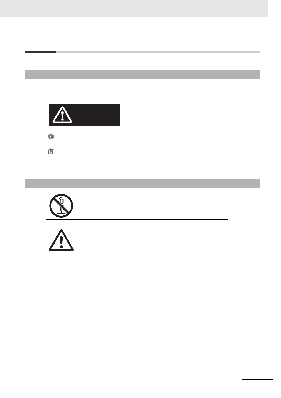
WARNING
Indicates an imminently hazardous situation which,
if not avoided, will result in death or serious injury.
Additionally, there may be severe property damage.
Precautions for Safe Use
Indicates precautions on what to do and what not to do to ensure using the product safely.
Precautions for Correct Use
Indicates precautions on what to do and what not to do to ensure proper operation
and performance.
Note Indicates suggestive information and precautions on operation of the product.
Notation Used for Safety Information
The following notation is used in this manual to provide precautions required to ensure safe usage of
the product. The safety precautions that are provided are extremely important to safety. Always read
and heed the information provided in all safety precautions.
Safety Precautions
Symbols
The circle and slash symbol indicates operations that you must not do.
The specific operation is shown in the circle and explained in text.
This example indicates prohibiting disassembly.
The triangle symbol indicates precautions (including warnings).
The specific operation is shown in the triangle and explained in text.
This example indicates a general precaution.
NB-series Programmable Terminals Host Connection Manual (V108)
13
Page 18
Safety Precautions
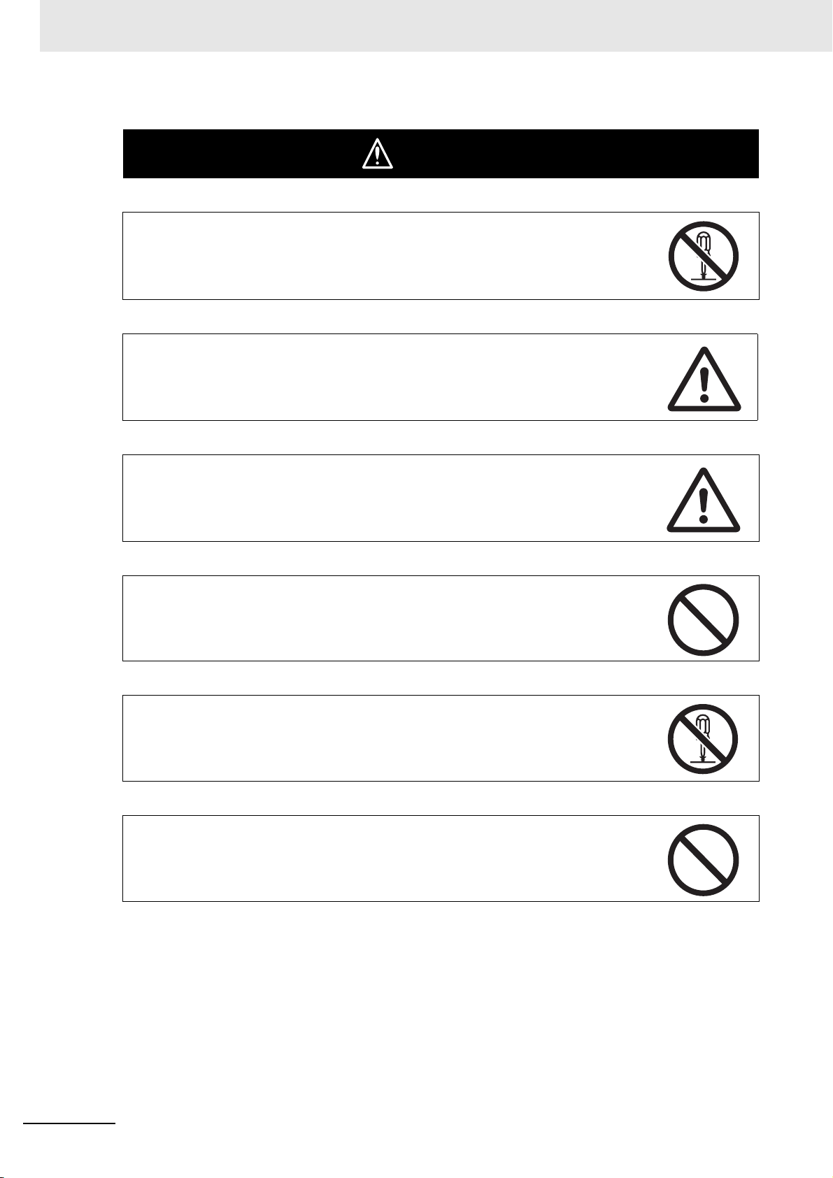
WARNING
Do not attempt to take the product apart and do not touch the product inside while the
power is being supplied. Otherwise it may result in electric shock.
Always ensure that the personnel in charge confirm that installation, inspection, and
maintenance were properly performed for the NB Unit.
“Personnel in charge” refers to individuals qualified and responsible for ensuring
safety during machine design, installation, operation, maintenance, and disposal.
Ensure that installation and post-installation checks are performed by personnel in
charge who possess a thorough understanding of the machinery to be installed.
Do not use the input functions of the touch switch, etc. of the NB Unit, in applications
that involve human life, in applications that may result in serious injury, or for
emergency stop switches.
Do not attempt to disassemble, repair, or modify the NB Unit. Otherwise it may impair
the safety functions.
Never press at two or more points on the touch panel of the NB Unit at a time.
Otherwise, it may activate a switch somewhere between the two points.
14
NB-series Programmable Terminals Host Connection Manual (V108)
Page 19
Precaution
Caution
NB
SG
SG
24V
0V
GND
Power
Supply
Grounding Grounding
Functional
Grounding
Cable
Contour Contour
PC
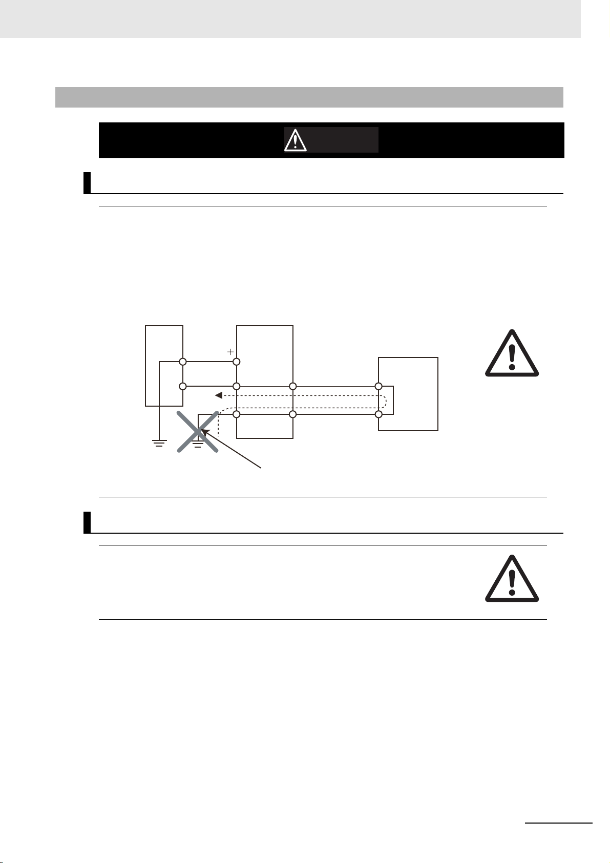
Do not ground the functional grounding.
Wiring
TIn the case of the NB Series, when grounding the positive terminal of power supply of 24
V to the NB, do not ground functional grounding terminal at NB side. Some functions of a
PC connected to the NB may cause a short circuit and the NB Unit may cause damage.
• Caution:
Depending on the types of PC, SG terminals of RS-232C port or USB port and contour of connector
can be connected. As the contour of tool port of the NB and the functional grounding terminal are not
insulated, they are connected. Therefore, connecting the PC allows GND terminal and functional
grounding terminal of the NB to be connected. If the power supply of 24V to the NB is grounded positively, grounding the functional grounding terminal allows a short circuit as shown in the diagram
below and may result in damage.
Safety Precautions
Test Function
The Test Function is performed on PC, and it has different behaviors with actual NB
running system. A problem may occur due to communication timing, cable differences and
unexpected PC circumstances (such as freeze). When the Test Function is performed,
please consider possible unexpected circumstances on the actual NB running system and
confirm that any dangerous event will not occur beforehand.
NB-series Programmable Terminals Host Connection Manual (V108)
15
Page 20

Precautions for Safe Use
Precautions for Safe Use
• When unpacking the NB Units and the peripheral devices, check carefully for any external scratches
or other damages. Also, shake the Units gently and check for any abnormal sound.
• The NB Unit must be installed in a control panel.
The mounting panel must be between 1.6 and 4.8 mm thick. Tighten the Mounting Brackets evenly to a
•
torque of between 0.5 and 0.6 N
exceeds the specified value, or the tightening is not even, deformation of the front panel may occur.
What is more, make sure the panel is not dirty or warped and that it is strong enough to hold the Units.
• Do not let metal particles enter the Units when preparing the panel.
• Do not connect an AC power supply to the DC power terminals.
• Use a DC power with a slight voltage fluctuation and reinforced or double insulation, and that will
provide a stable output even if the input is momentarily interrupted for 10 ms.
Rated Power Supply Voltage: DC 24 V (Allowable range DC 20.4 ~ 27.6 V)
• Do not perform a dielectric voltage test.
• Before connecting the power supply to the NB unit, mount the cable on the terminal block. Make the
connection by using terminal screws crimping on a twisted-pair cable with a crimping range of 12~26
AWG, and only 6.5 mm of insulation peel of the cable needs to be peeled off. Tighten the terminal
screws at a torque of between 0.3 and 0.5 N
use the terminal block of NB3Q-TWB for other models. NB3Q-TWB has different pin
definitions on the terminal block.
• To prevent malfunctions caused by noise, ground the Unit correctly.
• Do not touch the packaging part of the circuit board with your bare hands. Discharge any static
electricity from your body before handling the board.
• When using the No. 6 pin of the serial communication port COM1 connector for a voltage of DC+5V,
make sure the supply equipment’s current capacity is below 250mA before using it. The DC+5V
voltage output of the NB unit is +5V±5%, and the maximum current is 250mA. (The serial
communication port COM1 of NB3Q-TWB is unable to output the current.)
• Turn OFF the power supply before connecting or disconnecting cables.
• Always keep the connector screws firmly tightened after the communication cable is connected.
• The maximum tensile load for cables is 30 N. Do not apply loads greater than this.
Confirm the safety of the system before turning ON or OFF the power supply, or pressing the reset button.
•
• The whole system may stop depending on how the power supply is turned ON or OFF. Turn ON/OFF
the power supply according to the specified procedure.
Reset by pressing the reset button, or restart the power supply, once the DIP switch settings are changed.
•
• To ensure the system’s safety, make sure to incorporate a program that can confirm the normal
functionality of the NB Unit before running the system.
• Start actual system application only after sufficiently checking screen data, macros and the operation
of the program at the host side.
• Do not press the touch panel with a force greater than 30 N.
• Do not use hard or pointed objects to operate or scrub the screen, otherwise, the surface of the
screen may be damaged.
• Confirm the safety of the system before pressing the touch panel.
• Signals from the touch switches may not be input if the touch switches are pressed consecutively at
high speed. Confirm each input before proceeding to the next one.
• Do not accidentally press the touch panel when the backlight is not lit or when the display does not
appear. Make sure of the safety of the system before pressing the touch panel.
• To use numeric input functions safely, always make maximum and minimum limit settings.
• Before initializing screen data, confirm that existing data is backed up at the NB-Designer.
m to maintain water and dust resistance. If the tightening torque
m. Make sure the screws are properly tightened. Do not
16
NB-series Programmable Terminals Host Connection Manual (V108)
Page 21

Precautions for Safe Use
• When changing the password with the screen, do not reset or turn OFF the power supply until writing
is finished. Failure to save the password may cause the screen to fail to function.
When using an equipment monitor, confirm the safety of the system before carrying out the following operations:
•
• Changing monitor data.
• Changing operation mode.
• Forced set/reset.
• Changing the current value or the set value.
• Do not connect a USB connector to any device that is not applicable.
• When connecting the equipment with the USB HOST connector, make sure the supply equipment's
current capacity is below 150mA before using it. The DC+5V voltage output of the NB Unit is
+5V±5%, and the maximum current is 150mA.
• Before connecting a USB connector to a device, make sure that the device is free of damage.
• Commercially available and the recommended USB HUBs are different from the general
specifications of the NB Unit. The unit may not function well in an environment subject to noise, static
electricity. Therefore, when using a USB HUB, employ sufficient noise and static electricity insulation
measures, or install it at a site free of noise or static electricity.
• While uploading or downloading screen data or system programs, do not perform the following
operations that may corrupt the screen data or the system program:
• Turning OFF the power supply of the NB Unit.
• Pressing the PT’s reset switch.
• Dispose of the Units and batteries according to local ordinances as they apply.
Do not dispose the product into a fire. Doing so may cause the damage with the battery or electronic components.
•
• Do not apply an impact with the lithium cell, charge it, dispose it into a fire, or heat it. Doing either of
them may cause an ignition or a bursting.
• When exporting products with lithium primary batteries containing perchlorate at 6ppb or above to or
delivering them through California, USA, the following precautionary measures have to be publicized.
Perchlorate material - applicable through special processing. Refer to
http://www.dtsc.ca.gov/hazardouswaste/perchlorate.
NB-Series products contain lithium primary batteries. When exporting products containing this kind of
batteries to or delivering them through California, USA, label all the product packages as well as the
appropriate delivery packages.
Do not use benzene, paint thinner, or other volatile solvents, and do not use chemically treated cloths.
•
• Do not dispose the Units together with general waste at waste yards. When disposing them, follow
the related local ordinances or rules.
• Cannot replace the backlight lamp inside the NB Unit.
• Deterioration over time can cause the touch points to move. Calibrate the touch panel periodically.
• Water and oil resistance will be lost if the front sheet is torn or is peeling off. Do not use the Unit, if the
front sheet is torn or is peeling off.
• The rubber packing will deteriorate, shrink, or harden depending on the operating environment.
Inspect the rubber packing periodically.
• The communication cables of the COM1 and COM2 connectors are not interchangeable. Confirm the
pins of the ports before carrying out communications. (NB3Q-TWB only has COM1.)
Periodically check the installation conditions in applications where the PT is subject to contact with oil or water.
•
• Do not perform the following operations during the communication of the USB memory:
• Turning off the power supply of the NB Unit.
• Pressing the Reset button on the NB Unit.
• Removing the USB memory.
• Do not use the USB memory in the environment subject to strong vibration.
NB-series Programmable Terminals Host Connection Manual (V108)
17
Page 22

Precautions for Correct Use
Precautions for Correct Use
• Do not install the unit in any of the following locations:
Locations subject to severe changes in temperature
Locations subject to temperatures or humidity outside the range specified in the specifications
Locations subject to condensation as the result of high humidity
Locations subject to corrosive or flammable gases
Locations subject to strong shock or vibration
Locations outdoors subject to direct wind and rain
Locations subject to strong ultraviolet light
Locations subject to dust
Locations subject to direct sunlight
Locations subject to splashing oil or chemicals
• Take appropriate and sufficient countermeasures when installing systems in the following locations:
Locations subject to static electricity or other forms of noise
Locations subject to strong electric field or magnetic field
Locations close to power supply lines
Locations subject to possible exposure to radioactivity
• Precautions for software:
The update, restoration, uninstall and reinstallation of software in running status is prohibited in order
to guarantee the correct use of the product.
18
NB-series Programmable Terminals Host Connection Manual (V108)
Page 23

Conformance to EC Directives
Conformance to EC Directives
NB-Series Programmable Terminals are EMC compliant.
Concepts
OMRON products are electronic devices that are incorporated in machines and manufacturing
installations. OMRON PTs conform to the related EMC Directives (see note) so that the devices and
machines into which they are built can more easily conform to EMC Directives. The actual products
have been through inspections and are completely in accordance with EMC directives. However, when
they are built into customers’ systems, whether the systems also comply with these Directives is up to
the customers for further inspection.
EMC-related performance of OMRON PTs will vary depending on the configuration, wiring, and other
conditions of the OMRON equipment or control panel. The customer must, therefore, perform final
checks to confirm that the overall machine or device conforms to EMC standards.
Note The applicable EMC (Electromagnetic Compatibility) standards are as follows:
EMS (Electromagnetic sensitivity): EN61131-2: 2007
EMI (Electromagnetic Interference): EN61131-2: 2007
Conformance to EC Directives
NB-Series Programmable Terminals are EC compliant. Heed the following precautions in order to
ensure that the customer’s overall machine and device conform to EC Directives.
1
The PT must be installed in a control panel.
2
You must use reinforced insulation or double insulation for the DC power supply and the DC
power supply must have minimal voltage fluctuations and provide a stable output even if the
power supply input is interrupted for 10 ms.
3
The PTs conform to the standard EN 61131-2, but radiated emission characteristics (10m
regulations) may vary depending on the configuration of the control panel used, other devices
connected to the control panel, wiring, and other conditions. You must therefore confirm that the
overall machine or equipment complies with EC Directives.
4
This is a Class A product (Product for industry purpose). It may cause radio interference in
residential areas, in which case the user may be required to take adequate measures to reduce
interference.
Conformance to KC Standards
Observe the following precaution if you use NB-series Programmable Terminals in Korea.
Class A Device (Broadcasting Communications Device for Office Use)
This device obtained EMC registration for office use (Class A), and it is intended to be used in
places other than homes.
Sellers and/or users need to take note of this.
NB-series Programmable Terminals Host Connection Manual (V108)
19
Page 24

Related Manuals
Related Manuals
The related manuals are as follows:
Devices and Software Manual Name Manual No.
NB series NB Series NB-Designer Operation Manual V106
NB Series Setup Manual V107
NB Series Host Connection Manual (This manual) V108
NB Series Startup Guide V109
PLC SYSMAC CP Series CP1L CPU Unit Operation Manual W462
SYSMAC CP Series CP1H/L CPU Unit Programming Manual W451
SYSMAC CP Series CP1H CPU Unit Operation Manual W450
SYSMAC CP Series CP1E CPU Unit Hardware USER’S
Manual
SYSMAC CP Series CP1E CPU Unit Software USER’S
Manual
SYSMAC C200HX/HG/HE(-E/-ZE) Installation Guide W302
SYSMAC C200HX/HG/HE Operation Manual W303
SYSMAC C200HX/HG/HE(-ZE) Operation Manual W322
SYSMAC CPM1A Operation Manual W317
SYSMAC CPM2A Operation Manual W352
SYSMAC CPM1/CPM1A/CPM2A/CPM2C/SRM1(-V2)
Programming Manual
SYSMAC CPM2C Operation Manual W356
SYSMAC CS1 Series CS1G/H Operation Manual W339
SYSMAC CS/CJ Series Serial Communications Boards and
Serial Communications Units Operation Manual
SYSMAC CJ Series CJ1G/H(-H) CJ1M CJ1G Operation
Manual
SYSMAC CS/CJ Series Programming Manual W394
SYSMAC CS/CJ Series INSTRUCTIONS Reference Manual W340
SYSMAC CS/CJ Series Programming Consoles Operation
Manual
SYSMAC CS/CJ Series Communications Commands
Reference Manual
SYSMAC CJ Series CJ2 CPU Unit Hardware USER’S Manual W472
SYSMAC CJ Series CJ2 CPU Unit Software USER’S Manual W473
SYSMAC CS/CJ Series CS1W/CJ1W-ETN21 (100Base-TX)
Ethernet Units Operation Manual Construction of Networks
SYSMAC CS/CJ Series CS1W/CJ1W-ETN21 (100Base-TX)
Ethernet Units Operation Manual Construction of Applications
SYSMAC CS/CJ Series CS1W/CJ1W-EIP21 (100Base-TX)
EtherNet/IP
SYSMAC CP Series CP1L-EL/EM CPU Unit Operation Manual
NJ Series CPU Unit Hardware USER’S Manual
NJ/NX Series CPU Unit Software USER’S Manual
NJ/NX Series CPU Unit Built-in EtherNet/IPTM
Manual
NJ/NX Series Troubleshooting Manual
NX-Series NX1P2 CPU Unit Hardware User's Manual W578
NX-Series NX1P2 CPU Unit Built-in I/O and Option Board
User's Manual
TM
Units Operation Manual
Port USER’S
W479
W480
W353
W336
W393
W341
W342
W420
W421
W465
W516
W500
W501
W506
W503
W579
20
NB-series Programmable Terminals Host Connection Manual (V108)
Page 25

Related Manuals
Devices and Software Manual Name Manual No.
Safety Controller G9SP Series Safety Controller OPERATION MANUAL Z922
External Tool
CX-Programmer Ver.9.
Sysmac Studio Version 1 Operation Manual W504
Operation Manual
W446
NB-series Programmable Terminals Host Connection Manual (V108)
21
Page 26

Related Manuals
22
NB-series Programmable Terminals Host Connection Manual (V108)
Page 27

List for All PLCs Supported by NB
Series
This section lists all PLCs supported by NB Series.
1-1 Lists for Supported PLC . . . . . . . . . . . . . . . . . . . . . . . . . . . . . . . . . . . . . . . . 1-2
1-2 Definition and Description of Serial Port COM . . . . . . . . . . . . . . . . . . . . . . 1-7
1
NB-series Programmable Terminals Host Connection Manual (V108)
1-1
Page 28

1 List for All PLCs Supported by NB Series
1-1 Lists for Supported PLC
Names Displayed in NB-Designer PLC Models PLC Manufacturers
AB CompactLogix/ControlLogix
Series(DF1)
AB SLC500/MicroLogix Series(DF1) MicroLogix 1000
AB MicroLogix Series Ethernet (TCP
Slave)
Delta DVP DVP-xxES/EX/SS Delta
GE Fanuc Series SNP IC693CPU311/313 GE
GE SNP-X IC693CPU311/313/321/323
CompactLogix 1769-L20 Rockwell Automation,
CompactLogix 1769-L30
CompactLogix 1769-L31
CompactLogix 1769-L32E
CompactLogix 1769-L35E
ControlLogix 1756-L61
ControlLogix 1756-L63
MicroLogix 1200
MicroLogix 1400 1766-L32BWAA
MicroLogix 1500 1764-LRP
MicroLogix 1500 1764-LSP
SLC 5/03
SLC 5/04
SLC 5/05
MicroLogix 1100
MicroLogix 1400
1761-NET-ENI communication module
DVP-xxSA/SX/SC
DVP-xxEH/EH2/SV
IC693CPU321/323
IC693CPU331/340/341
IC693CPU350/351/352
IC693CPU360/363/364/374
IC693CSE311
IC693CSE313
IC693CSE323
IC693CSE331
IC693CSE340
IC693CPU331/340/341
IC693CPU350/351/352
IC693CPU360/363/364/374
CPU001/002/005
CPUE05
IC200UAL004/005/006
IC200UDD110/120/212
IC200UDR005/006/010
IC200UAA007
IC200UAR028
IC693CMM311
Inc.
1-2
NB-series Programmable Terminals Host Connection Manual (V108)
Page 29

1 List for All PLCs Supported by NB Series
Names Displayed in NB-Designer PLC Models PLC Manufacturers
LS Master-K Cnet K120s LSIS
K200s
LS Master-K CPU Direct K120s
K200s
LS Master-K Modbus RTU K120s
K200s
LS XGT CPU Direct XGT
XGB
LS XGT Cnet XBC-DN64H
XBC-DR32H
Mitsubishi FX Series Ethernet (TCP
Slave)
Mitsubishi FX1N/2N/3G FX1N
Mitsubishi FX1S FX1S
Mitsubishi FX2N-10GM/20GM FX2N_10GM
Mitsubishi FX3U FX3S
Mitsubishi FX-485ADP/485BD/232BD
(Multi-station)
Mitsubishi Q Series (CPU Port) Q02 CPU
Mitsubishi Q_QnA (Link Port) Q00 CPU
Mitsubishi Q00J (CPU Port) Q00J
Mitsubishi Q06H Q06H CPU
FX3U-ENET-L Mitsubishi
FX2N
FX3G
FX1NC
FX2NC
FX2N_20GM
FX3U
FX3UC
FX-485ADP/485BD/232BD
Q02H CPU
Q12H CPU
Q25H CPU
Q06UDHCPU
Q00UJ CPU
Q01 CPU
QJ71C24 module
QJ71C24-R2 module
QJ71C24N module
QJ71C24N-R2 module
QJ71C24N-R4 module
L02S CPU
LJ71C24 module
LJ71C24-R2 module
1-1 Lists for Supported PLC
1
NB-series Programmable Terminals Host Connection Manual (V108)
1-3
Page 30

1 List for All PLCs Supported by NB Series
Names Displayed in NB-Designer PLC Models PLC Manufacturers
Mitsubishi QnA 3Ebin Ethernet
(TCP Slave)
Mitsubishi QJ71E71 EtherNet Slave QJ71E71-100 module
Modbus ASCII Modbus Compatible External Device Modbus
Modbus RTU Modbus Compatible External Device
Modbus RTU Modicon_BE Modbus Compatible External Device
Modbus RTU Extend Modbus Compatible External Device
Modbus RTU Slave Modbus Compatible External Device
Modbus TCP Slave Modbus Compatible External Device
Q03UDE
Q04UDEH
Q06UDEH
Q10UDEH
Q13UDEH
Q20UDEH
Q26UDEH
Q50UDEH
Q100UDEH
Q03UDV
Q04UDV
Q06UDV
Q13UDV
Q26UDV
L02CPU
L02CPU-P
L06CPU
L06CPU-P
L26CPU
L26CPU-P
L26CPU-BT
L26CPU-PBT
LJ71E71-100 module
Mitsubishi
1-4
NB-series Programmable Terminals Host Connection Manual (V108)
Page 31

1 List for All PLCs Supported by NB Series
Names Displayed in NB-Designer PLC Models PLC Manufacturers
Omron C Series C200HX/HG/HE(-Z) Omron
CQM1H
CPM1/2
Omron CJ/CS Series CS1/CJ1/CJ2
Omron CP1H/L/E CP1H/L/E
Omron NX1 Series Host Link NX1P2-
Omron CJ/CS/NJ Series Ethernet (UDP
Slave)
Omron NX1 Series Ethernet (UDP Slave)
Omron CP Series Ethernet (UDP Slave) CP1L-EM
OMRON G9SP G9SP-N10S
Panasonic FP FP0/FP1/FP2/FP3 Panasonic Industrial
Schneider Modicon Uni-TelWay Micro Series Schneider
Schneider Twido Modbus RTU TWD LCAA 10DRF
CS1W-ETN21/EIP21
CJ1W-ETN21/EIP21
CJ2H--EIP
CJ2M-CPU3
NJ01
NX1P2-
CP1L-EL
CP1W-CIF41
CP1H
CP1L
G9SP-N10D
G9SP-N20S
FP2SH
FP10SH/FP10S
FP-M
FP-e
FP-X
Premium Series
Nano Series
TWD LCAA 16DRF
TWD LCAA 24DRF
TWD LMDA 20DTK
TWD LMDA 20DUK
TWD LMDA 20DRT
TWD LMDA 40DTK
TWD LMDA 40DUK
Devices SUNX
1-1 Lists for Supported PLC
1
NB-series Programmable Terminals Host Connection Manual (V108)
1-5
Page 32

1 List for All PLCs Supported by NB Series
Names Displayed in NB-Designer PLC Models PLC Manufacturers
Siemens S7-200 CPU212/214/215/216 Siemens
CPU221/222/224/226
CPU224 XP CN
CPU226 XP CN
SIEMENS S7-200 (Smart) Ethernet
(TCP Slave)
SIEMENS S7-300/400
(PC Adapter Direct)
SIEMENS S7-300 Ethernet
(TCP Slave)
SIEMENS S7-1200 Ethernet
(TCP Slave)
Keyence KV-3000 KV-3000 Keyence
Keyence KV-5000 EtherNet Slave KV-5000
CPU CR40
CPU SR20
CP 243-1communication module
CP 243-1 IT communication module
CPU312IFM/CPU313/CPU313C
CPU314IFM/CPU314
CPU315/CPU315-2 DP
CPU316/CPU316-2 DP
CPU318-2
CPU412-1/CPU412-2 DP
CPU413-1/CPU413-2 DP
CPU414-1/CPU414-2 DP/CPU414-3 DP
CPU416-1/CPU416-2 DP/CPU416-3 DP
CPU417-4
CPU315-2 PN/DP
CPU317-2 PN/DP
CPU319-3 PN/DP
CP 343-1 communication module
CP 343-1 IT communication module
CPU1211C
CPU1214C
1-6
NB-series Programmable Terminals Host Connection Manual (V108)
Page 33

1 List for All PLCs Supported by NB Series
Precautions for Safe Use
* Pin 4 and 5 are not used, thus not compliant with RS or CS function.
NB5Q/NB7W/NB10W-TWB
Pins COM1 Signals
1NC
2SD
3RD
4 RS(RTS)*
5 CS(CTS)*
6DC+5V
7NC
8NC
9SG
1-2 Definition and Description of
1-2 Definition and Description of Serial
Port COM
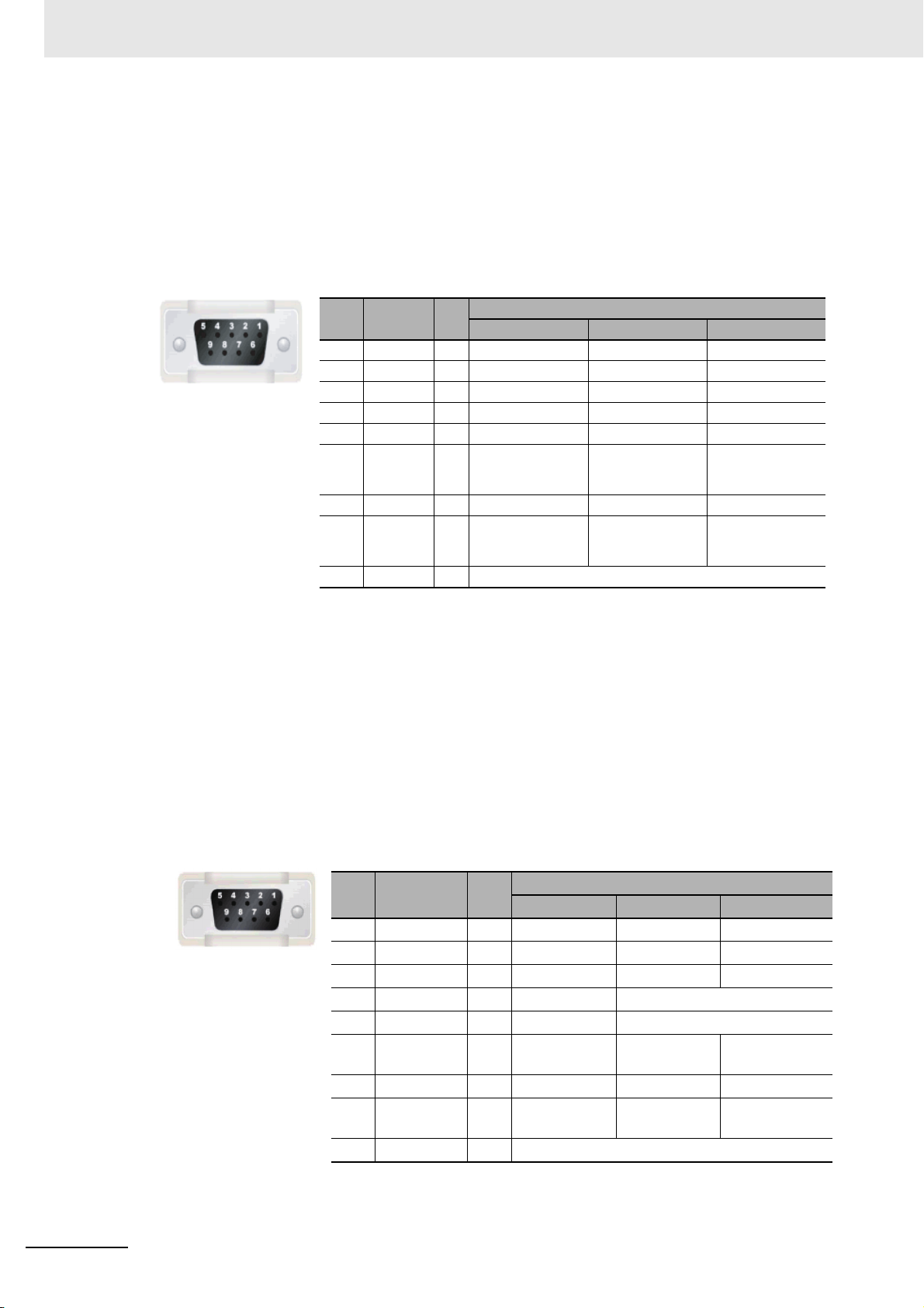
Serial Port COM1
• NB5Q/NB7W/NB10W-TWB
Serial port COM1 is a 9-pin D-type socket port. This port supports RS-232C communication
function, making it connectable to a controller which features RS-232C function, and it can also be
used for downloading programs or debugging for the product.
The pins are defined as follows:
Serial Port COM
1
When using the No. 6 pin of the serial communications port COM1 connector for a voltage of
DC+5V, make sure the supply equipment’s current capacity is below 250 mA before using it. The
DC+5V voltage output of the NB Unit is +5V±5%, and the maximum current is 250 mA.
NB-series Programmable Terminals Host Connection Manual (V108)
1-7
Page 34
1 List for All PLCs Supported by NB Series
* Pin 4 and 5 are not used, thus not compliant with RS or CS function.
Pins Signals I/O
Functions
RS-232C RS-485 RS-422A
1 SDB+ I/O - - Sending data(+)
2 SD O Sending data - -
3 RD I Receiving data - -
4 RS(RTS) O Request to send* - -
5 CS(CTS) I Clear to send* - -
6RDB+I/O - RS485B
Send/Receive
data(+)
Receiving
data(+)
7 SDA- I/O - - Sending data(-)
8RDA- I/O - RS485A
Send/Receive
data(-)
Receiving
data(-)
9 SG - Signal ground
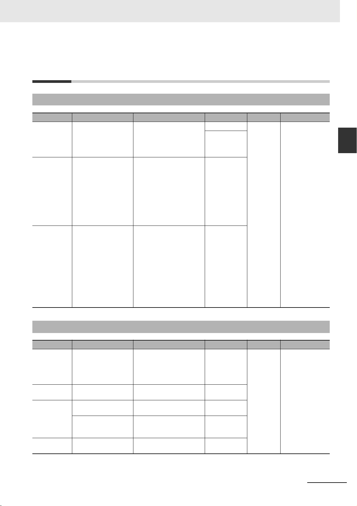
Pins Signals I/O
Functions
RS-232C RS-485 RS-422A
1 SDB+ I/O - - Sending data(+)
2 SD O Sending data - -
3 RD I Receiving data - -
4 Terminal R1 - - Terminal resistor
5 Terminal R2 - - Terminal resistor
6 RDB+ I/O - Send/Receive
data(+)
Receiving
data(+)
7 SDA- I/O - - Sending data(-)
8 RDA- I/O - Send/Receive
data(-)
Receiving
data(-)
9 SG - Signal ground
• NB3Q-TWB
NB3Q-TWB has only 1 serial port COM1, and this port supports communication (non-isolated)
based on RS-232C, RS-422 and RS-485, of which only 1 connection mode can be applied at one
time. By means of the RS-232C mode (PIN 2~5), it can be connected to a controller based on RS232C, and can also be used for downloading programs, as well as debugging for the product
(connected to a PC). While with the RS-422 or the RS-485 mode (PIN 1, PIN 6~8), only a PLC can
be connected.
The pins are defined as follows:
1-8
Precaution for Cable Fabrication
The COM 2 ports included in this manual and marked by cable manufacturers are intended for the
PT of NB5Q/NB7W/NB10W-TWB models, therefore when communication connection is carried
out with the COM 1 port of NB3Q-TWB, please refer to the pin definitions in this section prior to
connection.
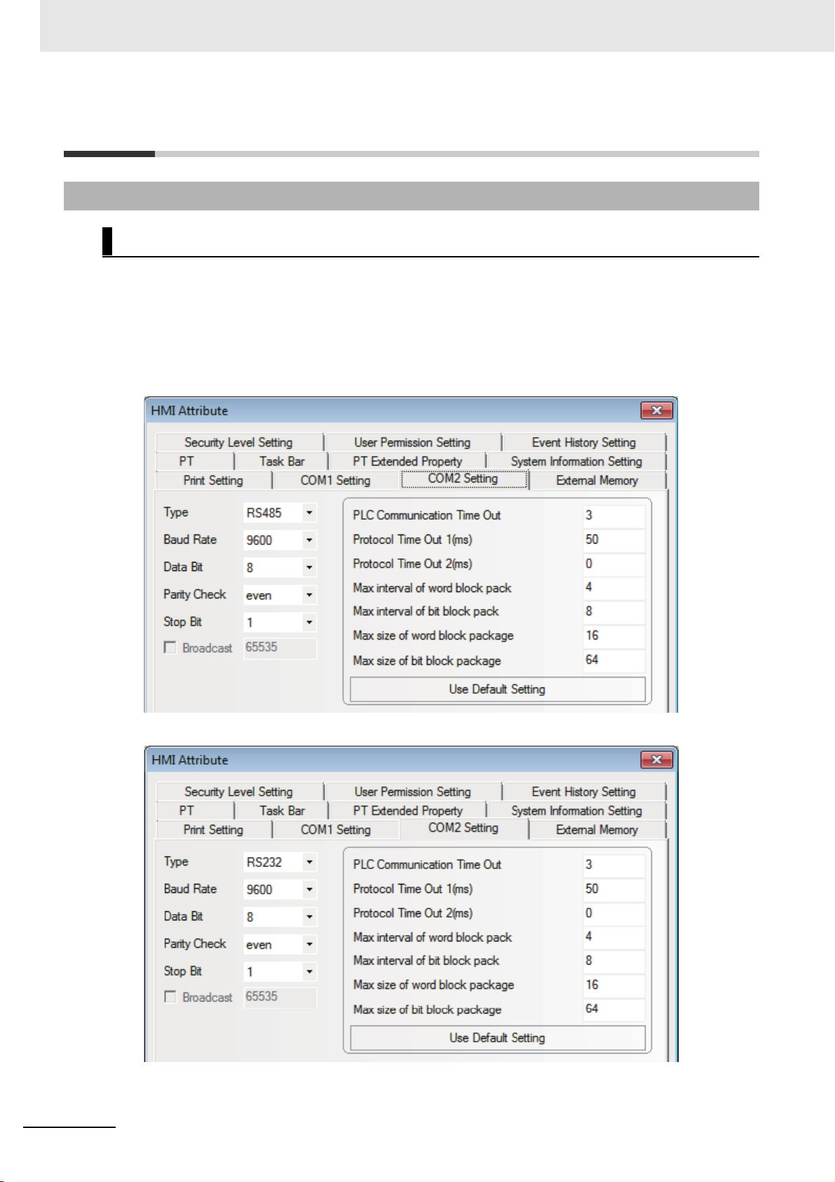
Serial Port COM2
• NB5Q/NB7W/NB10W-TWB
Serial port COM2 is a 9-pin D-type socket port. This port supports RS-232C/RS-485/RS-422A
communication function.
The pins are defined as follows:
NB-series Programmable Terminals Host Connection Manual (V108)
Page 35

Connecting to SIEMENS PLCs
This section describes the connection to SIEMENS PLCs.
2-1 Serial Port and Ethernet . . . . . . . . . . . . . . . . . . . . . . . . . . . . . . . . . . . . . . . . 2-2
2-1-1 Serial Port . . . . . . . . . . . . . . . . . . . . . . . . . . . . . . . . . . . . . . . . . . . . . . . . . . . . 2-2
2-1-2 Ethernet . . . . . . . . . . . . . . . . . . . . . . . . . . . . . . . . . . . . . . . . . . . . . . . . . . . . . . 2-2
2-2 Communication Parameters and Cable Fabrication . . . . . . . . . . . . . . . . . . 2-3
2-2-1 Serial Port . . . . . . . . . . . . . . . . . . . . . . . . . . . . . . . . . . . . . . . . . . . . . . . . . . . . 2-3
2-2-2 Ethernet . . . . . . . . . . . . . . . . . . . . . . . . . . . . . . . . . . . . . . . . . . . . . . . . . . . . . . 2-3
2-3 Communication Parameter Setting . . . . . . . . . . . . . . . . . . . . . . . . . . . . . . . 2-4
2-3-1 When Using SIEMENS S7-200 Communication Protocol . . . . . . . . . . . . . . . . 2-4
2-3-2 When Using SIEMENS S7-300/400 (PC Adapter Direct) Communication
Protocol . . . . . . . . . . . . . . . . . . . . . . . . . . . . . . . . . . . . . . . . . . . . . . . . . . . . . 2-5
2-3-3 SIEMENS S7-200 (SMART) Ethernet (TCP Slave) . . . . . . . . . . . . . . . . . . . . . 2-8
2-3-4 SIEMENS S7-300 Ethernet (TCP Slave) . . . . . . . . . . . . . . . . . . . . . . . . . . . . 2-17
2-3-5 SIEMENS S7-1200 Ethernet (TCP Slave) . . . . . . . . . . . . . . . . . . . . . . . . . . . 2-23
2-4 Supported Registers . . . . . . . . . . . . . . . . . . . . . . . . . . . . . . . . . . . . . . . . . . 2-27
2-4-1 SIEMENS S7-200 . . . . . . . . . . . . . . . . . . . . . . . . . . . . . . . . . . . . . . . . . . . . . 2-27
2-4-2 SIEMENS S7-300/400 (PC Adapter Direct) . . . . . . . . . . . . . . . . . . . . . . . . . . 2-28
2-4-3 SIEMENS S7-200 (Smart) Ethernet (TCP Slave) . . . . . . . . . . . . . . . . . . . . . 2-28
2-4-4 SIEMENS S7-300 Ethernet (TCP Slave) . . . . . . . . . . . . . . . . . . . . . . . . . . . . 2-29
2-4-5 SIEMENS S7-1200 Ethernet (TCP Slave) . . . . . . . . . . . . . . . . . . . . . . . . . . . 2-30
2-5 Cable Fabrication . . . . . . . . . . . . . . . . . . . . . . . . . . . . . . . . . . . . . . . . . . . . . 2-31
2
NB-series Programmable Terminals Host Connection Manual (V108)
2-1
Page 36

2 Connecting to SIEMENS PLCs
2-1 Serial Port and Ethernet
2-1-1 Serial Port
Series CPU Link Module Driver
S7-200
S7-300
S7-400
CPU212
CPU214
CPU215
CPU216
CPU221
CPU222
CPU224
CPU226
CPU224 XP CN
CPU226 XP CN
CPU312IFM
CPU313
CPU313C
CPU314
CPU314IFM
CPU315
CPU315-2 DP
CPU316
CPU316-2 DP
CPU318-2
CPU412-1
CPU412-2 DP
CPU413-1
CPU413-2 DP
CPU414-1
CPU414-2 DP
CPU414-3 DP
CPU416-1
CPU416-2 DP
CPU416-3 DP
CPU417-4
RS485 on the CPU unit SIEMENS S7-200
MPI port on the CPU unit SIEMENS S7-300/400 (PC Adapter Direct)
MPI port on the CPU unit
2-1-2 Ethernet
Series CPU Link Module Driver
2-2
S7-200
S7-200
SMART
S7-300
S7-1200
CPU222
CPU224
CPU226
CPU224 XP CN
CPU226 XP CN
CR40
SR20
CPU315-2DP CP 343-1
CPU315-2 PN/DP
CPU317-2 PN/DP
CPU319-3 PN/DP
CPU1211C
CPU1214C
CP 243-1
CP 243-1 IT
Ethernet interface on CPU
CP 343-1 IT
Ethernet interface on CPU
Ethernet interface on CPU
NB-series Programmable Terminals Host Connection Manual (V108)
SIEMENS
S7-200 (Smart) Ethernet (TCP Slave)
SIEMENS
S7-300 Ethernet (TCP Slave)
SIEMENS
S7-1200 Ethernet (TCP Slave)
Page 37
2 Connecting to SIEMENS PLCs
2-2 Communication Parameters and
Cable Fabrication
2-2 Communication Parameters and Cable
2-2-1 Serial Port
Series CPU Link Module COMM Type Parameter Cable
S7-200
S7-300
S7-400
CPU222
CPU224
CPU226
CPU224 XP CN
CPU226 XP CN
CPU312IFM
CPU313
CPU313C
CPU314
CPU314IFM
CPU315
CPU315-2 DP
CPU316
CPU316-2 DP
CPU318-2
CPU412-1
CPU412-2 DP
CPU412-3H
CPU413-1
CPU413-2 DP
CPU414-1
CPU414-2 DP
CPU414-3 DP
CPU416-1
CPU416-2 DP
CPU416-3 DP
CPU417-4
RS485 on the CPU unit RS232 Refer to
RS485
MPI port on the CPU unit RS232
S7-300/400
(PC Adapter
Direct) protocol
MPI port on the CPU unit RS232
S7-300/400
(PC Adapter
Direct) protocol
Section 2-3
Self-made cable
required
Fabrication
2
2-2-1 Serial Port
2-2-2 Ethernet
Series CPU Link Module COMM Type Parameter Cable
CPU222
CPU224
S7-200
S7-200
SMART
S7-300
S7-1200
NB-series Programmable Terminals Host Connection Manual (V108)
CPU226
CPU224 XP CN
CPU226 XP CN
CR40
SR20
CPU315-2DP CP 343-1
CPU315-2 PN/DP
CPU317-2 PN/DP
CPU319-3 PN/DP
CPU1211C
CPU1214C
CP 243-1
CP 243-1 IT
Ethernet Port of CPU Unit -
CP 343-1 IT
Ethernet Port of CPU Unit -
Ethernet Port of CPU Unit -
- Refer to
Section 2-3
-
Network Cable
2-3
Page 38
2 Connecting to SIEMENS PLCs
2-3 Communication Parameter Setting
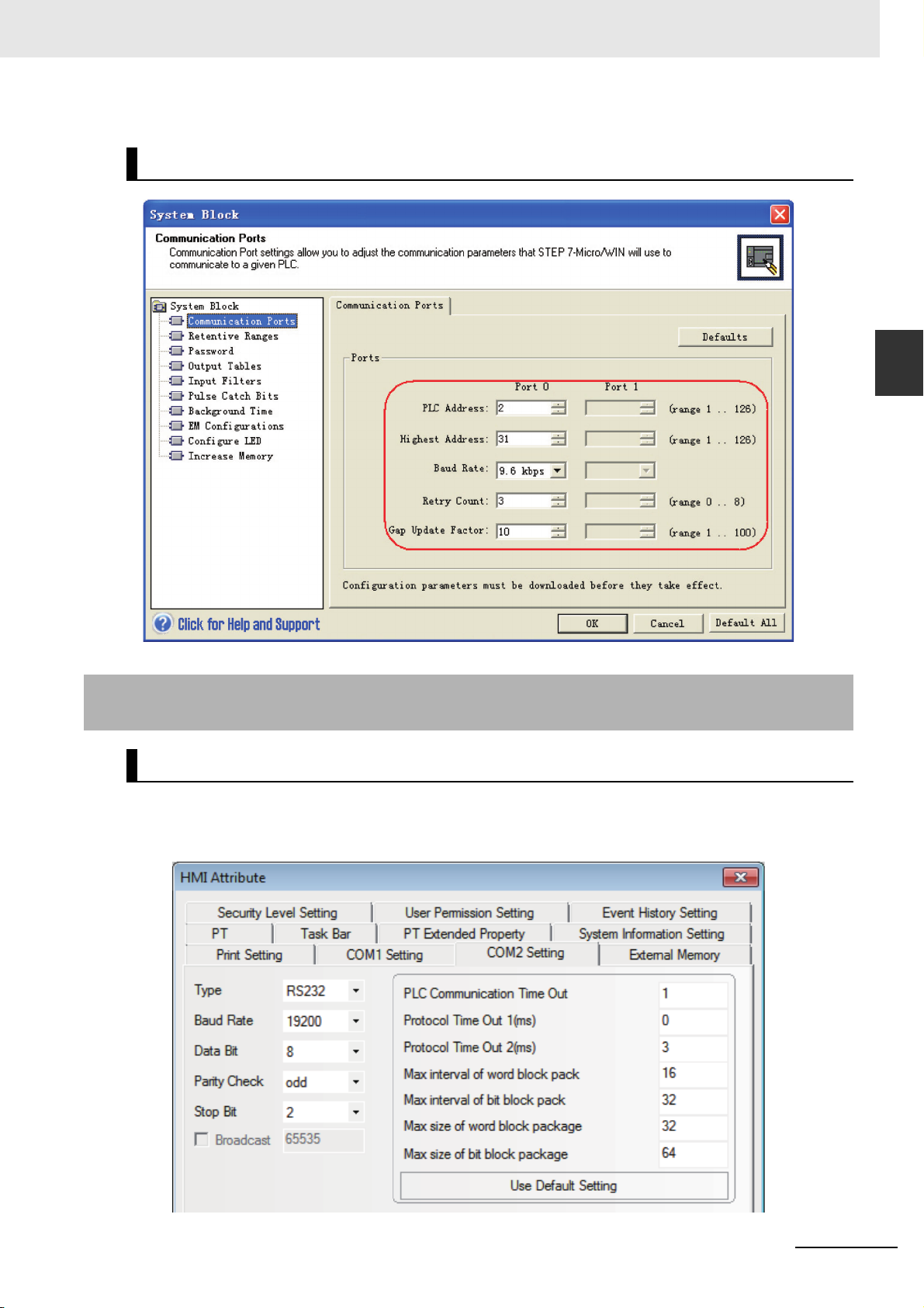
2-3-1 When Using SIEMENS S7-200 Communication Protocol
PT Settings
PT default communication parameters: 9600bps (Baud Rate), 8 (Data Bit), 1 (Stop Bit), even(Parity
Check) and 2 (PLC Station No.)
Note The maximum communication baud rate is 187.5K that is not supported by the direct online.
The PLC No. should match with the PLC No. in PT. Because the PLC address of S7-200 ranges from 1 to
126, so the PLC No. in PT should also range from 1 to 126.
RS485 Communication
RS232 Communication
2-4
NB-series Programmable Terminals Host Connection Manual (V108)
Page 39
PLC Settings
2 Connecting to SIEMENS PLCs
2-3 Communication Parameter Setting
2
2-3-2 When Using SIEMENS S7-300/400 (PC Adapter Direct) Communication Protocol
2-3-2 When Using SIEMENS S7-300/400 (PC Adapter Direct)
Communication Protocol
PT Settings
PT default communication parameters: 19200bps(Baud Rate), 8(Data Bit), 2(Stop Bit), odd (Parity
Check) and 2 (PLC Station No.) (Multiple Station No. is not supported.)
RS232 Communication
NB-series Programmable Terminals Host Connection Manual (V108)
2-5
Page 40
2 Connecting to SIEMENS PLCs
Note 1 The PLC Station No. is not needed if the PC adapter is used, which realize one for one communication.
2 When MPI-Adapter SSW7, RS232 (Order No.700-751-1VK21) manufactured by Helmholz is used, set the
communication speed as follows. Also the firmware of the MPI-Adapter should be V3.4b7 or later.
• PLC communication speed: 19.2/187.5 kbps
• PT communication speed: 9600/14400/19200/38400/56000/57600/115200 bps
3 DB blocks should be established in PLC program configuration, otherwise the relevant registers (DB.DBX,
DB.DBW, DB.DBD) can not be written. The even parity should be used on the initial addresses of
DBm.DBW and DBm.DBD.
Note For information of the product manufactured by Helmholz, please access to website as follows.
Systeme Helmholz GmbH
http://www.helmholz.de/
If the firmware version of the purchased MPI-Adapter is old, please download SHTools from website as
above to update the firmware.
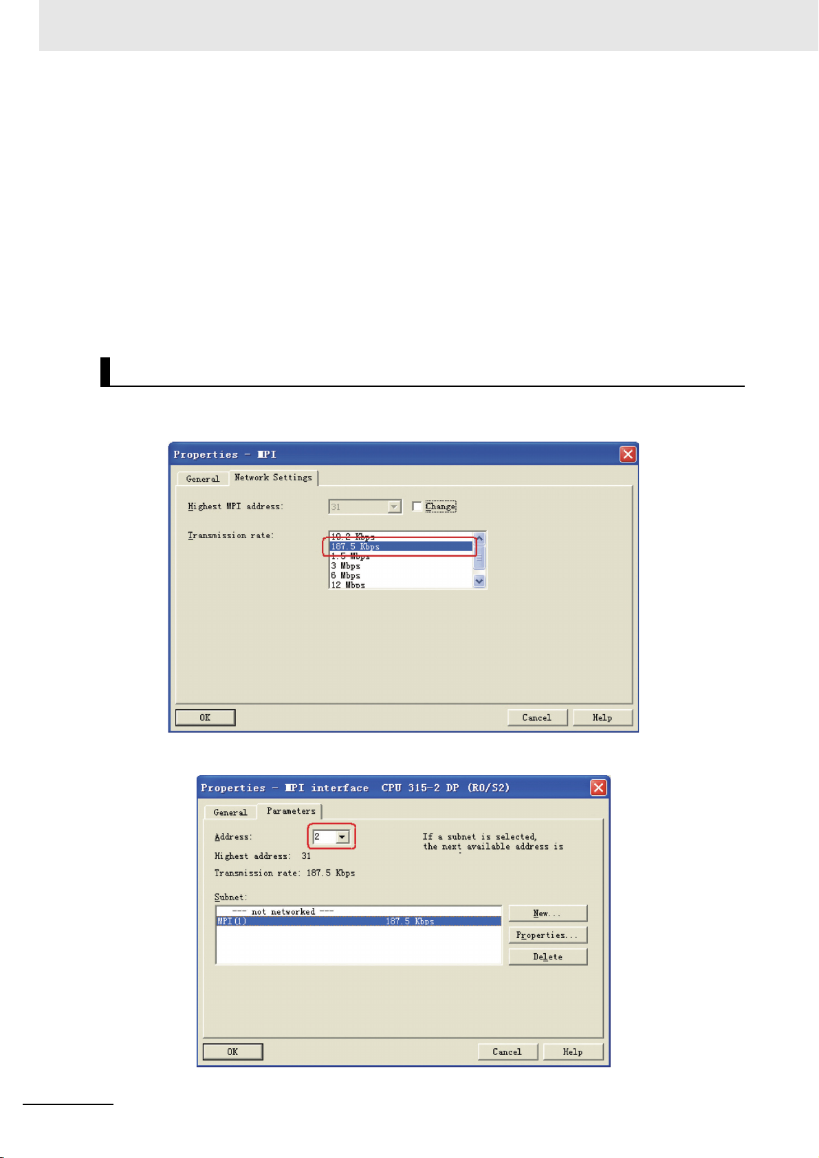
PLC Settings
1
When MPI-Adapter manufactured by Helmholz is used, set the communication speed of PLC to
19.2 Kbps or 187.5 Kbps.
2-6
2
The MPI address must be 2.
NB-series Programmable Terminals Host Connection Manual (V108)
Page 41
2 Connecting to SIEMENS PLCs
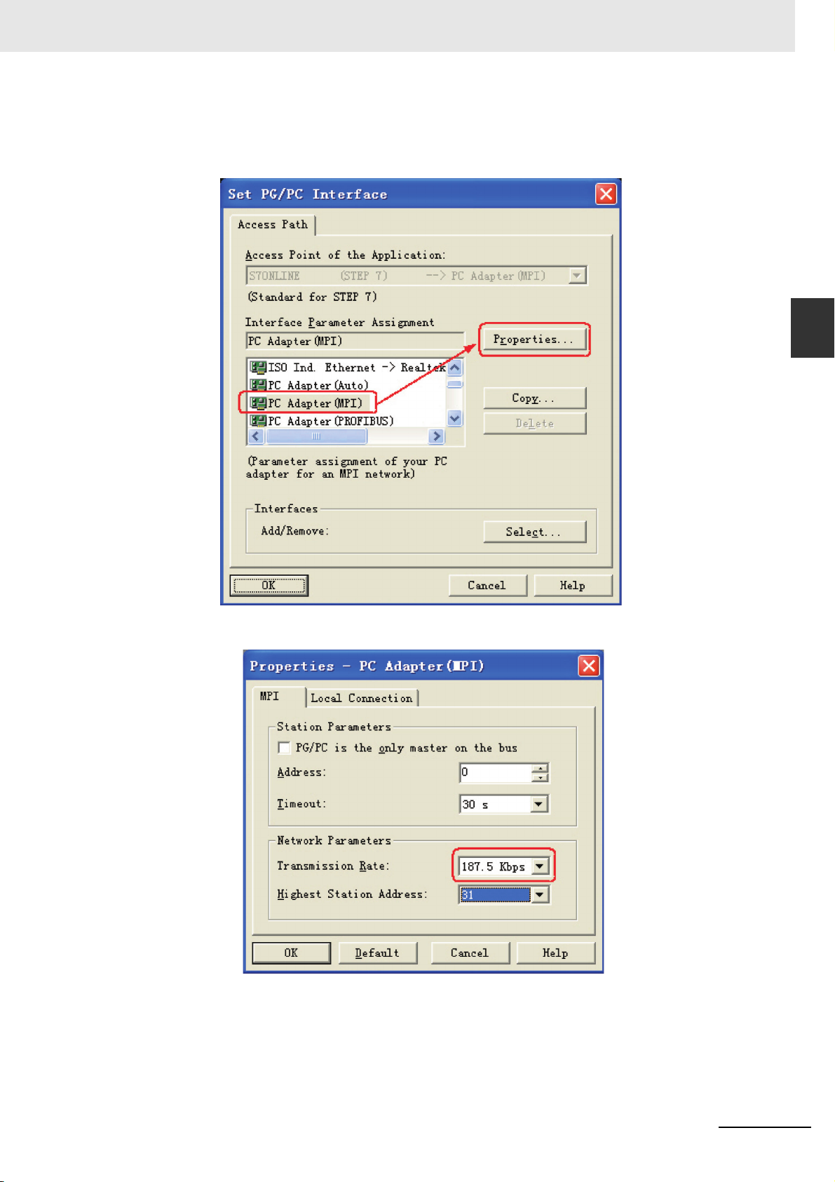
3
Download the set parameters to PLC after the setting is completed. Then open [SIMATIC
Manager] menu-[Option]-[PG/PC Interface Setting], select PC Adapter (MPI) and modify the
transmission rate of MPI port to be 187.5K, as shown below:
2-3 Communication Parameter Setting
2
2-3-2 When Using SIEMENS S7-300/400 (PC Adapter Direct) Communication Protocol
NB-series Programmable Terminals Host Connection Manual (V108)
2-7
Page 42

2 Connecting to SIEMENS PLCs
2-3-3 SIEMENS S7-200 (SMART) Ethernet (TCP Slave)
PT Settings
2-8
NB-series Programmable Terminals Host Connection Manual (V108)
Page 43

Note When you use S7-200 SMART, observe the following setting.
Set the [PLC property] - [Protocol Time Out 2] to "20".
2 Connecting to SIEMENS PLCs
2-3 Communication Parameter Setting
2
2-3-3 SIEMENS S7-200 (SMART) Ethernet (TCP Slave)
PLC Settings
Using Ethernet Port of CPU Unit
When you use the Unit that uses built-in Ethernet Port, set the Unit with STEP7-MICRO/WIN Smart.
1
Double-click the [Communications].
NB-series Programmable Terminals Host Connection Manual (V108)
2-9
Page 44

2 Connecting to SIEMENS PLCs
2
Connect the PLC to be connected on the Ethernet Network that is connectable with PC and
click the [Find CPUs].
3
Select the found CPU and click the [Edit] button.
2-10
NB-series Programmable Terminals Host Connection Manual (V108)
Page 45

4
Set IP address and others and click the [Set] button.
2 Connecting to SIEMENS PLCs
2-3 Communication Parameter Setting
2
2-3-3 SIEMENS S7-200 (SMART) Ethernet (TCP Slave)
Using communication module
When you use communication module, make settings with STEP7 Micro/Win.
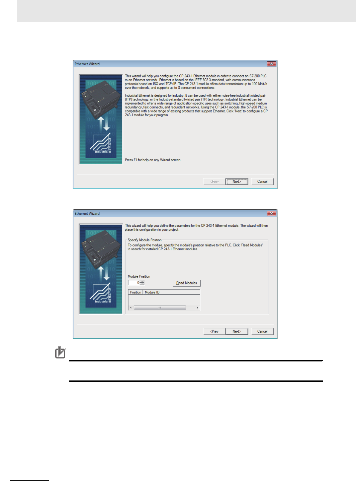
1
Select the [Tools] - [Ethernet Wizard...] from Menu.
NB-series Programmable Terminals Host Connection Manual (V108)
2-11
Page 46
2 Connecting to SIEMENS PLCs
Precautions for Correct Use
Precautions for Correct Use
2
Click the [Next>] button.
3
Set the Module Position to "0" and click the [Next>] button.
In order to communicate with the NB, the Module Position must be "0". If yours not the case,
change the CPU configurations and set the Module Position to "0".
2-12
NB-series Programmable Terminals Host Connection Manual (V108)
Page 47
2 Connecting to SIEMENS PLCs
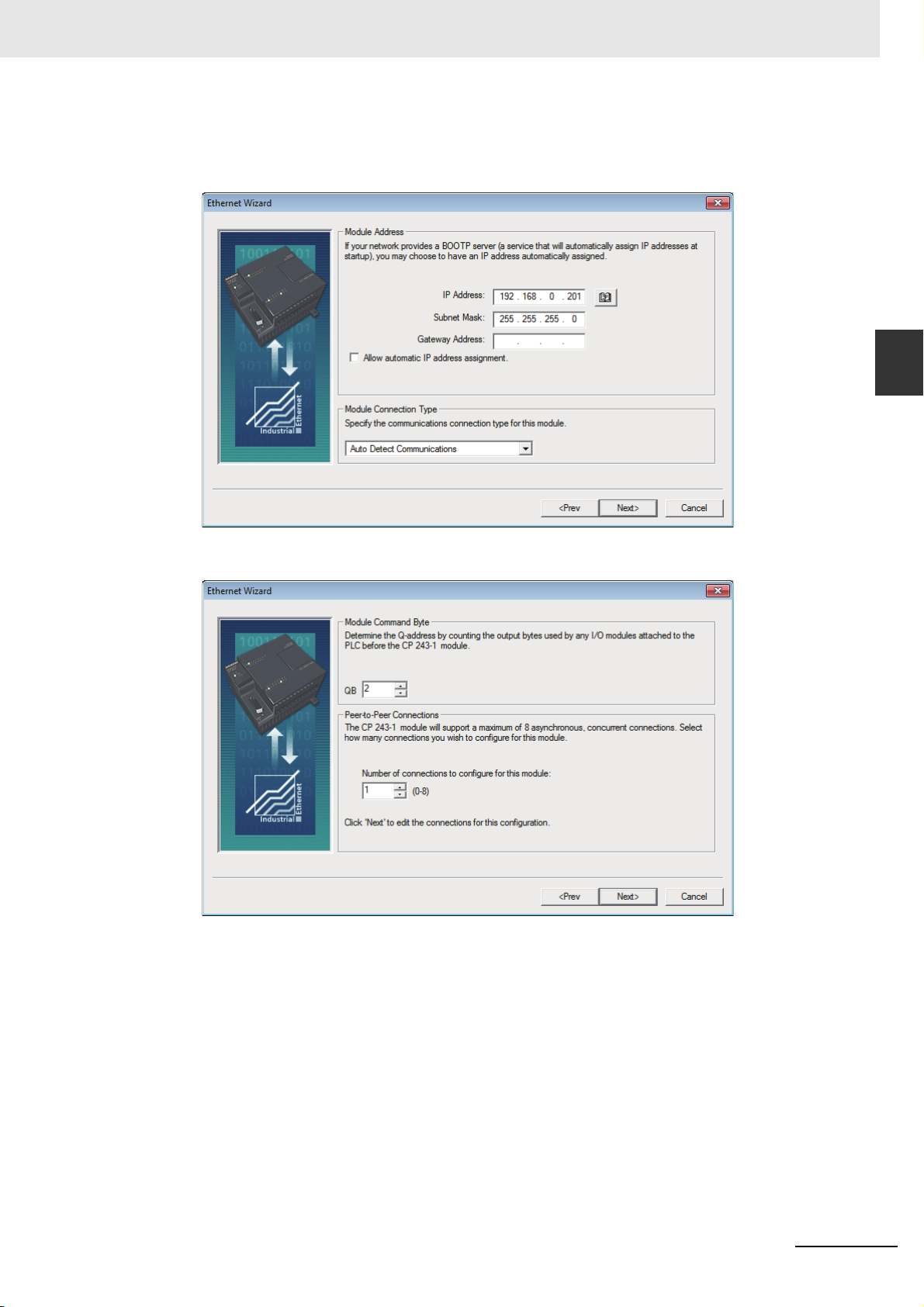
4
Make settings of IP address and others and select the [Auto Detect Communications] for the
[Module Connection Type].
When completing the settings, click the [Next>] button.
2-3 Communication Parameter Setting
2
2-3-3 SIEMENS S7-200 (SMART) Ethernet (TCP Slave)
5
Make settings as below and click the [Next>] button.
NB-series Programmable Terminals Host Connection Manual (V108)
2-13
Page 48

2 Connecting to SIEMENS PLCs
6
Make settings as below and click the [OK] button.
7
Make settings as below and click the [Next>] button.
2-14
NB-series Programmable Terminals Host Connection Manual (V108)
Page 49

8
Click the [Suggest Address] button and then the [Next>] button.
2 Connecting to SIEMENS PLCs
2-3 Communication Parameter Setting
2
2-3-3 SIEMENS S7-200 (SMART) Ethernet (TCP Slave)
9
Click the [Finish] button.
10
Click the [Yes] button.
NB-series Programmable Terminals Host Connection Manual (V108)
2-15
Page 50

2 Connecting to SIEMENS PLCs
11
Correct your program to call the subroutine ETH0_CTRL for each cycle.
2-16
NB-series Programmable Terminals Host Connection Manual (V108)
Page 51

2-3-4 SIEMENS S7-300 Ethernet (TCP Slave)
PT Settings
2 Connecting to SIEMENS PLCs
2-3 Communication Parameter Setting
2
2-3-4 SIEMENS S7-300 Ethernet (TCP Slave)
PLC Settings
Using Ethernet Port of CPU Unit
Make settings with SIMATIC STEP 7 (TIA Portal).
NB-series Programmable Terminals Host Connection Manual (V108)
2-17
Page 52
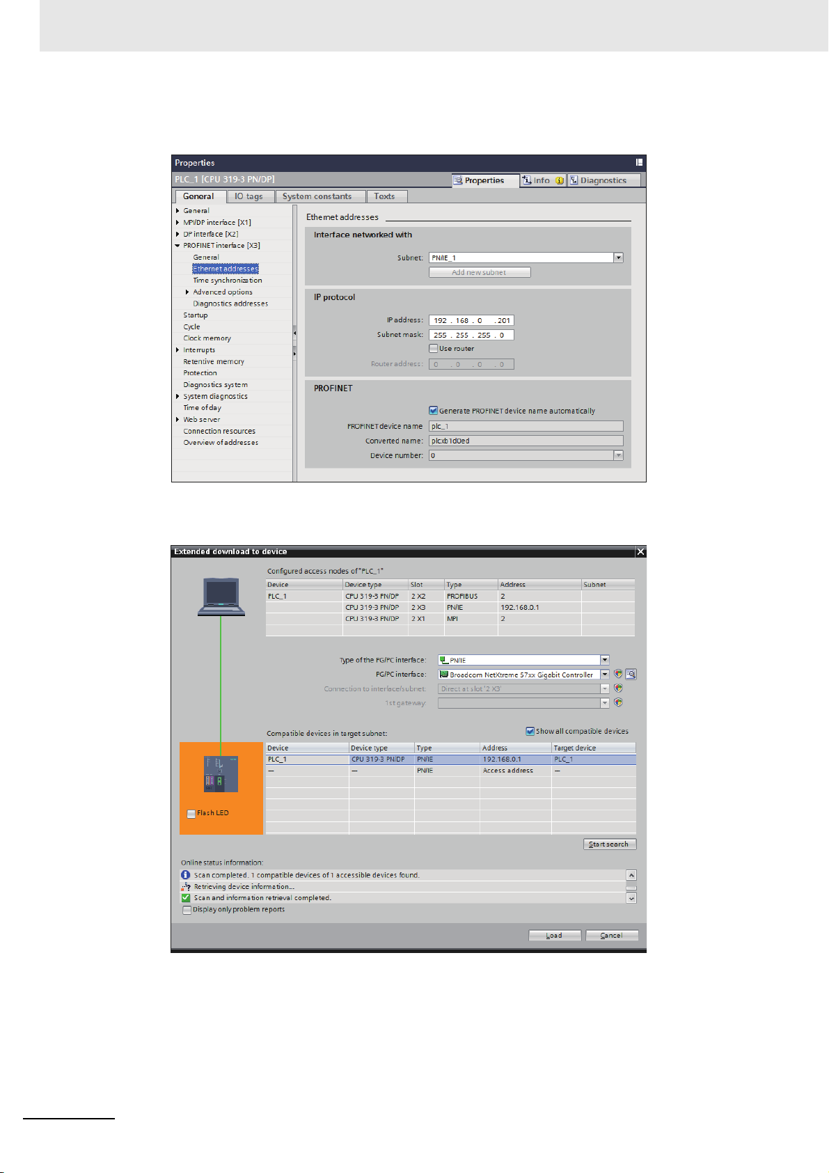
2 Connecting to SIEMENS PLCs
1
Double-click the [General] tab - [PROFINET interface [X3]] - [Ethernet addresses] and set IP
address and others.
2
Transfer the set descriptions to the PLC. If you transfer the descriptions for the first time, select
the [Extended download to device] and check in the [Show All compatible devices] check box.
2-18
NB-series Programmable Terminals Host Connection Manual (V108)
Page 53
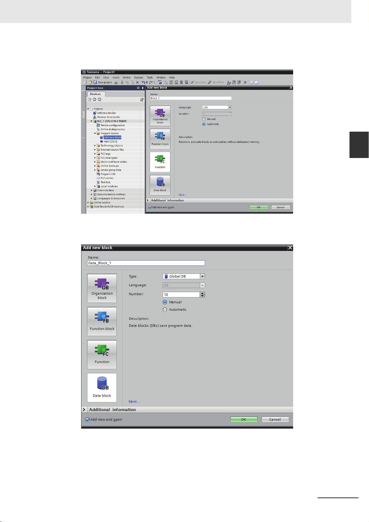
3
Create a Data block.
Double-click the [Project tree] - [Add new block].
2 Connecting to SIEMENS PLCs
2-3 Communication Parameter Setting
2
2-3-4 SIEMENS S7-300 Ethernet (TCP Slave)
4
Click the Data Block.
Example: If you create a new Data block DB10, make settings as below.
NB-series Programmable Terminals Host Connection Manual (V108)
2-19
Page 54

2 Connecting to SIEMENS PLCs
Additional Information
• If you use the Data block, the data type of the NB and the PLC should be the same. For
instance, if the Data type of the PLC is REAL, the storing data type of the numeric input component should be Float.
• When you define the Data block, secure the larger area than the one used for the NB. For
instance, in order to use DB5.DBW32 in the NB, you need to secure DB5.DBW34 or later for
the PLC.
• If you use the data block, do not check in the check box, [Properties] - [Attributes] - [Only store
in load memory].
Using communication module
Make settings with SIMATIC STEP 7 (TIA Portal).
1
Open the [Device overview] and click the [PLC].
2
Click the [General] tab - [MPI address]. Set the [Parameters] - [Address] to "2".
2-20
NB-series Programmable Terminals Host Connection Manual (V108)
Page 55
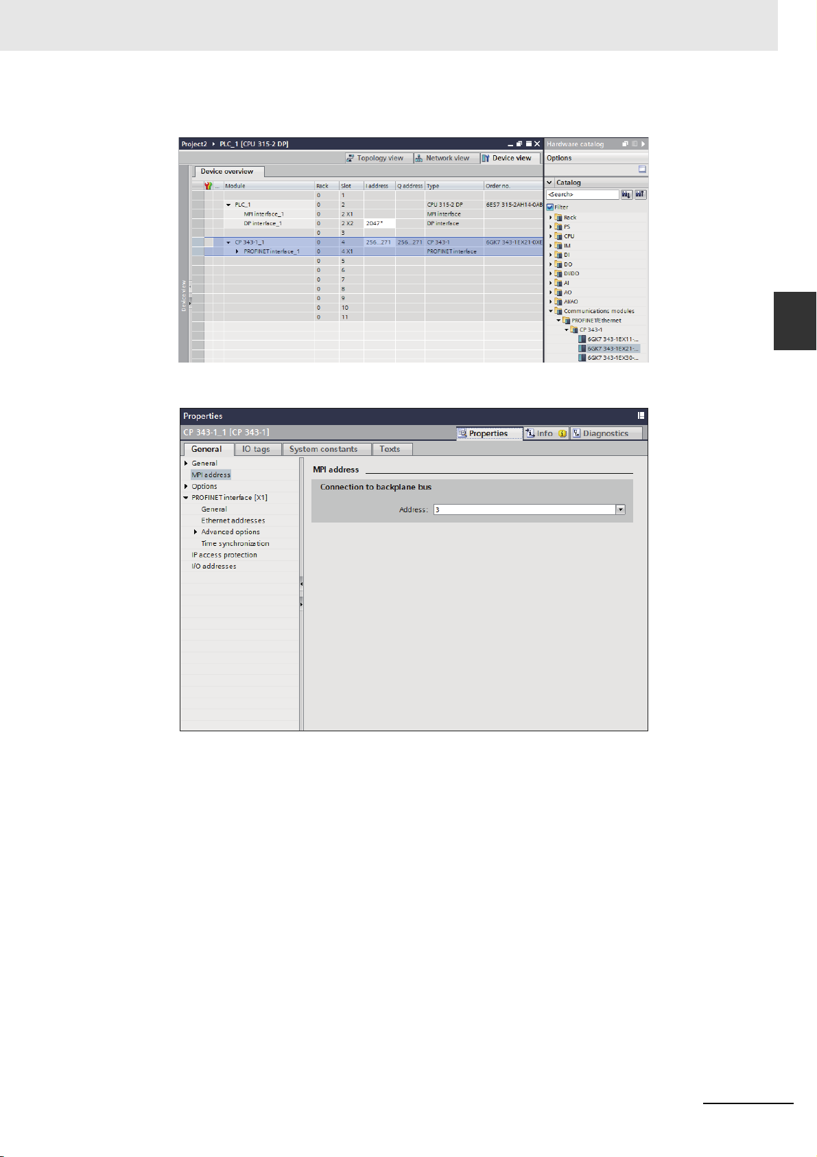
2 Connecting to SIEMENS PLCs
3
Select the Model from [CP 343-1] - [Hardware catalog] and double-click on the Model.
4
Click the [General] tab - [MPI address]. Set the [Connection to backplane bus] - [Address] to "3".
2-3 Communication Parameter Setting
2
2-3-4 SIEMENS S7-300 Ethernet (TCP Slave)
NB-series Programmable Terminals Host Connection Manual (V108)
2-21
Page 56
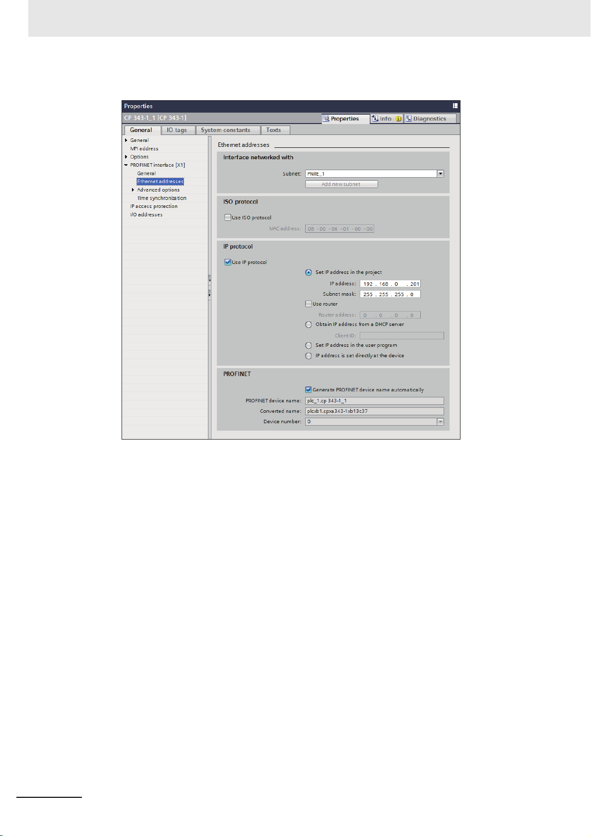
2 Connecting to SIEMENS PLCs
5
Click the [General] tab - [Ethernet addresses]. Make settings IP address and others.
6
Download the settings to the PLC.
2-22
NB-series Programmable Terminals Host Connection Manual (V108)
Page 57
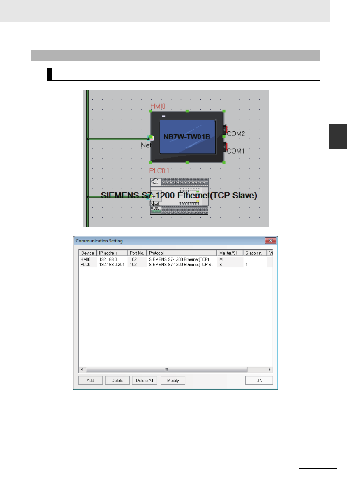
2 Connecting to SIEMENS PLCs
2-3-5 SIEMENS S7-1200 Ethernet (TCP Slave)
PT Settings
2-3 Communication Parameter Setting
2
2-3-5 SIEMENS S7-1200 Ethernet (TCP Slave)
NB-series Programmable Terminals Host Connection Manual (V108)
2-23
Page 58

2 Connecting to SIEMENS PLCs
PLC Settings
Make settings of the PLC using SIMATIC STEP 7 (TIA Portal).
1
Double-click the [General] tab - [PROFINET interface] - [Ethernet addresses] and set IP
address and others.
2
Transfer the set descriptions to the PLC. If you transfer the descriptions for the first time, select
the [Extended download to device] and check the [Show All compatible devices] check box.
2-24
NB-series Programmable Terminals Host Connection Manual (V108)
Page 59
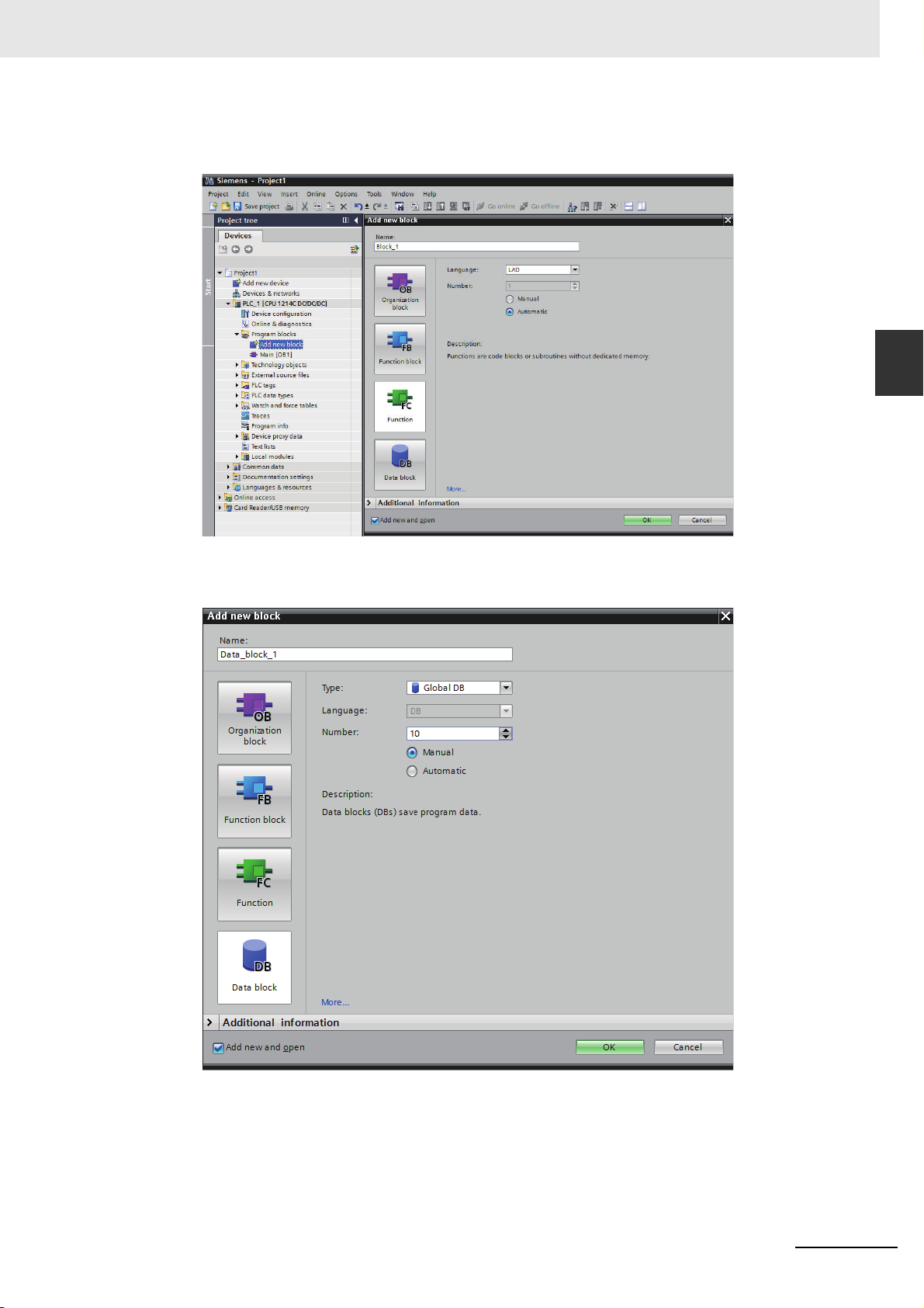
3
Create a Data block.
Double-click the [Project tree] - [Add new block].
2 Connecting to SIEMENS PLCs
2-3 Communication Parameter Setting
2
2-3-5 SIEMENS S7-1200 Ethernet (TCP Slave)
4
Click the [Data Block].
Example: If you should create a new Data block DB10, make settings as below.
NB-series Programmable Terminals Host Connection Manual (V108)
2-25
Page 60

2 Connecting to SIEMENS PLCs
Precautions for Correct Use
Precautions for Correct Use
• If you use the Data block, the data type of the NB and the PLC should be the same. For
instance, if the Data type of the PLC is REAL, the storing data type of the numeric input component should be Float.
• When you define the Data block, secure the larger area than the one used for the NB. For
instance, in order to use DB5.DBW32 in the NB, you need to secure DB5.DBW34 or later for
the PLC.
• If you use the data block, do not check in the check box, [Properties] - [Attributes] - [Only store
in load memory].
2-26
NB-series Programmable Terminals Host Connection Manual (V108)
Page 61

2 Connecting to SIEMENS PLCs
2-4 Supported Registers
2-4-1 SIEMENS S7-200
Device Bit Address Word Address Format Notes
SCR Nodes S.B 0.0~31.7 ------ DD.O
Special Memory Bit SM.B 0.0~549.7 ------ DDD.O
Counter Bit Cnt 0~255 ------ DDD.O
Counter Bit Tim 0~255 ------ DDD.O
Variable Memory Nodes V.B 0.0~10238.7 ------ DDDDD.O
Internal Memory Bit M.B 0.0~31.7 ------ DD.O
Discrete Output and Map Register Nodes Q.B 0.0~15.7 ------ DD.O
Discrete Input and Map Register Nodes I.B 0.0~15.7 ------ DD.O
Analog Output ------ AQW 0~62 DD
Analog Input: ------ AIW 0~62 DD
SCR (32-bit) ------ SD 0~28 DD
SCR ------ SW 0~30 DD
Special Memory Registers (32-bit) ------ SMD 0~546 DDD
Special Memory Registers ------ SMW 0~548 DDD
Internal Memory Bit (32-bit) ------ MD 0~28 DD
Internal Memory ------ MW 0~30 DD
Discrete Output and Map Registers (32-bit) ------ QD 0~12 DD
Discrete Output and Map Registers ------ QW 0~14 DD
Discrete Input and Map Registers (32-bit) ------ ID 0~12 DD
Discrete Input and Map Registers ------ IW 0~14 DD
Counter PV ------ Cnt 0~255 DDD
Timer PV ------ Tim 0~255 DDD
Variable Memory (32-bit) ------ VD 0~10236 DDDDD
Variable Memory ------ VW 0~10238 DDDDD
2-4 Supported Registers
2
2-4-1 SIEMENS S7-200
Note The initial addresses of VW and VD must be even.
Address format description: D: decimal, O: octonary, H: hexadecimal.
NB-series Programmable Terminals Host Connection Manual (V108)
2-27
Page 62

2 Connecting to SIEMENS PLCs
2-4-2 SIEMENS S7-300/400 (PC Adapter Direct)
Device Bit Address Word Address Format Notes
External Input Nodes I 0.0~511.7 ------ DDDD.O
External Output Nodes Q 0.0~511.7 ------ DDDD.O
Internal Auxiliary Nodes M 0.0~4095.7 ------ DDDD.O
Data Register Nodes DBm.DBX 0~65535.7 ------ DDDDD.O m: 10 to 29
Data Registers ------ DBm.DBW 0~65534 DDDDD m: 10 to 60
Data Registers (32-bit) ------ DBm.DBD 0~65532 DDDDD m: 10 to 60
Internal Registers ------ MW 0~2046 DDDD
Internal Registers (32-bit) ------ MD 0~2044 DDDD
External Output Registers ------ QW 0~126 DDD
External Output Registers (32-bit) ------ QD 0~124 DDD
External Input Registers ------ IW 0~126 DDD
External Input Registers (32-bit) ------ ID 0~124 DDD
Note The initial addresses of DBm.DBW and DBm.DBD must be even.
Address format description: D: decimal, O: octonary, H: hexadecimal.
2-4-3 SIEMENS S7-200 (Smart) Ethernet (TCP Slave)
Device Bit Address Word Address Format Notes
Discrete Input and Map Register Nodes I.B 0.0~31.7 ------ DD.O
Internal Memory Bit M.B 0.0~31.7 ------ DD.O
Discrete Output and Map Register Nodes Q.B 0.0~31.7 ------ DD.O
SCR Nodes S.B 0.0~31.7 ------ DD.O
Special Memory Bit SM.B 0.0~1535.7 ------ DDDD.O
Variable Memory Nodes V.B 0.0~8191.7 ------ DDDD.O
Analog Inputs ------ AIW 0~110 DDD
Analog Outputs ------ AQW 0~110 DDD
Discrete Input and Map Registers (32-bit) ------ ID 0~28 DD
Discrete Input and Map Registers ------ IW 0~30 DD
Internal Memory (32-bit) ------ MD 0~28 DD
Internal Memory ------ MW 0~30 DD
Discrete Output and Map Registers (32-bit) ------ QD 0~28 DD
Discrete Output and Map Registers ------ QW 0~30 DD
SCR (32-bit) ------ SD 0~28 DD
Special Memory Registers (32-bit) ------ SMD 0~1532 DDDD
Special Memory Registers ------ SMW 0~1534 DDDD
SCR ------ SW 0~30 DD
Variable Memory (32-bit) ------ VD 0~8188 DDDD
Variable Memory ------ VW 0~8190 DDDD
Note When you access word access and double word access memories, always specify even address.
2-28
NB-series Programmable Terminals Host Connection Manual (V108)
Page 63

2 Connecting to SIEMENS PLCs
2-4-4 SIEMENS S7-300 Ethernet (TCP Slave)
Device Bit Address Word Address Format Note
Data Register Nodes DBm_DBX
0.0~65535.7
Data Register Nodes DBn_DBX
100000.0~25565535.7
External Input Nodes I 0.0~2047.7 ------ DDDD.O
Internal Auxiliary Nodes M 0.0~8191.7 ------ DDDD.O
External Output Nodes Q 0.0~2047.7 ------ DDDD.O
Data Registers (8-bit) ------ DBm_DBB 0~65535 DDDDD m:1 to 10
Data Registers Nodes ------ DBm_DBB 0~65535 DDDDD m:1 to 10
Data Registers (32-bit) ------ DBm_DBD 0~65532 DDDDD m:1 to 10
Data Registers ------ DBm_DBW
Data Registers ------ DBn_DBB
Data Registers (32-bit) ------ DBn_DBD
Data Registers ------ DBn_DBW
External Output Nodes ------ IB 0~2047 DDDD
External Input Registers (32-bit) ------ ID 0~2044 DDDD
External Input Registers ------ IW 0~2046 DDDD
External Input Nodes ------ MB 0~8191 DDDD
Internal Registers (32-bit) ------ MD 0~8188 DDDD
Internal Registers ------ MW 0~8190 DDDD
Internal Assistant Nodes ------ QB 0~2047 DDDD
External Output Registers (32-bit) ------ QD 0~2044 DDDD
External Output Registers ------ QW 0~2046 DDDD
------ DDDDD.O m:1 to 10
------
0~65534
100000~25565535
100000~25565532
100000~25565534
DDDDDDDD.On:1 to 255
DDDDD m:1 to 10
DDDDDDDD n:1 to 255
DDDDDDDD n:1 to 255
DDDDDDDD n:1 to 255
2-4 Supported Registers
2
2-4-4 SIEMENS S7-300 Ethernet (TCP Slave)
Note 1 DBn_DBX, DBn_DBW, and DBn_DBD represent custom blocks. The top three digits of the Data block address indi-
cate block number. The other five digits after the block number indicate address. If the address part is less than five
digits, fill in '0's. For instance, if you access to DB20.DBX23.4, set DBn_DBX to 2000023.4.
2 When you access word access and double word access memories, always specify even address.
3 MB, IB, and QB do not support the signed integer number as data format.
4 If you define the Data block, secure the larger area than that used in the NB. For instance, if you use DB5.DBW32 in
the NB, you should secure DB5.DBW34 or later in the PLC.
5 When you access data block of double word, you cannot access the maximum address.
NB-series Programmable Terminals Host Connection Manual (V108)
2-29
Page 64

2 Connecting to SIEMENS PLCs
2-4-5 SIEMENS S7-1200 Ethernet (TCP Slave)
Device Bit Address Word Address Format Note
Data Register Nodes DBm_DBX
0.0~65535.7
Data Register Nodes DBn_DBX
100000.0~25565535.7
External Input Nodes I 0.0~1023.7 ------ DDDD.O
Internal Auxiliary Nodes M 0.0~8191.7 ------ DDDD.O
External Output Nodes Q 0.0~1023.7 ------ DDDD.O
Data Registers (32-bit) ------ DBm_DBD 0~65532 DDDDD m:1 to 10
Data Registers ------ DBm_DBW
Data Registers (32-bit) ------ DBn_DBD
Data Registers ------ DBn_DBW
External Input Registers (32-bit) ------ ID 0~1020 DDDD
External Input Registers ------ IW 0~1022 DDDD
Internal Registers (32-bit) ------ MD 0~8188 DDDD
Internal Registers ------ MW 0~8190 DDDD
External Output Registers (32-bit) ------ QD 0~1020 DDDD
External Output Registers ------ QW 0~1022 DDDD
------ DDDDD.O m:1 to 10
------
0~65534
100000~25565532
100000~25565534
DDDDDDDD.On:1 to 255
DDDDD m:1 to 10
DDDDDDDD n:1 to 255
DDDDDDDD n:1 to 255
Note 1 The data register of the NB-Designer observes the absolute address of the Data block instead of the S7-1200 global
symbol data block.
2 DBn_DBX, DBn_DBW, and DBn_DBD represent custom blocks. The top three digits of the Data block address indi-
cate block number. The other five digits after the block number indicate address. If the address part is less than five
digits, fill in '0's. For instance, if you access to DB20.DBX23.4, set DBn_DBX to 2000023.4.
3 When you access word access and double word access memories, always specify even address.
4 If you define the data block, secure the larger area than that used in the NB. For instance, if you use DB5.DBW32 in
the NB, you should secure DB5.DBW34 or later in the PLC.
5 When you access data block of double word, you cannot access the maximum address.
2-30
NB-series Programmable Terminals Host Connection Manual (V108)
Page 65

2-5 Cable Fabrication
PT (COM2)
Pin No.
6
8
9
Signal
RDB+
RDA-
SG
D-Sub
9Pin
(Female)
PLC
Pin No.
3
8
5
Signal
D+
D-
GND
D-Sub
9Pin
(Female)
4
5
Terminal R1
Terminal R2
When Using SIEMENS S7-200 Communication Protocol
RS232 Communication Cable
Use RS-232/PPI multi-host cable and self-made RS232 cable manufactured by SIEMENS to
communicate with PT.
• Self-made RS-232 Cable
PT (COM1/COM2)
D-Sub
9Pin
(Female)
Signal
SD
RD
SG
RS485 Communication Cable
Pin No.
2
3
9
2 Connecting to SIEMENS PLCs
RS-232/PPI cable connector
Pin No.
2
3
5
Signal
RXD
TXD
GND
(Female)
2-5 Cable Fabrication
2
D-Sub
9Pin
When Using SIEMENS S7-300/400 (PC Adapter Direct)
Communication Protocol
RS232 Communication Cable
Use MPI-Adapter SSW7, RS232 (Order No.700-751-1VK21) manufactured by Helmholz and RS232
cable to communicate to PT.
PT (COM1/COM2)
D-Sub
9Pin
(Female)
Signal
SD
RD
SG
Pin No.
2
3
9
MPI-Adapter RS-232 cable
connector
Pin No.
2
3
4
5
6
7
8
Signal
RXD
TXD
DTR
GND
DSR
RTS
CTS
D-Sub
9Pin
(Male)
NB-series Programmable Terminals Host Connection Manual (V108)
2-31
Page 66

2 Connecting to SIEMENS PLCs
2-32
NB-series Programmable Terminals Host Connection Manual (V108)
Page 67

Connecting to Mitsubishi PLCs
This section describes the connection to Mitsubishi PLCs.
3-1 Serial Port and Ethernet . . . . . . . . . . . . . . . . . . . . . . . . . . . . . . . . . . . . . . . . 3-2
3-1-1 Serial Port . . . . . . . . . . . . . . . . . . . . . . . . . . . . . . . . . . . . . . . . . . . . . . . . . . . . 3-2
3-1-2 Ethernet . . . . . . . . . . . . . . . . . . . . . . . . . . . . . . . . . . . . . . . . . . . . . . . . . . . . . . 3-3
3-2 Communication Setting and Cable Connection . . . . . . . . . . . . . . . . . . . . . 3-5
3-2-1 Serial Port . . . . . . . . . . . . . . . . . . . . . . . . . . . . . . . . . . . . . . . . . . . . . . . . . . . . 3-5
3-2-2 Ethernet . . . . . . . . . . . . . . . . . . . . . . . . . . . . . . . . . . . . . . . . . . . . . . . . . . . . . . 3-6
3-3 Communication Setting . . . . . . . . . . . . . . . . . . . . . . . . . . . . . . . . . . . . . . . . . 3-7
3-3-1 When Using Mitsubishi FX1S, Mitsubishi FX1N/2N/3G and Mitsubishi FX3U
Communication Protocols . . . . . . . . . . . . . . . . . . . . . . . . . . . . . . . . . . . . . . . . 3-7
3-3-2 When Using Mitsubishi FX-485ADP/485BD/232BD (Multi-station)
Communication Protocols . . . . . . . . . . . . . . . . . . . . . . . . . . . . . . . . . . . . . . . . 3-9
3-3-3 When Using FX2N-10GM/20GM Communication Protocol . . . . . . . . . . . . . . 3-12
3-3-4 When Using Mitsubishi Q00J (CPU Port) Communication Protocol . . . . . . . 3-13
3-3-5 When Using Mitsubishi Q series (CPU Port) Communication Protocol . . . . . 3-13
3-3-6 When Using Mitsubishi Q06H Communication Protocol . . . . . . . . . . . . . . . . 3-14
3-3-7 When Using Mitsubishi Q_QnA (Link Port) Communication Protocol . . . . . . 3-15
3-3-8 When Using Mitsubishi FX Series Ethernet(TCP Slave) Communication
Protocol . . . . . . . . . . . . . . . . . . . . . . . . . . . . . . . . . . . . . . . . . . . . . . . . . . . . . 3-20
3-3-9 When Using Mitsubishi QnA 3EBin Ethernet (TCP Slave) Communication
Protocol . . . . . . . . . . . . . . . . . . . . . . . . . . . . . . . . . . . . . . . . . . . . . . . . . . . . . 3-23
3-3-10 When Using Mitsubishi QJ71E71 EtherNet Slave Communication
Protocol . . . . . . . . . . . . . . . . . . . . . . . . . . . . . . . . . . . . . . . . . . . . . . . . . . . . . 3-26
3
3-4 Supported Registers . . . . . . . . . . . . . . . . . . . . . . . . . . . . . . . . . . . . . . . . . . 3-29
3-5 Cable Fabrication . . . . . . . . . . . . . . . . . . . . . . . . . . . . . . . . . . . . . . . . . . . . . 3-35
NB-series Programmable Terminals Host Connection Manual (V108)
3-1
Page 68

3 Connecting to Mitsubishi PLCs
3-1 Serial Port and Ethernet
3-1-1 Serial Port
Series CPU
FXCPU FX1S RS422 on the CPU unit Mitsubishi FX1S *2
FX1N RS422 on the CPU unit Mitsubishi FX1N/2N/3G *2
FX2N RS422 on the CPU unit Mitsubishi FX1N/2N/3G *2
FX1NC RS422 on the CPU unit Mitsubishi FX1N/2N/3G *2
FX2NC RS422 on the CPU unit Mitsubishi FX1N/2N/3G *2
FX2N-10GM
FX2N-20GM
FX3U
FX3UC
FX3S
FX3G
FX3GC
MELSEC Q Q00JCPU RS232 on the CPU unit Mitsubishi Q00J (CPU Port)
Q00CPU
Q01CPU
Q02CPU
Q02HCPU
Q12HCPU
Q25HCPU
(The products in ( ) are also needed)
FX2NC-485-ADP (FX1N-CNV-BD)
FX0N-485-ADP (FX1N-CNV-BD)
FX1N--BD
FX2NC-485-ADP (FX1N-CNV-BD)
FX0N-485-ADP (FX1N-CNV-BD)
FX1N--BD
FX2NC-485-ADP (FX1N-CNV-BD)
FX0N-485-ADP (FX1N-CNV-BD)
FX2N--BD
FX2NC-485-ADP (FX1N-CNV-BD)
FX0N-485-ADP (FX1N-CNV-BD)
FX2NC-485-ADP (FX1N-CNV-BD)
FX0N-485-ADP (FX1N-CNV-BD)
RS422 on the CPU unit Mitsubishi FX2N_10GM/20GM
RS422 on the CPU unit Mitsubishi FX3U *2
FX3U--BD
FX3U-485-ADP (FX3U-CNV_BD)
RS422 on the CPU unit Mitsubishi FX1N/2N/3G *2
FX3G--BD
FX3U-485-ADP (FX3G-CNV-ADP)
QJ71C24
QJ71C24-R2
QJ71C24N
QJ71C24N-R2
QJ71C24N-R4
QJ71C24
QJ71C24-R2
QJ71C24N
QJ71C24N-R2
QJ71C24N-R4
RS232 on the CPU unit Mitsubishi Q Series (CPU Port)
QJ71C24
QJ71C24-R2
QJ71C24N
QJ71C24N-R2
QJ71C24N-R4
Link Module
Driver
Mitsubishi FX1S *2
Mitsubishi FX-485ADP/485BD/232BD
(Multi-station) *1
Mitsubishi FX1N/2N/3G *2
Mitsubishi FX-485ADP/485BD/232BD
(Multi-station) *1
Mitsubishi FX1S *2
Mitsubishi FX-485ADP/485BD/232BD
(Multi-station) *1
Mitsubishi FX1N/2N/3G *2
Mitsubishi FX-485ADP/485BD/232BD
(Multi-station)
Mitsubishi FX1N/2N/3G *2
Mitsubishi FX-485ADP/485BD/232BD
(Multi-station)
Mitsubishi FX3U *2
Mitsubishi FX-485ADP/485BD/232BD
(Multi-station) *1
Mitsubishi FX-485ADP/485BD/232BD
(Multi-station) *1
Mitsubishi Q_QnA (Link Port)
Mitsubishi Q_QnA (Link Port)
Mitsubishi Q_QnA (Link Port)
3-2
NB-series Programmable Terminals Host Connection Manual (V108)
Page 69
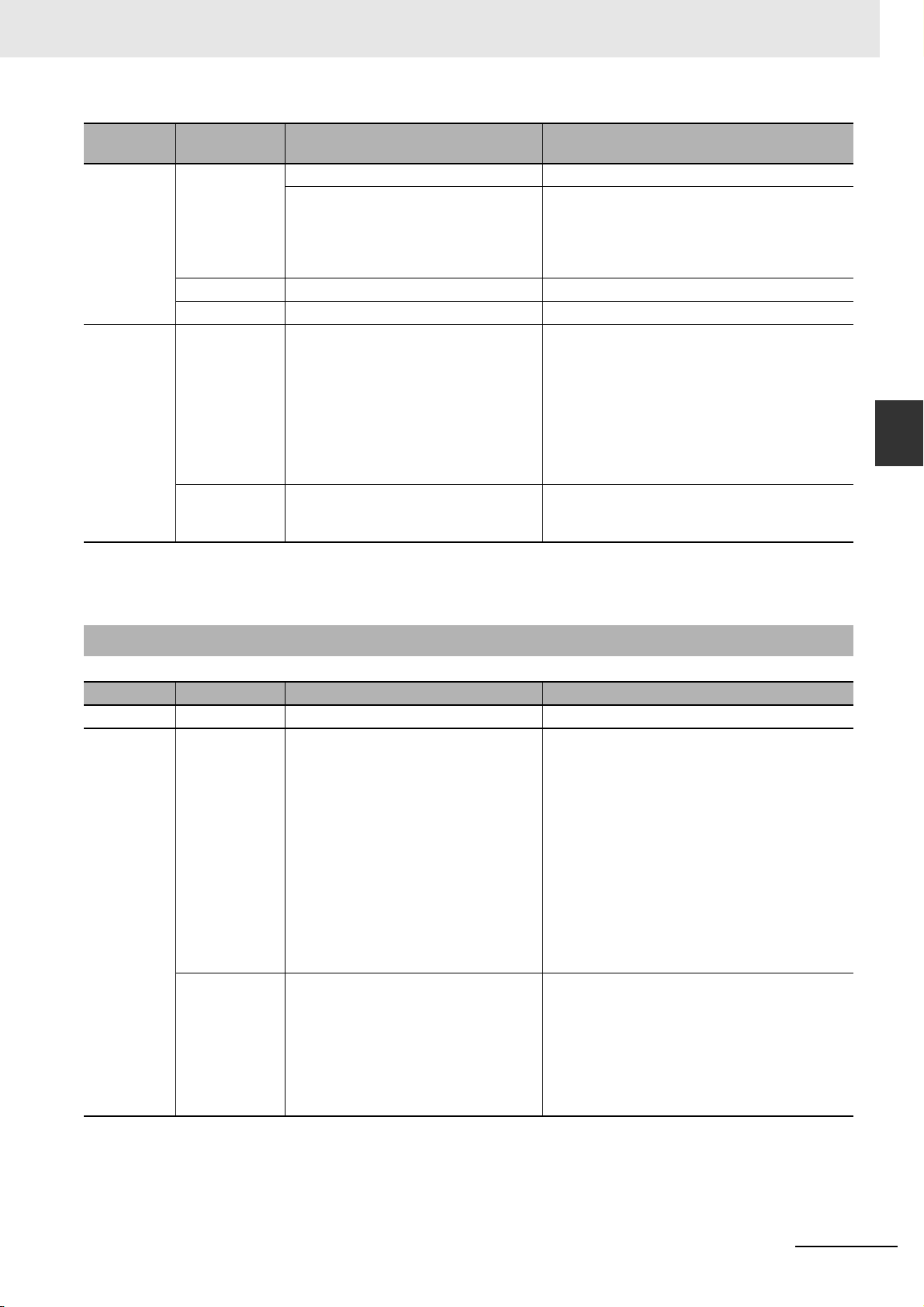
3 Connecting to Mitsubishi PLCs
Series CPU
MELSEC Q Q06HCPU RS232 on the CPU unit Mitsubishi Q06H
Q00UJCPU RS232 on the CPU unit Mitsubishi Q_QnA (Link Port)
Q06UDHCPU RS232 on the CPU unit Mitsubishi Q Series (CPU Port)
MELSEC L L02CPU
L02CPU-P
L02SCPU-P
L06CPU
L06CPU-P
L26CPU
L26CPU-P
L26CPU-BT
L26CPU-PBT
L02SCPU RS232C port on CPU Unit
*1 This protocol supports Multiple Station No..
*2 This protocol does not support Multiple Station No..
(The products in ( ) are also needed)
QJ71C24
QJ71C24-R2
QJ71C24N
QJ71C24N-R2
QJ71C24N-R4
LJ71C24
LJ71C24-R2
LJ71C24
LJ71C24-R2
Link Module
Mitsubishi Q_QnA (Link Port)
Mitsubishi Q_QnA (Link Port)
Mitsubishi Q_QnA (Link Port)
Driver
3-1 Serial Port and Ethernet
3
3-1-2 Ethernet
3-1-2 Ethernet
Series CPU Link Module Driver
FXCPU FX3U FX3U-ENET-L Mitsubishi FX Series Ethernet (TCP Slave)
MELSEC Q Q03UDE
Q04UDEH
Q06UDEH
Q10UDEH
Q13UDEH
Q20UDEH
Q26UDEH
Q50UDEH
Q100UDEH
Q03UDV
Q04UDV
Q06UDV
Q13UDV
Q26UDV
Q00CPU
Q00JCPU
Q01CPU
Q02CPU
Q02HCPU
Q06HCPU
Q12HCPU
Q25HCPU
Ethernet Port on CPU Unit Mitsubishi QnA 3EBin Ethernet (TCP Slave)
QJ71E71-100 Mitsubishi QJ71E71 EtherNet Slave
NB-series Programmable Terminals Host Connection Manual (V108)
3-3
Page 70

3 Connecting to Mitsubishi PLCs
Series CPU Link Module Driver
MELSEC L L02CPU
L02CPU-P
L06CPU
L06CPU-P
L26CPU
L26CPU-P
L26CPU-BT
L26CPU-PBT
L02SCPU
L02SCPU-P
Ethernet Port on CPU Unit Mitsubishi QnA 3EBin Ethernet (TCP Slave)
LJ71E71-100 Mitsubishi QJ71E71 EtherNet Slave
LJ71E71-100 Mitsubishi QJ71E71 EtherNet Slave
3-4
NB-series Programmable Terminals Host Connection Manual (V108)
Page 71

3 Connecting to Mitsubishi PLCs
3-2 Communication Setting and Cable
Connection
3-2-1 Serial Port
Series CPU Link Module COMM Type Parameter Cable
FXCPU FX1S
FX1N
FX2N
FX1NC
FX2NC
FX2N-10GM
FX2N-20GM
FX3G
FX3GC
FX3UC
FX3U
FX3S
MELSEC Q Q00JCPU
Q02CPU
Q02HCPU
Q12HCPU
Q25HCPU
Q06HCPU
Q00UJ CPU
Q06UDHCPU
Q00JCPU
Q00CPU
Q01CPU
Q02CPU
Q02HCPU
Q12HCPU
Q25HCPU
Q06HCPU
MELSEC L L02SCPU RS232 on the CPU unit RS232
L02CPU
L02CPU-P
L02SCPU
L02SCPU-P
L06CPU
L06CPU-P
L26CPU
L26CPU-P
L26CPU-BT
L26CPU-PBT
RS422 on the CPU unit RS422 Refer to Section 3-3 Self-made cable
RS232 Module RS232
RS485 Module RS422
RS422 on the CPU unit RS422
RS485 Module RS422
RS422 on the CPU unit RS422
RS422 on the CPU unit RS422
RS232 Module RS232
RS485 Module RS422
RS422 on the CPU unit RS422
RS232 Module RS422
RS485 Module RS422
RS232 on the CPU unit RS232
QJ71C24
QJ71C24-R2
QJ71C24N
QJ71C24N-R2
QJ71C24
QJ71C24N
QJ71C24N-R4
LJ71C24
LJ71C24-R2
LJ71C24 RS422
RS232
RS422
RS232
required
3-2 Communication Setting and Cable Connection
3
3-2-1 Serial Port
NB-series Programmable Terminals Host Connection Manual (V108)
3-5
Page 72

3 Connecting to Mitsubishi PLCs
3-2-2 Ethernet
Series CPU Link Module COMM Type Parameter Cable
FXCPU FX3U FX3U-ENET-L - Refer to Section 3-3 Network Cable
MELSEC Q Q00JCPU
Q00CPU
Q01CPU
Q02CPU
Q02HCPU
Q12HCPU
Q25HCPU
Q26UDVCPU
Q03UDECPU
Q04UDEHCPU
Q06UDEHCPU
Q10UDEHCPU
Q13UDEHCPU
Q20UDEHCPU
Q26UDEHCPU
Q100UDEHCPU
MELSEC L L02SCPU
L02SCPU-P
L02CPU
L02CPU-P
L06CPU
L06CPU-P
L26CPU
L26CPU-P
L26CPU-BT
L26CPU-PBT
QJ71E71-100 -
Ethernet Port on CPU Unit -
LJ71E71-100 -
Ethernet Port on CPU Unit
LJ71E71-100
-
3-6
NB-series Programmable Terminals Host Connection Manual (V108)
Page 73

3 Connecting to Mitsubishi PLCs
3-3 Communication Setting
3-3-1 When Using Mitsubishi FX1S, Mitsubishi FX1N/2N/3G and
Mitsubishi FX3U Communication Protocols
PT Settings
PT default communication parameters: 9600bps (Baud Rate), 7 (Data Bit), even (Parity Check), 1 (Stop
Bit) and 0 (PLC Station No.)
The PLC Communication Time Out, Max interval of word (bit) block pack, Max size of word(bit) block
package on the right of the dialog box vary with PLC protocols. Generally the defaults are selected.
Note This protocol can be used when communicating with the PLC through the programming port of the CPU and
the Functions Extension board. This Protocol does not support Multiple Station No. of the Function Extension board. The supporting Baud Rates are as follows. If other Baud Rates than these are selected, the communication is unavailable.
9600bps, 115200bps: FX3G, FX3GC, FX3S, FX3U, FX3UC
9600bps fixed: other CPUs than above
RS422 Communication
3-3 Communication Setting
3
3-3-1 When Using Mitsubishi FX1S, Mitsubishi FX1N/2N/3G and Mitsubishi FX3U Communication Protocols
NB-series Programmable Terminals Host Connection Manual (V108)
3-7
Page 74
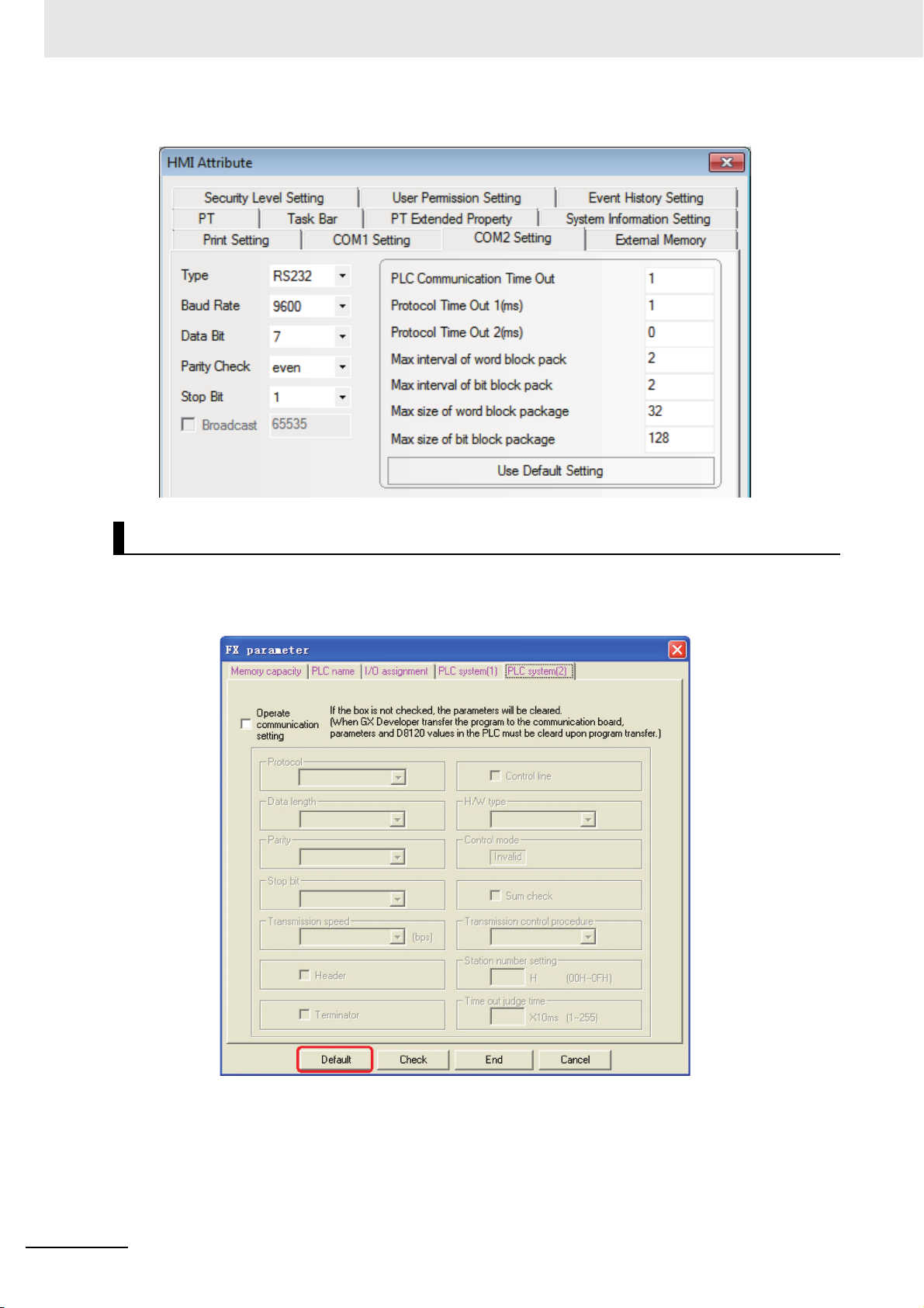
3 Connecting to Mitsubishi PLCs
RS232 Communication
PLC Settings
The PLC setting is as shown below when Mitsubishi FX1S, Mitsubishi FX1N/2N/3G and Mitsubishi
FX3U communication protocols are used:
Click the [Default] button to make settings without checking the [Communication Setting]:
3-8
Note 1 The communication protocols such as Mitsubishi FX1S, Mitsubishi FX1N/2N/3G and Mitsubishi FX3U etc.
can be selected according to PLC model if the Station No. is not used when the communication is realized
through the communication function expansion board.
2 Make sure the value of communication format D8120 is 0 when the communication is realized through the
communication function expansion board.
NB-series Programmable Terminals Host Connection Manual (V108)
Page 75
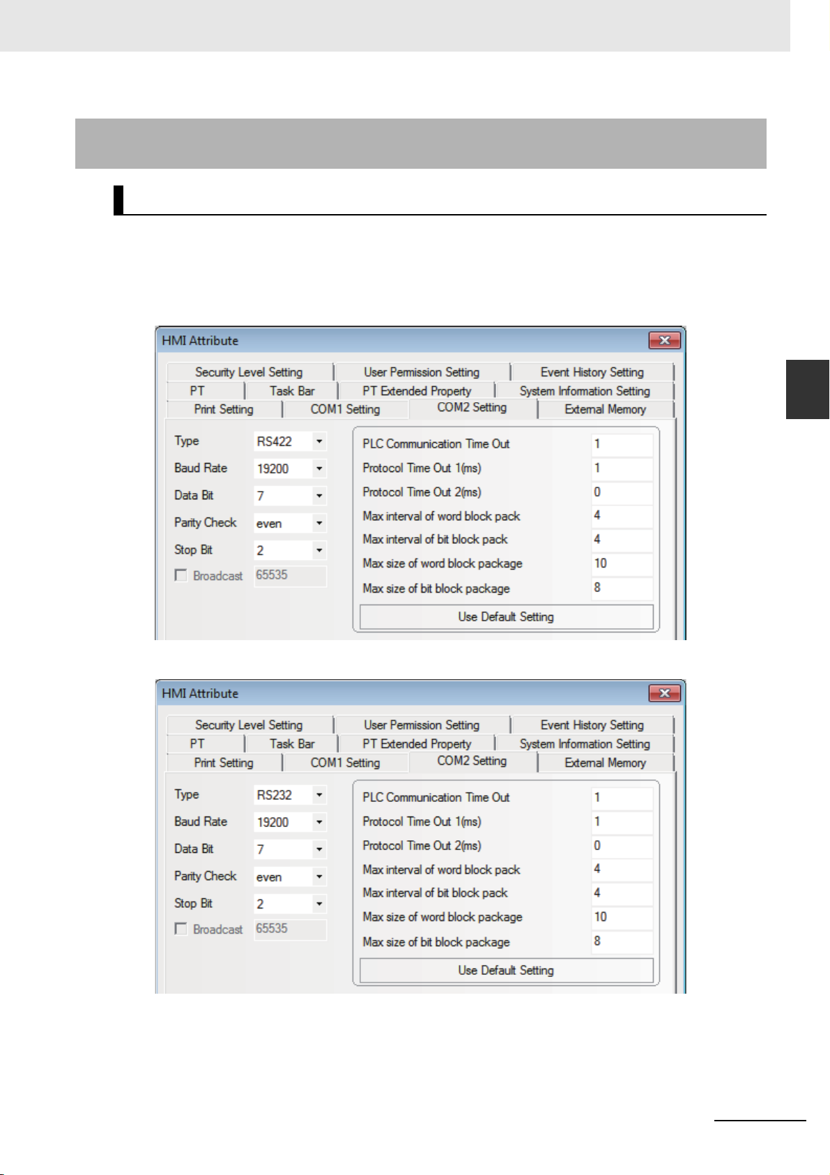
3 Connecting to Mitsubishi PLCs
3-3-2 When Using Mitsubishi FX-485ADP/485BD/232BD (Multi-station)
Communication Protocols
PT Settings
PT default communication parameters: 19200bps (Baud Rate), 7(Data Bit), even (Parity Check), 2
(Stop Bit) and 0 (PLC Station No.)
Note: The protocols are only applicable to PLCs communicating through communication function
expansion board and support Multiple Station No. and Baud Rate settings.
RS422 Communication
3-3 Communication Setting
3
3-3-2 When Using Mitsubishi FX-485ADP/485BD/232BD (Multi-station) Communication Protocols
RS232 Communication
NB-series Programmable Terminals Host Connection Manual (V108)
3-9
Page 76

3 Connecting to Mitsubishi PLCs
PLC Settings
The PLC setting is as shown below when FX-485ADP/485BD/232BD (Multi-station) communication
protocols are used:
1
Double-click the [PLC Parameter] under [Project Data List] in GX Developer software.
2
Open the [FX Parameter] dialog box.
(1) FX1S/FX1N/FX2N/3G Series PLC
3-10
Check the [Operate communication setting] option.
Note 1 Set the parameters as follows.
The [Dedicated Protocol] is selected for Protocol, the [Sum Check] is checked, and [Form4]
is selected for the Transmission Control Sequence.
2 Set the [H/W Type] as follows.
“Regular/RS-232C” is selected when FX-232-BD communications is used or “RS-485” is
selected when FX-232-BD or FX-485-BD/FX-485-ADP communications is used.
NB-series Programmable Terminals Host Connection Manual (V108)
Page 77

(2) FX3U/3UC Series PLC
3 Connecting to Mitsubishi PLCs
3-3 Communication Setting
3
3-3-2 When Using Mitsubishi FX-485ADP/485BD/232BD (Multi-station) Communication Protocols
Check the [Operate communication setting] option.
Note 1 The [CH1] should be selected for FX3U/3UC Series PLC.
2 Set the parameters as follows.
[Dedicated Protocol] is selected for Protocol, [Sum Check] is checked, and [Form4] is
selected for the Transmission Control Sequence.
3 Set the [H/W Type] as follows.
“Regular/RS-232C” is selected when FX-232-BD communications is used or “RS-485” is
selected when FX-485-BD/FX-485-ADP communications is used.
Aside from using [FX Parameter], the user can use the special data register D8120 in PLC
to set the communication parameters for PLC.
Special Data Registers Descriptions
D8120 Communication format
D8121 Station No. setting
D8129 Data network out-time counting
Applicable to FX3U/3UC and other FX Series PLCs using CH1
• For example:
If the PLC communication parameters are: 9600bps (Baud Rate), 7 (Data Bit), even (Parity
Check), 2 (Stop Bit), 1(PLC Station No.), RS485 (Communication Method) and 1 (PLC Communication Time Out), then D8120=0xE08E,
D8121=1,
and D8129=1.
Note The settings will be valid when the PLC is restarted after the D8120 setting is modified.
NB-series Programmable Terminals Host Connection Manual (V108)
3-11
Page 78

3 Connecting to Mitsubishi PLCs
.
3-3-3 When Using FX2N-10GM/20GM Communication Protocol
PT Settings
PT default communication parameters: 9600bps (Baud Rate), 8 (Data Bit), even (Parity Check), 1 (Stop
Bit) and 0 (PLC Station No.)
Note This protocol can be used when communicating with the PLC through the programming port of the CPU and
the Functions Extension board. The baud rate is fixed to 9600 bps. If the baud rate is set to the other speed,
the communications cannot be available. The protocol does not support the multiple station No. of the Functions Extension board.
RS232 Communication
RS422 Communication
3-12
NB-series Programmable Terminals Host Connection Manual (V108)
Page 79

3 Connecting to Mitsubishi PLCs
3-3-4 When Using Mitsubishi Q00J (CPU Port) Communication
Protocol
PT Settings
PT default communication parameters: 19200bps (Baud Rate), 8 (Data Bit), odd (Parity Check), 1 (Stop
Bit) and 0 (PLC Station No.) (Multiple Station No. is not supported.)
RS232 Communication
3-3 Communication Setting
3
3-3-4 When Using Mitsubishi Q00J (CPU Port) Communication Protocol
Note There is no need to set PLC baud rate that will automatically vary with the baud rate set by PT.
3-3-5 When Using Mitsubishi Q series (CPU Port) Communication
Protocol
PT Settings
PT default communication parameters: 115200bps (Baud Rate), 8 (Data Bit), odd (Parity Check), 1
(Stop Bit) and 0 (PLC Station No.) (Multiple Station No. is not supported.)
NB-series Programmable Terminals Host Connection Manual (V108)
3-13
Page 80

3 Connecting to Mitsubishi PLCs
RS232 Communication
Note There is no need to set PLC baud rate that will automatically vary with the baud rate set by PT.
3-3-6 When Using Mitsubishi Q06H Communication Protocol
PT Settings
PT default communication parameters: 115200bps (Baud Rate), 8 (Data Bit), odd (Parity Check), 1
(Stop Bit) and 0 (PLC Station No.) (Multiple Station No. is not supported.)
RS232 Communication
3-14
Note There is no need to set PLC baud rate that will automatically vary with the baud rate set by PT.
NB-series Programmable Terminals Host Connection Manual (V108)
Page 81

3 Connecting to Mitsubishi PLCs
3-3-7 When Using Mitsubishi Q_QnA (Link Port) Communication
Protocol
PT Settings
PT default communication parameters: 9600bps (Baud Rate), 8 (Data Bit), odd (Parity Check), 1 (Stop
Bit) and 0 (PLC Station No.)
RS232 Communication
3-3 Communication Setting
3
3-3-7 When Using Mitsubishi Q_QnA (Link Port) Communication Protocol
RS422 Communication
NB-series Programmable Terminals Host Connection Manual (V108)
3-15
Page 82

3 Connecting to Mitsubishi PLCs
PLC Settings
The PLC settings is as shown below when Mitsubishi Q_QnA (Link Port) or Mitsubishi Melsec Q
communication protocols are used:
Communication through CPU Port
Communication through C24 Serial Port Communication Module
1
Open [Parameter] on Project Data List and double-click [PLC parameter], and select [I/O
assignment] after the [Qn (H) Parameter] dialog box is opened.
3-16
NB-series Programmable Terminals Host Connection Manual (V108)
Page 83

2
Click the [Type] dropdown list to select the [Intelli.] option.
3 Connecting to Mitsubishi PLCs
3-3 Communication Setting
3
3-3-7 When Using Mitsubishi Q_QnA (Link Port) Communication Protocol
3
Click the [Switch setting] button and make settings as shown below:
NB-series Programmable Terminals Host Connection Manual (V108)
3-17
Page 84

3 Connecting to Mitsubishi PLCs
Bit
0
1
2
3
4
5
6
7
bps
4800
9600
19200
38400
57600
115200
Settings
04H
05H
07H
09H
0AH
0BH
Baud rate
CH1:Baud rate , transmission setting
Bit
15 8 7 0
transmission setting
Switch
Switch 1
CH1:Communication protocol
CH2:Baud rate,transmission setting (The same with the switch 1)
CH2:Communication protocol
Set the station number
Switch 2
Switch 3
Switch 4
Switch 5
MC protocol Form 5 Binary code
MC protocol Form 5 Binary code
0~31
0005H
0BEEH
0005H
000H
0BEEH
115Kbps
8bit
1bit
Even
[Example]Content
Content
Action set
Data bit
Parity check bit
Parity check
Stop bit
Sum check
Run write
Set to change
OFF
Independent
7
Reserved
Odd
1
Reserved
disable
disable
ON
Linked
8
Served
Even
2
Served
enable
enable
The attribute descriptions of Switch1, Switch2, Switch3, Switch4 and Switch5 are as shown below:
• Setting Example
The Switch3, Switch4 and Switch5 can be set as shown below if the CH2 RS422 communication
parameters and Station No. are set to 19200/8/Odd/1 and 0 respectively:
Setting Switch
Switch 3
Switch 4
Switch 5
Setting
Val ue
07E6
0005
0000
Setup Description
19200/8/With/Odd/1
Mode = Form 5
Station No. = 0
3-18
NB-series Programmable Terminals Host Connection Manual (V108)
Page 85

3 Connecting to Mitsubishi PLCs
The Switch1, Switch2 and Switch5 can be set as shown below if the CH1 RS232 communication
parameters and Station No. are set to 19200/8/Odd/1 and 0 respectively:
Setting Switch
Switch 1
Switch 2
Switch 5
Setting
Val ue
07E6
0005
0000
Setup Description
19200/8/With/Odd/1
Mode = Form 5
Station No. = 0
The difference between Mitsubishi Q_QnA (Link Port) protocol and Mitsubishi Melsec Q protocol:
• Mitsubishi Q_QnA (Link Port) protocol features fast communication speed.
• Mitsubishi Melsec Q protocol features slow communication speed.
3-3 Communication Setting
3
3-3-7 When Using Mitsubishi Q_QnA (Link Port) Communication Protocol
NB-series Programmable Terminals Host Connection Manual (V108)
3-19
Page 86

3 Connecting to Mitsubishi PLCs
3-3-8 When Using Mitsubishi FX Series Ethernet(TCP Slave)
Communication Protocol
PT Settings
The PT Network Settings are as shown below.
3-20
NB-series Programmable Terminals Host Connection Manual (V108)
Page 87

3 Connecting to Mitsubishi PLCs
PLC Settings
The PLC Settings when using Communication Protocol of Mitsubishi FX Series Ethernet (TCP Slave) is
as shown below.
1
Start-up Setting Tool, FX3U-ENET-L.
2
Click the [Operation Setting] to open [Ethernet Operation Setting].
3-3 Communication Setting
3
3-3-8 When Using Mitsubishi FX Series Ethernet(TCP Slave) Communication Protocol
Set the IP address to the same parameters as the PT settings.
Other settings should be the same as the dialog box as below.
NB-series Programmable Terminals Host Connection Manual (V108)
3-21
Page 88

3 Connecting to Mitsubishi PLCs
3
Click the [Open Setting] to open the [Ethernet Open Setting].
3-22
NB-series Programmable Terminals Host Connection Manual (V108)
Page 89
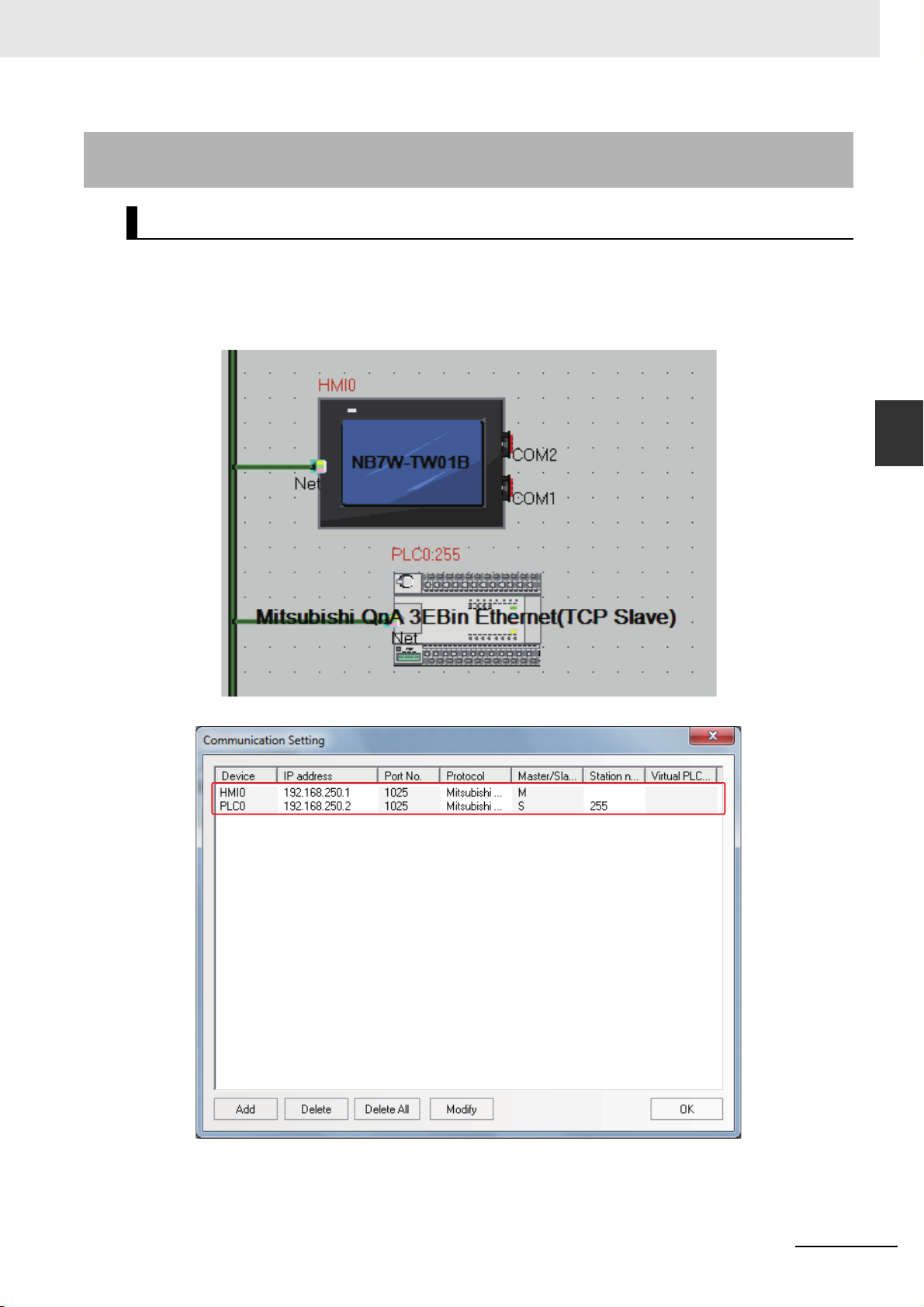
3 Connecting to Mitsubishi PLCs
3-3-9 When Using Mitsubishi QnA 3EBin Ethernet (TCP Slave)
Communication Protocol
PT Settings
The PT Network Settings are as shown below.
Note The Station No. is fixed to 255.
3-3 Communication Setting
3
3-3-9 When Using Mitsubishi QnA 3EBin Ethernet (TCP Slave) Communication Protocol
NB-series Programmable Terminals Host Connection Manual (V108)
3-23
Page 90
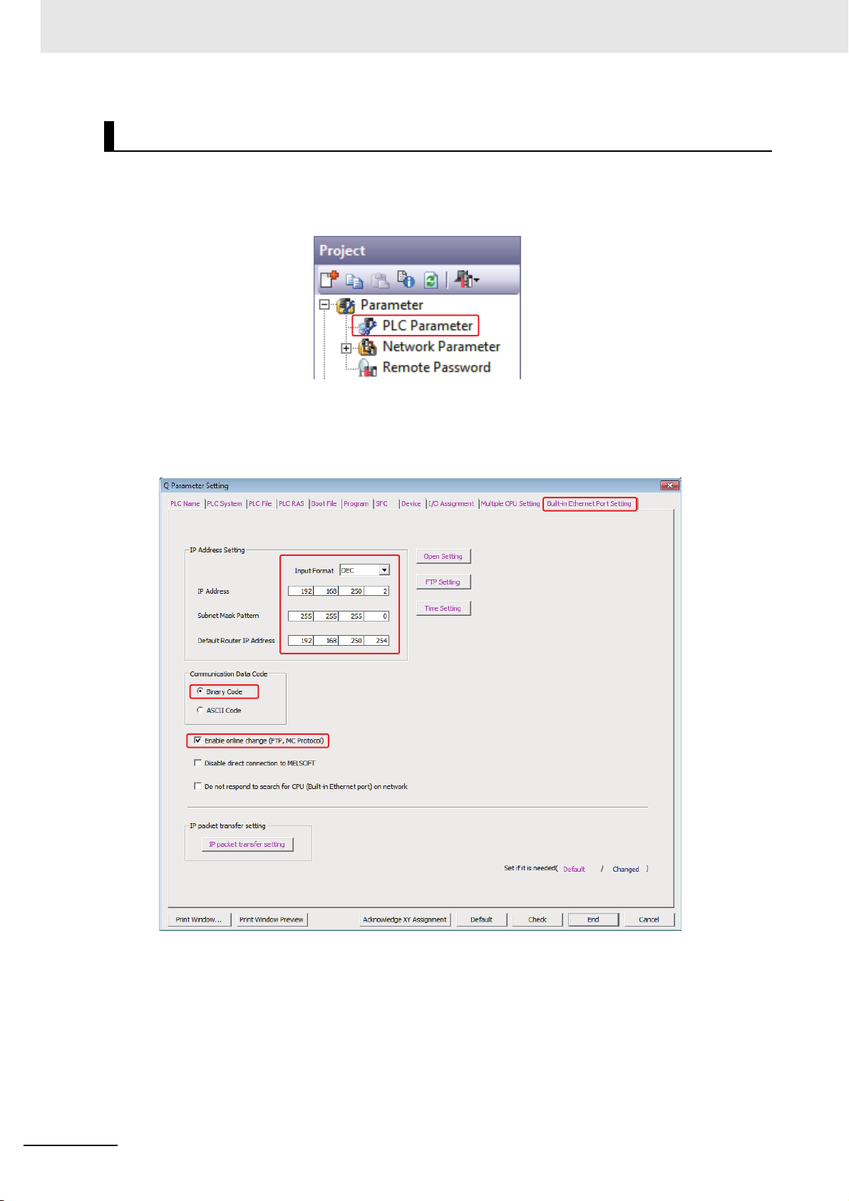
3 Connecting to Mitsubishi PLCs
PLC Settings
The PLC Settings when using Communication Protocol of Mitsubishi QnA 3EBin Ethernet (TCP Slave)
is as shown below.
1
Double-click the [PLC Parameter] under [Project] of GX Works2 software.
2
[Q Parameter Setting] or [L Parameter Setting] dialog boxes are open.
Set the IP address to the same parameters as the PT settings.
Other settings should be the same as the dialog box as below.
3-24
NB-series Programmable Terminals Host Connection Manual (V108)
Page 91
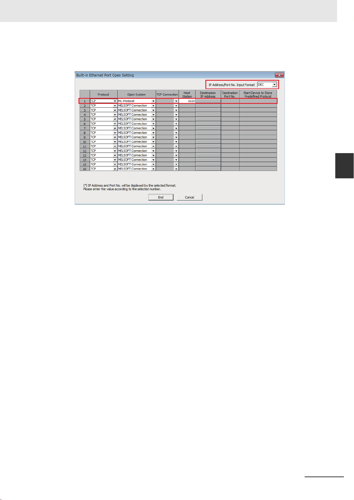
3 Connecting to Mitsubishi PLCs
3
Click the [Open Setting] to open [Build-in Ethernet Port Open Setting] dialog box.
Set the parameters as the same with the dialog box as follows.
3-3 Communication Setting
3
3-3-9 When Using Mitsubishi QnA 3EBin Ethernet (TCP Slave) Communication Protocol
NB-series Programmable Terminals Host Connection Manual (V108)
3-25
Page 92
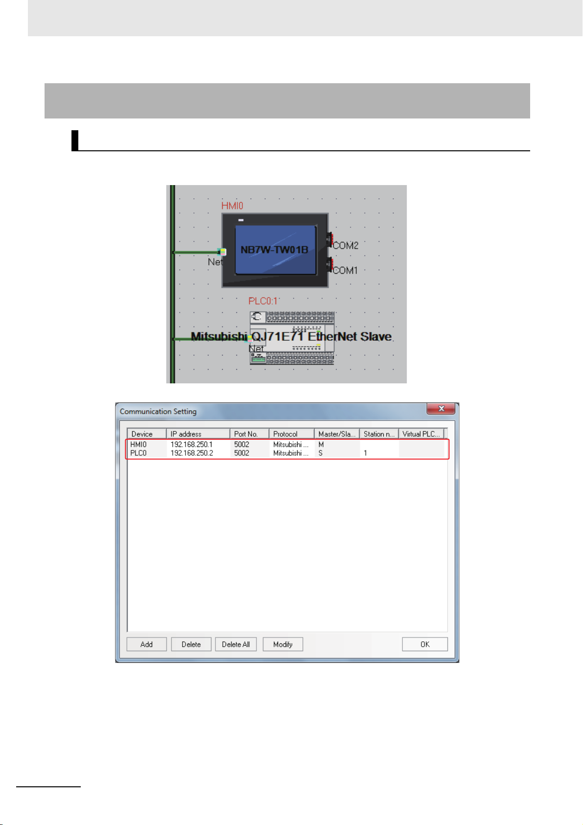
3 Connecting to Mitsubishi PLCs
3-3-10 When Using Mitsubishi QJ71E71 EtherNet Slave Communication
Protocol
PT Settings
The PT Network Settings are as shown below.
3-26
NB-series Programmable Terminals Host Connection Manual (V108)
Page 93

3 Connecting to Mitsubishi PLCs
PLC Settings
PLC Settings when using Mitsubishi QJ71E71 EtherNet Slave Communication Protocol are as shown
below.
1
Double-click the [Ethernet/CC IE/MELSECNET] under [Project] of GX Works2 software.
2
[Network Parameter] tab is opened.
Set the parameters as the same with the diagram as follows.
3-3 Communication Setting
3
3-3-10 When Using Mitsubishi QJ71E71 EtherNet Slave Communication Protocol
Note When connecting to NB, each parameter should be restricted to the ones as follows.
Start I/O No.: 0000
Network No.: 1
Group No.: 0
Station No.: 2 to 64
Mode: Online
NB-series Programmable Terminals Host Connection Manual (V108)
3-27
Page 94

3 Connecting to Mitsubishi PLCs
3
Click the [Operation Setting] to open [Ethernet Operation Setting].
Set the IP address to the same parameters as the PT settings.
Other settings should be the same as the dialog box as below.
4
Click the [Open Setting] to open the [Ethernet Open Setting] tab.
Set the IP address to the same parameters as the PT settings.
Other settings should be the same as the dialog box as below.
3-28
NB-series Programmable Terminals Host Connection Manual (V108)
Page 95
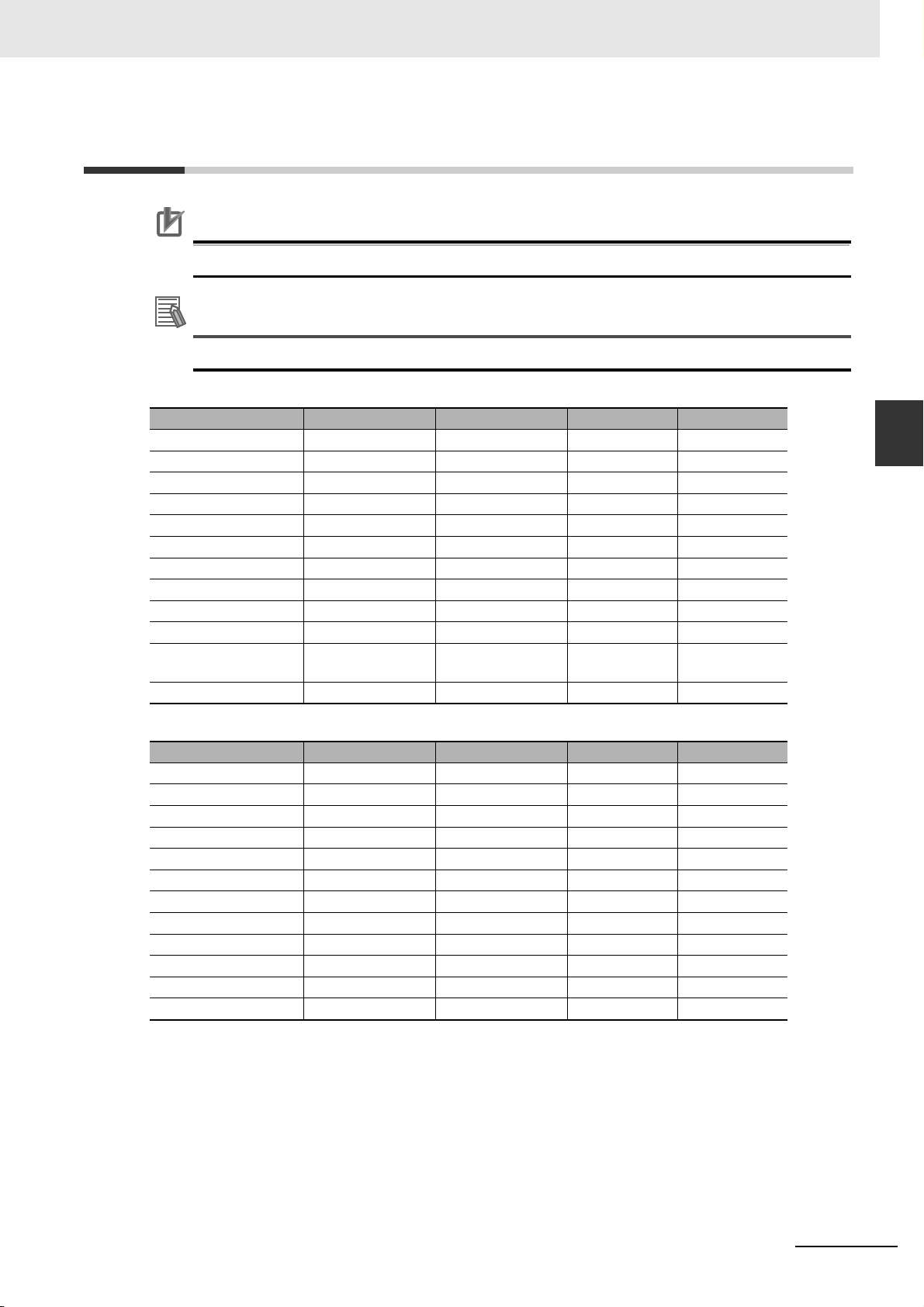
3-4 Supported Registers
Precautions for Correct UsePrecautions for Correct Use
Additional Information
The operation is not guaranteed when the area that does not exist phisically is accessed.
Address format description: D: decimal, O: octal, H: hexadecimal.
Mitsubishi FX1S Driver
Device Bit Address Word Address Format Notes
Input Relay X 0-17 ------ OO
Output Relay Y 0-15 ------ OO
Internal Relay M 0-511 ------ DDD
Timer Contact T 0-63 ------ DD
Counter Contact C 0-31 ------ DD
Data Contact D_bit 0.0-255.F ------ DDD.H
State S 0-127 ------ DDD
Timer Value ------ T_word 0-63 DD
Counter Value ------ C_word 0-31 DD
Data Register ------ D_word 0-255 DDD
Special Data Register ------ SD_word 8000-
8255
Counter Value ------ C_dword 235-255 DDD 32 bit device
3 Connecting to Mitsubishi PLCs
3-4 Supported Registers
3
DDDD
Mitsubishi FX1N/2N/3GS Driver
Device Bit Address Word Address Format Notes
Input Relay X 0-377 ------ OOO
Output Relay Y 0-377 ------ OOO
Internal Relay M 0-3071 ------ DDDD
Timer Contact T_bit 0-255 ------ DDD
Counter Contact C_bit 0-199 ------ DDD
Special Internal Relay SM 8000-8255 ------ DDDD
State S 0-999 ------ DDD
Timer Value ------ T_word 0-255 DDD
Counter Value ------ C_word 0-199 DDD
Data Register ------ D 0-7999 DDDD
Special Data Register ------ SD 8000-8255 DDDD
Counter Value ------ C_dword 200-255 DDD 32 bit device
NB-series Programmable Terminals Host Connection Manual (V108)
3-29
Page 96

3 Connecting to Mitsubishi PLCs
Mitsubishi FX2N-10GM/20GM Driver
Device Bit Address Word Address Format Notes
Input Relay X 0-571 ------ OOO *1
Output Relay Y 0-571 ------ OOO *1
Internal Relay M 0-7999 ------ DDDD *1
Special Internal Relay SM 9000-9999 ------ DDDD *1
Data Register ------ D 0-7999 DDDD *2
Special Data Register ------ SD 9000-9999 DDDD *2
Special Data Register ------ FD 4000-4550 DDDD *2
Present position ------ CP_unit 0-1 D D9004-9005
Present position
(converted into pulses)
*1 does not support batch transmission while
*2 supports batch transmission.
Mitsubishi FX3U Driver
Device Bit Address Word Address Format Notes
Input Relay X 0-764 ------ OOO
Output Relay Y 0-764 ------ OOO
Timer Contact T_bit 0-511 ------ DDD
Counter Contact C_bit 0-255 ------ DDD
Data Contact D_bit 0.0-7999.F ------ DDDD.H
State S 0-4095 ------ DDDD
Internal Relay M 0-7999 ------ DDDD *1
Special Internal Relay SM 8000-9999 ------ DDDD
Timer Value ------ T_word 0-511 DDD
Counter Value ------ C_word 0-199 DDD
Data Register ------ D_word 0-17999 DDDDD
Extension Register ------ R 0-32767 DDDDD
Special Data Register ------ SD 8000-9999 DDDD
Counter Value ------ C_dword 200-255 DDD 32 bit device
*1 The operations accessed beyond the limit is not guaranteed.
------ CP_puls 0-1 D D9074-9075
D9014-9015
D9094-9095
3-30
Mitsubishi FX-485ADP/485BD/232BD (Multi-station) Driver
Device Bit Address Word Address Format Notes
Input Relay X 0-571 ------ OOO
Output Relay Y 0-571 ------ OOO
Timer Contact T_bit 0-511 ------ DDD
Counter Contact C_bit 0-255 ------ DDD
State S 0-4095 ------ DDDD
Internal Relay M 0-7679 ------ DDDD
Special Internal Relay SM 8000-8511 ------ DDDD
Timer Value ------ T_word 0-511 DDD
Counter Value ------ C_word 0-255 DDD
Data Register ------ D 0-7999 DDDD
FIle Register ------ R 0-32767 DDDDD
Special Data Register ------ SD 8000-8511 DDDD
Counter Value ------ C_dword 0-2047 DDDD 32 bit device
NB-series Programmable Terminals Host Connection Manual (V108)
Page 97

3 Connecting to Mitsubishi PLCs
Mitsubishi Q00J (CPU Port) Driver
Device Bit Address Word Address Format Notes
Counter Coil CC 0-1023 DDDD
Counter Contact CS 0-1023 DDDD
Timer Coil TC 0-2047 DDDD
Timer Contact TS 0-2047 DDDD
Special Link Relay SB 0-7FFF ------ HHHH
Link Relay B 0-7FFF ------ HHHH
Step Relay S 0-1FFF ------ HHHH
Edge Relay V 0-32767 ------ DDDDD
Annunciator F 0-32767 ------ DDDDD
Latch Relay L 0-32767 ------ DDDDD
Special Internal Relay SM 0-2047 ------ DDDD
Internal Relay M 0-32767 ------ DDDDD
Output Relay Y 0-1FFF ------ HHHH
Input Relay X 0-1FFF ------ HHHH
File Register ------ R 0-32767 DDDDD
Special Link Register SW 0-7FF HHH
Link Register ------ W 0-291F HHHH
Special Data Register ------ SD 0-2047 DDDD
Data Register ------ D 0-25983 DDDDD
Counter Value ------ CN 0-23087 DDDDD
Retentive Timer Value ------ SN 0-2047 DDDD
Timer Value ------ TN 0-23087 DDDDD
3-4 Supported Registers
3
Mitsubishi Q_QnA (Link Port) Driver
Device Bit Address Word Address Format Notes
Special Link Relay SB 0- 7FFF ------ HHHH
Link Relay B 0- 7FFF ------ HHHH
Step Relay S 0-8191 ------ DDDD
Edge relay V 0-32767 ------ DDDDD
Annunciator F 0-32767 ------ DDDDD
Latch relay L 0-32767 ------ DDDDD
Special Internal Relay SM 0-2047 ------ DDDD
Internal Relay M 0-32767 ------ DDDDD
Output Relay Y 0-1FFF ------ HHHH
Input Relay X 0-1FFF ------ HHHH
Link Register ------ W 0- 291F HHHH
Timer Value ------ TN 0-23087 DDDDD
Counter Value ------ CN 0-23087 DDDDD
Index Register ------ Z 0-19 DD
File Register ------ R 0-32767 DDDDD
Retentive Timer Value ------ SN 0-23087 DDDDD
Special Link Register ------ SW 0- 7FF HHH
File Register
(Block switching is not necessary)
Data Register ------ D 0-25983 DDDDD
Special Data Register ------ SD 0-2047 DDDD
------ ZR 0-65535 DDDDD
NB-series Programmable Terminals Host Connection Manual (V108)
3-31
Page 98

3 Connecting to Mitsubishi PLCs
Mitsubishi Q series (CPU Port) Driver
Device Bit Address Word Address Format Notes
Special Link Relay SB 0-7FFF ------ HHHH
Link Relay B 0-7FFF ------ HHHH
Edge Relay V 0-32767 ------ DDDDD
Annunciator F 0-32767 ------ DDDDD
Latch Relay L 0-32767 ------ DDDDD
Special Internal Relay SM 0-2047 ------ DDDD
Internal Relay M 0-32767 ------ DDDDD
Output Relay Y 0-1FFF ------ HHHH
Input Relay X 0-1FFF ------ HHHH
Step Relay S 0 -8191 ------ DDDD
Link Register ------ W 0-291F HHHH
Timer Value ------ TN 0-23087 DDDDD
Counter Value ------ CN 0-23087 DDDDD
File Register ------ R 0-32767 DDDDD
Special Link Register ------ SW 0-7FF HHH
Data Register ------ D 0-25983 DDDDD
Special Data Register ------ SD 0-2047 DDDD
Index Register ------ Z 0-19 DD
File Register
(Block switching is not
necessary)
Retentive Timer Value ------ SN 0-23087 DDDDD
*1 Supports only Q06UDH.
------ ZR 0-4184063 DDDDDDD *1
Mitsubishi Q06H Driver
Device Bit Address Word Address Format Notes
Special Link Relay SB 0-7FFF ------ HHHH
Link Relay B 0-7FFF ------ HHHH
Edge Relay V 0-32767 ------ DDDDD
Annunciator F 0-32767 ------ DDDDD
Latch Relay L 0-32767 ------ DDDDD
Special Internal Relay SM 0-2047 ------ DDDD
Internal Relay M 0-32767 ------ DDDDD
Output Relay Y 0-1FFF ------ HHHH
Input Relay X 0-1FFF ------ HHHH
Link Register ------ W 0-291F HHHH
Timer Value ------ TN 0-23087 DDDDD
Counter Value ------ CN 0-23087 DDDDD
File Register ------ R 0-32767 DDDDD
Special Link Register ------ SW 0-7FF HHH
Data Register ------ D 0-25983 DDDDD
Special Data Register ------ SD 0-2047 DDDD
3-32
NB-series Programmable Terminals Host Connection Manual (V108)
Page 99
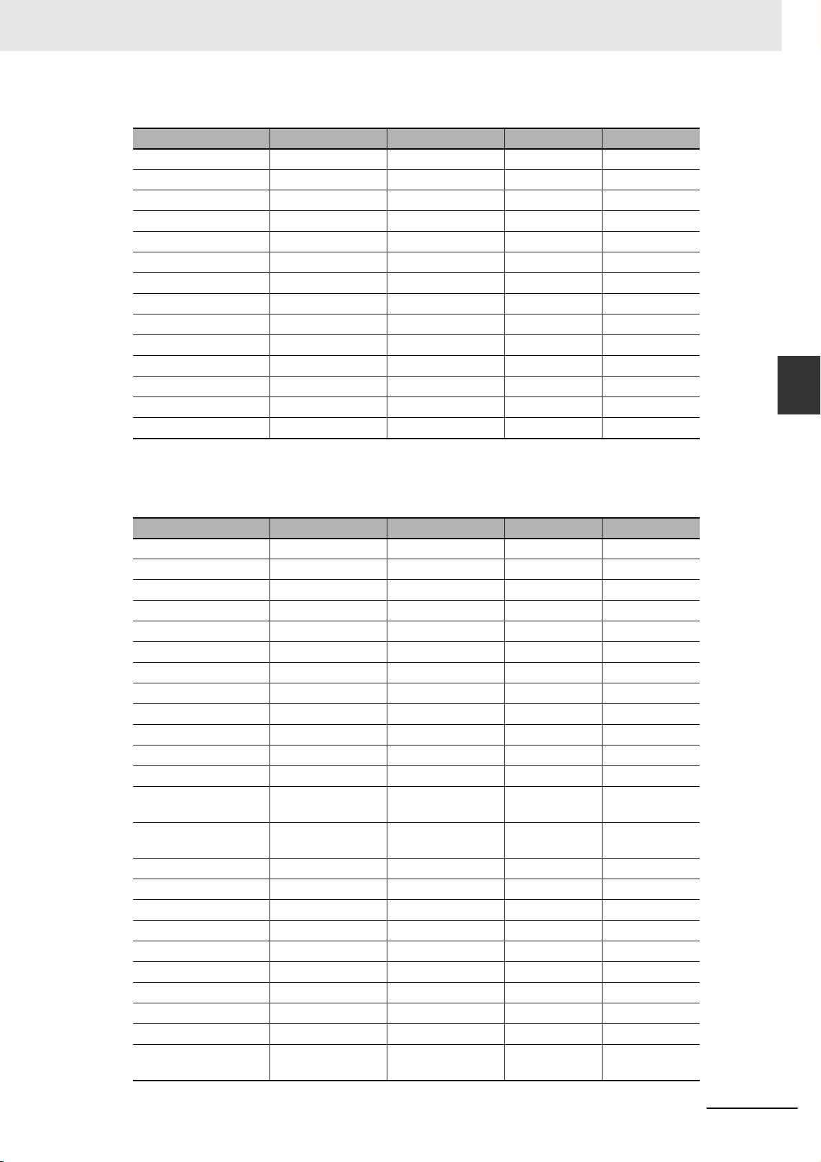
3 Connecting to Mitsubishi PLCs
Mitsubishi FX Series Ethernet (TCP Slave)
Device Bit Address Word Address Format Notes
Input Relay X 0-255 ------ OOO
Output Relay Y 0-255 ------ OOO
Timer Contact T_bit 0-511 ------ DDD
Counter Contact C_bit 0-255 ------ DDD
Data Contact D_bit 0-127999 ------ DDDDD
State S 0-4095 ------ DDDD
Internal Relay M 0-7679 ------ DDDD *1
Special Internal Relay SM 8000-8511 ------ DDDD
Timer Value ------ T_word 0-511 DDD
Counter Value ------ C_word 0-199 DDD
Data Register ------ D_word 0-7999 DDDD
Extension Register ------ R 0000-32767 DDDDD
Special Data Register ------ SD 8000-8511 DDDD
Counter Value ------ C_dword 200-255 DDD 32 bit device
3-4 Supported Registers
3
*1 The operations accessed beyond the limit is not guaranteed.
Mitsubishi QnA 3EBin Ethernet (TCP Slave) Driver
Device Bit Address Word Address Format Notes
Input Relay X 0-3FFF ------ HHHH
Output Relay Y 0-3FFF ------ HHHH
Direct Input DX 0- 1FFF ------ HHHH
Direct Output DY 0- 1FFF ------ HHHH
Internal Relay M 0-61439 ------ DDDDD
Special Internal Relay SM 0-2255 ------ DDDD
Latch Relay L 0-32767 ------ DDDDD
Annunciator F 0-32767 ------ DDDDD
Edge Relay V 0-2047 ------ DDDDD
Link Relay B 0- EFFF ------ HHHH
Timer Contact TS 0-32767 ------ DDDDD
Timer Coil TC 0-32767 ------ DDDDD
Accumulated Timer
(contact)
Accumulated Timer
(coil)
Counter Contact CS 0-32767 ------ DDDDD
Counter Coil CC 0-32767 ------ DDDDD
Special Link Relay SB 0-7FFF ------ HHHH
Step Relay S 0-32767 ------ DDDDD
Data Register ------ D 0-61439 DDDDD
Special Data Register ------ SD 0-2255 DDDD
Link Register ------ W 0- EFFF HHHH
Special Link Register ------ SW 0-7FFF HHHH
Timer Value ------ TN 0-32767 DDDDD
Accumulated Timer
(present value (PV))
SS 0-32767 ------ DDDDD
SC 0-32767 ------ DDDDD
------ SN 0-32767 DDDDD
NB-series Programmable Terminals Host Connection Manual (V108)
3-33
Page 100

3 Connecting to Mitsubishi PLCs
Device Bit Address Word Address Format Notes
Counter Value ------ CN 0-32767 DDDDD
Index Register ------ Z 0-19 DD
File Register ------ R 0-32767 DDDDD
File Register
(Block switching is not
necessary)
Special Link Resister ------ SB 0-7FF0 HHHH
Link Resister ------ B 0-EFF0 HHHH
Input ------ X 0-3FF0 HHHH
Output ------ Y 0-3FF0 HHHH
Mitsubishi QJ71E71 Ethernet (TCP Slave) Driver
Device Bit Address Word Address Format Notes
Input Relay X 0-2000 ------ HHHH
Output Relay Y 0-2000 ------ HHHH
Internal Relay M 0-32768 ------ DDDDD
Special Internal Relay SM 0-2048 ------ DDDD
Latch Relay L 0-32768 ------ DDDDD
Annunciator F 0-32768 ------ DDDDD
Edge Relay V 0-32768 ------ DDDDD
Link Relay B 0-8000 ------ HHHH
Timer Contact TS 0-23088 ------ DDDDD
Timer Coil TC 0-23088 ------ DDDDD
Accumulated Timer
(contact)
Accumulated Timer
(coil)
Counter Contact CS 0-23088 ------ DDDDD
Counter Coil CC 0-23088 ------ DDDDD
Special Link Relay SB 0-8000 ------ HHHH
Step Relay S 0-8192 ------ DDDD
Data Register ------ D 0-25984 DDDDD
Special Data Register ------ SD 0-2048 DDDD
Link Register ------ W 0- 2920 HHHH
Special Link Register ------ SW 0-800 HHH
Timer Value ------ TN 0-23088 DDDDD
Accumulated Timer
(present value (PV))
Counter Value ------ CN 0-23088 DDDDD
File Register ------ R 0-32768 DDDDD
File Register
(Block switching is not
necessary)
------ ZR 0-4849663 DDDDDDD
SS 0-23088 ------ DDDDD
SC 0-23088 ------ DDDDD
------ SN 0-23088 DDDDD
------ ZR 0-1042432 DDDDDDD
3-34
NB-series Programmable Terminals Host Connection Manual (V108)
 Loading...