

Page 1
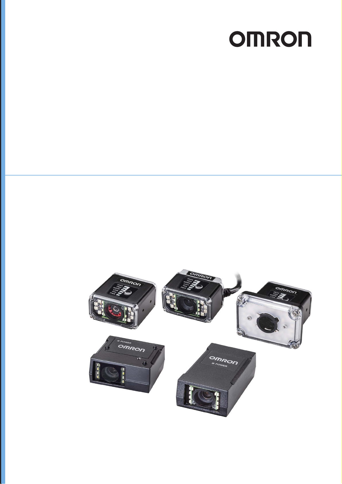
MicroHAWK V320-F / V330-F / V420-F / V430-F
Barcode Reader
User Manual
Z432-E-02 (84-9000400-02)
Page 2

NOTE
• All rights reserved.
• No part of this publication may be reproduced, stored in a retrieval system, or transmitted, in any
form, or by any means, mechanical, electronic, photocopying, recording, or otherwise, without the
prior written permission of OMRON.
• No patent liability is assumed with respect to the use of the information contained herein. Moreover,
because OMRON is constantly striving to improve its high-quality products, the information con-
tained in this manual is subject to change without notice. Every precaution has been taken in the
preparation of this manual. Nevertheless, OMRON assumes no responsibility for errors or omis-
sions.
Neither is any liability assumed for damages resulting from the use of the information contained in
this publication.
Trademarks
• Sysmac and SYSMAC are trademarks or registered trademarks of OMRON Corporation in Japan
and other countries for OMRON factory automation products.
• Microsoft, Windows, Windows Vista, Excel, and Visual Basic are either registered trademarks or
trademarks of Microsoft Corporation in the United States and other countries.
• ODVA, CIP, CompoNet, DeviceNet, and EtherNet/IP are trademarks of ODVA.
• QR Code is a registered trademark of DENSO WAVE INCORPORATED.
Other company names and product names in this document are the trademarks or registered trade-
marks of their respective companies.
Copyrights
Microsoft product screen shots reprinted with permission from Microsoft Corporation.
Page 3

Terms and Conditions Agreement
Terms and Conditions Agreement
Warranty, Limitations of Liability
Warranties
Exclusive Warranty
Omron’s exclusive warranty is that the Products will be free from defects in materials and
workmanship for a period of twelve months from the date of sale by Omron (or such other period
expressed in writing by Omron). Omron disclaims all other warranties, express or implied.
Limitations
OMRON MAKES NO WARRANTY OR REPRESENTATION, EXPRESS OR IMPLIED, ABOUT
NON-INFRINGEMENT, MERCHANTABILITY OR FITNESS FOR A PARTICULAR PURPOSE OF
THE PRODUCTS. BUYER ACKNOWLEDGES THAT IT ALONE HAS DETERMINED THAT THE
PRODUCTS WILL SUITABLY MEET THE REQUIREMENTS OF THEIR INTENDED USE.
Omron further disclaims all warranties and responsibility of any type for claims or expenses base
on infringement by the Products or otherwise of any intellectual property right.
d
Buyer Remedy
Omron’s sole obligation hereunder shall be, at Omron’s election, to (i) replace (in the form originally
shipped with Buyer responsible for labor charges for removal or replacement thereof) the
non-complying Product, (ii) repair the non-complying Product, or (iii) repay or credit Buyer an
amount equal to the purchase price of the non-complying Product; provided that in no event sh
Omron be responsible for warranty, repair, indemnity or any other claims or expenses regarding the
Products unless Omron’s analysis confirms that the Products were properly handled, stored,
installed and maintained and not subject to contamination, abuse, misuse or inappropriate
modification. Return of any Products by Buyer must be approved in writing by Omron before
shipment. Omron Companies shall not be liable for the suitability or unsuitability or the resu
the use of Products in combination with any electrical or electronic components, circuits, system
assemblies or any other materials or substances or environments. Any advice, recommendations or
information given orally or in writing, are not to be construed as an amendment or addition to the
above warranty.
See http://www.omron.com/global/ or contact your Omron representative for published information.
Limitation on Liability; Etc
OMRON COMPANIES SHALL NOT BE LIABLE FOR SPECIAL, INDIRECT, INCIDENTAL, OR
CONSEQUENTIAL DAMAGES, LOSS OF PROFITS OR PRODUCTION OR COMMERCIAL LOSS
IN ANY WAY CONNECTED WITH THE PRODUCTS, WHETHER SUCH CLAIM IS BASED IN
CONTRACT, WARRANTY, NEGLIGENCE OR STRICT LIABILITY.
all
lts from
Further, in no event shall liability of Omron Companies exceed the individual price of the Product on
which liability is asserted.
MicroHAWK V320-F / V330-F / V420-F / V430-F Barcode Reader User Manual
3
Page 4

Terms and Conditions Agreement
Application Considerations
Suitability of Use
Omron Companies shall not be responsible for conformity with any standards, codes or regulations
which apply to the combination of the Product in the Buyer’s application or use of the Product. At
Buyer’s request, Omron will provide applicable third party certification documents identifying ratings
and limitations of use which apply to the Product. This information by itself is not sufficient for
complete determination of the suitability of the Product in combination with the end product,
machine, system, or other application or use. Buyer shall be solely responsible for determining
appropriateness of the particular Product with respect to Buyer’s application, product or system.
Buyer shall take application responsibility in all cases.
NEVER USE THE PRODUCT FOR AN APPLICATION INVOLVING SERIOUS RISK TO LIFE OR
PROPERTY OR IN LARGE QUANTITIES WITHOUT ENSURING THAT THE SYSTEM AS A
WHOLE HAS BEEN DESIGNED TO ADDRESS THE RISKS, AND THAT THE OMRON
PRODUCT(S) IS PROPERLY RATED AND INSTALLED FOR THE INTENDED USE WITHIN THE
OVERALL EQUIPMENT OR SYSTEM.
a
Programmable Products
Omron Companies shall not be responsible for the user’s programming of a programmable Product,
or any consequence thereof.
Disclaimers
Performance Data
Data presented in Omron Company websites, catalogs and other materials is provided as a guide
for the user in determining suitability and does not constitute a warranty. It may represent the result
of Omron’s test conditions, and the user must correlate it to actual application requirements. Actual
performance is subject to the Omron’s Warranty and Limitations of Liability.
Change in Specifications
Product specifications and accessories may be changed at any time based on improvements and
other reasons. It is our practice to change part numbers when published ratings or features are
changed, or when significant construction changes are made. However, some specifications of the
Product may be changed without any notice. When in doubt, special part numbers may be assigned
to fix or establish key specifications for your application. Please consult with your Omron’s
representative at any time to confirm actual specifications of purchased Product.
Errors and Omissions
Information presented by Omron Companies has been checked and is believed to be accurate;
however, no responsibility is assumed for clerical, typographical or proofreading errors or omissions.
4
MicroHAWK V320-F / V330-F / V420-F / V430-F Barcode Reader User Manual
Page 5
Safety Precautions
CAUTION
Symbols and the meanings for safety precautions described in this manual.
In order for the product to be used safely, the following indications are used in this book to draw your
attention to the cautions. The cautions with the indications describe the important contents for
safety.
Indicates a potentially hazardous situation which, if not avoided, will result in minor or moderate
WARNING
Meanings of Alert Symbols
injury, or may result in serious injury or death.
Additionally there may be significant property damage.
Indicates a potentially hazardous situation which, if not avoided, may result in minor or moderate
injury or in property damage.
Safety Precautions
General Prohibition
Indicates general prohibitions, including warnings, for which there is no specific symbol.
General Caution
Indicates general cautions, including warnings, for which there is no specific symbol.
Electrical Hazard
Indicates the possible danger of electric shock under specific conditions.
High Temperature Caution
Indicates the possible danger of injury by high temperature under specific conditions.
MicroHAWK V320-F / V330-F / V420-F / V430-F Barcode Reader User Manual
5
Page 6
WARNING
Safety Precautions
Alert statements in this Manual
This product must be used according to this manual or Instruction sheet.
Failure to observe this may result in impairment of functions and performance of the product.
This product is not designed or rated for ensuring safety of persons. Do not use it for such purposes.
Never connect the AC power supply with this product.
When the AC power supply is connected, it causes the electric shock and a fire.
When using equipment that is connected to an AC power source such as an AC adapter or PoE
injector, use it within the rated voltage range. Usage with a voltage higher than what it is rated for
may cause serious personal injury due to electric shock, or serious physical damage due to fire or
equipment failure. Do not touch any part
OFF the power.
of the device while in operation, or immediately after turning
Since camera that can be connected with this product emits a visible light that may have an adverse
effect on the eyes, do not stare directly into the light emitted from the LED. If a specular object is
used, take care not to allow reflected light enter your eyes.
Please take external safety measures so that the system as a whole should be on the safe side even
if a failure of a this product or an error due to an external factor occurred. An abnormal operation may
result in serious accident.
Please take fail-safe measures on your side in preparation for an abnormal signal due to signal
conductor disconnection and/or momentary power interruption. An abnormal operation may result in
a serious accident.
CAUTION
Danger of burns. Do not touch the case while the reader is running or just after power is turned OFF,
since it remains extremely hot.
6
MicroHAWK V320-F / V330-F / V420-F / V430-F Barcode Reader User Manual
Page 7

Precautions for Safe Use
Condition of the fitness of OMRON products
• Please do not use this product to directly or indirectly use to detect the human body for the purpose
of ensuring the safety. In the same application, please use the safety sensor that is published on our
sensor catalog.
• Omron products are designed and manufactured as general-purpose products for use in general
industrial applications. They are not intended to be used in the following critical applications. If you
are using Omron products in the following applications, Omron shall not provide any warranty for
such Omron products, unless otherwise specifically agreed or unless the specific applications are
intended by Omron.
(a) Applications with stringent safety requirements, including but not limited to nuclear power control
equipment, combustion equipment, aerospace equipment, railway equipment, elevator/lift
equipment, amusement park equipment, medical equipment, safety devices and other applications
that could cause danger/harm to people’s body and life
(b) Applications that require high reliability, including but not limited to supply systems for gas, water
and electricity, etc., 24 hour continuous operating systems, financial settlement systems and other
applications that handle rights and property
(c) Applications under severe condition or in severe environment, including but not limited to outdoor
equipment, equipment exposed to chemical contamination, equipment exposed to electromagnetic
interference and equipment exposed to vibration and shocks
(d) Applications under conditions and environment not described in specifications
*1. In addition to the applications listed from (a) to (d) above, Omron products (see definition) are not intended for
use in vehicles designed human transport (including two wheel vehicles). Please do NOT use Omron
products for vehicles designed human transport. Please contact the Omron sales staff for information on our
automotive line of products.
*2. The above is part of the Terms and Conditions Agreement. Please use carefully read the contents of the
guarantee and disclaimers described in our latest version of the catalog, data sheets and manuals.
Precautions for Safe Use
Installation Environment
• Do not use the product in areas where flammable or explosive gases are present.
• Be careful when unpacking this product, please. Injury may occur if the reader falls and strikes a
person.
• Do not install the product close to high-voltage devices and power devices in order to secure the
safety of operation and maintenance.
• Make sure to tighten all installation screws securely.
MicroHAWK V320-F / V330-F / V420-F / V430-F Barcode Reader User Manual
7
Page 8

Precautions for Safe Use
Power Supply and Wiring
• Make sure to use the product with the power supply voltage specified by this manual.
• Do not connect AC power source to Sensor Controller. If connects AC power source, it might be a
cause of the failure.
• Use the wire of a suitable size (AWG 16 to 12) acco
• Use a DC power supply with safety measures against high-voltage spikes (safety extra low-voltage
circuits on the secondary side).
• Keep the power supply wires as short as possible.
• Do the following confirmations again before turning on the power supply.
• Is the voltage and polarity of the power supply correct?
• Is not the load of the output signal short-circuited?
• Is the load current of the output signal appropriate?
• Is not the mistake found in wiring?
Ground
rding to the current consumption.
• Check wiring again before turning on the reader.
Other
• Use only the cables designed specifically for the reader. Use of other products may result
malfunction or damage of the reader.
• Always turn OFF the power of the reader and peripheral devices before connecting or disconnecting
a cable. Connecting the cable with power supplied may result in damage of the reader or peripheral
devices.
• Do not apply torsion stress to the cable. It may damage the cable.
• Secure the minimum bending radius of the cable. Otherwise the cable may be damaged.
• Do not attempt to dismantle, repair, or modify the product.
• Should you notice any abnormalities, immediately stop use, turn OFF the power supply, and contact
your OMRON representative.
• While the power is ON or immediately after the power is turned OFF, the case are still hot. Do not
touch the case.
• The reader must be used with the special mounting bracket (-AM0 or -AM1: sold separately), or the
reader may generate heat.
• When disposing of the product, treat it as an industrial waste.
• Do not drop the product nor apply excessive vibration or shock to the product. Doing so may cause
malfunction or burning.
• When controlling stages and robots using the read results (axis movement output based on
calibration and alignment measurement), always take fail-safe measures within the stage and robot
systems, such as checking whether the data obtained from the read results is within the range of
movement of the stages and robots.
in
8
MicroHAWK V320-F / V330-F / V420-F / V430-F Barcode Reader User Manual
Page 9

Precautions for Correct Use
Installation and Storage Sites
Install and store the product in a location that meets the following conditions:
• Surrounding temperature of 0 to +40°C (-50 to +75°C in storage)
• No rapid changes in temperature (place where dew does not form)
• Relative humidity of between 5 to 85%
• No presence of corrosive or flammable gases
• Place free of dust, salts and iron particles
• Place free of vibration and shock
• Place out of direct sunlight
• Place where it will not come into contact with water, oils or chemicals
• Place not affected by strong electro-magnetic waves
• Place not near to high-voltage, or high-power equipment
Precautions for Correct Use
Ambient Temperature
• For good heat dissipation, keep the distance.
• Do not install the product immediately above significant heat sources, such as heaters, transformers,
or large-capacity resistors.
• Do not let the ambient temperature exceed an operating temperature range.
• Provide a forced-air fan cooling or air conditioning if the ambient temperature is near the upper range
of operating temperature range so that the ambient temperature never exceeds the upper range of
operating temperature range.
Noise Resistance
• Do not install the product in a cabinet containing high-voltage equipment.
• Do not install the reader within 200 mm of power cables.
MicroHAWK V320-F / V330-F / V420-F / V430-F Barcode Reader User Manual
9
Page 10

Precautions for Correct Use
Component Installation and Handling
• Turning OFF the Power
When a message is displayed indicating that a task is in progress, do not turn OFF the power. Doing
so causes the data in the memory to be corrupted, resulting in the product not operating properly
upon the next start-up.
When turns OFF, conform the followings proceedings have completed. and then operate again.
• When saves using the reader:
Confirm the save processing is completed and next operation is possible.
• When saves using communication command:
Intended command is completed.
• Setting of Power Source
The power source need to be supplied from DC power source apparatus which is taken a save
ultra-low voltage circuit: to protect high voltage.
Maintenance
• Turn OFF the power and ensure the safety before maintenance.
• Clean the lens with a lens-cleaning cloth or air brush.
• Lightly wipe off dirt with a soft cloth.
• Do not use thinners or benzene.
• To ensure safe access for operation and maintenance, separate the reader as much as possible from
high-voltage equipment and power machinery.
Communication with High-Order Device
• After confirming that this product is started up, communicate with the high-order device. Wh
product has started up, an indefinite signal may be output from the high-order interface. To avoid this
problem, clear the receiving buffer of your device at initial operations.
en this
Other
• For symbols with a highly gloss surface, reading errors may occur because of regular reflection of the
LED light. If this occurs, provide a skew angle of 15° against the symbol.
• Do not look into the light emitted from the LED directly. When this products has started up, the LED
flashes.
• Under an environment with high humidity and rapid changes in temperature, the inside of the front
plate might fog up. When the read rates lower due to the fog, leave the device with turned it on for 30
minutes to 2 hours. Use it again after checking there is no fog on the front plate.
10
LED Safety
• This product is classified into the IEC 62471-1:2006 Risk-Exempt Group. However, this product does
emit a strong visible light that may have an adverse effect on the eyes. Do not stare directly into the
lig
ht emitted from the LED. If a specular object is used, take care not to allow reflected light to enter
your eyes.
MicroHAWK V320-F / V330-F / V420-F / V430-F Barcode Reader User Manual
Page 11
Regulations and Standards
Using Product Outside Japan
This regulation applies to MicroHAWK readers and peripheral devices.
If you export (or provide a non-resident with) this product or a part of this product that falls under the
category of goods (or technologies) specified by the Foreign Exchange and Foreign Trade Control Law
as those which require permission or approval for export, you must obtain permission or approval or
service transaction permission) pursuant to the law.
Conformance to EC/EU Directives
This regulation applies to MicroHAWK code readers and peripheral devices.
• This product is in compliance with all applicable directives, 2014/30/EU, 2014/35/EU, and 2011/65/EU.
• This product complies with EC/EU Directives. EMC-related performance of the OMRON devices th
comply with EC/EU Directives will vary depending on the configuration, wiring, and other conditions
of the equipment or control panel on which the OMRON devices are installed.
• The customer must, therefore, perform the final check to confirm that devices and the overall
machine conform to EMC standards.
Regulations and Standards
at
Conformance to UL Standards
This regulation applies to reader and peripheral devices.
This product complies with UL Standards.
nd
• UL60950-1 2
-edition, 2014 (Class III)
Korean Radio Regulation (KC)
Guide for Users
This equipment has been evaluated for conformity in a commercial environment. When used in a residential
environment, it may cause radio interference.
MicroHAWK V320-F / V330-F / V420-F / V430-F Barcode Reader User Manual
11
Page 12

Regulations and Standards
Radio Frequency Interference Requirements: FCC
This equipment h
and has been found to conform to applicable FCC standards. To comply with FCC RF exposure compliance
requirements, this device must not be co-located with or operate in conjunction with any other antenna or transmitter.
Changes or modifications not expressly approved by the party responsible for compliance could void the user’s
authority to operate the equipment.
as been tested for compliance with FCC (Federal Communications Commission) requirements
Model V420-F Class A Statement
NOTE: This equipment has been tested and found to comply with the limits for a Class A digital device, pursuant
to part 15 of the FCC Rules. These limits are designed to provide reasonable protection against harmful interference
when the equipment is operated in a commercial environment. This equipment generates, uses, and can radiate
radio frequency energy and, if not installed and used in accordance with the instruction manual, may cause
harmful interference to radio communications. Operation of this equipment in a residential area is likely to cause
harmful interference in which case the user will be required to correct the interference at his own expense.
Models V320-F, V330-F, and V430-F Class B Statement
NOTE: This equipment has been tested and found to comply with the limits for a Class B digital device, pursuant
to part 15 of the FCC Rules. These limits are designed to provide reasonable protection against harmful interference
in a residential installation. This equipment generates, uses and can radiate radio frequency energy and, if not
installed and used in accordance with the instructions, may cause harmful interference to radio communications.
However, there is no guarantee that interference will not occur in a particular installation. If this equipment does
cause harmful interference to radio or television reception, which can be determined by turning the equipment off
and on, the user is encouraged to try to correct the interference by one or more of the following measures:
• Reorient or relocate the receiving antenna
• Increase the separation between the equipment and receiver.
• Connect the equipment into an outlet on a circuit different from that to which the receiver is connected.
• Consult the dealer or an experienced radio/TV technician for help.
.
Radio Frequency Interference Requirements: Canada
This device complies with Industry Canada ICES-003. Operation is subject to the following two conditions: (1)
This device may not cause harmful interference, and (2) this device must accept any interference received,
including interference that may cause undesired operation. Cet appareil est conforme à la norme ICES-003
d'Industrie Canada. Son fonctionnement est soumis aux deux conditions suivantes: (1) l’appareil ne doit pas
produire de brouillage, et (2) l’utilisateur de l’appareil doit accepter tout brouillage radioélectrique subi, même si
le brouillage est susceptible d’en compromettre le fonctionnement.
Model V420-F: This Class A digital apparatus complies with Canadian ICES-003.
Cet appareil numérique de la classe A est conforme à la norme NMB-003 du Canada.
Models V320-F, V330-F and V430-F : This Class B digital apparatus complies with Canadian ICES-003. Cet
appareil numérique de la classe B est conforme à la norme NMB-003 du Canada.
12
MicroHAWK V320-F / V330-F / V420-F / V430-F Barcode Reader User Manual
Page 13
Revision History
The manual’s part number and revision letter appear on the first and last pages.
Z432-E-02
Revision Date Revised content
01
02 January 2020 Updated front window, diffuser, and polarizer accessory part numbers.
November 2019 First Publication.
Revision History
Revision
MicroHAWK V320-F / V330-F / V420-F / V430-F Barcode Reader User Manual
13
Page 14

CONTENTS
Table of Contents
Terms and Conditions Agreement ..........................................................................3
Safety Precautions ...................................................................................................5
Precautions for Safe Use.........................................................................................7
Precautions for Correct Use....................................................................................9
Regulations and Standards...................................................................................11
Revision History .....................................................................................................12
Section 1 Overview
1-1 Introduction............................................................................................................................... 1-2
1-2 Splash Screen........................................................................................................................... 1-3
1-3 Navigation Bar .......................................................................................................................... 1-4
1-4 Flash Icon.................................................................................................................................. 1-5
1-5 Help Icon ................................................................................................................................... 1-6
1-6 Application Settings Icon......................................................................................................... 1-7
1-7 Left Panel .................................................................................................................................. 1-8
1-8 Right Panel.............................................................................................................................. 1-10
1-9 Image Area .............................................................................................................................. 1-11
1-10 Guided Tour .......................................................................................................................... 1-16
Section 2 Quick Start
2-1 Introduction .............................................................................................................................. 2-2
2 MicroHAWK and WebLink Quick Start.................................................................................... 2-2
2-
Section 3 Start
3-1 Overview.................................................................................................................................... 3-2
3-2 Assisted Setup.......................................................................................................................... 3-4
3-3 Reader Information................................................................................................................... 3-5
3-4 Setup Buttons ........................................................................................................................... 3-6
Section 4 Setup
4-1 Cycle .......................................................................................................................................... 4-2
4-2 Acquire ...................................................................................................................................... 4-4
4-3 Decode....................................................................................................................................... 4-7
4-4 Match String.............................................................................................................................. 4-9
14
MicroHAWK V320-F / V330-F / V420-F / V430-F Barcode Reader User Manual
Page 15

4-5 Format Output......................................................................................................................... 4-13
4-6 Outputs.................................................................................................................................... 4-17
4-7 Configuration Database ......................................................................................................... 4-19
4-8 Favorites.................................................................................................................................. 4-25
Section 5 Run
5-1 Counts ....................................................................................................................................... 5-2
5-2 Rate............................................................................................................................................ 5-3
5-3 Read Time ................................................................................................................................. 5-4
5-4 Output Data ............................................................................................................................... 5-5
5-5 Image History............................................................................................................................ 5-6
Section 6 Application Settings
CONTENTS
6-1 Application Settings Menu....................................................................................................... 6-2
6-2 Save ........................................................................................................................................... 6-3
6-3 New ............................................................................................................................................ 6-4
6-4 Load ........................................................................................................................................... 6-5
6-5 Advanced .................................................................................................................................. 6-6
6-6 Language................................................................................................................................... 6-7
6-7 Terminal..................................................................................................................................... 6-8
6-8 Beeper ....................................................................................................................................... 6-9
6-9 Guided Tour ............................................................................................................................ 6-10
6-10 Image Storage....................................................................................................................... 6-11
6-11 Restore Default Settings...................................................................................................... 6-18
6-12 Activate Account Management ........................................................................................... 6-19
6-13 Enable USB Drive Mode....................................................................................................... 6-27
6-14 About WebLink ..................................................................................................................... 6-28
Section 7 Terminal
7-1 Send........................................................................................................................................... 7-2
7-2 Find ............................................................................................................................................ 7-3
7-3 Filters......................................................................................................................................... 7-4
Section 8 Advanced Settings
8-1 Introduction............................................................................................................................... 8-2
8-2 Camera Setup ........................................................................................................................... 8-3
8-3 Communications ...................................................................................................................... 8-4
8-4 Read Cycle ................................................................................................................................ 8-5
8-5 Symbologies ............................................................................................................................. 8-6
MicroHAWK V320-F / V330-F / V420-F / V430-F Barcode Reader User Manual
15
Page 16

CONTENTS
8-6 I/O............................................................................................................................................... 8-8
8-7 Symbol Quality ....................................................................................................................... 8-25
8-8 Match String............................................................................................................................ 8-26
8-9 Diagnostics ............................................................................................................................. 8-27
8-10 Image Storage....................................................................................................................... 8-28
8-11 Configuration Database ....................................................................................................... 8-29
8-12 Differences from Default...................................................................................................... 8-30
Appendices
Appendix A General Specifications ..............................................................................................A-1
Appendix B Electrical Specifications ...........................................................................................B-1
Appendix C Serial Commands ......................................................................................................C-1
Appendix D Communications........................................................................................................D-1
Appendix E Calibration .................................................................................................................. E-1
Appendix F Read Cycle.................................................................................................................. F-1
Appendix G Symbologies ............................................................................................................. G-1
Appendix H I/O Parameters ...........................................................................................................H-1
Appendix I Symbol Quality ............................................................................................................. I-1
Appendix J Matchcode................................................................................................................... J-1
Appendix K Camera and IP Setup.................................................................................................K-1
Appendix L Configuration Database............................................................................................. L-1
Appendix M Utilities ...................................................................................................................... M-1
Appendix N Output Format............................................................................................................N-1
Appendix O Communications Protocol....................................................................................... O-1
Appendix P ASCII Table .................................................................................................................P-1
Appendix Q Glossary of Terms ....................................................................................................Q-1
Appendix R Q & A...........................................................................................................................R-1
16
MicroHAWK V320-F / V330-F / V420-F / V430-F Barcode Reader User Manual
Page 17

Overview
This section provides a general overview of the WebLink user interface.
1-1 Introduction . . . . . . . . . . . . . . . . . . . . . . . . . . . . . . . . . . . . . . . . . . . . . . . . . . 1-2
1-2 Splash Screen . . . . . . . . . . . . . . . . . . . . . . . . . . . . . . . . . . . . . . . . . . . . . . . . 1-3
1-3 Navigation Bar . . . . . . . . . . . . . . . . . . . . . . . . . . . . . . . . . . . . . . . . . . . . . . . . 1-4
1-4 Flash Icon . . . . . . . . . . . . . . . . . . . . . . . . . . . . . . . . . . . . . . . . . . . . . . . . . . . . 1-5
1-5 Help Icon . . . . . . . . . . . . . . . . . . . . . . . . . . . . . . . . . . . . . . . . . . . . . . . . . . . . 1-6
1-6 Application Settings Icon . . . . . . . . . . . . . . . . . . . . . . . . . . . . . . . . . . . . . . . 1-7
1-7 Left Panel . . . . . . . . . . . . . . . . . . . . . . . . . . . . . . . . . . . . . . . . . . . . . . . . . . . . 1-8
1-8 Right Panel . . . . . . . . . . . . . . . . . . . . . . . . . . . . . . . . . . . . . . . . . . . . . . . . . . 1-10
1-9 Image Area . . . . . . . . . . . . . . . . . . . . . . . . . . . . . . . . . . . . . . . . . . . . . . . . . . 1-11
1-10 Guided Tour . . . . . . . . . . . . . . . . . . . . . . . . . . . . . . . . . . . . . . . . . . . . . . . . . 1-16
1
MicroHAWK V320-F / V330-F / V420-F / V430-F Barcode Reader User Manual
1-1
Page 18

1 Overview
1-1 Introduction
The browser-based WebLink interface enables quick and easy configuration and testing of
MicroHAWK V320-F, V330-F, V420-F, V430-F readers without the need to install or access files on a
host system.
WebLink is reliable, lightweight, and operating-system-independent without compromising the power
and depth of its tool set.
WebLink offers novice users an intuitive way to connect, configure, monitor, and troubleshoot a
MicroHAWK reader, and provides the power and flexibility expected by advanced users.
1-2
MicroHAWK V320-F / V330-F / V420-F / V430-F Barcode Reader User Manual
Page 19

1 Overview
1-2 Splash Screen
After you open a browser and
screen
, a portion of which is shown below. You will also see a progress bar as your WebLink session starts.
enter your reader's IP address
, the first thing you will see is the
1-2 Splash Screen
splash
1
MicroHAWK V320-F / V330-F / V420-F / V430-F Barcode Reader User Manual
1-3
Page 20

1 Overview
1-3 Navigation Bar
The navigation bar at the top of the WebLink interface features buttons for three primary views: Start,
Setup, and Run.
1-4
MicroHAWK V320-F / V330-F / V420-F / V430-F Barcode Reader User Manual
Page 21
1 Overview
1-4 Flash Icon
The flash icon allows you to save current settings to the reader for reboot. When the current reader
settings match those saved in flash memory, the disk icon changes from red to blue.
1-4-1 Save to Flash Memory
1-4-2 Saved to Flash Memory
1-4 Flash Icon
1
1-4-1 Save to Flash Memory
MicroHAWK V320-F / V330-F / V420-F / V430-F Barcode Reader User Manual
1-5
Page 22
1 Overview
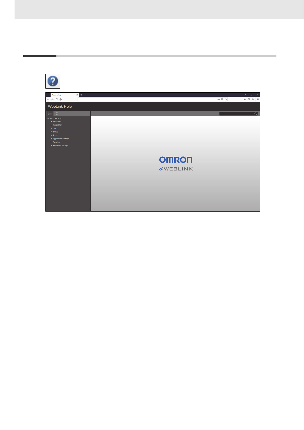
1-5 Help Icon
The help icon is located to the right of the flash icon. Click this icon to open WebLink Help.
1-6
MicroHAWK V320-F / V330-F / V420-F / V430-F Barcode Reader User Manual
Page 23
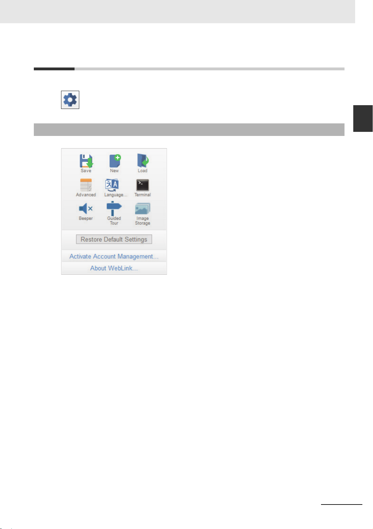
1-6 Application Settings Icon
Click the gear icon to the right of the help icon to open the Application Settings menu.
1 Overview
1-6 Application Settings Icon
1
1-6-1 Application Settings Menu
Note: The Enable USB Drive Mode option only appears when you are using a V420-F, which supports
USB connectivity.
1-6-1 Application Settings Menu
MicroHAWK V320-F / V330-F / V420-F / V430-F Barcode Reader User Manual
1-7
Page 24
1 Overview
1-7 Left Panel
The area to the left of the Image Area is different depending on whether you are in the Start or Setup
view. (In the Run view, the Image Area expands and the left panel is not present.)
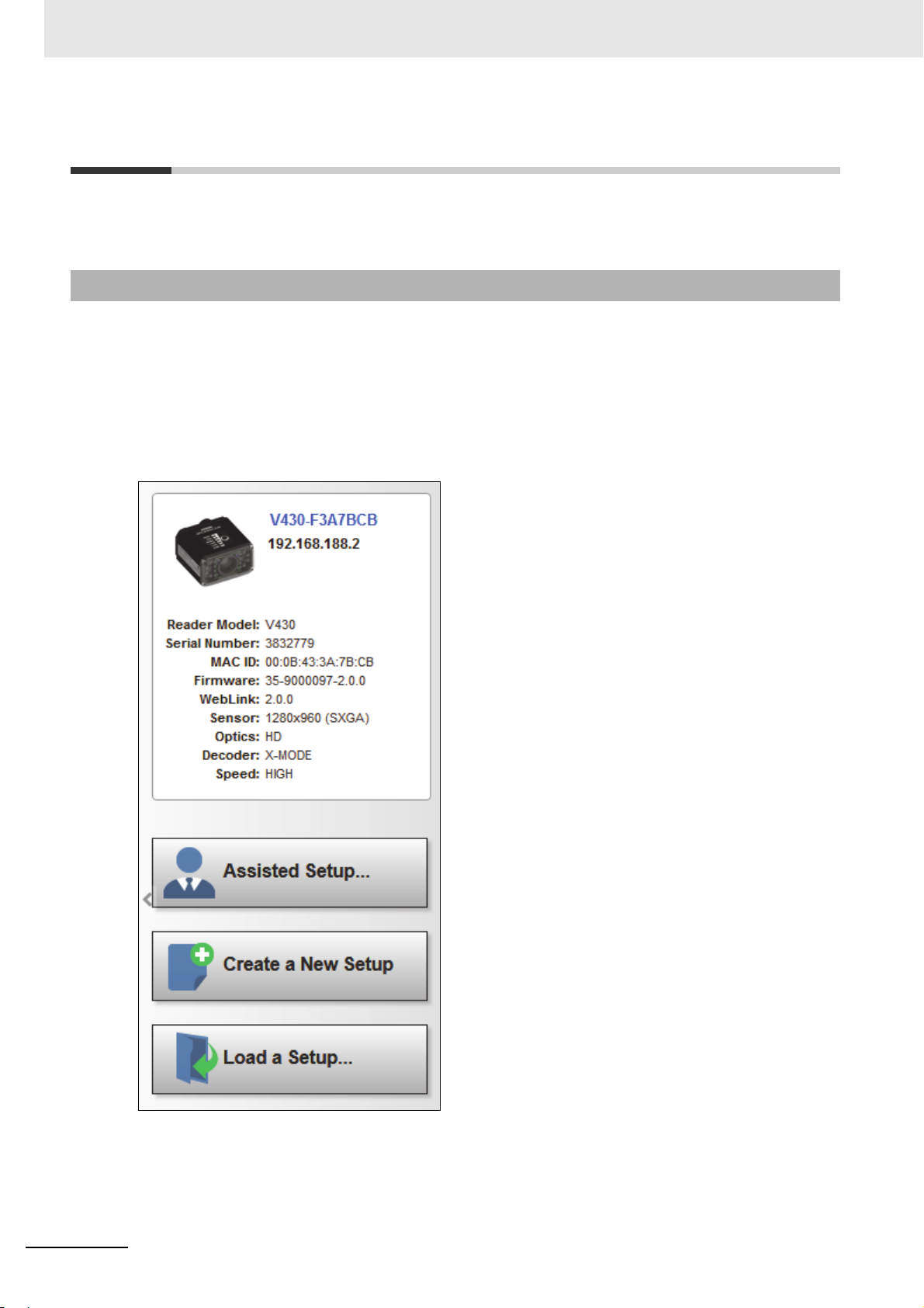
1-7-1 Left Panel in Start View
In the Start view, the left panel shows your reader's user-defined name, IP address, License
Options, Reader Model, Serial Number, MAC ID, Firmware version, WebLink version, Sensor,
Optics, Decoder, and Speed.
Note: The information in this area is selectable so that you can copy it to a clipboard.
Note: The user-defined name must be 19 characters or fewer.
The left panel in the Start view also contains buttons for Assisted Setup, Create a New Setup, and
Load a Setup.
1-8
MicroHAWK V320-F / V330-F / V420-F / V430-F Barcode Reader User Manual
Page 25
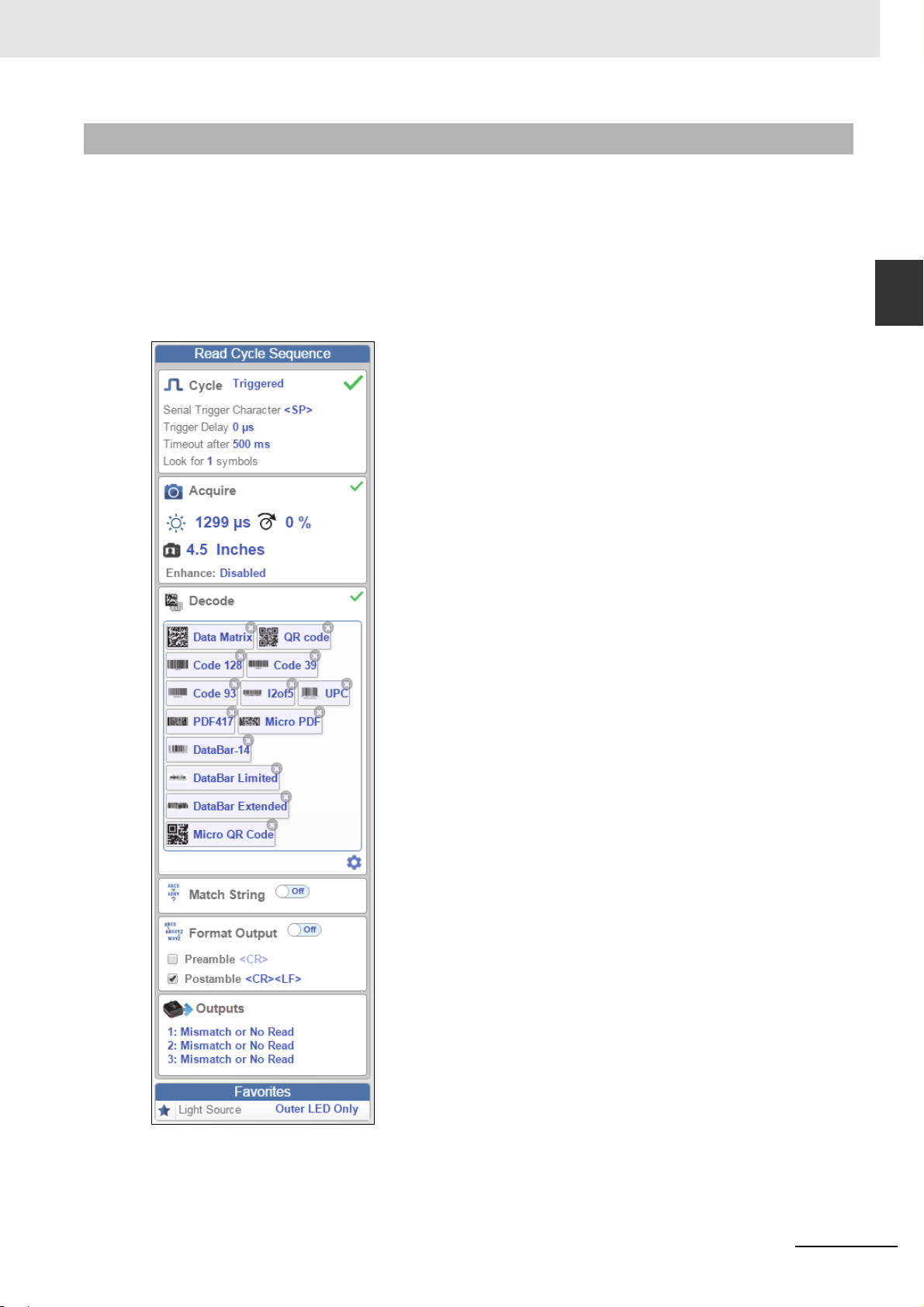
1-7-2 Left Panel in Setup View
In the Setup view, the left panel contains the majority of WebLink's configuration tools: Cycle, which
allows you to set the trigger mode; Acquire, which allows you to set the camera's exposure and gain;
Decode, which allows you to select which code types are required in your application; Match String,
which allows you to set the match code mode, wildcard, text output, new master, and match string
database; Format Output, which allows you to determine the ways in which barcode data can be
formatted before it is output as a data string; Outputs, which allows you to determine output conditions,
the output mode, the pulse width, and the output state (normally open or normally closed); and
Favorites, which allows you to define the commands you use most frequently and gives you quick
access to their command parameters.
1 Overview
1-7 Left Panel
1
1-7-2 Left Panel in Setup View
MicroHAWK V320-F / V330-F / V420-F / V430-F Barcode Reader User Manual
1-9
Page 26
1 Overview
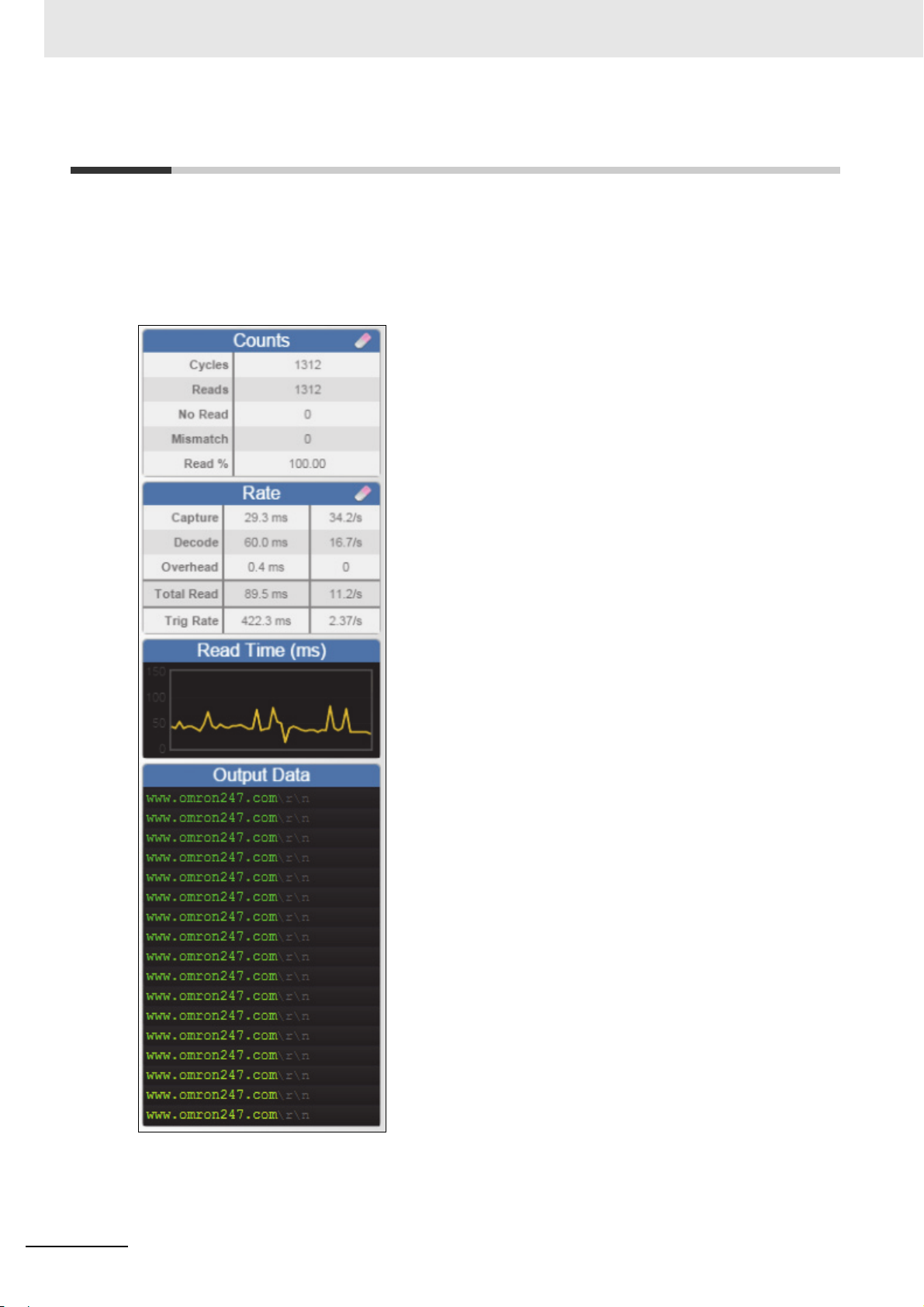
1-8 Right Panel
The area to the right of the Image Area shows counters for Cycles, Reads, No Reads, and Mismatches
(which only applies if you have defined a match string); statistics for the rate of Capture, Decode,
Overhead, Total Read, and Trigger Rate; a line graph representation of read time; and a display area
for the output of decoded data.
You may find the information displayed on this panel to be most useful in the Run view, but it appears in
all three of WebLink's primary views.
1-10
MicroHAWK V320-F / V330-F / V420-F / V430-F Barcode Reader User Manual
Page 27
1 Overview
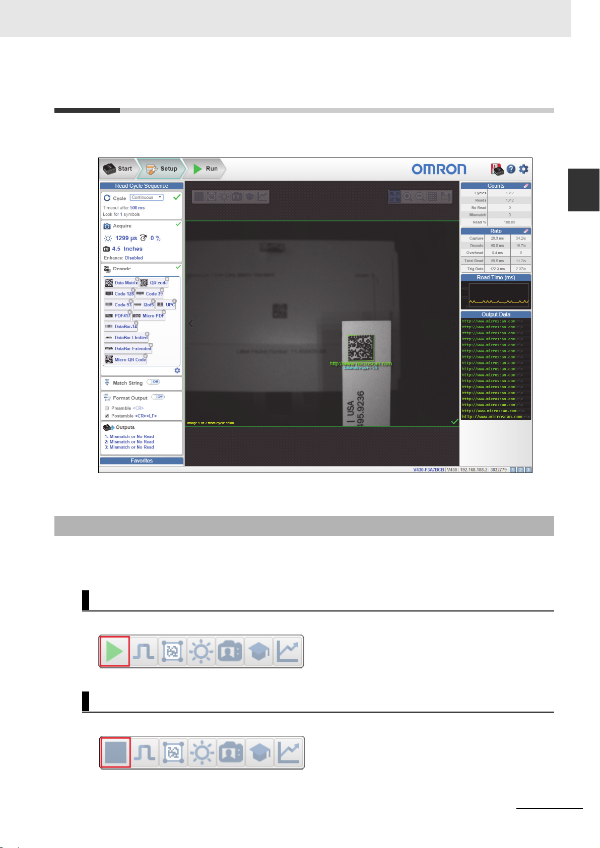
1-9 Image Area
The Image Area is the main focus of WebLink. This area allows you to see what currently falls within
the reader's field of view, and offers several image control tools.
1-9 Image Area
1
1-9-1 Device Control Toolbar
1-9-1 Device Control Toolbar
The Device Control buttons are a convenient way to enable and disable multiple triggering methods and
image processing settings in the camera directly from the Image Area.
Start Read Cycle
Starts the camera's read cycle.
Stop Read Cycle
Stops the camera's read cycle.
MicroHAWK V320-F / V330-F / V420-F / V430-F Barcode Reader User Manual
1-11
Page 28
1 Overview
Send a Serial Trigger to the Reader
Sends a Serial Trigger to the camera.
Set Window of Interest
Allows you to define the Window of Interest directly in the Image Area interface.
Note: When using an SXGA reader with Auto Photometry enabled, the Window of Interest cannot be
set to a width less than 640.
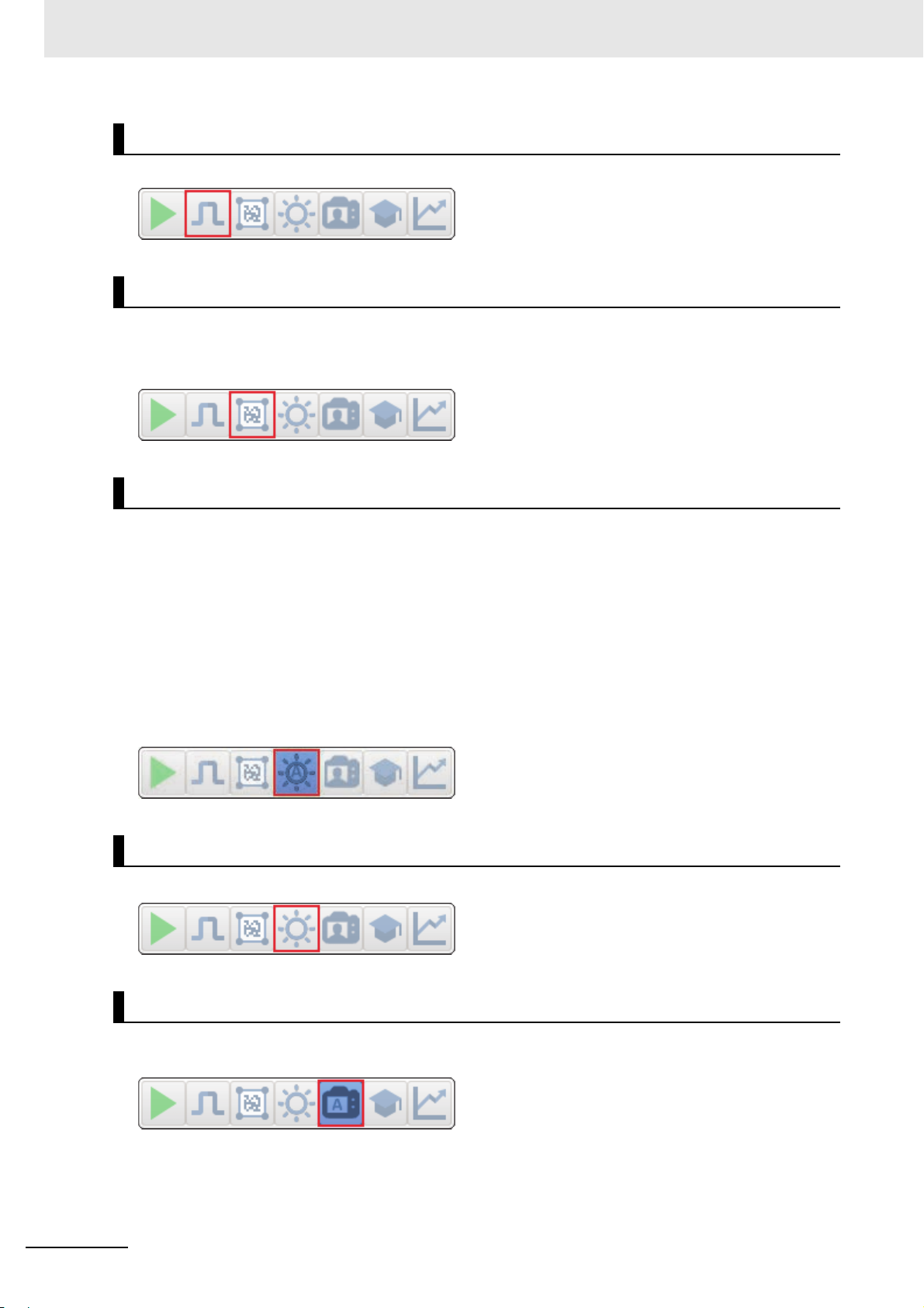
Auto Photometry On
Turns Auto Photometry on. The camera's Auto Photometry settings defined in the Acquire section of
the Setup interface are applied to the image when Auto Photometry is on.
When the reader is in Triggered mode and Auto Photometry is on, the best Exposure and Gain
settings are determined for the next captured image. Auto Photometry functions differently in Triggered
mode than in Continuous mode or Presentation mode: when Auto Photometry is on in Triggered
mode, it is only a one-time setting. Exposure and Gain are not adjusted dynamically with each trigger
as they would be in Continuous mode or Presentation mode.
When the reader is in Continuous mode or Presentation mode and you click the Auto Photometry
button, the reader maintains optimal self-adjusting photometry and focus parameters until you click the
button again to turn Auto Photometry off. Symbol data is decoded and symbol information is transmitted
repeatedly as long as the symbol is within the reader's field of view and read range.
Auto Photometry Off
Turns Auto Photometry off.
1-12
Autofocus On
Turns Autofocus on. The camera's Autofocus settings defined in the Acquire section of the Setup
interface are applied to the image when Autofocus is on.
MicroHAWK V320-F / V330-F / V420-F / V430-F Barcode Reader User Manual
Page 29
1 Overview
Autofocus Off
Turns Autofocus off.
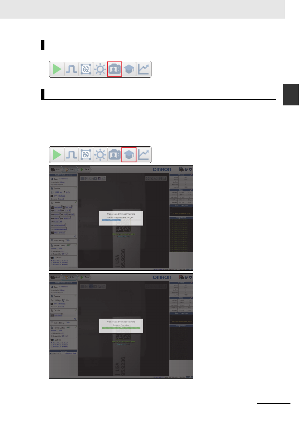
Train
Performs a full symbol calibration to find the best Focus, Exposure, and Gain, and saves relevant
information regarding the decoded target symbol to allow greater decodability of similar symbols.
You will see the Determine parameter ranges... and Training Complete messages shown in the
examples below during the Train operation.
Note: The Train operation will un-optimize the system once an image is processed, but you can
optimize the system again after a Train operation.
1-9 Image Area
1
1-9-1 Device Control Toolbar
MicroHAWK V320-F / V330-F / V420-F / V430-F Barcode Reader User Manual
1-13
Page 30
1 Overview
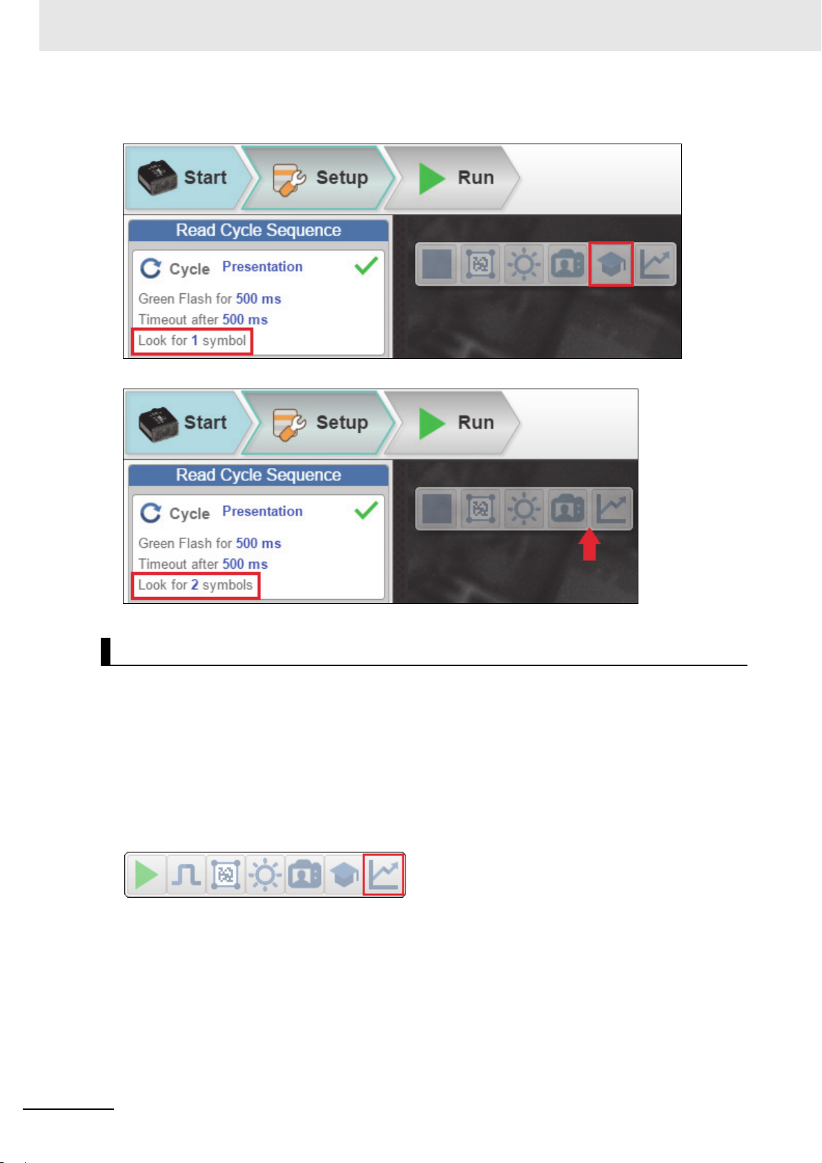
Note: The Train button only appears in the Device Control Toolbar when the Read Cycle is
configured to look for only 1 symbol.
When the Read Cycle is looking for 2 or more symbols, the Train button appears.
Optimize
Saves relevant information about the target symbol, allowing the subsequent symbols to be processed
more quickly and consistently.
The reader has three optimization states: un-optimized, optimizing, and optimized.
When the reader is in the un-optimized state and the Optimize button is clicked, the reader enters the
optimizing state until a symbol is decoded or until the Optimize button is clicked again to deactivate the
optimizing state. When a symbol is decoded during the optimizing state, the reader enters the
optimized state.
Note: A Train operation can reduce decode performance. It will un-optimize the system when an image
is processed. You can re-optimize the system after a Train operation.
1-14
MicroHAWK V320-F / V330-F / V420-F / V430-F Barcode Reader User Manual
Page 31

1 Overview
1-9-2 Image Control Toolbar
Fit Image to Window
Fits the captured image to the Image Area window.
Zoom In
Zooms in on the desired area of the captured image.
Zoom Out
Zooms out and decreases the size of the captured image.
1-9 Image Area
1
1-9-2 Image Control Toolbar
Note: You can also zoom in and out by scrolling up or down with your mouse, and you can move the
image around by clicking and dragging.
Show All Images Used in Read Cycle
Shows all the images that have been captured during the most recent read cycle.
Save Current Image
Allows you to save the current captured image to the location of your choice on your PC.
MicroHAWK V320-F / V330-F / V420-F / V430-F Barcode Reader User Manual
1-15
Page 32

1 Overview
1-10 Guided Tour
The Guided Tour is a multi-step tutorial that explains the functions of the various areas of the WebLink
user interface.
1-10-1 Start View
1-10-2 Reader Info
1-16
MicroHAWK V320-F / V330-F / V420-F / V430-F Barcode Reader User Manual
Page 33

1 Overview
1-10-3 Assisted Setup
1-10 Guided Tour
1
1-10-3 Assisted Setup
1-10-4 New Setup
MicroHAWK V320-F / V330-F / V420-F / V430-F Barcode Reader User Manual
1-17
Page 34

1 Overview
1-10-5 Load Setup
1-10-6 Image Area
1-18
MicroHAWK V320-F / V330-F / V420-F / V430-F Barcode Reader User Manual
Page 35

1 Overview
1-10-7 Control Toolbar
1-10 Guided Tour
1
1-10-7 Control Toolbar
1-10-8 Image Toolbar
MicroHAWK V320-F / V330-F / V420-F / V430-F Barcode Reader User Manual
1-19
Page 36

1 Overview
1-10-9 Save Settings to Reader
1-10-10 Help
1-20
MicroHAWK V320-F / V330-F / V420-F / V430-F Barcode Reader User Manual
Page 37

1 Overview
1-10-11 Settings
1-10 Guided Tour
1
1-10-11 Settings
1-10-12 Counts
MicroHAWK V320-F / V330-F / V420-F / V430-F Barcode Reader User Manual
1-21
Page 38

1 Overview
1-10-13 Rate
1-10-14 Read Time
1-22
MicroHAWK V320-F / V330-F / V420-F / V430-F Barcode Reader User Manual
Page 39

1 Overview
1-10-15 Output Data
1-10 Guided Tour
1
1-10-15 Output Data
1-10-16 Setup View
MicroHAWK V320-F / V330-F / V420-F / V430-F Barcode Reader User Manual
1-23
Page 40

1 Overview
1-10-17 Read Cycle Step
1-10-18 Acquire Step
1-24
MicroHAWK V320-F / V330-F / V420-F / V430-F Barcode Reader User Manual
Page 41

1 Overview
1-10-19 Decode Step
1-10 Guided Tour
1
1-10-19 Decode Step
1-10-20 Match Step
MicroHAWK V320-F / V330-F / V420-F / V430-F Barcode Reader User Manual
1-25
Page 42

1 Overview
1-10-21 Format Output Step
1-10-22 Output Step
1-26
MicroHAWK V320-F / V330-F / V420-F / V430-F Barcode Reader User Manual
Page 43

1 Overview
1-10-23 Favorites
1-10 Guided Tour
1
1-10-23 Favorites
1-10-24 Run View
MicroHAWK V320-F / V330-F / V420-F / V430-F Barcode Reader User Manual
1-27
Page 44

1 Overview
1-10-25 Filmstrip
1-28
MicroHAWK V320-F / V330-F / V420-F / V430-F Barcode Reader User Manual
Page 45

Quick Start
This section is designed to get your MicroHAWK reader up and running quickly using
WebLink. Following these steps will allow you to get a sense of the reader’s
capabilities and to test sample symbols.
2-1 Introduction . . . . . . . . . . . . . . . . . . . . . . . . . . . . . . . . . . . . . . . . . . . . . . . . . . 2-2
2-2 MicroHAWK and WebLink Quick Start . . . . . . . . . . . . . . . . . . . . . . . . . . . . 2-2
2
MicroHAWK V320-F / V330-F / V420-F / V430-F Barcode Reader User Manual
2-1
Page 46

2 Quick Start
2-1 Introduction
There are two ways to configure and test MicroHAWK readers:
• Omron Microscan's
and test your reader without having to install software or access files on a host system
(recommended);
• Serial commands that can be sent from the Terminal in WebLink or from another terminal program.
browser-based WebLink user interface, which enables you to access, configure,
2-2 MicroHAWK and WebLink Quick Start
Important: The following hardware configurations are examples only. Real-world application
configurations may vary considerably from those shown below.
2-2-1 Check Hardware and Connect the System
MicroHAWK V320-F
MicroHAWK V330-F
The V330-F supports Power over Ethernet (POE), allowing you to power and communicate with the device from
a single cable. The V330-F is considered a Class 0 PD (Powered Device) and will operate when connected to
appropriate PoE PSE (Power Sourcing Equipment). The PSE will either provide power on an unused data pair
(Alternative B) or on the data pair (Alternative A) which depends on the PSE. The V330-F supports both Mode A
and Mode B per the PoE standard, IEEE802.3af.
When the V330-F is connected to the Cat5E cable, it will automatically present a Powered Device (PD) signature
to the Power Sourcing Equipment (PSE), or PoE Mid-Span Equipment, when requested. The equipment will then
recognize that a powered device is connected to that line and will supply power.
Omron recommends that you contact your network or IT administrator for further configuration details. You can
connect to a non-PoE network using a PoE Injector, Omron part number V330-AP1.
2-2
MicroHAWK V320-F / V330-F / V420-F / V430-F Barcode Reader User Manual
Page 47

MicroHAWK V420-F
V420-F with DB15 to BUS Power USB Type A
V420-F with DB15 to Ext. Power/USB Type A
Integrated
Corner-Exit
Cable
Accessory USB
Cable to Host
To H o s t
To H ost
Integrated
Corner-Exit
Cable
Accessory USB
Cable to Host
Power Supply
Note: BUS-powered cable delivers reduced illumination –
approximately 30% less brightness.
V420-F with DB15 to Ext. Power/RS-232
Power
Supply
To h ost
Integrated
Corner-Exit
Cable
V420-F with DB15 to Ext. Power/USB, I/O
To
Trigg er
Accessory
USB Cable
to Host
Integrated
Corner-Exit
Cable
To
Power
Supply
2 Quick Start
2-2 MicroHAWK and WebLink
• Mount the reader securely in its stand (not supplied).
• Mount the reader as required by the application.
• Connect the integrated corner-exit cable to the MicroHAWK V420-F.
• Connect the accessory USB cable to the integrated corner-exit cable.
• Connect the USB Type A side of the USB cable to the host.
• Connect the power cable into the power source.
Quick Start
2
2-2-1 Check Hardware and Connect the System
MicroHAWK V320-F / V330-F / V420-F / V430-F Barcode Reader User Manual
2-3
Page 48

2 Quick Start
V420-F with DB15 to USB/RS-232, Triggered
To H o s t
To Trigger
To Power Supply
To H o s t
(RS-232)
Integrated
Corner-Exit
Cable
Accessory
USB Cable
to Host
V420-F with IB-131 and IC-332
To
power
supply
IC-332
To external
trigger
To
Host
2-4
MicroHAWK V320-F / V330-F / V420-F / V430-F Barcode Reader User Manual
Page 49

MicroHAWK V430-F
To P o w e r
Supply
(12-Pin Plug)
To H ost
(Ethernet
8-Pin Plug
to RJ45)
V430-F Simple Configuration
Common
(12-Pin Plug
to 12-Pin
Socket)
To H o s t
(Ethernet
8-Pin Plug
to RJ45)
To Trigger
To P ow er
Supply
V430-F with QX-1 Interface Device
V430-F M12 12-Pin Socket to 9-Pin Socket and M12 Plug
To Power Supply or: Flying Lead Cable
(61-000167-02); QX-1; MS-Connect 210.
To H ost
(RS-232)
To E t her n et
2 Quick Start
2-2 MicroHAWK and WebLink
• Mount the reader securely in its stand (not supplied).
• Mount the reader as required by the application.
• Connect the power cable to the MicroHAWK V430-F.
• Connect the Ethernet cable to the MicroHAWK V430-F.
• Connect the Ethernet cable to the host.
• Connect the power cable into the power source.
Quick Start
2
2-2-1 Check Hardware and Connect the System
Important: See Appendix A for V320-F, V330-F, V420-F, and V430-F pin assignments and hardware
configurations.
MicroHAWK V320-F / V330-F / V420-F / V430-F Barcode Reader User Manual
2-5
Page 50

2 Quick Start
Reader and Symbol Orientation
2-2-2 Mount and Position the Reader
• Position the reader several inches from the symbol. You may need to reposition the reader a few
times to find the ideal distance.
• Tip the reader relative to the symbol to avoid the glare of direct (specular) reflection.
• Symbols can be rotated (tilted) at any angle; however, for best results symbols should be aligned with
the field of view. In the case of linear symbols, aligning the bars in the direction of their movement
(ladder orientation) will minimize the chances of blurring and will result in more consistent decodes.
• Important: Avoid excessive skew or pitch. Maximum skew is ±30°; maximum pitch is ±30°. The
illustration below shows approximate skew axis, pitch axis, and tilt axis.
2-6
MicroHAWK V320-F / V330-F / V420-F / V430-F Barcode Reader User Manual
Page 51

2-2-3 Connect to WebLink
Static Connection
• Navigate to Control Panel > Network and Sharing Center on your PC.
• Click Local Area Connection 4. In the Status dialog, click Properties.
• In the Local Area Connection Properties dialog, select Internet Protocol Version 4 (TCP/IPv4)
and click Properties again. Set your PC to a 192.168.188.X IP address (192.168.188.5, for example).
• Click OK.
• Open a web browser and type the reader’s default IP address (http://192.168.188.2) in the web
browser’s address bar.
The reader will connect to WebLink.
DHCP Network Connection
• Plug your reader into the your network adapter.
• Connect to the reader via Ethernet TCP/IP.
• Click Search to find the reader. When the reader appears in the field below the Search and Send
buttons, select it.
• Change the reader from Static to DHCP and click Send and Save. The reader will reboot.
• When the reader is found, note the new IP address that is generated.
• Open a browser and type the new IP address.
WebLink will load.
2 Quick Start
2-2 MicroHAWK and WebLink
Quick Start
2
2-2-3 Connect to WebLink
Use the Device Discovery Utility (DDU) to Connect to WebLink
You can also connect to WebLink with Omron Microscan's Device Discovery Utility, available in the
Download Center on the Omron Microscan website.
Once you have downloaded the Device Discovery Utility .exe file from Omron Microscan's website and
installed the utility, select Device Discovery Utility from your Start Menu.
MicroHAWK V320-F / V330-F / V420-F / V430-F Barcode Reader User Manual
2-7
Page 52

2 Quick Start
The following screen will appear.
When your reader is located on the network, its identifying information will be shown as in the example below.
2-8
MicroHAWK V320-F / V330-F / V420-F / V430-F Barcode Reader User Manual
Page 53

Click on your reader to bring up the information and settings view.
2 Quick Start
2-2 MicroHAWK and WebLink
Quick Start
2
2-2-3 Connect to WebLink
Click Open WebLink. The WebLink splash screen will appear as the program opens.
MicroHAWK V320-F / V330-F / V420-F / V430-F Barcode Reader User Manual
2-9
Page 54

2 Quick Start
2-2-4 Configure Daisy Chain (If Required by Application)
Daisy Chain is useful in applications where:
• More than one symbol type is present;
• A symbol may be present on multiple sides of a package;
• Symbols are presented at different depths;
• Multiple readers are required to cover a large field of view;
• There is a need to find a symbol on a circular object in any orientation.
A Daisy Chain consists of one parent and one or more child devices. The child devices report their
data to the parent, which then reports the data to the network, effectively allowing all readers to act as
one. In other words, the outside world interacts with one unit – the parent reader.
The Device Discovery Utility (DDU) is used to configure the Daisy Chain group where the parent
reader and the child readers are defined. The parent reader interacts with a host computer or PLC. A
parent reader that receives a trigger will send a trigger to each of the child readers. Any symbol
decoded by the child readers will be communicated to the parent, which collects all of the decodes from
the children and will communicate them to the host.
Overview of Setup Process
Use the Device Discovery Utility to define the Daisy Chain group, the parent reader, and the child
readers.
Use WebLink to configure each of the readers in the Daisy Chain group as desired for the application.
Tips
The parent reader should:
• Configure for application requirements: Match String, Format Output, Trigger, (Digital) Outputs, etc.
The child readers should:
• Use a Triggered cycle, such as External Edge.
• Use a timeout that occurs before the end of read cycle on the parent reader.
Parent and child readers should:
• Save settings to the flash memory of the readers.
2-10
MicroHAWK V320-F / V330-F / V420-F / V430-F Barcode Reader User Manual
Page 55

2 Quick Start
Setting Up a Daisy Chain Configuration with the Device Discovery Utility (DDU)
2-2 MicroHAWK and WebLink
If your application requires readers to be deployed in a Daisy Chain configuration, the DDU can help
you create such a configuration.
A Daisy Chain is a grouping of 2 to 8 readers that function as one. The DDU interface allows you to
manage Daisy Chains, including their creation, monitoring, and deletion.
Connect 2 to 8 V430-F readers that have Daisy Chain-compatible firmware. From the DDU home page,
click on the group icon located near the top-right.
On the Groups page, assign a Group Name and click Create. This opens the interface that allows you
to create a new Daisy Chain.
Important: Only Daisy Chain-enabled readers will appear in this view.
Quick Start
2
2-2-4 Configure Daisy Chain (If Required by Application)
The five most important areas in the Daisy Chain creation interface are:
• Group Information: Contains the Group Name, Total Count, Parent Count, and Children Count of
the Daisy Chain being created. This information is dynamically updated as you make changes. The
Group Name text box is editable, and a group name must be provided to create a new Daisy Chain.
MicroHAWK V320-F / V330-F / V420-F / V430-F Barcode Reader User Manual
2-11
Page 56

2 Quick Start
• All Devices: Contains all Daisy Chain-enabled devices that appear on the network. Devices are
represented by an image, a model, and an IP address. Each device is clickable. You can search for
specific devices using the Filter Devices search box.
•Parent: The Parent container is empty upon opening the interface. This container is used to store the
Parent reader in the Daisy Chain. A maximum of one device can be placed in the Parent container. A
minimum of one device must be placed here to create the Daisy Chain.
• Children: The Children container is empty upon opening the interface. This container is used to store
the Children readers in the Daisy Chain. A minimum of one device must be placed here to create a
Daisy Chain, and a maximum of seven devices may be placed here.
•Buttons: This section of the interface includes the Create, Clear, and Exit buttons.
•Create creates a new Daisy Chain if all the necessary conditions are met.
Note: The Create function does not delete a Daisy Chain and only resets the interface.
•Clear resets the interface to its original state.
•Exit closes the window.
Below these buttons, messages will appear that indicate any errors in the potential Daisy Chain being
created. These errors appear and disappear based on dynamic validation of user input.
The Daisy Chain creation interface is drag-and-drop, meaning you can move devices around the page
to build your Daisy Chain.
The All Devices, Parent, and Children containers are drop zones for readers. To move a device, place
the cursor over a device, left-click, and hold down. Then drag the device in another drop zone by
moving the cursor / reader over it and releasing your mouse's left-click button. Valid reader drop zone
areas are designated by the dotted grey line surrounding them.
Drag and drop a reader into the Parent drop zone. Drag and drop one or more other Daisy-Chain-enabled
readers into the Children drop zone. Assign a name to the group.
2-12
MicroHAWK V320-F / V330-F / V420-F / V430-F Barcode Reader User Manual
Page 57

2 Quick Start
If errors occur (A group name must be assigned or Group must consist of at least one parent and one
child), resolve them as needed, and then you will see that the Create button will be active. A valid Daisy
Chain configuration should resemble the example below.
2-2 MicroHAWK and WebLink
Quick Start
2
2-2-4 Configure Daisy Chain (If Required by Application)
If the Daisy Chain was created successfully, the popup will close, and the newly established Daisy
Chain will be displayed as a diagram or map. This diagram is generated based on the number of
devices in the Daisy Chain. Whichever number of devices in the Daisy Chain, the Parent always
appears above and all Children devices below.
MicroHAWK V320-F / V330-F / V420-F / V430-F Barcode Reader User Manual
2-13
Page 58

2 Quick Start
There is no limit on the number of Daisy Chains that can be created. All current, active Daisy Chains
will appear on the Daisy Chain page in the DDU. Click on any Daisy Chain to open its information
popup. This popup contains information about the Daisy Chain configuration, including Group
Information, Parent reader identity, and Children reader identities. The Daisy Chain information popup
also contains a Delete button, which deletes the entire Daisy Chain configuration – Parent and Children.
Daisy Chain Fundamentals
Parent: The master device in the group. Responsible for establishing the group on the firmware side
and reporting the Daisy Chain to the DDU. There can be only one Parent in a Daisy Chain. The parent
is responsible for receiving create and delete commands from the DDU.
Children: Any reader that is currently a part of a Daisy Chain that is not the Parent device is a Child
device. Child readers report data to the Parent reader.
A Valid Daisy Chain:
• Must have at least two readers;
• Must consist of V430-F readers;
• Must contain one Parent reader;
• Must contain one or more Child readers (up to 8);
• Must have a group name less than 25 characters in length;
• Must have a valid group name [ a-z, A-Z, 0-9, _, – ]
2-14
MicroHAWK V320-F / V330-F / V420-F / V430-F Barcode Reader User Manual
Page 59

2 Quick Start
The creation and deletion of Daisy Chains occurs via UDP messages that are sent from the DDU user
interface to the readers. If a parent device recognizes that it has been configured in a Daisy Chain, it
creates the firmware connection, and then broadcasts UDP messages that contain all the information
needed by the user interface to produce a functional Daisy Chain configuration. The user interface will
only create a new Daisy Chain if it receives a broadcast from the Parent device with the Daisy Chain
information. The core communication between the user interface and the devices(s) is via the Parent
device. The firmware is responsible for connecting the Parent device to the Children devices and then
reporting the status.
A Daisy Chain consists of one Parent and one or more Children devices. The Children devices report
their data to the Parent, which then reports the data to the network, effectively allowing all readers to act
as one.
2-2 MicroHAWK and WebLink
Quick Start
2
2-2-4 Configure Daisy Chain (If Required by Application)
Error Handling
If the Parent reader in a Daisy Chain is turned off for more than one minute, a Disconnected notice will
appear in the dialog. This notice will disappear once the Parent reader is turned back on.
MicroHAWK V320-F / V330-F / V420-F / V430-F Barcode Reader User Manual
2-15
Page 60

2 Quick Start
If a Child reader in a Daisy Chain is turned off, even temporarily, an Offline notice will appear below the
respective Child on the reader map. Once turned back on, the Offline notice will disappear.
Some errors can occur when you have already established a Daisy Chain and confirmed that it’s
working.
In this hypothetical error scenario, the Parent reader = P, the first Child reader = C1, the second Child
reader = C2, and the third Child reader = C3.
The user shuts down the application and completely turns off power on P, C1, C2, and C3. The user
comes in the following day and turns on all the devices except C3 and then starts the application.
The complete Daisy Chain can’t be re-initiated because it is missing a unit. To account for this, the
application will place a “dummy device” in place of the missing C3. The dummy device will display an
error icon, the missing device's MAC address, and an Offline status message. It will continue show this
status if the browser is restarted. This offline device can’t be clicked in the Daisy Chain info page. It is
only there to alert the user of the missing device.
If the user turns on C3 when seeing the status shown in the diagram above, the application will
automatically resolve the issue and a new, fully-formed Daisy Chain with C3 as a full device will be
created. There is no need to restart the browser or Parent device.
2-16
MicroHAWK V320-F / V330-F / V420-F / V430-F Barcode Reader User Manual
Page 61

2-2-5 Explore the Start View
2 Quick Start
2-2 MicroHAWK and WebLink
The Start view is the initial view you will see when the WebLink session begins. The connected reader
is shown, along with its user-defined name, IP address, License Options, Reader Model, Serial
Number, MAC ID, Firmware version, WebLink version, Sensor, Optics, Decoder, and Speed.
Note: The user-defined name must be 19 characters or fewer.
This view allows you to choose Assisted Setup, to Create a New Setup, or to Load a Setup.
Quick Start
2
2-2-5 Explore the Start View
MicroHAWK V320-F / V330-F / V420-F / V430-F Barcode Reader User Manual
2-17
Page 62

2 Quick Start
2-2-6 Create a New Setup or Load an Existing Setup
Assisted Setup
When you click the Assisted Setup button in the Start view, a dialog will appear asking you a series of
application-based questions. Based on your answers, WebLink generates your initial setup
automatically. Once the setup is created, you can fine-tune its parameters in the Setup view.
2-18
MicroHAWK V320-F / V330-F / V420-F / V430-F Barcode Reader User Manual
Page 63

Create a New Setup
2 Quick Start
2-2 MicroHAWK and WebLink
The Start view also allows you to Create a New Setup without using Assisted Setup. When you click
the Create a New Setup button, WebLink searches for any differences from default in the reader
parameters. If no differences from default are found, you will see the Setup view. If differences from
default are found, an alert will appear asking if you want to restore default settings.
Load a Setup
Select Load a Setup to load an existing .json WebLink setup file.
Quick Start
2
2-2-6 Create a New Setup or Load an Existing Setup
MicroHAWK V320-F / V330-F / V420-F / V430-F Barcode Reader User Manual
2-19
Page 64

2 Quick Start
2-2-7 Explore the Setup View
The Setup view allows you to configure all aspects of a setup. Multiple discrete sections of the interface
give you the ability to set Cycle, Acquire, Decode, Match String, Format Output, Output
parameters, and Favorites.
Clicking the Save icon at the upper right saves current settings to the reader’s flash memory so the
settings will be available when the reader is rebooted.
The question mark icon at the upper right opens WebLink Help.
The gear icon at the upper right brings up the Application Settings menu.
Note: The 1, 2, and 3 output indicators at the lower right of the screen display the results of the last
read cycle.
2-20
MicroHAWK V320-F / V330-F / V420-F / V430-F Barcode Reader User Manual
Page 65

2-2-8 Configure Read Cycle Settings
2 Quick Start
2-2 MicroHAWK and WebLink
The Cycle section of the Setup view allows you to modify the trigger, determine the number of symbols
for the reader to expect, and set Read Cycle Timeout. A dropdown menu of various Cycle types
provides a variety of options, each with configurable parameters.
Presentation
This mode uses Continuous Read Auto along with Continuous Capture Mode and a Timeout at
End of Read Cycle. Green Flash Mode is set to Static Presentation and the Green Flash Duration
is set to 1 second.
Continuous
This mode allows you to set the Read Cycle Timeout and the expected Number of Symbols from 1
to 100.
Quick Start
2
2-2-8 Configure Read Cycle Settings
Triggered
This mode sets the read cycle to Serial Data and Edge, End of Read Cycle is set to Timeout or
New Trigger, and Capture Mode is set to Rapid Capture with 1 capture. You can adjust the Serial
Trigger, Trigger Delay, Timeout, and Number of Symbols.
Start / Stop
This mode uses External Level with a Read Cycle Timeout and Continuous Capture, allowing you
to set Leading Edge and Trailing Edge as well as the Serial Trigger and the Start and Stop
characters.
Serial Trigger (Non-Delimited) Off
When Serial Trigger is set to Off, the start and stop characters are set to NULL, meaning that the
trigger is disabled.
MicroHAWK V320-F / V330-F / V420-F / V430-F Barcode Reader User Manual
2-21
Page 66

2 Quick Start
Serial Trigger (Non-Delimited) On
When Serial Trigger is set to On, the start and stop characters are set to S and E. When the trigger
button is clicked, it will use the current start and stop non-delimited triggers.
Custom
This mode allows you a wider variety of read cycle scenarios, including Continuous Read Auto. Use
this mode to select Trigger mode and to set Serial Trigger Character and Trigger Delay; to select
Capture mode and to set Number of Captures, Rapid Capture mode, and Delay between Images;
and to select the End Cycle On setting as well as Timeout and Number of Symbols.
2-22
MicroHAWK V320-F / V330-F / V420-F / V430-F Barcode Reader User Manual
Page 67

2-2-9 Configure Acquire Settings
Standard
Auto Photometry
2 Quick Start
2-2 MicroHAWK and WebLink
Acquire settings allow you to set Exposure (signified by the sun icon) and Gain (signified by the dial
and right-pointing arrow icon) in real time. Clicking any of these settings will
allowing you to modify that setting. Settings take effect immediately.
• Important: There are 4 levels of Gain in SXGA readers. Each level corresponds to 25 percentage
points, or one quarter turn of the Gain dial shown at left.
• Level 1 = 0 to 24%
• Level 2 = 25 to 49%
• Level 3 = 50 to 74%
• Level 4 = 75 to 100%
When Auto Photometry is enabled instead of Standard, Exposure and Gain are read-only. The A
shown on the sun and dial icons signifies that Auto Photometry is enabled. Auto
determines the best Exposure and Gain settings during each read cycle.
cause a control to appear,
Photometry constantly
Quick Start
2
2-2-9 Configure Acquire Settings
Autofocus
Autofocus can be enabled and disabled in the Image Area using the focus button in the Device
Control Toolbar, and can be configured in the Acquire section of the Setup view.
While in Continuous mode or Continuous Auto mode, the reader can enable or disable Autofocus
functionality, allowing it to refocus after a number of no reads. The focus button shows an A when
Autofocus is enabled. The focus distance is updated on the fly based on the latest refocus settings.
MicroHAWK V320-F / V330-F / V420-F / V430-F Barcode Reader User Manual
2-23
Page 68

2 Quick Start
Spot Focus
If the reader is in Continuous mode or Continuous Auto (Continuous mode with Auto Photometry
enabled), you can perform a localized quick focus in the image.
If you click the focus button, the Autofocus and Spot Focus icons appear:
When you click the Spot Focus icon, the Select a location in the image to autofocus message
appears:
The cursor transforms into crosshairs as shown in the example below. This allows you to select the
section of the image in which you want to perform a quick focus.
Note: If you click the Autofocus button to the left of the Spot Focus button, the reader will switch from
Spot Focus to regular Autofocus functionality. If the reader is in Triggered mode, only the Spot Focus
icon will appear.
2-24
MicroHAWK V320-F / V330-F / V420-F / V430-F Barcode Reader User Manual
Page 69

Enhance
2 Quick Start
2-2 MicroHAWK and WebLink
The Enhance dropdown menu at the bottom of the Acquire settings editor allows you to select the
method for processing captured images.
Grow Dark
Grow Dark increases the dark cell size of a symbol. It is useful for increasing the dark cell size of a
dark-on-light Data Matrix symbol.
Shrink Dark
Shrink Dark increases the light cell size of a symbol. It is useful for increasing the light cell size of a
light-on-dark Data Matrix symbol.
Connect Dark
Connect Dark removes minor light defects of dark cells.
Separate Dark
Separate Dark removes minor dark defects of light cells.
Quick Start
2
2-2-9 Configure Acquire Settings
Operator Size
The Operator Size dropdown menu determines the size of the area or “pixel neighborhood” in which the
enhance operation is being performed.
Small
Small corresponds to an area of 3 pixels by 3 pixels.
Medium
Medium corresponds to an area of 5 pixels by 5 pixels.
Large
Large corresponds to an area of 7 pixels by 7 pixels.
MicroHAWK V320-F / V330-F / V420-F / V430-F Barcode Reader User Manual
2-25
Page 70

2 Quick Start
Data Matrix error correction parameters are shown in this
example, but you can configure any parameter for any of
the code types supported by WebLink. All parameter
changes for all code types take effect immediately.
2-2-10 Configure Symbology Settings
Clicking the gear icon at the bottom of the Decode dialog brings up Symbology Settings. This allows
you to configure every parameter for every available code type.
2-26
MicroHAWK V320-F / V330-F / V420-F / V430-F Barcode Reader User Manual
Page 71

2-2-11 Format Output and Configure Match String
2 Quick Start
2-2 MicroHAWK and WebLink
Format Output, when enabled in the Setup view, allows you to determine the many ways in which
barcode data can be formatted and parsed before it is output as a data string. You can also set
Preamble and Postamble in this dialog.
Quick Start
2
2-2-11 Format Output and Configure Match String
MicroHAWK V320-F / V330-F / V420-F / V430-F Barcode Reader User Manual
2-27
Page 72

2 Quick Start
Match Options and Match String Database, accessible by clicking the Match String section in the
Setup view, allow you to set the match code mode, text output, new master, and match string database.
2-28
MicroHAWK V320-F / V330-F / V420-F / V430-F Barcode Reader User Manual
Page 73

2-2-12 Configure Output 1, 2, and 3 Settings
Bring up the Output 1, Output 2, and Output 3 dialogs by clicking on the Outputs section at the lower
left of the Setup view. For each output you can determine the Output On behavior, Mode, Pulse
Width, and State. Outputs 2 and 3 also allow you to determine output behavior based on Tre nd
Options parameters or Verification Options parameters.
This example shows the dialog that appears when you click Symbol Quality Options. A similar dialog
would also appear for Trend Options under Output 2.
Note: The 1, 2, and 3 output indicators at the lower right of the screen display the results of the last
read cycle.
2 Quick Start
2-2 MicroHAWK and WebLink
Quick Start
2
2-2-12 Configure Output 1, 2, and 3 Settings
MicroHAWK V320-F / V330-F / V420-F / V430-F Barcode Reader User Manual
2-29
Page 74

2 Quick Start
2-2-13 Run the Application
In the Run view, you can observe the progress of the setup as it follows the parameters you have
defined. The right panel of the UI shows Counts for Cycles, Reads, No Reads, and Mismatches, as
well as Rate information for Capture, Decode, Overhead, Total Read, and Trigger Rate, as well as
Output Data. A "filmstrip" below the Image Area shows each image capture with a green check mark
for a good read and a red x for a no read.
2-30
MicroHAWK V320-F / V330-F / V420-F / V430-F Barcode Reader User Manual
Page 75

Start
3
The Start view is the initial view you will see when the WebLink session begins.
3-1 Overview . . . . . . . . . . . . . . . . . . . . . . . . . . . . . . . . . . . . . . . . . . . . . . . . . . . . . 3-2
3-2 Assisted Setup . . . . . . . . . . . . . . . . . . . . . . . . . . . . . . . . . . . . . . . . . . . . . . . 3-4
3-3 Reader Information . . . . . . . . . . . . . . . . . . . . . . . . . . . . . . . . . . . . . . . . . . . . 3-5
3-4 Setup Button . . . . . . . . . . . . . . . . . . . . . . . . . . . . . . . . . . . . . . . . . . . . . . . . . 3-7
MicroHAWK V320-F / V330-F / V420-F / V430-F Barcode Reader User Manual
3-1
Page 76

3 Start
3-1 Overview
The connected reader is shown, along with its user-defined name, IP address, License Options,
Reader Model, Serial Number, MAC ID, Firmware version, WebLink version, Sensor, Optics,
Decoder, and Speed.
Note: The user-defined name must be 19 characters or fewer.
This view also allows you to choose Assisted Setup, to Create a New Setup, or to Load a Setup.
Click the gear icon at the upper right to bring up the Application Settings menu. This menu includes
several functions: Save, New, Load, Advanced, Language, Terminal, Beeper, Guided Tour, Image
Storage, Restore Default Settings, Active Account Management, and About WebLink.
Note: The Enable USB Drive Mode options only appears when you are using a device that supports
USB connectivity.
3-2
MicroHAWK V320-F / V330-F / V420-F / V430-F Barcode Reader User Manual
Page 77

3 Start
Clicking About WebLink opens the dialog shown below, which shows the current WebLink version,
Reader Model, Serial Number, Part Number, MAC ID, Sensor, Firmware version, Boot version,
Decoder, Speed, Browser, Operating System, and Screen Resolution.
Note: The information in this dialog is selectable so that you can copy it to a clipboard.
Clicking Contact us... takes you to the Omron Microscan website.
3-1 Overview
3
MicroHAWK V320-F / V330-F / V420-F / V430-F Barcode Reader User Manual
3-3
Page 78

3 Start
3-2 Assisted Setup
When you click the Assisted Setup button in the Start view, a dialog will appear asking you a series of
application-based questions. Based on your answers, WebLink generates your initial setup
automatically. Once the setup is created, you can fine-tune its parameters in the Setup view.
The Assisted Setup dialog is designed to be logical and intuitive, and follows this sequence:
• You are asked which code types you will be reading in your application. Code types can be added by
clicking directly in the code type field and selecting them from a dropdown menu.
• Then you are asked how many codes you need to read at once (in a single read cycle). Type the
number of codes you need to read directly in the text field or select a number using the up and down
arrows.
• You are then given a selection of four application types, which represent the available selections in
the Cycle area of the left panel in the Setup view. The icons represent the Presentation,
Continuous, Triggered, and Start / Stop Cycle Types.
• The next question is whether or not you need the decoded data to match an existing string of data.
This enables or disables Match String.
• If the answer to the previous question is Yes, a follow-up question appears asking for the exact
output string that the decoded data must match. If the answer to the previous question is No, the
follow-up question does not appear.
• Finally, you are asked if you want to rename the reader. If Yes, a text field appears in which you can
type the reader's new name. The reader's MAC ID is also shown to the right of the text field.
Click Create Setup to configure your WebLink setup automatically based on your answers to the
Assisted Setup questions.
Note: Reader settings are defaulted when Assisted Setup settings take effect.
3-4
MicroHAWK V320-F / V330-F / V420-F / V430-F Barcode Reader User Manual
Page 79

3-3 Reader Information
The Reader Information section of the left panel of the Start view shows your reader's user-defined
name, IP address, Reader Model, Serial Number, MAC ID, Firmware version, WebLink version,
Sensor, and Optics.
Note: The user-defined name must be 19 characters or fewer.
3 Start
3-3 Reader Information
3
MicroHAWK V320-F / V330-F / V420-F / V430-F Barcode Reader User Manual
3-5
Page 80

3 Start
3-4 Setup Buttons
3-4-1 Assisted Setup
When you click the Assisted Setup button in the Start view, a dialog with a series of questions about
your application will appear. Answering these simple questions allows WebLink to configure your setup
for you.
3-4-2 Create a New Setup
New Setup allows you to create a new setup without using Assisted Setup. When you click the New
Setup button, WebLink searches for any differences from default in the reader parameters. If no
differences from default are found, you will see the Setup view. If differences from default are found,
the following alert will appear, allowing you to choose whether to restore the reader to default settings
or to cancel the New Setup.
3-4-3 Load a Setup
Select Load Setup to load an existing .json WebLink setup file.
3-6
MicroHAWK V320-F / V330-F / V420-F / V430-F Barcode Reader User Manual
Page 81

Setup
4
The Setup view allows you to configure all aspects of a setup. Multiple discrete
sections of the WebLink interface give you the ability to set Cycle, Acquire, Decode,
Match String, Format Output, Outputs, Configuration Database, and Favorites.
4-1 Cycle . . . . . . . . . . . . . . . . . . . . . . . . . . . . . . . . . . . . . . . . . . . . . . . . . . . . . . . . 4-2
4-2 Acquire . . . . . . . . . . . . . . . . . . . . . . . . . . . . . . . . . . . . . . . . . . . . . . . . . . . . . . 4-4
4-3 Decode . . . . . . . . . . . . . . . . . . . . . . . . . . . . . . . . . . . . . . . . . . . . . . . . . . . . . . 4-7
4-4 Match String . . . . . . . . . . . . . . . . . . . . . . . . . . . . . . . . . . . . . . . . . . . . . . . . . . 4-9
4-5 Format Output . . . . . . . . . . . . . . . . . . . . . . . . . . . . . . . . . . . . . . . . . . . . . . . 4-13
4-6 Outputs . . . . . . . . . . . . . . . . . . . . . . . . . . . . . . . . . . . . . . . . . . . . . . . . . . . . . 4-17
4-7 Configuration Database. . . . . . . . . . . . . . . . . . . . . . . . . . . . . . . . . . . . . . . . 4-19
4-8 Favorites . . . . . . . . . . . . . . . . . . . . . . . . . . . . . . . . . . . . . . . . . . . . . . . . . . . . 4-25
MicroHAWK V320-F / V330-F / V420-F / V430-F Barcode Reader User Manual
4-1
Page 82

4 Setup
4-1 Cycle
The Cycle section of the Setup view allows you to modify the trigger, determine the number of symbols
for the reader to expect, and set Read Cycle Timeout. A dropdown menu of various Cycle types
provides a variety of options, each with configurable parameters.
4-1-1 Presentation
This mode uses Continuous Read Auto along with Continuous Capture Mode and a Timeout at
End of Read Cycle. Green Flash Mode is set to Static Presentation and the Green Flash Duration
is set to 250 ms.
4-1-2 Continuous
This mode allows you to set the
4-1-3 Triggered
This mode sets the read cycle to Serial Data and Edge, End of Read Cycle is set to Timeout or New
Trigger, and Capture Mode is set to Rapid Capture with 1 capture. You can adjust the Serial Trigger,
Trigger Delay, Timeout, and Number of Symbols.
Read Cycle Timeout
and the expected
Number of Symbols
from 1 to
100
.
4-1-4 Start / Stop
This mode uses External Level with a Read Cycle Timeout and Continuous Capture, allowing you
to set Leading Edge and Trailing Edge as well as the Serial Trigger and the Start and Stop
Characters.
4-2
MicroHAWK V320-F / V330-F / V420-F / V430-F Barcode Reader User Manual
Page 83

4 Setup
Serial Trigger (Non-Delimited) Off
When Serial Trigger is set to Off, the start and stop characters are set to NULL, meaning that the
trigger is disabled.
Serial Trigger (Non-Delimited) On
When Serial Trigger is set to On, the start and stop characters are set to S and E. When the trigger
button is clicked, it will use the current start and stop non-delimited triggers.
Custom
This mode allows you a wider variety of read cycle scenarios, including Continuous Read Auto. Use
this mode to select Trigger mode and to set Serial Trigger Character and Trigger Delay; to select
Capture Mode and to set Number of Captures, Rapid Capture Mode, and Delay between Images;
and to select the End Cycle On setting as well as Timeout and Number of Symbols.
4-1 Cycle
4
4-1-4 Start / Stop
MicroHAWK V320-F / V330-F / V420-F / V430-F Barcode Reader User Manual
4-3
Page 84

4 Setup
Standard
Important: There are 4 levels of Gain in SXGA
MicroHAWK ID readers. Each level corresponds
to 25 percentage points, or one quarter turn of the
Gain dial shown at left.
• Level 1 = 0% to 24%
• Level 2 = 25% to 49%
• Level 3 = 50% to 74%
• Level 4 = 75% to 100%
Auto Photometry
4-2 Acquire
Acquire settings allow you to set Exposure (signified by the sun icon) and Gain (signified by the dial
and right-pointing arrow icon) in real time. Clicking any of these settings will
allowing you to modify that setting. Settings take effect immediately.
When Auto Photometry is enabled instead of Standard, Exposure and Gain are read-only. The A
shown on the sun and dial icons signifies that Auto Photometry is enabled. Auto
determines the best Exposure and Gain settings during each read cycle.
cause a control to appear,
Photometry constantly
4-2-1 Autofocus
Autofocus can be enabled and disabled in the Image Area using the focus button in the Device
Control Toolbar, and can be configured in the Acquire section of the Setup view.
While in Continuous mode or Continuous Auto mode, the camera can enable or disable Autofocus
functionality, allowing it to refocus after a number of no reads. The focus button shows an A when
Autofocus is enabled. The focus distance is updated on the fly based on the latest refocus settings.
4-4
MicroHAWK V320-F / V330-F / V420-F / V430-F Barcode Reader User Manual
Page 85

4-2-2 Spot Focus
Note: If you click the Autofocus
button to the left of the Spot Focus
button, the reader will switch from
Spot Focus to regular Autofocus
functionality. If the reader is in
Triggered mode, only the Spot
Focus icon will appear.
If the camera is in Continuous mode or Continuous Auto (Continuous mode with Auto Photometry
enabled), you can perform a localized quick focus in the image.
If you click the focus button, the Autofocus and Spot Focus icons appear:
When you click the Spot Focus icon, the Select a location in the image to autofocus message appears.
4 Setup
4-2 Acquire
4
4-2-2 Spot Focus
The cursor transforms into crosshairs as shown in the example below. This allows you to select the
section of the image in which you want to perform a quick focus.
MicroHAWK V320-F / V330-F / V420-F / V430-F Barcode Reader User Manual
4-5
Page 86

4 Setup
4-2-3 Enhance
The Enhance dropdown menu at the bottom of the Acquire editor allows you to select the method for
processing captured images.
Grow Dark
Grow Dark increases the dark cell size of a symbol. It is useful for increasing the dark cell size of a
dark-on-light Data Matrix symbol.
Shrink Dark
Shrink Dark increases the light cell size of a symbol. It is useful for increasing the light cell size of a
light-on-dark Data Matrix symbol.
Connect Dark
Connect Dark removes minor light defects of dark cells.
Separate Dark
Separate Dark removes minor dark defects of light cells.
4-2-4 Operator Size
The Operator Size dropdown menu determines the size of the area or “pixel neighborhood” in which the
enhance operation is being performed.
4-6
Small
Small corresponds to an area of 3 pixels by 3 pixels.
Medium
Medium corresponds to an area of 5 pixels by 5 pixels.
Large
Large corresponds to an area of 7 pixels by 7 pixels.
MicroHAWK V320-F / V330-F / V420-F / V430-F Barcode Reader User Manual
Page 87

4-3 Decode
The Decode area of the Setup view allows you to choose which code types you want to enable, and to
configure the parameters for those code types.
4-3-1 Code Types and Symbology Settings
In the example below, all code types are enabled.
4 Setup
4-3 Decode
4
4-3-1 Code Types and Symbology Settings
You can add code types by clicking in an empty section of the field where code types are displayed, and
then selecting the desired code types from the dropdown menu.
MicroHAWK V320-F / V330-F / V420-F / V430-F Barcode Reader User Manual
4-7
Page 88

4 Setup
You can also enable one of several postal code options using the
Clicking the gear icon at the bottom of the Decode section brings up Symbology Settings. This allows
you to configure every parameter for every available code type.
Data Matrix error correction parameters are shown in this example, but you can configure any
parameter for any of the code types in the list shown below. All parameter changes for all code types
take effect immediately.
Postal Option
dropdown menu shown below.
4-8
MicroHAWK V320-F / V330-F / V420-F / V430-F Barcode Reader User Manual
Page 89

4-4 Match String
Note: Match String can only be used in Triggered, Start/Stop, and Custom modes. It cannot be used
in Presentation or Continuous modes.
To open the Match String Editor, go to the Setup view and turn Match String ON as shown below.
4 Setup
Then click on the Mode link (shown as Standard in the example below) to open the Match String Editor.
In the Match String Editor, click on the Mode link under Match Options to select your Match String
Mode – Standard, Wildcard, or Sequential.
4-4 Match String
4
4-3-1 Code Types and Symbology Settings
MicroHAWK V320-F / V330-F / V420-F / V430-F Barcode Reader User Manual
4-9
Page 90

4 Setup
4-4-1 Standard and Wildcard Modes
Standard mode allows you to match total or partial barcodes by defining strings in the Match String
Database.
Wildcard mode allows you to create custom matches using wildcards and placeholders.
A wildcard is a single character that can act as one or more character. A placeholder is a character
that can substitute for exactly one character.
Standard Mode
Select Match All under Settings for Match String.
Under Match String Database, input the exact decoded data as it appears when you scan the
barcode. Match All is working correctly if it successfully matches a barcode of the same length and
character sequence that you input in the Match String Database.
Now select Partial Match under Settings for Match String. Choose a start position and length based
on the barcode you’re scanning.
Partial Match works by using the Start and Length fields and attempting to match the exact portion of
text defined in the Match String Database in that location.
For example, if the decoded symbol data is 1234567, Start=1, Length=2, and the input in the Match
String Database is 12, the match would be successful because characters 12 are in the portion of the
barcode data defined by the Start and Length fields.
Try achieving several of your own Partial Matches on several portions of your barcode data, changing
the Start and Length fields each time.
In both Match All and Partial Match, you can output custom text upon a successful or unsuccessful
match. These fields can be activated and edited by clicking on Match Replace and Mismatch
Replace.
If you enter several inputs into the Match String Database, the application will attempt to match all of
them. If one match is successful, then the other failures are ignored, and the match is considered
successful.
4-10
MicroHAWK V320-F / V330-F / V420-F / V430-F Barcode Reader User Manual
Page 91

Wildcard Mode
4 Setup
4-4 Match String
4
4-4-1 Standard and Wildcard Modes
Wildcard mode gives you the ability to use wildcards and placeholders to search for matches. By
default the Wildcard is * and the Placeholder is ?
You can use these wildcard and placeholder definitions when they input text into the Match String
Database.
A wildcard represents one or more characters of any type. For instance, *TEST* looks for the text
"TEST" in barcode data with any amount of characters before or after it.
*TEST looks for the text "TEST" in barcode data with any number of characters before it, but "TEST" at
the end.
TEST* looks for the text "TEST" at the beginning of the barcode data, with any number of characters
after it.
If you had a barcode with data 1234567 and tried to match to the entire data string using 123*, you
would have a successful match.
If you tried to match that same barcode data using *123, you would be unsuccessful because 123
appears at the beginning of the barcode. It’s important to remember that the wildcard character *
always stands for one or more unknown characters.
Now try to match a portion of the barcode you’re scanning by using *YOURTEXT*. If the text
"YOURTEXT" appears somewhere in the middle of the barcode, the match will be successful.
A placeholder represents one character of any type. For example, ???TEST tries to match a barcode
that contains three characters of any type followed by the text "TEST". ???TE?T attempts to match a
barcode that contains an unknown character where the 'S' previously appeared.
Placeholders and wildcards can also be used together in the Match String Database input fields. The
concepts of both are still the same: a wildcard represents one or more unknown character, and a
placeholder represents exactly one unknown character.
An example of a complex match using wildcards is shown below. Recall that wildcards and
placeholders are * and ? by default, but they can be redefined.
MicroHAWK V320-F / V330-F / V420-F / V430-F Barcode Reader User Manual
4-11
Page 92

4 Setup
The barcode data the example above was attempting to match was EN-1234_AreYouReadingThis
en_US 1234.
The logic of this match is diagrammed below.
[ANY AMOUNT OF CHARACTERS][ARE][ANY AMOUNT OF CHARACTERS][THIS][ANY
AMOUNT OF CHARACTERS][US][5 CHARACTERS]
* = Any amount of characters (EN-1234_ in this case)
Are
* = Any amount of characters (YouReading in this case)
This
* = Any amount of characters (en_ in this case)
US
????? = 5 Characters (1234 in this case)
Sequential Mode
4-12
Sequential mode instructs the reader to sequence after each match and to compare symbols or
portions of symbols for sequential numbers.
Note: If Matchcode Type is set to Sequential, the reader will behave as if Number of Symbols were
set to 1, regardless of the user-defined configuration.
MicroHAWK V320-F / V330-F / V420-F / V430-F Barcode Reader User Manual
Page 93

4-5 Format Output
The purpose of Format Output is to modify decoded barcode data by inserting or extracting portions
decoded strings. You can access Format Output in the left panel of the Setup view.
There are several ways to modify decoded barcode data using Format Output:
Preamble/Postamble: Applies defined text to the beginning or end of a barcode if the checkbox is
selected. Preambles and Postambles are not overridden by other rules, such as Character Replace.
Parse Symbol: Symbology Type and Data can be accessed by clicking on the Selection Rule image.
You can define a match just as you would in the Match String editor using wildcard and placeholder
rules.
4 Setup
4-5 Format Output
4
4-4-1 Standard and Wildcard Modes
Symbol Parsing (Rules): Extract characters from symbol data and insert your own text. These can be
accessed by clicking on the + icon after checking the Parse Symbol checkbox. Up to 30 parsing rules
can be applied, and the result will display in the Parsing Result box below.
In the image above, under Output String, you can see that a “filter” is present between the Preamble
and Postamble. Click on the filter to define it. The most important field here is Data. In the example
above, the Data field shows \x00. The rules for entering characters in the Data field are similar to those
for entering characters in the Match String Database. You simply use a combination of text, wildcards,
and placeholders to attempt to match a barcode.
MicroHAWK V320-F / V330-F / V420-F / V430-F Barcode Reader User Manual
4-13
Page 94

4 Setup
You can define multiple filters, and the Symbol Parsing actions shown in the example above (Extract
chars from symbol data and Insert your own text) will apply if the filter definition matches a decode,
just as in the Match String Editor. The filter is simply a way to apply Symbol Parsing rules to specific
barcodes. If the filter matches the barcode, then the rules below will apply.
If multiple filters are defined, only a single filter that matches the barcode data is needed for the rules to
be applied. Multiple defined filters do not mean that all filters must match to activate the rules below.
Click on the + button to define a new filter.
4-14
Click on the filter to open the popup giving you access to Symbology Type, Data, Length, and
Database Index.
Try changing the Data field to search for a section of a barcode using wildcard / placeholder rules.
MicroHAWK V320-F / V330-F / V420-F / V430-F Barcode Reader User Manual
Page 95

In this example, the filter will match any barcode that contains a J somewhere in the middle.
4 Setup
4-5 Format Output
4
4-4-1 Standard and Wildcard Modes
Select the Parse Symbol checkbox to activate the rules for this filter. In the Symbol Parsing section,
try defining some rules.
In the example above, any barcode that contains a J will have the 3 Symbol Parsing rules above
applied to it.
You can also tell the system to search for multiple symbols.
Now you can modify your filter so that the “any J" rule only applies to Interleaved 2 of 5 symbols. You
could potentially define a custom rule set for several different symbologies.
MicroHAWK V320-F / V330-F / V420-F / V430-F Barcode Reader User Manual
4-15
Page 96

4 Setup
4-5-1 Replace Character
Format Output also has a Replace Character feature. You can access the Replace Character feature
by clicking on the Replacements link in the Format Output editor.
Before clicking on the Replacements link, note the two other boxes below the link: Remove Control
Characters and Remove Extended Characters. These are used to remove all ASCII control
characters and ASCII extended characters from decoded barcode data. A complete ASCII table is
available for reference here. Control characters are defined as 1-31, and extended characters are
defined as 127-255.
Click on the Replacements link to open the replacements dialog shown below.
Character: The character that you want to replace.
Replace Count: How many characters you want the character to be replaced with. Valid options are 0, 1, and 2.
Replacement: The character(s) that you want to replace the character with.
When you replace a character with one or more different characters, the results will be displayed in the
Output Data window in the lower right panel of the WebLink user interface. Up to 25 character
replacements can be defined. If duplicates are defined, an error message will appear, and only the first
definition will be applied.
You can enter ASCII control characters by selecting the link below the input box. You can also enter
extended ASCII characters by entering \xHexadecimal - for example: \xFF.
The number of replacements that you’ve defined are counted in the Replacements link in the Format
Output editor.
4-16
MicroHAWK V320-F / V330-F / V420-F / V430-F Barcode Reader User Manual
Page 97

4-6 Outputs
Bring up the Output 1, Output 2, and Output 3 dialogs by clicking on the Outputs section at the lower
left of the Setup view. For each output you can determine the Output On behavior, Mode, Pulse
Width, and State. Outputs 2 and 3 also allow you to determine
parameters or
This example shows the dialog that appears when you click Symbol Quality Options. A similar dialog
would also appear for Trend Options under Output 2.
Symbol Quality Options
parameters.
output behavior based on
4 Setup
Trend Options
4-6 Outputs
4
4-6-1 Output On
Note: The 1, 2, and 3 output indicators at the lower right of the screen display the results of the last
read cycle.
4-6-1 Output On
Output On provides discrete signalling to host software to control external devices such as PLCs and
relays. It is useful for routing, sorting, and to prevent mis-packaging and mis-routing. This option
allows you to set the conditions under which an output (or outputs) will be activated.
4-6-2 Mode
Output Mode sets the condition in which the discrete output is de-activated.
MicroHAWK V320-F / V330-F / V420-F / V430-F Barcode Reader User Manual
4-17
Page 98

4 Setup
Note: These three output indicators display
the results of the last read cycle.
4-6-3 Pulse Width
Pulse Width sets the time in milliseconds that the discrete output remains active.
4-6-4 State
Output State allows you to set the active electrical state of the discrete output to Normally Open or
Normally Closed.
4-6-5 Triggered Outputs
Triggered Outputs show when outputs are triggered and give you the ability to trigger outputs
manually.
Outputs 1 - 3 are located in the lower right corner of the user interface. They function both as buttons
that trigger whichever output you click, and as a display that shows which output is currently being
triggered. In the example below, output 2 is being triggered.
4-18
MicroHAWK V320-F / V330-F / V420-F / V430-F Barcode Reader User Manual
Page 99

4-7 Configuration Database
4 Setup
WebLink's Configuration Database is a system that uses two or more unique camera configurations
that are automatically attempted during a read cycle. It allows for multiple camera changes to be made
without interaction from the user. WebLink is used to configure the database settings and verify that all
the database indexes are working correctly.
The Configuration Database can be used to fine-tune the reader's performance in your application. It
can run multiple decode options in a single read cycle. You can enable Configuration Database and
define the number of configurations in Advanced Settings. Configurations are set up individually and
saved individually. Configuration database is set up in the Setup tab and tested in the Run tab. Virtually
all Acquire and Decode settings can be individualized per database entry. Clicking the gear icon
shows a view of all database settings. Settings can be based on Windows of Interest (WOIs), meaning
a new picture is taken for each decode. Settings can also be based on Regions of Interest (ROIs),
meaning decodes are attempted on a single image.
Important: Auto Photometry should be disabled while using the Configuration Database.
The Configuration Database is useful in applications where:
• More than one symbol type is present;
• A symbol may require different photometry settings to decode;
• Symbols are presented at different depths;
• Multiple symbols with the same data need to be decoded;
• Multiple symbols need to be read in a specific order.
4-7-1 Overview of Setup Process
4-7 Configuration Database
4
4-7-1 Overview of Setup Process
Use WebLink to define the number of active database indexes, located in the Advanced Settings.
Use Weblink to configure each of the database indexes by selecting them in the Setup view.
Tips
• The indexes are not cycled in Setup mode. Switch to Run mode for read cycle testing.
• Set the Number of Symbols to match the number of barcodes you need to decode.
• If decoding multiple barcodes in the same image, make the following changes in Advanced Settings
> Configuration Database:
• Image Process Looping: Enabled
• Image Dimensions: Region of Interest
• Save each index configuration by clicking on the database icons when done.
• Index number is only output in Run mode if enabled.
• Save settings to the flash memory of the reader when all the indexes in the Configuration Database
have been defined for the application.
4-7-2 Start and Run Views
You can use Assisted Setup, Create a New Setup, and Load a Setup, along with Advanced
Settings, to manipulate reader settings.
Note: Assisted Setup and Create a New Setup will both default the reader.
MicroHAWK V320-F / V330-F / V420-F / V430-F Barcode Reader User Manual
4-19
Page 100

4 Setup
Note: Advanced Settings, while in the Start and Run views, allows you to manipulate all reader
settings except the individual Configuration Database index settings. The settings that are shared
between the global and Configuration Database index are ignored by the reader. While in the Setup
view, the reader pauses the Configuration Database and any changes to the shared settings can be
saved into any of the available Configuration Database indexes.
While in the Start and Run views, you can see which database decoded the symbol:
4-7-3 Setup View
The Setup view displays a Configuration Database section that allows you to add and remove active
indexes to and from the database. It also allows you to select specific indexes to modify.
Once you change settings, you can then save to any index by clicking the Save button available for
each index.
4-20
MicroHAWK V320-F / V330-F / V420-F / V430-F Barcode Reader User Manual
 Loading...