

Page 1
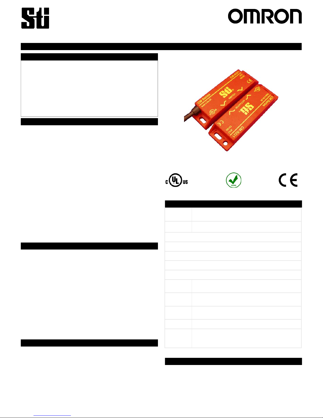
CM-S2
21 safety switches are a coded magnet safety switch
for use in machine guarding applications.
Designed for use in applications where increased security is
required, the CM-S221 has a coded magnetic actuator and
cannot be fully operated with a single magnet.
The CM-S221 switches are designed to be connected to a
safety control circuit which has less than 0.5 Amps
inrush current.
The CM-S221 is manufactured in a robust ABS housing and
fully sealed to IP67 and can be used in wet or dusty
environments.
With correct installation, the CM-S221 safety switches comply
with the guidelines given in EN1088.
CE Complies with the relevant sections of the CE
marking directive.
UL 508 Industrial Control Equipment
EUROPEAN DIRECTIVES
Machinery Directive 98/37/EC
Low Voltage Directive 73/23/EC
Electromagnetic Compatibility Directive 89/336/EC
EUROPEAN STANDARDS
EN292 Safety of Machinery
Basic concepts, general principles for design.
EN 60204 Safety of Machinery
Electrical equipment of machines.
EN 954-1 Safety of Machinery
Safety related parts of controls systems
EN 1088 Interlocking devices associated with guards.
EN
60947-5-3
Safety of Machinery
Specification for low voltage switchgear and
control gear.
Interlocke
d guards where door locking is not required.
Food and Beverage packing/filling systems
Dairy
Pharmaceutical
Paper Industry
Can Forming and Filling, (Aluminum, Steel, Plastic)
Semiconductor Manufacture/Assembly.
Description
A Declaration of Conformity can be obtained from the
Omron Scientific Technologies, Inc. web Site: www.sti.com
Whe
n the safety switch and actuator are within the specified
operating range (see table on page 3 for switching
distances), the N/C contacts will be closed and the N/O
contacts will be open.
When the actuator moves out of the operating range, the N/C
contacts will open and the N/O contacts will close. Both the
N/C and N/O contacts may be used for safety.
The CM-S221 safety switch and actuator are designed to
approach each other from most angles. When the switch is
closed the targets on the printed face of the switch must be
aligned.
Operation
Applications
Approvals
Certificate of Conformity
Safety,
Technology
& Innovation
CM Series
This information is designed to help suitably qualified
personnel install and operate Omron Scientific Technologies,
Inc. safety switch equipment.
Before using this product, read this guide thoroughly along
with any relevant European and/or National Standards e.g.
Machinery Directive 89/392/EEC and it’s Amendments,
Provision and Use of Work Equipment Regulations.
Further information can be obtained from
Omron Scientific Technologies, Inc.
KEEP THIS GUIDE FOR FUTURE REFERENCE
Operating Instructions for CM-S221 Safety Switches
Listed
Page 2
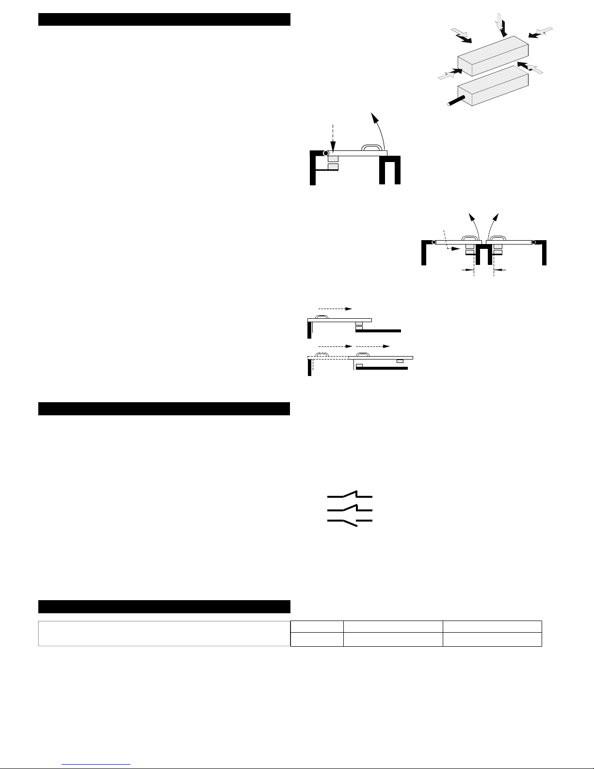
The CM-S221 safety switches can approach each other from
most angles.
When the switch is closed the targets on the printed face of
the switch must be aligned.
Mount the switch on to the machine frame and the actuator on
to the opening edge of the door. Always try to mount the
switch on non-ferrous material.
Ferrous materials may reduce the switching distance.
Use the tamper proof screws.
Do not use the safety switch as a door stop. Leave a minimum
of 50 mm between any adjacent switches.
EN 1088
Provides some mounting suggestions, see example opposite.
When fixing the safety switch to a sliding door (A), ensure that
when the door is opened (B) it is not
easily accessible, helping prevent the system being
overridden.
All contacts should be fused externally
DC
CM-S221
0.2 Amps
Mounting
Contacts & Connections
External Fusing
PRE-WIRED SWITCHES
WRONG!
Minimum 50mm
Leave a 2mm Gap
to prevent damage.
A
B
Red
Black
Green
Blue
White
Yellow
CM-S221
Page 3

Dimensions
Technical Specifications
CM-S221
RED ABS HOUSING
Dimensions in mm and [inches
in brackets]
DC Switching
Contacts Arrangements: 2 x N/C + 1 x N/O
N/C Contact Rating 24Vdc / 0.3Amp Inductive/Resistive
N/C Contact Operating Distance 7mm ON / 12mm OFF
N/C Contact Close/Drop/Bounce 3ms / 2.1ms / 0.7ms
N/O Contact Rating 24Vdc / 0.3Amp Inductive/Resistive
N/O Contact Operating Distance 8mm OFF / 10mm ON
N/O Contact Close/Drop/Bounce 0.5ms / 0.3ms / 0.7ms
External Fuse (Customer Supplied) 0.2 Amp Fast Acting
IP Rating IP67
Vibration / Shock 50—100Hz / 10g
Operating Temperature -10 to +55C
Mounting & Fixture Target to Target
Connection Pre-wired
Red ABS Resin Filled Construction
Page 4

Specification Changes
In the interest of product development, specifications are subject to
change without notice.
Document Number: 557-400 Issue.1
Note
The safety contacts of the Omron Scientific Technologies, Inc.
switches are described as normally closed (N/C)
i.e. With the guard closed, actuator in place, and the machine able
to be started.
Page 5

OMRON CANADA, INC. • HEAD OFFICE
Toronto, ON, Canada • 416.286.6465 • 866.986.6766 • www.omron247.com
OMRON ELECTRONICS DE MEXICO • HEAD OFFICE
México DF • 52.
55.59.01.43.00
• 01-800-226-6766 • mela@omron.com
OMRON ELECTRONICS DE MEXICO • SALES OFFICE
Apodaca, N.L. • 52.81.11.56.99.20 • 01-800-226-6766 • mela@omron.com
OMRON ELETRÔNICA DO BRASIL LTDA • HEAD OFFICE
São Paulo, SP, Brasil • 55.11.2101.6300 • www.omron.com.br
OMRON ARGENTINA • SALES OFFICE
Cono Sur • 54.11.4783.5300
OMRON CHILE • SALES OFFICE
Santiago • 56.9.9917.3920
OTHER OMRON LATIN AMERICA SALES
54.11.4783.5300
Authorized Distributor:
C282I-E-01 04/08
Note: Specifications are subject to change. © 2014 Omron Electronics LLC Printed in U.S.A.
Printed on recycled paper.
Automation Control Systems
• Machine Automation Controllers (MAC) • Programmable Controllers (PLC)
• Operator interfaces (HMI) • Distributed I/O • Software
D
rives & Motion Controls
• Servo & AC Drives • Motion Controllers & Encoders
Temperature & Process Controllers
• Single and Multi-loop Controllers
Sensors & Vision
• Proximity Sensors • Photoelectric Sensors • Fiber-Optic Sensors
• Amplified Photomicrosensors • Measurement Sensors
• Ultrasonic Sensors • Vision Sensors
Industrial Components
• RFID/Code Readers • Relays • Pushbuttons & Indicators
• Limit and Basic Switches • Timers • Counters • Metering Devices
• Power Supplies
S
afety
• Laser Scanners • Safety Mats • Edges and Bumpers • Programmable Safety
Controllers • Light Curtains • Safety Relays • Safety Interlock Switches
OMRON AUTOMATION AND SAFETY • THE AMERICAS HEADQUARTERS • Chicago, IL USA • 847.843.7900 • 800.556.6766 • www.omron247.com
OMRON EUROPE B.V. •
Wegalaan 67-69, NL-2132 JD, Hoofddorp, The Netherlands.
•
+31 (0) 23 568 13 00
•
www.industrial.omron.eu
 Loading...