

Cut Energy Losses
KM50
KM50
KM50
KM50
KM50
KM50
Communications Manual
Communications Manual
Communications Manual
KM
5
0-C
S
H
I
F
T
M
O
D
E
E
NT
E
R
U
P
KM
5
0-E
S
HI
F
T
M
O
D
E
E
NT
E
R
U
P
Smart Power Monitor
Smart Power Monitor
Smart Power Monitor
Cat. No. N165-E1-02

I
Introduction
Serial communications can be used for the KM50-C/-E.
This manual describes the communications functions that are supported by the KM50-C/-E.
Read and understand this manual before attempting to use communications, and use the
communications functions correctly.
Keep this manual in a safe and convenient location so that it can be used as reference whenever
required.

II
Read and Understand this Manual
Please read and understand this manual before using the product. Please consult your OMRON
representative if you have any questions or comments.
Warranty and Limitations of Liability
WARRANTY
OMRON's exclusive warranty is that the products are free from defects in materials and workmanship
for a period of one year (or other period if specified) from date of sale by OMRON.
OMRON MAKES NO WARRANTY OR REPRESENTATION, EXPRESS OR IMPLIED, REGARDING
NON-INFRINGEMENT, MERCHANTABILITY, OR FITNESS FOR PARTICULAR PURPOSE OF THE
PRODUCTS. ANY BUYER OR USER ACKNOWLEDGES THAT THE BUYER OR USER ALONE HAS
DETERMINED THAT THE PRODUCTS WILL SUITABLY MEET THE REQUIREMENTS OF THEIR
INTENDED USE. OMRON DISCLAIMS ALL OTHER WARRANTIES, EXPRESS OR IMPLIED.
LIMITATIONS OF LIABILITY
OMRON SHALL NOT BE RESPONSIBLE FOR SPECIAL, INDIRECT, OR CONSEQUENTIAL
DAMAGES, LOSS OF PROFITS OR COMMERCIAL LOSS IN ANY WAY CONNECTED WITH THE
PRODUCTS, WHETHER SUCH CLAIM IS BASED ON CONTRACT, WARRANTY, NEGLIGENCE, OR
STRICT LIABILITY.
In no event shall the responsibility of OMRON for any act exceed the individual price of the product on
which liability is asserted.
IN NO EVENT SHALL OMRON BE RESPONSIBLE FOR WARRANTY, REPAIR, OR OTHER CLAIMS
REGARDING THE PRODUCTS UNLESS OMRON'S ANALYSIS CONFIRMS THAT THE PRODUCTS
WERE PROPERLY HANDLED, STORED, INSTALLED, AND MAINTAINED AND NOT SUBJECT TO
CONTAMINATION, ABUSE, MISUSE, OR INAPPROPRIATE MODIFICATION OR REPAIR.
Application Considerations
SUITABILITY FOR USE
OMRON shall not be responsible for conformity with any standards, codes, or regulations that apply to
the combination of products in the customer's application or use of the products.
At the customer's request, OMRON will provide applicable third party certification documents
identifying ratings and limitations of use that apply to the products. This information by itself is not
sufficient for a complete determination of the suitability of the products in combination with the end
product, machine, system, or other application or use.
The following are some examples of applications for which particular attention must be given. This is
not intended to be an exhaustive list of all possible uses of the products, nor is it intended to imply that
the uses listed may be suitable for the products:
• Outdoor use, uses involving potential chemical contamination or electrical interference, or conditions
or uses not described in this manual.
• Nuclear energy control systems, combustion systems, railroad systems, aviation systems, medical
equipment, amusement machines, vehicles, safety equipment, and installations subject to separate
industry or government regulations.
• Systems, machines, and equipment that could present a risk to life or property.
Please know and observe all prohibitions of use applicable to the products.
NEVER USE THE PRODUCTS FOR AN APPLICATION INVOLVING SERIOUS RISK TO LIFE OR
PROPERTY WITHOUT ENSURING THAT THE SYSTEM AS A WHOLE HAS BEEN DESIGNED TO
ADDRESS THE RISKS, AND THAT THE OMRON PRODUCTS ARE PROPERLY RATED AND
INSTALLED FOR THE INTENDED USE WITHIN THE OVERALL EQUIPMENT OR SYSTEM.
PROGRAMMABLE PRODUCTS
OMRON shall not be responsible for the user's programming of a programmable product, or any
consequence thereof.

III
Disclaimers
CHANGE IN SPECIFICATIONS
Product specifications and accessories may be changed at any time based on improvements and other
reasons.
It is our practice to change model numbers when published ratings or features are changed, or when
significant construction changes are made. However, some specifications of the products may be
changed without any notice. When in doubt, special model numbers may be assigned to fix or establish
key specifications for your application on your request. Please consult with your OMRON
representative at any time to confirm actual specifications of purchased products.
DIMENSIONS AND WEIGHTS
Dimensions and weights are nominal and are not to be used for manufacturing purposes, even when
tolerances are shown.
PERFORMANCE DATA
Performance data given in this manual is provided as a guide for the user in determining suitability and
does not constitute a warranty. It may represent the result of OMRON's test conditions, and the users
must correlate it to actual application requirements. Actual performance is subject to the OMRON
Warranty and Limitations of Liability.
ERRORS AND OMISSIONS
The information in this document has been carefully checked and is believed to be accurate; however,
no responsibility is assumed for clerical, typographical, or proofreading errors, or omissions.
OMRON, 2010
All rights reserved. No part of this publication may be reproduced, stored in a retrieval system, or transmitted, in
any form, or by any means, mechanical, electronic, photocopying, recording, or otherwise, without the prior written
permission of OMRON.
No patent liability is assumed with respect to the use of the information contained herein. Moreover, because
OMRON is constantly striving to improve its high-quality products, the information contained in this manual is
subject to change without notice. Every precaution has been taken in the preparation of this manual. Nevertheless,
OMRON assumes no responsibility for errors or omissions. Neither is any liability assumed for damages resulting
from the use of the information contained in this publication.
IV
Safety Precautions
●Definition of Precautionary Information
The following notation is used in this manual to provide precautions that are required to
ensure safe usage of the KM50-C/-E.
The safety precautions that are provided are extremely important to safety. Always read and
heed the information provided in all safety precautions.
The following notation is used.
Meanings of Signal Words
Caution
Indicates a potentially hazardous situation which, if not
avoided, may result in minor or moderate injury, or property
damage.
●Symbols
Symbol Meaning
● Disassembly Prohibition
Indicates prohibitions when there is a possibility of injury, such as
from electric shock, as the result of disassembly.
● General Mandatory Caution
Indicates non-specific general actions that are required by the user.
● Electrical Shock Caution
Indicates the possibility of electric shock under specific conditions.
V
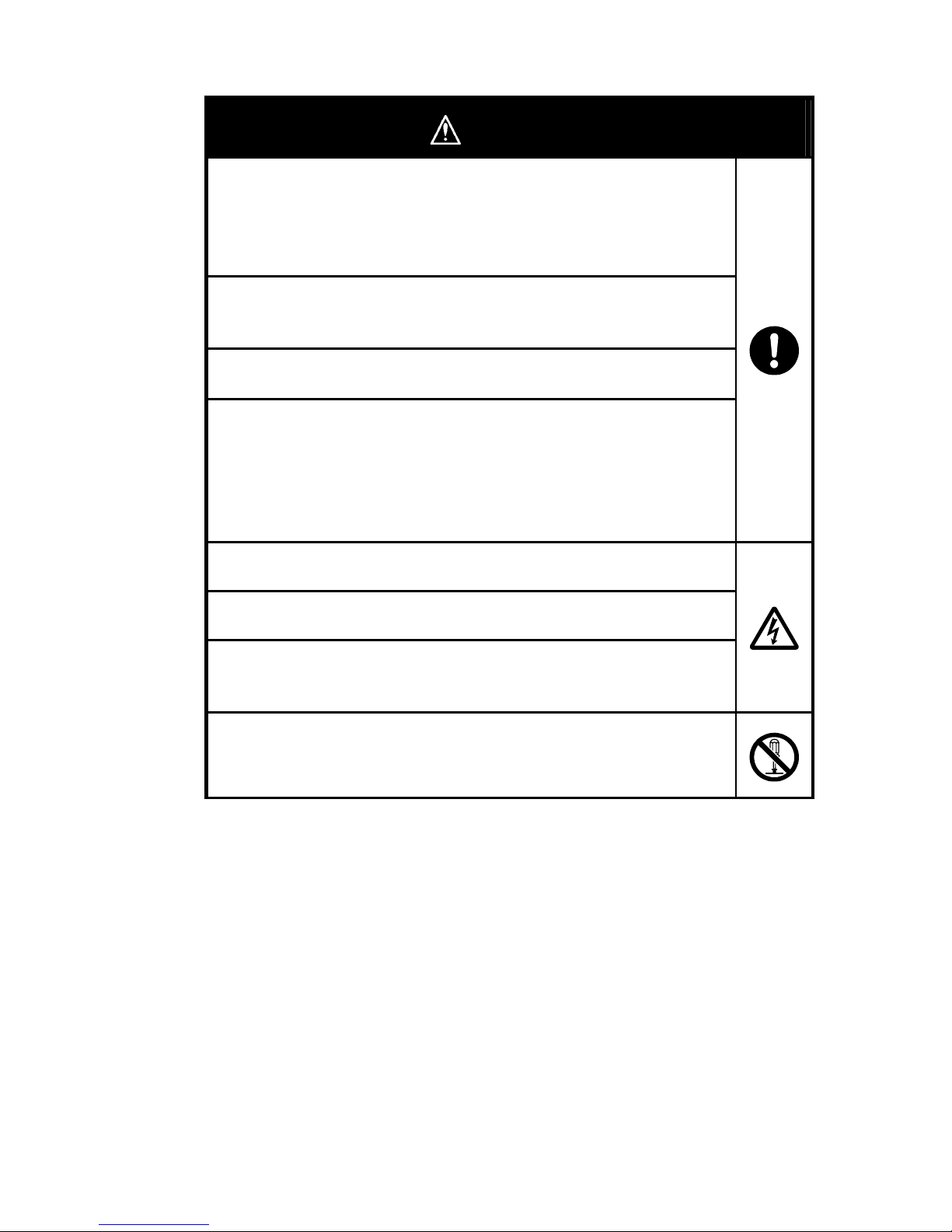
●Safety Precautions
Caution
Property damage may occasionally occur due to fire.
Tighten terminal screws to the specified tightening torque.
The recommended tightening torque is 0.69 to 0.88 N⋅m. Confirm that the
screws are straight (i.e., not at an angle) after tightening them.
Minor or moderate bodily harm or property damage may occasionally occur due
to explosion.
Do not use the product near inflammable or explosive gas.
Destruction or rupture may occasionally occur.
Make sure that the power supply voltage is within specifications.
Destruction or rupture may occasionally occur.
The voltage input circuit and CT secondary circuit are not isolated. If a Special
CT is grounded, incorrect wiring will short-circuit the voltage input and the
secondary circuit of the CT. To prevent failure, do not ground a Special CT.
The Power Monitor uses a Special CT. Correct measurements can be made
even if the CT is not grounded.
Electric shock may occasionally occur.
Always turn OFF the power supply before connecting CTs.
Electric shock may occasionally occur.
Do not touch any of the terminals while the power is being supplied.
Electric shock may occasionally occur.
The voltage input circuit and CT secondary circuit are not isolated. Do not touch
the secondary side of the Special CT.
Electrical shock, minor injury, fire, or equipment malfunction may occasionally
occur.
Do not attempt to disassemble, modify, or repair the product.

VI
Precautions for Safe Use
The following items must be observed to prevent failure to operate and malfunctions of the product
and to prevent adverse effects on performance and functions of the product.
1) Do not store, install, or use the product in the following locations.
• Locations that are greatly affected by vibration or shock
• Unstable locations
• Outdoors or locations that are subject to direct sunlight, wind, or rain
• Locations where the specified range of temperature or humidity would be exceeded
• Locations that are subject to rapid changes in temperature or humidity where
condensation or icing may occur
• Locations that are affected by static electricity or noise
• Locations that are subject to corrosive gas (particularly sulfide or ammonia gas)
• Locations that are subject to dust or iron powder
• Locations that are subject to flooding or oil
• Locations that are affected by electric or magnetic fields
• Locations that are subject to splashing brine
2) Install the product in a panel with a panel thickness of 1 to 5 mm for the KM50-C and with a
thickness of 1 to 8 mm for the KM50-E.
If a suitable panel thickness is not used or the product is installed incorrectly, the product
may come free from the mounting.
3) Do not attempt to pull the internal part of the product out of the case.
Pulling out the internal part of the product will increase the contact resistance of the
internal terminals, possibly damaging measurement accuracy.
4) Read and understand this manual before attempting to install, use, or maintain the product.
Electric shock, injury, accidents, failure, or malfunction may occur.
5) Always check the wiring and confirm that it is correct before turning ON the power supply.
Incorrect or improper wiring may result in electrical shock, injury, accidents, failure, or
malfunction.
6) Use power supplies and wires with suitable specifications for the control power supply and
the power supply for inputs and other parts of the system. Failure, burning, or electrical
shock may result.
7) Do not install the product near sources of heat, such as devices with coils or windings.
8) Check all terminal numbers before wiring.
9) Do not connect anything to unused terminals.
10) Use crimp terminals that are suitable for M3.5 screws.
11) Install the product well separated from devices with strong high-frequency noise (such as
high-frequency welders or sewing machines) or devices that generate surge.
12) To prevent inductive noise, wire the lines connected to the product separately from power
lines carrying high voltages or currents. Do not wire in parallel with or in the same cable as
power lines. Other measures for reducing noise include running lines in separate ducts
and using shields.
13) Do not touch conductive metal parts on the product or the CT terminals while power is
being supplied.
14) Do not use the product for measurement on the secondary side of an inverter.
15) Do not block the ventilation holes in or the areas around the product to ensure proper
dissipation of heat.
16) Touch grounded metal to discharge any static electricity before touching the product.
17) Do not remove the terminal blocks from the product. Doing so may cause failure or
malfunction.
18) Do not continue to use the product if the front surface peels or becomes cracked.
Water may enter the product.
19) Install and suitably label a switch or circuit breaker that complies with relevant
requirements of IEC 60947-1 and IEC 60947-3 so that the operator can immediately turn
OFF the power supply.
20) When using the product in an Overvoltage Category III environment, externally install
varistors between the power supply and voltage measurement inputs to the product.
21) Use only the Special CTs and Special CT Cable specified by OMRON.
Special CTs: KM20-CTF-5A, KM20-CTF-50A, KM20-CTF-100A,
KM20-CTF-200A, KM20-CTF-400A, and KM20-CTF-600A
Special CT Cable: KM20-CTF-CB3 (3 m)
22) The Power Monitor is a Class A product (for use in industrial environments). In residential
environment areas, it may cause radio interference. If it causes radio interference, the user
may be required to take adequate measures to reduce interference.

VII
Installation Precautions
● Maintaining Product Life
Use the KM50 within the following temperature and humidity ranges.
Temperature: −10 to 55°C (with no icing or condensation), Humidity: 25% to 85%
When the KM50 is installed in a control panel, ensure that the temperature around the KM50
(not the temperature around the panel) does not exceed 55°C.
Some of the electronic components used in the KM50 have limited service lives. The life of
these components depends on the ambient temperature. The service lives will be shorter at
higher temperatures and longer at lower temperatures. The life of the KM50 can thus be
extended by lowering the internal temperature. If more than one KM50-E Power Monitor is
mounted side by side or top to bottom, the heat generated by the Power Monitors will cause
the internal temperatures to increase, shortening the lives of the Power Monitors. To prevent
the internal temperature from increasing, forced cooling, such as fans to cool the Power
Monitors, must be considered.
● Noise Countermeasures
To prevent inductive noise, wire the lines connected to the terminal block on the KM50
separately from power lines carrying high voltages or currents. Do not wire in parallel with or
in the same cable as power lines. Other measures for reducing noise include running lines in
separate ducts and using shields.
Attach surge absorbers or noise filters to nearby equipment that generates noise (particularly
equipment with a high inductance component, such as motors, transformers, or magnetic
coils).
Install the product as far as possible away from devices with strong high-frequency noise
(such a high-frequency welders or sewing machines) or devices that generate surge.
● Waterproof Performance
The KM50 provides the following degree of protection. Any parts for which a degree of
protection is not given or for which the degree of protection is given as IP@0 are not
waterproof to any degree.
Front panel: IP66 (with enclosed Waterproof Packing), Rear case: IP20, Terminal section:
IP00

VIII
Precautions for Correct Use
1) Make sure that all parameters are set suitably for the measurement target.
2) This product is not a Special Measuring Instrument that has passed testing by a
specified body under the Measurement Act of Japan. It cannot be used to certify
power consumption under Japanese law.
3) Do not use solvents, such as paint thinners, to clean the product. Use
commercially available alcohol instead.
4) Make sure the rated voltage is reached within 2 seconds after the power is turned
ON.
Otherwise, the product may not operate correctly.
5) When discarding the product, properly dispose of it as industrial waste according
to all applicable local ordinances.
6) If a water-proof structure is required, install the enclosed Waterproof Packing.
Depending on the application environment, the Waterproof Packing can
deteriorate, shrink, or harden. We recommend that you replace it periodically.
Waterproof Packing: Y92S-29 for the KM50-C and Y92S-P5 for the KM50-E
7) Remove the protective film from the front of the product before using the product.
8) Wire the middle row (terminals 11 to 15 for the KM50-C and terminals 21 to 30 for
the KM50-E) last.
9) Provide a separate power supply for the KM50-E from the measurement voltage.
10) Reception interference may occur if the KM50 is installed near radios, televisions,
or other wireless devices.

IX
Preoperational Checks
Read the Instruction Sheet that is provided with the KM50 and check the following items.
Process Item to check Description
External
appearance
After you purchase the KM50, make sure there are no dents in the KM50 or the
packaging box.
If there is internal damage, correct measurements may not be possible depending on
the location of the damage.
Immediately
after
purchase
Model number
and specifications
Make sure that the specifications of the product you purchased match the required
specifications.
Installation Installation
location
Do not block the area around the KM50 to ensure proper dissipation of heat. Do not
block the ventilation holes in the KM50.
Provide space between the KM50 Power Monitors when installing them side by side to
prevent wiring from coming into contact with adjacent Power Monitors.
When tightening terminal screws, do not subject the terminals to excessive stress.
Tighten the terminal screws to a torque of 0.69 to 0.88 N⋅m and then make sure there
are no loose screws.
Terminal wiring
Check terminal polarity and wire all terminals correctly.
Wiring
Power supply and
voltage inputs
Wire the power supply and voltage inputs correctly. Incorrect wiring may damage
internal circuits.
Ambient
temperature
The ambient operating temperature of the KM50 is −10 to 55°C (with no condensation
or icing).
To extend the service life, install the KM50 to maintain the ambient temperature as low
as possible. If higher temperatures are unavoidable, consider using forced cooling with
a fan.
Vibration and
shock
Make sure that the vibration and shock in the installation environment do not exceed
the specified specifications.
(Install the KM50 as far away from conductors to prevent subjecting the KM50 to
vibration and shock.)
Application
environment
Foreign matter Install the KM50 so that liquids and other foreign matter will not enter it.
If sulfuric gas, chloride gas, or other corrosive gases are generated in the installation
environment, remove the source of the gas, install exhaust fans, or take other
measures to remove the gas.
Revision History
A manual revision code appears as a suffix to the catalog number on the back cover of the manual.
Cat. No. ???
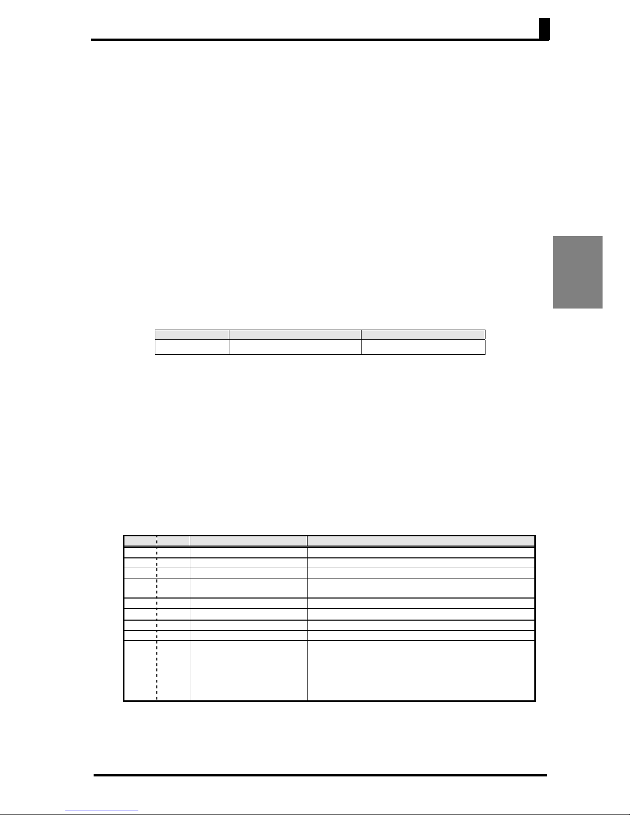
Revision code Date Revised content
A June 2010 Original production
B March 2011 Made revisions for version upgrade.

X
About this Manual
This manual is divided according to the communications protocol.
Read the section for the system that you are using.
Information is provided together for the KM50-C and KM50-E.
Information that applies only to the KM50-E is marked "KM50-E only."
There is a parameter called Instantaneous Power in the Basic Level of the Measurement
Mode. This parameter has been changed to Active Power to avoid confusion.
Related Manuals
This manual describes the communications functions that are supported by the KM50-C/-E.
Refer to the Smart Power Monitor Operation Manual (KM50-C: Cat. No. N163, KM50-E: Cat.
No. N164) for information on the functions of the Power Monitor.

XI
Table of Contents
Introduction ............................................................................................................................I
Safety Precautions..............................................................................................................IV
Precautions for Safe Use .................................................................................................... VI
Installation Precautions...................................................................................................... VII
Precautions for Correct Use.............................................................................................. VIII
Preoperational Checks........................................................................................................ IX
Revision History .................................................................................................................. IX
Table of Contents................................................................................................................ XI
Section 1 Overview ......................................................................................1-1
1. 1 Communications Protocols...................................................................................1-2
■ Introduction............................................................................................................ 1-2
■ Communications Specifications............................................................................. 1-3
■ Transmission Procedure........................................................................................ 1-3
■ Interface ................................................................................................................. 1-3
■ Wiring..................................................................................................................... 1-4
■ Communications Parameters ................................................................................ 1-4
Section 2 CompoWay/F Communications Protocol .....................................2-1
2. 1 Data Formats........................................................................................................2-2
■ Command Frame ................................................................................................... 2-2
■ BCC Calculation Example ..................................................................................... 2-3
■ Response Frame ................................................................................................... 2-3
■ Communications Data ........................................................................................... 2-4
■ End Code Examples.............................................................................................. 2-4
2. 2 Structure of Command Text .................................................................................2-5
■ PDU (Protocol Data Unit) Structure....................................................................... 2-5
■ Variable Areas and Parameter Areas.................................................................... 2-5
■ Area Definitions ..................................................................................................... 2-6
■ Type Codes ........................................................................................................... 2-6
■ Addresses.............................................................................................................. 2-7
■ Number of Elements.............................................................................................. 2-7
■ List of Services ...................................................................................................... 2-7
2. 3 Detailed Descriptions of Services.........................................................................2-8
■ Read Variable Area ............................................................................................... 2-8
■ Read Parameter Area.......................................................................................... 2-10
■ Write Parameter Area .......................................................................................... 2-12
■ Read Controller Attributes ................................................................................... 2-14
■ Read Controller Status ........................................................................................ 2-15
■ Read Time Data................................................................................................... 2-16
■ Write Time Data ................................................................................................... 2-17
■ Echoback Test..................................................................................................... 2-18

XII
■
Operation Command ........................................................................................... 2-19
2.4 Response Codes................................................................................................2-21
Section 3 CompoWay/F Communications Data.......................................... 3-1
3. 1 Variable Area .......................................................................................................3-3
3. 2 Status Information .............................................................................................. 3-44
3. 3 Parameter Area..................................................................................................3-45
Section 4 Modbus Communications Protocol ............................................. 4-1
4. 1 Data Formats .......................................................................................................4-2
■ Command Frames ................................................................................................. 4-2
■ Response Frames ................................................................................................. 4-3
■ Error Codes............................................................................................................ 4-4
4. 2 Function List......................................................................................................... 4-5
4. 3 Variable Area .......................................................................................................4-6
■ Addresses.............................................................................................................. 4-6
■ Number of Elements .............................................................................................. 4-6
■ Set Values.............................................................................................................. 4-6
4. 4 Detailed Descriptions of Services......................................................................... 4-7
■ Read Variable Area ............................................................................................... 4-7
■ Write Variable Area................................................................................................ 4-9
■ Operation Command ........................................................................................... 4-11
■ Echoback Test ..................................................................................................... 4-13
Section 5 Modbus Communications Data ................................................... 5-1
5. 1 Variable Area .......................................................................................................5-3
5. 2 Status Information .............................................................................................. 5-40
5. 3 Variable Area Setting Ranges ............................................................................ 5-41
Appendicies ................................................................................................ A-1
ASCII Table ...................................................................................................................... A-2
Troubleshooting ................................................................................................................ A-3
Index

1-1
Section 1 Overview
1. 1
Communications Protocols ................................................................... 1-2
■ Introduction ........................................................................................................ 1-2
■ Communications Specifications ........................................................................ 1-3
■ Transmission Procedure.................................................................................... 1-3
■ Interface ............................................................................................................. 1-3
■ Wiring .............................................................................................................. 1-4
■ Communications Parameters ............................................................................ 1-4

Section 1 Overview
1-2
Overview
1. 1 Communications Protocols
■ Introduction
Communications can be used to monitor measurement data, collect measurement data, and
change settings for the KM50-C/-E from a host (e.g., computer). A program must be created
for the host. This manual describes communications from the viewpoint of the host.
CompoWay/F is a general-purpose OMRON serial communications protocol. The CompoWay/F
protocol supports standard frame formats and FINS*-compliant commands, which are widely used
by OMRON Programmable Controllers and other devices, for easy communications between a
host and components.
* FINS (Factory Interface Network Service) is a protocol for messaging between controllers on
OMRON FA networks.
Modbus is a communications protocol that complies with the RTU Mode of the Modbus protocol
(PI-MBUS-300 Rev. J) from Schneider Electric. Modbus is a registered trademark of Schneider
Electric. It supports the same functions as those provided by CompoWay/F for reading variable
areas, writing variable areas, executing operation commands, and executing echoback testing.
The following communications functions are supported by the KM50-C/-E.
• Reading/writing parameters
• Operation commands
• Changing the operating mode
The following conditions apply to the communications functions.
Writing parameters is possible only in one of the Setting Modes.
Changes to parameters that are made in a Setting Mode are enabled by changing to
Measurement Mode.
1. 1 Communications Protocols
1-3
Overview
■ Communications Specifications
Communications
protocol
CompoWay/F Modbus (RTU)
Transmission path
connections
Multidrop
Communications
method
Two-wire, half-duplex
Sync method Start-stop
Baud rate
1.2, 4.8, 9.6, 19.2, 38.4 kbps
Transmission code ASCII Binary
Data length 7 or 8 bits Always 8 bits (no setting available)
Stop bits 1 or 2 bits
Automatically set according to the setting of
the vertical parity (no setting available).
No vertical parity: 2 bits
Odd or even vertical parity: 1 bit
Error detection
Vertical parity (even, odd, or none)
BCC (block check character)
Vertical parity (even, odd, or none)
CRC-16 (Cyclical Redundancy Check)
Flow control None
Interface RS-485
Retry function None
Communications
response
transmission wait time
0 to 99 ms, default: 20 ms
* Default settings are given above with a gray background.
* CompoWay/F is the default communications protocol.
* The baud rate, data length, number of stop bits, and vertical parity can all be set individually.
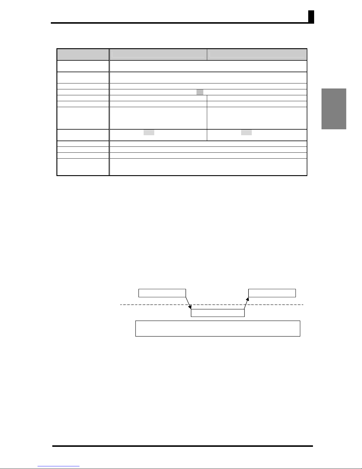
■ Transmission Procedure
The host (e.g., computer) sends a command frame. The KM50-C/-E returns a response according
to the contents of the command. One response frame is always returned for each command frame.
The operation of command frames and response frames is illustrated below.
■ Interface
The host must perform communications that comply with an RS-485 interface.
Use the K3SC to convert between the RS-485 and an RS-232C interface.
KM50-C/E
Host (e.g., computer)
Command frame
Command
frame
Response frame
Allow a period of 2 ms or longer at the computer between receiving a
response and sending the next command.

Section 1 Overview
1-4
Overview
■ Wiring
● RS-485
• The connection configuration is 1:1 or 1:N. For a 1:N configuration, up to 31 KM50-C/-E nodes
can be connected for CompoWay/F and up to 99 KM50-C/-E nodes can be connected for
Modbus.
The host (e.g., computer) is not counted as a node for these limits.
• The maximum total cable length is 500 m.
• Use shielded twisted-pair cables with wires of AWG24 to AWG14 (cross-sectional areas of 0.205
to 2.081 mm
2
).
• Terminating resistance must be connected to the nodes at the ends of the transmission path
(including the host).
Use a terminating resistance of 120 Ω (1/2 W) at each end.
The communications specifications of the host must match those of the KM50-C/-E. For a 1:N
configuration, the communications specifications of all nodes must match. Each node, however,
must have a unique communications unit number. This manual describes how to set the
communications specifications for the KM50-C/-E. Refer to user documentation for your host to set
the host communications specifications.
■ Communications Parameters
The communications specifications for the KM50-C/-E are set in Communications Setting Mode.
The following table lists the communications parameters and set values.
Parameter Set values Default setting
Communications Protocol CompoWay/F or Modbus CompoWay/F
Unit Number 00 to 99 01
Baud Rate 1.2, 4.8, 9.6, 19.2, or 38. 4 (kbits/s) 9.6 (kbits/s)
Data Length 7 or 8 (bits) 7 (bits)
Stop Bits 1 or 2 (bits) 2 (bits)
Vertical Parity Even, odd, or none Even
Transmission Wait Time 00 to 99 (ms) 20 (ms)

1. 1 Communications Protocols
1-5
Overview
● Communications Parameters
Changes to the settings are enabled when you return to Measurement Mode.
• Protocol Selection (80.psl)
Select the communications protocol. You can select either CompoWay/F or Modbus.
If Modbus is selected, the data length will always be 8 bits and the number of stop bits will be set
automatically according to the vertical parity.
No vertical parity: 2 bits
Odd or even vertical parity: 1 bit
• Communications Unit Number (81.u.no)
The communications unit number is used to differentiate between different nodes when
communicating from the host. The communications unit number can be set to integers between
0 to 99.
The default setting is 1. If the same communications unit number is set for more than one node,
normal operation will not be possible.
• Baud Rate (82.bps)
Set the baud rate for communications with the host. The baud rate settings are as follows:
1.2 (1.2kbps), 2.4 (2.4kbps), 4.8 (4.8kbps), 9.6 (9.6kbps), 19.2 (19.2kbps), or 38.4 (38.4kbps)
• Data Length (83.len)
Set the communications data bit length. The bit length can be 7 bits or 8 bits.
• Stop Bits (84.sbt)
Set the number of communications stop bits. Either one or two stop bits can be set.
• Vertical Parity (85.prt)
Select the vertical parity. The parity can be set to none, even, or odd.
• Transmission Wait Time (86.sdw)
The transmission wait time can be set to between 0 and 99 ms in 1-ms increments. The default
setting is 20 ms.

Section 1 Overview
1-6
Overview

2-1
Section 2 CompoWay/F
Communications
Protocol
This section describes performing communications using the CompoWay/F protocol.
2. 1 Data Formats ................................................................................ 2-2
■ Command Frame ..................................................................................... 2-2
■ BCC Calculation Example........................................................................ 2-3
■ Response Frame...................................................................................... 2-3
■ Communications Data.............................................................................. 2-4
■ End Code Examples ................................................................................ 2-4
2. 2 Structure of Command Text.......................................................... 2-5
■ PDU (Protocol Data Unit) Structure ......................................................... 2-5
■ Variable Areas and Parameter Areas ...................................................... 2-5
■ Area Definitions........................................................................................ 2-6
■ Type Codes .............................................................................................. 2-6
■ Addresses ................................................................................................ 2-7
■ Number of Elements ................................................................................ 2-7
■ List of Services......................................................................................... 2-7
2. 3 Detailed Descriptions of Services ................................................. 2-8
■ Read Variable Area .................................................................................. 2-8
■ Read Parameter Area ............................................................................ 2-10
■ Write Parameter Area ............................................................................ 2-12
■ Read Controller Attributes ...................................................................... 2-14
■ Read Controller Status ........................................................................... 2-15
■ Read Time Data ..................................................................................... 2-16
■ Write Time Data ..................................................................................... 2-17
■ Echoback Test ....................................................................................... 2-18
■ Operation Command .............................................................................. 2-19
2.4 Response Codes......................................................................... 2-21

Section 2 CompoWay/F Communications Protocol
2-2
CompoWay/F
Communications
Protocol
2. 1 Data Formats
In this manual, hexadecimal numbers are indicated by "hex" placed after the number. All other numbers
indicate ASCII characters. The numbers below the various parts of the frame are the number of bytes.
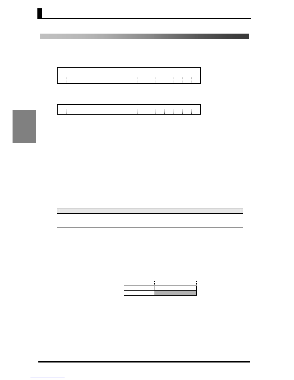
■ Command Frame
Text
Node No. Sub-address SID Command text BCC
STX 0 0 0 ETX
1 2 2 1 1 1
BCC calculation range
STX
This code (02 hex) indicates the beginning of a communications frame.
Always place this code in the first byte.
If the STX is received during data reception, reception will be started over
from where the STX is received.
Node No.
• The node number indicates the destination of the frame.
• For the KM50-C/-E, specify the communications unit number.
• Either a number from 00 to 99 or "XX" (uppercase) can be set for the node
number.
• "XX" specifies broadcasting. Responses are not returned for broadcast
command frames.
• Responses are also not returned if any other node numbers are specified.
Sub-address This is not used by the KM50-C/-E. Always set it to 00.
SID (service ID) This is not used by the KM50-C/-E. Always set it to 00.
Command text This is the command text. Refer to 2.2 Structure of Command Text for details.
ETX This code (03 hex) indicates the end of a communications frame.
BCC
This is the block check character.
The BCC is found by taking the exclusive OR of the bytes from the node
number through the ETX.

2. 1 Data Formats
2-3
CompoWay/F
Communications
Protocol
■ BCC Calculation Example
The BCC (Block Check Character) is determined by finding the exclusive OR of the bytes from the
node number through the ETX. The 8-bit result is written to the BCC byte at the end of the frame.
■ Response Frame
Node No. Sub-address End code Command text BCC
STX ETX
1 2 2 2 1 1
End code Name Description
Error
detection
priority
00 Normal completion The command ended normally without error. None
0F
FINS command
error
The specified FINS command could not be executed.
The FINS response code should indicate why the command
could not be executed.
7
10 Parity error
The sum total of "1" bits in the received data does not match
the set value of the communications parity bit.
2
11 Framing error The stop bit is 0. 1
12 Overrun error
An attempt was made to transfer new data when the
reception data buffer was already full.
3
13 BCC error
The calculated BCC value is different from the received BCC
value.
6
14 Format error
• The command text contains characters other than 0 to 9
and A to F. This error does not apply to echoback tests.
(Refer to Echoback Test for details.)
• There was no SID and command text. There was no
command text.
• The MRC/SRC was not included in command text.
5
18
Frame length
error
The received frame exceeds the specified (supported)
number of bytes.
4
• An end code is returned for each command frame received by the addressed node.
• No response will be returned unless the command frame contains all elements up to the ETX
and BCC.
• The "error detection priority" indicates the priority when two or more errors occur simultaneously.

Section 2 CompoWay/F Communications Protocol
2-4
CompoWay/F
Communications
Protocol
■ Communications Data
Communications
protocol
Set value
(monitor value)
Negative values Decimal points
CompoWay/F 8-digit hexadecimal Two's complement
Data is converted to hexadecimal without the
decimal point.
Example: 105.0 → 1050 → 0000 041A hex
■ End Code Examples
The following examples show the end codes that are returned when the command could not be
processed normally.
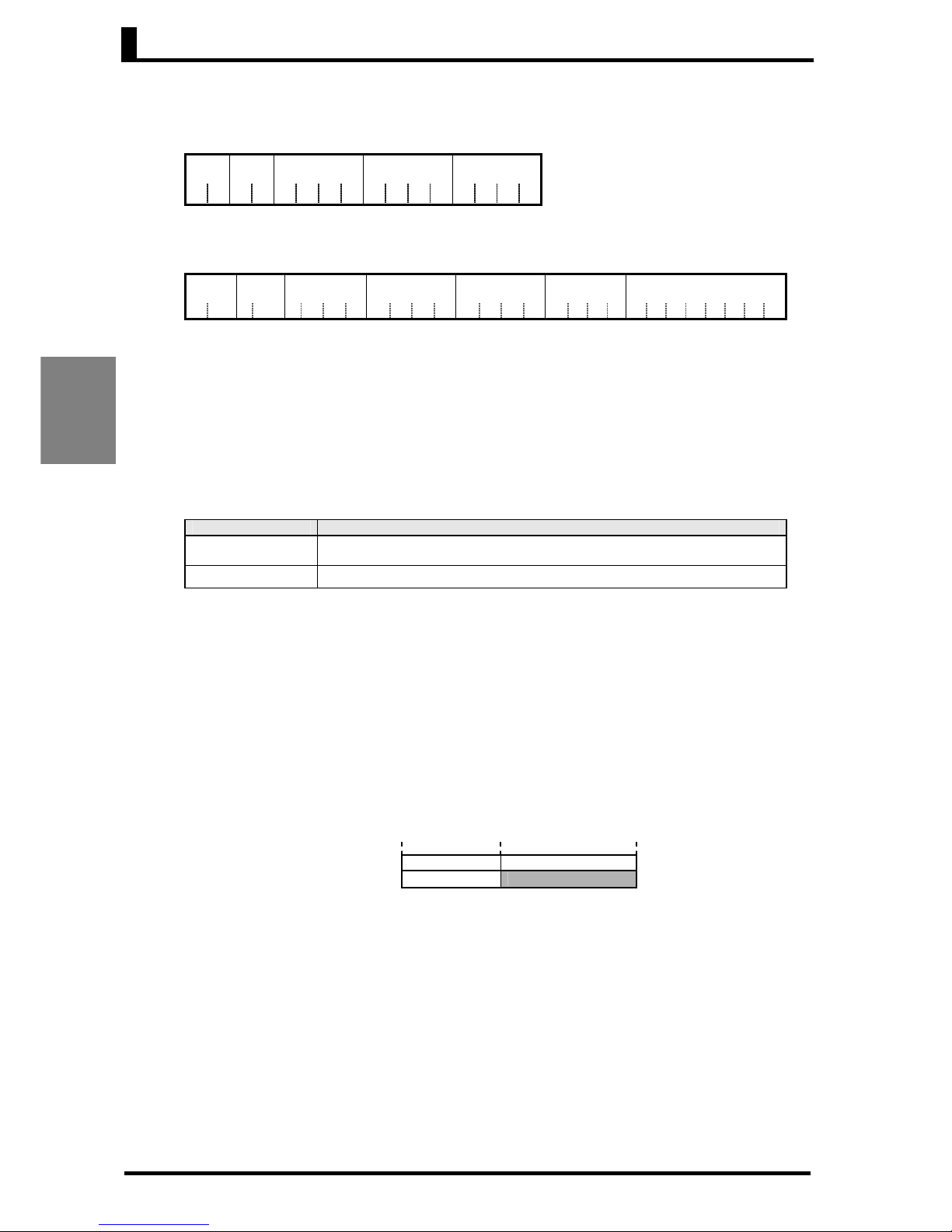
Example 1: Sub-address Less Than Two Characters, No SID, and No Command Text
• Command
Node No. BCC
STX ETX
One sub-address character is missing.
• Response
Node No. Sub-address End code BCC
STX 0 0 1 4 ETX
The sub-address is 00 and the end code is 14 (format error).
Example 2: No Command Text
• Command
Node No. Sub-address SID BCC
STX 0 0 0 ETX
•
Response
Node No. Sub-address End code BCC
STX 0 0 1 4 ETX
The end code is 14 (format error).
Example 3: No Node Number
• Command
BCC
STX ETX
One node number character is missing.
• Response
No response is returned.

2. 2 Structure of Command Text
2-5
CompoWay/F
Communications
Protocol
MRC SRC MRES SRES
2. 2 Structure of Command Text
■ PDU (Protocol Data Unit) Structure
An MRC (Main Request Code) and SRC (Sub-Request Code) followed by the various required
data are sent as the command text.
• Service Request PDU
The MRES (Main Response Code) and SRES (Sub-Response Code) are sent in the
response frame following the above MRC/SRC.
• Service Response PDU (Normal Response)
If the specified command text could not be executed, the service response PDU will
contain only the MRC/SRC and MRES/SRES.
■ Variable Areas and Parameter Areas
The KM50-C/-E use two areas for data communications. The variable area is accessed to read
measurement values.
The variable area is separated into areas for the three types of measurement values,
instantaneous, maximum, and minimum, and an area to read the measurement log. The
addresses of the variables and measurement values are specified to read the measurement
values and measurement log.
The parameter area is used to read and write the current parameter settings. The address of the
parameter to read or write is specified to monitor or change the set value.
Tables of the variable area and parameter area are provided in Section 3 CompoWay/F
Communications Data.
Other commands do not use the variable and parameter areas.
Data
MR
C SRC
Data
Section 2 CompoWay/F Communications Protocol
2-6
CompoWay/F
Communications
Protocol
■ Area Definitions
There are two areas: the variable area and the parameter area.
The codes for each area are defined as follows:
• Variable Area
MSB LSB
• Parameter Area
MSB LSB
The variable type is converted to 2-byte ASCII or the parameter type is converted to 4-byte ASCII
and loaded to the frame.
■ Type Codes
The type codes for the variable area are given in the following table.
Variable type Contents Remarks
C0
Instantaneous measurement values
*
1
C2
Maximum measurement values
*
1
C3
Minimum measurement values
*
1
C8
Instantaneous measurement values
*
2
CA
Maximum measurement values
*
2
CB
Minimum measurement values
*
2
Log for current day
D0
Every 5-minute
period
*
4
D1
Every 5 minutes
*
4
D4
Total power consumption log
Every hour
*
4
Log for the last day
D5 Total power consumption log
Every day
*
4
D6 Pulse input ON times
Every day
*
4
D7
Specific power consumption
log
Every day
*
4
D8 Pulse count log
Every day
*
4
Log for the last 8 days
DB Total power consumption log
Every month
*
4
For the last 13 months
DC
*
3
Total operating power
DD
*
3
Total standby power
DE
*
3
Total stopped power
Refer to note.
*
4
5-minute-period data for up to one day
ago
Total power consumptions and times,
and ratios, for every day for last 8
days
E0 Maximum value log
Every day
*
4
E1 Minimum value log
Every day
*
4
Log for the last 8 days
E2 Alarm history Log of the last 10 alarms
Access size
11: Double word
Variable type (1 byte)
Type code
Access size
11: Double word
Parameter type (2 bytes)
Type code
2. 2 Structure of Command Text
2-7
CompoWay/F
Communications
Protocol
*1 The command system is adjusted to that of the KM20-B40 and KM100. Using these
variable types is convenient when adding to an existing KM-series system.
*2 This is the command system for the KM50-C/-E.
The read commands are the same as those indicated with "*1," but the items were
reordered to make reading easier. Using these variable types is convenient for new
systems.
*3 These type codes are used only for the KM50-E.
*4 The time units for the measurement values are as follows:
Every 5-minute period: Values measure over a 5-minute period, e.g., 00:05 to 00:10.
Every 5 minutes: Values measured every 5 minutes for 2 days.
(Total from when the power is turned ON or the Power Monitor is reset.)
Every hour: Values measured over a 1-hour period.
Every day: Values measured over a 1-day period.
Every month: Values measured over a 1-month period.
*5 The history of alarms that occurred in the past is not saved when power is interrupted.
Only alarms that occur after power supply is turned ON are in the history.
The type codes for the parameter area are given in the following table.
Parameter type Contents Remarks
C000 Setting parameters
■ Addresses
An address is appended to each variable type. Express addresses in 2-byte hexadecimal and
append them for the specified access size.
■ Number of Elements
The number of elements is expressed in 2-byte hexadecimal.
The specification range for the number of elements depends on the command. Refer to the
descriptions of individual services for details.
■ List of Services
MRC SRC Name of service Processing
01 01 Read Variable Area This service reads from the variable area.
02 01 Read Parameter Area This service reads from the parameter area.
02 02 Write Parameter Area This service writes to the parameter area.
05 03 Read Controller Attributes This service reads the model number and communications
buffer size.
06 01 Read Controller Status This service reads the operating status.
07 01 Read Time Data This service reads the time data.
07 02 Write Time Data This service writes the time data.
08 01 Echoback Test This service performs an echoback test.
30 05 Operation Command This service performs the following operations according to
the command.
• Reset Total Power Consumption
• Reset Maximum/Minimum
• Reset Software
• Initialize Settings (restore defaults)
* Services will not be accepted and responses will not be returned while the Power Monitor is
starting (i.e., from when the wait display appears at startup until the instantaneous power is
displayed).
Section 2 CompoWay/F Communications Protocol
2-8
CompoWay/F
Communications
Protocol
2. 3 Detailed Descriptions of Services
■ Read Variable Area
This service reads from the variable area.
• Service Request PDU
MRC SRC
Variable
type
Read start address Bit
position
No. of elements
0 1 0 1 0 0
2 2 2 4 2 4
(Numbers below the frame are the number of bytes.)
• Service Response PDU
MRC SRC Response code Read data (for the number of elements)
0 1 0 1
2 2 4
8
× n (n = 0 to 11)
(1) Variable Type and Read Start Address
For details on variable types and read start addresses, refer to SECTION 3 CompoWay/F
Communications Data.
(2) Bit Position
Bit access is not supported by the KM50-C.
Always use 00.
(3) Number of Elements
Specify the number of variables to read.
No. of elements Processing
0000
The read operation is not performed (i.e., read data is not appended to the service
response PDU), and processing ends in a normal completion.
0001 to 000B Up to 11 elements (0B hex) is read, and processing ends in a normal completion.
* If the read start address is in the variable area and the read end address (read start
address + number of elements) exceeds the last address in the variable area, the data to
the end of the variable area will be read and processing will end in a normal completion.
Example 1: The last address is specified as the read start address and two elements is
specified.
Address Variable area
**** ********
Read start address →
****
********
←Last address
Read end address →
Only the value at the last address will be read.

2. 3 Detailed Descriptions of Services
2-9
CompoWay/F
Communications
Protocol
Example 2: One less than the last address is specified as the read start address and
13 elements is specified (0D hex).
Address Variable area
Read start address→
**** ********
**** ********
←Last address
Read end address→
The number of elements exceeds the specification range, so only the data to the last
address in the area is read.
(4) Response Code
• Normal Completion
Response code Name Description
0000 Normal completion No errors were detected.
• Error Completion
Response code Error name Cause
1001 Command too long The command is too long.
1002 Command too short The command is too short.
1101 Area type error The variable type is wrong.
1103
Start address
out-of-range error
The read start address is out of
range.
110B Response too long
The number of elements exceeds
the maximum value.
1100 Parameter error Bit position is not 00.
● Communications Example for Read Variable Area
Instantaneous voltage 1 was measured at 101.2 V and instantaneous voltage 2 was measured at
102.3 V. Here, these two values are read with one command.
Service Request PDU
0 1
0 1 C 0 0 0 0 4 0 0 0 0 0 2
Service Response PDU
0 1
0 1 0 0 0 0 0 0 0 0 0 3 F 4 0 0 0 0 0 3 F F
The KM50 returns measurement values converted to hexadecimal without decimal points.
0000 03F4 hex = 1012 decimal
Section 3 CompoWay/F Communications Data specifies one place below the decimal point for
the set value/monitor value for instantaneous voltage 1, so the value is 101.2 V. This also applies
to instantaneous voltage 2, i.e., 0000 03FF hex = 1023 decimal, or 102.3 V.
MRC SRC
Var iable
type
Read start
address
No. of elements (Reads two measurement values.)
MRC
SRC
Response
code
Voltage 1
Bit
position
Voltage 2
Section 2 CompoWay/F Communications Protocol
2-10
CompoWay/F
Communications
Protocol
■ Read Parameter Area
This service reads from the parameter area.
• Service Request PDU
MRC SRC Parameter
type
Read start
address
No. of
elements
0 2 0 1
2 2 4 4 4
(Numbers below the frame are the number of bytes.)
• Service Response PDU
MRC SRC Response
code
Parameter
type
Read start
address
No. of
elements
Read data (for the number
of elements)
0 2 0 1
2 2 4 4 4 4 8 × n (n: 0 to 10)
(1) Parameter Type and Read Start Address
For details on parameter types and read start addresses, refer to SECTION 3 CompoWay/F
Communications Data.
(2) Number of Elements
Specify the number of parameters to read.
No. of elements Processing
8000
The read operation is not performed (i.e., read data is not appended to the service
response PDU), and processing ends in a normal completion.
8001 to 800A Up to 10 elements (0A hex) is read, and processing ends in a normal completion.
* Setting range for the number of elements (8001 to 800A): Always set the MSB of the
number of elements to 1.
* If the read start address is in the parameter area and the read end address (read start
address + number of elements) exceeds the last address in the parameter area, the data
to the end of the parameter area will be read and processing will end in a normal
completion.
Example 1: The last address is specified as the read start address and two elements is
specified.
Address Parameter area
**** ********
Read start address →
****
********
←Last address
Read end address →
Only the value at the last address will be read.
2. 3 Detailed Descriptions of Services
2-11
CompoWay/F
Communications
Protocol
Example 2: One less than the last address is specified as the read start address and 13
elements is specified (0D hex).
Address Parameter Area
Read start address→
**** ********
**** ********
←Last address
Read end address→
The number of elements exceeds the specification range, so only the data to the last
address in the area is read.
(3) Response code
• Normal Completion
Response code Name Description
0000 Normal completion No errors were detected.
• Error Completion
Response code Error name Cause
1001 Command too long The command is too long.
1002 Command too short The command is too short.
1101 Area type error
The area type (variable or parameter) is
wrong.
1103
Start address out-of-range
error
The read start address is out of range.
110B Response too long
The number of elements exceeds the
maximum value.
1100 Parameter error Bit position is not 00.
● Communications Example for Read Parameter Area
The CT ratio is set to 150:5 (for a 5-A CT) and the low cut current is set to 1.0%. Here, these two
settings are read with one command.
Service Request PDU
0 2 0 1 C 0 0 0 0 0 0 4 8 0 0 2
Service Response PDU
0 2
0 1 0 0 0 0 C 0 0 0 0 0 0 4 8 0 0 2
0 0 0 0 0 0 9 6
0 0 0 0 0 0 0 A
Section 3 CompoWay/F Communications Data specifies 0000 0001 to 0000 270F hex for the set
value/monitor value for the rated primary current. A value of 96 hex is 150 decimal, so the current
is 150 A.
Section 3 CompoWay/F Communications Data specifies 0000 0001 to 0000 00C7 hex for the
low-cut current. A value of A hex is 10 decimal, so the low-cut current is 1.0% (there is always one
place below the decimal point).
MRC
SRC Parameter
type
Read start
address
No. of elements
(Reads two parameter values.)
MRC
SRC
Response
code
Parameter
type
Read start
address
No. of
elements
Rated Primary Current Low-cut Current
 Loading...