

Page 1
1
Overview
2
Nomenclature and
Functions
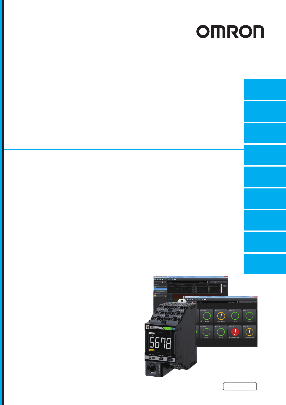
Motor Condition
Monitoring Device
User's Manual
K6CM
Mechanism of Measuring and
Monitoring of the K6CM Devices
4
3
Installation and Wiring
5
Setting with the Motor
condition monitoring Tool
6
Internal Data List of
the K6CM Devices
7
Motor Monitoring and Operation
with the K6CM Devices and the
Motor condition monitoring Tool
8
Monitoring and Setting
with the EtherNet/IP
9
Trouble shooting
N219-E1-06
Page 2

NOTE
All rights reserved. No part of this publication may be reproduced, stored in a retrieval system, or transmitted, in
any form, or by any means, mechanical, electronic, photocopying, recording, or otherwise, without the prior
written permission of OMRON.
No patent liability is assumed with respect to the use of the information contained herein. Moreover, because
OMRON is constantly striving to improve its high-quality products, the information contained in this manual is
subject to change without notice. Every precaution has been taken in the preparation of this manual. Nevertheless, OMRON assumes no responsibility for errors or omissions. Neither is any liability assumed for damages
resulting from the use of the information contained in this publication.
Trademarks
• Microsoft, Windows is either registered trademarks or trademarks of Microsoft Corporation in the United States
and other countries.
• ODVA, CIP, CompoNet, DeviceNet, and EtherNet/IP are trademarks of ODVA.
Other company names and product names in this document are the trademarks or registered trademarks of their
respective companies.
Copyrights
Microsoft product screen shots reprinted with permission from Microsoft Corporation.
Page 3

Preface
Thank you for purchasing K6CM Motor Condition Monitoring Devices.
This manual describes how to use the K6CM. Read this manual thoroughly and be sure you understand it before attempting to use the K6CM correctly according to the information provided. Keep this
manual in a safe place for easy reference.
PDF version of this manual can be downloaded from the OMRON website.
(http://www.omron.co.jp)
Preface
K6CM Motor Condition Monitoring Device User’s Manual (N219)
1
Page 4

Terms and Conditions Agreement
Terms and Conditions Agreement
Warranty, Limitations of Liability
Warranties
z Exclusive Warranty
Omron’s exclusive warranty is that the Products will be free from defects in materials and workmanship for a period of twelve months from the date of sale by Omron (or such other period expressed in
writing by Omron). Omron disclaims all other warranties, express or implied.
z Limitations
OMRON MAKES NO WARRANTY OR REPRESENTATION, EXPRESS OR IMPLIED, ABOUT
NON-INFRINGEMENT, MERCHANTABILITY OR FITNESS FOR A PARTICULAR PURPOSE OF
THE PRODUCTS. BUYER ACKNOWLEDGES THAT IT ALONE HAS DETERMINED THAT THE
PRODUCTS WILL SUITABLY MEET THE REQUIREMENTS OF THEIR INTENDED USE.
Omron further disclaims all warranties and responsibility of any type for claims or expenses based
on infringement by the Products or otherwise of any intellectual property right.
z Buyer Remedy
Omron’s sole obligation hereunder shall be, at Omron’s election, to (i) replace (in the form originally
shipped with Buyer responsible for labor charges for removal or replacement thereof) the non-complying Product, (ii) repair the non-complying Product, or (iii) repay or credit Buyer an amount equal
to the purchase price of the non-complying Product; provided that in no event shall Omron be
responsible for warranty, repair, indemnity or any other claims or expenses regarding the Products
unless Omron’s analysis confirms that the Products were properly handled, stored, installed and
maintained and not subject to contamination, abuse, misuse or inappropriate modification. Return of
any Products by Buyer must be approved in writing by Omron before shipment. Omron Companies
shall not be liable for the suitability or unsuitability or the results from the use of Products in combination with any electrical or electronic components, circuits, system assemblies or any other materials or substances or environments. Any advice, recommendations or information given orally or in
writing, are not to be construed as an amendment or addition to the above warranty.
See http://www.omron.com/global/ or contact your Omron representative for published information.
Limitation on Liability; Etc
OMRON COMPANIES SHALL NOT BE LIABLE FOR SPECIAL, INDIRECT, INCIDENTAL, OR CONSEQUENTIAL DAMAGES, LOSS OF PROFITS OR PRODUCTION OR COMMERCIAL LOSS IN ANY
WAY CONNECTED WITH THE PRODUCTS, WHETHER SUCH CLAIM IS BASED IN CONTRACT,
WARRANTY, NEGLIGENCE OR STRICT LIABILITY.
Further, in no event shall liability of Omron Companies exceed the individual price of the Product on
which liability is asserted.
2
K6CM Motor Condition Monitoring Device User’s Manual (N219)
Page 5

Application Considerations
Suitability of Use
Omron Companies shall not be responsible for conformity with any standards, codes or regulations
which apply to the combination of the Product in the Buyer’s application or use of the Product. At
Buyer’s request, Omron will provide applicable third party certification documents identifying ratings
and limitations of use which apply to the Product. This information by itself is not sufficient for a complete determination of the suitability of the Product in combination with the end product, machine, system, or other application or use. Buyer shall be solely responsible for determining appropriateness of
the particular Product with respect to Buyer’s application, product or system. Buyer shall take application responsibility in all cases.
NEVER USE THE PRODUCT FOR AN APPLICATION INVOLVING SERIOUS RISK TO LIFE OR
PROPERTY OR IN LARGE QUANTITIES WITHOUT ENSURING THAT THE SYSTEM AS A WHOLE
HAS BEEN DESIGNED TO ADDRESS THE RISKS, AND THAT THE OMRON PRODUCT(S) IS
PROPERLY RATED AND INSTALLED FOR THE INTENDED USE WITHIN THE OVERALL EQUIPMENT OR SYSTEM.
Terms and Conditions Agreement
Programmable Products
Omron Companies shall not be responsible for the user’s programming of a programmable Product, or
any consequence thereof.
Disclaimers
Performance Data
Data presented in Omron Company websites, catalogs and other materials is provided as a guide for
the user in determining suitability and does not constitute a warranty. It may represent the result of
Omron’s test conditions, and the user must correlate it to actual application requirements. Actual performance is subject to the Omron’s Warranty and Limitations of Liability.
Change in Specifications
Product specifications and accessories may be changed at any time based on improvements and other
reasons. It is our practice to change part numbers when published ratings or features are changed, or
when significant construction changes are made. However, some specifications of the Product may be
changed without any notice. When in doubt, special part numbers may be assigned to fix or establish
key specifications for your application. Please consult with your Omron’s representative at any time to
confirm actual specifications of purchased Product.
Errors and Omissions
Information presented by Omron Companies has been checked and is believed to be accurate; however, no responsibility is assumed for clerical, typographical or proofreading errors or omissions.
K6CM Motor Condition Monitoring Device User’s Manual (N219)
3
Page 6

Safety Precautions
Safety Precautions
Definition of Precautionary Information
The following notation is used in this manual to provide precautions required to ensure safe usage of
the K6CM Motor Condition Monitoring Devices.
The safety precautions that are provided are extremely important to safety. Always read and heed the
information provided in all safety precautions.
Symbols
The following notation is used.
CAUTION
Indicates a potentially hazardous situation which, if not avoided,
may result in minor or moderate injury or in property damage.
Symbol Meaning
• General Caution
Indicates non-specific general cautions, warnings, and dangers.
Caution
Prohibition
Mandatory
Caution
• Electrical Shock Caution
Indicates possibility of electric shock under specific conditions.
• General Prohibition
Indicates non-specific general prohibitions.
• Disassembly Prohibition
Indicates prohibitions when there is a possibility of injury, such as from electric
shock, as the result of disassembly.
• General Caution
Indicates non-specific general cautions, warnings, and dangers.
CAUTION
The following are common to the Motor Condition Monitoring Devices.
Electric shock or injury may occasionally occur. Follow the instructions below to use this product.
Electrical shock may cause minor injury. Do not touch the product except for the front-panel buttons
while electricity is being supplied.
There is a risk of minor electrical shock, fire, or device failure. Do not allow any pieces of metal,
conductors, or cutting chips that occur during the installation process to enter the product.
Explosions may cause minor injuries. Do not use the product in locations with inflammable or explosive gases.
4
K6CM Motor Condition Monitoring Device User’s Manual (N219)
Page 7
Safety Precautions
CAUTION
There is a risk of minor electrical shock, fire, or device failure. Do not disassemble, modify, repair, or
touch the inside of the product.
If the product fails, monitoring and alarm outputs may fail to operate. This may result in physical
damage to the facilities, equipment, or other devices that are connected to it. To reduce this risk,
inspect the product regularly. To make the product fail-safe, take alternative safety measures, such
as the installation of monitoring devices on a separate circuit.
Incorrect wiring the input and output may occasionally result in fire and may occasionally occur
resulting in property damage to connected equipment and machinery. Wire the input and output terminals correctly before power is supplied.
If installation of wiring material is shallow, material damage due to ignition may occur in rare cases.
When wiring, be sure to insert the wiring material all the way in.
The following are for K6CM-IS and K6CM-CI.
Electric shock may occasionally occur. Follow the instructions below to use this product.
Electric shock may occasionally occur.
Always turn OFF the power supply before connecting the CT or ZCT (IRT).
Electric shock may occasionally occur. As for the primary wire clamped with CT, be sure to use the
covered wires at temperatures below 65°C that have 600 V or more basic insulation. When clamping with conductive materials like busbar, use the CT after ensuring equal to or more than basic
insolation e.g. covering with insolating objects.
Electric shock may occasionally occur. When wiring voltage input wires to ZCT (IRT), be sure to
wire after checking that the system power supply is in non-energized state.
Electric shock may occasionally occur. As for the wires for clamping with ZCT (IRT), be sure to use
the covered wires that have 600 V or more basic insulation.
Keep the secondary terminal cover of the special CT and ZCT (IRT) securely closed.
Touching any of electrode may result in electric shock.
K6CM Motor Condition Monitoring Device User’s Manual (N219)
5
Page 8
Safety Precautions
Conformance to Safety Standards
• Reinforced insulation is provided between input power supply, output, and between other terminals.
• To install a recommended fuse for this product according to the instruction manual is necessary.
• If the equipment is used in a manner not specified by the manufacturer, the protection provided
by the equipment may be impaired.
• Connect the wiring of ZCT (IRT) to the terminal block corresponding to the thickness of AWG 18
or more.
• K6CM must be installed within a control panel as an embedded device, if using as a UL certified
product.
Conformance to EN/IEC Standards
This is a class A product. In residential areas it may cause radio interference, in which case the
user may be required to take adequate measures to reduce interference.
6
K6CM Motor Condition Monitoring Device User’s Manual (N219)
Page 9

Precautions for Safe Use
Be sure to observe the following precautions to prevent malfunction or adverse affects on the performance or functionality of the product. Not doing so may occasionally result in unexpected events. Do
not handle the K6CM in ways that exceed the ratings.
The following are common to the Motor Condition Monitoring Devices.:
(1) Do not use or store the product in the following locations:
• Locations subject to water or oil (for K6CM devices and K6CM-VBS1 sensor preamplifier)
• Outdoor or locations subject to direct sunlight
• Locations subject to dust or corrosive gases (particularly sulfurizing gases, ammonia, etc.)
• Locations subject to rapid temperature changes
• Locations prone to icing and dew condensation
• Locations subject to excessive vibration or shock
• Locations subject to rain and wind damage
• Locations subject to influence of static electricity and noise
• Locations subject to bugs and small animals
(2) Use and store the product in a location where the ambient temperature and humidity are within the
specified ranges. If applicable, provide forced cooling.
(3) Mount the product in the correct direction for installation.
(4) Check terminal polarity when wiring and wire all connections correctly. The power supply terminals
do not have polarity.
(5) Do not wire the input and output terminals incorrectly.
(6) Make sure the power supply voltage and loads are within the specifications and ratings for the
product.
(7) Make sure the crimp terminals for wiring are of the specified size.
(8) Do not connect anything to terminals that are not being used.
(9) Use a power supply that will reach the rated voltage within 1 second after the power is turned ON.
(10) In order to prevent inductive noise, wire the lines connected to the product separately from power
lines carrying high voltages or currents. Also, do not wire in parallel with or on the same cables as
power lines. Other measures for reducing noise are to separate from ducts including noisy lines.
(11) Do not install the product near equipment that generates high frequencies or surges.
(12) Do not use the product near radio wave receivers. Doing so may cause incoming radio wave inter-
ference.
(13) Install an external switch or a circuit breaker and label it clearly so that the operator can quickly turn
OFF the power supply.
(14) When discarding the product, properly dispose of it as industrial waste.
(15) Make sure the LCD and the LEDs for output indicators operate correctly. Depending on the appli-
cation environment, the indicators and other plastic parts may wear prematurely and become diffi-
cult to see. Check and replace these parts regularly.
(16) The maximum terminal temperature is 80°C. Use wires with a heat resistance of 80°C min to wire
the terminals.
(17) Don't use because it may be damaged inside the product when the product fall by mistake.
(18) Read this manual carefully before using the product.
(19) Install product so that the load doesn't span the product body.
(20) Be sure to use power terminals carefully, because power supply terminals have hazardous voltage.
(for K6CM devices only. Except for K6CM-VBS1 sensors input.)
(21) Only a professional with an understanding of electricity and electric devices must handle it.
(22) Confirm the wiring the input and output terminals correctly before power is supplied.
Precautions for Safe Use
K6CM Motor Condition Monitoring Device User’s Manual (N219)
7
Page 10

Precautions for Safe Use
(23) Do not install the product close contact with the heating element.
(24) Do not wire anything to the release holes.
(25) Do not tilt or twist a flat-blade screwdriver while it is inserted into a release hole on the terminal
block. The terminal block may be damaged.
(26) Insert a flat-blade screwdriver into the release holes at an angle. The terminal block. The terminal
block may be damaged if you insert the screwdriver straight in. When inserting a flat-blade screw
driver into the release holes, operate with a force of 15·N or less.
(27) Do not allow the flat-blade screwdriver to fall out while it is inserted into a release hole.
(28) The terminal block may be damaged if you insert a flat-blade screwdriver in the release hole with
excessive force.
(29) Do not bend a wire past its natural bending radius or pull on it with excessive force. Doing so may
cause the wire disconnection.
(30) Do not insert more than one wire into each terminal insertion hole.
(31) To prevent wiring materials from smoking or ignition, use the wiring materials given in the following
table.
Wire type Wiring material Recommended wires
Solid/ Stranded wire Copper
(32) Use the wire given in this manual.
(33) When wiring, wire by enough length.
(34) Follow the directions indicated in the manual for connecting EtherNet/IP
result in communication failure.
TM
(35) If EtherNet/IP
tag data links (cyclic communications) are used with a repeating hub, the communications load on the network will increase. This will increase collisions and may prevent stable
communications. Do not use repeating hubs on networks where tag data links are used. Use an
Ethernet switch instead.
(36) Do not continue to use the product if the front surface peels.
2
0.25 to 1.5 mm
AWG24 to AWG16
Stripping length
Without ferrules
8 mm
TM
or the cable. It may
The followings are for K6CM-VB and K6CM-VBS1 sensors.
(37) Protection structure of the sensor head/cable
Do not use the product in the condition that the protection structure is deteriorated, e.g., swelling or
crack of housing material or sealing material. Continued use with deteriorated protective structure
will cause cutting oil to enter inside the product, possibly destroying or burning.
(38) Use the designated communications cable with the length between the sensor and the product
within specification requirements.
(39) Connect the preamplifier and the body after the power is turned OFF.
The followings are only for K6CM-CI.
(40) Open locking hook and clamp to each phase. After clamping, firmly engage until a sound is heard.
(41) Use the CTs and the CT cables that are specified by OMRON' s model number.
Specified CTs (The cable is included with the CT.):
K6CM-CICB005, K6CM-CICB025, K6CM-CICB100,
K6CM-CICB200, K6CM-CICB400, K6CM-CICB600
8
K6CM Motor Condition Monitoring Device User’s Manual (N219)
Page 11

Precautions for Safe Use
The followings are for K6CM-VB, K6CM-VBS1 sensors, K6CM-IS and ZCT(IRT).
(42) Do not connect or disconnect the cables between the sensor and the product while power is being
supplied. Doing so may result in malfunction or failure of the product.
(43) Do not place heavy objects on the cables between the sensor and the Product, and do not apply
excessive force to bend or pull the cables. Doing so may cause a failure.
The following is for K6CM-IS and K6CM-CI.
(44) The product is impossible to measure correctly in the state of open phase. Use the product in the
state of non-open phase.
The followings are only for K6CM-IS.
(45) Use the product within the range of specifications and the rated input voltage.
K6CM Motor Condition Monitoring Device User’s Manual (N219)
9
Page 12

Precautions for Correct Use
Precautions for Correct Use
Observe the following operating methods to prevent failure and malfunction.
The followings are common to the K6CM.
(1) Use the power supply voltage, input power, and other power supplies and transformers with suit-
able capacities and rated outputs.
(2) When cleaning the product, do not use thinners or solvents. Use commercial alcohol.
(3) Confirm that wire does not stick up after wiring of stranded cable.
(4) In case of passage wiring, install these by 10 A per 1 terminal because when products are con-
nected more than one in parallel, quite many electric currents to be called off.
(5) The terminal block may be damaged if specialized tool is not used. Use a recommended flat-blade
screwdriver to inserted into a release hole on the terminal block.
(6) Do not apply excessive force to bend or pull the communications cables, and do not place heavy
objects on the cables. Doing so will damage the cables.
(7) Refer to the status information of the product on the data link communication and refer to the
received data only in case of no errors occur with the product.
The followings are for K6CM-VB and K6CM-VBS1 sensors.
(8) Wipe off the dirt on the mounting surface and screw mounting with 17 mm nominal size of wrench.
• Recommended mounting screw tightening torque: 4.4 to 5.4 N•m
• Mounting hole dimension: M6 holes (depth: 9 mm min.)
(9) The easy-positioning magnet is for the purpose of seeking the detected position. In the case of
using the product permanently, be sure to use it after it is mounted by screws.
(10) In the case of vertical mounting or reverse mounting with the easy positioning magnet, be careful
of the sensor falling.
(11) Refer to Installation of the Vibration Sensor Head on page 5-7 to install the sensor correctly. It may
be impossible to detect high frequency vibration.
(12) Do not disassemble the sensor. It may not operate correctly.
(13) Be careful of incorrect wiring or short circuit for wiring.
(14) Do not use the preamplifier connected to the other products.
(15) If there is a vibration reduction device such as dampers and rubbers between the vibration mea-
surement object and the sensor, it is difficult to detect the vibration and it will not be able to measure it correctly, so do not install as much as possible.
(16) In the case of insertion and removal of connector, be sure to do it by holding the connector with
hands.
(17) Do not remove the connector with holding the cable.
(18) Check the direction of the key groove before you use the connector.
(19) Do not wire with wet hands. It may result in operation failure or product damage when power is
being supplied to the product.
(20) When fitting the connector, be sure to do it with hands, not to use tools. It may result in damages if
the tool like plier is used.
(21) In the case of removal of the fitness of the connector between the sensor and the preamplifier, be
careful to do it not to adhere water or dirt on the fitting surface. It may result in faulty contact at the
connector.
(22) Install cables to avoid any force is applied to the connector. In case the any force is applied to the
connector, it causes that the performance of protection structure (IP67G) becomes incapable.
(23) Do not use the connector as a scaffold or put heavy objects on it. It may result in connector dam-
age.
10
K6CM Motor Condition Monitoring Device User’s Manual (N219)
Page 13

Precautions for Correct Use
(24) Do not mount the way that the force is directly applied to the fitting part of the connector or the root
part of the cable connection. It may result in connector damage or cable disconnection.
(25) When bending cables, use cables with a minimum bending radius of 25 mm.
(26) Use preamplifier after it is fixed on the DIN rail or with screws. In case of using unfixed one, it is in
the condition that force is easily applied to the cable, and the cable may be broken.
(27) About oil-resistance of sensor head/cable; (Not tested by UL)
Follow the procedure below in case of using the product under the condition that uses cutting oil
since the life expectancy and the performance of the product are affected.
• Use the product in the specified condition for cutting oil
• Use the product at the dilution rate of cutting oil that is recommended by the cutting oil makers.
• Do not use the product in oil or water.
There are cases that the influence on the life expectancy of the product differs depending on the
type of the use oil. Make sure in advance that there is no deterioration of the sealing material by the
cutting oil, before using the product.
The followings are for K6CM-IS and K6CM-CI.
(28) Error will be large if the product is used for thyristor control.
(29) Do not use the alarm output function for control. This function can be used only to detect abnormal
conditions and to output the alarm.
(30) Avoid using the product in places near a radio, a television set, or a wireless device.
The product may result in radio disturbance for these devices.
(31) Make sure that the rating of the used CT and the CT setting of the product agree.
(32) Do not ground the specified CT. Doing so may cause instability when measuring failure.
(33) Do not clamp directly to the lines exceeding 600 VAC.
(34) Use ZCT (IRT) after fixing it with screws. If used without fixing, a load is easily applied on the cable,
and the cable may become disconnected.
The followings are only for K6CM-IS.
(35) ZCT (IRT) is an special product. Do not use it for any other purposes. Otherwise, failure may occur.
(36) When clamping wires with ZCT (IRT), do it in a right direction. If clamped in the wrong direction,
correct measurement cannot be taken.
(37) The distorted ratio of the input waveform should be 30% or less. If it is used in a circuit with large
distortion of waveform, it may cause unnecessary operation.
(38) Do not use in a circuit with the waveform is distorted. The error will increase due to the influence of
the distorted waveform.
K6CM Motor Condition Monitoring Device User’s Manual (N219)
11
Page 14

Revision History
Revision History
A manual revision code appears as a suffix to the catalog number on the front cover of the manual.
N219-E1-06
Revision code Date Revised content
01 December 2017 Original production
02 December 2017 Added descriptions and corrected mistakes.
03 December 2017 Added descriptions and corrected mistakes.
04 April 2018 Added descriptions and corrected mistakes.
05 April 2018 Corrected mistakes.
06 June, 2018 • Added descriptions about the selection function of the transistor
Revision code
output type with the version upgrade of the software tool Motor condition monitoring Tool (version 1.0.0.2 to 1.1.0.0)
• Added following functions according to the upgrade of the EIP CPU
version (version 1.00 to 1.10) of the K6CM device
• Selection function of the transistor output type
(Not that it can be selected only when using the software tool
Motor condition monitoring Tool version 1.1.0.0 or higher.)
• Trigger function with the external input of the insulation resistance
type K6CM-ISM device Corrected mistakes.
12
K6CM Motor Condition Monitoring Device User’s Manual (N219)
Page 15

1A
2
3
4
5
6
7
8
9
1A
I
4
5
6
7
8
9
Overview
Nomenclature
and Functions
Appendices
I
Index
Measuring and Monitoring Mechanism
Introduction of the Software Tool
Installation and Wiring
Motor Monitoring with the K6CM Devices and the
Software Tool
How to Use the Software Tool
Monitoring and Setting Using the EtherNet/IP Devices
Trouble shooting
3
2
Sections in this Manual
Sections in this Manual
K6CM Motor Condition Monitoring Device User’s Manual (N219)
13
Page 16

CONTENTS
CONTENTS
Preface ......................................................................................................................1
Terms and Conditions Agreement.......................................................................... 2
Warranty, Limitations of Liability .................................................................................................................. 2
Application Considerations .......................................................................................................................... 3
Disclaimers .................................................................................................................................................. 3
Safety Precautions ...................................................................................................4
Definition of Precautionary Information........................................................................................................ 4
Symbols....................................................................................................................................................... 4
Precautions for Safe Use......................................................................................... 7
Precautions for Correct Use.................................................................................. 10
Revision History .....................................................................................................12
Sections in this Manual .........................................................................................13
CONTENTS..............................................................................................................14
Section 1 Overview
1-1 Overview and Features ......................................................................................................... 1-2
1-1-1 What is the K6CM Motor Condition Monitoring Devices For?.....................................................1-2
1-1-2 Features...................................................................................................................................... 1-3
1-2 List of Models ........................................................................................................................ 1-5
1-3 System Configurations ......................................................................................................... 1-6
1-3-1 Overall System Configuration .....................................................................................................1-6
1-3-2 I/O Configuration by Monitor Type ..............................................................................................1-7
1-4 Procedure............................................................................................................................. 1-10
Section 2 Nomenclature and Functions
2-1 K6CM Device.......................................................................................................................... 2-2
2-2 Vibration & Temperature Sensor.......................................................................................... 2-9
2-3 Insulation Resistance Sensor (ZCT (IRT))......................................................................... 2-11
2-4 Dedicated CT........................................................................................................................ 2-12
Section 3 Measuring and Monitoring Mechanism
3-1 Overview................................................................................................................................. 3-2
3-2 Measurement System............................................................................................................ 3-3
3-2-1 Sampling of measured values.....................................................................................................3-3
3-2-2 Moving average........................................................................................................................... 3-4
3-2-3 Trigger Mode...............................................................................................................................3-5
3-2-4 Maximum Value and Minimum Value of Measured Value .........................................................3-10
3-3 Monitoring Mechanism ....................................................................................................... 3-12
3-3-1 Types of Individual Alarms ........................................................................................................ 3-12
14
K6CM Motor Condition Monitoring Device User’s Manual (N219)
Page 17

3-3-2 Comprehensive Alarm Judgment ............................................................................................. 3-12
3-3-3 Relationship Between Alarm and Display/Output ..................................................................... 3-13
3-3-4 Guide for Setting Alarm ............................................................................................................ 3-18
Section 4 Introduction of the Software Tool
4-1 Overview................................................................................................................................. 4-2
4-1-1 What is the Motor condition monitoring Tool (Software Tool) for? .............................................. 4-2
4-1-2 Functions and Specifications of the Software Tool ..................................................................... 4-3
4-1-3 Operating Environment of the Software tool............................................................................... 4-8
4-2 Installation and Uninstallation, Starting up....................................................................... 4-10
4-2-1 Installation................................................................................................................................. 4-10
4-2-2 Uninstallation Procedures......................................................................................................... 4-24
4-3 IP Address Setting............................................................................................................... 4-25
4-3-1 IP Address Setting of Your PC.................................................................................................. 4-25
4-3-2 IP Address Setting of the K6CM Devices................................................................................ 4-27
Section 5 Installation and Wiring
CONTENTS
5-1 Dimensions ............................................................................................................................ 5-2
5-1-1 K6CM device .............................................................................................................................. 5-2
5-1-2 Vibration & temperature Sensor ................................................................................................. 5-2
5-1-3 Insulation resistance sensor (ZCT (IRT)).................................................................................... 5-3
5-1-4 Dedicated CT.............................................................................................................................. 5-4
5-2 Installation.............................................................................................................................. 5-5
5-2-1 Precautions at installation........................................................................................................... 5-5
5-2-2 Installing the K6CM Device......................................................................................................... 5-5
5-2-3 Installation of the Vibration & Temperature sensor ..................................................................... 5-7
5-2-4 Installation of the insulation resistance sensor (ZCT (IRT)....................................................... 5-10
5-2-5 Installation of the dedicated CT ................................................................................................ 5-13
5-3 How to Connect to the Push-In Plus Terminal Blocks ..................................................... 5-14
5-3-1 the Push-In Plus Terminal Block............................................................................................... 5-15
5-3-2 How to use the Push-In Plus Terminal Block............................................................................ 5-15
5-3-3 Recommended Ferrules and Crimp Tools ................................................................................ 5-17
5-4 Diagram of Terminal Description ....................................................................................... 5-19
5-5 I/O wiring .............................................................................................................................. 5-20
5-6 EtherNet/IP Wiring ............................................................................................................... 5-24
Section 6 How to Use the Software Tool
6-1 Screens................................................................................................................................... 6-2
6-1-1 Start Screen................................................................................................................................ 6-2
6-1-2 Monitoring Screen and Setting Screen .......................................................................................6-5
6-1-3 Common Menu and Toolbar List...............................................................................................6-16
6-1-4 Buttons on Device Setting ........................................................................................................ 6-18
6-2 Setting of K6CM Devices .................................................................................................... 6-22
6-2-1 Settings for Each Monitor Type of K6CM devices .................................................................... 6-22
6-2-2 Setting Parameters................................................................................................................... 6-25
6-2-3 Add a Device to an Existing Project.......................................................................................... 6-26
6-2-4 Motor (Device Group) Rename................................................................................................. 6-27
6-2-5 Save Overwriting Project .......................................................................................................... 6-27
6-2-6 Exit Project................................................................................................................................ 6-28
K6CM Motor Condition Monitoring Device User’s Manual (N219)
15
Page 18

CONTENTS
Section 7 Motor Monitoring with the K6CM Devices and the Soft-
ware Tool
7-1 Motor Monitoring and Operation Procedure ....................................................................... 7-2
7-2 Motor Monitoring Using the K6CM devices ........................................................................ 7-3
7-2-1 Start measurement......................................................................................................................7-3
7-2-2 Monitoring Type Switching .......................................................................................................... 7-5
7-2-3 Monitoring method ......................................................................................................................7-6
7-2-4 Measuring and Monitoring Completed ........................................................................................ 7-8
7-3 Motor Monitoring Using Software Tools.............................................................................. 7-9
7-3-1 Monitoring Procedure with Motor Condition Monitoring Tool.......................................................7-9
7-3-2 Set the Monitoring Cycle.............................................................................................................7-9
7-3-3 Start Monitoring.........................................................................................................................7-10
7-3-4 Saving Log Files........................................................................................................................ 7-11
Section 8 Monitoring and Setting Using the EtherNet/IP Devices
8-1 Overview................................................................................................................................. 8-2
8-1-1 What is Monitoring Using EtherNet/IP?.......................................................................................8-2
8-1-2 EtherNet/IP Communications Specifications............................................................................... 8-4
8-2 Monitoring Using the Tag Data Link ................................................................................... 8-5
8-2-1 Connection setting ...................................................................................................................... 8-5
8-2-2 Data to be Tag Data Link Target in the K6CM Device.................................................................8-9
8-3 Monitoring and Setting Using the CIP Message Communications and Examples of
Communications Instructions............................................................................................ 8-12
8-3-1 Datatype List of Variables .........................................................................................................8-12
8-3-2 Services Supported by Objects in K6CM..................................................................................8-12
8-3-3 Monitor Object (Class ID: 370 hex)........................................................................................... 8-13
8-3-4 Setting Object (Class ID: 371 hex)............................................................................................8-18
8-3-5 Identity Object (Class ID: 01 hex) .............................................................................................8-23
8-3-6 TCP/IP Interface Object (Class ID: F5 hex)..............................................................................8-25
8-3-7 Examples of CIP Message Communications Instruction ..........................................................8-27
8-4 Sample Program for the NJ/NX-series............................................................................... 8-29
8-4-1 Sample Program Overwiew ......................................................................................................8-29
8-4-2 Sample Program Processing Flow and Function Block Specifications ..................................... 8-31
8-4-3 Sample Program Execution Procedures................................................................................... 8-36
8-4-4 Sample Program Code Descriptions.........................................................................................8-37
Section 9 Trouble shooting
9-1 K6CM Devices........................................................................................................................ 9-2
9-2 Using the Software tool......................................................................................................... 9-4
9-3 Using the EtherNet/IP ............................................................................................................ 9-6
Appendices
A-1 Specifications ........................................................................................................................A-2
A-2 Measured Values by Each Monitor Type .............................................................................A-3
A-3 K6CM Common Specifications.............................................................................................A-5
A-4 K6CM device Individual Specifications ...............................................................................A-8
A-5 Individual Specifications of the Dedicated Sensor ..........................................................A-10
A-6 Internal Data of K6CM Devices...........................................................................................A-14
16
K6CM Motor Condition Monitoring Device User’s Manual (N219)
Page 19

Index
CONTENTS
A-7 Setting Values......................................................................................................................A-15
A-8 Present Values.....................................................................................................................A-19
A-9 Tag Data Link Connection Setting Procedures.................................................................A-24
A-9-1 Using the CS/CJ-series ............................................................................................................A-24
A-9-2 Using the NJ/NX-series ............................................................................................................ A-36
A-10 Expansion Error Code of the CIP Message Communications.........................................A-46
A-10-1 General Status.......................................................................................................................... A-46
A-10-2 Additional Status When General Status Is 01 hex ....................................................................A-47
K6CM Motor Condition Monitoring Device User’s Manual (N219)
17
Page 20

CONTENTS
18
K6CM Motor Condition Monitoring Device User’s Manual (N219)
Page 21

Overview
This section describes an overview of the K6CM Motor Condition Monitoring Device.
1-1 Overview and Features . . . . . . . . . . . . . . . . . . . . . . . . . . . . . . . . . . . . . . . . . 1-2
1-2 List of Models . . . . . . . . . . . . . . . . . . . . . . . . . . . . . . . . . . . . . . . . . . . . . . . . . 1-5
1-3 System Configurations . . . . . . . . . . . . . . . . . . . . . . . . . . . . . . . . . . . . . . . . . 1-6
1-4 Procedure . . . . . . . . . . . . . . . . . . . . . . . . . . . . . . . . . . . . . . . . . . . . . . . . . . . 1-10
1
1-1-1 What is the K6CM Motor Condition Monitoring Devices For? . . . . . . . . . . . . . . 1-2
1-1-2 Features . . . . . . . . . . . . . . . . . . . . . . . . . . . . . . . . . . . . . . . . . . . . . . . . . . . . . . 1-3
1-3-1 Overall System Configuration . . . . . . . . . . . . . . . . . . . . . . . . . . . . . . . . . . . . . . 1-6
1-3-2 I/O Configuration by Monitor Type . . . . . . . . . . . . . . . . . . . . . . . . . . . . . . . . . . 1-7
K6CM Motor Condition Monitoring Device User’s Manual (N219)
1 - 1
Page 22
1 Overview
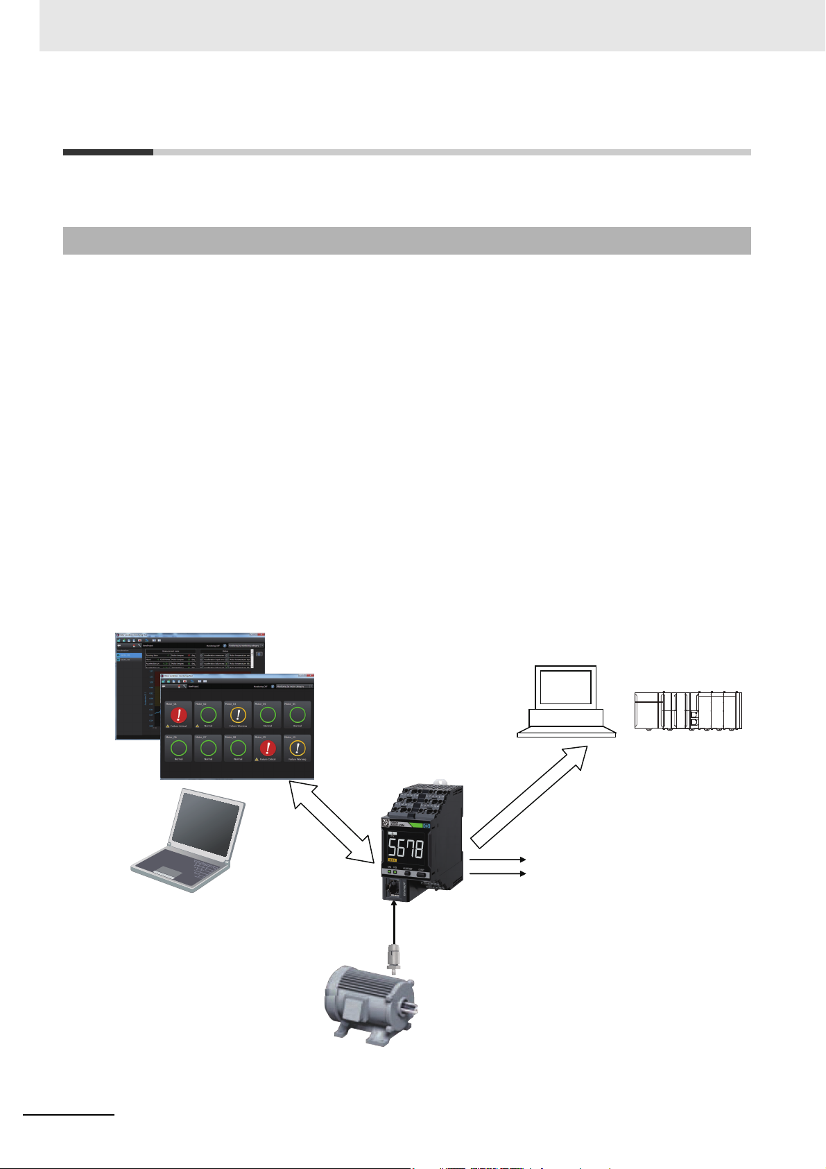
Sensors
Setting and
monitoring
Discrete outputs
software tool
(standard
accessory)
K6CM Motor Condition
Monitoring Device
PCs
(supporting EtherNet/IP)
Monitor
(with the EtherNet/IP)
Three-phase induction motor
PLC
1-1 Overview and Features
This section describes an overview and features of the K6CM.
1-1-1 What is the K6CM Motor Condition Monitoring Devices For?
K6CM Motor Condition Monitoring Device is a device that visualizes and monitors the state of the motor
by measuring the feature quantity of the three-phase induction motor. Depending on the feature quantity to be measured, you can select from the following three types.
• Vibration & temperature type: Measure vibration (acceleration, velocity) and motor temperature
• Insulation resistance type: Measuring insulation resistance
• Comprehensive current diagnosis type: Measures the degradation level and current
By properly using these three types as necessary, you can catch the state of the induction motor and
decide the appropriate maintenance time.
Features
• Software tool "Motor condition monitoring Tool" that is provided with the K6CM device enables immediate setup and status monitoring.
• With the built-in EtherNet/IP, this K6CM device can also be monitored by PLCs.
• Confirmation of the K6CM device front display makes monitoring on site easy.
• Alarm output threshold (Caution, Critical) can be set for each measured value.
• Trigger function enables measurement at required timing.
• Errors of the K6CM device itself and when to be replaced can also be detected.
1 - 2
K6CM Motor Condition Monitoring Device User’s Manual (N219)
Page 23

1-1-2 Features
z K6CM Common Functions
• Two levels of warning failure and critical failure are prepared as alarm monitoring levels. Two outputs of the transistor are possible when the alarm occurs.
• Trigger functions using an external input (*1) or internal set value comparison enable measuring
and monitoring only when specified conditions such as startup of the motor are met.
• The software tool enables initial settings of the K6CMs and alarm monitoring of measurement values. It also enables reading of measurement values at specified intervals and automatic data storage (with the CSV format).
• The K6CM device supports the EtherNet/IP network and can be monitored remotely with it.
• Multiple K6CM devices can be connected to one PLC or one PC, and multiple motor statuses can
be monitored at one time.
• Measurement value and internal data can be read, and alarm setting values and other setting values can be written (*2) with the PLC and PC via EtherNet/IP (i.e., tag data link, CIP message
communications).
*1. For the insulation resistance type K6CM device, the trigger function using the external input can be supported
for the EIP CPU version 1.10 or higher.
*2. Tag data link can be read only. Write not possible.
1 Overview
1-1 Overview and Features
1
1-1-2 Features
z Vibration and Temperature Type
• Simultaneous measuring and monitoring of motor vibration (i.e., acceleration and velocity) and
motor temperature are possible.
• Mainly bearing wears can be detected by the acceleration.
• Mainly load imbalance and misalignment can be detected by the velocity.
z Insulation Resistance Type
• Insulation resistance can be measured and monitored.
• Resistance leakage current (Ior) can be measured (Alarm output cannot be performed.)
• Capacitive leakage current (Ioc) can also be measured (Can be read via EtherNet/IP. Unit display
and alarm output cannot be performed.)
K6CM Motor Condition Monitoring Device User’s Manual (N219)
1 - 3
Page 24
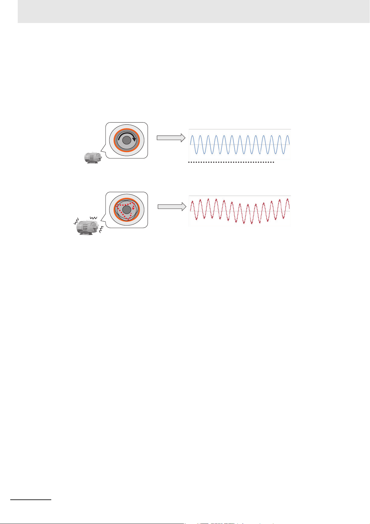
1 Overview
(1) Motor and load are normal.
Cross-sectional view of the motor
Cross-sectional view of the motor
(2) An abnormality is occurring.
The current is a smooth "sine wave".
"Noise" may come up in the current.
Smooth rotation
Abnormal vibration
z Comprehensive current diagnosis Type
• Motor malfunction (called "degradation level") can be detected by measuring and monitoring the
• The degradation level is the conversion of the degree of deviation of the current waveform
• The K6CM can also detect motor peripheral malfunctions affecting the rotating shaft of the motor.
current including harmonic components.
between the normal motor and the abnormal motor in numerical values.
1 - 4
K6CM Motor Condition Monitoring Device User’s Manual (N219)
Page 25

1 Overview
1-2 List of Models
This section shows the models of the K6CM device and the dedicated sensor.
Specifications
z Vibration & Temperature Type
K6CM device K6CM-VBMA-EIP 100 to 240 VAC
K6CM-VBMD-EIP 24 V AC/DC
Sensor (sensor head and pre-amplifier)*1
*1. The sensor head and the pre-amplifier are calibrated and inspected as a set at the factory shipment. Be sure
to use them with the combination shipped.
z Insulation Resistance Type
K6CM device K6CM-ISMA-EIP 100 to 240 VAC
Sensor (ZCT (IRT)) *1
*1. ZCT (IRT) stands for Zero Current Transformer (Insulation Resistance Transformer).
K6CM-VBS1 Mounting: M6 screw
K6CM-ISMD-EIP 24 V AC/DC
K6CM-ISZBI52 Rated voltage: 200 to 480 VAC, through hole diameter
1-2 List of Models
1
Model Specifications such as power supply voltage
Model Specifications such as power supply voltage
52 mm
z Comprehensive Current Diagnosis Type
Model Specifications such as power supply voltage
K6CM device K6CM-CIMA-EIP 100 to 240 VAC
K6CM-CIMD-EIP 24 V AC/DC
Sensor (CT) K6CM-CICB005 Rated primary current: 5 A
K6CM-CICB025 Rated primary current: 25 A
K6CM-CICB100 Rated primary current: 100 A
K6CM-CICB200 Rated primary current: 200 A
K6CM-CICB400 Rated primary current: 400 A
K6CM-CICB600 Rated primary current: 600 A
K6CM Motor Condition Monitoring Device User’s Manual (N219)
1 - 5
Page 26
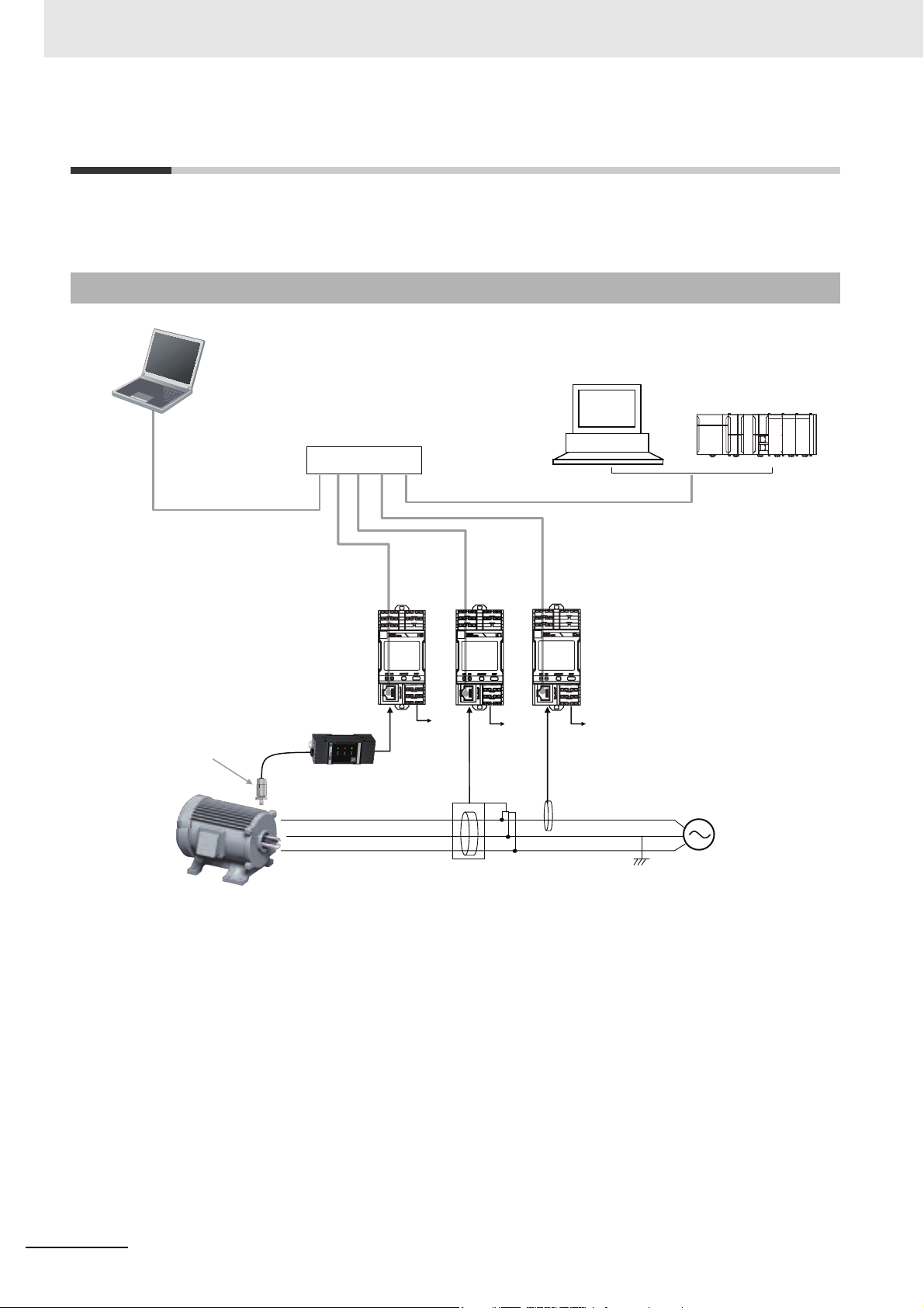
1 Overview
ZCT(IRT)
CT
Transistor Output
Alarm × 2 points,
self-diagnosis × 1 point
Three-phase AC power
Industrial switching hub
(e.g., W4S1)
(*1)
Dedicated cable
S-phase
ground
*1. When making initial settings,
connect this tool to each
motor status monitoring
device one to one using an
Ethernet cable.
Comprehensive
current diagnosis
type
• Required settings
Insulation
resistance
type
Vibration &
temperature
type
K6CM
Motor Condition Monitoring Device
• Monitoring
• Monitoring
• Initial setting (*1)
Software tool
EtherNet/IP
EtherNet/IP
PLC
PC
Vibration & temperature
sensor head
Vibration &
temperature sensor
pre-amplifier
Three-phase induction motor
1-3 System Configurations
This section describes the overall system configurations of the K6CM and the I/O configuration for each
monitor type of K6CM devices.
1-3-1 Overall System Configuration
1 - 6
K6CM Motor Condition Monitoring Device User’s Manual (N219)
Page 27
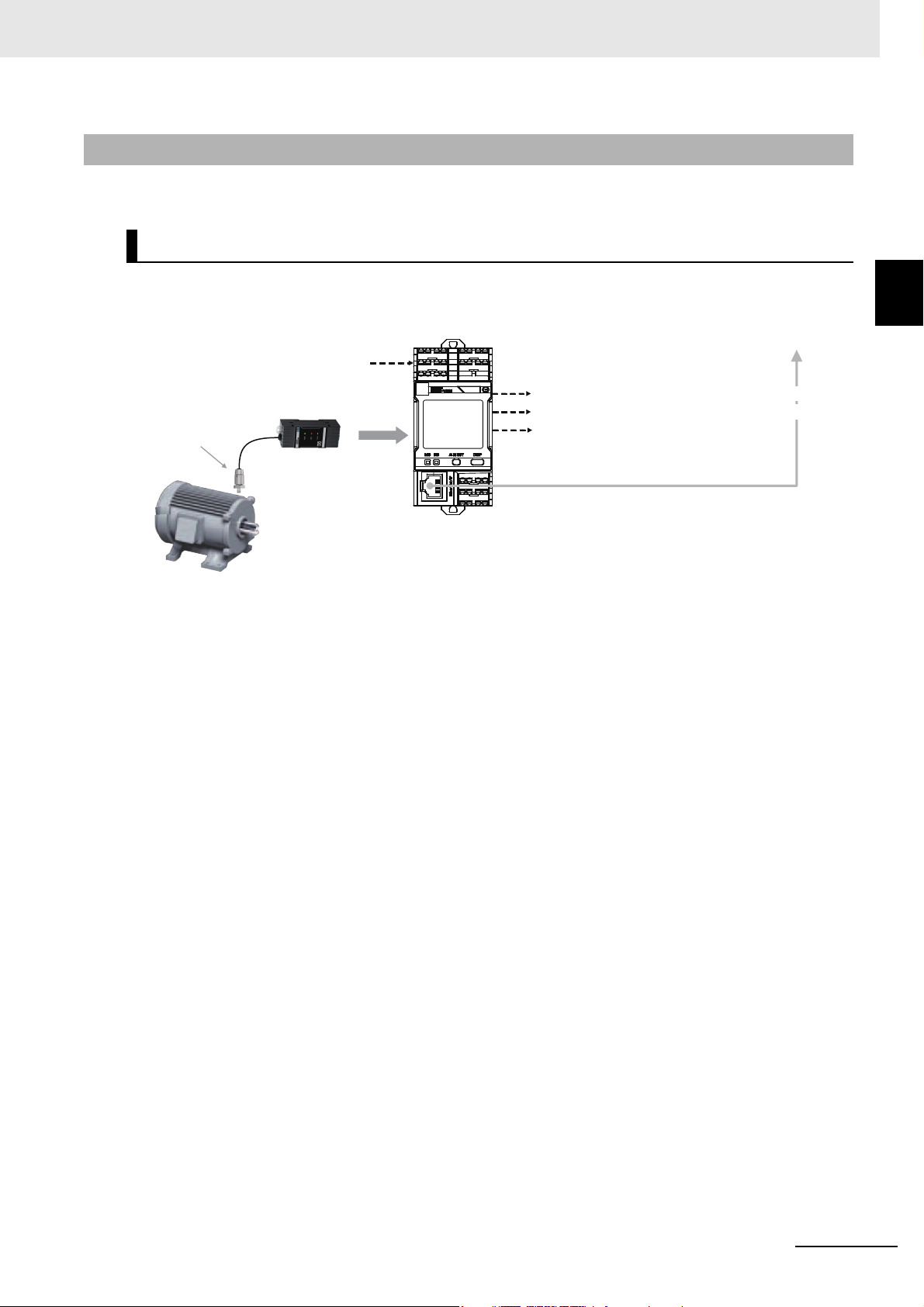
1-3-2 I/O Configuration by Monitor Type
Vibration & temperature
sensor pre-amplifier
Three-phase induction motor
Vibration &
temperature
sensor head
K6CM-VBM
Vibration &
temperature type device
(When necessary)
External trigger input
Transistor Output
Self-diagnosis output
EtherNet/IP (Ethernet cable)
*2
*1
To the software tool,
PC software and/or PLC
Comprehensive alarm (failure warning) output
Comprehensive alarm (failure critical) output
The input and output system configurations for each monitor types of K6CM devices are as follows.
K6CM-VB Vibration & Temperature Type
1 Overview
1-3 System Configurations
1
1-3-2 I/O Configuration by Monitor Type
*1. The dedicated cable between the sensor head and the pre-amplifier is 2.9 m long. It cannot be extended.The
sensor head and the pre-amplifier are calibrated and inspected as a set at the factory shipment. Be sure to
use them with the combination shipped. For details, refer to Installation of the Vibration Sensor Head on page
5-7.
*2. The dedicated attached cable between the pre-amplifier and the K6CM device is 1 m. It can be extended up
to a maximum length of 100 m. Refer to A-5 Individual Specifications of the Dedicated Sensor on page A-10
for recommended cables.
Note When you use an inverter to drive the motor, you may not be able to check the degradation tendency of
the motor. However, under the following conditions, changes in acceleration are more likely to be confirmed.
• When the inverter driving frequency is 50 Hz or more and the frequency is stable
• When the carrier frequency of the inverter is 12.5 kHz or more and the frequency is stable
Use an inverter after trying according to your installation environment.
K6CM Motor Condition Monitoring Device User’s Manual (N219)
1 - 7
Page 28
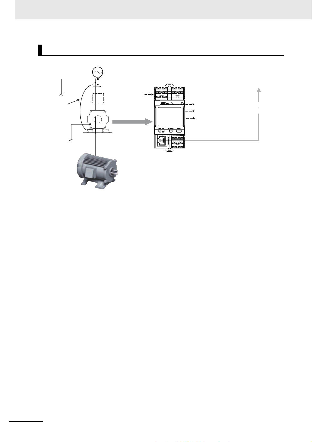
1 Overview
K6CM-IS Insulation Resistance Type
Voltage input
(Attached cable
is 1 m) It can
be extended
up to 100 m.
Earth
S-phase ground
FG
*3
Inverters
(When necessary)
External trigger input
Insulation resistance
sensor (ZCT (IRT))
*1
Wiring length between
ZCT (IRT) and
the motor is 40 m
K6CM-ISM
Insulation
Resistance
Type Device
To the software tool,
PC software and/or PLC
Transistor Output
Comprehensive alarm (failure warning) output
Comprehensive alarm (failure critical) output
Self-diagnosis output
EtherNet/IP (Ethernet cable)
Three-phase induction motor *2
*1. The distance between the insulation resistance sensor (ZCT (IRT)) and K6CM device is 1 m with the dedi-
cated attached cable.
*2. Motor capacity of 7.5 kW or less (Measurement error will increase if exceeding this value.)
*3. According to IEC 60364 TT method
1 - 8
K6CM Motor Condition Monitoring Device User’s Manual (N219)
Page 29
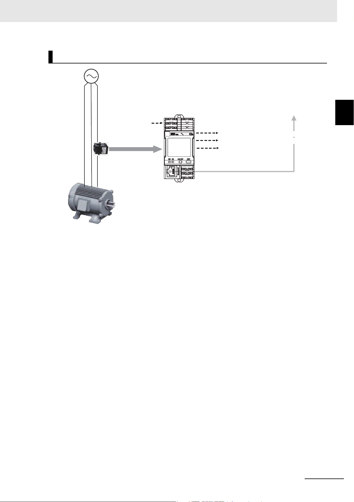
K6CM-CI Comprehensive Current Diagnosis Type
1 Overview
1-3 System Configurations
K6CM-CIM
Comprehensive current
diagnosis Type Device
(When necessary)
External trigger input
Dedicated CT *1
Three-phase induction motor
*1. The dedicated cable between the dedicated CT and the K6CM device is 2.9 m long. It cannot be extended.
Also, there is no designation in the phase to be installed. Be careful of the installation direction stated on the
CT label and mount it to any one phase.
Note The level of degradation may vary when the motor is driven by the inverter. In that case, slightly shift the
inverter drive frequency.
Also always measure and monitor the level of degradation at the same inverter drive frequency.
Mount a dedicated CT between the motor and the inverter.
Transistor Output
Comprehensive alarm (failure warning) output
Comprehensive alarm (failure critical) output
Self-diagnosis output
EtherNet/IP (Ethernet cable)
To the software tool,
PC software and/or PLC
1
1-3-2 I/O Configuration by Monitor Type
K6CM Motor Condition Monitoring Device User’s Manual (N219)
1 - 9
Page 30

1 Overview
1-4 Procedure
The K6CMs can be used in the following procedure.
Step Procedures Reference
1. Initial setting
on desk
2. Installation
and Wiring
3. Setting with
actual system configuration (via
hub)
Prepare a PC with Windows 7 or higher and Ethernet
cables.
Install the software tool.
↓
Start the software tool.
↓
Connect the software tool directly to the
K6CM device via Ethernet cable.
Turn ON the power to the K6CM device
↓
Select [Create Project],
• Set the IP address of each K6CM device
• Set default parameters
• Set other parameters (when necessary)
• Download IP address and (when necessary) parameters
to K6CM device.
• (When necessary) Set the motor name (K6CM group
name) of each K6CM.
▼
Install.
↓
Wire.
▼
Connect the software tool to the K6CM device (s) via hub.
↓
(When necessary) Change the parameters and download to
each K6CM device.
↓
Turn ON the power of the K6CM again and activate the
parameters.
▼
Either order is
acceptable
Section 4 Introduction
of the Software Tool
Section 2 Nomenclature and Functions
Section 5 Installation
and Wiring
Section 6 How to Use
the Software Tool
1 - 10
K6CM Motor Condition Monitoring Device User’s Manual (N219)
Page 31

Start measuring using the K6CMs.
↓
Record measurement values from the host system (i.e., the
software tool, PC, or PLC) to estimate an alarm set value to
be used as the monitoring standard.
• With the software tool, set the "Monitoring cycle" by press-
ing the [Option] Button, before monitor via EtherNet/IP
and log the measurement values.
4. Monitoring
and operation
5. Troubleshoot Troubleshoot
• With PC or PLC, Monitor via EtherNet/IP and log the measurement values.
↓
Estimate an alarm set values to be used as monitoring standard, considering the relationship between the change in
each measurement value and the fatal state of the motor.
↓
Determine the alarm set values as the monitoring standard
based on the monitoring and operation results.
↓
Change the setting of the alarm set values and make main
monitoring and operation.
▼
1 Overview
Section 3 Measuring
and Monitoring Mechanism
Section 7 Motor Monitoring with the K6CM
Devices and the Software Tool
Section 8 Monitoring
and Setting Using the
EtherNet/IP Devices
Section 9 Trouble
shooting
1-4 Procedure
1
K6CM Motor Condition Monitoring Device User’s Manual (N219)
1 - 11
Page 32

1 Overview
1 - 12
K6CM Motor Condition Monitoring Device User’s Manual (N219)
Page 33

Nomenclature and Functions
This section describes the nomenclature and functions of the K6CM devices, the vibration & temperature sensor, the insulation resistance sensor, and the dedicated current
transformer.
2-1 K6CM Device . . . . . . . . . . . . . . . . . . . . . . . . . . . . . . . . . . . . . . . . . . . . . . . . . 2-2
2-2 Vibration & Temperature Sensor . . . . . . . . . . . . . . . . . . . . . . . . . . . . . . . . . 2-9
2-3 Insulation Resistance Sensor (ZCT (IRT)) . . . . . . . . . . . . . . . . . . . . . . . . . 2-11
2-4 Dedicated CT . . . . . . . . . . . . . . . . . . . . . . . . . . . . . . . . . . . . . . . . . . . . . . . . 2-12
2
K6CM Motor Condition Monitoring Device User’s Manual (N219)
2 - 1
Page 34

2 Nomenclature and Functions
Sensor
Example) Dedicated CT
Three-phase induction motor
Push-In Plus terminal
IP address label
(Used to write down the IP address)
Measured value
LCD display
(When necessary)
External trigger input
EtherNet/IP port
Alarm bar display
EtherNet / IP (Ethernet cable)
Front key
To the software tool, PC
software and/or PLC
Transistor Output
Comprehensive alarm (failure warning) output
Comprehensive alarm (failure critical) output
Self-diagnosis error output
2-1 K6CM Device
The appearances of the K6CM device and the nomenclature and functions are as follows.
Overview
2 - 2
K6CM Motor Condition Monitoring Device User’s Manual (N219)
Page 35

2 Nomenclature and Functions
Nomenclature and Functions of the Front Panel of the K6CM Device
DIN Track hook
Push-In Plus terminals (*1)
Push-In Plus terminals (*1)
Alarm bar display
2-1 K6CM Device
LCD display for numerical value
such as measured value
Status
display
Product status
indication
Network status
indication
EtherNet/IP port
Unit of measurement value
(monitoring category) (*2)
Types of measurement such
as current value, minimum value,
and maximum value
[ARM RST] Key
Front operating part
[DISP] Key
Push-In Plus terminals (*1)
*1. Refer to "Push-In Plus terminals
layout" described below.
*2. Unit of measurement value
(monitoring category)
· Vibration and temperature type
G
mm/s
TT
· Insulation resistance type
MΩ
mA
· Comprehensive current diagnosis type
Cim
A
2
Name Meaning
Alarm bar display The LED bar emits light according to the state
of the comprehensive alarm (above the measurement value).
Unit of measurement
value (monitoring category)
The unit of the measurement value (monitoring category) is indicated by the following
LCD characters.
Press the [DISP] key to switch the display.
During measuring and monitoring, the following colors are
used.
• Comprehensive alarm (normal): green
• Comprehensive alarm (Warning): Yellow
• Comprehensive alarm (Critical): Red
Note : The above LCD color is retained after measuring and
monitoring.
Turns OFF when one of the following occurs:
when the power is OFF, when measuring and monitoring is
not started yet, when self-diagnos error occurs.
• "G": Acceleration, "mm/s": Velocity, "T": Motor temperature
"∆T": Temperature gap (Difference from room temperature
to room temperature) (Vibration & temperature type)
•"MΩ": Insulation resistance, "mA": Leakage current (Insula-
tion resistance type)
• "A": Current, "Cim": Degradation level (Comprehensive current diagnostic type)
K6CM Motor Condition Monitoring Device User’s Manual (N219)
2 - 3
Page 36

2 Nomenclature and Functions
Name Meaning
Types of measurement
such as present value,
minimum value, and maximum value
Numeric LCD display • When measuring and monitoring is started,
Status display K6CM device status is one of measuring and
Product and network status indications
External trigger input Trigger input by external input that sets the
When the K6CM device is being measured
and monitored, LCD character shown in the
right column indicates whether the measurement value displayed on the LCD is the present value, the minimum value, or the
maximum value.
Note : Switching display of current value,
minimum value, and maximum value
can be set by changing "Display
value selection" from the software
tool.(It is not switchable by front operation.)
the measurement value is displayed.
Switching display of the monitoring category on the right can be performed by
[DISP] key.
• With trigger (external trigger or internal trigger), "- - - -" is displayed if measuring and
monitoring is not started yet. When the
measuring and monitoring is completed,
the measurement value just before the end
is retained and displayed.
Note : When the vibration & temperature
sensor or the insulation resistance
sensor (ZCT (IRT)) is not connected,
"- - - -" is displayed and the MS
flashes. When the input range is
over, 7 segments will flash with the
maximum value of the input range.
For details, refer to Transition of Numeric LCD
Display on page 2-7.
monitoring in progress, self-diagnosis error,
operation summation status, with the LCD
character on the right.
Note : Running Time is a function to inform
you when to replace the K6CM
device. It is calculated from the internal temperature and the operation
time of the device.
Indicates the product status or network status
by LEDs.
K6CM device status during measuring and
monitoring (status display "MON").
• "PV": present value
• "MIN": minimum value
• "MAX": maximum value
The minimum and maximum values indicate the current minimum and maximum values in one measuring and monitoring
period.
The display is updated each time the minimum and maximum
values are updated. Both are retained at the end of measuring
and monitoring, but will be reset the next time the power is
turned ON again.
• Acceleration, Velocity, Motor temperature, Difference
between Motor temperature and room temperature (Vibration & temperature type)
• Insulation resistance, Leakage current (Insulation resistance type)
• Degradation level, current (Comprehensive current diagnosis type)
*1
• "MON": Measuring and monitoring in progress
• "ERR": Self-diagnosis error occurrence
• "AGE": operation totalization notification (recommendation
for exchange of product body)
• "MS": ModuleStatus. Displays the status of the K6CM
device. It is green when it is normal.
• "NS": Network Status. Displays the state of the communications. It lights or flashes green when it is normal.
Note : For details, refer to Product and Network Status Indi-
cations Details on page 2-6.
Measurement and monitoring can be started during the rise
from OFF → ON or the fall from ON → OFF, and measurement and monitoring up to the measurement time, or measurement and monitoring in the ON state can be selected.
2 - 4
K6CM Motor Condition Monitoring Device User’s Manual (N219)
Page 37

2 Nomenclature and Functions
Name Meaning
Front
operating part
Transistor Output
EtherNet/IP port Port for connecting Ethernet cable for com-
*1. "MON" always lights up when there is no trigger. When there is a trigger, it lights up during measuring and monitoring. It
turns off after measuring and monitoring is not started yet, and after measuring and monitoring is completed (only when
using the trigger function).
*2. The output state (ON/OFF) of the transistor is held at the end of measuring and monitoring (only when using the trigger
function).
*3. The setting function of transistor output type can be used with EIP CPU version 1.10 or later. It is fixed to Normally
closed with EIP CPU version less than 1.10.
[ARM RST]
Key
[DISP] Key Switch the unit of measurement value (moni-
Press the
[ALM RST]
and [DISP]
Keys simultaneously
Transistor
Output 1
Transistor
Output 2
Transistor
Output 3
Release the alarm latch (cancellation by
communication is impossible).
Note : Setting the alarm latch to "L" will latch
the alarm condition of comprehensive
alarm (Warning or Critical) (alarm bar,
transistor outputs 1 and 2). Release
this latched state.
toring category)
When pressed at the same time for 5 seconds
or more, initialize all settings of the K6CM
device and restore the Factory default.
Warning output of comprehensive alarm.(*2)
Transistor output type can be set to Normally
Closed or Normally Open. (* 3)
Critical output of comprehensive alarm.(*2)
Transistor output type can be set to Normally
Closed or Normally Open. (* 3)
Self-diagnosis error output.
Transistor output type can be set to Normally
Closed only.
* Self-diagnosis error is a function to detect
errors of the K6CM device itself.
munications with the software tool, PLC, and
PC.
If you press the [ALM RST] key during measuring and monitoring, it returns to the comprehensive alarm state at that point
(both the alarm bar and transistor outputs 1 and 2).
Every time it is pressed, the unit of measurement value
changes as follows.
• Vibration & temperature type: "G" → "mm/s" → "T" → "∆T"
(→ "G")
• Insulation resistance type: "MΩ" → "mA" (→ "MΩ")
• Comprehensive current diagnosis type: "Cim" → "A" (→
"Cim")
----
• Normally closed output type
ON: Comprehensive alarm is normal
OFF: Comprehensive alarm is warning or critical
• Normally open output type
ON: Comprehensive alarm is warning or critical
OFF: Comprehensive alarm is normal
It turns OFF regardless of the output type in either of the following cases.
• Measurement and monitoring is not started (only when
using the trigger function).
• Self-diagnosis error
In the following cases, ON
• When Self-diagnosis error does not occur
In the following cases, OFF
• Self-diagnosis error occurrence
It is with straight / cross cable automatic discrimination function.
2-1 K6CM Device
2
K6CM Motor Condition Monitoring Device User’s Manual (N219)
2 - 5
Page 38

2 Nomenclature and Functions
z Product and Network Status Indications Details
Name Color Status Operating condition
MS Module Status Green Lit. Normal status
Red Lit. Damaged fault (Measurement CPU data flash error, Main CPU data flash
-- Not lit. No power supply
NS Network Status Green Lit. Tag data link or message connection established
Red Lit. IP address duplication status
-- Not lit. No power supply
Note For the countermeasures for the above operation error, refer to Section 9 Trouble shooting.
error)
Flashing One of the following conditions
Vibration & temperature sensor not connected, Insulation resistance sensor (ZCT (IRT)) not connected, Measurement CPU error, Main CPU error,
Present value input error, Maximum value input error, or Minimum value
input error
Flashing No tag data link or message connection established
Flashing The connection has timed out, or the BOOTP server connection error
state
2 - 6
K6CM Motor Condition Monitoring Device User’s Manual (N219)
Page 39

2 Nomenclature and Functions
Power OFF
No lit.
10 seconds or less
7 segment blinking
Measured value displayed
"MON" goes on
"MON" goes on
"MON" goes off
"MON" goes off
"ERR" goes on when the sensor
is not connected.
Measurement and monitoring conditions were met.
"- - - -" displayed
All lit
After measuring and monitoring
(only when using the trigger)
When the power
supply is turned ON
or the software reset
*1
is done.
Input range over occurs.
Measurement and monitoring is not started yet
Measurement and monitoring is
not done (only when using the
trigger function)
When measurement and
monitoring condition is met
Power supply to the device
Not used.
Not used.
Transistor Output 1 (+)
Transistor Output 1 (-)
Transistor Output 2 (+)
Transistor Output 2 (-)
Transistor Output 3 (+)
Transistor Output 3 (-)
CTK
IRT2:
Supply to
sensor 10 V (+)
IRT0:
Sensor input (+)
VBS 1:
Sensor input (-)
VBS 3:
Supply to
sensor 10 V (-)
IRT1:
Sensor input (-)
IRT3:
Supply to
sensor 10 V (-)
CTL
External trigger
input (+)
External trigger
input (-)
K6CM-VB
Vibration & temperature type
VBS 0:
Sensor input (+)
VBS 2:
Supply to
sensor 10 V (+)
K6CM-IS
Insulation resistance type
K6CM-CI
Vibration & temperature type
1
2
3
5
6
7
8
10
11
12
13
14
18
17
16
15
9
4
7
8
10
11
12
9
7
8
10
11
12
9
7
8
10
11
12
9
z Transition of Numeric LCD Display
The numerical LCD display will transition as follows after turning ON the power supply or after soft-
*1
ware reset
.
2-1 K6CM Device
2
K6CM Motor Condition Monitoring Device User’s Manual (N219)
*1. It depends on the Device reset button operation from the software tool or software reset command from Eth-
erNet/IP.
z Push-In Plus Terminals Layout
2 - 7
Page 40

2 Nomenclature and Functions
Status of Alarm Bar, Status Indication, and Transistor Output for
Each Status
Status Description Alarm bar
Measuring and monitoring
Not yet
Comprehensive
alarm: normal
During measuring and
monitoring
After measuring
and monitoring
(only when using the trigger function)
When the self-diagnosis
error occurs
When the power is OFF
Comprehensive
alarm:
Warning
Comprehensive
alarm: Critical
Measurement and monitoring are not
completed until the measured value
is set after the power is turned ON.
All measurement values are in normal condition.
There is no "Critical" in the measurement value, and even one of them
has "Warning".
There is "Critical" in at least one
measurement value.
When using the trigger function
(external trigger or internal trigger),
the measuring and monitoring is
completed.
Self-diagnosis error is occurring
regardless of measuring and monitoring status.
----
Status dis-
play
Not lit. Not lit. OFF OFF OFF
Green “MON”
Yellow
Red
The sta-
tus at the
end is
kept.
Not lit. “ERR” OFF OFF OFF
Not lit. Not lit. OFF OFF OFF
Not lit. The status
Transistor
output 1
*1
ON
*1
OFF
*1
OFF
at the end is
kept.
Transistor
output 2
*1
ON
*1
ON
*1
OFF
The status
at the end is
kept.
Transistor
output 3
ON
ON
ON
ON
*1. This is the case when the transistor output type is set to Normally Closed. In the case of Normally Open, ON/OFF is op-
posite to the above.
2 - 8
K6CM Motor Condition Monitoring Device User’s Manual (N219)
Page 41

2 Nomenclature and Functions
To the K6CM-VBM
Vibration and
temperature type
device
K6CM-VBS
Sensor head
Connector
connection
Cable length:
0.3 m
Cable length:
2.6 m
Cable length:
1 m
K6CM-VBS
Pre-amplifier
2-2 Vibration & Temperature Sensor
The appearance of the vibration and temperature sensor and the name and functions of each part are
as follows.
Overview
2-2 Vibration & Temperature Sensor
2
K6CM Motor Condition Monitoring Device User’s Manual (N219)
2 - 9
Page 42

2 Nomenclature and Functions
PWR LED
ERR LED
COM LED
To the sensor head
To the K6CM-VBM
Vibration and
temperature type
device
LED Name Color Status Operating condition
PWR Pre-amplifier power
supply
Green Lit. Normal status
---- Not lit. Power not supplied
ERR Pre-amplifier fault Red Lit. Self-diagnosis error
occurred
COM Communication
between pre-amplifier
and K6CM
Yellow Lit. STX transmission, lit
at reception 50 ms
Terminal number of
the K6CM device
Vibration & temperature sensor
side
Line color
7 VBS 0: Sensor input (+) Red and white
8 VBS 1: Sensor input (-) Red
9 VBS 2: Supply to sensor 10 V (+) Black
10 VBS 3: Supply to sensor 10 V (-) Black and white
Nomenclature and functions of the pre-amplifier
Nomenclature and functions of the sensor head
To the pre-amplifier
Cable part
Detection direction (Z axis direction)
M6 screw
At the top of the armor of the induction motor, cut the tap into which
the M6 screw vertically enters, screw it in and install it.
The position of the tap is recommended above the bearing of the
induction motor.
When installing, removing the connector of the cable facilitates
handling.
For the M6 type, a magnet for positioning is enclosed.
2 - 10
K6CM Motor Condition Monitoring Device User’s Manual (N219)
Page 43

2 Nomenclature and Functions
Voltage input
L1: R (black)
L2: S (red)
L3: T (white)
Cable length:
1 m
Through-hole
diameter: 52 mm
Insulation resistance sensor
Split-type
Cable length: 1 m
To the K6CM-ISM
Insulation
Resistance Type
Device
Terminal number of
the K6CM device
Insulation resistance sensor
(ZCT (IRT)) side
Line color
7 IRT0: Sensor input (+) Red and white
8 IRT1: Sensor input (-) Red
9 IRT2: Supply to sensor 10 V (+) Black
10 IRT3: Supply to sensor 10 V (-) Black and white
2-3 Insulation Resistance Sensor (ZCT
(IRT))
2-3 Insulation Resistance Sensor (ZCT
The appearance of the insulation resistance sensor ZCT (IRT)
(*1)
and the name and functions of each
part are as follows.
*1. ZCT (IRT) stands for Zero Current Transformer (Insulation Resistance Transformer).
Nomenclature and functions of the Insulation resistance sensor
(ZCT (IRT))
(IRT))
2
K6CM Motor Condition Monitoring Device User’s Manual (N219)
2 - 11
Page 44

2 Nomenclature and Functions
K6CM-CIM
Comprehensive current
diagnosis type device
The dedicated CT has the mounting direction. Mount a
dedicated CT to any one phase according to the mounting
direction stated on the CT label when you mount it.
Ferrules
Load side (L)
Split/fastening
hook
Cable for Dedicated CT (included)
Cable length 2.9 m
Terminal cover on
the secondary side
of the CT
For fixing of
binding band
etc.
Power supply
side (K)
Dedicated CT
Split-type
Terminal number of
the K6CM device
Dedicated
CT side
7CTK
8CTL
2-4 Dedicated CT
The appearance of the dedicated CT and the name and functions of each part are as follows.
Nomenclature and functions of the dedicated CT
2 - 12
K6CM Motor Condition Monitoring Device User’s Manual (N219)
Page 45

Measuring and Monitoring Mechanism
This section describes the measuring and monitoring mechanism of the K6CM devices.
3-1 Overview . . . . . . . . . . . . . . . . . . . . . . . . . . . . . . . . . . . . . . . . . . . . . . . . . . . . . 3-2
3-2 Measurement System . . . . . . . . . . . . . . . . . . . . . . . . . . . . . . . . . . . . . . . . . . 3-3
3-2-1 Sampling of measured values . . . . . . . . . . . . . . . . . . . . . . . . . . . . . . . . . . . . . 3-3
3-2-2 Moving average . . . . . . . . . . . . . . . . . . . . . . . . . . . . . . . . . . . . . . . . . . . . . . . . 3-4
3-2-3 Trigger Mode . . . . . . . . . . . . . . . . . . . . . . . . . . . . . . . . . . . . . . . . . . . . . . . . . . . 3-5
3-2-4 Maximum Value and Minimum Value of Measured Value . . . . . . . . . . . . . . . . 3-10
3-3 Monitoring Mechanism . . . . . . . . . . . . . . . . . . . . . . . . . . . . . . . . . . . . . . . . 3-12
3-3-1 Types of Individual Alarms . . . . . . . . . . . . . . . . . . . . . . . . . . . . . . . . . . . . . . . 3-12
3-3-2 Comprehensive Alarm Judgment . . . . . . . . . . . . . . . . . . . . . . . . . . . . . . . . . . 3-12
3-3-3 Relationship Between Alarm and Display/Output . . . . . . . . . . . . . . . . . . . . . . 3-13
3-3-4 Guide for Setting Alarm . . . . . . . . . . . . . . . . . . . . . . . . . . . . . . . . . . . . . . . . . 3-18
3
K6CM Motor Condition Monitoring Device User’s Manual (N219)
3 - 1
Page 46

3 Measuring and Monitoring Mechanism
Measured
value B
Update
measurement
display
Capture
measured value
Sensor
Warning result
Transistor Output
Red
OFF
OFF
Yellow
OFF
ON
Green
Normal
ON
ON
Self-diagnosis
error output
OFF
OFF
ON
External trigger input
Internal setting value
Software tool
EtherNet/IP
Sensor
PLC etc.
and/or
Alarm bar
Output 1 Output 2 Output 3
LCD (Not lit.)
Latch selection
available
N.O. is
selectable *1
OFF
Critical failure
occurrence
Warning failure
occurrence
Critical result
Warning result
Critical result
K6CM
Measured
value A
Always,
external trigger,
or internal trigger
Individual alarm
for each measured value
Comprehensive
alarm output
as a device
OR logic of each
measured value
Critical
Warning
Critical
Warning
3-1 Overview
The measurement makes it possible to calculate the measurement value based on the input from the
sensor. The calculation is executed inside the K6CM even in the unmeasured state before the trigger
start, and the measurement display is updated when the trigger is established. The monitoring (alarm)
captures the measured value when the trigger is established. The monitoring (alarm) involves first judging the threshold value of the Warning/Critical for each measured value, and then judging whether each
measured value is within the Warning/Critical level as an "individual alarm". Next, the OR logic is
obtained for each "individual alarm" and Normal/Warning/Critical is judged for each monitor target as
the "Comprehensive alarm". The "Comprehensive alarm" is displayed on the front LCD alarm bar of the
K6CM device and transistor output is performed (*1). Both measurement and monitoring (alarm) are
executed either always or when a trigger condition is satisfied.
*1. If the alarm latch is set to "Yes", the alarm status of the K6CM comprehensive judgment (such as alarm bar
and transistor outputs 1 and 2) is held. Pressing the [ALM RST] key on the front of the device releases the
latch. Also, the transistor output type of output 1 and output 2 can be set to Normally closed or Normally open.
As shown in the figure, it is as follows.
3 - 2
K6CM Motor Condition Monitoring Device User’s Manual (N219)
*1. It can be set to Normally open
for EIP CPU version 1.10 or
later of the K6CM device and
the software tool version 1.1.0
or higher.
Page 47

3 Measuring and Monitoring Mechanism
Measured value 1 is the current value
until sampling of measured value 2 is
completed.
Sampling period
Measured value 2
Measured value 1
Measured value 2 is the current value
when sampling of measured value 2 is
completed.
3-2 Measurement System
3-2-1 Sampling of measured values
The input from the sensor is given to the K6CM device as a measured value in every sampling period.
The sampling period depends on the measured target as follows.
Monitor type Measurement target Sampling period
Vibration and temperature type
Insulation resistance type
Comprehensive current diagnosis type
Also, until the next sampling is completed, the present measured value is held as the current value.
When the power is turned OFF, the held measurement value is reset.
Acceleration 50 ms
Velocity 0.5 s
Temperature 0.5 s
Insulation resistance 10 s (Normal mode)
60 s (Inverter special measurement
mode)
Degradation level 5 s
Current 5 s
3-2 Measurement System
3
3-2-1 Sampling of measured values
Note The sampling of the measured value is performed internally even in the case of the unmeasured state
before the trigger start.
K6CM Motor Condition Monitoring Device User’s Manual (N219)
3 - 3
Page 48

3 Measuring and Monitoring Mechanism
Measured value of
past 4 times
Current measured value Current measured value (after moving average)
Calculate the average value of measured values
3-2-2 Moving average
The moving average is the process of assuming the average value of past n times of measured values
which includes the measured value of that time to be a current measured value each time the sampling
of the measured value is performed. The moving average makes it possible to suppress the instantaneous fluctuation of the measured value and make the tendency of the measured value easier to see.
The image of moving average is shown below.
Measurement result before moving average
(a)
Note The sampling of the measured value is performed internally even in the case of the unmeasured state
before the trigger start.
(b)
After moving average of (a) (moving average times n = 4)
3 - 4
K6CM Motor Condition Monitoring Device User’s Manual (N219)
Page 49

3-2-3 Trigger Mode
ON
OFF
Measuring time
Measurement and monitoring
ON
OFF
Measuring time
Measurement and monitoring
ON
OFF
Measurement and monitoring
Measuring time
Measurement and monitoring
Set
value
Set
value
Measurement and monitoring
Trigger is a function of updating and monitoring the measured values when certain conditions are met.
To observe the aging of the motor, it is necessary to set the installation state, load, and rotation speed
of the motor during measurement to the same condition, and to measure the motor rotating at a constant speed avoiding the state where the motor is stopped or accelerating or decelerating. Depending
on the application, select the trigger mode from Always (while power is ON), External Trigger, or Internal Trigger. The operation of each trigger mode is shown in the table below.
3 Measuring and Monitoring Mechanism
3-2 Measurement System
Trigge r
mode
Always (while
power is ON)
Start condition
of measuring
and monitoring
All times after
turning ON the
power of the
K6CM device
Depends on external conditions
Rising edge Falling edge Level
Trigge r typ e
Always measuring
External trigger
Internal trigger
• Start condition
• End condition
Depends on the
relationship
between the measurement value
and the set value
(trigger level)
• Start condition
• End condition
When the external trigger
input changes from OFF to
ON
After the measurement
time has elapsed
When the measurement
value exceeds the set
value (trigger level)
After the measurement
time has elapsed
When the external trigger
input changes from ON to
OFF
After the measurement
time has elapsed
Measuring time
Set
value
Measurement and monitoring
When the measurement
value falls below the set
value (trigger level)
After the measurement
time has elapsed
While the external input is in
the ON state
While the measurement
value exceeds the set value
(trigger level)
Note : For the insulation
resistance, this is
while present value
falls below the set
value.
When selecting external trigger or internal trigger mode, set measurement start and end conditions by
selecting trigger type.
3
3-2-3 Trigger Mode
K6CM Motor Condition Monitoring Device User’s Manual (N219)
3 - 5
Page 50

3 Measuring and Monitoring Mechanism
Status display
Measuring and monitoring
Time
Power ON
(*1)
Measurement and monitoring period
Measured value
Numeric LCD display
“MON” “MON”
During measuring and monitoring
Power ON the next time
Either the current value, the minimum value,
or the maximum value of the measured value
Either the current value,
the minimum value,
or the maximum value
of the measured value
During measuring
and monitoring
Measuring
and monitoring
Detailed information on trigger mode and behavior by status
The operation of the K6CM device, trigger mode and state, and the operation results from the Motor
condition monitoring Tool and EtherNet/IP are as follows.
K6CM device Operation
Trigger
mode
Always While the power is ONMeasurement and
External
trigger
Or
Internal trigger
Status
Measuring and
monitoring Not yet
During measuring
and monitoring
After measuring
and monitoring
*1. The measuring and monitoring status can be confirmed by "K6CM status" from EtherNet/IP.
Measuring and
monitoring sta-
monitoring
No measuring and
monitoring
Measurement and
monitoring
No measuring and
monitoring
tus
*1
Front Numeric LCD Dis-
play
Either the present value,
the minimum value, or the
maximum value of the
measurement value
"- - - -" is displayed Not lit. The read value is 0
Either the present value,
the minimum value, or the
maximum value of the
measurement value
Holding and displaying
values at the end of measuring and monitoring
Status dis-
play
"MON" The present value, the minimum
"MON" The present value, the minimum
Not lit. The held values are read out at the
Motor condition monitoring Tool
and read value with the Ether-
value, and the maximum value of
the measurement value can be read
out individually
value, and the maximum value of
the measurement value can be read
out individually
end of the measuring and monitoring
Net/IP
z Example of Operation When the Trigger Mode Is "Always"
3 - 6
*1.In the above figure, the power-ON state and the unmeasured state (i.e., the state until
the measured value is calculated) that exist immediately after turning ON the power
as shown below are omitted.
K6CM Motor Condition Monitoring Device User’s Manual (N219)
Page 51

3 Measuring and Monitoring Mechanism
Alarm bar
Status display
ON
OFF
ON
OFF
ON
OFF
Numeric LCD display
Transistor Output 1
Transistor Output 2
Transistor Output 3
Self-diagnosis: Normal: ON
Error: OFF
No lit.
"----"
Measuring and monitoring, Not yet (*1)
At the start of power
No lit.
LCDAll lit.
LCDAll lit.
Approx. 2 seconds
Power ON
(*1)
Time
During measuring
and monitoring
One sampling period
Note: Sampling period depends on
measured value and setting
When the trigger type is always: "MON"
When the trigger type is internal or
external trigger: Not lit.
Time
Measured value
Power ON
Trigger
start
(*1)
Numeric LCD
display
Status display “MON”Not lit. Not lit.Not lit.
Measuring and
monitoring, Not yet
Measurement and monitoring period
Measuring
and monitoring
Power ON the next time
Measuring and
monitoring Not yet
During measuring
and monitoring
After measuring
and monitoring
Either the current value,
the minimum value, or
the maximum value of
the measured value
The status at the
end keeps.
“- - - -“ “- - - -“
The following is an example of the operation from the time the power is turned ON until the measured
value is calculated. In any case, always (no trigger) and external trigger and internal trigger, the same
operation occurs.
3-2 Measurement System
3
3-2-3 Trigger Mode
*1. Current value of the measurement status is unmeasured status.
z Example of Operation When the Trigger Mode Is "External Trigger Input" or
"Internal Trigger"
K6CM Motor Condition Monitoring Device User’s Manual (N219)
*1.In the above figure, the power-ON state and the unmeasured state (i.e., the state until
the measured value is calculated) that exist immediately after turning ON the power
as shown on page 3-7 are omitted.
3 - 7
Page 52

3 Measuring and Monitoring Mechanism
Can measure
and monitor
Sampling period × 2
Motor
Measured value
Trigger timing
Can measure and monitor
Measured
value 1
Trigger start
Sampling period
If the trigger condition is
satisfied during calculation
of "Measured value 3", the
measured value is updated with
"Measured value 2" which has
been calculated during startup of
the motor.
If the trigger condition is satisfied after calculating the "Measured value 3", the
measured value can be updated with the "Measured value 3" which is calculated
during stable operation of the motor.
If the trigger condition is satisfied after sampling period × 2, the measured value
is a value secured after calculation of "Measured value 3".
Measured
value 3
Sampling period × 2
During
startup
of the
motor
Changing
motor
rotation
speed
During stable motor
operation
During stable motor operation
Rotation
speed
Measured
value
Trigger startTrigger release
Measured
value 2
Cannot measure
and monitor
Cannot measure
and monitor
Before
operation
of the
motor
Trigger Settings
To observe the aging of the motor, it is necessary to set the condition of the motor at measurement to
the same condition, and to measure the motor in a stable state avoiding the state where the motor is
stopped or accelerating or decelerating. Use trigger to start measurement at appropriate timing. Refer
to the following.
1 Determination of trigger mode
Refer to 3-2-3 Trigger Mode on page 3-5 and decide the trigger mode and trigger type according
to the application.
2 Determination of moving average times
Reducing the moving average times can help capture instantaneous fluctuations.
Increasing the moving average times can suppress the steep fluctuation of measured values
and capture the overall trend.
Determine the moving average times of measured values according to the state of measured
value.
3 Determination of trigger start timing (when trigger mode is external trigger or internal trigger)
To obtain the measured value when the state of the motor is stable, start the trigger after the
sampling period * 1 × (moving average times + 1) has elapsed after the motor state became stable.
(*1 The sampling period differs for each measured target. Refer to 3-2-1 for details).
Also, release the trigger during stable operation of the motor.
The following is an example of trigger without the moving average and also with the moving average.
z Trigger example without moving average (moving average times = 1)
3 - 8
K6CM Motor Condition Monitoring Device User’s Manual (N219)
Page 53

3 Measuring and Monitoring Mechanism
Can
measure
and
monitor
Motor
Measured
value after
moving average
Trigger timing
Measurement and monitoring are possible.
Measured
value 3
Trigger start
Sampling period
If the trigger condition is
satisfied during calculation of
"Measured value 4", the
measured value is updated with
"Measured value 2 and 3" which
have been calculated during startup
of the motor.
If the trigger condition is satisfied after calculating "Measured value 4", the
measured value can be updated with "Measured value 3 and 4" which is
calculated during stable operation of the motor.
If the trigger condition is satisfied after sampling period × 3, the measured
value is a value secured after calculation of "Measured value 4".
Measured
value 4
Sampling period × 3
During
startup
of the
motor
Changing
motor
rotation
speed
Before
operation
of the
motor
During stable
motor operation
During stable motor operation
Rotation
speed
Measured
value
Trigger start Trigger release
Measuring time
Cannot measure
and monitor
Sampling period × 3
Measured
value 1
Measurement and monitoring are not possible.
Measured
value 2
z Trigger example with moving average (moving average times = 2)
3-2 Measurement System
3
3-2-3 Trigger Mode
K6CM Motor Condition Monitoring Device User’s Manual (N219)
As shown above, if the moving average times = 2, stable measured value can be measured when trigger is started after the sampling period × (moving average times + 1) = sampling period × 3 or more has
elapsed after the motor entered stable operation.
Also, in accordance with the purpose and operating state of the motor, determine the measurement
time as the number of seconds for which measurement is to be performed after trigger start (when the
trigger type is Rising edge or Falling edge).
Stable measured values can be measured by making the settings so that the measurement time fits
within the motor stable operation. Consider the timing of trigger release and determine the measurement time.
The sampling period differs for each measurement target. When you determine the trigger start timing,
consider which sampling period of measurement target should be used according to the purpose.
Example) When the moving average times = 2 for the vibration & temperature type
Sampling period of acceleration: 50 ms
Sampling period of velocity: 0.5 s
Sampling period of temperature: 0.5 s
When you want to measure acceleration, velocity, and temperature at the same time, calculate the
trigger start timing as follows using the sampling period 0.5 s of the speed and temperature which is
the longest sampling period.
Sampling period × (moving average times + 1) = 0.5 s × (2 + 1) = 1.5 s.
If you want to measure only the acceleration, you can calculate the trigger start timing with sampling
period 50 ms.
Note When the time during which the motor is performing stable running is short, you may not be able to release
the trigger during stable motor operation if the measurement time is lengthened. Measure with long operation time of the motor in accordance with the actual usage, or shorten the measurement time.
3 - 9
Page 54

3 Measuring and Monitoring Mechanism
B
A
B
A
Measured value
Minimum value
Maximum value
Present value Updated
Updated
Updated
Updated
Updated
Updated
Maximum value
Minimum value
Time
Measuring
and monitoring
During measuring and
monitoring
Measuring
and monitoring
Power ON
(*1)
Power ON the next time
During
measuring and
monitoring
3-2-4 Maximum Value and Minimum Value of Measured Value
The K6CM retains the maximum and minimum measured values during measurement and monitoring
period as internal data. These can be read by the software tool or EtherNet/IP.
With this function, by reading the maximum or minimum value of the measured value for a certain
period and comparing it with another period, it is possible to detect signs of Criticality of the motor.
Also, changing the setting allows you to set the display value of the front LCD of the K6CM device to
the maximum value or the minimum value.
The software tool or EtherNet/IP can be used to reset the retained maximum and minimum values after
measuring and monitoring by operating the "Max./min. reset" setting.
The measurement and monitoring period depends on the trigger mode. The maximum value and the
minimum value also operate according to each trigger mode as follows.
Trigger mode Status
Always While the power is ONUpdate the maximum and minimum val-
External trigger
Or
Internal trigger
Measuring and monitoring Not yet
During measuring
and monitoring
After measuring and
monitoring
Maximum and minimum measure-
ment values
ues of each measurement value after
power-on.
"- - - -" is displayed and 0 is retained.
Update the maximum and minimum values of each measurement value from
the measuring and monitoring start.
Maximum and minimum values are
retained.
When resetting the maximum and min-
imum value with the software tool or
The current value at that time is updated
and then will be updated.
The current value at that time is updated
and then will be updated.
Reset to 0.
z Example of Operation When the Trigger Mode Is "Always"
the EtherNet/IP
3 - 10
*1.In the above figure, the power-ON state and the unmeasured state (i.e., the state until
the measured value is calculated) that exist immediately after turning ON the power
as shown on page 3-7 are omitted.
K6CM Motor Condition Monitoring Device User’s Manual (N219)
Page 55

3 Measuring and Monitoring Mechanism
Measured value
Maximum
value
Minimum
value
←
←
A
B
C
Time
Maximum value
Minimum value
Present value
Updated
Updated
AA
B
CC
“- - - -“
“- - - -“
“- - - -“
“- - - -“
“- - - -“
“- - - -“
Updated
Power ON Trigger start
(*1)
Power ON the next time
Measuring and
monitoring, Not yet
Measuring and
monitoring Not yet
After measuring
and monitoring
Measuring
and monitoring
During measuring
and monitoring
z Example of Operation When the Trigger Mode Is "External Trigger Input" or
"Internal Trigger"
3-2 Measurement System
3
3-2-4 Maximum Value and Minimum Value of Measured Value
*1.In the above figure, the power-ON state and the unmeasured state (i.e., the state until
the measured value is calculated) that exist immediately after turning ON the power
as shown on page 3-7 are omitted.
K6CM Motor Condition Monitoring Device User’s Manual (N219)
3 - 11
Page 56

3 Measuring and Monitoring Mechanism
3-3 Monitoring Mechanism
3-3-1 Types of Individual Alarms
K6CM's individual alarm type and threshold setting range are as follows.
For individual alarms, it is possible to set the level of Warning and Critical, respectively.
Monitor types Models Individual alarm type
Vibration & temperature type
Insulation resistance
type
Comprehensive current diagnosis type
K6CM-VBM Acceleration alarm Upper 0.00 to 99.99 G Yes Yes
Velocity alarm Upper 0.00 to 99.99 ms Yes Yes
Motor temperature alarm Upper 0 to 9999 deg Yes Yes
Temperature gap alarm Upper 0 to 9999 deg Yes Yes
K6CM-ISM Insulation resistance
alarm
K6CM-CIM Degradation level alarm Upper 0 to 999 Yes Yes
Current alarm Upper Rating 5 A: 00.00 to
*1. In the case of the upper limit alarm, it is necessary that the threshold of Critical > Warning is satisfied. If Critical
threshold ≤ Warning threshold, the Warning threshold is ignored and only the Critical threshold exists.
In the case of the lower limit alarm, it is necessary that the threshold of Critical <Warning is set. If Critical threshold ≥ Warning threshold, the Warning threshold is ignored and only the Critical threshold exists.
3-3-2 Comprehensive Alarm Judgment
Comprehensive alarms are judged as integrated OR logic with the priority order as "Critical" > "Warning" > "Normal" for each individual alarm.
It is as follows.
Upper or
lower
limit
Lower 0.000 to 9.999 MΩ Ye s Ye s
Threshold setting
*1
99.99 A
Rating 25 A / 100 A /
200 A / 400 A / 600 A:
0.0 to 999.9 A
range
Level
Warning Critical
Yes Yes
*1
3 - 12
Types of comprehensive alarm Status
Normal
Warning
Critical
When there is neither "Critical" nor "Warning" in the individual alarm.
When there is not even one "Critical" level in the individual alarm, and at least one "Warning" level.
When there is at least one "Critical" level in the individual alarm.
Example: When the measurement value is two:
Individual alarm Comprehensive alarm
Normal and Normal Normal
Warning and Normal Warning
Warning and Warning Warning
Critical and Normal Critical
Critical and Warning Critical
Critical and Critical Critical
Note To specify the type of individual alarm that exceeds the alarm threshold, operate the DISP key in the front of
the K6CM device to check the measured values by monitoring type.
K6CM Motor Condition Monitoring Device User’s Manual (N219)
Page 57

3 Measuring and Monitoring Mechanism
Time
Measured value
10%
Power ON
Alarm bar
Green Yellow Red Yellow Green
ON
OFF
ON
OFF
Measured value displayed
Status display
Critical level
Warning level
Numeric LCD
display
Transistor Output 1
(At the Normally closed * 2)
Transistor Output 2
(At the Normally closed * 2)
“MON”
(*1)
10%
3-3-3 Relationship Between Alarm and Display/Output
The relationship between the state of comprehensive alarm (Warning, Critical), alarm bar, numeric LCD
display, and transistor output 1, 2 is shown below.
Described below is the case where the alarm latch is disabled and the case where it is enabled.
When the Alarm Latch is Disabled
If you set the alarm latch to Disable (no latch) using the software tool or EtherNet/IP, the alarm condition
of Comprehensive alarm (Warning or Critical) will not be latched.
After the comprehensive alarm (Warning or Critical) occurs, if the measured value falls below the hysteresis (i.e., 10% of the threshold setting value) of the Warning or Critical threshold (for the upper limit
alarm) or higher (for the lower limit alarm), the state of the comprehensive alarm (alarm bar and transistor outputs 1 and 2) is canceled.
3-3 Monitoring Mechanism
3
z When the Trigger Mode Is "Always (no trigger)"
When power is turned ON, measuring and monitoring is started.
3-3-3 Relationship Between Alarm and Display/Output
K6CM Motor Condition Monitoring Device User’s Manual (N219)
*1. In the above figure, the power-ON state and the unmeasured state (i.e., the state
until the measured value is calculated) that exist immediately after turning ON the
power as shown on page 3-7 are omitted.
*2. The transistor output type of output 1 and output 2 can also be set to "Normally
Open". In the case of Normally Open, ON/OFF is opposite to the above.
3 - 13
Page 58

3 Measuring and Monitoring Mechanism
No lit.
Time
Measured value
Power ON
Alarm bar
Green Yellow
Red
Yellow
ON
OFF
ON
OFF
No lit.
Start measuring and monitoring
End measuring and monitoring
During measuring
and monitoring
Yellow (keep)
Measuring and
monitoring Not yet
Measured value displayed
A
Status display
No lit.
It returns to the
"measuring and
monitoring not yet"
state when the
ALM RST key is
pressed.
A (keep)
Transistor Output 2
(At the Normally
closed * 2)
Transistor Output 1
(At the Normally
closed * 2)
Numeric LCD display
“- - - -“
Critical level
Warning level
After measuring
and monitoring
Keep ON
Keep OFF
“MON”
(*1)
10%
z When There Is a Trigger (external trigger or internal trigger)
The alarm bar turns off, the numeric LCD display shows "- - - -", and the transistor outputs 1 and 2
are both OFF until measuring and monitoring is started (when measuring and monitoring is not
started yet).
During measuring and monitoring, the state is the same as when the trigger mode is always (no trigger).
After measuring and monitoring, the state at the time of measuring and monitoring end is maintained
for alarm bar, numeric LCD display, transistor output 1 and 2.
3 - 14
*1. In the above figure, the power-ON state and the unmeasured state (i.e., the state until the mea-
sured value is calculated) that exist immediately after turning ON the power as shown on page
3-7 are omitted.
*2. The transistor output type of output 1 and output 2 can also be set to "Normally Open". In the
case of Normally Open, ON/OFF is opposite to the above.
K6CM Motor Condition Monitoring Device User’s Manual (N219)
Page 59

3 Measuring and Monitoring Mechanism
Precautions for Correct Use
Time
Measured value
Power ON
Alarm bar
(*1)
Green
Red Green
ON
OFF
ON
OFF
Measured value displayed
Status display
Critical level
Warning level
Numeric LCD display
Transistor Output 1
(At the Normally
closed * 2)
Transistor Output 2
(At the Normally
closed * 2)
“MON”
it is the same operation as when
Warning level does not exist.
In the upper limit alarm, if Critical threshold ≤ Warning threshold, lower critical alarm, Critical
threshold
performed when only the value exists. It is as follows.
≥ Warning threshold, Warning threshold is ignored and Critical threshold operation is
3-3 Monitoring Mechanism
3
3-3-3 Relationship Between Alarm and Display/Output
The above is an example in which the alarm latch is disabled and the trigger mode is Always
(without trigger), but in other cases the threshold of Warning is ignored.
*1. In the above figure, the power-ON state and the unmeasured state (i.e., the state
until the measured value is calculated) that exist immediately after turning ON the
power as shown on page 3-7 are omitted.
*2. The transistor output type of output 1 and output 2 can also be set to "Normally
Open". In the case of Normally Open, ON/OFF is opposite to the above.
K6CM Motor Condition Monitoring Device User’s Manual (N219)
3 - 15
Page 60

3 Measuring and Monitoring Mechanism
Measured value
Alarm bar
Green
(*1)
Yellow Red Green
ON
OFF
ON
OFF
Status display
Critical level
Warning level
Numeric LCD display
Transistor Output 1
(At the Normally
closed * 2)
Transistor Output 2
(At the Normally
closed * 2)
Remains
OFF
Remains OFF [ALM RST] key is pressed
It returns to the
alarm state
("normal" in this
case) when the
[ALM RST] key is
pressed.
Time
Power ON
Remains
red
Measured value displayed
“MON”
When Alarm Latch is Enabled
Using the software tool or the EtherNet/IP, setting the alarm latch to "Enabled" will latch the alarm condition of comprehensive alarm (Warning or Critical).
After the occurrence of comprehensive alarm (Warning or Critical), even if the measurement value falls
below the threshold of Warning or Critical by hysteresis (10% of the threshold setting value) (upper limit
alarm) or higher (lower limit alarm), Hold (alarm latch) the state of comprehensive alarm (alarm bar and
transistor outputs 1 and 2).
The alarm latch is released for the first time by pressing the [ALM RST] key on the front of the K6CM
device.
The operation when pressing the [ALM RST] key varies depending on the push timing as follows.
z When [ALM RST] Key Is Pressed during Measuring and Monitoring
If you press the [ALM RST] key during measurement and monitoring, both the alarm bar and transistor outputs 1 and 2 return to the comprehensive alarm state at that time.
3 - 16
*1. In the above figure, the power-ON state and the unmeasured state (i.e., the state
until the measured value is calculated) that exist immediately after turning ON the
power as shown on page 3-7 are omitted.
*2. The transistor output type of output 1 and output 2 can also be set to "Normally
Open". In the case of Normally Open, ON/OFF is opposite to the above.
K6CM Motor Condition Monitoring Device User’s Manual (N219)
Page 61

3 Measuring and Monitoring Mechanism
Measuring and
monitoring Not yet
No lit.
Measured value
Alarm bar
(*1)
Green Yellow
Red
ON
OFF
ON
OFF
No lit. Green
Status display
No lit.
Transistor Output 1
(At the Normally
closed * 2)
Transistor Output 2
(At the Normally
closed * 2)
Numeric LCD display
Critical level
Warning level
Remains OFF [ALM RST] key is pressed
(ON)
(ON)
“MON”
Measured value displayed
at the end of measurement
“- - - -“
Time
Power ON
Remains OFF
Remains red
Measured value displayed
Start measuring and monitoring
End measuring and monitoring
After measuring
and monitoring
z When [ALM RST] Key Is Pressed After Measuring and Monitoring
When using the trigger function (i.e., external trigger or internal trigger), if you press the [ALM RST]
key after measuring and monitoring, the alarm bar turns green and the transistor output turns on.
3-3 Monitoring Mechanism
3
3-3-3 Relationship Between Alarm and Display/Output
K6CM Motor Condition Monitoring Device User’s Manual (N219)
*1. In the above figure, the power-ON state and the unmeasured state (i.e., the state
until the measured value is calculated) that exist immediately after turning ON the
power as shown on page 3-7 are omitted.
*2. The transistor output type of output 1 and output 2 can also be set to "Normally
Open". In the case of Normally Open, ON/OFF is opposite to the above.
3 - 17
Page 62

3 Measuring and Monitoring Mechanism
0.01
0.1
1
10
100
0 2 4 6 8 101214161820
Acceleration [G]
Warning
Critical
×10
4
Shaft diameter D [mm] X Rotation speed N [rpm]
A Area: Normal
B Area: Warning
C Area: Critical
3-3-4 Guide for Setting Alarm
z Vibration & Temperature Type (K6CM-VBM)
For the Vibration & temperature type (K6CM-VB), the threshold setting method differs depending on the
monitored object (i.e., acceleration, velocity) as follows.
Monitoring By Acceleration
In acceleration monitoring, you can generally monitor the bearing wears.
There are two threshold setting methods in accordance with the state of the motor.
z Monitoring by relative value
Monitor by relative value is used when it can be determined that there is no abnormality in the motor
(new or overhauled).
Set the alarm threshold value referring to the table below based on the initial value that is set after
installation.
Alarm Criteria
Warning 3 to 5 times the initial value after installation
Critical More than 5 times the initial value after installation
z Monitoring by absolute value
Monitor by absolute value is used when the motor status is unknown.
The threshold guide value is determined from the shaft diameter D [mm] of the motor to be monitored and the rotation speed N [rpm].
Refer to the figure below and set the alarm threshold.
3 - 18
The default value of the alarm threshold is set as follows.
• Alarm threshold (Warning): 0.5 G
• Alarm threshold (Critical): 1.0 G
When the motor capacity is set to 11 kW, the shaft diameter is 42 mm, and when the 4 pole motoris
are directly put in the power supply (60 Hz), the rotation number is 1800 rpm. 42 mm × 1800 rpm =
4
7.56 × 10
. Based on this result of the formula, the figures are set as rounded values.
K6CM Motor Condition Monitoring Device User’s Manual (N219)
Page 63

3 Measuring and Monitoring Mechanism
Rmsvalue of
vibration velocity
Class I
A
B
C
D
A
B
C
D
A
B
C
D
A
B
C
D
Normal
Warning
Critical
Class II Class III JudgmentClass IV
0.71 mm/s
1.12 mm/s
1.80 mm/s
2.80 mm/s
4.50 mm/s
7.10 mm/s
11.20 mm/s
18.00 mm/s
Monitoring By Velocity
In monitoring on monitoring, you can generally monitor the load imbalance, misalignment etc.
Set the alarm threshold from the class (i.e., capacity and installation status) of the motor to be monitored. Refer to the figure below and set the threshold value. (It will be set according to ISO 2372.)
3-3 Monitoring Mechanism
3
3-3-4 Guide for Setting Alarm
The target motor class follows the table below.
Equipment class Definition
I Small-sized machines (typical example: motor with output less than 15 kW)
II Medium-sized machine (typical example: motor with output of 15 kW to 75 kW or less
and machine with 300 kW or less)
III Large-sized machines: machine installed on a heavy foundation with high rigidity.
IV Large-sized machines: machine installed on a foundation with soft rigidity.
The default value of the alarm threshold is set as follows.
• Alarm threshold (Warning): 40 mm / s
• Alarm threshold (Critical): 45 mm / s
Velocity reacts not only to vibrations but also to things like shocks. An alarm may be output due to
unnecessary vibration or shock when mounting a vibration and temperature sensor. Therefore, the
default value of the alarm threshold is set to a higher value. In actual use, set the alarm threshold to
an appropriate value according to the monitor target.
K6CM Motor Condition Monitoring Device User’s Manual (N219)
3 - 19
Page 64

3 Measuring and Monitoring Mechanism
(1) Motor and load are normal.
Cross-sectional view of the motor
Cross-sectional view of the motor
(2) An abnormality is occurring.
The current is a smooth "sine wave".
"Noise" may come up in the current.
Smooth rotation
Abnormal vibration
0 20 50 100
Initial setting value of the degradation level in the K6CM device
NormalNormal
Maintenance requiredMaintenance required
CriticalCriticalNormal
Maintenance required
Critical
Comprehensive Current Diagnosis Type (K6CM-CI)
Refer to the following guideline to set the alarm threshold of the monitored degradation level in the
Comprehensive current diagnosis type (K6CM-CI).
If the motor and load are abnormal, noise appears in the current waveform as shown below. A value
that expresses this state numerically is the degree of degradation that can be monitored with the
Comprehensive current diagnosis type.
Abnormality affecting degradation level Major factors
Misalignment Coupling abnormal, centering shortage, etc.
Load imbalance Unbalance of rotating objects such as fans
Motor insulation error Insulation deterioration inside the motor
Rotor abnormality Breakage inside the motor
Cavitation Vacuum bubbles in water stream
Overload Excessive rotational load
Note The degradation level may appear differently depending on the failure condition of the motor or load, or
depending on the installation condition.
Set the alarm threshold of the degradation level according to the actual motor conditions. Without
inverter, set the following setting value to the alarm threshold of the degradation level.
• Degradation level alarm threshold (Warning): 20
• Degradation level alarm threshold (Critical): 50
Note The default value of alarm threshold (Warning) is set to 30, which is the above 20 plus 10.
3 - 20
K6CM Motor Condition Monitoring Device User’s Manual (N219)
Page 65

3 Measuring and Monitoring Mechanism
Example of actual measurement:
Initially measured value of the
degradation level is “51”.
Example:
The degradation level measured at the begging of use is “51” due to the influence of
inverter control. However, it is not abnormal.
In this case of using an inverter, this initially
measured value “51” should be added to the
alarm threshold.
Therefore, alarm threshold of degradation
level (Warning) should be “71” that is added
“20” to this value. One of degradation level
(Critical) should be “101” that is added “50” to
this value. Perform trend monitoring after
these settings.
Inverter Operation: 100%
With an inverter, the influence of the inverter control appears in the current waveform.
The degradation level will be measured to be larger than the actual value.
Therefore, shift the above initial setting value in the degradation level measured in a new product or
the normal condition after overhauling before use.
3-3 Monitoring Mechanism
3
3-3-4 Guide for Setting Alarm
Note The level of degradation may vary when the motor is driven by the inverter. In that case, slightly shift the
inverter drive frequency.
Also always measure and monitor the level of degradation at the same inverter drive frequency.
Mount a dedicated CT between the motor and the inverter.
K6CM Motor Condition Monitoring Device User’s Manual (N219)
3 - 21
Page 66

3 Measuring and Monitoring Mechanism
3 - 22
K6CM Motor Condition Monitoring Device User’s Manual (N219)
Page 67

Introduction of the Software Tool
This section describes the overview of the software tool and how to install it.
4-1 Overview . . . . . . . . . . . . . . . . . . . . . . . . . . . . . . . . . . . . . . . . . . . . . . . . . . . . . 4-2
4-1-1 What is the Motor condition monitoring Tool (Software Tool) for? . . . . . . . . . . . 4-2
4-1-2 Functions and Specifications of the Software Tool . . . . . . . . . . . . . . . . . . . . . . 4-3
4-1-3 Operating Environment of the Software tool . . . . . . . . . . . . . . . . . . . . . . . . . . . 4-8
4-2 Installation and Uninstallation, Starting up . . . . . . . . . . . . . . . . . . . . . . . . 4-10
4-2-1 Installation . . . . . . . . . . . . . . . . . . . . . . . . . . . . . . . . . . . . . . . . . . . . . . . . . . . . 4-10
4-2-2 Uninstallation Procedures . . . . . . . . . . . . . . . . . . . . . . . . . . . . . . . . . . . . . . . . 4-24
4-3 IP Address Setting . . . . . . . . . . . . . . . . . . . . . . . . . . . . . . . . . . . . . . . . . . . . 4-25
4-3-1 IP Address Setting of Your PC . . . . . . . . . . . . . . . . . . . . . . . . . . . . . . . . . . . . 4-25
4-3-2 IP Address Setting of the K6CM Devices . . . . . . . . . . . . . . . . . . . . . . . . . . . . 4-27
4
K6CM Motor Condition Monitoring Device User’s Manual (N219)
4 - 1
Page 68

4 Introduction of the Software Tool
Software tool
• IP address
• Alarm settings, other device settings
Download after creating project
Or
Download after device setup
Motor condition monitoring equipment
K6CM device
4-1 Overview
The software tool can display the setting of K6CM devices and the current value display, and automatic
logging and history display.
4-1-1 What is the Motor condition monitoring Tool (Software Tool) for?
Overview
Connect the Motor condition monitoring Tool (hereinafter referred to as software tool) to the K6CM
device with an Ethernet cable, and then you can execute the following.
z Setting up the K6CM devices
IP address, alarm setting, and other K6CM device settings are available.
z Monitor current value of measurement value and alarm result
You can monitor the measured values and the current value of the alarm results for each motor,
K6CM device, and monitoring category.
z Automatic logging and history display
Automatically logs the measured value and alarm result to the computer.
At the end of the software tool, the logging result is automatically output to a log file (CSV file).
Based on automatically logged data and log file (CSV file), history of measurement value and alarm
result is displayed.
* The project is saved along with the log file.
Setting up the K6CM Device
The following settings of the K6CM device are possible.
Setting type Screen for setting
IP address Create the project screen or Device setting screen
Alarm setting, and other K6CM device settings Create the project screen or Device setting screen
4 - 2
K6CM Motor Condition Monitoring Device User’s Manual (N219)
Page 69

4 Introduction of the Software Tool
Software tool
Logging
Read at specified * The software tool obtains the clock information from the PC.
Therefore, do not change the time setting of the PC during
logging and between the logging interruption and the logging restart.
At the end of the project
CSV files
(referred to as
"log file")
Measurement
value, alarm result
Current
value
Current value
Motor condition monitoring equipment
K6CM device
Automatic
Current Value Display and Automatic Logging and History Display
Current value display and automatic logging of the following data of the K6CM device are possible.
* The project is saved along with the log file.
Tar g et da ta Current value display Automatic logging / history display
• Measured value
• Alarm result
Display current value at specified cycle
• Automatic logging at the same designated cycle as the left, history
display possible
• At the end of project Save to CSV file called "log file" (For details,
refer to "Log file" of Details of the file to be created on page 4-4.)
4-1 Overview
4-1-2 Functions and Specifications of the Software Tool
Item Specifications
Project Number of files that can be created No limit
Logging
1 Number that can
be registered in
the project
Graph display
Files to create
*1. If logging is continued at short measurement intervals, the amount of log data may increase and the memory
capacity of the PC may run short. If a warning message indicating insufficient memory capacity appears, move
Supported format CSV data format
Measurement interval
Number of motors 10
Number of devices per motor 3
Device type per motor
Types of graphs Polygonal line
Display period
5 to 9999 seconds*1
Only one type is possible.
The same device type cannot be registered in the same
motor name.
1 hour, 1 day, 1 month, 3 months, 6 months, 1 year, 2 year,
5 year, 10 year, 20 year
The following is created in the folder of the project file name.
• Project file (binary format)
• Parameter file (binary format)
• Log file (CSV format)
For details, refer to Details of the file to be created on the
next page.
the log file to a different location and reopen the project file.
4
4-1-2 Functions and Specifications of the Software Tool
K6CM Motor Condition Monitoring Device User’s Manual (N219)
4 - 3
Page 70

4 Introduction of the Software Tool
Precautions for Correct Use
z Details of the file to be created
Do not use project files which are created with the software tool with the new version if you use
the software tool with the older version. The software tool may not operate correctly.
File type
Project file .k6cm Binary file including
Parameter data
file
Log file .csv Automatic log file of monitored information.
Exten-
sion
• Device configuration information including motor group
• Device setting value
• Event log information
• Related log file information
.k6pa Binary file of parameter values for each device Same as above
It is used for graph display inside the tool.
It is CSV format, so it can be used by other applications.
Note : Depending on the amount (size) of acquired data, it may be divided
and saved.
File name: Project name _IIIIII_TT_YYYYMMDD_NNNN.csv
IIIIII: Device ID (000000 to 999999)
TT: Monitor type (00 to 06)
00: acceleration, 01: velocity, 02: motor temperature,
03: temperature gap, 04: insulation resistance, 05 degradation level,
06: current
YYYY: Year
MM: Month (01 - 12)
DD: days (01 to 31)
NNNN: Serial number (the above-mentioned device ID, monitoring cate-
gory, number for identifying the same date year / month / date)
The contents of the file are as follows. One record consists of the following
two lines.
Line 1: [Device name], [Monitor type name]
From the second line: [Date and time], [Current value], [Threshold (Warning)], [Threshold (Critical)], [K6CM status], [Measurement status]
• Device name:
Any one of "K6CM_VB", "K6CM_IS", "K6CM_CI"
• Monitor type name?
Any one of "acceleration", "velocity", "motor temperature", "temperature
gap", "insulation resistance", "current", "degree of degradation"
• Date and time:
A character string representing the date and time on the computer system
when monitoring
• Current value, threshold (Warning), threshold (Critical):
Monitoring form Character string expressing the current value, threshold
value (Warning), threshold value (Critical) of K6CM device in decimal
number with decimal point
• K6CM status, measurement status:
Monitoring form Character string in hexadecimal representation of each of
the 16 bits of the K6CM status and measurement status of the K6CM
device (Refer to the next page for details on the CSV file content and status)
Description Save position by default
C: \ OMRON \ Motor condition monitoring Tool
Directly under the folder of
the project file name | folder
of the motor name
4 - 4
K6CM Motor Condition Monitoring Device User’s Manual (N219)
Page 71

4 Introduction of the Software Tool
File type
Log file .csv Save timing:
Exten-
sion
• When saving the project.
• Every hour during monitoring
• When monitoring is completed
• When you select to save log files and project files at the end of the soft-
ware tool
* The project is saved along with the log file.
* When log file is open, data is not saved. If you want to open the log file
during monitoring, we recommend copying it to another folder.
Description Save position by default
Directly under the folder of
the project file name | folder
of the motor name
4-1 Overview
4
4-1-2 Functions and Specifications of the Software Tool
K6CM Motor Condition Monitoring Device User’s Manual (N219)
4 - 5
Page 72

4 Introduction of the Software Tool
Log file example
The display example of the log file concerning the degradation level with the comprehensive current
diagnosis type is shown below.
When the monitoring cycle setting of the software tool is set to 86,400 seconds (= 1 day) …
The alarm values which
are set in the K6CM device
are displayed.
Data is saved
every day.
If the motor degrades
The status changes depending
on the status of input/output and
measured values.
The degradation level (current value) exceeded the degradation level alarm (Warning) and an alarm
was output. The K6CM status and the degradation level status have changed according to those states.
For the K6CM status and the individual measurement and monitoring status, refer to the table below.
K6CM status
Bit posi-
tion
0 Measurement CPU error Not occurred Occurrence
1 Measurement CPU data flash error Not occurred Occurrence
2 Main CPU error Not occurred Occurrence
3 Main CPU data flash error Not occurred Occurrence
4
5 Reserved.
6 Reserved.
7 Reserved.
8 Running Time status Unreached Reached
9 Monitoring condition Measurement and
10
11 Reserved.
12 Trigger input (ON/OFF state of the exter-
13 TR 1 (transistor 1output state) OFF ON
14 TR 2 (transistor 2output state) OFF ON
15 TR 3 (transistor 3output state) OFF ON
Reserved.
Reserved.
nal trigger input)
Status
monitoring
stopped
OFF ON
Bit contents
0 1
During measurement and monitoring
4 - 6
K6CM Motor Condition Monitoring Device User’s Manual (N219)
Page 73

4 Introduction of the Software Tool
Individual measurement and monitoring status (common form of individual measurement value)
Bit posi-
tion
00 Present value unmeasured state Measured status Unmeasured sta-
01 Present value input error Not occurred Occurrence
02
03 Reserved.
04 Maximum value unmeasured state Measured status Unmeasured sta-
05 Maximum value input error Not occurred Occurrence
06 Reserved.
07 Reserved.
08 Minimum value unmeasured state Measured status Unmeasured sta-
09 Minimum value input error Not occurred Occurrence
10 Reserved.
11 Reserved.
12 Individual alarm result (Warning) No alarm Alarm occurrence
13 Individual alarm result (Critical) No alarm Alarm occurrence
14
15 Reserved.
Reserved.
Reserved.
Status
Bit contents
0 1
tus
tus
tus
4-1 Overview
4
4-1-2 Functions and Specifications of the Software Tool
In the example of the status of [2018/3/5 7:25] in the log file example on the previous page, the character string of the K6CM status is "C200" and that of the individual measurement and monitoring status is
"1000".
"C200" and "1000" are hexadecimal numbers, so convert them to binary numbers.
K6CM status Individual measurement and monitoring status
Hexadeci
mal
C 2 0 0 Hexadeci
mal
1000
Binary 1100 0010 0000 0000 Binary 0001 0000 0000 0000
The bit positions are 15, 14, … , 1, and 0 from the left.
In the above case, the K6CM status 15th, 14th and 9th bits are all "1", so the measurement state is
"During measurement and monitoring" and TR1 is "OFF" and both TR2 and TR3 are "ON".
Likewise for the individual measurement and monitoring status, the12th bit is "1", so the individual
alarm result (Warning) is "Alarm occurrence".
Note When the above status is "0001" or "0110" for example, the value displayed in the CSV file is like
"1" or "110" without the last "0".
K6CM Motor Condition Monitoring Device User’s Manual (N219)
4 - 7
Page 74

4 Introduction of the Software Tool
4-1-3 Operating Environment of the Software tool
Item Description
OS Windows 7, Windows 8.1, Windows 10 (32 bit / 64 bit) (JP / EN)
CPU 1 GHz or more, 32 bit or 64 bit processor
Memory 1 GB or more, or 2 GB or more (in the case of 64 bits)
Disk reserved area capacity 16 GB or more, or 20 GB or more (in the case of 64 bits)
Monitor resolution 1024 × 768 (XGA), High Color 16 bit or more
.NET Framework .NET Framework 4 and .NET Framework 3.5
Communications driver SYSMAC Gateway Ver.1.7.1.0 or higher (included) *1
Others CD-ROM drive: For installation
LAN port: For network connection
*1. The operation requires .NET Framework 3.5 SP1.
Software tools can be installed on the CD-ROM included with the K6C device.
The following data is stored on the CD-ROM.
Contents Description Location
Software tool This is a computer software that sets K6CM
SYSMAC Gateway This is the communications driver used by the
CX-Compolet CD drive\CX-Compolet
Communication
Middleware
K6CM Motor Condition Monitoring
Device User's Manual
CX-Compolet
Installation Guide
Startup Guide This is a guide that describes the simple proce-
.Net Framework3.5
SP1
EDS file This file contains information on the device.
devices, displays the current value of K6CM
devices, and implements automatic logging and
history display.
Motor condition monitoring Tool. *1
This is a middleware necessary for automatic
connection with the K6CM devices when using
the Motor condition monitoring Tool.
This is the user's manual of the K6CM device. Japanese manual
This is the installation guide for the CX-Compolet.
dures and operation method on the startup of
the K6CM devices.
This is an installer for application development
and execution environment provided by Microsoft Corporation.
Required when using the Motor condition monitoring Tool.
Install the EDS file in the configuration tool and
use it.
CD drive\setup.exe
CD drive\SGW
CD drive\middleware
CD drive\Manual\K6CM_Manual_J.pdf
English manual
CD drive\Manual\K6CM_Manual_E.pdf
Japanese guide
CD drive\Manual\CX-Compolet_SGW_InstallationGuide_J.pdf
English guide
CD drive\Manual\CX-Compolet_SGW_InstallationGuide_E.pdf
Japanese guide
CD drive\StartupGuide\SGTE-721□.pdf
English guide
CD drive\StartupGuide\N221-E1-□□.pdf
* The part of □ is a revision symbol.
.Net Framework 3.5 SP1 Installer
CD drive\Framework\dotnetfx35.exe
Japanese 32 BitOS language pack
CD drive\Framework\dotnetfx35langpack_x64ja.exe
Japanese 64 BitOS language pack
CD drive\Framework\dotnetfx35langpack_x86ja.exe
Vibration and Temperature Type
CD drive\EDS\K6CM_VBM_EIP.eds*2
Insulation Resistance Type
CD drive\EDS\K6CM_ISM_EIP.eds*2
Comprehensive current diagnosis Type
CD drive\EDS\K6CM_CIM_EIP.eds*2
4 - 8
K6CM Motor Condition Monitoring Device User’s Manual (N219)
Page 75

4 Introduction of the Software Tool
Contents Description Location
Sample program for
NJ/NX-series*2
*1. If you use the SYSMAC Gateway and the CX-Compolet for purposes other than using the Motor condition monitoring Tool, please pur-
chase those licenses.
*2. It is added from the software tool Ver1.1.0.0 (production after June, 2018). For the version of the software tool, check the printing of
CD-ROM. With the update program of our I-Web, you can update the software tool of the old version to the latest version.
This is a sample program for monitoring the motor
condition using the NJ/NX-series Controller.
Sample program:
With Japanese comments:
CD drive \ SampleProgram \ Program \ SampleProgram_J_V1_0_0.smc2
With English comments:
CD drive \ SampleProgram \ Program \ SampleProgram_E_V1_0_0.smc2
Function block (sample):
CD drive \ SampleProgram \ FunctionBlock \ SampleFB_EN_K6CM_Read_V1_0_0.slr
4-1 Overview
4
4-1-3 Operating Environment of the Software tool
K6CM Motor Condition Monitoring Device User’s Manual (N219)
4 - 9
Page 76

4 Introduction of the Software Tool
4-2 Installation and Uninstallation, Start-
ing up
This section describes how to install and uninstall the software tool and how to start it.
4-2-1 Installation
z Installing .NET Framework 3.5 SP1
The software tool requires Microsoft .NET Framework 3.5 SP1 to run the program.
If .NET Framework 3.5 SP1 is not installed on your computer, install it manually.
It is installed as a standard on Windows 7 computer. Follow steps 2 to 4 below.
It is not installed as a standard on Windows 8.1 and Windows 10 computer.
When using on a computer with Windows 8.1 or Windows 10, perform the steps 2 to 4 after installing
the .NET Framework 3.5 SP1 shown in the following step 1.
1 Install .NET Framework 3.5 SP1.
z Installing by connecting the computer to the network
(1) Install it by "dotnetfx35.exe" in the Framework folder on the CD.
(2) Install the language pack with the following files in the Framework folder in the CD.
Japanese 32bit OS: "dotnetfx35langpack_x86ja.exe"
Japanese 64 Bit OS: "dotnetfx35langpack_x64ja.exe"
z Installing without connecting the computer to the network
This procedure shows how to install the software tool (and attached software) on PCs (Windows 8.1
or Windows 10 OS) that cannot connect to the network.
What are required to prepare:
• Network connected computer
• Empty recording medium (USB memory of 8GB or more, HDD or DVD)
This procedure also details the resolution technique published on the following Microsoft official
website.
Microsoft official website URL:https://msdn.microsoft.com/en-US/library/windows/hardware/dn898529(v=vs.85).aspx#nointerent
4 - 10
Note In Windows version 8.1 or later OS version, the "Microsoft .NET Framework 3.5" required for installing
the above mentioned attached software is not installed in advance. Therefore, if you are using a computer with the above OS version and cannot connect to the network, you cannot acquire the above.
NET and you cannot install the software included with the software tool.
K6CM Motor Condition Monitoring Device User’s Manual (N219)
Page 77

4 Introduction of the Software Tool
Outline of this procedure
(Install the software tool after [3])
Network
[1] Obtaining OS
media creation
[3] . NET Framework 3.5
Offline installation
[2] Preparation of OS media
Or
USB memory, HDD
DVD
Computer
Computer
Win 8.1/10
K6CM
(1) Acquire OS media creation tool
To create the OS media that matches the Windows version of the computer you want to
install the software tool, download the OS media creation tool "MediaCreationTool.exe"
from the official Microsoft page at the following URL.
Windows 8.1
https://www.microsoft.com/en-us/software-download/windows8
Windows 10:
https://www.microsoft.com/en-us/software-download/windows10
4-2 Installation and Uninstallation, Starting up
4
4-2-1 Installation
Note If you do not know the Windows version of your computer, perform the following procedure.
1) Hold down the Windows key and press the R key.
Alternatively, click [Run] from the [Start] menu.
2) Enter “winver”and click [OK].Button.
3) The Windows version is displayed, so confirm.
K6CM Motor Condition Monitoring Device User’s Manual (N219)
4 - 11
Page 78

4 Introduction of the Software Tool
(2) OS media creation
Run the downloaded OS media creation tool.
Be sure to select "Create installation media of another PC" for the option after agreeing to
the license terms.
In the selection screen of language, architecture, and edition, uncheck the check box at the
bottom and select the same one as the computer you want to install the software tool.
Note If you do not know the architecture of your computer, perform the following procedure.
1) On the personal computer where you want to install the software tool, hold down the
Windows key and press the R key.
Alternatively, click [Run] from the [Start] menu.
2) Enter “cmd” and click OK. A command prompt is launched.
3) Enter “echo %processor_architecture%”and press Enter key.
4) 32 bits are displayed as x86, 64 bits are displayed as x64, and so on.
4 - 12
K6CM Motor Condition Monitoring Device User’s Manual (N219)
Page 79

4 Introduction of the Software Tool
Select the media type to use.
When selecting "USB flash drive", be sure to prepare an empty recording medium (USB
memory of 8 GB or more, HDD or DVD) without data.
At this point, connect the USB memory to your computer and select "Next" on the installation screen. Confirm that the USB memory is normally recognized by the computer and displayed as a removable drive as below and proceed with creating OS media.
4-2 Installation and Uninstallation, Starting up
(3) .NET Framework 3.5 Offline installation
Make the software tool recognize the created OS media on the PC you want to install (If
you are using a USB memory or HDD, connect it to a PC, mount it on a PC if it is a DVD).
When the OS media is recognized correctly, the following popup will be displayed. In this
example, you can see that the USB memory as the OS media has been assigned to D drive
(D :).
As we will use the drive information we have confirmed in the later operation, be sure to
check which drive the OS media is assigned to.
Note It is possible to check the media with other methods. Click the Explorer icon located at the bot-
tom of the desktop screen.(If there is no icon, hold down the Windows key and press the E key
to start the explorer screen)
4
4-2-1 Installation
K6CM Motor Condition Monitoring Device User’s Manual (N219)
4 - 13
Page 80

4 Introduction of the Software Tool
Since the Explorer screen starts, click the drive icon displayed on the left side of the screen
that started up.If the OS media is recognized correctly, the drive containing the following
data will be displayed.
Execute the command prompt (shell script) with administrator privileges after confirming
that the OS media was recognized correctly.
Hold down the Windows key while pressing the X key, the following screen will be displayed, so select Windows PowerShell (Administrator).
4 - 14
K6CM Motor Condition Monitoring Device User’s Manual (N219)
Page 81

4 Introduction of the Software Tool
After that, confirm that the following command prompt screen is displayed.
Enter the following command and press Enter to execute. In the command, "D:" is the drive
to which the OS media checked earlier was assigned. Depending on the user environment
used.
As you can see, be sure to modify the command according to the drive information you
have confirmed.
Command:
Dism /Online /Enable-Feature /FeatureName:NetFX3 /All/Source:D:
\Sources\SxS /LimitAccess
4-2 Installation and Uninstallation, Starting up
Note Enter the command on one line without line break. Insert a space between Dism and the set of
words (/ ***) that compose the command.
Wait for a while until the completion screen as shown below. If this screen can be confirmed,
the installation of .NET Framework 3.5 will be completed, continue installing the software tool.
4
4-2-1 Installation
K6CM Motor Condition Monitoring Device User’s Manual (N219)
4 - 15
Page 82

4 Introduction of the Software Tool
2 Select "Program" from the Control Panel.
3 Turn on or off Windows functions.
4 Check the check box of "Microsoft .NET Framework 3.5.1" and click "OK".
4 - 16
K6CM Motor Condition Monitoring Device User’s Manual (N219)
Page 83

Precautions for Correct Use
Precautions for Correct Use
Installing the Software Tool
4 Introduction of the Software Tool
This section shows the procedure for installing a new software tool.
"User account control" may be displayed depending on computer settings during installation
procedure. In that case, click "yes" if there is no problem.
1 Insert the attached CD in the computer and select "setup.exe" from the autoplay screen.
If automatic playback was not done, double-click the "setup.exe" file under the CD drive.
The following [Select language setting] Dialog Box will be displayed.
4-2 Installation and Uninstallation, Starting up
4
4-2-1 Installation
If the following message is displayed, the old version of CX-Compolet/SYSMAC Gateway has
already been installed on the computer. In order to use software tool, upgrade of CX-Compolet/SYSMAC Gateway is necessary.
Please read "3.5. Upgrade installation" of "CX-Compolet_SGW_InstallationGuide_E.pdf" in the
Manual folder on the CD and uninstall the CX-Compolet/SYSMAC Gateway after backing up the
data. Then re-perform step 1.
K6CM Motor Condition Monitoring Device User’s Manual (N219)
4 - 17
Page 84

4 Introduction of the Software Tool
Precautions for Correct Use
Precautions for Correct Use
If the following message is displayed, a newer version of the software tool than the launched
installer has already been installed on your PC. Therefore, installation is unnecessary.
If the following message is displayed, a software tool of the same version as the launched
installer has already been installed in your PC.
[Modify] is used to change the function to be installed. Do not use it now for future expansion.
[Repair] is used to reinstall the software tool.
[Remove] is used to uninstall the software tool.
4 - 18
K6CM Motor Condition Monitoring Device User’s Manual (N219)
Page 85

4 Introduction of the Software Tool
Precautions for Correct Use
If the following message is displayed, a older version of the software tool than the launched
installer is installed on your PC.
To update the software tool, click [Next] Button. Start updating after clicking. When the update is
completed, a completion message is displayed.
4-2 Installation and Uninstallation, Starting up
4
4-2-1 Installation
2 Select "Japanese" or "English" and click the [Next] Button.
The following Dialog Box will be displayed.
* If you select Japanese on your PC with other than Japanese OS, depending on the environment of your PC,
the characters during installation may not be displayed correctly, or the software tool may not work properly.
* After installation, you cannot change the language of the software tool. If you want to change the lan-
guage, reinstall the software tool.
3 Click the [Next] Button.
The License Agreement Dialog Box appears.
K6CM Motor Condition Monitoring Device User’s Manual (N219)
4 - 19
Page 86

4 Introduction of the Software Tool
4 Please read "License Agreement" carefully and check "I accept the terms of the license agree-
ment" and click the [Next] Button if you can agree to all the terms.
The [User Information] Dialog Box appears.
5 Click the "Install" Button.
Installation of the software tool starts.
6 Install the Communications Middleware. Select the language to display in the installation.
If an old version of the Communications Middlware is already installed, select whether to update
Communications Middlware.
If a new version of the Communications Middlware is already installed, go to step 15.
7 While the installation wizard is running, the [Windows Security] Dialog Box will be displayed.
Click the [Install] Button.
"OMRON Corporation Modems" is installed and the following [Windows Security] Dialog Box will
be displayed.
4 - 20
K6CM Motor Condition Monitoring Device User’s Manual (N219)
Page 87

4 Introduction of the Software Tool
8 Click the [Install] Button.
"OMRON Corporation Ports (COM & LPT)" is installed.
9 Since a dialog box prompting you to install WinPcap which is a component of Communications
Middleware is displayed, click the [OK] Button. If WinPcap is already installed, go to step 15.
4-2 Installation and Uninstallation, Starting up
10 Click the [Next] Button.
4
4-2-1 Installation
11 Click the [I Agree] Button.
The Installation options Dialog Box appears.
12 Check "Automatically start the WinPcap driver at boot time" and click the [Install] Button.
Installation of WinPcap will start.
K6CM Motor Condition Monitoring Device User’s Manual (N219)
4 - 21
Page 88

4 Introduction of the Software Tool
13 Click the [Finish] Button.
Installation of WinPcap is completed.
14 From the software tool, select the network card to be used for automatic connection to the
K6CM device with the Ethernet cable from the pull-down list and click the [OK] Button.
If Communications Middleware is already installed, go to step 15.
4 - 22
K6CM Motor Condition Monitoring Device User’s Manual (N219)
Page 89

4 Introduction of the Software Tool
Network card configuration example
If there is only one wired LAN port of the computer and the Motor condition monitoring Tool communicates with the K6CM device with that wired LAN port, select the following.
(If the name of the network connection has been changed, select the one with the changed
name.)
• Windows 7
Select "Local Area Connection".
• Windows 8.1/Windows 10
Select "Ethernet".
15 Select the computer restart and click the [Finish] Button.
Remove the CD after rebooting.
4-2 Installation and Uninstallation, Starting up
4
4-2-1 Installation
K6CM Motor Condition Monitoring Device User’s Manual (N219)
4 - 23
Page 90

4 Introduction of the Software Tool
4-2-2 Uninstallation Procedures
This section shows the procedure for uninstalling software tool.
• Windows 7
1 From the Start menu, select Control Panel | Add or Remove Programs.
The Add or Remove Programs Dialog Box appears.
2 Select "Motor condition monitoring Tool" and click the [Delete] Button.
A Dialog Box will be displayed confirming complete deletion of "Motor condition monitoring
To ol " .
3 Click the [Yes] Button.
After completion, the Uninstall Complete Dialog Box will be displayed.
4 Click the [Finish] Button.
• Windows 8.1/Windows 10
1 From the [Start] menu, select [Control Panel] | [Uninstall a Program].
The [Uninstall/Change Program] Dialog Box will be displayed.
2 Select "Motor condition monitoring Tool" and click the [Delete] Button.
A Dialog Box will be displayed confirming complete deletion of "Motor condition monitoring
To ol " .
3 Click the [Yes] Button.
After completion, the Uninstall Complete Dialog Box will be displayed.
4 Click the [Finish] Button.
4 - 24
K6CM Motor Condition Monitoring Device User’s Manual (N219)
Page 91

4-3 IP Address Setting
4-3-1 IP Address Setting of Your PC
Before starting this tool and monitoring and logging the K6CM device, it is necessary to set the IP
address of the computer to the IP address of the same segment as the K6CM device. It shows the procedure.
Note that when setting only the K6CM device (IP address and other settings) with an automatic connection, it is not necessary to set the IP address on the computer side.
For the initial setting of K6CM, refer to "4-3-2 IP Address Setting of the K6CM Devices on page 4-27"
• Windows 7
1 Select [Start] | [Control Panel] | [Network and Sharing Center] | [Change Adapter Settings].
4 Introduction of the Software Tool
4-3 IP Address Setting
2 Right-click [Local Area Connection] and select [Properties].
3 Select [Internet Protocol Version 4 (TCP / IPv4)] and click [Properties].
Check "Use next IP address" and manually set the IP address of the computer.
• Windows 8.1
1 Right-click [Start].
2 Select [Network connection].
3 Right-click [Ethernet], and click [Properties].
4 Select [Internet Protocol Version 4 (TCP / IPv4)] and click [Properties].
Check "Use next IP address" and manually set the IP address of the computer.
• Windows 10
1 Click [Start] and select [Windows System Tools] | [Control Panel].
2 Select [Network and Sharing Center] | [Change adapter settings].
3 Right-click Ethernet and click Properties.
4 Select [Internet Protocol Version 4 (TCP/IPv4)] and click [Properties].
Check "Use next IP address" and manually set the IP address of the computer.
4
4-3-1 IP Address Setting of Your PC
K6CM Motor Condition Monitoring Device User’s Manual (N219)
4 - 25
Page 92

4 Introduction of the Software Tool
z IP Address Settings Example
When using Ethernet for the first time, if you set the IP address and subnet mask of the computer
and K6CM device as below, it is possible to connect the software tool to the K6CM device.
Device name IP address Sub-net mask Default gateway
Computer 192.168.250.100 255.255.255.0 Blank
K6CM device 1st Unit 192.168.250.1 255.255.255.0 No change required (0.0.0.0)
K6CM device 2nd Unit 192.168.250.2 255.255.255.0 No change required (0.0.0.0)
K6CM device 3rd Unit 192.168.250.3 255.255.255.0 No change required (0.0.0.0)
•
•
K6CM device 30th Unit 192.168.250.30 255.255.255.0 No change required (0.0.0.0)
When the subnet mask is "255.255.255.0", the range of IP addresses that can be set for the device
is 192.168.250.1 to 192.168.250.254. Assign IP address in this range to each K6CM device.
The same IP address can not be assigned to more than one device.
The default value of the IP address of type K6CM device is "192.168.250.10" common to all models.
With the subnet mask of all K6CM devices set to "255.255.255.0“, Ethernet communications
can be performed because devices are in the same network (i.e., segment), if an IP address
is between 192.168.250.1 and 192.168.250.254.
Network of 192.168.250.×××
•
•
•
•
Network of 192.168.249.×××
•
•
Computer
IP address 192.168.250.100
Ethernet communications
can be performed because
the K6CM devices are in
the same network.
K6CM device
IP address 192.168.250.1
K6CM device
IP address 192.168.249.1
Ethernet
communications can
not be performed
because the K6CM
devices are in a
different network.
4 - 26
K6CM Motor Condition Monitoring Device User’s Manual (N219)
Page 93

4 Introduction of the Software Tool
Create the project
IP address setting Parameter setting (as necessary)
Software tool
Ethernet cable
(Straight or cross)
EtherNet/IP port
Motor condition monitoring
equipment
K6CM device
100 to 240 VAC or
24 V power supply (by type)
4-3-2 IP Address Setting of the K6CM Devices
There are two ways to connect the software tool to the K6CM.
• Automatic connection (direct one-to-one connection)
• Fixed IP Connection (connection via hub)
Automatic connection (direct one-to-one connection)
Directly connect the computer and each K6CM device via the Ethernet cable without going through the
hub.
In the case of direct connection, there are the following merits:
• Can be connected without specifying IP address of K6CM device.
Either straight type or cross type Ethernet cable is available.
Note If the IP address setting method of the K6CM device is set to BOOTP, auto connection can not be made
until connecting to the BOOTP server.
4-3 IP Address Setting
4
4-3-2 IP Address Setting of the K6CM Devices
K6CM Motor Condition Monitoring Device User’s Manual (N219)
4 - 27
Page 94

4 Introduction of the Software Tool
Software tool
Motor condition monitoring equipment
K6CM device
Ethernet cable
Industrial switching hub
(Such as W4S1)
Device setting screen
Parameter settings
Fixed IP Connection (connection via hub)
Connect the computer and each K6CM device with an Ethernet cable via the hub.
In the case of fixed IP connection, there are the following merits.
Fixed IP Connection is a method to connect by specifying the IP address of the K6CM device you want
to connect.
• Connectable with PC connected to multiple K6CM with Ethernet cable
Note Do not connect more than one K6CM device with the same IP address.
IP address may become duplicated and communication may fail.
Either straight type or cross type Ethernet cable is available.
4 - 28
K6CM Motor Condition Monitoring Device User’s Manual (N219)
Page 95

4 Introduction of the Software Tool
Procedure for Setting IP Address (when necessary, further parameters)
The IP address of each K6CM device is set by the following procedure. It is also possible to set further
parameters when necessary.
The initial value of the IP address of the K6CM device is "192.168.250.10" common to all models.
1 Connect your PC directly to the K6CM device cone-on-one using the Ethernet cable.
2 Start the Motor condition monitoring tool.
The following startup screen will be displayed.
3 Select [Device setting].
The following SYSMAC Gateway Console screen is displayed.
4-3 IP Address Setting
4
4-3-2 IP Address Setting of the K6CM Devices
(1) Confirm that [Startup] in the [Communication Service] field is "Auto" and that [Status] is
"Start".
Note The communication service of SYSMAC Gateway is in the starting state at the same time that
Windows starts, when [Startup] on the SYSMAC Gateway Console screen is "Auto".
(2) Set the network port to which you want to connect in the [Network Port] field.
Note If you set multiple ports, the port with the smallest ID number in the [Port ID] column is auto-
matically used.
K6CM Motor Condition Monitoring Device User’s Manual (N219)
4 - 29
Page 96

4 Introduction of the Software Tool
Precautions for Correct Use
For example, click the "Port ID 2", and then click the [Properties] Button, you will see the
following [Port Properties] Dialog Box.
LAN card configuration example:
If there is only one wired LAN port of the computer and the Motor condition monitoring Tool
communicates with the K6CM device with that wired LAN port, select the following.
(If the name of the network connection has been changed, select the one with the changed
name.)
• Windows 7
Select a LAN card in the "Name" field is "Local Area Connection" is displayed.
• Windows 8.1/Windows 10
Select a LAN card that is displayed is "Ethernet" in the "Name" field.
When multiple ports are set, the port with the smallest ID number in the [Port ID] column
is automatically used.
Do not select AutoIP address (169.254.xxx.xxx: x is an arbitrary number).
If IP addresses other than the AutoIP address are not displayed, the IP address of the computer is not set.
Set the IP address of the computer before performing this procedure again in reference to
“4-3-1 IP Address Setting of Your PC on page 4-25”.
4 - 30
K6CM Motor Condition Monitoring Device User’s Manual (N219)
Page 97

4 Introduction of the Software Tool
Precautions for Correct Use
4 Select [[K6CM] Create the project].
The following confirmation screen will be displayed.
Be sure to select [Device setting] before selecting [[K6CM] Create the project].
If [[K6CM] Create the project] is selected before selecting [Device setting], proceed to Step 6
and click the [Cancel] Button to close the screen. Click the [Cancel] Button and do not save the
project, please exit. Then start the Motor condition monitoring Tool again.
5 Click the [OK] Button.
The following [Select Connection Method] Dialog Box is displayed.
4-3 IP Address Setting
• [Auto connection] Button: Used to connect to the device without specifying the IP address
of the connected device.
Note 1. Directly connect the computer and devices cone-on-one, and then click it.
2. If the IP address setting method of the K6CM device is set to BOOTP, auto connection can
not be made until connecting to the BOOTP server.
• [Fixed IP Connection] Button: Used to connect to the device with specifying the IP address of
the connected device.
Note The Fixed IP connection Button can be used to connect devices when multiple devices are con-
nected via a hub. However, do not connect devices with the same IP address. IP address may
become duplicated and communications may fail.
6 Click the [Auto connection] Button.
The [Preface] wizard screen of the following [Start navigation] Dialog Box is displayed.
4
4-3-2 IP Address Setting of the K6CM Devices
K6CM Motor Condition Monitoring Device User’s Manual (N219)
4 - 31
Page 98

4 Introduction of the Software Tool
Additional Information
7 Click the [Next] Button.
The following [Connecting to device] wizard screen will be displayed.
8 Click the [connection] Button.
"Connecting" will be displayed on the line between the computer and the device on the following
[Connecting to device] wizard screen.
When the connection is successful, the following [IP address setting] wizard screen will be displayed.
Click the [Suspend] Button to abort the connection.
4 - 32
K6CM Motor Condition Monitoring Device User’s Manual (N219)
Page 99

4 Introduction of the Software Tool
Precautions for Correct Use
9 In the "Set the connecting means for the target device.", set the following.
Check one of the following check boxes.
• Acquired from BOOTP server
• Fixed setting with IP address acquired from BOOTP server
• Fixed setting
When "Fixed setting" is checked, set the IP address, subnet mask, default gateway.
Note When "Fixed setting with IP address obtained from BOOTP server" or "Acquired from BOOTP
server" is checked, set the IP address to be acquired from the BOOTP server here.
If the device obtains a value different from that value from the BOOTP server, the Motor condition
monitoring Tool will not be able to access that device. In that case, delete the relevant device with
the [Delete device] Button of the tool buttons, and then re-register the device with the IP address
obtained from the BOOTP server by the [Add device] Button.
When setting the IP address of the K6CM to "Fixed setting", set the IP address of the computer
to the IP address of the same segment as the K6CM.For details of the setting method, refer
to4-3-1 IP Address Setting of Your PC on page 4-25.
4-3 IP Address Setting
10 Click the [Next] Button.
The following [Parameter setting] wizard screen will be displayed. (Set the parameters as necessary.) For details, refer to “6-2-1 Settings for Each Monitor Type of K6CM devices on page
6-22”.
Be sure to set the parameters in the table below before starting measurement.
Model Parameter name Setting value
Comprehensive current diagnosis type
Vibration & temperature type
Current range Input the set value according to CT to be used.
0: Rated CT 5 A is connected (K6CM-CICB005)
1: Rated CT 25 A is connected (K6CM-CICB025)
2: Rated CT 100 A is connected (K6CM-CICB100)
3: Rated CT200 A is connected (K6CM-CICB200)
4: Rated CT 400 A is connected (K6CM-CICB400)
5: Rated CT 600 A is connected (K6CM-CICB600)
Temperature unit Select the temperature unit of motor temperature and
Temperature gap.
0: °C
1: °F
4
4-3-2 IP Address Setting of the K6CM Devices
K6CM Motor Condition Monitoring Device User’s Manual (N219)
4 - 33
Page 100

4 Introduction of the Software Tool
Model Parameter name Setting value
Insulation resistance
type
Applicable circuits Input the set value according to the motor drive method.
Using inverter Input the set value according to the presence or
Inverter special
measurement
11 If you do not want to set the parameters, click the [Skip] Button.
The [Download to device] wizard screen of the following [Start navigation] Dialog Box is displayed.
Note 1. If you click the [Skip] Button, the parameters will not be downloaded.
If you set the parameters, click the [Next] Button. The [Download to device] wizard screen of the
following [Start navigation] Dialog Box is displayed.
2. If you click the [Next] Button, the parameters will be downloaded.
0: Three-phase three-wire S-phase ground
1: Three-phase four-wire N-phase ground, load side
delta connection
absence of the inverter.
0: Without inverter
1: With inverter
Input the set value according to the inverter frequency
0: Set when inverter frequency is far from commer-
cial frequency
1: Set when inverter frequency is close to commer-
cial frequency
4 - 34
K6CM Motor Condition Monitoring Device User’s Manual (N219)
 Loading...