

Page 1
4
Scaling Meter K3TJ
Highly Functional Scaling Meter with
Versatile, Easy-to-read Red or Green
Display
Red or green display color available.
Wide range of scaling settings, including negative
scaling.
Simple average and movement average proces-
sing methods allow 4 s max. to display the process
value, thus reducing display blinking and making it
easier to read the display.
Step display setting adjusts the step of the
displayed rightmost digit to 2, or 5.
It is possible to fix the displayed rightmost digit to 0.
Zero limit setting enables the K3TJ to display zero
for any value less than the set value andisidealfor
water depth display.
Display brightness can be adjusted.
Conforms to the EMC standard EN61010-1
(IEC1010-1).
uC
Ordering Information
DC Voltage Input Model
Voltage measurement range Display color
Supply voltage
ggp
y
100 to 240 VAC 24 VDC (internally insulated)
1to5VDC,0to5VDC,and0to
Red K3TJ-V111R K3TJ-V116R
,
,
10 VDC (multi-range)
Green K3TJ-V111G K3TJ-V116G
DC Current Input Model
Current measurement range Display color
Supply voltage
gpy
100 to 240 VAC 24 VDC (internally insulated)
4- to 20-mA DC
Red K3TJ-A111R K3TJ-A116R
Green K3TJ-A111G K3TJ-A116G
Model Number Legend
K3TJ-
jjjjj
12345
1, 2. Input Code
V1: DCvoltage input
1 to 5 VDC, 0 to 5 VDC, and 0 to 10 VDC (multi-range)
A1: DCcurrent input
4to20mA
3. Series No.
1: Present series
4. Supply Voltage
1: 100 to 240 VAC
6: 24 VDC (internally insulated)
5. Display Color
R: Red LED
G: Green LED (available upon request)
Page 2
K3TJ
K3TJ
5
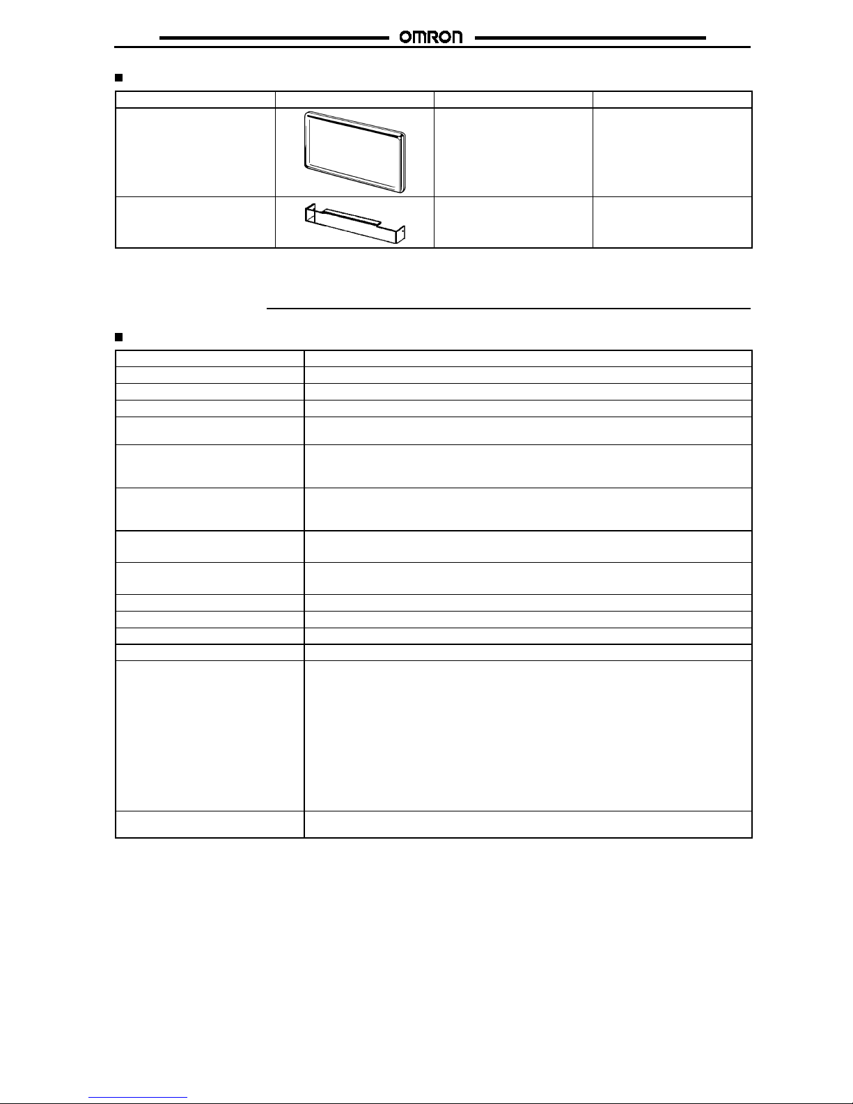
Accessories (Order Separately)
Name Appearance Model Applicable Unit
Water-resistive SoftFront Cover K32-L49SC K3TE
K3TF
K3TL
K3TJ
Terminal Cover K32-L49TC K3TF
K3TL
K3TJ
Note:
1. Use the Mounting Adapters provided with the K3TJ to mount the above accessories.
2. The Terminal Cover is used to protect against electric shock but is not waterproof.
Specifications
Ratings
Supply voltage
100 to 240 VAC (50/60 Hz); 24 VDC (internally insulated)
Operating voltage range
--15% to 10% of supply voltage
Power consumption
Approx. 7.7 VA (max. AC load); approx. 2.8 W (max. DC load)
Insulation resistance
10 M!min. (at 500 VDC) between external terminals and case
Dielectric strength
2.000 VAC for 1 minute between input terminals and power supply
2,000 VAC for 1 minute between external terminals and case
Noise immunity
AC Model:"1,500 V on power supply terminals in normal or common mode
DC Model:"480 V on power supply terminals in normal mode and"1,500 V on power supply
terminals in common mode
Vibration resistance
Malfunction: 10 to 55 Hz, 0.5-mm single amplitude for 10 minutes each in X, Y, and Z
directions
Destruction: 10 to 55 Hz, 0.75-mm single amplitude for 2 hours each in X, Y,and Z directions
Shock resistance
Malfunction: 98 m/s2(10G) for 3 times each in 6 directions.
Destruction: 294 m/s
2
(30G) for 3 times each in 6 directions
Ambient temperature
Operating: --10#Cto55#C (with no icing)
Storage: --20#Cto65#C (with no icing)
Ambient humidity
Operating: 35% to 85% (with no condensation)
Ambient atmosphere
Must be free of corrosive gas
Weight
200 g
Case material
Heat-resistiveABS/PC
EMC
Emission Enclosure: EN55011 Group 1 class A
Emission AC Mains: EN55011 Group 1 class A
EN61000-4-2: 4 kV contact discharge (level 2)
8 kV air dischanrge (level 3)
Immunity RF-interference: ENV50140: 10 V/m (amplitude modulated, 80 MHz to
1GHz)(level3)
10 V/m (pulse modulated, 900 MHz)
Immunity Conducted Disturbance: ENV50141: 10V (0.15 to 80 MHz) (level 3)
Immunity Burst: EN61000-4-4: 2 kV power-line (level 3)
2 kV I/O signal-line (level4)
Approved standards
UL (File No. E4151), CSA (File No. LR67027)
Conforms to EN50081-2 and EN50082-2
Note:
An initial current of approximately 0.25 A will flow for approximately 35 ms the moment the K3TJ is turned on.
Page 3
K3TJ
K3TJ
6
Characteristics
Input signal
DC voltage/current (4 to 20 mA, 1 to 5 V, 0 to 5 V, and 0 to 10 V)
A/D conversion method
Double integral method
Sampling time
0.5 s
Display refresh period
0.5 s
Process value averaging method
Simple average/movement average
No. of process value averaging
operation
1, 2, 4, or 8 times
Max. displayed digits
4 digits (--1,999 to +9,999)
Display
7-segment red or green LED with a character height of 14.2 mm
Decimal display
Selected by the Up and Down Keys and parameter selector
Scaling function
Shift/Scaling adjustment is possible with the Up and Down Keys and parameter selector
Scaling range
--1,999 to +9,999
Zero-limit range
0to99digits
Overflow display
Flashes
Zero-suppress function
Available
External control
Process value hold (by short-circuiting the rear terminals)
Enclosure rating
Front panel: IP51 (see note)
Case: IP20 Refer to IEC
Terminals: IP00
Memory protection
Non-volatile memory (no backup battery is required)
Note:
IP51 is ensured with the Water-resistive Soft Front Cover,whichcanbe ordered separately.Without the Water-resistive Soft Front
Cover, the front panel meets the requirements of IP50 instead.
Measuring Ranges
Measuring range Input impedance Reliability Max. permissible continuous load
Voltage (DC)
1to5VDC 1M
!
"
0.1%rdg"1 digit
"
250 V
g()
0to5VDC 1M
!
"
0.1%rdg"1 digit
"
250 V
0to10VDC 1M
!
"
0.1%rdg"1 digit
"
250 V
Current (DC) 4to20mADC 100
!
"
0.1%rdg"1 digit
"
50 mA
Note:
The measurement accuracy values stated in the above table are guaranteed at an ambient temperature of 255#C.
Parameter List
Parameter name Operation Setting method
Display shift By setting a shift value, the displayed value will be shifted and displayed.
Set with the
Scaling value By setting a scaling value, the input signal will be converted and displayed.
Negative value scaling is possible.
internal
parameter
Decimal point The decimal point position can be selected.
selector an
d
k
ey
input.
Average display Displays the process value for 4 s maximum after a simple average or movement
average process.
input
.
Zero-limit range input Zero will be displayed for any value below the zero-limit value.
2-digit step display Rounds the rightmost digit to 0, 2, 4, 6, or 8.
5-digit step display Rounds the rightmost digit to 0 or 5.
Rightmost digit at 0 Rounds the rightmost digit to 0.
Display brightness adjustment Adjusts the brightness of the display to one of three levels.
Page 4
K3TJ
K3TJ
7
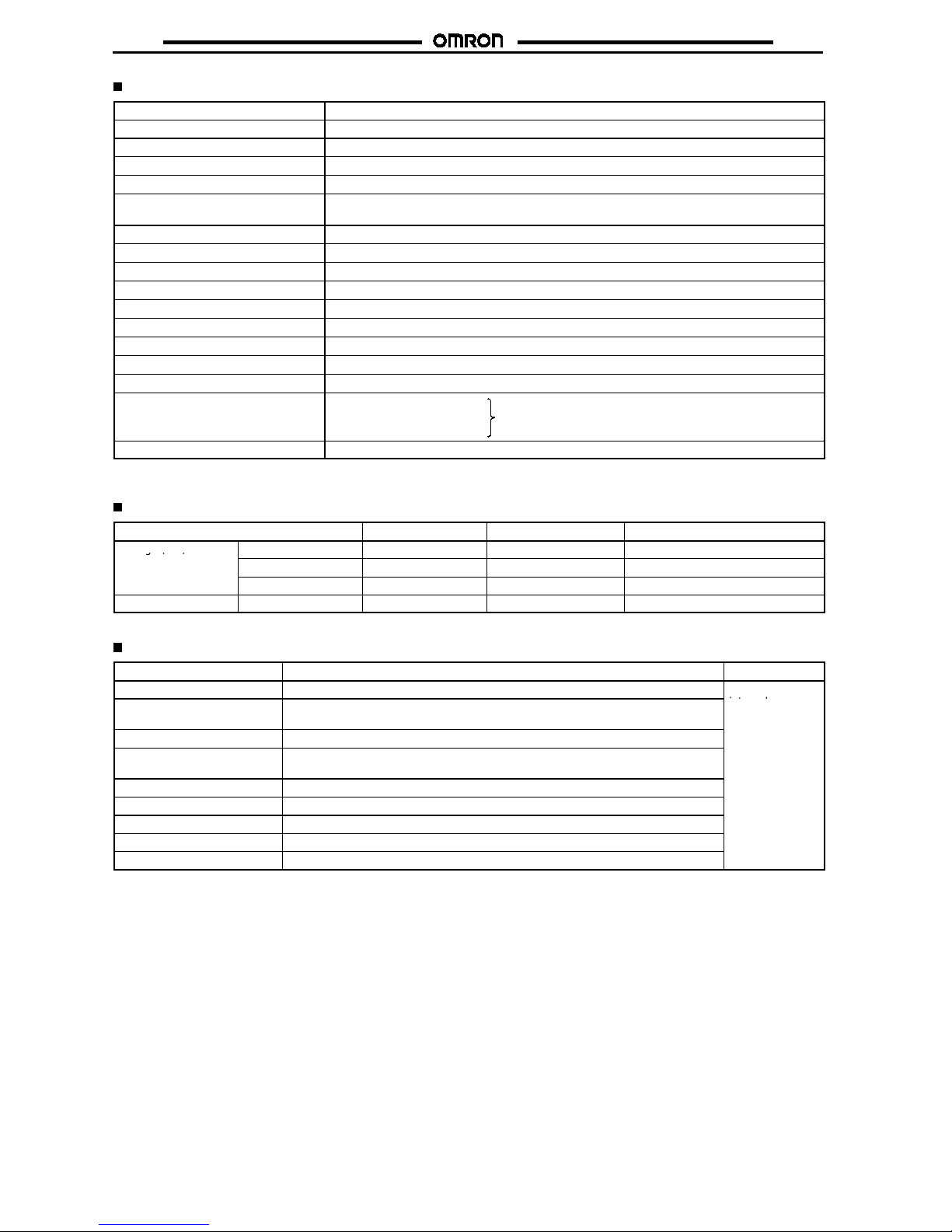
Nomenclature
PV display Unit of measure
Unit Label (Provided)
Select the applicable unit label from the unit label sheet provided with the K3TJ and attach it to the bottom-right side of the display.
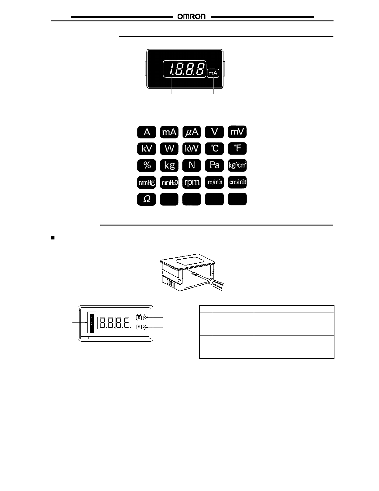
Operation
Removal of Front Panel
Insert a flat-blade screwdriver into the groove on the bottom of the front panel and pull the front panel off.
The following is seen after the front panel is removed.
Parameter
selector
Up Key
Down
Key
1 3456782
ON
No. Name Parameter
1 Parameter
selector
When any one of parameter selector
pins 1 to 8 is set to ON, the
corresponding setting item can be
changed.
2, 3 Up Key, Down
Key
TheUpandDownKeysareusedto
change the set value when the
corresponding parameter selector
pin is set to ON.
Page 5

K3TJ
K3TJ
8
Parameter Selection
Whena parameter selector pin is set toOFF,thecorrespondingsetvaluethathasbeen changed will be stored in thenon-volatile memory.Any
datathathasbeenpreviously set will be kept in the non-volatilememory regardless of whether the K3TJ is turnedonor off. The following table
lists the parameters assigned to parameter selector pins 1 to 8.
13456782
ON
OFF ON
Pin no. Setting
1
Input range
2
Display shift
3
Scaling
4
Decimal point
5
Averaging
6
Zero limit
7
Step display
8
Display brightness
Parameter Setting
The K3TJ is factory-set to display 0 when the minimum input range value is input and display 1,000 when the maximum input range value is
input.
DC Voltage Input Model
Input range
Display
0- to 5-VDC input
0to1000
1- to 5-VDC input
0
t
o
100
0
0- to 10-VDC input
DC Current Input Model
Input range
Display
4 to 20 mA DC input
0to1000
1000
0
max.min.
Display
Input
Adjust the display shift and scaling for the K3TJ
while applying an actual input.
1. Input Range Setting
Select the 0- to 5-V, 1- to 5-V,or 0- to 10-V input range on the DC Voltage Input Model and 4- to 20-mA input range on the DC Current Input
Model.
Example: When selecting the 1- to 5-V input range on the DC Voltage Input Model
Use the Up or Down Keys so that
1- 5
will be displayed.
Up Key or
Down Key
0- 10
1
3
4
5
6
7
8
2
1
3
4
5
6
7
8
2
OFF ON
OFF ON
1- 5
Set parameter selector pin 1 to ON, at which time the
factory-set input range
0- 10
will be displayed.
When
1- 5
is displayed, set parameter selector pin 1 to
OFF to complete the input range setting.
The input range has been changed to
the 1 to 5 V range.
DC Voltage Input Model
Display
Input range
0- 5
0to5VDC
1- 5
1to5VDC
0-10
0to10VDC(factory-set)
DC Current Input Model
Display
Input range
4-20
4to20mADC
Page 6

K3TJ
K3TJ
9
2. Display Shift Adjustment
The display can be shifted within a range of --1,999 to 9,999.
Adjust the display shift while applying an actual input.
Display after shifting
4mAor1V
4- to 20-mA or 1- to 5-V range
Display after shifting
Input
Input
0- to 5-V or 0- to 10-Vrange
1000
1000 + b
1000 + b
1000
b
0
b
0
Example: When shifting from10to
0
Use the Up or Down Key to change the display. To
change the value to0, use the Down Key. The displayed
value will increase automatically if the Up Key is pressed
for 1 s or more and will decrease automatically if the
DownKeyispressedfor1sormore.
Up Key or
Down Key
10
1
3
4
5
6
7
8
2
OFF ON
0
Set parameter selector pin 2 to ON, at which time the
displaywillnot change butadisplayshiftadjustmentwill
be possible.
After0is displayed, set parameter selector pin 2 to OFF
to complete the display shift adjustment.
The display will be shifted
by --10.
1
3
4
5
6
7
8
2
OFF ON
Display
Shift adjustment
Input
0
10
Page 7

K3TJ
K3TJ
10
3. Scaling Adjustment
TheK3TJ is factory-set to display 0to 1,000 for the minimum and maximum input rangevalue. By setting the scaling, the K3TJ can be scaled
within a range of 0 to 9,999 or 0 to --1,999.
Display after scaling
Input
4mAor1V
4- to 20-mA or 1- to 5-V range
Display after scaling
Input
0- to 5-V or 0- to 10-V range
1000
1000 x a
1000 x a
1000
0
0
Example: When adjusting the factory set value
800
to a scaling value of
1200
Adjust the scaling while applying an actual input.
Use the Up or Down Key to change the display. To
change the value to
1200
, use the Up Key. The displayed
value will increase automatically if the Up Key is pressed
for 1 s or more and will decrease automatically if the
DownKeyispressedfor1sormore.
Up Key or
Down Key
800
1
3
4
5
6
7
8
2
OFF ON
1200
Set parameter selector pin 3 to ON, at which time the
display will not change but a scalingadjustment willbe
possible.
After
1200
is displayed, set parameter selector pin 3 to
OFF to complete the scaling adjustment
The scaling has been changed.
1
3
4
5
6
7
8
2
OFF ON
Display
Scaling
adjustment
Input
1200
800
0
Display Shift Setting and Scaling Operation
In the following example, 4 to 20 mA is scaled to be 100 to 1,000.
Display
Factory set
Shift adjustment
4 mA is input
Input
Display
Span adjustment
Input
20 mA is input
0
100
1000
1100
20 mA
0
100
1000
1100
4mA
1. Shift Adjustment 2. Scaling Adjustment
Note:
1. Atthe time of scaling adjustment, the starting point for changing the inclinationof the straight line will bethe minimum value of the
input range. Therefore, when using only a part of the input range, repeat shifting and scaling adjustments several times.
2. TurntheK3TJoffandon while pressing both theUpandDown Keys so that theK3TJ’sshiftingandscalingsettingswillreturntothe
ones preset before shipping.
Page 8

K3TJ
K3TJ
11
4. Decimal Point Setting
The decimal is set to the desired position.
Use the Up or Down Key to change the
decimal point position.
Up Key or
Down Key
1
3
4
5
6
7
8
2
OFF ON
Setparameterselectorpin4 toONtoset
the decimal.
After changing the decimal point, set
parameter selector pin 4 to OFF to
complete the new decimal point setting.
1
3
4
5
6
7
8
2
OFF ON
Display Decimal point
0000
No decimal point (factory-set)
000.0
Next to 101digit on the left
00.00
Next to 102digit on the left
0.000
Next to 103digit on the left
Note:
Inthecaseof a range of --0.001 to --0.999,
-.001to-.999
will
be displayed.
5. Average Process Setting
There are two ways to input signals: the simple average processing method and the movement average processing method.
Inthe simpleaverageprocessingmethod,the meanvalueis displayedaftersamplingn times. Thismethodis effectivewhentheuser requiresa
long display refresh period.
Inmovementaverageprocessingmethod,the samplingdata obtained fromsamplingntimesincludingthepresent samplingoperation is aver-
aged and displayed. This method is effective for removing the periodical noise overlapped with the input signals.
Use the Up or Down Key to change the
average processing method.
Up Key or
Down Key
1
3
4
5
6
7
8
2
OFF ON
Setparameterselectorpin5 toONtoset
the average processing.
Afterselecting the average processing
method,setparameterselectorpin 5to
OFF to complete the average process
setting.
1
3
4
5
6
7
8
2
OFF ON
Display Average processing
1
No average processing is possible (factory set)
a- 2
Simple average processing by sampling twice
a- 4
Simple average processing by sampling four times
a- 8
Simple average processing by sampling eight
times
b- 2
Movement average processing by sampling twice
b- 4
Movement average processing by sampling four
times
b- 8
Movement average processing by sampling eight
times
Page 9

K3TJ
K3TJ
12
6. Zero Limit Setting
Zero limit setting enables the K3TJ to display zero for any value less than the set value. This is effective if the user needs to have the K3TJ
displayzeroinsteadof anegativevalueor theuserneeds tohavetheK3TJ display zero fortheminimuminputrange value. Thesetting rangeis
from 00 to 99. When no zero limit is set,
off
will be displayed.
Use the Up or Down Key to input the
zero limit value. The displayed value
will increase automatically if the Up Key
is pressed for 1 s or more and will decrease automatically if the Down Key is
pressed for 1 s or more.
Up Key or
Down Key
1
3
4
5
6
7
8
2
OFF ON
Setparameterselector pin6toONtoset
the zero limit.
Aftersetting the zero limit,setparameter selector pin 6 to OFF to complete
the zero limit setting.
1
3
4
5
6
7
8
2
OFF ON
Display Zero limit setting
99
to
00
Zero limit setting range
off
No zero limit (factory set)
Zero Limit Setting Range
Display
Zero limit
setting
value
Input
7. Step Display Setting
Step display setting is used to change the step of the displayed rightmost digit changes. This setting is effective if the input signal repeatedly
displays
999
and
1000
and is difficult to read. The following table shows the step display patterns.
Use the Up or Down Key to select the
display pattern.
Up Key or
Down Key
1
3
4
5
6
7
8
2
OFF ON
Setparameter selector pin 7 toONtoset
thestepdisplay.
After selecting the display pattern, set
parameter selector pin 7 to OFF to
complete the step display setting.
1
3
4
5
6
7
8
2
OFF ON
Display Step display pattern
1
No step display (factory set)
2
With every two digits
5
With every five digits
10
With every ten digits (the rightmost digit is fixed to
0)
Step Display Parameter
The display step of the rightmost digit can be selected.
1 2 3 4 5 6 7 8 9 10 11 12 13 140
0
2 4 6 8 10 12 14
51015
010
Input value
2-digit step
5-digit step
Fixedtobezero
Displayed
value
0
Page 10

K3TJ
K3TJ
13
8. Display Brightness Adjustment
It is possible to change the display brightness in three steps.
Use the Up or Down Key to select the
proper display brightness.
Up Key or
Down Key
1
3
4
5
6
7
8
2
OFF ON
Set parameter selector pin 8 to ON, at
which time the display will not change
but a display brightness adjustment will
be possible.
After the display brightness has been
selected, set parameter pin 8 to complete the display brightness setting.
1
3
4
5
6
7
8
2
OFF ON
Error Message
Refer to the following table in the case of an error.
Display
Cause Remedy
e01
The internal memory has malfunctioned.
Turn the K3TJ OFF and ON. If the error condition of the
e02
The non-volatile memory has malfunctioned.
K3TJ does not change, consult your OMRON representative.
e03
The calibration value stored in the non-volatile memory has
been corrupted.
e10
The input range set value stored in the non-volatile memory
has been corrupted.
Select the input range again according to the input range
setting procedure.
e11
The shift value stored in the non-volatile memory has been
corrupted.
Execute display shift again according to the display shift
adjustment procedure.
e12
The scaling value stored in the non-volatile memory has
been corrupted.
Execute scaling again according to the scaling adjustment
procedure.
e13
The decimal point set value stored in the non-volatile
memory has been corrupted.
Set the decimal point again according to the decimal point
setting procedure.
e14
The average processing set value stored in the non-volatile
memory has been corrupted.
Select average processing again according to the average
processing setting procedure.
e15
The zero limit value stored in the non-volatile memory has
been corrupted.
Set the zero limit value again according to the zero limit
value setting procedure.
e16
The step value stored in the non-volatile memory has been
corrupted.
Set the step display pattern again according to the step
display setting procedure.
e17
The brightness setting value in the non-volatile memory has
been corrupted.
Set the display brightness again according to the display
brightness adjustment procedure.
Note:
Turnthe K3TJ OFFandONwhile pressing both the UpandDownKeys so that the K3TJ’s shifting and scaling settingswillreturn to the
ones preset before shipping.
Page 11

K3TJ
K3TJ
14
Dimensions
Note:
All units are in millimeters unless otherwise indicated.
Panel Cutouts
75 min.
120 min.
LED Display Character Size
14.2 mm
7.8 mm
45
+0.6
-- 0
92
+0.8
-- 0
66
98
92
96
48
3.5
45
Installation
External Connections
24 VDC
HOLD GND
GND0to10VDC
0to5VDC
1to5VDC
4to20mADC
INPUT POWER
321 4 5 6 7 8 9
100to240VAC
Note:
Terminals 3 and 6 are connected internally. The power supply terminals are insulated from other circuits.
Connection Example with Inverter
+
--
E
0to10VDC
1
GND
3
3G3jV
8888
Analog
monitor
Analog output
K3TJ
R
S
T
R
S
T
U
V
W
IM
Three-phase
power supply
Circuit breaker
Inverter ’s
internal
circuitry
Page 12

K3TJ
K3TJ
15
Precautions
Mounting
Recommended panel thickness is 1 to 3.2 mm.
Mount the K3TJ by attaching the mounting bracket supplied as an
accessory from the rear of the K3TJ. Turn each mounting screw
clockwise and tighten it to a torque of 5 kgf$cm (0.49N$m).
Mount the K3TJ as horizontally as possible.
Never use the K3TJ in locations where corrosive gas (particularly
sulfuric or ammonia gas) exists.
Avoiduse of the K3TJ inlocations subject to severe shock orvibra-
tion, excessive dust, or excessive moisture.
Select mounting locations where the ambient operating tempera-
ture is -- 10#Cto55#C.
Others
Whenselecting parameters or making settings,thefrontpanelcovershould be removed. Do not touchpartsother than the DIP switch
andkeys with yourhandorametalobject, especiallywhentheK3TJ
is turned ON.
Page 13

K3TJ
K3TJ
16
OMRON Corporation
Systems Components Division
28th Fl., Crystal TowerBldg.
1-2-27, Shiromi, Chuo-ku,
Osaka 540 Japan
Phone: 06-949-6012 Fax: 06-949-6021
ALL DIMENSIONS SHOWN ARE IN MILLIMETERS.
To convert millimeters into inches, multiply by 0.03937. To convert grams into ounces, multiply by 0.03527.
Cat. No. N080-E1-1C
In the interest of product improvement, specifications are subject to change without notice.
Printed in Japan
1096-0.5M (0694)
a
 Loading...