

Page 1
Cat. No. N093-E1-1A
K3NR
Frequency/Rate Meter
Page 2

K3NR Frequency/Rate Meter
Operation Manual
Revised February 2001
Page 3

iv
Page 4

!
!
!
v
Notice:
OMRON products are manufactured for use according to proper procedures by a qualified operator
and only for the purposes described in this manual.
The following conventions are used to indicate and classify precautions in this manual. Always heed
the information provided with them. Failure to heed precautions can result in injury to people or damage to the product.
DANGER Indicates information that, if not heeded, is likely to result in loss of life or serious injury.
WARNING Indicates information that, if not heeded, could possibly result in loss of life or serious injury.
Caution Indicates information that, if not heeded, could result in relatively serious or minor injury, dam-
age to the product, or faulty operation.
OMRON Product References
All OMRON products are capitalized in this manual. The word “Unit” is also capitalized when it refers
to an OMRON product, regardless of whether or not it appears in the proper name of the product.
The abbreviation “Ch,” which appears in some displays and on some OMRON products, often means
“word” and is abbreviated “Wd” in documentation in this sense.
The abbreviation “PC” means Programmable Controller and is not used as an abbreviation for anything else.
Visual Aids
The following headings appear in the left column of the manual to help you locate different types of
information.
Note Indicates information of particular interest for efficient and convenient operation
of the product.
1, 2, 3... 1. Indicates lists of one sort or another, such as procedures, checklists, etc.
OMRON, 1998
All rights reserved. No part of this publication may be reproduced, stored in a retrieval system, or transmitted, in any
form, or by any means, mechanical, electronic, photocopying, recording, or otherwise, without the prior written permission of OMRON.
No patent liability is assumed with respect to the use of the information contained herein. Moreover, because OMRON is
constantly striving to improve its high-quality products, the information contained in this manual is subject to change
without notice. Every precaution has been taken in the preparation of this manual. Nevertheless, OMRON assumes no
responsibility for errors or omissions. Neither is any liability assumed for damages resulting from the use of the information contained in this publication.
Page 5

vi
Page 6

TABLE OF CONTENTS
vii
PRECAUTIONS xi. . . . . . . . . . . . . . . . . . . . . . . . . . . . . . . . .
1 General Precautions xii. . . . . . . . . . . . . . . . . . . . . . . . . . . . . . . . . . . . . . . . . . . . . . . . . . . . . . . . . .
2 Safety Precautions xii. . . . . . . . . . . . . . . . . . . . . . . . . . . . . . . . . . . . . . . . . . . . . . . . . . . . . . . . . . .
3 Application Precautions xii. . . . . . . . . . . . . . . . . . . . . . . . . . . . . . . . . . . . . . . . . . . . . . . . . . . . . .
4 Noise Prevention xiii. . . . . . . . . . . . . . . . . . . . . . . . . . . . . . . . . . . . . . . . . . . . . . . . . . . . . . . . . . . .
SECTION 1
Introduction 1. . . . . . . . . . . . . . . . . . . . . . . . . . . . . . . . . . . .
1-1 Features 2. . . . . . . . . . . . . . . . . . . . . . . . . . . . . . . . . . . . . . . . . . . . . . . . . . . . . . . . . . . . . . .
1-2 Front of the Meter 4. . . . . . . . . . . . . . . . . . . . . . . . . . . . . . . . . . . . . . . . . . . . . . . . . . . . . . .
1-3 Rear of the Meter 7. . . . . . . . . . . . . . . . . . . . . . . . . . . . . . . . . . . . . . . . . . . . . . . . . . . . . . . .
1-4 Modes 8. . . . . . . . . . . . . . . . . . . . . . . . . . . . . . . . . . . . . . . . . . . . . . . . . . . . . . . . . . . . . . . . .
1-5 Communications Function 9. . . . . . . . . . . . . . . . . . . . . . . . . . . . . . . . . . . . . . . . . . . . . . . . .
SECTION 2
Setup 11. . . . . . . . . . . . . . . . . . . . . . . . . . . . . . . . . . . . . . . . . .
2-1 Mounting 12. . . . . . . . . . . . . . . . . . . . . . . . . . . . . . . . . . . . . . . . . . . . . . . . . . . . . . . . . . . . . .
2-2 Input Block 13. . . . . . . . . . . . . . . . . . . . . . . . . . . . . . . . . . . . . . . . . . . . . . . . . . . . . . . . . . . . .
2-3 Output Board 16. . . . . . . . . . . . . . . . . . . . . . . . . . . . . . . . . . . . . . . . . . . . . . . . . . . . . . . . . . .
SECTION 3
Operating Modes 21. . . . . . . . . . . . . . . . . . . . . . . . . . . . . . . .
3-1 Rotational/Circumferential Speed: F1 22. . . . . . . . . . . . . . . . . . . . . . . . . . . . . . . . . . . . . . . .
3-2 Absolute Ratio: F2 25. . . . . . . . . . . . . . . . . . . . . . . . . . . . . . . . . . . . . . . . . . . . . . . . . . . . . . .
3-3 Error Ratio: F3 28. . . . . . . . . . . . . . . . . . . . . . . . . . . . . . . . . . . . . . . . . . . . . . . . . . . . . . . . . .
3-4 Rotational Difference: F4 31. . . . . . . . . . . . . . . . . . . . . . . . . . . . . . . . . . . . . . . . . . . . . . . . . .
3-5 Flow Rate Ratio: F5 34. . . . . . . . . . . . . . . . . . . . . . . . . . . . . . . . . . . . . . . . . . . . . . . . . . . . . .
3-6 Passing Time: F6 37. . . . . . . . . . . . . . . . . . . . . . . . . . . . . . . . . . . . . . . . . . . . . . . . . . . . . . . .
3-7 Pulse Counting: F7 40. . . . . . . . . . . . . . . . . . . . . . . . . . . . . . . . . . . . . . . . . . . . . . . . . . . . . . .
SECTION 4
Parameter Setting 45. . . . . . . . . . . . . . . . . . . . . . . . . . . . . . .
4-1 Overview 46. . . . . . . . . . . . . . . . . . . . . . . . . . . . . . . . . . . . . . . . . . . . . . . . . . . . . . . . . . . . . .
4-2 Setting Mode 47. . . . . . . . . . . . . . . . . . . . . . . . . . . . . . . . . . . . . . . . . . . . . . . . . . . . . . . . . . .
4-3 Protect Mode 88. . . . . . . . . . . . . . . . . . . . . . . . . . . . . . . . . . . . . . . . . . . . . . . . . . . . . . . . . . .
SECTION 5
Operations in RUN Mode 99. . . . . . . . . . . . . . . . . . . . . . . . .
5-1 Displaying and Changing Setting Values 100. . . . . . . . . . . . . . . . . . . . . . . . . . . . . . . . . . . . . .
5-2 Displaying and Resetting of Maximum and Minimum Values
(Operating Modes F1 to F6) 103. . . . . . . . . . . . . . . . . . . . . . . . . . . . . . . . . . . . . . . . . . . . . . . .
5-3 External Input Signals 104. . . . . . . . . . . . . . . . . . . . . . . . . . . . . . . . . . . . . . . . . . . . . . . . . . . .
SECTION 6
Useful Functions 107. . . . . . . . . . . . . . . . . . . . . . . . . . . . . . . . .
6-1 Teaching Function 108. . . . . . . . . . . . . . . . . . . . . . . . . . . . . . . . . . . . . . . . . . . . . . . . . . . . . . .
6-2 Output Test 112. . . . . . . . . . . . . . . . . . . . . . . . . . . . . . . . . . . . . . . . . . . . . . . . . . . . . . . . . . . . .
6-3 Maintenance Mode 113. . . . . . . . . . . . . . . . . . . . . . . . . . . . . . . . . . . . . . . . . . . . . . . . . . . . . . .
Page 7

TABLE OF CONTENTS
viii
SECTION 7
BCD Output 115. . . . . . . . . . . . . . . . . . . . . . . . . . . . . . . . . . . .
7-1 Connectors 116. . . . . . . . . . . . . . . . . . . . . . . . . . . . . . . . . . . . . . . . . . . . . . . . . . . . . . . . . . . . .
7-2 Timing Charts 119. . . . . . . . . . . . . . . . . . . . . . . . . . . . . . . . . . . . . . . . . . . . . . . . . . . . . . . . . . .
SECTION 8
Troubleshooting 121. . . . . . . . . . . . . . . . . . . . . . . . . . . . . . . . .
8-1 Items to Be Checked First 122. . . . . . . . . . . . . . . . . . . . . . . . . . . . . . . . . . . . . . . . . . . . . . . . .
8-2 Display 122. . . . . . . . . . . . . . . . . . . . . . . . . . . . . . . . . . . . . . . . . . . . . . . . . . . . . . . . . . . . . . . .
Appendices
A Specifications 125. . . . . . . . . . . . . . . . . . . . . . . . . . . . . . . . . . . . . . . . . . . . . . . . . . . . . . . . . . . . . .
B Estimated Frequency Calculation 129. . . . . . . . . . . . . . . . . . . . . . . . . . . . . . . . . . . . . . . . . . . . . .
C List of Settings 131. . . . . . . . . . . . . . . . . . . . . . . . . . . . . . . . . . . . . . . . . . . . . . . . . . . . . . . . . . . . .
D Available Models 133. . . . . . . . . . . . . . . . . . . . . . . . . . . . . . . . . . . . . . . . . . . . . . . . . . . . . . . . . . .
E Available Parameters 135. . . . . . . . . . . . . . . . . . . . . . . . . . . . . . . . . . . . . . . . . . . . . . . . . . . . . . . .
F Setting Examples 139. . . . . . . . . . . . . . . . . . . . . . . . . . . . . . . . . . . . . . . . . . . . . . . . . . . . . . . . . . .
Index 141. . . . . . . . . . . . . . . . . . . . . . . . . . . . . . . . . . . . . . . . . .
Revision History 145. . . . . . . . . . . . . . . . . . . . . . . . . . . . . . . . .
Page 8

ix
About this Manual:
This manual describes the installation and operation of the K3NR Frequency/Rate Meter and includes the
sections described below.
Please read this manual carefully and be sure you understand the information provided before attempting
to install and operate the K3NR.
Section 1 describes the functions of the K3NR. The main components are also described.
Section 2 provides instructions required for mounting and wiring the K3NR.
Section 3 provides instructions for setting the parameters of the K3NR.
Section 4 provides instructions for operating the K3NR in RUN mode.
Section 5 provides information on the teaching function, output test, and maintenance mode.
Section 6 provides information on the use of the K3NR with the BCD Output Board.
Section 7 provides information for troubleshooting the K3NR
The Appendices provide specifications, a list of settings, a list of standard models, and a list of available
menu items.
WARNING Failure to read and understand the information provided in this manual may result in
personal injury or death, damage to the product, or product failure. Please read each
section in its entirety and be sure you understand the information provided in the section
and related sections before attempting any of the procedures or operations given.
!
Page 9

xi
PRECAUTIONS
This section provides precautions for using the K3NR Frequency/Rate Meter and related devices.
The information contained in this section is important for the safe and reliable application of the K3NR. You must read
this section and understand the information contained before attempting to set up or operate the K3NR.
1 General Precautions xii. . . . . . . . . . . . . . . . . . . . . . . . . . . . . . . . . . . . . . . . . . . . . . . . . . . . . . . . . . .
2 Safety Precautions xii. . . . . . . . . . . . . . . . . . . . . . . . . . . . . . . . . . . . . . . . . . . . . . . . . . . . . . . . . . . .
3 Application Precautions xii. . . . . . . . . . . . . . . . . . . . . . . . . . . . . . . . . . . . . . . . . . . . . . . . . . . . . . . .
4 Noise Prevention xiii. . . . . . . . . . . . . . . . . . . . . . . . . . . . . . . . . . . . . . . . . . . . . . . . . . . . . . . . . . . . .
Page 10

!
!
3SectionApplication Precautions
xii
1 General Precautions
The user must operate the product according to the performance specifications
described in the operation manuals.
Before using the product under conditions which are not described in the manual
or applying the product to nuclear control systems, railroad systems, aviation
systems, vehicles, combustion systems, medical equipment, amusement machines, safety equipment, and other systems, machines, and equipment that
may have a serious influence on lives and property if used improperly, consult
your OMRON representative.
Be sure to read this manual before attempting to use the product and keep this
manual close at hand for reference during operation.
2 Safety Precautions
WARNING Never attempt to disassemble any Units while power is being supplied. Doing so
may result in serious electrical shock or electrocution.
WARNING Never touch any of the terminals while power is being supplied. Doing so may
result in serious electrical shock or electrocution.
3 Application Precautions
Observe the following precautions when using the product.
• Always use the power supply voltage specified in the specifications.
• Do not use the product in locations subject to flammable gases or combustible
objects.
• Be sure to confirm terminal names when wiring.
• Be sure to tighten the screws on the terminal blocks.
Observe the following precautions when mounting the product.
• Mount the product on level surfaces.
• Mount the product on a panel which has a thickness of 1 to 3.2 mm.
Do not mount the product in the following places.
• Locations subject to strong shock or vibration.
• Locations subject to temperature or humidity exceeding the rated levels or
where icing is liable to occur.
• Locations subject to dust.
• Locations subject to corrosive gases (particularly sulfuric gases or ammonium
gases).
• Locations subject to direct sunlight or outdoor conditions.
• Locations near devices (high-frequency welders or high-frequency sewing
machines) that produce high-frequency noise.
Page 11
4SectionNoise Prevention
xiii
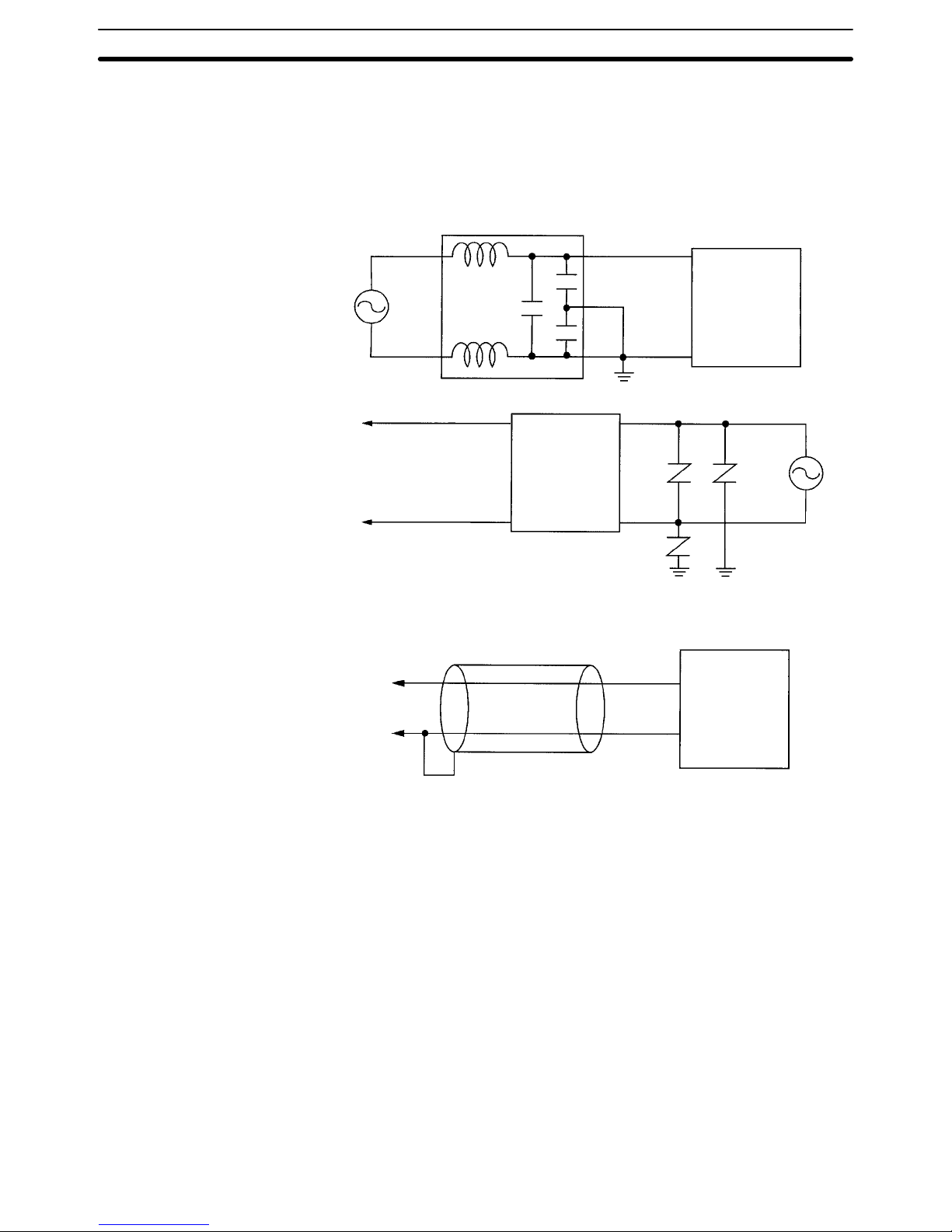
4 Noise Prevention
Provide the following countermeasures when using the product in an environment where the product is exposed to noise.
• Countermeasures for protecting the product against high-frequency noise or
abnormal voltages.
Line filter
Frequency/Rate
Meter
Power
input
Power
input
Signal
input
+++
–
Frequency/Rate
Meter
• Countermeasures for protecting the product against inductive noise produced
from the input line.
2-conductor shield wire
+
Frequency/Rate
Meter
–
Page 12

1
SECTION 1
Introduction
This section describes the functions of the K3NR. The main components are also described. Refer to the remaining sections of
this manual for the operation of the K3NR and its menus in detail.
1-1 Features 2. . . . . . . . . . . . . . . . . . . . . . . . . . . . . . . . . . . . . . . . . . . . . . . . . . . . . . . . . . . . . . . .
1-2 Front of the Meter 4. . . . . . . . . . . . . . . . . . . . . . . . . . . . . . . . . . . . . . . . . . . . . . . . . . . . . . . .
1-3 Rear of the Meter 7. . . . . . . . . . . . . . . . . . . . . . . . . . . . . . . . . . . . . . . . . . . . . . . . . . . . . . . . .
1-4 Modes 8. . . . . . . . . . . . . . . . . . . . . . . . . . . . . . . . . . . . . . . . . . . . . . . . . . . . . . . . . . . . . . . . . .
1-5 Communications Function 9. . . . . . . . . . . . . . . . . . . . . . . . . . . . . . . . . . . . . . . . . . . . . . . . . .
Page 13
2
1-1 Features
The K3NR Frequency/Rate Meter displays desired values after converting input
pulses.
The K3NR has the following functions.
Operating mode Function
1 Displays rotational or circumferential speed of a single input.
2 to 5 Displays the calculation results of two rotational inputs.
6 Displays passing time calculated from the frequency and process length of a single input.
7 Counts and displays the number of pulses.
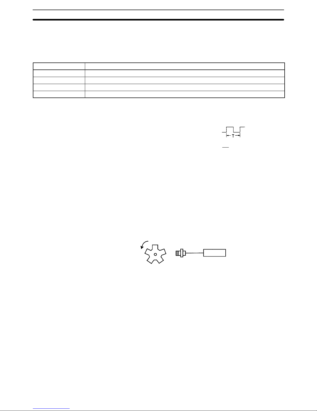
Measurement The internal system clock counts the ON/OFF time (T) of sensor input or other
input and automatically calculates the frequency. The number of revolutions is
calculated from the result of the frequency multiplied by 60.
Sensor input pulse ON/OFF time (T) =
Frequency (f) =
T
1
• Rotational speed (rpm) = f x 60
• Circumferential speed = Circumference x revolutions
• Passing time = Length of processing/Circumferential speed
• Pulse counting
If there is any pulse input, the input will be automatically converted numerically
and displayed.
Prescaling The number of input pulses is converted into a desired value.
Enables the K3NR to display the revolutions or rotational speed. It is necessary
to multiply the number of pulses per revolution or circumference by a certain factor. This factor is called the prescaling value.
Example:
Proximity Sensor
K3NR
rpm = f x 60 x a
f: Input pulse frequency (number of pulses per second)
a: Prescale value
If there are five pulses per rotation, the accurate rotational
speed can be calculated if a = 1/5 (– 0.2=2 x 10
–1
).
Comparison output patterns can be selected from the standard, level, or zone
output depending on the application.
Refer to Comparative Output Patterns, page 80.
Refer to Linear Output Range, page 83.
BCD Output A digital data output format where every four binary bits is numerically equivalent
to one decimal digit.
Refer to Section 7 BCD Output.
Refer to the Communications Manual.
HOLD is an external input which is used to stop the A/D process and freeze the
display. The comparative, linear, and BCD outputs are also retained.
Refer to 5-3 External Input Signals for details.
Comparative Output
Selection
Linear Output
Communications Output
HOLD
Features Section 1-1
Page 14

3
RESET is an external input to reset the present max./min. values and counting
values. The process value when the RESET is ON is set as the maximum and
minimum values. The counting value is reset to zero. The max./min. values and
counting values can be reset using the front panel keys.
Refer to pages 104 and 105.
Teaching The K3NR is provided with a teaching function that can set an actual measured
value as a setting value without key input.
This function is useful for setting parameters while checking the operating status
of the K3NR.
The teaching function can be used to set the set and prescaling values. It can be
also used to set the linear output range of the K3NR with a Linear Output Board.
Refer to 6-1 Teaching Function for details.
Output Test This function is convenient for checking a system to which the K3NR is con-
nected, especially when some inputs cannot be operated. The K3NR simulates
an input to check the output conditions.
Refer to 6-2 Output test for details.
Hysteresis The established setting value includes a hysteresis setting to prevent “chatter-
ing” of the output when the measured value fluctuates in the vicinity of the setting
values.
Hysteresis is enabled when the measured value is starts to become smaller than
the HH and H setting values and larger than the LL and L setting values.
Refer to Hysteresis, page 78.
Startup Compensation Time The startup compensation time parameter keeps the measurement operation
from sending an unnecessary output corresponding to instantaneous, fluctuating input from the moment the K3NR is turned ON until the end of the preset period.
Refer to Startup Compensation Time, page 74.
Remote/Local Selection The K3NR can be operated remotely through a host computer or locally with key
inputs.
Remote Mode: For programming remotely by downloading setup parameters
from a host computer via RS-232C, RS-485, or RS-422.
Local Mode: Programming is performed with the front panel key input.
Refer to Remote/Local Programming, page 86.
Setting process time for averaging measured value prevents the display from
fluctuating due to unstable input.
Refer to Process Time for Averaging Measured Value, page 72.
Auto-Zero Time The input pulse frequency does not drop to zero perfectly due to the estimated
frequency calculation of the K3NR. Therefore, the K3NR has a function to calibrate the frequency to zero forcibly should no input pulse be received for a certain period. The period during which no pulse is received before the K3TR sets
the frequency to zero is called “auto-zero time.”
Refer to page 62.
RESET
Process Time for Averaging
Measured Value
Features Section 1-1
Page 15
4
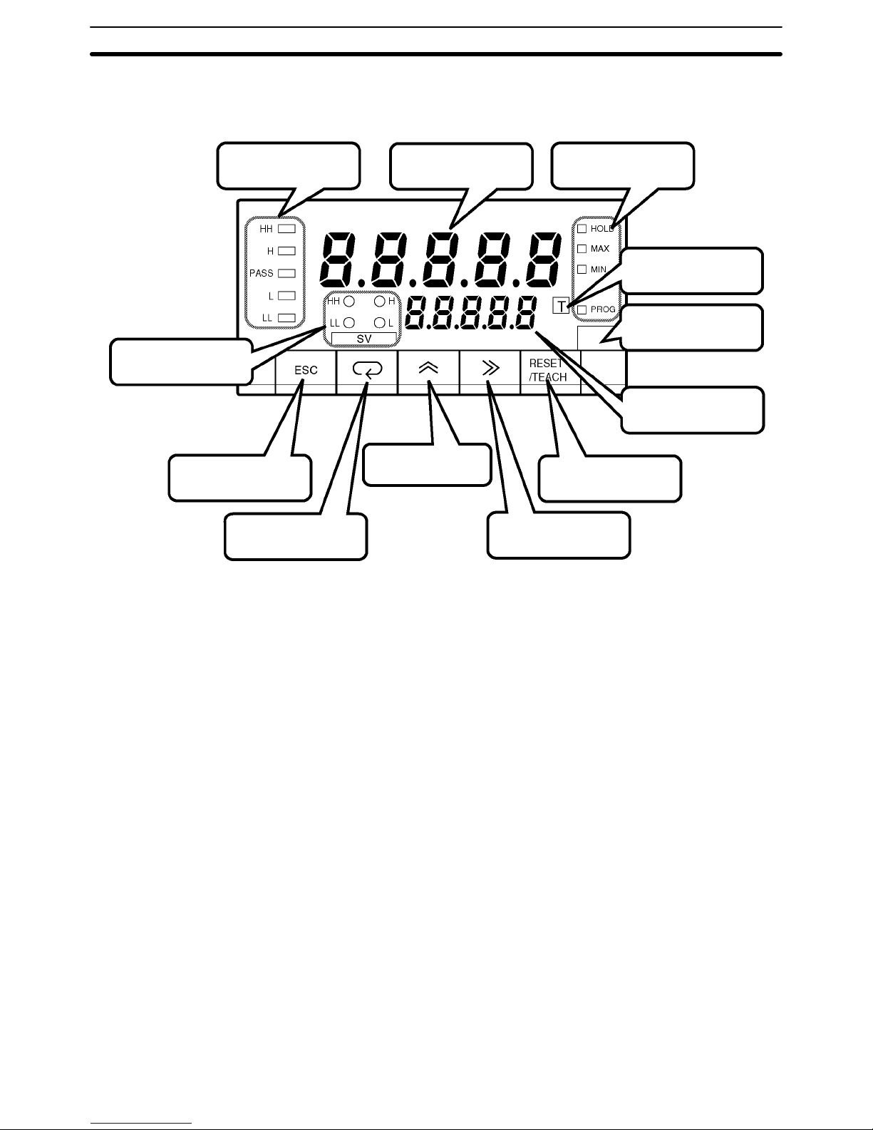
1-2 Front of the Meter
Comparative output
status indicators
PV display
Mode Key
Status indicators
SV display status
indicators
Teaching indicator
Unit of measure
SV display
Shift Key
Escape Key
Up Key
RESET/TEACH Key
Five-digit (–19999 to 99999), seven-segment, 14.2-mm-high LED display with a
programmable decimal point.
The displays show the process value, maximum value, minimum value, operations/parameters when setting, and error messages.
PV Display K3NR-jjjA Basic Model
RUN Mode: Displays the process, maximum, and minimum values. Also
displays setting values while the SV indicator is lit. When
changing a value, all digits other than those that can be set become dimmer.
Setting Mode: Displays the menu, parameter, or setting value. When chang-
ing a value, all digits other than those that can be set become
dimmer.
K3NR-jjjC Set Value LED Display Model
RUN Mode: Displays the process, maximum, and minimum values.
Setting Mode: Displays the menu and parameters.
RUN Mode: Displays comparative set values. When changing a value, all
digits other than those that can be set become dimmer.
Setting Mode: Displays setting values. When changing a value, all digits other
than those that can be set become dimmer.
Indicates the status of the comparative output.
SV Display (Setting value
LED Display Models Only)
Comparative Output Status
Indicators
Front of the Meter
Section 1-2
Page 16
5
Status Indicators HOLD Indicator
Lit when the HOLD input signal is ON.
MAX Indicator
Lit when the value displayed on the PV display is the maximum value.
MIN Indicator
Lit when the value displayed on the PV display is the minimum value.
PROG Indicator
Lit when the setting mode menu is displayed. The indicator flashes while parameters are displayed.
Teaching Indicator Lit when displayed parameters can be set in teaching operation. The indicator
flashes when the process value is indicated as a setting value.
SV Display Status Indicators Indicates which set value is on the PV or SV display.
Unit of Measure Attach the appropriate label showing the unit of measure (enclosed).
Used to select the process, maximum, or minimum value to be displayed on the
PV display in RUN mode.
Process value Maximum value Minimum value
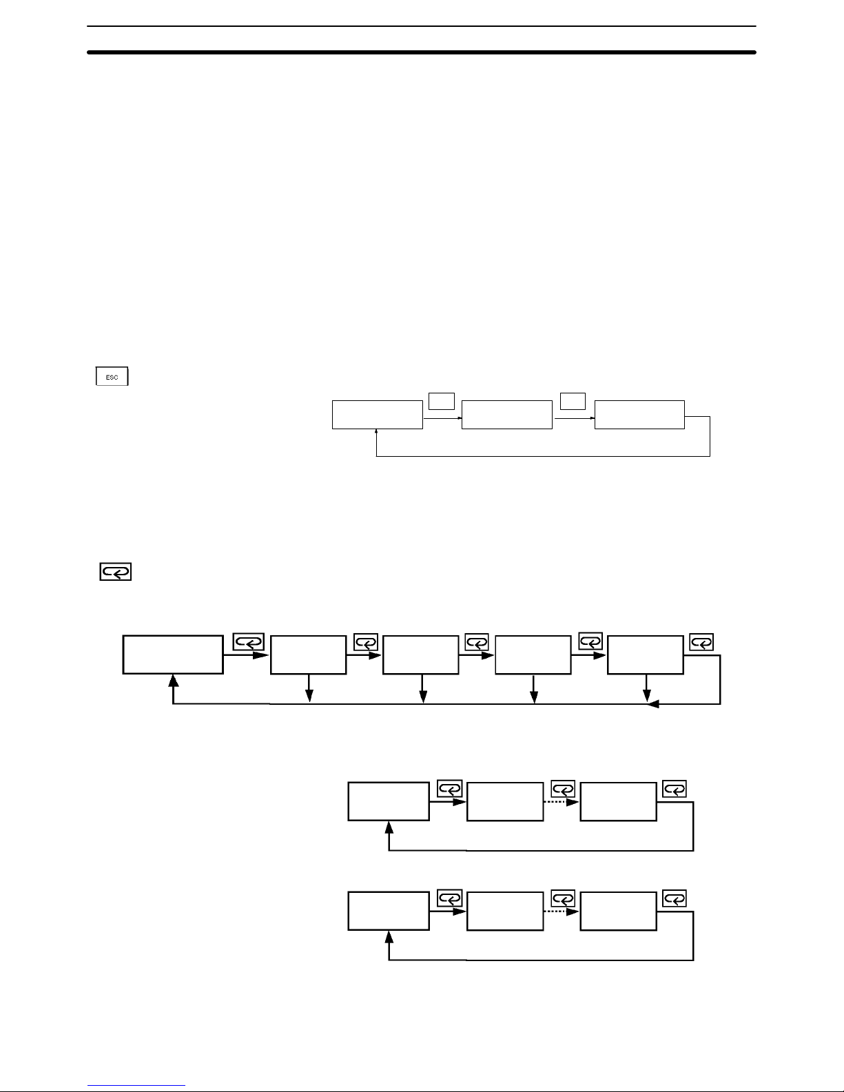
ESC ESC
Used to return from the setting, protect, or maintenance mode to the RUN mode.
This key is also used to return to the previous operation during the setting, protect, or maintenance mode.
Displays a setting value (out of HH, H, L, and LL setting values in this order) on
the PV display in RUN mode when this key is pressed. Unless another operation
key is pressed within five seconds after this key has been pressed, the display
automatically changes to the one for process values.
Process value
Maximum value
Minimum value
HH is lit.
HH setting
value
H setting
value
L setting
value
LL setting
value
H is lit. L is lit. LL is lit.
No key input
for 5 seconds.
No key input
for 5 seconds.
No key input
for 5 seconds.
No key input
for 5 seconds.
In the RUN mode, this button terminates the measurement process and allows
you to enter the setting mode, advancing through the menus and parameters.
Menu 1 Menu 2
Menu n
Parameter 1 Parameter 2 Parameter n
In the setting mode, this button will store changes in the non-volatile memory
while at the same time advancing the display to the next menu item.
Escape Key
Mode Key
Front of the Meter
Section 1-2
Page 17
6
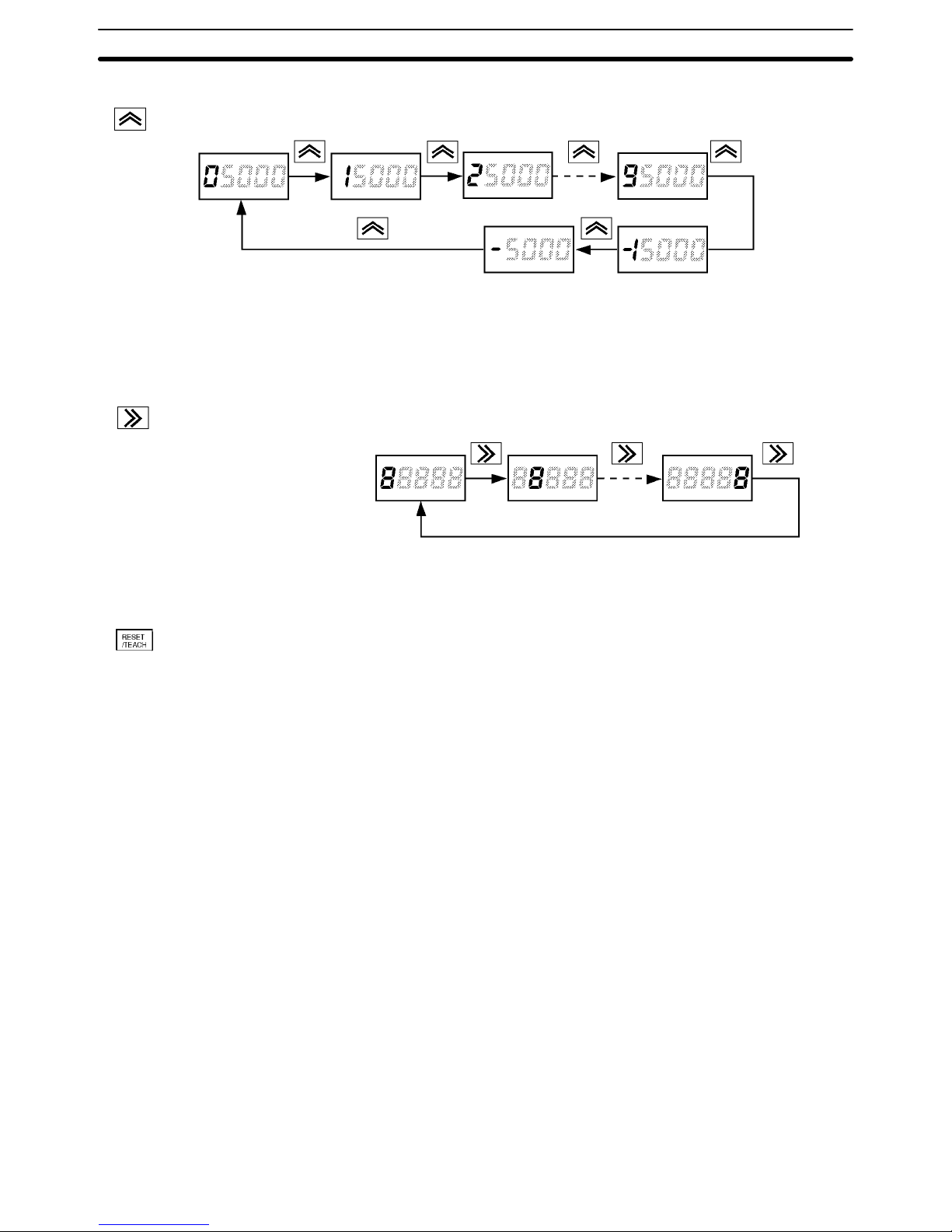
Used to select a parameter to be displayed for setting value change.
Used to increment the current digit in the setting value by one.
The value increases in the following order:
0, 1, 2, 3, 4, 5, 6, 7, 8, 9, (–1), and (–)
Only the leftmost digit will be displayed if the value is set to “–1” or“ –.”
The value will be set to 0 if this key is pressed when “9” or “–” is displayed.
Used to change the parameter displayed in setting mode.
Used to scroll the digit to the right of the presently displayed digit.
Used to reset the maximum value, minimum value, or counting value in RUN
mode.
Used to select the teaching function. Refer to 6-1 Teaching Function for details.
Up Key
Shift Key
RESET/TEACH Key
Front of the Meter
Section 1-2
Page 18
7
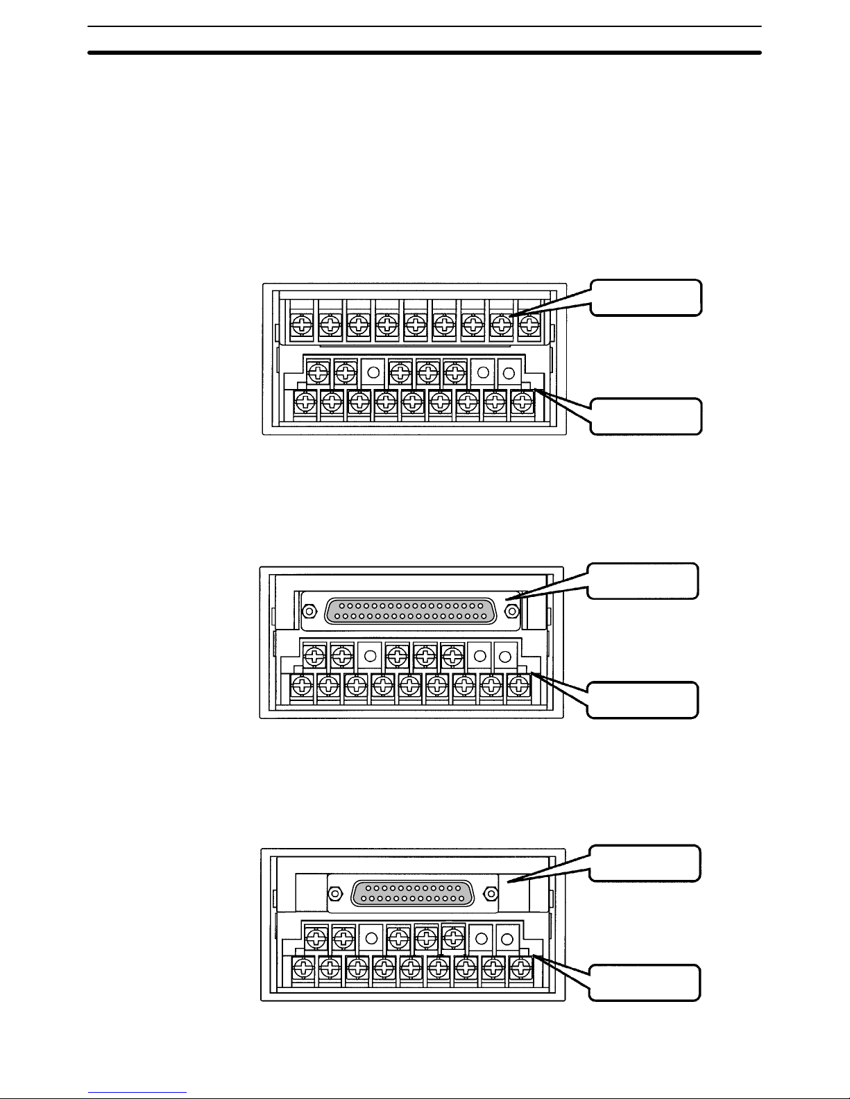
1-3 Rear of the Meter
Terminal arrangement varies depending on the selected Output Board.
For wiring, refer to Section 2 Setup.
K3NR with Relay Output Board, K31-C1, -C2, -C5
K3NR with Transistor Output Board, K31-T1, -T2
K3NR with Linear Output Board, K31-L1, -L2, -L3, -L4, -L5, -L6, -L7, -L8, -L9, -L10
K3NR with RS-485 Output Board, K31-FLK2, -FLK5
Output Board
Input Board
K3NR with BCD Output Board, K31-B2, -B4
Output Board
Input Board
K3NR with RS-232C Output Board, K31-FLK1
Communications
Output Board
Input Board
Rear of the Meter
Section 1-3
Page 19
8
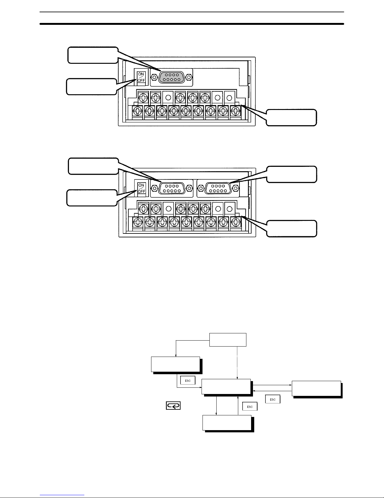
K3NR with RS-422 Output Board, K31-FLK3
Communications
Output Board
Terminator
Input Board
K3NR with RS232C + Transistor Output Board, K31-FLK4
K3NR with RS-422 + Transistor Output Board, K31-FLK6
Communications
Output Board
Terminator
Input Board
Transistor
Output Board
1-4 Modes
The following four modes are available.
• RUN mode for normal operations (see Section 5 Operations in RUN Mode)
• Setting mode for initializing parameter input (see Section 4 Parameter Setting)
• Protect mode for lock-out configuration (see 4-1 Protect Mode)
• Maintenance mode for initialization (see 6-3-2 Initialization)
Refer to the following for the relationship among these modes and selection of
the modes.
RUN mode
Press the Mode and Shift Keys
while turning on the K3NR.
Power on
Press the Escape and up
Keys for 1 second.
Maintenance mode
RUN mode
1 second
Setting mode
Protect mode
RUN Mode K3NR is in RUN when the K3NR is turned ON.
The K3NR in this mode provides an output signal as a result of the comparison of
the measured and setting values.
Modes
Section 1-4
Page 20

9
The basic model in this mode usually displays the process value. The maximum
and minimum values are displayed by pressing the Escape Key. The parameters and setting values are displayed by pressing the Mode Key.
Refer to Section 5 Operations in RUN Mode for RUN mode in detail.
Setting Mode Values are set in the K3NR in this mode by key input or using the teaching func-
tion.
Refer to Section 4 Parameter Setting for value setting by key input and 6-1
Teaching Function for the teaching function in detail.
Protect Mode Use this mode to prohibit some operations in order to lock out the setting values.
Refer to 4-1 Protect Mode for details.
Maintenance Mode The setting values are reset to factory-set values in this mode. Refer to 6-3-2
Initialization for details.
1-5 Communications Function
The communications function of the K3NR makes it possible for the host computer to perform the following operations.
• Confirmation and change of setting values. Communications conditions can-
not be changed.
• Reading and resetting the maximum and minimum values.
• Confirmation of model data.
Use a model with the Communications Board if the communications function is
required.
Refer to the Communications Manual for the communications function in detail.
RS-232C Use the K31-FLK1 or K31-FLK4 Output Board to use the RS-232C interface.
RS-422 Use the K31-FLK3 or K31-FLK6 Output Board to use the RS-422 interface.
RS-485 Use the K31-FLK2 or K31-FLK5 Output Board to use the RS-485 interface.
Communications Function
Section 1-5
Page 21

11
SECTION 2
Setup
This section provides instructions required for mounting and wiring the K3NR.
2-1 Mounting 12. . . . . . . . . . . . . . . . . . . . . . . . . . . . . . . . . . . . . . . . . . . . . . . . . . . . . . . . . . . . . . .
2-2 Input Block 13. . . . . . . . . . . . . . . . . . . . . . . . . . . . . . . . . . . . . . . . . . . . . . . . . . . . . . . . . . . . . .
2-2-1 Terminal Arrangement 13. . . . . . . . . . . . . . . . . . . . . . . . . . . . . . . . . . . . . . . . . . . . . .
2-2-2 Wiring Precautions 14. . . . . . . . . . . . . . . . . . . . . . . . . . . . . . . . . . . . . . . . . . . . . . . . .
2-2-3 Wiring 14. . . . . . . . . . . . . . . . . . . . . . . . . . . . . . . . . . . . . . . . . . . . . . . . . . . . . . . . . .
2-3 Output Board 16. . . . . . . . . . . . . . . . . . . . . . . . . . . . . . . . . . . . . . . . . . . . . . . . . . . . . . . . . . . .
2-3-1 Terminal Arrangement 16. . . . . . . . . . . . . . . . . . . . . . . . . . . . . . . . . . . . . . . . . . . . . .
2-3-2 Relay Output Board 18. . . . . . . . . . . . . . . . . . . . . . . . . . . . . . . . . . . . . . . . . . . . . . . .
2-3-3 Transistor and Combination Output Board 19. . . . . . . . . . . . . . . . . . . . . . . . . . . . . .
2-3-4 Linear Output Board 19. . . . . . . . . . . . . . . . . . . . . . . . . . . . . . . . . . . . . . . . . . . . . . .
2-3-5 BCD Output Board 19. . . . . . . . . . . . . . . . . . . . . . . . . . . . . . . . . . . . . . . . . . . . . . . .
Page 22
12
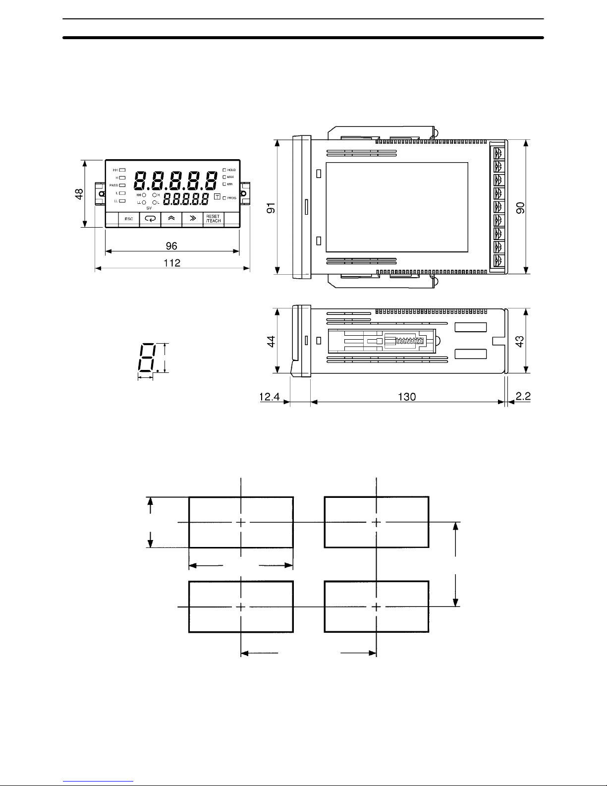
2-1 Mounting
Dimensions All dimensions are in millimeters.
14.2 mm
8.2 mm
PV LED Indicator Size
Panel Cutouts
45
+0.8
–0
92
+0.8
–0
120 min.
75 min.
Recommended panel thickness is 1 to 3.2 mm.
Do not mount more than one Unit closely in the horizontal or vertical direction. Be
sure to keep the distance between adjacent Units.
Mounting Section 2-1
Page 23
13
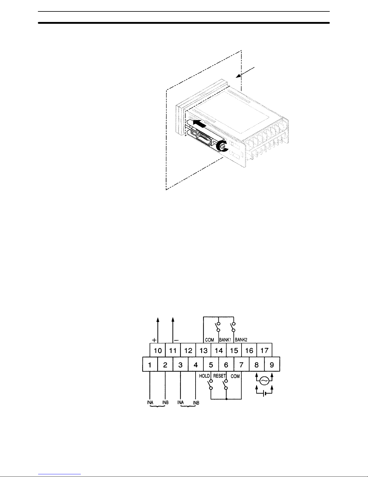
Mounting Method
Panel
1, 2, 3... 1. Insert the K3NR into the mounting hole on the panel.
2. Hook the fixture claws onto the side holes.
3. Mount a fixing metal to the right and left sides as shown above and while
keeping them in balance, alternately tighten each screw until the ratchet becomes idle.
2-2 Input Block
2-2-1 Terminal Arrangement
Sensor power supply
(80 mA max. at 12 VDC)
Open collector
input
Voltage pulse
input
100 to 240 to VAC
12 to 24 VDC
Note Voltage pulse input is available for the K3NR-NBjj-jj.
Input Block
Section 2-2
Page 24
14
2-2-2 Wiring Precautions
• Do not make any mistake in polarity when supply DC power to the K3NR.
• Do not wire power lines alongside the signal lines of the K3NR in order to pre-
vent the K3NR from noise interference.
• Wire the terminal block with crimp terminals.
• Tighten each screw to a torque of 0.78 N S m (8 kgf S cm).
2-2-3 Wiring
Power Supply Apply 100 to 240 VAC or 12 to 24 VDC to terminals 8 and 9.
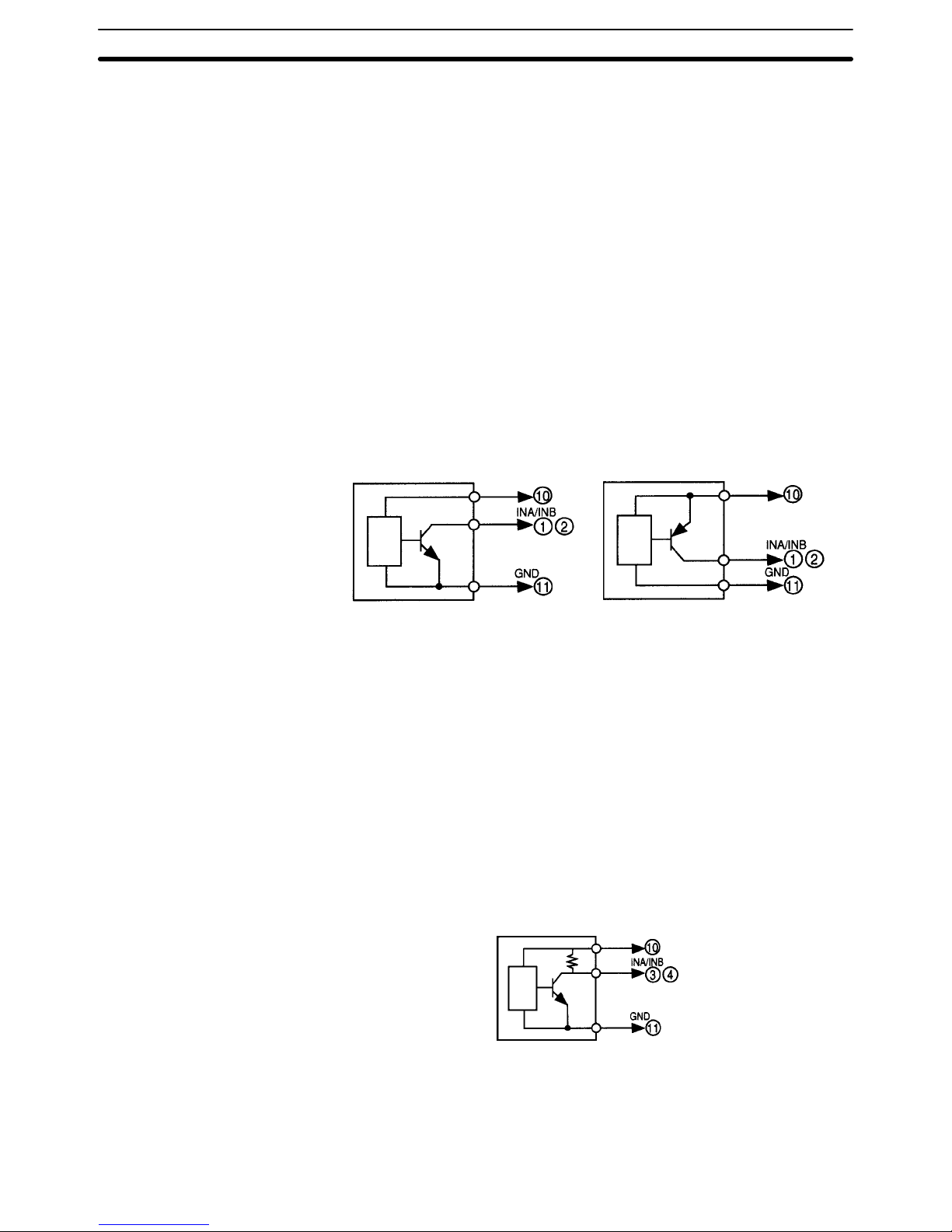
Open Collector Input Connect the pulse output from sensor A to terminal 1.
Connect the pulse output from sensor B to terminal 2.
Terminals 10 and 11 are exclusively used for a power supply with an output of
80 mA at 12 VDC to sensor A or B. If power is supplied to the sensor A or B from a
different power source, do not use terminal 10. Do not connect a sensor with
open collector output to terminal 10.
Refer to the following for sensor connections.
Sensor (with NPN output)
Sensor (with PNP output)
+12 V
+12 V
• Residual voltage with sensor turned on: 3 V max.
• Current leakage with sensor turned off: 1.5 mA max.
• Switching load current: 20 mA or greater. Must be able to dependably switch
a load current of 5 mA max.
Photoelectric sensors, proximity sensors, rotary encoders, and relays can be
connected as sensors to the K3NR.
Voltage Pulse Input Connect the pulse output of sensor A to terminal 3.
Connect the pulse output of sensor B to terminal 4.
Terminals 10 and 11 are exclusively used for a power supply with an output of
80 mA at 12 VDC to sensor A or B. If power is supplied to the sensor A or B from a
different power source, do not use terminal 10. Do not connect a sensor with
voltage pulse output to terminal 10.
Refer to the following for sensor connections.
Sensor
+12 V
H level (sensor output ON): 4.5 to 30 VDC
L level (sensor output OFF): –30 to 2 VDC
Auxiliary Power Supply Terminals 10 and 11 are exclusively used for power supply to sensors with an
output of 80 mA at 12 VDC ± 10%.
Input Block
Section 2-2
Page 25
15
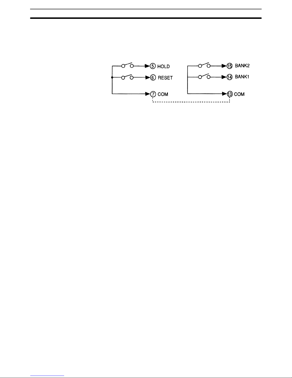
External Signal Input HOLD Input
RESET Input
BANK Input
Connect external signal inputs to terminals 5 through 7 and 13 through 15. Terminals 7 and 13 are connected to each other internally.
Short-circuited together internally.
Connect HOLD input to terminal 5.
Connect RESET input to terminal 6.
Connect BANK inputs to terminals 14 and 15 for BANK1 and BANK2.
If open collector input is used as external signal input, the transistor must satisfy
the following conditions.
• Residual voltage with transistor turned on: 3 V max.
• Current leakage with transistor turned off: 1.5 mA max.
• Switching load current: 20 mA or greater.
Approximately 5 V is imposed between COM and terminals 5 to 7 with a current
flow of approximately 18 mA (a nominal value) at the time of external input shortcircuiting.
Input Block
Section 2-2
Page 26
16
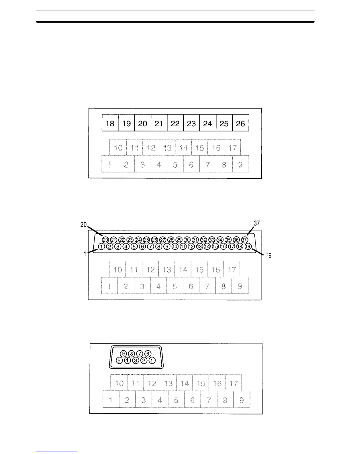
2-3 Output Board
2-3-1 Terminal Arrangement
K3NR with Relay Output Board, K31-C1, -C2. -C5
K3NR with Transistor Output Board, K31-T1, -T2
K3NR with Linear Output Board, K31-L1, -L2, -L3, -L4, -L5, -L6, -L7, -L8, -L9, -L10
K3NR with RS-485 Output Board, K31-FLK2, -FLK5
K3NR with BCD Output Board, K31-B2, -B4
K3NR with RS232C + Transistor Output Board, K31-FLK4
Output Board
Section 2-3
Page 27
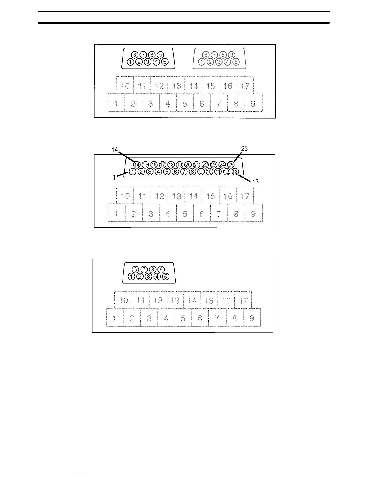
17
K3NR with RS-422 + Transistor Output Board, K31-FLK6
K3NR with RS-232C Output Board, K31-FLK1
K3NR with RS-422 Output Board, K31-FLK3
Output Board
Section 2-3
Page 28
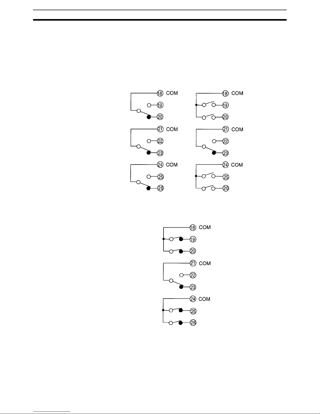
18
2-3-2 Relay Output Board
The following figures show the connections for relay output.
K3NR with 3 Relay
Output Boards,
K31-C1
K3NR with 5 Relay
Output Boards,
K31-C2
H
comparative
output
HH comparative
output
H comparative
output
PASS
output
PASS
output
L
comparative
output
L comparative
output
LL comparative
output
HH comparative
output
PASS
output
LL comparative
output
H comparative
output
L comparative
output
K3NR with 5 Relay
Output Boards,
K31-C5
The following contact output conditions are required.
5 A (resistive load) at 250 VAC
1.5 A (inductive load) at 250 VAC
5 A (resistive load) at 30 VDC
1.5 A (inductive load) at 30 VDC
Output Board
Section 2-3
Page 29
19
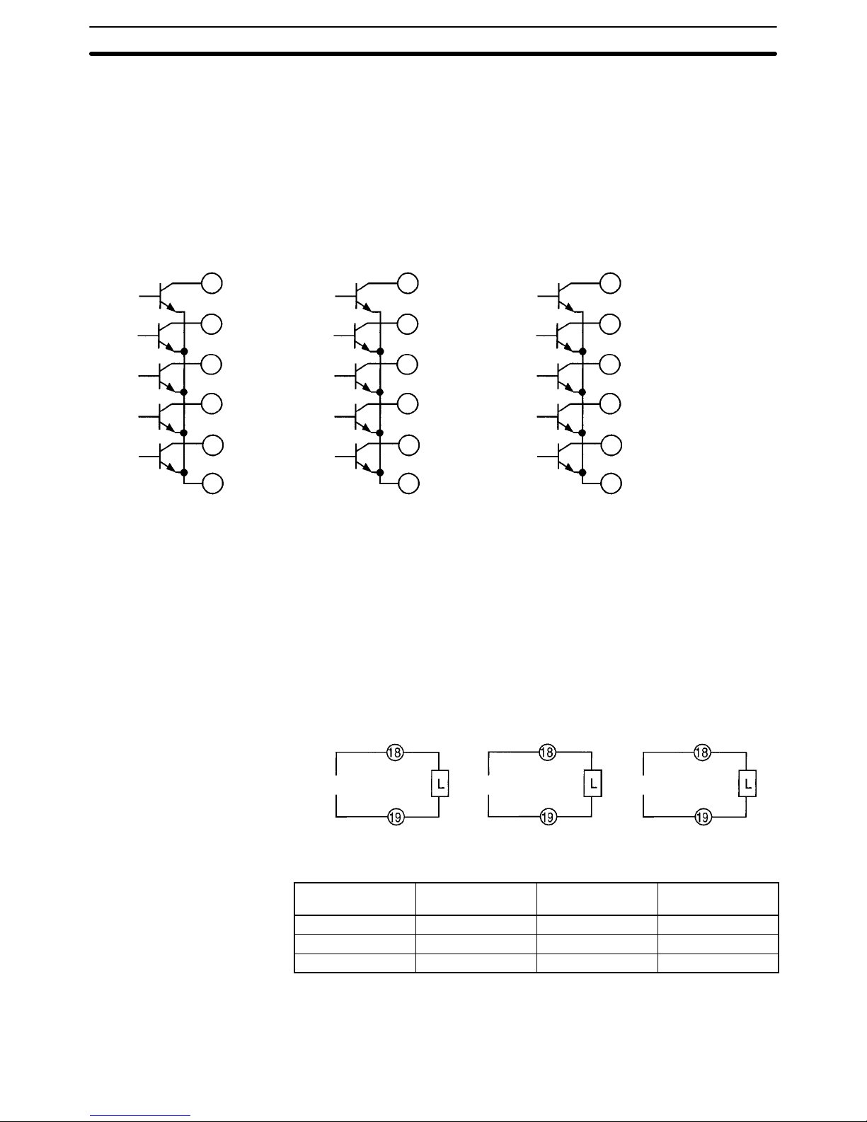
2-3-3 Transistor and Combination Output Board
HH comparative
output
H comparative
output
PASS output
L comparative
output
LL comparative
output
HH comparative
output
H comparative
output
PASS output
L comparative
output
LL comparative
output
HH comparative
output
H comparative
output
PASS output
L comparative
output
LL comparative
output
K3NR with Transistor Output
Board, K31-T1 or K31-T2
K3NR with Linear Output Board,
K31-L4, -L5, -L6, -L9, -L10
K3NR with RS-485 + 5 Relay
Output Boards, K31-FLK5
K3NR with BCD Output
Board, K31-B2 or K31-B4
K3NR with RS232C + 5
Transistor Output Boards,
K31-FLK4
K3NR with RS-422 + 5
Transistor Output Boards,
K31-FLK6
1
2
3
4
5
6
21
22
23
24
25
26
COM
COM
COM
32
33
34
35
36
37
The following transistor output conditions are required.
Maximum rated voltage: 24 VDC
Load current: 50 mA
Current leakage with transistor turned off: 100 µA
2-3-4 Linear Output Board
The following figures show connections for linear output.
K3NR with Linear
Output Board,
K31-L1 or K31-L4
K3NR with Linear
Output Board,
K31-L2 or K31-L5
4 to 20 mA 1 to 5 V
+
–
+
–
K3NR with Linear
Output Board,
K31-L3 or K31-L6
1 mV/10 digit
+
–
The following linear output conditions are required.
Linear output Permissible load
resistance
Resolution Output error
4 to 20 mA 600 Ω max. 4096 ±0.5% FS
1 to 5 V 500 Ω min. 4096 ±0.5% FS
1 mV/10 digit 1 kΩ min. 4096 ±1.5% FS
2-3-5 BCD Output Board
Refer to Section 7 BCD Output for the terminal arrangement and interface.
Output Board
Section 2-3
Page 30

21
SECTION 3
Operating Modes
This section provides information on the basic functions of each operating mode.
3-1 Rotational/Circumferential Speed: f1 22. . . . . . . . . . . . . . . . . . . . . . . . . . . . . . . . . . . . . . . . .
3-2 Absolute Ratio: f2 25. . . . . . . . . . . . . . . . . . . . . . . . . . . . . . . . . . . . . . . . . . . . . . . . . . . . . . . .
3-3 Error Ratio: f3 28. . . . . . . . . . . . . . . . . . . . . . . . . . . . . . . . . . . . . . . . . . . . . . . . . . . . . . . . . . .
3-4 Rotational Difference: f4 31. . . . . . . . . . . . . . . . . . . . . . . . . . . . . . . . . . . . . . . . . . . . . . . . . . .
3-5 Flow Rate Ratio: f5 34. . . . . . . . . . . . . . . . . . . . . . . . . . . . . . . . . . . . . . . . . . . . . . . . . . . . . . .
3-6 Passing Time: f6 37. . . . . . . . . . . . . . . . . . . . . . . . . . . . . . . . . . . . . . . . . . . . . . . . . . . . . . . . .
3-7 Pulse Counting: f7 40. . . . . . . . . . . . . . . . . . . . . . . . . . . . . . . . . . . . . . . . . . . . . . . . . . . . . . . .
Page 31

22
3-1 Rotational/Circumferential Speed: f1
Application example
Measures the rotations of the roll.
Basic Operation
Multiplies the input frequency (Hz) of INA by 60 and displays the result in rpm.
When the appropriate prescale value is selected, the rotational speed of the object is displayed. Obtain display value D as follows:
D = f
A
x 60 x α
fA: Input frequency of INA (Hz)
α: Prescale value
INB input will be ignored.
Item Unit of display Prescale value
Rotations rpm 1/N
rps 1/60N
Frequency of input
pulse
Hz 1/60
kHz 1/60000
Rotational speed mm/s
1000πd/60N
cm/s
100πd/60N
m/s
πd/60N
m/min
πd/N
km/h
0.06πd/N
Where,
N: Number of pulses per rotation
πD: Length (m) of one rotation
Example:
Displaying rotations (rpm) on condition that there are two pulses per revolution.
Prescaling value (α) = 1/2 = 0.5 = 5.0000 x 10
–1
Prescale value = X x 10Y (X: mantissa, Y: exponent)
X (mantissa) of input A = 5.0000
Y (exponent) of input A = –1
Refer to 4-2 Setting Mode.
FUNCTION
SETTING
REFERENCE
Rotational/Circumferential Speed: f1
Section 3-1
Page 32

23
Hold Measured Value When the HOLD input is turned ON, measurement stops and the input mea-
sured just before the HOLD input turned ON is held. While the HOLD input is
ON, the K3NR holds display output, comparative output, and BCD output.
When the comparative output from the Output Board is connected to the
HOLD input terminal, the value measured immediately after the occurrence
of an error can be obtained.
Performance Characteristics
Accuracy of measurement
±0.006% rdg ± 1 digit (ambient temperature: 23°C ± 5°C)
Measurement range Sensor with transistor output: 0.5 mHz to 50 kHz
Sensor with relay output: 0.5 mHz to 30 Hz
ON/OFF pulse width
Sensor with transistor output: 9 µs min.
Sensor with relay output: 15 ms min.
Response time Output configuration
Relay output Transistor
output
BCD and
transistor output
Linear and
transistor output
Communication
and transistor
output
Comparative output 200 ms max.
BCD output --- --- Refer to page 115. --- ---
Linear output --- --- --- 220 ms max. ---
Rotational/Circumferential Speed: f1
Section 3-1
Page 33

24
Available functions in this mode are indicated as “Yes” in the following table.
Menu Function Displayed
Character
Availability Reference
page
---
Max./Min. value display and reset --- Yes 103
Estimated frequency calculation --- Ye s 129
sUset
Set value bank no. of set values
s.bank
Yes 50
(See note 2)
HH set value
sU*.hh
H set value
sU*. h
L set value
sU*. l
LL set value
sU*.ll
pscl
Select bank no. of prescale value
p.bank
Yes
54
Prescaling value of input A
X (mantissa)
Y (exponent)
ps*.ax
ps*.ay
Yes
Prescaling value of input B
X (mantissa)
Y (exponent)
ps*.bx
ps*.by
No
Decimal point position
decp.*
Yes
setup
Operating mode
func
Yes 58
Input A sensor type
ina
Yes
60
Input B sensor type
inb
No
Auto zero time of input A
X (mantissa)
Y (exponent)
=ro.ax
=ro.ay
Yes
62
Auto zero time of input B
X (mantissa)
Y (exponent)
=ro.bx
=ro.by
No
Display time unit
time
No 65
Communications unit no. (See note 1)
uĆno
Yes
67
Baud rate (See note 1)
bps
Yes
Word length (See note 1)
len
Yes
69
Stop bits (See note 1)
sbit
Yes
Parity bits (See note 1)
prty
Yes
opt
Process time for averaging measured value
aUg
Yes 72
Startup compensation time
stime
Yes 74
Power failure memory
memo
No 76
Hysteresis (See note 1)
hys
Yes 78
Comparative output pattern (See note 1)
cĆout
Yes 80
H linear output range (See note 1)
lset.h
Yes
83
L Linear output range (See note 1)
lset.l
Yes
Remote/Local programming (See note 1)
rĆl
Yes 86
Note 1. The availability of the parameters depends on the type of selected Output
Board.
2. The selected bank number will be displayed where an asterisk (*) appears.
Available Functions
Rotational/Circumferential Speed: f1
Section 3-1
Page 34

25
3-2 Absolute Ratio: f2
Operation example
Measures the
rotation ratio of
the rolls.
Basic Operation
Displays the absolute ratio of the frequencies of INA and INB in percentage. Obtain display value D as follows:
D (%) =
f
B x
β
f
A x
α
x 100
f
A
: Input frequency of INA (Hz)
f
B
: Input frequency of INB (Hz)
α: Prescale value of INA
β: Prescale value of INB
Mode Unit of display Prescale value
Absolute ratio % Na and Nb or
πda/Na and
πdb/Nb
Where,
Na: Number of pulses per revolution from A input
Nb: Number of pulses per revolution from B input
πda: Circumference (m) per revolution for A input
πdb: Circumference (m) per revolution for B input
Example:
Displaying absolute revolution rate using two rotary encoders each with
1,000 output pulses per revolution.
Prescale value of INA (α) = 1/1000 = 0.001 = 1.0000 x 10
–3
Prescale value of INB (β) = 1/1000 = 0.001 = 1.0000 x 10
–3
Prescale value = X x 10Y (X: mantissa, Y: exponent)
X (mantissa) of input A = 1.0000
Y (exponent) of input A = –3
X (mantissa) of input B = 1.0000
Y (exponent) of input B = –3
Refer to 4-2 Setting Mode.
FUNCTION
SETTING
REFERENCE
Absolute Ratio: f2
Section 3-2
Page 35

26
Hold Measured Value When the HOLD input is turned ON, measurement stops and the input mea-
sured just before the HOLD input turned ON is held. While the HOLD input is
ON, the K3NR holds display output, comparative output, and BCD output.
When the comparative output from the Output Board is connected to the
HOLD input terminal, the value measured immediately after the occurrence
of an error can be obtained.
Performance Characteristics
Accuracy of measurement
±0.02% rdg ± 1 digit (ambient temperature: 23°C ± 5°C)
Measurement range Sensor with transistor output: 0.5 mHz to 50 kHz
Sensor with relay output: 0.5 mHz to 30 Hz
ON/OFF pulse width
Sensor with transistor output: 9 µs min.
Sensor with relay output: 15 ms min.
Response time Output configuration
Relay output Transistor
output
BCD and
transistor output
Linear and
transistor output
Communication
and transistor
output
Comparative output 200 ms max.
BCD output --- --- Refer to page 115. --- ---
Linear output --- --- --- 220 ms max. ---
Absolute Ratio: f2
Section 3-2
Page 36

27
Available functions in this mode are indicated as “Yes” in the following table.
Menu Function Displayed
Character
Availability Reference
page
---
Max./Min. value display and reset --- Yes 103
Estimated frequency calculation --- Ye s 129
sUset
(See note 2)
Set value bank no. of set values
s.bank
Yes 50
(See note 2)
HH set value
sU*.hh
H set value
sU*. h
L set value
sU*. l
LL set value
sU*.ll
pscl
Select bank no. of prescale value
p.bank
Yes
54
Prescaling value of input A
X (mantissa)
Y (exponent)
ps*.ax
ps*.ay
Yes
Prescaling value of input B
X (mantissa)
Y (exponent)
ps*.bx
ps*.by
Yes
Decimal point position
decp.*
Yes
setup
Operating mode
func
Yes 58
Input A sensor type
ina
Yes
60
Input B sensor type
inb
Yes
Auto zero timer of input A
X (mantissa)
Y (exponent)
=ro.ax
=ro.ay
Yes
62
Auto zero timer of input B
X (mantissa)
Y (exponent)
=ro.bx
=ro.by
Yes
Display time unit
time
No 65
Communications unit no. (See note 1)
uĆno
Yes
67
Baud rate (See note 1)
bps
Yes
Word length (See note 1)
len
Yes
69
Stop bits (See note 1)
sbit
Yes
Parity bits (See note 1)
prty
Yes
opt
Process time for averaging measured value
aUg
Yes 72
Startup compensation time
stime
Yes 74
Power failure memory
memo
No 76
Hysteresis (See note 1)
hys
Yes 78
Comparative output pattern (See note 1)
cĆout
Yes 80
H linear output range (See note 1)
lset.h
Yes
83
L Linear output range (See note 1)
lset.l
Yes
Remote/Local programming (See note 1)
rĆl
Yes 86
Note 1. The availability of the parameters depends on the type of selected Output
Board.
2. The selected bank number will be displayed where an asterisk (*) appears.
Available Functions
Absolute Ratio: f2
Section 3-2
Page 37

28
3-3 Error Ratio: f3
Application example
Measures the speed
of the conveyor belts
and the error ratio in
the rotation of the
conveyor belts.
Basic Operation
Displays the error ratio of the frequency of INA and INB in percentage. Obtain
display value D as follows:
D (%) =
x 100
f
B
x β – fA x α
f
A
x α
f
A
: Input frequency of INA (Hz)
f
B
: Input frequency of INB (Hz)
α: Prescale value of INA
β: Prescale value of INB
Mode Unit of display Prescale value
Error ratio % Na and Nb or
πda/Na and
πdb/Nb
Where,
Na: Number of pulses per revolution from A input
Nb: Number of pulses per revolution from B input
πda: Circumference (m) per revolution for A input
πdb: Circumference (m) per revolution for B input
Example:
Displaying error ratio of two conveyor speeds (m/min) using two rotary encoders each with 100 output pulses per revolution and a circumference of
0.125 m.
Prescale value of INA (α) = 0.125/100 = 0.00125 = 1.2500 x 10
–3
Prescale value of INB (β) = 0.125/100 = 0.00125 = 1.2500 x 10
–3
Prescale value = X x 10Y (X: mantissa, Y: exponent)
X (mantissa) of input A = 1.2500
Y (exponent) of input A = –3
X (mantissa) of input B = 1.2500
Y (exponent) of input B = –3
Refer to 4-2 Setting Mode.
FUNCTION
SETTING
REFERENCE
Error Ratio: f3
Section 3-3
Page 38

29
Hold Measured Value When the HOLD input is turned ON, measurement stops and the input mea-
sured just before the HOLD input turned ON is held. While the HOLD input is
ON, the K3NR holds display output, comparative output, and BCD output.
When the comparative output from the Output Board is connected to the
HOLD input terminal, the value measured immediately after the occurrence
of an error can be obtained.
Performance Characteristics
Accuracy of measurement
±0.02% rdg ± 1 digit (ambient temperature: 23°C ± 5°C)
Measurement range Sensor with transistor output: 0.5 mHz to 50 kHz
Sensor with relay output: 0.5 mHz to 30 Hz
ON/OFF pulse width
Sensor with transistor output: 9 µs min.
Sensor with relay output: 15 ms min.
Response time Output configuration
Relay output Transistor
output
BCD and
transistor output
Linear and
transistor output
Communication
and transistor
output
Comparative output 200 ms max.
BCD output --- --- Refer to page 115. --- ---
Linear output --- --- --- 220 ms max. ---
Error Ratio: f3
Section 3-3
Page 39

30
Available functions in this mode are indicated as “Yes” in the following table.
Menu Function Displayed
Character
Availability Reference
page
---
Max./Min. value display and reset --- Yes 103
Estimated frequency calculation --- Ye s 129
sUset
Set value bank no. of set values
s.bank
Yes 50
(See note 2)
HH set value
sU*.hh
H set value
sU*. h
L set value
sU*. l
LL set value
sU*.ll
pscl
Select bank no. of prescale value
p.bank
Yes
54
Prescaling value of input A
X (mantissa)
Y (exponent)
ps*.ax
ps*.ay
Yes
Prescaling value of input B
X (mantissa)
Y (exponent)
ps*.bx
ps*.by
Yes
Decimal point position
decp.*
Yes
setup
Operating mode
func
Yes 58
Input A sensor type
ina
Yes
60
Input B sensor type
inb
Yes
Auto zero time of input A
X (mantissa)
Y (exponent)
=ro.ax
=ro.ay
Yes
62
Auto zero time of input B
X (mantissa)
Y (exponent)
=ro.bx
=ro.by
Yes
Display time unit
time
No 65
Communications unit no. (See note 1)
uĆno
Yes
67
Baud rate (See note 1)
bps
Yes
Word length (See note 1)
len
Yes
69
Stop bits (See note 1)
sbit
Yes
Parity bits (See note 1)
prty
Yes
opt
Process time for averaging measured value
aUg
Yes 72
Startup compensation time
stime
Yes 74
Power failure memory
memo
No 76
Hysteresis (See note 1)
hys
Yes 78
Comparative output pattern (See note 1)
cĆout
Yes 80
H linear output range (See note 1)
lset.h
Yes
83
L Linear output range (See note 1)
lset.l
Yes
Remote/Local programming (See note 1)
rĆl
Yes 86
Note 1. The availability of the parameters depends on the type of selected Output
Board.
2. The selected bank number will be displayed where an asterisk (*) appears.
Available Functions
Error Ratio: f3
Section 3-3
Page 40

31
3-4 Rotational Difference: f4
Application example
Measures the rotational difference of
the conveyor belts.
Basic Operation
Displays the rotational difference of INA and INB. Obtain display value D as follows:
D (rpm) = f
B
x 60 x β – fA x 60 x α
f
A
: Input frequency of INA (Hz)
f
B
: Input frequency of INB (Hz)
α: Prescale value of INA
β: Prescale value of INB
Mode Unit of display Prescale value
Rotational
Difference
rpm INA 1/60Na
INB 1/60Nb
Hz (Input pulse
frequency)
INA 1/60
INB 1/60
mm/sec INA
1000πda/60Na
INB
1000πdb/60Nb
m/sec INA
πda/60Na
INB
πdb/60Nb
m/min INA
πda/Na
INB
πdb/Nb
Where,
Na: Number of pulses per revolution from A input
Nb: Number of pulses per revolution from B input
πda: Circumference (m) per revolution for A input
πdb: Circumference (m) per revolution for B input
Example:
Displaying error in frequency (Hz) using two rotary encoders each with 100
output pulses per revolution.
Prescale value of INA (α) = 1/60 = 0.01666... 8 1.6666 x 10
–2
Prescale value of INB (β) = 1/60 = 0.01666... 8 1.6666 x 10
–2
Prescale value = X x 10Y (X: mantissa, Y: exponent)
X (mantissa) of input A = 1.6666
Y (exponent) of input A = –2
X (mantissa) of input B = 1.6666
Y (exponent) of input B = –2
FUNCTION
SETTING
Rotational Difference: f4
Section 3-4
Page 41

32
Refer to 4-2 Setting Mode.
Hold Measured Value When the HOLD input is turned ON, measurement stops and the input mea-
sured just before the HOLD input turned ON is held. While the HOLD input is
ON, the K3NR holds display output, comparative output, and BCD output.
When the comparative output from the Output Board is connected to the
HOLD input terminal, the value measured immediately after the occurrence
of an error can be obtained.
Performance Characteristics
Accuracy of measurement
±0.02% rdg ± 1 digit (ambient temperature: 23°C ± 5°C)
Measurement range Sensor with transistor output: 0.5 mHz to 50 kHz
Sensor with relay output: 0.5 mHz to 30 Hz
ON/OFF pulse width
Sensor with transistor output: 9 µs min.
Sensor with relay output: 15 ms min.
Response time Output configuration
Relay output Transistor
output
BCD and
transistor output
Linear and
transistor output
Communication
and transistor
output
Comparative output 200 ms max.
BCD output --- --- Refer to page 115. --- ---
Linear output --- --- --- 220 ms max. ---
REFERENCE
Rotational Difference: f4
Section 3-4
Page 42

33
Available functions in this mode are indicated as “Yes” in the following table.
Menu Function Displayed
Character
Availability Reference
page
---
Max./Min. value display and reset --- Yes 103
Estimated frequency calculation --- Ye s 129
sUset
Set value bank no. of set values
s.bank
Yes 50
(See note 2)
HH set value
sU*.hh
H set value
sU*. h
L set value
sU*. l
LL set value
sU*.ll
pscl
Select bank no. of prescale value
p.bank
Yes
54
Prescaling value of input A
X (mantissa)
Y (exponent)
ps*.ax
ps*.ay
Yes
Prescaling value of input B
X (mantissa)
Y (exponent)
ps*.bx
ps*.by
Yes
Decimal point position
decp.*
Yes
setup
Operating mode
func
Yes 58
Input A sensor type
ina
Yes
60
Input B sensor type
inb
Yes
Auto zero time of input A
X (mantissa)
Y (exponent)
=ro.ax
=ro.ay
Yes
62
Auto zero time of input B
X (mantissa)
Y (exponent)
=ro.bx
=ro.by
Yes
Display time unit
time
No 65
Communications unit no. (See note 1)
uĆno
Yes
67
Baud rate (See note 1)
bps
Yes
Word length (See note 1)
len
Yes
69
Stop bits (See note 1)
sbit
Yes
Parity bits (See note 1)
prty
Yes
opt
Process time for averaging measured value
aUg
Yes 72
Startup compensation time
stime
Yes 74
Power failure memory
memo
No 76
Hysteresis (See note 1)
hys
Yes 78
Comparative output pattern (See note 1)
cĆout
Yes 80
H linear output range (See note 1)
lset.h
Yes
83
L Linear output range (See note 1)
lset.l
Yes
Remote/Local programming (See note 1)
rĆl
Yes 86
Note 1. The availability of the parameters depends on the type of selected Output
Board.
2. The selected bank number will be displayed where an asterisk (*) appears.
Available Functions
Rotational Difference: f4
Section 3-4
Page 43

34
3-5 Flow Rate Ratio: f5
Application example
A
B
Measures the flow rate
ratio of the mixture of A
and B.
Basic Operation
From the frequency of INA and INB, displays the flow rate ratio of INB in percentage. Obtain display value D as follows:
D (%) =
fB x β
x 100
fA x α + fB x β
fA: Input frequency of INA (Hz)
f
B
: Input frequency of INB (Hz)
α: Prescale value of INA
β: Prescale value of INB
Mode Unit of display Prescale value
Flow rate ratio % INA Na
INB Nb
Where,
Na: Number of pulses for specific quantity of A input
Nb: Number of pulses for specific quantity of B input
Example:
Displaying mixed liquid concentration calculated from the flow rate ratio of
two flow sensors each with a capacity of 10 ȏ/400 rpm.
Prescale value of INA (α) = 10/400 = 0.025 = 2.5000 x 10
–2
Prescale value of INB (β) = 10/400 = 0.025 = 2.5000 x 10
–2
Prescale value = X x 10Y (X: mantissa, Y: exponent)
X (mantissa) of input A = 2.5000
Y (exponent) of input A = –2
X (mantissa) of input B = 2.5000
Y (exponent) of input B = –2
Refer to 4-2 Setting Mode.
FUNCTION
SETTING
REFERENCE
Flow Rate Ratio: f5
Section 3-5
Page 44

35
Hold Measured Value When the HOLD input is turned ON, measurement stops and the input mea-
sured just before the HOLD input turned ON is held. While the HOLD input is
ON, the K3NR holds display output, comparative output, and BCD output.
When the comparative output from the Output Board is connected to the
HOLD input terminal, the value measured immediately after the occurrence
of an error can be obtained.
Performance Characteristics
Accuracy of measurement
±0.02% rdg ± 1 digit (ambient temperature: 23°C ± 5°C)
Measurement range Sensor with transistor output: 0.5 mHz to 50 kHz
Sensor with relay output: 0.5 mHz to 30 Hz
ON/OFF pulse width
Sensor with transistor output: 9 µs min.
Sensor with relay output: 15 ms min.
Response time Output configuration
Relay output Transistor
output
BCD and
transistor output
Linear and
transistor output
Communication
and transistor
output
Comparative output 200 ms max.
BCD output --- --- Refer to page 115. --- ---
Linear output --- --- --- 220 ms max. ---
Flow Rate Ratio: f5
Section 3-5
Page 45

36
Available functions in this mode are indicated as “Yes” in the following table.
Menu Function Displayed
Character
Availability Reference
page
---
Max./Min. value display and reset --- Yes 103
Estimated frequency calculation --- Ye s 129
sUset
Set value bank no. of set values
s.bank
Yes 50
(See note 2)
HH set value
sU*.hh
H set value
sU*. h
L set value
sU*. l
LL set value
sU*.ll
pscl
Select bank no. of prescale value
p.bank
Yes
54
Prescaling value of input A
X (mantissa)
Y (exponent)
ps*.ax
ps*.ay
Yes
Prescaling value of input B
X (mantissa)
Y (exponent)
ps*.bx
ps*.by
Yes
Decimal point position
decp.*
Yes
setup
Operating mode
func
Yes 58
Input A sensor type
ina
Yes
60
Input B sensor type
inb
No
Auto zero time of input A
X (mantissa)
Y (exponent)
=ro.ax
=ro.ay
Yes
62
Auto zero time of input B
X (mantissa)
Y (exponent)
=ro.bx
=ro.by
Yes
Display time unit
time
No 65
Communications unit no. (See note 1)
uĆno
Yes
67
Baud rate (See note 1)
bps
Yes
Word length (See note 1)
len
Yes
69
Stop bits (See note 1)
sbit
Yes
Parity bits (See note 1)
prty
Yes
opt
Process time for averaging measured value
aUg
Yes 72
Startup compensation time
stime
Yes 74
Power failure memory
memo
No 76
Hysteresis (See note 1)
hys
Yes 78
Comparative output pattern (See note 1)
cĆout
Yes 80
H linear output range (See note 1)
lset.h
Yes
83
L Linear output range (See note 1)
lset.l
Yes
Remote/Local programming (See note 1)
rĆl
Yes 86
Note 1. The availability of the parameters depends on the type of selected Output
Board.
2. The selected bank number will be displayed where an asterisk (*) appears.
Available Functions
Flow Rate Ratio: f5
Section 3-5
Page 46

37
3-6 Passing Time: f6
Application example
Measures the passing time for a conveyor line.
Distance
Basic Operation
Measures and displays the input pulse frequency of INA in units of seconds.
By selecting an appropriate prescale value, object passing time D in the range
determined by the prescale value will be displayed. Obtain display value D as
follows:
D (sec) = 1/f
A
x α
f
A
: INA input frequency (Hz)
α: prescale value of INA
Rotational speed = Input frequency (f) x (1/No. of pulses (N) per 1 cycle)
Circumferential speed = Circumference of roll (πd) x rotational speed
Passing time = Processing length (L)/Circumferential speed
INB input will be ignored.
Passing time is measured in this mode. Therefore, if the K3NR does not receive
any pulses for a certain period, the K3NR estimates passing time using the estimated frequency calculation function and increases the displayed value.
Mode Unit of display value Prescale value
Passing time sec L/(πd/N)
N = No. of pulses per 1 cycle from input A
πd = Circumferential length (m) per 1 cycle
L = Processing length (m)
Note The K3NR can display the hour, minute, and second. Refer to page 65 for de-
tails.
Example:
Displaying passing time (sec) using a rotary encoder with 100 output pulses
per revolution.
Circumference of rotary encoder = 0.125 m
Process length = 5 m
Prescaling value (α) = 5/(0.125/100) = 4000 = 4.000 x 10
3
Prescale value = X x 10Y (X: mantissa, Y: exponent)
X (mantissa) of input A = 4.000
Y (exponent) of input A = 3
Refer to 4-2 Setting Mode.
FUNCTION
SETTING
REFERENCE
Passing Time: f6
Section 3-6
Page 47

38
Hold Measured Value When the HOLD input is turned ON, measurement stops and the input mea-
sured just before the HOLD input turned ON is held. While the HOLD input is
ON, the K3NR holds display output, comparative output, and BCD output.
When the comparative output from the Output Board is connected to the
HOLD input terminal, the value measured immediately after the occurrence
of an error can be obtained.
Performance Characteristics
Accuracy of measurement
±0.006% rdg ± 1 digit (ambient temperature: 23°C ± 5°C)
Measurement range Sensor with transistor output: 0.5 mHz to 50 KHz
Sensor with relay output: 0.5 mHz to 30 Hz
ON/OFF pulse width
Sensor with transistor output: 9 µs min.
Sensor with relay output: 15 ms min.
Response time Output configuration
Relay output Transistor
output
BCD and
transistor output
Linear and
transistor output
Communication
and transistor
output
Comparative output 200 ms max.
BCD output --- --- Refer to page 115. --- ---
Linear output --- --- --- 220 ms max. ---
Passing Time: f6
Section 3-6
Page 48

39
Available functions in this mode are indicated as “Yes” in the following table.
Menu Function Displayed
Character
Availability Reference
page
---
Max./Min. value display and reset --- Yes 103
Estimated frequency calculation --- Ye s 129
sUset
Set value bank no. of set values
s.bank
Yes 50
(See note 2)
HH set value
sU*.hh
H set value
sU*. h
L set value
sU*. l
LL set value
sU*.ll
pscl
Select bank no. of prescale value
p.bank
Yes
54
Prescaling value of input A
X (mantissa)
Y (exponent)
ps*.ax
ps*.ay
Yes
Prescaling value of input B
X (mantissa)
Y (exponent)
ps*.bx
ps*.by
No
Decimal point position
decp.*
Yes
setup
Operating mode
func
Yes 58
Input A sensor type
ina
Yes
60
Input B sensor type
inb
No
Auto zero time of input A
X (mantissa)
Y (exponent)
=ro.ax
=ro.ay
Yes
62
Auto zero time of input B
X (mantissa)
Y (exponent)
=ro.bx
=ro.by
No
Display time unit
time
No 65
Communications unit no. (See note 1)
uĆno
Yes
67
Baud rate (See note 1)
bps
Yes
Word length (See note 1)
len
Yes
69
Stop bits (See note 1)
sbit
Yes
Parity bits (See note 1)
prty
Yes
opt
Process time for averaging measured value
aUg
Yes 72
Startup compensation time
stime
Yes 74
Power failure memory
memo
No 76
Hysteresis (See note 1)
hys
Yes 78
Comparative output pattern (See note 1)
cĆout
Yes 80
H linear output range (See note 1)
lset.h
Yes
83
L Linear output range (See note 1)
lset.l
Yes
Remote/Local programming (See note 1)
rĆl
Yes 86
Note 1. The availability of the parameters depends on the type of selected Output
Board.
2. The selected bank number will be displayed where an asterisk (*) appears.
Available Functions
Passing Time: f6
Section 3-6
Page 49

40
3-7 Pulse Counting: f7
Application example
Counts the number of objects.
Basic Operation
Counts the number of pulses of INA and displays the result. Obtain display value
D as follows:
D (pulse count) = C x α
C: Pulse count of INA
α: Prescale value
Hold Displayed Value
By turning the HOLD input ON, the displayed value can be put on HOLD. While
the HOLD input is ON, the pulse counting operation continues, as does comparative output and BCD output. In this case, using the HOLD input is similar to
checking a lap time with a stopwatch.
Interruption of Pulse Counting
With INB input ON, the pulse counting operation is interrupted and the measured value, comparative outputs, and BCD output are on HOLD. Pulse counting will not begin while INB input is ON.
Clearing Accumulated Value
When the RESET input turns ON, the accumulated value is cleared to zero.
Pulse counting will not start while the RESET input is ON.
The accumulated value will be stored or cleared to zero when the K3NR is turned
off, and depends on the setting of the power failure memory (memo) at option
menu.
Note By connecting comparative output with the RESET input terminal, the K3NR can
be used as a single-mode preset counter.
FUNCTION
Pulse Counting: f7
Section 3-7
Page 50

41
Comparative Output
With operating mode 7, comparative output L, LL, H, or HH turns ON when the
measured value exceeds the set value. Refer to following chart for details.
INA input
Process value
RESET input
HH set value
HH comparative output
PASS output
H set value
LL set value
L set value
H comparative output
L comparative output
LL comparative output
Mode Unit of display
value
Prescale value
1 pulse = n counts Count n
n pulses = 1 count Count 1/n
Example:
Counting four pulses as a single unit to be displayed.
Prescaling value (α) = 1/4 = 0.25 = 0.25 x 10
0
Prescale value = X x 10Y (X: mantissa, Y: exponent)
X (mantissa) of input A = 0.25
Y (exponent) of input A = 0
4-2 Setting Mode.
Performance Characteristics
Maximum counting speed Sensor with transistor output: 50 kcps
Sensor with relay output: 30 cps
Counting range 0 to 4 G (with 32-bit counter)
Response time of HOLD or RESET
input
20 ms max.
ON/OFF pulse width
Sensor with transistor output: 9 µs min.
Sensor with relay output: 15 ms min.
SETTING
REFERENCE
Pulse Counting: f7
Section 3-7
Page 51

42
Response time Output configuration
Relay output Transistor
output
BCD and
transistor output
Linear and
transistor output
Communication
and transistor
output
Comparative output 10 ms max. 1 ms max. 20 ms max. 20 ms max. 1 ms max.
BCD output --- --- Refer to page 115. --- ---
Linear output --- --- --- 20 ms max. ---
Maximum pulse counting speed is the maximum speed at which the K3NR
can count INA input pulses accurately. If comparative output is used as control output, the maximum pulse counting speed can be obtained as follows:
Maximum counting speed (cps) = 1/Delay in comparative outputs (sec)
If comparative output is directly connected to RESET input, the maximum
pulse counting speed can be obtained as follows:
Maximum counting speed (cps) = 1/Delay in comparative outputs (sec) + Response time of RESET input (sec)
The response time of the HOLD or RESET input is the time required for the
K3TR to accept HOLD or RESET input after the HOLD or RESET input turns
ON. This is illustrated in the following diagram.
INA
Comparative output
Delay in comparative outputs
HOLD or
RESET input
Acceptance of HOLD or RESET input
Response time of HOLD or RESET input
(20 ms max.)
Maximum Pulse Counting
Speed
Response Time of HOLD or
RESET Input
Pulse Counting: f7
Section 3-7
Page 52

43
Available functions in this mode are indicated as “Yes” in the following table.
Menu Function Displayed
Character
Availability Reference
page
---
Max./Min. value display and reset --- Yes 103
Estimated frequency calculation --- No 129
sUset
Set value bank no. of set values
s.bank
Yes 50
(See note 2)
HH set value
sU*.hh
H set value
sU*. h
L set value
sU*. l
LL set value
sU*.ll
pscl
Select bank no. of prescale value
p.bank
Yes
54
Prescaling value of input A
X (mantissa)
Y (exponent)
ps*.ax
ps*.ay
Yes
Prescaling value of input B
X (mantissa)
Y (exponent)
ps*.bx
ps*.by
No
Decimal point position
decp.*
Yes
setup
Operating mode
func
Yes 58
Input A sensor type
ina
Yes
60
Input B sensor type
inb
Yes
Auto zero time of input A
X (mantissa)
Y (exponent)
=ro.ax
=ro.ay
No
62
Auto zero time of input B
X (mantissa)
Y (exponent)
=ro.bx
=ro.by
No
Display time unit
time
No 65
Communications unit no. (See note 1)
uĆno
Yes
67
Baud rate (See note 1)
bps
Yes
Word length (See note 1)
len
Yes
69
Stop bits (See note 1)
sbit
Yes
Parity bits (See note 1)
prty
Yes
opt
Process time for averaging measured value
aUg
No 72
Startup compensation time
stime
No 74
Power failure memory
memo
Yes 76
Hysteresis (See note 1)
hys
No 78
Comparative output pattern (See note 1)
cĆout
No 80
H linear output range (See note 1)
lset.h
Yes
83
L Linear output range (See note 1)
lset.l
Yes
Remote/Local programming (See note 1)
rĆl
Yes 86
Note 1. The availability of the parameters depends on the type of selected Output
Board.
2. The selected bank number will be displayed where an asterisk (*) appears.
Available Functions
Pulse Counting: f7
Section 3-7
Page 53

45
SECTION 4
Parameter Setting
This section provides instructions for setting the parameters of the K3NR. Be sure to read this section before using the K3NR
Frequency/Rate Meter for the first time.
4-1 Overview 46. . . . . . . . . . . . . . . . . . . . . . . . . . . . . . . . . . . . . . . . . . . . . . . . . . . . . . . . . . . . . . .
4-1-1 Heading Symbols 46. . . . . . . . . . . . . . . . . . . . . . . . . . . . . . . . . . . . . . . . . . . . . . . . . .
4-1-2 Setting Procedures 46. . . . . . . . . . . . . . . . . . . . . . . . . . . . . . . . . . . . . . . . . . . . . . . . .
4-2 Setting Mode 47. . . . . . . . . . . . . . . . . . . . . . . . . . . . . . . . . . . . . . . . . . . . . . . . . . . . . . . . . . . .
4-2-1 Selecting Setting Mode 47. . . . . . . . . . . . . . . . . . . . . . . . . . . . . . . . . . . . . . . . . . . . .
4-2-2 Menu Overview 48. . . . . . . . . . . . . . . . . . . . . . . . . . . . . . . . . . . . . . . . . . . . . . . . . . .
4-2-3 Setting Value Menu (sUset)50. . . . . . . . . . . . . . . . . . . . . . . . . . . . . . . . . . . . . . . . .
Bank No. of Set Value 50. . . . . . . . . . . . . . . . . . . . . . . . . . . . . . . . . . . . . . . . . . . . . . . . . .
HH Set Value 50. . . . . . . . . . . . . . . . . . . . . . . . . . . . . . . . . . . . . . . . . . . . . . . . . . . . . . . . .
H Set Value 50. . . . . . . . . . . . . . . . . . . . . . . . . . . . . . . . . . . . . . . . . . . . . . . . . . . . . . . . . .
L Set Value 50. . . . . . . . . . . . . . . . . . . . . . . . . . . . . . . . . . . . . . . . . . . . . . . . . . . . . . . . . .
LL Set Value 50. . . . . . . . . . . . . . . . . . . . . . . . . . . . . . . . . . . . . . . . . . . . . . . . . . . . . . . . .
4-2-4 Prescaling Menu (pscl)54. . . . . . . . . . . . . . . . . . . . . . . . . . . . . . . . . . . . . . . . . . . .
Bank No. of Prescale 54. . . . . . . . . . . . . . . . . . . . . . . . . . . . . . . . . . . . . . . . . . . . . . . . . . .
Prescaling Value X (Mantissa) of Input A 54. . . . . . . . . . . . . . . . . . . . . . . . . . . . . . . . . .
Prescaling Value Y (Exponent) of Input A 54. . . . . . . . . . . . . . . . . . . . . . . . . . . . . . . . . .
Prescaling Value X (Mantissa) of Input B 54. . . . . . . . . . . . . . . . . . . . . . . . . . . . . . . . . .
Prescaling Value Y (Exponent) of Input B 54. . . . . . . . . . . . . . . . . . . . . . . . . . . . . . . . . .
Decimal Point Position 54. . . . . . . . . . . . . . . . . . . . . . . . . . . . . . . . . . . . . . . . . . . . . . . . .
4-2-5 Setup Menu (setup) 58. . . . . . . . . . . . . . . . . . . . . . . . . . . . . . . . . . . . . . . . . . . . . . . .
Operating Mode 58. . . . . . . . . . . . . . . . . . . . . . . . . . . . . . . . . . . . . . . . . . . . . . . . . . . . . .
Sensor Type 60. . . . . . . . . . . . . . . . . . . . . . . . . . . . . . . . . . . . . . . . . . . . . . . . . . . . . . . . . .
Auto Zero Time of Input A X (Mantissa) 62. . . . . . . . . . . . . . . . . . . . . . . . . . . . . . . . . . .
Auto Zero Time of Input A Y (Exponent) 62. . . . . . . . . . . . . . . . . . . . . . . . . . . . . . . . . .
Auto Zero Time of Input B X (Mantissa) 62. . . . . . . . . . . . . . . . . . . . . . . . . . . . . . . . . . .
Auto Zero Time of Input B Y (Exponent) 62. . . . . . . . . . . . . . . . . . . . . . . . . . . . . . . . . .
Time Unit 65. . . . . . . . . . . . . . . . . . . . . . . . . . . . . . . . . . . . . . . . . . . . . . . . . . . . . . . . . . .
Communications Unit Number 67. . . . . . . . . . . . . . . . . . . . . . . . . . . . . . . . . . . . . . . . . . .
Baud Rate 67. . . . . . . . . . . . . . . . . . . . . . . . . . . . . . . . . . . . . . . . . . . . . . . . . . . . . . . . . . .
Word Length 69. . . . . . . . . . . . . . . . . . . . . . . . . . . . . . . . . . . . . . . . . . . . . . . . . . . . . . . . .
Stop Bits 69. . . . . . . . . . . . . . . . . . . . . . . . . . . . . . . . . . . . . . . . . . . . . . . . . . . . . . . . . . . .
Parity Bits 69. . . . . . . . . . . . . . . . . . . . . . . . . . . . . . . . . . . . . . . . . . . . . . . . . . . . . . . . . . .
4-2-6 Option Menu (opt)72. . . . . . . . . . . . . . . . . . . . . . . . . . . . . . . . . . . . . . . . . . . . . . . .
Process Time for Averaging Measured Value 72. . . . . . . . . . . . . . . . . . . . . . . . . . . . . . . .
Startup Compensation Time 74. . . . . . . . . . . . . . . . . . . . . . . . . . . . . . . . . . . . . . . . . . . . .
Power Failure Memory 76. . . . . . . . . . . . . . . . . . . . . . . . . . . . . . . . . . . . . . . . . . . . . . . . .
Hysteresis 78. . . . . . . . . . . . . . . . . . . . . . . . . . . . . . . . . . . . . . . . . . . . . . . . . . . . . . . . . . .
Comparative Output Pattern 80. . . . . . . . . . . . . . . . . . . . . . . . . . . . . . . . . . . . . . . . . . . . .
Upper Limit (H) of Linear Output Range 83. . . . . . . . . . . . . . . . . . . . . . . . . . . . . . . . . . .
Lower Limit (L) of Linear Output Range 83. . . . . . . . . . . . . . . . . . . . . . . . . . . . . . . . . . .
Remote/Local Programming 86. . . . . . . . . . . . . . . . . . . . . . . . . . . . . . . . . . . . . . . . . . . . .
4-3 Protect Mode 88. . . . . . . . . . . . . . . . . . . . . . . . . . . . . . . . . . . . . . . . . . . . . . . . . . . . . . . . . . . .
4-3-1 Selecting Protect Mode 88. . . . . . . . . . . . . . . . . . . . . . . . . . . . . . . . . . . . . . . . . . . . .
4-3-2 Menu Overview 89. . . . . . . . . . . . . . . . . . . . . . . . . . . . . . . . . . . . . . . . . . . . . . . . . . .
4-3-3 Protect Menu (prot)90. . . . . . . . . . . . . . . . . . . . . . . . . . . . . . . . . . . . . . . . . . . . . . .
All Key Protect 90. . . . . . . . . . . . . . . . . . . . . . . . . . . . . . . . . . . . . . . . . . . . . . . . . . . . . . .
Setting Value Change Prohibit 91. . . . . . . . . . . . . . . . . . . . . . . . . . . . . . . . . . . . . . . . . . .
Counting Value Reset Prohibit 93. . . . . . . . . . . . . . . . . . . . . . . . . . . . . . . . . . . . . . . . . . .
Maximum/Minimum Value Clear Prohibit 95. . . . . . . . . . . . . . . . . . . . . . . . . . . . . . . . . .
Security 97. . . . . . . . . . . . . . . . . . . . . . . . . . . . . . . . . . . . . . . . . . . . . . . . . . . . . . . . . . . . .
Page 54

46
4-1 Overview
4-1-1 Heading Symbols
The following symbols are used for headings in this section.
This symbol precedes an explanation of the parameter’s meaning and function.
This symbol precedes a description of the settings, setting range, and default
value.
This symbol precedes an explanation of procedures for parameters that specify
operations.
This symbol precedes a listing of references and related parameters.
This symbol precedes a listing of the models in which this parameter can be
used.
4-1-2 Setting Procedures
• The K3NR has four modes: RUN mode for normal operations, Setting mode
for initial parameter input, Protect mode for lock-out configuration, and Maintenance mode for initializing set values. The parameters that are accessible on
any individual K3NR will vary depending on the Output Board installed. Refer
to Appendix D Available Parameters.
• The K3NR is in RUN mode when the K3NR is turned on. Parameter settings in
protect or setting mode are described below on the basis that the parameters
are set for the first time.
For the operation in RUN mode, refer to Section 5 Operations in RUN Mode.
• The setting examples are provided on condition that the factory-set values of
the K3NR have not been changed.
FUNCTION
SETTING
PROCEDURE
REFERENCE
MODELS
Overview Section 4-1
Page 55

47
4-2 Setting Mode
4-2-1 Selecting Setting Mode
• The K3NR in RUN mode will go into setting mode if the Mode Key is pressed for
1 s minimum.
• The K3NR in setting mode will go into RUN mode if the Escape Key is pressed.
RUN mode
Press the Mode and Shift Keys
while turning the K3NR on.
Power On
Press the Escape and Up
Keys for 1 second.
Maintenance mode
RUN mode
1 second
Setting mode
Protect mode
• The menu in each mode changes whenever the Mode Key is pressed.
• If the Mode Key is pressed for more than one second while a menu is dis-
played, a parameter will be displayed.
• The parameter changes whenever the Mode Key is pressed.
• If the Shift Key is pressed while a parameter is displayed, the parameter will be
ready to change.
• Press the Up Key to change parameters.
• The digit of a set value is selected with the Shift Key and changed with the Up
Key.
• The PROG indicator is lit while a menu or parameter is displayed.
• The PROG indicator flashes during a set value change.
Note If the operating mode is changed, all the other parameters will be set to default
values except communication setting and set values in protect mode. Therefore,
set the operating mode and sensor type first.
Setting Mode
Section 4-2
Page 56

48
Setting Mode
Section 4-2
4-2-2 Menu Overview
Power On
RUN Mode
Refer to Section 5 Operations in RUN Mode.
Setting Mode
Press the
Mode Key
for 1 second.
Press the Mode and Shift Keys
while turning the K3NR on.
Press the Escape and
Up Keys for 1 second.
Maintenance Mode
Refer to Section 6 Useful Functions.
Protect Mode
Refer to 4-3 Protect Mode.
Setting value menu
Bank no. of set value
HH setting value
H setting value
L setting value
LL setting value
Output Test
Refer to Section 6
Useful Functions.
Prescaling menu
1 to 4
Bank no. of prescale
value
Prescaling value of input A
X (mantissa)
Decimal point position
Press the Mode Key for 1 second.
(see note 1)
Press the Mode Key for 1 second.
Prescaling value of input A
Y (exponent)
Prescaling value of input B
X (mantissa)
Prescaling value of input B
Y (exponent)
Note 1. When making new settings or changing settings of each parameter, press the
Shift Key to shift to the setting state.
The input will be updated automatically if no change is made for five seconds.
2. The K3NR stops measurement in setting mode.
Some menus cannot be set according to the Output Board selected.
If the operating mode is changed, all the other parameters will be set to default
values except communication setting and set values in protect mode. Therefore, set the operating mode and sensor type.
Page 57

49
Setup menu
Press the Mode Key for 1 second.
Operating mode
Input A sensor type
Input B sensor type
Auto zero time of input A
X (mantissa)
Auto zero time of input A
Y (exponent)
Time unit
Communications unit no.
Baud rate
Word length
Stop bits
Parity bits
Option menu
Process time for averaging
measured value
Startup compensation time
Power failure
memory
Hysteresis
Comparative output pattern
H linear output
range
L linear output
range
Remote/Local
processing
Auto zero time of input B
X (mantissa)
Auto zero time of input B
Y (exponent)
Press the Mode Key for 1 second.
Setting Mode
Section 4-2
Page 58

50
4-2-3 Setting Value Menu (sUset)
Bank No. of Set Value
HH Set Value
H Set Value
L Set Value
LL Set Value
• There are two basic methods for setting HH, H, L, and LL set values: by enter-
ing during RUN mode via the front-panel buttons, setting in Setting mode, or by
the teaching function.
Setting Setting range Default
Set value bank 1 to 4 1
HH set value
–19,999 to 99999
99,999
H set value
,
99,999
L set value –19999
LL set value –19999
Set the decimal point position in the prescaling menu.
Refer to 6-1 Teaching Function.
• The menu is only available for the K3NR with Comparative Output Board.
s.bank
sU*.hh
sU*.h
sU*.l
sU*.ll
FUNCTION
SETTING
REFERENCE
MODELS
Setting Mode
Section 4-2
Page 59

51
Follow the steps described below to input the following.
Setting value bank = 2
HH setting value = “8000”
H setting value = “6000”
L setting value = “4000”
LL setting value = “2000”
Set Value LED Display Model Basic Model
1, 2, 3... 1. Press the Mode Key for more than one second while the sUset setting value
menu is displayed. The s.bank setting value bank setting will be displayed.
Set Value LED Display Model Basic Model
2. Press the Shift Key to display the set value 1 for changing. The PROG indicator will flash.
Set Value LED Display Model Basic Model
3. Press the Up Key to set the value to 2. The input will be validated automatically if no change is made for five seconds. The s.bank setting value bank
setting will be displayed again.
Note Press the Mode Key to enter the set value immediately. The sU2.hh
HH setting value of bank 2 setting will be displayed for setting the next
parameter.
Set Value LED Display Model Basic Model
4. Press the Mode Key to display the sU2.hh HH setting value of bank 2 setting.
Set Value LED Display Model Basic Model
5. Press the Shift Key to display the set value 99999 for changing. The PROG
indicator will flash.
Set Value LED Display Model Basic Model
SETTING
EXAMPLE
Setting Mode
Section 4-2
Page 60

52
6. Press the Up and Shift Keys to set the value to 8000. The input will be vali-
dated automatically if no change is made for five seconds. The sU2.hh HH
setting value of bank 2 setting will be displayed again.
Note Press the Mode Key to enter the set value immediately. The sU2.h H
setting value of bank 2 setting will be displayed for setting the next
parameter.
Set Value LED Display Model Basic Model
7. Press the Mode Key to display the sU2.h H setting value of bank 2 setting.
Set Value LED Display Model Basic Model
8. Press the Shift Key to display the set value 99999 for changing. The PROG
indicator will flash.
Set Value LED Display Model Basic Model
9. Press the Up and Shift Keys to set the value to 6000. The input will be vali-
dated automatically if no change is made for five seconds. The sU2. h H set-
ting value of bank 2 setting will be displayed again.
Note Press the Mode Key to enter the set value immediately. The sU2. l L
setting value of bank 2 setting will be displayed for setting the next
parameter.
Set Value LED Display Model Basic Model
10. Press the Mode Key to display the sU2. l L setting value of bank 2 setting.
Set Value LED Display Model Basic Model
11. Press the Shift Key to display the set value Ć19999 for changing. The PROG
indicator will flash.
Set Value LED Display Model Basic Model
Setting Mode
Section 4-2
Page 61

53
12. Press the Up and Shift Keys to set the value to 4000. The input will be vali-
dated automatically if no change is made for five seconds. The sU2. l L set-
ting value of bank 2 setting will be displayed again.
Note Press the Mode Key to enter the input immediately. The sU2.ll LL
setting value setting will be displayed for setting the next parameter.
Set Value LED Display Model Basic Model
13. Press the Mode Key to display the sU2.ll LL setting value of bank 2 setting.
Set Value LED Display Model Basic Model
14. Press the Mode Key to display the set value Ć19999 for changing. The
PROG indicator will flash.
Set Value LED Display Model Basic Model
15. Press the Up and Shift Keys to set the value to 2000. The input will be vali-
dated automatically if no change is made for five seconds. The sU2.ll LL
setting value setting will be displayed again.
Note Press the Mode Key to enter the set value immediately. The s.bank setting value
bank setting will be displayed for setting the next parameter.
Set Value LED Display Model Basic Model
16. Press the Escape Key to display the sUset setting value menu.
Set Value LED Display Model Basic Model
Set Value LED Display Model Basic Model
Setting Mode
Section 4-2
Page 62

54
4-2-4 Prescaling Menu (pscl)
Bank No. of Prescale
Prescaling Value X (Mantissa) of Input A
Prescaling Value Y (Exponent) of Input A
Prescaling Value X (Mantissa) of Input B
Prescaling Value Y (Exponent) of Input B
Decimal Point Position
To display rotational speeds, circumferential speeds, or other values based on
input pulse calculations, the rotational speed must be multiplied by a factor input
before the input pulses are measured. This factor is called a prescale value.
Display value = Measured data x Prescaling value
Prescaling values can be set within a range between 0.0001 x 10⁻⁹ and 9.9999 x
109.
Example:
Setting prescaling value with the input of two pulses per revolution.
Unit: rpm
Operating Mode: 1
Object to be measured
Proximity
Sensor
Two pulses are output per revolution. Therefore, the prescaling value is calculated: 0.5 x 100 = 5.0 x 10
–1
p.bank = off
ps.ax = 5.0000
ps.ay = 10 Ć1
Note Use prescaling banks 1 through four if more than one prescaling value needs to
be set.
Input type Setting Default
p.bank: Bank no. of prescale
OFF/1 to 4 OFF
ps*.ax: Prescaling value X (mantissa)
of input A
0.0001 to 9.9999 1.0000
ps*.ay: Prescaling value Y (exponent)
of input A
–9 to 9 0
ps*.bx: Prescaling value X (mantissa)
of input B
0.0001 to 9.9999 1.0000
ps*.by: Prescaling value Y (exponent)
of input B
–9 to 9 0
decp.*: Decimal point position
Operating modes 3 and 4:
One of the 1st to 3rd digits
from the right
Other modes:
One of the 1st to 4th digits
from the right
No decimal
point
position
setting
p.bank
ps*.ax
ps*.ay
ps*.bx
ps*.by
decp.*
FUNCTION
SETTING
Setting Mode
Section 4-2
Page 63

55
Refer to 6-1 Teaching Function.
Follow the steps described below to input the following.
Operating mode = F1
Prescaling bank = OFF
Prescaling value X (mantissa) of input A = 0.5000
Prescaling value Y (exponent) of input A = –1
Decimal point = jjjj.j (1st digit from the right)
Set Value LED Display Model Basic Model
1, 2, 3... 1. Press the Mode Key for more than one second while the pscl prescaling
menu is displayed. The p.bank prescaling bank setting will be displayed.
Set Value LED Display Model Basic Model
2. Press the Shift Key to display off for changing. The PROG indicator will
flash.
Set Value LED Display Model Basic Model
3. Press the Up Key to change the prescaling bank setting. The input will be
validated automatically if no change is made for five seconds. The p.bank
prescaling bank setting will be displayed again.
Note Press the Mode Key to enter the set value immediately. The ps.ax
prescaling value X (mantissa) of input A setting will be displayed for
setting the next parameter.
Set Value LED Display Model Basic Model
4. Press the Mode Key to display the ps.ax prescaling value X (mantissa) of
input A setting.
Set Value LED Display Model Basic Model
REFERENCE
SETTING
EXAMPLE
Setting Mode
Section 4-2
Page 64

56
5. Press the Shift Key to display the set value 1.0000 for changing. The PROG
indicator will flash.
Set Value LED Display Model Basic Model
6. Press the Up and Shift Keys to set the value to 0.5000. The input will be validated automatically if no change is made for five seconds. The ps.ax prescaling value X (mantissa) of input A setting will be displayed again.
Note Press the Mode Key to enter the set value immediately. The ps.ax
prescaling value X (mantissa) of input A setting will be displayed for
setting the next parameter.
Set Value LED Display Model Basic Model
7. Press the Mode Key to display the ps.ay prescaling value Y (exponent) of
input A setting.
Set Value LED Display Model Basic Model
8. Press the Shift Key to display the set value 10Ć1 for changing.
Set Value LED Display Model Basic Model
9. Press the Up and Shift Keys to set the value to 10 Ć1. The input will be validated automatically if no change is made for five seconds. The ps.ay prescaling value Y (exponent) of input A setting will be displayed again.
Note a) Press the Mode Key to enter the set value immediately. The decp
decimal point position setting will be displayed again.
b) If the set operating mode is F2 through F5, the ps.bx prescaling
value X (mantissa) of input B setting will be displayed.
Set Value LED Display Model Basic Model
Setting Mode
Section 4-2
Page 65

57
10. Press the Mode Key to display the decp decimal point position setting.
Note If the set operating mode is F2 through F5, the ps.bx prescaling value
X (mantissa) of input B setting will be displayed.
Set Value LED Display Model Basic Model
11. Press the Shift Key to display %%%%% for changing.
Set Value LED Display Model Basic Model
12. Press the Shift Key to set %%%%.%. The input will be validated automatically if
no change is made for five seconds. The decp decimal point position setting
will be displayed again.
Note Press the Mode Key to enter the set value immediately. The p.bank
prescaling bank setting will be displayed for setting the next parameter.
Set Value LED Display Model Basic Model
13. Press the Escape Key to display the pscl prescaling menu.
Set Value LED Display Model Basic Model
Set Value LED Display Model Basic Model
Setting Mode
Section 4-2
Page 66

58
4-2-5 Setup Menu (setup)
Operating Mode
Use this menu to select the operating mode of the K3NR. All parameters will be
set to default values if any change is made in this parameter except to those for
the communications and protect settings.
f1: Displays the number of circumferential or rotational speed of in-
put A.
f2 through f5: Displays the result of the arithmetic operation of two different
revolutions.
f6: Displays the value of passing time calculated from the frequen-
cy or processing length of input A.
f7: Displays the pulse counting of input A.
Setting Default
f1: Rotational/circumferential speed
f2: Absolute ratio
f3: Error ratio
f4: Rotational difference
f5: Flow rate ratio
f6: Passing time
f7: Pulse counting
f1
Refer to Section 3 Operating Modes.
Follow the steps described below to select the f4 rotational difference setting.
Set Value LED Display Model Basic Model
1, 2, 3... 1. Press the Mode Key for more than one second while the setup setup menu
is displayed. The func operating mode setting will appear.
Set Value LED Display Model Basic Model
2. Press the Shift Key to display f1 for changing. The PROG indicator will flash.
Set Value LED Display Model Basic Model
func
FUNCTION
SETTING
REFERENCE
SETTING
EXAMPLE
Setting Mode
Section 4-2
Page 67

59
3. Repeatedly press the Up Key until f4 is displayed. The displayed setting will
be validated automatically if no change is made for five seconds. The func
operating mode setting will be displayed again.
Note Press the Mode Key to enter the displayed setting immediately. The
next parameter will be displayed for setting.
Set Value LED Display Model Basic Model
4. Repeatedly press the Escape Key until the setup setup menu is displayed.
Set Value LED Display Model Basic Model
Setting Mode
Section 4-2
Page 68

60
Sensor Type
• Specifies the type of sensors for input A and input B.
• The sensor type of input B cannot be selected if the operating mode of the
K3NR is set to f1 (rotational/circumferential speed) or f6 (passing time).
• Open Collector Input
Sensor type Normally open Normally closed Default
Transistor input
00 01
00
Relay input
10 11
Normally Open Model: The sensor output is OFF (open) when the sensor is
not sensing an object.
Normally Closed Model: The sensor output is ON (closed) when the sensor is
not sensing an object.
• Voltage Pulse Input
Sensor type Active high (H) Active low (L) Default
Voltage pulse input
10 11 00
Follow the steps described below to set input A to 11 in operating mode f1 (rotational/circumferential speed).
Set Value LED Display Model Basic Model
1, 2, 3... 1. Press the Mode Key for more than one second while the setup setup menu
is displayed. The func operating mode setting will appear.
Set Value LED Display Model Basic Model
2. Press the Mode Key to display ina input A sensor type setting.
Set Value LED Display Model Basic Model
3. Press the Shift Key to display 00 for changing. The PROG indicator will flash.
Set Value LED Display Model Basic Model
ina
inb
FUNCTION
SETTING
SETTING
EXAMPLE
Setting Mode
Section 4-2
Page 69

61
4. Press the Up and Shift Keys to display 11. The displayed value will be validated automatically if no change is made for five seconds. The ina input A
sensor type setting will be displayed again.
Note Press the Mode Key to enter the displayed setting immediately. The
next parameter will be displayed.
Set Value LED Display Model Basic Model
5. Press the Escape Key to display the setup setup menu.
Set Value LED Display Model Basic Model
Setting Mode
Section 4-2
Page 70

62
Auto Zero Time of Input A X (Mantissa)
Auto Zero Time of Input A Y (Exponent)
Auto Zero Time of Input B X (Mantissa)
Auto Zero Time of Input B Y (Exponent)
Calibrates the process value to zero forcibly if no input pulse is received for a
certain period. This period is called auto-zero time.
Refer to the following graph.
Frequency
Auto-zero time
Time
Logically, the input pulse frequency does not drop to zero perfectly due to the
estimated frequency calculation of the K3NR. Therefore, the K3NR has a function to calibrate the frequency to zero forcibly if no input pulse is received for a
certain period.
Automatic zero time is determined by the following formula.
Auto-zero time = X x 10
Y
(s) (X: mantissa, Y: exponent)
Note Auto-zero time must be longer than the value obtained by dividing
one by the minimum frequency input of the K3NR. Auto-zero time
must not be less than 0.1 s.
If the operating mode of the K3NR is set to F7 (pulse counting), this parameter
will not be available.
Input type Setting Default
=ro.ax: Auto zero time of input A X (mantissa)
=ro.ay: Auto zero time of input A Y (exponent)
=ro.bx: Auto zero time of input B X (mantissa)
=ro.by: Auto zero time of input B Y (exponent)
0.0001 to 9.9999
–9 to 09
0.0001 to 9.9999
–9 to 09
9.9999
09
9.9999
09
Note For details, refer to page 129 for the estimated frequency calculation of the
K3NR.
Follow the steps described below to set the value of auto-zero time to one second.
Set Value LED Display Model Basic Model
=ro.ax
=ro.ay
=ro.bx
=ro.ay
FUNCTION
SETTING
REFERENCE
SETTING
EXAMPLE
Setting Mode
Section 4-2
Page 71

63
1, 2, 3... 1. Press the Mode Key for more than one second while the setup setup menu
is displayed. The func operating mode setting will appear.
Set Value LED Display Model Basic Model
2. Repeatedly press the Mode Key until the =ro.ax auto zero time of input A X
(mantissa) setting is displayed.
Set Value LED Display Model Basic Model
3. Press the Shift Key to display the set value 9.9999 for changing. The PROG
indicator will flash.
Set Value LED Display Model Basic Model
4. Press the Up and Shift Keys to set the value to 1.0000. The input will be validated automatically if no change is made for five seconds. The =ro.ax auto
zero time of input A X (mantissa) setting will be displayed again.
Note Press the Mode Key to enter the set value immediately. The auto zero
time of input A Y (exponent) setting will be displayed for setting the
next parameter.
Set Value LED Display Model Basic Model
5. Press the Mode Key to display the =ro.ay auto zero time of input A Y (exponent) setting.
Set Value LED Display Model Basic Model
6. Press the Shift Key to display the set value 10 09 for changing.
Set Value LED Display Model Basic Model
7. Press the Up and Shift Keys to set the value to 10 00. The input will be validated automatically if no change is made for five seconds. The =ro.ay auto
zero time of input A Y (exponent) setting will be displayed again.
Setting Mode
Section 4-2
Page 72

64
Note Press the Mode Key to enter the set value immediately. The auto zero
time of input B X (mantissa) setting will be displayed for setting the
next parameter.
Set Value LED Display Model Basic Model
8. Press the Escape Key to display the setup setup menu.
Set Value LED Display Model Basic Model
Setting Mode
Section 4-2
Page 73

65
Time Unit
The time unit can be selected to display the calculation results of F6 (passing
time).
Unit Display range Default
scal
–19999 to 99,999
scal
sec
Displayed in seconds within a range
between 0 and 99,999 s.
min
Displayed minutes within a range
between 0 and 99,999 min.
h.mm.ss
Displayed in hours, minutes, and
seconds within a range between 0 h,
00 min, 00 s and 9 hrs, 59 min, 59 s.
mm.ss.d
Displayed in minutes and seconds
(1/100 s) within a range between 00
min, 00 s 0 and 59 min, 59 s, 9.
Follow the steps described below to set sec second unit setting.
Set Value LED Display Model Basic Model
1, 2, 3... 1. Press the Mode Key for more than one second while the setup setup menu
is displayed. The func operating mode setting will appear.
Set Value LED Display Model Basic Model
2. Repeatedly press the Mode Key until time time unit setting is displayed.
Set Value LED Display Model Basic Model
3. Press the Shift Key to display scal for changing. The PROG indicator will
flash.
Set Value LED Display Model Basic Model
time
FUNCTION
SETTING
SETTING
EXAMPLE
Setting Mode
Section 4-2
Page 74

66
4. Press the Up Key to display sec. The input will be validated automatically if
no change is made for five seconds. The time time unit setting will be displayed again.
Note Press the Mode Key to enter the set value immediately. The next pa-
rameter will be displayed for setting.
Set Value LED Display Model Basic Model
5. Press the Escape Key to display the setup setup menu.
Set Value LED Display Model Basic Model
Set Value LED Display Model Basic Model
Setting Mode
Section 4-2
Page 75

67
Communications Unit Number
Baud Rate
• Set a communications unit number as an identification number by which the
host computer is connected to the K3NR.
• If more than one K3NR is connected in parallel, make sure that each commu-
nications unit number is unique.
• The baud rate should be set to the baud rate of the host computer.
• Communications Unit Number
Setting range Unit Default
00 to 99 --- 00
• Baud Rate
Setting range Default
1200: 1,200 bps / 2400: 2,400 bps / 4800: 4,800 bps /
9600: 9,600 bps / 19200:19.2 Kbps / 38400: 38.4 Kbps
9600
This setting is available for the K3NR with the Communications Output Board.
Follow the steps described below to set the communications unit number to 15 and the
baud rate to 19,200 bps.
Set Value LED Display Model Basic Model
1, 2, 3... 1. Press the Mode Key for more than one second while the setup setup menu
is displayed. The func operating mode setting will appear.
Set Value LED Display Model Basic Model
2. Repeatedly press the Mode Key until the uĆno communications unit number
setting is displayed.
Set Value LED Display Model Basic Model
uĆno
bps
FUNCTION
SETTING
MODELS
SETTING
EXAMPLE
Setting Mode
Section 4-2
Page 76

68
3. Press the Shift Key to display the prior set value 00 for changing. The PROG
indicator will flash.
Set Value LED Display Model Basic Model
4. Press the Up and Shift Keys to set the value to 15. The input value will be
validated automatically if no change is made for five seconds. The uĆno
communications unit number setting will be displayed again.
Note Press the Mode Key to enter the set value immediately. The next pa-
rameter will be displayed for setting.
Set Value LED Display Model Basic Model
5. Press the Mode Key to display the bps baud rate setting.
Set Value LED Display Model Basic Model
6. Press the Shift Key to display the prior set value 9600 for changing. The
PROG indicator will flash.
Set Value LED Display Model Basic Model
7. Press the Up Key to set the value to 19200. The input will be validated automatically if no change is made for five seconds. The bps baud rate setting
will be displayed again.
Note Press the Mode Key to enter the set value immediately. The next pa-
rameter will be displayed again for setting.
Set Value LED Display Model Basic Model
8. Press the Up Key to enter the set value for setting the next parameter. The
input value will be validated automatically if no change is made for five seconds. The bps baud rate setting will be displayed again.
Set Value LED Display Model Basic Model
Setting Mode
Section 4-2
Page 77

69
Word Length
Stop Bits
Parity Bits
• The communications format used for communicating with the host computer is
set in the setup menu.
• Refer to the Communications Manual for the communications format in detail.
• Word Length
Setting Unit Default
7/8 bit 7
• Stop Bits
Setting Unit Default
1/2 bit 2
• Parity Bit
Setting Default
none: None
eUen: Even
odd: Odd
eUen
This setting is available for the K3NR with the Communications Output Board.
Follow the steps described below to set the following.
Word length: 8 bits
Number of stop bits: 1
Parity bits: none
Set Value LED Display Model Basic Model
1, 2, 3... 1. Press the Mode Key for more than one second while the setup setup menu
is displayed. The func operating mode setting will appear.
Set Value LED Display Model Basic Model
len
sbit
prty
FUNCTION
SETTING
MODELS
SETTING
EXAMPLE
Setting Mode
Section 4-2
Page 78

70
2. Repeatedly press the Mode Key until the len word length setting is displayed.
Set Value LED Display Model Basic Model
3. Press the Shift Key to display the prior set value 7 for changing. The PROG
indicator will flash.
Set Value LED Display Model Basic Model
4. Press the Up Key to set the value to 8. The input value will be validated auto-
matically if no change is made for five seconds. The len word length setting
will be displayed again.
Note Press the Mode Key to enter the set value immediately. The next pa-
rameter will be displayed for setting.
Set Value LED Display Model Basic Model
5. Press the Mode Key to display the sbit stop bit setting.
Set Value LED Display Model Basic Model
6. Press the Shift Key to display the set value 2 for changing.
Set Value LED Display Model Basic Model
7. Press the Up Key to set the value to 1. The input will be validated automatically if no change is made for five seconds. The sbit stop bit setting will be
displayed again.
Note Press the Mode Key to enter the set value immediately. The next pa-
rameter will be displayed for setting.
Set Value LED Display Model Basic Model
8. Press the Mode Key to display the prty parity bit setting.
Set Value LED Display Model Basic Model
Setting Mode
Section 4-2
Page 79

71
9. Press the Shift Key to display eUen for changing.
Set Value LED Display Model Basic Model
10. Press the Up Key to display none. The setting will be validated automatically
if no change is made for five seconds. The prty parity bit setting will be displayed again.
Note Press the Mode Key to enter the setting immediately. The next pa-
rameter will be displayed for setting.
Set Value LED Display Model Basic Model
When no operation is executed for five seconds
Set Value LED Display Model Basic Model
Setting Mode
Section 4-2
Page 80

72
4-2-6 Option Menu (opt)
Process Time for Averaging Measured Value
The K3NR averages its measured value at regular preset intervals. Therefore,
when the K3NR is used to measure the rpm of a machine, for example, the value
indicated by the PV display will be stable without being influenced by the fluctuation of the input pulse intervals or the rotation of the machine. If the input pulse
intervals are larger than the preset regular intervals, the K3NR calculates the
rpm using the input pulse intervals.
Setting Default
fast: Averaged every 60 ms
0.5: Averaged every 500 ms
1: Averaged every 1 s
2: Averaged every 2 s
4: Averaged every 4 s
8: Averaged every 8 s
16: Averaged every 16 s
fast
Input value
Display value
Without average processing
Input value
Display value
After average processing
aUg
FUNCTION
SETTING
REFERENCE
Setting Mode
Section 4-2
Page 81

73
Follow the steps described below to set the process time for averaging measured value
to 4 s.
Set Value LED Display Model Basic Model
1, 2, 3... 1. Press the Mode Key for more than one second while the opt option menu is
displayed. The aUg process time for averaging measured value setting will
appear.
Set Value LED Display Model Basic Model
2. Press the Shift Key to display present set value fast for changing. The
PROG indicator will flash.
Set Value LED Display Model Basic Model
3. Repeatedly press the Up Key until 4 is displayed. The setting will be validated automatically if no change is made for five seconds. The aUg process
time for averaging measured value setting will be displayed again.
Note Press the Mode Key to enter the displayed setting immediately. The
next parameter will be displayed.
Set Value LED Display Model Basic Model
When no operation is executed for five seconds
Set Value LED Display Model Basic Model
SETTING
EXAMPLE
Setting Mode
Section 4-2
Page 82

74
Startup Compensation Time
• The interval between the moment the K3NR is turned and the moment the
K3NR starts measurement operation is set in the option menu.
• The startup compensation time parameter keeps the measurement operation
from sending an unnecessary output corresponding to instantaneous, fluctuating input from the moment the K3NR is turned ON until the end of the preset
period.
Setting range Unit Default
0.0 to 99.9
S 0.0
The K3NR will display “00000” with all outputs turned OFF until the K3NR is in
measurement operation.
L set value
L comparative output
Power ON
Display = 00000
(measurement
interrupted)
Setting time
Display
Time
Follow the steps described below to set the startup compensation time to 2 seconds.
Set Value LED Display Model Basic Model
1, 2, 3... 1. Press the Mode Key for more than one second while the opt option menu is
displayed. The aUg process time for averaging measured value setting will
appear.
Set Value LED Display Model Basic Model
stime
FUNCTION
SETTING
REFERENCE
SETTING
EXAMPLE
Setting Mode
Section 4-2
Page 83

75
2. Press the Mode Key to display the stine startup compensation time setting.
Set Value LED Display Model Basic Model
3. Press the Shift Key to display the prior set value 00.0 for changing. The
PROG indicator will flash.
Set Value LED Display Model Basic Model
4. Press the Up and Shift Keys to set the value to 02.0. The setting will be validated automatically if no change is made for five seconds. The stine startup compensation time setting will be displayed again.
Note Press the Mode Key to enter the set value immediately. The next pa-
rameter will be displayed for setting.
Set Value LED Display Model Basic Model
When no operation is executed for five seconds
Set Value LED Display Model Basic Model
Setting Mode
Section 4-2
Page 84

76
Power Failure Memory
Retains the process value at the time of power failure if the operating mode of the
K3NR is set to F7 (pulse counting).
Setting Default
on: Stored
off: Not Stored
off
Follow the steps described below to set on to enable power failure memory.
Set Value LED Display Model Basic Model
1, 2, 3... 1. Press the Mode Key for more than one second while the opt option menu is
displayed. The aUg average processing setting will appear.
Set Value LED Display Model Basic Model
2. Repeatedly press the Mode Key until the memo power failure memory setting
is displayed.
Set Value LED Display Model Basic Model
3. Press the Shift Key to display the set data off for changing. The PROG indicator will flash.
Set Value LED Display Model Basic Model
4. Press the Up Key to display on. The setting will be validated automatically if
no change is made for five seconds. The memo power failure memory setting
will be displayed again.
Note Press the Mode Key to enter the displayed setting immediately. The
next parameter will be displayed for setting.
Set Value LED Display Model Basic Model
memo
FUNCTION
SETTING
SETTING
EXAMPLE
Setting Mode
Section 4-2
Page 85

77
When no operation is executed for five seconds
Set Value LED Display Model Basic Model
5. Press the Escape Key to display the opt option menu.
Set Value LED Display Model Basic Model
Setting Mode
Section 4-2
Page 86

78
Hysteresis
• The hysteresis can be set in the option menu to prevent “chattering” of the out-
put if the measured value fluctuates in the vicinity of the setting values.
• The hysteresis can be set within a range of 1 and 9999 digits for four consecu-
tive digits beginning with the leftmost digit regardless of the decimal point.
• The value set to 0 is regarded as 1.
• The decimal point position set in the scaling menu becomes valid.
Setting range Unit Default
1 to 9999
--- 1
If the comparative output is a level output, however, the hysteresis will be enabled when the measured value starts to become smaller than the HH, H, LL,
and L setting values.
Measured value
H setting value
L setting value
H comparative output
L comparative output
Hysteresis
Hysteresis
This setting is only available for the K3NR with the Comparative Output Unit.
Follow the steps described below to set the hysteresis to 30.
Set Value LED Display Model Basic Model
1, 2, 3... 1. Press the Mode Key for more than one second while the opt option menu is
displayed. The aUg average processing setting will appear.
Set Value LED Display Model Basic Model
hys
FUNCTION
SETTING
REFERENCE
MODELS
SETTING
EXAMPLE
Setting Mode
Section 4-2
Page 87

79
2. Repeatedly press the Mode Key until the hys hysteresis setting is displayed.
Set Value LED Display Model Basic Model
3. Press the Shift Key to display the prior set value 0001 for changing. The
PROG indicator will flash.
Set Value LED Display Model Basic Model
4. Press the Up and Shift Keys to set the value to 0030. The setting will be validated automatically if no change is made for five seconds. The hys hysteresis setting will be displayed again.
Note Press the Mode Key to enter the set value immediately. The next pa-
rameter will be displayed for setting.
Set Value LED Display Model Basic Model
When no operation is executed for five seconds
Set Value LED Display Model Basic Model
Setting Mode
Section 4-2
Page 88

80
Comparative Output Pattern
• The pattern of HH, H, L, LL, and PASS comparative outputs is set in the option
menu.
• This function is not available when the operating mode is set to “F7.”
Setting Default
nomal: Standard output
=one: Zone output
leUel: Level output
nomal
Standard Output
H or HH Comparative Output:
Turns ON when the measured value is larger than the H or HH setting value.
PASS Output:
Turns ON when LL, L, H, and HH comparative outputs are all OFF.
L or LL Comparative Output:
Turns ON when the measured value is smaller than the L or LL setting value.
HH setting value
H setting value
L setting value
LL setting value
Measured value
HH comparative output
H comparative output
PASS
L comparative output
LL comparative output
cĆout
FUNCTION
SETTING
REFERENCE
Setting Mode
Section 4-2
Page 89

81
Level Output
LL, L, H, or HH Comparative Output:
Turns ON when the measured value exceeds the LL, L, H, or HH setting value.
PASS Output:
Turns ON when the LL, L, H, and HH comparative outputs are all OFF.
HH setting value
H setting value
L setting value
LL setting value
Measured value
HH comparative output
H comparative output
PASS
L comparative output
LL comparative output
Zone Output
HH Comparative Output:
Turns ON when the measured value exceeds the HH setting value.
H Comparative Output:
Turns ON when the measured value is between the H and HH setting values.
PASS Output:
Turns ON when the measured value is between the L and H setting values.
L Comparative Output:
Turns ON when the measured value is between the LL and L setting values.
LL Comparative Output:
Turns ON when the measured value falls below the LL setting value.
Be sure to set the setting values so they satisfy the following formula:
LL < L < H < HH
HH setting value
H setting value
L setting value
LL setting value
Measured value
HH comparative output
H comparative output
PASS
L comparative output
LL comparative output
Setting Mode
Section 4-2
Page 90

82
This setting is only available for the K3NR with the Comparative Output Unit.
Follow the steps described below to set the comparative output pattern to level output.
Set Value LED Display Model Basic Model
1, 2, 3... 1. Press the Mode Key for more than one second while the opt option menu is
displayed. The aUg process time for averaging measured value setting will
appear.
Set Value LED Display Model Basic Model
2. Repeatedly press the Mode Key until the cĆout comparative output pattern
setting is displayed.
Set Value LED Display Model Basic Model
3. Press the Shift Key to display the prior setting nomal for changing. The
PROG indicator will flash.
Set Value LED Display Model Basic Model
4. Press the Up Key twice to display leUel. The setting will be validated auto-
matically if no change is made for five seconds. The cĆout comparative output pattern setting will be displayed again.
Note Press the Mode Key to enter the setting immediately. The next pa-
rameter will be displayed for setting.
Set Value LED Display Model Basic Model
When no operation is executed for five seconds
Set Value LED Display Model Basic Model
MODELS
SETTING
EXAMPLE
Setting Mode
Section 4-2
Page 91

83
Upper Limit (H) of Linear Output Range
Lower Limit (L) of Linear Output Range
Linear output setting is made in the option menu to enable the K3NR to have
voltage or current output in proportion to the change in display value.
• The maximum and minimum values of linear output are set in this parameter.
Linear output
20 mA or 5 V
Display value
4 mA or 1 V
• L can be greater or less than H.
• L cannot be the same as H, otherwise H will be automatically set to a value
obtained by adding 1 to L.
• The teaching function can be used for setting linear output ranges.
Setting range Default
–19999 to 99999
H linear output range
99999
L linear output range –19999
Refer to 6-1 Teaching Function.
This setting is available for the K3NR with the Linear Output Board.
lset.h
lset.l
FUNCTION
SETTING
REFERENCE
MODELS
Setting Mode
Section 4-2
Page 92

84
Follow the steps described below to set the following.
H: 100.00
L: 0.00
(Assume that the decimal point is set between the 2nd and 3rd digit from the right in the
prescale menu.)
Set Value LED Display Model Basic Model
1, 2, 3... 1. Press the Mode Key for more than one second while the opt option menu is
displayed. The aUg process time for averaging measured value setting will
appear.
Set Value LED Display Model Basic Model
2. Repeatedly press the Mode Key until the lset.h H linear output range setting is displayed.
Set Value LED Display Model Basic Model
3. Press the Shift Key to display the prior set value 999.99 for changing. The
PROG indicator will flash.
Set Value LED Display Model Basic Model
4. Press the Up and Shift Keys to set the value to 100.00. The setting will be
validated automatically if no change is made for five seconds. The lset.h H
linear output range setting will be displayed again.
Note Press the Mode Key to enter the set value immediately. The next pa-
rameter will be displayed for setting.
+
Set Value LED Display Model Basic Model
5. Press the Mode Key to display the lset.l L linear output range setting.
Set Value LED Display Model Basic Model
SETTING
EXAMPLE
Setting Mode
Section 4-2
Page 93

85
6. Press the Shift Key to display the prior set value Ć199.99 for changing. The
PROG indicator will flash.
Set Value LED Display Model Basic Model
7. Press the Up and Shift Keys to set the value to 000.00. The setting will be
validated automatically if no change is made for five seconds. The lset.l L
linear output range setting will be displayed again.
Note Press the Mode Key to enter the set value immediately. The next pa-
rameter will be displayed for setting.
Set Value LED Display Model Basic Model
When no operation is executed for five seconds
Set Value LED Display Model Basic Model
Setting Mode
Section 4-2
Page 94

86
Remote/Local Programming
• The K3NR can be set to remote or local mode in the option menu. The K3NR in
remote mode is operated through the host computer and the K3NR in local
mode is operated through the front panel key input.
Setting Default
Remote: rmt
Local: lcl
lcl
This setting is available for the K3NR with the Communications Output Board.
Follow the steps described below to set the K3NR to remote programming.
Set Value LED Display Model Basic Model
1, 2, 3... 1. Press the Mode Key for more than one second while the opt option menu is
displayed. The aUg setting will appear.
Set Value LED Display Model Basic Model
2. Repeatedly press the Mode Key until the rĆl remote/local setting is displayed.
Set Value LED Display Model Basic Model
3. Press the Shift Key to display the prior setting lcl for changing. The PROG
indicator will flash.
Set Value LED Display Model Basic Model
4. Press the Up Key to display rmt.
Set Value LED Display Model Basic Model
rĆl
FUNCTION
SETTING
MODELS
SETTING
EXAMPLE
Setting Mode
Section 4-2
Page 95

87
5. The setting will be validated automatically if no change is made for five seconds. The aUg process time for averaging measured value setting will be
displayed again.
Note Press the Mode Key to enter the setting immediately. The rĆl re-
mote/local setting will be displayed again.
Set Value LED Display Model Basic Model
Setting Mode
Section 4-2
Page 96

88
4-3 Protect Mode
4-3-1 Selecting Protect Mode
• The K3NR in RUN mode will go into protect mode if the Escape and Up Keys
are pressed for more than 1 second.
• The K3NR in protect mode will go into RUN mode if the Escape Key is pressed.
Press the Mode and Shift Keys
while turning the K3NR on.
Power On
Press the Escape and Up
Keys for 1 second.
Maintenance mode
RUN mode
Setting mode
Protect mode
1 second
• If the Mode Key is pressed for more than one second while a menu is dis-
played, a parameter will be displayed.
• The parameter changes whenever the Mode Key is pressed.
• If the Shift Key is pressed while a parameter is displayed, the parameter will be
ready to change.
• Press the Up Key to change parameters.
Protect Mode
Section 4-3
Page 97

89
4-3-2 Menu Overview
Power On
RUN Mode
Refer to Section 5 Operations in RUN Mode.
Press the Escape and
Up Keys for 1 second.
Protect Mode
Press the Mode and Shift Keys
while turning the K3NR on.
Press the Mode Key
for 1 second.
Maintenance Mode
Setting Mode
Refer to Section 6 Useful Functions.
Refer to 4-2 Setting Mode.
Protect menu
All key protect
Key protect ON
Key protect OFF
Setting value change
prohibit
Key protect ON
Key protect OFF
Key protect ON
Key protect OFF
Key protect ON
Key protect OFF
Counting value reset
prohibit
Max./Min. value
clear prohibit
Security
No key input
for 5 seconds.
No key input
for 5 seconds.
No key input
for 5 seconds.
No key input
for 5 seconds.
No key input
for 5 seconds.
All menus prohibited: 2
Setup menu prohibited: 1
All menu allowed: 0
Note 1. The K3NR stops measurement in setting mode.
2. Some menus cannot be set due to the display type or output type selected.
Protect Mode
Section 4-3
Page 98

90
4-3-3 Protect Menu (prot)
All Key Protect
• The operation of all keys can be prohibited in the protect menu.
Setting Default
kpon: Key protect ON
kpoff: Key protect OFF
kpoff
Follow the steps described below to set the key protect to ON.
Set Value LED Display Model Basic Model
1, 2, 3... 1. Press the Mode Key for more than one second while the prot protect menu
is displayed. The all all key protect setting will appear.
Set Value LED Display Model Basic Model
2. Press the Shift Key to display the prior setting kpoff for changing. The
PROG indicator will flash.
Set Value LED Display Model Basic Model
3. Press the Up Key to display kpon. The setting will be validated automatically
if no change is made for five seconds. The all all key protect setting will be
displayed again.
Note Press the Mode Key to enter the setting immediately. The next pa-
rameter will be displayed for setting.
Set Value LED Display Model Basic Model
When no operation
is executed for five
seconds
all
FUNCTION
SETTING
SETTING
EXAMPLE
Protect Mode
Section 4-3
Page 99

91
Setting Value Change Prohibit
• The setting value change of the K3NR in RUN mode with the front-panel key
inputs can be prohibited in the protect menu.
Setting Default
kpon: Key protect ON
kpoff: Key protect OFF
kpoff
Refer to 5-1 Checking and Changing Setting Values.
This setting is only available for the K3NR with the Comparative Output Unit.
Follow the steps described below to set the setting value change prohibit to ON.
Set Value LED Display Model Basic Model
1, 2, 3... 1. Press the Mode Key for more than one second while the prot protect menu
is displayed. The all all key protect setting will appear.
Set Value LED Display Model Basic Model
2. Press the Mode Key to display the sUset setting value prohibit setting.
Set Value LED Display Model Basic Model
3. Press the Shift Key to display the prior setting kpoff for changing. The
PROG indicator will flash.
Set Value LED Display Model Basic Model
sUset
FUNCTION
SETTING
REFERENCE
MODELS
SETTING
EXAMPLE
Protect Mode
Section 4-3
Page 100

92
4. Press the Up Key to display kpon. The setting will be validated automatically
if no change is made for five seconds. The sUset setting value prohibit set-
ting will be displayed again.
Note Press the Mode Key to enter the setting immediately. The next pa-
rameter will be displayed for setting.
Set Value LED Display Model Basic Model
When no operation
is executed for five
seconds
Protect Mode
Section 4-3
 Loading...