

Up/Down Counting Meter K3NC C-129
Counters
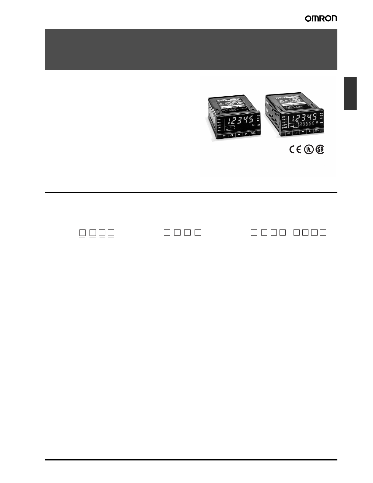
Up/Down Counting Meter
K3NC
An Ideal Interface for High-speed Up/Down
Counting and Serial Communications
• 50-kHz input range for high-speed signal processing.
• A wide selection of outputs: relay, transistor, BCD, linear, or
communications.
• Prescale function available, which displays in units of actual
physical parameters (length, volume, etc.).
• Built-in sensor power supply (12 VDC, 80 mA).
• Banks with four set values and four prescale values.
• Five-stage comparative outputs available.
• Compact 1/8 DIN size.
• Conforms to EMC standards, EN61010-1 (IEC1010-1).
• UL/CSA approved.
®
Model Number Structure
■ Model Number Legend
Base Units and Output Boards can be ordered individually or as sets. Refer to the Output Board Combinations table on page 130.
1, 2. Input Sensors Codes
NB: NPN inputs/Voltage pulse inputs
PB: PNP inputs
3. Supply Voltage
1: 100 to 240 VAC
2: 12 to 24 VDC
4. Display
A: Basic
C: Set Value LED Display
5, 6, 7, 8. Output Type Codes
C2: 5 comparative relay contact outputs (OUT1, 2, 4, 5: SPST-
NO; OUT3: SPDT)
C5: 5 comparative relay contact outputs (OUT1, 2, 4, 5: SPST-
NC; OUT3: SPDT)
T1: 5 comparative transistor outputs (NPN open collector)
T2: 5 comparative transistor outputs (PNP open collector)
B2: BCD output (NPN open collector) (see note)
B4: BCD output + 5 transistor outputs (NPN open collector)
L1: Linear output (4 to 20 mA) (see note)
L2: Linear output (1 to 5 VDC) (see note)
L3: Linear output (1 mV/10 digits) (see note)
L4: Linear output, 4 to 20 mA + 5 transistor outputs (NPN open
collector)
L5: Linear output, 1 to 5 V + 5 transistor outputs (NPN open col-
lector)
L6: Linear output, 1 mV/10 digits+ 5 transistor outputs (NPN
open collector)
L7: Linear output, 0 to 5 VDC (see note)
L8: Linear output, 0 to 10 VDC (see note)
L9: Linear output, 0 to 5 VDC + 5 transistor outputs (NPN open
collector)
L10: Linear output, 0 to 10 VDC + 5 transistor outputs (NPN open
collector)
FLK1: Communication RS-232C (see note)
FLK2: Communication RS-485 (see note)
FLK3: Communication RS-422 (see note)
FLK4: RS-232C + 5 transistor outputs (NPN open collector)
FLK5: RS-485 + 5 transistor outputs (NPN open collector)
FLK6: RS-422 + 5 transistor outputs (NPN open collector)
Note: These output types are available on Basic Models only.
1234
1
2345678
5
678
K3NC -
Base Units
K3NC - -
Base Units with Output Boards
K31 -
Output Boards
C-130 Up/Down Counting Meter K3NC
Ordering Information
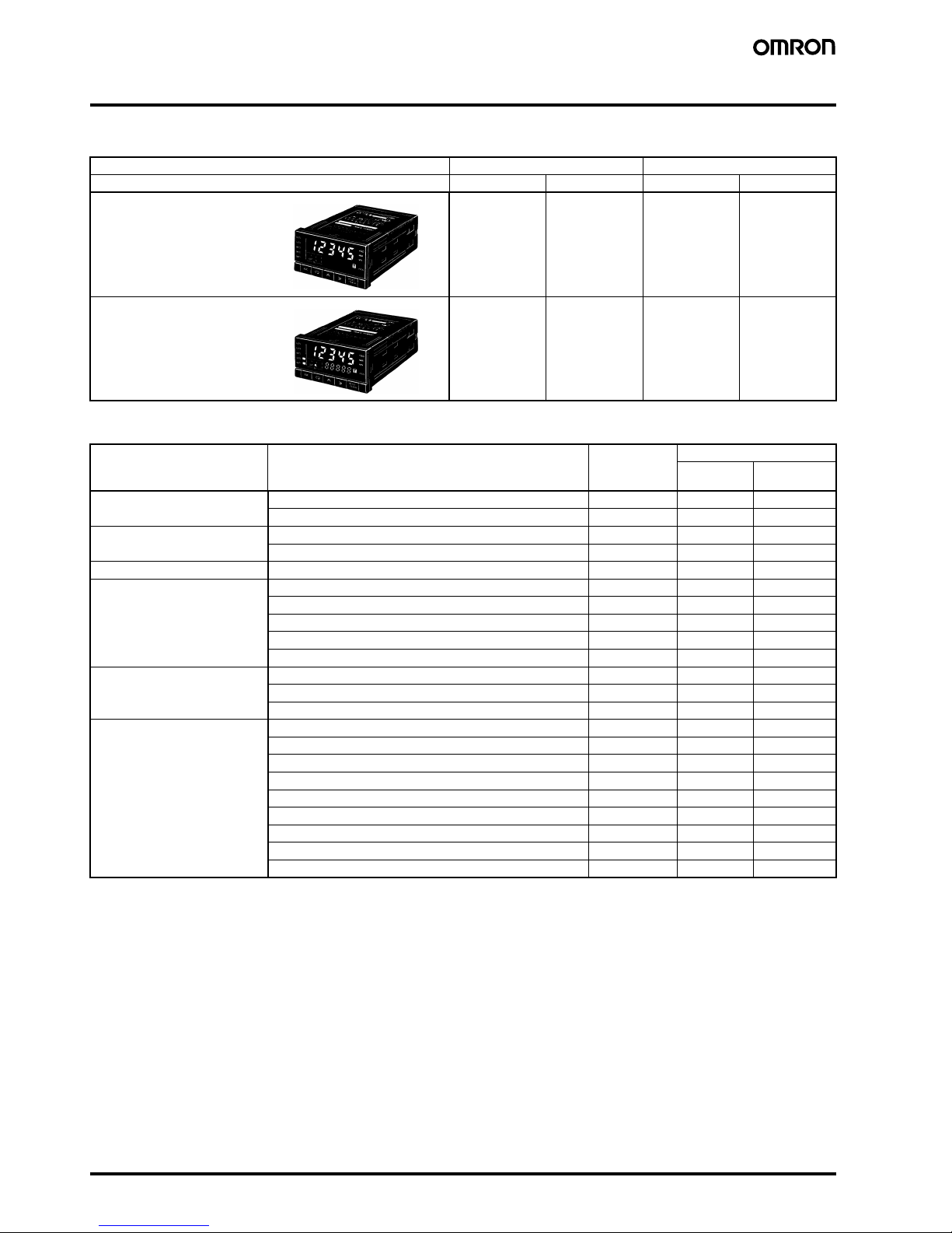
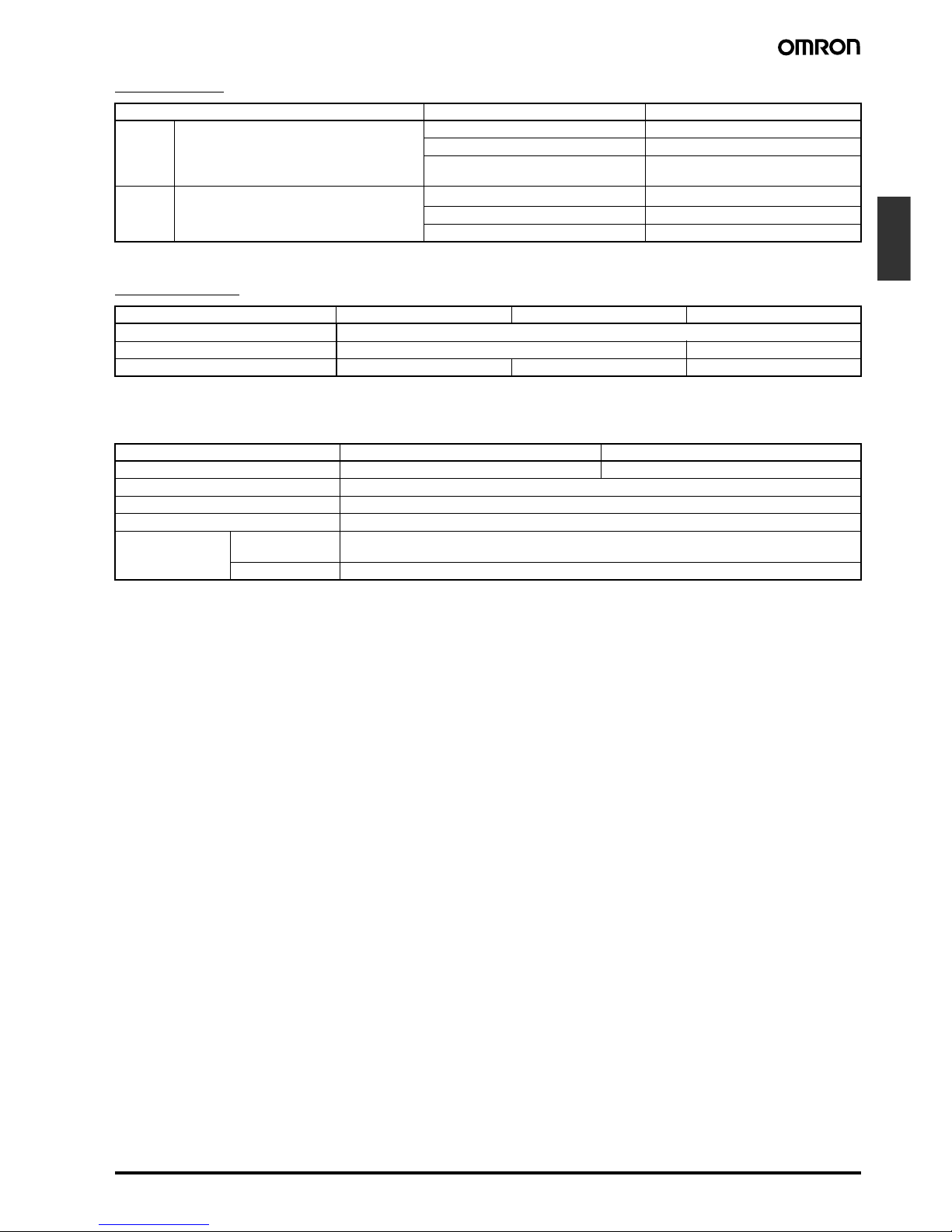
■ Base Unit
■ Available Output Board Combinations
Note: For details, refer to the Communication Operation Manual.
Input type NPN/Voltage pulse PNP
Supply voltage 100 to 240 VAC 12 to 24 VDC 100 to 240 VAC 12 to 24 VDC
K3NC-NB1A K3NC-NB2A K3NC-PB1A K3NC-PB2A
K3NC-NB1C K3NC-NB2C K3NC-PB1C K3NC-PB2C
Output type Output configuration Output boards Base units
Basic Set Value
LED Display
Relay contact 5 outputs: OUT1, 2, 4, 5 (SPST-NO), and OUT3 (SPDT) K31-C2 Yes Yes
5 outputs: OUT1, 2, 4, 5 (SPST-NC), and OUT3 (SPDT) K31-C5 Yes Yes
Transistor 5 outputs (NPN open collector) K31-T1 Yes Yes
5 outputs (PNP open collector) K31-T2 Yes Yes
BCD (see note) 5-digit output (NPN open collector) K31-B2 Yes ---
Linear 4 to 20 mA DC K31-L1 Yes ---
1 to 5 VDC K31-L2 Yes --1 mV/10 digits K31-L3 Yes --0 to 5 VDC K31-L7 Yes --0 to 10 VDC K31-L8 Yes ---
Communication boards
(see note)
RS-232C K31-FLK1 Yes --RS-485 K31-FLK2 Yes --RS-422 K31-FLK3 Yes ---
Combination output and
communication boards
BCD output + 5 transistor outputs (NPN open collector) K31-B4 Yes Yes
4 to 20 mA + 5 transistor outputs (NPN open collector) K31-L4 Yes Yes
1 to 5 V + 5 transistor outputs (NPN open collector) K31-L5 Yes Yes
1 mV/10 digits + 5 transistor outputs (NPN open collector) K31-L6 Yes Yes
0 to 5 VDC + 5 transistor outputs (NPN open collector) K31-L9 Yes Yes
0 to 10 VDC + 5 transistor outputs (NPN open collector) K31-L10 Yes Yes
RS-232C + 5 transistor outputs (NPN open collector) K31-FLK4 Yes Yes
RS-485 + 5 transistor outputs (NPN open collector) K31-FLK5 Yes Yes
RS-422 + 5 transistor outputs (NPN open collector) K31-FLK6 Yes Yes
Basic Models
These models provide a present
value LED and front-panel control
keys. Can be connected to any
Output Board, or can be used for
display only without an Output
Board.
Set Value LED Models
These models provide a
present value LED, set value
LED, and front-panel control
keys. Can be connected to
Relay, Transistor, or
Combination Output Boards.
Up/Down Counting Meter K3NC C-131
Counters
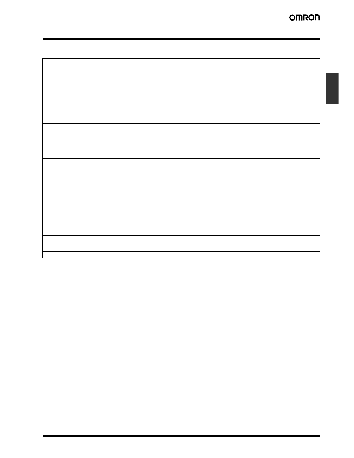
Specifications
■ Ratings
Note: A K3NC with DC supply voltage requires approximately 1 A DC as control power supply current the moment the K3NC is turned ON. Do not
forget to take this into consideration when using several K3NC units. When the K3NC is not in measuring operation (e.g., the K3NC has
been just turned ON or is operating for startup compensation time), the display will read “00000” and all outputs will be OFF.
Supply voltage 100 to 240 VAC (50/60 Hz); 12 to 24 VDC
Operating voltage range 85% to 110% of supply voltage
Power consumption (see note) 15 VA max. (max. AC load with all indicators lit)
10 W max. (max. DC load with all indicators lit)
Sensor power supply 80 mA at 12 VDC±10%
Insulation resistance 20 MΩ min. (at 500 VDC) between external terminal and case.
Insulation provided between inputs, outputs, and power supply.
Dielectric strength 2,000 VAC for 1 min between external terminal and case.
Insulation provided between inputs, outputs, and power supply.
Noise immunity ±1,500 V on power supply terminals in normal or common mode ±1 µs, 100 ns for square-wave noise
with 1 ns
Vibration resistance Malfunction: 10 to 55 Hz, 0.5-mm for 10 min each in X, Y, and Z directions
Destruction: 10 to 55 Hz, 0.75-mm for 2 hrs each in X, Y, and Z directions
Shock resistance
Malfunction: 98 m/s
2
for 3 times each in X, Y, and Z directions
Destruction: 294 m/s
2
for 3 times each in X, Y, and Z directions
Ambient temperature Operating: −10°C to 55°C (with no icing)
Storage: −20°C to 65°C (with no icing)
Ambient humidity Operating: 25% to 85% (with no condensation)
EMC (EMI) EN61326+A1 Industry
Emission Enclosure: CISPR 11 Group 1 class A: CISRP16-1/-2
Emission AC Mains: CISPR 11 Group 1 class A: CISRP16-1/-2
(EMS) EN61326+A1 Industry
Immunity ESD: EN61000-4-2: 4 kV contact discharge (level 2)
8 kV air discharge (level 3)
Immunity RF-interference: EN61000-4-3: 10 V/m (amplitude-modulated,
80 MHz to 1 GHz) (level 3)
Immunity Fast Transient Noise: EN61000-4-4: 2 kV (power line) (level 3)
Immunity Burst Noise: 1 kV line to line (I/O signal line)
Immunity Surge: EN61000-4-5: 1 kV line to line
2 kV line to ground (power line)
Immunity Conducted Disturbance EN61000-4-6: 3 V (0.15 to 80 MHz) (level 2)
Immunity Voltage Dip/Interrupting EN61000-4-11: 0.5 cycles, 0, 180°, 100% (rated voltage)
Approved standards UL508, CSA22.2;
Conforms to EN61326+A1, EN61010-1 (IEC61010-1)
Conforms to VDE0106/P100 (finger protection) when the terminal cover is mounted.
Weight Approx. 400 g
C-132 Up/Down Counting Meter K3NC
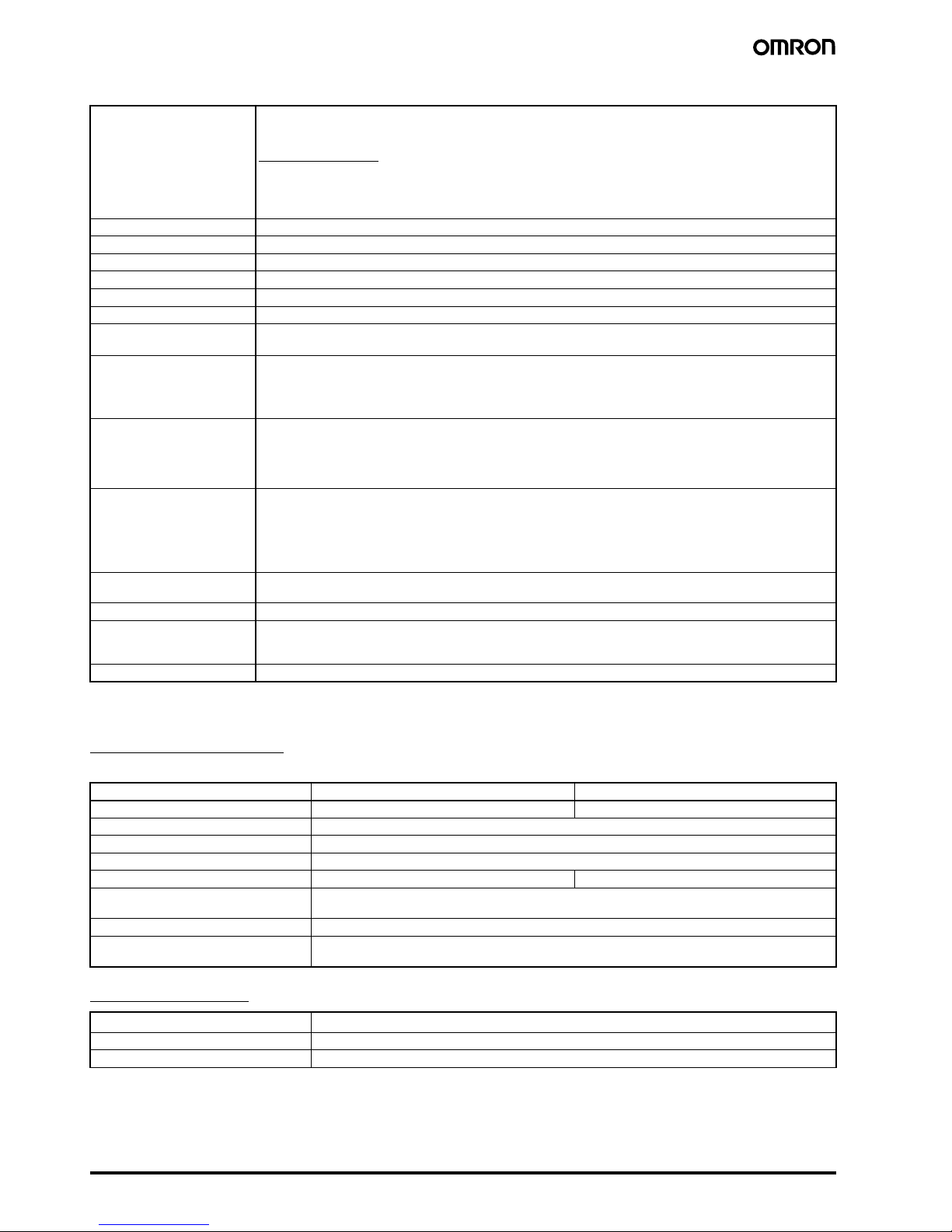
■ Characteristics
■ Input/Output Ratings
Relay Contact Output
(Incorporating a G6B Relay)
Transistor Output
Input signal No-voltage contact (30 Hz max., ON/OFF pulse width: 15 ms min.)
Voltage pulse (50 kHz max., ON/OFF pulse width: 9 µs min., ON voltage: 4.5 to 30 V/OFF voltage: −30 to 2 V)
Open collector (50 kHz max., ON/OFF pulse width: 9 µs min.)
Connectable Sensors
ON residual voltage: 3 V max.
OFF leakage current: 1.5 mA max.
Load current: Must have switching capacity of 20 mA min.
Must be able to dependably switch a load current of 5 mA max.
Input mode Up/Down B (individual inputs), Up/Down C (phase difference inputs)
Output mode ALL-H/ALL-L
Max. displayed digits 5 digits (−19999 to 99999)
Display 7-segment LED
Polarity display “−” is displayed automatically with a negative input signal.
Zero display Leading zeros are not displayed.
Prescale function
Programming via front-panel key inputs. (0.0001 x 10
−9
to 9.9999 x 10⁹, decimal point can be set freely)
Can be set using prescale value teaching.
External control RESET: 16 ms max. (external reset signal)
COMPENSATION: 16 ms max. (external compensation signal)
BANK 1, 2: 100 ms max. (bank switching time)
Up to 4 set value or prescale value banks available
Other functions Variable linear output range (for models with linear outputs only)
Remote/Local processing (available for communications output models only)
Counting value reset with front panel keys
Security
Memory power failure
Output configuration Relay contact output (5 outputs)
Transistor output (NPN and PNP open collector), BCD (NPN open collector)
Parallel BCD (NPN open collector) + transistor output (NPN open collector)
Linear output (4 to 20 mA, 1 to 5 V) + transistor output (NPN open collector)
Communication functions (RS-232C, RS-485, RS-422)
Communication functions (RS-232C, RS-485, RS-422) + transistor output (NPN open collector)
Delay in comparative
outputs
1 ms max. (at transistor output),
10 ms max. (at relay output)
Linear output response time 20 ms max.
Degree of protection Front panel: NEMA4 for indoor use (equivalent to IP66)
Rear case: IEC standard IP20
Terminals: IEC standard IP00
Memory protection Non-volatile memory (EEPROM) (possible to rewrite 100,000 times)
Item Resistive load (cosφ = 1) Inductive load (cosφ = 0.4, L/R = 7 ms)
Rated load 5 A at 250 VAC; 5 A at 30 VDC 1.5 A at 250 VAC, 1.5 A at 30 VDC
Rated carry current 5 A max. (at COM terminal)
Max. contact voltage 380 VAC, 125 VDC
Max. contact current 5 A max. (at COM terminal)
Max. switching capacity 1,250 VA, 150 W 375 VA, 80 W
Min. permissible load
(P level, reference value)
10 mA at 5 VDC
Mechanical life 50,000,000 times min. (at a switching frequency of 18,000 times/hr)
Electrical life
(at an ambient temperature of 23°C)
100,000 times min. (at a rated load switching frequency of 1,800 times/hr)
Rated load voltage
12 to 24 VDC
+10%
/
-15%
Max. load current 50 mA
Leakage current 100 µA max.
Up/Down Counting Meter K3NC C-133
Counters
BCD Output
Note: Logic method: negative logic
Linear Output
Note: For the 1 mV/10-digit output, the output voltage changes for every 40 to 50 increment in the display value.
■ Communications Specifications
For details, refer to Communication Operation Manual.
I/O signal name Item Rating
Inputs REQUEST, COMPENSATION, RESET Input signal No-voltage contact input
Input current with no-voltage input 10 mA
Signal level ON voltage: 1.5 V max.
OFF voltage: 3 V min.
Outputs DATA, POLARITY, OVERFLOW, DATA VALID,
RUN
Rated load voltage
12 to 24 VDC
+10%
/
-15%
Max. load current 10 mA
Leakage current 100 µA max.
Item 4 to 20 mA 1 to 5 V 1 mV/10 digits (see note)
Resolution 4,096
Output error ±0.5% FS ±1.5% FS
Permissible load resistance 600 Ω max. 500 Ω min. 1 KΩ min.
Item RS-232C, RS-422 RS-485
Transmission method 4-wire, half-duplex 2-wire, half-duplex
Synchronization method Start-stop synchronization
Baud rate 1,200/2,400/4,800/9,600/19,200/38,400 bps
Transmission code ASCII (7-bit)
Communications Write Comparative set value, prescaling value, remote/local programming, reset control, and other setting
mode items excluding communications conditions.
Read Process value, comparative set value, model data, error code, and others
C-134 Up/Down Counting Meter K3NC
Connections
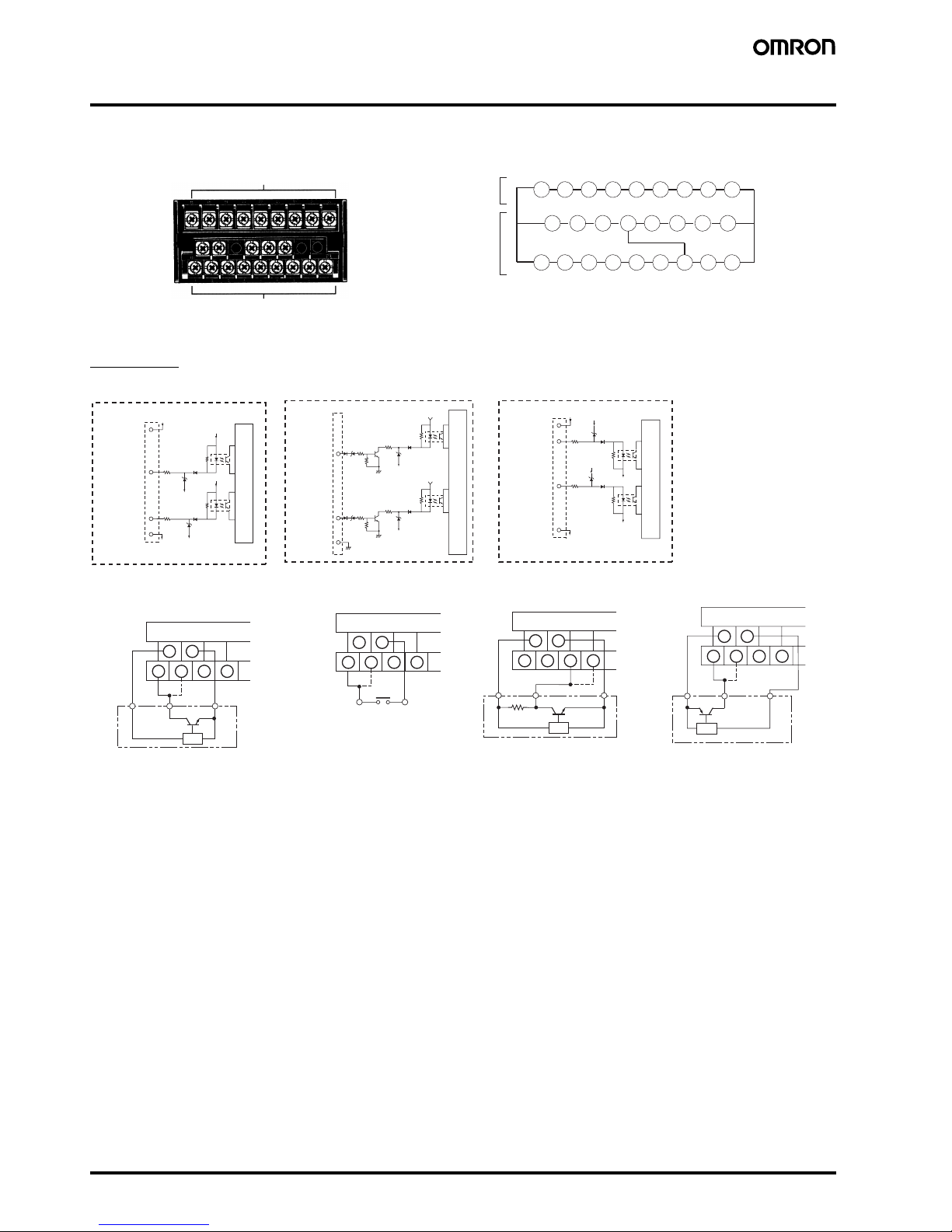
■ Terminal Arrangement
Input Unit
18 19 20 21 22 23 24 25 26
10 11 12 13 14 15 16 17
1 2 3 4 5 6 7 8 9
Terminal Numbers
Output unit
Input unit
Output
unit
Input
unit
Note: Terminals 7 to 13 are connected internally.
Terminals 7 and 11 are mutually isolated.
+12 V
+12 V
590 Ω
590 Ω
820 Ω
820 Ω
+12 V
10
1
2
11
GND
GND
+12 V
590 Ω
820 Ω
3
GND
10 k Ω
+12 V
590 Ω
820 Ω
4
11
GND
10 k Ω
+12 V
+12 V
590 Ω
820 Ω
10
1
2
11
GND
GND
GND
590 Ω
820 Ω
External
sensor
power
supply (+)
Input A
Input B
External
sensor
power
supply (−)
Internal circuits
Voltage Pulse Inputs
Input A
Input B
Internal circuits
PNP-input Models
External
sensor
power
supply (+)
Input A
Input B
External
sensor
power
supply (−)
Internal circuits
NPN Inputs
10 1 1
1234
+12 V
INA INB
0 V
10 11
1234
INA INB GND
10 11
1234
+12V
INA INB
0 V
+12V
INA INB
0 V
10 11
1234
Contact
NPN output sensor
PNP output sensor
Contact Output Voltage Output PNP Open Collector OutputNPN Open Collector Output
(NPN Linear 2-wire Output)
Note: Connect the + side of the NPN
linear 2-wire input to terminal 1
and the − side to terminal 11.
Note: With voltage pulse input
not from a 3-wire sensor,
connect the + side to terminal 3 and the − side to
terminal 11.
Note: When the contact is short-
circuited, a current of approximately 13 mA will flow at a voltage of approximately 12 V.
Input resistance: 10 kΩ
Voltage pulse output sensor
Up/Down Counting Meter K3NC C-135
Counters
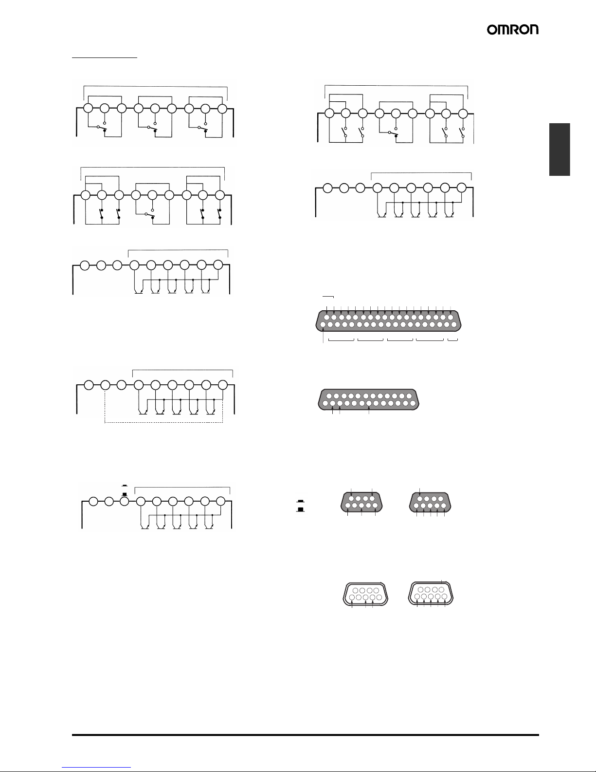
Output Unit
18 19 20 21 22 23 24 25 26
18 19 20 21 22 23 24 25 26
18 19 20 21 22 23 24 25 26
18 19 20 21 22 23 24 25 26
K31-C1: Relay (3 Outputs)
Outputs (5 A max. at 250 VAC)
H PASS L
K31-C2: Relay (5 Outputs)
Outputs (5 A max. at 250 VAC)
K31-C5: Relay (5 Outputs)
Outputs (5 A max. at 250 VAC)
HH PASS L
LLH
HH PASS L
H
LL
K31-T1: Transistor (NPN Open Collector)
Outputs (50 mA max. at 24 VDC)
HH H PASS L LL COM
+ −
18 19 20 21 22 23 24 25 26
18 19 20 21 22 23 24 25 26
10
0
10
1
10
2
10310
4
48
10
4
12 4812481248 1248 12
20
123456789
10 11 12 13 14 15 16 17 18 19
21 22 23 24 25 26 27 28 29 30 31 32 33 34 35 36 37
K31-T2: Transistor (PNP Open Collector)
Outputs (50 mA max. at 24 VDC)
HH H PASS L LL COM
K31-B2, -B4: BCD (NPN Open Collector)
(Terminals 32 to 36 are provided only on K31-B4.
Outputs (50 mA max. at 24 VDC)
HH H PASS L LL COM
COMMON
DATA OVERFLOW
DATA VALID
RUN
COMMON
REQUEST
MAX. REQ.
MIN. REQ.
HOLD
RESET
POLARITYHHH
PASSLLL
COMMON
K31-L1, L2, L3,-L4, -L5, -L6, -L7, -L8, -L9,
-
L10: Linear
(Terminals 21 to 26 are provided only on K31-L4,
-
L5, -L6, -L9, -L10.)
L1, L4: 4 to 20 mA
L2, L5: 1 to 5 V
L3, L6: 1 mV/10 digit
L7, L9: 0 to 5 VDC
L8, L10: 0 to 10 VDC
Note: With K31-L4/-L5/-L6/-L9/-L10 models, terminals
1
9
and 26 are connected internally.
SD
RD
SG
14
123456789
10 11 12 13
15 16 17 18 19 20 21 22 23 24 25
K31-FLK1: RS-232C
+ −
18 19 20 21 22 23 24 25 26
RDA
SDA
RDB
SDB
SG
6
2345
789
6
12345
789
1
K31-FLK2, -FLK5: RS-485
(Terminals 21 to 26 are provided only on K31-FLK5.)
HH H PASS L LL COM
RS-485
Terminator
ON
OFF
Outputs (50 mA max. at 24 VDC)
K31-FLK3, -FLK6: RS-422
(The right connector is provided only on K31-FLK6)
ON
OFF
K31-FLK4: RS-232C + Transistor (NPN Open Collector)
RS-232C
LL
HH
L
COM
H
PA SS
Terminator
RS-422
• D-sub 37P Connectors for BCD output (attachment)
Plug: XM2A-3701
Hood: XM2S-3711
• D-sub 25P connectors for RS-232C output (K31-FLK1) (order
separately)
Plug: XM2A-2501
Hood: XM2S-2511
• D-sub 9P connectors for RS-422 output (K31-FLK3 and K31-
FLK6) (order separately)
Plug: XM2A-0901
Hood: XM2S-0911
• D-sub 9P connectors for RS-232C output (K31-FLK4) (order
separately)
Plug: XM2D-0901
Hood: XM2D-0911
Output NPN Tr.
(50 mA max. at 24 VDC)
Output NPN Tr.
(50 mA max. at 24 VDC)
L
H
PASS
HH
9
4321
87
6
5
LL
RD
SD
SG
COM
9
4321
87
6
5
C-136 Up/Down Counting Meter K3NC
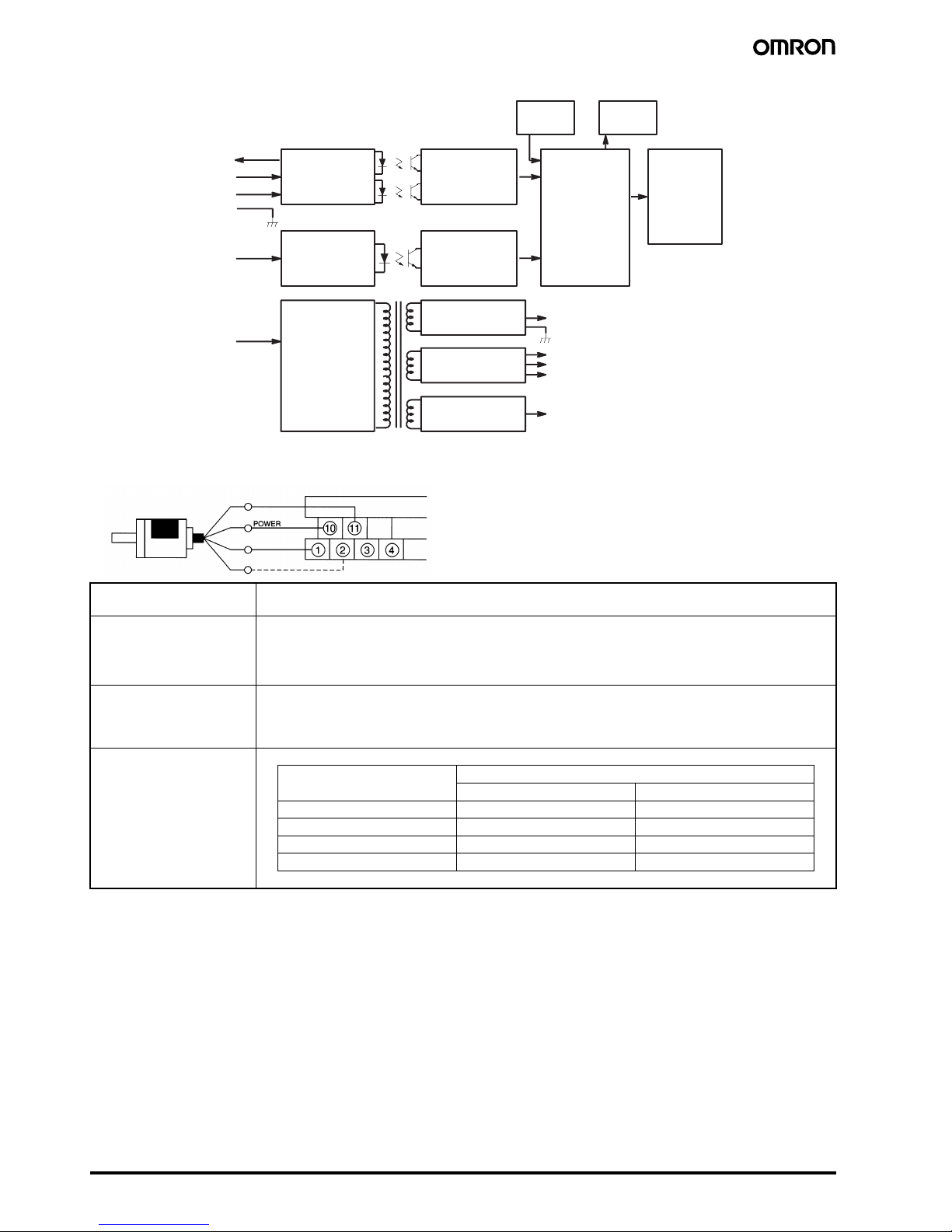
■ Block Diagram
■ Rotary Encoder Connection Example
Input circuit
Sensor A
Sensor B
GND
Control input
Frequency measurement circuit
Waveform adjustment circuit
8-bit microcomputer
Control input circuit
Power supply
for sensor
Control power
supply
Control input
circuit
Power supply
circuit
Frequency
measurement
circuit
Wavefo rm
adjustment
circuit
Voltage stabilizing
circuit
Voltage stabilizing
circuit
Voltage stabilizing
circuit
LED
Key
switch
8-bit
microcomputer
Output
circuit
Power supply for
sensor (input circuit)
0 V
Phase A
Phase B
INA/INB Counts input signals.
Accepts Up/Down (individual or phase difference) inputs.
RESET Resets the present value to zero.
No counting inputs are accepted when a RESET input is ON.
RESET is lit when a RESET input is ON.
Note: External reset minimum signal width: 16 ms
COMPENSATION Resets the present counting value to the compensation value at the rising edge of a compensation input. In the
compensation value setting parameter, it is possible to set to “Effective during incrementing and decrementing a
count” or to “Effective only during incrementing a count.”
Note: External compensation input minimum signal width: 16 ms
BANK 1, 2 Selects one of the four banks.
Bank no. Control input
Bank 1 Bank 2
1OFFOFF
2ONOFF
3OFFON
4ONON
Note: Bank switching minimum signal width: 100 ms max.
 Loading...