

Page 1
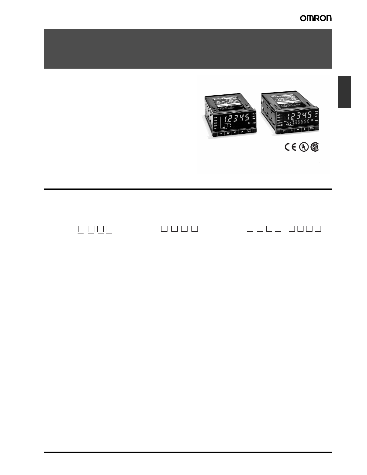
Up/Down Counting Meter K3NC C-129
Counters
Up/Down Counting Meter
K3NC
An Ideal Interface for High-speed Up/Down
Counting and Serial Communications
• 50-kHz input range for high-speed signal processing.
• A wide selection of outputs: relay, transistor, BCD, linear, or
communications.
• Prescale function available, which displays in units of actual
physical parameters (length, volume, etc.).
• Built-in sensor power supply (12 VDC, 80 mA).
• Banks with four set values and four prescale values.
• Five-stage comparative outputs available.
• Compact 1/8 DIN size.
• Conforms to EMC standards, EN61010-1 (IEC1010-1).
• UL/CSA approved.
®
Model Number Structure
■ Model Number Legend
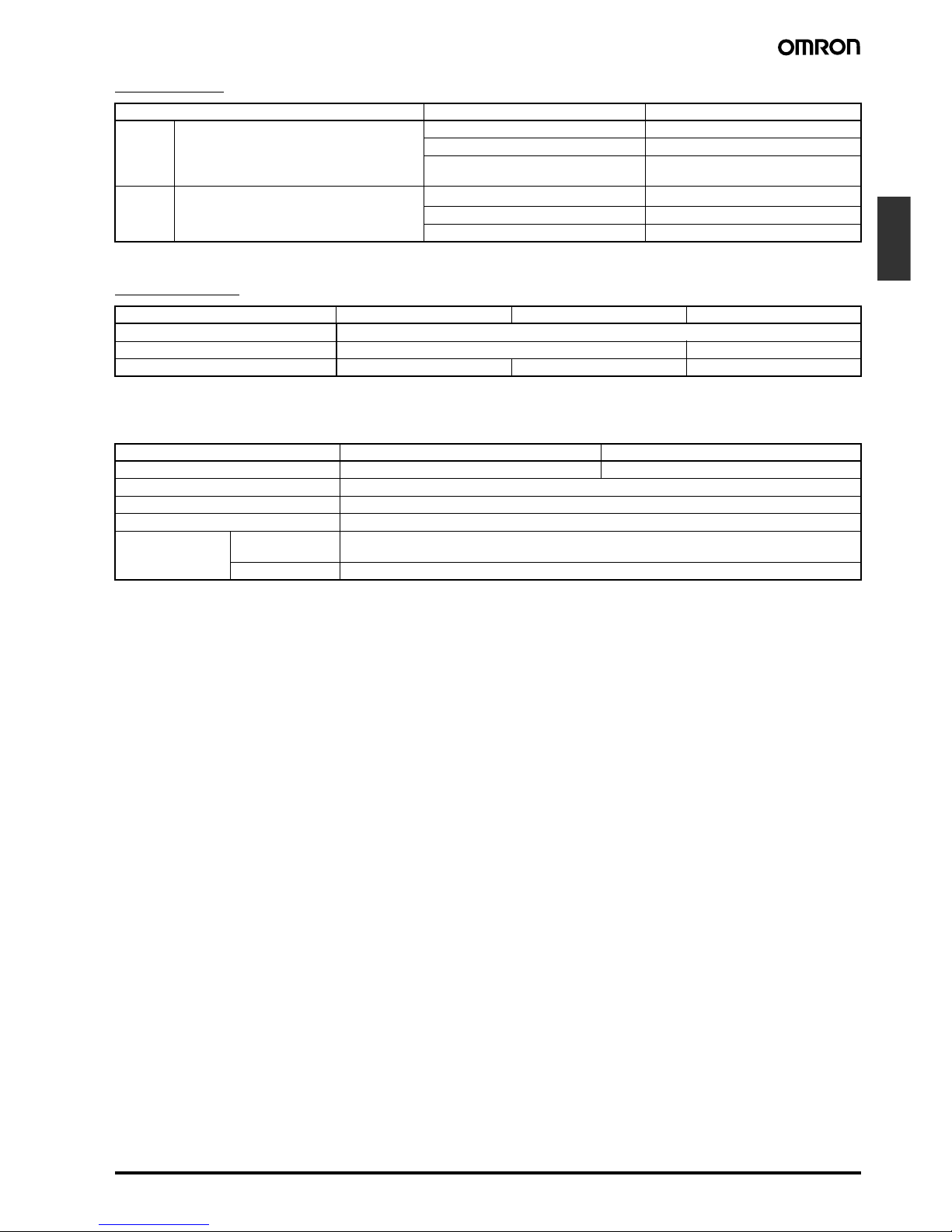
Base Units and Output Boards can be ordered individually or as sets. Refer to the Output Board Combinations table on page 130.
1, 2. Input Sensors Codes
NB: NPN inputs/Voltage pulse inputs
PB: PNP inputs
3. Supply Voltage
1: 100 to 240 VAC
2: 12 to 24 VDC
4. Display
A: Basic
C: Set Value LED Display
5, 6, 7, 8. Output Type Codes
C2: 5 comparative relay contact outputs (OUT1, 2, 4, 5: SPST-
NO; OUT3: SPDT)
C5: 5 comparative relay contact outputs (OUT1, 2, 4, 5: SPST-
NC; OUT3: SPDT)
T1: 5 comparative transistor outputs (NPN open collector)
T2: 5 comparative transistor outputs (PNP open collector)
B2: BCD output (NPN open collector) (see note)
B4: BCD output + 5 transistor outputs (NPN open collector)
L1: Linear output (4 to 20 mA) (see note)
L2: Linear output (1 to 5 VDC) (see note)
L3: Linear output (1 mV/10 digits) (see note)
L4: Linear output, 4 to 20 mA + 5 transistor outputs (NPN open
collector)
L5: Linear output, 1 to 5 V + 5 transistor outputs (NPN open col-
lector)
L6: Linear output, 1 mV/10 digits+ 5 transistor outputs (NPN
open collector)
L7: Linear output, 0 to 5 VDC (see note)
L8: Linear output, 0 to 10 VDC (see note)
L9: Linear output, 0 to 5 VDC + 5 transistor outputs (NPN open
collector)
L10: Linear output, 0 to 10 VDC + 5 transistor outputs (NPN open
collector)
FLK1: Communication RS-232C (see note)
FLK2: Communication RS-485 (see note)
FLK3: Communication RS-422 (see note)
FLK4: RS-232C + 5 transistor outputs (NPN open collector)
FLK5: RS-485 + 5 transistor outputs (NPN open collector)
FLK6: RS-422 + 5 transistor outputs (NPN open collector)
Note: These output types are available on Basic Models only.
1234
1
2345678
5
678
K3NC -
Base Units
K3NC - -
Base Units with Output Boards
K31 -
Output Boards
Page 2
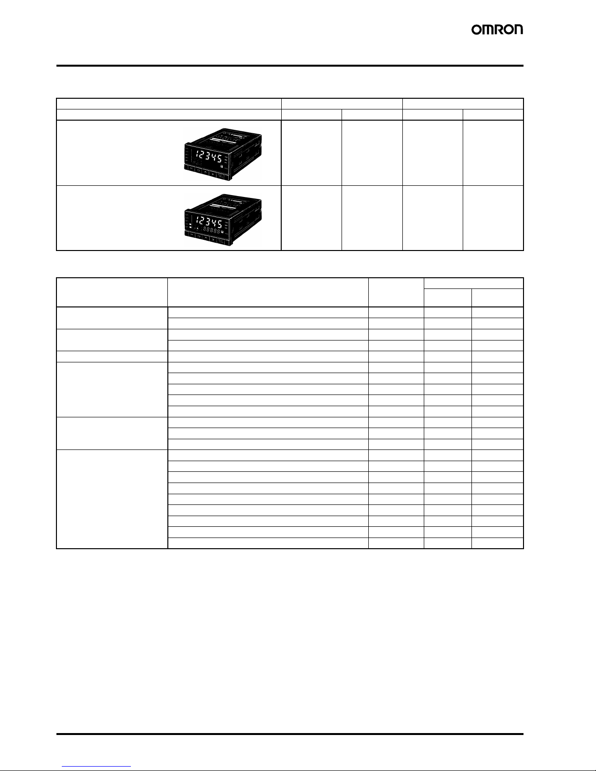
C-130 Up/Down Counting Meter K3NC
Ordering Information
■ Base Unit
■ Available Output Board Combinations
Note: For details, refer to the Communication Operation Manual.
Input type NPN/Voltage pulse PNP
Supply voltage 100 to 240 VAC 12 to 24 VDC 100 to 240 VAC 12 to 24 VDC
K3NC-NB1A K3NC-NB2A K3NC-PB1A K3NC-PB2A
K3NC-NB1C K3NC-NB2C K3NC-PB1C K3NC-PB2C
Output type Output configuration Output boards Base units
Basic Set Value
LED Display
Relay contact 5 outputs: OUT1, 2, 4, 5 (SPST-NO), and OUT3 (SPDT) K31-C2 Yes Yes
5 outputs: OUT1, 2, 4, 5 (SPST-NC), and OUT3 (SPDT) K31-C5 Yes Yes
Transistor 5 outputs (NPN open collector) K31-T1 Yes Yes
5 outputs (PNP open collector) K31-T2 Yes Yes
BCD (see note) 5-digit output (NPN open collector) K31-B2 Yes ---
Linear 4 to 20 mA DC K31-L1 Yes ---
1 to 5 VDC K31-L2 Yes --1 mV/10 digits K31-L3 Yes --0 to 5 VDC K31-L7 Yes --0 to 10 VDC K31-L8 Yes ---
Communication boards
(see note)
RS-232C K31-FLK1 Yes --RS-485 K31-FLK2 Yes --RS-422 K31-FLK3 Yes ---
Combination output and
communication boards
BCD output + 5 transistor outputs (NPN open collector) K31-B4 Yes Yes
4 to 20 mA + 5 transistor outputs (NPN open collector) K31-L4 Yes Yes
1 to 5 V + 5 transistor outputs (NPN open collector) K31-L5 Yes Yes
1 mV/10 digits + 5 transistor outputs (NPN open collector) K31-L6 Yes Yes
0 to 5 VDC + 5 transistor outputs (NPN open collector) K31-L9 Yes Yes
0 to 10 VDC + 5 transistor outputs (NPN open collector) K31-L10 Yes Yes
RS-232C + 5 transistor outputs (NPN open collector) K31-FLK4 Yes Yes
RS-485 + 5 transistor outputs (NPN open collector) K31-FLK5 Yes Yes
RS-422 + 5 transistor outputs (NPN open collector) K31-FLK6 Yes Yes
Basic Models
These models provide a present
value LED and front-panel control
keys. Can be connected to any
Output Board, or can be used for
display only without an Output
Board.
Set Value LED Models
These models provide a
present value LED, set value
LED, and front-panel control
keys. Can be connected to
Relay, Transistor, or
Combination Output Boards.
Page 3
Up/Down Counting Meter K3NC C-131
Counters
Specifications
■ Ratings
Note: A K3NC with DC supply voltage requires approximately 1 A DC as control power supply current the moment the K3NC is turned ON. Do not
forget to take this into consideration when using several K3NC units. When the K3NC is not in measuring operation (e.g., the K3NC has
been just turned ON or is operating for startup compensation time), the display will read “00000” and all outputs will be OFF.
Supply voltage 100 to 240 VAC (50/60 Hz); 12 to 24 VDC
Operating voltage range 85% to 110% of supply voltage
Power consumption (see note) 15 VA max. (max. AC load with all indicators lit)
10 W max. (max. DC load with all indicators lit)
Sensor power supply 80 mA at 12 VDC±10%
Insulation resistance 20 MΩ min. (at 500 VDC) between external terminal and case.
Insulation provided between inputs, outputs, and power supply.
Dielectric strength 2,000 VAC for 1 min between external terminal and case.
Insulation provided between inputs, outputs, and power supply.
Noise immunity ±1,500 V on power supply terminals in normal or common mode ±1 µs, 100 ns for square-wave noise
with 1 ns
Vibration resistance Malfunction: 10 to 55 Hz, 0.5-mm for 10 min each in X, Y, and Z directions
Destruction: 10 to 55 Hz, 0.75-mm for 2 hrs each in X, Y, and Z directions
Shock resistance
Malfunction: 98 m/s
2
for 3 times each in X, Y, and Z directions
Destruction: 294 m/s
2
for 3 times each in X, Y, and Z directions
Ambient temperature Operating: −10°C to 55°C (with no icing)
Storage: −20°C to 65°C (with no icing)
Ambient humidity Operating: 25% to 85% (with no condensation)
EMC (EMI) EN61326+A1 Industry
Emission Enclosure: CISPR 11 Group 1 class A: CISRP16-1/-2
Emission AC Mains: CISPR 11 Group 1 class A: CISRP16-1/-2
(EMS) EN61326+A1 Industry
Immunity ESD: EN61000-4-2: 4 kV contact discharge (level 2)
8 kV air discharge (level 3)
Immunity RF-interference: EN61000-4-3: 10 V/m (amplitude-modulated,
80 MHz to 1 GHz) (level 3)
Immunity Fast Transient Noise: EN61000-4-4: 2 kV (power line) (level 3)
Immunity Burst Noise: 1 kV line to line (I/O signal line)
Immunity Surge: EN61000-4-5: 1 kV line to line
2 kV line to ground (power line)
Immunity Conducted Disturbance EN61000-4-6: 3 V (0.15 to 80 MHz) (level 2)
Immunity Voltage Dip/Interrupting EN61000-4-11: 0.5 cycles, 0, 180°, 100% (rated voltage)
Approved standards UL508, CSA22.2;
Conforms to EN61326+A1, EN61010-1 (IEC61010-1)
Conforms to VDE0106/P100 (finger protection) when the terminal cover is mounted.
Weight Approx. 400 g
Page 4
C-132 Up/Down Counting Meter K3NC
■ Characteristics
■ Input/Output Ratings
Relay Contact Output
(Incorporating a G6B Relay)
Transistor Output
Input signal No-voltage contact (30 Hz max., ON/OFF pulse width: 15 ms min.)
Voltage pulse (50 kHz max., ON/OFF pulse width: 9 µs min., ON voltage: 4.5 to 30 V/OFF voltage: −30 to 2 V)
Open collector (50 kHz max., ON/OFF pulse width: 9 µs min.)
Connectable Sensors
ON residual voltage: 3 V max.
OFF leakage current: 1.5 mA max.
Load current: Must have switching capacity of 20 mA min.
Must be able to dependably switch a load current of 5 mA max.
Input mode Up/Down B (individual inputs), Up/Down C (phase difference inputs)
Output mode ALL-H/ALL-L
Max. displayed digits 5 digits (−19999 to 99999)
Display 7-segment LED
Polarity display “−” is displayed automatically with a negative input signal.
Zero display Leading zeros are not displayed.
Prescale function
Programming via front-panel key inputs. (0.0001 x 10
−9
to 9.9999 x 10⁹, decimal point can be set freely)
Can be set using prescale value teaching.
External control RESET: 16 ms max. (external reset signal)
COMPENSATION: 16 ms max. (external compensation signal)
BANK 1, 2: 100 ms max. (bank switching time)
Up to 4 set value or prescale value banks available
Other functions Variable linear output range (for models with linear outputs only)
Remote/Local processing (available for communications output models only)
Counting value reset with front panel keys
Security
Memory power failure
Output configuration Relay contact output (5 outputs)
Transistor output (NPN and PNP open collector), BCD (NPN open collector)
Parallel BCD (NPN open collector) + transistor output (NPN open collector)
Linear output (4 to 20 mA, 1 to 5 V) + transistor output (NPN open collector)
Communication functions (RS-232C, RS-485, RS-422)
Communication functions (RS-232C, RS-485, RS-422) + transistor output (NPN open collector)
Delay in comparative
outputs
1 ms max. (at transistor output),
10 ms max. (at relay output)
Linear output response time 20 ms max.
Degree of protection Front panel: NEMA4 for indoor use (equivalent to IP66)
Rear case: IEC standard IP20
Terminals: IEC standard IP00
Memory protection Non-volatile memory (EEPROM) (possible to rewrite 100,000 times)
Item Resistive load (cosφ = 1) Inductive load (cosφ = 0.4, L/R = 7 ms)
Rated load 5 A at 250 VAC; 5 A at 30 VDC 1.5 A at 250 VAC, 1.5 A at 30 VDC
Rated carry current 5 A max. (at COM terminal)
Max. contact voltage 380 VAC, 125 VDC
Max. contact current 5 A max. (at COM terminal)
Max. switching capacity 1,250 VA, 150 W 375 VA, 80 W
Min. permissible load
(P level, reference value)
10 mA at 5 VDC
Mechanical life 50,000,000 times min. (at a switching frequency of 18,000 times/hr)
Electrical life
(at an ambient temperature of 23°C)
100,000 times min. (at a rated load switching frequency of 1,800 times/hr)
Rated load voltage
12 to 24 VDC
+10%
/
-15%
Max. load current 50 mA
Leakage current 100 µA max.
Page 5
Up/Down Counting Meter K3NC C-133
Counters
BCD Output
Note: Logic method: negative logic
Linear Output
Note: For the 1 mV/10-digit output, the output voltage changes for every 40 to 50 increment in the display value.
■ Communications Specifications
For details, refer to Communication Operation Manual.
I/O signal name Item Rating
Inputs REQUEST, COMPENSATION, RESET Input signal No-voltage contact input
Input current with no-voltage input 10 mA
Signal level ON voltage: 1.5 V max.
OFF voltage: 3 V min.
Outputs DATA, POLARITY, OVERFLOW, DATA VALID,
RUN
Rated load voltage
12 to 24 VDC
+10%
/
-15%
Max. load current 10 mA
Leakage current 100 µA max.
Item 4 to 20 mA 1 to 5 V 1 mV/10 digits (see note)
Resolution 4,096
Output error ±0.5% FS ±1.5% FS
Permissible load resistance 600 Ω max. 500 Ω min. 1 KΩ min.
Item RS-232C, RS-422 RS-485
Transmission method 4-wire, half-duplex 2-wire, half-duplex
Synchronization method Start-stop synchronization
Baud rate 1,200/2,400/4,800/9,600/19,200/38,400 bps
Transmission code ASCII (7-bit)
Communications Write Comparative set value, prescaling value, remote/local programming, reset control, and other setting
mode items excluding communications conditions.
Read Process value, comparative set value, model data, error code, and others
Page 6
C-134 Up/Down Counting Meter K3NC
Connections
■ Terminal Arrangement
Input Unit
18 19 20 21 22 23 24 25 26
10 11 12 13 14 15 16 17
1 2 3 4 5 6 7 8 9
Terminal Numbers
Output unit
Input unit
Output
unit
Input
unit
Note: Terminals 7 to 13 are connected internally.
Terminals 7 and 11 are mutually isolated.
+12 V
+12 V
590 Ω
590 Ω
820 Ω
820 Ω
+12 V
10
1
2
11
GND
GND
+12 V
590 Ω
820 Ω
3
GND
10 k Ω
+12 V
590 Ω
820 Ω
4
11
GND
10 k Ω
+12 V
+12 V
590 Ω
820 Ω
10
1
2
11
GND
GND
GND
590 Ω
820 Ω
External
sensor
power
supply (+)
Input A
Input B
External
sensor
power
supply (−)
Internal circuits
Voltage Pulse Inputs
Input A
Input B
Internal circuits
PNP-input Models
External
sensor
power
supply (+)
Input A
Input B
External
sensor
power
supply (−)
Internal circuits
NPN Inputs
10 1 1
1234
+12 V
INA INB
0 V
10 11
1234
INA INB GND
10 11
1234
+12V
INA INB
0 V
+12V
INA INB
0 V
10 11
1234
Contact
NPN output sensor
PNP output sensor
Contact Output Voltage Output PNP Open Collector OutputNPN Open Collector Output
(NPN Linear 2-wire Output)
Note: Connect the + side of the NPN
linear 2-wire input to terminal 1
and the − side to terminal 11.
Note: With voltage pulse input
not from a 3-wire sensor,
connect the + side to terminal 3 and the − side to
terminal 11.
Note: When the contact is short-
circuited, a current of approximately 13 mA will flow at a voltage of approximately 12 V.
Input resistance: 10 kΩ
Voltage pulse output sensor
Page 7
Up/Down Counting Meter K3NC C-135
Counters
Output Unit
18 19 20 21 22 23 24 25 26
18 19 20 21 22 23 24 25 26
18 19 20 21 22 23 24 25 26
18 19 20 21 22 23 24 25 26
K31-C1: Relay (3 Outputs)
Outputs (5 A max. at 250 VAC)
H PASS L
K31-C2: Relay (5 Outputs)
Outputs (5 A max. at 250 VAC)
K31-C5: Relay (5 Outputs)
Outputs (5 A max. at 250 VAC)
HH PASS L
LLH
HH PASS L
H
LL
K31-T1: Transistor (NPN Open Collector)
Outputs (50 mA max. at 24 VDC)
HH H PASS L LL COM
+ −
18 19 20 21 22 23 24 25 26
18 19 20 21 22 23 24 25 26
10
0
10
1
10
2
10310
4
48
10
4
12 4812481248 1248 12
20
123456789
10 11 12 13 14 15 16 17 18 19
21 22 23 24 25 26 27 28 29 30 31 32 33 34 35 36 37
K31-T2: Transistor (PNP Open Collector)
Outputs (50 mA max. at 24 VDC)
HH H PASS L LL COM
K31-B2, -B4: BCD (NPN Open Collector)
(Terminals 32 to 36 are provided only on K31-B4.
Outputs (50 mA max. at 24 VDC)
HH H PASS L LL COM
COMMON
DATA OVERFLOW
DATA VALID
RUN
COMMON
REQUEST
MAX. REQ.
MIN. REQ.
HOLD
RESET
POLARITYHHH
PASSLLL
COMMON
K31-L1, L2, L3,-L4, -L5, -L6, -L7, -L8, -L9,
-
L10: Linear
(Terminals 21 to 26 are provided only on K31-L4,
-
L5, -L6, -L9, -L10.)
L1, L4: 4 to 20 mA
L2, L5: 1 to 5 V
L3, L6: 1 mV/10 digit
L7, L9: 0 to 5 VDC
L8, L10: 0 to 10 VDC
Note: With K31-L4/-L5/-L6/-L9/-L10 models, terminals
1
9
and 26 are connected internally.
SD
RD
SG
14
123456789
10 11 12 13
15 16 17 18 19 20 21 22 23 24 25
K31-FLK1: RS-232C
+ −
18 19 20 21 22 23 24 25 26
RDA
SDA
RDB
SDB
SG
6
2345
789
6
12345
789
1
K31-FLK2, -FLK5: RS-485
(Terminals 21 to 26 are provided only on K31-FLK5.)
HH H PASS L LL COM
RS-485
Terminator
ON
OFF
Outputs (50 mA max. at 24 VDC)
K31-FLK3, -FLK6: RS-422
(The right connector is provided only on K31-FLK6)
ON
OFF
K31-FLK4: RS-232C + Transistor (NPN Open Collector)
RS-232C
LL
HH
L
COM
H
PA SS
Terminator
RS-422
• D-sub 37P Connectors for BCD output (attachment)
Plug: XM2A-3701
Hood: XM2S-3711
• D-sub 25P connectors for RS-232C output (K31-FLK1) (order
separately)
Plug: XM2A-2501
Hood: XM2S-2511
• D-sub 9P connectors for RS-422 output (K31-FLK3 and K31-
FLK6) (order separately)
Plug: XM2A-0901
Hood: XM2S-0911
• D-sub 9P connectors for RS-232C output (K31-FLK4) (order
separately)
Plug: XM2D-0901
Hood: XM2D-0911
Output NPN Tr.
(50 mA max. at 24 VDC)
Output NPN Tr.
(50 mA max. at 24 VDC)
L
H
PASS
HH
9
4321
87
6
5
LL
RD
SD
SG
COM
9
4321
87
6
5
Page 8
C-136 Up/Down Counting Meter K3NC
■ Block Diagram
■ Rotary Encoder Connection Example
Input circuit
Sensor A
Sensor B
GND
Control input
Frequency measurement circuit
Waveform adjustment circuit
8-bit microcomputer
Control input circuit
Power supply
for sensor
Control power
supply
Control input
circuit
Power supply
circuit
Frequency
measurement
circuit
Wavefo rm
adjustment
circuit
Voltage stabilizing
circuit
Voltage stabilizing
circuit
Voltage stabilizing
circuit
LED
Key
switch
8-bit
microcomputer
Output
circuit
Power supply for
sensor (input circuit)
0 V
Phase A
Phase B
INA/INB Counts input signals.
Accepts Up/Down (individual or phase difference) inputs.
RESET Resets the present value to zero.
No counting inputs are accepted when a RESET input is ON.
RESET is lit when a RESET input is ON.
Note: External reset minimum signal width: 16 ms
COMPENSATION Resets the present counting value to the compensation value at the rising edge of a compensation input. In the
compensation value setting parameter, it is possible to set to “Effective during incrementing and decrementing a
count” or to “Effective only during incrementing a count.”
Note: External compensation input minimum signal width: 16 ms
BANK 1, 2 Selects one of the four banks.
Bank no. Control input
Bank 1 Bank 2
1OFFOFF
2ONOFF
3OFFON
4ONON
Note: Bank switching minimum signal width: 100 ms max.
Page 9

Up/Down Counting Meter K3NC C-137
Counters
Operation
■ Main Functions
Linear Output Range lset
A linear output range can be set as required. A value corresponding
to the maximum output value and that corresponding to the minimum
output value can be set.
Remote/Local Selection r-l
Select remote programming when performing all settings through the
host devices and select local programming when performing settings
through key operation.
■ BCD Output Timing Chart
A request signal from an external device (such as a Programmable Controller) is required to read BCD data.
Single Sampling Data Output
Approximately 30 ms after the REQ signal rises, a sample is taken and the DATA VALID signal is output. Read the data when the DATA VAL I D
signal is ON.
The DATA VALID signal will turn OFF in 40 ms, and then in 16 ms, the data will go OFF.
Models with a BCD output have an open collector output configuration so that wired-OR connection is possible.
Continuous Data Output
The K3NC outputs each measurement at an interval of 64 ms when
a REQ signal is ON continuously.
20 mA
4 mA
Display
Output
Lower
limit
Upper
limit
For the 4- to 20-mA
output type
40 ms
16 ms
All data "high" All data "high"Data
Approx. 30 ms
DATA
REQ.
DATA
VALID
Pulse with a width of no less than 20 ms.
(no more than 50 ms.)
(1) (2)
(3)
***
K3NC (1)
K3NC (2)
K3NC (3)
DATA
Programmable
controller
DATA (incl. POL and OVER)
and DATA VALID are wired-OR
processed.
The RUN, OUT5, OUT4,
OUT3, OUT2, and OUT1 signals are always output regardless of the status of the REQ
signal. Do not OR-wire these
signals.
REQ.
(1)
REQ.
(2)
REQ.
(3)
DATA
VALID
*The period between the DATA VALID signal and the
REQ signal should be no less than 20 ms max.
40ms
40ms
64ms 64ms
24ms
24ms
All data "high"
REQ.
DATA
Data 1 Data 2
Approx.
30 ms
DATA
VALID
Page 10

C-138 Up/Down Counting Meter K3NC
Example of Connection to Programmable Controller
24 VDC
2. 1
3. 2
4. 4
5. 8
10
0
COM
240 Ω
240 Ω
240 Ω
240 Ω
+5 V
+24 V
0 V
COM
(0 V)
DC power supply*
* Recommended
power supply;
eg. OMRON S8VS
30. RESET
31. POLARITY
26. REQUEST
25. COMMON
24. RUN
1. COMMON
IN
IN
IN
IN
IN
IN
OUT
OUT
K3NC
Transistor Output Unit
Internal circuit
Internal circuit
Internal circuit
23. DATA VALID
(Polarity: +, −)
PC (SYSMAC)
DC Input Unit
Page 11

Up/Down Counting Meter K3NC C-139
Counters
Example of Connection to Display Unit
V
O
SEC
2.1
3.2
4.4
5.8
10
0
240 Ω
240 Ω
240 Ω
240 Ω
+5V
V
O
D
C
B
A
DP
LE
8
V
O
D
C
B
A
DP
LE
8
V
O
D
C
B
A
DP
LE
8
10
2
K3NC
1.COMMON
23.DATA VALID
24.RUN
25.COMMON
26.REQUEST
30.RESET
31.POLARITY
10
1
Connected
(Polarity: +, −)
M7E-01D@N2 or M7E-01H@N2
M7E Digital Display Unit
Page 12

C-140 Up/Down Counting Meter K3NC
■ Output Operation Timing in RUN Mode (Relay and Transistor Outputs)
The K3NC can output the results of Up/Down counting as comparative outputs.
The output mode can be set to the ALL-H mode or the ALL-L mode.
While the reset signal is ON, the counting value will return to zero.
When the compensation signal is ON, the K3NC will be in counting operation starting with the preset compensation value. Depending on the setting
conditions, the compensation value will be effective only for the incrementing operation.
■ Output Delay (Reference Value)
The following table shows the time required for a K3NC in a system to go into reverse output operation after the counting value reaches the value
preset with the K3NC, and is due to the output processing time of the K3NC, signal transmission time of the system, and the relay connected to
the K3NC.
Note: Output delay time varies with the operating environment. If the output delay time will possibly have a serious influence on your system, check
the actual output delay time before applying the K3NC to the system.
■ Input Mode and Counting Values
Note: 1. “B” must be larger than half the minimum signal width. If it is smaller, an error of ±1 count may occur.
2. Refer to the following for the meanings of the H and L characters in the above timing charts.
ALL-H ALL-L
Note: Set value 2 < compensation value < set value 3 Note: Set value 2 < compensation value < set value 3
Measured value
Set value 5
Set value 4
Set value 3
Set value 2
Set value 1
Reset
Output 5
Output 4
Output 3
Output 2
Output 1
See note
Measured value
Set value 5
Set value 4
Set value 3
Set value 2
Set value 1
Reset
Output 5
Output 4
Output 3
Output 2
Output 1
See note
If the ALL-H output mode is selected, outputs 1 to 5 will be
ON when the measured value exceeds set values 1 to 5.
Compensation
value
If the ALL-L output mode is selected, outputs 1 to 5 will be
ON when the measured value is less than set values 1 to 5.
Compensation
value
Control I/O Output or response delay time
Relay contact output 3.0 to 10.0 ms
NPN/PNP transistor output 0.1 to 0.6 ms
Reset input 12.0 to 16.0 ms
Compensation input 12.0 to 16.0 ms
Bank switch 60.0 to 100.0 ms
u-d b : Up/Down B individual input u-d c : Up/Down C phase difference input
Signal No-voltage input
H Short-circuit
L Open
INA
INB
Counting
value
INA
INB
Counting
value
Page 13

Up/Down Counting Meter K3NC C-141
Counters
Nomenclature
Name Functions
1. SV display Displays the set value or parameter. Available for Set Value LED Models only.
2. PV display Displays the process value or parameter.
3. Comparative output
status indicators
Displays the status of comparative output.
4. SV display status Indicates which comparative set value is currently on the SV display.
5. ESC Key Used to return to the RUN mode from the Setting, Protect or Maintenance mode.
6. Mode Key Used to enter the Setting mode.
Used to allow the PV display to indicate set values sequentially. Available for Basic Models only.
Used to indicate set values sequentially on the SV display. Available for Set Value LED Models only.
7. Status indicator RESET: Lit when the RESET input is ON.
PROG: Lit or flashes while parameters are being set.
8. Teaching indicator Lit when the teaching function is enabled and flashes when the K3NC is in teaching operation.
9. RESET/TEACH Key The counting value is reset by pressing this key.
Teaching is available when the teaching function is enabled.
10. Up Key and Shift Key The digit being set is scrolled by pressing the Shift Key. The set value increases by one whenever the Up Key is
pressed.
OUT5
OUT4
OUT3
OUT2
OUT1
1 2 3
4 5OUT
1. SV Display
2. PV Display
4. SV Display Status
5. ESC Key
6. Mode Key
7. Status Indicators
8. Teaching Indicator
9. RESET/TEACH Key
10. Up Key and Shift Key
3. Comparative Output
Status Indicators
Page 14

C-142 Up/Down Counting Meter K3NC
Engineering Data
Derating Curve for Sensor Power Supply
Max. current (mA)
Ambient temperature (°C)
Note: The derating curve shown is for standard installation.
The derating curve depends on the mounting direction.
Page 15

Up/Down Counting Meter K3NC C-143
Counters
Dimensions
Note: All units are in millimeters unless otherwise indicated.
92
+0.8
−0
45
+0.8
−0
120
75
14.2
8.2
OUT5
OUT4
OUT3
OUT2
OUT1
RESET
OUT
123
45
Panel Cutouts
PV Display
Note: The K3NC uses M3.5 terminals.
A terminal cover is provided.
Page 16

C-144 Up/Down Counting Meter K3NC
Precautions
!WARNING
Do not touch any of the terminals while the power is being supplied. Doing so may result in electric shock.
!Caution
Do not allow metal objects or conductive wire cuttings to enter the
product. Doing so may result in electric shock, fire, or malfunction.
!Caution
Do not attempt to take the product apart or touch any internal parts
while the power is being supplied. Doing so may result in electric
shock.
!Caution
Do not use the product in locations subject to flammable or explosive gases. Doing so may result in explosion.
!Caution
The lifetime of output relays varies greatly with the switching capacity and conditions. Consider the actual operating conditions,
and use the relays within the rated load without exceeding the
number of operations specified as the rated electrical life. Using
relays beyond their rated electrical life may result in contact deposit or burning.
!Caution
Do not use loads exceeding the rated value. Doing so may result
in damage or burning.
!Caution
Use a power supply voltage within the specified range. Not doing
so may result in damage or burning.
!Caution
Use settings that are appropriate for the control system. Discrepancies between the settings and the actual control conditions may
result in unexpected operation leading to damage or accidents.
!Caution
Be sure to tighten terminal screws to the specified torque.
Specified torque for M3.5 screws: 0.74 to 0.90 N·m
Loose screws may result in burning or malfunction.
■ Application Precautions
• Use a power supply voltage within the specified range. Not doing
so may result in damage or burning.
• Be sure to perform wiring correctly, verifying the terminal names.
Incorrect wiring may result in burning.
• Be sure to tighten the screws on the terminal block properly.
• Do not connect anything to unused terminals.
■ Correct Use
Long-term Use
Use all products within the specified ranges. When using inside a
control panel, ensure that the temperature around the product, rather
than the temperature around the control panel, does not exceed the
specified temperature range. Electronic products, such as this product, have a lifetime that is dependent on the lifetime of internal electronic components, as opposed to the lifetime related to the number
of relay switching operations. The lifetime of these components varies with the temperature; the higher the temperature, the shorter the
lifetime. Therefore, the product lifetime can be extended by lowering
the internal temperature of the product.
When several Counting Meters are mounted close together (either
horizontally or vertically), the internal temperature of the Counting
Meters may rise, leading to a reduction in the lifetime. In this case,
take measures to cool the Counting Meters, such as installing fans.
Ensure, however, that the terminals are not cooled as this may lead
to incorrect measurement.
Operating Environment
Do not use the product in locations subject to temperatures or humidity levels above the specified ranges, or in locations subject to condensation.
Do not use the product in locations subject to severe shocks or vibrations.
Separate the product from machines that generate high-frequency
noise, such as high-frequency welding machines and high-frequency
sewing machines.
Do not use the product in locations subject to dust or corrosive
gases.
Do not use the product outdoors or in locations subject to direct sunlight.
Operation
When using models with comparative outputs, if an error occurs at
the Counting Meter, comparative output may not operate correctly.
We therefore recommend that you consider providing an alarm system separately as a countermeasure.
Parameter settings that allow the functions to operate properly are
made, using the setting menu, at the factory prior to delivery. When
using the product, change the settings as required for the application.
Mounting
Recommended panel thickness is 1 to 3.2 mm.
Panel
Page 17

Up/Down Counting Meter K3NC C-145
Counters
Attach the mounting bracket on the left and right sides of the Counting Meter as shown in the illustration above and gradually tighten
each screw evenly in turn by considering the balance of the tightening force until the ratchets start slipping without being further tightened.
Mount the Counting Meter as horizontally as possible.
Waterproof Specifications
Products for which the degree of protection is not specified or models
with IP@0 degree of protection do not have waterproof specifications.
Noise Countermeasures
Separate the product as far as possible from machines that generate
high-frequency noise, such as high-frequency welding machines and
high-frequency sewing machines, and machines that generate
surges.
Attach surge absorbers or noise filters to noise-generating peripheral
devices (in particular, devices with inductance such as motors, transformers, solenoids, and magnet coils).
In order to prevent inductive noise, wire the lines connected to the
terminal block separately from power lines carrying high voltages or
large currents. Also, do not wire in parallel to, or in the same cable as
power lines. There are other methods that are effective for reducing
noise, such as running wires along ducts and using shield lines.
When using a noise filter for the power supply, check the voltage and
current and install as close to the Counting Meter as possible.
Inductive Noise Countermeasure for Input
Line
Analog Input
Temperature Input
In order to prevent the influence of induction, separate the lead wire
joining the temperature sensor and the Counting Meter from power
and load lines.
Using the product near radios, television sets, or other wireless
devices may result in reception interference.
Unit Label (Provided)
No product is shipped with the unit label attached. Select a unit label
from the sheet provided and attach it to the Counting Meter.
+
−
Line filter
Power input
Power input
Surge absorber
Signal
input
K3NC
K3NC
+
−
Two-conductor shield wire
Signal
input
Processor
Page 18

C-146 Up/Down Counting Meter K3NC
Operating Procedures
■ Operation in RUN Mode
Reset
Press the RESET/TEACH Key for 1 s min. to reset the counting
value to 0. (Enabled when key protection is cleared.)
Checking the Bank Number
Press the Shift Key for 1 s min. during measurement to display
the bank number in the PV display. (The display will return to the
measurement value if there is no key operation for 5 seconds.)
Bank Selection
• Switch between the comparative set values and the prescaling val-
ues for banks 1 to 4 using the BANK 1 and BANK 2 signals.
• The relationship between the BANK 1 and BANK 2 signals and the
bank numbers is shown in the following table.
Note: If the prescale value bank is set to OFF, then the prescaling val-
ue for each bank is fixed.
Confirming and Setting Comparative Set Values
During measurement display, press the Mode Key repeatedly to display the comparative set values in the order OUT1, OUT2, OUT3, OUT4,
and OUT5. (With models that have an SV display, the comparative set values are displayed in the SV display.)
Note: When a comparative set value is displayed, it can be changed using the Up Key and Shift Key (if key protection is OFF).
RESET
/TEACH
0
RESET
/TEACH
1 s min.
Measurement
value
Bank
number
BANK 1 BANK 2 Comparat
ive set
value
Prescaling
value
1OFFOFFsU1.** ps1.**
2ONOFFsU2.** ps2.**
3OFFONsU3.** ps3.**
4ONONsU4.** ps4.**
BANK1
BANK2
COM
Measurement
value
Comparative set
value OUT1
Comparative set
value OUT2
Comparative set
value OUT3
Comparative set
value OUT4
Comparative set
value OUT5
No key operation for 5 s
No key operation for 5 s No key operation for 5 s
No key operation for 5 s No key operation for 5 s
Page 19

Up/Down Counting Meter K3NC C-147
Counters
■ Setting Procedures
The K3NC has four modes: RUN mode for normal operations, Setting mode for initial parameter input, Protect mode for lock-out configuration, and
Maintenance mode for initializing set values. The parameters that are accessible on any individual K3NC will vary depending on the Output Board
installed. Refer to the K3NC Operation Manual for details.
RUN Mode: Remains in this mode under normal operation.
The process value can be monitored.
Using the front panel keys, the comparative set value can be changed and counting value reset can be performed.
Setting Mode: Used for making initial settings.
Includes settings for four menus (Set value (sUset), prescaling (pscl), setup (set up), option (opt)) and the output test.
Protect Mode: Used for locking the front key operation or parameter changes.
Maintenance Mode: Used for initializing set values.
sUset - Program set values
s.bank Select bank no. of set values
sU*.01 Enter set value OUT1 of bank 1
sU*.02 Enter set value OUT2 of bank 1
sU*.03 Enter set value OUT3 of bank 1
sU*.04 Enter set value OUT4 of bank 1
sU*.05 Enter set value OUT5 of bank 1
Note: The above is an example when the bank number is set to 1.
pscl - Display prescaling
p.bank Select bank no. of prescale values
ps*.ax Set the mantissa (X) of the prescale value
ps*.ay Set the exponent (Y) of the prescale value
decp.* Select decimal point
Note: The above is an example when the bank number is set to 1.
setup - Program input mode/input sensor/serial communications
count Specify input mode
in Select a sensor type
u-no Enter the unit no. for the host
bps Select the baud rate
len Select the word bit length
sbit Select the stop bits
prty Select the parity bits
opt - Supplementary settings related to display or control
memo Select power failure memory function
compn Set compensation value
con-p Select conditions that allow compensation input
out Select output mode
lset.h Enter the upper limit (H) of linear output range
lset.l Enter the lower limit (L) of linear output range
r-l Select the remote/local programming
test - Generating simulated input for testing the output function
prot - Program lock-out configuration
all Enable all key protection
sUset Enable set value change prohibition
reset Enable prohibition of counting value reset using the front
panel keys
secr Specify the menus to be protected against setting in the
setting mode
1 s
1 s
+
+
ESC
ESC
ESC
ESC
Power ON
RUN mode
Setting mode
Maintenance mode
Protect mode
When power is ON
Page 20

C-148 Up/Down Counting Meter K3NC
■ Initial Settings ■ Parameters
0
L
L
H
H
INA
INB
0
1
2
3
2
11
2
3
0
L
L
H
H
INA
INB
0
1
2
3
2
1
2
3
H
L
K3NC
0.5 m
0
0
0
0
0
−−−
−
−
−−
−−
−
−
Measurement starts.
Relationship between Input Mode and Counting Value
NO: Voltage pulse H NC: Voltage pulse L
No-contact or voltage pulse input
Contact input
Selecting the Sensor Type
Counting
value
: Up/Down B (individual inputs)
: Up/Down C (phase difference inputs)
Note 1: The meaning of H and
L in the graphs:
Symbol
No-voltage
input
Closed
Open
Encoder
250 pulses
Power ON
Press the Mode Key for 1 s min. to move to the Setting
Mode.
Select the setup menu ( ) with the Mode Key
and set the input mode, the input type, and other settings.
If required, set a prescale value in the prescaling menu
( ).
Set comparative set values in the set value menu ( ).
Make settings in the option menu ( ) as required.
If necessary, generate simulated input for testing the output
function in output test ( ).
After completing all the settings, press the ESC Key to
return to RUN Mode.
Counting
value
2: At least 1/2 of the first
signal width is required for
B. Otherwise a counting
error of ±1 may occur.
Power ON
RUN Mode
Refer to Operation in RUN Mode.
1 s
Press the ESC Key and
Up Key for 1 s.
Setting Mode
Set value menu
1 s
Comparative
set value bank
No key operation for 5 s
Comparative
set value OUT1
Output test
(See note 1.)
(See note 1.)
(See note 1.)
(See note 1.)
(See note 1.)
Comparative
set value OUT2
Comparative
set value OUT3
Comparative
set value OUT4
Comparative
set value OUT5
No key operation for 5 s
No key operation for 5 s
No key operation for 5 s
No key operation for 5 s
No key operation for 5 s
Prescaling
The prescale function makes it possible to convert the counting value of the
K3NC into an appropriate value.
For example, the system shown in the illustration outputs 250 pulses when
the object is advanced 0.5 m. To enable the K3NC to display @@@@.@ (mm),
obtain the advanced length of the object per pulse from the following formula.
500 mm (0.5 m)/250 = 2
1. The prescale value is set by the mantissa X multiplied by the exponent Y
as follows:
Prescale value = 2.0000 x 10
0
X = 2.0000, Y = 00
2. Set the decimal point to the left of the rightmost digit.
Page 21

Up/Down Counting Meter K3NC C-149
Counters
//
1200/2400/4800/
9600 /19200/38400bps
u-d b
u-d b
/u-d c
u-d c
0
/
count
count
u-d c
u-d c
−−
−
−
−
−
−
−
−
−
−
Prescale value
bank
Decimal point
Input mode
Parity bits
Input A prescale
value mantissa
Input A prescale
value exponent
Communications
unit number
Baud rate
Word bit length
Stop bits
Sensor type
Power failure
memory
Output mode
Compensation
value
7 /8bit
1/ 2 bit
· In the Setting Mode, the measurement value is reset (i.e., to
0) and outputs turn OFF.
· Depending on the output type of the model used, some
parameters (indicated in ) are not displayed (and
hence cannot be set).
· If the input mode is changed, all parameters will be reset to
their initial values. Set the input mode first.
Protect Mode
Prescaling menu
1 s
Setup menu
1 s
No key operation for 5 s
Remote/local
programming
Changing Set Values
By pressing the Shift Key while a parameter is displayed, the set value can be
changed (setting status). The PROG status indicator will flash. Change the set
value as required, and press the Mode Key to register the setting and move to
the next parameter.
Setting Status
Next parameter
If there is no key operation for 5 seconds,
the setting is registered and the parameter
is displayed again.
PROG flashes.
Change the set value using the Up
Key and the Shift Key .
Settings displayed in reverse colors are defaults.
Option menu
No key operation for 5 s
No key operation for 5 s
No key operation for 5 s
No key operation for 5 s
No key operation for 5 s
No key operation for 5 s
No key operation for 5 s
No key operation for 5 s
No key operation for 5 s
(See note 1.)
(See note 1.)
(See note 1.)
No key operation for 5 s
1 s
No key operation for 5 s
No key operation for 5 s
No key operation for 5 s
No key operation for 5 s
No key operation for 5 s
Note 1: A number in the range 1 to 4 will be displayed.
· The measurement value will be reset if the Setting Mode is
entered during measurement.
Conditions that
allow compensation input
Upper limit (H)
of linear output range
Lower limit (L)
of linear output range
Page 22

C-150 Up/Down Counting Meter K3NC
Note: If there is no key operation for 5 seconds, the setting is automatically registered.
prot
all
sUset
mm.rst
secr
prot
prot
all
all
sUset
sUset
mm.rst
mm.rst
secr
secr
kpon
kpon
kpoff
kpoff
Protect Mode
Press the ESC Key
and Up Key for 1 s.
• Measurement stops in Protect Mode.
• Depending on the output type of the model used, some parameters (indicated in ) are not
displayed (and hence cannot be set).
Protect menu
Press the Mode
Key for 1 s.
All key protection
Set value change
prohibition
Maximum/minimum
value reset prohibition
Menus protected
in Setting Mode
(See
note.)
Displayed only for
models with
comparative outputs.
Note: Press the Shift Key to make it
possible to set or change parameters.
Power ON
RUN Mode
Key-protection ON:
Key-protection OFF:
Menu display Parameter display Meaning of parameter Setting range Setting key
(See note.)
All key protection:
All key operations are prohibited in
RUN Mode. (If all key protection is
ON, only the key for going to Protect
Mode is enabled.)
Use the Up Key to
change the setting.
Use the Mode Key
to enable the setting and move to the
next parameter.
Set value change prohibition:
Changes to comparative set values
are prohibited in RUN Mode. (Displayed only for models with comparative outputs.)
Reset prohibition:
Resetting the counting value using
the front panel keys is prohibited.
(Resetting by external signals is not
prohibited.)
Menus protected in Setting Mode:
Setting operations in Setting Mode
are prohibited in the way shown below.
Use the Up Key to
change the setting.
Use the Mode Key
to enable the setting and move to the
next parameter.
Setting menu Setting
012
Set value menu ×
Scaling menu ×
Setup menu ××
Option menu ×
prot
all
sUset
reset
reset
prot
prot
all
all
sUset
sUset
secr
secr
secr
Setting:
Next parameter:
Press the ESC Key
to return to the menu.
Press the Mode Key
to display the parameter.
Setting:
Next parameter:
Setting:
Next parameter:
Setting:
Next parameter:
kpon
kpon
kpoff
kpoff
Key protection ON:
Key protection OFF:
kpon kpoff
kpon kpoff
➤
➤
00 /1/
2
1 2 3
1 2 3
➤
➤
➤
Page 23

Up/Down Counting Meter K3NC C-151
Counters
■ Troubleshooting
When an error occurs, error details will be displayed in the PV display. Take the appropriate countermeasures according to the error displayed.
Error display Error contents Comparative output Countermeasure
Output
status
BCD output Communications
output
Linear
output
m1.err (M1.ERR)
m2.err (M2.ERR)
Memory error OFF OFF (all outputs
in "H" status)
OFF OFF Reset the power. If the same error
occurs, repair is necessary.
m3.err (M3.ERR) OFF OFF (all outputs
in "H" status)
OFF OFF Reset the power while holding
down the ESC Key, the Up Key, and
the RESET/TEACH Key. The settings will be returned to their initial
values. Redo the settings. If the
same error occurs, repair is necessary.
err-o (ERR-O)
chg-o (CHG-O)
Output error OFF OFF (all outputs
in "H" status)
OFF OFF
(minimum
value)
Reset the power. If the same error
occurs, repair is necessary. If normal operation is restored, it is possible that the original error was
caused by the influence of noise.
Check that there are no sources of
noise in the vicinity.
(Display value
flashes.)
The input range and
display range were
exceeded.
Continues Continues
The OVER signal
turns ON.
Continues
The OVER or UN-
DER signal turns
ON.
Continues Take steps to ensure that the input
values and display values are within the allowable ranges.
rmt (RMT)
(Flashes for 3 s.)
The remote/local
section is set to remote.
Continues Continues Continues Continues If an attempt to change a setting
using key operations is made with
the remote/local selection set to remote, this error will flash for 3 s. To
enable settings to be changed, set
the remote/local selection to local.
Page 24

C-152 Up/Down Counting Meter K3NC
In the interest of product improvement, specifications are subject to change without notice.
ALL DIMENSIONS SHOWN ARE IN MILLIMETERS.
To convert millimeters into inches, multiply by 0.03937. To convert grams into ounces, multiply by 0.03527.
Cat. No. N089-E1-02
 Loading...