

Page 1

Cat.No. N95–E1–1
K3NC
Up/Down Counting Meter
OPERATION MANUAL
Page 2

K3NC Up/Down Counting Meter
Operation Manual
Produced January 1998
Page 3

Notice:
OMRON products are manufactured for use according to proper procedures by a qualified operator
and only for the purposes described in this manual.
The following conventions are used to indicate and classify precautions in this manual. Always heed
the information provided with them. Failure to heed precautions can result in injury to people or damage to the product.
DANGER Indicates information that, if not heeded, is likely to result in loss of life or serious injury.
!
WARNING Indicates information that, if not heeded, could possibly result in loss of life or serious injury .
!
Caution Indicates information that, if not heeded, could result in relatively serious or minor injury, dam-
!
age to the product, or faulty operation.
OMRON Product References
All OMRON products are capitalized in this manual. The word “Unit” is also capitalized when it refers
to an OMRON product, regardless of whether or not it appears in the proper name of the product.
The abbreviation “Ch,” which appears in some displays and on some OMRON products, often means
“word” and is abbreviated “Wd” in documentation in this sense.
The abbreviation “PC” means Programmable Controller and is not used as an abbreviation for anything else.
Visual Aids
The following headings appear in the left column of the manual to help you locate different types of
information.
OMRON, 1998
All rights reserved. No part of this publication may be reproduced, stored in a retrieval system, or transmitted, in any
form, or by any means, mechanical, electronic, photocopying, recording, or otherwise, without the prior written permission of OMRON.
No patent liability is assumed with respect to the use of the information contained herein. Moreover, because OMRON is
constantly striving to improve its high-quality products, the information contained in this manual is subject to change
without notice. Every precaution has been taken in the preparation of this manual. Nevertheless, OMRON assumes no
responsibility for errors or omissions. Neither is any liability assumed for damages resulting from the use of the information contained in this publication.
Note Indicates information of particular interest for efficient and convenient operation
of the product.
1, 2, 3... 1. Indicates lists of one sort or another, such as procedures, checklists, etc.
v
Page 4

TABLE OF CONTENTS
PRECAUTIONS xi. . . . . . . . . . . . . . . . . . . . . . . . . . . . . . . . .
1 General Precautions xii. . . . . . . . . . . . . . . . . . . . . . . . . . . . . . . . . . . . . . . . . . . . . . . . . . . . . . . . . .
2 Safety Precautions xii. . . . . . . . . . . . . . . . . . . . . . . . . . . . . . . . . . . . . . . . . . . . . . . . . . . . . . . . . . .
3 Application Precautions xii. . . . . . . . . . . . . . . . . . . . . . . . . . . . . . . . . . . . . . . . . . . . . . . . . . . . . .
4 Noise Prevention xiii. . . . . . . . . . . . . . . . . . . . . . . . . . . . . . . . . . . . . . . . . . . . . . . . . . . . . . . . . . . .
SECTION 1
Introduction 1. . . . . . . . . . . . . . . . . . . . . . . . . . . . . . . . . . . .
1-1 Features 2. . . . . . . . . . . . . . . . . . . . . . . . . . . . . . . . . . . . . . . . . . . . . . . . . . . . . . . . . . . . . . .
1-2 Front of the Meter 3. . . . . . . . . . . . . . . . . . . . . . . . . . . . . . . . . . . . . . . . . . . . . . . . . . . . . . .
1-3 Rear of the Meter 5. . . . . . . . . . . . . . . . . . . . . . . . . . . . . . . . . . . . . . . . . . . . . . . . . . . . . . . .
1-4 Modes 6. . . . . . . . . . . . . . . . . . . . . . . . . . . . . . . . . . . . . . . . . . . . . . . . . . . . . . . . . . . . . . . . .
1-5 Communications Function 7. . . . . . . . . . . . . . . . . . . . . . . . . . . . . . . . . . . . . . . . . . . . . . . . .
SECTION 2
Setup 9. . . . . . . . . . . . . . . . . . . . . . . . . . . . . . . . . . . . . . . . . .
2-1 Mounting 10. . . . . . . . . . . . . . . . . . . . . . . . . . . . . . . . . . . . . . . . . . . . . . . . . . . . . . . . . . . . . .
2-2 Input Block 11. . . . . . . . . . . . . . . . . . . . . . . . . . . . . . . . . . . . . . . . . . . . . . . . . . . . . . . . . . . . .
2-3 Output Board 14. . . . . . . . . . . . . . . . . . . . . . . . . . . . . . . . . . . . . . . . . . . . . . . . . . . . . . . . . . .
SECTION 3
Parameter Setting 19. . . . . . . . . . . . . . . . . . . . . . . . . . . . . . .
3-1 Overview 20. . . . . . . . . . . . . . . . . . . . . . . . . . . . . . . . . . . . . . . . . . . . . . . . . . . . . . . . . . . . . .
3-2 Setting Mode 21. . . . . . . . . . . . . . . . . . . . . . . . . . . . . . . . . . . . . . . . . . . . . . . . . . . . . . . . . . .
3-3 Protect Mode 53. . . . . . . . . . . . . . . . . . . . . . . . . . . . . . . . . . . . . . . . . . . . . . . . . . . . . . . . . . .
SECTION 4
Operations in RUN Mode 63. . . . . . . . . . . . . . . . . . . . . . . . .
4-1 Displaying and Changing Setting Values 64. . . . . . . . . . . . . . . . . . . . . . . . . . . . . . . . . . . . . .
4-2 External Input Signals 66. . . . . . . . . . . . . . . . . . . . . . . . . . . . . . . . . . . . . . . . . . . . . . . . . . . .
SECTION 5
Useful Functions 69. . . . . . . . . . . . . . . . . . . . . . . . . . . . . . . . .
5-1 Teaching Function 70. . . . . . . . . . . . . . . . . . . . . . . . . . . . . . . . . . . . . . . . . . . . . . . . . . . . . . .
5-2 Output Test 74. . . . . . . . . . . . . . . . . . . . . . . . . . . . . . . . . . . . . . . . . . . . . . . . . . . . . . . . . . . . .
5-3 Maintenance Mode 75. . . . . . . . . . . . . . . . . . . . . . . . . . . . . . . . . . . . . . . . . . . . . . . . . . . . . . .
SECTION 6
BCD Output 77. . . . . . . . . . . . . . . . . . . . . . . . . . . . . . . . . . . .
6-1 Connectors 78. . . . . . . . . . . . . . . . . . . . . . . . . . . . . . . . . . . . . . . . . . . . . . . . . . . . . . . . . . . . .
6-2 Timing Charts 81. . . . . . . . . . . . . . . . . . . . . . . . . . . . . . . . . . . . . . . . . . . . . . . . . . . . . . . . . . .
SECTION 7
Troubleshooting 83. . . . . . . . . . . . . . . . . . . . . . . . . . . . . . . . .
7-1 Items to Be Checked First 84. . . . . . . . . . . . . . . . . . . . . . . . . . . . . . . . . . . . . . . . . . . . . . . . .
7-2 Display 84. . . . . . . . . . . . . . . . . . . . . . . . . . . . . . . . . . . . . . . . . . . . . . . . . . . . . . . . . . . . . . . .
Appendices
A Specifications 85. . . . . . . . . . . . . . . . . . . . . . . . . . . . . . . . . . . . . . . . . . . . . . . . . . . . . . . . . . . . . .
B List of Settings 89. . . . . . . . . . . . . . . . . . . . . . . . . . . . . . . . . . . . . . . . . . . . . . . . . . . . . . . . . . . . .
C Available Models 91. . . . . . . . . . . . . . . . . . . . . . . . . . . . . . . . . . . . . . . . . . . . . . . . . . . . . . . . . . .
D Available Parameters 93. . . . . . . . . . . . . . . . . . . . . . . . . . . . . . . . . . . . . . . . . . . . . . . . . . . . . . . .
E Setting Examples 95. . . . . . . . . . . . . . . . . . . . . . . . . . . . . . . . . . . . . . . . . . . . . . . . . . . . . . . . . . .
vii
Page 5

TABLE OF CONTENTS
Index 97. . . . . . . . . . . . . . . . . . . . . . . . . . . . . . . . . . . . . . . . . .
Revision History 101. . . . . . . . . . . . . . . . . . . . . . . . . . . . . . . . .
viii
Page 6

About this Manual:
This manual describes the installation and operation of the K3NC Up/Down Counting Meter and includes
the sections described below.
Please read this manual carefully and be sure you understand the information provided before attempting
to install and operate the K3NC.
Section 1 describes the functions of the K3NC. The main components are also described.
Section 2 provides instructions required for mounting and wiring the K3NC.
Section 3 provides instructions for setting the parameters of the K3NC.
Section 4 provides instructions for operating the K3NC in RUN mode.
Section 5 provides information on the teaching function, output test, and maintenance mode.
Section 6 provides information on the use of the K3NC with the BCD Output Board.
Section 7 provides information for troubleshooting the K3NC
The Appendices provide specifications, a list of settings, a list of standard models, and a list of available
menu items.
!
WARNING Failure to read and understand the information provided in this manual may result in
personal injury or death, damage to the product, or product failure. Please read each
section in its entirety and be sure you understand the information provided in the section
and related sections before attempting any of the procedures or operations given.
ix
Page 7

PRECAUTIONS
This section provides precautions for using the K3NC Up/Down Counting Meter and related devices.
The information contained in this section is important for the safe and reliable application of the K3NC. Y ou must r ead
this section and understand the information contained before attempting to set up or operate the K3NC.
1 General Precautions xii. . . . . . . . . . . . . . . . . . . . . . . . . . . . . . . . . . . . . . . . . . . . . . . . . . . . . . . . . . .
2 Safety Precautions xii. . . . . . . . . . . . . . . . . . . . . . . . . . . . . . . . . . . . . . . . . . . . . . . . . . . . . . . . . . . .
3 Application Precautions xii. . . . . . . . . . . . . . . . . . . . . . . . . . . . . . . . . . . . . . . . . . . . . . . . . . . . . . . .
4 Noise Prevention xiii. . . . . . . . . . . . . . . . . . . . . . . . . . . . . . . . . . . . . . . . . . . . . . . . . . . . . . . . . . . . .
xi
Page 8

1 General Precautions
The user must operate the product according to the performance specifications
described in the operation manuals.
Before using the product under conditions which are not described in the manual
or applying the product to nuclear control systems, railroad systems, aviation
systems, vehicles, combustion systems, medical equipment, amusement machines, safety equipment, and other systems, machines, and equipment that
may have a serious influence on lives and property if used improperly, consult
your OMRON representative.
Be sure to read this manual before attempting to use the product and keep this
manual close at hand for reference during operation.
2 Safety Precautions
WARNING Never attempt to disassemble any Units while power is being supplied. Doing so
!
may result in serious electrical shock or electrocution.
WARNING Never touch any of the terminals while power is being supplied. Doing so may
!
result in serious electrical shock or electrocution.
3SectionApplication Precautions
3 Application Precautions
Observe the following precautions when using the product.
• Always use the power supply voltage specified in the specifications.
• Do not use the product in locations subject to flammable gases or combustible
objects.
• Be sure to confirm terminal names when wiring.
• Be sure to tighten the screws on the terminal blocks.
Observe the following precautions when mounting the product.
• Mount the product on level surfaces.
• Mount the product on a panel which has a thickness of 1 to 3.2 mm.
Do not mount the product in the following places.
• Locations subject to strong shock or vibration.
• Locations subject to temperature or humidity exceeding the rated levels or
where icing is liable to occur.
• Locations subject to dust.
• Locations subject to corrosive gases (particularly sulfuric gases or ammonium
gases).
• Locations subject to direct sunlight or outdoor conditions.
• Locations near devices (high-frequency welders or high-frequency sewing
machines) that produce high-frequency noise.
xii
Page 9

4 Noise Prevention
Provide the following countermeasures when using the product in an environment where the product is exposed to noise.
• Countermeasures for protecting the product against high-frequency noise or
abnormal voltages.
4SectionNoise Prevention
Line filter
Up/Down Counting Meter
+++
Signal
input
–
Up/Down Counting Meter
Power
input
Power
input
• Countermeasures for protecting the product against inductive noise produced
from the input line.
+
Up/Down Counting Meter
–
2-conductor shield wire
xiii
Page 10

SECTION 1
Introduction
This section describes the functions of the K3NC. The main components are also described. Refer to the remaining sections of
this manual for the operation of the K3NC and its menus in detail.
1-1 Features 2. . . . . . . . . . . . . . . . . . . . . . . . . . . . . . . . . . . . . . . . . . . . . . . . . . . . . . . . . . . . . . . .
1-2 Front of the Meter 3. . . . . . . . . . . . . . . . . . . . . . . . . . . . . . . . . . . . . . . . . . . . . . . . . . . . . . . .
1-3 Rear of the Meter 5. . . . . . . . . . . . . . . . . . . . . . . . . . . . . . . . . . . . . . . . . . . . . . . . . . . . . . . . .
1-4 Modes 6. . . . . . . . . . . . . . . . . . . . . . . . . . . . . . . . . . . . . . . . . . . . . . . . . . . . . . . . . . . . . . . . . .
1-5 Communications Function 7. . . . . . . . . . . . . . . . . . . . . . . . . . . . . . . . . . . . . . . . . . . . . . . . . .
1
Page 11

Features Section 1-1
1-1 Features
The K3NC used in combination with an incremental rotary encoder calculates
and outputs the amount of forward or reverse revolutions.
Input and Output Modes
Linear Output
BCD Output A digital data output format where every four binary bits is numerically equivalent
Communications Output
Prescaling The number of counts is converted into a value within a specified range.
Bank Function Four prescaling values and four set values are stored in the banks of the K3NC
Compensation Function The compensation signal forcibly resets the value to the preset compensation
RESET Function When the RESET signal turns ON, the present counting value will be set to zero.
Power Failure Memory
The K3NC is equipped with two input modes, for individual inputs and phase-difference inputs, and two output modes, ALL-H mode and ALL-L mode.
Refer to page 48.
to one decimal digit.
Refer to Section 6 BCD Output.
Refer to the Communications Manual.
Refer to the following for the relationship of the number of output counts versus
the number of input counts and the prescaling value.
Count value = Number of input counts x Prescaling value
For example, if the prescaling value is 0.01, 100 counts will be counted as a
single unit (i.e., count value = 100 x 0.01 = 1).
and can be selected with bank selection input.
value.
This function keeps the process value at the time of power failure. This function
is enabled or disabled with K3NC setting.
Teaching
Output Test
The K3NC is provided with a teaching function that can set an actual measured
value as a setting value without key input.
This function is useful for setting parameters while checking the operating status
of the K3NC.
The teaching function can be used to set the set and scaling values. It can be
also used to set the linear output range of the K3NC with a Linear Output Board.
Refer to 5-1 Teaching Function for details.
This function is convenient for checking a system to which the K3NC is con-
nected, especially when some inputs cannot be operated. T he K3NC simulates
an input to check the output conditions.
Refer to 5-2 Output Test for details.
2
Page 12
Front of the Meter
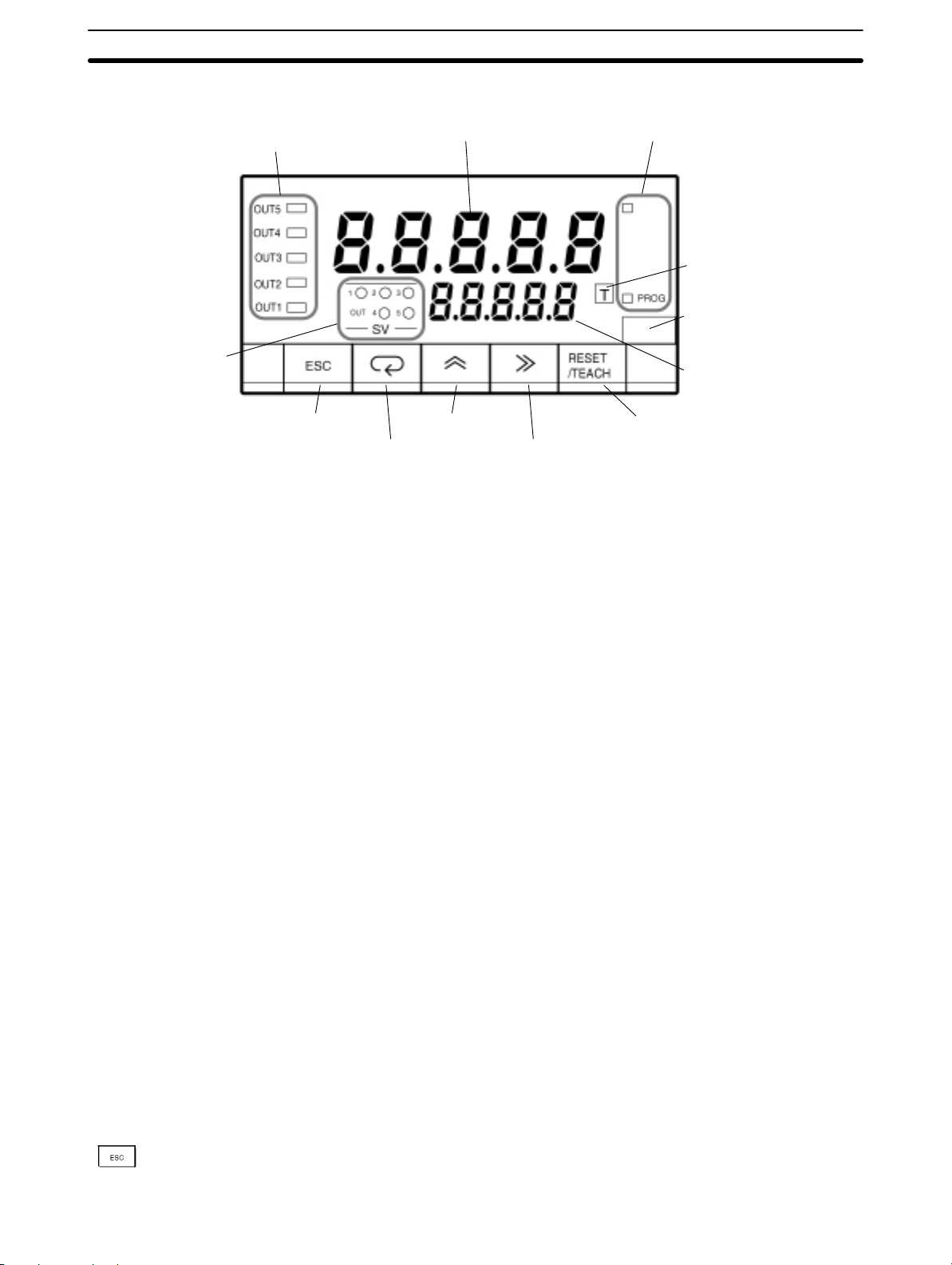
1-2 Front of the Meter
Section 1-2
Comparative output
status indicators
SV display status
indicators
Escape Key
Mode Key
PV display Status indicators
Up Key
Five-digit (–19999 to 99999), seven-segment, 14.2-mm-high LED display with a
programmable decimal point.
The displays show the process value, operations/parameters when setting, and
error messages.
PV Display K3NC-jjjA Basic Model
RUN Mode: Displays the process values. Also displays setting values while
the SV indicator is lit. When changing a value, all digits other
than those that can be set become dimmer.
Setting Mode: Displays the menu, parameter, or setting value. When chang-
ing a value, all digits other than those that can be set become
dimmer.
K3NC-jjjC Set Value LED Display Model
RUN Mode: Displays the process values.
Setting Mode: Displays the menu and parameters.
SV Display (Setting value
LED Display Models Only)
RUN Mode: Displays setting values. When changing a value, all digits other
than those that can be set become dimmer.
Setting Mode: Displays setting values. When changing a value, all digits other
than those that can be set become dimmer.
Comparative Output Status
Indicates the status of the output.
Indicators
RESET
Teaching indicator
Unit of measure
SV display
(SV display models only)
RESET/TEACH Key
Shift Key
Status Indicators RESET Indicator
Lit when the RESET input signal is ON.
PROG Indicator
Lit when the setting mode menu is displayed. The indicator flashes while parameters are displayed.
Teaching Indicator Lit when displayed parameters can be set in teaching operation. The indicator
flashes when the process value is indicated as a setting value.
SV Display Status Indicators Indicates which set value is on the PV or SV display.
Unit of Measure Attach the appropriate label showing the unit of measure (enclosed).
Escape Key
Used to return from the setting, protect, or maintenance mode to the RUN mode.
This key is also used to return to the previous operation during the setting, pro-
tect, or maintenance mode.
3
Page 13
Front of the Meter
Section 1-2
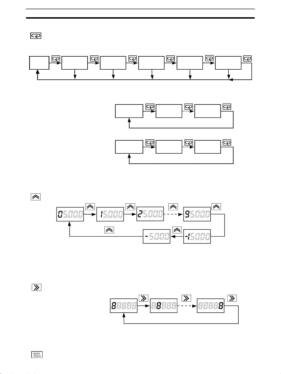
Mode Key
Process
value
OUT1 is lit.
OUT1 setting
value
No key input
for 5 seconds.
Displays a setting value (out of OUT1, 2, 3, 4 and 5 setting values in this order) on
the PV display in RUN mode when this key is pressed. Unless another operation
key is pressed within five seconds after this key has been pressed, the display
automatically changes to the one for process values.
OUT2 is lit. OUT3 is lit. OUT4 is lit.
OUT2 setting
value
No key input
for 5 seconds.
OUT3 setting
value
No key input
for 5 seconds.
OUT4 setting
value
No key input
for 5 seconds.
OUT5 is lit.
OUT5 setting
value
No key input
for 5 seconds.
In the RUN mode, this button terminates the measurement process and allows
you to enter the setting mode, advancing through the menus and parameters.
Menu 1 Menu 2
Parameter 1 Parameter 2 Parameter n
Menu n
Up Key
Shift Key
In the setting mode, this button will store changes in the non-volatile memory
while at the same time advancing the display to the next menu item.
Used to select a parameter to be displayed for setting value change.
Used to increment the current digit in the setting value by one.
The value increases in the following order:
0, 1, 2, 3, 4, 5, 6, 7, 8, 9, (–1), and (–)
Only the leftmost digit will be displayed if the value is set to “–1” or“ –.”
The value will be set to 0 if this key is pressed when “9” or “–” is displayed.
Used to change the parameter displayed in setting mode.
Used to scroll the digit to the right of the presently displayed digit.
RESET/TEACH Key
4
Used to set the counting value forcibly to “0” in RUN mode.
Page 14
Rear of the Meter
Used to select the teaching function. Refer to 5-1 Teaching Function for details.
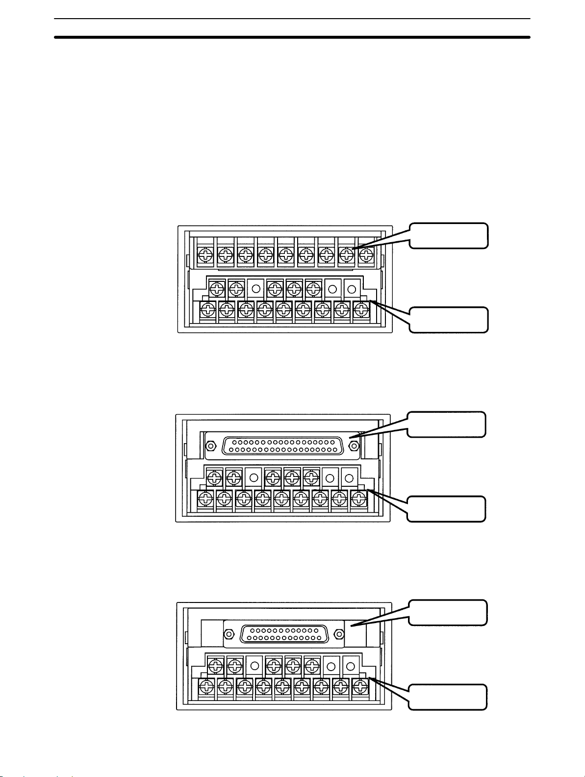
1-3 Rear of the Meter
Terminal arrangement varies depending on the selected Output Board.
For wiring, refer to Section 2 Setup.
K3NC with Relay Output Board, K31-C2, -C5
K3NC with Transistor Output Board, K31-T1, -T2
K3NC with Linear Output Board, K31-L1, -L2, -L3, -L4, -L5, -L6, -L7, -L8, -L9, -L10
K3NC with RS-485 Output Board, K31-FLK2, -FLK5
Section 1-3
Output Board
K3NC with BCD Output Board, K31-B2, -B4
K3NC with RS-232C Output Board, K31-FLK1
Input Board
Output Board
Input Board
Communications
Output Board
Input Board
5
Page 15
Modes
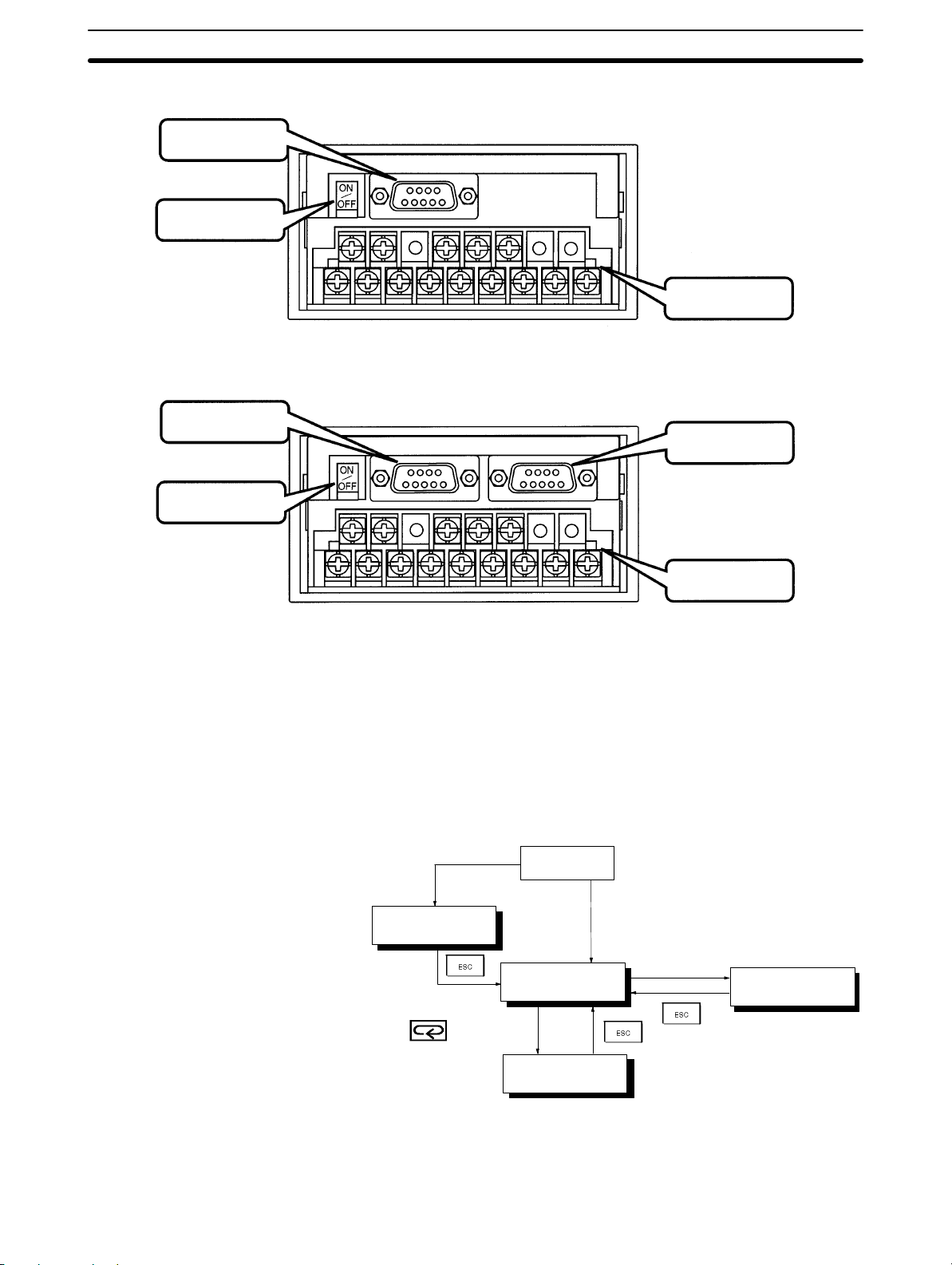
K3NC with RS-422 Output Board, K31-FLK3
Communications
Output Board
Terminator
K3NC with RS232C + Transistor Output Board, K31-FLK4
K3NC with RS-422 + Transistor Output Board, K31-FLK6
Communications
Output Board
Terminator
Section 1-4
Input Board
Transistor
Output Board
1-4 Modes
Input Board
The following four modes are available.
• RUN mode for normal operations (see Section 4 Operations in RUN Mode)
• Setting mode for initializing parameter input (see Section 3 Parameter Setting)
• Protect mode for lock-out configuration (see 3-1 Protect Mode)
• Maintenance mode for initialization (see 5-3-2 Initialization)
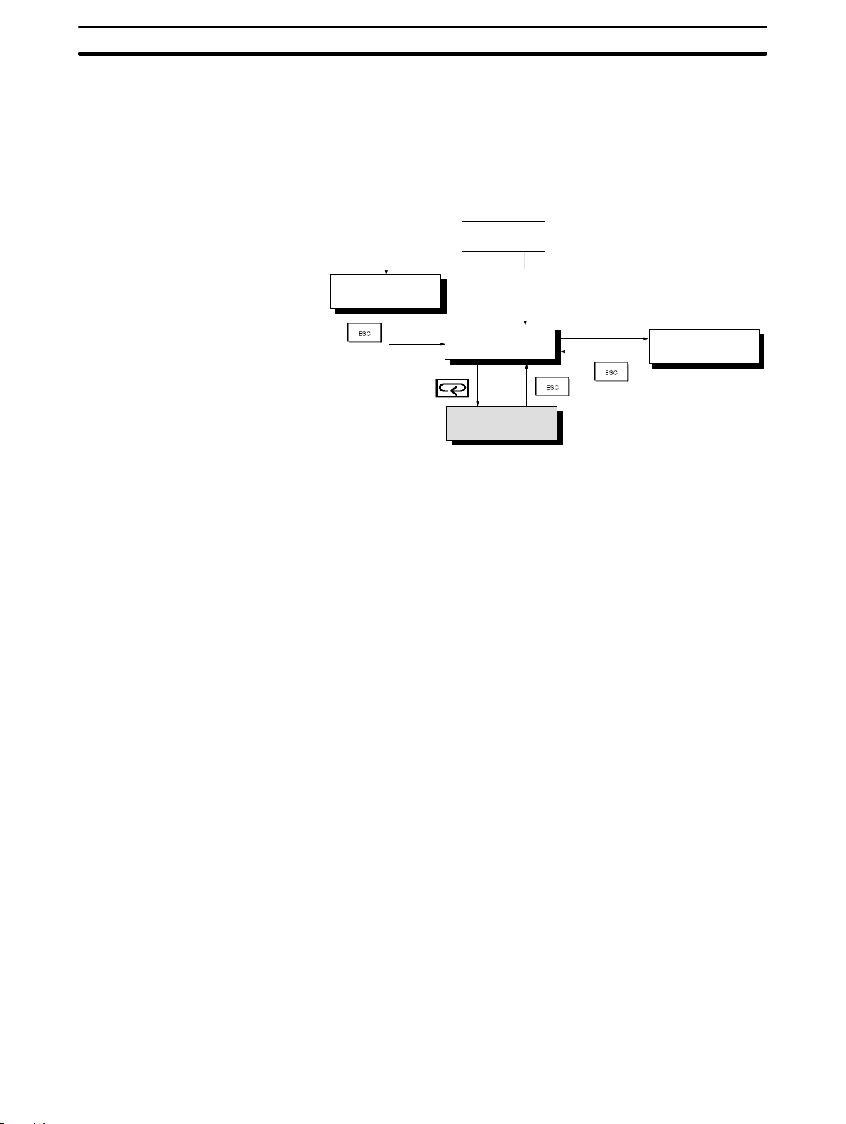
Refer to the following for the relationship among these modes and selection of
the modes.
Press the Mode and Shift Keys
while turning on the K3NC.
Maintenance mode
1 second
Power on
RUN mode
RUN mode
Press the Escape and Up
Keys for 1 second.
Protect mode
Setting mode
RUN Mode K3NC is in RUN when the K3NC is turned ON.
The K3NC in this mode provides an output signal as a result of the comparison of
the measured and setting values.
6
Page 16

Communications Function
The basic model in this mode usually displays the process value. The parameters and setting values are displayed by pressing the Mode Key.
Refer to Section 4 Operations in RUN Mode for RUN mode in detail.
Setting Mode Values are set in the K3NC in this mode by key input or using the teaching func-
tion.
Refer to Section 3 Parameter Setting for value setting by key input and 5-1
Teaching Function for the teaching function in detail.
Protect Mode Use this mode to prohibit some operations in order to lock out the setting values.
Refer to 3-1 Protect Mode for details.
Maintenance Mode The setting values are reset to factory-set values in this mode. Refer to 5-3-2
Initialization for details.
Section 1-5
1-5 Communications Function
The communications function of the K3NC makes it possible for the host computer to perform the following operations.
• Confirmation and change of setting values. Communications conditions cannot be changed.
• Reset of the process value
• Confirmation of model data.
Use a model with the Communications Board if the communications function is
required.
Refer to th e Communications Manual for the communications function in detail.
RS-232C Use the K31-FLK1 or K31-FLK4 Output Board to use the RS-232C interface.
RS-422 Use the K31-FLK3 or K31-FLK6 Output Board to use the RS-422 interface.
RS-485 Use the K31-FLK2 or K31-FLK5 Output Board to use the RS-485 interface.
7
Page 17

This section provides instructions required for mounting and wiring the K3NC.
2-1 Mounting 10. . . . . . . . . . . . . . . . . . . . . . . . . . . . . . . . . . . . . . . . . . . . . . . . . . . . . . . . . . . . . . .
2-2 Input Block 11. . . . . . . . . . . . . . . . . . . . . . . . . . . . . . . . . . . . . . . . . . . . . . . . . . . . . . . . . . . . . .
2-2-1 Terminal Arrangement 11. . . . . . . . . . . . . . . . . . . . . . . . . . . . . . . . . . . . . . . . . . . . . .
2-2-2 Wiring Precautions 12. . . . . . . . . . . . . . . . . . . . . . . . . . . . . . . . . . . . . . . . . . . . . . . . .
2-2-3 Wiring 12. . . . . . . . . . . . . . . . . . . . . . . . . . . . . . . . . . . . . . . . . . . . . . . . . . . . . . . . . .
2-3 Output Board 14. . . . . . . . . . . . . . . . . . . . . . . . . . . . . . . . . . . . . . . . . . . . . . . . . . . . . . . . . . . .
2-3-1 Terminal Arrangement 14. . . . . . . . . . . . . . . . . . . . . . . . . . . . . . . . . . . . . . . . . . . . . .
2-3-2 Relay Output Board 16. . . . . . . . . . . . . . . . . . . . . . . . . . . . . . . . . . . . . . . . . . . . . . . .
2-3-3 Transistor and Combination Output Board 16. . . . . . . . . . . . . . . . . . . . . . . . . . . . . .
2-3-4 Linear Output Board 17. . . . . . . . . . . . . . . . . . . . . . . . . . . . . . . . . . . . . . . . . . . . . . .
2-3-5 BCD Output Board 17. . . . . . . . . . . . . . . . . . . . . . . . . . . . . . . . . . . . . . . . . . . . . . . .
SECTION 2
Setup
9
Page 18
Mounting Section 2-1
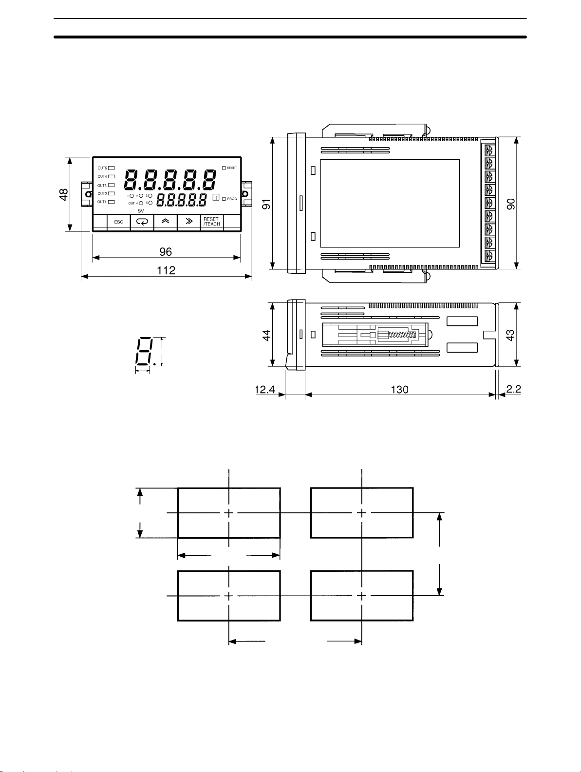
2-1 Mounting
Dimensions All dimensions are in millimeters.
Panel Cutouts
PV LED Indicator Size
14.2 mm
8.2 mm
+0.8
45
–0
92
+0.8
–0
75 min.
10
120 min.
Recommended panel thickness is 1 to 3.2 mm.
Do not mount more than one Unit closely in the horizontal or vertical direction. Be
sure to keep the distance between adjacent Units.
Page 19
Input Block
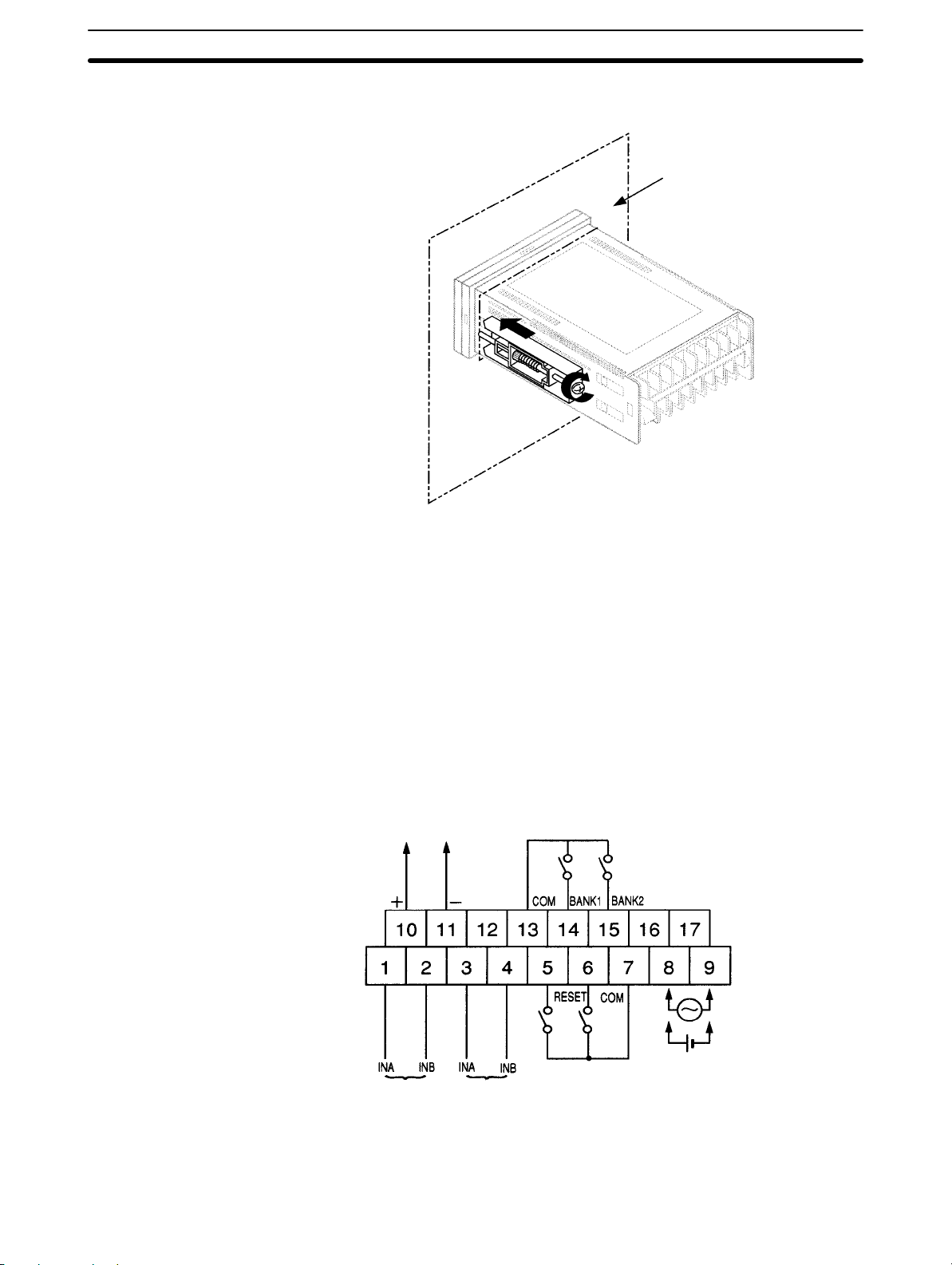
Mounting Method
Section 2-2
Panel
1, 2, 3... 1. Insert the K3NC into the mounting hole on the panel.
2. Hook the fixture claws onto the side holes.
3. Mount a fixing metal to the right and left sides as shown above and while
keeping them in balance, alternately tighten each screw until the ratchet becomes idle.
2-2 Input Block
2-2-1 Terminal Arrangement
Sensor power supply
(80 mA max. at 12 VDC)
100 to 240 to VAC
Open collector
input
Voltage pulse
input
COMPENSATION
Note Voltage pulse input is available for the K3NC-NBjj-jj.
12 to 24 VDC
11
Page 20
Input Block
2-2-2 Wiring Precautions
• Do not make any mistake in polarity when supply DC power to the K3NC.
• Do not wire power lines alongside the signal lines of the K3NC in order to pre-
vent the K3NC from noise interference.
• Wire the terminal block with crimp terminals.
• Tighten each screw to a torque of 0.78 N S m (8 kgf S cm).
2-2-3 Wiring
Power Supply Apply 100 to 240 VAC or 12 to 24 VDC to terminals 8 and 9.
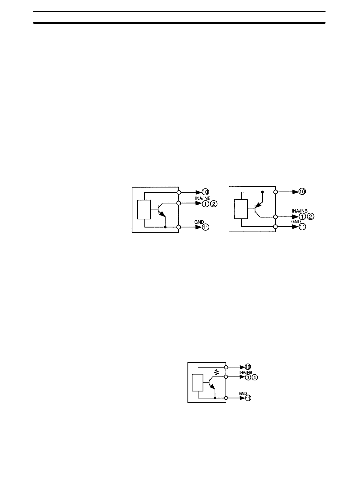
Open Collector Input Connect the pulse output from sensor A to terminal 1.
Connect the pulse output from sensor B to terminal 2.
Terminals 10 and 11 are exclusively used for power supply with an output of
80 mA at 12 VDC to sensors A and B. If power is supplied to the sensors A or B
from a different power source, do not use terminal 10. Do not connect a sensor
with open collector output to terminal 10.
Refer to the following for sensor connections.
Section 2-2
Sensor (with NPN output)
+12 V
• Residual voltage with sensor turned on: 3 V max.
• Current leakage with sensor turned off: 1.5 mA max.
• Switching load current: 20 mA or greater. Must be able to dependable switch
a load current of 5 mA max.
Photoelectric sensors, proximity sensors, rotary encoders, and relays can be
connected as sensors to the K3NC.
Voltage Pulse Input Connect the pulse output of sensor A to terminal 3.
Connect the pulse output of sensor B to terminal 4.
Terminals 10 and 11 are exclusively used for power supply with an output of
80 mA at 12 VDC to sensors A and B. If power is supplied to the sensors A and B
from a different power source, do not use terminal 10. Do not connect a sensor
with voltage pulse output to terminal 10.
Refer to the following for sensor connections.
Sensor (with PNP output)
+12 V
Sensor
H level (sensor output ON): 4.5 to 30 VDC
L level (sensor output OFF): –30 to 2 VDC
Auxiliary Power Supply Terminals 10 and 11 are exclusively used for power supply to sensors with an
output of 80 mA at 12 VDC ± 10%.
+12 V
12
Page 21
Input Block
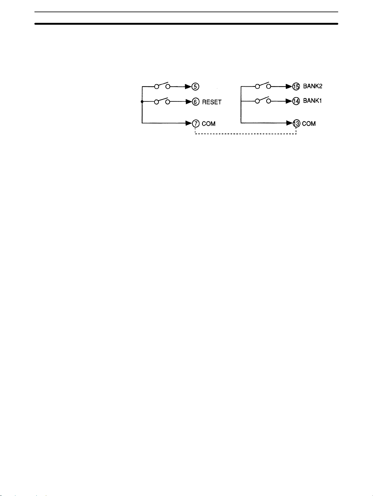
External Signal Input COMPENSATION Input
RESET Input
BANK Input
Connect external signal inputs to terminals 5 through 7 and 13 through 15. Terminals 7 and 13 are connected to each other internally.
Connect COMPENSATION input to terminal 5.
Connect RESET input to terminal 6.
Connect BANK inputs to terminals 14 and 15 for BANK1 and BANK2.
If open collector input is used as external signal input, the transistor must satisfy
the following conditions.
• Residual voltage with transistor turned on: 3 V max.
• Current leakage with transistor turned off: 1.5 mA max.
• Switching load current: 20 mA or greater
Approximately 5 V is imposed between COM and terminals 5 to 7 with a current
flow of approximately 18 mA (a nominal value) at the time of external input shortcircuiting.
Section 2-2
COMPENSATION
Short-circuited together internally.
13
Page 22
Output Board
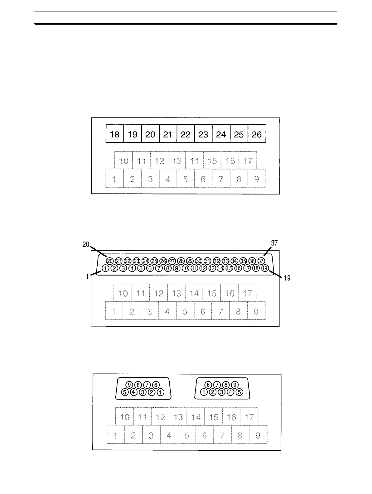
2-3 Output Board
2-3-1 Terminal Arrangement
K3NC with Relay Output Board, K31-C2, -C5
K3NC with Transistor Output Board, K31-T1, -T2
K3NC with Linear Output Board, K31-L1, -L2, -L3, -L4, -L5, -L6, -L7, -L8, -L9, -L10
K3NC with RS-485 Output Board, K31-FLK2, -FLK5
Section 2-3
K3NC with BCD Output Board, K31-B2, -B4
K3NC with RS-232C + Transistor Output Board, K31-FLK4
14
Page 23
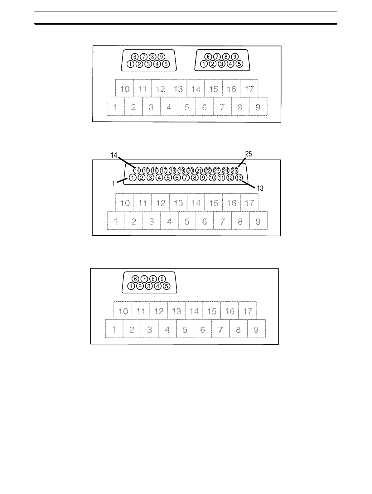
Output Board
K3NC with RS-422 + Transistor Output Board, K31-FLK6
K3NC with RS-232C Output Board, K31-FLK1
Section 2-3
K3NC with RS-422 Output Board, K31-FLK3
15
Page 24
Output Board
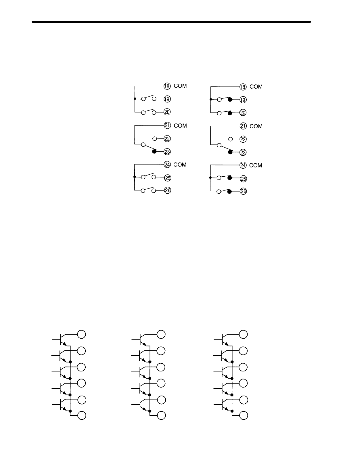
2-3-2 Relay Output Board
The following figures show the connections for relay output.
Section 2-3
K3NC with 5 Relay
Output Boards,
K31-C2
OUT5
OUT4
OUT3
OUT2
OUT1
K3NC with 5 Relay
Output Boards,
K31-C5
The following contact output conditions are required.
5 A (resistive load) at 250 VAC
1.5 A (inductive load) at 250 VAC
5 A (resistive load) at 30 VDC
1.5 A (inductive load) at 30 VDC
OUT5
OUT4
OUT3
OUT2
OUT1
2-3-3 Transistor and Combination Output Board
K3NC with Transistor Output
Board, K31-T1 or K31-T2
K3NC with Linear Output Board,
K31-L4, -L5, -L6, -L9, -L10
K3NC with RS-485 + 5 Relay
Output Boards, K31-FLK5
21
OUT5
22
OUT4
23
OUT3
24
OUT2
25
OUT1
26
COM
K3NC with BCD Output
Board, K31-B2 or K31-B4
32
OUT5
33
OUT4
34
OUT3
35
OUT2
36
OUT1
COM
37
K3NC with RS232C + 5
Transistor Output Boards,
K31-FLK4
K3NC with RS-422 + 5
Transistor Output Boards,
K31-FLK6
1
OUT5
2
OUT4
4
OUT3
5
OUT2
6
OUT1
3
COM
16
Page 25
Output Board
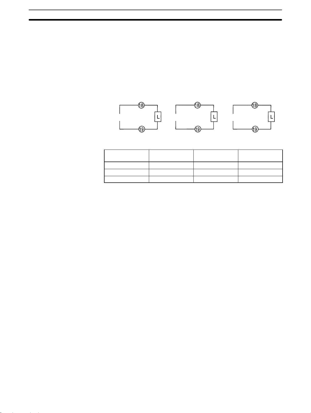
The following transistor output conditions are required.
Maximum rated voltage: 24 VDC
Load current: 50 mA
Current leakage with transistor turned off: 100 µA.
2-3-4 Linear Output Board
The following figures show connections for linear output.
Section 2-3
4 to 20 mA 1 to 5 V
The following linear output conditions are required.
Linear output Permissible load
4 to 20 mA 600 Ω max. 4096 ±0.5% FS
1 to 5 V 500 Ω min. 4096 ±0.5% FS
1 mV/10 digit 1 kΩ min. 4096 ±1.5% FS
2-3-5 BCD Output Board
Refer to Section 6 BCD Output for the terminal arrangement and interface.
K3NC with Linear
Output Board,
K31-L1 or K31-L4
+
–
K3NC with Linear
Output Board,
K31-L2 or K31-L5
resistance
K3NC with Linear
Output Board,
K31-L3 or K31-L6
+
1 mV/10 digit
–
Resolution Output error
+
–
17
Page 26

SECTION 3
Parameter Setting
This section provides instructions for setting the parameters of the K3NC. Be sure to read this section before using the K3NC
Up/Down Counting Meter for the first time.
3-1 Overview 20. . . . . . . . . . . . . . . . . . . . . . . . . . . . . . . . . . . . . . . . . . . . . . . . . . . . . . . . . . . . . . .
3-1-1 Heading Symbols 20. . . . . . . . . . . . . . . . . . . . . . . . . . . . . . . . . . . . . . . . . . . . . . . . . .
3-1-2 Setting Procedures 20. . . . . . . . . . . . . . . . . . . . . . . . . . . . . . . . . . . . . . . . . . . . . . . . .
3-2 Setting Mode 21. . . . . . . . . . . . . . . . . . . . . . . . . . . . . . . . . . . . . . . . . . . . . . . . . . . . . . . . . . . .
3-2-1 Selecting Setting Mode 21. . . . . . . . . . . . . . . . . . . . . . . . . . . . . . . . . . . . . . . . . . . . .
3-2-2 Menu Overview 22. . . . . . . . . . . . . . . . . . . . . . . . . . . . . . . . . . . . . . . . . . . . . . . . . . .
3-2-3 Setting Value Menu (sUset)24. . . . . . . . . . . . . . . . . . . . . . . . . . . . . . . . . . . . . . . . .
Bank No. of Set Value (s.bank)24. . . . . . . . . . . . . . . . . . . . . . . . . . . . . . . . . . . . . . . . . .
OUT1 Set Value (sU*.o1)24. . . . . . . . . . . . . . . . . . . . . . . . . . . . . . . . . . . . . . . . . . . . . . .
OUT2 Set Value (sU*.o2)24. . . . . . . . . . . . . . . . . . . . . . . . . . . . . . . . . . . . . . . . . . . . . . .
OUT3 Set Value (sU*.o3)24. . . . . . . . . . . . . . . . . . . . . . . . . . . . . . . . . . . . . . . . . . . . . . .
OUT4 Set Value (sU*.o4)24. . . . . . . . . . . . . . . . . . . . . . . . . . . . . . . . . . . . . . . . . . . . . . .
OUT5 Set Value (sU*.o5)24. . . . . . . . . . . . . . . . . . . . . . . . . . . . . . . . . . . . . . . . . . . . . . .
3-2-4 Prescaling Menu (pscl)29. . . . . . . . . . . . . . . . . . . . . . . . . . . . . . . . . . . . . . . . . . . .
Prescaling Bank (p.bank)29. . . . . . . . . . . . . . . . . . . . . . . . . . . . . . . . . . . . . . . . . . . . . . .
Prescaling Value X (Mantissa) of Input A (ps*.ax)29. . . . . . . . . . . . . . . . . . . . . . . . . . .
Prescaling Value Y (Exponent) of Input A (ps*.ay)29. . . . . . . . . . . . . . . . . . . . . . . . . .
Decimal Point Position (decp.*)29. . . . . . . . . . . . . . . . . . . . . . . . . . . . . . . . . . . . . . . . .
3-2-5 Setup Menu (setup)32. . . . . . . . . . . . . . . . . . . . . . . . . . . . . . . . . . . . . . . . . . . . . . .
Input Mode (count)32. . . . . . . . . . . . . . . . . . . . . . . . . . . . . . . . . . . . . . . . . . . . . . . . . . .
Sensor Type (in)34. . . . . . . . . . . . . . . . . . . . . . . . . . . . . . . . . . . . . . . . . . . . . . . . . . . . . .
Communications Unit Number (uĆno)36. . . . . . . . . . . . . . . . . . . . . . . . . . . . . . . . . . . . .
Baud Rate (bps)36. . . . . . . . . . . . . . . . . . . . . . . . . . . . . . . . . . . . . . . . . . . . . . . . . . . . . .
Word Length (len)38. . . . . . . . . . . . . . . . . . . . . . . . . . . . . . . . . . . . . . . . . . . . . . . . . . . .
Stop Bits (sbit)38. . . . . . . . . . . . . . . . . . . . . . . . . . . . . . . . . . . . . . . . . . . . . . . . . . . . . .
Parity Bits (prty)38. . . . . . . . . . . . . . . . . . . . . . . . . . . . . . . . . . . . . . . . . . . . . . . . . . . . .
3-2-6 Option Menu (opt)41. . . . . . . . . . . . . . . . . . . . . . . . . . . . . . . . . . . . . . . . . . . . . . . .
Power Failure Memory (memo)41. . . . . . . . . . . . . . . . . . . . . . . . . . . . . . . . . . . . . . . . . . .
Compensation Value (compn)43. . . . . . . . . . . . . . . . . . . . . . . . . . . . . . . . . . . . . . . . . . . .
Compensation Input Condition (comĆp)43. . . . . . . . . . . . . . . . . . . . . . . . . . . . . . . . . . . .
Output Modes (out)45. . . . . . . . . . . . . . . . . . . . . . . . . . . . . . . . . . . . . . . . . . . . . . . . . . .
Upper Limit (H) of Linear Output Range (lset.h)48. . . . . . . . . . . . . . . . . . . . . . . . . . .
Lower Limit (L) of Linear Output Range (lset.l)48. . . . . . . . . . . . . . . . . . . . . . . . . . .
Remote/Local Programming (rĆl)51. . . . . . . . . . . . . . . . . . . . . . . . . . . . . . . . . . . . . . . .
3-3 Protect Mode 53. . . . . . . . . . . . . . . . . . . . . . . . . . . . . . . . . . . . . . . . . . . . . . . . . . . . . . . . . . . .
3-3-1 Selecting Protect Mode 53. . . . . . . . . . . . . . . . . . . . . . . . . . . . . . . . . . . . . . . . . . . . .
3-3-2 Menu Overview 54. . . . . . . . . . . . . . . . . . . . . . . . . . . . . . . . . . . . . . . . . . . . . . . . . . .
3-3-3 Protect Menu (prot)55. . . . . . . . . . . . . . . . . . . . . . . . . . . . . . . . . . . . . . . . . . . . . . .
All Key Protect (all)55. . . . . . . . . . . . . . . . . . . . . . . . . . . . . . . . . . . . . . . . . . . . . . . . . .
Setting Value Change Prohibit (sUset)56. . . . . . . . . . . . . . . . . . . . . . . . . . . . . . . . . . . .
Reset Prohibit (reset)58. . . . . . . . . . . . . . . . . . . . . . . . . . . . . . . . . . . . . . . . . . . . . . . . .
Security (secr)60. . . . . . . . . . . . . . . . . . . . . . . . . . . . . . . . . . . . . . . . . . . . . . . . . . . . . . .
19
Page 27

Overview Section 3-1
3-1 Overview
3-1-1 Heading Symbols
The following symbols are used for headings in this section.
This symbol precedes an explanation of the parameter’s meaning and function.
FUNCTION
This symbol precedes a description of the settings, setting range, and default
value.
SETTING
This symbol precedes an explanation of procedures for parameters that specify
operations.
PROCEDURE
This symbol precedes a listing of references and related parameters.
REFERENCE
This symbol precedes a listing of the models in which this parameter can be
used.
MODELS
3-1-2 Setting Procedures
• The K3NC has four modes: RUN mode for normal operations, Setting mode
for initial parameter input, Protect mode for lock-out configuration, and Maintenance mode for initializing set values. The parameters that are accessible on
any individual K3NC will vary depending on the Output Board installed. Refer
to Appendix D Available Parameters.
• The K3NC is in RUN mode when the K3NC is turned on. Parameter settings in
protect or setting mode are described below on the basis that the parameters
are set for the first time.
For the operation in RUN mode, refer to Section 4 Operations in RUN Mode.
• The setting examples are provided on condition that the factory-set values of
the K3NC have not been changed.
20
Page 28
Setting Mode
3-2 Setting Mode
3-2-1 Selecting Setting Mode
• The K3NC in RUN mode will go into setting mode if the Mode Key is pressed for
1 s minimum.
• The K3NC in setting mode will go into RUN mode if the Escape Key is pressed.
Press the Mode and Shift Keys
while turning the K3NC on.
Section 3-2
Power On
Maintenance mode
1 second
RUN mode
RUN mode
Setting mode
Press the Escape and Up
Keys for 1 second.
Protect mode
• The menu in each mode changes whenever the Mode Key is pressed.
• If the Mode Key is pressed for more than one second while a menu is dis-
played, a parameter will be displayed.
• The parameter changes whenever the Mode Key is pressed.
• If the Shift Key is pressed while a parameter is displayed, the parameter will be
ready to change.
• Press the Up Key to change parameters.
• The digit of a set value is selected with the Shift Key and changed with the Up
Key.
• The PROG indicator is lit while a menu or parameter is displayed.
• The PROG indicator flashes during a set value change.
Note If the input mode is changed, all the other parameters will be set to default val-
ues. Therefore, set the input mode first.
21
Page 29
Setting Mode
Section 3-2
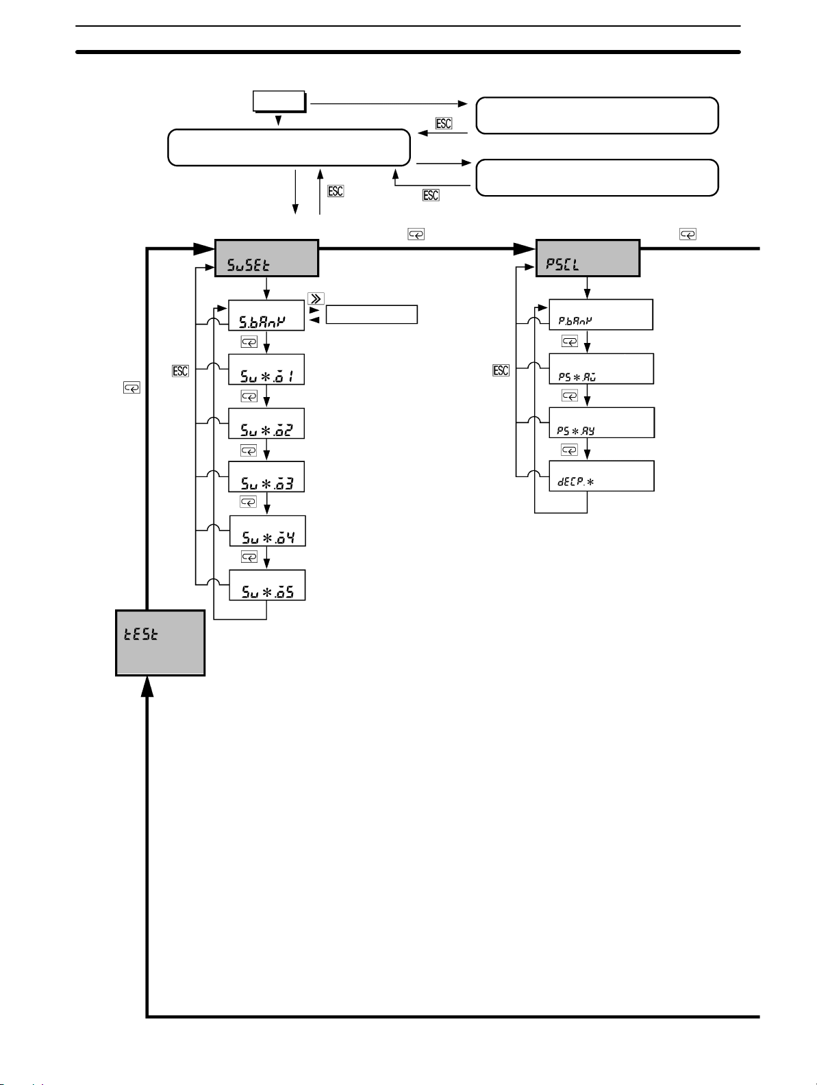
3-2-2 Menu Overview
Power On
RUN Mode
Refer to Section 4 Operations in RUN Mode.
Press the Mode
Key for 1 second.
Setting Mode
Comparative value menu
Bank no. of set
value
OUT1 setting value
OUT2 setting value
OUT3 setting value
Press the Mode and Shift Keys
while turning the K3NC on.
Press the Mode Key for 1 second.
(see note 1)
1 to 4
Note 1:
When making new settings
or changing settings of each
parameter, press the Shift
Key to shift to the setting
state.
The input will be updated
automatically if no change is
made for five seconds
Press the Escape and
Up Keys for 1 second.
Maintenance Mode
Refer to Section 5 Useful Functions.
Protect Mode
Refer to 3-3 Protect Mode.
Prescaling menu
Press the Mode Key for 1 second.
Bank no. of
prescale values
Prescaling value of input A
X (mantissa)
Prescaling value of input A
Y (exponent)
Decimal point
position
Output Test
Refer to Section 5
Useful Functions.
OUT4 setting value
OUT5 setting value
Note: 2
The K3NC stops measurement
in setting mode.
Some menus cannot be set according to the Output Board selected.
If the input mode is changed, all
the other parameters are set to
default values. Therefore, set
the input mode first.
22
Page 30
Setting Mode
Section 3-2
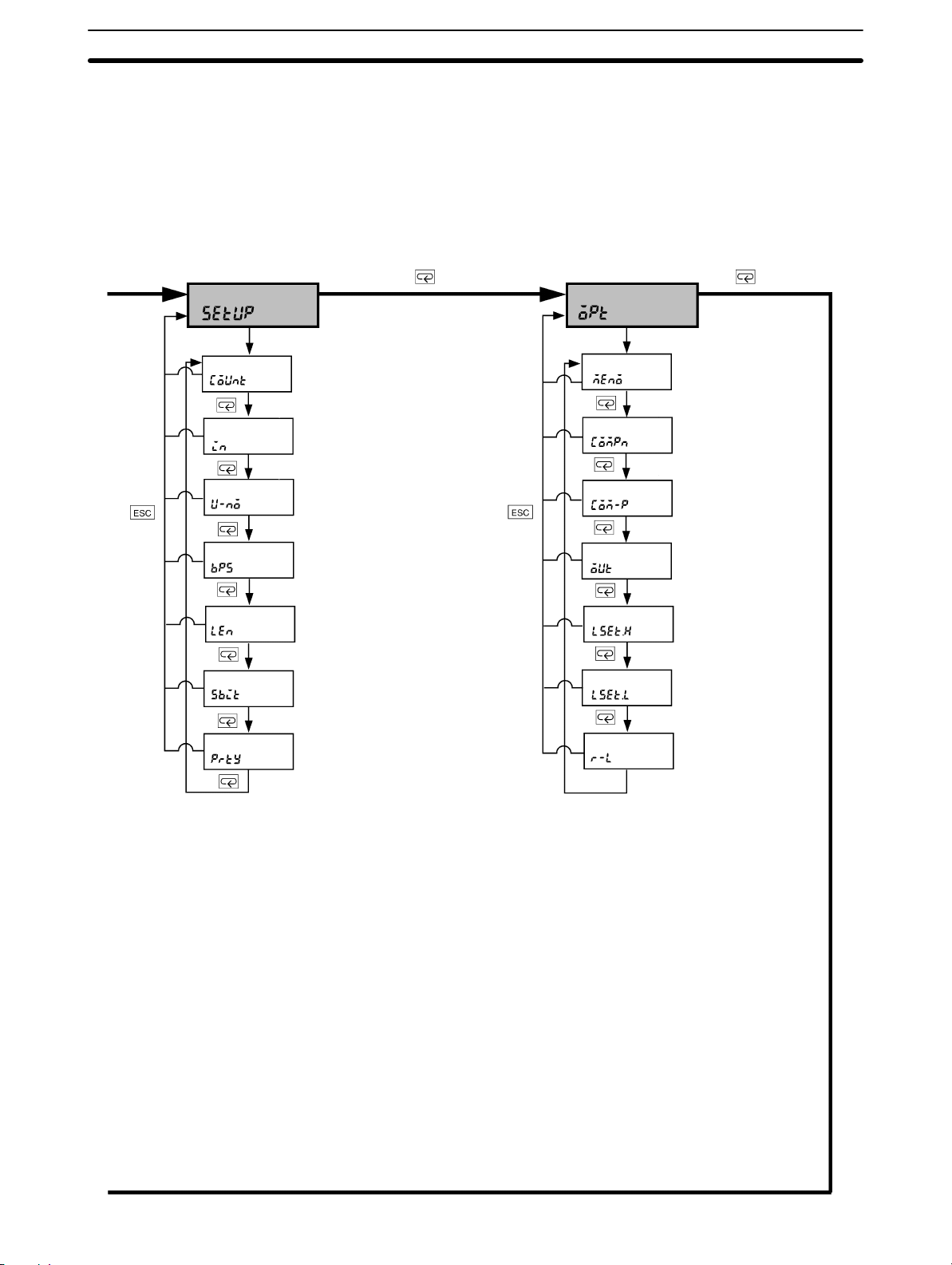
Setup Menu
Input mode
Input sensor type
Communications
unit number
Baud rate
Word length
Stop bits
Parity bits
Press the Mode Key for 1 second.
Option menu
Power failure
memory
Compensation
value
Compensation input condition
Output mode
H linear output
range
L linear output
range
Remote/Local
processing
Press the Mode Key for 1 second.
23
Page 31

Setting Mode
3-2-3 Setting Value Menu (sUset)
Section 3-2
s.bank
sU*.o1
sU*.o2
sU*.o3
sU*.o4
sU*.o5
FUNCTION
Bank No. of Set Value
OUT1 Set Value
OUT2 Set Value
OUT3 Set Value
OUT4 Set Value
OUT5 Set Value
• Sets the set value banks.
• The setting value menu can be used for setting set values OUT1, OUT2,
OUT3, OUT4, and OUT5.
SETTING
REFERENCE
MODELS
Setting Default
Set value bank 1
OUT1 set value 0
OUT2 set value 0
OUT3 set value 0
OUT4 set value 0
OUT5 set value 0
Refer to 5-1 Teaching Function.
• The setting value menu is only available for the K3NC with Comparative Output Board.
24
Page 32

Setting Mode
Section 3-2
SETTING
EXAMPLE
Follow the steps described below to input the following.
Setting value bank = “2”
OUT1 Setting value = “2000”
OUT2 Setting value = “4000”
OUT3 Setting value = “5000”
OUT4 Setting value = “6000”
OUT5 Setting value = “7000”
Set Value LED Display Model Basic Model
RESET RESET
1, 2, 3... 1. Press the Mode Key for more than one second while the sUset setting value
menu is displayed. The s.bank setting value bank setting will be displayed.
Set Value LED Display Model Basic Model
RESET RESET
2. Press the Shift Key to display the set value 1 for changing. The PROG indicator will flash.
Set Value LED Display Model Basic Model
RESET RESET
3. Press the Up Key to set the value to 2. The input will be validated automatically if no change is made for five seconds. The s.bank setting value bank
setting will be displayed again.
Note Press the Mode Key to enter the set value immediately. The sU2.o1
OUT1 setting value of Bank 2 setting will be displayed for setting the
next parameter.
Set Value LED Display Model Basic Model
RESET RESET
4. Press the Mode Key to display the sU2.o1 OUT1 setting value of Bank 2 setting.
Set Value LED Display Model Basic Model
RESET RESET
25
Page 33

Setting Mode
Section 3-2
5. Press the Shift Key to display the set value 0 for changing. The PROG indicator will flash.
Set Value LED Display Model Basic Model
RESET RESET
6. Press the Up and Shift Keys to set the value to 2000. The input will be validated automatically if no change is made for five seconds. The sU2.o1 OUT1
setting value of Bank 2 will be displayed again.
Note Press the Mode Key to enter the set value immediately. The sU2.o2
OUT2 setting value of Bank 2 will be displayed for setting the next parameter.
Set Value LED Display Model Basic Model
RESET RESET
7. Press the Mode Key to display the sU2.o2 OUT2 setting value of Bank 2 setting.
Set Value LED Display Model Basic Model
RESET RESET
8. Press the Shift Key to display the set value 0 for changing. The PROG indicator will flash.
Set Value LED Display Model Basic Model
RESET RESET
9. Press the Up and Shift Keys to set the value to 4000. The input will be validated automatically if no change is made for five seconds. The sU2.o2 OUT2
setting value of Bank 2 setting will be displayed again.
Note Press the Mode Key to enter the set value immediately. The sU2.o3
OUT3 setting value of Bank 2 setting will be displayed for setting the
next parameter.
Set Value LED Display Model Basic Model
RESET RESET
10. Press the Mode Key to display the sU2.o3 OUT3 setting value of Bank 3
OUT3 setting.
Set Value LED Display Model Basic Model
RESET RESET
26
Page 34

Setting Mode
Section 3-2
11. Press the Shift Key to display the set value 0 for changing. The PROG indicator will flash.
Set Value LED Display Model Basic Model
RESET RESET
12. Press the Up and Shift Keys to set the value to 5000. The input will be vali-
dated automatically if no change is made for five seconds. The sU2.o3 OUT3
setting value of Bank 2 setting will be displayed again.
Note Press the Mode Key to enter the input immediately. The sU2.o4 OUT4
setting value of Bank 2 setting will be displayed for setting the next
parameter.
Set Value LED Display Model Basic Model
RESET RESET
13. Press the Mode Key to display the sU2.o4 OUT4 setting value of Bank 2 setting.
Set Value LED Display Model Basic Model
RESET RESET
14. Press the Shift Key to display the set value 0 for changing. The PROG indicator will flash.
Set Value LED Display Model Basic Model
RESET RESET
15. Press the Up and Shift Keys to set the value to 6000. The input will be vali-
dated automatically if no change is made for five seconds. The sU2.o4 OUT4
setting value of Bank 2 setting will be displayed again.
Note Press the Mode Key to enter the set value immediately. The sU2.o5
OUT5 setting value of Bank 2 setting will be displayed for setting the
next parameter.
Set Value LED Display Model Basic Model
RESET RESET
16. Press the Mode Key to display the sU2.o5 OUT5 setting value of Bank 2 setting.
Set Value LED Display Model Basic Model
RESET RESET
27
Page 35

Setting Mode
Section 3-2
17. Press the Shift Key to display the set value 0 for changing. The PROG indicator will flash.
Set Value LED Display Model Basic Model
RESET RESET
18. Press the Up and Shift Keys to set the value to 7000. The input will be vali-
dated automatically if no change is made for five seconds. The sU2.o5 OUT5
setting value of Bank 2 setting will be displayed again.
Set Value LED Display Model Basic Model
RESET RESET
19. Press the Escape Key to display the sUset setting value menu.
Set Value LED Display Model Basic Model
RESET RESET
28
Page 36

Setting Mode
3-2-4 Prescaling Menu (pscl)
Section 3-2
p.bank
ps*.ax
ps*.ay
decp.*
FUNCTION
Prescaling Bank
Prescaling Value X (Mantissa) of Input A
Prescaling Value Y (Exponent) of Input A
Decimal Point Position
The measured data is displayed after being multiplied by a preset value (i.e.,
prescaling value).
Display value = Measured data x prescaling value
Input type Setting Default
p.bank: Prescaling bank off/1 to 4 off
ps*.ax: Prescaling value X (mantissa)
of input A
ps*.ay: Prescaling value Y (exponent)
of input A
decp.*: Decimal point position
0.0001 to 9.9999 1.0000
–9 to 9 0
One of the 1st to 4th digits
from the right
No decimal
point
position
setting
SETTING
EXAMPLE
Follow the steps described below to input the following.
Prescaling bank = 1
Prescaling value X (mantissa) of input A = 0.5000
Prescaling value Y (exponent) of input A = –1
Decimal point = jjjj.j
Set Value LED Display Model Basic Model
RESET RESET
1, 2, 3... 1. Press the Mode Key for more than one second while the pscl prescaling
menu is displayed. The p.bank prescaling bank setting will be displayed.
Set Value LED Display Model Basic Model
RESET RESET
2. Press the Shift Key to display off for changing. The PROG indicator will
flash.
Set Value LED Display Model Basic Model
RESET RESET
29
Page 37

Setting Mode
Section 3-2
3. Press the Up Key to change the prescaling bank setting. The input will be
validated automatically if no change is made for five seconds. The p.bank
prescaling bank setting will be displayed again.
Note Press the Mode Key to enter the set value immediately. The ps.ax
prescaling value X (mantissa) of input A setting will be displayed for
setting the next parameter.
Set Value LED Display Model Basic Model
RESET RESET
4. Press the Mode Key to display the ps.ax prescaling value X (mantissa) of
input A setting.
Set Value LED Display Model Basic Model
RESET RESET
5. Press the Shift Key to display the set value 1.0000 for changing. The PROG
indicator will flash.
Set Value LED Display Model Basic Model
RESET RESET
6. Press the Up and Shift Keys to set the value to 0.5000. The input will be validated automatically if no change is made for five seconds. The ps.ax prescaling value X (mantissa) of input A setting will be displayed again.
Note Press the Mode Key to enter the set value immediately. The ps.ax
prescaling value X (mantissa) of input A setting will be displayed for
setting the next parameter.
Set Value LED Display Model Basic Model
RESET RESET
7. Press the Mode Key to display the ps.ay prescaling value Y (exponent) of
input A setting.
Set Value LED Display Model Basic Model
RESET RESET
30
8. Press the Shift Key to display the set value 10 00 for changing.
Set Value LED Display Model Basic Model
RESET RESET
Page 38

Setting Mode
Section 3-2
9. Press the Up and Shift Keys to set the value to 10 Ć1. The input will be validated automatically if no change is made for five seconds. The ps.ay prescaling value Y (exponent) of input A setting will be displayed again.
Note Press the Mode Key to enter the set value immediately. The decp
decimal point position setting will be displayed for setting the next pa rameter.
Set Value LED Display Model Basic Model
RESET RESET
10. Press the Mode Key to display the decp.1 decimal point position setting.
Set Value LED Display Model Basic Model
RESET RESET
11. Press the Shift Key to display %%%%% for changing.
Set Value LED Display Model Basic Model
RESET RESET
12. Press the Shift Key to set %%%%.%. The input will be validated automatically if
no change is made for five seconds. The decp.1 decimal point position setting will be displayed again.
Note Press the Mode Key to enter the set value immediately. The p.bank
prescaling bank setting will be displayed for setting the next parameter.
Set Value LED Display Model Basic Model
RESET RESET
When no operation is executed for five seconds
Set Value LED Display Model Basic Model
RESET RESET
13. Press the Escape Key to display the pscl prescaling menu.
Set Value LED Display Model Basic Model
RESET RESET
31
Page 39

Setting Mode
3-2-5 Setup Menu (setup)
Section 3-2
count
FUNCTION
Input Mode
• All parameters will be set to default values if any change in made in this menu.
• Selects the individual or phase-difference input.
The counting mode can be set to either individual input or phase-difference input. Pulses of up to 50 kHz can be input. The minimum pulse width is 9 µs for
both the ON and OFF sides.
Individual Inputs
This input mode counts by using input A as the increment input and input B as
the decrement input. The count is incremented at the rising edge of input A and
decremented at the rising edge of input B. The count is left unchanged if the inputs are simultaneous.
Input A
Input B
SETTING
Count
Phase-difference Inputs
This input mode increments the count when input A precedes input B and decrements the count when input B precedes input A. The count is incremented at the
rising edge of input B and decremented at the rising edge of input A.
Input A
Input B
Count
Setting Default
uĆd b: Individual input
uĆd c: Phase-difference input
uĆd c
32
Page 40

Setting Mode
Section 3-2
SETTING
EXAMPLE
Follow the steps described below to select the uĆd b individual input setting.
Set Value LED Display Model Basic Model
RESET RESET
1, 2, 3... 1. Press the Mode Key for more than one second while the setup setup menu
is displayed. The count input mode setting will appear.
Set Value LED Display Model Basic Model
RESET RESET
2. Press the Shift Key to display the set value uĆd c for changing. The PROG
indicator will flash.
Set Value LED Display Model Basic Model
RESET RESET
3. Repeatedly press the Up Key until uĆd b is displayed. The displayed setting
will be validated automatically if no change is made for five seconds. The
count counting mode setting will be displayed again.
Note Press the Mode Key to enter the displayed setting immediately. The
next parameter will be displayed for setting.
Set Value LED Display Model Basic Model
\
RESET RESET
When no operation is executed for five seconds
Set Value LED Display Model Basic Model
RESET RESET
4. Repeatedly press the Escape Key until the setup setup menu is displayed.
33
Page 41

Setting Mode
Section 3-2
in
FUNCTION
SETTING
Sensor Type
• Specifies the type of sensors for input A and input B.
• Open Collector Input
Transistor input
Relay input
Normally Open Model: The sensor output is OFF (open) when the sensor is
Normally Closed Model:The sensor output is ON (closed) when the sensor is
• Voltage Pulse Input
Voltage pulse input
Sensor type Normally open Normally closed Default
00 01
10 11
00
not sensing an object.
not sensing an object.
Sensor type Normally open Normally closed Default
10 11 00
SETTING
EXAMPLE
Follow the steps described below to set the sensor type to 11 when setting uĆd b (individual input) of count (input mode).
Set Value LED Display Model Basic Model
RESET RESET
1, 2, 3... 1. Press the Mode Key for more than one second while the setup setup menu
is displayed. The count input mode setting will appear.
Set Value LED Display Model Basic Model
RESET RESET
2. Press the Mode Key to display in sensor type setting.
Set Value LED Display Model Basic Model
RESET RESET
3. Press the Shift Key to display 00 for changing. The PROG indicator will flash.
34
Set Value LED Display Model Basic Model
RESET RESET
Page 42

Setting Mode
Section 3-2
4. Press the Up and Shift Keys to display 11. The displayed setting will be validated automatically if no change is made for five seconds. The in sensor
type setting will be displayed again.
Note Press the Mode Key to enter the displayed setting immediately. The
next parameter will be displayed.
Set Value LED Display Model Basic Model
RESET RESET
5. Press the Escape Key to display the setup setup menu.
Set Value LED Display Model Basic Model
RESET RESET
35
Page 43

Setting Mode
Section 3-2
uĆno
bps
FUNCTION
SETTING
Communications Unit Number
Baud Rate
• Set a communications unit number as an identification number by which the
host computer is connected to the K3NC.
• If more than one K3NC is connected in parallel, make sure that each communications unit number is unique.
• The baud rate should be set to the baud rate of the host computer.
• Communications Unit Number
Setting range Unit Default
00 to 99 --- 00
• Baud Rate
Setting range Default
1200: 1,200 bps / 2400: 2,400 bps / 4800: 4,800 bps /
9600: 9,600 bps / 19200:19.2 Kbps / 38400: 38.4 Kbps
9600
MODELS
SETTING
EXAMPLE
This setting is available for the K3NC with the Communications Output Board.
Follow the steps described below to set the communications unit number to 15 and the
baud rate to 19,200 bps.
Set Value LED Display Model Basic Model
RESET RESET
1, 2, 3... 1. Press the Mode Key for more than one second while the setup setup menu
is displayed. The count input mode setting will appear.
Set Value LED Display Model Basic Model
RESET RESET
2. Repeatedly press the Mode Key until the uĆno communications unit number
setting is displayed.
36
Set Value LED Display Model Basic Model
RESET RESET
Page 44

Setting Mode
Section 3-2
3. Press the Shift Key to display the prior set value 00 for changing. The PROG
indicator will flash.
Set Value LED Display Model Basic Model
RESET RESET
4. Press the Up and Shift Keys to set the value to 15. The input value will be
validated automatically if no change is made for five seconds. The uĆno
communications unit number setting will be displayed again.
Note Press the Mode Key to enter the set value immediately. The next pa-
rameter will be displayed for setting.
Set Value LED Display Model Basic Model
RESET RESET
5. Press the Mode Key to display the bps baud rate setting.
Set Value LED Display Model Basic Model
RESET RESET
6. Press the Shift Key to display the prior set value 9600 for changing. The
PROG indicator will flash.
Set Value LED Display Model Basic Model
RESET RESET
7. Press the Up Key to set the value to 19200. The input will be validated automatically if no change is made for five seconds. The bps baud rate setting
will be displayed again.
Note Press the Mode Key to enter the set value immediately. The next pa-
rameter will be displayed again for setting.
Set Value LED Display Model Basic Model
RESET RESET
8. Press the Up Key to enter the set value for setting the next parameter. The
input value will be validated automatically if no change is made for five seconds. The bps baud rate setting will be displayed again.
Set Value LED Display Model Basic Model
RESET RESET
37
Page 45

Setting Mode
Section 3-2
len
sbit
prty
FUNCTION
SETTING
Word Length
Stop Bits
Parity Bits
• The communications format used for communicating with the host computer is
set in the setup menu.
• Refer to the Communications Manual for the communications format in detail.
• Word Length
7/8 bit 7
• Stop Bits
1/2 bit 2
• Parity Bit
none: None
eUen: Even
odd: Odd
Setting Unit Default
Setting Unit Default
Setting Default
eUen
MODELS
SETTING
EXAMPLE
This setting is available for the K3NC with the Communications Output Board.
Follow the steps described below to set the following.
Word length: 8 bits
Number of stop bits: 1
Parity bits: none
Set Value LED Display Model Basic Model
RESET RESET
1, 2, 3... 1. Press the Mode Key for more than one second while the setup setup menu
is displayed. The count counting mode setting will appear.
Set Value LED Display Model Basic Model
RESET RESET
2. Repeatedly press the Mode Key until the len word length setting is displayed.
Set Value LED Display Model Basic Model
RESET RESET
38
Page 46

Setting Mode
Section 3-2
3. Press the Shift Key to display the prior set value 7 for changing. The PROG
indicator will flash.
Set Value LED Display Model Basic Model
RESET RESET
4. Press the Up Key to set the value to 8. The input value will be validated automatically if no change is made for five seconds. The len word length setting
will be displayed again.
Note Press the Mode Key to enter the set value immediately. The next pa-
rameter will be displayed for setting.
Set Value LED Display Model Basic Model
RESET RESET
5. Press the Mode Key to display the sbit stop bit setting.
Set Value LED Display Model Basic Model
RESET RESET
6. Press the Shift Key to display the set value 2 for changing.
Set Value LED Display Model Basic Model
RESET RESET
7. Press the Up Key to set the value to 1. The input will be validated automatically if no change is made for five seconds. The sbit stop bit setting will be
displayed again.
Note Press the Mode Key to enter the set value immediately. The next pa-
rameter will be displayed for setting.
Set Value LED Display Model Basic Model
RESET RESET
8. Press the Mode Key to display the prty parity bit setting.
Set Value LED Display Model Basic Model
RESET RESET
39
Page 47

Setting Mode
Section 3-2
9. Press the Shift Key to display eUen for changing.
Set Value LED Display Model Basic Model
RESET RESET
10. Press the Up Key to display none. The setting will be validated automatically
if no change is made for five seconds. The prty parity bit setting will be displayed again.
Note Press the Mode Key to enter the setting immediately. The next pa-
rameter will be displayed for setting.
Set Value LED Display Model Basic Model
RESET RESET
When no operation is executed for five seconds
Set Value LED Display Model Basic Model
RESET RESET
40
Page 48

Setting Mode
3-2-6 Option Menu (opt)
Section 3-2
memo
FUNCTION
SETTING
SETTING
EXAMPLE
Power Failure Memory
Keeps the process value at the time of power failure.
Setting Default
on: Stored
off: Not stored
Follow the steps described below to set on to enable power failure memory.
off
Set Value LED Display Model Basic Model
RESET RESET
1, 2, 3... 1. Press the Mode Key for more than one second while the opt option menu is
displayed. The memo power failure memory setting will appear.
Set Value LED Display Model Basic Model
RESET RESET
2. Press the Shift Key to display the set data off for changing. The PROG indicator will flash.
Set Value LED Display Model Basic Model
RESET RESET
3. Press the Up Key to display on. The displayed setting will be validated automatically if no change is made for five seconds. The memo power failure
backup memory setting will be displayed again.
Note Press the Mode Key to enter the displayed setting immediately. The
next parameter will be displayed for setting.
Set Value LED Display Model Basic Model
RESET RESET
41
Page 49

Setting Mode
Section 3-2
When no operation is executed for five seconds
Set Value LED Display Model Basic Model
RESET RESET
4. Press the Escape Key to display the opt option menu.
Set Value LED Display Model Basic Model
RESET RESET
42
Page 50

Setting Mode
d Compensation Value
compn
Section 3-2
comĆp
FUNCTION
SETTING
Compensation Input Condition
• The value set in this menu is used as the compensation value of the K3NC. The
present value is forcibly reset to the compensation value if the COMPENSATION input is ON, and the counting operation of the K3NC begins with the compensation value.
• The conditions can be sent for when the compensation function is to be enabled. The compensation function is always enabled (i.e., enabled during both
incrementation and decrementation) when set to all ; it is enabled only during
incrementation when set to plus.
Setting Default
Compensation value
Condition setting
Refer to 4-2 External Input Signals.
–19999 to 99,999
all: Incrementing and
decrementing
plus: Incrementing only
00000
all
REFERENCE
SETTING
EXAMPLE
Follow the steps described below to set the compensation value to 70.
Set the compensation input condition to plus.
Set Value LED Display Model Basic Model
RESET RESET
1, 2, 3... 1. Press the Mode Key for more than one second while the opt option menu is
displayed. The memo power failure memory setting will appear.
Set Value LED Display Model Basic Model
RESET RESET
2. Repeatedly press the Mode Key until the compn compensation value setting
is displayed.
Set Value LED Display Model Basic Model
RESET RESET
43
Page 51

Setting Mode
Section 3-2
3. Press the Shift Key to display the set value 00000 for changing. The PROG
indicator will flash.
Set Value LED Display Model Basic Model
RESET RESET
4. Press the Up and Shift Keys to set the value to 70. The input will be validated
automatically if no change is made for five seconds. The compn compensation value setting will be displayed again.
Set Value LED Display Model Basic Model
RESET RESET
5. Press the Mode Key to display the comĆp compensation input condition setting.
Set Value LED Display Model Basic Model
RESET RESET
6. Press the Shift Key to display all for changing. The PROG indicator will
flash.
Set Value LED Display Model Basic Model
RESET RESET
7. Press the Up Key to display plus. The input will be validated automatically if
no change is made for five seconds. The comĆp compensation input condition setting will be displayed again.
Note Press the Mode Key to enter the set value immediately. The next pa-
rameter will be displayed for setting.
Set Value LED Display Model Basic Model
RESET RESET
44
When no operation is executed for five seconds
Set Value LED Display Model Basic Model
RESET RESET
Page 52

Setting Mode
Section 3-2
out
FUNCTION
Output Modes
Specifies the output mode of the comparative outputs OUT1, OUT2, OUT3,
OUT4, or OUT5.
The K3NC is equipped with two output modes, ALL-H mode and ALL-L mode.
The measured value is compared to set values 1 through 5 and the corresponding output (1 through 5) is turned ON if the measured value is above (ALL-H
mode) or below (ALL-L mode) the set value.
ALL-H Mode
If ALL-H output mode is selected, outputs 1 to 5 will be ON when the measured
value exceeds set values 1 to 5.
Set value 5
Set value 4
Set value 3
Set value 2
Set value 1
Compensation
Measured value
See note
1
Reset
signal
Output 5
Output 4
Output 3
Output 2
Output 1
45
Page 53

Setting Mode
Section 3-2
ALL-L Mode
If ALL-L output mode is selected, outputs 1 to 5 will be ON when the measured
value is less than set values 1 to 5.
Set value 5
Set value 4
Set value 3
Set value 2
Set value 1
Reset
(see note 2)
Compensation
signal
(see note 2)
Output 5
Output 4
Output 3
Output 2
Output 1
Measured value
Note 1. Set value 2 < compensation value < set value 3
2. Reset and Compensation Signals:
While the reset signal is ON, the counting value will return to zero.
When the compensation signal is ON, the K3NC will be in counting operation starting with the preset compensation value. By selecting plus in com-
pensation value parameter , the compensation value will be ef fective only for
the adding operation.
See note
1
SETTING
MODELS
SETTING
EXAMPLE
Setting Default
allĆh: Outputs 1 to 5 ON when the PV ≥ SV 1 to 5.
allĆh
allĆl: Outputs 1 to 5 ON when the PV ≤ SV 1 to 5.
This mode is only available for the K3NC with the Comparative Output Board.
Follow the steps described below to set the allĆl ALL-L output mode.
Set Value LED Display Model Basic Model
RESET RESET
1, 2, 3... 1. Press the Mode Key for more than one second while the opt option menu is
displayed. The memo power failure memory setting will appear.
Set Value LED Display Model Basic Model
RESET RESET
46
Page 54

Setting Mode
Section 3-2
2. Repeatedly press the Mode Key until the out output mode setting is displayed.
Set Value LED Display Model Basic Model
RESET RESET
3. Press the Shift Key to display allĆh for changing. The PROG indicator will
flash.
Set Value LED Display Model Basic Model
RESET RESET
4. Press the Up Key to set the value to allĆl. The input will be validated automatically if n o change is made for five seconds. The out output mode setting
will be displayed again.
Note Press the Mode Key to enter the displayed setting immediately. The
next parameter will be displayed for setting.
Set Value LED Display Model Basic Model
RESET RESET
When no operation is executed for five seconds
Set Value LED Display Model Basic Model
RESET RESET
47
Page 55

Setting Mode
Section 3-2
lset.h
lset.l
FUNCTION
Upper Limit (H) of Linear Output Range
Lower Limit (L) of Linear Output Range
Linear output setting is made in the option menu to enable the K3NC to have
voltage or current output in proportion to the change in display value.
• The maximum and minimum values of linear output are set in this parameter.
Linear output
20 mA or 5 V
4 mA or 1 V
Display value
• L can be greater or less than H.
• L cannot be the same as H, otherwise H will be automatically set to a value
obtained by adding 1 to L.
• The teaching function can be used for setting linear output ranges.
SETTING
REFERENCE
MODELS
Setting range Default
–19999 to 99999
Refer to 5-1 Teaching Function.
This setting is available for the K3NC with the Linear Output Board.
H linear output range
L linear output range –19999
99999
48
Page 56

Setting Mode
Section 3-2
SETTING
EXAMPLE
Follow the steps described below to set the following. (Assume that the decimal point is
set between the second and third digits from the right in the prescale menu.)
H: 100.00
L: 0.00
Set Value LED Display Model Basic Model
RESET RESET
1, 2, 3... 1. Press the Mode Key for more than one second while the opt option menu is
displayed. The memo power failure memory setting will appear.
Set Value LED Display Model Basic Model
RESET RESET
2. Repeatedly press the Mode Key until the lset.h H linear output range set-
ting is displayed.
Set Value LED Display Model Basic Model
RESET RESET
3. Press the Shift Key to display the prior set value 999.99 for changing. The
PROG indicator will flash.
Set Value LED Display Model Basic Model
RESET RESET
4. Press the Up and Shift Keys to set the value to 100.00. The setting will be
validated automatically if no change is made for five seconds. The lset.h H
linear output range setting will be displayed again.
Note Press the Mode Key to enter the set value immediately. The next pa-
rameter will be displayed for setting.
Set Value LED Display Model Basic Model
+
RESET RESET
5. Press the Mode Key to display the lset.l L linear output range setting.
Set Value LED Display Model Basic Model
RESET RESET
49
Page 57

Setting Mode
Section 3-2
6. Press the Shift Key to display the prior set value Ć199.99 for changing. The
PROG indicator will flash.
Set Value LED Display Model Basic Model
RESET RESET
7. Press the Up and Shift Keys to set the value to 000.00. The setting will be
validated automatically if no change is made for five seconds. The lset.l L
linear output range setting will be displayed again.
Note Press the Mode Key to enter the set value immediately. The next pa-
rameter will be displayed for setting.
Set Value LED Display Model Basic Model
RESET RESET
When no operation is executed for five seconds
Set Value LED Display Model Basic Model
RESET RESET
50
Page 58

Setting Mode
Section 3-2
rĆl
FUNCTION
SETTING
MODELS
SETTING
EXAMPLE
Remote/Local Programming
• The K3NC can be set to remote or local mode in the option menu. The K3NC in
remote mode is operated through the host computer and the K3NC in local
mode is operated through the front panel key input.
Setting Default
Remote: rmt
Local: lcl
This setting is available for the K3NC with the Communications Output Board.
Follow the steps described below to set the K3NC to remote programming.
Set Value LED Display Model Basic Model
lcl
RESET RESET
1, 2, 3... 1. Press the Mode Key for more than one second while the opt option menu is
displayed. The memo power failure memory setting will appear.
Set Value LED Display Model Basic Model
RESET RESET
2. Repeatedly press the Mode Key until the rĆl remote/local setting is displayed.
Set Value LED Display Model Basic Model
RESET RESET
3. Press the Shift Key to display the prior setting lcl for changing. The PROG
indicator will flash.
Set Value LED Display Model Basic Model
RESET RESET
4. Press the Up Key to display rmt.
Set Value LED Display Model Basic Model
RESET RESET
51
Page 59

Setting Mode
Section 3-2
5. The setting will be validated automatically if no change is made for five seconds. The memo power failure memory setting will appear.
Note Press the Mode Key to enter the setting immediately. The rĆl re-
mote/local setting will be displayed again.
Set Value LED Display Model Basic Model
RESET RESET
52
Page 60

Protect Mode
3-3 Protect Mode
3-3-1 Selecting Protect Mode
• The K3NC in RUN mode will go into protect mode if the Escape and Up Keys
are pressed for more than 1 second.
• The K3NC in protect mode will go into RUN mode if the Escape Key is pressed.
Press the Mode and Shift Keys
while turning the K3NC on.
Section 3-3
Power On
Maintenance mode
RUN mode
1 second
Setting mode
Press the Escape and Up
Keys for 1 second.
Protect mode
• If the Mode Key is pressed for more than one second while a menu is displayed, a parameter will be displayed.
• The parameter changes whenever the Mode Key is pressed.
• If the Shift Key is pressed while a parameter is displayed, the parameter will be
ready to change.
• Press the Up Key to change parameters.
53
Page 61

Protect Mode
3-3-2 Menu Overview
Section 3-3
Press the Mode and Shift Keys
Power On
while turning the K3NC on.
RUN Mode
Refer to Section 4 Operations in RUN Mode.
Press the Escape and
Up Keys for 1 second.
Protect Mode
Protect menu
All key protect
No key input
for 5 seconds.
Setting value
change prohibit
No key input
for 5 seconds.
Press the Mode Key
for 1 second.
Key protect ON
Key protect OFF
Key protect ON
Key protect OFF
Maintenance Mode
Refer to Section 5 Useful Functions.
Setting Mode
Refer to 3-2 Setting Mode.
Reset prohibit
Security
Key protect ON
No key input
for 5 seconds.
Key protect OFF
All menus prohibited: 2
Setup menu prohibited: 1
No key input
for 5 seconds.
All menu allowed: 0
Note 1. The K3NC stops measurement in setting mode.
2. Some menus cannot be set due to the display type or output type selected.
54
Page 62

Protect Mode
3-3-3 Protect Menu (prot)
Section 3-3
all
FUNCTION
SETTING
EXAMPLE
All Key Protect
• The operation of all keys can be prohibited in the protect menu.
Setting Default
kpon: Key protect ON
kpoff: Key protect OFF
Follow the steps described below to set the key protect to ON.
Set Value LED Display Model Basic Model
1, 2, 3... 1. Press the Mode Key for more than one second while the prot protect menu
is displayed. The all all key protect setting will appear.
Set Value LED Display Model Basic Model
kpoff
RESET RESET
RESET RESET
2. Press the Shift Key to display the prior setting kpoff for changing. The
PROG indicator will flash.
Set Value LED Display Model Basic Model
RESET RESET
3. Press the Up Key to display kpon. The setting will be validated automatically
if no change is made for five seconds. The all all key protect setting will be
displayed again.
Note Press the Mode Key to enter the setting immediately. The next pa-
rameter will be displayed for setting.
Set Value LED Display Model Basic Model
RESET RESET
When no operation
is executed for five
seconds
RESET RESET
55
Page 63

Protect Mode
Section 3-3
sUset
FUNCTION
REFERENCE
MODELS
Setting Value Change Prohibit
• The setting value change of the K3NC in RUN mode with the front-panel key
inputs can be prohibited in the protect menu.
Setting Default
kpon: Key protect ON
kpoff: Key protect OFF
Refer to 4-1 Checking and Changing Setting Values.
This setting is only available for the K3NC with the Comparative Output Unit.
kpoff
SETTING
EXAMPLE
Follow the steps described below to set the setting value change prohibit to ON.
Set Value LED Display Model Basic Model
RESET RESET
1, 2, 3... 1. Press the Mode Key for more than one second while the prot protect menu
is displayed. The all all key protect setting will appear.
Set Value LED Display Model Basic Model
RESET RESET
2. Press the Mode Key to display the sUset setting value prohibit setting.
Set Value LED Display Model Basic Model
RESET RESET
3. Press the Shift Key to display the prior setting kpoff for changing. The
PROG indicator will flash.
56
Set Value LED Display Model Basic Model
RESET RESET
Page 64

Protect Mode
Section 3-3
4. Press the Up Key to display kpon. The setting will be validated automatically
if no change is made for five seconds. The sUset setting value prohibit setting will be displayed again.
Note Press the Mode Key to enter the setting immediately. The next pa-
rameter will be displayed for setting.
Set Value LED Display Model Basic Model
RESET RESET
When no operation
is executed for five
seconds
RESET RESET
57
Page 65

Protect Mode
Section 3-3
reset
FUNCTION
MODELS
Reset Prohibit
• Prohibits the resetting of the counting value of the K3NC with key input.
• This function does not prohibit the resetting of the K3NC with external signal
input.
kpon: Key protect ON
kpoff: Key protect OFF
Refer to 4-2 External Input Signals.
Setting Default
kpoff
SETTING
EXAMPLE
Follow the steps described below to set key protect ON.
Set Value LED Display Model Basic Model
RESET RESET
1, 2, 3... 1. Press the Mode Key for more than one second while the prot protect menu
is displayed. The all all key protect setting will appear.
Set Value LED Display Model Basic Model
RESET RESET
2. Press the Mode Key to display reset Reset prohibit setting.
Set Value LED Display Model Basic Model
RESET RESET
58
3. Press the Shift Key to display kpoff for changing. The PROG indicator will
flash.
Set Value LED Display Model Basic Model
RESET RESET
Page 66

Protect Mode
Section 3-3
4. Press the Up Key to display kpon. The displayed setting will be validated automatically if no change is made for five seconds. The reset compensation
setting will be displayed again.
Note Press the Mode Key to enter the displayed setting immediately. The
next parameter will be displayed for setting.
Set Value LED Display Model Basic Model
RESET RESET
When no operation is executed for five seconds
Set Value LED Display Model Basic Model
RESET RESET
59
Page 67

Protect Mode
Section 3-3
secr
FUNCTION
Security
• Settings in setting mode can be prohibited in the protect menu.
• The following table shows what set values for menus can be prohibited. The
Setting value Prohibited
Prescaling Prohibited
Setup Prohibited Prohibited
Option Prohibited
• The value changes in the following order with the Up Key: 0, 1, 2, and 0
default is 0.
Menu
0 1
Set value
2
SETTING
EXAMPLE
Follow the steps described below to set the security setting to 1.
Set Value LED Display Model Basic Model
RESET RESET
1, 2, 3... 1. Press the Mode Key for more than one second while the prot protect menu
is displayed. The all all key protect setting will appear.
Set Value LED Display Model Basic Model
RESET RESET
2. Repeatedly press the Mode Key until the secr security setting is displayed.
Set Value LED Display Model Basic Model
RESET RESET
60
3. Press the Shift Key to display the prior set value 0 for changing. The PROG
indicator will flash.
Set Value LED Display Model Basic Model
RESET RESET
Page 68

Protect Mode
Section 3-3
4. Press the Up Key to display 1. The setting will be validated automatically if
no change is made for five seconds. The secr security setting will be displayed again.
Note Press the Mode Key to enter the setting immediately. The next pa-
rameter will be displayed for setting.
Set Value LED Display Model Basic Model
RESET RESET
When no operation
is executed for five
seconds
RESET RESET
61
Page 69

Operations in RUN Mode
This section provides instructions for operating the K3NC in RUN mode.
4-1 Displaying and Changing Setting Values 64. . . . . . . . . . . . . . . . . . . . . . . . . . . . . . . . . . . . . . .
4-1-1 Displaying Setting Values 64. . . . . . . . . . . . . . . . . . . . . . . . . . . . . . . . . . . . . . . . . . .
4-1-2 Changing Setting Values 64. . . . . . . . . . . . . . . . . . . . . . . . . . . . . . . . . . . . . . . . . . . .
4-2 External Input Signals 66. . . . . . . . . . . . . . . . . . . . . . . . . . . . . . . . . . . . . . . . . . . . . . . . . . . . .
4-2-1 Bank Selection 66. . . . . . . . . . . . . . . . . . . . . . . . . . . . . . . . . . . . . . . . . . . . . . . . . . . .
4-2-2 RESET/COMPENSATION 67. . . . . . . . . . . . . . . . . . . . . . . . . . . . . . . . . . . . . . . . . .
SECTION 4
63
Page 70

Displaying and Changing Setting Values
4-1 Displaying and Changing Setting Values
4-1-1 Displaying Setting Values
Basic Model
• When the Mode Key is pressed in RUN mode, the K3NC displays a setting value on the PV display (in the order of OUT1, OUT2, OUT3, OUT4 and OUT5).
• While the setting value is displayed, the corresponding SV display status indicator is lit.
• Unless another operation key is pressed within five seconds after the setting
value is displayed, the process value is displayed again.
OUT1 is lit. OUT2 is lit. OUT3 is lit. OUT4 is lit. OUT5 is lit.
Process
value
Set Value LED Display Model
OUT1 set
value
No key input
for 5 seconds.
OUT2 set
value
No key input
for 5 seconds.
OUT3 set
value
No key input
for 5 seconds.
OUT4 set
value
• The setting value appears on the SV display and the corresponding SV display
status indicator is lit while the process value is displayed on the PV display.
• When the Mode Key is pressed, the K3NC displays a setting value (in the order
of OUT1, OUT2, OUT3, OUT4, and OUT5) on the SV display.
No key input
for 5 seconds.
Section 4-1
OUT5 set
value
No key input
for 5 seconds.
4-1-2 Changing Setting Values
• Setting values can be prohibited against change when key protect or setting
value change prohibit is ON in protect mode.
• Select the setting value to be changed with the Mode Key.
• All digits will be displayed and ready for changing if the Shift Key is pressed.
• Press the Up and Shift Keys to change the displayed setting value. The input
will be entered if nothing else is input within five seconds. The input is entered
immediately by pressing the Mode Key.
• The next setting value will be displayed and ready for changing if the Mode Key
is pressed. If nothing else is input within five seconds, the setting value will be
entered and the previous setting value will be displayed.
• The setting value can be changed through communications if the K3NC is a
model with a communications function.
64
Page 71

Displaying and Changing Setting Values
Section 4-1
SETTING
EXAMPLE
Basic Model Follow the steps below to change the OUT2 setting value from 600 to 700 while
the process value is displayed in RUN mode.
RESET
1, 2, 3... 1. Press the Mode Key to display the OUT1 setting value and to light the OUT1
indicator of the SV display status indicators.
RESET
2. Press the Mode Key again to display the OUT2 setting value OUT2 and light
the OUT2 indicator.
RESET
3. Press the Shift Key to display all the digits of the prior setting value 600 for
changing.
RESET
4. Press the Up and Shift Keys to set the value to 00700.
RESET
5. The input will be entered if nothing else is input within five seconds.
or Press the Mode Key to display the OUT3 setting value for changing. The
OUT2 setting value will appear again if nothing else is input within five seconds.
RESET
6. To return to the process value display, perform one of the following.
• Repeatedly press the Mode Key until the process value appears.
• Leave the K3NC with no key input for five seconds.
RESET
65
Page 72

External Input Signals
SETTING
EXAMPLE
Section 4-2
Set Value LED Display
Model
1, 2, 3... 1. Press the Mode Key to display the OUT2 setting value and to light the OUT2
Follow the steps below to change the OUT2 setting value from 600 to 700 while
the process value is displayed in RUN mode, provided that the OUT1 setting value is already displayed on the SV display.
RESET
indicator of the SV display status indicators.
RESET
2. Press the Shift Key to display all the digits of the setting value 600 for changing.
RESET
3. Press the Up and Shift Keys to set the value to 00700.
4. The input will be entered if nothing else is input within five seconds.
or Press the Mode Key to display the OUT3 setting value for changing. The
OUT2 setting value will appear again if nothing else is input within five seconds.
4-2 External Input Signals
4-2-1 Bank Selection
• The K3NC uses BANK1 and BANK2 signals to select the set value, prescaling
value, and decimal point position of the bank 1, 2, 3, or 4.
Refer to the following for the relationship between bank signals and bank numbers.
Bank no. BANK 1 BANK 2 Comparative set value Prescaling value
1 OFF OFF
2 ON OFF
3 OFF ON
4 ON ON
RESET
RESET
sU1.** ps1.**
sU2.** ps2.**
sU3.** ps3.**
sU4.** ps4.**
66
Page 73

External Input Signals
Section 4-2
Note If the prescaling bank is set to OFF, the pscl prescaling value for each bank will
be fixed.
• When a bank is selected, the corresponding BANK indicator 1, 2, 3, or 4 will be
lit.
• It takes a maximum of 100 ms to for a bank switching after BANK1 and BANK2
signals are input.
BANK1
BANK2
4-2-2 RESET/COMPENSATION
• When the RESET signal is ON, the measured value will be forced to zero and
the RESET indicator will be lit.
• When the COMPENSATION signal is ON, the measured value will be forced to
a value set in the compensation menu.
• If takes a maximum of 16 ms from the time when the RESET signal is input to
the time when the measured value is reset.
• If takes a maximum of 16 ms from the time when the COMPENSA TION signal
is input to the time when the measured value is reset to the compensation value.
Bank 1
Measured value
Bank 2
100 ms max.
Compensation
value
RESET
COMPENSATION
16 ms max. 16 ms max.
67
Page 74

SECTION 5
Useful Functions
This section provides information on the teaching, output test, and maintenance mode functions of the K3NC.
5-1 Teaching Function 70. . . . . . . . . . . . . . . . . . . . . . . . . . . . . . . . . . . . . . . . . . . . . . . . . . . . . . . .
5-1-1 Set Value 70. . . . . . . . . . . . . . . . . . . . . . . . . . . . . . . . . . . . . . . . . . . . . . . . . . . . . . . .
5-1-2 Prescaling Value 71. . . . . . . . . . . . . . . . . . . . . . . . . . . . . . . . . . . . . . . . . . . . . . . . . . .
5-1-3 Linear Output Range 73. . . . . . . . . . . . . . . . . . . . . . . . . . . . . . . . . . . . . . . . . . . . . . .
5-2 Output Test 74. . . . . . . . . . . . . . . . . . . . . . . . . . . . . . . . . . . . . . . . . . . . . . . . . . . . . . . . . . . . . .
5-3 Maintenance Mode 75. . . . . . . . . . . . . . . . . . . . . . . . . . . . . . . . . . . . . . . . . . . . . . . . . . . . . . . .
5-3-1 Maintenance Mode 75. . . . . . . . . . . . . . . . . . . . . . . . . . . . . . . . . . . . . . . . . . . . . . . .
5-3-2 Initialization 75. . . . . . . . . . . . . . . . . . . . . . . . . . . . . . . . . . . . . . . . . . . . . . . . . . . . . .
69
Page 75

Teaching Function Section 5-1
5-1 Teaching Function
5-1-1 Set Value
• A setting value can be set with the actual input instead of key input in the setting
mode.
• Follow the steps below to teach the setting value.
1, 2, 3... 1. Press the RESET/TEACH Key for more than one second while the parame-
ter is displayed. The process value will be displayed and the teaching indicator will flash.
2. Press the RESET/TEACH Key again to retrieve the process value immediately before the key was pressed as a set value. The teaching indicator will
be lit and the parameter will be displayed. Press the Escape Key to interrupt
teaching.
SETTING
EXAMPLE
Follow the steps described below to set the OUT1 set value by using the teaching function.
Set Value LED Display Model Basic Model
RESET RESET
1, 2, 3... 1. Press the RESET/TEACH Key for more than one second while the parame-
ter is displayed. The process value will be displayed and the teaching indicator will flash.
Set Value LED Display Model Basic Model
RESET RESET
2. Press the RESET/TEACH Key again to retrieve the process value immediately before the key was pressed as a set value for changing. The teaching
indicator will be lit and the parameter is displayed.
Set Value LED Display Model Basic Model
RESET RESET
70
Page 76

Teaching Function Section 5-1
5-1-2 Prescaling Value
• A scaling input value can be set using the actual measured value instead of key
input in the prescaling menu.
• Input the process value as a reference value at the time of teaching.
• The prescaling value is calculated automatically by setting the present value
displayed by the RESET/TEACH Key to an appropriate value.
If the process value is 50 at the time of teaching and the target value is 1, the
prescaling value is obtainable from the following.
Value to be displayed/Process value = 1/50 = 0.02
Therefore, the X (mantissa) and Y (exponent) in the pscl prescaling menu are
set to 2 and –2 respectively
• Take the following steps for teaching.
1, 2, 3... 1. Press the RESET/TEACH Key for more than one second while the K3NC is
in the state of parameter display. The teaching indicator will flash and the
process value will be displayed.
2. Press the RESET/TEACH Key again to change the present setting. Press
the Up and Shift Keys to set the value to be displayed. Press the Escape Key
to interrupt teaching.
3. Press the RESET/TEACH Key again to set the prescaling value.
SETTING
EXAMPLE
Follow the steps described below to use the teaching function to make the K3NC display
60 as 100.00.
Note In this example, all bank settings are disabled.
Set Value LED Display Model Basic Model
RESET RESET
1, 2, 3... 1. Press the RESET/TEACH Key for more than one second while the K3NC is
in the state of parameter display. The teaching indicator will flash.
Set Value LED Display Model Basic Model
RESET RESET
2. Press the RESET/TEACH Key again to change the present setting. Press
the Up and Shift Keys to set the value to be displayed.
Set Value LED Display Model Basic Model
RESET RESET
3. Press the RESET/TEACH Key again to set the prescaling value.
Set Value LED Display Model Basic Model
RESET RESET
71
Page 77

Teaching Function Section 5-1
4. Press the Mode Key to display ps.ay input prescaling value Y (exponent)
setting.
Note The asterisks indicate appropriate values.
Set Value LED Display Model Basic Model
RESET RESET
5. Press the Mode Key to display the decp decimal point position setting.
Set Value LED Display Model Basic Model
RESET RESET
6. Press the Shift Key to set %%%.%%. The displayed setting will be validated automatically if no change is made for five seconds. The decp decimal point
position setting will be displayed again.
Set Value LED Display Model Basic Model
RESET RESET
7. Press the Escape Key to display the pscl prescaling menu.
Set Value LED Display Model Basic Model
RESET RESET
72
Page 78

Teaching Function Section 5-1
5-1-3 Linear Output Range
The teaching function can be also used to set the linear output range of the
K3NC with the Linear Output Board.
• The H and L linear output ranges can be set using the actual measured value
instead of key input in the option menu.
• Follow the steps below to teach the setting value.
1, 2, 3... 1. Press the RESET/TEACH Key for more than one second while the parame-
ter is displayed. The process value will be displayed and the teaching indicator will flash.
2. Press the RESET/TEACH Key again to retrieve the process value immediately before the key was pressed as a set value. The teaching indicator will
be lit and the parameter will be displayed. Press the Escape Key to interrupt
teaching.
SETTING
EXAMPLE
Follow the steps described below to set the H linear output range by using the teaching
function.
Set Value LED Display Model Basic Model
RESET RESET
1, 2, 3... 1. Press the RESET/TEACH Key for more than one second while the parame-
ter is displayed. The process value will be displayed and the teaching indicator will flash.
Set Value LED Display Model Basic Model
RESET RESET
2. Press the RESET/TEACH Key again to retrieve the process value immediately before the key was pressed as a set value for changing. The teaching
indicator will be lit and the parameter will be displayed. Press the Escape
Key to interrupt teaching.
Set Value LED Display Model Basic Model
RESET RESET
73
Page 79

Output Test
5-2 Output Test
Note The K3NC has output according to the simulated input in this menu. If there is
1, 2, 3... 1. While the K3NC is in RUN mode, press the Escape Key for more than one
Section 5-2
This function is convenient for checking a system to which the K3NC is connected, especially when some inputs cannot be operated. The K3NC simulates
an input signal to check the output conditions.
any device connected to the output of the K3NC, be sure that the output will not
have a negative influence on the device before testing the system.
• Follow the steps described below to perform the test.
second to set the K3NC to the setting mode.
2. Repeatedly press the Mode Key until the test output test setting is displayed.
RUN mode
Setting Mode
1 second
Setting values menu
sUset
Output test Option menu Setup menu
test opt
Prescaling menu
pscl
3. Press the Mode Key for more than one second to display 0, which is a simulated input value.
4. The simulated input value increases when the Up Key is pressed. Output 1
through 5 are output according to the output pattern that has been preset.
5. The simulated input value decreases when the Shift Key is pressed. Output
1 through 5 are output according to the output pattern that has been preset.
6. Press the Escape Key after testing. The test output test setting will be displayed again.
7. Press the Escape Key to return to the RUN mode.
• To change the simulated input value continuously, keep pressing the Up or
Shift Key.
setup
74
Page 80

Maintenance Mode
5-3 Maintenance Mode
The set values of the K3NC can be initialized in maintenance mode. The operations of the K3NC in this mode are described below.
5-3-1 Maintenance Mode
• The K3NC will be in maintenance mode if the Mode and Shift Keys are pressed
simultaneously while the K3NC is turned on.
• The K3NC in maintenance mode will go into RUN mode if the Escape Key is
pressed.
Press the Mode and Shift Keys
while turning the K3NC on.
Section 5-3
Power On
5-3-2 Initialization
1, 2, 3... 1. Press the Mode and Shift Keys simultaneously while turning the K3NC on.
Maintenance mode
1 second
RUN mode
RUN mode
Setting mode
Press the Escape and Up
Keys for 1 second.
Protect mode
Follow the steps described below to reset the set values of the K3NC to factoryset values.
The mant maintenance mode setting will be displayed.
Set Value LED Display Model Basic Model
RESET RESET
2. Press the Mode Key for more than one second. The reĆin initialization setting will be displayed.
Set Value LED Display Model Basic Model
RESET RESET
3. Press the Up Key to display no.
Set Value LED Display Model Basic Model
RESET RESET
75
Page 81

Maintenance Mode
Section 5-3
4. Press the Up Key to display yes. Press the Mode Key to initialize all set values. The K3NC will go into RUN mode.
Set Value LED Display Model Basic Model
RESET RESET
RUN mode
76
Page 82

This section provides information on the use of the K3NC with the BCD Output Board.
6-1 Connectors 78. . . . . . . . . . . . . . . . . . . . . . . . . . . . . . . . . . . . . . . . . . . . . . . . . . . . . . . . . . . . . .
6-2 Timing Charts 81. . . . . . . . . . . . . . . . . . . . . . . . . . . . . . . . . . . . . . . . . . . . . . . . . . . . . . . . . . . .
SECTION 6
BCD Output
77
Page 83

Connectors Section 6-1
6-1 Connectors
Terminal Arrangement
Terminal
number
1 COM --- GND:VO (See note 1.)
2 RD1-1 Output 1: Read data 100 digit
3 RD1-2 Output 2: Read data 100 digit
4 RD1-4 Output 4: Read data 100 digit
5 RD1-8 Output 8: Read data 100 digit
6 RD2-1 Output 1: Read data 101 digit
7 RD2-2 Output 2: Read data 101 digit
8 RD2-4 Output 4: Read data 101 digit
9 RD2-8 Output 8: Read data 101 digit
10 RD3-1 Output 1: Read data 102 digit
11 RD3-2 Output 2: Read data 102 digit
12 RD3-4 Output 4: Read data 102 digit
13 RD3-8 Output 8: Read data 102 digit
14 RD4-1 Output 1: Read data 103 digit
15 RD4-2 Output 2: Read data 103 digit
16 RD4-4 Output 4: Read data 103 digit
17 RD4-8 Output 8: Read data 103 digit
18 RD5-1 Output 1: Read data 104 digit
19 RD5-2 Output 2: Read data 104 digit
20 RD5-4 Output 4: Read data 104 digit
21 RD5-8 Output 8: Read data 104 digit
22 OVER Output Output when input value is not within the
23 D - V Output Data confirmation signal
24 RUN Output Operation signal
25 COM --- GND:VO (See note 1.)
26 REQ Input PV output request
27 NC --- Not used
28 NC --- Not used
29 Compensation Input Compensation input
30 RESET Input Reset input
31 POL Output Positive/Negative polarity signal
32 OUT5 Output Output 5 (See note 2.)
33 OUT4 Output Output 4 (See note 2.)
34 OUT3 Output Output 3 (See note 2.)
35 OUT2 Output Output 2 (See note 2.)
Signal name Signal
direction
Use
display range.
78
Page 84

Connectors Section 6-1
Terminal
number
36 OUT1 Output Output 1 (See note 2.)
37 COM Output GND:VO (See note 1.)
Signal name
direction
UseSignal
Note 1. Terminals 1, 25, and 37 have the same COM.
2. Refer to 2-3 Output Board for comparative outputs.
Applicable Connectors Use the connector provided with the K3NC or an equivalent connector for the
cable connecting to the BCD output connector.
The following connectors are provided with the K3NC.
Plug: XM2A-3701 (OMRON)
Hood: XM2S-3711 (OMRON)
The depth required for the installation of the K3NC is 200 mm min. in consideration of the space required by the cable.
Connecting Conditions
Refer to the following for the connecting conditions of each I/O. Refer to 2-3 Out-
put Block for output signals OUT5 through OUT1.
• Input
Input current with no voltage input: 10 mA
Signal level
ON voltage: 1.5 V max.
OFF voltage: 3 V min.
• Output
Rated load voltage: 24 VDC
Rated load current: 10 mA
Current leakage: 10 µA max.
79
Page 85

Connectors Section 6-1
Connection Example
Up/Down Counting Meter
23.DSV
SYSMAC Programmable Controller
DC Input Unit
Internal circuit
Transistor Output Unit
Internal circuit
DC power supply
Note 1. Connect RD2-1 through RD2-4, RS3-1 through RS3-4, RD4-1 through
RD4-4, and RD5-1 through RD5-4 in the same way as RD1-1 through
RD1-4.
2. Connect the RUN and OVER signals if they are used as status data.
Signals When the COMPENSATION signal is ON, the measurement operation stops
and the process value input effective immediately before the COMPENSATION
signal is retained.
When the RESET signal is ON, the counting value is reset to 0.
The OVER signal is ON when the input value is not within the display range.
80
Page 86

Timing Charts
6-2 Timing Charts
Section 6-2
The process value is output when the REQ signal is ON at the time the output is
tested in output test.
Multiple input signals must not turn ON. If multiple input signals turn ON or a
single signal input is combined with another signal input, all output data will be
turned OFF will be turned OFF except for the COMPENSATION and RESET signals.
When a REQ signal is input from a Programmable Controller to the K3NC in
RUN or output test, the K3NC outputs a DATA VALID (DSV) signal. In other
cases, the K3NC has All Signals OFF (H) output.
Refer to the following for the timing of each signal.
Pulse of 20- to 50-ms duration
DSV
All data “H”
DSV
The REQ signal must be kept ON as shown below if the K3NC has continuous
data output.
All data “H” DATA 1
Approx. 30 ms
DATA
Approx. 30 ms
40 ms 40 ms
64 ms 64 ms
40 ms
24 ms 24 ms
All data “H”
16 ms
DATA 2
The polarity of the data must be checked with a POLARITY signal. The polarity is
positive when the POLARITY signal is OFF and negative when the POLARITY
signal is ON.
The K3NC in output test has test data output regardless of the type of REQ signal.
Operating Conditions The RUN signal is turned ON in RUN or output test. The RUN signal is, however,
turned OFF when an error other than overflow results.
Do not input multiple signals, otherwise all output data will be turned OFF.
81
Page 87

This section provides information for troubleshooting the K3NC.
7-1 Items to Be Checked First 84. . . . . . . . . . . . . . . . . . . . . . . . . . . . . . . . . . . . . . . . . . . . . . . . . .
7-2 Display 84. . . . . . . . . . . . . . . . . . . . . . . . . . . . . . . . . . . . . . . . . . . . . . . . . . . . . . . . . . . . . . . . .
7-2-1 Flashing 84. . . . . . . . . . . . . . . . . . . . . . . . . . . . . . . . . . . . . . . . . . . . . . . . . . . . . . . . .
7-2-2 Error Message 84. . . . . . . . . . . . . . . . . . . . . . . . . . . . . . . . . . . . . . . . . . . . . . . . . . . .
SECTION 7
Troubleshooting
83
Page 88

Display
7-1 Items to Be Checked First
First, check the following three items if the K3NC has any problems during operation.
1, 2, 3... 1. Power Supply
Be sure that power supplied to the K3NC is within the rated voltage range.
2. Wiring
Be sure that the K3NC is wired correctly.
3. Communications Conditions
If the model is a K3NC with the Communications Output Board, be sure that
the baud rate and unit numbers are correct.
After checking and remedying the above items, if the K3NC still has problems
during operation, check the error message.
7-2 Display
7-2-1 Flashing
The display will flash in the following cases.
• The input or process value is not within the display range.
If the display flashes the output status will be as follows:
Models with BCD Output Board: The OVER signal will be ON.
Models with Communications Output Board: The OVER or UNDER signal
will be ON and other output signals will be retained.
• The display will flash for three seconds if an attempt is made to change a setting on the K3NC. Set to remote programming to accept key input.
Section 7-2
7-2-2 Error Message
m1.err m2.err
m3.err
errĆo chgĆo
The error condition can be checked with the error message.
The K3NC will have the following output statuses when an error message is dis-
played.
• OUT5, 4, 3, 2 and 1 will all be OFF.
• Linear output will be limited to the minimum value.
• The type of BCD output will be All Outputs OFF (H).
• The Unit error response will be returned from the model with a communications
function.
Memory Error
Meaning of Error
The internal memory has an error.
Remedy
Turn the K3NC off and on. If the memory error still exists, the K3NC will need to
be repaired. If the K3NC returns to normal operation, the K3NC may have been
affected by noise. Check if there is any source of noise generation near the
K3NC.
Output Error
Meaning of Error
The internal circuit has an error.
Remedy
Turn the K3NC off and on. If the output error still exists, the K3NC will need to be
repaired.
84
Page 89

Appendix A
Specifications
Ratings
Supply voltage 100 to 240 VAC (50/60 Hz); 12 to 24 VDC
Operating voltage range 85% to 110% of supply voltage
Power consumption (see note) 15 VA max. (max. AC load with all indicators lit)
Sensor power supply 80 mA at 12 VDC±10% (Use a power supply of less than 50 VAC or 70 VDC for
Insulation resistance 20 MΩ min. (at 500 VDC) between external terminal and case.
Dielectric withstand voltage 2,000 VAC for 1 min between external terminal and case.
Noise immunity ±1,500 V on power supply terminals in normal or common mode ±1 µs, 100 ns for
Vibration resistance Malfunction: 10 to 55 Hz, 0.5-mm for 10 min each in X, Y, and Z directions
Shock resistance Malfunction: 98 m/s2 (10G) for 3 times each in X, Y, and Z directions
Ambient temperature Operating: –10°C to 55°C (with no icing)
Ambient humidity Operating: 25% to 85% (with no condensation)
Ambient atmosphere Must be free of corrosive gas
EMC Emission Enclosure: EN55011 Group 1 class A
Approved standards UL508, CSA22.2; conforms to EN50081-2, EN50082-2, EN61010-1 (IEC1010-1);
Weight Approx. 400 g
10 W max. (max. DC load with all indicators lit)
input signals.)
Insulation provided between inputs, outputs, and power supply.
Insulation provided between inputs, outputs, and power supply.
square-wave noise with 1 ns
Destruction: 10 to 55 Hz, 0.75-mm for 2 hrs each in X, Y, and Z directions
2
Destruction: 294 m/s
Storage: –20°C to 65°C (with no icing)
Emission AC Mains: EN55011 Group 1 class A
Immunity ESD: EN61000-4-2:4-kV contact discharge (level 2)
Immunity-RF-interference: ENV50140: 10 V/m (amplitude modulated,
Immunity Conducted Disturbance:ENV50141: 10 V (0.15 to 80 MHz) (level 3)
Immunity Burst: EN61000-4-4:2-kV power-line (level 3)
conforms to VDE106/part 100 (Finger Protection) when the terminal cover is
mounted.
(30G) for 3 times each in X, Y, and Z directions
8-kV air discharge (level 3)
80 MHz to 1 GHz) (level 3)
10 V/m (pulse modulated,
900 MHz)
2-kV I/O signal-line (level 4)
Note An Intelligent Signal Processor with DC supply voltage requires approximately 1 A DC as control power
supply current the moment the Intelligent Signal Processor is turned on. Do not forget to take this into consideration when using several Intelligent Signal Processors. When the Intelligent Signal Processor is not in
measuring operation (e.g., the Intelligent Signal Processor has been just turned on or is operating for startup compensation time), the display will read “00000” and all outputs will be OFF.
85
Page 90

Appendix ASpecifications
Input/Output Ratings
Relay Contact Output
(Incorporating a G6B Relay)
Rated load 5 A at 250 VAC; 5 A at 30 VDC 1.5 A at 250 VAC, 1.5 A at 30 VDC
Rated carry current 5 A max. (at COM terminal)
Max. contact voltage 380 VAC, 125 VDC
Max. contact current 5 A max. (at COM terminal)
Max. switching capacity
Min. permissible load
(P level, reference value)
Mechanical life 50,000,000 times min. (at a switching frequency of 18,000 times/hr)
Electrical life
(at an ambient temperature of 23°C)
Transistor Output
Rated load voltage 12 to 24 VDC
Max. load current 50 mA
Leakage current 100 µA max.
1,250 VA, 150 W 375 VA, 80 W
10 mA at 5 VDC
100,000 times min. (at a rated load switching frequency of 1,800 times/hr)
+10%
/
–15%
BCD Output
I/O signal name Item Rating
Inputs
Outputs
REQUEST, COMPENSATION
RESET
DATA, POLARITY, OVERFLOW,
DATA VALID, RUN
Input signal No-voltage contact input
Input current with no-voltage input 10 mA
Signal level ON voltage: 1.5 V max.
Rated load voltage 12 to 24 VDC
Max. load current 10 mA
Leakage current 100 µA max.
OFF voltage: 3 V min.
+10%
/
-15%
Note Logic method: negative logic
Linear Output
Item 4 to 20 mA 1 to 5 V 1 mV/10 digits (see note)
Resolution 4,096
Output error ±0.5% FS ±1.5% FS
Permissible load resistance 600 Ω max. 500 Ω min. 1 KΩ min.
Note For the 1 mV/10-digit output, the output voltage changes for every 40 to 50 increment in the display value.
Communications
Item RS-232C, RS-422 RS-485
Transmission method 4-wire, half-duplex 2-wire, half-duplex
Synchronization method Start-stop synchronization
Baud rate 1,200/2,400/4,800/9,600/19,200/38,400 bps
Transmission code ASCII (7-bit)
Communica-
tions
Write to K3NC Comparative set value, prescaling value, remote/local programming, reset control of
Read from
K3NC
maximum/minimum values, and other setting mode items excluding
communications conditions.
Process value, comparative set value, maximum value, minimum value, model
data, error code, and others
For details, refer to Communication Operation Manual.
86
Page 91

Characteristics
Appendix ASpecifications
Input signal No-voltage contact (30 Hz max., ON/OFF pulse width: 15 ms min.)
Input mode Up/Down B (individual inputs), Up/Down C (phase difference inputs)
Output mode ALL-H/ALL-L
Max. displayed digits 5 digits (–19999 to 99999)
Display 7-segment LED
Polarity display “–” is displayed automatically with a negative input signal.
Zero display Leading zeros are not displayed.
Prescale function Programming via front-panel key inputs. (0.0001 x 10
External control RESET: 16 ms max. (external reset signal)
Other functions Variable linear output range (for models with linear outputs only)
Output configuration Relay contact output (3 or 5 outputs)
Delay in comparative
outputs
Enclosure rating Front panel: NEMA4 for indoor use (equivalent to IP66)
Memory protection Non-volatile memory (EEPROM) (possible to rewrite 100,000 times)
Voltage pulse (50 kHz max., ON/OFF pulse width: 9 µs min., ON voltage: 4.5 to 30 V/OFF
voltage: –30 to 2 V)
Open collector (50 kHz max., ON/OFF pulse width: 9 µs min.)
Connectable Sensors
ON residual voltage: 3 V max.
OFF leakage current: 1.5 mA max.
Load current: Must have switching capacity of 20 mA min.
be set freely)
Can be set using prescale value teaching.
COMPENSATION: 16 ms max. (external compensation signal)
BANK 1, 2: 100 ms max. (bank switching time)
Remote/Local processing (available for communications output models only)
Counting value reset with front panel keys
Security
Memory power failure
Transistor output (NPN and PNP open collector), BCD (NPN open collector)
Parallel BCD (NPN open collector) + transistor output (NPN open collector)
Linear output (4 to 20 mA, 1 to 5 V) + transistor output (NPN open collector)
Communication functions (RS-232C, RS-485, RS-422)
Communication functions (RS-232C, RS-485, RS-422) + transistor output (NPN open
collector)
1 ms max. (at transistor output),
10 ms max. (at relay output)
Rear case: IEC standard IP20
Terminals: IEC standard IP00
Must be able to dependably switch a load current of 5 mA max.
–9
to 9.9999 x 10⁹, decimal point can
Up to 4 set value or prescale value banks available
87
Page 92

List of Settings
Use this sheet to keep a record of set values.
Menu Parameter Setting range Set value
sUset
Setting value menu
pscl
Prescaling menu
setup
Setup menu
opt
Option menu
s.bank Bank no. (1 to 4) of set values
sU*o1 OUT1 set value (Ć19999 to 99999)
sU*o2 OUT2 set value (Ć19999 to 99999)
sU*o3 OUT3 set value (Ć19999 to 99999)
sU*o4 OUT4 set value (Ć19999 to 99999)
sU*o5 OUT5 set value (Ć19999 to 99999)
p.bank Bank no. (off/1 to 4) of prescale values
ps*.ax Prescaling value X (mantissa) (0.0001 to 9.9999)
ps*.ay Prescaling value Y (exponent) (Ć9 to 09)
decp.*
count Input modes (uĆdb/uĆdc)
in Sensor type (00, 01, 10, 11)
uĆno Communications unit no. (00 to 99)
bps Baud rate (1200/2400/4800/9600/19200/38400)
len Word length (7/8)
sbit Stop bits (1/2)
prty Parity bits (none: None; eUen: Even; odd: Odd)
memo Power failure memory (on/off)
compn Compensation value (Ć19999 to 99999)
comĆp Compensation input status (all/plus)
out Output modes (allĆh/allĆl)
lset.h H linear output range (Ć19999 to 99999)
lset.l L linear output range (Ć19999 to 99999)
rĆl Remote/Local processing (rmt: Remote; lcl: Local)
Decimal point position
Appendix B
Note The selected bank number will be displayed where an asterisk (*) appears.
89
Page 93

Appendix C
Available Models
Base Units
Input type NPN/Voltage pulse PNP
Supply voltage 100 to
Basic Models
These models provide a present
value LED and front-panel
control keys. Can be connected
to any Output Board, or can be
used for display only without an
Output Board.
Set Value LED Models
These models provide a
present value LED, set value
LED, and front-panel control
keys. Can be connected to
Relay, Transistor, or
Combination Output Boards.
Available Output Board Combinations
240 VAC
K3NC-NB1A K3NC-NB2A K3NC-PB1A K3NC-PB2A
K3NC-NB1C K3NC-NB2C K3NC-PB1C K3NC-PB2C
12 to
24 VDC
100 to
240 VAC
12 to
24 VDC
Output type
Relay contact 5 outputs: OUT1, 2, 4, 5 (SPST-NO), and OUT3 (SPDT) K31-C2 Yes Yes
5 outputs: OUT1, 2, 4, 5 (SPST-NC), and OUT3 (SPDT) K31-C5 Yes Yes
Transistor 5 outputs (NPN open collector) K31-T1 Yes Yes
5 outputs (PNP open collector) K31-T2 Yes Yes
BCD (see note) 5-digit output (NPN open collector) K31-B2 Yes ---
Linear 4 to 20 mA DC K31-L1 Yes ---
1 to 5 VDC K31-L2 Yes --1 mV/10 digits K31-L3 Yes --0 to 5 VDC K31-L7 Yes --0 to 10 VDC K31-L8 Yes ---
Communication
boards (see
note)
Combination
output and
communication
boards
boards
RS-232C K31-FLK1 Yes --RS-485 K31-FLK2 Yes --RS-422 K31-FLK3 Yes ---
BCD output + 5 transistor outputs (NPN open collector) K31-B4 Yes Yes
4 to 20 mA + 5 transistor outputs (NPN open collector) K31-L4 Yes Yes
1 to 5 V + 5 transistor outputs (NPN open collector) K31-L5 Yes Yes
1 mV/10 digits + 5 transistor outputs (NPN open collector) K31-L6 Yes Yes
0 to 5 VDC + 5 transistor outputs (NPN open collector) K31-L9 Yes Yes
0 to 10 VDC + 5 transistor outputs (NPN open collector) K31-L10 Yes Yes
RS-232C + 5 transistor outputs (NPN open collector) K31-FLK4 Yes Yes
RS-485 + 5 transistor outputs (NPN open collector) K31-FLK5 Yes Yes
RS-422 + 5 transistor outputs (NPN open collector) K31-FLK6 Yes Yes
Output configuration
Output
boards
Base units
Basic Set Value
LED
Display
Note For details, refer to the Communication Operation Manual.
91
Page 94

Appendix CAvailable Models
Model Number Legend
Base Units and Output Boards can be ordered individually or as sets. Refer to the Output Board Combinations
table on page 91.
Base Units
K3NC -
1 234
1, 2. Input Sensors Codes
NB: NPN inputs
PB: PNP inputs
3. Supply Voltage
1: 100 to 240 VAC
2: 12 to 24 VDC
4. Display
A: Basic
C: Set Value LED Display
5, 6, 7, 8. Output Type Codes
C2: 5 comparative relay contact outputs (OUT1, 2, 4, 5: SPST-NO; OUT3: SPDT)
C5: 5 comparative relay contact outputs (OUT1, 2, 4, 5: SPST-NC; OUT3: SPDT)
T1: 5 comparative transistor outputs (NPN open collector)
T2: 5 comparative transistor outputs (PNP open collector)
B2: BCD output (NPN open collector) (see note)
B4: BCD output + 5 transistor outputs (NPN open collector)
L1: Linear output (4 to 20 mA) (see note)
L2: Linear output (1 to 5 VDC) (see note)
L3: Linear output (1 mV/10 digits) (see note)
L4: Linear output, 4 to 20 mA + 5 transistor outputs (NPN open collector)
L5: Linear output, 1 to 5 V + 5 transistor outputs (NPN open collector)
L6: Linear output, 1 mV/10 digits+ 5 transistor outputs (NPN open collector)
L7: Linear output, 0 to 5 VDC (see note)
L8: Linear output, 0 to 10 VDC (see note)
L9: Linear output, 0 to 5 VDC + 5 transistor outputs (NPN open collector)
L10: Linear output, 0 to 10 VDC + 5 transistor outputs (NPN open collector)
FLK1: Communication RS-232C (see note)
FLK2: Communication RS-485 (see note)
FLK3: Communication RS-422 (see note)
FLK4: RS-232C + 5 transistor outputs (NPN open collector)
FLK5: RS-485 + 5 transistor outputs (NPN open collector)
FLK6: RS-422 + 5 transistor outputs (NPN open collector)
Output Boards
K31 -
56
78
Base Units with Output Boards
K3NC - -
1234 56
78
Note These output types are available on Basic Models only.
92
Page 95

Appendix D
Available Parameters
Available parameters vary with the output board of the K3NC and are indicated as “YES” in the following table.
Setting Mode
Menu Parameter
sUset
Setting
value
menu
menu
pscl
Prescaling
menu
setup
Setup
menu
opt
Option
menu
s.bank Set value bank no.
sU*.o1 OUT1 set value
sU*.o2 OUT2 set value
sU*.o3 OUT3 set value
sU*.o4 OUT4 set value
sU*.o5 OUT5 set value
p.bank Prescaling bank no.
ps*.ax Prescaling value X
(mantissa) of input A
ps*.ay Prescaling value Y
(exponent) of input A
decp.* Decimal point position
count Input modes
in Sensor type
uĆno Unit no.
bps Baud rate
len Word length
sbit Stop bits
prty Parity bits
memo Power failure memory
compn Compensation value
comĆp Compensation input
status
out Output modes
lset.h H linear output range
lset.l L linear output range
rĆl Remote/Local processing
Output board
No
output
YES YES YES YES YES YES YES YES
YES YES YES YES YES YES YES YES
YES YES YES YES YES YES YES YES
YES YES YES YES YES YES YES YES
YES YES YES YES YES YES YES YES
YES YES YES YES YES YES YES YES
YES YES YES YES YES YES YES YES
YES YES YES YES YES YES YES YES
YES YES YES YES YES YES YES YES
C2/C5
/T1/T2
YES YES YES YES
YES YES YES YES
YES YES YES YES
YES YES YES YES
YES YES YES YES
YES YES YES YES
YES YES YES YES
B2 B4 L1/L2/
L3/L7/
L8
YES
(note 1)
YES
(note 1)
L4/L5/
L6/L9/
L10
YES
(note 1)
YES
(note 1)
FLK1/
FLK2/
FLK3
YES YES
YES YES
YES YES
YES YES
YES YES
YES YES
FLK4/
FLK5/
FLK6
Protect Mode
Menu Parameter
prot
Protect
menu
all All key protect
sUset Set value change prohibit
reset Reset prohibit
secr Security
No
output
YES YES YES YES YES YES YES YES
YES YES YES YES YES YES YES YES
C2/C5
/T1/T2
YES YES YES YES YES YES YES
YES YES YES YES
Note 1. The linear output range cannot be set with the K31-L3 and K31-L6 Output Boards.
2. The selected bank number will be displayed where an asterisk (*) appears.
Output board
B2 B4 L1/L2/
L3/L7
L8
L4/L5/
L6/L9
/L10
FLK1/
FLK2/
FLK3
FLK4/
FLK5/
FLK6
93
Page 96

Appendix E
Setting Examples
In the following example, the K3NC counts four pulses as one unit on condition that the prescaling bank is set to 1,
a sensor with transistor output is in use, and the prescaling value is set to 1/4 (0.25) with phase-differential input.
Power On
RUN mode
Press the Mode
Key for 1 second.
Setting value menu
Prescaling menu Setup menu
Input mode
Prescaling menu
Set with the Up Key.
Set with Shift and
Up Keys
Set with the Up Key.
Set with Shift and
Up Keys
Set with Shift and
Up Keys
Option menu
Output test
Setting value menu
Set with the Up Key.
Note 1. If the input mode setting is changed, all the other parameters are set to default values except those for
the communications and protect settings. Therefore, set the input mode first.
2. The displayed setting will be validated automatically if no change is made for five seconds and the next
parameter will be displayed.
95
Page 97

Index
A
All Key Protect, setting, 55
auxiliary power supply, wiring, 12
B
bank function, basic description, 2
BANK input, wiring, 13
bank number setting, setting, 25
bank selection, 66
BANK1 signal, 66
BANK2 signal, 66
Base Unit, available models, 91
baud rate, setting, 36
BCD output, basic description, 2
BCD Output Boards
connectors, 78
operation, 77
timing charts, 81
C
characteristics, 87
combination output boards, 16
communications format, setting, 38
communications function, 7
communications specifications, 86
communications unit number, setting, 36
comparative outputs, mode setting, 45
comparative set value, bank selection, 66
compensation function, basic description, 2
COMPENSATION input, wiring, 13
compensation input condition, 43
COMPENSATION signal, 67
compensation value, setting, 43
D
default settings, initialization of settings, 75
dimensions, 10
display
description, 3
troubleshooting, 84
E
error messages, 84
examples, setting examples, 95
external input signals, operation, 66
external signal inputs, wiring, 13
F-H
features, 2
flashing display, 84
host computer, unit number setting, 36
I
indicators, description, 3
individual inputs, setting, 32
Initialization, of set values, 75
Input Block, 11
input mode, setting, 32
input modes
basic description, 2
individual inputs, 32
phase-difference inputs, 32
L
LED indicators, description, 3
linear output boards, 17
linear output range, setting, 48
linear output range, teaching, 73
local programming, setting, 51
M
Maintenance mode, 7
Maintenance mode, operation, 75
memory error, 84
menu overview
Protect mode, 54
Setting mode, 22
menues
option menu, 41
prescaling menu, 29
protect menu, 55
setting value menu, 24
setup menu, 32
97
Page 98

Index
model numbers, meaning, 92
models, standard models, 91
modes, operating modes, 6
mounting method, 11
O
open collector inputs, wiring, 12
operation keys, description, 3
option menu, 41
OUT setting values, setting, 25
Output Boards
available models, 91
available parameters, 93
output boards, 14
output error, 84
output mode, setting, 45
output modes
ALL-H mode, 45
ALL-L mode, 45
basic description, 2
output test
basic description, 2
operation, 74
P
panel cutouts, 10
parameter settings, 19
procedures, 20
parameters
available in each Output Board, 93
list, 89
parity bits, setting, 38
phase–difference inputs, setting, 32
power failure memory
basic description, 2
setting, 41
Power Supply, wiring, 12
power supply, wiring auxiliary power supply, 12
precautions
general, xi
wiring, 12
prescaling
basic description, 2
settings, 29
prescaling menu, 29
prescaling value
bank selection, 66
teaching, 71
protect menu, 55
Protect mode, 7
Protect mode, 53
selecting, 53
R
ratings, 85
relay output boards, 16
remote/local programming, setting, 51
RESET function, basic description, 2
RESET input, wiring, 13
Reset Prohibit, setting, 58
RESET signal, 67
RUN mode, 6
RUN mode, operations, 63
S
Security, setting, 60
sensor type, setting, 34
set value, teaching, 70
set value bank, setting, 25
set value menu, 24
set values
changing, 64
defaults, 24
displaying, 64
protecting, 56
setting examples, 95
Setting mode, 7
Setting mode, 21
selecting, 21
Setting Value Change Prohibit, setting, 56
setting values, setting, 25
settings
list, 89
protecting, 60
setup, 9
setup menu, 32
specifications, 85
standard models, 91
stop bits, setting, 38
98
Page 99

Index
T
teaching, basic description, 2
teaching function, operation, 70
terminal arrangement
BCD Output Boards, 78
input block, 11
output board, 14
terminal arrangement, 5
timing charts, for BCD Output Boards, 81
transistor output boards, 16
troubleshooting, 83
two output modes, 45
U-W
unit number, setting, 36
voltage pulse inputs, wiring, 12
wiring, 12
word length, setting, 38
99
Page 100

Revision History
A manual revision code appears as a suffix to the catalog number on the front cover of the manual.
Cat. No. N95-E1-1
Revision code
The following table outlines the changes made to the manual during each revision. Page numbers refer to the
previous version.
Revision code Date Revised content
1 January 1998 Original production
101
 Loading...