

Omron K3MA-J 100-240VAC, K3MA-J-A2 100-240VAC, K3MA-J-A2 24VAC/VDC, K3MA-J 24VAC/VDC Series Manual
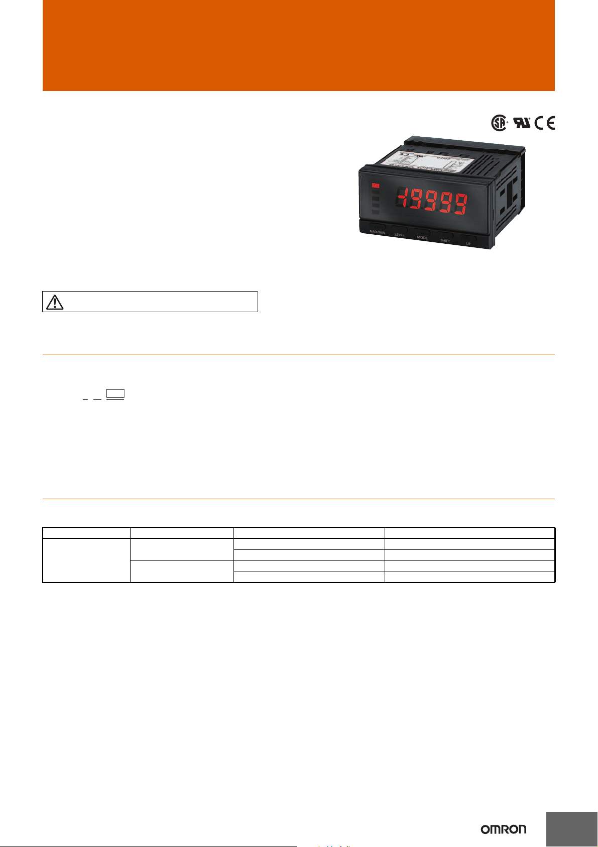
Process Meter
For the most recent information on models that have been certified for
safety standards, refer to your OMRON website.
K3MA-J-@
1 2 3
K3MA-J
Highly Visible LCD Display with 2-color
(Red and Green) LEDs
• Multi-range DC voltage/current input.
• Front-panel key operation for easy setting.
• Average processing function suppresses flicker.
• Scaling, front-panel forced-zero, zero-limit functions.
• Easy confirmation of max/min display.
• Short 80-mm depth (measured from edge of face plate).
• Finger protective cover (standard equipment) guards against electric
shock.
• Water- and dust-proof NEMA4X (IP66 equivalent) front panel.
• Recognized to U.S. and Canadian requirements under the Component Recognition Program of UL.
•CE marking.
Refer to Safety Precautions for All Digital Panel
Meters.
CSM_K3MA-J_DS_E_11_1
Model Number Structure
■ Model Number Legend
1. Input Type
J: DC voltage/current
2. Comparative Output Model
None: No output
A2: 2 relay contact outputs (SPST-NO)
3. Supply Voltage
100-240VAC: 100 to 240 VAC
24VAC/VDC: 24 VAC/VDC
Ordering Information
■ List of Models
Input type Supply voltage Comparative Output Model Model
DC voltage/current 100 to 240 VAC None * K3MA-J 100-240VAC
2 relay contact outputs (SPST-NO) K3MA-J-A2 100-240VAC
24 VAC/VDC None * K3MA-J 24VAC/VDC
2 relay contact outputs (SPST-NO) K3MA-J-A2 24VAC/VDC
* Changing the display color based on comparison with a reference value is not possible.
1
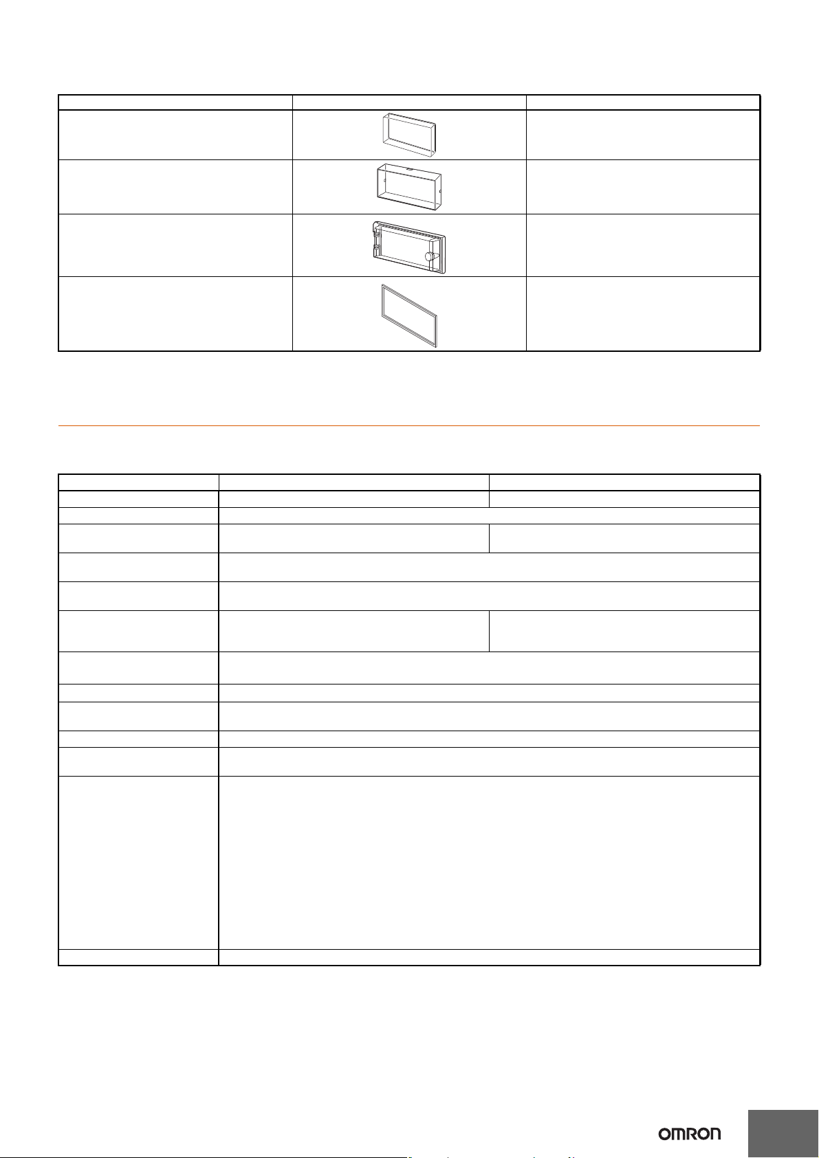
■ Accessories (Order Separately)
Name Shape Model
Splash-proof Soft Cover K32-49SC
Hard Cover K32-49HC
Watertight Cover Y92A-49N
Rubber Packing K32-P1
Note: Rubber packing is provided with the Controller.
Specifications
K3MA-J
■ Ratings
Model K3MA-J 100-240VAC, K3MA-J-A2 100-240VAC K3MA-J 24VAC/VDC, K3MA-J-A2 24VAC/VDC
Supply voltage 100 to 240 VAC 24 VAC/VDC
Operating voltage range 85% to 110% of the rated supply voltage
Power consumption
(under maximum load)
Insulation resistance 20 MΩ min. (at 500 VDC) between external terminal and case.
Dielectric strength 2,000 VAC for 1 min between external terminal and case.
Noise immunity ±1,500 V on power supply terminals in normal or com-
Vibration resistance
Shock resistance
Ambient temperature Operating: −10°C to 55°C (with no condensation or icing)
Ambient humidity Operating: 25% to 85% (with no condensation)
Approved safety standards UL61010-1, CSA C22.2 No.61010-1-04,
EMC (EMI) EN61326+A1 Industry
Weight Approx. 200 g
6 VA max. 4.5 VA max. (24 VAC)
Insulation provided between inputs, outputs, and power supply.
Insulation provided between inputs, outputs, and power supply.
mon mode.
±1 μs, or 100 ns for square-wave noise with 1 ns.
2
Vibration: 10 to 55 Hz, Acceleration: 50 m/s
5 min each in X, Y, and Z directions for 10 sweeps.
2
150 m/s
Storage: −25°C to 65°C (with no condensation or icing)
Conforms to VDE0106/P100 (finger protection)
Emission Enclosure: CISPR 11 Group 1 class A: CISRP16-1/-2
Emission AC Mains: CISPR 11 Group 1 class A: CISRP16-1/-2
(EMS) EN61326+A1 Industry
Immunity ESD: EN61000-4-2: 4 kV contact discharge
Immunity RF-interference: EN61000-4-3: 10 V/m (amplitude-modulated, 80 MHz to 1 GHz)
Electrical Fast Transient Noise: EN61000-4-4: 2 kV (power line)
Immunity Burst Noise: 1 kV line to line (I/O signal line)
Immunity Surge: EN61000-4-5: 1 kV (power line)
Immunity Conducted Disturbance: EN61000-4-6: 3 V (0.15 to 80 MHz)
Immunity Voltage Dip/Interrupting: EN61000-4-11: 0.5 cycle, 0, 180°, 100% (rated voltage)
(100 m/s2 for relay contact outputs) 3 times each on 3 axes, 6 directions.
conforms to EN61010-1 (Pollution degree 2/overvoltage category II)
4.5 W max. (24 VDC)
±480 V on power supply terminals in normal mode.
±1,500 V in common mode.
±1 μs, or 100 ns for square-wave noise with 1 ns.
8 kV air discharge
2 kV line to ground (power line)
2
K3MA-J
■ Characteristics
Input signal DC voltage/current (0 to 20 mA, 4 to 20 mA, 0 to 5 V, 1 to 5 V, ±5 V, ±10 V)
A/D conversion Double integral method
Sampling period 250 ms
Display refresh period Sampling period (sampling times multiplied by number of measurements for averaging if average pro-
Max. displayed digits 5 digits (−19999 to 99999)
Display 7-segment digital display, Character height: 14.2 mm
Polarity display “−” is displayed automatically with a negative input signal.
Zero display Leading zeros are not displayed.
Scaling function Programmable with front-panel key inputs (range of display: −19999 to 99999). The decimal point po-
Hold function Max. hold (maximum value), Min. hold (minimum value)
Hysteresis setting Programmable with front-panel key inputs (0001 to 9999).
Other functions Forced-zero (with front-panel key)
Output Relays: 2 SPST-NO
Delay in comparative outputs 750 ms max.
Degree of protection Front panel: NEMA4X for indoor use (equivalent to IP66)
Memory protection Non-volatile memory (EEPROM) (possible to rewrite 100,000 times)
cessing is selected.)
sition can be set as desired.
Zero-limit
Scaling teach function
Display color change (green (red), green, red (green), red)
OUT type change (upper limit, lower limit, upper/lower limit)
Average processing (simple average)
Rear case: IEC standard IP20
Terminals: IEC standard IP00 + finger protection (VDE0106/100)
■ Measuring Ranges
Process Voltage/Current Inputs
Input Measuring range Measuring accuracy Input impedance Displayable range
DC voltage 1.000 to 5.000 V ±0.1% FS ±1 digit max.
0.000 to 5.000 V
–5.000 to 5.000 V ±0.1% FS ±1 digit max.
–10.00 to 10.00 V
DC current 4.00 to 20.00 mA/
0.00 to 20.00 mA
(at 23±3°C)
(at 23±5°C)
±0.1% FS ±1 digit max.
(at 23±3°C)
1 MΩ min. –19999 to 99999
(with scaling function)
45 Ω
■ Input/Output Ratings
Relay Contact Output
Item Resistive load (cosφ = 1) Inductive load (cosφ = 0.4, L/R=7 ms)
Rated load (UL ratings) 5 A at 250 VAC, 5 A at 30 VDC 1.5 A at 250 VAC, 1.5 A at 30 VDC
Max. contact voltage 250 VAC, 150 VDC
, 150 W 250 VA, 30 W
Max. switching capacity 1,250 V
Min. permissible load
(P level, reference value)
Mechanical life 5,000,000 times min. (at a switching frequency of 1,200 times/min)
Electrical life
(at an ambient temperature of 20°C)
A
10 mA at 5 VDC
100,000 times min. (at a rated load switching frequency of 10 times/min)
3
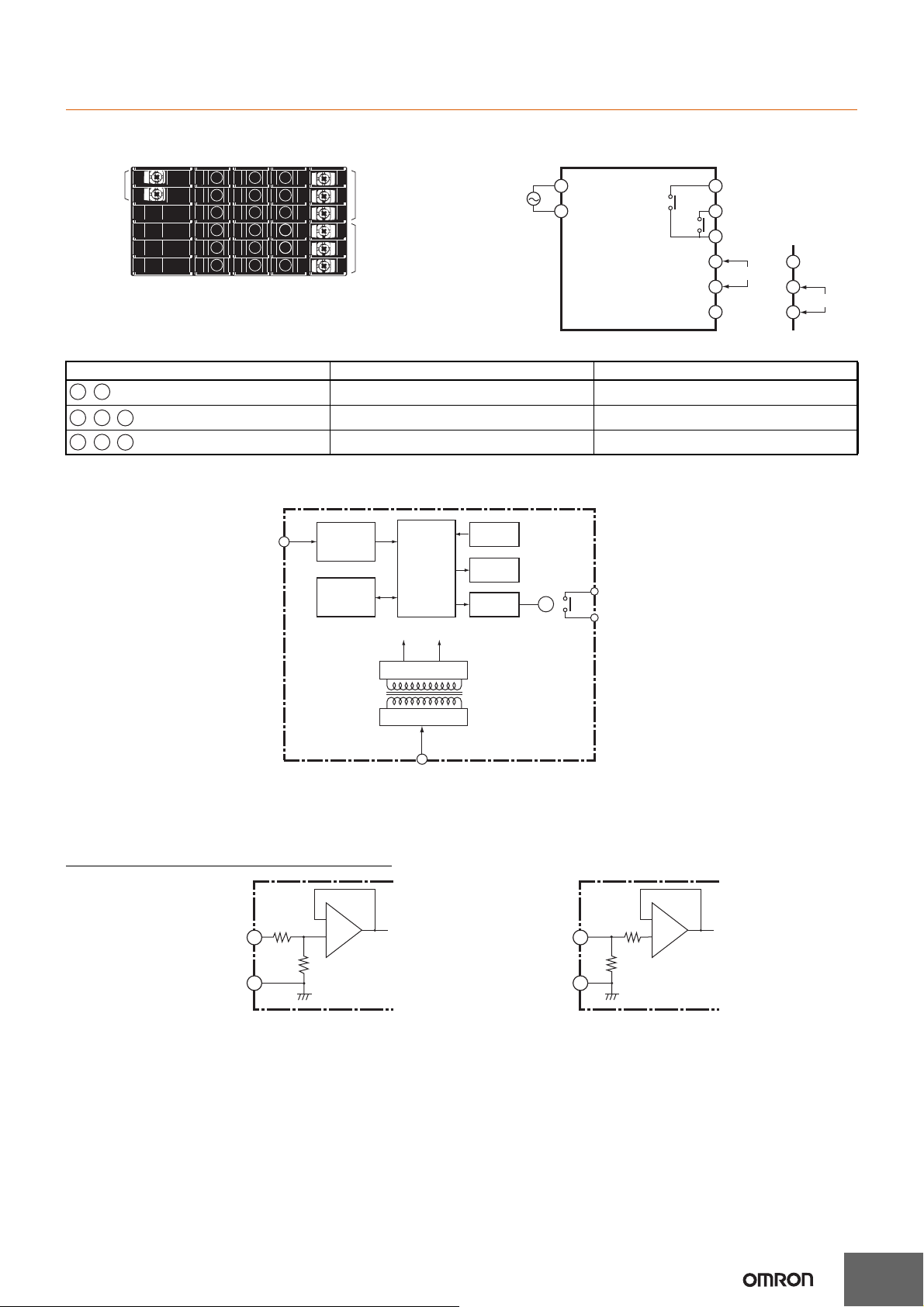
Connections
Power
supply
Output
terminals
Input
terminals
A1 A2
-
E4 E6
,
E5
-
E1 E2
,
E3
-
X
5 V 12 V
Input Input circuit
Microcomputer
Key
Display
Output
circuit
Contact output
(See note.)
Constant voltage circuit
Power supply circuit
EEPROM
Note: Relay output models only.
■ Terminal Arrangement
Terminal No. Name Description
■ Block Diagram
K3MA-J
Models with
A1
comparative
output
100- to 240-VAC
type or 24-VAC/
VDC type
(No polarity for
24-VDC
connection.)
A2
OUT1
Operation power Connects the operation power supply.
Analog input Connects the voltage or current analog input.
Outputs Outputs the relay outputs.
E1
E2
OUT2
E3
E4
Voltage input
E5
COM
E6
For voltage input For current input
E4
COM
E5
Current input
E6
■ Input Circuits
Analog Input (DC Voltage/Current)
Voltage input
COM
4
5
A
−
+
B
To A/D
A+B=1 MΩ
Current input
COM
6
5
45 Ω
−
+
To A/D
4
Operation
()()
()
()
()
()
()
()
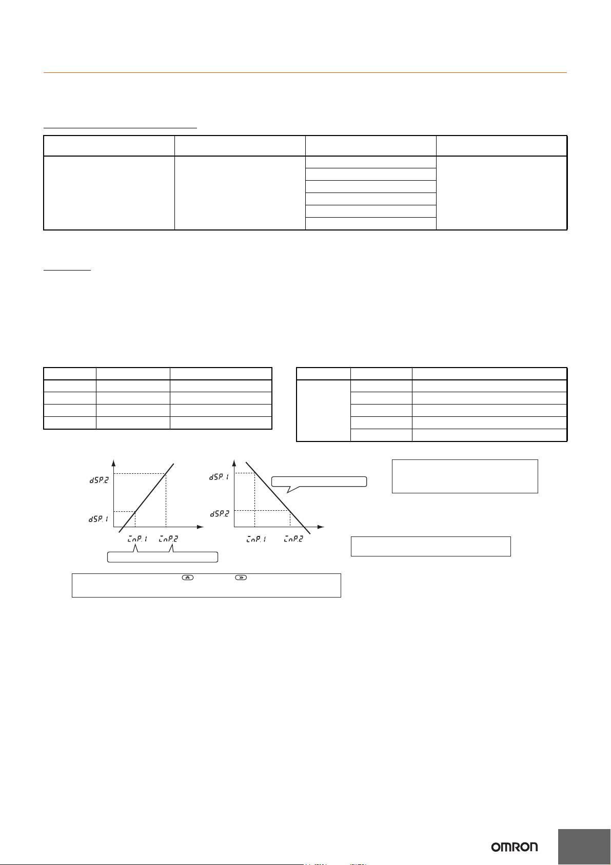
Reverse scaling also possible.
Input value
Input value
Display value Display value
DISPLAY 2
DISPLAY 1
DISPLAY 1
DISPLAY 2
INPUT 1
INPUT 2
INPUT 1 INPUT 2
Teaching with actual values is possible.
Instead of setting by inputting with the Up Key and Shift Key, current values can be
input as scaling input values for teaching. This is useful for making settings while checking the
operation status of the K3MA-J.
The decimal point can be optionally displayed.
When displaying the decimal point, consider the
number of digits to follow the decimal point prior to
setting the scaling display value.
Reverse scaling, where the display value decreases as
the input value increases, is also possible.
■ Main Functions
Input Types and Ranges
K3MA-J
Input type (setting parameter) Function Input range
Input range (in-t) Selects DC voltage/current signal
input
(setting parameters)
0 to 20 mA (0-20) Displayable from −19999 to 99999
4 to 20 mA (4-20)
0 to 5 V (0-5)
1 to 5 V (1-5)
with scaling function.
The position of the decimal point
can be set as desired.
Setting range
±5 V (5)
±10 V (10)
Note: The initial value for the input range is “4 to 20 mA (4-20).”
Scaling
• Analog (Process) Inputs
The K3MA-J converts input signals into desired physical values.
INPUT2: Any input value
DISPLAY2: Displayed value corresponding to INPUT2
INPUT1: Any input value
DISPLAY1: Displayed value corresponding to INPUT1
When DISPLAY1 is set for INPUT1, and DISPLAY2 is set for INPUT2, a line will be displayed joining the two points. (Raise shift, reverse scaling,
plus/minus display, etc., can be adjusted as desired.)
Parameter Setting value Meaning Parameter Setting value Meaning
inp.1 -19999 to 99999 Input value for dsp.1 dp %.%%%% Display four digits after decimal point
dsp.1 -19999 to 99999 Input value for inp.1 %%.%%% Display three digits after decimal point
inp.2 -19999 to 99999 Input value for dsp.2 %%%.%% Display two digits after decimal point
dsp.2 -19999 to 99999 Input value for inp.2 %%%%.% Display one digit after decimal point
%%%%% No decimal point
5
K3MA-J
“T” lights to
indicate that the
parameter is
valid for teaching.
Monitor mode
Teaching mode
“T” flashes.
Normal change
“T” turns OFF.
Use to register
and shift to monitor
mode.
Use to shift to
the next parameter
without registering.
Next parameter
Upper Limit (High Acting) Lower Limit (Low Acting)
OUT1/2 value
Measurement value
ON
OFF
Output
ON
OFF
Output
ON
OFF
Output
OUT1/2 value
Measurement value
Measurement value
Hysteresis
Hysteresis
Hysteresis
Hysteresis
Upper and Lower Limits
(Outside Band Acting)
OUT1/2 upper-limit value
OUT1/2 lower-limit value
Upper Limit 2-stage Output Threshold Output Combination of Upper Limit and
Upper/Lower Limits
OUT2
value
OUT1
value
OUT2
OUT1
ON
OFF
OFF
ON
OUT2
OUT1
ON
OFF
OFF
ON
OUT2
OUT1
ON
OFF
OFF
ON
Measurement
value
Measurement
value
Measurement
value
OUT2 upper-limit
value
OUT1 upper-limit
value
OUT1 lower-limit
value
OUT2 lower-limit
value
OUT2 Upper-limit
value
OUT1 value
OUT2 Lower-limit
value
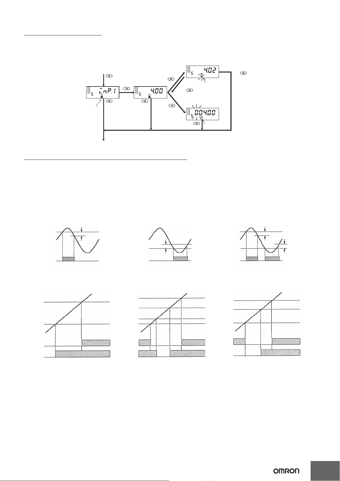
Convenient Functions
Scaling Teach
The parameters (inp.1, inp.2) for the K3MA-J’s initial setting level can be set using actual input values with the teaching function. After displaying
the parameters, the actual input settings can be made with the following operation.
OUT Types (Comparative Output Models Only)
OUT 1 and OUT 2 can be set to operate in one of the three following modes in accordance with the compared values:
• Upper limit (High Acting):
The output is turned ON when the measurement value is greater than its set value.
• Lower limit (Low Acting):
The output is turned ON when the measurement value is less than its set value.
• Upper and lower limits (Outside Band Acting):
An upper limit (H set value) and lower limit (L set value) can be set independently.
The output is turned ON when the measurement value is greater than upper-limit set value or less than the lower-limit set value.
The three types of output operations shown above can be combined as desired. The following are examples of possible combinations.
6
 Loading...