

Omron G9SX-AD322-T15-RT, G9SX-AD322-T150-RC, G9SX-AD322-T15-RC, G9SX-AD322-T150-RT, G9SX-ADA222-T15-RT User Manual
...Page 1
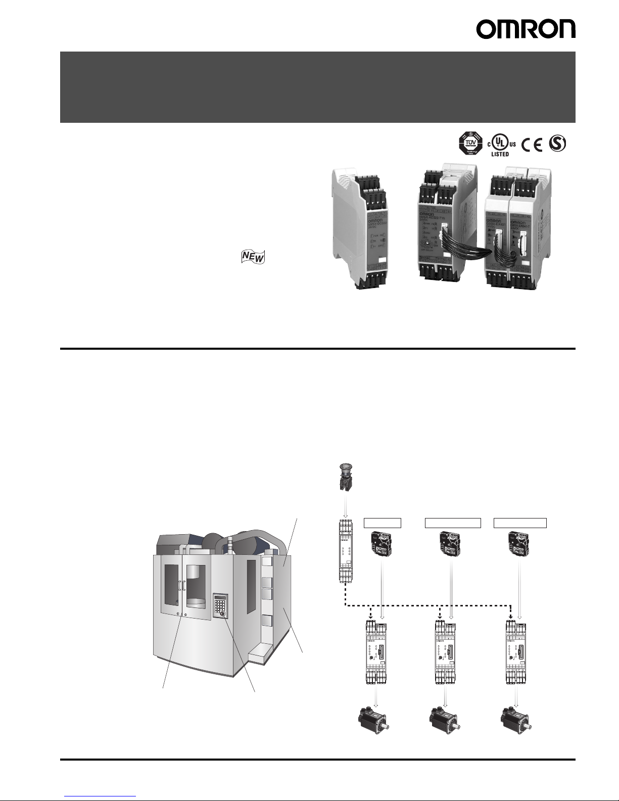
Flexible Safety Unit G9SX 1
Flexible Safety Unit
G9SX
Logical AND Function Adds Flexibility
to I/O Expansion
• Facilitates partial or complete control system setup.
• Solid-state outputs (excluding Expansion Units).
• Detailed LED indications enable easy diagnosis.
• TÜV Product Service certification for compliance
with IEC/EN61508 (SIL3) and EN954-1 (Cat. 4).
• Approved by UL and CSA.
• New unit joins the Series with the following
two additional features:
-OFF-delay time of up to 150 seconds
(The OFF-delay output also complies with Cat. 4.)
-Two logical AND connection inputs
Note: Refer to Precautions on pages 17 and 18.
Features
Basic Unit
G9SX-BC
Advanced Unit
G9SX-AD
Advanced Uni
t
G9SX-AD
Advanced Unit
G9SX-AD
Tool changer door
Pallet changer door
Emergency
Stop Switch
Main door
Main Door
Pallet Changer Door
Tool Changer Door
Safety Door
Switch
Safety Door
Switch
Safety Door
Switch
Logical
connection
Emergency Stop Switch
No.
OFF-DELAY
0.5
0.4
0.3
0.2
15
10
7
5
4
3
2
1.5
1
0.6
0.7
0
S54S44S34S24S14 L1
A2T42T41T22T21
A1X2X1Y1T12T11
T33T31
T1
ERR
EI
AND
FB
ED
T2
PWR
T32
G9SX-AD322-T15
No.
OFF-DELAY
0.5
0.4
0.3
0.2
15
10
7
5
4
3
2
1.5
1
0.6
0.7
0
S54S44S34S24S14 L1
A2T42T41T22T21
A1X2X1Y1T12T11
T33T31
T1
ERR
EI
AND
FB
ED
T2
PWR
T32
G9SX-AD322-T15
No.
OFF-DELAY
0.5
0.4
0.3
0.2
15
10
7
5
4
3
2
1.5
1
0.6
0.7
0
S54S44S34S24S14 L1
A2T42T41T22T21
A1X2X1Y1T12T11
T33T31
T1
ERR
EI
AND
FB
ED
T2
PWR
T32
G9SX-AD322-T15
No.
T1 T2
FB
ERREI
PWR
L2L1S24S14
A2X2T22T21
A1X1T12T11
Y1T32 T33T31
G9SX-BC202
24VDC
● Productivity
“Partial stop” and “Complete stop” enhance productivity without sacrificing safety.
● Maintenance
LED indicators and detachable terminals for better maintenance.
● Expandability
“Logical connection” enables easier modification and expansion of machines.
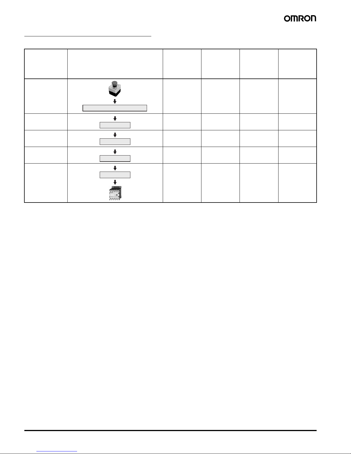
Ex) Machining Center
• When the Emergency Stop Switch is pressed, the entire machine will stop.
• When a door is open, the corresponding part will not activate.
Page 2
2 Flexible Safety Unit G9SX
Model Number Structure
■ Model Number Legend
1. Functions
AD/ADA: Advanced Unit
BC: Basic Unit
EX: Expansion Unit
2. Output Configuration (Instantaneous Safety Outputs)
0: None
2: 2 outputs
3: 3 outputs
4: 4 outputs
3. Output Configuration (OFF-delayed Safety Outputs)
0: None
2: 2 outputs
4: 4 outputs
4. Output Configuration (Auxiliary Outputs)
1: 1 output
2: 2 outputs
5. Max. OFF-delay Time
Advanced Unit
T15: 15 s
T150: 150 s
Basic Unit
No indicator: No OFF delay
Expansion Unit
No indicator: No OFF delay
T: OFF delay
6. Terminal Block Type
RT: Screw terminals
RC: Spring-cage terminals
Ordering Information
■ List of Models
Advanced Unit
Note: 1. The OFF-delay time can be set in 16 steps as follows:
T15: 0/0.2/0.3/0.4/0.5/0.6/0.7/1/1.5/2/3/4/5/7/10/15 s
T150: 0/10/20/30/40/50/60/70/80/90/100/110/120/130/140/150 s
2. The OFF-delayed output becomes an instantaneous output by setting the OFF-delay time to 0 s.
3. P channel MOS FET transistor output
4. PNP transistor output
12 5 634
G9SX-@@@@@@-@@@-@@
Safety outputs
(solid state) (See note 3.)
Auxiliary
outputs
(solid state)
(See note 4.)
Logical AND
connection
No. of
input
channels
Max. OFFdelay time
(See note 1.)
Rated
voltage
Terminal
block type
Model
Instanta-
neous
OFF-delayed
(See note 2.)
Inputs Outputs
3 2 2 1 1 1 or 2
channels
15 s 24 VDC Screw
terminals
G9SX-AD322-T15-RT
Spring-cage
terminals
G9SX-AD322-T15-RC
150 s Screw
terminals
G9SX-AD322-T150-RT
Spring-cage
terminals
G9SX-AD322-T150-RC
2 2 2 15 s Screw
terminals
G9SX-ADA222-T15-RT
Spring-cage
terminals
G9SX-ADA222-T15-RC
150 s Screw
terminals
G9SX-ADA222-T150-RT
Spring-cage
terminals
G9SX-ADA222-T150-RC
Page 3
Flexible Safety Unit G9SX 3
Basic Unit
Note: 1. P channel MOS FET transistor output
2. PNP transistor output
Expansion Unit
Note: 1. PNP transistor output
2. The OFF-delay time is synchronized to the OFF-delay time setting in the connected Advanced Unit (G9SX-AD-@/G9SX-ADA-@).
Specifications
■ Ratings
Power input
Note: Power consumption of loads not included.
Inputs
Outputs
Note: 1. While safety outputs are in the ON state, the following signal sequence is output continuously for diagnosis. When using the safety outputs
as input signals to control devices (i.e. Programmable Controllers), consider the OFF pulse shown below.
2. The following derating is required when Units are mounted side-by-side.
G9SX-AD322-@/G9SX-ADA222-@/G9SX-BC202-@: 0.4 A max. load current
Safety outputs
(solid state) (See note 1.)
Auxiliary outputs
(solid state)
(See note 2.)
Logical AND
connection
No. of
input
channels
Rated
voltage
Terminal block type Model
Instantaneous OFF-delayed Inputs Outputs
2 --- 2 0 2 1 or 2
channels
24 VDC Screw terminals G9SX-BC202-RT
Spring-cage terminals G9SX-BC202-RC
Safety outputs (contact) Auxiliary
outputs
(solid state)
(See note 1.)
OFF-delay
time
Rated voltage Terminal block type Model
Instantaneous OFF-delayed
4 PST-NO --- 1 --- 24 VDC Screw terminals G9SX-EX401-RT
Spring-cage terminals G9SX-EX401-RC
--- 4 PST-NO (See note 2.) Screw terminals G9SX-EX041-T-RT
Spring-cage terminals G9SX-EX041-T-RC
Item G9SX-AD322-@/ADA222-@ G9SX-BC202-@ G9SX-EX-@
Rated supply voltage 24 VDC
Operating voltage range
−15% to 10% of rated supply voltage
Rated power consumption (See note.) 4 W max. 3 W max. 2 W max.
Item G9SX-AD322-@/ADA222-@ G9SX-BC202-@
Safety input Operating voltage: 20.4 VDC to 26.4 VDC, internal impedance: approx. 2.8 k
Ω
Feedback/reset input
Item G9SX-AD322-@/ADA222-@ G9SX-BC202-@
Instantaneous safety output
OFF-delayed safety output (See note 1.)
P channel MOS FET transistor output
Load current:
Using 2 outputs or less: 1 A DC max. (See note 2.)
Using 3 outputs or more: 0.8 A DC max.
P channel MOS FET transistor output
Load current:
Using 1 output: 1 A DC max. (See note 2.)
Using 2 outputs: 0.8 A DC max.
Auxiliary output PNP transistor output
Load current: 100 mA max.
ON
OFF
360 µs max.
Approx. 100 ms
Page 4
4 Flexible Safety Unit G9SX
Expansion Unit
■ Characteristics
Note: 1. When two or more Units are connected by logical AND, the operating time and response time are the sum total of the operating times
and response times, respectively, of all the Units connected by logical AND.
2. Represents the operating time when the safety input turns ON with all other conditions set.
3. Represents the operating time when the logical AND input turns ON with all other conditions set.
4. This does not include the operating time or response time of Advanced Units that are connected.
5. This does not include the operating time or response time of internal relays in the G9SX-EX-@.
6. For the G9SX-@-RT (with screw terminals) only.
Item G9SX-EX-@
Rated load 250 VAC, 3A/30 VDC, 3A (resistive load)
Rated carry current 3 A
Maximum switching voltage 250 VAC, 125 VDC
Item G9SX-AD322-@/ADA222-@ G9SX-BC202-@ G9SX-EX-@
Over-voltage category (IEC/EN 60664-1) II II (Safety relay outputs 13 to
43 and 14 to 44: III)
Operating time (OFF to ON state)
(See note 1.)
50 ms max. (Safety input: ON)
(See note 2.)
100 ms max. (Logical AND
connection input: ON) (See
note 3.)
50 ms max. (Safety input: ON) 30 ms max. (See note 4.)
Response time (ON to OFF state)
(See note 1.)
15 ms max. 10 ms max. (See note 4.)
ON-state residual voltage 3.0 V max. (safety output, auxiliary output)
OFF-state leakage current 0.1 mA max. (safety output, auxiliary output)
Maximum wiring length of safety input and
logic AND input
100 m max.
(External connection impedance: 100
Ω max. and 10 nF max.)
Reset input time (Reset button pressing time) 100 ms min.
Accuracy of OFF-delay time (See note 5.) Within
± 5% of the set value --- Within ± 5% of the set value
Insulation
resistance
Between logical AND connection
terminals, and power supply
input terminals and other input
and output terminals connected
together
20 M
Ω min. (by 100 VDC
megger)
--- ---
Between all terminals connected
together and DIN rail
20 M
Ω min. (at 100 VDC) 100 MΩ min. (at 500 VDC)
Dielectric
strength
Between logical AND connection
terminals, and power supply
input terminals and other input
and output terminals connected
together
500 VAC for 1 min --- ---
Between all terminals connected
together and DIN rail
500 VAC for 1 min 1,200 VAC for 1 min
Between different poles of
outputs
--- ---
Between safety relay outputs
connected together and other
terminals connected together
2,200 VAC for 1 min
Vibration resistance Frequency: 10 to 55 to 10 Hz, 0.375-mm single amplitude (0.75-mm double amplitude)
Mechanical
shock
resistance
Destruction
300 m/s
2
Malfunction
100 m/s
2
Durability Electrical --- 100,000 cycles min.
(rated load, switching
frequency: 1,800 cycles/hour)
Mechanical --- 5,000,000 cycles min.
(switching frequency: 7,200
cycles/hour)
Ambient temperature
−10 to 55°C (no icing or condensation)
Ambient humidity 25% to 85%
Terminal tightening torque (See note 6.) 0.5 N·m
Weight Approx. 200 g Approx. 125 g Approx. 165 g
Page 5

Flexible Safety Unit G9SX 5
Logical AND Connection
Note: 1. See Logical AND Connection Combinations below for details.
2. The number of G9SX-EX401-@ Expansion Units or G9SX-EX041-T-@ Expansion Units (OFF-delayed Model) not included.
3. G9SX-EX401-@ Expansion Units and G9SX-EX041-T-@ Expansion Units (OFF-delayed Model) can be mixed.
Logical AND Connection Combinations
1. One logical AND connection output from an Advanced Unit
G9SX-AD can be logical AND connected to up to four Advanced
Units.
2. Two logical AND outputs from a Basic Unit G9SX-BC can be
logical AND connected to up to eight Advanced Units.
3. Two logical AND outputs from an Advanced Unit G9SX-ADA can
be logical AND connected to up to eight Advanced Units.
4. Any Advanced Unit with logical AND input can be logical AND
connected to Advanced Units on up to five tiers.
5. Two logical AND connection outputs, each from different
Advanced/Basic Units, can be logical AND connected to
a single G9SX-ADA Unit.
6. The largest possible system configuration contains a total of 20
Advanced and Basic Units. In this configuration, each Advanced
Unit can have up to five Expansion Units.
Item G9SX-AD322-@/ADA222-@ G9SX-BC202-@ G9SX-EX-@
Number of Units connected per
logical AND output
4 Units max. ---
Total number of Units connected
by logical AND (See note 2.)
20 Units max. ---
Number of Units connected in
series by logical AND
5 Units max. ---
Max. number of Expansion Units
connected (See note 3.)
--- 5 Units
Maximum cable length for logical
AND input
100 m ---
G9SX-AD
G9SX-ADG9SX-ADG9SX-ADG9SX-AD
G9SX-BC
G9SX-AD
G9SX-ADG9SX-ADG9SX-ADG9SX-AD
G9SX-AD G9SX-AD G9SX-AD
G9SX-AD
G9SX-ADG9SX-ADG9SX-ADG9SX-AD
G9SX-ADA
G9SX-AD G9SX-AD G9SX-AD
G9SX-BC or
G9SX-AD or
G9SX-ADA
G9SX-AD
G9SX-AD
G9SX-AD
G9SX-AD
G9SX-BC G9SX-BC
G9SX-ADA
Number of Units connected
per logical AND output:
4 Units max.
Total number of Units
connected by logical AND:
20 Units max.
Number of Units connected
in series by logical AND:
5 Units max.
Note 1: Basic Unit = G9SX-BC
Advanced Unit = G9SX-AD or G9SX-ADA
Note 2: The G9SX-AD322-T-@ has only one logical AND
output.
Advanced Unit
or Basic Unit
Advanced UnitAdvanced Unit Advanced Unit
Advanced Unit
Advanced Unit Advanced Unit Advanced Unit
Advanced Unit
Advanced Unit Advanced Unit Advanced Unit
Advanced Unit Advanced Unit Advanced Unit
Advanced Unit
Advanced Unit Advanced Unit Advanced Unit
Advanced Unit
Page 6
6 Flexible Safety Unit G9SX
Response Time and Operating Time
The following table shows the response time for two or more Units that are logical AND connected.
Note: 1. The maximum response time (not including Expansion Units) in this block flow diagram is the time it takes the output from the Unit on the
lowest tier to switch from ON to OFF after the input to the Unit on the highest tier switches from ON to OFF.
2. The maximum response time (including Expansion Units) in this block flow diagram is the time it takes the output from the Expansion Unit
connected to the Unit on the lowest tier to switch from ON to OFF after the input to the Unit on the highest tier switches from ON to OFF.
3. The maximum operating time (not including Expansion Units) in this block flow diagram is the time it takes the output from the Unit on
the lowest tier to switch from OFF to ON after the input to the Unit on the highest tier switches from OFF to ON.
4. The maximum operating time (including Expansion Units) in this block flow diagram is the time it takes the output from the Expansion
Unit connected to the Unit on the lowest tier to switch from OFF to ON after the input to the Unit on the highest tier switches from OFF to
ON.
Item Block flow diagram Max. response
time (not
including
Expansion
Units)
(See note 1.)
Max. response
time (including
Expansion
Units)
(See note 2.)
Max. operating
time (not
including
Expansion
Units)
(See note 3.)
Max. operating
time (including
Expansion
Units)
(See note 4.)
Tier
First tier 15 ms 25 ms 50 ms 80 ms
Second tier 30 ms 40 ms 150 ms 180 ms
Third tier 45 ms 55 ms 250 ms 280 ms
Fourth tier 60 ms 70 ms 350 ms 380 ms
Fifth tier 75 ms 85 ms 450 ms 480 ms
Advanced Unit or Basic Unit
Advanced Unit
Advanced Unit
Advanced Unit
Advanced Unit
Page 7
Flexible Safety Unit G9SX 7
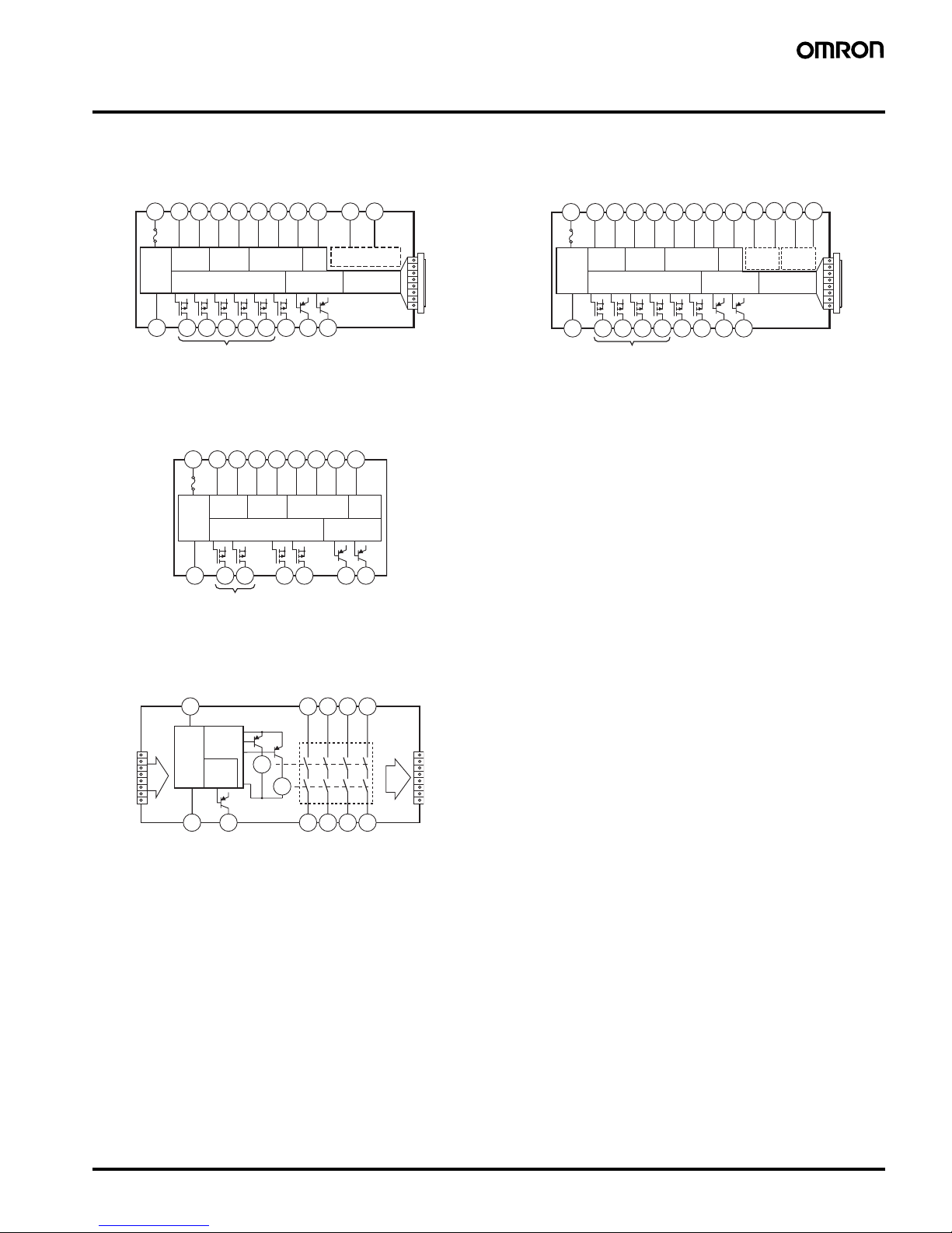
Connections
■ Internal Connection
G9SX-AD322-@ (Advanced Unit)
Note: 1. Internal power supply circuit is not isolated.
2. Logical AND input is isolated.
3. Outputs S14 to S54 are internally redundant.
G9SX-BC202-@ (Basic Unit)
Note: 1. Internal power supply circuit is not isolated.
2. Outputs S14 and S24 are internally redundant.
G9SX-EX401-@/G9SX-EX041-T-@ (Expansion
Unit / Expansion Unit OFF-delayed model)
Note: 1. Internal power supply circuit is not isolated.
2. Relay outputs are isolated.
G9SX-ADA222-@ (Advanced Unit)
Note: 1. Internal power supply circuit is not isolated.
2. Logical AND inputs are isolated.
3. Outputs S14 to S54 are internally redundant.
(See
note 1.)
(See note 2.)
S14A2S24 S34 S44 S54
L1 X1 X2
Power
supply
circuit
Safety
Input 1
Safety
Input 2
Reset/Feedback
Input
Cross
fault
detection
input
Safety output control
Auxiliary
output control
Logical AND input
Expansion Unit
output control
T11A1 T12 T21 T22 T31 T32 T33 Y1 T41 T42
(
See note 3.
)
(See
note 1.)
Reset/Feedback
Input
Cross
fault
detection
input
S14A2S24 L1 L2
X1 X2
Power
supply
circuit
Safety
Input 1
Safety
Input 2
Safety outputs control
Auxiliary
outputs control
T11A1T12 T21 T22 T31 T32 T33
Y1
(
See note 2.
)
A2 X2
Power
supply
circuit
Auxiliary
output
control
Safety
output
control
A1
K1
13 23 33 43
14 24 34 44
K2
Exp.
sig.
IN
Exp.
sig.
OUT
(See
note 1.)
(See note 2.)
(See
note 1.)
(See
note
2.)
S14A2S24 S44 S54
L1 L2 X1 X2
Power
supply
circuit
Safety
Input 1
Safety
Input 2
Reset/Feedback
Input
Cross
fault
detection
input
Safety output control
Auxiliary
output control
Logical
AND input
Expansion Unit
output control
T11A1 T12 T21 T22 T31 T32 T33 Y1
T41 T42
(See note 3.)
T51 T52
Logical
AND input 2
Page 8
8 Flexible Safety Unit G9SX
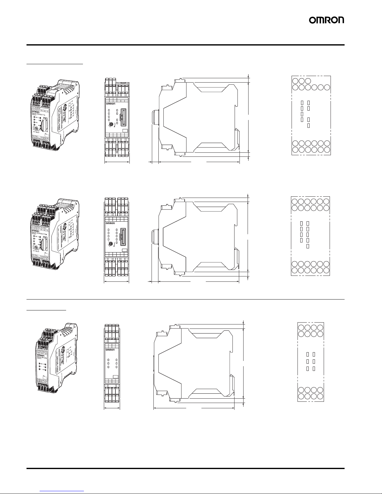
Dimensions
Note: All units are in millimeters unless otherwise indicated.
Advanced Unit
Basic Unit
No.
OFF-DELAY
0.5
0.4
0.3
0.2
15
10
7
5
4
3
2
1.5
1
0.6
0.7
0
S54S44S34S24S14 L1
A2T42T41T22T21
A1X2X1Y1T12T11
T33T31
T1
ERR
EI
AND
FB
ED
T2
PWR
T32
G9SX-AD322-T15
24VDC
(10)
115 max.
100 max.
35.5 max.
(35)*
(6) (See note 2.)
(6) (See note 2.)
* T
yp
ical dimension
FBPWR
T1
AND
EIT2ED
ERR
S44
T41
S14
T21
S24
T22
S34 S54
T42L1A2
T33T32T31
X1Y1
T12T11
X2 A1
Terminal arrangement
Note: 1. Above outline drawing is for -RC terminal type.
2. For -RC terminal type only.
G9SX-AD322-@
FBPWR
T1
AND1
EIT2ED
ERR
AND2
S54
T41
S14
T21
S24
T22
S44
L1
T42
L2
A2
T33T32T31
X1Y1
T12T11
X2 A1
Terminal arrangement
T52T51
(10)
115 max.
100 max.
(6) (See note 2.)
(6) (See note 2.)
* T
yp
ical dimension
No.
OFF-DELAY
0.5
0.4
0.3
0.2
15
10
7
5
4
3
2
1.5
1
0.6
0.7
0
L1S54S44S24S14 L2
A2T42T41T22T21
A1X2X1Y1T12T11
T33T31
T1
ERR
EI
AND1
FB
ED
T2
PWR
T32 T52T51
G9SX-ADA222-T150
24VDC
AND2
35.5 max.
(35)*
A
N
D
1
A
N
D
2
G9SX-ADA222-T150
Note: 1. Above outline drawing is for -RC terminal type.
2. For -RC terminal type only.
G9SX-ADA222-@
No.
T1 T2
FB
ERREI
PWR
L2L1S24S14
A2X2T22T21
A1X1T12T11
Y1T32 T33T31
G9SX-BC202
24VDC
23 max.
(22.5)*
* T
yp
ical dimension
115 max.
100 max.
(6) (See note 2.)
(6) (See note 2.)
FBPWR
T1
EI
T2
ERR
L2
A2
S14
T21
S24
T22L1X2
Y1
T33T32T31
A1X1
T12T11
Terminal arrangement
Note: 1. Above outline drawing is for -RC terminal type.
2. For -RC terminal type only.
G9SX-BC202-@
Page 9
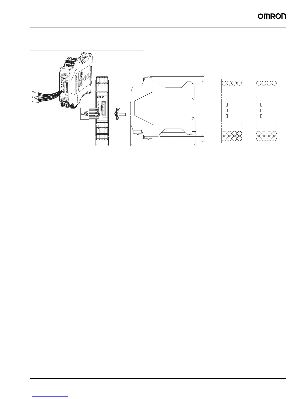
Flexible Safety Unit G9SX 9
Expansion Unit
43332313
44342414
A2X2A1
G9SX-EX401
24VDC
23 max.
(22.5)*
* Typical dimension
115 max.
100 max.
(6) (See note 2.)
(6) (See note 2.
)
43332313
PWR
44
A2
14 24A134
X2
EI
ERR
43332313
PWR
44
A2
14 24A134
X2
ED
ERR
G9SX-EX041-T-@
(Expansion Unit
with OFF Delay)
G9SX-EX401-@
(Expansion Unit)
Terminal arrangement
Note: 1. Above outline drawing is for -RC terminal type.
2. For -RC terminal type only.
G9SX-EX401-@
Expansion Unit (OFF-delayed Model)
G9SX-EX041-T-@
Page 10

10 Flexible Safety Unit G9SX
■ Wiring of Inputs and Outputs
Signal name Terminal name Description of operation Wiring
Power supply input A1, A2 The input terminals for power supply.
Connect the power source to the A1 and A2
terminals.
Connect the power supply plus (24 VDC) to the A1
terminal.
Connect the power supply minus (GND) to the A2
terminal.
Safety input 1 T11, T12 To set the safety outputs in the ON state, the HIGH
state signals must be input to both safety input 1 and
safety input 2. Otherwise the safety outputs cannot
be in the ON state.
Corresponds to
Safety Category
2
Safety input 2 T21, T22 Corresponds to
Safety Category
3
Corresponds to
Safety Category
4
Feedback/reset input T31, T32, T33 To set the safety outputs in the ON state, the ON
state signal must be input to T33.
Otherwise the safety outputs cannot be in the ON
state.
Auto reset
To set the safety outputs in the ON state, the signal
input to T32 must change from the OFF state to the
ON state, and then to the OFF state. Otherwise the
safety outputs cannot be in the ON state.
Manual reset
Logical AND
connection input
T41, T42,
T51, T52
A logical AND connection means that one unit (Unit
A) outputs a safety signal “a” to a subsequent unit
(Unit B) and Unit B calculates the logical
multiplication (AND) (i.e., outputs the AND) of the
signal “a” and safety signal “b”, which is input to Unit
B.
Thereby the logic of the safety output of Unit B is “a”
AND “b”. (An AND of inputs “a” and “b” is output.)
To set the safety outputs of the subsequent Unit in
the ON state, its logical AND connection preset
switch must be set to AND (enable) and the HIGH
state signal must be input to T41 of the subsequent
unit.
Cross fault detection
input
Y1 Selects the mode for the failure detecting (cross fault
detecting) function for the safety inputs of G9SX
corresponding to the connection of the cross fault
detection input.
Keep Y1 open when using T11, T21. (Wiring
corresponding to category 4)
Connect Y1 to 24 VDC when not using T11, T21.
(Wiring corresponding to category 2 or 3, or when
connecting safety sensors)
Instantaneous safety
output
S14, S24, S34 Turns ON/OFF according to the state of the safety
inputs, feedback/reset inputs, and logical AND
connection inputs.
During OFF-delay state, the Instantaneous safety
outputs are not able to turn ON.
Keep these outputs open when not used.
OFF-delayed safety
output
S44, S54 OFF-delayed safety outputs.
The OFF-delay time is set by the OFF-delay preset
switch.
When the delay time is set to zero, these outputs can
be used as non-delay outputs.
Keep these outputs open when not used.
Logical connection
output
L1, L2 Outputs a signal of the same logic as the
instantaneous safety outputs.
Keep these outputs open when not used.
Auxiliary monitor
output
X1 Outputs a signal of the same logic as the
instantaneous safety outputs
Keep these outputs open when not used.
Auxiliary error output X2 Outputs when the error indicator is lit or blinking. Keep these outputs open when not used.
T11 T12 T21 T22
Y1
+24 V
+24 V
T11 T12 T21 T22
Y1
+24 V +24 V
+24 V
T11 T12 T21 T22
Y1
NC
Feedback loop
KM
+24 V
T31 T33T32
Feedback loop
KM
+24 V
T31 T33T32
Reset
Switch
G9SX-BC202 or
G9SX-AD322-T
L1
A2
G9SX-AD322-T
L1
T41 T42
A2
A2
G9SX-AD322-T
Logical AND connection sig. (1st layer)
Next unit (4 unit max.)
Next unit
(
5 layers max.
)
T41 T42
G9SX-AD322-T
L1
T41 T42
Logical AND connection sig. (2nd layer)
Next unit (4 unit max.)
Input b
Input a
Output (a)
Output (a&b)
Unit B
Unit A
Page 11

Flexible Safety Unit G9SX 11
■ Connecting Safety Sensors and the G9SX
1. When connecting safety sensors to the G9SX, the Y1 terminal must be connected to 24 VDC.
The G9SX will detect a connection error, if the Y1 terminal is open.
2. In many cases, safety sensor outputs include an OFF-shot pulse for self diagnosis.
The following condition of test pulse is applicable as safety inputs for the G9SX.
• OFF-shot pulse width of the sensor, during the ON-state: 340
µs max.
Operation
■ Functions
Logical AND Connection
● Example with G9SX-AD322-@
The logical AND connection means that the Basic Unit (or Advanced
Unit) outputs a safety signal “a” to an Advanced Unit, and the
Advanced Unit calculates the logical multiplication (AND) of the
safety signal “a” and safety signal “b.” The safety output of an
Advanced Unit with the logical AND connection shown in the
following diagram is “a” AND “b”.
This is illustrated using the application in the following diagram as an
example. The equipment here has two hazards identified as Robot 1
and Robot 2, and it is equipped with a safety door switch and an
emergency stop button. You may have overall control where both
Robot 1 and Robot 2 are stopped every time the emergency stop
button is pressed. You may also have partial control where only
Robot 1, which is closest to the door, is stopped when the door is
opened. In that case, Robot 2 will continue to operate.
The actual situation using a G9SX for this application is shown in this
example.
(Note: The logical AND setting on the Advanced Unit must be set to
AND (enabled).)
● Example with G9SX-ADA222-@
The Advanced Unit G9SX-ADA222-@ is equipped with two logical
AND connection inputs. Therefore, it is capable of receiving two
safety signals, each from different Advanced or Basic Units. As
shown in the diagram below, the output of Advanced Unit G9SXADA222-@ will be “a” AND “b” AND “c”.
340 µs max.
Basic Unit
G9SX-BC202-@
a
ab
a
(
AND) b
Advanced Unit
G9SX-AD322-@
Logical connection
Basic Unit
Robot 2
ab
Robot 1
Emergency stop button
Advanced Unit
Door Switch
Robot 2
Robot 1
Emergency
stop button
Safety Door
Switch
Logical connection
Basic Unit
G9SX-BC202-
@
a
a
c
a AND b AND c
Advanced Unit
G9SX-ADA222-@
b
b
Basic Unit
G9SX-BC202-@
Page 12

12 Flexible Safety Unit G9SX
Connecting Expansion Units
• The G9SX-EX and G9SX-EX-T Expansion Units can be connected
to an Advanced Unit (G9SX-AD322-@/G9SX-ADA222-@) to
increase the number of safety outputs. (They cannot be connected
to a Basic Unit.)
• A maximum of five Expansion Units can be connected to one
Advanced Unit. This may be a combination of G9SX-EX
Instantaneous types and G9SX-EX-T OFF-delayed types.
• Remove the terminating connector from the receptacle on the
Advanced Unit and insert the Expansion Unit cable connector into
the receptacle. Insert the terminating connector into the receptacle
on the Expansion Unit at the very end (rightmost).
• When Expansion Units are connected to an Advanced Unit, make
sure that power is supplied to every Expansion Unit. (Refer to the
following diagram for actual Expansion Unit connection.)
Setting Procedure
1. Cross Fault Detection (Advanced Unit/
Basic Unit)
Set the cross fault detection mode for safety inputs by shorting Y1 to
24 V or leaving it open. When cross fault detection is set to ON,
short-circuit failures are detected between safety inputs T11-T12 and
T21-22. When a cross fault is detected, the following will occur.
1. The safety outputs and logical AND outputs lock out.
2. The LED error indicator is lit.
3. The error output (auxiliary output) turns ON.
2. Reset Mode (Advanced Unit/Basic Unit)
Set the reset mode using feedback/reset input terminals T31, T32,
and T33.
Auto reset mode is selected when terminal T32 is shorted to 24 V
and manual reset mode is selected when terminal T33 is shorted to
24 V.
3. Setting Logical AND Connection
(Advanced Unit)
When connecting two or more Advanced Units (or Basic Units) by
logical AND connection, set the logical AND connection preset
switch on the Advanced Unit that is on the input side (Advanced Unit
G9SX-AD322 in the following diagram) to AND.
(1) Using G9SX-AD322 on the Input Side
Note: 1. A setting error will occur and Advanced Unit G9SX-AD322
will lock out if the logical AND setting switch on the Unit is
set to OFF.
2. Set the logical AND setting switch on Advanced Unit A to
OFF or an error will occur.
3. A logical AND input cannot be sent to a Basic Unit.
Cross fault
detection
Wiring
OFF Corresponds to
Safety Category 2
Corresponds to
Safety Category 3
ON Corresponds to
Safety Category 4
ED
PWR
A2X2
44342414
A1
33 4313 23
No.
G9SX-EX
24VDC
ED
PWR
A2X2
44342414
A1
33 4313 23
No.
G9SX-EX
24VDC
No.
OFF-DELAY
0.5
0.4
0.3
0.2
15
10
7
5
4
3
2
1.5
1
0.6
0.7
0
S54S44S34S24S14 L1
A2T42T41T22T21
A1X2X1Y1T12T11
T33T31
T1
ERR
EI
AND
FB
ED
T2
PWR
T32
G9SX-AD322-T15
ED
PWR
A2X2
44342414
A1
33 4313 23
No.
G9SX-EX
24VDC
ED
PWR
A2X2
44342414
A1
33 4313 23
No.
G9SX-EX
24VDC
ED
PWR
A2X2
44342414
A1
33 4313 23
No.
G9SX-EX
24VDC
Expansion Unit
Terminating
connector
Advanced Unit
Y1
T22T21T12T11
+24 V
+24 V
Y1
T22T21T12T11
+24 V
+24 V +24 V
Y1
T22T21T12T11
+24 V
+24 V
Auto reset mode
KM1
KM2
KM3
KM4
KM5
KM1
KM2Reset
switch
KM3
KM4
KM5
T33T32T31T33T32T31
Manual reset mode
Advanced Unit
G9SX-AD322
Advanced Unit A
L1 A2
T41 T42
AND
OFF
AND
OFF
Page 13

Flexible Safety Unit G9SX 13
(2) Using G9SX-ADA222 on the Input Side
Note: 1. When not connecting Advanced Unit B, leave terminals T41
and T42 of the G9SX-ADA222 Advanced Unit open, and set
the logical AND setting switch T41/T42 to OFF.
2. When not connecting Advanced Unit C, leave terminals T51
and T52 of the G9SX-ADA222 Advanced Unit open, and set
the logical AND setting switch T51/T52 to OFF.
The following table shows the relationship between the logical ON
setting switches and the conditions for safety outputs turning ON.
4. Setting the OFF-delay Time (Advanced
Unit)
The OFF-delay preset time on an Advanced Unit is set from the OFFdelay time preset switch (1 each on the front and back of the Unit).
Normal operation will only occur if both switches are identically set.
An error will occur if the switches are not identically set.
Refer to the following illustration for details on setting switch
positions.
G9SX-AD322-T15/G9SX-ADA222-T15
G9SX-AD222-T150/G9SX-ADA222-T150
Logical ON setting
switch
Conditions for safety outputs turning
ON
T41/T42 T51/T52 Safety
input
Logic input 1Logic input
2
OFF OFF ON OFF OFF
AND OFF ON ON OFF
OFF AND ON OFF ON
AND AND ON ON ON
Advanced Unit
G9SX-ADA222
Advanced Unit B
L1 A2
T41 T42
Advanced Unit C
L1 A2
T51 T52
T41/T42
T51/T52
AND
OFF
AND
OFF
AND
OFF
AND
OFF
No.
OFF-DELAY
0.5
0.4
0.3
0.2
15
10
7
5
4
3
2
1.5
1
0.6
0.7
0
S54S44S34S24S14 L1
A2T42T41T22T21
A1X2X1Y1T12T11
T33T31
T1
ERR
EI
AND
FB
ED
T2
PWR
T32
AND
OFF
OFF-DELAY
T41/ T42
0
15
10
7
5
4
3
0.2
0.3
0.4
0.5
0.6
0.7
Switch
Switch
Front Back
OFF-DELAY
0.5
0.4
0.3
0.2
15
10
7
5
4
3
2
1.5
1
0.6
0.7
0
OFF-DELAY
0.5
0.4
0.3
0.2
15
10
7
5
4
3
2
1.5
1
0.6
0.7
0
Notch
Example 1: 0-second
OFF-delay
setting
Example 2: 1-second
OFF-delay
setting
cutting edge
ex.1) 0 second off-delay settingex.2) 70 second off-delay settin
g
OFF-DELAY
40
30
20
10
150
140
130
120
110
100
90
80
70
50
60
0
OFF-DELAY
40
30
20
10
150
140
130
120
110
100
90
80
70
50
60
0
Page 14

14 Flexible Safety Unit G9SX
LED Indicators
Note: Refer to Fault Detection on the next page for details.
Settings Indication (at Power ON)
Settings for the G9SX can be checked by the orange indicators for approx. 3 seconds after the power is turned ON. During this settings indication
period, the ERR indicator will light, however the auxiliary error output will remain OFF
Marking Color Name G9SX-AD G9SX-ADA G9SX-BC G9SX-EX G9SX-EX-T Function Reference
PWR Green Power supply
indicator
❍❍ ❍❍❍ Lights up while power is
supplied.
---
T1 Orange Safety input #1
indicator
❍❍ ❍--- --- Lights up while a HIGH state
signal is input to T12.
Blinks when an error relating to
safety input #1 occurs.
(See note.)
T2 Orange Safety input #2
indicator
❍❍ ❍--- --- Lights up while a HIGH state
signal is input to T22.
Blinks when an error relating to
safety input #2 occurs.
FB Orange Feedback/
reset input
indicator
❍❍ ❍--- --- Lights up in the following cases:
With automatic reset while a
HIGH state signal is input to
T33.
With manual reset while a
HIGH state signal is input to
T32.
Blinks when an error relating to
feedback/reset input occurs.
AND Orange Logical AND
input indicator
❍ --- --- --- --- Lights up while a HIGH state
signal is input to T41.
Blinks when an error relating to
logical AND connection input
occurs.
AND1 Orange Logical AND
input indicator
--- ❍ --- --- --- Lights up while a HIGH state
signal is input to T41.
Blinks when an error relating to
logical AND connection input
occurs.
AND2 Orange Logical AND
input indicator
--- ❍ --- --- --- Lights up while a HIGH state
signal is input to T51.
Blinks when an error relating to
logical AND connection input
occurs.
EI Orange Safety output
indicator
❍❍ ❍❍--- Lights up while the
Instantaneous safety outputs
(S14, S24, S34) are in the ONstate.
Blinks when an error relating to
the instantaneous safety output
occurs.
ED Orange OFF-delayed
safety output
indicator
❍❍ --- --- ❍ Lights up while OFF-delayed
safety outputs (S44, S54) are in
the ON-state.
Blinks when an error relating to
OFF-delayed safety output
occurs.
ERR Red Error indicator ❍❍ ❍❍❍ Lights up or blinks when an
error occurs.
Indicator Item Setting position Indicator
status
Setting mode Setting status
T1 Cross fault detection mode Y1 terminal Lit Detection mode Y1 = open
Not lit Non-detection mode Y1 = 24 VDC
FB Reset mode T32 or T33 terminal Lit Manual reset mode T33 = 24 VDC
Not lit Auto reset mode T32 = 24 VDC
AND
(AND1,
AND2)
Logical AND connection input mode Logical AND
connection preset
switch
Lit Enable logical AND input “AND”
Not lit Disable logical AND input “OFF”
Page 15

Flexible Safety Unit G9SX 15
Fault Detection
When the G9SX detects a fault, the ERR indicator and/or other indicators light up or blink to inform the user about the fault.
Check and take necessary measures referring to the following table, and then re-supply power to the G9SX.
(Advanced Unit/Basic Unit)
ERR
indicator
Other
indicator
Fault Expected causes of the fault Check points and measures to take
Blinks
--- Fault due to electro-
magnetic disturbance or of
internal circuits.
1) Excessive electro-magnetic disturbance
2) Failure of the internal circuit
1) Check the disturbance level around the G9SX
and the related system.
2) Replace with a new product.
Lights up
T1 blinks
Fault involved with safety
input 1
1) Failure involving the wiring of safety
input 1
2) Incorrect setting of cross fault detection
input
3) Failure of the circuit of safety input 1
1) Check the wiring to T11 and T12.
2) Check the wiring to Y1.
3) Replace with a new product.
T2 blinks
Fault involved with safety
input 2
1) Failure involving the wiring of safety
input 2
2) Incorrect setting of cross fault detection
input
3) Failure of circuits of safety input 2
1) Check the wiring to T21 and T22.
2) Check the wiring to Y1.
3) Replace with a new product.
FB blinks
Faults involved with
feedback/reset input
1) Failures involving the wiring of feedback/
reset input.
2) Failures of the circuit of feedback/reset
input
1) Check the wiring to T31, T32 and T33.
2) Replace with a new product.
Fault in Expansion Unit 1) Improper feedback signals from
Expansion Unit
2) Abnormal supply voltage to Expansion
Unit
3) Failure of the circuit of safety relay
contact outputs
1) Check the connecting cable of Expansion Unit
and the connection of the termination socket.
2) Check the supply voltage to Expansion Unit.
Note: Make sure that all Expansion units' PWR
indicators are lit.
3) Replace the Expansion Unit with a new one.
EI blinks
Fault involved with
instantaneous safety
outputs or logical
connection outputs or
auxiliary monitor output
1) Failure involving the wiring of
instantaneous safety outputs
2) Failure of the circuit of Instantaneous
safety outputs
3) Failure involving the wiring of the logical
connection output
4) Failure of the circuit of the logical
connection output
5) Failure involving the wiring of the
auxiliary monitor output
6) Impermissible high ambient
temperature
1) Check the wiring to S14, S24, and S34.
2) Replace with a new product.
3) Check the wiring to L1 and L2.
4) Replace with a new product.
5) Check the wiring to X1.
6) Check the ambient temperature and spacing
around the G9SX.
ED blinks
Fault involved with OFFdelayed safety outputs
1) Failure involving the wiring of OFFdelayed safety relay contact outputs
2) Incorrect set values for OFF-delay time
3) Failure of the circuit of OFF-delayed
safety relay contact outputs
4) Impermissible high ambient
temperature
1) Check the wiring to S44 and S54.
2) Confirm the set values of the two OFF-delay
time preset switches.
3) Replace with a new product.
4) Check the ambient temperature and spacing
around the G9SX.
AND blinks
(AND1,
AND2)
Fault involved with logical
AND connection input
1) Failure involving the wiring of the logical
AND connection input
2) Incorrect setting for the logical AND
connection input
3) Failure of the circuit of the logical AND
connection input
1) Check the wiring to T41 and T42 (T51 and
T52).
Note: Make sure that the wiring length for the
T41, T42, T51, T52 terminal is less than
100 meters.
Note: Make sure that the logical AND connection
signal is branched for less than 4 units.
2) Confirm the set value of the logical AND
connection preset switch.
3) Replace with a new product.
All
indicators
except PWR
blink
Supply voltage outside the
rated value
1) Supply voltage outside the rated value 1) Check the supply voltage to Expansion Units.
Page 16

16 Flexible Safety Unit G9SX
When indicators other than the ERR indicator blink, check and take necessary actions referring to the following table.
(Expansion Unit)
ERR
indicator
Other
indicators
Fault Expected cause of the fault Check points and measures to take
Off
T1
Blink
Mismatch between input 1
and input 2.
The input status between input 1 and input
2 is different, due to contact failure or a
short circuit of safety input device(s) or a
wiring fault.
Check the wiring from safety input devices to the
G9SX. Or check the input sequence of safety
input devices. After removing the fault, turn both
safety inputs to the OFF state.
T2
ERR
indicator
Other
indicators
Fault Expected cause of the faults Check points and measures to take
Light up
--- Fault involved with safety
relay outputs of Expansion
Units
1) Welding of relay contacts
2) Failure of the internal circuit
Replace with a new product.
Page 17

Flexible Safety Unit G9SX 17
Precautions
!WARNING
■ Precautions for Safe Use
1. Use G9SX within an enclosure with IP54 protection or higher of
IEC/EN60529.
2. Incorrect wiring may lead to loss of safety function. Wire
conductors correctly and verify the operation of G9SX before
commissioning the system in which G9SX is incorporated.
3. Do not apply DC voltages exceeding the rated voltages, or any
AC voltages to the G9SX power supply input.
4. Use DC supply satisfying requirements below to prevent electric
shock.
• DC power supply with double or reinforced insulation, for
example, according to IEC/EN60950 or EN50178 or a
transformer according to IEC/EN61558.
• DC supply satisfies the requirement for class 2 circuits or limited
voltage/current circuit stated in UL 508.
5. Apply properly specified voltages to G9SX inputs.
Applying inappropriate voltages cause G9SX to fail to perform its
specified function, which leads to the loss of safety functions or
damages to G9SX
6. Auxiliary error outputs and auxiliary monitoring outputs are NOT
safety outputs. Do not use auxiliary outputs as any safety output.
Such incorrect use causes loss of safety function of G9SX and its
relevant system.
Also Logical connection outputs can only be used for logical
connections between G9SXs.
7. After installation of G9SX, qualified personnel should confirm the
installation, and should conduct test operations and maintenance.
The qualified personnel should be qualified and authorized to
secure the safety on each phases of design, installation, running,
maintenance and disposal of system.
8. A person in charge, who is familiar to the machine in which G9SX
is to be installed, should conduct and verify the installation.
9. Turn OFF the signal to Safety input or Logical AND connection
input every 24hours and make sure G9SX operates without faults
by checking the state of the ERR indicator.
10.Do not dismantle, repair, or modify G9SX. It may lead to loss of its
safety functions.
11.Use only appropriate components or devices complying with
relevant safety standards corresponding to the required level of
safety categories.
Conformity to requirements of safety category is determined as
an entire system.
It is recommended to consult a certification body regarding
assessment of conformity to the required safety level.
12.OMRON shall not be responsible for conformity with any safety
standards regarding to customer's entire system.
13.Disconnect G9SX from power supply when wiring, to prevent
electric shock or unexpected operation.
14.Be cautious not to have your fingers caught when attaching
terminal sockets to the plugs on G9SX.
15.The lifetime of G9SX depends on the conditions of switching of its
outputs. Be sure to conduct its test operation under actual
operating conditions in advance and use it within appropriate
switching cycles
16.Do not use in combustible gases or explosive gases. Arcs or heat
generated by switching elements of G9SX can lead to fire or
explosion.
Serious injury may possibly occur due to breakdown of
safety outputs.
Do not connect loads beyond the rated value to the safety
outputs.
Serious injury may possibly occur due to loss of required
safety functions.
Wire G9SX properly so that supply voltages or voltages
for loads do NOT touch the safety inputs accidentally or
unintentionally.
Serious injury may possibly occur due to damages of
safety inputs.
Apply protection circuitry against back electromotive
force in case connecting inductive loads to safety outputs.
Serious injury may possibly occur due to loss of safety
functions. Use devices appropriate for the application and
the condition where G9SX is used.
Control Devices Requirements
Emergency stop switch Use approved devices with Direct
Opening
Mechanism complying with IEC/EN
60947-5-1
Door interlocking switch
Limit switch
Use approved devices with Direct
Opening
Mechanism complying with IEC/EN
60947-5-1 and capable of switching
micro loads of 24VDC, 5mA.
Safety Sensor Use approved devices complying with
the relevant product standards,
regulations and rules in the country
where it is used.
Consult a certification body to assess
that the entire system satisfies the
required safety category level.
Relay with forcibly guided
contacts
Use approved devices with forcibly
guided contacts complying with EN
50205. For feedback purpose use
devices with contacts capable of
switching micro loads of 24VDC, 5mA.
Contactor Use contactors with forcibly guided
mechanism to input the signal to
Feedback/Reset input of G9SX through
the NC contact of the contactor. For
feedback purpose use devices with
contacts capable of switching micro
loads of 24VDC, 5mA. Failure to open
contacts of a contactor cannot be
detected by monitoring its auxiliary NC
contact without forcibly guided
mechanism.
Other devices Evaluate whether devices used are
appropriate to satisfy the requirements
of safety category level.
Page 18

18 Flexible Safety Unit G9SX
■ Precautions for Correct Use
1. Handle with care
Do not drop G9SX to the ground or expose to excessive vibration
or mechanical shocks. G9SX may be damaged and may not
function properly.
2. Conditions of storage
Do not store in such conditions stated below.
a. In direct sunlight
b. At ambient temperatures out of the range of
−10 to 55°C.
c. At relative humidity out of the range of 25% to 85% or under
such temperature change that causes condensation.
d. In corrosive or combustible gases
e. With vibration or mechanical shocks out of the rated values.
f. Under splashing of water, oil, chemicals
g. In the atmosphere containing dust, saline or metal powder.
G9SX may be damaged and may not function properly.
3. Mounting
Mount G9SX to DIN rails with attachments (TYPE PFP-M, not
incorporated to this product), not to drop out of rails by vibration
etc. especially when the length of DIN railing is short compared to
the widths of G9SX.
4. Following spacing around G9SX should be available to apply
rated current to outputs of G9SX and for enough ventilation and
wiring:
a. At least 25 mm beside side faces of the Advanced Unit (G9SX-
AD322-@-@/G9SX-ADA222-@-@) and side faces of the Basic
Unit (G9SX-BC202-@).
b. At least 50 mm above top face of G9SX and below bottom face
of G9SX.
5. Wiring
a. For model G9SX-@-RT (with screw terminals)
• Use the following to wire to G9SX-@-RT.
• Tighten each screw with a specified torque of 0.5 to 0.6Nm,
or the G9SX may malfunction or generate heat.
• Strip the cover of wire no longer than 7mm.
b. For model G9SX-@-RC (with spring-cage terminals)
• Use the following to wire to G9SX-@-RC
• It is recommended that stranded wire should be terminated
with insulation-covered bar terminal (DIN 46228-4 standard
compatible type) at its ends before using for connection.
6. When connecting Expansion Units (G9SX-EX@-@) to Advanced
Unit (G9SX-AD322-@-@/G9SX-ADA222-@-@):
a. Follow the procedure below:
• Remove the termination connector from the receptacle on
Advanced Unit,
• Insert the head of the connecting cable of Expansion Unit to
the receptacle on the Advanced Unit
• Set the termination connector to the receptacle on the
Expansion Unit at the end position. When Advanced Unit is
used without expansion units, leave the termination connector
set on the Advanced Unit.
b. Do not remove the termination connector or the connecting
cable of the Expansion Unit while the system is operating.
c. Before applying supply voltage, confirm that the connecting
sockets and plugs are locked firmly.
d. All of the Expansion Units should be supplied with its specified
voltages within 10s after the connected Advanced Unit is
supplied with voltage.
Otherwise, Advanced Unit detects the power-supply error for
the Expansion Units.
7. Use cables with length less than 100m to connect to Safety
Inputs, Feed-back/Reset inputs, or between Logical AND
connection inputs and Logical connection outputs, respectively.
8. Set the time duration of OFF-delay to an appropriate value that
does not cause the loss of safety function of system.
9. Logical connection between Units:
a. When using Logical AND connection inputs, set the Logical
connection preset switch to 'AND' position for the units which
the logical connection signal are input to.
b. Connect Logical connection outputs appropriately to Logical
AND connection inputs of the relevant unit. Verify the operation
of G9SX before commissioning the system.
c. When configuring the safety related system, be sure to
consider that the delay of response time caused by logical
connections do not degrade the safety function of the system.
10.To determine safety distance to hazards, take into account the
delay of Safety outputs caused by the following time:
a. Response time of Safety inputs
b. Response time of Logical AND connection input
(See also “Ratings and specifications, note 5.”)
c. Preset off-delay time
d. Accuracy of off-delay time
11.Start entire system after more than 5s have passed since
applying supply voltage to all G9SXs in the system.
12.G9SX may malfunction due to electro-magnetic disturbances. Be
sure to connect the terminal A2 to ground. To suppress electrical
noise, apply a surge absorber to the coil of inductive load.
13.Devices connected to G9SX may operate unexpectedly. When
replacing G9SX, disconnect it from power supply.
14.Adhesion of solvent such as alcohol, thinner, trichloroethane or
gasoline on the product should be avoided. Such solvents make
the marking on G9SX illegible and cause deterioration of parts.
15.Do NOT mix AC load and DC load to be switched in one G9SXEX@-@. When switching of both AC load and DC load is
necessary, connect more than two G9SX-EX@-@ and use each
unit for AC load and DC load exclusively.
Solid wire
0.2 to 2.5mm
2
AWG24 to AWG12
Stranded wire
(Flexible wire)
0.2 to 2.5mm
2
AWG24 to AWG12
Solid wire
0.2 to 2.5mm
2
AWG24 to AWG12
Stranded wire
0.34 to 1.5mm
2
AWG22 toAWG16
ED
PWR
A2X2
44342414
A1
33 4313 23
No.
G9SX-EX
24VDC
ED
PWR
A2X2
44342414
A1
33 4313 23
No.
G9SX-EX
24VDC
G9SX-BC202
No.
T1 T2
FB
ERREI
PWB
L2L1S24S14
A2X2T22T21
A1X1T12T11
Y1T32 T33T31
No.
OFF-DELAY
0.5
0.4
0.3
0.2
15
10
7
5
4
3
2
1.5
1
0.6
0.7
0
S54S44S34S24S14 L1
A2T42T41T22T21
A1X2X1Y1T12T11
T33T31
T1
ERR
EI
AND
FB
ED
T2
PWR
T32
G9SX-AD322-T15
25 mm min. 25 mm min.
50 mm min.
50 mm min.
Page 19

Flexible Safety Unit G9SX 19
Category of EN 954-1
In the condition shown in Application Examples, G9SX can be used
for the corresponding categories up to category 4.
This does NOT mean that G9SX can always be used for required
category under all the similar conditions and situations.
Conformity to the categories must be assessed as a whole system.
When using G9SX for safety categories, be sure to confirm the
conformity as a whole system.
1. Input the signals to both of the Safety inputs (T11-T12 and T21T22).
2. Input a signal to the Safety inputs (T11-T12 and T21-T22) through
switches with Direct Opening Mechanism.
When using limit switches, at least one of them must have Direct
Opening Mechanism.
3. When connecting Safety sensor with G9SX, use TYPE 4 safety
sensor.
4. Input the signal through a NC contact of the contactor to
Feedback/Reset input (T31-T32 for manual reset or T31-T33 for
auto reset).(Refer to Application Examples)
5. Keep Cross fault detection mode input (Y1) open. However, when
connecting devices with self-diagnosis function, such as safety
sensors, apply 24VDC to Y1.
6. Be sure to Connect A2 to ground.
7. When using a G9SX-EX-@-@ Expansion Unit, connect fuses with
a current rating of 3.15 A max. to the safety relay outputs to
prevent the contacts from welding.
Compliance with International Standards
G9SX-AD-@/G9SX-ADA-@/G9SX-BC-@/G9SX-EX-@
• Approved by TÜV Product Service
EN50178
IEC/EN60204-1
EN954-1 Cat.4
IEC/EN61508 SIL3
IEC/EN61000-6-2
IEC/EN61000-6-4
• Approved by UL
UL508
UL1998
NFPA79
IEC61508
• Approved by CSA
CAN/CSA C22.2 No.142
Page 20

20 Flexible Safety Unit G9SX
Application Examples
G9SX-AD322-T15 (24 VDC) (1-channel Emergency Stop Switch Input / Manual Reset)
S14A2S24 S34 S44 S54
L1 X1 X2
T11A1T12 T21 T22 T31 T32 T33
Y1
T41 T42
G9SX-AD322-T15
Control circuit
KM2
KM1
KM4
KM3
+24 V
Feedback Loop
+24 V
12
11
+24 V
KM1 KM2 KM3 KM4
S3
4
M1
KM2
KM1
M2
KM4
KM3
Motor controller
OFF
AND
PLC etc.
S1
NCNCNCNC
Motor controller
(Operation command)
GND
S2
KM1, KM2 N.C. contact
KM3, KM4 N.C. contact
KM1, KM2 N.O. contact
OFF-delay time
KM3, KM4 N.O. contact
Operation command
Rotation of motor
Timing chart
Emergency stop switch S1
Reset switch S2
S1: Emergency Stop Switch
S2: Reset Switch S2
KM1 to KM4: Contactor
M1, M2: 3-phase motor
Note: This example corresponds to category 2 (EN 954-1)
Page 21

Flexible Safety Unit G9SX 21
G9SX-AD322-T15 (24 VDC) (2-channel Safety Sensor / Auto Reset)
S14A2S24 S34 S44 S54
L1 X1 X2
T11A1T12 T21 T22 T31 T32 T33
Y1
T41 T42
+24 V+24 V
+24 V
KM1 KM2 KM3 KM4
S34
M1
KM2
KM1
M2
KM4
KM3
Motor controller
OFF
AND
F3SN-A
PLC etc.
Receiver Emitter
Motor controller
(Op
eration command
)
OSSD1
OSSD2
GND
GND
G9SX-AD322-T15
Control circuit
NCNCNCNC
KM2
KM1
KM4
KM3
Feedback Loop
Safety sensor outputs
KM1, KM2 N.C. contact
KM3, KM4 N.C. contact
KM1, KM2 N.O. contact
Off-delay time
KM3, KM4 N.O. contact
Operation command
Rotation of motor
Timing chart
F3SN-A: Safety sensor
KM1 to KM4: Contactor
M1, M2: 3-phase motor
Note: 1. This example corresponds to category 4 (EN 954-1).
2. For further information of settings and wiring, refer to the catalog or instruction manual of the connected sensor.
3. Use safety sensors with PNP outputs.
Page 22

22 Flexible Safety Unit G9SX
G9SX-BC202 (24 VDC) (2-channel Emergency Stop Switch Input / Manual Reset) +
G9SX-AD322-T15 (24 VDC) (2-channel Safety Limit Switch Input / Auto Reset)
S14A2S24 S34 S44 S54
L1 X1 X2
T11A1T12 T21 T22 T31 T32 T33
Y1
T41 T42
S14A2S24 L1 L2
X1 X2
T11A1T12 T21 T22 T31 T32 T33
Y1
KM2
KM1
S2
12
11 21
22
+24 V
KM1 KM2
M1
KM2
KM1
PLC etc.
S1
+24+24 V
+24 V
KM3 KM4
Motor controller
(Op
eration command
)
KM5 KM6
M2
KM4
KM3
S34
M3
KM6
KM5
Motor controller
OFF
AND
PLC etc.
NC
NC
open
23
24
11
12
S4
S3
Feedback Loop
Feedback Loop
GND
GND
G9SX-AD322-T15
Control circuit
G9SX-BC202
Control circuit
KM4
KM3
KM6
KM5
G9SX-BC202 (upper unit)
Reset switch S2
Emergency stop switch S1
KM1, KM2 N.C. contact
KM1, KM2 N.O. contact
Logical AND output L1
Logical AND input T41
KM3, KM4 N.C. contact
Limit switch S4
Safety limit switch S3
KM5, KM6 N.C. contact
KM3, KM4 N.O. contact
OFF-delay tim
e
KM5, KM6 N.O. contact
Operation command
(1) Door opened: Only the lower Unit stops.
(2) Emergency stop button pressed: Both the upper and lower Unit stop.
Rotation of motor
OFF-delay time
G9SX-AD322-T15 (lower unit)
(1)
(2)
Timing chart
Note: This example corresponds to category 4 (EN 954-1).
S3: Safety limit switch
S4: Limit switch
KM3 to KM6: Contactor
M2, M3: 3-phase motor
S1: Emergency Stop Switch
S2: Reset Switch
KM1, KM2: Contactor
M1: 3-phase motor
Page 23

Flexible Safety Unit G9SX 23
G9SX-AD322-T15 (24 VDC) + G9SX-EX041-T (24 VDC)
(Guard Lock Safety Door Switch (Mechanical Lock), 2-channel Safety Limit Switch Inputs /
Manual Reset)
S34
Motor controller
(Operation command)
S14A2S24 S34 S44 S54
L1 X1 X2
T11A1T12 T21 T22 T31 T32 T33
Y1
T41 T42
KM2
KM6
KM1
+24 V +24 V
Feedback Loop
Stop signal
Guard
+24 V
KM1
KM5 KM6
KM2 KM3 KM4
M1
KM2
KM1
M3
KM6
KM5
M2
KM4
KM3
Motor controller
OFF
AND
GND
G9SX-AD322-T15
G9SX-EX041-T
Control circuit
Control
circuit
A2 X2
A1
K1
13 23 33 43
14 24 34 44
K2
Lock release signal
S3
NC NC NC
(See note 2.)
(See note 2.)
PLC etc.
S2
OPEN
S4
31
32
11
12
S1
KM2
KM6
KM1
Limit switch S1
Lock release signal
S4
Stop signal
Reset switch S3
KM1, KM2 N.C. contact
KM1, KM2 N.O. contact
KM3 to KM6 N.C. contact
KM3 to KM6 N.O. contact
Operation command
Rotation of motor
Guard lock safety door switch S2
OFF-dela
y
time
Guard can be opened.
Guard closed → opened
Timing chart
S1: Safety limit switch
S2: Guard lock safety door switch
S3: Reset switch
S4: Lock release switch
KM1 to KM6: Contactor
M1 to M3: 3-phase motor
Note: 1. This example corresponds to category 4 (EN 954-1).
2. Connect the N.C. contacts of contactors KM1, KM2, KM3,
KM4, KM5, and KM6 in series.
Page 24

24 Flexible Safety Unit G9SX
G9SX-BC202 (24 VDC) (2-channel Emergency Stop Switch Input/Manual Reset) +
G9SX-AD322-T15 (24 VDC) (2-channel Safety Limit Switch Input/Auto Reset) +
G9SX-AD322-T15 (24 VDC) (2-channel Safety Limit Switch Input/Auto Reset) +
G9SX-ADA222-T150 (24 VDC) (2-channel Safety Limit Switch Input/Auto Reset) +
Note: This example corresponds to category 4.
S14A2S24 S34 S44 S54
L1 X1 X2
T11A1T12 T21 T22 T31 T32 T33Y1T41 T42
S14A2S24 L1 L2
X1 X2
T11A1T12 T21 T22 T31 T32 T33
Y1
KM2
KM1
S2
12
11 21
22
+24 V
KM1 KM2
M1
KM2
KM1
PLC etc.
S1
+24+24 V V
+24 V
KM3 KM4
M2
KM4
KM3
S144
M4
KM8
KM7
Motor controller
OFF
AND
PLC etc.
NC
NC
open
23
24
11
12
S4
S3
Feedback Loop
Feedback Loop
GND
GND
G9SX-AD322-T15 (Unit B)
Control circuit
G9SX-BC202 (Unit A)
Control circuit
KM4
KM3
S1: Emergency stop switch
S2: Reset switch
S3, S5, S7: Safety limit switch
S4, S6, S8: Limit switch
KM1 to KM8: Contactor
M1 to M4: 3-phase motor
Guard 1
S14A2S24 S34 S44 S54
L1 X1 X2
T11A1T12 T21 T22 T31 T32 T33Y1T41 T42
+24
+24 V V
KM5 KM6
M3
KM6
KM5
OFF
AND
PLC etc.
NC
open
23
24
11
12
S6
S5
GND
G9SX-AD322-T15 (Unit C)
Control circuit
KM6
KM5
Guard 2
S14A2S24 S44 S54
L1 X1 X2
T11A1T12 T21 T22 T31 T32 T33Y1T41 T42
+24+24 V V
Motor controller
(Op
eration command
)
OFF
AND
PLC etc.
NC
open
23
24
11
12
S8
S7
Feedback Loop
GND
G9SX-ADA222-T150 (Unit D)
Control circuit
KM8
KM7
Guard 3
T51 T52
T41 T51
KM7 KM8
L2
Feedback Loop
Page 25

Flexible Safety Unit G9SX 25
(3)
Timing chart
G9SX-BC202 (Unit A)
Emergency stop switch S1
Reset switch S2
KM1, KM2, N.C. contact
KM1, KM2, N.O. contact
Logical AND output L1, L2
G9SX-AD322-T15 (Unit B)
Logical AND input T41
Safety limit switch S3
Limit switch S4
KM3, KM4, N.C. contact
KM3, KM4, N.O. contact
Logical AND output L1
G9SX-AD322-T15 (Unit C)
Logical AND input T41
Safety limit switch S5
Limit switch S6
KM5, KM6, N.C. contact
KM5, KM6, N.O. contact
Logical AND output L1
G9SX-ADA222-T150 (Unit D)
Logical AND input T41
Safety limit switch S7
Limit switch S8
KM7, KM8, N.C. contact
KM7, KM8, N.O. contact
Rotation of motor
Logical AND input T51
Operation command
OFF-delay time OFF-delay time OFF-delay time
(1) Guard 1 opened: Unit B and Unit D stops.
(2) Guard 3 opened: Unit D stops.
(3) Emergency stop button pressed: All units stop.
(1)
(2)
Page 26

26 Flexible Safety Unit G9SX
Page 27

Flexible Safety Unit G9SX 27
Page 28

In the interest of product improvement, specifications are subject to change without notice.
ALL DIMENSIONS SHOWN ARE IN MILLIMETERS.
To convert millimeters into inches, multiply by 0.03937. To convert grams into ounces, multiply by 0.03527.
Cat. No. J150-E1-04
OMRON Corporation
Industrial Automation Company
Safety Devices Division
Shiokoji Horikawa, Shimogyo-ku,
Kyoto, 600-8530 Japan
Tel: (81)75-344-7093/Fax: (81)75-344-8197
0106
Warranty and Application Considerations
Read and Understand this Catalog
Please read and understand this catalog before purchasing the products. Please consult your OMRON representative if you
have any questions or comments.
Warranty and Limitations of Liability
WARRANTY
OMRON's exclusive warranty is that the products are free from defects in materials and workmanship for a period of one year (or
other period if specified) from date of sale by OMRON.
OMRON MAKES NO WARRANTY OR REPRESENTATION, EXPRESS OR IMPLIED, REGARDING NON-INFRINGEMENT,
MERCHANTABILITY, OR FITNESS FOR PARTICULAR PURPOSE OF THE PRODUCTS. ANY BUYER OR USER
ACKNOWLEDGES THAT THE BUYER OR USER ALONE HAS DETERMINED THAT THE PRODUCTS WILL SUITABLY MEET
THE REQUIREMENTS OF THEIR INTENDED USE. OMRON DISCLAIMS ALL OTHER WARRANTIES, EXPRESS OR
IMPLIED.
LIMITATIONS OF LIABILITY
OMRON SHALL NOT BE RESPONSIBLE FOR SPECIAL, INDIRECT, OR CONSEQUENTIAL DAMAGES, LOSS OF PROFITS,
OR COMMERCIAL LOSS IN ANY WAY CONNECTED WITH THE PRODUCTS, WHETHER SUCH CLAIM IS BASED ON
CONTRACT, WARRANTY, NEGLIGENCE, OR STRICT LIABILITY.
In no event shall the responsibility of OMRON for any act exceed the individual price of the product on which liability is asserted.
IN NO EVENT SHALL OMRON BE RESPONSIBLE FOR WARRANTY, REPAIR, OR OTHER CLAIMS REGARDING THE
PRODUCTS UNLESS OMRON'S ANALYSIS CONFIRMS THAT THE PRODUCTS WERE PROPERLY HANDLED, STORED,
INSTALLED, AND MAINTAINED AND NOT SUBJECT TO CONTAMINATION, ABUSE, MISUSE, OR INAPPROPRIATE
MODIFICATION OR REPAIR.
Application Considerations
SUITABILITY FOR USE
OMRON shall not be responsible for conformity with any standards, codes, or regulations that apply to the combination of
products in the customer's application or use of the products.
Take all necessary steps to determine the suitability of the product for the systems, machines, and equipment with which it will
be used.
Know and observe all prohibitions of use applicable to this product.
NEVER USE THE PRODUCTS FOR AN APPLICATION INVOLVING SERIOUS RISK TO LIFE OR PROPERTY WITHOUT
ENSURING THAT THE SYSTEM AS A WHOLE HAS BEEN DESIGNED TO ADDRESS THE RISKS, AND THAT THE OMRON
PRODUCTS ARE PROPERLY RATED AND INSTALLED FOR THE INTENDED USE WITHIN THE OVERALL EQUIPMENT OR
SYSTEM.
Disclaimers
PERFORMANCE DATA
Performance data given in this catalog is provided as a guide for the user in determining suitability and does not constitute a
warranty. It may represent the result of OMRON's test conditions, and the users must correlate it to actual application
requirements. Actual performance is subject to the OMRON Warranty and Limitations of Liability.
CHANGE IN SPECIFICATIONS
Product specifications and accessories may be changed at any time based on improvements and other reasons. Consult with
your OMRON representative at any time to confirm actual specifications of purchased product.
DIMENSIONS AND WEIGHTS
Dimensions and weights are nominal and are not to be used for manufacturing purposes, even when tolerances are shown.
 Loading...