

Omron CS1W-SCU31-V1, CS1W-SCB21-V1, CJ1W-SCU31-V1, CJ1W-SCU41-V1, CS1W-SCU41-V1 Operation Manual
...Page 1

Cat. No. W336-E1-09
SYSMAC
CS/CJ Series
CS1W-SCB@@-V1
Serial Communications Boards
CS1W-SCU@@-V1 and
CJ1W-SCU@@-V1
Serial Communications Units
OPERATION MANUAL
Page 2

SYSMAC CS/CJ Series
Serial Communications Boards and
Serial Communications Units
Operation Manual
Revised February 2008
Page 3

iv
Page 4

Notice:
OMRON products are manufactured for use according to proper procedures by a qualified operator
and only for the purposes described in this manual.
The following conventions are used to indicate and classify precautions in this manual. Always heed
the information provided with them. Failure to heed precautions can result in injury to people or damage to property.
!DANGER Indicates an imminently hazardous situation which, if not avoided, will result in death or
serious injury. Additionally, there may be property damage.
!WARNING Indicates a potentially hazardous situation which, if not avoided, could result in death or
serious injury. Additionally, there may be property damage.
!Caution Indicates a potentially hazardous situation which, if not avoided, may result in minor or
moderate injury, or property damage.
OMRON Product References
All OMRON products are capitalized in this manual. The word “Unit” is also capitalized when it refers to
an OMRON product, regardless of whether or not it appears in the proper name of the product.
The abbreviation “Ch,” which appears in some displays and on some OMRON products, often means
“word” and is abbreviated “Wd” in documentation in this sense.
The abbreviation “PLC” means Programmable Controller. “PC” is used, however, in some Programming Device displays to mean Programmable Controller.
Visual Aids
The following headings appear in the left column of the manual to help you locate different types of
information.
OMRON, 1999
All rights reserved. No part of this publication may be reproduced, stored in a retrieval system, or transmitted, in any form, or
by any means, mechanical, electronic, photocopying, recording, or otherwise, without the prior written permission of
OMRON.
No patent liability is assumed with respect to the use of the information contained herein. Moreover, because OMRON is constantly striving to improve its high-quality products, the information contained in this manual is subject to change without
notice. Every precaution has been taken in the preparation of this manual. Nevertheless, OMRON assumes no responsibility
for errors or omissions. Neither is any liability assumed for damages resulting from the use of the information contained in
this publication.
Note Indicates information of particular interest for efficient and convenient opera-
tion of the product.
1,2,3...
1. Indicates lists of one sort or another, such as procedures, checklists, etc.
v
Page 5

vi
Page 6

TABLE OF CONTENTS
PRECAUTIONS . . . . . . . . . . . . . . . . . . . . . . . . . . . . . . . . . . . xvii
1 Intended Audience . . . . . . . . . . . . . . . . . . . . . . . . . . . . . . . . . . . . . . . . . . . . . . . . . . . . . . . . xviii
2 General Precautions . . . . . . . . . . . . . . . . . . . . . . . . . . . . . . . . . . . . . . . . . . . . . . . . . . . . . . . xviii
3 Safety Precautions. . . . . . . . . . . . . . . . . . . . . . . . . . . . . . . . . . . . . . . . . . . . . . . . . . . . . . . . . xviii
4 Operating Environment Precautions . . . . . . . . . . . . . . . . . . . . . . . . . . . . . . . . . . . . . . . . . . . xix
5 Application Precautions . . . . . . . . . . . . . . . . . . . . . . . . . . . . . . . . . . . . . . . . . . . . . . . . . . . .xx
6 Conformance to EC Directives . . . . . . . . . . . . . . . . . . . . . . . . . . . . . . . . . . . . . . . . . . . . . . . xxii
7 Unit Versions of CS/CJ-series Serial Communications Boards/Units . . . . . . . . . . . . . . . . . xxiv
8 Functions Added in the Unit Version 1.3 Upgrade . . . . . . . . . . . . . . . . . . . . . . . . . . . . . . . . xxviii
9 Functions Added in the Unit Version 1.2 Upgrade . . . . . . . . . . . . . . . . . . . . . . . . . . . . . . . . xxviii
SECTION 1
Introduction . . . . . . . . . . . . . . . . . . . . . . . . . . . . . . . . . . . . . . 1
1-1 Using this Manual . . . . . . . . . . . . . . . . . . . . . . . . . . . . . . . . . . . . . . . . . . . . . . . . . . . . . . . . . 2
1-2 Overview. . . . . . . . . . . . . . . . . . . . . . . . . . . . . . . . . . . . . . . . . . . . . . . . . . . . . . . . . . . . . . . . 3
1-3 Protocol Overview. . . . . . . . . . . . . . . . . . . . . . . . . . . . . . . . . . . . . . . . . . . . . . . . . . . . . . . . . 7
1-4 Features . . . . . . . . . . . . . . . . . . . . . . . . . . . . . . . . . . . . . . . . . . . . . . . . . . . . . . . . . . . . . . . . . 12
1-5 System Configurations . . . . . . . . . . . . . . . . . . . . . . . . . . . . . . . . . . . . . . . . . . . . . . . . . . . . . 16
1-6 Specifications . . . . . . . . . . . . . . . . . . . . . . . . . . . . . . . . . . . . . . . . . . . . . . . . . . . . . . . . . . . . 23
1-7 Comparison to Previous Products . . . . . . . . . . . . . . . . . . . . . . . . . . . . . . . . . . . . . . . . . . . . . 35
1-8 Selecting the Serial Communications Mode. . . . . . . . . . . . . . . . . . . . . . . . . . . . . . . . . . . . . 41
1-9 Basic Operating Procedure . . . . . . . . . . . . . . . . . . . . . . . . . . . . . . . . . . . . . . . . . . . . . . . . . .42
SECTION 2
Initial Settings and I/O Memory Allocations . . . . . . . . . . . . 61
2-1 Component Names and Functions . . . . . . . . . . . . . . . . . . . . . . . . . . . . . . . . . . . . . . . . . . . . 62
2-2 Data Exchange with the CPU Unit . . . . . . . . . . . . . . . . . . . . . . . . . . . . . . . . . . . . . . . . . . . . 72
2-3 I/O Memory Allocations . . . . . . . . . . . . . . . . . . . . . . . . . . . . . . . . . . . . . . . . . . . . . . . . . . . .74
SECTION 3
Installation and Wiring . . . . . . . . . . . . . . . . . . . . . . . . . . . . . 89
3-1 Installing a Serial Communications Board . . . . . . . . . . . . . . . . . . . . . . . . . . . . . . . . . . . . . . 90
3-2 Installing Serial Communications Units . . . . . . . . . . . . . . . . . . . . . . . . . . . . . . . . . . . . . . . . 91
3-3 Wiring . . . . . . . . . . . . . . . . . . . . . . . . . . . . . . . . . . . . . . . . . . . . . . . . . . . . . . . . . . . . . . . . . . 95
3-4 RS-232C and RS-422A/485 Wiring . . . . . . . . . . . . . . . . . . . . . . . . . . . . . . . . . . . . . . . . . . . 114
SECTION 4
Using Host Link Communications . . . . . . . . . . . . . . . . . . . . 123
4-1 Host Link Communications . . . . . . . . . . . . . . . . . . . . . . . . . . . . . . . . . . . . . . . . . . . . . . . . . 124
4-2 Setup Area Allocations . . . . . . . . . . . . . . . . . . . . . . . . . . . . . . . . . . . . . . . . . . . . . . . . . . . . . 124
4-3 Auxiliary Area and CIO Area Allocations . . . . . . . . . . . . . . . . . . . . . . . . . . . . . . . . . . . . . . 128
4-4 Communications Timing. . . . . . . . . . . . . . . . . . . . . . . . . . . . . . . . . . . . . . . . . . . . . . . . . . . . 132
4-5 Changes from Previous Products . . . . . . . . . . . . . . . . . . . . . . . . . . . . . . . . . . . . . . . . . . . . . 136
4-6 Host Link Function for Replacing Existing PLCs . . . . . . . . . . . . . . . . . . . . . . . . . . . . . . . . 139
vii
Page 7

TABLE OF CONTENTS
SECTION 5
Using Protocol Macros . . . . . . . . . . . . . . . . . . . . . . . . . . . . . . 145
5-1 Overview of the Protocol Macro Functions. . . . . . . . . . . . . . . . . . . . . . . . . . . . . . . . . . . . . . 146
5-2 Setup Area Allocations . . . . . . . . . . . . . . . . . . . . . . . . . . . . . . . . . . . . . . . . . . . . . . . . . . . . . 153
5-3 Auxiliary Area and CIO Area Allocations . . . . . . . . . . . . . . . . . . . . . . . . . . . . . . . . . . . . . . 159
5-4 Using Protocol Macros . . . . . . . . . . . . . . . . . . . . . . . . . . . . . . . . . . . . . . . . . . . . . . . . . . . . . 176
5-5 Simple Backup Function (Backup of Protocol Macro Data). . . . . . . . . . . . . . . . . . . . . . . . . 187
5-6 Enhanced Protocol Macro Functions. . . . . . . . . . . . . . . . . . . . . . . . . . . . . . . . . . . . . . . . . . . 190
SECTION 6
Serial Gateway . . . . . . . . . . . . . . . . . . . . . . . . . . . . . . . . . . . . 195
6-1 Serial Gateway Overview . . . . . . . . . . . . . . . . . . . . . . . . . . . . . . . . . . . . . . . . . . . . . . . . . . .196
6-2 DM Area Allocations (Using Serial Gateway Mode) . . . . . . . . . . . . . . . . . . . . . . . . . . . . . . 201
6-3 Auxiliary Area and CIO Area in Serial Gateway Mode . . . . . . . . . . . . . . . . . . . . . . . . . . . . 204
6-4 Using the Serial Gateway . . . . . . . . . . . . . . . . . . . . . . . . . . . . . . . . . . . . . . . . . . . . . . . . . . .208
6-5 Protocol Conversion . . . . . . . . . . . . . . . . . . . . . . . . . . . . . . . . . . . . . . . . . . . . . . . . . . . . . . . 212
6-6 Serial Gateway. . . . . . . . . . . . . . . . . . . . . . . . . . . . . . . . . . . . . . . . . . . . . . . . . . . . . . . . . . . . 226
6-7 Conditions Requiring Routing Tables . . . . . . . . . . . . . . . . . . . . . . . . . . . . . . . . . . . . . . . . . . 230
6-8 Communications Frames . . . . . . . . . . . . . . . . . . . . . . . . . . . . . . . . . . . . . . . . . . . . . . . . . . . . 237
SECTION 7
No-protocol Mode . . . . . . . . . . . . . . . . . . . . . . . . . . . . . . . . . . 249
7-1 Overview . . . . . . . . . . . . . . . . . . . . . . . . . . . . . . . . . . . . . . . . . . . . . . . . . . . . . . . . . . . . . . . . 250
7-2 Allocation DM Area for No-protocol Mode . . . . . . . . . . . . . . . . . . . . . . . . . . . . . . . . . . . . . 252
7-3 Auxiliary Area and CIO Area Allocations . . . . . . . . . . . . . . . . . . . . . . . . . . . . . . . . . . . . . . 254
7-4 Basic Operating Procedure in No-protocol Mode. . . . . . . . . . . . . . . . . . . . . . . . . . . . . . . . . 260
SECTION 8
Using 1:N NT Links . . . . . . . . . . . . . . . . . . . . . . . . . . . . . . . . 263
8-1 Overview of 1:N NT Links . . . . . . . . . . . . . . . . . . . . . . . . . . . . . . . . . . . . . . . . . . . . . . . . . . 264
8-2 Setup Area Allocations . . . . . . . . . . . . . . . . . . . . . . . . . . . . . . . . . . . . . . . . . . . . . . . . . . . . . 266
8-3 Auxiliary Area and CIO Area Allocations . . . . . . . . . . . . . . . . . . . . . . . . . . . . . . . . . . . . . . 267
SECTION 9
Using Modbus-RTU Slave Mode
(Unit Version 1.3 or Later). . . . . . . . . . . . . . . . . . . . . . . . . . . 273
9-1 Modbus-RTU Slave System. . . . . . . . . . . . . . . . . . . . . . . . . . . . . . . . . . . . . . . . . . . . . . . . . . 274
9-2 Setup Area Allocations (Modbus-RTU Slave Mode) . . . . . . . . . . . . . . . . . . . . . . . . . . . . . . 275
9-3 Auxiliary Area and CIO Area Allocations (Modbus-RTU Slave Mode) . . . . . . . . . . . . . . . 278
9-4 Communications Timing . . . . . . . . . . . . . . . . . . . . . . . . . . . . . . . . . . . . . . . . . . . . . . . . . . . . 290
9-5 Changes from Previous Products. . . . . . . . . . . . . . . . . . . . . . . . . . . . . . . . . . . . . . . . . . . . . . 295
9-6 Modbus-RTU Slave Function for Replacing Existing PLCs. . . . . . . . . . . . . . . . . . . . . . . . . 298
viii
Page 8

TABLE OF CONTENTS
SECTION 10
Loopback Test. . . . . . . . . . . . . . . . . . . . . . . . . . . . . . . . . . . . . 303
10-1 Executing Loopback Tests . . . . . . . . . . . . . . . . . . . . . . . . . . . . . . . . . . . . . . . . . . . . . . . . . .304
10-2 Setup Area Allocations . . . . . . . . . . . . . . . . . . . . . . . . . . . . . . . . . . . . . . . . . . . . . . . . . . . . . 305
10-3 CIO Area Allocations . . . . . . . . . . . . . . . . . . . . . . . . . . . . . . . . . . . . . . . . . . . . . . . . . . . . . . 306
SECTION 11
Troubleshooting and Maintenance . . . . . . . . . . . . . . . . . . . . 307
11-1 Indicator Error Displays . . . . . . . . . . . . . . . . . . . . . . . . . . . . . . . . . . . . . . . . . . . . . . . . . . . . 308
11-2 Status Area Error Indications . . . . . . . . . . . . . . . . . . . . . . . . . . . . . . . . . . . . . . . . . . . . . . . .311
11-3 Troubleshooting . . . . . . . . . . . . . . . . . . . . . . . . . . . . . . . . . . . . . . . . . . . . . . . . . . . . . . . . . . 312
11-4 Error Logs . . . . . . . . . . . . . . . . . . . . . . . . . . . . . . . . . . . . . . . . . . . . . . . . . . . . . . . . . . . . . . . 347
11-5 Cleaning and Inspection . . . . . . . . . . . . . . . . . . . . . . . . . . . . . . . . . . . . . . . . . . . . . . . . . . . . 354
11-6 Replacement Precautions . . . . . . . . . . . . . . . . . . . . . . . . . . . . . . . . . . . . . . . . . . . . . . . . . . .355
Appendices
A Introduction . . . . . . . . . . . . . . . . . . . . . . . . . . . . . . . . . . . . . . . . . . . . . . . . . . . . . . . . . . . . . 359
B CompoWay/F Master Protocol . . . . . . . . . . . . . . . . . . . . . . . . . . . . . . . . . . . . . . . . . . . . . . . 363
C C-mode (Host Link) Command Master . . . . . . . . . . . . . . . . . . . . . . . . . . . . . . . . . . . . . . . . 393
D Host Link FINS Command Master . . . . . . . . . . . . . . . . . . . . . . . . . . . . . . . . . . . . . . . . . . . 417
E Mitsubishi Computer Link Master (A-compatible 1C Frame, Model 1) . . . . . . . . . . . . . . . 441
FE5@K Digital Controller Read Protocol . . . . . . . . . . . . . . . . . . . . . . . . . . . . . . . . . . . . . . . 465
GE5@K Digital Controller Write Protocol . . . . . . . . . . . . . . . . . . . . . . . . . . . . . . . . . . . . . . . 485
H E5ZE Temperature Controller Read Protocol . . . . . . . . . . . . . . . . . . . . . . . . . . . . . . . . . . . 501
I E5ZE Temperature Controller Write Protocol . . . . . . . . . . . . . . . . . . . . . . . . . . . . . . . . . . . 523
JE5@J Temperature Controller Protocol . . . . . . . . . . . . . . . . . . . . . . . . . . . . . . . . . . . . . . . . 543
KES100@ Digital Controller Protocol . . . . . . . . . . . . . . . . . . . . . . . . . . . . . . . . . . . . . . . . . . 559
LK3T@ Intelligent Signal Processor Protocol . . . . . . . . . . . . . . . . . . . . . . . . . . . . . . . . . . . . 599
M V500/V520 Bar Code Reader Protocol . . . . . . . . . . . . . . . . . . . . . . . . . . . . . . . . . . . . . . . . 621
N 3Z4L Laser Micrometer Protocol . . . . . . . . . . . . . . . . . . . . . . . . . . . . . . . . . . . . . . . . . . . . 633
O Visual Inspection System Protocol . . . . . . . . . . . . . . . . . . . . . . . . . . . . . . . . . . . . . . . . . . . 669
P V600/V620 ID Controller Protocol . . . . . . . . . . . . . . . . . . . . . . . . . . . . . . . . . . . . . . . . . . . 689
Q Hayes Modem AT Command Protocol . . . . . . . . . . . . . . . . . . . . . . . . . . . . . . . . . . . . . . . . 727
R Changing Communications Port Settings Using STUP(237) . . . . . . . . . . . . . . . . . . . . . . . 735
Index . . . . . . . . . . . . . . . . . . . . . . . . . . . . . . . . . . . . . . . . . . . . 739
Revision History . . . . . . . . . . . . . . . . . . . . . . . . . . . . . . . . . . . 749
ix
Page 9

x
Page 10

About this Manual:
This manual describes the installation and operation of the SYSMAC CS/CJ-series CS1W-SCB@@-V1
Serial Communications Boards and CS1W-SCU@@-V1 and CJ1W-SCU@@-V1 Serial Communications Units and includes the sections described on the next page.
The Serial Communications Boards are classified as Inner Boards and the Serial Communications
Unit is classified as a CPU Bus Unit.
Please read this manual and all related manuals listed in the following table carefully and be sure you
understand the information provided before attempting to install and operate a Serial Communications
Board or Unit.
Name Cat. No. Contents
SYSMAC CS/CJ-series
CS1W-SCB@@-V1, CS1W-SCU@@-V1,
CJ1W-SCU@@-V1
Serial Communications Boards and
Serial Communications Unit Operation Manual (this
manual)
SYSMAC CS/CJ-series
CQM1H-PRO-E1, CQM1-PRO01-E,
C200H-PRO27-E
Programming Consoles Operation Manual
SYSMAC CS-series CS1G/H-CPU@@H, CS1G/H-
CPU@@-EV1
Programmable Controllers Operation Manual
SYSMAC CJ-series
CJ1G/H-CPU@@H, CJ1M-CPU@@,
CJ1G-CPU@@
Programmable Controllers Operation Manual
SYSMAC CS/CJ-series CS1G/H-CPU@@-EV1,
CS1G/H-CPU@@H,
CJ1G-CPU@@-E, CJ1G/H-CPU@@H
Programmable Controllers Programming Manual
SYSMAC CS/CJ-series CS1G/H-CPU@@H, CS1G/
H-CPU@@-EV1, CJ1G/H-CPU@@H, CJ1G-CPU@@,
CJ1M-CPU@@
Programmable Controllers
Instructions Reference Manual
SYSMAC CS/CJ-series
CS1G-/H-CPU@@H, CS1G/H-CPU@@-E, CS1WSCB@@-V1, CS1W-SCU@@-V1, CJ1G/H-CPU@@H,
CJ1G-CPU@@, CJ1W-CPU@@, CJ1W-SCU@@-V1
Communications Commands Reference Manual
SYSMAC WS02-CXPC1-E-V60
CX-Programmer Operation Manual
SYSMAC WS02-PSTC1-E
CX-Protocol Operation Manual
SYSMAC CS/CJ-series
CS1W-ETN01, CS1W-ETN11, CJ1W-ETN11
Ethernet Unit Operation Manual
W336 Describes the use of Serial Communications Unit
and Boards to perform serial communications with
external devices, including the usage of standard
system protocols for OMRON products.
W341 Provides information on how to program and operate
CS/CJ-series PLCs using a Programming Console.
W339 Describes the installation and operation of the CS-
series PLCs.
W393 Describes the installation and operation of the CJ-
series PLCs.
W394 Describes the ladder diagram programming functions
and other functions supported by CS-series and CJseries PLCs.
W340 Describes the ladder diagram programming instruc-
tions supported by CS-series and CJ-series PLCs.
W342 Describes the Host Link and FINS communications
commands used with CS-series and CJ-series PLCs.
W446 Provides information on how to use the CX-Program-
mer, a programming device that supports the CSseries and CJ-series PLCs.
W344 Describes the use of the CX-Protocol to create proto-
col macros as communications sequences to communicate with external devices.
W343 Describes the installation and operation of CS1W-
ETN01, CS1W-ETN11, and CJ1W-ETN11 Ethernet
Unit.
xi
Page 11

About this Manual, Continued
This manual contains the following sections.
Section 1 introduces the hardware and software functions of the Serial Communications Boards and
the Serial Communications Units, including the communications modes, system configurations, and
specifications.
Section 2 describes the components of the Serial Communications Boards and the Serial Communications Units, the settings required for operation, and the memory allocated in the I/O memory of the
CPU Unit for controlling and monitoring communications.
Section 3 describes how to mounting the Serial Communications Boards and Serial Communications
Units, and how to connect the ports to external devices.
Section 4 describes the procedure and other information required to use Host Link communications.
Section 5 describes the procedure and other information required to use protocol macros.
Section 6 provides an overview of the Serial Gateway, information on I/O memory allocations, and
procedures for using the functions. Information on protocol conversion, routing table requirements, and
communications frames is also provided. The Serial Gateway can be used only for Unit Ver. 1.2 or
later.
Section 7 describes the procedure and other information required to use the no-protocol mode. This
mode is supported for Unit Ver. 1.2 or later only.
Section 8 describes the procedure and other information required to use 1:N NT Links to Programmable Terminals.
Section 9 describes the procedure and other information required to use Modbus-RTU slave mode.
Section 10 describes the procedure and other information required to conduct loopback test to check
the serial ports.
Section 11 describes the troubleshooting and maintenance procedures for the Serial Communications
Boards and the Serial Communications Units.
Appendix A to Appendix Q provide the specifications of the standard system protocols.
Appendix R provides information on using STUP(237) to change serial port settings.
!WARNING Failure to read and understand the information provided in this manual may result in per-
sonal injury or death, damage to the product, or product failure. Please read each section
in its entirety and be sure you understand the information provided in the section and
related sections before attempting any of the procedures or operations given.
xii
Page 12

Read and Understand this Manual
Please read and understand this manual before using the product. Please consult your OMRON
representative if you have any questions or comments.
Warranty and Limitations of Liability
WARRANTY
OMRON's exclusive warranty is that the products are free from defects in materials and workmanship for a
period of one year (or other period if specified) from date of sale by OMRON.
OMRON MAKES NO WARRANTY OR REPRESENTATION, EXPRESS OR IMPLIED, REGARDING NONINFRINGEMENT, MERCHANTABILITY, OR FITNESS FOR PARTICULAR PURPOSE OF THE
PRODUCTS. ANY BUYER OR USER ACKNOWLEDGES THAT THE BUYER OR USER ALONE HAS
DETERMINED THAT THE PRODUCTS WILL SUITABLY MEET THE REQUIREMENTS OF THEIR
INTENDED USE. OMRON DISCLAIMS ALL OTHER WARRANTIES, EXPRESS OR IMPLIED.
LIMITATIONS OF LIABILITY
OMRON SHALL NOT BE RESPONSIBLE FOR SPECIAL, INDIRECT, OR CONSEQUENTIAL DAMAGES,
LOSS OF PROFITS OR COMMERCIAL LOSS IN ANY WAY CONNECTED WITH THE PRODUCTS,
WHETHER SUCH CLAIM IS BASED ON CONTRACT, WARRANTY, NEGLIGENCE, OR STRICT
LIABILITY.
In no event shall the responsibility of OMRON for any act exceed the individual price of the product on which
liability is asserted.
IN NO EVENT SHALL OMRON BE RESPONSIBLE FOR WARRANTY, REPAIR, OR OTHER CLAIMS
REGARDING THE PRODUCTS UNLESS OMRON'S ANALYSIS CONFIRMS THAT THE PRODUCTS
WERE PROPERLY HANDLED, STORED, INSTALLED, AND MAINTAINED AND NOT SUBJECT TO
CONTAMINATION, ABUSE, MISUSE, OR INAPPROPRIATE MODIFICATION OR REPAIR.
xiii
Page 13

Application Considerations
SUITABILITY FOR USE
OMRON shall not be responsible for conformity with any standards, codes, or regulations that apply to the
combination of products in the customer's application or use of the products.
At the customer's request, OMRON will provide applicable third party certification documents identifying
ratings and limitations of use that apply to the products. This information by itself is not sufficient for a
complete determination of the suitability of the products in combination with the end product, machine,
system, or other application or use.
The following are some examples of applications for which particular attention must be given. This is not
intended to be an exhaustive list of all possible uses of the products, nor is it intended to imply that the uses
listed may be suitable for the products:
• Outdoor use, uses involving potential chemical contamination or electrical interference, or conditions or
uses not described in this manual.
• Nuclear energy control systems, combustion systems, railroad systems, aviation systems, medical
equipment, amusement machines, vehicles, safety equipment, and installations subject to separate
industry or government regulations.
• Systems, machines, and equipment that could present a risk to life or property.
Please know and observe all prohibitions of use applicable to the products.
NEVER USE THE PRODUCTS FOR AN APPLICATION INVOLVING SERIOUS RISK TO LIFE OR
PROPERTY WITHOUT ENSURING THAT THE SYSTEM AS A WHOLE HAS BEEN DESIGNED TO
ADDRESS THE RISKS, AND THAT THE OMRON PRODUCTS ARE PROPERLY RATED AND INSTALLED
FOR THE INTENDED USE WITHIN THE OVERALL EQUIPMENT OR SYSTEM.
PROGRAMMABLE PRODUCTS
OMRON shall not be responsible for the user's programming of a programmable product, or any
consequence thereof.
xiv
Page 14

Disclaimers
CHANGE IN SPECIFICATIONS
Product specifications and accessories may be changed at any time based on improvements and other
reasons.
It is our practice to change model numbers when published ratings or features are changed, or when
significant construction changes are made. However, some specifications of the products may be changed
without any notice. When in doubt, special model numbers may be assigned to fix or establish key
specifications for your application on your request. Please consult with your OMRON representative at any
time to confirm actual specifications of purchased products.
DIMENSIONS AND WEIGHTS
Dimensions and weights are nominal and are not to be used for manufacturing purposes, even when
tolerances are shown.
PERFORMANCE DATA
Performance data given in this manual is provided as a guide for the user in determining suitability and does
not constitute a warranty. It may represent the result of OMRON's test conditions, and the users must
correlate it to actual application requirements. Actual performance is subject to the OMRON Warranty and
Limitations of Liability.
ERRORS AND OMISSIONS
The information in this manual has been carefully checked and is believed to be accurate; however, no
responsibility is assumed for clerical, typographical, or proofreading errors, or omissions.
xv
Page 15

xvi
Page 16

PRECAUTIONS
This section provides general precautions for using the CS/CJ-series Serial Communications Boards and Units.
The information contained in this section is important for the safe and reliable application of Programmable
Controllers. You must read this section and understand the information contained before attempting to set up or
operate a PLC system.
1 Intended Audience . . . . . . . . . . . . . . . . . . . . . . . . . . . . . . . . . . . . . . . . . . . . . xviii
2 General Precautions . . . . . . . . . . . . . . . . . . . . . . . . . . . . . . . . . . . . . . . . . . . . xviii
3 Safety Precautions. . . . . . . . . . . . . . . . . . . . . . . . . . . . . . . . . . . . . . . . . . . . . . xviii
4 Operating Environment Precautions . . . . . . . . . . . . . . . . . . . . . . . . . . . . . . . . xix
5 Application Precautions . . . . . . . . . . . . . . . . . . . . . . . . . . . . . . . . . . . . . . . . . xx
6 Conformance to EC Directives . . . . . . . . . . . . . . . . . . . . . . . . . . . . . . . . . . . . xxii
6-1 Applicable Directives . . . . . . . . . . . . . . . . . . . . . . . . . . . . . . . . . . . . xxii
6-2 Concepts . . . . . . . . . . . . . . . . . . . . . . . . . . . . . . . . . . . . . . . . . . . . . . xxii
6-3 Conformance to EC Directives. . . . . . . . . . . . . . . . . . . . . . . . . . . . . xxiii
6-4 EMI Measures for Serial Communications Boards and Units . . . . . xxiii
6-5 EMS Measures for Serial Communications Units . . . . . . . . . . . . . . xxiv
7 Unit Versions of CS/CJ-series Serial Communications Boards/Units . . . . . . xxiv
8 Functions Added in the Unit Version 1.3 Upgrade . . . . . . . . . . . . . . . . . . . . . xxviii
9 Functions Added in the Unit Version 1.2 Upgrade . . . . . . . . . . . . . . . . . . . . . xxviii
xvii
Page 17

Intended Audience 1
1 Intended Audience
This manual is intended for the following personnel, who must also have
knowledge of electrical systems (an electrical engineer or the equivalent).
• Personnel in charge of installing FA systems.
• Personnel in charge of designing FA systems.
• Personnel in charge of managing FA systems and facilities.
2 General Precautions
The user must operate the product according to the performance specifications described in the operation manuals.
Before using the product under conditions which are not described in the
manual or applying the product to nuclear control systems, railroad systems,
aviation systems, vehicles, combustion systems, medical equipment, amusement machines, safety equipment, and other systems, machines, and equipment that may have a serious influence on lives and property if used
improperly, consult your OMRON representative.
Make sure that the ratings and performance characteristics of the product are
sufficient for the systems, machines, and equipment, and be sure to provide
the systems, machines, and equipment with double safety mechanisms.
This manual provides information for programming and operating the Unit. Be
sure to read this manual before attempting to use the Unit and keep this manual close at hand for reference during operation.
!WARNING It is extremely important that a PLC and all PLC Units be used for the speci-
fied purpose and under the specified conditions, especially in applications that
can directly or indirectly affect human life. You must consult with your OMRON
representative before applying a PLC System to the above-mentioned applications.
3 Safety Precautions
!WARNING Provide safety measures in external circuits (i.e., not in the Programmable
Controller), including the following items, to ensure safety in the system if an
abnormality occurs due to malfunction of the PLC or another external factor
affecting the PLC operation. Not doing so may result in serious accidents.
• Emergency stop circuits, interlock circuits, limit circuits, and similar safety
measures must be provided in external control circuits.
• The PLC will turn OFF all outputs when its self-diagnosis function detects
any error or when a severe failure alarm (FALS) instruction is executed.
As a countermeasure for such errors, external safety measures must be
provided to ensure safety in the system.
• The PLC outputs may remain ON or OFF due to deposition or burning of
the output relays or destruction of the output transistors. As a countermeasure for such problems, external safety measures must be provided
to ensure safety in the system.
• When the 24-V DC output (service power supply to the PLC) is overloaded or short-circuited, the voltage may drop and result in the outputs
xviii
Page 18

Operating Environment Precautions 4
being turned OFF. As a countermeasure for such problems, external
safety measures must be provided to ensure safety in the system.
!WARNING Do not attempt to take any Unit apart while the power is being supplied. Doing
so may result in electric shock.
!WARNING Do not touch any of the terminals or terminal blocks while the power is being
supplied. Doing so may result in electric shock.
!WARNING Do not attempt to disassemble, repair, or modify any Units. Any attempt to do
so may result in malfunction, fire, or electric shock.
!Caution Execute online edit only after confirming that no adverse effects will be
caused by extending the cycle time. Otherwise, the input signals may not be
readable.
4 Operating Environment Precautions
!Caution Do not operate the control system in the following places:
• Locations subject to direct sunlight.
• Locations subject to temperatures or humidity outside the range specified
in the specifications.
• Locations subject to condensation as the result of severe changes in temperature.
• Locations subject to corrosive or flammable gases.
• Locations subject to dust (especially iron dust) or salts.
• Locations subject to exposure to water, oil, or chemicals.
• Locations subject to shock or vibration.
!Caution Take appropriate and sufficient countermeasures when installing systems in
the following locations:
• Locations subject to static electricity or other forms of noise.
• Locations subject to strong electromagnetic fields.
• Locations subject to possible exposure to radioactivity.
• Locations close to power supplies.
!Caution The operating environment of the PLC System can have a large effect on the
longevity and reliability of the system. Improper operating environments can
lead to malfunction, failure, and other unforeseeable problems with the PLC
System. Be sure that the operating environment is within the specified conditions at installation and remains within the specified conditions during the life
of the system. Follow all installation instructions and precautions provided in
the operation manuals.
xix
Page 19

Application Precautions 5
5 Application Precautions
Observe the following precautions when using the PLC System.
!WARNING Always heed these precautions. Failure to abide by the following precautions
could lead to serious or possibly fatal injury.
• Always connect to a ground of 100
connecting to a ground of 100
• Always turn OFF the power supply to the PLC before attempting any of
the following. Not turning OFF the power supply may result in malfunction
or electric shock.
• Mounting or dismounting Power Supply Units, I/O Units, CPU Units,
Serial Communications Units, or any other Units.
• Assembling the Units.
• Setting DIP switches or rotary switches.
• Connecting cables or wiring the system.
• Mounting or dismounting terminal blocks.
!Caution Failure to abide by the following precautions could lead to faulty operation of
the PLC or the system, or could damage the PLC or PLC Units. Always heed
these precautions.
• Fail-safe measures must be taken by the customer to ensure safety in the
event of incorrect, missing, or abnormal signals caused by broken signal
lines, momentary power interruptions, or other causes.
• Take appropriate measures to ensure that the specified power with the
rated voltage and frequency is supplied. Be particularly careful in places
where the power supply is unstable. An incorrect power supply may result
in malfunction.
• Tighten the mounting screws at the bottom of Serial Communications
Units to a torque of 0.4 N
malfunction.
• Leave the label attached to the Unit when wiring. Removing the label may
result in malfunction if foreign matter enters the Unit.
• Remove the label after the completion of wiring to ensure proper heat dissipation. Leaving the label attached may result in malfunction.
• Always check polarity before wiring RS-422A/485 connectors. The polarity for the SDA/B and RDA/B signals can be different for some external
devices.
• Check to be sure that terminating resistors have been correctly installed
for RS-422A/485 systems before starting operation.
• Disconnect the LG terminal of the Power Supply Unit from the GR terminal when performing insulation and dielectric strength tests.
• Never turn OFF the power supply while writing protocol macro data.
• Wire all connections correctly according to instructions in this manual.
• Check terminal blocks completely before mounting them.
• Double-check all wiring and switch settings before turning ON the power
supply. Incorrect wiring may result in burning.
⋅m. An incorrect tightening torque may result in
Ω or less when installing the Units. Not
Ω or less may result in electric shock.
xx
Page 20

Application Precautions 5
• Be sure that the Bus Connection Unit and other items with locking devices
are properly locked into place. Improper locking may result in malfunction.
• Check the user program for proper execution before actually running it on
the Unit. Not checking the program may result in an unexpected operation.
• Confirm that no adverse effect will occur in the system before attempting
any of the following. Not doing so may result in an unexpected operation.
• Changing the operating mode of the PLC (including the setting of the
startup operating mode).
• Force-setting/force-resetting any bit in memory.
• Changing the present value of any word or any set value in memory.
• Do not install the product near devices generating strong high-frequency
noise.
• Do not drop the product or subject it to excessive vibration or shock.
• Observe the following precautions for communications cables.
• Do not lay communications cables near power lines or high-voltage
lines.
• Always lay communications cables in ducts.
• Do not pull on the communications cables or bend the communications
cables beyond their natural limit. Doing either of these may break the
cables.
• Do not place objects on top of the communications cables or other wiring lines. Doing so may break the cables.
• Before touching a Unit, be sure to first touch a grounded metallic object in
order to discharge any static built-up. Not doing so may result in malfunction or damage.
• Resume operation only after transferring to the new CPU Unit the contents of the DM Area, HR Area, and other data required for resuming
operation. Not doing so may result in an unexpected operation.
• Do not touch circuit boards or the components mounted to them with your
bare hands. There are sharp leads and other parts on the boards that
may cause injury if handled improperly.
• When transporting or storing Boards, wrap them in material that will protect LSIs, ICs, and other components from static electricity and be sure
that they remain within the storage temperature range.
• When creating Host Link FINS command frames using the CMND(490)
instruction, always set the unit number for Host Link incremented by one
(1 to 32) for the remote destination (send destination) node address (word
C+3, bits 08 to 15 of the CMND(490) instruction). Do not set the unit number of the actual Host Link slave (0 to 31). Using the Host Link unit number without incrementing by one will access the PLC with the entered
Host Link unit number less one.
For example, specify the remote PLC with Host Link unit number 2 by
entering 3 for the remote destination node address. If 2 is entered, the
PLC with Host Link unit number 1 will be accessed.
To access a PLC on a Host Link FINS network using the Serial Gateway
from CX-Programmer, however, enter the actual Host Link unit number,
without incrementing by one. (Select Change PLC, click the Display
Serial Gateway Guide Button, and set unit number in the Host Link
SYSWAY Settings field of the Serial Gateway Guide Dialog Box.
xxi
Page 21

Conformance to EC Directives 6
• When the Serial Gateway is executed during protocol macro execution,
the communications sequence contents and the FINS command reception timing may suspend step transition of the communications sequence
(when the next step does not contain the RECEIVE command, the Serial
Gateway will be executed by interrupting the sequence before the next
step, and the step transition will be suspended).
Use the Serial Gateway send start timeout function to monitor at the
source of the FINS command whether step transition in the communications sequence has been suspended due to execution of the Serial Gateway. If the converted command does not start to be sent within the set
time, either retry executing the FINS command or change the communications sequence.
• When using 2-wire RS-422A/485 communications in Protocol Macro
Mode, set only modem controls for the send control parameters, and do
not use RS/CS flow controls.
• The following operations will result if the Serial Gateway is executed either
using a pre-Ver. 1.2 Board/Unit or using a Ver. 1.2 or later Unit/Board without Serial Gateway or protocol macro mode set for serial communications
at the serial port.
• If either NT Link or loopback test mode is used for serial communications, or if protocol macro mode is used with a pre-Ver. 1.2 Board/Unit,
an undefined command response will be returned (end code: 0401
hex).
• If Host Link mode is used for serial communications, the message will
be converted into a FINS command using Host Link slave-initiated
communications and transferred (this will mainly result in a response
timeout being returned, depending on the remote device (end code:
0205 hex))
• If a no-protocol instruction is sent to a pre-Ver. 1.2 Board/Unit or the serial
port of a Board/Unit with Unit Ver. 1.2 or later using a serial communications mode other than no-protocol mode, the following operations will
occur.
• If TXD(236)/RXD(235) is sent to the Board, Auxiliary Area bit A424204
(Inner Board Service Failure Flag) will turn ON.
• If TXDU(256)/RXDU(255) is sent to the Unit and the serial communications mode is set to protocol macro, NT Link, loopback test, or Serial
Gateway mode, an undefined command error (end code: 0401 hex)
will be returned.
If the serial communications mode is set to Host Link mode and the instruction will be converted to a slave-initiated function FINS command
and transferred. (Depending on the remote device, a response timeout
(end code: 0205 hex) is likely to be returned.)
6 Conformance to EC Directives
6-1 Applicable Directives
•EMC Directives
• Low Voltage Directive
6-2 Concepts
EMC Directives
OMRON devices that comply with EC Directives also conform to the related
EMC standards so that they can be more easily built into other devices or the
xxii
Page 22

Conformance to EC Directives 6
overall machine. The actual products have been checked for conformity to
EMC standards (see the following note). Whether the products conform to the
standards in the system used by the customer, however, must be checked by
the customer.
EMC-related performance of the OMRON devices that comply with EC Directives will vary depending on the configuration, wiring, and other conditions of
the equipment or control panel on which the OMRON devices are installed.
The customer must, therefore, perform the final check to confirm that devices
and the overall machine conform to EMC standards.
Note Applicable EMS (Electromagnetic Susceptibility) and EMI (Electromagnetic
Interference) standards in the EMC (Electromagnetic Compatibility) standards
are as follows:
Unit/Board EMS EMI
CS1W-SCB21-V1/
SCB41-V1
CS1W-SCU21-V1
CJ1W-SCU21-V1
CJ1W-SCU31-V1
CJ1W-SCU41-V1
CS1W-SCU31-V1
Low Voltage Directive
Always ensure that devices operating at voltages of 50 to 1,000 VAC and 75
to 1,500 VDC meet the required safety standards for the PLC (EN61131-2).
EN61131-2
EN61000-6-2
EN61000-6-4
(Radiated emission: 10-m
regulations)
6-3 Conformance to EC Directives
The CS/CJ-series PLCs comply with EC Directives. To ensure that the
machine or device in which the CS/CJ-series PLC is used complies with EC
directives, the PLC must be installed as follows:
1,2,3...
1. The CS/CJ-series PLC must be installed within a control panel.
2. You must use reinforced insulation or double insulation for the DC power
supplies used for the communications power supply and I/O power supplies.
3. CS/CJ-series PLCs complying with EC Directives also conform to the
Common Emission Standard (EN61000-6-4). Radiated emission characteristics (10-m regulations) may vary depending on the configuration of the
control panel used, other devices connected to the control panel, wiring,
and other conditions. You must therefore confirm that the overall machine
or equipment complies with EC Directives.
6-4 EMI Measures for Serial Communications Boards and Units
The CS/CJ-series PLCs conform to the Common Emission Standards
(EN61000-6-4) of the EMC Directives. However, the noise generated from
Serial Communications Board or Unit communications cables may not satisfy
these standards. In such a case, commercially available ferrite cores must be
placed on the communications cable or other appropriate countermeasures
must be provided external to the PLC.
xxiii
Page 23
Unit Versions of CS/CJ-series Serial Communications Boards/Units 7
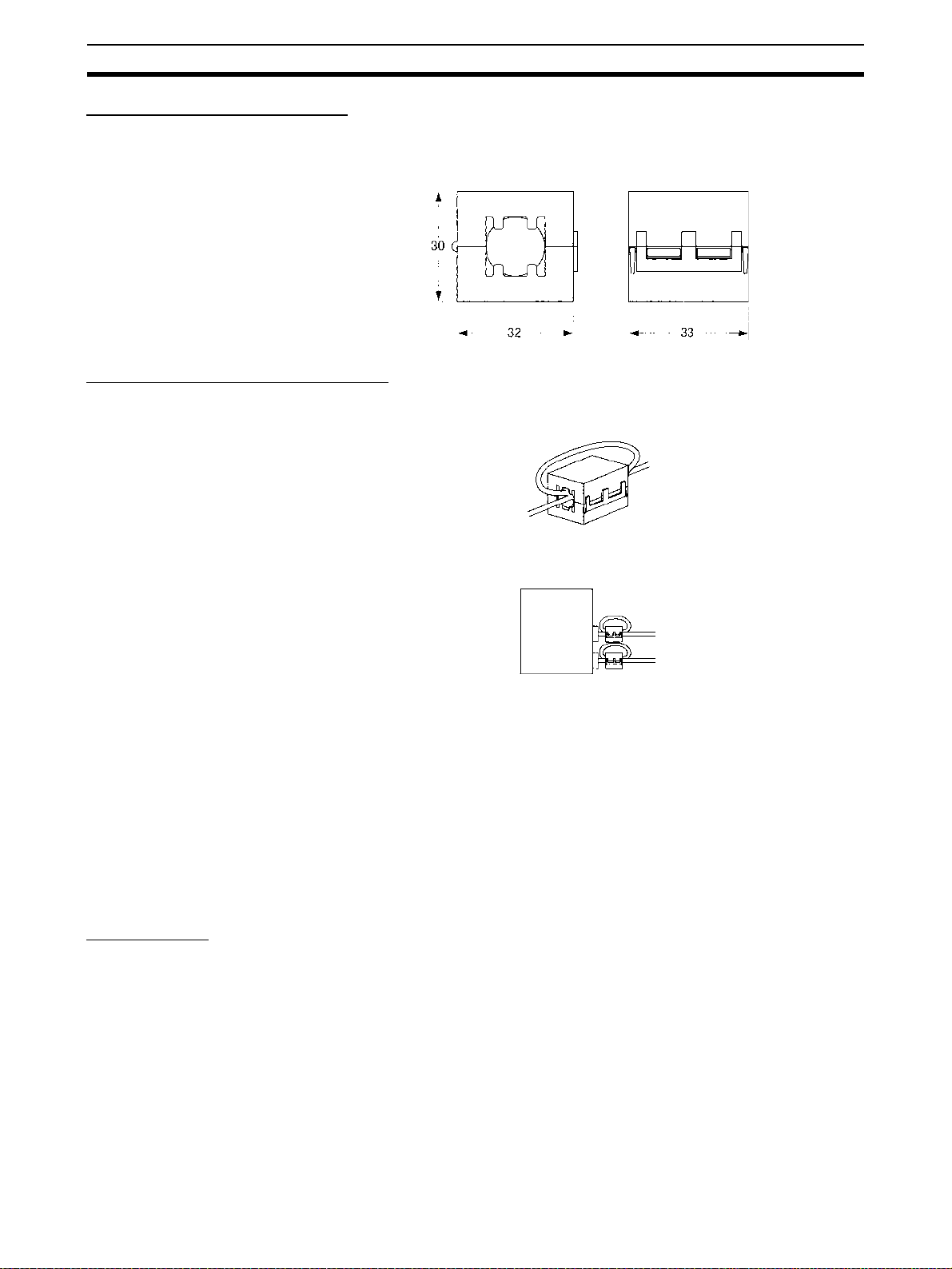
Recommended Ferrite Cores
The following ferrite core (data line noise filter) is recommended:
0443-164151 by Fair-Rite Products Corp.
Low impedance, 25 MHz: 90
Ω, 100 MHz: 160 Ω
Recommended Mounting Method
Mount the core on one turn of the communications cable, as shown in the following illustration.
Mount the cores as lost to the end of the communications cable as possible,
as shown in the following illustration.
Serial
Communications
Unit/Board
6-5 EMS Measures for Serial Communications Units
The immunity testing conditions for the CJ1W-SCU41-V1 Serial Communications Unit are as follows: A ferrite core is mounted on the test cable connected
to the RS-422A/485 port.
Refer to 6-4 EMI Measures for Serial Communications Boards and Units for
information on mounting the ferrite core.
7 Unit Versions of CS/CJ-series Serial Communications
Boards/Units
Unit Versions
A “unit version” has been introduced to manage CS/CJ-series Serial Communications Units/Boards according to differences in functionality accompanying
upgrades.
1. Unit Version Notation on Products
The unit version code is provided on the nameplate of the CS-series Serial
Communications Boards and Units for which unit versions are being managed, as shown below for the Loop Control Board. This system applies to
Serial Communications Units or Boards with unit version 1.2 or later.
• Serial Communications Boards
xxiv
Page 24
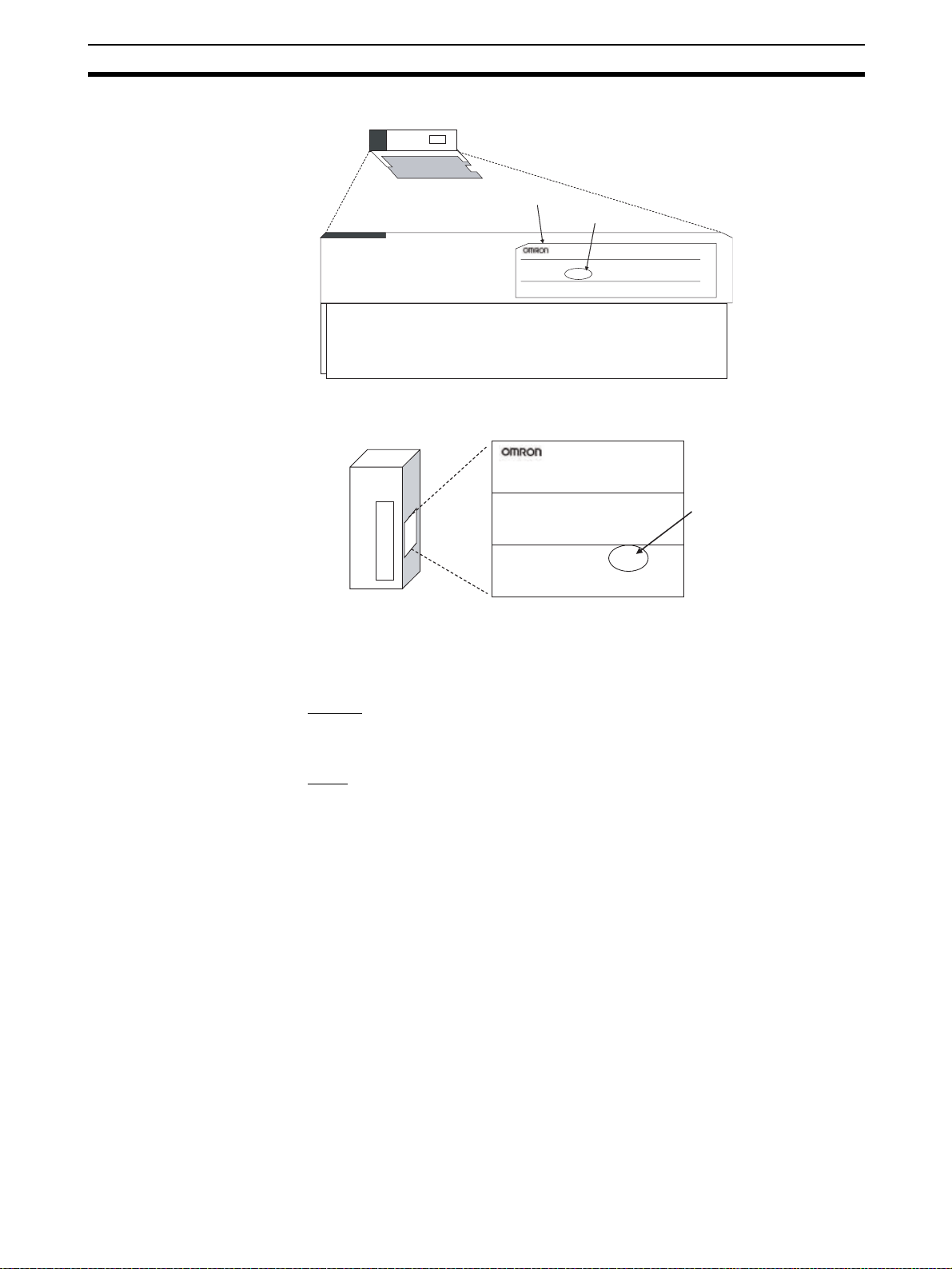
Unit Versions of CS/CJ-series Serial Communications Boards/Units 7
Example: CS1W-SCB21-V1 CS-series
Serial Communications Board
Nameplate
Unit version 1.3
CS1W-SCB21-V1
SERIAL COMMUNICATION BOARD
• Serial Communications Units
Example: CS1W-SCU21-V1 CS-series
Serial Communications Unit
Nameplate
SERIAL COMMUNICATION UNIT
:
Lot No. 051020 Ver.1.3
OMRON Corporation
CS1W-SCU21-V1
MADE IN JAPAN
Unit version 1.3
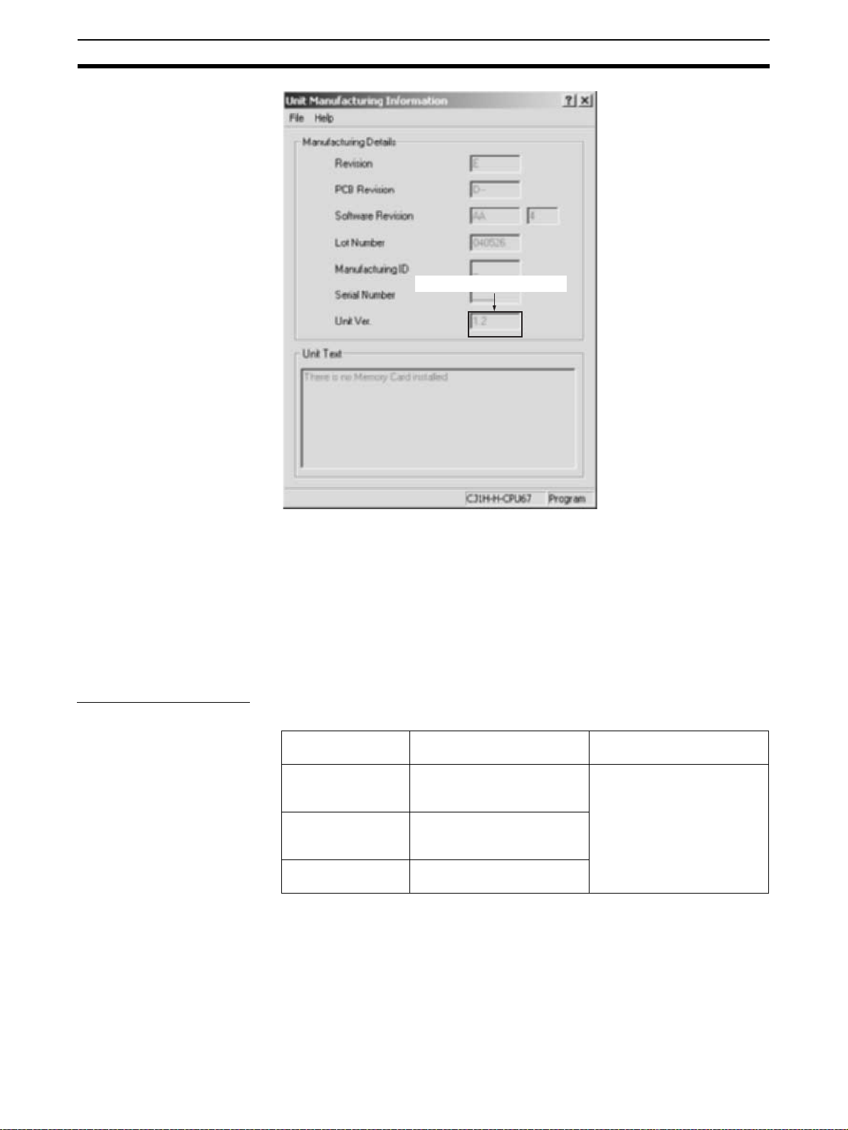
2. Confirming Unit Versions with Support Software
CX-Programmer version 5.0 can be used to confirm the unit version in the
Unit Manufacturing Information.
■Boards
In the I/O Table Window, right-click on the CPU Unit, and then select Unit
Manufacturing Information – Inner Board
■Units
1. In the I/O Table Window, right-click on the Serial Communications Unit,
and then select Unit Manufacturing Information.
2. The following Unit Manufacturing Information Dialog Box will be displayed.
Lot No. 051020 0000 Ver.1.3
OMRON Corporation
MADE IN JAPAN
xxv
Page 25
Unit Versions of CS/CJ-series Serial Communications Boards/Units 7
The unit version is displayed.
Example: In this Unit Manufacturing Information Dialog Box, unit version 1.3 is
displayed. Use this dialog box to confirm the unit version of the Serial Communications Unit that is connected online.
3. Using the Unit Version Labels
Unit version labels are provided with the product. These labels can be
attached to the front of previous Serial Communications Boards/Units to differentiate between Serial Communications Boards/Units of different unit versions.
Unit Version Notation
The unit versions are indicated in this manual as follows:
Notation in product
Ver. 1.3 or later after
the lot number
Ver.1.2 after the lot
number
Blank after the lot
number
nameplate
Notation in this manual Remarks
CS/CJ-series Serial Communications Units with unit version 1.3 or later
CS/CJ-series Serial Communications Units with unit version 1.2
Pre-Ver. 1.2 CS/CJ-series
Serial Communications Units
Information for which no particular version is specified
applies to all unit versions.
xxvi
Page 26

Unit Versions of CS/CJ-series Serial Communications Boards/Units 7
Function Support by Unit Version
Product Earlier version
CS Series Serial Communica-
tions Boards
Serial Communications Units
CJ Series Serial Communica-
tions Units
Serial gateway Not supported Supported Supported (Same as pre-
Host Link 1:1 links Not supported Supported Supported (Same as pre-
Host Link compatible
device selection
No-protocol Not supported Supported Supported (Same as pre-
Protocol
macro
Functions
Standard system protocol additions
MODBUS slave protocol added --- --- Supported
Link word specification data exchange
timing
Reception buffer processing for
PMCR(260) instruction execution
Baud rate (bps) 38,400 max. (57,600 and
(pre-ver. 1.2)
CS1W-SCB21-V1 CS1W-SCB21-V1 (Same
CS1W-SCB41-V1 CS1W-SCB41-V1 (Same
CS1W-SCU21-V1 CS1W-SCU21-V1 (Same
--- --- CS1W-SCU31-V1
CJ1W-SCU21 CJ1W-SCU21-V1 CJ1W-SCU21-V1 (Same
--- --- CJ1W-SCU31-V1
CJ1W-SCU41 CJ1W-SCU41-V1 CJ1W-SCU41-V1 (Same
Not supported Supported Supported (Same as pre-
On-request I/O refreshing only
Clearing only Select to clear or hold
115,200 not supported)
Not supported Supported Supported (Same as pre-
Unit version 1.2 Unit version 1.3
CS1W-SCB21-V1 (Same
as pre-ver. 1.2)
as pre-ver. 1.2)
as pre-ver. 1.2)
On-request I/O refreshing
Continuous I/O refreshing
contents.
57,600 supported. 57,600 supported. (Same
as pre-ver. 1.2)
CS1W-SCB41-V1 (Same
as pre-ver. 1.2)
CS1W-SCU21-V1 (Same
as pre-ver. 1.2)
as pre-ver. 1.2)
as pre-ver. 1.2)
ver. 1.2)
ver. 1.2)
ver. 1.2)
ver. 1.2)
On-request I/O refreshing
Continuous I/O refreshing
(Same as pre-ver. 1.2)
Select to clear or hold contents. (Same as pre-ver.
1.2)
as pre-ver. 1.2)
ver. 1.2)
Note Make sure that a CS/CJ-series CPU Unit with unit version 3.0 or later is used
when using no-protocol mode.
Unit Versions and Manufacturing Dates/Lot Numbers
Classification Type Model May 2004 June 2003 December 2005
Inner Boards Serial Communica-
CPU Bus Units Serial Communica-
CPU Unit Support Software
tions Boards
tions Units
CX-Programmer WS02-CXPC1-JV@ Ver. 4.0 or earlier Ver. 5.0 Version 6.1
CS1W-SCB21-V1 Pre-Ver. 1.2 Unit version 1.2
CS1W-SCB41-V1
CS1W-SCU21-V1 Pre-Ver. 1.2 Unit version 1.2
CS1W-SCU21-V1
CS1W-SCU41-V1
CS1W-SCU31-V1 --- --- Unit version 1.3
CJ1W-SCU31-V1 --- ---
(Lot No.: 040617
and later)
(Lot No.: 040617
and later)
Unit version 1.3
Unit version 1.3
(Available April,
2006)
xxvii
Page 27

Functions Added in the Unit Version 1.3 Upgrade 8
8 Functions Added in the Unit Version 1.3 Upgrade
Functions Added in Version Upgrade
The following table provides a comparison between the functions provided in
the upgrade to unit version 1.3 or later of CS1W-SCB@@-V1 Serial Communications Boards and CS1W-SCU@@-V1, CJ1W-SCU@@-V1 Serial Communications Units, and the functionality of earlier versions.
Item Previous unit versions Unit version 1.3 and later
Serial communications mode
Modbus-RTU slave mode Not supported Supported
9 Functions Added in the Unit Version 1.2 Upgrade
Upgraded Models
The model numbers of CS-series Serial Communications Units/Boards have
not changed. A “-V1” suffix has been added to the model numbers of CJseries Serial Communications Units with the unit version 1.2 upgrade, as
shown in the following table.
PLC Product Specifications Model Model number
CS
Series
CJ
Series
Serial Communications
Boards
Serial Communications
Units
Serial Communications
Units
RS-232C
RS-232C × 1
RS-232C
RS-422A/485
1
RS-232C
RS-232C × 1
RS-232C × 1,
RS-232C × 1
RS-232C
RS-422A/485
1
CS1W-SCB21-V1 → Same
× 1,
CS1W-SCB41-V1 → Same
× 1,
×
CS1W-SCU21-V1 → Same
× 1,
CJ1W-SCU21 → CJ1W-SCU21-V1
CJ1W-SCU41 → CJ1W-SCU41-V1
× 1,
×
after upgrade to
unit version 1.2
xxviii
Page 28

Functions Added in the Unit Version 1.2 Upgrade 9
Functions Added in Version Upgrade
The following table provides a comparison between the functions provided in
the upgrade to unit version 1.2 or later of CS1W-SCB@@-V1 Serial Communications Boards and CS1W-SCU@@-V1, CJ1W-SCU@@-V1 Serial Communications Units, and the functionality of earlier versions.
Serial communications
mode
Item Earlier versions
Serial Gateway Not supported Supported
Host Link 1:1 protocol Not supported (1:N
Host Link
compatible
device selection
No-protocol Not supported Supported, but only when using a CS/CJ-series
(pre-Ver.1.2)
Host Links only)
Not supported (not
completely compatible with C-series
Host Link and CVM1/
CV-series Host Link)
The received FINS command can be converted
into serial communications protocol and then converted into either of the following protocols (using
the Serial Gateway mode).
• CompoWay/F
•Modbus-RTU
• Modbus-ASCII
• Host Link FINS (This protocol can be used to
make the PLC function as the Host Link Master.)
The Serial Gateway can also be used in protocol
macro mode. This option enables, for example, programming or monitoring of a serially connected
PLC from a CX-Programmer that is connected to
the PLC during execution of protocol macros (e.g.,
Host Link Master).
Supported
This protocol functions the same as the 1:1 Host
Link supported by the earlier C200H, C1000H, and
C2000H Series, thereby enabling the use of host
computer programs for 1:1 Host LInks created
using these earlier PLCs.
Note: CS/CJ-series, C200HS/HX/HG/HE(-Z),
@, CQM1@, and CVM1/CV Series all support
CPM
1:N Host Links only. C200H and C500 Host LInk
Units support both 1:1 and 1:N Host Links.
The compatible device mode enables full compatibility of Host Link functions (see note) with C-series
Host Link and CVM1/CV-series Host Link.
Note: E.g., differences in specifications for delimiter
words in response frame data
CPU Unit with unit version 3.0 or later.
(The no-protocol mode that was previously possible only at the built-in RS-232C port of CPU Unit is
now available for the Serial Communications
Boards and Units.)
This protocol is mainly used for communications
with devices that perform input or output only, such
as bar code readers and printers.
This mode enables no-protocol communications
even if the CPU Unit’s built-in RS-232C port is
being used for another application.
Unit version 1.2 or later
xxix
Page 29

Functions Added in the Unit Version 1.2 Upgrade 9
Enhanced
protocol
macro functions
Standard system protocol
Item Earlier versions
Link word specification data
exchange timing
Reception buffer processing
for PMCR(260) instruction
execution (immediately
before communications
sequence execution)
Baud rate for protocol macro
mode
Host Link C-mode Command
Master
Host Link FINS Command
Master
(pre-Ver.1.2)
On-request I/O
refreshing only
(request to refresh
sent to CPU Unit at
every send/receive
command execution,
and data exchanged
during I/O refresh)
In this method, after
the send command is
executed, a delay
occurs before the
actual message is
sent.
Clearing to zero only Select to clear or hold the contents of the reception
38,400 bps max.
(57,600 bps not supported)
None (protocols must
be created using CXProtocol)
Unit version 1.2 or later
Continuous I/O refreshing (selected in DM Area
settings) is supported in addition to the on-request
I/O refreshing available in earlier models.
Continuous I/O refreshing is performed from the
CPU Unit during protocol macro execution, regardless of requests from the Board/Unit, and data in
the Board/Unit is accessed during send/receive
command execution. When the send command is
executed with this method, the actual message can
be sent immediately.
buffer during full-duplex communications (set in the
allocation DM Area).
This enables the data in the reception buffer
received in the previous communications sequence
to be held after switching the communications
sequence during full-duplex communications.
57,600 bps supported (115,200 bps not supported)
Provided
A Host Link Master can
be used to easily access
the Host Link slave PLC
(e.g., A PLC slave on a
moving body can be
accessed via a WMseries Wireless Modem
in a Host Link.)
Host Link C-mode commands can be used to
access a C-series or CS/
CJ-series PLC slave.
Host Link FINS commands can be used to
access a CS/CJ-series
or CVM1/CV-series PLC
slave.
This protocol can also
be used to access slave
PLCs on the network.
xxx
Mitsubishi Computer Link
Master (A-compatible, 1C
frame, model 1)
CompoWay/F Master --- Communications sequences with different send
Provided
Computer Link commands can be used to access a
Mitsubishi PLC (Sequencer CPU Module) slave.
and receive protocols are provided by using send/
receive commands with ASCII conversion.
The communications sequences have been
expanded to include CompoWay/F commands
such as VARIABLE AREA READ/WRITE and
OPERATING INSTRUCTIONS.
Page 30

SECTION 1
Introduction
This section introduces the hardware and software functions of the Serial Communications Boards and the Serial
Communications Units, including the communications modes, system configurations, and specifications.
1-1 Using this Manual . . . . . . . . . . . . . . . . . . . . . . . . . . . . . . . . . . . . . . . . . . . . . . 2
1-2 Overview. . . . . . . . . . . . . . . . . . . . . . . . . . . . . . . . . . . . . . . . . . . . . . . . . . . . . 3
1-2-1 Serial Communications Boards . . . . . . . . . . . . . . . . . . . . . . . . . . . . 3
1-2-2 Serial Communications Units . . . . . . . . . . . . . . . . . . . . . . . . . . . . . . 4
1-3 Protocol Overview. . . . . . . . . . . . . . . . . . . . . . . . . . . . . . . . . . . . . . . . . . . . . . 7
1-3-1 Host Link Mode . . . . . . . . . . . . . . . . . . . . . . . . . . . . . . . . . . . . . . . . 8
1-3-2 Protocol Macros . . . . . . . . . . . . . . . . . . . . . . . . . . . . . . . . . . . . . . . . 9
1-3-3 1:N NT Links . . . . . . . . . . . . . . . . . . . . . . . . . . . . . . . . . . . . . . . . . . 10
1-3-4 Loopback Test. . . . . . . . . . . . . . . . . . . . . . . . . . . . . . . . . . . . . . . . . . 11
1-3-5 Serial Gateway Mode . . . . . . . . . . . . . . . . . . . . . . . . . . . . . . . . . . . . 11
1-3-6 No-protocol Mode . . . . . . . . . . . . . . . . . . . . . . . . . . . . . . . . . . . . . . 11
1-3-7 Modbus-RTU Slave Mode . . . . . . . . . . . . . . . . . . . . . . . . . . . . . . . . 12
1-4 Features . . . . . . . . . . . . . . . . . . . . . . . . . . . . . . . . . . . . . . . . . . . . . . . . . . . . . . 12
1-4-1 Serial Communications Boards and Units . . . . . . . . . . . . . . . . . . . . 12
1-4-2 Protocols . . . . . . . . . . . . . . . . . . . . . . . . . . . . . . . . . . . . . . . . . . . . . . 12
1-5 System Configurations . . . . . . . . . . . . . . . . . . . . . . . . . . . . . . . . . . . . . . . . . . 16
1-6 Specifications . . . . . . . . . . . . . . . . . . . . . . . . . . . . . . . . . . . . . . . . . . . . . . . . . 23
1-6-1 Serial Communications Boards and Unit . . . . . . . . . . . . . . . . . . . . . 23
1-6-2 General Specifications . . . . . . . . . . . . . . . . . . . . . . . . . . . . . . . . . . . 25
1-6-3 Protocol Specifications . . . . . . . . . . . . . . . . . . . . . . . . . . . . . . . . . . . 26
1-7 Comparison to Previous Products . . . . . . . . . . . . . . . . . . . . . . . . . . . . . . . . . . 35
1-8 Selecting the Serial Communications Mode. . . . . . . . . . . . . . . . . . . . . . . . . . 41
1-9 Basic Operating Procedure . . . . . . . . . . . . . . . . . . . . . . . . . . . . . . . . . . . . . . . 42
1-9-1 Overview. . . . . . . . . . . . . . . . . . . . . . . . . . . . . . . . . . . . . . . . . . . . . . 42
1-9-2 Explanation of Procedure . . . . . . . . . . . . . . . . . . . . . . . . . . . . . . . . . 43
1
Page 31

Using this Manual Section 1-1
1-1 Using this Manual
This manual is structured to provide information on Host Link, protocol macro,
and 1:N NT link communications in functional units, as would be required in
actual applications. You should read Section 1 Introduction first, and then read
information in the rest of the manual and related manuals as required by your
specific application.
Information Section or Manual
Overview and appearance of the Serial Communications Boards and Serial Communications Unit
Overview, features, and specifications of serial
communications
Basic procedures and operations 1-9 Basic Operating Procedure
Selecting serial communications modes 1-8 Selecting the Serial Communications Mode
System configurations for serial communications
modes
Memory Area allocations to the Serial Communica-
tions Boards and Serial Communications Unit
Installing and wiring the Serial Communications
Boards and Serial Communications Unit
Memory Area allocations to individual serial communications modes
Communications timing for slave-initiated Host Link
communications
Ladder diagram programming in protocol macros 5-4 Using Protocol Macros
Loopback tests for ports Section 10 Loopback Test
Changing the communications port settings during
operation
Troubleshooting and maintenance Section 11 Troubleshooting and Maintenance
The contents of standard system protocols and
connection methods to OMRON components
Details on Host Link communications (including
ladder diagram programming for slave-initiated
communications)
Details on C-mode commands
Details on FINS commands
Details on the protocol macro function SYSMAC WS02-PSTC1-E
1-2 Overview
2-1 Component Names and Functions
1-3 Protocol Overview
1-4 Features
1-6 Specifications
4-1 Host Link Communications
5-1 Overview of the Protocol Macro Functions
8-1 Overview of 1:N NT Links
1-5 System Configurations
2-2 Data Exchange with the CPU Unit
2-3 I/O Memory Allocations
Section 3 Installation and Wiring
4-2, 5-2, and 8-2 Setup Area Allocations
4-3, 5-3, and 8-3 Auxiliary Area and CIO Area Allo-
cations
4-4 Communications Timing
Appendix R Changing Communications Port
Settings Using STUP(237)
Appendix A to Appendix N
SYSMAC CS/CJ-series
CS1G/H-CPU@@-E, CS1W-SCB21/41,
CS1W-SCU21 Communications Commands
Reference Manual (W342)
CX-Protocol Operation Manual (W344)
2
Page 32

Overview Section 1-2
1-2 Overview
This section gives an overview of the Serial Communications Boards and the
Serial Communications Unit.
1-2-1 Serial Communications Boards
Serial Communications Boards are Inner Boards for the CS-series PLCs. One
Board can be installed in the Inner Board slot of a CPU Unit. Two serial ports
are provided for connecting host computers, Programmable Terminals (PTs),
general-purpose external devices, and Programming Devices (excluding Programming Consoles). This makes it possible to easily increase the number of
serial ports for a CS-series PLC.
Serial Communications
Board
Inner Board slot
Models The following two models are available:
CS1W-SCB21-V1
Two RS-232C ports
RS-232C port
RS-232C port
CS1W-SCB41-V1
One RS-232C port + one RS-422A/485 port
RS-232C port
RS-422A/485 port
Connectable Devices The following serial communications modes are supported by the Serial Com-
munications Unit: Host Link (SYSMAC WAY) (see note 1), protocol macro,
1:N NT Link (see note 2), no-protocol (see note 1), Modbus-RTU slave (see
note 3), and loopback test modes. The devices shown in the following diagram
can be connected.
Programming
General-purpose
external device
Programmable
Terminal (PT)
Device (excluding
Programming
Console)
Host computer
Serial Communications Board
CPU Unit
General-purpose
external device
Programmable
Terminal (PT)
Programming
Device (excluding
Programming
Console)
Host computer
3
Page 33

Overview Section 1-2
Note (1) The Host Link 1:1 and no-protocol modes are supported by unit version
1.2 or later.
(2) Only a 1:N NT Link is supported. A 1:1 NT Link is not supported.
(3) The Modbus-RTU slave mode is supported by unit version 1.3 or later.
A serial communications mode for the Serial Gateway is also provided,
enabling connection with the following devices.
Modbus-RTU-compatible
device (e.g., Inverter)
Modbus-ASCII-compatible
CompoWay/Fcompatible
OMRON
component
device (e.g., Servo)
PLC (Host Link)
FINS message
Serial Communications Board
with unit version
1.2 or later
Protocol
conversion
Protocol
conversion
CPU Unit
FINS message
CompoWay/Fcompatible
OMRON
component
Modbus-RTU-compatible
device (e.g., Inverter)
Modbus-ASCII-compatible
device (e.g., Servo)
1-2-2 Serial Communications Units
The Serial Communications Units are CPU Bus Unit. One or more Units can
be mounted to the CPU Unit or a CS/CJ Expansion Rack. A total of up to 16
CPU Bus Units can be controlled by one CPU Unit. The CS-series Serial
Communications Unit must be used for a CS-series PLC and a CJ-series
Serial Communications Unit must be used for a CJ-series PLC.
Two serial ports are provided for connecting host computers, Programmable
Terminals (PTs), general-purpose external devices, and Programming
Devices (excluding Programming Console). This makes it possible to easily
increase the number of serial ports for the CS/CJ-series PLC.
CS Series
Serial Communications Unit
PLC (Host Link)
4
Page 34

Overview Section 1-2
t
t
CJ Series
CS1W-SCU21-V1
(Two RS-232C ports)
RS-232C port
RS-232C port
P
A
2
0
5
R
P
O
W
E
R
L1
AC100-240V
INPUT
L2/N
RUN
OUTPUT
AC240V
DC24V
CS1W-SCU31-V1
(Two RS-422A/485 ports)
Serial Communications Unit
SYSMAC
R
U
N
E
R
R
/A
L
M
CJ1G-CPU44
IN
H
P
R
O
G
R
A
M
M
A
B
L
E
P
R
P
H
L
C
O
N
T
R
O
L
L
E
R
C
O
M
M
O
P
E
N
M
C
P
W
R
B
U
S
Y
P
E
R
IP
H
E
R
A
L
P
O
R
T
RS-422A/485 por
RS-422A/485 por
SCU41
RUN
ERC
SD1
RD1
TER1
RDY
ERH
SD2
RD2
TERM
OFF
ON
UNIT
5
4
6
3
7
2
8
1
9
NO.
0
A
F
B
E
C
D
WIRE
2
4
PORT1
(RS422
/485)
PORT2
CJ1W-SCU21-V1
(Two RS-232C ports)
CJ1W-SCU41-V1
(One RS-232C and One RS422A/485 Port)
RS-232C port
RS-232C port
RS-422A/485 port
RS-232C port
CJ1W-SCU31-V1
(Two RS-422A/485 ports)
RS-422A/485 port
RS-422A/485 port
Connectable Devices The following serial communications modes are supported by the Serial Com-
munications Boards: Host Link (SYSMAC WAY) (see note 1), protocol macro,
1:N NT Link (see note 2), no-protocol (see note 1), Modbus-RTU slave (see
note 3), and loopback test modes. The devices shown in the following diagram
can be connected.
5
Page 35

Overview Section 1-2
)
Programming
General-purpose
external device
Programmable
Terminal (PT)
Device (excluding
Programming
Console)
Host computer
Serial Communications Unit
CS/CJ-series PLC
General-purpose
external device
Programmable
Terminal (PT)
Programming
Device (excluding
Programming
Console
Host computer
Note (1) The Host Link 1:1 and no-protocol modes are supported by unit version
1.2 or later.
(2) Only a 1:N NT Link is supported. A 1:1 NT Link is not supported.
(3) The Modbus-RTU slave mode is supported by unit version 1.3 or later.
A serial communications mode for the Serial Gateway is also provided,
enabling connection with the following devices.
Modbus-RTU-compatible
device (e.g., Inverter)
Modbus-ASCII-compatible
CompoWay/Fcompatible
OMRON
component
device (e.g., Servo)
PLC (Host Link)
FINS message
Serial Communications Unit with
unit version 1.2 or
later
Protocol
conversion
Protocol
conversion
CPU Unit
FINS message
Functions Added in the
“-V1” Upgrade
6
CompoWay/Fcompatible
OMRON
component
Modbus-RTU-compatible
device (e.g., Inverter)
Modbus-ASCII-compatible
device (e.g., Servo)
PLC (Host Link)
The CS1W-SCB21-V1 and CS1W-SCB41-V1 Serial Communications Boards
and CS1W-SCU21-V1 Serial Communications Unit* were upgraded to support the Simple Backup Function in the “-V1” upgrade.
Simple Backup Function
The CPU Unit’s Simple Backup Function can be used to automatically
backup, restore, and compare the Protocol Macro data (both standard system
protocol and user-set protocol data) in the Serial Communications Board or
Unit’s flash memory with the data in the CPU Unit’s Memory Card. The Protocol Macro data is backed up, restored, or compared along with all of the data
in the CPU Unit. (The Simple Backup Function can be used with CS1-H, CJ1H, and CJ1M CPU Units only.)
Page 36

Protocol Overview Section 1-3
Note *The CS-series Serial Communications Boards/Units without the “-V1” suffix
do not support this Simple Backup Function, but the CJ1W-SCU21/41 does
support this function even though the model number lacks the “-V1” suffix.
1-3 Protocol Overview
A Serial Communications Board is an Inner Board for CS-series CPU Units
that provides RS-232C and/or RS-422A/485 serial ports. An Inner Board is an
option and is installed in the CPU Unit.
A Serial Communications Unit is a CPU Bus Unit that provides two RS-232C
serial ports or one RS-232C and one RS-422A/485 port. The following eight
serial communications modes can be used as required for each serial port.
• Host Link: For connections between host computers and PLCs
• Protocol macro: For communications between PLCs and general-purpose
external devices
• 1:N NT Link: For communications between PLCs and Programmable
Terminals (PTs)
• Loopback test: For testing the communications ports
•Serial Gateway
• No-protocol
• 1:1 Host Link
• Modbus-RTU slave mode
Note (1) The Serial Gateway can also be executed in protocol macro mode.
(2) Modbus-ASCII mode is not supported.
PLC
Series
CS Serial
CJ Serial
--- Device to be connected Host computer
Supporting unit versions All unit versions Unit version 1.2 or later Unit version 1.3
Product Model
Communications
Boards
Serial
Communications Unit
Communications Unit
number
CS1WSCB21-V1
CS1WSCB41-V1
CS1WSCU21-V1
CS1WSCU31-V1
CJ1WSCU21-V1
CJ1WSCU31-V1
CJ1WSCU41-V1
Serial ports Serial communications mode
Host Link Protocol
RS-232C OK OK OK OK OKOKOKOKOK
RS-232C OK OK OK OK OKOKOKOKOK
RS-232C OK OK OK OK OKOKOKOKOK
RS-422A/485 OK (See note 1.) OK OK OK OK OK OK OK OK
RS-232C OK OK OK OK OKOKOKOKOK
RS-232C OK OK OK OK OKOKOKOKOK
RS-422A/485 OK (See note 1.) OK OK OK OK OK OK OK OK
RS-422A/485 OK (See note 1.) OK OK OK OK OK OK OK OK
RS-232C OK OK OK OK OKOKOKOKOK
RS-232C OK OK OK OK OKOKOKOKOK
RS-422A/485 OK (See note 1.) OK OK OK OK OK OK OK OK
RS-422A/485 OK (See note 1.) OK OK OK OK OK OK OK OK
RS-422A/485 OK (See note 1.) OK OK OK OK OK OK OK OK
RS-232C OK OK OK OK OKOKOKOKOK
or Programming
Device
macro
Generalpurpose
external
device
1:N NT Link
(See note 2.)
PT None Depends on the
Loop-
back
test
Serial
Serial
Gate-
Gate-
way
way in
proto-
col
macro
mode
protocol used at
the conversion
destination
No-
proto-
col
(See
note
3.)
Generalpurpose
external
device
1:1
Mod-
Host
bus-
Link
RTU
slave
Host Link computer
or later
Note 1. A 4-wire connection must be used when using Host Link communications
for an RS-422A/485 connector.
7
Page 37

Protocol Overview Section 1-3
2. A 1:1 NT Link is not supported.
3. No-protocol mode can be used with CS/CJ-series CPU Units with Unit Ver.
3.0 or later only.
A connection example for each serial communications mode is shown in the
following sections for a Serial Communications Unit. The examples apply
equally as well to the Serial Communications Boards.
1-3-1 Host Link Mode
In Host Link mode, C-mode commands (Host Link commands) or FINS commands can be sent from a host computer to read or write I/O memory in the
PLC or to control the PLC’s operating modes. The host computer can be a
personal computer or a Programmable Terminal. The FINS commands are
sent with other data, such a Host Link header and terminator.
In Host Link mode, SEND(090), RECV(098), and CMND(490) instructions can
be used to send FINS commands from PLC to the host computer to read
data, write data, or perform other operations. This is called slave-initiated
communications or unsolicited communications. The FINS commands are
sent with other data, such a Host Link header and terminator.
Note 1. FINS commands can be sent across up to three different networks (count-
ing the local network) to a PLC on a remote network or to a host computer
connected to a PLC on a remote network.
2. Programming Devices can also be connected in Host Link mode.
Sending C-mode Commands
Sending FINS Commands
Host Link
FINS
command
Host Link
header
Host Link
terminator
Host Link
C-mode (Host Link)
command
FINS commands can also be sent to
PLCs on remote networks.
Host Link
FINS
command
Host Link
header
Host Link
terminator
Remote network
(Controller Link or
Ethernet)
FINS command
8
Page 38

Protocol Overview Section 1-3
Slave-initiated Communications
Host Link
FINS
command
Host Link
terminator
Host Link
header
Slave-initiated FINS commands can also
be sent from PLCs on remote networks.
Host Link
FINS
command
Host Link
header
Host Link
terminator
Remote network
(Controller Link
or Ethernet)
Unit Ver. 1.2 or later supports the 1:1 Host Link protocol for C200H, C1000H,
and C2000H CPU Units, which enables the use of host programs for 1:1 Host
Links created for these PLCs. A Host Link-compatible device selection function is also provided for complete compatibility with the C-series Host Link and
CVM1/CV-series Host Link.
SEND(090),
RECV(098),
CMND(490)
FINS
command
SEND(090): Sends data to host computer
RECV(098): Reads data from host computer
CMND(490): Executes any FINS command
SEND(090),
RECV(098),
CMND(490)
1-3-2 Protocol Macros
Data transfer procedures (protocols) with general-purpose external devices
are created using the CX-Protocol to match the communications specifications (half-duplex or full-duplex, and start-stop synchronization) of the external
device.
These protocols are stored in the Serial Communications Boards or the Serial
Communications Unit, and enable data to be exchanged with general-purpose external devices simply by executing the PMCR(260) instruction in the
CPU Unit.
Standard system protocols for exchanging data with OMRON devices (such
as Temperature Controllers, Intelligent Signal Processors, Bar Code Readers,
and Modems) are provided as a standard feature in the Serial Communications Boards, the Serial Communications Unit, and the CX-Protocol. The CXProtocol can also be used to change the standard system protocols according
to user requirements.
PMCR(260)
Serial Communications Unit
Communications sequence
Protocol
General-purpose external device
9
Page 39

Protocol Overview Section 1-3
The following additional functions are supported for unit Ver. 1.2 or later.
• Serial Gateway can be executed during protocol macro execution.
• An new I/O refresh method is provided for constant data conversion of
link words.
• The contents of the reception buffer can be held while the PMCR(260)
instruction is executing.
• A baud rate of 57,600 bps is possible (115,200 bps is not possible).
1-3-3 1:N NT Links
A PLC can be connected to one or more Programmable Terminals (PTs)
using an RS-232C or RS-422A/485 port. The I/O memory of the PLC is allocated to the Status Control Areas and the Status Notification Areas used by
the PTs, as well as to display objects, such as touch switches, lamps, and
memory tables. This enables the status of the I/O memory in the PLC to be
controlled and monitored by operations from the PTs, without the use of a ladder diagram programming in the PLC. Up to eight PTs can be connected to a
PLC.
Note The user does not need to be aware of NT Link commands. The user only has
to allocate the PLC memory to the PTs.
Serial Communications Unit
NT Link
(Set to 1:N)
PT
Serial Communications Unit
1:N NT Link
PT
Note 1. The serial port on the PT must be set to a 1:N NT Link.
2. The Serial Communications Boards and Units do not support 1:1 NT Links.
The NT Link must be set to 1:N even if only one PT is connected. Connection is not possible to PTs that do not support 1:N NT Links.
3. The NT20S, NT600S, NT30, NT30C, NT620, NT620C, and NT625C cannot be used if the cycle time of the CPU Unit is 800 ms or longer (even if
only one of these PTs is used in a 1:N NT Link).
4. The Programming Console functions of the PT (Expansion Mode) cannot
be used when connected to Serial Communications Board or Unit ports.
They can be used only by connecting to the peripheral port or RS-232C
port on the CPU Unit.
5. Set a unique unit number for each PT connected to the same PLC. If the
same unit number is set for more than one PT, malfunctions will occur.
6. NT Link serial communications are unique and are not compatible with other serial communications modes.
10
Page 40

Protocol Overview Section 1-3
1-3-4 Loopback Test
A connector with a loopback connection is attached to the specified serial port
to perform loopback tests. Data is sent to this port, and the communications
circuit is tested by comparing the transmitted data and the data returned by
loopback.
Note This loopback test is performed inside the specified serial port. It is not a loop-
back test using the RS-232C or RS-422A/485 communications path.
Loopback test
1-3-5 Serial Gateway Mode
The received FINS message is automatically converted to either CompoWay/F, Modbus-RTU, Modbus-ASCII, or Host Link FINS, depending on the
type of message.
CompoWay/F, Modbus-RTU, and Modbus-ASCII
Serial
Communications
Unit
Serial
Gateway
CompoWay (See note.)
CompoWay-compatible
OMRON component,
Modbus-RTU-, or Modbus
ASCII-compatible device
FINS Host Link
FINS
Network
FINS
CompoWay/F (See note.)
Network
FINS
CompoWay/F (See note.)
Note: Or Modbus-RTU
Send FINS
CMND
command
CMND
commands or Modbus
ASCII commands
Send FINS command
Loopback test switch
The loopback test results
are stored.
CX-Programmer or other
Programming Device for
using CX-Server as a
communications driver
1-3-6 No-protocol Mode
No-protocol mode supports data receiving or data sending using data receive
or send commands, respectively (see note). No-protocol mode, however, can
be used only with CS/CJ-series CPU Units with unit Ver. 3.0 or later in which a
Serial Communications Board or Unit with Unit Ver. 1.2 or later is installed.
Use the no-protocol mode when the data send and receive protocols are to be
created by the user, or when connecting to devices that only receive or send
data, such as bar code readers, or printers.
Serial
Gateway
FINS
FINS
Host Link
header
Host link
terminator
FINS
Host Link
header
PLC (Host Link)
Host link terminator
11
Page 41

Fe at ur es Section 1-4
Note Serial Communications Boards send/receive data using TXD(236)/RXD(235)
instructions. Serial Communications Units send/receive data using
TXDU(256)/RXDU(255) instructions.
Serial Communications Unit
No-protocol
1-3-7 Modbus-RTU Slave Mode
Modbus-RTU slave mode enables sending Modbus-RTU commands from the
host computer to read and write PLC I/O memory.
Modbus-RTU
Modbus command
1-4 Features
This section describes the features of the Serial Communications Boards, the
Serial Communications Unit, and the protocols.
ST
Tex t
Note: Start code and end code can be specified.
General-purpose external device
Serial Communications Unit
E.g., TXDU
E.g., Execute data transmission
CR+LF
1-4-1 Serial Communications Boards and Units
Serial Communications
Boards (CS Series Only)
Serial Communications
Unit (CS/CJ Series)
A Serial Communications Board is installed as an option in a CPU Unit. Two
serial ports can thus be added without using an I/O slot.
There are two types of Serial Communications Boards: One with two RS232C ports and one with one RS-232C and one RS-422A/485 port. The RS422A/485 port can be used for a 1:N connection with general-purpose external devices without using Link Adapters to support the protocol macro function or NT Link function.
A total of up to 16 CPU Bus Units can be mounted on the CPU Rack or an
Expansion Rack. The total of 16 must include all Serial Communications Units
and all other CPU Bus Units. The PLC can thus be expanded to provide additional serial ports as required by the system.
1-4-2 Protocols
Host Link Communications
Host Link communications are supported by all CS/CJ-series CPU Units.
Serial Communications Boards and Units can be used to connect a single
PLC to more than one host computer for Host Link communications, including
slave-initiated communications. Host Link communications provide the following features.
Connect One Computer to
Multiple PLCs
An RS-422A/485 port can be used to connect one host computer to up to 32
CS/CJ-series PLCs.
12
Page 42

Fe at ur es Section 1-4
Computer Monitoring and
Control of PLCs
FINS Commands for
Complete Control
Redundant Error
Checking
Simultaneous Usage of
Both Ports
Slave-initiated
Communications
Send FINS Commands to
Remote Networks
Host Link communications enable the host computer to monitor or control
PLC operations and to read and write I/O memory in the PLCs.
In addition to C-series (Host Link) commands, FINS commands are also supported. FINS commands give you the power to control CS/CJ-series PLC
functionality.
Both vertical and horizontal (FCS) parity checks are performed on communications data to achieve essentially error-free communications. Combining
error checking and retry processing goes one step further to eliminate nearly
all the effects of communications problems.
Each Serial Communications Board and Unit provides two serial ports that
can be used simultaneously to connect to two different host computers. A total
of up to 16 CPU Bus Units, including the Serial Communications Units, can be
mounted to one PLC. If all 16 CPU Bus Units are Serial Communications
Units, then up to 32 ports can be added.
Communications can be performed either by sending a command from a host
computer and having the PLC return a response, or by sending a command
from a PLC and having the computer send a response. Starting communications from a slave is called unsolicited communications, and is made possible
through the SEND(090), RECV(098), and CMND(490) instructions. These
can be used to send FINS commands to a host computer connected locally or
to a host computer connected to a remote network up to three networks away
(counting the local network).
A FINS command contained within a Host Link header and terminator can be
sent using Host Link communications to PLCs connected not only on Host
Link networks, but also other interconnected remote networks up to three networks away (counting the local network). Various types of networks can exist
between the source of the command and the destination of the command.
Send FINS Commands to
Computers Connected to
Remote PLCs
Host Link
Controller Link Network
Bridge
Controller Link Network
Ethernet Network
Gateway
A FINS command contained within a Host Link header and terminator can be
sent using Host Link communications to a host computer connected to a PLC
on a remote network up to three networks away (counting the local network,
but not counting the final Host Link connection). Various types of networks
can exist between the PLC sending the command and the destination of the
command.
13
Page 43

Fe at ur es Section 1-4
Host Link
Controller Link Network
Bridge
Controller Link Network
Ethernet Network
Gateway
SEND(090),
RECV(098),
CMND(490)
Protocol Macros
The main features of the protocol macro functions are described below. For
details, refer to the CX-Protocol Operation Manual (W344).
Wide Range of
Communications
Protocols
Send Frames and Receive
Frames Matching
Specifications
Communications-related
Functions
Send/Receive Monitoring Receive wait monitoring, receive completion monitoring, and send completion
Retry Processing Send/receive retry processing can be automatically executed when an error
PLC Read/Write Variables
in Send Frames and
Receive Frames
Switch 1:N
Communications or the
Data Write Destinations
Using Repeat Processing
PLC Interrupts During
Data Reception
Next Process Switching
According to Receive Data
New Error Check Codes LRC2 (two’s complement of LRC), and SUM1 (one’s complement of SUM)
Step Queuing for Sync
Signal from the PLC
Half-duplex or Full-duplex
Transmissions
Communications are possible with virtually any general-purpose external
device, provided it has an RS-232C or RS-422A/485 port, supports halfduplex or full-duplex communications, and supports start-stop synchronization.
Send frames (command + data and other send frames) and receive frames
(response and other frames) can be created and registered according to the
communications frame specifications of the external device.
Error check code calculations, frame length calculations during sending, and
⇔Hexadecimal conversion of numeric data are supported.
ASCII
monitoring are supported. If monitoring times are exceeded, send/receive can
either be terminated, or retry processing can be performed.
occurs, simply by setting the number of retries.
Variables for reading PLC memory can be included in the actual send frames.
These can be used as destination addresses or data when reading PLC data
while sending. Variables for writing to PLC memory can be also included in
the actual receive frames. These can be used to write the contents of destination addresses or data to the PLC during reception.
Repeat processing (repeat counters) for send/receive processing can be
specified in communications sequences. This enables the same data to be
sent by switching destination addresses during communications 1:N (N = 32
max. due to restrictions in the physical layer) or by switching the PLC memory
write destination addresses during data reception.
An interrupt can be created in the PLC’s CPU Unit during data reception, and
an interrupt program can be executed in the CPU Unit. (The PLC interrupt
function is supported only for the Serial Communications Boards. This function cannot be used with Serial Communications Units.)
The contents of up to 15 set of expected receive data can be compared with
the receive data to determine the next process.
have been added to the error check codes.
At any step of the communications sequence, the next process can be made
to wait until a sync signal from the PLC’s CPU Unit has been input. This
enables processing, such as data manipulations, to be performed in the CPU
Unit during the communications sequence.
With the conventional protocol macro functions, only half-duplex transmissions were possible. With half-duplex mode, the reception buffer is cleared
14
Page 44

Fe at ur es Section 1-4
immediately after the send operation is completed. Therefore, if there was a
rapid response from the remote device, for example, the data received
between data sending and the completion of the send operation could not be
accessed as receive data by the next receive operation.
Support for the full-duplex transmissions enables all the data received in a
sequence to be accessed. Data can also be received from a remote device
while sending.
Note Full-duplex transmissions can be used with either RS-232C or RS-422A/485
as long as 1:1, 4-wire connections are used. Full-duplex transmissions cannot
be used with 1:N connections or 2-wire connections.
Clear Reception Buffer at
Any Time
Control ER Signal at Any
Time
With full-duplex mode, the reception buffer is cleared only immediately before
a communications sequence is executed. When a reception or other fault
occurs, the receive data can be cleared at any time using the reception buffer
clear (FLUSH) command.
With a connection to a modem, the ER signal is used to show the communications enabled status of a Serial Communications Board or Unit (Data Terminal
Equipment (DTE)). In conventional operations, the ER signal could be turned
ON only while a communications sequence was being executed.
Improving this function has enabled the ER signal to be turned ON or OFF at
any time during a communications sequence. This enables modem connections and disconnections to be performed by a protocol macro.
The ER signal can also be kept ON, even after a communications sequence
has been completed. In this case, the ER signal remains ON, even after it has
been switched to a different serial communications mode (for example, Host
Link). This function enables remote programming and monitoring to be performed using remote Programming Devices, by switching to the Host Link
mode with the STUP(237) instruction once the connection has been made
with the modem.
15
Page 45

System Configurations Section 1-5
1-5 System Configurations
This section explains the system configuration supported by each serial communications mode.
Host Link Communications
PLC:
Computer
1:1
Por t:
RS-232C
Connection to Serial Communications Board.
Connection configuration Required
CS1W-SCB21-V1Port 1 or 2 Host computer
Note 1.
CS1W-SCB41-V1Por t 1
NT-AL001-E
Converting
Link Adapter
Note 3.
Note 2.
NT-AL001-E NT-AL001-E
Note 3.
5-V power
supply
devices
Connected
serial
port/Remarks
Converts
between
RS-232C and
RS-422A/485
For NT-AL001-E
Link Adapter
Possible com-
mand flow
to PLC:
C-mode or
FINS
commands
PLC to Host
computer:
FINS
commands only
1:1
Por t:
RS-422A/
485
Resistance ON,
5-V power
Connection to Serial Communications Unit.
Resistance ON
Note 1.
CS1W-SCU21-V1Por t 1 or 2
CJ1W-SCU21-V1Por t 1 or 2
CJ1W-SCU41-V1Por t 2
Note 3.
Note 2.
NT-AL001-E NT-AL001-E
Resistance ON,
5-V power
Resistance ON
Note 3.
NT-AL001-E
Converting
Link Adapter
5-V power
supply
Converts
between
RS-232C and
RS-422A/485
For NT-AL001-E
Link Adapter
Connection to Serial Communications Board CS1W-SCB41-V1Port 2 Host computer
Note 3.
NT-AL001-E
Resistance ON,
5-V power
Note 2.
Resistance ON
NT-AL001-E
Converting
Link Adapter
5-V power
supply
RS-232C
RS422A/485
For NT-AL001-E
Link Adapter
Connection to Serial Communications Unit CS1W-SCU31-V1Por t 1 or 2
Note 3.
NT-AL001-E
Resistance ON,
5-V power
Note 2.
Resistance ON
CJ1W-SCU31-V1Por t 1 or 2
CJ1W-SCU41-V1Por t 1
NT-AL001-E
Converting
RS-232C
RS422A/485
⇔
⇔
to PLC
(4-wire only):
C-mode or
FINS
commands
PLC to Host
computer
(4-wire only):
FINS
commands only
Link Adapter
5-V power
supply
For NT-AL001-E
Link Adapter
16
Page 46

System Configurations Section 1-5
PLC:
Computer
1:N
Por t:
RS-232C
1:N
Por t:
RS-422A/
485
Connection configuration Required
devices
Connected
serial
Possible com-
mand flow
port/Remarks
Connection to Serial Communications Board.
Note 3. Note 2.
NT-AL001-E
Resistance ON,
5-V power
Resistance
ON
Connection to Serial Communications Unit.
Note 3. Note 2.
CS1W-SCB21-V1Port 1 or 2 Host computer
to PLC
CS1W-SCB41-V1Por t 1
NT-AL001-E
Converting
Link Adapter
Converts
between
RS-232C and
RS-422A/485
5-V power
supply
For NT-AL001-E
Link Adapter
(RS-422A/485
section: 4-wire):
C-mode or
FINS
commands
PLC to Host
computer:
Commands
cannot be sent.
CS1W-SCU21-V1Por t 1 or 2
CJ1W-SCU21-V1Por t 1 or 2
NT-AL001-E
Resistance ON,
5-V power
Resistance
ON
CJ1W-SCU41-V1Por t 2
NT-AL001-E
Converting
Link Adapter
Converts
between
RS-232C and
RS-422A/485
5-V power
supply
For NT-AL001-E
Link Adapter
Connection to Serial Communications Board CS1W-SCB41-V1Port 2 Host computer
Note 3.
Resistance ON,
5-V power
Note 4.
Note 2.
Resistance ON
NT-AL001-E
Converting
Link Adapter
5-V power
supply
RS-232C
RS422A/485
For NT-AL001-E
Link Adapter
Connection to Serial Communications Unit CS1W-SCU31-V1Por t 1 or 2
Note 3.
CJ1W-SCU31-V1Por t 1 or 2
⇔
to PLC
(4-wire only):
C-mode or
FINS
commands
PLC to Host
computer:
Commands
cannot be sent.
Resistance ON,
5-V power
Note 4.
Note 2.
Resistance ON
CJ1W-SCU41-V1Por t 1
NT-AL001-E
Converting
RS-232C
RS422A/485
Link Adapter
5-V power
supply
For NT-AL001-E
Link Adapter
⇔
17
Page 47

System Configurations Section 1-5
PLC:
Computer
Host
computer
to
Network
PLCs, 1:N
Connection configuration Required
Connection to Serial Communications Board or Serial
Communications Unit
Controller Link or
Ethernet network
Communications can be sent across three different networks (counting the local network, but not including a
Host Link connection). Routing tables must be set in the PLCs.
Host Link
Network 1
Gateway or bridge
devices
Any Serial
Communications Board or
Unit
Communications Unit:
Controller Link
Unit or Ethernet Unit
Connected
serial
port/Remarks
Port 1 or 2 Host computer
or
Network 3
Possible com-
mand flow
to PLC:
FINS
commands only
PLC to Host
computer:
FINS
commands only
(RS-422A/485:
4-wire only)
Network 2
Gateway
Note 1. The maximum cable length for RS-232C is 15 m. The RS-232C standard,
however, does not cover baud rates above 19.2 Kbps. Refer to the manual
for the device being connected to confirm support.
2. The combined cable length for RS-422A/485 is 500 m including branch
lines.
3. The maximum cable length is limited to 2 m when an NT-AL001-E Link
Adapter is connected.
4. Branch lines must be a maximum of 10 m long.
5. Four-wire connections must be used for RS-422A/485 connections with
Host Link communications.
6. “Resistance ON” indicates that the terminating resistance must be turned
ON.
7. “5-V power” indicates that a 5-V power supply is required for the Link
Adapter. Refer to the Link Adapter manual for details. Be sure that the power supply has sufficient capacity and accuracy and wire it away from highpower lines and another sources of noise. A 5-V power supply is not required for a Link Adapter connected to a Serial Communications Board or
Unit because power is supplied from pin 6 of the connector.
8. The maximum baud rate of the NT-AL001-E Link Adapter is 64 Kbps. Do
not use 115.2 Kbps when a Link Adapter is connected.
18
Page 48

System Configurations Section 1-5
Protocol Macros, Serial Gateway, No-protocol, or Modbus-RTU Slave
PLC:
External
device
1:1
Por t:
RS-232C
Connection of a Serial Communications Board to a device with an
RS-232C or RS-422A/485 port.
Connection of a Serial Communications Unit to a device with an
RS-232C or RS-422A/485 port.
Connection configuration Required
devices
CS1W-SCB21-V1Por t 1 or 2
Note 1.
RS-232C
CS1W-SCB41-V1Por t 1
NT-AL001-E
RS-232C
interface
Note 2.Note 3.
NT-AL001-E
RS-232C RS-422A/485
Resistance
ON
Note 3.
NT-AL001-E
RS-232C RS-422A/485
Resistance
ON
Note 2.
Resistance
ON
NT-AL001-E
Resistance ON
5-V power
RS-232C
interface
RS-422A/485
interface
Converting Link
Adapter
5-V power
supply
CS1W-SCU21-V1Por t 1 or 2
Note 1.
RS-232C
CJ1W-SCU21-V1Por t 1 or 2
CJ1W-SCU41-V1Por t 2
RS-232C
interface
Note 2.Note 3.
NT-AL001-E
Converting Link
Adapter
NT-AL001-E
RS-232C
Resistance ON
Note 3.
RS-232C RS-422A/485
RS-422A/485
Note 2.
NT-AL001-E
Resistance ON
Resistance
ON
NT-AL001-E
Resistance ON
5-V power
RS-232C
interface
RS-422A/485
interface
5-V power
supply
Connected serial
port/Remarks
Converts between
RS-232C and
RS-422A/485
For NT-AL001-E
Link Adapter
Converts between
RS-232C and
RS-422A/485
For NT-AL001-E
Link Adapter
19
Page 49

System Configurations Section 1-5
PLC:
External
device
1:1
Por t: RS-
422A/ 485
Connection configuration Required
Connection of a Serial Communications Unit to a device with an RS232C or RS-422A/485 port
Note 2.
RS-422A/485 interface
Resistance ON
RS-232C
RS-232C interface
Resistance ON
Resistance ON
RS-422A/485
Note 2. Note 3.
NT-AL001-E
RS-422A/
Resistance ON
485
5-V power
Connection of a Serial Communications Board to a device with an RS232C or RS-422A/485 port
Note 2.
RS-422A/485 interface
Resistance ON
RS-232C
RS-232C interface
Resistance ON
Resistance ON
RS-422A/485
Note 2. Note 3.
NT-AL001-E
RS-422A/
Resistance ON
485
5-V power
devices
port/Remarks
CS1W-SCU31-V1Por t 1 or 2
CJ1W-SCU31-V1Por t 1 or 2
CJ1W-SCU41-V1Por t 1
Connected serial
NT-AL001-E
Converting Link
Adapter
5-V power
supply
Convert between
RS-232C and
RS-422A/485
For NT-AL001-E
Link Adapter
CS1W-SCB41-V1Por t 2
NT-AL001-E
Converting Link
Adapter
5-V power
supply
Convert between
RS-232C and
RS-422A/485
For NT-AL001-E
Link Adapter
20
Page 50

System Configurations Section 1-5
PLC:
External
device
1:N
Por t: RS-
232C
Connection configuration Required
Connection of a Serial Communications Board to devices with
RS-232C or RS-422A/485 ports
Note 3.
NT-AL001-E
RS-232C RS-422A/485
Resistance ON
Note 3.
RS-232C
Note 3.
NT-AL001-E
RS-232C
NT-AL001-E
Resistance
ON
Resistance
ON
RS-422A/485
B600-AL001
RS-422A/485
Note 2.
NT-AL001-E
Note 2.
Note 2.
RS-422A/485 interface
Note 4.
RS-232C
RS-232C
RS-422A/485 interface
Resistance ON
Resistance ON
RS-232C interface
devices
port/Remarks
CS1W-SCB21-V1Por t 1 or 2
CS1W-SCB41-V1Por t 1
Connected serial
NT-AL001-E
Converting Link
Adapter
B500-AL001
Link Adapter
5-V power
supply
Converts between
RS-232C and
RS-422A/485
For RS-422A/485
branching
For NT-AL001-E
Link Adapter
Resistance ON
5-V power
RS-232C
Note 3.
Connection of a Serial Communications Unit to devices with
RS-232C or RS-422A/485 ports.
Note 3. Note 2.
NT-AL001-E
RS-232C
Resistance ON
Note 3.
NT-AL001-E
RS-232C
Note 3.
RS-232C
Resistance
ON
NT-AL001-E
Resistance
ON
RS-422A/485
RS-422A/485
Note 2.
Note 2.
Resistance ON
5-V power
RS-422A/485
B500-AL001
NT-AL001-E
RS-422A/485 interface
Resistance ON
RS-422A/485 interface
Resistance ON
Note 4.
RS-232C interface
RS-232C
RS-232C
RS-232C
Note 3.
CS1W-SCU21-V1Por t 1 or 2
CJ1W-SCU21-V1Por t 1 or 2
CJ1W-SCU41-V1Por t 2
NT-AL001-E
Converting Link
Adapter
B500-AL001
Link Adapter
5-V power
supply
Converts between
RS-232C and
RS-422A/485
For RS-422A/485
branching
For NT-AL001-E
Link Adapter
21
Page 51

System Configurations Section 1-5
PLC:
External
device
1:N
Por t: RS-
422A/485
Connection configuration Required
Connection of a Serial Communications Board to devices with RS232C or RS422A/485 ports
RS-422A/485 interface
Resistance ON
Resistance ON
Resistors ON
RS-422A/485
Note 2.
RS-422A/485
Note 2.
RS-422A/485
B500-AL001
Note 2.
NT-AL001-E
Resistance ON
5-V power
Resistance ON
RS-422A/485 interface
Resistance ON
Note 4.
RS-232C interface
RS-232C
RS-232C
RS-232C
Note 3.
Connection of a Serial Communications Board to devices with RS232C or RS422A/485 ports
RS-422A/485 interface
devices
port/Remarks
CS1W-SCB41-V1Por t 2
Connected serial
NT-AL001-E
Converting Link
Adapter
B500-AL001
Link Adapter
5-V power
supply
Converts between
RS-232C and
RS-422A/485
For RS-422A/485
branching
For NT-AL001-E
Link Adapter
CS1W-SCU31-V1Por t 1 or 2
CJ1W-SCU31-V1Por t 1 or 2
Resistance ON
Resistance ON
Resistors ON
RS-422A/485
Note 2.
RS-422A/485
Note 2.
RS-422A/485
B500-AL001
Note 2.
NT-AL001-E
Resistance ON
5-V power
Resistance ON
RS-422A/485 interface
Resistance ON
Note 4.
RS-232C interface
RS-232C
RS-232C
RS-232C
Note 3.
CJ1W-SCU41-V1Por t 1
NT-AL001-E
Converting Link
Adapter
B500-AL001
Link Adapter
5-V power
supply
Converts between
RS-232C and
RS-422A/485
For RS-422A/485
branching
For NT-AL001-E
Link Adapter
Note 1. The maximum cable length for RS-232C is 15 m. The RS-232C standard,
however, does not cover baud rates above 19.2 Kbps. Refer to the manual
for the device being connected to confirm support.
2. The combined cable length for RS-422A/485 is 500 m including branch
lines.
22
Page 52

Specifications Section 1-6
3. The maximum cable length is limited to 2 m when an NT-AL001-E Link
Adapter is connected.
4. Branch lines must be a maximum of 10 m long.
NT Link Communications NT Link communications are used to connect an OMRON Programmable
Controller (PLC) and Programmable Terminal (PT). Up to 8 PTs can be connected to one PLC. For details on the system configuration, refer to the user’s
manual for the PT.
1-6 Specifications
1-6-1 Serial Communications Boards and Unit
CS Series
Device name Serial Communications Boards Serial Communications Unit
Classification Inner Board CPU Bus Unit
Model number CS1W-SCB21-V1 CS1W-SCB41-V1 CS1W-SCU21-V1 CS1W-SCU31-V1
Serial ports Port 1 RS-232C RS-232C RS-232C RS-422A/485
Port 2 RS-232C RS-422A/485 RS-232C RS-422A/485
Protocol Port 1 Host Link, protocol macro, NT Link, or loopback test can be selected for each port.
Port 2
Number of
mountable
Boards/Units
Data exchange
with the CPU
Unit
Supporting CPU Units CS1 CPU Units
Simple Backup Function The CPU Unit’s Simple Backup Function can be used to backup the Protocol Macro
CPU Unit One Board per Inner Board slot None
CPU Rack None A total of up to 16 Units, including all other
Expansion Rack None
Ordinary
refreshing of
software
switches and
status
Transfer from the
CPU Unit set by
the system
Unit Ver. 1.2 or later also supports Serial Gateway, no-protocol, and 1:1 Host Link
modes. (Note: The Serial Gateway can also be executed in protocol macro mode.)
Unit Ver. 1.3 or later also supports Modbus-RTU slave mode.
CPU Bus Units. No restrictions on the
mounting location.
Allocated 25 words of the 100 words in
the Inner Board CIO Area (constant
data exchange with the CPU Unit)
Of the 768 words in the Inner Board DM
Area, each serial port is allocated 10
words (total 20 words).
Data is transferred from the CPU Unit
at the following times:
• Startup or restart
• Ladder instruction: STUP(237)
• Port Settings Changing Flag turns ON
(Auxiliary Area)
High-speed: CS1H-CPU67-V1/CPU66-V1/CPU65-V1/CPU64-V1/CPU63-V1
Standard: CS1G-CPU45-V1/CPU44-V1/CPU43-V1/CPU42-V1
CS1-H CPU Units
High-speed: CS1H-CPU67H/CPU66H/CPU65H/CPU64H/CPU63H
Standard: CS1G-CPU45H/CPU44H/CPU43H/CPU42H
Note A CS1-H CPU Unit with Unit Ver. 3.0 or later is required to use the no-proto-
col mode.
data in the Serial Communications Board/Unit to the CPU Unit’s Memory Card. The
backed-up data can be restored or compared.
(The Simple Backup Function can be used with CS1-H CPU Units only.)
Allocated 25 words of the 25 words in the
CPU Bus Unit CIO Area (constant data
exchange with the CPU Unit)
Of the CPU Bus Unit DM Area, each
serial port is allocated 10 words (total 20
words).
Data is transferred from the CPU Unit at
the following times:
• Startup or restart
• Ladder instruction: STUP(237)
• Port Settings Changing Flag turns ON
(Auxiliary Area)
23
Page 53

Specifications Section 1-6
Device name Serial Communications Boards Serial Communications Unit
Applicable Backplanes None CPU Backplanes:
CS1WBC103/BC083/BC053/BC033/BC023
CS Expansion Backplanes:
CS1W-BI103/BI083/BI053/BI033
Current consumption (See note.) 280 mA + x 360 mA + x 290 mA + x 400 mA
Weight 100 g max. 110 g max. 200 g max. 250 g max.
Note The current consumption is for one Serial Communications Board or Unit.
When an NT-AL001-E Link Adapter is connected to the Serial Communications Board or Unit, power is supplied to the Link Adapter from the Board or
Unit. A current consumption of 150 mA must be added for each Link Adapter
that is connected. In the above specifications, “x” indicates that 150 mA must
be added for each port to which an NT-AL001-E Link Adapter is connected to
provide the required 5-V power supply.
24
Page 54

Specifications Section 1-6
CJ Series
Device name Serial Communications Unit
Classification CPU Bus Unit
Model number CJ1W-SCU21-V1 CJ1W-SCU31-V1 CJ1W-SCU41-V1
Serial ports Port 1 RS-232C RS-422A/485 RS-422A/485
Port 2 RS-232C RS-422A/485 RS-232C
Protocol Port 1 Host Link, protocol macro, NT Link, or loopback test can be selected for
Port 2
Number of mountable Units
Data exchange
with the CPU Unit
Supporting CPU Units CJ1 CPU Units
Simple Backup Function The CPU Unit’s Simple Backup Function can be used to backup the Pro-
Current consumption (See note.) 280 mA + x 380 mA 380 mA + x
Weight 110 g max. 110 g max. 110 g max.
CPU Unit None
CPU Rack A total of up to 16 Units, including all other CPU Bus Units. No restrictions
Expansion Rack
Ordinary
refreshing of software
switches and status
Transfer from the CPU
Unit set by the system
each port.
Unit Ver. 1.2 or later also supports Serial Gateway, no-protocol, and 1:1
Host Link modes. (Note: The Serial Gateway can also be executed in protocol macro mode.)
Unit Ver. 1.3 or later also supports Modbus-RTU slave mode.
on the mounting location.
Allocated 25 words of the 25 words in the CPU Bus Unit CIO Area (constant data exchange with the CPU Unit)
Of the CPU Bus Unit DM Area, each serial port is allocated 10 words
(total 20 words).
Data is transferred from the CPU Unit at the following times:
• Startup or restart
• Ladder instruction: STUP(237)
• Port Settings Changing Flag turns ON (Auxiliary Area)
CJ1G-CPU45/CPU44
CS1-H CPU Units
High-speed: CJ1H-CPU67H/CPU66H/CPU65H
Standard: CJ1G-CPU45H/CPU44H/CPU43H/CPU42H
CJ1M CPU Units
CJ1M-CPU23/CPU22/CPU21/CPU13/CPU12/CPU11
Note A CS1-H CPU Unit with Unit Ver. 3.0 or later is required to use the
no-protocol mode.
tocol Macro data in the Serial Communications Board/Unit to the CPU
Unit’s Memory Card. The backed-up data can be restored or compared.
(The Simple Backup Function can be used with CJ1-H and CJ1M CPU
Units only.)
Note The current consumption is for one Serial Communications Unit. When an NT-
AL001-E Link Adapter is connected to the Serial Communications Board or
Unit, power is supplied to the Link Adapter from the Board or Unit. A current
consumption of 150 mA must be added for each Link Adapter that is connected. In the above specifications, “x” indicates that 150 mA must be added
for each port to which an NT-AL001-E Link Adapter is connected to provide
the required 5-V power supply.
1-6-2 General Specifications
The general specifications of the CS-series Serial Communications Boards
and Serial Communications Unit conform to the general specifications of the
CS-series CPU Unit.
The general specifications of the CJ-series Serial Communications Unit conform to the general specifications of the CJ-series CPU Unit.
25
Page 55

Specifications Section 1-6
1-6-3 Protocol Specifications
Host Link Specifications
Item Description
Communications mode Half-duplex (Full-duplex for slave-initiated communications)
Synchronous mode Start-stop synchronization (asynchronous mode)
Baud rate (see note 1) RS-232C port and RS-422A/485 ports:
Communications
distance (see note 1)
Connection
configuration
Number of connected
Units
Frame structure C-mode
Error check codes Vertical parity: Even, odd. or none
Command flow and
support
1,200/2,400/4,800/9,600/19,200/38,400/57,600/115,200 bps
Default setting: 9,600 bps
RS-232C port: 15 m max. (see note 2)
RS-442A/485 port: 500 m max. (The total combined cable length is 500 m max. T-branch lines
must be a maximum of 10 m long.)
RS-232C port: 1:1 (1:N (N = 32 Units max.) is possible using an Converting Link Adapters.)
RS-422A/485 port: 1:N (N = 32 Units max.)
32 Units max. (unit numbers 0 to 31; unit number 0 is set for 1:1 connection)
commands
FINS
commands
FCS (horizontal parity converted to ASCII)
Command flow Commands Contents
Host computer
to PLC
PLC to host
computer
Header: @, address: (host link unit number) 0 to 31 (BCD), data: header
code + text, error check code: FCS, terminator: *+CR
Header: @, address: (host link unit number) 0 to 31 (BCD), data: header
code (always “FA”) + FINS header + FINS command + text, error check
code: FCS, terminator: *+CR
C-mode commands 1:1 or 1:N communications with directly connected
FINS commands (in
Host Link protocol)
FINS commands (in
Host Link protocol)
PLCs (The specified frame format must be prepared
on the host computer and then sent.)
1:1 or 1:N communications with directly connected
PLCs.
Communications using SEND(090), RECV(098),
and CMND(490) from CPU Unit.
The host computer must interpret the commands
and return a response in the correct format.
Connection between the host computer and PLC
must be 1:1.
26
Note 1. Confirm the baud rates and communications distance supported by con-
nected devices.
2. The maximum cable length for RS-232C is 15 m. The RS-232C standard,
however, does not cover baud rates above 19.2 Kbps. Refer to the manual
for the device being connected to confirm support.
Page 56

Specifications Section 1-6
Protocol Macro Function Specifications
Item Description
Number of protocols 20 max. Can be created and registered with the Protocol Support Tool
Number of sequences 1,000 max.
Per protocol Number of
sequences
Number of messages
Number of reception matrixes
Sequence execution condition Using the CPU Unit’s PMCR(260) instruction (specifying the sequence
Communications mode Half-duplex or full-duplex
Synchronous mode Start-stop synchronization (asynchronous mode)
Baud rate (see note 1) RS-232C port and RS-422A/485 ports:
Communications distance (see note 1) RS-232C port: 15 m max.
Connection configuration RS-232C port: 1:1 (1:N (N = 32 Units max.) is possible using a Convert-
Number of connected Units 32 Units max. (unit numbers 0 to 31; unit number 0 is set for 1:1 connec-
Maximum number of
data exchange words
between PLC and
protocol macro
function
Operand setting 250 words Including the word that specifies the number of
Link word setting 500 words O1, O2, I1, and I2: 500 words total
Direct setting 500 words Maximum number of words per data attribute
(CX-Protocol).
60 max.
300 max.
100 max.
number)
1,200/2,400/4,800/9,600/19,200/38,400 bps
Default setting: 9,600 bps
Note A baud rate of 57,600 bps can be selected when using Unit Ver.
1.2 or later (115,200 bps is not possible).
RS-442A/485 port: 500 m max. (The total combined cable length is
500 m max. T-branch lines must be a maximum of 10 m long.)
ing Link Adapter.)
RS-422A/485 port: 1:N (N = 32 Units max.)
tion)
words (1 word)
27
Page 57

Specifications Section 1-6
Item Description
Sequence contents
(step common
parameters)
Number of steps
per sequence
Transmission control parameters
Response notification method (operand)
Monitoring time
during
send/receive
processing
Link word setting Area in which data is exchanged between the CPU Unit and the Serial
16 max.
X-on/X-off flow, RS/CS flow, delimiter control, or contention control, and
modem control can be selected.
Scan notification or interrupt notification (i.e., writing the receive data in
the I/O memory area specified in the 4th operand of the PMCR(260)
instruction) can be selected.
Scan notification:
Writes the receive data to I/O memory during CPU Unit scanning.
Interrupt notification:
Writes the receive data to I/O memory as soon as it is received, and at
the same time specifies the execution of the interrupt program for the
CPU Unit.
Note The interrupt notification method can be executed only by a
Serial Communications Board. It cannot be used for a Serial
Communications Unit.
Scan method (fixed) Board and Unit
Interrupt notification Board only (see note 2)
Interrupt notification
for reception case
number
Receive wait, receive completion, or send completion can be monitored.
Setting range: 0.01 to 0.99 s, 0.1 to 9.9 s, 1 to 99 s, or 1 to 99 minutes
Communications Board or Unit during Communications Board or Unit
refreshing. Two areas are possible for each device: An area for storing
receive data and an area for storing send data.
Note Unit Ver. 1.2 or later supports continuous I/O refreshing in addition
to the previous on-request I/O refreshing.
Board only (see note 2)
28
Page 58

Specifications Section 1-6
Item Description
Step contents Commands Send only (SEND), receive only (RECV), send and receive
Repeat counter 1 to 255 times
Retry count 0 to 9
Send wait time 0.01 to 0.99 s, 0.1 to 9.9 s, 1 to 99 s, or 1 to 99 minutes
With or without
response write
(operand)
Next processing When a step has ended normally, End (sequence completed), Next (pro-
Error processing When a step has ended abnormally, End, Next, Goto, or Abort can be
Send message Data sent to the
Receive message Data sent from the
Reception matrix When the command
(SEND&RECV), wait (WAIT), reception buffer clear (FLUSH), ER-ON
(OPEN), or ER-OFF (CLOSE)
(Only when the command is SEND&RECV)
(Only when the command is SEND or SEND&RECV)
When receive processing is completed (when the receive data is stored
in the area specified in the 4th operand of the PMCR(260) instruction),
whether or not to store the received messages can be selected.
ceed to the next step No.), Goto (go to the specified step No.), or Abort
(interrupt the step and terminate that sequence) can be selected.
selected.
specified address
when the command
is SEND or
SEND&RECV.
specified address
when the command
is RECV or
SEND&RECV.
is RECV or
SEND&RECV, sets
the expected
receive messages
(15 max.), and
switches to the next
processing according to the message
received.
Consists of a header (*1), address (*2), length,
data (*2), error check code (*3), and terminator
(*1).
For an explanation of *1, *2, and *3, see the next
page.
Specifies the receive messages and the next processing for each of cases No. 00 to No. 15. Of the
maximum 16 cases, one case must be set as
“Other” in the receive messages (in addition to the
set receive messages).
Note 1. The baud rate and the communications distance sometimes depend on the
remote device.
2. A macro syntax error will occur if the interrupt notification method is executed for a Serial Communications Unit.
3. When using 2-wire RS-422A/485 communications in Protocol Macro
Mode, set only modem controls for the send control parameters, and do
not use RS/CS flow controls.
29
Page 59

Specifications Section 1-6
Item Description
Message unit
contents
*1:
Header and
terminator
data attributes
*2:
Data
attributes of
addresses
and data in
send/receive
messages
Constant
Constant
Var i able
ASCII data, hexadecimal data, or control code
ASCII data, hexadecimal data, or control code (with an address, no control
code is possible)
No conversion, conversion to ASCII data, or conversion to hexadecimal data
(the read/write direction can be specified)
Designation
method
X Word designa-
(X, Y)
X: Effective address (where read from, or where written to)
Y: Data size (1 to 1,000)
Note The data size is the number of bytes on the transmission
path.
Word read (I/O
tion
Wild card * Any data or address can be
Repeat counter N
memory to
send data)
Word wr ite
(receive data to
I/O memory)
Specify using
the 3rd operand of the
PMCR(260)
instruction.
Specify using a
link word.
I/O memory
direct designation
Specify using
the 4th operand of the
PMCR(260)
instruction.
Specify using a
link word.
I/O memory
direct designation
received (only in receive messages)
Set leading
address + n
(The linear
expression aN
+ b, including
repeat counter
N, is also possible for n.)
30
Page 60

Specifications Section 1-6
Item Description
Message unit
contents
Trace function A total of up to 1,700 bytes (characters) of time-series data can be traced in
*2:
Data
attributes of
addresses
and data in
send/receive
messages
*3:
Error check codes
Maximum length of
send/receive messages
Maximum number of
data attributes registered in one message
Maximum number of
write data attributes
registered in one message
Var i ables
Y Linear expres-
sion including
repeat counter
Wild card * Can be received regardless of
Word designation
LRC, LRC2, CRC-CCITT, CRC-16, SUM, SUM1, and SUM2 can be calculated.
1,000 bytes. (A maximum length between 200 and 1,000 bytes can be set in
the Setup Area.)
96 attributes (see note 1)
30 attributes (see note 2)
send and receive messages.
Changes to the step No. and control signals such as RS and CS can also be
traced.
aN + b a: 0 to 1000; b: 1 to 1000
N: Repeat counter value
the length (only in receive messages)
Word read (I/O
memory to
send data)
Specify using
the 3rd operand of the
PMCR(260)
instruction.
Specify using a
link word.
I/O memory
direct designation
Set leading
address + n
(The linear
expression aN
+ b, including
repeat counter
N, is also possible for n.)
Note 1. The CX-Protocol can be used to register up to 96 attributes per message.
2. A macro syntax error will occur when the protocol macro is executed if
Serial Gateway Specifications
Conversion source FINS commands (received through network (including Host
Conversion functions • The received FINS command sent to the Board/Unit’s serial
more than 31 write attributes are registered in one message.
Item Description
Link FINS) or CPU bus)
port is converted according to the FINS command code as
follows:
2803 hex: FIN header removed and converted to CompoWay/F command.
2804 hex: FIN header removed and converted to ModbusRTU command.
2805 hex: FIN header removed and converted to ModbusASCII command.
The converted command is sent to the serial port.
• When the received FINS command is sent to the Board or
Unit (user-specified FINS command code), the FINS command is enclosed in a Host Link header and terminator.
31
Page 61

Specifications Section 1-6
Item Description
Converted format • CompoWay/F commands
• Modbus-RTU commands
• Modbus-ASCII commands
• Host Link FINS commands
Enabled serial communications mode
Queuing functions Up to five FINS commands can be converted and then queued
Protocol macro execution processing
Response timeout
monitoring
Send start timeout
monitoring
Send delay The time can be set from when the message is converted into
Serial Gateway mode or protocol macro mode
for processing.
When a FINS command is received during protocol macro
execution, the Serial Gateway is executed using an interrupt
between steps in the communications sequence. If the next
step is a RECEIVE command, the Serial Gateway will not be
executed until the next step. For other conditions, the interrupt
is executed immediately.
Note The reception buffer is cleared during Serial Gateway
execution.
Note The Serial Gateway can be prohibited in protocol macro
mode by turning ON the Serial Gateway Prohibit Switch
in the CIO Area.
The time is monitored from when the message is converted
into the specified protocol using the Serial Gateway until the
response is received (in Serial Gateway mode or protocol
macro mode).
Default: 5 s (setting range: 0.1 to 25.5 s)
Note When a timeout occurs, the FINS end code (0205 hex:
Response timeout) is returned to the source of the FINS
command and a response is received after a timeout
occurs.
The time is monitored from when the FINS command is
received until it is converted into the specified protocol and
starts to be sent (in protocol macro mode only).
Default: 5 s (setting range: 0.1 to 25.5 s)
Note When a timeout occurs, the FINS end code (0204 hex:
Remote node busy) is returned to the source of the
FINS command. The send processing will not be executed and the received FINS command will be discarded.
another protocol using Serial Gateway conversion until the
data is actually sent. (Serial Gateway or protocol macro mode)
Default: 0 s (setting range: 0.01 to 300.00 s)
32
Page 62

Specifications Section 1-6
No-protocol Specifications
Item Description
Communications
mode
Baud rate RS-232C port and RS-422A/485 ports:
Messages (communications frame
structure)
Sending messages • Serial Communications Board: TXD(236) instruction
Receiving messages • Serial Communications Board: RXD(235) instruction
Maximum message
length
Data conversion No conversion
Communications
protocol
Message delay time When the TXD(236) or TXDU(256) instruction is executed,
Receive counter The number of data bytes (0 to 256) received at the port can
Reception buffer
clear timing
Full-duplex
1,200/2,400/4,800/9,600/19,200/38,400/57,600 bps
Default setting: 9,600 bps
Set either of the following types in the Setup Area in the allo-
cation DM Area.
1. Data only (without start code and end code)
2. Start code + data
3. Data + end code
4. Start code + data + end code
5. Data + CR + LF
6. Start code + data +CR + LF
Set in allocated DM Area
(The start code can be included by setting it to between 00
and FF hex, and the end code can be included by setting it to
between 00 and FF hex. To exclude the end code, set the
number of receive data bytes.)
Start code None or 00 to FF hex
End code None, 00 to FF hex, or CR + LF
Number of receive
data bytes during
reception
• Serial Communications Unit: TXDU(256) instruction
• Serial Communications Unit: RXDU(255) instruction
Sending and receiving: Up to 259 bytes including the start
code and end code (up to 256 bytes excluding start/end
codes)
None
after the send delay time, the data is sent from the port.
0 to 300 s (0 to 300,000 ms)
(Can be set in 10-ms units depending on the DM Area settings)
be counted.
The reception buffer is cleared immediately after executing the
RXD(235)/RXDU(255) instruction
Set the number of receive data bytes
between 1 and 256 bytes (according to
the DM Area settings) when frame structure 1 or 2 above is used.
33
Page 63

Specifications Section 1-6
Modbus-RTU Specifications
Item Description
Mode Modbus-RTU slave mode (See note.)
Baud rate 1,200/2,400/4,800/9,600/19,200/38,400/57,600/115,200 bps
Default: 19,200 bps
Data length 8 bits
Parity Odd, even, or none
Stop bits Odd or even parity:1 bit
Address setting
range
Frame format Slave address: 1 byte
Note Modbus-ASCII mode is not supported.
Supported Commands
Function code
(hexadecimal)
01 Reads multiple bits from the CIO, Work,
02 Reads multiple bits from the CIO Area of
03 Reads multiple words from the DM or EM
04 Reads multiple words from the CIO,
05 Writes a bit in I/O memory. Write Single Coil
06 Writes a word in the DM or EM Area of
08 Executes an echoback test. Diagnostic
0F Writes multiple bits in I/O memory. Write Multiple Coils
10 Writes multiple words in the DM or EM
Default: Even
No parity: 2 bits
1 to 247 (broadcasting: 0)
Function code: 1 byte
Data: 0 to 252 bytes
CRC code: 2 bytes
Function Modbus name
Read Coils
Holding, or Auxiliary Area of I/O memory.
Read Discrete Inputs
I/O memory.
Read Holding Registers
Area of I/O memory.
Read Input Registers
Work, Holding, or Auxiliary Area of I/O
memory.
Write Single Register
I/O memory.
Write Multiple Registers
Area of I/O memory.
34
Page 64

Comparison to Previous Products Section 1-7
1-7 Comparison to Previous Products
The following tables show a comparison between the CS/CJ-series Serial
Communications Boards and Unit and the C200HX/HG/HE Communications
Boards and Host Link Units.
Item C200HX/HG/HE CS CJ
Model Boards C200HW-
Units C200H-LK101-PV1/LK201-
Communications ports
Number mountable per PLC
Boards 2 RS-232C ports
Units 1 RS-232C port
Boards 1 Board 1 Board NA
Units 2 Units (CPU Rack or
COM02/COM03/COM04E/COM05-E/COM06-E
Communications Boards
V1 Host Link Unit
or
1 RS-232C and 1
RS422A/485 port
or
1 CPU bus I/F and 1 RS-
232C port
or
1 RS-232C port
or
1 RS-422A/485 port
or
1 RS-422A port
or
1 optical fiber port
Expansion I/O Rack, but not
two slots next to CPU Unit)
Up to 4 ports maximum, 6
ports including those on
CPU Unit.
CS1W-SCB21-V1/SCB41V1
Serial Communications
Board
CS1W-SCU21-V1/SCU31V1
Serial Communications Unit
2 RS-232C ports
or
1 RS-232C and 1
RS422A/485 port
2 RS-232C ports
or
2 RS-422A/485 ports
16 Units (CPU Rack or CS
Expansion Rack, but total of
all CPU Bus Units must be
16 or less)
Up to 32 ports maximum, 34
ports including those on CPU
Unit.
None
CJ1W-SCU21-V1
CJ1W-SCU31-V1
CJ1W-SCU41-V1
Serial Communications Unit
NA
2 RS-232C ports,
1 RS-232C and 1
RS422A/485 port,
or 2 RS-422A/485 ports
16 Units (CPU Rack or CJ
Expansion Rack, but total of
all CPU Bus Units must be
16 or less)
Up to 32 ports maximum, 34
ports including those on CPU
Unit.
35
Page 65

Comparison to Previous Products Section 1-7
Item C200HX/HG/HE CS CJ
Serial
communications
modes
Boards Host Link
communications
Protocol
macros
NT Link
communications
No-protocol
communications
1:1 Links Supported. Not supported (supported by Controller Link Units or PLC
Loopback
tests
Serial Gateway
ModbusRTU slave
Units Host Link
communications
Protocol
macros
NT Link
communications
No-protocol
communications
1:1 Links Not supported. Not supported (supported by Controller Link Units or PLC
Loopback
tests
Serial Gateway
ModbusRTU slave
Supported. (See note 1.) Supported. (1:1 Host Link communications can be selected
Supported (except
COM02/COM03)
Supported. Supported (unified with 1:N NT Links).
Supported. Pre-Ver. 1.2: Not supported.
Not supported. Supported.
Not supported. Pre-Ver. 1.2: Not supported.
Not supported. Pre-Ver. 1.2: Not supported.
Supported. Supported. (1:1 Host Link communications can be selected
Not supported. Supported.
Not supported. Supported (unified with 1:N NT Links).
Not supported. Pre-Ver. 1.2: Not supported.
Not supported. Supported.
Not supported. Pre-Ver. 1.2: Not supported.
Not supported. Pre-Ver. 1.2: Not supported.
when using Unit Ver. 1.2 or later, which enables reuse of
host programs created using the C200H, C1000H, or
C2000H Series.)
A compatible device selection function has also been
added. (See note 1.) This enables Host Link functionality
that is fully compatible with C-series Host Links and
CVM1/CV-series Host Links.
Supported.
Unit Ver. 1.2 or later: Supported.
Link Units).
Unit Ver. 1.2 or later: Supported.
Unit Ver. 1.2: Not supported.
Unit Ver. 1.3 or later: Supported.
when using Unit Ver. 1.2 or later, which enables reuse of
host programs created using the C200H, C1000H, or
C2000H Series.)
A compatible device selection function has also been
added. (See note 1.) This enables Host Link functionality
that is fully compatible with C-series Host Links and
CVM1/CV-series Host Links.
Unit Ver. 1.2 or later: Supported.
Link Units).
Unit Ver. 1.2 or later: Supported.
Unit Ver. 1.2: Not supported.
Unit Ver. 1.3 or later: Supported.
36
Page 66

Comparison to Previous Products Section 1-7
Item C200HX/HG/HE CS CJ
Baud rate Host Link
communications
Protocol
macros
NT Link
(1:N mode)
No-protocol
communications
Serial Gateway
Host Link communications
Supported
commands
Slave-initiated communications
ModbusRTU slave
19,200 bps max. 115,200 bps max.
19,200 bps max. 38,400 bps max. (57,600 bps max. for Unit Ver. 1.2 or later)
Standard NT Link Standard NT Link, high-speed NT Link (See note 2.)
19,200 bps max. 57,600 bps max.
Not supported. 115,200 bps max.
C-
Supported. Supported.
mode
(Host
Link)
commands
FINS
Not supported. Supported.
commands
Boards: Data can be sent
with TXD(236) instruction.
Boards and Units: FINS commands can be sent using
SEND(090), RECV(098), and CMND(490).
Units: Not supported.
Not supported. Pre-Ver. 1.2: Not supported.
Unit Ver. 1.2: Not supported.
Unit Ver. 1.3 or later: 115,200 bps max.
Note 1. For pre-Ver. 1.2 Units, the number of words that can be read and written
per frame (i.e., the text lengths) when using C-mode commands is different
for C-series Host Link Units and CS/CJ-series Serial Communications
Boards or Serial Communications Units. A host computer program previously used for C-series Host Link Units may not function correctly if it is
used in CS/CJ-series PLCs. When using Serial Communications
Boards/Units with Unit Ver. 1.2 or later, these programs can be reused by
setting the Host Link compatible device mode to mode C (C500/120) or
mode D (D200H). (Alternatively, check the host computer program before
using it and make any corrections required to handle different frame text
lengths. Refer to the CS/CJ-series Communications Commands Refer-
ence Manual (W342) for details.)
2. For CS-series PLCs, a high-speed NT Link is available only with Serial
Communications Boards/Units manufactured on or after December 20,
1999. With earlier models, only the standard NT Link is available.
Lot No: 20Z9
NT31/631(C)-V2 are the only PTs for which high-speed NT link is supported.
Manufactured on December 20th, 1999
The year is indicated with the last digit. In this case, "9" indicates "1999."
Month of manufacture. October, November, and December are indicated
with X, Y, and Z respectively. In this case, the month is "December."
Day of manufacture. In this example, the day is "20."
The following tables shows the improvements made in the protocol macro
function.
37
Page 67

Comparison to Previous Products Section 1-7
Protocol Macro Comparison
Item C200HX/HG/HE CS/CJ
Transmission mode Half-duplex Half or full-duplex
Commands Send only: SEND, receive only:
Reception buffer (per port) 256 bytes 2.5 Kbytes
Reception buffer flow con-
trol at Board/Unit (RS/CS
or Xon/Xoff)
Send/receive message
length
Reception message
length when using wildcard (*) for data length
Send/
receive
data storage locations and
data capacity
Operand
specification
Link word
specification
Direct specification (variable)
Start (CTS signal OFF to
request canceling send
from remote device)
Clear (CTS signal ON to
request restarting send
from remote device)
Bytes per send 256 bytes max. 1,000 bytes max.
Bytes per
receive
For RS/CS flow, Xon/Xoff
flow, or delimiter control
Other 256 bytes max.
Maximum send data size 127 words max. (not including
Maximum receive data
size
Area 1 IN 128 words max. total 500 words max. total
Area 2 IN
Max. send or receive
data size
For RS/CS
flow,
Xon/Xoff
flow, or
delimiter
control
Other 256 bytes max.
OUT
OUT
RECV, or send and receive:
SEND and RECEIVE
200 bytes 2 Kbytes
At step transition 0.5 Kbytes
200 bytes max.
200 bytes max. As set above.
word specifying the number of
send words)
127 words max. (not including
word specifying the number of
receive words)
128 words max. (no conversion) 500 words max. (no conversion)
Send only: SEND, receive only:
RECV, send and receive: SEND
and RECEIVE, wait: WAIT, clear
reception buffer: FLUSH,
ER-ON: OPEN, and ER-OFF:
CLOSE
WAIT: Progressing to next
process controlled by signal
from CPU Unit.
FLUSH: Clears contents of
reception buffer.
OPEN: Used for modem control.
Keeps ER signal ON even after
end of sequence.
CLOSE: Used for modem
control. Turns OFF ER signal.
Default: 200 bytes. Setting
range: 200 to 1,000 bytes.
Reception data is removed from
the reception buffer in increments of the size set here.
Default: 200 bytes
Setting range: 200 to 1,000
bytes.
250 words max. (including word
specifying the number of send
words)
250 words max. (including word
specifying the number of
receive words)
(Unit Ver. 1.2 or later supports a
continuous I/O refreshing
(selected in DM Area settings)
in addition to the on-request I/O
refreshing available in earlier
models).)
38
Page 68

Comparison to Previous Products Section 1-7
Item C200HX/HG/HE CS/CJ
Reception buffer clearing
timing
Reception buffer reception processing
Character trace reception
records
Transmission control
signal operations
Synchronization with CPU Unit after start of sequence
execution
Half-duplex Before executing sequences.
Before executing RECV
processing.
Full-duplex None Before executing sequences.
Half-duplex Only during RECV processing. Except when executing SEND
Full-duplex None During sequence execution
Half-duplex Recorded except during SEND
processing.
Full-duplex None
RTS signal RTS/CTS flow control: RTS sig-
nal turned ON when reception
buffer reaches 200 bytes.
Modem control: RTS signal
turned ON when data is sent
and turned OFF when send is
completed.
CTS signal RTS/CTS flow control: Data
send is on standby when CTS
signal turns ON; data can be
sent when CTS signal turns
OFF.
ER signal Modem control: ON when
sequence execution is started,
OFF when completed.
Turns ON only for modem con-
trols.
During RTS/CTS flow control and modem control, the ER signal
will be controlled according to modem control operations, the RTS
signal will turn ON when sending, and the RTS/CTS flow control
operations will be used for the RTS and CTS signals for
receptions.
None The WAIT command can be
Before executing sequences.
After executing SEND
processing.
Upon FLUSH command
execution.
Upon FLUSH command
execution.
(Unit Ver. 1.2 or later: Either
clear or hold before executing
sequences.)
processing.
(reception processing not
performed except during
sequence execution).
During sequence execution
(even during SEND processing)
RTS/CTS flow control: RTS signal turned ON when reception
buffer reaches approximately
2Kbytes.
Modem control: RTS signal
turned ON when data is sent
and turned OFF when send is
completed.
RTS/CTS flow control: Data
send is on standby when CTS
signal turns ON; data can be
sent when CTS signal turns
OFF.
Modem control: ON when
sequence execution is started,
OFF when completed. Also can
be turned ON or OFF as
required during modem control
by executing OPEN to turn ON
the ER signal or by executing
CLOSE to turn OFF the ER signal in sequence steps. The ER
signal can also be controlled
across multiple steps.
used to stop transitions between
steps to allow transitions from
the CPU Unit.
This is useful, for example, to
perform processing in the CPU
Unit after a specific step but
before executing the next step.
39
Page 69

Comparison to Previous Products Section 1-7
Item C200HX/HG/HE CS/CJ
Send/receive messages Reception length No check. The length of data set in the
Error check codes No LRC2 or SUM1 checks. LRC2 and SUM1 supported.
Interrupt notification function Supported. Boards: Supported.
Simple Backup Function None The CPU Unit’s Simple Backup
expected reception message
will be fetched from the reception buffer as the message.
Units: Not supported.
Function can be used to backup
the Protocol Macro data in the
Serial Communications
Board/Unit to the CPU Unit’s
Memory Card. The backed-up
data can be restored or compared.
(When a CS1-H CPU Unit is
being used, this function is supported by the CS1W-SCB21V1, CS1W-SCB41-V1, CS1WSCU21-V1, and CS1W-SCU31V1. When a CJ1-H CPU Unit is
being used, this function is supported by the CJ1W-SCU21(V1), CJ1W-SCU31-V1 and
CJ1W-SCU41(-V1).)
40
Page 70

Selecting the Serial Communications Mode Section 1-8
1-8 Selecting the Serial Communications Mode
Connect Device
• Host computer Communicating
• OMRON
component
• OMRON
component
• Modbus-compatible device
(including
OMRON
components)
using an OMRON
protocol
Creating
communications
frame for a host
computer protocol
Standard system
protocol
User-created
protocol
CompoWay/
F-compatible
Modbus-RTUcompatible
Serial Communications Mode
Host Link
Protocol macro
Modbus-RTU
Slave
Protocol macro
Protocol macro
Execute using PMCR instruction.
Execute using CMND instruction.
Through network
Execute using CMND instruction.
Through network
Host computer (Host computer:PLC
Command
interpretation
by PLC
PLC
Command sent
to host computer
Use a standard
system protocol.
Use the CX-Protocol to
change a standard
system protocol.
= 1:1 or 1:N)
C-mode commands
or FINS commands
(Host computer:PLC
= 1:1) FINS
commands
Modbus-RTU
commands
sent from host
Reference
• Communications
Commands Reference
Manual (W342)
• Section 4 Using Host
Link Communications
• Section 5 Using
Protocol Macros
• CX-Protocol Operation
Manual (W344)
Section 9 Using ModbusRTU Slave Mode
(Unit Version 1.3 or later)
• Section 5 Using
Protocol Macros
• Appendices B to O
• Section 5 Using
Protocol Macros
• CX-Protocol Operation
Manual (W344)
Serial Gateway
Serial Gateway
Serial Gateway
Serial Gateway
• Modbus-compatible device
(including
OMRON
components)
• OMRON PLC
• Reusing host
computer
programs for
existing PLC
• Generalpurpose
external device
• General-
purpose
external device
Modbus-ASCIIcompatible
CS/CJ Series or
CVM1/CV Series
• Reusing host computer programs for 1:1 Host Link
created using C200H/C1000H/C2000H PLCs
• Reusing host computer programs for Host Link created
using CVM1-series PLCs
Protocol (including
no-protocol) used
mainly for stop-start
synchronous data
sending and reception
Sending/receiving
data in a single
direction from/to a
device such as a bar
code reader or printer
User-created protocol
using ladder program
Execute using CMND instruction.
Through network
Execute using CMND/SEND/RECV
instruction.
Protocol macro
No-protocol
Use the CX-Protocol to
create a new protocol.
Serial Gateway
Serial Gateway
Serial GatewayThrough network
1:1 Host Link
Used with Host Link compatible
device selection function (Select
C mode or D mode)
Host Link compatible device
selection function (Select B mode)
• Section 5 Using
Protocol Macros
• CX-Protocol Operation
Manual (W344)
41
Page 71

Basic Operating Procedure Section 1-9
• Programming
Device (but not a
Programming
Console)
• OMRON
Programmable
Terminal (PT)
Remote
programming and
monitoring via a
modem
High-speed
communications
for multiple PTs
(up to eight).
Low-speed
communications
and only one PT
Host Link
Note When a Programming Device is connected
to the PLC, the Peripheral Bus can be used
by connecting to the ports on the CPU Unit.
This is faster than using Host Link communications.
1:N NT Link
Note The PT must also be set for a 1:N NT Link.
Communications will not be possible if the
PT is set for a 1:1 NT Link.
Host Link
1-9 Basic Operating Procedure
1-9-1 Overview
An overview of the basic operating procedure is provided here. Refer to the
following pages for details.
1,2,3... 1. Turn OFF the power supply to the PLC.
2. Set the unit number if a Serial Communications Unit is being used.
Set the unit number using the rotary switch on the front panel of the Unit.
3. Install the Board or Unit.
4. Connect the Unit and the external device(s).
5. Turn ON the power supply to the PLC
6. Create the I/O tables if a Serial Communications Unit is being used.
Create the I/O tables using a Programming Device, such as a Program-
ming Console.
I/O tables must be created when a Serial Communications Unit (CPU Bus
Unit) is used with a CS/CJ-series PLC. (This aspect of operation is different
from using Communications Boards with the C200HX/HG/HE, C200H, or
C200HS.)
7. Set the Setup Area allocated in the DM Area.
Make settings using a Programming Device, such as a Programming Con-
sole, or the CX-Protocol.
The following words are allocated as the Setup Area in the DM Area:
Board:20 words beginning at D32000
Unit: 20 of the 100 words starting from (D30000 + 100
Make the following settings:
• Serial communications mode (Host Link, protocol macro, NT Link,
loopback test, Serial Gateway, or no-protocol)
• Baud rate
• Transmission mode for protocol macros (half-duplex or full-duplex), the
maximum length of send/receive data, etc.
8. Make the new settings in the Setup Area valid by performing one of the following.
• Turn the power OFF and then ON again.
• Section 4 Using Host
Link Communications
• Communications
Commands Reference
Manual (W342)
• Section 8 Using 1:N
NT Links
• Section 4 Using Host
Link Communications
× unit number)
42
Page 72

Basic Operating Procedure Section 1-9
F
E
D
C
B
A
9
8
7
6
5
4
3
2
1
0
• Restart the Board by turning ON the Inner Board Restart Bit (A60800)
or restart the Unit turning ON one of the CPU Bus Unit Restart Bits
(A50100 to A50115, where the bit number corresponds to the unit
number).
• Restart the port on the Serial Communications Board by turning ON
one of the Communications Board Port Settings Change Bits (A63601
for port 1 and A63602 for port 2) or restart the port on the Serial Communications Unit by tuning ON one of the Communications Unit Port
Settings Change Bits (A620 to A635: The word will be A620 + unit
number and the bit will be bit 01 for port 1 and bit 02 for port 2).
• Execute the STUP(237) instruction. The STUP(237) instruction is executed in the ladder program to change the serial communications
mode of a serial port. See Appendix O Changing Port Settings Using
STUP(237).
9. Execute communications.
Use the software switches or the allocated flags and words allocated in the
CIO Area in the ladder program to control communications.
The following words are allocated in the CIO Area:
Board: 25 words from CIO1900
Unit: 25 words from CIO 1500 + 25
× unit number
1-9-2 Explanation of Procedure
Turning OFF the Power Check that the PLC power has been turned OFF. If the power is ON, turn it
OFF.
Setting the Unit Number
for Serial
Communications Units
When a Serial Communications Unit is used, set the unit number switch at the
top of the front panel of the Unit to between 0 and F. The number that is set
will determine which words are allocated as the Setup Area in the DM Area
and which words are allocated in the CIO Area.
CS-series Units
SCU21-V1
RUN
ERC
SD1
RD1
UNIT
No.
RDY
ERH
SD2
RD2
Unit number switch
CJ-series Units
SCU41
RUN
ERC
RD1
SD1
SD2
RD2
ERH
RDY
TERM
OFF
WIRE
2ON4
5
4
3
2
1
0
F
E
D
TER1
UNIT
6
7
Unit number switch
8
9
A
NO.
B
C
43
Page 73

Basic Operating Procedure Section 1-9
First word in Setup Area allocated in DM Area:
m = D30000 + 100 × unit number
(20 words are used beginning from m,
10 words for each port)
Unit No. Words Unit No. Words
Unit No. 0 D30000 to D30099 Unit No. 0 CIO 1500 to CIO 1524
Unit No. 1 D30100 to D30199 Unit No. 1 CIO 1525 to CIO 1549
Unit No. 2 D30200 to D30299 Unit No. 2 CIO 1550 to CIO 1574
Unit No. 3 D30300 to D30399 Unit No. 3 CIO 1575 to CIO 1599
Unit No. 4 D30400 to D30499 Unit No. 4 CIO 1600 to CIO 1624
Unit No. 5 D30500 to D30599 Unit No. 5 CIO 1625 to CIO 1649
Unit No. 6 D30600 to D30699 Unit No. 6 CIO 1650 to CIO 1674
Unit No. 7 D30700 to D30799 Unit No. 7 CIO 1675 to CIO 1699
Unit No. 8 D30800 to D30899 Unit No. 8 CIO 1700 to CIO 1724
Unit No. 9 D30900 to D30999 Unit No. 9 CIO 1725 to CIO 1749
Unit No. A D31000 to D31099 Unit No. A CIO 1750 to CIO 1774
Unit No. B D31100 to D31199 Unit No. B CIO 1775 to CIO 1799
Unit No. C D31200 to D31299 Unit No. C CIO 1800 to CIO 1824
Unit No. D D31300 to D31399 Unit No. D CIO 1825 to CIO 1849
Unit No. E D31400 to D31499 Unit No. E CIO 1850 to CIO 1874
Unit No. F D31500 to D31599 Unit No. F CIO 1875 to CIO 1899
First word allocated in the CIO Area:
n = CIO 1500 + 25 × unit number
(all words are used beginning with n)
Setup Area in the DM Area:
D32000 to D32767
D32000 to D32009 Port 1 Setup Area CIO 1900 Software switch
D32010 to D32019 Port 2 Setup Area CIO 1901 to CIO 1904 Board status
D32020 to D32767 Reserved for the system CIO 1905 to CIO 1914 Port 1 status
Installing the Board or
Unit
1,2,3... 1. Press in the lever on the Inner Board installation cover, first on the top and
With a Serial Communications Board, the following words are always allocated.
Words allocated in the CIO Area:
CIO 1900 to CIO 1999
CIO 1915 to CIO 1924 Port 2 status
CIO 1925 to CIO 1999 Reserved for the system
Serial Communications Board (CS Series Only)
then on the bottom, and remove the cover.
44
Press in the lever on the top. Press in the lever on the bottom.
Page 74

Basic Operating Procedure Section 1-9
2. Install the Serial Communications Board.
CS-series Serial Communications Unit
1,2,3... 1. Catch the hook on the top of the back of the Unit on the Backplane, and
then rotate the Unit downward to mount it.
Hook
Phillips
screwdriver
Backplane
2. Insert the Unit firmly into the Backplane connector.
3. Tighten the screw at the bottom of the Unit with a Phillips screwdriver to a
torque of 0.4 N
•m. For this operation, the Phillips screwdriver must be
placed at a slight angle. Therefore, leave sufficient space at the bottom of
the Unit.
Duct
CPU Unit
I/O Power
Supply Unit
Remote I/O
Unit
Duct
At least 20 mm
Backplane
At least 20 mm
45
Page 75

Basic Operating Procedure Section 1-9
CJ-series Serial Communications Unit
1,2,3... 1. Align the connectors properly and then press in on the Unit to connect it.
Connector
P
A
2
0
5
R
POWER
L1
A
C
1
0
0
-2
4
0
V
IN
P
U
T
L2/N
R
U
N
O
U
T
P
U
T
A
C
2
4
0
V
D
C
2
4
V
2. Slide the sliders on the top and bottom of the Unit until they lock the Units
P
A
2
0
5
R
POWER
L1
A
C
1
0
0
-2
4
0
V
IN
P
U
T
L2/N
S
Y
S
C
J
1
P
R
O
G
C
O
N
T
together.
S
Y
S
M
A
C
C
J
1
G
-
C
P
U
4
4
P
R
O
G
R
A
M
M
A
B
L
E
C
O
N
T
R
O
L
L
E
R
OPEN
M
C
P
W
R
B
U
S
Y
RUN
M
A
C
ERR/ALM
G
-
C
P
U
4
4
INH
R
A
M
M
A
B
L
E
PRPHL
R
O
L
L
E
R
COMM
OPEN
M
C
P
W
R
B
U
S
Y
PERIPHERAL
P
O
R
T
SCU41
TERM
WIRE
RUN
ERC
SD1
RD1
TER1
RDY
ERH
SD2
RD2
OFF
ON
UNIT
5
4
6
3
7
2
8
1
9
NO.
0
A
F
B
E
C
D
2
4
PORT1
(RS422
/485)
PORT2
Slider
RUN
ERR/ALM
INH
PRPHL
COMM
SCU41
TERM
OFF
WIRE
RUN
ERC
SD1
RD1
TER1
RDY
ERH
SD2
RD2
ON
UNIT
5
4
6
3
7
2
8
1
9
NO.
0
A
F
B
E
C
D
2
4
PORT1
(RS422
/485)
Release
Lock
PERIPHERAL
R
U
N
O
U
T
P
U
T
A
C
2
4
0
V
D
C
2
4
V
P
O
R
T
PORT2
Note If the sliders are not locked properly, the Serial Communications Units may
not function correctly.
Connections Connect the external devices using RS-232C or RS-422A cables. For details
on the connector pin layout and the connection methods, see Section 3 Instal-
lation and Wiring, and refer to the relevant manuals for the external devices to
be connected.
Types of Port for Different Models
The types of port for the different models of Serial Communication Boards
and Units are shown in the following table.
PLC Series Type of Unit Model Port 1 Port 2
CS Series Serial Communica-
tions Board
Serial Communications Unit
CJ Series CJ1W-SCU21-V1RS-232C RS-232C
CS1WSCB21-V1
CS1WSCB41-V1
CS1WSCU21-V1
CS1WSCU31-V1
RS-232C RS-232C
RS-232C RS-422A/485
RS-232C RS-232C
RS-422A/485 RS-422A/485
46
CJ1W-SCU31-V1RS-422A/485 RS-422A/485
CJ1W-SCU41-V1RS-422A/485 RS-232C
Page 76

Basic Operating Procedure Section 1-9
When an RS-422A/485 port is used, the following setting is required.
• TERM: Terminating resistance ON/OFF switch
OFF: Terminating resistance OFF
ON: Terminating resistance ON
• WIRE: 2-wire or 4-wire selector switch
2: 2-wire; 4: 4-wire
OFF
2
ON
4
TERM
WIRE
Connection Example for Host Link Communications
The host computer can be connected to a PLC 1:1, or NT-AL001-E Converting Link Adapters can be used to convert from RS-232C to RS-422A/485 to
connect the host computer to PLCs 1:N.
Serial Communications Board
NT-AL001-E
Terminating resistance ON, 5-V power
supply required
Terminating resistance
ON
Serial Communications Unit
Also perform other required processing, such as setting switches on the external device(s).
Connection Example for Protocol Macros, Serial Gateway, No-protocol
Mode, and Modbus-RTU Slave
Serial Communications
Board
Terminating
resistance ON
RS-232C
RS-422A/485
Terminating
resistance ON
General-purpose
external device
Also perform other required processing, such as setting switches on the external device(s).
Connection Example for 1:N NT Links
Refer to the manual for the PT.
Connecting Programming Devices
Connect the Programming Console, CX-Programmer, or CX-Protocol to the
CPU Unit as required.
Turning ON Power Turn ON the PLC power supply to the PLC.
General-purpose
external device
General-purpose
external device
General-purpose
external device
47
Page 77

Basic Operating Procedure Section 1-9
Creating I/O Tables for
Serial Communications
Units
Setting the Setup Area in
the DM Area
I/O tables must be created for Serial Communications Units. Create the I/O
table using a Programming Device, such as a Programming Console or CXProgrammer.
Set the serial communications mode and the communications specifications
for the Board or Unit. Use a Programming Device, such as a Programming
Console or CX-Programmer, or the CX-Protocol to set the Setup Area.
Host Link Communications
The following table shows the default (standard) settings for Host Link communications.
m = D30000 + 100
Board
(CS Series only)
Port 1 Port 2 Port 1 Port 2
D32000 D32010 m m+10 15 0 Start bit: 1 bit
D32001 D32011 m+1 m+11 00 to 03 0 The baud rate setting is disabled when the
D32002 D32012 m+2 m+12 15 0 Send delay: 0 ms
D32003 D32013 m+3 m+13 15 0 CTS control: No
Unit
(CS/CJ Series)
Bit Setting Meaning
Data length: 7 bits
Parity: Even
Stop bits: 2 bits
Baud rate: 9,600 bps
08 to 11 5 Host Link mode
default settings are used.
00 to 07 00 Host Link unit number: 0
× unit number
1:1 Host Link Mode
Example: When using a Serial Communications Board/Unit with Unit Ver. 1.2
or later, host computer programs that were created using the earlier models
C500-LK101, C500-LK201, C500-LK103, or C500-LK203 can be executed
using 1:1 Host Link protocol.
m = D30000 + 100
Board
(CS Series only)
Port 1 Port 2 Port 1 Port 2
D32003 D32013 m+3 m+13 14 1 1:N/1:1 Host Link setting: 1:1 Host Link
D32003 D32013 m+3 m+13 10-08 3 hex Host Link compatible device mode: C mode
Unit
(CS/CJ Series)
Bit Setting Meaning
(C500/120)
× unit number
Protocol Macros
The following table shows the default (standard) settings for protocol macros.
m = D30000 + 100 × unit number
Board
(CS Series only)
Port 1 Port 2 Port 1 Port 2
D32000 D32010 m m + 10 15 0 Start bit: 1 bit
D32001 D32011 m + 1 m + 11 03 to 00 0 9,600 bps when the default settings are
Unit
(CS/CJ Series)
Bit Setting Meaning
Data length: 7 bits
Parity: Even
Stop bits: 2 bits
Baud rate: 9,600 bps
11 to 08 6 Protocol Macro mode
used.
48
Page 78

Basic Operating Procedure Section 1-9
Board
(CS Series only)
Port 1 Port 2 Port 1 Port 2
D32008 D32018 m + 8 m + 18 15 0 Half-duplex
D32009 D32019 m + 9 m + 19 15 to 00 00C8 hex Maximum number of bytes in protocol
Unit
(CS/CJ Series)
Bit Setting Meaning
macro send/receive data: 200 bytes
NT Link Mode
The following table shows the default (standard) settings for NT link when the
maximum PT unit number is 5.
m = D30000 + 100
Board
(CS Series only)
Port 1 Port 2 Port 1 Port 2
D32000 D32010 m m + 10 11 to 08 2 1:N NT Link
D32001 D32011 m + 1 m + 11 03 to 00 0 The baud rate is set to the standard NT link
D32006 D32016 m + 6 m + 16 02 to 00 5 1:N NT Link maximum unit number
Unit
(CS/CJ Series)
Bit Setting Meaning
setting when the default settings are used.
(example)
× unit number
Serial Gateway
Using Serial Gateway Alone
1. Make the settings in the Setup Area.
m = D30000 + 100
Board
(CS Series only)
Port 1 Port 2 Port 1 Port 2
D32000 D32010 m m+10 15 0 Start bits: 1 bit
D32002 D32012 m+2 m+12 15 0 Send delay: 0 ms
D32003 D32013 m+3 m+13 15 0 CTS control: No
D32007 D32017 m+7 m+17 15 to 08 00 hex Response timeout monitoring time: 5 s
Unit
(CS/CJ Series)
Bit Setting Meaning
Data length: 7 bits
Parity: Even
Stop bits: 2
Baud rate: 9,600 bps
11 to 08 9 hex Serial communications mode: Serial Gate-
way
× unit number
2. Set the local network table in the routing tables as required (using CX-Net).
Using Serial Gateway During Protocol Macro Execution
1. Make the settings in the Setup Area.
m = D30000 + 100
Board
(CS Series only)
Port 1 Port 2 Port 1 Port 2
D32000 D32010 m m+10 11 to 08 6 hex Serial communications mode: Protocol
D32002 D32012 m+2 m+12 15 0 Send delay: 0 ms
D32003 D32013 m+3 m+13 15 0 CTS control: No
D32007 D32017 m+7 m+17 15 to 08 00 hex Response timeout monitoring time: 5 s
Unit
(CS/CJ Series)
Bit Setting Meaning
macro
07 to 00 00 hex Serial Gateway send start timeout monitor-
ing time: 5 s
× unit number
49
Page 79

Basic Operating Procedure Section 1-9
2. Set the allocated Software Switches.
n = 1500 + 25
Board
(CS Series only)
1900 n 12 Port 2 Serial Gateway Prohibit Switch (protocol mac-
Unit
(CS/CJ Series)
Bit Function
ros)
0: Serial Gateway not prohibited
1: Serial Gateway prohibited
04 Port 1 Serial Gateway Prohibit Switch (protocol mac-
ros)
0: Serial Gateway not prohibited
1: Serial Gateway prohibited
The enable/disable status for the Serial Gateway is automatically indicated
by the following flag.
× unit number
Board
(CS Series only)
Port 1 Port 2 Port 1 Port 2
1909 1919 n+9 n+19 08 Serial Gateway Prohibited Flag
Unit
(CS/CJ Series)
Bit Meaning
1: Serial Gateway prohibited
1: Serial Gateway not prohibited
3. Set the local network table in the routing tables as required (using CX-Net).
No-protocol Mode
The following example is for the default (standard) communications conditions, with the send delay set to 100 ms, start code included (e.g., @), end
code included (CR + LF), and number of receive bytes set to 100 bytes.
Board
(CS Series only)
Port 1 Port 2 Port 1 Port 2
D32000 D32010 m m+10 15 0 Start bits: 1 bit
D32001 D32011 m+1 m+11 03 to 00 0 hex The baud rate is 9,600 bps when the default
D32002 D32012 m+2 m+12 15 1 Send delay: User-specified
D32003 D32013 m+3 m+13 15 1 CTS control 1: Yes
D32004 D32014 m+4 m+14 15 to 08 40 hex Start code: @ (40 hex)
D32005 D32015 m+5 m+15 12 1 Start code: Yes
Unit
(CS/CJ Series)
Bit Setting Meaning
Data length: 7 bits
Parity: Even
Stop bits: 2 bits
Baud rate: 9,600 bps
11 to 08 3 hex No-protocol
settings are used.
11 to 00 00 hex Send delay setting range: 10 decimal (000A
hex), Unit: 10 ms
09 to 08 10 End code: CR + LF
07 to 00 64 hex Number of receive data bytes: 100 bytes
50
Page 80

Basic Operating Procedure Section 1-9
Modbus-RTU Slave Mode
The following example is for the default (standard) communications conditions, with the Modbus slave address set to 1 and the default allocation areas
for Coils, Input Registers, and Holding Registers.
m = D30000 + 100
× unit number
Board
(CS Series only)
Port 1 Port 2 Port 1 Port 2
D32000 D32010 m m+10 15 0 Defaults
D32001 D32011 m+1 m+11 03 to 00 0 hex Disabled for default communications condi-
D32006 D32016 m+6 m+16 15 to 08 1 hex Modbus slave address: 1
D32020 D32030 m+20 m+30 07 to 00 0 hex Coils allocation area: CIO Area
D32021 D32031 m+21 m+31 15 to 08 0 hex Input Registers allocation area: CIO Area
Unit
(CS/CJ Series)
Bit Setting Meaning
Parity: Even
Stop bits: 1 bit
Baud rate: 19,200 bps
(Start bits: 1 bit, Data length: 8 bits)
11 to 08 A hex Modbus-RTU slave
tions (baud rate: 19,200 bps)
07 to 00 0 hex Holding Registers allocation area: DM Area
Validate the New Settings Make the new settings in the Setup Area valid by performing one of the follow-
ing.
• Turn the power OFF and then ON again. The Setup Area allocated in the
DM Area will be read when the power is turned ON.
• Restart the Board by turning ON the Inner Board Restart Bit (A60800) or
restart the Unit turning ON one of the CPU Bus Unit Restart Bits (A50100
to A50115, where the bit number corresponds to the unit number). (See
following table.)
• Restart the port on the Serial Communications Board by turning ON one
of the Communications Board Port Settings Change Bits (A63601 for port
1 and A63602 for port 2) or restart the port on the Serial Communications
Unit by tuning ON one of the Communications Unit Port Settings Change
Bits (A620 to A635: The word will be A620 + unit number and the bit will
be bit 01 for port 1 and bit 02 for port 2).
51
Page 81

Basic Operating Procedure Section 1-9
Inner Board Restart Bit and CPU
Bus Unit Restart Bits
Board A60800 Unit number Port 1 Port 2
Units A50100 (Unit No. 0) Board A63601 A63602
A50101 (Unit No. 1) Units Unit No. 0 A62001 A62002
A50102 (Unit No. 2) Unit No. 1 A62101 A62102
A50103 (Unit No. 3) Unit No. 2 A62201 A62202
A50104 (Unit No. 4) Unit No. 3 A62301 A62302
A50105 (Unit No. 5) Unit No. 4 A62401 A62402
A50106 (Unit No. 6) Unit No. 5 A62501 A62502
A50107 (Unit No. 7) Unit No. 6 A62601 A62602
A50108 (Unit No. 8) Unit No. 7 A62701 A62702
A50109 (Unit No. 9) Unit No. 8 A62801 A62802
A50110 (Unit No. A) Unit No. 9 A62901 A62902
A50111 (Unit No. B) Unit No. A A63001 A63002
A50112 (Unit No. C) Unit No. B A63101 A63102
A50113 (Unit No. D) Unit No. C A63201 A63202
A50114 (Unit No. E) Unit No. D A63301 A63302
A50115 (Unit No. F) Unit No. E A63401 A63402
Communications Board/Unit Port Settings
Change Bits
Unit No. F A63501 A63502
Executing
Communications
• Execute the STUP(237) instruction. The Board or Unit Setup Area can be
changed while the PLC power supply is ON. The STUP(237) instruction
can be used, for example, when a communications sequence for a
modem connection is executed in Protocol Macro Mode to switch the
operating mode to Host Link Mode when a certain condition is established. This enables monitoring or programming of the CPU Unit to be
carried out from a host computer. See Appendix O Changing Port Set-
tings Using STUP(237).
The required data and ladder program are created to perform communications in the serial communications mode that has been set.
Host Link Communications
Sending C-mode and FINS Commands from Host Computers to PLCs
To send C-mode commands or FINS commands, programs must be created
on the host computer to send commands to PLCs and to receive responses
back from the PLCs. Refer to the CS/CJ-series Communications Commands
Reference Manual (W342) for details.
Programming to
send commands and
receive responses.
Host computer
Serial Communications Board/Unit
Command
52
Sending FINS Commands from PLCs to Host Computers
SEND(090), RECV(098), and CMND(490) can be used to execute slave-initiated communications. Also, programming is required at the host computer to
Page 82

Basic Operating Procedure Section 1-9
received data and return responses. An example is provided below for
SEND(090).
Programming to
return responses.
SEND(090) can be used to send data from the PLC to a host computer. If the
input condition turns ON when the Communications Port Enabled Flag is ON,
10 words of data from CIO 0100 to CIO 0109 will be sent to the host computer
connected to port 1 on the Serial Communications Unit with network address
0, node address 0, and unit address 10 Hex.
Communications Port
Input condition A20200
Enabled Flag for Port 0
The control data for the above instruction is shown in the following table.
D00200 000A Number of send words: 10
D00201 0100 Bits 00 to 07: Destination network address 0
D00202 0010 Bits 00 to 07: Destination unit address 10 Hex
D00203 0000 Bits 00 to 04: Number of retries is 0
D00204 0000 Response monitoring time: 2 s (default value for 0000)
Host computer
Command
@SEND (90)
D00200
Serial Communications
Board/Unit
CPU Unit
0100
First send word: CIO 0100
"0000" used to send to a host computer.
0000
First control data word: D00200
Word Contents Meaning
Bits 08 to 10: Serial Communications Unit port 1
Bits 08 to 15: Destination node address 0
Bits 08 to 11: Communications port 0
Bit 15: Response required
SEND(090),
RECV(098),
CMND(490)
A program would be required at the host computer to receive the above data
and return a response.
Protocol Macros
When a standard system protocol (provided in the Serial Communications
Board, Serial Communications Unit, and CX-Protocol) is executed.
Using Standard System Protocols
Board or Unit
1,2,3... 1. Setting the Send Data
Uses standard system protocol No. 600
Executed
with
PMCR(260)
(237)
CPU Unit
External device
Example: K3N Series
Digital Panel Meter
53
Page 83

Basic Operating Procedure Section 1-9
Refer to information on the 3rd operand of PMCR(260) in Appendix B
CompoWay/F Master Protocol and set the number of send data words in
S, and set the send data starting in S+1.
2. Coding PMCR(260)
Example:
The following example shows how to use a Serial Communications Board
to read the present value for a K3N-series Digital Panel Meter using the
CompoWay/F Master standard system protocol sequence No. 600:
Send/receive with ASCII conversion and response.
Protocol Macro
Input condition 191915 A20207
Executing Flag
Communications Port
Enabled Flag for Port 7
If the input condition turns ON when the Protocol Macro Executing Flag
(CIO 191915 for Port 2) is OFF and the Communications Port Enabled
Flag (A20207: Internal logic port, communications port 7) is ON, communications sequence No. 600 of the standard system protocol in the Serial
Communications Board is called, and data is sent and received via port 2
of the Serial Communications Board.
Send Data
ER
PMCR(260) (260)
C1
C2
S
D
FAL (006) 01
#72E1
#0258
D00000
D00010
Communications port 7 and serial port 2
Destination unit address E1: Serial Communications Board
Sequence No. 600
First word of send data
First storage word for receive data
S:D00000
D00001
D00002
D00003
D00004
D00005
D00006
0007
0000
0101
000C
C000
0000
0001
7 words from D00000 to D00006
K3N node No. : 00
CompoWay/F command "0101" (reads the K3N present value)
Number of send bytes
CompoWay/F command send data
(Variable type, read start address, 00, number of elements)
Receive Data
D00011
0004
D00012
D00013
4 words from D00010 to D00013D:D00010
Response code is stored.
The read data (in this case, the present value of K3N) is stored.
3. Executing the PMCR(260) Instruction
4. For details on confirming operation, see Section 12 Tracing and I/O Mem-
ory Monitoring in the CX-Protocol Operation Manual (W344).
• Transmission Line Tracing
The data in the send/receive messages flowing over the transmission
line (RS-232C or RS-422A/485) and the control codes are traced.
• I/O Memory Monitoring
Monitors send/receive data and the status of the various flags.
54
Page 84

Basic Operating Procedure Section 1-9
Executing User-created Protocols
CX-Protocol
Use the CX-Protocol to create
protocols.
Board or Unit
CPU Unit
Section references in the following procedure refer to the CX-Protocol Opera-
tion Manual (W344).
1,2,3... 1. For details on designing protocols, see Section 4 and Section 5.
a. Create a communications sequence status transition chart.
b. From the status transition chart, divide the processing contents into
sequence steps.
c. Determine the communications sequence message contents.
2. Use the CX-Protocol to create and send a project (protocol data).
See 1-10 for the outline flow.
a. Creating a new project:
See 5-1 Creating a New Project or Protocol.
b. Creating a new communications sequence:
See 5-2 Creating a New Sequence or 7.1 Setting a Sequence.
c. Creating steps:
See 5-2 Creating a New Sequence and 8.1 Setting a Step.
d. Creating messages:
See 9-1 Setting a Message.
Note After creating messages, steps can also be created by specifying
message names.
e. Transferring the created project to a Board or Unit:
See 11-1 Transferring and Reading Protocol Data between Personal
Computers and Serial Communications Boards.
3. Create the ladder program.
a. Setting Send Data
• Specifying Operands
Set the send data in the I/O memory after the S+1 operand of the PMCR(260) instruction. Set the number of send data words (including S
itself) in S.
• Direct Designations
Set the send data in the I/O memory specified by the read variables in
the send message.
• Specifying Link Words
Set the send data in the O1 or O2 area of the Link Word Area.
b. Coding PMCR(260)
Example for a Serial Communications Board
PMCR(260)
External device
55
Page 85

Basic Operating Procedure Section 1-9
Protocol Macro
Input condition 191915 A20207
Executing Flag
Communications Port
Enabled Flag for Port 7
ER
C1
C2
S
D
PMCR(260)
#72E1
#0064
D00000
D00010
FAL (006) 01
Communications port 7 and serial port 2
Destination unit address E1: Serial Communications Board
Sequence No. 100
First word of send data
First storage word for receive data
If the input condition turns ON when the Protocol Macro Executing Flag
(CIO 191915 for port 2) is OFF and the Communications Port Enabled
Flag (A20207 for internal logic port, communications port 7) is ON, communications sequence No. 100 registered in the Serial Communications
Board is called, and data is sent and received via port 2 of the Serial Communications Board.
The amount of send data depends on the number of words specified in
D00000 (the number of words after D00001 plus 1 for D00000 itself), and
is sent from the next word after D00001.
S:D00000
D00001
Number of words
Send data
Number of send words plus 1 for D00000
Number of words
The receive data is stored in consecutive words beginning with D00011,
and the number of words actually stored in D00010 (the number of words
after D00011 plus 1 for D00010 itself) is stored.
S:D00000
D00011
Number of words
Receive data
Number of send words plus 1 for D00010
Number of words
c. Execute PMCR(260)
4. For details on the confirming operation, see Section 12 Tracing and I/O
Memory Monitoring.
• Transmission Line Tracing
The data in the send/receive messages flowing over the transmission
line (RS-232C or RS-422A/485) and the control codes are traced.
• I/O Memory Monitoring
Monitors send/receive data and the status of the various flags.
1:N NT Links
Refer to the user’s manual for the PT.
Serial Gateway Mode
• Sending FINS commands from the PLC
Send FINS commands using the CMND(490) instruction. For details, refer
to 6-8-5 Sending Commands Using the CMND(490) Instruction.
• Sending FINS commands from the PT
Execute the PT’s SAP (Smart Active Parts) library.
• Sending FINS commands from a Programming Device that uses CXServer as the communications driver, such as the CX-Programmer.
56
Page 86

Basic Operating Procedure Section 1-9
System Configuration Example
Serial Communications Board/Unit with unit Ver. 1.2 or later
(Select SCU (Unit 0 to 15) in the UNIT field.)
Set the relay PLC.
(Select in the Change PLC Dialog Box.)
Serial Gateway function
port (Select port 1/2 in the
PORT field according to the
calculated address.)
Serial
Gate-
way
Host Link FINS
PLC name: PLC2
1. Register the PLC to be connected serially (using Host Link FINS) in the
project gateway (e.g., PLC2).
2. In the Change PLC Dialog Box of the target PLC (e.g., PLC1), select the
relay PLC (gateway PLC) in the Network Type pull-down menu (e.g.,
[PLC2] (See note.)) and click the Settings Button to the right of the Network Type pull-down menu.
Note The PLC name enclosed in square brackets (e.g., [PLC2]) indicates
the gateway PLC.
CX-Programmer Ver. 5.0 or later
Network type: Select [PLC2].
Select the Use SYSWAY with the port option in
the Host Link (SYSWAY) settings.
PLC name: PLC1
Target PLC Host Link unit number
Enter the Host Link unit number in the
Host Link Unit Number field for the target
PLC in the Host Link (SYSWAY) settings.
Select the PLC to be used as the
relay PLC (e.g., [PLC2]) in the
Network Type pull-down menu.
3. The Network Settings Dialog Box will be displayed. Click the Guide for Se-
rial Gateway Button. The Serial Gateway Guide Dialog Box will be displayed.
4. The Serial Gateway Guide Dialog Box will be displayed.
Select the unit and the port number under the Calculate Address Area, the
serial port number address is automatically calculated in the Calculated
Address Field.
Select the Use SYSWAY with the port option, and enter the actual Host
Link unit number for the target (communications partner) PLC in the Host
Link Unit Number field (see note).
Finally, click the Apply Button.
57
Page 87

Basic Operating Procedure Section 1-9
The Serial
Communications port
address is automatically
Select the Unit.
Select the port.
Select this option.
Enter the unit number for the
actual Host Link (values are
incremented by 1 automatically).
Note When using the CX-Programmer, enter the actual Host Link unit number. Do
not add 1 to the value. The CX-Programmer will automatically add 1 internally.
No-protocol Mode
Use the following procedure when creating ladder programs.
calculated.
a) Sending to Serial Communications Boards
Execute the TXD(236) instruction to send the program to the external
device from the PLC.
Note For the TXD(236) instruction, include a NO condition of the Send
Ready Flag (bit A35605/A35613) in an AND in the input condition.
Execute the RXD(235) instruction to receive the program at the PLC from
the external device.
Note For the RXD(235) instruction, include a NO condition of the Recep-
tion Completed Flag (bit A35606/A35614) in an AND in the input condition.
b) Sending to Serial Communications Units
Execute the TXDU(256) instruction to send the program to the external
device from the PLC.
Note For the TXDU(256) instruction, include a NO condition of the Com-
munications Port Enabled Flag (bits A20200 to A20207) and a NC
condition of the TXDU(256) Executing Flag (word n+9/n+19, bit 05)
in an AND in the input condition.
Execute the RXDU(255) instruction to receive the program at the PLC
from the external device.
Note For the RXDU(255) instruction, include NO conditions of the Recep-
tion Completed Flag (word n+9/n+19, bit 06) and the Communications Port Enabled Flags (bits A20200 to A20207) in an AND in the
input condition.
58
Page 88

Basic Operating Procedure Section 1-9
Modbus-RTU Slave Mode
Modbus-RTU commands are sent from the host computer to the PLC.
Programming to
send commands and
receive responses.
Host computer
Serial Communications Board/Unit
Command
The host computer must be programmed to send the Modbus-RTU commands and receive responses.
59
Page 89

Basic Operating Procedure Section 1-9
60
Page 90

SECTION 2
Initial Settings and I/O Memory Allocations
This section describes the components of the Serial Communications Boards and the Serial Communications Units, the
settings required for operation, and the memory allocated in the I/O memory of the CPU Unit for controlling and
monitoring communications.
2-1 Component Names and Functions . . . . . . . . . . . . . . . . . . . . . . . . . . . . . . . . . 62
2-1-1 Serial Communications Boards (CS Series Only) . . . . . . . . . . . . . . 62
2-1-2 CS-series Serial Communications Unit . . . . . . . . . . . . . . . . . . . . . . 66
2-1-3 CJ-series Serial Communications Unit. . . . . . . . . . . . . . . . . . . . . . . 69
2-2 Data Exchange with the CPU Unit . . . . . . . . . . . . . . . . . . . . . . . . . . . . . . . . . 72
2-2-1 Serial Communications Board (CS Series Only) . . . . . . . . . . . . . . . 72
2-2-2 Serial Communications Units (CS/CJ Series) . . . . . . . . . . . . . . . . . 73
2-3 I/O Memory Allocations . . . . . . . . . . . . . . . . . . . . . . . . . . . . . . . . . . . . . . . . . 74
2-3-1 DM Area . . . . . . . . . . . . . . . . . . . . . . . . . . . . . . . . . . . . . . . . . . . . . . 74
2-3-2 CIO Area. . . . . . . . . . . . . . . . . . . . . . . . . . . . . . . . . . . . . . . . . . . . . . 79
2-3-3 Related Auxiliary Area Bits . . . . . . . . . . . . . . . . . . . . . . . . . . . . . . . 85
61
Page 91

Component Names and Functions Section 2-1
2-1 Component Names and Functions
2-1-1 Serial Communications Boards (CS Series Only)
Indicators
CS1W-SCB21-V1
RDY
COMM1
COMM2
PORT1
PORT2
SCB21-V1
Indicators
Por t 1
RS-232C
Por t 2
RS-232C
CS1W-SCB41-V1
RDY
COMM1
COMM2
PORT1
ON TERM
OFF
4 WIRE
2
PORT2
(RS422/
RS485)
SCB41-V1
Terminating resistance switch
2-wire or 4-wire switch
Por t 2
RS-422A/485
Indicator Color Status Meaning
RDY Green Lit Operating normally, and protocol macro prepara-
tions have been completed.
Flashing Operating normally, and protocol macros are
being prepared. ()
Not lit An error has occurred in the Serial Communica-
tions Board.
Board/Unit error, CPU Unit watchdog timer error,
Board watchdog timer error
COMM1 Yellow Lit Port 1 is being used for sending or receiving.
Not lit Port 1 is not being used for sending or receiving.
COMM2 Yellow Lit Port 2 is being used for sending or receiving.
Not lit Port 2 is not being used for sending or receiving.
Note Depending on the interval of flashing, the meaning is as follows:
Protocol data being initialized: 0.3 s
Protocol data being overwritten: 1.0 s
Protocol data error: 1.0 s and CPU Unit ERR/ALM indicator is flashing
CPU Unit Indicators A Serial Communications Board is mounted as an Inner Board in the CPU
Unit and thus affect the CPU Unit ERR/ALM indicator.
Indicator Color Status Meaning
ERR/ALM Red Lit Fatal error If a fatal error occurs, the CPU
Unit will stop operation in either
RUN or MONITOR mode.
Flashing Non-fatal
error
If a non-fatal error occurs, the
CPU Unit will continue operation in either RUN or MONITOR
mode.
Not lit Normal
operation
The CPU Unit is operating normally.
If an error in the Inner Board is the cause of the error indicated on the ERR/
ALM indicator, information on the error will be stored in A424: Inner Board
62
Page 92

Component Names and Functions Section 2-1
Error Information. Refer to Inner Board Error Information under 2-3-3 Related
Auxiliary Area Bits.
For actions required when an error occurs, refer to Section 11 Troubleshooting
and Maintenance.
RS-232C Ports
Protocol Host Link Protocol macro 1:N NT Links
Communications
method
Synchronization Start-stop synchronization (asynchronous)
Baud rate 1,200/2,400/4,800/
Connections 1:1 (1:N is possible using Link Adapters)
Transmission
distance
Interface Complies with EIA RS-232C
Note 1. High-speed NT link is only available with Serial Communications Boards/
Units manufactured on or after December 20th, 1999. With earlier models,
only standard NT link is available.
2. The maximum cable length for RS-232C is 15 m. The RS-232C standard,
however, does not cover baud rates above 19.2 Kbps. Refer to the manual
for the device being connected to confirm support.
Full-duplex Full-duplex or half-
9,600/19,200/
38,400/57,600/
115,200 bps
15 m max. (see note 2)
duplex
1,200/2,400/4,800/
9,600/19,200/
38,400 bps
Half-duplex
Standard NT link or
high-speed NT link
Connector Pin Layout
Pin No. Abbreviation Signal name I/O
1 (see note 1) FG Shield --2 SD Send data Output
3 RD Receive data Input
4 (see note 2) RTS (RS) Request to send Output
5 (see note 2) CTS (CS) Clear to send Input
6 (see note 3) 5V Power supply --7 (see note 2) DSR (DR) Data set ready Input
8 (see note 2) DTR (ER) Data terminal ready (see
note 4)
9 SG Signal ground --Shell (see note 1) FG Shield ---
Output
Note 1. Pin No. 1 and the shell are connected to the ground terminal (GR) of the
Power Supply Unit inside of the Serial Communications Board. Therefore,
the cable shield can be grounded by grounding the GR of the Power Supply Unit.
2. The status of the RTS (RS), CTS (CS), DSR (DR), and DTR (ER) signals
can be monitored in the words allocated in the CIO Area. For details, refer
to 2-3 I/O Memory Allocations.
3. Pin 6 (5 V) is required when the NT-AL001-E Link Adapter is connected.
For details on connection methods, refer to 3-3 Wiring.
4. The DSR signal is used to monitor the signal cable. It can also be used as
a CD (carrier detect) signal. (The DSR signal does not affect system operation, and is available for use by the user.)
63
Page 93

Component Names and Functions Section 2-1
!Caution Do not connect the 5-V power supply of Pin 6 to any external device other
than an NT-AL001-E Link Adapter. Otherwise, the external device and the
Serial Communications Board or Unit may be damaged.
The following cables are provided for connection to NT-AL001-E Link Adapters. We recommend that these cables be used.
NT-AL001-E connecting cables: XW2Z-070T-1 (0.7 m)
XW2Z-200T-1 (2 m)
Applicable Connectors
Plug: XM2A-0901 (manufactured by OMRON) or equivalent
Hood: XM2S-0911-E (manufactured by OMRON) or equivalent
One plug and one hood are provided for each port.
Recommended Cables
UL2426 AWG28 × 5P IFS-RVV-SB (UL-approved, Fujikura Ltd.)
AWG28
UL2426-SB (MA) 5P × 28AWG (7/0.127) (UL-approved, Hitachi Cable, Ltd.)
CO-MA-VV-SB 5P
Cable length: 15 m max.
RS-422A/485 Port
Communications
method
Synchronization Start-stop synchronous (asynchronous)
Baud rate 1,200/2,400/4,800/
Connections 1:N (N: 32 Units max.) 1:N (N: 8 Units
Transmission distance
Interface Complies with EIA RS-485
× 5P IFVV-SB (not UL-approved, Fujikura Ltd.)
× 28AWG (7/0.127) (not UL-approved, Hitachi Cable, Ltd.)
Protocol Host Link Protocol macro 1:N NT Links
Full-duplex Full-duplex or half-
9,600/19,200/
38,400/57,600/
115,200 bps
500 m max. (The total combined cable length is 500 m max. Tbranch lines must be a maximum of 10 m long.)
duplex
1,200/2,400/4,800/
9,600/19,200/
38,400 bps
Half-duplex
Standard NT link or
high-speed NT link
(See note.)
max.)
64
Note High-speed NT link is only available with Serial Communications Boards/Units
manufactured on or after December 20th, 1999. With earlier models, only
standard NT link is available.
Connector Pin Layout
Pin No. Abbreviation Signal name I/O
1 (see note 1) SDA Send data - Output
2 (see note 1) SDB Send data + Output
3 NC Not used --4 NC Not used --5 NC Not used --6 (see note 1) RDA Receive data - Input
7 NC Not used --8 (see note 1) RDB Receive data + Input
9 NC Not used --Shell (see note 2) FG Shield ---
Note 1. When 2-wire connections are used, use Pins 1 and 2, or Pins 6 and 8.
Page 94

Component Names and Functions Section 2-1
2. The shell is connected to the ground terminal (GR) of the Power Supply
Unit inside of the Serial Communications Board. Therefore, the cable
shield can be grounded by grounding the GR of the Power Supply Unit.
3. With SDA/B or RDA/B, the signal polarity may be reversed by the remote
device. Be sure to check the polarity before wiring.
Applicable Connectors
Plug: XM2A-0901 (OMRON) or equivalent
Hood: XM2S-0911-E (OMRON) or equivalent
One plug and one hood are provided for each port.
Recommended Cables
CO-HC-ESV-3P × 7/0.2 (manufactured by Hirakawa Hewtech Corp.)
Cable length: 500 m max. (The total combined cable length is 500 m max. Tbranch lines must be a maximum of 10 m long.)
Terminating Resistance
Switch: TERM
2-Wire or 4-Wire Switch:
WIRE
External Dimensions
CS1W-SCB21-V1
The terminating resistance switch is provided on the CS1W-SCB41-V1 only.
When an RS-422/485 port is used, set the switch to ON if the Serial Commu-
nications Board is on the end of the transmission line. Refer to Section 3
Installation and Wiring for the ON/OFF settings.
Label Name Settings Factory setting
TERM Terminating
resistance switch
ON: Terminating
resistance ON
OFF: Terminating
resistance OFF
OFF: Terminating
resistance OFF
Note The status of terminating resistance setting can be monitored in the words
allocated in the CIO Area. For details, refer to 2-3 I/O Memory Allocations.
The 2-wire or 4-wire switch is provided on the CS1W-SCB41-V1 only.
When an RS-422/485 port is used, set the switch to “2” when 2-wire connec-
tions are used, and set the switch to “4” when 4-wire connections are used.
For details, refer to Section 3 Installation and Wiring.
Label Name Settings Factory setting
WIRE 2-wire or 4-wire
switch
CS1W-SCB41-V1
2: 2-wire
4: 4-wire
Mounted in the CPU Unit
2: 2-wire
SCB21-V1
130
SCB41-V1
65
Page 95

Component Names and Functions Section 2-1
F
E
D
C
B
A
9
8
7
6
5
4
3
2
1
0
F
E
D
C
B
A
9
8
7
6
5
4
3
2
1
0
2-1-2 CS-series Serial Communications Unit
Indicators
CS1W-SCU21-V1
SCU21-V1
RUN
ERC
SD1
RD1
UNIT
No.
RDY
ERH
SD2
RD2
PORT1
Indicators
Unit number
switch
Por t 1
RS-232C
CS1W-SCU31-V1
SCU31-V1
RUN
ERC
SD1
RD1
TER1
TERM OFF
PORT1
(RS422
/485)
UNIT
No.
WIRE 2
RDY
ERH
SD2
RD2
TER2
ON
4
Terminating resistance switch
(for port 1)
2-wire or 4-wire switch
(for port 1)
Port 1
RS-422A/485
Terminating resistance switch
ON
(for port 2)
4
2-wire or 4-wire switch
(for port 2)
Port 2
PORT2
Por t 2
RS-232C
TERM OFF
WIRE 2
PORT2
(RS422
/485)
RS-422A/485
Indicator Color Status Meaning
RUN Green Lit Operating normally
Not lit Unit hardware error.
RDY Green Lit Protocol macro preparations have been com-
pleted.
Flashing Protocol macros are being prepared. (see note
1)
Not lit Hardware error in Serial Communications Unit.
ERH Red Lit CPU Unit error, or this Unit has not been regis-
tered in the I/O table. Routing tables incor-
rectly registered in the Unit.
Flashing System Setup error (see note 2)
Not lit CPU Unit is operating normally and the Setup
Area settings are normal.
ERC Red Lit Unit hardware error, or loopback test error
Flashing Protocol data syntax error or protocol data
error (SUM error).
Not lit Unit is operating normally.
SD1 Yellow Lit Port 1 is being used for sending.
Not lit Port 1 is not being used for sending.
RD1 Yellow Lit Port 1 is being used for receiving.
Not lit Port 1 is not being used for receiving.
TER1 (see
note 3)
Yellow Lit Terminating resistance is connected internally
for port 1.
Not lit Terminating resistance is not connected inter-
nally for port 1.
SD2 Yellow Lit Port 2 is being used for sending.
Not lit Port 2 is not being used for sending.
RD2 Yellow Lit Port 2 is being used for sending.
Not lit Port 2 is not being used for sending.
TER2 (see
note 3)
Yellow Lit Terminating resistance is connected internally
for port 2.
Not lit Terminating resistance is not connected inter-
nally for port 2.
66
Page 96

Component Names and Functions Section 2-1
Note 1. Depending on the interval of flashing, the meaning is as follows:
Protocol data being initialized: 0.3 s
Protocol data initialized, or being overwritten: 1.0 s
Protocol data error: 1.0 s and CPU Unit ERC indicator is flashing
2. The Setup Area is allocated in the DM Area according to the unit number
setting. For details, refer to 2-3 I/O Memory Allocations.
3. Only the CS1W-SCU31-V1 is equipped with the TER1 and TER2 indicators.
For the action required when an error occurs, refer to Section 11 Trouble-
shooting and Maintenance.
UNIT No. Switch: Unit
Number
RS-232C Ports The specifications of the RS-232C are the same as those for the RS-232C
RS-422A/485 Ports The specifications of the RS-422A/485 port are the same as those for the RS-
Set the CPU Bus Unit unit number for the Unit. The CIO Area and DM Area
are allocated according to the unit number setting. The words that are allocated are used for the software switches, Status Area, and the System Setup.
Set the unit number between 0 and F. The factory setting is for unit number 0.
port on the Serial Communications Board. See RS-232C Ports on page 63.
422A/485 port on the Serial Communications Board. See RS-422A/485 Port
on page 64.
67
Page 97

Component Names and Functions Section 2-1
F
E
D
C
B
A
9
8
7
6
5
4
3
2
1
0
F
E
D
C
B
A
9
8
7
6
5
4
3
2
1
0
Dimensions (Unit: mm)
CS1W-SCU21-V1
SCU21-V1
RUN
ERC
SD1
RD1
130
CS1W-SCU31-V1
SCU31-V1
RUN
ERC
SD1
RD1
TER1
TERM OFF
PORT1
130
(RS422
/485)
UNIT
No.
35
UNIT
No.
WIRE 2
RDY
ERH
SD2
RD2
PORT1
PORT2
RDY
ERH
SD2
RD2
TER2
100
ON
4
TERM OFF
WIRE 2
PORT2
(RS422
/485)
35
ON
4
100
68
Page 98

Component Names and Functions Section 2-1
2-1-3 CJ-series Serial Communications Unit
CJ1W-SCU21-V1
SCU21-V1
RUN
ERC
RD1
SD1
SD2
RD2
ERH
RDY
UNIT
5
4
6
3
7
2
8
1
9
0
A
NO.
F
B
E
C
D
PORT1
PORT2
CJ1W-SCU31-V1
SCU31-V1
TERM
WIRE
OFF
RUN
RDY
2ON4
ERC
ERH
TER1
RD1
SD1
SD2
TER2
RD2
UNIT
5
4
6
3
7
2
8
1
9
0
A
NO.
F
B
E
C
D
PORT1
(RS422
/485)
Indicators
Unit number switch
Port 1: RS-232C
Port 2: RS-232C
Indicators
Terminating resistance
switch (for port 1)
Unit number switch
2-wire/4-wire switch
(for port 1)
Port 1: RS-422A/485
CJ1W-SCU41-V1
SCU41-V1
TERM
WIRE
OFF
RUN
RDY
2ON4
TER1
ERC
RD1
SD1
SD2
RD2
ERH
UNIT
5
4
6
3
7
2
8
1
9
0
A
NO.
F
B
E
C
D
PORT1
(RS422
/485)
PORT2
Magnified view of
bottom-right corner
Indicators
Terminating resistance switch
Unit number switch
2-wire/4-wire switch
Port 1: RS-422A/485
Port 2: RS-232C
Indicators
PORT2
(RS422
/485)
TERM
OFF
WIRE
2ON4
Terminating resistance
switch (for port 2)
Port 2: RS-422A/485
2-wire/4-wire switch
(for port 2)
Indicator Color Status Meaning
RUN Green Lit Operating normally
Not lit Unit hardware error.
RDY Green Lit Protocol macro preparations have been com-
pleted.
Flashing Protocol macros are being prepared (see note
1).
Not lit Hardware error in Serial Communications Unit.
ERH Red Lit CPU Unit error, or this Unit has not been regis-
tered in the I/O table. Routing tables incor-
rectly registered in the Unit.
Flashing System Setup error (see note 1)
Not lit CPU Unit is operating normally and the Setup
Area settings are normal.
69
Page 99

Component Names and Functions Section 2-1
Indicator Color Status Meaning
ERC Red Lit Unit hardware error
Flashing Protocol data syntax error or protocol data
Not lit Unit is operating normally.
SD1 Yellow Lit Port 1 is being used for sending.
Not lit Port 1 is not being used for sending.
RD1 Yellow Lit Port 1 is being used for receiving.
Not lit Port 1 is not being used for receiving.
TER1
(see note
3)
SD2 Yellow Lit Port 2 is being used for sending.
RD2 Yellow Lit Port 2 is being used for receiving.
TER2
(see note
4)
Yellow Lit Terminating resistance is connected internally
Not lit Terminating resistance is not connected inter-
Not lit Port 2 is not being used for sending.
Not lit Port 2 is not being used for receiving.
Yellow Lit Terminating resistance is connected internally
Not lit Terminating resistance is not connected inter-
error (SUM error).
for port 1.
nally for port 1.
for port 2.
nally for port 2.
Note 1. Depending on the interval of flashing, the meaning is as follows:
Protocol data being initialized: 0.3 s
Protocol data initialized, or being overwritten: 1.0 s
Protocol data error: 1.0 s and CPU Unit ERC indicator is flashing
2. The Setup Area is allocated in the DM Area according to the unit number
setting. For details, refer to 2-3 I/O Memory Allocations.
3. Only the CJ1W-SCU31-V1/41-V1 is equipped with a TER1 indicator.
4. Only the CJ1W-SCU31-V1 is equipped with a TER2 indicator.
For the action required when an error occurs, refer to Section 11 Trouble-
shooting and Maintenance.
Unit Number Switch Set the CPU Bus Unit unit number for the Unit. The CIO Area and DM Area
are allocated according to the unit number setting. The words that are allocated are used for the software switches, Status Area, and the System Setup.
Set the unit number between 0 and F. The factory setting is for unit number 0.
RS-422A/485 Port The specifications of the RS-422A/485 port are the same as those for the RS-
422A/485 port on the Serial Communications Board. See RS-422A/485 Port
on page 64.
RS-232C Port The specifications of the RS-232C are the same as those for the RS-232C
port on the Serial Communications Board. See RS-232C Ports on page 63.
70
Page 100

Component Names and Functions Section 2-1
Dimensions (Unit: mm) CJ1W-SCU21-V1
31 65
SCU21-V1
RUN
ERC
RD1
SD1
SD2
RD2
ERH
RDY
UNIT
5
4
6
3
7
2
8
1
9
0
A
NO.
F
B
E
C
D
PORT1
90
PORT2
CJ1W-SCU31-V1
31 65
SCU31-V1
TERM
WIRE
RUN
RDY
OFF
2ON4
TER1
ERC
RD1
SD1
SD2
RD2
TER2
ERH
UNIT
5
4
6
3
7
2
8
1
9
0
A
NO.
F
B
E
C
D
PORT1
(RS422
/485)
90
PORT2
(RS422
/485)
TERM
OFF
WIRE
2ON4
CJ1W-SCU41-V1
31 65
SCU41-V1
RUN
RDY
TERM
OFF
WIRE
2ON4
90
TER1
ERC
RD1
SD1
SD2
RD2
ERH
UNIT
5
4
6
3
7
2
8
1
9
0
A
NO.
F
B
E
C
D
PORT1
(RS422
/485)
PORT2
71
 Loading...