

Page 1

Cat. No. W435-E1-05
Programmable Controller
SYSMAC CS/CJ-series
CS1W-MCH71
CJ1W-MCH71
Motion Control Unit
OPERATION MANUAL
Page 2

CS1W-MCH71 CJ1W-MCH71 Motion Control Unit
Operation Manual
Revised June 2008
Page 3

iv
Page 4

Notice:
r
f
OMRON products are manufactured for use according to proper procedures by a qualified operator
and only for the purposes described in this manual.
The following conventions are used to indicate and classify precautions in this manual. Always heed
the information provided with them. Failure to heed precautions can result in injury to people or damage to property.
!DANGER Indicates an imminently hazardous situation which, if not avoided, will result in death or
serious injury. Additionally, there may be severe property damage.
!WARNING Indicates a potentially hazardous situation which, if not avoided, could result in death or
serious injury. Additionally, there may be severe property damage.
!Caution Indicates a potentially hazardous situation which, if not avoided, may result in minor or
moderate injury, or property damage.
OMRON Product References
All OMRON products are capitalized in this manual. The word “Unit” is also capitalized when it refers to
an OMRON product, regardless of whether or not it appears in the proper name of the product.
The abbreviation “Ch,” which appears in some displays and on some OMRON products, often means
“word” and is abbreviated “Wd” in documentation in this sense.
The abbreviation “PLC” means Programmable Controller. “PC” is used, however, in some Programming Device displays to mean Programmable Controller.
Visual Aids
The following headings appear in the left column of the manual to help you locate different types of
information.
OMRON, 2004
All rights reserved. No part of this publication may be reproduced, stored in a retrieval system, or transmitted, in any form, o
by any means, mechanical, electronic, photocopying, recording, or otherwise, without the prior written permission o
OMRON.
No patent liability is assumed with respect to the use of the information contained herein. Moreover, because OMRON is constantly striving to improve its high-quality products, the information contained in this manual is subject to change without
notice. Every precaution has been taken in the preparation of this manual. Nevertheless, OMRON assumes no responsibility
for errors or omissions. Neither is any liability assumed for damages resulting from the use of the information contained in
this publication.
Note Indicates information of particular interest for efficient and convenient opera-
tion of the product.
1,2,3... 1. Indicates lists of one sort or another, such as procedures, checklists, etc.
v
Page 5

Introduction
We are flattered that you have purchased OMRON SYSMAC CS/CJ-series advanced Motion Control
Unit.
Motion control Unit CS1W-MCH71/CJ1W-MCH71 (the abbreviation “MC Unit” is in this mean) is a high
performance CPU unit of the programmable controller SYSMAC CS/CJ-series that has been produced
by OMRON's advanced technology for control and abundant experience.
This instruction manual describes MC Unit's specifications and procedures for operation.
Please read each section in its entirety and be sure you understand the information provided in the
section and relate sections before attempting any of the procedures or operation given.
vi
Page 6
MC Units
Unit Versions A “unit version” has been introduced to manage MC Units according to differ-
ences in functionality accompanying Unit upgrades.
Notation of Unit Versions
on Products
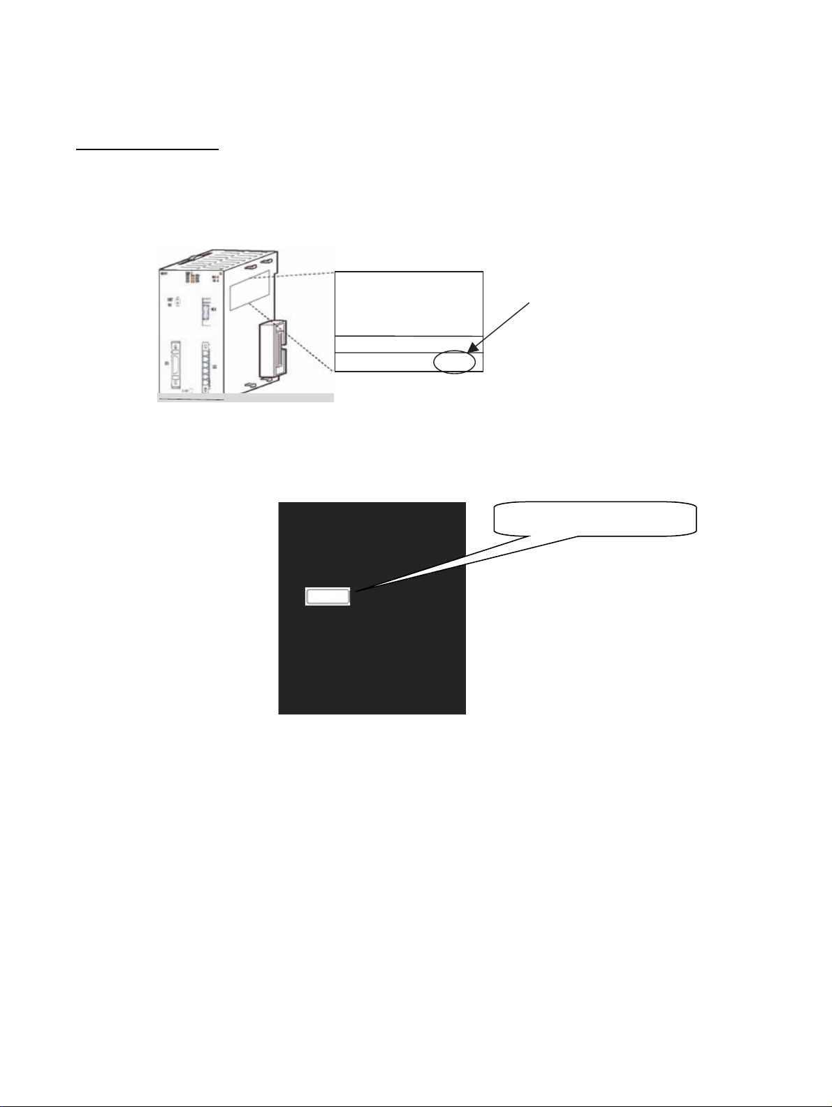
MC Unit
The unit version is given to the right of the lot number on the nameplate of the
applicable MC Units, as shown below.
Product nameplate
OMRON CJ1W- MCH71
MC UNIT
Lot No. 031001 0000 Ver.3.1
Unit version
Example for unit version 3.1
The unit version of the MC Units begins at version 2.0.
Identifying Unit Versions A unit version label is provided with the Advanced Motion Control Unit. This
label can be attached to the front of the Motion Control Unit to differentiate
between Motion Control Units of different Unit versions.
Attach the unit version label here.
Confirming Unit Versions
with Support Software
Ver. 3.1
The unit version 2.1 or later can be confirmed in Unit Manufacturing Informa-
tion of CX-Programmer version 4.0 or higher. Unit version 2.0 cannot be confirmed in Unit Manufacturing Information. Use the CX-Motion-MCH Support
Tool for Motion Control Units to confirm the unit version.
Example: Confirming Unit Version 2.1 or Later Using CX-Programmer
Version 4.0 or Higher
1. In the I/O Table Window, right-click the Motion Control Unit and select Unit
Manufacturing Information.
2. The following Unit Manufacturing Information Dialog Box will be displayed.
vii
Page 7
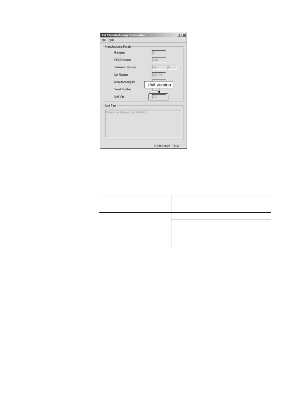
3. Unit version 3.1 will be displayed in the Unit Manufacturing Information Dialog Box.
Example: Confirming Unit Version 3.0 Using CX-Motion-MCH Support
Tool
Use the CX-Motion-MCH Support Tool for Motion Control Units to confirm the
unit version, as shown in the following table.
Method for confirming the internal
system software version
Corresponds to the unit version Internal system software version
The system software version in the Motion Control Unit can be checked in the Unit information
from the online menus.
CJ1W-MCH71 CS1W-MCH71
Unit Ver. 2.0:
Unit Ver. 2.1:
Unit Ver. 3.0:
Unit Ver. 3.1
1.05xxxx
1.06xxxx
1.07xxxx
1.09xxxx
1.05xxxx
---
1.08xxxx
1.09xxxx
viii
Page 8

Functions Supported by CJ1W-MCH71 Units Version 2.1 or Later
Unit version Unit Ver. 2.0 Unit Ver. 2.1 Unit Ver. 3.0 Unit Ver. 3.1
Internal system software version 1.05 1.06 1.07 1.09
MC Unit model CJ1W-MCH71
Functions Reading unit version function Not supported Supported Supported Supported
Expanded allocations in Custom
I/O Area
Data tracing Not supported Not supported
Debugging Not supported Not supported
Zones Not supported Not supported
Signed master axis MOVELINK command
Indirect writing of position data Not supported Not supported Supported Supported
Setting the number of parallel
branches for each task
Present position preset to establish
origin
Status of program start bit Not supported Not supported Supported Supported
Servo OFF for deceleration stop signal Not supported Not supported
Re-execution of WAIT command Not supported Not supported Supported Supported
Main power status Not supported Not supported Supported Supported
Servo Driver status Not supported Not supported Supported Supported
Increased precision of CAMBOX command
Improved restarting after restoration --- --- --- Supported
Expanded bank switching for interpolation acceleration/deceleration times
Internal overrides --- --- --- Supported
Connecting to SMARTSTEP Junior
Servo Drivers
Improved backup and restore functions
Program and CAM data read protection
Applicable Support Tool CX-Motion-MCH
Not supported Supported Supported Supported
*1
*1
*1
Supported
Supported
Supported
Supported
Supported
Supported
Not supported Not supported Supported Supported
Not supported Not supported
Not supported Not supported
Supported
Supported
Supported
*1
*1
*1
Supported
Supported
Supported
Not supported Not supported Supported Supported
--- --- --- Supported
--- --- ---
--- --- ---
--- --- ---
• Functions for unit version 3.0 indicated by “*1” can be used with CXMotion-MCH version 2.0 or higher.
Supported
Supported
Supported
• Functions for unit version 3.1 indicated by “*2” can be used with CXMotion-MCH version 2.1 or higher.
*1
*1
*1
*1
*1
*1
*2
*2
*2
CJ1W-MCH71 Unit Versions and Manufacturing Dates/Lot Numbers
Classification Type Model Manufacturing dates
Up to early
November
2004
CPU Bus Unit MC Unit CJ1W-MCH71 Unit version 2.0 Unit version 2.1
From middle of
November
2004
(Lot No.:
041117 and
later)
From early
Unit version 3.0
(Lot No.:
050615 and
later)
June
2005
From early
July
2007
Unit version 3.1
(Lot No.:
070615 and
later)
ix
Page 9

Functions Supported by CS1W-MCH71 Units Version 2.0 or Later
Unit version Pre-Ver. 2.0 Unit Ver. 2.0 Unit Ver. 3.0 Unit Ver. 3.1
Internal system software version 1.00 to 1.04 1.05 1.08 1.09
MC Unit model CS1W-MCH71
Functions Jogging --- Supported Supported Supported
Communications levels --- Supported Supported Supported
Communications cycle and unit cycle --- Supported Supported Supported
LATCH command processing time --- Supported Supported Supported
Latch status refresh time --- Suppor ted Supported Supported
Using interpolation commands during pass
operation
Acceleration/deceleration time during pass
operation
Deceleration time during pass operation --- Supported Supported Supported
Torque to position control switching --- Supported Supported Supported
Expanded allocations in Custom
I/O Area
Digital input values changed to improve
noise immunity
Faster unit cycle and communications cycle
times
Signed master axis MOVELINK command --- --- Supported Supported
Indirect writing of position data --- --- Supported Supported
Status of program start bit --- --- Supported Supported
Re-execution of WAIT command --- --- Supported Supported
Main power status --- --- Supported Supported
Servo Driver status --- --- Supported Supported
Increased precision of CAMBOX command --- --- Supported Supported
Data tracing --- ---
Debugging --- ---
Zones --- ---
Setting the number of parallel branches for
each task
Present position preset to establish origin --- ---
Servo OFF for deceleration stop signal --- ---
Improved restarting after restoration --- --- --- Supported
Expanded bank switching for interpolation
acceleration/deceleration times
Internal overrides --- --- --- Supported
Connecting to SMARTSTEP Junior Servo
Drivers
Improved backup and restore functions --- --- ---
Program and CAM data read protection --- --- ---
Applicable Support Tool CX-Motion-MCH
--- Supported Supported Supported
--- Supported Supported Supported
--- ---
Supported
*1
Supported
--- --- Supported Supported
--- --- Supported Supported
*1
*1
*1
*1
*1
*1
Supported
Supported
Supported
Supported
Supported
Supported
--- ---
Supported
Supported
Supported
Supported
Supported
Supported
--- --- --- Supported
--- --- ---
Supported
Supported
Supported
• Functions for unit version 3.0 indicated by “*1” can be used with CXMotion-MCH version 2.0 or higher.
• Functions for unit version 3.1 indicated by “*2” can be used with CXMotion-MCH version 2.1 or higher.
*1
*1
*1
*1
*1
*1
*1
*2
*2
*2
CS1W-MCH71 Unit Versions and Manufacturing Dates/Lot Numbers
Classification Type Model Manufacturing dates
From early
June
2004
CPU Bus Unit MC Unit CS1W-MCH71 Pre-Ver. 2.0 Unit version 2.0
From July 2004 From
March
2007
(Lot No.:
040715 and
later)
Unit version 3.0
(Lot No.:
070313 and
later)
From early
July
2007
Unit version 3.1
(Lot No.:
070615 and
later)
x
Page 10

Guide to Version Upgrades
Guide to CJ1W-MCH71 Version Upgrade
Function Upgrades from
Unit Version 3.0 to 3.1
Restarting after Restoration
Previous versions
(Unit Ver. 3.0 and earlier)
After data has been restored from the
CPU Unit's flash memory, the Unit must
be restarted by cycling the CPU Unit's
power supply.
After data has been restored from the
CPU Unit's flash memory, the Unit is
restarted using a bit between A50100 and
A50115 in the Auxiliary Area of the CPU
Unit. For details, refer to 7-1 Overview.
Current version
(Unit Ver. 3.1)
Expanded Bank Switching for Interpolation Acceleration/Deceleration
Times
Previous versions
(Unit Ver. 3.0 and earlier)
The acceleration time and deceleration time used for interpolation
operations cannot be set separately.
The acceleration time and deceleration time
used for interpolation operations can be set separately.
P00004, bit 13: Bank switching method selection
0: Select the same bank for acceleration and
deceleration (same as for version 3.0).
1: Select different banks for the acceleration
time and deceleration time.
Parameters P00M11 to P00M15 are used to set
acceleration times, and P00M16 to P00M20 are
used to set deceleration times. For details, refer
to 6-1 Basic Information.
Current version
(Unit Ver. 3.1)
Internal Overrides
Previous versions
(Unit Ver. 3.0 and earlier)
There is a function for changing
the axis feed rate from a ladder
program, but not from a motion
program.
The feed rate when the following commands are
executed can be changed from a motion program.
Commands for which an override can be specified from the motion program:
MOVE Rapid feed rate
DATUM Origin return feed rate
MOVEI Rapid feed rate, external position-
MOVET Rapid feed rate
The actual speed is as follows:
Actual speed = Axis feed rate x (Axis override +
Internal override)
For details, refer to 6-1 Basic Information.
Current version
(Unit Ver. 3.1)
ing rate
Connecting to SMART STEP Junior Servo Drivers
Previous versions
(Unit Ver. 3.0 and earlier)
Cannot be connected. Can be connected.
Current version
(Unit Ver. 3.1)
xi
Page 11

Backup and Restore Functions
Previous versions
(Unit Ver. 3.0 and earlier)
The origin compensation value
when an absolute encoder is used
is backed up using the CPU Unit's
easy backup function.
Origin compensation values can be backed up
even with CX-Motion-MCH version 2.1. For
details, refer to Section 11 Backup and Restore
in the CX-Motion-MCH Operation Manual (Cat.
No. W448).
Program and CAM Data Read Protection
Previous versions
(Unit Ver. 3.0 and earlier)
There is no program and CAM
data read protection.
The CX-Motion-MCH version 2.1 read protection
function (password setting), can be used to prevent third-parties from reading program and
CAM data. For details, refer to Section 12 Read
Protection in the CX-Motion-MCH Operation
Manual (Cat. No. W448).
Current version
(Unit Ver. 3.1)
Current version
(Unit Ver. 3.1)
Improved Functions from
Unit Ver. 2.1 Compared to
Unit Ver. 3.0
Data Tracing
Previous versions
(Unit Ver. 2.1 and earlier)
Data tracing is not supported. A data tracing function is provided that can
simultaneously collect a maximum of 32 data
items. This function does not affect previous
functionality. Previously reserved parameters
and variables are used to set and reference data
trace conditions and status.
For details, refer to 9-6 Data Tracing.
Current version
(Unit Ver. 3.0)
Debugging
Previous versions
(Unit Ver. 2.1 and earlier)
Breakpoints cannot be set. Debugging is supported using breakpoints that
are set using the Support Tool, and debugging is
supported for direct operation.
These functions do not affect previous functionality, but the following bit has been added to the
Unit status to indicate that debugging is being
executed from the Support Tool.
• CIO n+15, bit 09: Operating mode (Reserved in
previous unit versions.)
0: Normal mode
1: Support Tool mode (debugging)
Current version
(Unit Ver. 3.0)
xii
Page 12

Zones
Previous versions
(Unit Ver. 2.1 and earlier)
Zones are not supported. A maximum of 32 zone bits are available.
Zone bit: A bit that turns ON when any variable is
within the set range, and turns OFF when the
variable is outside of the range.
The previous function and the new function can
be switched using the following parameter.
• Parameter number: P00011 (Reserved in previ-
ous unit versions.)
• Setting: 0 to 32
0: Default. Same as previous function.
1 to 32: Use zone bits 1 to 32.
Parameters and variables that were previously
reserved are used to set zone upper and lower
limits.
For details, refer to 9-7 Zones.
Current version
(Unit Ver. 3.0)
Signed Master Axis MOVELINK Command
Previous versions
(Unit Ver. 2.1 and earlier)
The main axis input sign is ignored
and data is read as an absolute
travel distance.
The main axis input sign is evaluated and the
data is read as a signed travel distance.
This function enables the main axis to use the
feedback speed of an axis traveling at low
speed.
Current version (Unit Ver. 3.0)
Indirect Writing of Position Data
Previous versions
(Unit Ver. 2.1 and earlier)
Position data can be indirectly
read but cannot be indirectly written.
Current version (Unit Ver. 3.0)
Position data can be both read and written indirectly.
Example: Indirect Writing
@PL0000 = 1234;
“1234” will be assigned as the contents of the
address set in PL0000.
This function does not affect previous functionality.
xiii
Page 13

Setting the Number of Parallel Branches for Each Task
Previous versions
(Unit Ver. 2.1 and earlier)
The number of branches and the
number of commands that can be
executed are the same for each
task.
The number of branches and the number of
instructions that can be executed can be set
individually for each task, enabling fine adjustment of the Unit cycle.
The previous function and the new function can
be switched using the following parameter.
• Parameter number: P00004
• Bit 11 (Reserved in previous unit versions.)
Previously reserved parameters are used to set
the number of parallel branches individually for
each task.
Current version (Unit Ver. 3.0)
0: Default. Same as previous function.
1: Individually set the number of branches and
the number of commands that can executed
in each task.
Present Position Preset to Establish Origin
Previous versions
(Unit Ver. 2.1 and earlier)
The origin is not established when
the present position is set to the
preset value.
The origin is established when the present position is set to the preset value.
The previous function and the new function can
be switched using the following parameter.
• Parameter number: P00004
• Bit 12 (Reserved in previous unit versions.)
0: Default. Same as previous function.
1: Origin established for preset.
Current (Unit Ver. 3.0)
Program Start Bit Status
Previous versions
(Unit Ver. 2.1 and earlier)
An operation completed bit alone
cannot be used to detect the end
of programs with processing times
that are shorter than the Unit cycle
time.
The start bit ON/OFF status in the CPU Unit is
output to the task status bit.
Example for Axis 1:
• n+17 bit 06: start bit (Reserved in previous unit
versions.)
0: Start bit from CPU Unit OFF
1: Start bit from CPU Unit ON
The end of the relevant program can be
detected if this bit is ON and the operation completed bit is ON.
Servo OFF for Deceleration Stop Signal
Previous versions
(Unit Ver. 2.1 and earlier)
When the deceleration stop signal
for the Unit turns ON, all axes are
decelerated to a stop.
When the deceleration stop signal for the Unit
turns ON, the servo can be turned OFF for all
axes. The operation for servo OFF is set in the
Servo Driver parameters.
The previous function and the new function can
be switched using the following parameter.
• Parameter number: P00004
• Bit 10 (Reserved in previous unit versions.)
0: Default. Same as previous function.
1: Servo OFF
Current (Unit Ver. 3.0)
Current (Unit Ver. 3.0)
xiv
Page 14

Re-execution of WAIT Command
Previous versions
(Unit Ver. 2.1 and earlier)
If the program is stopped while
WAIT command execution is in
effect (i.e., when the deceleration
stop bit is ON) and then re-started
by setting the Start Mode to 1, the
program is started from the next
block after the WAIT command.
Main Power Status
Previous versions
(Unit Ver. 2.1 and earlier)
The main power status (ON/OFF)
is written to a system variable.
Servo Driver Status
Previous versions
(Unit Ver. 2.1 and earlier)
The Servo Driver warning and
alarm codes are stored in the error
log.
The Servo status (torque limit, limit
inputs, etc.) is output to system
variables (SW021C and SW021D
for axis 1.)
Current (Unit Ver. 3.0)
If the program is stopped while WAIT command
execution is in effect (i.e., when the deceleration
stop bit is ON) and then re-started by setting the
Start Mode to 1, the WAIT command is re-executed.
Current (Unit Ver. 3.0)
The main power status (ON/OFF) is written to
both a system variable and a status bit for each
axis.
Example for Axis 1:
• x+32 bit 12: Main power ON bit (reserved in
previous unit versions)
0: Main power OFF
1: Main power ON
The servo can be effectively locked from the
CPU Unit after confirming that this bit is ON.
Current (Unit Ver. 3.0)
In addition to the functionality supported in previous unit versions, Servo Driver warning codes,
alarm codes, and status (torque limit, limit
inputs, etc.) are also output to the following output variables that were reserved in previous unit
versions.
OW0210: Axis 1 Warning code/alarm code
OW0211: Axis 1 Status
(same as SW021C)
OW0212: Axis 1 Status
(same as SW021D)
to
OW026D: Axis 32 Warning code/alarm code
OW026E: Axis 32 Status
(Same as SW07EC)
OW026F: Axis 32 Status
(Same as SW07ED)
xv
Page 15

Compliance with RoHS Directive
Previous versions
(Unit Ver. 2.1 and earlier)
Lead was included in the cream solder
used to mount chip components, in the
flow solder used in assembly, and in
thread solder.
Solder type Main components
Cream solder Tin and lead
Flow solder Tin and lead
Thread solder Tin and lead
There is no mark indicating compliance
with the RoHS Directive.
Current version (Unit Ver. 3.0)
As shown below, lead is not used. There
is no change in specifications (including
outer appearance) resulting from this
change.
Solder type Main components
Cream solder (1) Tin, silver, indium, and
Flow solder (1) Tin and copper
Thread solder Tin, silver, and copper
Note: Either 1 or 2 shown above is used.
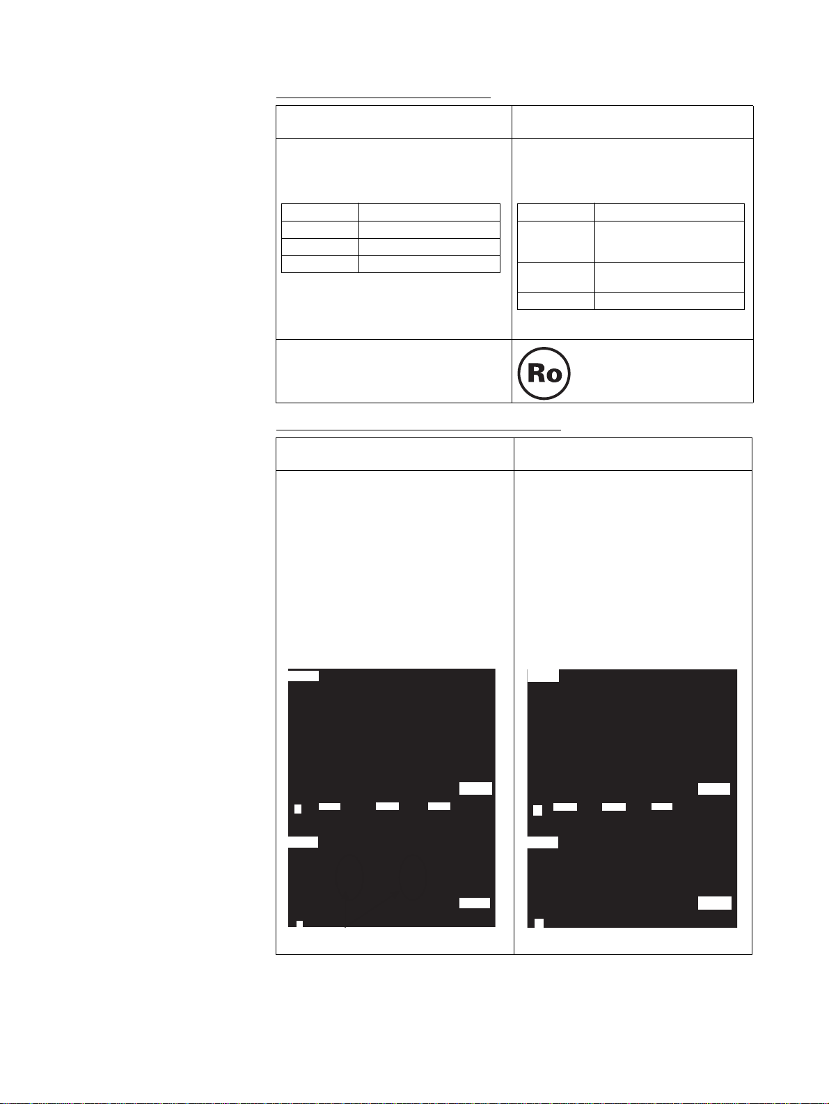
Increased Precision of CAMBOX Command
Previous versions
(Unit Ver. 2.1 and earlier)
If the slave axis CAM table is switched
during continuous master axis travel, part
of the slave axis travel is eliminated when
the CAM table is switched.
Example:
:
CAMBOX [J01]1 [J02]10000 K10000 Q8
B0;Cam 1
CAMBOX [J01]2 [J02]10000 K10000 Q8
B0;Cam 2
CAMBOX [J01]3 [J02]10000 K10000 Q8
B0;Cam 3
:
Slave axis
displacement
The slave axis will travel the set amount,
even if the slave axis CAM table is
switched during continuous master axis
travel.
Example:
:
CAMBOX [J01]1 [J02]10000 K10000 Q8
B0;Cam 1
CAMBOX [J01]2 [J02]10000 K10000 Q8
B0;Cam 2
CAMBOX [J01]3 [J02]10000 K10000 Q8
B0;Cam 3
:
Slave axis
displacement
bismuth
(2) Tin, silver, and copper
(2) Tin, silver, and copper
The RoHS compliance mark
is displayed.
Current (Unit Ver. 3.0)
xvi
Master axis phase
Cam 1 Cam 3Cam 2
0
Slave axis speed
Master axis
0
phase
This amount of travel is eliminated.
Cam 1 Cam 3Cam 2
0
Slave axis speed
0
Master axis phase
Master axis
phase
Page 16
Functions Added in
Version Upgrade
The following table provides a comparison between the functions provided in
the upgrade to unit version 2.1 or later of CJ1W-MCH71 SYSMAC CJ-series
Motion Control Units from the previous unit version 2.0.
Reading Unit Versions
Previous version (Unit Ver. 2.0) Present version (Unit Ver. 2.1)
The MC Unit's unit version code could not
be read by accessing the Unit Manufac-
turing Information in CX-Programmer
Ver.4.0.
The MC Unit's unit version code can be
read by accessing the Unit Manufacturing
Information in CX-Programmer Ver.4.0.
Expanded Allocations in Custom I/O Area
Previous version (Unit Ver. 2.0) Present version (Unit Ver. 2.1)
Only the I/O variable area determined in
advance could be allocated to the Custom I/O Area.
In addition to the I/O variable area, system variables, global general variables,
position data, and task variables for userspecified addresses can be allocated in
the Custom I/O Area.
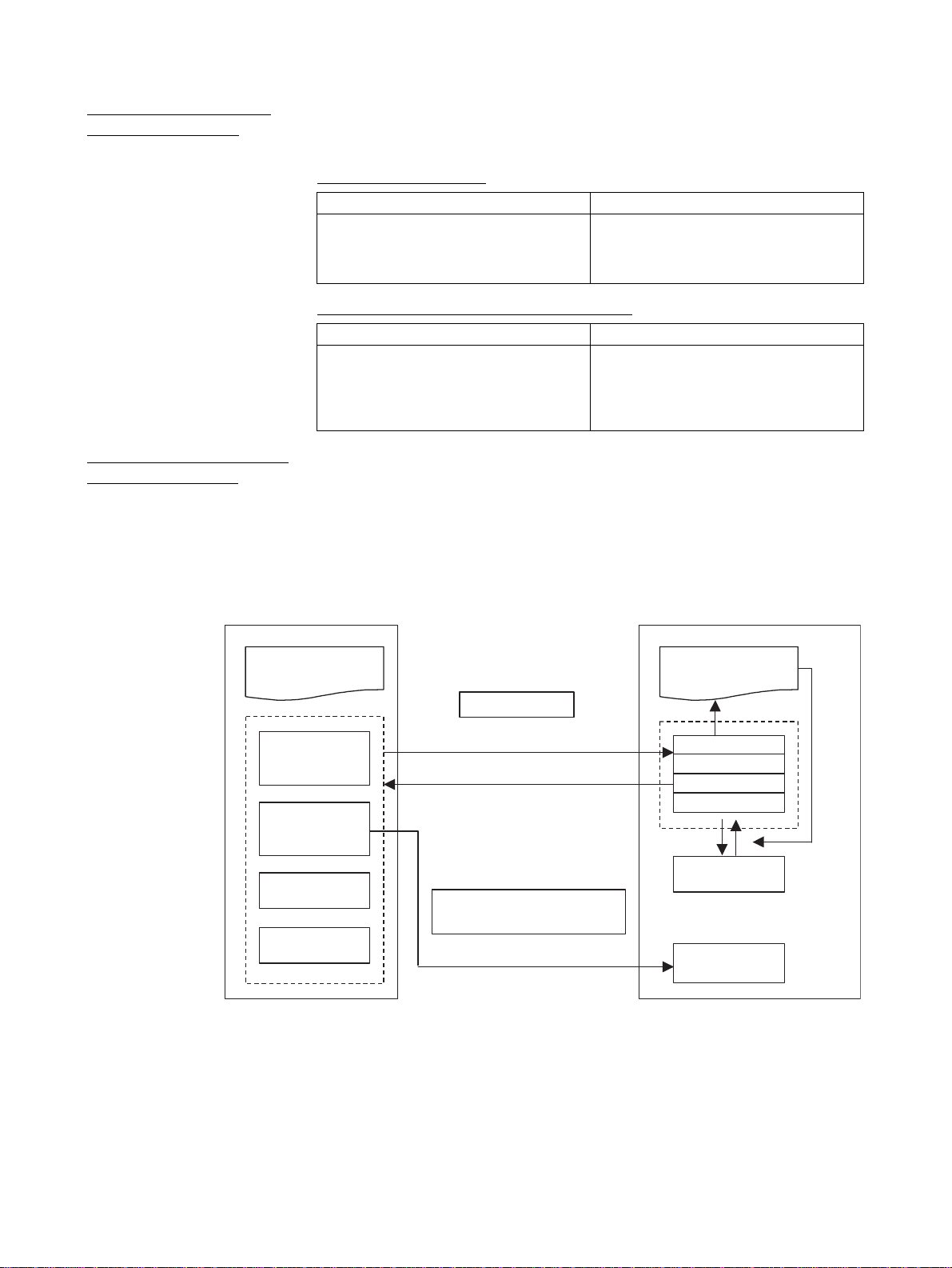
Expanded Custom I/O
Area Allocations
Ladder program
Overview
The CPU Unit can control MC Units with the following three different methods
of data I/O.
1. Data exchange with allocated bit area words.
2. Data exchange with allocated DM Area words.
3. Data exchange with allocated Custom Area words.
CPU Unit
Allocated Bit
Area words
Allocated DM
Area words
Custom Bit
Area words
Custom Data
Area words
I/O Refresh
Control
Status
When the power is
ON or restarting
Area range setting
MC Unit version 2.1 or higher
Motion program
Startup, Stop
Command analysis
General input
Status
General output
Variables
Set the Custom
Area range to use
Command
The function for exchanging data in the Custom I/O Area has been enhanced
with MC Units with unit version 2.1, as shown in the following table.
For details on previous specifications, refer to SECTION 7 PC Interface Area.
xvii
Page 17

No. Classification MC Unit Variable Area Area size
Previous version
(Unit Ver. 2.0)
1 General I/O A IW0B00 to IW0B9F or OW0B00 to
OW0B9F
2 General I/O B IW0BA0 to IW0C3F or OW0BA0 to
OW0C3F
3 General I/O C IW0C40 to IW0CDF or OW0C40 to
OW0CDF
4 General I/O D IW0CE0 to IW0D7F or OW0CE0
to OW0D7F
5 General I/O E IW0D80 to IW0E1F or OW0D80 to
OW0E1F
6 General I/O F IW0E20 to IW0EBF or OW0E20 to
OW0EBF
7 General I/O G IW0EC0 to IW0F5F or OW0EC0 to
OW0F5F
8 General I/O H IW0F60 to IW0FFF or OW0F60 to
OW0FFF
The variable area and addresses
can be allocated for the following
variables.
•System variables
• Global general variables
• Input variables
• Output variables
• Position data
•Task variable
Present version
(Unit Ver. 2.1)
0 to 160 words
0 to 160 words
0 to 160 words
0 to 160 words
0 to 160 words
0 to 160 words
0 to 160 words
0 to 160 words
xviii
Page 18

Guide to CS1W-MCH71 Version Upgrade
Function Upgrades from
Unit Version 3.0 to 3.1
Restarting after Restoration
Previous versions
(Unit Ver. 3.0 and earlier)
After data has been restored from the
CPU Unit's flash memory, the Unit must
be restarted by cycling the CPU Unit's
power supply.
After data has been restored from the
CPU Unit's flash memory, the Unit is
restarted using a bit between A50100 and
A50115 in the Auxiliary Area of the CPU
Unit. For details, refer to 7-1 Overview.
Current version
(Unit Ver. 3.1)
Expanded Bank Switching for Interpolation Acceleration/Deceleration
Times
Previous versions
(Unit Ver. 3.0 and earlier)
The acceleration time and deceleration time used for interpolation
operations cannot be set separately.
The acceleration time and deceleration time
used for interpolation operations can be set separately.
P00004, bit 13: Bank switching method selection
0: Select the same bank for acceleration and
deceleration (same as for version 3.0).
1: Select different banks for the acceleration
time and deceleration time.
Parameters P00M11 to P00M15 are used to set
acceleration times, and P00M16 to P00M20 are
used to set deceleration times. For details, refer
to 6-1 Basic Information.
Current version
(Unit Ver. 3.1)
Internal Overrides
Previous versions
(Unit Ver. 3.0 and earlier)
There is a function for changing
the axis feed rate from a ladder
program, but not from a motion
program.
The feed rate when the following commands are
executed can be changed from a motion program.
Commands for which an override can be specified from the motion program:
MOVE Rapid feed rate
DATUM Origin return feed rate
MOVEI Rapid feed rate, external position-
MOVET Rapid feed rate
The actual speed is as follows:
Actual speed = Axis feed rate x (Axis override +
Internal override)
For details, refer to 6-1 Basic Information.
Current version
(Unit Ver. 3.1)
ing rate
Connecting to SMART STEP Junior Servo Drivers
Previous versions
(Unit Ver. 3.0 and earlier)
Cannot be connected. Can be connected.
Current version
(Unit Ver. 3.1)
xix
Page 19

Backup and Restore Functions
Previous versions
(Unit Ver. 3.0 and earlier)
The origin compensation value
when an absolute encoder is used
is backed up using the CPU Unit's
easy backup function.
Origin compensation values can be backed up
even with CX-Motion-MCH version 2.1. For
details, refer to Section 11 Backup and Restore
in the CX-Motion-MCH Operation Manual (Cat.
No. W448).
Program and CAM Data Read Protection
Previous versions
(Unit Ver. 3.0 and earlier)
There is no program and CAM
data read protection.
The CX-Motion-MCH version 2.1 read protection
function (password setting), can be used to prevent third-parties from reading program and
CAM data. For details, refer to Section 12 Read
Protection in the CX-Motion-MCH Operation
Manual (Cat. No. W448).
Current version
(Unit Ver. 3.1)
Current version
(Unit Ver. 3.1)
Function Upgrades from
Unit Version 2.0 to 3.0
Expanded Allocations in Custom I/O Area
Previous version (Unit Ver. 2.0) Present version (Unit Ver. 3.0)
Only the I/O variable area determined in
advance could be allocated to the Custom I/O Area.
In addition to the I/O variables, system
variables, global general variables, position data, and task variables for userspecified addresses can be allocated to
the Custom I/O Area.
Digital Input Values Changed to Improve Noise Resistance
Previous version
(Unit Ver. 2.0)
Rated input voltage: 24 VDC ±10%
Rated input current: 4.06 to 4.48 mA
ON voltage: 9.5 V min.
OFF voltage: 4.5 V max.
Rated input voltage: 24 VDC ±10%
Rated input current: 4.02 to 4.52 mA
ON voltage: 14 V min.
OFF voltage: 6V max.
(Any sensors that were previous used can
still be used.)
Current version
(Unit Ver. 3.0)
Parameter Added for Faster Unit Cycle and Communications Cycle Time
Previous version
(Unit Ver. 2.0)
Unit cycle [us] = (115.0 × Number of
axes) + (165 × Number of motion tasks ×
Number of parallel branches) + (0.3 ×
Number of general allocation words) +
350.0
Communications cycle [us] = ((Number of
allocated Units + Number of retries) ×
133.3+26.2) × 1.1
Unit cycle [us] = (85 × Number of axes) +
(120 × Number of motion tasks × Number
of parallel branches) + (0.3 × number of
general allocation words) + 200
Communications cycle [us] = ((Number of
allocated Unit + Number of retries) ×
102.7 + 19.2) × 1.1
Use the following parameter to switch the
performance.
• Parameter number: P00004
• Bit: 09 (previously reserved)
0: Initial value. Performance is the
1: Selects faster performance.
Current version
(Unit Ver. 3.0)
same as before.
xx
Page 20

Signed Master Axis MOVELINK Command
Previous version
(Unit Ver. 2.0)
The main axis input sign is ignored
and data is read as an absolute
travel distance.
The main axis input sign is evaluated and the
data is read as a signed travel distance.
This function enables the main axis to use the
feedback speed of an axis traveling at low
speed.
Indirect Writing of Position Data
Previous version
(Unit Ver. 2.0)
Position data can be indirectly
read but cannot be indirectly written.
Position data can be both read and written indirectly.
Example: Indirect Writing
@PL0000 = 1234;
“1234” will be assigned as the contents of the
address set in PL0000.
This function does not affect previous functionality.
Program Start Bit Status
Previous version
(Unit Ver. 2.0)
An operation completed bit alone
cannot be used to detect the end
of programs with processing times
that are shorter than the Unit cycle
time.
The start bit ON/OFF status in the CPU Unit is
output to the task status bit.
Example for Axis 1:
• n+17 bit 06: start bit (Reserved in previous unit
versions.)
0: Start bit from CPU Unit OFF
1: Start bit from CPU Unit ON
The end of the relevant program can be
detected if this bit is ON and the operation completed bit is ON.
Current version
(Unit Ver. 3.0)
Current version
(Unit Ver. 3.0)
Current version
(Unit Ver. 3.0)
Re-execution of WAIT Command
Previous version
(Unit Ver. 2.0)
If the program is stopped while
WAIT command execution is in
effect (i.e., when the deceleration
stop bit is ON) and then re-started
by setting the Start Mode to 1, the
program is started from the next
block after the WAIT command.
Current version
(Unit Ver. 3.0)
If the program is stopped while WAIT command
execution is in effect (i.e., when the deceleration
stop bit is ON) and then re-started by setting the
Start Mode to 1, the WAIT command is re-executed.
xxi
Page 21

Main Power Status
Previous version
(Unit Ver. 2.0)
The main power status (ON/OFF)
is written to a system variable.
Servo Driver Status
Previous version
(Unit Ver. 2.0)
The Servo Driver warning and
alarm codes are stored in the error
log.
The Servo status (torque limit, limit
inputs, etc.) is output to system
variables (SW021C and SW021D
for axis 1.)
Current version
(Unit Ver. 3.0)
The main power status (ON/OFF) is written to
both a system variable and a status bit for each
axis.
Example for Axis 1:
• x+32 bit 12: Main power ON bit (reserved in
previous unit versions)
0: Main power OFF
1: Main power ON
The servo can be effectively locked from the
CPU Unit after confirming that this bit is ON.
Current version
(Unit Ver. 3.0)
In addition to the functionality supported in previous unit versions, Servo Driver warning codes,
alarm codes, and status (torque limit, limit
inputs, etc.) are also output to the following output variables that were reserved in previous unit
versions.
OW0210: Axis 1 Warning code/alarm code
OW0211: Axis 1 Status
(same as SW021C)
OW0212: Axis 1 Status
(same as SW021D)
to
OW026D: Axis 32 Warning code/alarm code
OW026E: Axis 32 Status
(Same as SW07EC)
OW026F: Axis 32 Status
(Same as SW07ED)
xxii
Page 22
Compliance with RoHS Directive
Previous version
(Unit Ver. 2.0)
Lead was included in the cream solder
used to mount chip components, in the
flow solder used in assembly, and in
thread solder.
Solder type Main components
Cream solder Tin and lead
Flow solder Tin and lead
Thread solder Tin and lead
As shown below, lead is not used. There
is no change in specifications (including
outer appearance) resulting from this
change.
Solder type Main components
Cream solder (1) Tin, silver, indium, and
Flow solder (1) Tin and copper
Thread solder Tin, silver, and copper
Note: Either 1 or 2 shown above is used.
There is no mark indicating compliance
with the RoHS Directive.
Increased Precision of CAMBOX Command
Previous version
(Unit Ver. 2.0)
If the slave axis CAM table is switched
during continuous master axis travel, part
of the slave axis travel is eliminated when
the CAM table is switched.
Example:
:
CAMBOX [J01]1 [J02]10000 K10000 Q8
B0;Cam 1
CAMBOX [J01]2 [J02]10000 K10000 Q8
B0;Cam 2
CAMBOX [J01]3 [J02]10000 K10000 Q8
B0;Cam 3
:
Slave axis
displacement
The slave axis will travel the set amount,
even if the slave axis CAM table is
switched during continuous master axis
travel.
Example:
:
CAMBOX [J01]1 [J02]10000 K10000 Q8
B0;Cam 1
CAMBOX [J01]2 [J02]10000 K10000 Q8
B0;Cam 2
CAMBOX [J01]3 [J02]10000 K10000 Q8
B0;Cam 3
:
Slave axis
displacement
Current version
(Unit Ver. 3.0)
bismuth
(2) Tin, silver, and copper
(2) Tin, silver, and copper
The RoHS compliance mark
is displayed.
Current version
(Unit Ver. 3.0)
Master axis phase
Cam 1 Cam 3Cam 2
0
Slave axis speed
Master axis
0
phase
This amount of travel is eliminated.
Cam 1 Cam 3Cam 2
0
Slave axis speed
0
Master axis phase
Master axis
phase
xxiii
Page 23

The following functions can be used with CX-Motion-MCH version 2.0 or higher (available from August
2006).
Data Tracing
Previous version
(Unit Ver. 2.0)
Data tracing is not supported. A data tracing function is provided that can
simultaneously collect a maximum of 32 data
items. This function does not affect previous
functionality. Previously reserved parameters
and variables are used to set and reference data
trace conditions and status.
Current version
(Unit Ver. 3.0)
Debugging
Previous version
(Unit Ver. 2.0)
Breakpoints cannot be set. Debugging is supported using breakpoints that
are set using the Support Tool, and debugging is
supported for direct operation.
These functions do not affect previous functionality, but the following bit has been added to the
Unit status to indicate that debugging is being
executed from the Support Tool.
• CIO n+15, bit 09: Operating mode (Reserved in
previous unit versions.)
0: Normal mode
1: Support Tool mode (debugging)
Current version
(Unit Ver. 3.0)
Zones
Previous version
(Unit Ver. 2.0)
Zones are not supported. A maximum of 32 zone bits are available.
Zone bit: A bit that turns ON when any variable is
within the set range, and turns OFF when the
variable is outside of the range.
The previous function and the new function can
be switched using the following parameter.
• Parameter number: P00011 (Reserved in previ-
ous unit versions.)
• Setting: 0 to 32
0: Default. Same as previous function.
1 to 32: Use zone bits 1 to 32.
Parameters and variables that were previously
reserved are used to set zone upper and lower
limits.
Current version
(Unit Ver. 3.0)
xxiv
Page 24

Setting the Number of Parallel Branches for Each Task
Previous version
(Unit Ver. 2.0)
The number of branches and the
number of commands that can be
executed are the same for each
task.
The number of branches and the number of
instructions that can be executed can be set
individually for each task, enabling fine adjustment of the Unit cycle.
The previous function and the new function can
be switched using the following parameter.
• Parameter number: P00004
• Bit 11 (Reserved in previous unit versions.)
0: Default. Same as previous function.
1: Individually set the number of branches and
the number of commands that can executed
in each task.
Previously reserved parameters are used to set
the number of parallel branches individually for
each task.
Current version
(Unit Ver. 3.0)
Present Position Preset to Establish Origin
Previous version
(Unit Ver. 2.0)
The origin is not established when
the present position is set to the
preset value.
The origin is established when the present position is set to the preset value.
The previous function and the new function can
be switched using the following parameter.
• Parameter number: P00004
• Bit 12 (Reserved in previous unit versions.)
0: Default. Same as previous function.
1: Origin established for preset.
Current version
(Unit Ver. 3.0)
Servo OFF for Deceleration Stop Signal
Previous version
(Unit Ver. 2.0)
When the deceleration stop signal
for the Unit turns ON, all axes are
decelerated to a stop.
When the deceleration stop signal for the Unit
turns ON, the servo can be turned OFF for all
axes. The operation for servo OFF is set in the
Servo Driver parameters.
The previous function and the new function can
be switched using the following parameter.
• Parameter number: P00004
• Bit 10 (Reserved in previous unit versions.)
0: Default. Same as previous function.
1: Servo OFF
Current version
(Unit Ver. 3.0)
xxv
Page 25

Function Improvements
for Unit Version 2.0
Jogging
Previous versions Current version (Unit Ver. 2.0)
The JOG feed direction is set or reversed
as follows:
• Use the JOG/STEP Direction Bit to
specify the feed direction.
• Turn ON the JOG Bit.
• To reverse the feed direction, turn OFF
the JOG Bit.
• After the axis is stopped, reverse the
JOG/STEP Direction Bit.
• Turn ON the JOG Bit. The feed direction
will be reversed.
Communications Levels
Previous versions Current version (Unit Ver. 2.0 or later)
The MC Unit supported communications
on up to three levels.
As shown below, a setting for reverse
operation has been added.
• Use the JOG/STEP Direction Bit to specify the feed direction.
• Turn ON the JOG Bit.
• The feed direction is reversed by reversing the JOG/STEP Direction Bit even
while the JOG Bit still ON.
Use the following parameter to switch the
previous function and the new one.
• Parameter number: P00004
• Bit: 05 (previously reserved)
0: Initial value. Same as previous func-
tion.
1: Selects new function.
The MC Unit supports communications on
up to eight levels, according to the eight
levels supported by the CPU Unit. The
CPU Unit supports eight levels with unit
version 2.0 or later.
Communications Cycle and Unit Cycle
Previous versions Current version (Unit Ver. 2.0 or later)
The MC Unit communications cycle and
unit cycle times are as follows:
Communications cycle: 1 ms, 2 ms, 4 ms
Unit cycle: 1 ms, 2 ms, 4 ms, 8 ms
• Supporting a communications cycle of
• Use the following parameter to switch the
LATCH Command Processing Time
Previous versions Current version (Unit Ver. 2.0 or later)
The time from when the LATCH command is executed until the external latch
signal is detected is as follows:
• When latch signals are received at any
position: 105 to 232 ms
• When only latch signals in a specified
position range are received: 105 to
232 ms
As shown below, performance is improved
in cases where latch signals are received
at any position.
• When latch signals are received at any
• When only latch signals in a specified
3 ms enable more precise performance.
Communications cycle: 1 ms, 2 ms,
3ms, 4 ms
Unit cycle: 1 ms, 2 ms, 3 ms, 4 ms, 6 ms,
8 ms
previous function and the new one.
Parameter number: P00004
Bit: 03 (previously reserved)
0: Initial value. Same as previous func-
tion.
1: Enables use of 3 ms.
position: 3 to 24 ms
position range are received: 105 to
232 ms
xxvi
Page 26

Latch Status Refresh Time
Previous versions Current version (Unit Ver. 2.0 or later)
After a LATCH command is executed, the
time from when the latch signal is input
until it is reflected in the system variable
(the variable showing latch completion) is
14.5 to 85.5 ms.
The performance has been improved as
follows:7.5 to 37.5 ms
Using Interpolation Commands during Pass Operation
Previous versions Current version (Unit Ver. 2.0 or later)
To execute pass operation from a
stopped axis, two interpolation commands are required for the initial operation.
Example:
:
PASSMODE;
MOVEL [J01]100 F10000;
MOVEL [J02]400 F10000;
WHILE #MW0000==0;
INC MOVEL [J02]100 F1000;
WEND;
:
To execute pass operation from a stopped
axis, only one interpolation command is
required.
Example:
:
PASSMODE;
WHILE #MW0000==0;
INC MOVEL [J02]100 F1000;
WEND;
:
Acceleration/Deceleration Times during Pass Operation
Previous versions Current version (Unit Ver. 2.0 or later)
Changing the acceleration/
deceleration times during pass
operation was complex at any
time. It was necessary to use
the PARALLEL command to
execute parallel processing.
• The acceleration/deceleration times can be
changed during pass operation.
• As shown below, switching is made easy by using
a newly added parameter.
MOVEL [J01]1000 F1000
#W0A00 = 2;
MOVEL [J01]5000 F1000
• The following ten newly added parameters use part
of the task parameter area that was previously
reserved. Setting range: 0 to 60,000 (ms)
Number Name
P00M11 Interpolation feed acceleration/
deceleration time, Bank 1
::
P00M20 Interpolation feed acceleration/
deceleration time, Bank 10
← The time set in bank 2
is used for passing to
the next position.
xxvii
Page 27
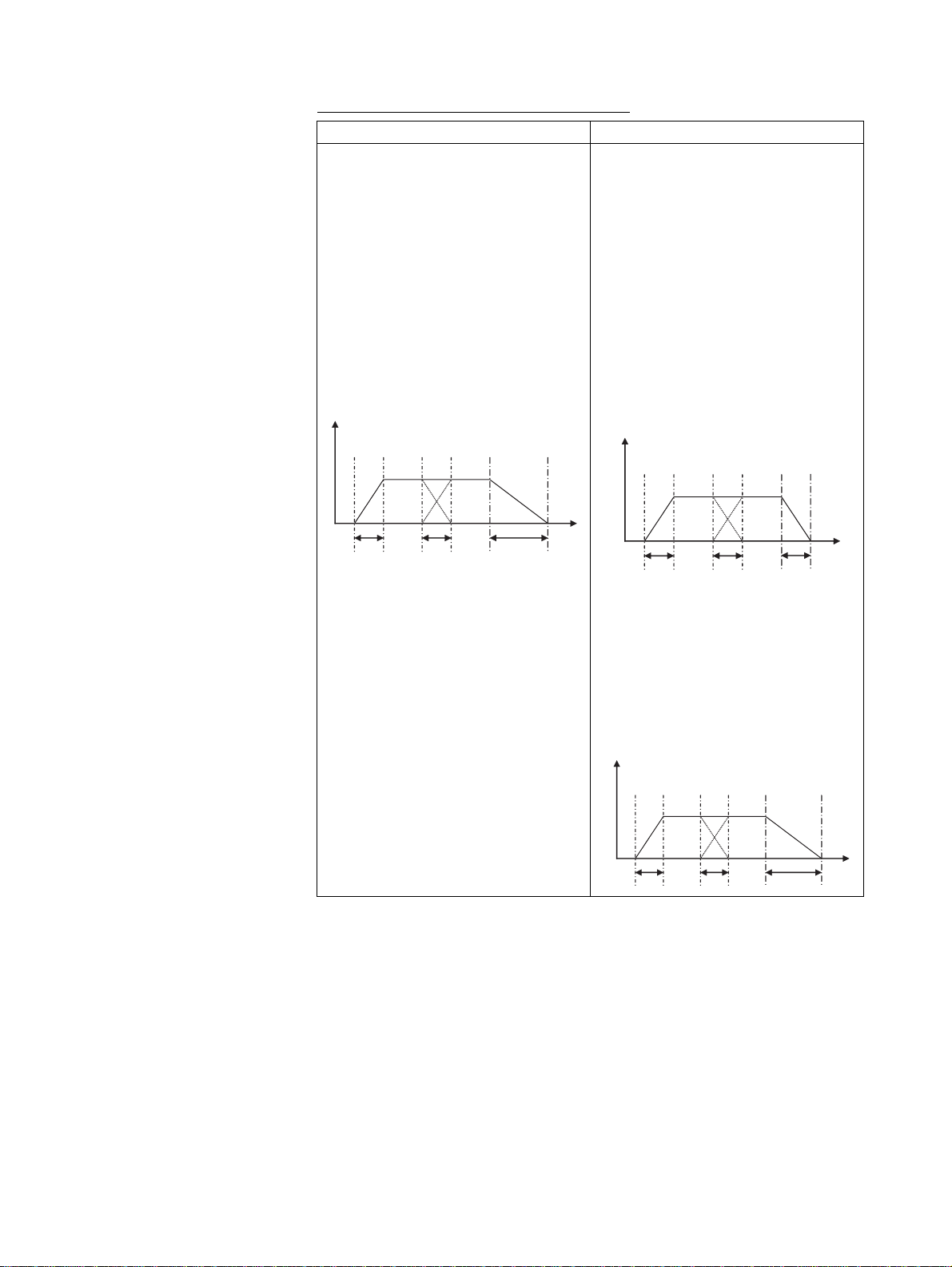
Deceleration Time during Pass Operation
e
Previous versions Current version (Unit Ver. 2.0 or later)
The interpolation feed deceleration time
is used to decelerate to a stop during
pass operation.
Example: Pass Mode Selection, P00M06
= 0
Interpolation feed acceleration time Ta =
P0MM02
Interpolation feed deceleration time Td =
P00M03
Program
PASSMODE;
INC MOVEL [J01]1000 F100000;
INC MOVEL [J01]1000 F100000;
END;
Speed
Ta Ta Td
• The interpolation time used during pass
operation (the interpolation feed acceleration time or the interpolation feed
deceleration time) is used to decelerate
to a stop during pass operation.
Example: Pass Mode Selection,
P00M06 = 0
Interpolation feed acceleration time Ta =
P0MM02
Interpolation feed deceleration time Td =
P00M03
Program
Speed
Tim
• To stop at the interpolation feed deceleration speed as previously, add STOPMODE before the final interpolation
command as shown below.
PASSMODE;
INC MOVEL [J01]1000 F100000;
INC MOVEL [J01]1000 F100000;
END;
Ta
Ta
Ta
PASSMODE;
INC MOVEL [J01]1000 F100000;
STOPMODE;
INC MOVEL [J01]1000 F100000;
END;
Time
Speed
Ta Ta Td
Time
xxviii
Page 28

Torque to Position Control Switching
Previous versions Current version (Unit Ver. 2.0 or later)
Switching from torque control to position
control using the TORQUR command is
executed when the axis feedback speed
reaches 0.
Speed to Position Control Switching
Previous versions Current version (Unit Ver. 2.0 or later)
Switching from speed control to position
control using the SPEEDR command is
executed when the axis feedback speed
reaches 0.
• Switching from torque control to position
control using the TORQUR command is
executed by switching to position control
when the axis feedback speed reaches
the speed specified in a parameter
(specified by a percentage of the rated
speed).
• The following newly added parameter
uses part of the axis parameter area
that was previously reserved.
Number Name
P3AA09 Position control switching
speed
Setting range: 0 to 32,767
(0.01%)
• Switching from speed control to position
control using the SPEEDR command is
executed when the axis feedback speed
reaches the speed specified in a parameter (specified by a percentage of the
rated speed).
• The following newly added parameter
uses part of the axis parameter area
that was previously reserved.
Number Name
P3AA09 Position control switching
speed
Setting range: 0 to 32,767
(0.01%)
xxix
Page 29

xxx
Page 30

TABLE OF CONTENTS
PRECAUTIONS . . . . . . . . . . . . . . . . . . . . . . . . . . . . . . . . . . . xli
1 Intended Audience . . . . . . . . . . . . . . . . . . . . . . . . . . . . . . . . . . . . . . . . . . . . . . . . . . . . . . . . . xlii
2 General Precautions . . . . . . . . . . . . . . . . . . . . . . . . . . . . . . . . . . . . . . . . . . . . . . . . . . . . . . . . xlii
3 Safety Precautions . . . . . . . . . . . . . . . . . . . . . . . . . . . . . . . . . . . . . . . . . . . . . . . . . . . . . . . . . xliii
4 Application Precautions. . . . . . . . . . . . . . . . . . . . . . . . . . . . . . . . . . . . . . . . . . . . . . . . . . . . .xliv
5 Operating Environment Precautions . . . . . . . . . . . . . . . . . . . . . . . . . . . . . . . . . . . . . . . . . . . xlv
6 Conformance to EC Directives . . . . . . . . . . . . . . . . . . . . . . . . . . . . . . . . . . . . . . . . . . . . . . . xlvi
SECTION 1
Features and System Configuration . . . . . . . . . . . . . . . . . . . 1
1-1 Features . . . . . . . . . . . . . . . . . . . . . . . . . . . . . . . . . . . . . . . . . . . . . . . . . . . . . . . . . . . . . . . . . 2
1-2 System Configuration . . . . . . . . . . . . . . . . . . . . . . . . . . . . . . . . . . . . . . . . . . . . . . . . . . . . . . 4
1-3 Basic Operations . . . . . . . . . . . . . . . . . . . . . . . . . . . . . . . . . . . . . . . . . . . . . . . . . . . . . . . . . . 6
1-4 Control System Configuration and Principles . . . . . . . . . . . . . . . . . . . . . . . . . . . . . . . . . . . . 11
1-5 Performance Specifications . . . . . . . . . . . . . . . . . . . . . . . . . . . . . . . . . . . . . . . . . . . . . . . . . .12
1-6 Command List . . . . . . . . . . . . . . . . . . . . . . . . . . . . . . . . . . . . . . . . . . . . . . . . . . . . . . . . . . . . 18
1-7 Performance. . . . . . . . . . . . . . . . . . . . . . . . . . . . . . . . . . . . . . . . . . . . . . . . . . . . . . . . . . . . . . 21
SECTION 2
Basic Procedures . . . . . . . . . . . . . . . . . . . . . . . . . . . . . . . . . . . 25
2-1 Basic Operation Flow . . . . . . . . . . . . . . . . . . . . . . . . . . . . . . . . . . . . . . . . . . . . . . . . . . . . . . 26
2-2 Overview of CX-Motion-MCH . . . . . . . . . . . . . . . . . . . . . . . . . . . . . . . . . . . . . . . . . . . . . . . 28
SECTION 3
Installation and Wiring . . . . . . . . . . . . . . . . . . . . . . . . . . . . . 31
3-1 Nomenclature and Functions . . . . . . . . . . . . . . . . . . . . . . . . . . . . . . . . . . . . . . . . . . . . . . . . . 32
3-2 Installation . . . . . . . . . . . . . . . . . . . . . . . . . . . . . . . . . . . . . . . . . . . . . . . . . . . . . . . . . . . . . . . 34
3-3 External I/O Circuitry . . . . . . . . . . . . . . . . . . . . . . . . . . . . . . . . . . . . . . . . . . . . . . . . . . . . . . 38
3-4 Wiring . . . . . . . . . . . . . . . . . . . . . . . . . . . . . . . . . . . . . . . . . . . . . . . . . . . . . . . . . . . . . . . . . . 42
3-5 Connecting MECHATROLINK Devices. . . . . . . . . . . . . . . . . . . . . . . . . . . . . . . . . . . . . . . . 43
SECTION 4
MC Unit Internal Data Configuration and Setting . . . . . . . 55
4-1 Data Configuration . . . . . . . . . . . . . . . . . . . . . . . . . . . . . . . . . . . . . . . . . . . . . . . . . . . . . . . . 56
4-2 System Parameters. . . . . . . . . . . . . . . . . . . . . . . . . . . . . . . . . . . . . . . . . . . . . . . . . . . . . . . . . 58
4-3 Variables . . . . . . . . . . . . . . . . . . . . . . . . . . . . . . . . . . . . . . . . . . . . . . . . . . . . . . . . . . . . . . . . 105
4-4 Position Data . . . . . . . . . . . . . . . . . . . . . . . . . . . . . . . . . . . . . . . . . . . . . . . . . . . . . . . . . . . . . 107
4-5 System Variables . . . . . . . . . . . . . . . . . . . . . . . . . . . . . . . . . . . . . . . . . . . . . . . . . . . . . . . . . . 111
4-6 I/O Variables . . . . . . . . . . . . . . . . . . . . . . . . . . . . . . . . . . . . . . . . . . . . . . . . . . . . . . . . . . . . . 160
4-7 Present Position Preset. . . . . . . . . . . . . . . . . . . . . . . . . . . . . . . . . . . . . . . . . . . . . . . . . . . . . . 190
4-8 Servo Parameter. . . . . . . . . . . . . . . . . . . . . . . . . . . . . . . . . . . . . . . . . . . . . . . . . . . . . . . . . . . 191
4-9 CAM Data . . . . . . . . . . . . . . . . . . . . . . . . . . . . . . . . . . . . . . . . . . . . . . . . . . . . . . . . . . . . . . . 210
xxxi
Page 31

TABLE OF CONTENTS
SECTION 5
Data Transfer and Storage. . . . . . . . . . . . . . . . . . . . . . . . . . . 211
5-1 Data Transfer and Storage . . . . . . . . . . . . . . . . . . . . . . . . . . . . . . . . . . . . . . . . . . . . . . . . . . .212
5-2 IOWR Instruction to Transfer Data . . . . . . . . . . . . . . . . . . . . . . . . . . . . . . . . . . . . . . . . . . . . 221
5-3 IORD Instruction to Transfer Data . . . . . . . . . . . . . . . . . . . . . . . . . . . . . . . . . . . . . . . . . . . . 228
5-4 Saving Data . . . . . . . . . . . . . . . . . . . . . . . . . . . . . . . . . . . . . . . . . . . . . . . . . . . . . . . . . . . . . . 234
SECTION 6
Programming . . . . . . . . . . . . . . . . . . . . . . . . . . . . . . . . . . . . . 239
6-1 Basic Information . . . . . . . . . . . . . . . . . . . . . . . . . . . . . . . . . . . . . . . . . . . . . . . . . . . . . . . . . 240
6-2 Command Overview . . . . . . . . . . . . . . . . . . . . . . . . . . . . . . . . . . . . . . . . . . . . . . . . . . . . . . .286
6-3 Command Details . . . . . . . . . . . . . . . . . . . . . . . . . . . . . . . . . . . . . . . . . . . . . . . . . . . . . . . . . 298
SECTION 7
PC Interface Area . . . . . . . . . . . . . . . . . . . . . . . . . . . . . . . . . . 373
7-1 Overview . . . . . . . . . . . . . . . . . . . . . . . . . . . . . . . . . . . . . . . . . . . . . . . . . . . . . . . . . . . . . . . . 374
7-2 Operating Mode. . . . . . . . . . . . . . . . . . . . . . . . . . . . . . . . . . . . . . . . . . . . . . . . . . . . . . . . . . . 382
7-3 Allocations for the CPU Unit . . . . . . . . . . . . . . . . . . . . . . . . . . . . . . . . . . . . . . . . . . . . . . . . 396
7-4 Interface Specifics . . . . . . . . . . . . . . . . . . . . . . . . . . . . . . . . . . . . . . . . . . . . . . . . . . . . . . . . . 420
SECTION 8
Establishing the Origin. . . . . . . . . . . . . . . . . . . . . . . . . . . . . . 531
8-1 Overview . . . . . . . . . . . . . . . . . . . . . . . . . . . . . . . . . . . . . . . . . . . . . . . . . . . . . . . . . . . . . . . . 532
8-2 Input Signals Required for Origin search . . . . . . . . . . . . . . . . . . . . . . . . . . . . . . . . . . . . . . . 534
8-3 Origin Search Methods and Parameters . . . . . . . . . . . . . . . . . . . . . . . . . . . . . . . . . . . . . . . . 534
8-4 Origin Search Operations . . . . . . . . . . . . . . . . . . . . . . . . . . . . . . . . . . . . . . . . . . . . . . . . . . .536
8-5 Absolute (ABS) Encoders . . . . . . . . . . . . . . . . . . . . . . . . . . . . . . . . . . . . . . . . . . . . . . . . . . .539
8-6 ABS Encoder Origin Setting . . . . . . . . . . . . . . . . . . . . . . . . . . . . . . . . . . . . . . . . . . . . . . . . . 540
SECTION 9
Other Operations . . . . . . . . . . . . . . . . . . . . . . . . . . . . . . . . . . 545
9-1 Teaching. . . . . . . . . . . . . . . . . . . . . . . . . . . . . . . . . . . . . . . . . . . . . . . . . . . . . . . . . . . . . . . . . 546
9-2 Debugging the Program. . . . . . . . . . . . . . . . . . . . . . . . . . . . . . . . . . . . . . . . . . . . . . . . . . . . .553
9-3 Coordinate System. . . . . . . . . . . . . . . . . . . . . . . . . . . . . . . . . . . . . . . . . . . . . . . . . . . . . . . . . 558
9-4 Backup and Restore Function . . . . . . . . . . . . . . . . . . . . . . . . . . . . . . . . . . . . . . . . . . . . . . . . 566
9-5 Servo Driver Status Output . . . . . . . . . . . . . . . . . . . . . . . . . . . . . . . . . . . . . . . . . . . . . . . . . .569
9-6 Data Tracing . . . . . . . . . . . . . . . . . . . . . . . . . . . . . . . . . . . . . . . . . . . . . . . . . . . . . . . . . . . . . 570
9-7 Zones . . . . . . . . . . . . . . . . . . . . . . . . . . . . . . . . . . . . . . . . . . . . . . . . . . . . . . . . . . . . . . . . . . . 571
xxxii
Page 32

TABLE OF CONTENTS
SECTION 10
Program Example . . . . . . . . . . . . . . . . . . . . . . . . . . . . . . . . . . 573
10-1 Program Example . . . . . . . . . . . . . . . . . . . . . . . . . . . . . . . . . . . . . . . . . . . . . . . . . . . . . . . . . 574
10-2 Slave Modules . . . . . . . . . . . . . . . . . . . . . . . . . . . . . . . . . . . . . . . . . . . . . . . . . . . . . . . . . . . . 607
10-3 Others. . . . . . . . . . . . . . . . . . . . . . . . . . . . . . . . . . . . . . . . . . . . . . . . . . . . . . . . . . . . . . . . . . . 619
SECTION 11
Troubleshooting . . . . . . . . . . . . . . . . . . . . . . . . . . . . . . . . . . . 627
11-1 Troubleshooting. . . . . . . . . . . . . . . . . . . . . . . . . . . . . . . . . . . . . . . . . . . . . . . . . . . . . . . . . . . 628
11-2 Countermeasures . . . . . . . . . . . . . . . . . . . . . . . . . . . . . . . . . . . . . . . . . . . . . . . . . . . . . . . . . . 634
11-3 Error Indicators . . . . . . . . . . . . . . . . . . . . . . . . . . . . . . . . . . . . . . . . . . . . . . . . . . . . . . . . . . . 638
11-4 Unit-related Alarm Codes . . . . . . . . . . . . . . . . . . . . . . . . . . . . . . . . . . . . . . . . . . . . . . . . . . . 639
11-5 Motion Task-related Alarm Codes. . . . . . . . . . . . . . . . . . . . . . . . . . . . . . . . . . . . . . . . . . . . . 642
11-6 Axis-related Alarm Codes . . . . . . . . . . . . . . . . . . . . . . . . . . . . . . . . . . . . . . . . . . . . . . . . . . .648
11-7 MLK Device Alarm Codes . . . . . . . . . . . . . . . . . . . . . . . . . . . . . . . . . . . . . . . . . . . . . . . . . . 653
11-8 Servo Driver Warnings. . . . . . . . . . . . . . . . . . . . . . . . . . . . . . . . . . . . . . . . . . . . . . . . . . . . . . 655
11-9 Error Log . . . . . . . . . . . . . . . . . . . . . . . . . . . . . . . . . . . . . . . . . . . . . . . . . . . . . . . . . . . . . . . . 656
SECTION 12
Maintenance and Inspection . . . . . . . . . . . . . . . . . . . . . . . . . 659
12-1 Routine Inspection . . . . . . . . . . . . . . . . . . . . . . . . . . . . . . . . . . . . . . . . . . . . . . . . . . . . . . . . . 660
Appendices
A Performance . . . . . . . . . . . . . . . . . . . . . . . . . . . . . . . . . . . . . . . . . . . . . . . . . . . . . . . . . . . . . 663
B Main Parameter Settings when Connecting W-series Servo Driver with
Built-in MECHATROLINK-II Communications . . . . . . . . . . . . . . . . . . . . . . . . . . . . . . . . . 667
Revision History . . . . . . . . . . . . . . . . . . . . . . . . . . . . . . . . . . . 671
xxxiii
Page 33

xxxiv
Page 34

About this Manual:
This manual describes the installation and operation of the CJ1W-MCH71 and CS1W-MCH71 Motion
Control Units (MC Units) and includes the sections described below.
Please read this manual carefully and be sure you understand the information provided before
attempting to install or operate the MC Unit. Be sure to read the precautions provided in the following
section.
Precautions provides general precautions for using the Motion Control Unit, Programmable Controller,
and related devices.
Section 1 introduces the features and system configuration of the CJ1W-MCH71 and CS1W-MCH71
Motion Control Units. It also describes product operating principles and provides product specifications.
Section 2 provides an overview of the basic procedures required to use the CJ1W-MCH71 and
CS1W-MCH71 Motion Control Units.
Section 3 describes the names of Unit parts and how to install and wire the CJ1W-MCH71 and CS1WMCH71 Motion Control Units.
Section 4 describes the data configuration uses to set up, operate, and monitor the CJ1W-MCH71 and
CS1W-MCH71 Motion Control Units and related devices.
Section 5 describes how to transfer data between the CPU Unit and the CJ1W-MCH71 and CS1WMCH71 Motion Control Units and how data is stored.
Section 6 describes how to program CJ1W-MCH71 and CS1W-MCH71 Motion Control Units operation, including the program configuration and the specific commands used in programming.
Section 7 describes the interface area in the CPU Unit used to control and monitor the CJ1W-MCH71
and CS1W-MCH71 Motion Control Units.
Section 8 describes how to establish the origin in the positioning system.
Section 9 describes special operations for the CJ1W-MCH71 and CS1W-MCH71 Motion Control
Units, including teaching, program debugging, coordinate systems, and backup functions.
Section 10 provides a programming example to demonstrate how the CJ1W-MCH71 and CS1WMCH71 Motion Control Units can be used.
Section 11 describes how to troubleshoot problems that may occur when using the CJ1W-MCH71
and CS1W-MCH71 Motion Control Units.
Section 12 describes the maintenance and inspection procedures required to keep the CJ1W-MCH71
and CS1W-MCH71 Motion Control Units in optimum condition.
The Appendix describes the performance of the Motion Control Units.
Registered Trademark
• MECHATROLINK is a registered trademark of the MECHATROLINK Members Association.
xxxv
Page 35

xxxvi
Page 36

Read and Understand this Manual
Please read and understand this manual before using the product. Please consult your OMRON
representative if you have any questions or comments.
Warranty and Limitations of Liability
WARRANTY
OMRON's exclusive warranty is that the products are free from defects in materials and workmanship for a
period of one year (or other period if specified) from date of sale by OMRON.
OMRON MAKES NO WARRANTY OR REPRESENTATION, EXPRESS OR IMPLIED, REGARDING NONINFRINGEMENT, MERCHANTABILITY, OR FITNESS FOR PARTICULAR PURPOSE OF THE
PRODUCTS. ANY BUYER OR USER ACKNOWLEDGES THAT THE BUYER OR USER ALONE HAS
DETERMINED THAT THE PRODUCTS WILL SUITABLY MEET THE REQUIREMENTS OF THEIR
INTENDED USE. OMRON DISCLAIMS ALL OTHER WARRANTIES, EXPRESS OR IMPLIED.
LIMITATIONS OF LIABILITY
OMRON SHALL NOT BE RESPONSIBLE FOR SPECIAL, INDIRECT, OR CONSEQUENTIAL DAMAGES,
LOSS OF PROFITS OR COMMERCIAL LOSS IN ANY WAY CONNECTED WITH THE PRODUCTS,
WHETHER SUCH CLAIM IS BASED ON CONTRACT, WARRANTY, NEGLIGENCE, OR STRICT
LIABILITY.
In no event shall the responsibility of OMRON for any act exceed the individual price of the product on which
liability is asserted.
IN NO EVENT SHALL OMRON BE RESPONSIBLE FOR WARRANTY, REPAIR, OR OTHER CLAIMS
REGARDING THE PRODUCTS UNLESS OMRON'S ANALYSIS CONFIRMS THAT THE PRODUCTS
WERE PROPERLY HANDLED, STORED, INSTALLED, AND MAINTAINED AND NOT SUBJECT TO
CONTAMINATION, ABUSE, MISUSE, OR INAPPROPRIATE MODIFICATION OR REPAIR.
xxxvii
Page 37

Application Considerations
SUITABILITY FOR USE
OMRON shall not be responsible for conformity with any standards, codes, or regulations that apply to the
combination of products in the customer's application or use of the products.
At the customer's request, OMRON will provide applicable third party certification documents identifying
ratings and limitations of use that apply to the products. This information by itself is not sufficient for a
complete determination of the suitability of the products in combination with the end product, machine,
system, or other application or use.
The following are some examples of applications for which particular attention must be given. This is not
intended to be an exhaustive list of all possible uses of the products, nor is it intended to imply that the uses
listed may be suitable for the products:
• Outdoor use, uses involving potential chemical contamination or electrical interference, or conditions or
uses not described in this manual.
• Nuclear energy control systems, combustion systems, railroad systems, aviation systems, medical
equipment, amusement machines, vehicles, safety equipment, and installations subject to separate
industry or government regulations.
• Systems, machines, and equipment that could present a risk to life or property.
Please know and observe all prohibitions of use applicable to the products.
NEVER USE THE PRODUCTS FOR AN APPLICATION INVOLVING SERIOUS RISK TO LIFE OR
PROPERTY WITHOUT ENSURING THAT THE SYSTEM AS A WHOLE HAS BEEN DESIGNED TO
ADDRESS THE RISKS, AND THAT THE OMRON PRODUCTS ARE PROPERLY RATED AND INSTALLED
FOR THE INTENDED USE WITHIN THE OVERALL EQUIPMENT OR SYSTEM.
PROGRAMMABLE PRODUCTS
OMRON shall not be responsible for the user's programming of a programmable product, or any
consequence thereof.
xxxviii
Page 38

Disclaimers
CHANGE IN SPECIFICATIONS
Product specifications and accessories may be changed at any time based on improvements and other
reasons.
It is our practice to change model numbers when published ratings or features are changed, or when
significant construction changes are made. However, some specifications of the products may be changed
without any notice. When in doubt, special model numbers may be assigned to fix or establish key
specifications for your application on your request. Please consult with your OMRON representative at any
time to confirm actual specifications of purchased products.
DIMENSIONS AND WEIGHTS
Dimensions and weights are nominal and are not to be used for manufacturing purposes, even when
tolerances are shown.
PERFORMANCE DATA
Performance data given in this manual is provided as a guide for the user in determining suitability and does
not constitute a warranty. It may represent the result of OMRON's test conditions, and the users must
correlate it to actual application requirements. Actual performance is subject to the OMRON Warranty and
Limitations of Liability.
ERRORS AND OMISSIONS
The information in this manual has been carefully checked and is believed to be accurate; however, no
responsibility is assumed for clerical, typographical, or proofreading errors, or omissions.
xxxix
Page 39

xl
Page 40

PRECAUTIONS
This section provides general precautions for using the CJ1W-MCH71and CS1W-MCH71 Motion Control Units and
related devices.
The information contained in this section is important for the safe and reliable application of the CJ1W-MCH71 or
CS1W-MCH71 Motion Control Unit. You must read this section and understand the information contained before
attempting to set up or operate a CJ1W-MCH71 or CS1W-MCH71 Motion Control Unit.
1 Intended Audience . . . . . . . . . . . . . . . . . . . . . . . . . . . . . . . . . . . . . . . . . . . . . xlii
2 General Precautions . . . . . . . . . . . . . . . . . . . . . . . . . . . . . . . . . . . . . . . . . . . . xlii
3 Safety Precautions. . . . . . . . . . . . . . . . . . . . . . . . . . . . . . . . . . . . . . . . . . . . . . xliii
4 Application Precautions . . . . . . . . . . . . . . . . . . . . . . . . . . . . . . . . . . . . . . . . . xliv
5 Operating Environment Precautions . . . . . . . . . . . . . . . . . . . . . . . . . . . . . . . . xlv
6 Conformance to EC Directives . . . . . . . . . . . . . . . . . . . . . . . . . . . . . . . . . . . . xlvi
6-1 Applicable Directives . . . . . . . . . . . . . . . . . . . . . . . . . . . . . . . . . . . . xlvi
6-2 Concepts . . . . . . . . . . . . . . . . . . . . . . . . . . . . . . . . . . . . . . . . . . . . . . xlvi
6-3 Conformance to EC Directives . . . . . . . . . . . . . . . . . . . . . . . . . . . . . xlvi
6-4 Installation within Control Panel . . . . . . . . . . . . . . . . . . . . . . . . . . . xlvi
xli
Page 41

Intended Audience 1
1 Intended Audience
This manual is intended for the following personnel, who must also have
knowledge of electrical systems (an electrical engineer or the equivalent).
• Personnel in charge of installing FA systems.
• Personnel in charge of designing FA systems.
• Personnel in charge of managing FA systems and facilities.
2 General Precautions
The user must operate the product according to the performance specifications described in the operation manuals.
Before using the product under conditions which are not described in the
manual or applying the product to nuclear control systems, railroad systems,
aviation systems, vehicles, combustion systems, medical equipment, amusement machines, safety equipment, and other systems, machines, and equipment that may have a serious influence on lives and property if used
improperly, consult your OMRON representative.
Make sure that the ratings and performance characteristics of the product are
sufficient for the systems, machines, and equipment, and be sure to provide
the systems, machines, and equipment with double safety mechanisms.
This manual provides information for programming and operating the Unit. Be
sure to read this manual before attempting to use the Unit and keep this manual close at hand for reference during operation.
!WARNING It is extremely important that a PLC and all PLC Units be used for the speci-
fied purpose and under the specified conditions, especially in applications that
can directly or indirectly affect human life. You must consult with your OMRON
representative before applying a PLC System to the above-mentioned applications.
xlii
Page 42

Safety Precautions 3
3 Safety Precautions
DANGER
Never attempt to disassemble any Units while power is being supplied.
Doing so may result in serious electronic shock.
Never touch any of the terminals while power is being supplied.
Doing so may result in serious electronic shock.
Provide safety measures in external circuits (i.e., not in the Programmable Controller or MC Unit) to ensure
safety in the system if an abnormality occurs due to malfunction of the PLC or MC unit. Not providing sufficient safety measures may result in serious accidents.
• Emergency- stop circuits, interlock circuits, limit circuits, and similar safety measures must be provided in external control circuits.
• The PLC will turn OFF all outputs when its self-diagnosis function detects any error or when a severe failure alarm
(FALS) instruction is executed. As a countermeasure for such errors, external safety measures must be provided to
ensure safety in the system.
• The PLC or MC Unit outputs may remain ON or OFF due to deposits on or burning of the output relays, or destruction of
the output transistors. As a countermeasure for such problems, external safety measures must be provided to ensure
safety in the system.
• When the 24-VDC (service power supply to the PLC) is overloaded or short-circuited, the voltage may drop result in the
outputs being turned OFF. As a countermeasure for such problems, external safety measures must be provided to
ensure safety in the system.
• Provide safety measures in external circuits to ensure safety in system if an abnormality occurs due to malfunction of MC
Unit connectors.
WARNING
Execute online edit only after confirming that the cycle time extension will not cause any adverse effects.
Some input signals may not be read if the cycle time is extended.
Confirm the safety of the destination node before transferring program to the node or changing the contents
of I/O memory. Doing either of these without confirming safety may result in injury.
Do not save data into the flash memory during memory operation or while the motor is running. Otherwise,
unexpected operation may be caused.
Do not reverse the polarity of the 24-V power supply. The polarity must be correct. Otherwise, the motor may
start running unexpectedly and may not stop.
When positioning is performed using Teaching function, positioning specification in the motion program must
be [Absolute specification].
If [Incremental specification] is specified, positioning will be executed at the different point from where
Teaching conducted.
xliii
Page 43

Application Precautions 4
4 Application Precautions
Observe the following precautions when using the MC Unit or the PLC.
• Install external breakers and take other safety measures against short-circuiting in external wiring.
Insufficient safety measures against short-circuiting may result in burning.
• Always turn off after power supply to the Unit before attempting any of the following. Not turning OFF
the power supply may result in malfunction or electric shock.
• Mounting or dismounting the MC Unit or any other unit.
• Assembling the Units.
• Setting Rotary switches.
• Connecting Cables or wiring the system.
• Connecting or disconnecting the connectors.
• Confirming that no adverse effect will occur in the system before attempting any of the following. Not
doing so may result in an unexpected operation.
• Changing the operation mode of the PLC (including the setting of the startup operating mode).
• Changing the present value of any word or any set value in memory.
• Force-setting /force-resetting any bit in memory.
• Always connect to a ground of 100
100
Ω or less may result in electric shock.
• Before touching the Unit, be sure to first touch a grounded metallic object in order to discharge any
static built-up. Not doing so may result in malfunction or damage.
• Be sure that all the mounting screws, terminal screws, and cable connector screws are tightened to
the torque specified in this manual. Incorrect tightening torque may result in malfunction.
• Tighten the mounting screws at the bottom of the Unit to a torque of 0.4 N·m.
Incorrect tightening torque may result in malfunction.
• Perform wiring according to specified procedures.
• Leave the label attached to the Unit when wiring. Removing the label may result in malfunction if foreign matter enters the Unit.
• Remove the label after the completion of wiring to ensure proper heat dissipation. Leaving the label
attached may result in malfunction.
• Check the pin numbers before wiring the connectors.
• Use crimp terminals for wiring. Do not connect bare stranded wires directly to terminals. Connection
of bare stranded wires may result in burning.
• Be sure that the connectors, terminal blocks, I/O cables, cables between drivers, and other items with
locking devices are properly locked into place. Improper locking may result in malfunction.
• Always use the power supply voltage specified in this manual. An incorrect voltage may result in malfunction or burning.
• Take appropriate measures to ensure that the specified power with the rated voltage and frequency
is supplied. Be particularly careful in places where the power supply is unstable. An in correct power
supply may result in malfunction.
• Do not apply voltages to the Input Units in excess of the rated input voltage. Excess voltage may
result in burning.
• Do not apply voltages or connect loads to the Output Units in excess of the maximum switching
capacity. Excess voltages or loads may result in burning.
• Check carefully all wiring and switch setting before turning ON the power supply. Incorrect wiring may
result in burning.
• Separate the line ground terminal (LG) from the functional ground terminal (GR) on the Power Supply
Unit before performing withstand voltage tests or insulation resistance tests. Not doing so may result
in burning.
• Do not place objects on the top of the cables or other wiring lines.
Doing either of these may break the cables.
Ω or less when installing the Units. Not connecting to a ground of
xliv
Page 44

Operating Environment Precautions 5
• Do not pull on the cables or bend the cables beyond their natural limit. Doing so may break the
cables.
• Do not turn off the power supply to the Unit while data is being written to flash memory.
Doing so may cause problems with flash memory.
• Confirm that user program for proper execution before actually running it on the Unit.
Not checking the program may result in an unexpected operation.
• Check the user program for proper execution before actually running it on the Unit.
Not checking the program may result in an unexpected operation.
• Resume operation only after transferring to the new MC Unit the contents of the parameters, position
data, and other data required for resuming operation.
Not doing so may result in an unexpected operation.
• Resume operation only after transferring to the new CPU Unit the contents of the DM Area, HR Area,
and other data required for resuming operation. Not doing so may result in an unexpected operation.
• After transferring the system parameters, servo parameters, programs, position data, and CAM data
to the MC Unit, be sure to save the data in flash memory within the MC Unit (using the data save
command from the Support Tool or CPU Unit) before turning OFF the power supply to the Unit.
Transferring the data to the MC Unit will simply save the data in the internal memory (S-RAM) of the
MC Unit and this data will be cleared when the power supply to the Unit is turned OFF.
• After transferring the system parameter data to the MC Unit and saving the data to flash memory, be
sure to reset the power supply to the unit or restart the Unit. Otherwise, some of the unit parameters
and machine parameters will not be changed.
• The Machine lock function is enabled in each axis, for the effects on the operations with multiple axes
such as interpolation operation be sure to machine lock all of relative axes in order to prevent the
interference with other axes or devices.
• If axes are stopped during a synchronized operation, however, the synchronization of the master axis
and slave axes positions will be cancelled. For that reason, be aware of the interference with other
axes or devices when restarting up.
• When the load OFF status is occurred in the CPU Unit during manual operation such as JOG, which
is performed by operating input variables from the MC Unit's program, the operation will be continued
for one-cycle of the Unit. Using the WHILE command to repeat until given condition is satisfied, however, it continues to operate even load-OFF has occurred, be aware of the interference with other
axes or devices.
• Do not attempt to take any Units apart, to repair any Units, or to modify any Units in anyway.
• The control distance will be longer if stopping at the maximum torque is changed to stopping by turning OFF the servo when a limit sensor is detected.
5 Operating Environment Precautions
• The installation must be conducted correctly.
• Do not operate the control system in the following places.
• Locations subject to direct sunlight
• Locations subject to temperatures or humidity outside the range specified in the specifications
• Locations subject to condensation as the result of severe changes in temperature.
• Locations subject to corrosive or flammable gases.
• Locations subject to dust (especially iron dust) or salts.
• Locations subject to exposure to water, oil, or chemicals.
• Locations subject to shock or vibration.
• Take appropriate and sufficient countermeasures when installing systems in the following locations.
Inappropriate and insufficient measures may result in malfunction.
• Locations subject to static electricity or other sources of noise.
• Locations subject to strong electromagnetic fields.
• Locations subject to possible exposure to radioactivity.
xlv
Page 45

Conformance to EC Directives 6
• Locations close to power supplies.
6 Conformance to EC Directives
6-1 Applicable Directives
EMC Directives
6-2 Concepts
EMC Directives
OMRON devices that comply with EC Directives also conform to the related EMC standards to that
they can be more easily built into other devices or machines. The actual products have been checked
for conformity to EMC standards (see the following note). The customer, however, must check whether
the products conform to the standard in the system used by the customer.
EMC related performance of the OMRON devices that comply with EC Directives would vary depending on the configuration, wiring, and other conditions of the equipment or control panel in which the
OMRON devices are installed.
The customer must, therefore, perform final checks to confirm that devices and the overall machine
conform to EMC standards.
Note Applicable EMC (Electro-Magnetic Compatibility) standards are as follows:
EMS (Electro-Magnetic Susceptibility): EN61000-6-2,
EMI (Electro-Magnetic Interference): EN55011
EN55011 Radiated emission 10-m regulations
6-3 Conformance to EC Directives
The MC Unit complies with EC Directives. To ensure that the machine or device in which an MC Unit is
used complies with EC Directives, the MC Unit must be installed as directed below:
1. The MC Unit must be installed within a control panel.
Use a control panel like SA20-712 (Nitto Electronics) or similar to this.
2. Reinforced insulation or double insulation must be used for the DC power supplies used for the
communications and I/O power supplies.
3. MC Units complying with EC Directives also conform to the Common Emission Standard
(EN50081-2). With regard to the radiated emission (10-m regulations), countermeasures will vary
depending on the devices connected to the control panel, wiring, the configuration of the system,
and other conditions. The customer must, therefore, perform final checks to confirm that devices
and the overall machine conform to EC Directions.
6-4 Installation within Control Panel
Unnecessary clearance in cable inlet or outlet ports, operation panel mounting holes, or in the control
panel door may cause electromagnetic wave leakage or interference. In this case, the product may fail
to meet EC Directives. In order to prevent such interference, fill clearances in the control panel with
conductive packing. (In places where conductive packing comes in contact with the control panel,
ensure electrical conductivity by removing the paint coating or masking these parts when painting.)
xlvi
Page 46

SECTION 1
Features and System Configuration
The section introduces the features and system configuration of the CJ1W-MCH71 and CS1W-MCH71 Motion Control
Units. It also describes product operating principles and provides product specifications.
1-1 Features . . . . . . . . . . . . . . . . . . . . . . . . . . . . . . . . . . . . . . . . . . . . . . . . . . . . . . 2
1-1-1 Overview. . . . . . . . . . . . . . . . . . . . . . . . . . . . . . . . . . . . . . . . . . . . . . 2
1-1-2 Features. . . . . . . . . . . . . . . . . . . . . . . . . . . . . . . . . . . . . . . . . . . . . . . 3
1-2 System Configuration . . . . . . . . . . . . . . . . . . . . . . . . . . . . . . . . . . . . . . . . . . . 4
1-2-1 System Configuration Example . . . . . . . . . . . . . . . . . . . . . . . . . . . . 4
1-2-2 Peripheral Devices (Models and Specifications) . . . . . . . . . . . . . . . 5
1-3 Basic Operations . . . . . . . . . . . . . . . . . . . . . . . . . . . . . . . . . . . . . . . . . . . . . . . 6
1-3-1 Applicable Machines . . . . . . . . . . . . . . . . . . . . . . . . . . . . . . . . . . . . 6
1-3-2 Position Control . . . . . . . . . . . . . . . . . . . . . . . . . . . . . . . . . . . . . . . . 6
1-3-3 Speed Control . . . . . . . . . . . . . . . . . . . . . . . . . . . . . . . . . . . . . . . . . . 8
1-3-4 Torque Control . . . . . . . . . . . . . . . . . . . . . . . . . . . . . . . . . . . . . . . . . 8
1-3-5 Synchronous Control . . . . . . . . . . . . . . . . . . . . . . . . . . . . . . . . . . . . 8
1-3-6 Other Functions . . . . . . . . . . . . . . . . . . . . . . . . . . . . . . . . . . . . . . . . 10
1-4 Control System Configuration and Principles. . . . . . . . . . . . . . . . . . . . . . . . . 11
1-4-1 Control System Configuration . . . . . . . . . . . . . . . . . . . . . . . . . . . . . 11
1-4-2 Control System Principles . . . . . . . . . . . . . . . . . . . . . . . . . . . . . . . . 12
1-4-3 Feedback Pulse . . . . . . . . . . . . . . . . . . . . . . . . . . . . . . . . . . . . . . . . . 12
1-5 Performance Specifications. . . . . . . . . . . . . . . . . . . . . . . . . . . . . . . . . . . . . . . 12
1-5-1 General Specifications . . . . . . . . . . . . . . . . . . . . . . . . . . . . . . . . . . . 12
1-5-2 Functions and Performance Specifications. . . . . . . . . . . . . . . . . . . . 12
1-6 Command List. . . . . . . . . . . . . . . . . . . . . . . . . . . . . . . . . . . . . . . . . . . . . . . . . 18
1-7 Performance . . . . . . . . . . . . . . . . . . . . . . . . . . . . . . . . . . . . . . . . . . . . . . . . . . 21
1
Page 47

Fe at ur e s Section 1-1
1-1 Features
1-1-1 Overview
The MC Unit is a CS/CJ-series Motion Control Unit that can control thirty
axes. An internal motion language programming is mounted, so that it can
perform the advanced motion control operations.
1. Position Control
• Point-to-Point Control: With point-to-point (PTP) control, positioning is
controlled independently for each axis. The pathway varies according to the travel distances, the
feed rates, and so on.
• Continuous Path Control: With continuous path (CP) control, not only the
start position and target position are controlled
but also the path between those points. Functions such as linear interpolation, circular interpolation, helical circular interpolation, and
traverse can be performed.
2. Speed Control
It makes the motor run at the specified speed, it also specifies the rate of
speed change.
3. Torque Control
It generates specified Torque and specifies the rate of Torque change.
4. Synchronous Control
• Electronic Shaft: Functions the same as for the rolls connected to the
gearbox with a gearshift.
• Electronic Cam: Functions the same as for the Machine CAM.
The MC Unit has been developed for use in simple positioning applications
using servomotors. Applicable machines are as follows:
• Conveyor Systems: X/Y tables, palletizers/depalletizers, loaders/unload-
ers, etc. (Palletizers and depalletizers are devices
used for loading goods onto pallets or for unloading
them from pallets. Loaders and unloaders are
devices that have shelves corresponding with the
steps of a multi-step press and used for inserting or
removing all the materials at one time.)
• Assembling Systems: Simple robots (including orthogonal robots), simple
automated assembling machines (such as coil
winding, polishing, hole punching), etc.
Note The MC Unit is not designed to perform the interpolation movement like a lin-
ear interpolation, a circular interpolation, or a helical circular interpolation with
horizontal articulated robots or cylindrical robots, because it does not support
coordinate conversions (cylindrical coordinate rotation function). The MC Unit
can, however, perform PTP control with these robots.
2
Page 48

Fe at ur e s Section 1-1
1-1-2 Features
Simple System
Architecture
Easiest Information
Management
Various motion controls
~Distributed control
system~
High-speed and flexibility • It is possible to realize variety of applications because of its availability for
• Independent control of multiple axes (Up to 30 physical axes; including
virtual axes total is 32)
• Each axis can be set as either a physical or virtual axis.
• Additional unit is not required.
• High-speed channel with servo driver enables parameters' setting of
servo driver, status monitoring.
These functions are possible from the Support Tool or PT.
• Backup using Memory Card in CPU Unit.
• Besides CPU Unit of PLC, executes motion program for motion control.
• Regarding to motion task, up to 8 motion programs can be simultaneously
executed. In each of these 8 programs, programs can be executed in parallel.
Synchronous Controls (Electric Shaft, Electronic Cam, Trailing Synchronization), Speed Control, Torque Control, and Position Control.
• The minimum length of servo communication cycle is 1 ms.
• It is possible to switch position, speed, and torque command during axis
movement (there are few restrictions).
• The accurate controls of MC Unit and Servo driver or dispersion module
are possible conducting a completely synchronized processing at fixed
intervals.
Easy Debugging • Up to 32 data items can be traced simultaneously to enable debugging
operations, such as checking the starting timing, to be easily performed
using the support tool.
• Motion program consecutive operations, single-step operations, and
breakpoint settings can be executed using the Support Tool.
Note These functions can be used when CX-Motion-MCH version 2.0 or
higher is used in combination with a Motion Control Unit of unit version 3.0 or later.
Combination of basic
functions makes variety of
synchronizations possible
• Electronic Shaft function
• Electronic cam function (Time, position)
• Virtual axis function
• Axis movement function for superimposed axis, ADDAX
• Resist function (with present position hardware latch and window func-
tion).
• Electronic link operation
• Trailing synchronization
• Target position change function
• Speed command
• Torque command
• Time-fixed positioning
3
Page 49

System Configuration Section 1-2
1-2 System Configuration
1-2-1 System Configuration Example
The MC Unit is adopted a high-speed communication pathway to simplify its
wiring. It makes it possible to have up to 30 axes for controls.
MCH71
PT
Sensor/
Valve
Computer
Memory
card
W-series
SMARTSTEP
Junior Servo Driver
CW Limit/CCW Limit
Max.30 axes (nodes)/total length 50 m
DI/O
DI/O
Counter Pulse output
Stepping
Note (1) MECHATROLINK is a registered trademark of the MECHATROLINK
Members Association.
(2) A W-series Servo Driver requires a YASKAWA MECHATROLINK-II I/F
Unit (JUSP-NS115).
(3) Each of the products of the following version can be used. The version
name is identified on the nameplate of each product.
W-series servo driver: VER.39 or Later
I/F Unit: VER ***03 Later, or Equal
(4) When MECHATROLINK-II devices are connected up to 16 nodes (within
30 m) or 15 nodes (within 50 m), a repeater unit is not required. A repeater unit is required to connect MECHATROLINK-II devices more than the
cases above.
(5) Always attach a Terminator to the last MECHATROLINK-II device on the
network.
4
Page 50

System Configuration Section 1-2
Terminator
1-2-2 Peripheral Devices (Models and Specifications)
Support Tool
Name Remarks
CX-Motion-MCH Motion Control Support Tool
MECHATROLINK-II Devices and Cables
Name YASKAWA Model OMRON Model Specification Overview
MECHATROLINK-II Interface Unit JUSP-NS115 FNY-NS115 For W-series Servo Driver
DC24V I/O Module JEPMC-IO2310 FNY-IO2310 Input: 64
Counter Module JEPMC-PL2900 FNY-PL2900 Reversing Counter 2CH
Pulse Output module JEPMC-PL2910 FNY-PL2910 Pulse Positioning
MECHATROLINK-II Cables for W-Series
(With USB connectors and Ring Core)
Terminator for MECHATROLINK-II JEPMC-W6022 FNY-W6022 Terminating resistance
Repeater for MECHATROLINK-II JEPMC-REP2000 FNY-REP2000 Repeater
JEPMC-W6003-A5 FNY-W6003-A5 0.5 m
JEPMC-W6003-01 FNY-W6003-01 1.0 m
JEPMC-W6003-03 FNY-W6003-03 3.0 m
JEPMC-W6003-05 FNY-W6003-05 5.0 m
JEPMC-W6003-10 FNY-W6003-10 10.0 m
JEPMC-W6003-20 FNY-W6003-20 20.0 m
JEPMC-W6003-30 FNY-W6003-30 30.0 m
Included in CX-One FA Integrated Tool
Package
Output: 64
(One Terminator is always
required.)
Note MECHATROLINK-related products are manufactured by YASKAWA ELEC-
TRIC CORPORATION.
We, OMRON, can take orders for them. When ordering them through
OMRON, follow OMRON's ordering format. (The delivered products will be of
YASKAWA BRAND.)
Ask our sales representatives about the price at when ordering them through
OMRON.
5
Page 51

Basic Operations Section 1-3
1-3 Basic Operations
1-3-1 Applicable Machines
The MC Unit was developed for the purpose of motion control using servomotors.
Even though it depends on the machine accuracy, use an encoder, which is
capable to detect 5-10 times more accurate than the machine accuracy.
Applicable machines
1,2,3... 1. Assembling Systems
Simple robots, package machinery (horizontal type forming and vertical
type forming), filling machine, grinder, drilling machinery, simple automated assembling machines, etc.
2. Conveyor Systems
XY tables, palletizers/depalletizers, loaders/unloaders, etc.
Note The MC Unit is not designed to perform linear interpolation, circular interpola-
tion, or helical circular interpolation with horizontal articulated robots or cylindrical robots, because it does not support coordinate conversions. The MC
Unit can, however, perform PTP control with these robots.
1-3-2 Position Control
The MC Unit offers the following three types of motion control:
•PTP Control
• CP Control (linear interpolation and circular interpolation)
• Interrupt Feeding
Control programs are created in the Motion language.
PTP Control PTP control is used to control each axis (J01 and J02 axis) independently.
Positioning time depends on the travel distance and speed of each axis.
Example: Moving from the origin to the J01-axis coordinate of 100 and J02-
axis coordinate of 50 at the same speed.
Positioning is executed separately for each axis, so travel between the two
points is carried out as shown in the diagram below:
J02
50
J01
0 50 100
6
Page 52

Basic Operations Section 1-3
J
CP Control CP Control is used to position by designing not only the starting point and the
target point, but also the path between these two points. Both linear interpolation and circular interpolation are possible.
02
Circular interpolation
Center
Starting
point
Linear interpolation
If [axis name 3] is added, helical interpolation is added to the linear interpolation. (The linear interpolation portion for multiple revolutions specifies the total
travel distance.)
Axis 3
Radius
Target point
J01
Target point
Linear
Axis 1
Axis 2
Center
Starting point
interpolation
Circular interpolation
Interrupt Feeding Interrupt feeding is used to perform position control for a fixed distance when
the external signal is input.
Positioning with no interrupt signal is also possible.
Speed
Position control
(Fixed distance)
Speed
t
External signal
Counter latch completed
7
Page 53

Basic Operations Section 1-3
1-3-3 Speed Control
Make the motor run at a specified speed. It is also possible to specify the
speed change rate.
Speed
Speed change rate
Speed command value
t
1-3-4 Torque Control
The designated torque can be generated. It is also possible to specify the
torque change rate.
Torque
Torque change rate
Torque command value
1-3-5 Synchronous Control
Listed below are the synchronous controls of this unit.
• Electronic Shaft
• Electronic cam
• Linking motions
• Trailing synchronization
• Super position control
Each of above controls is programmed by motion language.
Electronic Shaft This function can be used like rolls connected to gearbox with gearshift.
The slave axis synchronizes with the master axis at a specified ratio.
Electronic cam This function can be used like the cam mechanism of a machine.
The slave axis synchronizes with the master axis according to the cam table.
t
8
Page 54

Basic Operations Section 1-3
Link operation This function can be used like the link mechanism of a machine.
The slave axis synchronizes with the master axis following the specified acceleration, constant speed, and deceleration areas.
(In the diagram below, vertical and horizontal axes indicate speed and time
respectively.)
Acceleration Constant speed Deceleration
Speed
Master axis
Speed
Slave axis
Distance
when the
master axis is accelerated
MOVELINK command
(Link operation starts.)
Distance
when the
master axis is decelerated
Link operation ends.
Amount of travel
distance the master
axis makes.
t
Amount of travel
distance the slave
axis makes.
t
Trailing Synchronization Trailing is started when the slave axis is standing by and the marker sensor is
turned ON. Once it catches up with the master axis, synchronous operation is
initiated.
Marker sensor
signal standby
Speed
Master axis
Trailing operation section
Trailing synchronization section
Speed
Slave axis
Trailing operation travel distance
Marker sensor turns ON
(Starts trailing)
SYNC command
(Waiting for trail sync)
t
t
SYNCR command
(Trail sync ends.)
Trailing synchronization starts.
9
Page 55

Basic Operations Section 1-3
Travel Distance
Superimpose
Speed
Master axis
(Superimposing
axis)
Speed
Slave axis
(Specified axis)
ADDAX command
(Travel distance superimpose starts.)
Data Tracing (Supported
for unit version 3.0 and
later.)
The travel distance of the master axis is superimposed on the slave axis.
This function can be used like the differential gear of a machine.
Only this section is
superimposed.
t
Superimposed portion
travel distance
t
ADDAXR command
(Travel distance superimpose ends.)
• Up to 32 data items can be traced simultaneously, with any bit (start bit,
in-position bit, etc.) or data item (position command, speed command,
etc.) taken as one item.
• A pre-trigger function is provided. As shown in the following diagram,
when the condition is satisfied for the trigger signal that was set, this function can collect data prior to the condition being met.
Trigger
Condition: Tracing starts at leading edge
Task 1 start bit
Axis 1 speed
Pre-trigger setting
Range of data to be traced
1-3-6 Other Functions
Origin Search Establishes the origin for a specified axis.
Jogging Starts and stops a specified axis at a specified speed.
Error Counter Reset Forcibly resets the error counter to zero and stops axis operation after com-
pleting a deceleration command.
Present Position Preset Changes the present position to specified position data.
Teaching Obtains the present position to create position data.
10
Page 56

Control System Configuration and Principles Section 1-4
Override (Real-time Speed
Change)
Changes the speed during PTP, linear interpolation, or circular interpolation
operations.
Backlash Correction Compensates errors caused by faulty meshing in the mechanical system.
Unlimited Feeding Controls axes such as turntables and conveyors that are fed only in one direc-
tion unlimitedly.
Debugging It is possible to execute just one line of a program through single block opera-
tion. It is also possible to run programs without operating the machine system
through Machine Lock.
Data Storage Backups and restores data using PLC memory cards.
Arithmetical Operation
Performs Simple arithmetic operation, Functions, and Logic Operations.
Command
Zones (Supported For unit
version 3.0 and later.)
• A zone bit turns ON when any variable (including feedback present position, feedback speed, etc.) is within the set range, and OFF when outside
of the set range.
• A maximum of 32 zones can be set.
1-4 Control System Configuration and Principles
The servo system used by and the internal operations of the MC Unit are
briefly described below.
1-4-1 Control System Configuration
Semi-closed Loop System The MC unit uses the servo system called the semi-closed loop system.
This system is designed to detect actual machine travel distance for a command value using rotations of the motor and the detected value is fed back to
the MC unit. The unit computes and compensates the error between the command value and actual travel distance to make it zero.
Table
Ball screw
Motion controller
Servomotor
Command
Actual travel
distance
Encoder
Decelerator
The semi-closed loop system is the mainstream in modern servo systems
applied to positioning devices for industrial applications.
11
Page 57

Performance Specifications Section 1-5
r
1-4-2 Control System Principles
Internal Operations of the MC Unit
MC Unit CJ1W-MCH71
I/F board Servo driver
Servomoto
Command
value
Communication I/F
Command
Status
Communication I/F
1-4-3 Feedback Pulse
Normal rotation/Counter rotation of a motor
Reverse rotation
Forward rotation
1-5 Performance Specifications
Error
counter
Position
feedback
(CCW) is the forward rotation and (CW) is
the reverse rotation when viewed from the
output shaft side of the motor.
Speed
control
Speed
feedback
Power
amplifier
Encoder
1-5-1 General Specifications
Item Specifications
Model CJ1W-MCH71 CS1W-MCH71
Power supply voltage 5 VDC (from Backplane)
24 VDC (from external power supply)
Voltage fluctuation tolerance 4.5 to 5.5 VDC (from Backplane) 4.75 to 5.25 VDC (from Backplane)
21.6 to 26.4 VDC (from external power supply)
Internal current consumption 5 VDC 0.6 A max. 5 VDC 0.8 A max.
24 VDC 0.3 A max.
Weight (Connectors excluded) 210 g max. 300 g max.
Safety standards UL, CSA, C-TICK, and EC compliant.
Dimensions (mm) 90 (H) × 79.8 (W) × 65 (D) (single) 130 (H) × 35 (W) × 100.5 (D) (single)
Altitude At 2,000 m elevation or lower.
Specifications other than those shown above conform to the general specifications for the SYSMAC CS/CJ series.
1-5-2 Functions and Performance Specifications
Item Specifications
Model CJ1W-MCH71 CS1W-MCH71
Applicable PLC CJ-series PLCs with CPU Units with unit
version 2.0 or later
CS-series PLCs with CPU Units with lot
number 030418 or later
(Refer to Note on page 16.)
12
Page 58

Performance Specifications Section 1-5
Item Specifications
Type of Unit CPU Bus Unit
Mounting CPU unit or expansion rack
Number of Units One CJ1W-MCH71 Motion Control Unit
Method for
data transfer with
CPU Unit
Controlled Devices MECHATROLINK-II below supported
Built-in program language Dedicated motion control language
Control Control method MECHATROLINK-II
Operating modes RUN mode, CPU mode, Tool mode/System (Depending on the tool)
Automatic/Manual Mode Automatic mode: Executing built-in programs of MC Unit controls motion.
Control unit Minimum setting unit 1, 0.1, 0.01, 0.001, 0.0001
Maximum position command value −2147483647 to 2147483647 pulses (signed 32-bit)
CIO Area for CPU
Bus Unit
DM Area for CPU
Bus Unit
Custom Bit Area For axes: 0-64 words (Depending on the greatest number of the axis used)
Custom Data Area For axes: 0-128 words (Depending on the greatest number of the axis used)
Custom Data Area For General I/O: 0-1280 words (Depending on setting)
Number of controlled axes
Units mm, inch, deg, pulse
requires the space of three standard Unit.
(Refer to Note (1) on page 16.)
Occupies the area for 1 unit (25 words)
For units and tasks: 11 to 25 words (Depending on the number of motion tasks)
Occupies the area for 1 unit (100 words)
For units and tasks: 32 to 74 words (Depending on the number of motion tasks)
• W-series Servo Driver with built-in communications functions
• W-series Servo Driver (OMRON) + Communications I/F Unit (YASKAWA)
• Various I/O units (YASKAWA)
• SMARTSTEP Junior Servo Drive
Up to 30 nodes
* When MECHATROLINK-II devices are connected up to 16 nodes (within 30 m) or
15 nodes (within 50m), a repeater unit is not required. A repeater unit is required to
connect MECHATROLINK-II devices more than the cases described above.
• Position commands, Speed commands, Torque commands
32 axes max.
Physical axes/Virtual axes: 30 axes max. (Either can be selected for each axis)
Dedicated for virtual axes: 2 axes
Manual mode: Executing commands from CPU Unit (PC interface area) controls
motion.
Note The Automatic or Manual Mode is set according to the PC Interface area of the
CPU Unit.
Mode for unlimited axes feeding is possible.
Example: With 16-bit encoder (65536 pulse/rev), Minimum setting unit: 0.001 mm,
10 mm/rev, the position command value range will be from −327679999 to
327679999 command units.
One slot
13
Page 59

Performance Specifications Section 1-5
Item Specifications
Control
operations
based on
commands
from the
CPU Unit
Control
Operations
according
to motion
program
Acceleration /deceleration curve Trapezoidal or S-shape
Accelera-
tion/ deceleration time
Servo lock/unlock Executes Servo driver lock or unlock
Jogging Executes continuous feeding independently for each axis, by means of speed set in
STEP operation Feeds a specified distance for a specified axis.
Origin search Defines the machines origin according to the search method set in the system
Forced origin Forcibly sets the present position to 0 to establish it as the origin.
Absolute origin set-
ting
Error counter reset Forcibly resets the error counter to 0.
Present position pre-
set
Machine lock Prohibits the output of motion commands to the axes.
Single block Executes the motion program one block at a time.
Auto/manual change Switches between auto mode and manual mode.
Positioning (PTP) Executes positioning independently for each axis at the speed set in the system
Linear interpolation Executes linear interpolation for up to 8 axes simultaneously at the specified interpo-
Circular interpolation Executes clockwise or counterclockwise circular interpolation for two axes at their
Origin search Defines the machine origin according to the search method set in the system param-
Interrupt feeding By means of inputs to the servo driver, moves a specified axis for a specified travel
Time-specified Positioning
Traverse function Performs winding operation (traverse control) with two specified axes.
Electronic Cam,
Single Axis
Synchronous Elec-
tronic cam
Link operation Executes link operation according to set conditions with reference to the position of
Electronic Shaft Executes synchronous operation at a speed calculated with the speed of the speci-
Trailing synchronous
operation
Speed command Outputs speed commands to the specified axis.
Torque command Outputs torque commands to the specified axis.
Acceleration/ deceleration time
S-shape time constant
system parameter x override.
parameters.
Sets the origin when an absolute encoder is used.
Offset value: Signed 32-bit (pulses)
Sets the present position to a user-specified value.
parameters.
Simultaneous specification: 8 axes max. /block
Simultaneous execution: 32 blocks max. /unit
lation speed.
Simultaneous specification: 8 axes max. /block
Simultaneous execution: 32 blocks max. /system
specified interpolation speed.
Simultaneous specification: 2 or 3 axes/block
Simultaneous execution: 16 blocks max. /system
eters.
An offset can be specified for the position after the origin search.
The absolute encoder can also execute origin search.
distance to perform positioning.
Executes positioning with time specified.
Execute cam operation according to the specified cam table data with reference to
elapse of time.
Executes cam operation according to the specified cam table data with reference to
the position of the specified axis.
the specified axis.
fied axis and gear ratio.
Executes trailing + synchronous operations with reference to the position of the spec-
ified axis.
60000 ms max.
30000 ms max.
14
Page 60

Performance Specifications Section 1-5
Item Specifications
External I/O For high-speed
servo communication bus
Servo encoder Incremental rotary encoder
I/O Deceleration stop input (or servo-OFF stop): 1 pt
External power supply for I/O
Feed rate Rapid feed rate 1 to 2147483647 [Command unit/min]
Interpolation feed
rate
Override Changes the operation speed by applying a given factor to the speed specified by the
Internal override
(supported for unit
version 3.1 and later)
Axis control Backlash compensa-
tion
In-position This function is used whether a positioning is completed or not.
Position loop gain This is the position loop gain of the servo driver.
Feed forward gain The command values created in the MC Unit are multiplied by this feed forward gain.
Program Number of tasks Motion task: 8 tasks max.
Parallel branching in
task
Number of programs 256 programs max. /unit
Program numbers 0000 to 0499: Main programs for motion tasks
Program capacity 2 Mbytes
Number of blocks 800 blocks/program
Position data capac-
ity
Sub-program nesting 5 levels max.
Start Starts program operation from program (of another task)
Start mode Motion task: Initial, continue, next
Deceleration stop Motion task: Executes deceleration stop regardless of block
Block stop Motion task: Executes deceleration stop at the end of the block currently being exe-
Single-block mode Motion task: the program is executed one block at a time.
Breakpoints (sup-
ported for unit version 3.0 and later.)
One port for MECHATROLINK-II
Absolute rotary encoder (Unlimited length ABS supported with some conditions)
General input: 2 pts
General output: 2 pts
24 V
1 to 2147483647 [Command unit/min]
system parameters or the motion program.
0.00 to 327.67% (Setting unit: 0.01%, can be specified for each axis or task)
The feed rate of the following commands can be set by the motion program.
Command Rate to which override is applied
MOVE Rapid feed rate
DATUM Origin return feed rate
MOVEI Rapid feed rate, external positioning rate
MOVET Rapid feed rate
The actual feed rate is calculated using the following formula.
Actual feed rate = Axis feed rate × (Axis override + Internal override)
Compensates mechanical backlash (the mechanical play between driving and driven
axes) with a value registered in advance.
This function uses a parameter in the servo driver.
This function uses a parameter in the servo driver.
This function uses a parameter in the servo driver.
This function uses a parameter in the Servo Driver.
Motion task: 8 branches max.
The program Nos. used for programs are from 0000 to 0999.
0500 to 0999: Sub-programs for motion tasks
8000 blocks max. /unit by motion program conversion.
10240 points/unit
cuted.
Breakpoints can be set for any block using the Support Tool. When a breakpoint is set
for a block, program execution will stop after that block has been executed.
15
Page 61

Performance Specifications Section 1-5
Item Specifications
Saving program data
Zones (supported for unit version
3.0 and later.)
Data tracing (supported for unit
version 3.0 and later.)
Self-diagnostic function Watchdog, FLASH-ROM check, RAM check, etc.
Error detection function Deceleration stop input, unit number error, CPU Unit error, software limit over errors,
Error log function The error log is to be read from the CPU Unit by means of the IORD instructions as
Alarm reset Alarm reset
Program and CAM data read pro-
tection (supported for unit version
3.1 and later)
MC Unit Flash memory backup
The zone bit turns ON when any variable (including feedback present position, feed-
back speed, etc.) is within the set range, and OFF when outside of the set range.
A maximum of 32 zones can be set.
A maximum of two groups can be simultaneously traced, with 1 to 16 data items in
each group.
Note The items that can be traced are bits and data. These are each handled as a
single item.
The number of data samples that can be collected is 2,048 samples when 16 items
are set for tracing to 32,768 when only 1 item is set for tracing.
etc.
needed.
Third party access to program and CAM data can be restricted using the CX-Motion-
MCH version 2.1 read protection function (password setting).
Note (1) To determine the number of MC Units that can be mounted under one
CPU Unit, examine the followings:
• Maximum number of CPU Bus Units that can be allocated words in the
CPU Unit being used
• The capacity of the power supply unit used for each rack (CPU Unit
and Expansion Rack) and the current consumption of the units mounted on the racks. (Refer to the CPU Unit's operation manual for details
on calculation methods.)
• Number of Units (CJ1W-MCH71 only)
Each MC Unit requires the space of three standard Units. Although
normally up to 10 CPU Bus Units can be connected in the CPU Rack
or in each Expansion Rack, a maximum of only 3 MC Units can be
mounted per Rack.
(2) The user must prepare the required power supply.
(3) The service life for the flash memory is 100,000 writing operations.
(4) The IOWR/IORD instructions can be used with CJ-series CPU Units with
unit version 2.0 or later.
CS-series CPU Unit models are in the format CS1@-CPU@@H. The following
conditions apply to certain CPU Units.
(1) CPU Units manufactured prior to January 7, 2002 (Lot No. 020107) do not
support the IOWR/IORD instruction.
(2) Standard CPU Units manufactured after April 18, 2003 (Lot No. 030418)
support the IOWR/IORD instruction.
The maximum command values and software limit values will be as shown in
the following table corresponding to the position command decimal point position.
Position command decimal point
(Setting value for P5AA02)
1(0) −2147483648 to 2147483647
0.1 (1) −214748364.8 to 214748364.7
Setting ranges
16
Page 62

Performance Specifications Section 1-5
Number of
decimals
Negative definite
Positive definite
Maximum number
of digits excluding 0
Maximum number
of decimals
Position command decimal point
(Setting value for P5AA02)
0.01 (2) −21474836.48 to 21474836.47
0.001 (3) −2147483.648 to 2147483.647
0.0001 (4) −214748.3648 to 214748.3647
Setting ranges
The actual ranges that can be set may be smaller than those shown above
depending on the pulse rate. The setting values must satisfy the following
conditions:
With INC Specification:
Minimum value: −2147483648
Maximum value: 2147483647
With Limited Length Axis ABS Specification:
Minimum value: −(P5AA04 × P5AA06 × 2147483647)/(Encoder resolution ×
P5AA05)
Maximum value: (P5AA04
× P5AA06 × 2147483647)/(Encoder resolution ×
P5AA05)
With Unlimited Length Axis ABS Specification:
Minimum value: −(P5AA04 − 1)
Maximum value: P5AA04
− 1
P5AA04: Command unit/1 machine rotation
P5AA05: Gear ratio 1 (Motor rotation speed)
P5AA06: Gear ratio 2 (Machine rotation speed)
Example: With Limited length axis ABS specification, 1mm/rev, 16384 pulses/
rev with multiplication factor, and Minimum setting unit: 0.0001mm;
The value will be from
−131072000 to 131071999.
Additionally, the present positions that can be displayed on the
Support Tool are to be within the range described in the above
table.
The basic concept for immediate value:
There are integer and decimal immediate values; the applicable numeric
value range for the MC Unit is shown below:
Integer: Numeric value without decimal point
Minimum value:
−2147483648
Maximum value: 2147483647
Decimal: Numeric value with decimal point
Minimum value:
−2147483648.
Maximum value: 2147483647.
Maximum number of decimals: 30 digits
Maximum number of digits excluding zero: 10 digits
(Negative definite: 2147483648, Positive definite: 2147483647)
<Example> Maximum number of decimals
123456789101112131415161718192021222324252627282930
-0.00000000000000000
+0.000000000000000000002147483647
<---------------------------------------------- ---------------------------------------------------------------------->
30 digits
0002147483648
<-------------- ------------->
10 digits
17
Page 63

Command List Section 1-6
1-6 Command List
Item Contents Page
Operating modes The following 2 modes are provided:
Manual Modes: Operation according to commands from CPU Unit PC
interface area.
Automatic Mode: Operation according to commands in program.
Manual mode
JOG
STEP
Origin Search
Jogging Moves axes continuously by manual operation. 476
Deceleration stop
(Axis)
STEP operation Feeds a specified axis for a specified distance. 480
Manual origin search Searches for the machine origin (Possible with either Incremental or
Manual origin return Moves the axis to the origin in the reference coordinate system. 489
Forced origin Forcibly sets the present position to 0 to establish it as the origin. (In the
Present position preset
Absolute origin setting
Decelerates manual mode operations (Jogging, STEP, Origin search)
and stop.
Absolute encoder)
absolute encoder system, only the present position of the MC Unit will
be set to 0.)
Sets the present position to a user-specified value. 512
Sets the origin for an absolute encoder. 500
384
510
472
484
498
18
Page 64

Command List Section 1-6
Item Contents Page
Automatic Positioning (PTP) Execute positioning independently for each axis at the specified speed
Positioning with linear interpolation
Positioning with circular interpolation
Positioning with helical circular interpolation
Origin search Defines the machine origin according to the search method set in the
Interrupt feeding Moves a specified axis for a specified distance when a general input is
Time-specified positioning
Target position
change
Internal Override The feed rate of the following commands can be set by the motion pro-
Traverse Execute winding (traverse) function. 311
Electronic Shaft
function
Electronic cam (Sin-
gle axis)
Electronic cam (Syn-
chronous)
Link operation Synchronizes the slave axis to the master axis with specified accelera-
Trailing synchronization
Travel distance
superimpose
Speed control Rotates the motor at the specified speed. Speed change rate can also
Torque control Generates the specified torque. Torque change rate can also be speci-
Virtual axis This is an axis without an actual axis. It is used as a master axis to per-
Counter latch The present position of an axis can be stored in hardware. 345
Switching to Pass
Mode
Dwell timer Pauses positioning for a specified time. 350
Arithmetic command Performs arithmetic, function, and logic operations. 361
Program start Executes a program from the beginning block, resumes a program exe-
Single block Executes programs one block at a time. 458
Block stop Stops program execution at the end of the block being executed. 453
or the speed set in the system parameters.
Executes linear interpolation at the specified interpolation feed rate for
up to 8 axes simultaneously
Executes clockwise or counterclockwise 2-axis circular interpolation at
the specified interpolation feed rate.
Executes clockwise or counterclockwise 2-axis circular interpolation
and 1-axis linear interpolation (i.e., helical interpolation) at the specified
interpolation feed rate.
system parameters.
turned ON.
Executes positioning to a specified position with time specified. 309
Changes target position of an operating axis to a specified position. 338
gram.
Command Rate to which override is applied
MOVE Rapid feed rate
DATUM Origin return feed rate
MOVEI Rapid feed rate, external positioning rate
MOVET Rapid feed rate
Executes synchronous operation at a speed calculated with the speed
of the specified master axis and a specified gear ratio.
Executes cam operation in a specified time period using a specified
cam table.
Synchronizes the slave axis to the master axis using cam table. 320
tion, constant speed, and deceleration areas.
Slave axis starts trailing master axis at the rise of marker sensor when
standing by. Once it catches up with master, synchronization starts.
Superimposes travel distance of the master axis on the slave axis. It
functions like the differential gear.
be specified.
fied.
form an ideal operation.
Changes to Pass Mode, in which operations are executed continuously
with no deceleration stop.
cution from the block where it was stopped, or resumes a program from
the next block to the one where it was stopped.
298
300
301
301
305
308
264
329
313
316
331
332
333
336
282
342
363
365
443
19
Page 65

Command List Section 1-6
Item Contents Page
Automatic/ Manual mode
Common Data tracing Traces data, such as command bits and feedback positions, using the
Data transfer
and storage
Backlash compensation
Error counter reset Forcibly resets the error counter to 0, and stops axis operation.
Unlimited feed
mode/ Unlimited
present position display
Present position preset
Trapezoid/S-curve
acceleration and
deceleration
Axis alarm reset Resets alarms occurring on axes. 515
Unit alarm reset Resets alarms occurring on units. 420
Task alarm reset Resets alarms occurring on tasks. 465
Teaching Creates position data for the specified axis. 546
Deceleration stop
(Task)
Override Changes the operating speed by applying a specified percentage to the
Servo-lock Establishes the position loop and turns ON the RUN command output
Servo-unlock Releases the position loop and turns OFF the RUN command output to
Machine lock Updates the position display without moving control axes. This is used
Debugging Performs program operation, stopping, single-step operation, or stop-
Zones A special bit is turned ON when any constant (e.g., feedback position)
Data transfer Transfer data from the CPU to the MC Unit and vice versa in a short
Data link Custom data can be exchanged during I/O refresh by setting custom
Saving data Stores programs, CAM data, parameters, position data, etc. in the MC
Backup and restore Backs up or restores all the data in the MC Unit using the easy backup
Compensates mechanical backlash (mechanical play between driving
and driven axes) with the value registered in advance. (This is a function of the servo driver.)
(Enabled when no speed reference is given to the servo driver)
Moves the axis with no limit. In this mode, data range for updating the
present position can be specified.
Changes the present position to the specified position data. 56
Either trapezoid or S-curve acceleration / deceleration can be specified
for starting and stopping each axis.
Decelerates each task to a stop. 448
speed specified in the system parameters or programs.
to the servo driver.
the servo driver.
for debugging program.
Support Tool.
ping at any block from the Support Tool.
is within a set range without a special motion programming.
period of time using IOWR/IORD instruction in the ladder program.
I/O area in the words allocated in the DM area of CPU Unit.
Unit's flash memory.
function and Support Software of the CPU Unit.
203
493
559
248
462
503
474
474
506
570
553
571
56
221
378
402
213
566
20
Page 66

Performance Section 1-7
1-7 Performance
Item Performance data Description
Unit cycle Tm = 1, 2, 3, 4, 6, or 8 This is the cycle in which motion tasks are exe-
Communications cycle Ts = 1, 2, 3, or 4 This is the communications cycle for MECHA-
Operation startup time and other performance
--- Refer to Appendix A Performance for details.
cuted in the MC Unit. The length of this cycle is
determined by the number of axes, the number
of motion tasks, the use of parallel execution,
the number of allocated general-purpose words,
and the communications cycle time.
Tm will be equal to Ts or twice Ts. Refer to
Appendix A Performance for details.
TROLINK-II. The length of this cycle is determined by the number of allocated stations and
the number of communications retries. Refer to
Appendix A Performance for details.
Processing Cycle of
MC Unit
Calculation Method for
Unit Cycle
The MC Unit holds Control Cycle for the entire Unit and Communication Control Cycle.
The system software calculates each control cycle, and it operates using a
Unit cycle to communications cycle ratio of 1:1 or 2:1.
Calculation methods for each control cycle are as follows:
• The Unit cycle is calculated.
• The Communication Cycle is calculated.
• The ratio between the Unit cycle and communications cycle is adjusted.
The basic formula for calculating the Unit Cycle is shown below:
When P00004 bit 11 (number of parallel branches) is 0:
Unit cycle [
Number of parallel branches) + (0.3
µs] = (85 × Number of axes) + (120 × Number of motion tasks ×
× Number of general allocated words) +
200..... (1)
• No. of axes: No. of axes allocated in [P1AA01: Physical axis setting]
(Sum of virtual and actual axes)
• No. of Motion tasks: P00001 [No. of Motion tasks]
• No. of parallel branches: P00002 [No. of parallel branches]
• No. of general allocated words:
No. of Allocated words to be used as general purpose I/O (Sum of inputs
and outputs)
When P00004 bit 11 (number of parallel branches) is 1 (Supported for unit
Ver. 3.0 and later):
Unit cycle [
branches i + (0.3
µs] = (85 × Number of axes) + (120 × ΣNumber of parallel
× Number of general allocated words) + 200..... (1)
ΣNumber of parallel branches i: Sum of the parallel branches set for individual
task, P00M21
Example: If two tasks are used, and the task 1 P00M21 is 4 and the task 2
P00M21 is 2, then this value will be 2 + 4 = 6.
21
Page 67

Performance Section 1-7
Note for P00003 [Unit Scan time]
When P00003 [Unit Scan time] is greater than the result of the formula (1), the
formula (2) below is to be used.
Unit Cycle [
Determining Unit Cycle
The Unit Cycle can be determined by rounding up the Unit Cycle [µs] that was
found by the formula (1) or (2) to 1 ms, 2 ms, 3 ms, 4 ms, 6 ms, or 8 ms.
If the unit cycle time exceeds 8 ms, 8 ms is set.
µs] = P00003 × 1000 ---(2)
Calculation Method for
Communications Cycle
Basic formula for calculating Communications Cycle is shown below:
Communications Cycle [
102.7 + 19.2) × 1.1 ---(3)
• No. of Allocated Node: No. of MECHATROLINK-II slaves (only physical
• No. of Retries: No. of retries specified in [P00009: MECHATROLINK No.
of retrial nodes setting] (= 0-7).
If the Communications cycle was less than 1ms, the formula (4) below is to be
used.
Communications cycle [
Determining Communications Cycle
The Communications Cycle can be determined by rounding up the Communications Cycle [
or 4 ms.
If the communications cycle time exceeds 4 ms, 4 ms is set.
Note The formula used in this section applies when P00004 bit 09 is 1 for a CJ1W-
MCH71 or CS1W-MCH71 Motion Control Unit with unit version 3.0 or later.
If the unit version is 2.0 or earlier, or the unit is version 3.0 or later but P00004
bit 09 is 0, the following formula applies.
Unit cycle [
× Number of parallel branches) + (0.3 × Number of general allocated words) +
350.0
Communications cycle [
133.3 + 26.2) × 1.1
µs] that was found by the formula (3) or (4) to 1 ms, 2 ms, 3 ms,
µs] = (115.0 × Number of axes) + (165.0 × Number of motion tasks
µs] = ((No. of allocated nodes + No. of Retries) ×
axes) allocated in [P1AA01: Physical Axis Setting]
µs] = 1000 ---(4)
µs] = ((No. of allocated nodes + No. of Retries) ×
22
Page 68

Performance Section 1-7
Adjusting and Matching
Unit Cycle and
Communications Cycle
Determine the combination of the Unit Cycle and Communications Cycle
using the following table:
The processing cycle time of the MC Unit can be found using the following
table and the unit cycle and communications cycle times that have been calculated.
Communica-
tions cycle
1 ms 1 ms:1 ms 2 ms:1 ms 3 ms:3 ms 4 ms:2 ms 6 ms:3 ms 8 ms:4 ms
2 ms 2 ms:2 ms 2 ms:2 ms 3 ms:3 ms 4 ms:2 ms 6 ms:3 ms 8 ms:4 ms
*2
3 ms
4 ms 4 ms:4 ms 4 ms:4 ms 4 ms:4 ms 4 ms:4 ms 8 ms:4 ms 8 ms:4 ms
1 ms 2 ms 3 ms
3 ms:3 ms 3 ms:3 ms 3 ms:3 ms
Unit cycle
4 ms:4 ms
4 ms
*1
*3
6 ms 8 ms
6 ms:3 ms 8 ms:4 ms
Example: If the unit cycle time calculated under Calculation Method for Unit
Cycle is 4 ms (*1) and the communications cycle time calculated under Calculation Method for Communications Cycle is 3 ms (*2), the MC Unit processing
time, which combines the unit cycle time and communications cycle time,
would be 4 ms:4 ms (*3).
23
Page 69

Performance Section 1-7
24
Page 70

SECTION 2
Basic Procedures
This section provides an overview of the basic procedures required to use the CJ1W-MCH71 and CS1W-MCH71 Motion
Control Units.
2-1 Basic Operation Flow . . . . . . . . . . . . . . . . . . . . . . . . . . . . . . . . . . . . . . . . . . . 26
2-2 Overview of CX-Motion-MCH . . . . . . . . . . . . . . . . . . . . . . . . . . . . . . . . . . . . 28
2-2-1 Functions . . . . . . . . . . . . . . . . . . . . . . . . . . . . . . . . . . . . . . . . . . . . . . 28
2-2-2 Installing and Uninstalling the Software. . . . . . . . . . . . . . . . . . . . . . 29
2-2-3 Operation Procedure . . . . . . . . . . . . . . . . . . . . . . . . . . . . . . . . . . . . . 30
25
Page 71

Basic Operation Flow Section 2-1
2-1 Basic Operation Flow
This Section gives an overview of the procedures required to use a MC Unit.
OPR. Operation Flow Reference
Setup SECTION 3 Installation and Wiring
Connect Support Tool/CX-Programmer
Connect MC Unit with External Input Devices
Connect Servo Driver and Servomotor
Connect Servo Driver and MC Unit
START
Install MC Unit
Set Unit No. for MC Unit
3-2 Installation
3-1 Nomenclature and Functions
3-4 Wiring
MC Unit
Setting
Turn ON the Power to the PLC
Create the I/O table of PLC
Set MC Unit Allocation Area in PLC DM Area
Power OFF and ON the PLC
Use CX-Motion-MCH to set the system parameters,
transfer them to MC Unit, and save them to flash
Use CX-Motion-MCH to create motion programs and
position data. Transfer them to MC Unit and save
them to flash memory.
Turn ON the power to the PLC or restart MC Unit
to enable settings.
A
Users Manual for CS/CJ Series
CPU Unit
SECTION 7 PC Interface Area
7-3 Allocations for the CPU Unit
SECTION 4 MC Unit Internal Data
Configuration and Setting
4-2 System Parameters
4-4 Position Data
SECTION 6 Programming
26
Page 72

Basic Operation Flow Section 2-1
OPR. Operation Flow Reference
Tr i al O PR SECTION 7 PC Interface Area
A
Use Manual Mode to execute Servo Lock
Use Manual Mode to execute Jogging
Use Manual Mode to execute Origin Search
Switch to the Automatic Mode to start the motion
program from PLC and operate the system.
Debug SECTION 11 Troubleshooting
7-3 Allocations for the CPU Unit
7-4 Interface Specifics
SECTION 8 Establishing the Ori-
gin
Error Occurrence
YES
Check LED display on the MC Unit
Read Alarm codes of MC Unit
Eliminate the cause of error and clear it.
NO
Run SECTION 10 Program Example
Run PLC to operate MC Unit
Maintenance
Maintenance and inspection
Replacing a MC Unit
•
Replacing Servo driver
•
Replacing the NS115
•
SECTION 12 Maintenance and
Inspection
END
Note For details of the procedure, refer to HELP of the Support Tool.
27
Page 73

Overview of CX-Motion-MCH Section 2-2
2-2 Overview of CX-Motion-MCH
The CX-Motion-MCH is a software package that can be used to set, create,
and print various data required to control MC Units (such as system parameters, position data, motion task programs, and CAM data), transfer the data to
and from the MC Unit, and monitor the operating status of the MC Unit.
The CX-Motion-MCH runs on Windows 98, Me, NT 4.0, 2000, XP, or Vista.
2-2-1 Functions
Group Function Details
Editing projects Create project Used to create project files (*.mnh)
Add/delete Motion
Control Unit
Add/delete motion
task
Add/delete axis Used to add or delete axes in a project.
Add/delete program Used to add or delete programs in a
Add/delete subprogram
Add/delete CAM
table
Editing data Edit system parame-
Saving and reading
project files
Importing and
exporting data
Backup and Restore Backup and Restore Backs up the origin compensation
Printing Print Used to print various project data.
ters
Edit servo parameters
Edit motor parameters
Edit position data Used to edit position data.
Edit program or sub-
program
Edit CAM table Used to edit CAM tables.
Edit symbol Used to edit symbols.
Save project Used to save data as a project file
Read project Used to read a project file (*.mnh).
Import
Export Used to export position data, programs,
Used to add or delete MC Unit data in a
project.
Used to add or delete motion tasks in a
project.
project.
Used to add or delete subprograms in a
project
Used to add or delete CAM tables in a
project.
Used to edit system parameters (unit
settings, tasks, and settings).
Used to edit servo parameters.
Used to edit motor parameters.
Used to edit programs or subprograms.
(*.mnh).
Used to import CX-Motion-MCH files,
position data, programs, and CAM
data.
and CAM data.
value.
28
Page 74

Overview of CX-Motion-MCH Section 2-2
Group Function Details
Online Initial setting Used to setup CPU Unit or MC Unit.
Communications
setting
Download
Upload
Compare
Write to flash memory
Status monitor
General monitor
Tes t Ru n
Debug the Program
Data Trace Data Trace
Error Error log
Error information
Program and CAM
data read protection
Program and CAM
data read protection
Used to make settings for communications with the PLC.
Used to download, compare, or upload
system parameters, servo parameters,
position data, programs, and CAM
data.
Used to write RAM data inside the MC
Unit to flash memory inside the MC
Unit.
Used to display the error information,
program number in progress, and axes’
present positions.
Used to display and change the MC
Unit’s variables, such as the system
variables, global variables, input variables, output variables, position data,
and task variables.
Used to execute the following operations: Servo locks, JOG operations,
STEP operations, origin searches, origin returns, forced origins, setting an
absolute origin, teaching, and resetting
errors.
Used to debug the motion program.
Motion programs can be debugged by
setting breakpoints and by using single
step execution.
Used to set the trigger conditions and
items. The results of the trace operation are displayed graphically.
Used to display the error log.
Used to display error code and error
name.
Third party access to program and
CAM data can be restricted using the
read protection function (password setting).
2-2-2 Installing and Uninstalling the Software
Required Software The following software must be installed on the same computer to use the CX-
Motion-MCH.
1. CX-Motion-MCH
2. CX-Server (the communications driver, including the CX-Server Driver
Management Tool)
■ CX-Motion-MCH Availability
The CX-Motion-MCH is available only as a component of the CX-One FA Inte-
grated Tool Package.
Refer to the CX-One Ver.2.1 Setup Manual (W463, provided with the CX-One)
for the
29
Page 75

Overview of CX-Motion-MCH Section 2-2
CX-One installation and uninstallation procedures.
Cat. No. Model Manual name Contents
W463 CXONE-AL@@C-EV2
/AL@@D-EV2
CX-One Ver.2.1 Setup Manual An overview of the CX-One
FA Integrated Tool Package
and the CX-One installation
procedure
2-2-3 Operation Procedure
The overall procedure for using the CX-Motion-MCH is given below. Refer to
the SYSMAC CX-Motion-MCH Operation Manual (W448) for details.
Installing CX-Motion-MCH
Installing CX-Server
Connecting to Built-in RS-232C port on
CPU Unit
Starting CX-Motion-MCH
Creating a New Project
Adding MC Unit to Project
CX-Motion-MCH Basic Window
Adding Tasks, Axes, Programs,
and CAM Data to MC Unit
Editing/Transferring MC Unit's System
Parameters, Servo Parameters, Position
Data, Programs, and CAM Data
Writing to Flash Memory
MC Unit Monitoring
Saving Project
Quitting CX-Motion-MCH
30
Page 76

SECTION 3
Installation and Wiring
This section describes the names of Unit parts and how to install and wire the CJ1W-MCH71 and CS1W-MCH71 Motion
Control Units.
3-1 Nomenclature and Functions . . . . . . . . . . . . . . . . . . . . . . . . . . . . . . . . . . . . . . 32
3-1-1 Nomenclature . . . . . . . . . . . . . . . . . . . . . . . . . . . . . . . . . . . . . . . . . . 32
3-1-2 Area Allocations . . . . . . . . . . . . . . . . . . . . . . . . . . . . . . . . . . . . . . . . 33
3-2 Installation . . . . . . . . . . . . . . . . . . . . . . . . . . . . . . . . . . . . . . . . . . . . . . . . . . . . 34
3-2-1 System Configuration Precautions . . . . . . . . . . . . . . . . . . . . . . . . . . 34
3-2-2 Mounting to the Backplane . . . . . . . . . . . . . . . . . . . . . . . . . . . . . . . . 35
3-2-3 Unit Handling Precautions . . . . . . . . . . . . . . . . . . . . . . . . . . . . . . . . 36
3-2-4 Dimensions . . . . . . . . . . . . . . . . . . . . . . . . . . . . . . . . . . . . . . . . . . . . 37
3-3 External I/O Circuitry . . . . . . . . . . . . . . . . . . . . . . . . . . . . . . . . . . . . . . . . . . . 38
3-3-1 MECHATROLINK-II Connector . . . . . . . . . . . . . . . . . . . . . . . . . . . 38
3-3-2 I/O Connectors . . . . . . . . . . . . . . . . . . . . . . . . . . . . . . . . . . . . . . . . . 38
3-3-3 Wiring Connectors . . . . . . . . . . . . . . . . . . . . . . . . . . . . . . . . . . . . . . 39
3-3-4 I/O Circuits (CJ1W-MCH71 and CS1W-MCH71 Units Version 3.0
3-3-5 I/O Circuits (CS1W-MCH71 Unit Version 2.0 and Earlier) . . . . . . . 41
3-4 Wiring . . . . . . . . . . . . . . . . . . . . . . . . . . . . . . . . . . . . . . . . . . . . . . . . . . . . . . . 42
3-4-1 Wiring Precautions . . . . . . . . . . . . . . . . . . . . . . . . . . . . . . . . . . . . . . 42
3-5 Connecting MECHATROLINK Devices. . . . . . . . . . . . . . . . . . . . . . . . . . . . . 43
3-5-1 Method of Connecting MECHATROLINK Devices . . . . . . . . . . . . 44
3-5-2 Servo Driver (W-series WT@@@) . . . . . . . . . . . . . . . . . . . . . . . . . . 44
3-5-3 24 VDC I/O Module . . . . . . . . . . . . . . . . . . . . . . . . . . . . . . . . . . . . . 47
3-5-4 Counter Module, Pulse Output Module . . . . . . . . . . . . . . . . . . . . . . 51
and Later) . . . . . . . . . . . . . . . . . . . . . . . . . . . . . . . . . . . . . . . . . . . . . 40
31
Page 77

Nomenclature and Functions Section 3-1
3-1 Nomenclature and Functions
3-1-1 Nomenclature
LED Indicators
UNIT No.
Setting switch
MECHATROLINK-II
connector
T.B connector,
SSI connector
(Cannot be used)
I/O connector
LED Indicators
Name Color Status Content
RUN
(RUN)
ERC
(MC Unit Error)
ERH
(CPU Unit Error)
ER1 (See note.)
(Internal error status)
ER2 (See note.)
(Internal error status)
ER3 (See note.)
(Internal error status)
ER4 (See note.)
(Internal error status)
SSI Yellow Lit Not used.
MLK
(MECHATROLINK-II)
Green Lit Motion Control Unit is operating normally.
Not lit Not recognized by PLC, or MC Unit is broken.
Red Lit An error has occurred in the MC Unit.
Not lit MC Unit is operating normally.
Red Lit An error has occurred in the CPU Unit.
Not lit CPU Unit is operating normally.
Yellow Lit An internal error has occurred.
Not lit MC Unit is operating normally.
Yellow Lit An internal error has occurred.
Not lit MC Unit is operating normally.
Yellow Lit An internal error has occurred.
Not lit MC Unit is operating normally.
Yellow Lit An internal error has occurred.
Not lit MC Unit is operating normally.
Not lit Not used.
Yellow Lit MLK is operating normally.
Not lit An error has occurred in the MLK.
Unit Number Setting
Switch
32
Note When the ERC or ERH indicator is lit, these four indicators show the internal
error status.
Several MC Units can be mounted on one CS/CJ series PLC.
It is necessary to set the unit numbers to identify these units when several MC
or CPU Bus Units are mounted.
Page 78

Nomenclature and Functions Section 3-1
(
)
The rotary switch located on the forehead of MC Unit can set the unit numbers.
(Examples)
!Caution Please check if the power is OFF when you start the settings.
DIP Switch on the Back
Panel of the Unit
12
←
N
O
Note If the power is turned ON under this setting, the MC Unit will be started after
Unit Number: 6 Unit Number: 12
Hexadecimal
The maximum of 16 MC Units can be mounted to one CS-series PLC, and a
maximum of 12 MC Units can be mounted to one CJ-series PLC.
With a CJ-series PLC, up to 10 CPU Bus Units can normally be connected in
the CPU Rack or in each Expansion Rack. Each CJ1W-MCH71 MC Unit,
however, requires the space of three standard Units. Therefore, a maximum of
only 3 MC Units plus one other CPU Bus Unit can be mounted per Rack.
The same unit number cannot be used twice in one PLC.
These switches are inside the case and are used for special purposes like
shipping inspection mode, etc. Therefore, do not operate them.
12 Status
OFF OFF Normal operation
ON OFF Reserved for shipping inspection by OMRON (Do not set.)
OFF ON Reserved for shipping inspection by OMRON (Do not set.)
ON ON Reserved for shipping inspection by OMRON (Do not set.) (See
note.)
various user settings are set beck to their factory default values.
3-1-2 Area Allocations
Word Allocations Using
Unit Numbers
CPU Bus Unit Allocated
Bit Area
The bit and DM areas used by the MC Unit are allocated based on the unit
number.
The bit area is allocated 25 words for each unit number starting from the word
1500.
0 Words 1500-1524 8 Words 1700-1724
1 Words 1525-1549 9 Words 1725-1749
2 Words 1550-1574 10 Words 1750-1774
3 Words 1575-1599 11 Words 1775-1799
4 Words 1600-1624 12 Words 1800-1824
5 Words 1625-1649 13 Words 1825-1849
6 Words 1650-1674 14 Words 1850-1874
7 Words 1675-1699 15 Words 1875-1899
Unit number Bit area Unit number Bit area
33
Page 79

Installation Section 3-2
CPU Bus Unit Allocated
DM Area (DM Parameter
Area)
The DM area is allocated 100 words for each unit number starting from the
words D30000.
Unit number DM area Unit number DM area
0 Words 30000-30099 8 Words 30800-30899
1 Words 30100-30199 9 Words 30900-30999
2 Words 30200-30299 10 Words 31000-31099
3 Words 30300-30399 11 Words 31100-31199
4 Words 30400-30499 12 Words 31200-31299
5 Words 30500-30599 13 Words 31300-31399
6 Words 30600-30699 14 Words 31400-31499
7 Words 30700-30799 15 Words 31500-31599
3-2 Installation
3-2-1 System Configuration Precautions
CJ1W-MCH71 • When using the IOWR/IORD instructions for the MC Unit, be sure that a
version 2.0 or later CJ1-H/CJ1M CPU Unit is being used.
• I/O bit numbers of the CPU Bus Unit are allocated based on the setting of
the Unit Number Setting Switch on the front panel of the Unit, not on the
position in which the Unit has been connected.
• MC Units can be connected in either the CPU Rack or in Expansion
Racks. A maximum of 3 MC Units can be connected per Rack. The total
number of MC Units for the CPU Rack and all Expansion Racks is thus 12
MC Units maximum.
• When mounting a relay output unit on the very right of the MC Unit, make
sure to use the surge absorber for the relay output line.
MC Unit Make sure to use the surge absorber for the
When MECHATROLINK-II devices are connected up to 16 nodes (within
30 m) or 15 nodes (within 50 m), no repeater unit is required. A repeater unit
is required to connect MECHATROLINK-II devices more than the cases
above.
CS1W-MCH71 • When using the IOWR/IORD instructions for the MC Unit, be sure that the
CS1@-CPU@@H CPU Unit being used was manufactured on April 18,
2003 (Lot No. 030418) or later.
• The I/O words allocated to a CPU Bus Unit are based on the setting of the
unit number setting switch on the front panel of the Unit, not on the position in which the Unit has been mounted.
• The Units can be mounted to the CS1W-BC@@3 or CS1W-BC@@2 CPU
Backplane, or the CS1W-BI@@3 or CS1W-BI@@2 Expansion Backplane.
contact output of this relay output unit.
34
Page 80

Installation Section 3-2
• When mounting a relay output unit on the very left of the MC Unit, make
sure to use the surge absorber for the relay output line.
MC Unit
Make sure to use a surge absorber for the
contact output of this Relay Output Unit.
3-2-2 Mounting to the Backplane
CJ1W-MCH71 Use the following steps to mount or remove MC Units.
The Units that make up a CJ-series PLC can be connected simply by pressing
the Units together and locking the sliders by moving them toward the back of
the Units. The End Cover is connected in the same way to the Unit on the far
right side of the PLC. Follow the procedure listed below to connect PLC components.
1,2,3... 1. The following diagram shows the connection of two Units that make up a
CJ-series PLC. Join the Units so that the connectors fit exactly.
Hook holes
PA205R
Hook
Connector
P
O
W
E
R
L1
A
C
1
0
0
-2
4
0
V
IN
P
U
T
L2/N
R
U
N
O
U
T
P
U
T
A
C
2
4
0
V
D
C
2
4
V
S
Y
RUN
S
M
A
C
ERR/ALM
C
J
1
G
-C
P
U
4
4
INH
P
R
O
G
R
A
M
M
A
B
L
E
PRPHL
C
O
N
T
R
O
L
L
ER
COMM
OPEN
M
C
P
W
R
B
U
S
Y
PERIPHERAL
P
OR
T
2. The yellow sliders at the top and bottom of each Unit lock the Units together. Move the sliders toward the back of the Units as shown below until they
click into place.
Note If the locking tabs are not secured properly, the CJ-series may not
function properly. Be sure to slide the locking tabs until they are securely in place.
Move the sliders toward the back
until they lock into place.
PA205R
P
O
W
E
R
L1
A
C
1
0
0
-2
4
0
V
IN
P
U
T
L2/N
S
Y
RUN
S
M
A
C
ERR/ALM
C
J
1
G
-
C
P
U
4
4
INH
P
R
O
G
R
A
M
M
A
B
L
E
PRPHL
C
O
N
T
R
O
L
L
ER
COMM
OPEN
M
C
P
W
R
B
U
S
Y
Lock
Release
PERIPHERAL
R
U
N
O
U
T
P
U
T
A
C
2
4
0
V
D
C
2
4
V
POR
T
Slider
35
Page 81

Installation Section 3-2
3. Attach the End Cover to the Unit on the far right side of the Rack.
Note If the sliders are not locked securely, the MC Unit may not function properly.
Be sure the sliders are completely locked into place.
To separate two Units, slide the sliders to the release position to release the
lock.
CS1W-MCH71
1,2,3... 1. Hook the top mounting hooks on the base of the Unit on the Backplane.
Mounting hooks
Backplane
2. Correctly insert the Unit into the Backplane connectors.
Duct
MC Unit
Duct
Phillips screwdriver
20 mm min.
Backplane
20 mm min.
3. Tighten the screw on the bottom of the Unit with a Phillips screwdriver.
Leave enough space for ventilation and accessibility between the Unit and
the ducts for attachment and removal of the Unit as shown in the figure below.
Note Tighten the bottom screw to a torque of 0.4 N·m.
To remove the Unit, loosen the screw on the bottom of the Unit with a Phillips
driver, and then lift the Unit from below.
3-2-3 Unit Handling Precautions
Always turn OFF the CPU Unit before mounting or removing a MC Unit or
connecting or disconnecting cables to or from the MC Unit.
Place the port connecting cables in a different duct from those for high-voltage
lines or power lines to prevent the effects of electrical noise from these lines.
36
Page 82

Installation Section 3-2
omron
Do not remove the protective label from the top of the unit until wiring has
been completed. This label prevents wire strands and other foreign matter
from entering the Unit during wiring. Remove the label after wiring has been
completed to allow air circulation needed for cooling.
Remove label after wiring
3-2-4 Dimensions
CJ1W-MCH71
90 mm
Front Side
omron
79.8 mm
65 mm
37
Page 83

External I/O Circuitry Section 3-3
CS1W-MCH71
130
35
100.5
104
3-3 External I/O Circuitry
3-3-1 MECHATROLINK-II Connector
Item Description
Connector name CN1 MECHATROLINK-II connector
Applicable connector USB connector DUSB-ARA41-T11 (DDK)
Mating connector USB connector DUSB-APA41-B1-C50 (DDK) *Including shell.
Pin arrangement
No. Signal I/O Description
1 (NC) --- --2SRD− I/O Send/Receive Data (−)
3 SRD+ I/O Send/Receive Data (+)
4 SLD --- Shield Ground
MECHATROLINK-II Standard Cable
USB connectors on both ends: JEPMC-W6003-**
3-3-2 I/O Connectors
Item Classification Component and Maker
Connector name CN2 I/O connector
Applicable connec-
tor
Mating connector Connector
38
MDR connector 10214-52A2JL (3M)
10114-3000VE (3M)
Housing
10314-52F0-008 (3M)
Page 84

External I/O Circuitry Section 3-3
0
2
3
4
Item Classification Component and Maker
Pin arrangement
No. Signal I/O Description No. Signal I/O Description
1 DI_24V P DI common 8 DI_24V P DI common
2 DI_00 I DI input (Decel-
eration stop)
3 DI_02 I DI input 1 10 DI_03 I DI input 2
4 --- --- --- 11 --- --- --5 DO_24V P --- 12 DO_24V P --6 DO_COM P DO common 13 DO_COM P DO common
7 DO_00 O.C. DO00 output 14 DO_01 O.C. DO01 output
P: Power supply input
I: Input signal
O.C.: Open collector output
CJ1W-MCH71 Pin Arrangement
9 DI_01 I DI input
(Reserved)
1
2
3
4
5
6
7
3-3-3 Wiring Connectors
Procedure:
1,2,3... 1. Pass each wire through heat-shrink tubing.
2. Spot-solder the wires and connector terminals
3. Solder the wires
8
9
1
11
1
1
1
1 mm
Soldering gun
Heat-shrink tube
Inner diameter:1.5, r=10
4. Pull the heat-shrink tubing back over the soldered area and heat the tubing
to shrink it.
39
Page 85

External I/O Circuitry Section 3-3
Heat-shrink tube
3-3-4 I/O Circuits (CJ1W-MCH71 and CS1W-MCH71 Units Version 3.0
and Later)
Connector Interface
Circuits
Item Specifications Circuitry
Max. Output Current
Leakage current 1 mA max.
Residual Voltage 1.5 V max.
External Supply
Vol tage
Number of Com-
mon
100 mA/24 VDC
24 VDC ±10%
2
• 24VDC Digital Output (2 outputs)
33 kΩ
Internal circuits
33 kΩ
Fuse
+V
DO_00
L
DO_01
L
24 VDC
DO_COM
40
Page 86

External I/O Circuitry Section 3-3
• 24 VDC Digital Input
Item Specifications Circuitry
Rated Input Voltage
Rated Input Current
ON Voltage 14 V min.
OFF Current 6 V max.
ON Response
Time
OFF Response
Time
Number of com-
mons
24 VDC ±10%
4.02 to 4.52 mA
(24 VDC)
1 ms max.
1 ms max.
4
DI_00
DI_01
2.7 kΩ
0.1 µF
2.7 kΩ
2.7 kΩ
0.1 µF
2.7 kΩ
680 Ω
680 Ω
DI_02
DI_03
24 VDC
DI_24V
2.7 kΩ
0.1 µF
2.7 kΩ
2.7 kΩ
0.1 µF
2.7 kΩ
680 Ω
680 Ω
3-3-5 I/O Circuits (CS1W-MCH71 Unit Version 2.0 and Earlier)
Connector Interface
Circuits
Item Specifications Circuitry
Max. Output Current
Leakage current 1 mA max.
Residual Voltage 1.5 V max.
External Supply
Vol tage
Number of Com-
mon
100 mA/24 VDC
24 VDC ±10%
2
• 24 VDC Digital Output (2 outputs)
+V
DO_00
33 kΩ
Internal circuits
L
Internal circuits
33 kΩ
Fuse
DO_01
L
24 VDC
DO_COM
41
Page 87

Wiring Section 3-4
• 24 VDC Digital Input
Item Specifications Circuitry
Rated Input Voltage
Rated Input Current
ON Voltage 9.5 V min.
OFF Current 4.5 V max.
ON Response
Time
OFF Response
Time
Number of com-
mons
24 VDC ±10%
4.06 to 4.48 mA
(24 VDC)
1 ms max.
1 ms max.
4
DI_00
DI_01
2.7 kΩ
0.01 µF
2.7 kΩ
2.7 kΩ
0.01 µF
2.7 kΩ
1 kΩ
1 kΩ
24 VDC
3-4 Wiring
3-4-1 Wiring Precautions
Heed the following precautions when wiring the MC Unit to the servo drivers
and motors.
Electronically controlled equipment may malfunction because of noise generated by power supply lines or external loads. Such malfunctions are difficult to
reproduce; hence, determining the cause often requires a great deal of time.
The following tips should aid in avoiding noise malfunction and improving system reliability.
Use electrical wires or cables of designated sizes as specified in the instruction manual for the servo driver.
Separate power cables (AC power supply lines and motor power supply
lines) from control cables (pulse output lines and external input signal
lines). Do not group the two types of cable together or place them in the
same conduit.
Using the laminated ceramic capacitor of 1
power supply will improve noise-resistance.
Use shielded cables for control lines.
For inductive loads such as relays or solenoid valves, connect surge ab-
sorbers.
DI_02
DI_03
DI_24V
2.7 kΩ
0.01 µF
2.7 kΩ
2.7 kΩ
0.01 µF
2.7 kΩ
1 kΩ
1 kΩ
Internal circuits
µF for the output of 24 VDC
42
Page 88

Connecting MECHATROLINK Devices Section 3-5
The connecting cable for the servo driver must be the specified cable with
ring core.
DC Relay AC Relay
Surge-absorbing
diode
Solenoid
Surge absorber
Surge absorber
Note (1) Connect a surge-absorbing diode or surge absorber close to the relay.
Use a surge absorbing
diode with a voltage tolerance at least five times
greater than the circuit voltage.
(2) Noise may interfere from the power supply line if the same power supply
as the electric welder or spark erosion machine is used for the MC Unit,
or if there is a source of high-frequency noise around. If it occurs, insert
the noise filter at the input section of the power supply.
(3) Use the twisted pair-cable for the power line.
(4) Provide grounding of 100
Ω or less and use the thickest possible wire,
greater than 1.25 square mm.
3-5 Connecting MECHATROLINK Devices
This section explains the method of connecting the MC Unit to devices with
MECHATROLINK-II.
(As for the method of setting parameters, refer to 10-2 Slave Modules
(page 607).)
Note For details, refer to YASKAWA ELECTRIC CORPORATION’s
SGDH MECHATROLINK-II APPLICATION MODULE USER’S MANUAL
MODEL: JUSP-NS115 (MANUAL NO. SIEPC71080001*)”.
Σ-II SERIES
43
Page 89

Connecting MECHATROLINK Devices Section 3-5
3-5-1 Method of Connecting MECHATROLINK Devices
Connection cable To connect MECHATROLINK devices to MC units, use the connecting cables
(sold separately) in the table below.
Name Model (OMRON) Model (YASKAWA) Length
MECHATROLINK-II cable
(For W-series or SMARTSTEP Junior Servo Drive)
(With ring core and USB
connector on both ends)
The terminating resistance (sold separately) in the table below should be connected to the MECHATROLINK-II termination.
Name Model (OMRON) Model (YASKAWA)
Terminating resistance for MECHATROLINK-II
Repeater unit When MECHATROLINK-II devices are connected up to 16 nodes (within
30 m) or 15 nodes (within 50 m), no repeater unit is required. A repeater unit
is required to connect MECHATROLINK-II devices more than the cases
above.
Name Model (OMRON) Model (YASKAWA)
Repeater for MECHATROLINK-II FNY-REP2000 JEPMC-REP2000
FNY-W6003-A5 JEPMC-W6003-A5 0.5 m
FNY-W6003-01 JEPMC-W6003-01 1.0 m
FNY-W6003-03 JEPMC-W6003-03 3.0 m
FNY-W6003-05 JEPMC-W6003-05 5.0 m
FNY-W6003-10 JEPMC-W6003-10 10.0 m
FNY-W6003-20 JEPMC-W6003-20 20.0 m
FNY-W6003-30 JEPMC-W6003-30 30.0 m
FNY-W6022 JEPMC-W6022
3-5-2 Servo Driver (W-series WT@@@)
W-series Servo Driver requires YASKAWA MECHATROLINK-II Interface Unit
model JUSP-NS115.
Each version of the following products can be used. The version name is indicated on the nameplates of each product.
W-series Servo Driver: Ver.39 or later
I/F Unit: VER.***03 or later
Note Using either a W-series Servo Driver or an I/F Unit of older versions can be
the cause of abnormal operations. Make sure to use the versions mentioned
above.
44
Page 90

Connecting MECHATROLINK Devices Section 3-5
Attaching I/F Unit NS115
(1)
(3)
OMRON R88D-W****
(2)
(1) Remove the connector cover of
the option connector (CN10) on
W-series Servo Driver.
(2) Attach NS115.
(3) For grounding, connect the
ground wire of NS115 to the part
indicated as "G" on the top
surface of the W-series Servo
Driver.
Communications setting Set MECHATROLINK communications using SW1and SW2.
Transmission setting
MECHATROLINK communications can be specified using the DIP switches
(SW2). See the table below.
Any change of the settings becomes valid after turning OFF the power once,
then ON again.
SW2 Name Setting Content Default setting
Bit 1 Baud rate OFF 4 Mbps ON (Do not
ON 10 Mbps
Bit 2 No. of Transmitted bytes OFF 17 bytes ON (Do not
ON 30 bytes
Bit 3 Station address OFF Refer to Station
ON
Bit 4 Reserved OFF --- OFF
ON
OFF 1 2 3
SW2 (Default setting)
4
address setting
change.)
change.)
OFF
45
Page 91

Connecting MECHATROLINK Devices Section 3-5
Station address setting
The station address can be set as shown in the table below using the rotary
switch (SW1) and piano switch (SW2 bit 3).
The piano switch 3 of SW2 specifies the number of 10s and SW1 specifies the
number of units.
Do not change the setting while the power is being supplied.
Bit 3 of SW2 SW1 Station No. SW1 default setting
OFF 0 Do not set. 1
1 to F 1 to 15 (1 to FH)
ON 0 to F 16 to 30 (10H to 1EH)
8
79
A
6
5
3
2
1F
0
SW1
B
C4
D
E
Example of connecting I/O
signals
Backup battery
(See note 2.)
+24V
Origin return deceleration LS
(LS is valid when ON) (See note 3.)
Forward run prohibited
(Prohibited when OFF)
Reverse run prohibited
(Prohibited when OFF)
External latch 1
(Latch when ON) (See note 3.)
External latch 2
(Latch when ON) (See note 3.)
External latch 3
(Latch when ON) (See note 3.)
A typical connecting example with standard settings (default settings) is
shown here.
W driver, NS115
CN1
BAT
+
P
BAT
−
+24VIN
+
−
DEC
P-OT
N-OT
EXT1
EXT2
EXT3
21
22
3.3 KΩ
47
40
41
42
43
44
45
46
Connector
shell
FG
Connect shield to connector shell.
37
ALO1
38
39
1
25
26
27
28
29
30
31
32
Alarm code output
ALO2
Max. operating voltage: 30 VDC
Max. operating current: 20 mA (DC)
ALO3
SG
Positioning completed
COIN+
(ON when P. completed)
COIN−
BK+
BK output (ON when brake released)
(See note 3.)
BK−
S-RDY+
Servo ready output
(ON when ready)
S-RDY−
ALM+
Servo alarm output
(OFF with alarm)
ALM−
Photo coupler output
Max. operating voltage: 30 VDC
Max. operating current: 50 mA (DC)
46
Note (1) P indicates twisted-pair wires.
(2) When using an ABS encoder, connect a backup battery only when there
is no battery connected to CN8.
(3) Allocate signals using parameters.
Page 92

Connecting MECHATROLINK Devices Section 3-5
CN1 terminal layout
CN1 terminal layout
SG
1
2 SG
4
SG GND
6
8
10
SG
12 37
14 39
16 41
18 43
20 45
22
BAT(−)
GND
GND
Battery (−)
3
5
7
9
11 36
13 38
15 40
17 42
19 44
21
BAT(+)
23 48
GND
27
29
31
33
35
Battery (+)
47
/BK+
(See note 3.)
/S-RDY+
ALM+
ALO1
ALO3
/DEC
(See note 3.)
N-OT
/EXT2
(See note 3.)
+24VIN
Brake interlock
output
Servo ready
output
Servo alarm
output
Alarm code
output (Opencollector
output)
Origin return
deceleration
LS input
Reverse run
prohibited
input
External
latch signal
2 input
External
power supply
input
26
28
30
32
34
46
/COIN-
/BK-
(See note 3.)
/S-RDY-
ALM-
ALMO2
P-OT
/EXT1
(See note 3.)
/EXT3
(See note 3.)
Positioning
complete
output
Brake interlock
output
Servo ready
output
Servo alarm
output
Alarm code
output
Forward run
prohibited
input
External latch
signal 1 input
External latch
signal 3 input
24 49
25
/COIN
Positioning
completed
output
50
Note (1) Connector shell: Connected to FG (Frame ground)
(2) Do not use unused terminals for relays.
(3) Allocate signals using parameters.
(4) For details, refer to YASKAWA ELECTRIC CORPORATION’s
RIES SGDH MECHATROLINK-II APPLICATION MODULE USER’S
MANUAL MODEL: JUSP-NS115 (MANUAL NO. SIEPC71080001*)”.
3-5-3 24 VDC I/O Module
Communications setting Set MECHATROLINK communications using SW1 and SW2.
ON
OFF 1 2 3 4
SW1 (Default setting)
Σ-II SE-
47
Page 93

Connecting MECHATROLINK Devices Section 3-5
Transmission settings
MECHATROLINK communications can be specified using the DIP switch
(SW1). See the table below.
Any change of the settings becomes valid after turning OFF the power once,
and then ON again.
C
B
D
A
9
8
7
6
SW2 (Default setting)
SW1 Name Setting Content Default setting
1 Baud rate OFF 4 Mbps ON (Do not set to
2 No. of Transmitted bytes OFF 17 bytes OFF
3 Station address OFF Refer to Station
--- Reserved OFF --- OFF
E
F
0
1
2
3
5
4
ON 10 Mbps
OFF.)
ON 30 bytes
OFF
ON
address setting
Station address setting
Station address can be set as shown in the table below using the rotary switch
(SW2) and piano switch (SW1 bit 3).
The bit 3 of SW1 specifies the number of 10s while the SW2 specifies the
number of units.
Do not change the setting while the power is being supplied.
Bit 3 of SW1 SW2 Station address SW2 default setting
OFF 0 Do not set. 0
1 to F 1 to 15 (1 to FH)
ON 0 to F 16 to 30 (10H to 1EH)
64-point I/O module (IO2310) connector pin layout, signal names, and
wiring example
For details, refer to YASKAWA ELECTRIC CORPORATION’s “Machine Controller MP900 Series MECHATROLINK System USER’S MANUAL (MANUAL
NO. SIEZ-C887-5.1*)”.
48
Page 94

Connecting MECHATROLINK Devices Section 3-5
(IN1 connector)
24 VDC
24 VDC
A
Reserved
1
DCPWR DCPWR
2
Input 32
3
Input 30
4
Input 28
5
Input 26
6
Input 24
7
Input 22
8
Input 20
9
Input 18
10
Input 16
11
Input 14
12
Input 12
13
Input 10
14
Input 8
15
Input 6
16
Input 4
17
Input 2
18
19
Reserved Reserved
20
DCPWR DCPWR
Reserved
Input 31
Input 29
Input 27
Input 25
Input 23
Input 21
Input 19
Input 17
Input 15
Input 13
Input 11
Input 9
Input 7
Input 5
Input 3
Input 1
B
1
2
3
4
5
6
7
8
9
10
11
12
13
14
15
16
17
18
19
20
(IN2 connector)
24 VDC
24 VDC
A
Reserved
1
2
DCPWR DCPWR
Input 64
3
4
Input 62
5
Input 60
6
Input 58
7
Input 56
8
Input 54
9
Input 52
10
Input 50
11
Input 48
12
Input 46
13
Input 44
14
Input 42
15
Input 40
16
Input 38
17
Input 36
18
Input 34
19
Reserved Reserved
20
DCPWR DCPWR
Reserved
Input 63
Input 61
Input 59
Input 57
Input 55
Input 53
Input 51
Input 49
Input 47
Input 45
Input 43
Input 41
Input 39
Input 37
Input 35
Input 33
B
1
2
3
4
5
6
7
8
9
10
11
12
13
14
15
16
17
18
19
20
49
Page 95

Connecting MECHATROLINK Devices Section 3-5
(OUT1 connector)
24 VDC
Load Fuse
L
L
L
L
L
L
L
L
L
L
L
L
L
L
L
L
24 VDC
A
1
DCGND2
2
DCPWR2 DCPWR2
Output 32
3
4
Output 30
5
Output 28
6
Output 26
Output 24
7
Output 22
8
Output 20
9
Output 18
10
Output 16
11
Output 14
12
Output 12
13
Output 10
14
Output 8
15
16
Output 6
17
Output 4
18
Output 2
19
DCGND1 DCGND1
20
DCPWR1 DCPWR1
DCGND2
Output 31
Output 29
Output 27
Output 25
Output 23
Output 21
Output 19
Output 17
Output 15
Output 13
Output 11
Output 9
Output 7
Output 5
Output 3
Output 1
B
1
2
3
4
5
6
7
8
9
10
11
12
13
14
15
16
17
18
19
20
Fuse Load
L
L
L
L
L
L
L
L
L
L
L
L
L
L
L
L
(OUT2 connector)
24 VDC
Load Fuse
L
L
L
L
L
L
L
L
L
L
L
L
L
L
L
L
24 VDC
A
1
Reserved
2
DCPWR DCPWR
Output 64
3
4
Output 62
5
Output 60
6
Output 58
7
Output 56
8
Output 54
9
Output 52
10
Output 50
11
Output 48
12
Output 46
13
Output 44
14
Output 42
15
Output 40
16
Output 38
17
Output 36
18
Output 34
19
Reserved Reserved
20
DCPWR DCPWR
Reserved
Output 63
Output 61
Output 59
Output 57
Output 55
Output 53
Output 51
Output 49
Output 47
Output 45
Output 43
Output 41
Output 39
Output 37
Output 35
Output 33
B
10
11
12
13
14
15
16
17
18
19
20
1
2
3
4
5
6
7
8
9
Fuse Load
L
L
L
L
L
L
L
L
L
L
L
L
L
L
L
L
50
Page 96

Connecting MECHATROLINK Devices Section 3-5
3-5-4 Counter Module, Pulse Output Module
Communications setting For counter modules and pulse output modules, MECHATROLINK communi-
cations can be set using the DIP switches.
SW (Default setting)
1 2345678
ON
OFF
Transmission setting
MECHATROLINK communications can be specified using the DIP switches
(SW) 6 to 8.
See the table below.
Any change of the settings becomes valid after turning OFF the power once,
then ON again.
Pin Name Setting Content Default setting
6 Baud rate OFF 4 Mbps OFF
ON 10 Mbps
7 Transmission bytes OFF 17 byte OFF
ON 30 byte
8 Station address OFF Refer to Station
ON
address setting
ON (Do not set to OFF.)
Station address setting
Station address can be set as shown in the table below using the DIP switch 1
to 5 (SW).
The bit 5 of SW specifies the number of 10s while the bit 1 to 4 of SW specifies the number of units.
Do not change the setting while the power is being supplied.
SW Station address
54321
OFF OFF OFF OFF OFF Do not set.
OFF OFF OFF OFF ON 1 (01H): Default setting
OFF OFF OFF ON OFF 2 (02H)
OFF OFF OFF ON ON 3 (03H)
to to
OFFONONONON15 (0FH)
ON OFF OFF OFF OFF 16 (10H)
ON OFF OFF OFF ON 17 (11H)
ON OFF OFF ON OFF 18 (12H)
ON OFF OFF ON ON 19 (13H)
to to
ON ON ON ON ON Do not set.
51
Page 97

Connecting MECHATROLINK Devices Section 3-5
Counter module (PL2900) Circuit Configuration and signal connection
Counter 1
phase-A
pulse
Counter 1
phase-B
pulse
+−
24 VDC
Counter
2phase-A
pulse
Counter 2
phase-B
pulse
+−
PHA1
2
4
3
5
PHA1+
PHA1
PHB1
2.7 kΩ
180 Ω
4.7 kΩ
2.7 kΩ
Counter module
4.7 kΩ
620 Ω
Counter 1
External
latch
8L1
Counter 1
10 RST1
14L2
external
current
value reset
Counter 2
External
latch
Counter 2
external
PHB1+
7
6
16
18
17
6PHB1
PHA2
PHA2+
PHA2
180 Ω
4.7 kΩ
2.7 kΩ
180 Ω
4.7 kΩ
4.7 kΩ
620 Ω
4.7 kΩ
620 Ω
current
value reset
PHB2
19
21
20
PHB2+
PHB2
2.7 kΩ
180 Ω
4.7 kΩ
4.7 kΩ
620 Ω
15RST2
External input
common
+−
12IN
24 VDC
+ −
24 VDC
13
PHA1−5PHB17PHB1+9N1
2
PHA14PHA1+6PHB1−8L1
Signal arrangement of the terminal block
11
OUT−13N2
10
RST112IN−
15
RST217PHA2−19PHB221PHB2+23+24V
14
L2
16
PHA218PHA2+20PHB2−220(24V)
For details, refer to YASKAWA ELECTRIC CORPORATION’s “Machine Controller MP900 Series MECHATROLINK System USER’S MANUAL (MANUAL
NO. SIEZ-C887-5.1*)”.
52
Page 98

Connecting MECHATROLINK Devices Section 3-5
Pulse output module
(PL2910)
Overheat
input status
Excitation
timing input
status
External power
− +
supply +5 VDC
5 VDC
External power supply
0VDC (+5VDC)
Home position
signal input
status
Generalpurpose
input status
External power
− +
supply +24 VDC
5 VDC
External power supply
0 VDC (+24 VDC)
Circuit configuration and signal arrangement
Pulse output module
OVER
11
TIMING
13
+5V15
0V(5V)14
ZERO
IN1921
+24V23
0V(24V)22
CCW1 3
CC1 5
C-OFF1 7
B-FREE1 9
+5V
0V(5V)1514
OUT1 17
+24V
0V(24V)2322
CCW
CW
Output current
OFF output
Electromagnetic
brake release
output
General-purpose
output
External power
supply+24 VDC
External power
supply 0 VDC
(+24 VDC)
L
L
L
L
− +
5 VDC
L
− +
5 VDC
Signal arrangement of the terminal block
1
FG
3
CCW15CW17COFF19BFRE111OVER113TIMG115+5V
17
OUT119ZERO121IN1
2
CCW24CW26COFF28BFRE210OVER212TIMG2140(5V)16OUT218ZERO220IN2
For details, refer to YASKAWA ELECTRIC CORPORATION’s “Machine Controller MP900 Series MECHATROLINK System USER’S MANUAL (MANUAL
NO. SIEZ-C887-5.1*)”.
23
+24V
22
0(24V)
53
Page 99

Connecting MECHATROLINK Devices Section 3-5
54
Page 100

SECTION 4
MC Unit Internal Data Configuration and Setting
This section describes the data configuration uses to set up, operate, and monitor the CJ1W-MCH71 and CS1W-MCH71
Motion Control Units and related devices.
4-1 Data Configuration . . . . . . . . . . . . . . . . . . . . . . . . . . . . . . . . . . . . . . . . . . . . . 56
4-1-1 DATA . . . . . . . . . . . . . . . . . . . . . . . . . . . . . . . . . . . . . . . . . . . . . . . . 56
4-1-2 Data Configuration . . . . . . . . . . . . . . . . . . . . . . . . . . . . . . . . . . . . . . 58
4-2 System Parameters . . . . . . . . . . . . . . . . . . . . . . . . . . . . . . . . . . . . . . . . . . . . . 58
4-2-1 Description of System Parameters . . . . . . . . . . . . . . . . . . . . . . . . . . 58
4-2-2 System Parameters . . . . . . . . . . . . . . . . . . . . . . . . . . . . . . . . . . . . . . 59
4-2-3 Data Configuration and Content of System Parameters . . . . . . . . . . 66
4-2-4 Concept of Parameters . . . . . . . . . . . . . . . . . . . . . . . . . . . . . . . . . . . 103
4-2-5 Timing that Enables Transferred System Parameters. . . . . . . . . . . . 105
4-3 Variables . . . . . . . . . . . . . . . . . . . . . . . . . . . . . . . . . . . . . . . . . . . . . . . . . . . . . 105
4-3-1 Overview of Variables . . . . . . . . . . . . . . . . . . . . . . . . . . . . . . . . . . . 105
4-4 Position Data. . . . . . . . . . . . . . . . . . . . . . . . . . . . . . . . . . . . . . . . . . . . . . . . . . 107
4-4-1 Position Data Address. . . . . . . . . . . . . . . . . . . . . . . . . . . . . . . . . . . . 108
4-4-2 Position Data Configuration . . . . . . . . . . . . . . . . . . . . . . . . . . . . . . . 108
4-4-3 Indirect Specification . . . . . . . . . . . . . . . . . . . . . . . . . . . . . . . . . . . . 108
4-4-4 Methods Used to Read, Write and Transfer Position Data. . . . . . . . 110
4-5 System Variables . . . . . . . . . . . . . . . . . . . . . . . . . . . . . . . . . . . . . . . . . . . . . . . 111
4-5-1 System Variables. . . . . . . . . . . . . . . . . . . . . . . . . . . . . . . . . . . . . . . . 111
4-6 I/O Variables . . . . . . . . . . . . . . . . . . . . . . . . . . . . . . . . . . . . . . . . . . . . . . . . . . 160
4-6-1 I/O Variables Overview . . . . . . . . . . . . . . . . . . . . . . . . . . . . . . . . . . 160
4-6-2 List of Input Variables . . . . . . . . . . . . . . . . . . . . . . . . . . . . . . . . . . . 160
4-6-3 List of Output Variables . . . . . . . . . . . . . . . . . . . . . . . . . . . . . . . . . . 175
4-7 Present Position Preset . . . . . . . . . . . . . . . . . . . . . . . . . . . . . . . . . . . . . . . . . . 190
4-8 Servo Parameter . . . . . . . . . . . . . . . . . . . . . . . . . . . . . . . . . . . . . . . . . . . . . . . 191
4-8-1 Servo Parameter Overview . . . . . . . . . . . . . . . . . . . . . . . . . . . . . . . . 191
4-8-2 Data Configuration and Contents of Servo Parameters . . . . . . . . . . 192
4-8-3 Motor Parameters . . . . . . . . . . . . . . . . . . . . . . . . . . . . . . . . . . . . . . . 203
4-8-4 Setting Method Using Combination of W Series and NS115 . . . . . 206
4-9 CAM Data. . . . . . . . . . . . . . . . . . . . . . . . . . . . . . . . . . . . . . . . . . . . . . . . . . . . 210
55
 Loading...