

Page 1

Cat. No. W417-E1-03
USB-Serial Conversion Cable
User's Manual
Page 2

USB-Serial Conversion Cable
CS1W-CIF31
User's Manual
Page 3

Notice:
OMRON products are manufactured for use according to proper procedures by a
qualified operator and only for the purposes described in this manual.
The following conventions are used to indicate and classify precautions in this manual.
Always heed the information provided with them. Failure to heed precautions can result
in injury to people or damage to property.
DANGER Indicates an imminently hazardous situation which, if not avoided,
will result in death or serious injury.
WARNING Indicates a potentially hazardous situation which, if not avoided,
could result in death or serious injury.
Caution Indicates a potentially hazardous situation which, if not avoided, may
result in minor or moderate injury, or property damage.
OMRON Product References
All OMRON products are capitalized in this manual. The word “Unit” is also capitalized
when it refers to an OMRON product, regardless of whether or not it appears in the
proper name of the product.
The abbreviation “Ch,” which appears in some displays and on some OMRON products,
often means “word” and is abbreviated “Wd” in documentation in this sense.
The abbreviation “PLC” means Programmable Controller. “PC” is used, however, in
some Programming Device displays to mean Programmable Controller.
Visual Aids
The following headings appear in the left column of the manual to help you locate
different types of information.
OMRON, 2003
All rights reserved. No part of this publication may be reproduced, stored in a retrieval system, or transmitted, in any
form, or by any means, mechanical, electronic, photocopying, recording, or otherwise, without the prior written
permission of OMRON.
No patent liability is assumed with respect to the use of the information contained herein. Moreover, because OMRON is
constantly striving to improve its high-quality products, the information contained in this manual is subject to change
without notice. Every precaution has been taken in the preparation of this manual. Nevertheless, OMRON assumes no
responsibility for errors or omissions. Neither is any liability assumed for damages resulting from the use of the
information contained in this publication.
Note
Indicates information of particular interest for efficient and convenient
operation of the product.
1,2,3... 1. Indicates lists of one sort or another, such as procedures, checklists,
etc.
2
Page 4

TABLE OF CONTENTS
Notice: .........................................................................................................................2
OMRON Product References...................................................................................... 2
Visual Aids................................................................................................................... 2
TABLE OF CONTENTS........................................................................... 3
About this Manual .................................................................................... 4
PRECAUTIONS....................................................................................... 5
Overview and Components...................................................................... 8
Overview ..................................................................................................................... 8
Appearance and Component Names .......................................................................... 8
Packing Lists............................................................................................ 9
D-sub Connector Cable (CS1W-CIF31)...................................................................... 9
Specifications........................................................................................... 10
Compatible Operating Systems .................................................................................. 10
Compatible Software Applications .............................................................................. 10
Compatible PLCs, PTs and Programmable Relay ...................................................... 11
Connection Configurations .......................................................................................... 12
General Specifications ................................................................................................ 13
TABLE OF CONTENTS
Dimensions .............................................................................................. 14
D-sub Connector Cable............................................................................................... 14
System Configuration............................................................................... 15
CS/CJ-series PLCs ..................................................................................................... 15
C-series PLCs ............................................................................................................. 17
CVM1 and CV-series PLCs......................................................................................... 20
PTs (NS and NT Series) ............................................................................................. 21
Programmable Relay (ZEN) ........................................................................................ 21
USB to PLC/PT Connection Tables......................................................... 22
Connecting with the CS1W-CIF31 (D-sub Connector Cable) ..................................... 22
Application Procedure.............................................................................. 27
Cable Connections .................................................................................. 28
Connecting the Cable.................................................................................................. 28
Installing the Drivers ................................................................................ 29
Uninstalling the Drivers ............................................................................ 33
Connecting Online from the CX-Programmer .......................................... 34
Using More than One Conversion Cable ................................................. 38
Revision History ....................................................................................... 39
Index ........................................................................................................ 40
3
Page 5

About this Manual
About this Manual
Thank you for purchasing the CS1W-CIF31 USB-Serial Conversion Cable.
The CS1W-CIF31 USB-Serial Conversion Cable connects an OMRON PLC (or PT) to a
personal computer's USB port.
Please read this manual carefully and be sure you understand the information provided
before attempting to install or operate the USB-Serial Conversion Cables. Be sure to
read the precautions provided in the following section.
Precautions provides general precautions for using the USB-Serial Conversion Cables
and related devices.
Overview and Components describes the parts of the USB-Serial Conversion Cables
and gives an overview of their application.
Packing Lists shows the various items that come with the USB-Serial Conversion
Cables.
Specifications provides the hardware and software specifications.
Dimensions shows external cable dimensions.
System Configuration shows the application of the USB-Serial Conversion Cables
with various models of PLC.
USB to PLC/PT Connection Tables lists the possible combinations of Cables, Units,
and ports that can be used.
Application Procedure gives an overview of the steps required to use USB-Serial
Conversion Cables.
DIP Switch Settings and Cable Connections describes switch settings and cable
connections.
Installing the Drivers tells how to install the software drivers.
Uninstalling the Drivers tells how to uninstall the software drivers.
Connecting Online from the CX-Programmer tells how to connect to a PLC or PT
from a computer running the CX-Programmer.
WARNING Failure to read and understand the information provided in this manual may result in
personal injury or death, damage to the product, or product failure. Please read each
section in its entirety and be sure you understand the information provided in the section
and related sections before attempting any of the procedures or operations given.
4
Page 6

PRECAUTIONS
This section provides general precautions for using the USB-Serial Conversion Cable
and related devices.
The information contained in this section is important for the safe and reliable
application of the USB-Serial Conversion Cable. You must read this section and
understand the information contained before attempting to set up or operate a
USB-Serial Conversion Cable and PLC system.
█ Intended Audience
This manual is intended for the following personnel, who must also have knowledge of
electrical systems (an electrical engineer or the equivalent).
•Personnel in charge of purchasing FA devices.
•Personnel in charge of designing FA systems.
•Personnel in charge of managing FA systems and facilities.
█ General Precautions
•The user must operate the product according to the performance specifications
described in the operation manuals.
•Consult your OMRON representative before using the product under conditions which
are not described in the manual or applying the product to nuclear control systems,
railroad systems, aviation systems, vehicles, combustion systems, medical
equipment, amusement machines, safety equipment, and other systems, machines,
and equipment that may have a serious influence on lives and property if used
improperly.
•This manual provides important information for using the CS1W-CIF31 USB-Serial
Conversion Cable. Be sure to read this manual before attempting to use the
Conversion Cable and keep this manual close at hand for reference during operation.
PRECAUTIONS
WARNING It is extremely important that a PLC and all PLC Units be used for the specified purpose
and under the specified conditions, especially in applications that can directly or
indirectly affect human life. You must consult with your OMRON representative before
applying a PLC system to the above mentioned applications.
█ Operating Environment Precautions
Do not use the USB-serial Conversion Cable in the following places:
•Locations subject to strong electromagnetic fields.
•Locations subject to direct sunlight.
•Locations subject to temperatures or humidity outside the range specified in the
specifications.
•Locations subject to condensation as the result of severe changes in temperature.
•Locations subject to corrosive or flammable gases.
•Locations subject to excessive dust, or salts, or metal filings.
•Locations subject to exposure to water, oil, or chemicals.
•Locations subject to shock or vibration.
Provide proper shielding when installing in the following locations:
•Locations subject to static electricity or other sources of noise.
•Locations subject to strong electromagnetic fields.
•Locations subject to possible exposure to radiation.
•Locations near power supply lines.
5
Page 7

PRECAUTIONS
█ Application Precautions
Observe the following precautions when using the USB-Serial Conversion Cable.
•These cables are designed specifically to connect a personal computer to an OMRON
PLC or PT. Do not use them to connect any other devices and do not use a
commercially available USB-serial conversion cable in place of these cables. Improper
usage of these cables may result in damage to external devices, the PLC, or the PT.
•Do not attempt to disassemble, repair, or modify any Units.
•Touch a grounded metal object to discharge any static electricity before connecting the
Conversion Cable to the PLC's connector, a PLC Connecting Cable, or the personal
computer's USB port.
•To avoid malfunctions due to noise, do not route the Conversion Cable parallel or close
to a high-tension power line.
•Tighten the D-sub connector screws to a torque of 0.4 N⋅m.
•Either turn OFF the power supply to the computer or disconnect the cable from the
USB connector before setting the DIP switch.
•Always lock any connectors that are equipped with locking mechanisms.
•Do not place anything on the cable.
•Do not bend the cable past it's normal bending radius or pull on the cable.
•Touch the Unit only after touching a grounded metal object to release static electricity
from your body.
•Disconnect or connect the cable only after confirming that communications are not in
progress.
•Do not quickly and repeatedly connect and disconnect the USB connector. Doing so
may cause the computer to malfunction.
•It may take some time for the computer to detect the cable after the cable is connected.
This is not a malfunction.
•Do not connect the RS-232C connector on the CS1W-CIF31 Cable (D-sub type)
directly to the RS-232C or RS-422/485 connector on the PLC. The cable may
malfunction.
•Do not connect this cable to a USB hub; connect it directly to a USB connector on the
computer.
The cable may malfunction.
•Do not extend the USB portion of this cable with an extension cable. The cable may
malfunction.
•Set the communications port (COM port) number used by the software to the
communications port (COM port) number allocated to the Conversion Cable.
Caution Perform wiring so that the power supply wires are not exposed and do not come into
contact with any metal parts. Contact with metal parts may cause a fire.
6
Page 8

█ EC Directives
● Applicable Directives
•EMC Directives
•Low Voltage Directive
● Concepts
• EMC Directives
OMRON devices that comply with EC Directives also conform to the related EMC
standards so that they can be more easily built into other devices or the overall machine.
The actual products have been checked for conformity to EMC standards (see the
following note). Whether the products conform to the standards in the system used by
the customer, however, must be checked by the customer.
EMC-related performance of the OMRON devices that comply with EC Directives will
vary depending on the configuration, wiring, and other conditions of the equipment or
control panel on which the OMRON devices are installed. The customer must, therefore,
perform the final check to confirm that devices and the overall machine conform to EMC
standards.
Note: Within the EMC (Electromagnetic Compatibility) standards, the applicable EMS
(Electromagnetic Susceptibility) standard is EN61000-6-2 and the applicable EMI
(Electromagnetic Interference) standard is EN61000-6-4 (10-m regulations.)
• Low Voltage Directive
Always ensure that devices operating at voltages of 50 to 1,000 VAC and 75 to 1,500
VDC meet the required safety standards (EN61131-2).
• Conformance to EC Directives
The CS1W-CIF31 USB-Serial Conversion Cables comply with EC Directives. Observe
the following precautions to ensure that the machine or device in which the Conversion
Cable is used complies with EC directives:
1. The CS1W-CIF31 USB-Serial Conversion Cable must be installed within a control
panel.
2. Reinforced insulation or double insulation must be used for the DC power supplies
providing the communications power supply and I/O power supplies.
3. CS1W-CIF31 USB-Serial Conversion Cables complying with EC Directives also
conform to the Common Emission Standard (EN61000-6-4). Radiated emission
characteristics (10-m regulations) may vary depending on the configuration of the
control panel used, other devices connected to the control panel, wiring, and other
conditions. You must therefore confirm that the overall machine or equipment
complies with EC Directives.
PRECAUTIONS
7
Page 9
Overview and Components
Overview and Components
Overview
The CS1W-CIF31 USB-Serial Conversion Cable connects an OMRON PLC
(Programmable Controller) or PT (Programmable Terminal) to a personal computer's
USB port. The cable can be used once the required drivers (on the provided CD-ROM)
have been installed in the personal computer.
The Conversion Cable can be used with OMRON PLC/PT software, such as the
CX-Programmer, which use the CX-Server or FinsGateway as a communications driver,
as well as other OMRON Software, such as the DeviceNet Configurator.
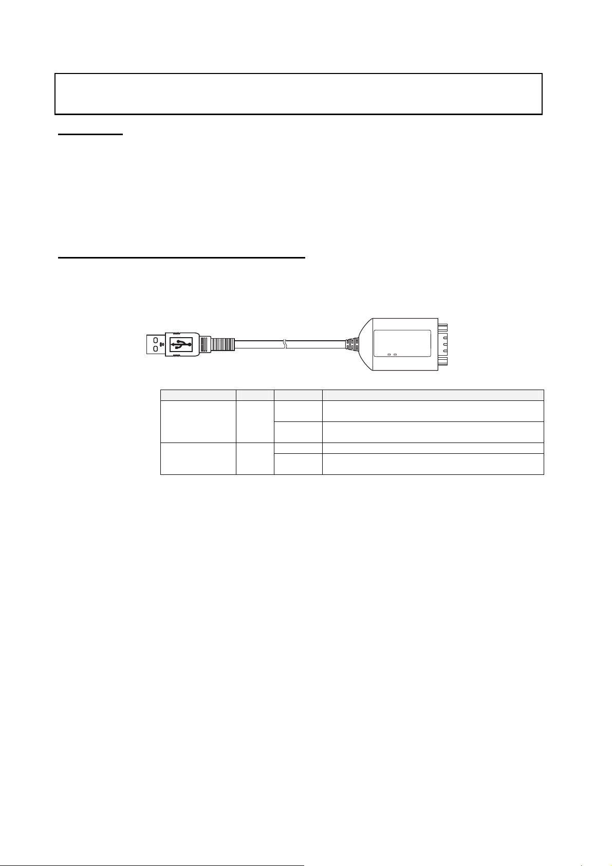
Appearance and Component Names
█ D-sub Connector Cable
● CS1W-CIF31 (USB Connector to D-sub Connector)
USB connector
(A plug connector, male)
D-Sub 9-pin connector (male)
LED Indicators
Indicator Color Status Description
TD Yellow
Flashing Data is being sent from the USB-Serial Conversion
Cable.
OFF Data is not being sent from the USB-Serial Conversion
Cable.
Flashing The USB-Serial Conversion Cable is receiving data. RD Yellow
OFF The USB-Serial Conversion Cable is not receiving
data.
8
Page 10

Packing Lists
D-sub Connector Cable (CS1W-CIF31)
Name Appearance
CS1W-CIF31
(USB Connector to D-sub Connector
Conversion Cable)
Drivers
(On CD-ROM)
User's Manual (this manual)
(On CD-ROM in PDF format)
Instruction Sheet
Packing Lists
9
Page 11

Specifications
Specifications
Compatible Operating Systems
Windows 98/ME/2000/XP/Vista
Compatible Software Applications
The compatible software applications communicate with the PLC using the CX-Server
or FinsGateway. The following software applications use CX-Server or FinsGateway.
Name Communications software
CX-Programmer CX-Server (FinsGateway is used for network communications.)
CX-Simulator FinsGateway
CX-Protocol CX-Server (FinsGateway is used for network communications.)
CX-Position FinsGateway
CX-Motion CX-Server
CX-Process FinsGateway or CX-Server
NS-Designer FinsGateway
PLC Reporter FinsGateway
The following software applications are also compatible.
• DeviceNet Configurator
• NT Support Tool for Windows
• ZEN Support Software Ver. 3.0 or later
• Software applications in CX-One
• Communications Port Limitations with the NT Support Tool
1) Version 4.00 and Earlier Versions
Only communications ports COM1 and COM2 can be used. Always change the
communications port allocation for this device to COM1 or COM2 in the Microsoft
Windows Device Manager (see note 1) and specify that port in the NT Support Tool's
communications settings. Once the communications port is specified correctly in the
Windows Device Manager and the NT Support Tool's communications settings, data
such as screen data can be downloaded to the PT or uploaded from the PT through the
USB-Serial Conversion Cable.
Note: In most personal computers, COM1 is allocated to the RS-232C port and
communications port COM2 can be allocated to the Conversion Cable. Refer to
Changing the Allocated Communications Port on page 36 for details on changing the
communications port. Furthermore, if there is another driver using the allocated port,
that driver must be uninstalled.
2) Version 4.60E and Later Versions
Any communications port between COM 1 and COM8 can be used. Check the NT
Support Tool's communications settings and verify that the communications port
allocated to the Conversion Cable is also specified in the NT Support Tool.
10
Page 12

• Limitations when Using the NT Support Tool's System Installer
1) Windows 98 and Windows Me
The system program cannot be downloaded to the PT through the USB-Serial
Conversion Cable.
2) Windows 2000, Windows XP, and Windows Vista
Only communications ports COM1 and COM2 can be used. Always change the
communications port allocation for this device to COM1 or COM2 in the Microsoft
Windows Device Manager (see note 1) and specify that port in the NT Support Tool's
communications settings. Once the communications port is specified correctly in the
Windows Device Manager and the NT Support Tool's communications settings, the
system program can be downloaded to the PT through the USB-Serial Conversion
Cable.
Note: In most personal computers, COM1 is allocated to the RS-232C port and
communications port COM2 can be allocated to the Conversion Cable. Refer to Changing
the Allocated Communications Port on page 36 for details on changing the communications
port. Furthermore, if there is another driver using the allocated port, that driver must be
uninstalled.
Compatible PLCs, PTs and Programmable Relay
The following OMRON PLCs, PTs and Programmable Relay are supported by the
compatible software applications.
• PLCs
CS/CJ-series, C-series (see note 1), and CVM1/CV-series
• PT
NS-series and NT-series
• Programmable Relay
ZEN (see note 2)
Note 1. The following C-series PLCs are supported: C200HS, C200HX/HG/HE, C200H, C1000H,
C2000H, CQM1, CPM1, CPM1A, CPM2A, SRM1, CQM1H, and CPM2C.
Note 2. The ZEN Programmable Relay is supported only if ZEN Support Software Ver. 3.0 or later
is used.
Specifications
11
Page 13

Specifications
Connection Configurations
The following table shows the connection configurations that can be used to connect an
OMRON PLC (or PT) to a personal computer's USB port.
USB-Serial
Conversion
Cable
CS1W-CIF31
(D-sub version)
Note The USB-Serial Conversion Cables are for connections between a USB port and an
OMRON PLC/PT only. In particular, the CS1W-CIF31 Cable can be used only with
compatible OMRON software applications even though it has a standard D-sub 9-pin
connector on one end.
Conversion
Cable's serial
connector
D-sub 9-pin
male
Required adapters or cables Compatible
•CS1W-CN226/626
(Programming Device Connecting Cable for a
CS/CJ-series peripheral port and personal
computer)
•XW2Z-200/500S-CV or XW2Z-200/500S-V
(Programming Device Connecting Cable for
an RS-232C port and personal computer)
PLC or PT
connector
CS/CJ-series
peripheral
port
+
•CS1W-CN118
(RS-232C to CS/CJ-series peripheral port
Conversion Cable)
•CQM1-CIF02
(Programming Device Connecting Cable for a
C-series peripheral port and personal
computer)
+
•CS1W-CN114
(C-series peripheral port to CS/CJ-series
peripheral port Conversion Cable)
•CQM1-CIF02
(Programming Device Connecting Cable for a
C-series peripheral port and personal
computer)
•RS-232C 9-pin to 25-pin adapter
+
•CV500-CIF01
(Programming Device Connecting Cable for a
CV-series peripheral port and PC98-type
personal computer)
•XW2Z-200/500S-CV or XW2Z-200/500S-V
(Programming Device Connecting Cable for
an RS-232C port and personal computer)
ZEN-CIF01
(Personal Computer Connecting Cable)
C-series
peripheral
port
CV-series
peripheral
port
RS-232C port
(D-sub 9-pin)
Personal
Computer
Connecting
port
Compatible PLCs
and PTs
CS/CJ-series,
CQM1H, and
CPM2C
C200HS,
C200HX/HG/HE,
CQM1, CPM1,
CPM1A, CPM2A,
and SRM1
CVM1/CV-series
PLCs (CPU Unit
or Serial
Communication
Unit/Board
connection) or
PTs
ZEN
12
Page 14

General Specifications
USB Interface rating Conforms to USB Specification 1.1
DTE speed 115.2 kbps
Power supply Bus power (5 VDC power from upstream)
Current consumption 35 mA
Operating
environment
Weight 50 g
Ambient temperature 0 to 55°C
Ambient humidity 10% to 90% humidity (with no condensation)
Atmosphere No corrosive gases
Specifications
Computer end USB (type A plug, male) Connector specifications
PLC end RS-232C (D-sub 9-pin, male)
13
Page 15

Dimensions
Dimensions
D-sub Connector Cable
█ CS1W-CIF31
72.4
6
35.8
17.8
500
(46) (11.75)
(12)
(8)
(4.5)
10
14
Page 16

System Configuration
CS/CJ-series PLCs
● Connecting to the Peripheral Port
• Using a CS1W-CN226/626 Cable
USB type A plug, male
CS1W-CIF31
D-sub Connector
(9-pin male)
D-sub Connector
(9-pin female)
CS/CJ-series PLC connection
Customizable Counter Unit connection
CS/CJ-series peripheral connector
System Configuration
Peripheral port
Recommended cable:
CS1W-CN226/626
• Using a CQM1-CIF02 Cable
USB type A plug, male
CS1W-CIF31
D-sub Connector
(9-pin male)
D-sub Connector
(9-pin female)
Recommended cable:
CQM1-CIF02
C-series peripheral connector
Note: With a CS/CJ-series PLC, the connection must be a host link connection.
CS/CJ-series PLC connection (see note)
CS/CJ-series peripheral
connector
Peripheral port
CS1W-CN114
15
Page 17

System Configuration
00S-V/500S
)
• Using a XW2Z-200S-CV/500S-CV or XW2Z-200S-V/500S-V Cable for an RS-232C
Connection
XW2Z-200S-CV/500S-CV
or
XW2Z-200S-V/500S-V (See note.)
Note: With a CS/CJ-series PLC, the connection must be a host link connection.
● Connecting to the RS-232C Port
USB type A plug, male
CS1W-CIF31
D-sub Connector
(9-pin male)
D-sub Connector
(9-pin female)
CS/CJ-series PLC connection
Customizable Counter Unit connection
D-sub Connector (9-pin male)
D-sub Connector
(9-pin female)
CS1W-CN118
CS/CJ-series peripheral connector
Peripheral port
• Using a XW2Z-200S-CV/500S-CV or XW2Z-200S-V/500S-V Cable for an RS-232C
Connection
USB type A plug, male
CS1W-CIF31
D-sub Connector
(9-pin male)
D-sub Connector
(9-pin female)
Recommended cable:
XW2Z-200S-CV/500S-CV
or
XW2Z-2
CS/CJ-series PLC connection
D-sub Connector
(9-pin male)
RS-232C port
D-sub Connector
(9-pin female)
-V(See note.
Note: With a CS/CJ-series PLC, the connection must be a host link connection.
16
Page 18

C-series PLCs
r
█ C200HS, C200HX/HG/HE, C200H, C1000H, C2000H, CQM1, CPM1, CPM1A,
CPM2A, or SRM1
• Connecting to the Peripheral Port
Using a CQM1-CIF02 Cable
System Configuration
USB type A plug, male
CS1W-CIF31
D-sub Connector
(9-pin male)
D-sub Connector
(9-pin female)
Recommended cable:
CQM1-CIF02
C-series PLC connection
C-series peripheral connector
Peripheral port
• Connecting to the RS-232C Port
Using a XW2Z-200S-CV/500S-CV or XW2Z-200S-V/500S-V Cable for an RS-232C
Connection
USB type A plug, male
CS1W-CIF31
D-sub Connector
(9-pin male)
D-sub Connector
(9-pin female)
C-series PLC connection
D-sub Connector
(9-pin male)
RS-232C port
D-sub Connecto
(9-pin female)
Recommended cable:
XW2Z-200S-CV/500S-CV
or
XW2Z-200S-V/500S-V
17
Page 19

System Configuration
█ CQM1H and CPM2C PLCs
• Connecting to the Peripheral Port
Using a CS1W-CN226/626 Cable
USB type A plug, male
CS1W-CIF31
D-sub Connector
(9-pin male)
D-sub Connector
(9-pin female)
CQM1H PLC connection
CPM2C PLC connection
CS/CJ-series peripheral connector
Peripheral port
Recommended cable:
CS1W-CN226/626
Using a CQM1-CIF02 Cable
USB type A plug, male
USB type A plug, male
CS1W-CIF31
D-sub Connector
(9-pin male)
CQM1H PLC connection
D-sub Connector
(9-pin female)
Recommended cable:
CQM1-CIF02
CPM2C PLC connection
C-series peripheral connector
CS1W-CN114
CS/CJ-series peripheral connector
Peripheral port
Note: With a CS/CJ-series PLC, the connection must be a host link connection.
18
Page 20

System Configuration
(9-p
)
r
Using a XW2Z-200S-CV/500S-CV or XW2Z-200S-V/500S-V Cable for an RS-232C
Connection
USB type A plug, male
CS1W-CIF31
D-sub Connector
(9-pin male)
D-sub Connector
(9-pin female)
XW2Z-200S-CV/500S-CV
or
XW2Z-200S-V/500S-V
(See note.)
Note: With a CS/CJ-series PLC, the connection must be a host link connection.
• Connecting to the RS-232C Port
CQM1H PLC connection
CPM2C PLC connection
D-sub Connector (9-pin male)
D-sub Connector
in female
CS1W-CN118
CS/CJ-series peripheral connecto
Peripheral port
Using a XW2Z-200S-CV/500S-CV or XW2Z-200S-V/500S-V Cable for an RS-232C
Connection
USB type A plug, male
CS1W-CIF31
D-sub Connector
(9-pin male)
D-sub Connector
(9-pin female)
XW2Z-200S-CV/500S-CV
or
XW2Z-200S-V/500S-V
(See note.)
CQM1H PLC connection
CPM2C PLC connection
D-sub Connector
(9-pin male)
RS-232C port
D-sub Connector
(9-pin female)
Note: With a CS/CJ-series PLC, the connection must be a host link connection.
19
Page 21

System Configuration
r
CVM1 and CV-series PLCs
● Connecting to the Peripheral Port
• Using a CV500-CIF01 Cable
USB type A plug, male
CS1W-CIF31
D-sub Connector
(9-pin male)
D-sub 25-pin (female) to
9-pin (female) Adapter
D-sub Connector
(25-pin male)
CVM1/CV-series PLC connection
CV-series peripheral connector
Recommended cable:
CV500-CIF01
● Connecting to the RS-232C Port
• Using a XW2Z-200S-V/500S-V Cable
USB type A plug, male
CS1W-CIF31
D-sub Connector
(9-pin male)
D-sub Connector
(9-pin female)
CVM1/CV-series PLC connection
D-sub Connector (9-pin male)
Peripheral port
RS-232C port
D-sub Connecto
(9-pin female)
Recommended cable:
XW2Z-200S-V/500S-V
20
Page 22

PTs (NS and NT Series)
● Connecting to the RS-232C Port
• Using a XW2Z-S002 Cable
USB type A plug, male
CS1W-CIF31
D-sub Connector
(9-pin male)
D-sub Connector
(9-pin female)
D-sub
Connector
(9-pin male)
System Configuration
PT connection
XW2Z-S002
Programmable Relay (ZEN)
USB type A plug, male
CS1W-CIF31
D-sub Connector
(9-pin mal e)
(9-pin fem ale)
Personal Computer
Connecting Cable
ZEN-CIF01
Personal Computer
Connector
RS-232C port
ZEND-sub Connector
Personal Computer
Connecting port
21
Page 23

USB to PLC/PT Connection Tables
USB to PLC/PT Connection Tables
Connecting with the CS1W-CIF31 (D-sub Connector Cable)
Computer CS1W-CIF31 Cable 1
CS1W-N226/626 Programming
Device Connecting Cable for a
CS/CJ-series peripheral por t
OR
CS1W-CIF31 USB
Conversion Cable
+
CQM1H-CIF02 Programming
Device Connecting Cable for a
C-series peripheral por t
XW2Z-@@@ Programming Device
Connecting Cable for RS-232C
OR
+
█ CS/CJ-series Units
CS1W-CN114
C-series peripheral por t to CS/CJ-series
peripheral port Conversion Cable
Cable 2
(when necessary)
CS1W-CN118
RS-232C to CS/CJ-series peripheral
port Conversion Cable
PLC
● CS/CJ-series CPU Units
USB
Conversion
Cable
Model Connector Model Connector Connector Model Connector (Network type)
CS1W-CIF31
Cable 1 Cable 2 Unit's port Serial
D-sub 9-pin,
female
D-sub 9-pin,
female
D-sub 9-pin,
female
D-sub 9-pin,
female
D-sub 9-pin,
female
D-sub 9-pin,
female
CS1W-CN226/626
(Length: 2 or 6 m)
CQM1-CIF02
(Length: 3.3 m)
XW2Z-200S-CV
/500S-CV
(Length: 2 or 5 m)
XW2Z-200S-V
/500S-V
(Length: 2 or 5 m)
XW2Z-200S-CV
/500S-CV
(Length: 2 or 5 m)
XW2Z-200S-V
/500S-V
(Length: 2 or 5 m)
CS/CJ-series
peripheral
C-series
peripheral
D-sub 9-pin,
male
D-sub 9-pin,
male
RS-232C
D-sub 9-pin,
male
RS-232C
D-sub 9-pin,
male
C-series
peripheral
D-sub 9-pin,
female
D-sub 9-pin,
female
Not necessary Peripheral bus
CS1W-CN114
(Length: 5 cm)
CS1W-CN118
(Length: 0.1 m)
CS1W-CN118
(Length: 0.1 m)
Not necessary Peripheral bus
Not necessary
CS/CJ-series
peripheral
CS/CJ-series
peripheral
CS/CJ-series
peripheral
CS/CJ-series
peripheral
RS-232C
D-sub 9-pin,
female
communications
mode
(Toolbus) or Host
link (SYSWAY)
Host link
(SYSWAY)
Peripheral bus
(Toolbus) or Host
link (SYSWAY)
Host link
(SYSWAY)
(Toolbus) or Host
link (SYSWAY)
Host link
(SYSWAY)
22
Page 24

USB to PLC/PT Connection Tables
● CS/CJ-series Serial Communications Board or Unit
USB
Conversion
Cable
Model Connector Model Connector Connector Model Connector (Network type)
CS1W-CIF31
Cable 1 Cable 2 Unit's port Serial
D-sub 9-pin,
female
D-sub 9-pin,
female
XW2Z-200S-CV
/500S-CV
(Length: 2 or 5 m)
XW2Z-200S-V
/500S-V
(Length: 2 or 5 m)
RS-232C
D-sub 9-pin,
male
RS-232C
D-sub 9-pin,
male
Not necessary Host link
Not necessary
RS-232C
D-sub 9-pin,
female
communications
mode
(SYSWAY)
● Customizable Counter Unit
USB
Conversion
Cable
Model Connector Model Connector Connector Model Connector (Network type)
CS1W-CIF31
█ C-series Units
Cable 1 Cable 2 Unit's port Serial
D-sub 9-pin,
female
D-sub 9-pin,
female
CS1W-CN226/626
(Length: 2 or 6 m)
XW2Z-200S-V
/500S-V
(Length: 2 or 5 m)
CS/CJ-series
peripheral
D-sub 9-pin,
male
D-sub 9-pin,
female
Not necessary Peripheral bus
CS1W-CN118
(Length: 0.1 m)
CS/CJ-series
peripheral
CS/CJ-series
peripheral
communications
(Toolbus)
Peripheral bus
(Toolbus)
Note: In this table, the C-series refers to the C200HS, C200HX/HG/HE, C200H, C1000H,
C2000H, CQM1, CPM1, CPM1A, CPM2A, SRM1, CQM1H, and CPM2C.
mode
● C200HS, C200HX/HG/HE, CQM1, CPM1, CPM1A, CPM2A, and SRM1
USB
Conversion
Cable
Model Connector Model Connector Connector Model Connector (Network type)
CS1W-CIF31
Cable 1 Cable 2 Unit's port Serial
D-sub 9-pin,
female
D-sub 9-pin,
female
D-sub 9-pin,
female
CQM1-CIF02
(Length: 3.3 m)
XW2Z-200S-CV
/500S-CV
(Length: 2 or 5 m)
XW2Z-200S-V
/500S-V
(Length: 2 or 5 m)
C-series
peripheral
D-sub 9-pin,
male
D-sub 9-pin,
male
Note: The host link mode can be used in all of these PLCs, but the peripheral bus mode cannot be
used in CPM2@ PLCs that have a 9 as the 4
Not necessary C-series
Not necessary Host link
Not necessary
th
digit of the lot number. (The lot number may be 4
peripheral
RS-232C
D-sub 9-pin,
female
communications
Peripheral bus
(Toolbus) or Host
link (SYSWAY)
(See note.)
(SYSWAY)
or 5 digits long.)
● C200H, C1000H, and C2000H CPU Units
USB
Conversion
Cable
Model Connector Model Connector Connector Model Connector (Network type)
CS1W-CIF31 D-sub 9-pin,
Cable 1 Cable 2 Unit's port Serial
female
CQM1-CIF02
(Length: 3.3 m)
C-series
peripheral
C-series
peripheral
C200H-IP007 Built-in peripheral port Host link
communications
(SYSWAY)
mode
mode
23
Page 25

USB to PLC/PT Connection Tables
● CQM1H CPU Units
USB
Conversion
Cable
Model Connector Model Connector Connector Model Connector (Network type)
CS1W-CIF31
Cable 1 Cable 2 Unit's port Serial
D-sub 9-pin,
female
D-sub 9-pin,
female
D-sub 9-pin,
female
D-sub 9-pin,
female
D-sub 9-pin,
female
D-sub 9-pin,
female
CS1W-CN226/626
(Length: 2 or 6 m)
CQM1-CIF02
(Length: 3.3 m)
XW2Z-200S-CV
/500S-CV
(Length: 2 or 5 m)
XW2Z-200S-V
/500S-V
(Length: 2 or 5 m)
XW2Z-200S-CV
/500S-CV
(Length: 2 or 5 m)
XW2Z-200S-V
/500S-V
(Length: 2 or 5 m)
● CPM2C
USB
Conversion
Cable
Model Connector Model Connector Connector Model Connector (Network type)
CS1W-CIF31
Cable 1 Cable 2 Unit's port Serial
D-sub 9-pin,
female
D-sub 9-pin,
female
D-sub 9-pin,
female
D-sub 9-pin,
female
D-sub 9-pin,
female
D-sub 9-pin,
female
D-sub 9-pin,
female
CQM1-CIF02
(Length: 3.3 m)
CQM1-CIF02
(Length: 3.3 m)
CS1W-CN226/626
(Length: 2 or 6 m)
(See note 2.)
XW2Z-200S-CV
/500S-CV
(Length: 2 or 5 m)
XW2Z-200S-CV
/500S-CV
(Length: 2 or 5 m)
XW2Z-200S-V
/500S-V
(Length: 2 or 5 m)
XW2Z-200S-V
/500S-V
(Length: 2 or 5 m)
Note 1: The host link mode can be used in all of these PLCs, but the peripheral bus mode cannot
be used in CPM2@ PLCs that have a 9 as the 4
may be 4 or 5 digits long.)
Note 2: Only host link mode can be used.
CS/CJ-series
peripheral
C-series
peripheral
D-sub 9-pin,
male
D-sub 9-pin,
male
D-sub 9-pin,
male
D-sub 9-pin,
male
C-series
peripheral
C-series
peripheral
CS/CJ-series
peripheral
D-sub 9-pin,
male
D-sub 9-pin,
male
D-sub 9-pin,
male
D-sub 9-pin,
male
C-series
peripheral
D-sub 9-pin,
female
D-sub 9-pin,
female
C-series
peripheral
C-series
peripheral
D-sub 9-pin,
female
D-sub 9-pin,
female
D-sub 9-pin,
female
D-sub 9-pin,
female
communications
mode
Not necessary Peripheral bus
CS1W-CN114
(Length: 5 cm)
CS1W-CN118
(Length: 0.1 m)
CS1W-CN118
(Length: 0.1 m)
Not necessary Host link
Not necessary
CS1W-CN114
(Length: 5 cm)
CPM2C-CN111
(Peripheral port
connector)
Not necessary
CS1W-CN118
(Length: 0.1 m)
CPM2C-CN111
(RS-232C port
connector)
CS1W-CN118
(Length: 0.1 m)
CPM2C-CN111
(RS-232C port
connector)
th
digit of the lot number. (The lot number
CS/CJ-series
peripheral
CS/CJ-series
peripheral
CS/CJ-series
peripheral
CS/CJ-series
peripheral
CS/CJ-series
peripheral
CS/CJ-series
peripheral
CS/CJ-series
peripheral
CS/CJ-series
peripheral
CS/CJ-series
peripheral
CS/CJ-series
peripheral
RS-232C
D-sub 9-pin,
female
CS/CJ-series
peripheral
RS-232C
D-sub 9-pin,
female
Peripheral bus
(Toolbus) or Host
link (SYSWAY)
(See note 1.)
Host link
(SYSWAY)
Host link
(SYSWAY)
(Toolbus) or Host
link (SYSWAY)
Host link
(SYSWAY)
(SYSWAY)
communications
mode
24
Page 26

USB to PLC/PT Connection Tables
● C-series Host Link Unit (C200H-LK201-V1 or C120-LK201-V1)
Note: The Host Link Unit cannot be used to connect a Programming Device (such as the
CX-Programmer) to a C200HX/HG/HE with the "-ZE" suffix at the end of the model number.
USB
Conversion
Cable
Model Connector Model Connector Connector Model Connector (Network type)
CS1W-CIF31 D-sub 9-pin,
Cable 1 Cable 2 Unit's port Serial
female
XW2Z-200P-V
/500P-V
(Length: 2 or 5 m)
D-sub 25-pin,
male
Not necessary RS-232C
D-sub
25-pin,
female
communications
mode
Host link
(SYSWAY)
● C-series Communications Board (C200HX/HG/HE PLCs Only)
USB
Conversion
Cable
Model Connector Model Connector Connector Model Connector (Network type)
CS1W-CIF31
Cable 1 Cable 2 Unit's port Serial
D-sub 9-pin,
female
D-sub 9-pin,
female
XW2Z-200S-CV
/500S-CV
(Length: 2 or 5 m)
XW2Z-200S-V
/500S-V
(Length: 2 or 5 m)
D-sub 9-pin,
male
D-sub 9-pin,
male
Not necessary Host link
Not necessary
RS-232C
D-sub
9-pin,
female
communications
mode
(SYSWAY)
● C200H, C1000H, and C2000H Host Link Units
Note: The C500-LK203 and C500-LK 201-V1 Host Link Units can be used with the C1000H and
C2000H. The C200H-LK201-V1 and C120-LK201-V1 Host Link Units can be used with the
C200H.
USB
Conversion
Cable
Model Connector Model Connector Connector Model Connector (Network type)
CS1W-CIF31 D-sub 9-pin,
Cable 1 Cable 2 Unit's port Serial
female
XW2Z-200P-V
/500P-V
(Length: 2 or 5 m)
D-sub 25-pin,
male
Not necessary RS-232C
D-sub
25-pin,
female
communications
mode
Host link
(SYSWAY)
● CQM1H Serial Communication Board
USB
Conversion
Cable
Model Connector Model Connector Connector Model Connector (Network type)
CS1W-CIF31
D-sub 9-pin,
female
D-sub 9-pin,
female
Cable 1 Cable 2 Unit's port Serial
XW2Z-200S-CV
/500S-CV
(Length: 2 or 5 m)
XW2Z-200S-V
/500S-V
(Length: 2 or 5 m)
D-sub 9-pin,
male
D-sub 9-pin,
male
Not necessary Host link
Not necessary
RS-232C
D-sub
9-pin,
female
communications
(SYSWAY)
mode
25
Page 27

USB to PLC/PT Connection Tables
█ CVM1 and CV-series
● CVM1 and CV-series CPU Units
USB
Conversion
Cable
Model Connector Model Connector Connector Model Connector (Network type)
CS1W-CIF31
Cable 1 Cable 2 Unit's port Serial
D-sub 9-pin,
female
D-sub 9-pin,
female
D-sub 25-pin (female)
to D-sub 9-pin
(female) adapter
XW2Z-200S-V
/500S-V
(Length: 2 or 5 m)
● CVM1 and CV-series Host Link Units
• CV500-LK201 (Port 1, Full-duplex mode)
USB
Conversion
Cable
Model Connector Model Connector Connector Model Connector (Network type)
CS1W-CIF31 D-sub 9-pin,
• CV500-LK201 (Port 2, Full-duplex mode)
USB
Conversion
Cable
Model Connector Model Connector Connector Model Connector (Network type)
CS1W-CIF31 D-sub 9-pin,
█ PTs (NS or NT Series)
USB
Conversion
Cable
Model Connector Model Connector Connector Model Connector (Network type)
CS1W-CIF31 D-sub 9-pin,
█ Programmable Relay (ZEN)
USB
Conversion
Cable
Model Connector Model Connector Connector Model Connector (Network type)
CS1W-CIF31 D-sub 9-pin,
Cable 1 Cable 2 Unit's port Serial
female
female
female
female
XW2Z-200P-V
/500P-V
(Length: 2 or 5 m)
Cable 1 Cable 2 Unit's port Serial
XW2Z-200S-V
/500S-V
(Length: 2 or 5 m)
Cable 1 Cable 2 Unit's port Serial
XW2Z-S002
(Length: 2 m)
Cable 1 Cable 2 Unit's port Serial
ZEN-CIF01
(Length: 2 m)
D-sub 25-pin,
male
D-sub 9-pin,
male
D-sub 25-pin,
male
D-sub 9-pin,
male
D-sub 9-pin,
male
Personal
Computer
Connector
D-sub 25-pin,
female
CV500-CIF01
(Length: 6 m)
Not necessary RS-232C
Not necessary RS-232C
Not necessary RS-232C
Not necessary RS-232C
Not necessary Personal
CV-series
peripheral
CV-series
peripheral
D-sub
9-pin,
female
D-sub
25-pin,
female
D-sub
9-pin,
female
D-sub
9-pin,
female
Computer
port
communications
Peripheral bus
(Toolbus)
Host link
(SYSWAY)
communications
Host link
(SYSWAY)
communications
Host link
(SYSWAY)
communications
Host link
(SYSWAY)
communications
-
mode
mode
mode
mode
mode
26
Page 28

Application Procedure
This section explains how to connect a PLC CPU Unit to a personal computer with a
USB-Serial Conversion Cable. Use the procedure below when connecting a PLC CPU
Unit and personal computer.
The Conversion Cable uses one of the computer's COM ports for communications.
When communicating with a PLC through a Conversion Cable, set the communications
port (COM port) number used by the software to the communications port (COM port)
number allocated to the Conversion Cable.
1. Connect the Cable(s).
Connect the Conversion Cable to the computer's USB port and the CPU Unit's
peripheral port or RS-232C port.
For details, refer to Connecting the Cable on page 28.
2. Install the communications driver.
The Conversion Cable's communications driver must be installed in the computer in
order for the computer to use the Conversion Cable.
For details, refer to Installing the Driver on page 29.
3. Turn ON the PLC's power.
Turn ON the PLC's power supply.
4. Make an online connection to the CPU Unit through the computer software (when
using the CX-Programmer.)
Select the COM port in the CPU Unit from the CX-Programmer and connect online.
For details, refer to Connecting Online from the CX-Programmer on page 34.
Note More than one USB-Serial Conversion Cable can be used at a time, so a single
personal computer can be connected to several PLCs/PTs through two or more COM
ports.
When more than one Conversion Cable is being used, connect the second and later
Cables after the first Cable has been connected.
The communications driver is automatically installed for the second and later Cables,
so it is not necessary to install the driver a second time. Each Cable must have its own
unique COM port number. Allocate a different COM port to each Cable.
Application Procedure
27
Page 29

Cable Connections
Cable Connections
Connecting the Cable
Connect the computer and CPU Unit with one of the cable configurations shown in the
USB to PLC/PT Connection Tables on page 22.
28
Page 30

Installing the Drivers
When the USB-Serial Conversion Cable is connected to the computer, the operating
system (OS) will recognize the Cable as a new device. At this point, the driver can be
installed with the wizard.
The actual driver installation method depends on the OS being used. Windows 2000 is
used in the examples in this section.
Note The USB-Serial Conversion Cables are compatible with Windows XP.
When you install the Conversion Cable's driver, a warning message will appear
indicating that the driver software has not passed W indows Logo testing, but click
Continue Anyway to proceed with the installation. We have thoroughly tested the
driver on Windows XP and verified the it operates properly.
The driver will not be installed properly if the installation process is cancelled before
completion. Normal communications may not be possible if the driver is not installed
properly. If the driver is not installed properly, uninstall it (refer to page 33) and then
reinstall it correctly.
Note The USB-Serial Conversion Cables are compatible with Windows Vista.
When you install the Conversion Cable's driver, a warning message will appear
indicating that Windows can’t verify the publisher of this driver software, but click
Continue Anyway to proceed with the installation. We have thoroughly tested the
driver on Windows Vista and verified that it operates properly.
The driver will not be installed properly if the installation process is cancelled before
completion. Normal communications may not be possible if the driver is not installed
properly. If the driver is not installed properly, uninstall it (refer to page 33) and then
reinstall it correctly.
1. The following window will be displayed.
Installing the Drivers
2. The following window will be displayed. Click the Next button.
The following window will be displayed.
29
Page 31

Installing the Drivers
3. Select Search for a suitable driver for my device (recommended) and click the Next
button.
The following window will be displayed.
Select Specify a location and click the Next button.
The following window will be displayed.
4. Insert the CD-ROM containing the driver (the CD-ROM is in the same package as
the Conversion Cable) into the computer's CD-ROM drive. Click the Browse button,
select the ftdibus.inf file, from the following directory of the CD-ROM and click the
OK button.
Windows2000/XP/Vista: win2000_XP
Windows98/Me: win98_Me
If the window's Copy manufacturer's files from field shows the correct folder, click the
OK button.
5. The following window will be displayed. Click the Next button to start the installing
the driver.
30
Page 32
Installing the Drivers
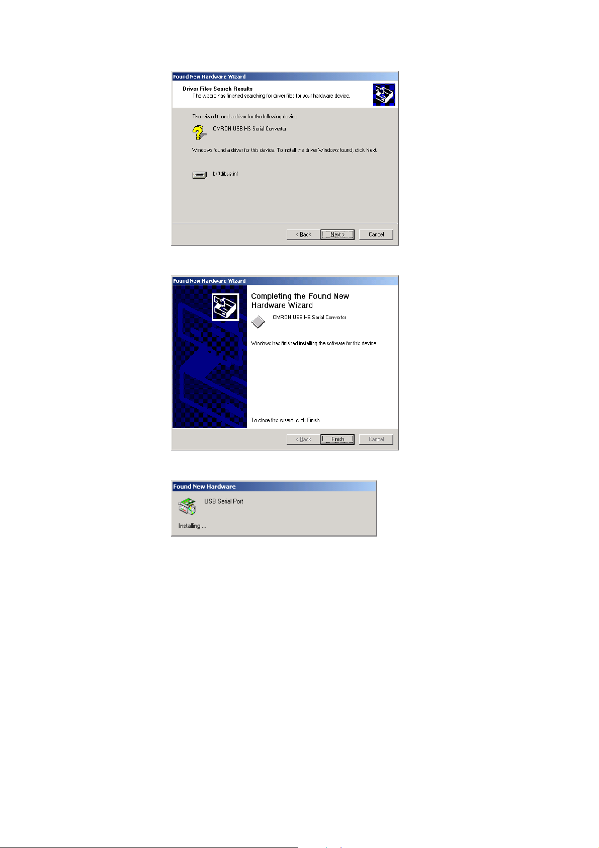
6. The following window will be displayed if the driver was installed properly. Click the
Finish button.
7. When the Finish button is clicked in step 6, the following window will be displayed for
installation of the USB Serial Port driver.
Follow the same procedure in steps 1 through 7 to install the USB Serial Port driver.
(Driver installation is completed after installation of the USB Serial Port driver.)
8. Verify that the drivers were installed properly with the Windows Device Manager, as
shown in the following diagram. To access the Device Manager, open the Control
Panel, open the System folder, click the Hardware tab, and click the Device
Manager button.
31
Page 33

Installing the Drivers
Verify that these two devices appear in the
Device Manager.
32
Page 34

Uninstalling the Drivers
Use the following procedure to delete (uninstall) the drivers for the USB-Serial
Conversion Cable.
1. Disconnect the Conversion Cable from the computer.
2. Select Add/Remove Programs from the Control Panel.
Uninstalling the Drivers
3. Select OMRON USB-to-Serial Converter Drivers and click the Delete button.
The following window will be displayed.
4. Click the Continue button.
When the drivers have been successfully deleted, the message Uninstall complete,
press Finish to exit will be displayed.
5. Click the Finish button.
This completes the deletion (uninstallation) of the Conversion Cable's drivers.
33
Page 35

Connecting Online from the CX-Programmer
Connecting Online from the CX-Programmer
The USB-Serial Conversion Cable uses one of the computer's COM ports to
communicate. The communications port (COM port) allocated to the Conversion Cable
must be selected with the CX-Programmer in order to connect online to a PLC or PT.
Note: It may take some time for the computer to detect the cable after the cable is connected. This
is not a malfunction.
█ Selecting the Cable's COM Port in CX-Programmer
Use the following procedure to select the COM port used by the Conversion Cable.
1. Display the Change PLC dialog box.
2. Click the Settings button in the Network Type area. Select the desired type of
network.
The Network Settings dialog box will be displayed.
3. Click the Driver tab in the Network Settings dialog box.
34
Page 36

Connecting Online from the CX-Programmer
4. Locate the Port Name setting and select the COM port being used by the Conversion
Cable.
Note
If you fail to connect with this USB Cable, turn OFF auto baud rate
detection if it is being used by your software. With the CX-Programmer,
auto baud rate detection can be turned OFF by clearing the selection for
it on the Network Settings dialog box.
█ Verifying the Allocated Communications Port
The communications port (COM port) being used by the Conversion Cable can be
verified with the following procedure. The actual verification procedure depends on the
operating system. This example shows the procedure for Windows 2000.
1. Open the Control Panel, open the System folder, and click the Hardware tab.
2. Click the Device Manager button.
3. Click the + symbol to the left of the Ports (COM & LPT) device icon to display the
contents of that folder. Verify that there is an entry for the OMRON CS1W-CIF3
USB Serial Port (COM
A communications port name will appear in parentheses. This is the communications
port being used by the Conversion Cable.
@
) device.
*
35
Page 37

Connecting Online from the CX-Programmer
█ Changing the Allocated Communications Port
The communications port (COM port) being used by the Conversion Cable can be
changed with the following procedure. The actual change procedure depends on the
operating system. This example shows the procedure for Windows 2000.
Note If the new COM port is being used by another driver, that driver must be uninstalled.
1. Double-click OMRON CS1W-CIF3* USB Serial Port (COM
window.
@
) in the Device Manager
2. Click the Port Settings tab.
36
Page 38

Connecting Online from the CX-Programmer
3. Click the Advanced button. The following window will be displayed.
4. Select the new COM port number from the COM Port Number list.
5. Click the OK button to change the COM port used by the Conversion Cable.
37
Page 39

Using More than One Conversion Cable
Using More than One Conversion Cable
The operating system recognizes USB-Serial Conversion Cables individually.
If a second Conversion Cable is connected after the driver has been installed, driver
installation will be requested again. Install the driver from the CD-ROM again.
If you do not own the CD-ROM and will use more than one Conversion Cable, copy the
win2000_XP folder from the CD-ROM to a folder on your hard disk, and select this
folder.
Note: Use the following directory for Windows 98 or Me: Win98_Me
1. Copy the win2000_XP folder from the CD-ROM to your hard disk (the CD-ROM is in
the same package as the Conversion Cable).
2. The following window will be displayed.
Select Install from a list or specific location (Advanced) and click the Next button.
3. Click the Browse button next to the Include this location in the search field, select
the win2000_XP folder copied from CD-ROM onto your hard disk, and click the Next
button.
38
Page 40

Revision History
Revision History
A manual revision code appears as a suffix to the catalog number on the front cover of the manual.
Cat. No. W417-E1-03
Revision code
The following table outlines the changes made to the manual during each revision. Page numbers
refer to the previous version.
Revision code Date Revised content
01 February 2003 Original production
02 October 2006 Page 7: Changed EMI standard number of EC Directives.
Page 30: Changed the reference directory for the driver file.
Page 37: Add section on using more than one Conversion Cable.
03 July 2007 Page 10: Changed the compatible operating systems.
Page 29: Changed information on installing the drivers.
39
Page 41

Index
Index
communications port
component names.......................................................................................................... 8
configuration, PLC/PT connections
CX-Programmer
C
changing............................................................................................................. 36
verifying .............................................................................................................. 35
C200HS, C200HX/HG/HE, C200H, C1000H/2000H, CQM1, CPM1, CPM1A,
CPM2A, and SRM1............................................................................................ 17
CQM1H, CPM2C................................................................................................ 18
CS/CJ-series PLCs ............................................................................................ 15
C-series PLCs .................................................................................................... 17
CVM1 and CV-series PLCs ............................................................................... 20
NS-series and NT-series PTs ............................................................................21
Programmable Relay (ZEN)............................................................................... 21
communications port .......................................................................................... 34
D
dimensions ................................................................................................................... 14
drivers
installing ............................................................................................................. 29
uninstalling ...................................................................................................33, 38
O
operating system, applicable........................................................................................ 10
overview ......................................................................................................................... 8
P
PLCs, applicable .......................................................................................................... 11
PTs, applicable ............................................................................................................. 11
S
software, applicable...................................................................................................... 10
40
Page 42

OMRON Corporation
Control Devices Division H.Q.
Shiokoji Horikawa, Shimogyo-ku,
Kyoto, 600-8530 Japan
Tel: (81)75-344-7109/Fax: (81)75-344-7149
Regional Headquarters
OMRON EUROPE B.V.
Wegalaan 67-69, NL-2132 JD Hoofddorp
The Netherlands
Tel: (31)2356-81-300/Fax: (31)2356-81-388
OMRON ELECTRONICS LLC
One Commerce Drive Schaumburg,
IL 60173-5302 U.S.A.
Tel: (1) 847-843-7900/Fax: (1) 847-843-7787
OMRON ASIA PACIFIC PTE. LTD.
No. 438A Alexandra Road # 05-05/08 (Lobby 2),
Alexandra Technopark, Singapore 119967
Tel: (65) 6835-3011/Fax: (65) 6835-2711
OMRON (CHINA) CO., LTD.
Room 2211, Bank of China Tower,
200 Yin Cheng Zhong Road,
Pu Dong New Area, Shanghai, 200120, China
Tel: (86) 21-5037-2222/Fax: (86) 21-5037-2200
Page 43

Authorized Distributor:
Cat. No. W417-E1-03
Note: Specifications subject to change without notice
Printed in Japan
 Loading...