

Page 1

Cat. No. W356-E1-08
SYSMAC
CPM2C
Programmable Controller
OPERATION MANUAL
Page 2

CPM2C Programmable Controller
Operation Manual
Revised February 2008
Page 3

iv
Page 4

Notice:
r
f
OMRON products are manufactured for use according to proper procedures by a qualified operator
and only for the purposes described in this manual.
The following conventions are used to indicate and classify precautions in this manual. Always heed
the information provided with them. Failure to heed precautions can result in injury to people or damage to property.
!DANGER Indicates an imminently hazardous situation which, if not avoided, will result in death or
serious injury. Additionally, there may be severe property damage.
!WARNING Indicates a potentially hazardous situation which, if not avoided, could result in death or
serious injury. Additionally, there may be severe property damage.
!Caution Indicates a potentially hazardous situation which, if not avoided, may result in minor or
moderate injury, or property damage.
OMRON Product References
All OMRON products are capitalized in this manual. The word “Unit” is also capitalized when it refers to
an OMRON product, regardless of whether or not it appears in the proper name of the product.
The abbreviation “Ch,” which appears in some displays and on some OMRON products, often means
“word” and is abbreviated “Wd” in documentation in this sense.
The abbreviation “PC” means Programmable Controller and is not used as an abbreviation for anything
else.
Visual Aids
The following headings appear in the left column of the manual to help you locate different types of
information.
OMRON, 1999
All rights reserved. No part of this publication may be reproduced, stored in a retrieval system, or transmitted, in any form, o
by any means, mechanical, electronic, photocopying, recording, or otherwise, without the prior written permission o
OMRON.
No patent liability is assumed with respect to the use of the information contained herein. Moreover, because OMRON is constantly striving to improve its high-quality products, the information contained in this manual is subject to change without
notice. Every precaution has been taken in the preparation of this manual. Nevertheless, OMRON assumes no responsibility
for errors or omissions. Neither is any liability assumed for damages resulting from the use of the information contained in
this publication.
Note Indicates information of particular interest for efficient and convenient opera-
tion of the product.
1,2,3... 1. Indicates lists of one sort or another, such as procedures, checklists, etc.
v
Page 5

vi
Page 6

TABLE OF CONTENTS
PRECAUTIONS . . . . . . . . . . . . . . . . . . . . . . . . . . . . . . . . . . . xv
1 Intended Audience . . . . . . . . . . . . . . . . . . . . . . . . . . . . . . . . . . . . . . . . . . . . . . . . . . . . . . . . xvi
2 General Precautions . . . . . . . . . . . . . . . . . . . . . . . . . . . . . . . . . . . . . . . . . . . . . . . . . . . . . . . xvi
3 Safety Precautions. . . . . . . . . . . . . . . . . . . . . . . . . . . . . . . . . . . . . . . . . . . . . . . . . . . . . . . . . xvi
4 Operating Environment Precautions . . . . . . . . . . . . . . . . . . . . . . . . . . . . . . . . . . . . . . . . . . . xviii
5 Application Precautions . . . . . . . . . . . . . . . . . . . . . . . . . . . . . . . . . . . . . . . . . . . . . . . . . . . .xviii
6 EC Directives . . . . . . . . . . . . . . . . . . . . . . . . . . . . . . . . . . . . . . . . . . . . . . . . . . . . . . . . . . . . xxi
SECTION 1
Introduction . . . . . . . . . . . . . . . . . . . . . . . . . . . . . . . . . . . . . . 1
1-1 CPM2C Features and Functions . . . . . . . . . . . . . . . . . . . . . . . . . . . . . . . . . . . . . . . . . . . . . . 2
1-2 System Configurations . . . . . . . . . . . . . . . . . . . . . . . . . . . . . . . . . . . . . . . . . . . . . . . . . . . . . 9
1-3 Structure and Operation . . . . . . . . . . . . . . . . . . . . . . . . . . . . . . . . . . . . . . . . . . . . . . . . . . . . 14
1-4 Functions Listed by Usage . . . . . . . . . . . . . . . . . . . . . . . . . . . . . . . . . . . . . . . . . . . . . . . . . .22
1-5 Comparison with the CPM1A and CPM2A . . . . . . . . . . . . . . . . . . . . . . . . . . . . . . . . . . . . . 24
1-6 Preparation for Operation . . . . . . . . . . . . . . . . . . . . . . . . . . . . . . . . . . . . . . . . . . . . . . . . . . . 31
1-7 Changes in SW2 . . . . . . . . . . . . . . . . . . . . . . . . . . . . . . . . . . . . . . . . . . . . . . . . . . . . . . . . . . 32
SECTION 2
Unit Components and Specifications . . . . . . . . . . . . . . . . . . 35
2-1 Specifications . . . . . . . . . . . . . . . . . . . . . . . . . . . . . . . . . . . . . . . . . . . . . . . . . . . . . . . . . . . . 36
2-2 Unit Components . . . . . . . . . . . . . . . . . . . . . . . . . . . . . . . . . . . . . . . . . . . . . . . . . . . . . . . . . 47
SECTION 3
Installation and Wiring . . . . . . . . . . . . . . . . . . . . . . . . . . . . . 83
3-1 Design Precautions . . . . . . . . . . . . . . . . . . . . . . . . . . . . . . . . . . . . . . . . . . . . . . . . . . . . . . . . 84
3-2 Selecting an Installation Site. . . . . . . . . . . . . . . . . . . . . . . . . . . . . . . . . . . . . . . . . . . . . . . . . 85
3-3 Installing the CPM2C . . . . . . . . . . . . . . . . . . . . . . . . . . . . . . . . . . . . . . . . . . . . . . . . . . . . . . 86
3-4 Wiring and Connections . . . . . . . . . . . . . . . . . . . . . . . . . . . . . . . . . . . . . . . . . . . . . . . . . . . .89
SECTION 4
Using a Programming Console . . . . . . . . . . . . . . . . . . . . . . . 151
4-1 Using a Programming Console . . . . . . . . . . . . . . . . . . . . . . . . . . . . . . . . . . . . . . . . . . . . . . . 152
4-2 Programming Console Operations . . . . . . . . . . . . . . . . . . . . . . . . . . . . . . . . . . . . . . . . . . . . 160
4-3 Programming Example . . . . . . . . . . . . . . . . . . . . . . . . . . . . . . . . . . . . . . . . . . . . . . . . . . . . . 185
vii
Page 7

TABLE OF CONTENTS
SECTION 5
Test Runs and Error Processing . . . . . . . . . . . . . . . . . . . . . . 193
5-1 Initial System Checks and Test Run Procedure . . . . . . . . . . . . . . . . . . . . . . . . . . . . . . . . . . 194
5-2 Self-diagnostic Functions . . . . . . . . . . . . . . . . . . . . . . . . . . . . . . . . . . . . . . . . . . . . . . . . . . . 195
5-3 Programming Console Operation Errors. . . . . . . . . . . . . . . . . . . . . . . . . . . . . . . . . . . . . . . . 198
5-4 Programming Errors . . . . . . . . . . . . . . . . . . . . . . . . . . . . . . . . . . . . . . . . . . . . . . . . . . . . . . . 198
5-5 Troubleshooting Flowcharts . . . . . . . . . . . . . . . . . . . . . . . . . . . . . . . . . . . . . . . . . . . . . . . . . 200
5-6 Maintenance Inspections. . . . . . . . . . . . . . . . . . . . . . . . . . . . . . . . . . . . . . . . . . . . . . . . . . . .208
5-7 Battery Replacement. . . . . . . . . . . . . . . . . . . . . . . . . . . . . . . . . . . . . . . . . . . . . . . . . . . . . . . 209
SECTION 6
Expansion Memory Unit . . . . . . . . . . . . . . . . . . . . . . . . . . . . 211
6-1 Overview. . . . . . . . . . . . . . . . . . . . . . . . . . . . . . . . . . . . . . . . . . . . . . . . . . . . . . . . . . . . . . . . 212
6-2 Specifications and Nomenclature . . . . . . . . . . . . . . . . . . . . . . . . . . . . . . . . . . . . . . . . . . . . . 213
6-3 Handling . . . . . . . . . . . . . . . . . . . . . . . . . . . . . . . . . . . . . . . . . . . . . . . . . . . . . . . . . . . . . . . . 214
SECTION 7
Simple Communications Unit . . . . . . . . . . . . . . . . . . . . . . . . 221
7-1 Introduction. . . . . . . . . . . . . . . . . . . . . . . . . . . . . . . . . . . . . . . . . . . . . . . . . . . . . . . . . . . . . . 222
7-2 Unit Components and Functions. . . . . . . . . . . . . . . . . . . . . . . . . . . . . . . . . . . . . . . . . . . . . . 228
7-3 Preparation for Operation . . . . . . . . . . . . . . . . . . . . . . . . . . . . . . . . . . . . . . . . . . . . . . . . . . . 233
7-4 Data Memory (DM) Allocation . . . . . . . . . . . . . . . . . . . . . . . . . . . . . . . . . . . . . . . . . . . . . . 237
7-5 DM Settings and Component Communications . . . . . . . . . . . . . . . . . . . . . . . . . . . . . . . . . . 254
7-6 Precautions for Component Communications . . . . . . . . . . . . . . . . . . . . . . . . . . . . . . . . . . . 255
7-7 Error Processing . . . . . . . . . . . . . . . . . . . . . . . . . . . . . . . . . . . . . . . . . . . . . . . . . . . . . . . . . . 256
7-8 Data Refresh Intervals (Reference Data) . . . . . . . . . . . . . . . . . . . . . . . . . . . . . . . . . . . . . . . 258
7-9 Example Application. . . . . . . . . . . . . . . . . . . . . . . . . . . . . . . . . . . . . . . . . . . . . . . . . . . . . . . 258
Appendices
A Standard Models . . . . . . . . . . . . . . . . . . . . . . . . . . . . . . . . . . . . . . . . . . . . . . . . . . . . . . . . . 267
B Dimensions . . . . . . . . . . . . . . . . . . . . . . . . . . . . . . . . . . . . . . . . . . . . . . . . . . . . . . . . . . . . . . 273
C DM Settings Assignment Sheets . . . . . . . . . . . . . . . . . . . . . . . . . . . . . . . . . . . . . . . . . . . . . 281
D SYSMAC and SYSMAC-CPT Support Software . . . . . . . . . . . . . . . . . . . . . . . . . . . . . . . . 289
Index . . . . . . . . . . . . . . . . . . . . . . . . . . . . . . . . . . . . . . . . . . . . 295
Revision History . . . . . . . . . . . . . . . . . . . . . . . . . . . . . . . . . . . 301
viii
Page 8

About this Manual:
The CPM2C is a compact, high-speed Programmable Controller (PC) designed for control operations
in systems requiring from 10 to 120 I/O points per PC. There are two manuals describing the setup and
operation of the CPM2C: The CPM2C Operation Manual (this manual) and the CPM1/CPM1A/
CPM2A/CPM2C/SRM1(-V2) Programming Manual (W353). (The CPM1/CPM1A/CPM2A/CPM2C/
SRM1(-V2) Programming Manual is referred to as simply the Programming Manual in this manual.)
This manual describes the system configuration and installation of the CPM2C and provides a basic
explanation of operating procedures for the Programming Consoles.
The Programming Manual (W353) provides detailed descriptions of the CPM2C’s programming func-
tions. The CX-Programmer Operation Manual (W437) provides details of operations for the WS02-
CXPC1-E CX-Programmer.
Please read this manual carefully and be sure you understand the information provided before
attempting to install and operate the CPM2C.
Section 1 gives a brief overview of the steps involved in developing of a CPM2C System, describes
the possible system configurations, and describes the CPM2C’s special features and functions.
Section 2 provides the technical specifications of the Units that go together to create a CPM2C PC
and describes the main components of the Units.
Section 3 describes how to install and wire a CPM2C PC.
Section 4 describes how to connect the Programming Console, and how to perform the various pro-
gramming operations.
Section 5 describes how to perform a test run and how to diagnose and correct the hardware and software errors that can occur during PC operation.
Section 6 describes how to use the CPM1-EMU01-V1 Expansion Memory Unit.
Section 7 describes the features and functions of the CPM2C-CIF21 Simple Communications Unit,
the settings required to use the Unit, and an example application. DM Settings Assignment Sheets are
provided in Appendix C to record data settings.
Appendix A provides tables of CPM2C Units and related products.
Appendix B provides the dimensions of CPM2C Units.
Appendix C provides DM setting assignment sheets for use with the CPM2C-CIF21 Simple Communi-
cations Unit.
Appendix D describes SYSMAC and SYSMAC-CPT Support Software capabilities and how to connect the CPM2C to the personal computer with this Support Software installed.
!WARNING Failure to read and understand the information provided in this manual may result in per-
sonal injury or death, damage to the product, or product failure. Please read each section
in its entirety and be sure you understand the information provided in the section and
related sections before attempting any of the procedures or operations given.
ix
Page 9

x
Page 10

Read and Understand this Manual
Please read and understand this manual before using the product. Please consult your OMRON
representative if you have any questions or comments.
Warranty and Limitations of Liability
WARRANTY
OMRON's exclusive warranty is that the products are free from defects in materials and workmanship for a
period of one year (or other period if specified) from date of sale by OMRON.
OMRON MAKES NO WARRANTY OR REPRESENTATION, EXPRESS OR IMPLIED, REGARDING NONINFRINGEMENT, MERCHANTABILITY, OR FITNESS FOR PARTICULAR PURPOSE OF THE
PRODUCTS. ANY BUYER OR USER ACKNOWLEDGES THAT THE BUYER OR USER ALONE HAS
DETERMINED THAT THE PRODUCTS WILL SUITABLY MEET THE REQUIREMENTS OF THEIR
INTENDED USE. OMRON DISCLAIMS ALL OTHER WARRANTIES, EXPRESS OR IMPLIED.
LIMITATIONS OF LIABILITY
OMRON SHALL NOT BE RESPONSIBLE FOR SPECIAL, INDIRECT, OR CONSEQUENTIAL DAMAGES,
LOSS OF PROFITS OR COMMERCIAL LOSS IN ANY WAY CONNECTED WITH THE PRODUCTS,
WHETHER SUCH CLAIM IS BASED ON CONTRACT, WARRANTY, NEGLIGENCE, OR STRICT
LIABILITY.
In no event shall the responsibility of OMRON for any act exceed the individual price of the product on which
liability is asserted.
IN NO EVENT SHALL OMRON BE RESPONSIBLE FOR WARRANTY, REPAIR, OR OTHER CLAIMS
REGARDING THE PRODUCTS UNLESS OMRON'S ANALYSIS CONFIRMS THAT THE PRODUCTS
WERE PROPERLY HANDLED, STORED, INSTALLED, AND MAINTAINED AND NOT SUBJECT TO
CONTAMINATION, ABUSE, MISUSE, OR INAPPROPRIATE MODIFICATION OR REPAIR.
xi
Page 11

Application Considerations
SUITABILITY FOR USE
OMRON shall not be responsible for conformity with any standards, codes, or regulations that apply to the
combination of products in the customer's application or use of the products.
At the customer's request, OMRON will provide applicable third party certification documents identifying
ratings and limitations of use that apply to the products. This information by itself is not sufficient for a
complete determination of the suitability of the products in combination with the end product, machine,
system, or other application or use.
The following are some examples of applications for which particular attention must be given. This is not
intended to be an exhaustive list of all possible uses of the products, nor is it intended to imply that the uses
listed may be suitable for the products:
• Outdoor use, uses involving potential chemical contamination or electrical interference, or conditions or
uses not described in this manual.
• Nuclear energy control systems, combustion systems, railroad systems, aviation systems, medical
equipment, amusement machines, vehicles, safety equipment, and installations subject to separate
industry or government regulations.
• Systems, machines, and equipment that could present a risk to life or property.
Please know and observe all prohibitions of use applicable to the products.
NEVER USE THE PRODUCTS FOR AN APPLICATION INVOLVING SERIOUS RISK TO LIFE OR
PROPERTY WITHOUT ENSURING THAT THE SYSTEM AS A WHOLE HAS BEEN DESIGNED TO
ADDRESS THE RISKS, AND THAT THE OMRON PRODUCTS ARE PROPERLY RATED AND
INSTALLED FOR THE INTENDED USE WITHIN THE OVERALL EQUIPMENT OR SYSTEM.
PROGRAMMABLE PRODUCTS
OMRON shall not be responsible for the user's programming of a programmable product, or any
consequence thereof.
xii
Page 12

Disclaimers
CHANGE IN SPECIFICATIONS
Product specifications and accessories may be changed at any time based on improvements and other
reasons.
It is our practice to change model numbers when published ratings or features are changed, or when
significant construction changes are made. However, some specifications of the products may be changed
without any notice. When in doubt, special model numbers may be assigned to fix or establish key
specifications for your application on your request. Please consult with your OMRON representative at any
time to confirm actual specifications of purchased products.
DIMENSIONS AND WEIGHTS
Dimensions and weights are nominal and are not to be used for manufacturing purposes, even when
tolerances are shown.
PERFORMANCE DATA
Performance data given in this manual is provided as a guide for the user in determining suitability and does
not constitute a warranty. It may represent the result of OMRON's test conditions, and the users must
correlate it to actual application requirements. Actual performance is subject to the OMRON Warranty and
Limitations of Liability.
ERRORS AND OMISSIONS
The information in this manual has been carefully checked and is believed to be accurate; however, no
responsibility is assumed for clerical, typographical, or proofreading errors, or omissions.
xiii
Page 13

xiv
Page 14

PRECAUTIONS
This section provides general precautions for using the Programmable Controller (PC) and related devices.
The information contained in this section is important for the safe and reliable application of the Programmable
Controller. You must read this section and understand the information contained before attempting to set up or
operate a PC system.
1 Intended Audience . . . . . . . . . . . . . . . . . . . . . . . . . . . . . . . . . . . . . . . . . . . . . xvi
2 General Precautions . . . . . . . . . . . . . . . . . . . . . . . . . . . . . . . . . . . . . . . . . . . . xvi
3 Safety Precautions. . . . . . . . . . . . . . . . . . . . . . . . . . . . . . . . . . . . . . . . . . . . . . xvi
4 Operating Environment Precautions . . . . . . . . . . . . . . . . . . . . . . . . . . . . . . . . xviii
5 Application Precautions . . . . . . . . . . . . . . . . . . . . . . . . . . . . . . . . . . . . . . . . . xviii
6 EC Directives . . . . . . . . . . . . . . . . . . . . . . . . . . . . . . . . . . . . . . . . . . . . . . . . . xxi
xv
Page 15

Intended Audience 1
1 Intended Audience
This manual is intended for the following personnel, who must also have
knowledge of electrical systems (an electrical engineer or the equivalent).
• Personnel in charge of installing FA systems.
• Personnel in charge of designing FA systems.
• Personnel in charge of managing FA systems and facilities.
2 General Precautions
The user must operate the product according to the performance specifications described in the operation manuals.
Before using the product under conditions which are not described in the
manual or applying the product to nuclear control systems, railroad systems,
aviation systems, vehicles, combustion systems, medical equipment, amusement machines, safety equipment, and other systems, machines, and equipment that may have a serious influence on lives and property if used
improperly, consult your OMRON representative.
Make sure that the ratings and performance characteristics of the product are
sufficient for the systems, machines, and equipment, and be sure to provide
the systems, machines, and equipment with double safety mechanisms.
This manual provides information for programming and operating the Unit. Be
sure to read this manual before attempting to use the Unit and keep this manual close at hand for reference during operation.
!WARNING It is extremely important that a PC and all PC Units be used for the specified
purpose and under the specified conditions, especially in applications that can
directly or indirectly affect human life. You must consult with your OMRON
representative before applying a PC System to the above-mentioned applications.
3 Safety Precautions
!WARNING Connect the ground terminal of the Power Supply Unit (CPM2C-PA201) to a
ground or 100
!WARNING Do not attempt to take any Unit apart while the power is being supplied. Doing
so may result in electric shock.
!WARNING Do not touch any of the terminals or terminal blocks while the power is being
supplied. Doing so may result in electric shock.
!WARNING Do not attempt to disassemble, repair, or modify any Units. Any attempt to do
so may result in malfunction, fire, or electric shock.
!WARNING Provide safety measures in external circuits (i.e., not in the Programmable
Controller), including the following items, in order to ensure safety in the system if an abnormality occurs due to malfunction of the PC or another external
factor affecting the PC operation. Not doing so may result in serious accidents.
Ω or less. Not doing so may result in electric shock.
xvi
• Emergency stop circuits, interlock circuits, limit circuits, and similar safety
measures must be provided in external control circuits.
Page 16

Safety Precautions 3
• The PC will turn OFF all outputs when its self-diagnosis function detects
any error or when a severe failure alarm (FALS) instruction is executed.
As a countermeasure for such errors, external safety measures must be
provided to ensure safety in the system.
• The PC outputs may remain ON or OFF due to deposition or burning of
the output relays or destruction of the output transistors. As a countermeasure for such problems, external safety measures must be provided
to ensure safety in the system.
• If the 24-VDC output (service power supply) of the Power Supply Unit
(CPM2C-PA201) is overloaded or shorted, the voltage may drop causing
outputs to turn OFF. External safety measures must be provided to
ensure safety in the system in such an event.
!WARNING When handling the Memory Backup Battery, never drop, disassemble, distort,
short-circuit, recharge, heat to a temperature exceeding 100
fire. Otherwise the Battery may explode, catch fire, or leak fluid.
!WARNING When transferring programs to other nodes, or when making changes to I/O
memory, confirm the safety of the destination node before transfer. Not doing
so may result in injury.
°C, or throw into
!Caution Execute online edit only after confirming that no adverse effects will be
caused by extending the cycle time. Otherwise, the input signals may not be
readable.
!Caution Tighten the screws on the terminal block of the Power Supply Unit (CPM2C-
PA201) to a torque of 0.74 to 0.9 N•m. Loose screws may result in burning or
malfunction.
!Caution Do not connect the 24-VDC output (service power supply) or the Power Sup-
ply Unit (CPM2C-PA201) to an AC power supply. Connecting it to an AC
power supply will damage the internal circuit.
!Caution When connecting a personal computer or other peripheral device to the
CPM2C, either ground the 0 V side of the CPM2C or do not ground at all.
Depending on the method of grounding, the 24-V power supply may short-circuit; do not ground the 24-V side as shown in the following diagram.
Example: Connections where 24-V Power Supply Will Short-circuit
Non-isolated DC
24 V
0 V 0 V
FG FG
power supply
0 V
CPM2C Peripheral device
xvii
Page 17

Operating Environment Precautions 4
4 Operating Environment Precautions
!Caution Do not operate the control system in the following places:
• Locations subject to direct sunlight.
• Locations subject to temperatures or humidity outside the range specified
in the specifications.
• Locations subject to condensation as the result of severe changes in temperature.
• Locations subject to corrosive or flammable gases.
• Locations subject to dust (especially iron dust) or salts.
• Locations subject to exposure to water, oil, or chemicals.
• Locations subject to shock or vibration.
!Caution Take appropriate and sufficient countermeasures when installing systems in
the following locations:
• Locations subject to static electricity or other forms of noise.
• Locations subject to strong electromagnetic fields.
• Locations subject to possible exposure to radioactivity.
• Locations close to power supplies.
!Caution The operating environment of the PC System can have a large effect on the
longevity and reliability of the system. Improper operating environments can
lead to malfunction, failure, and other unforeseeable problems with the PC
System. Be sure that the operating environment is within the specified conditions at installation and remains within the specified conditions during the life
of the system.
5 Application Precautions
Observe the following precautions when using the PC System.
!WARNING Always heed these precautions. Failure to abide by the following precautions
could lead to serious or possibly fatal injury.
• Always connect to a ground such that the grounding resistance does not
exceed 100
ground may result in electric shock.
• Always turn OFF the power supply to the PC before attempting any of the
following. Not turning OFF the power supply may result in malfunction or
electric shock.
• Assembling the Units.
• Connecting or disconnecting the Expansion I/O Units or Expansion
Units.
• Connecting or wiring the cables.
• Connecting or disconnecting the connectors.
• Setting DIP switches.
• Replacing the battery
Ω when installing the Units. Not connecting to the correct
xviii
Page 18

Application Precautions 5
!Caution Failure to abide by the following precautions could lead to faulty operation of
the PC or the system, or could damage the PC or PC Units. Always heed
these precautions.
• Fail-safe measures must be taken by the customer to ensure safety in the
event of incorrect, missing, or abnormal signals caused by broken signal
lines, momentary power interruptions, or other causes.
• Use the correct power supply voltage.
• Construct a control circuit so that power supply for the I/O circuits does
not come ON before power supply for the Unit. If power supply for the I/O
circuits comes ON before power supply for the Unit, normal operation may
be temporarily interrupted.
• If the operating mode is changed from RUN or MONITOR mode to PROGRAM mode, with the IOM Hold Bit ON, the output will hold the most
recent status. In such a case, ensure that the external load does not
exceed specifications. (If operation is stopped because of an operation
error (including FALS instructions), the values in the internal memory of
the CPU Unit will be saved, but the outputs will all turn OFF.)
• For models with only the super-capacitor installed, the contents of the
READ/WRITE enable area of the DM area, HR area, AR area, and CNT
data area may be damaged if the power is turned OFF for a long time. To
prevent such damage, provide ladder program that will check AR 1314 in
order to ensure proper operation of the system.
• The life expectancy of the output relay varies considerably according to its
switching capacity and switching conditions. If the output relay is used
beyond its life expectancy, its contacts may become fused or burned.
• Install the Units properly so that they will not fall off.
• Be sure that all the mounting screws, terminal screws, and cable connector screws are tightened to the torque specified in the relevant manuals.
Incorrect tightening torque may result in malfunction.
• Be sure that the terminal blocks and other items with locking devices are
properly locked into place. Improper locking may result in malfunction.
• Be sure that terminal blocks and connectors are connected in the specified direction with the correct polarity. Not doing so may result in malfunction. If the power supply for the I/O circuits is turned ON with the input and
output connectors reversed, the fuse of output transistor may be blown.
• Use the Unit with the battery housing cover in place to prevent dust or foreign matter from entering inside the Unit. Not doing so may result in malfunction.
• Install the expansion I/O connector cover to the last Unit (Expansion Unit
or Expansion I/O Unit) to prevent dust or foreign matter from entering
inside the Unit. Not doing so may result in malfunction.
• Be sure to attach the labels supplied with the CPM2C or provide other
protective covers when wiring in order to prevent dust or wiring cuttings
from entering the Unit.
• Remove the label after the completion of wiring to ensure proper heat dissipation. Leaving the label attached may result in malfunction.
• Use round crimp terminals for wiring the AC power supply input to the AC
Power Supply Unit (CPM2C-PA201). For wiring the ground terminals or
power supply service terminals, use crimp terminals or solid wires. Do not
connect bare stranded wires directly to terminals. Connection of bare
stranded wires may result in burning.
xix
Page 19

Application Precautions 5
• Be sure to perform wiring in accordance with the CPM2C Operation Manual. Incorrect wiring may result in burning.
• Use specified connectors and wiring materials (connector models: C500CE241/C500-CE242/C500-CE243; terminal block models: AWG28-16
with stripped length of 7 mm; Power Supply Unit terminal block: AWG2214 with stripped length of 7 mm).
• Do not apply voltages to the input terminals in excess of the rated input
voltage. Excess voltages may result in burning.
• Do not apply voltages or connect loads to the output terminals in excess
of the maximum switching capacity. Excess voltage or loads may result in
burning.
• Install external breakers and take other safety measures against short-circuiting in external wiring. Insufficient safety measures against short-circuiting may result in burning.
• Always use the power supply voltage specified in the operation manuals.
An incorrect voltage may result in malfunction or burning.
• Check the user program for proper execution before actually running it on
the Unit. Not checking the program may result in an unexpected operation.
• Double-check all wiring and switch settings before turning ON the power
supply. Incorrect wiring or switch settings may result in burning.
• Confirm that no adverse effect will occur in the system before attempting
any of the following. Not doing so may result in an unexpected operation.
• Changing the operating mode of the PC.
• Force-setting/force-resetting any bit in memory.
• Changing the present value of any word or any set value in memory.
• Before touching the Unit, be sure to first touch a grounded metallic object
in order to discharge any static built-up. Not doing so may result in malfunction or damage.
• Do not pull on the cables or bend the cables beyond their natural limit.
Doing either of these may break the cables.
• Do not apply forces exceeding 50 N to connector sections.
• Do not place objects on top of the cables. Doing so may break the cables.
• Resume operation only after transferring to the new CPU Unit the contents of the DM and HR Areas required for resuming operation. Not doing
so may result in an unexpected operation.
• Install the Unit properly as specified in the operation manual. Improper
installation of the Unit may result in malfunction.
• When transporting the Units, use special packing boxes. Be careful not to
apply excessive vibration or shock during transportation and not to drop
the product.
• Store the Units within the following temperature and humidity ranges:
Storage temperature: –20 to 75
icing or condensation)
• When using a thermocouple-input Temperature Sensor Unit, do not touch
the cold junction compensator. Doing so may result in incorrect temperature measurement.
°C, storage humidity: 10% to 90% (with no
xx
Page 20

EC Directives 6
6 EC Directives
6-1 Applicable Directives
•EMC Directives
• Low Voltage Directive
6-2 Concepts
EMC Directives
OMRON devices that comply with EC Directives also conform to the related
EMC standards so that they can be more easily built into other devices or the
overall machine. The actual products have been checked for conformity to
EMC standards (see the following note). Whether the products conform to the
standards in the system used by the customer, however, must be checked by
the customer.
EMC-related performance of the OMRON devices that comply with EC Directives will vary depending on the configuration, wiring, and other conditions of
the equipment or control panel on which the OMRON devices are installed.
The customer must, therefore, perform the final check to confirm that devices
and the overall machine conform to EMC standards.
Note Applicable EMC (Electromagnetic Compatibility) standards are as follows:
EMS (Electromagnetic Susceptibility): EN61131-2
EMI (Electromagnetic Interference): EN61000-6-4
Low Voltage Directive
Always ensure that devices operating at voltages of 50 to 1,000 VAC and 75
to 1,500 VDC meet the required safety standards for the PC (EN61131-2).
6-3 Conformance to EC Directives
The CPM2C PCs comply with EC Directives. To ensure that the machine or
device in which the CPM2C PC is used complies with EC Directives, the PC
must be installed as follows:
1,2,3... 1. The CPM2C PC must be installed within a control panel.
2. Reinforced insulation or double insulation must be used for the DC power
supplies used for the communications and I/O power supplies.
3. Basic insulation is provided between the commons of different polarities of
the output relay for the CPM2C-20@@R (model with 20 relay output
points).
When connecting devices that operate at voltages higher than 50 VAC and
those that operate on DC power supplies to adjoining relay output terminals, use different DC power supplies for output devices from those for input devices and the CPM2C power supply.
4. CPM2C PCs complying with EC Directives also conform to the Common
Emission Standard (EN61000-6-4). Radiated emission characteristics
(10-m regulations) may vary depending on the configuration of the control
panel used, other devices connected to the control panel, wiring, and other
conditions. You must therefore confirm that the overall machine or equipment complies with EC Directives.
(Radiated emission: 10-m regulations)
xxi
Page 21

EC Directives 6
6-4 Relay Output Noise Reduction Methods
The CPM2C PCs conform to the Common Emission Standards (EN61000-6-
4) of the EMC Directives. However, the noise generated when the PC is
switched ON or OFF using the relay output may not satisfy these standards. In
such a case, a noise filter must be connected to the load side or other appropriate countermeasures must be provided external to the PC.
Countermeasures taken to satisfy the standards vary depending on the
devices on the load side, wiring, configuration of machines, etc. Following are
examples of countermeasures for reducing the generated noise.
Countermeasures
(Refer to EN61000-6-4 for more details.)
Countermeasures are not required if the frequency of load switching for the
whole system with the PC included is less than 5 times per minute.
Countermeasures are required if the frequency of load switching for the whole
system with the PC included is 5 times or more per minute.
Countermeasure Examples
When switching an inductive load, connect a surge protector, diodes, etc., in
parallel with the load or contact as shown below.
Circuit Current Characteristic Required element
AC DC
CR method
Powe r
supply
Yes Yes If the load is a relay or solenoid, there
Inductive
load
is a time lag between the moment the
circuit is opened and the moment the
load is reset.
If the supply voltage is 24 to 48 V,
insert the surge protector in parallel
with the load. If the supply voltage is
100 to 200 V, insert the surge protector
between the contacts.
The capacitance of the capacitor must
be 1 to 0.5 µF per contact current of
1 A and resistance of the resistor must
be 0.5 to 1 Ω per contact voltage of 1 V.
These values, however, vary with the
load and the characteristics of the
relay. Decide these values from experiments, and take into consideration that
the capacitance suppresses spark discharge when the contacts are separated and the resistance limits the
current that flows into the load when
the circuit is closed again.
The dielectric strength of the capacitor
must be 200 to 300 V. If the circuit is an
AC circuit, use a capacitor with no
polarity.
xxii
Page 22

EC Directives 6
o
e
y
Circuit Current Characteristic Required element
AC DC
Diode method
Powe r
supply
Varistor method
P
suppl
No Yes The diode connected in parallel with
the load changes energy accumulated
by the coil into a current, which then
flows into the coil so that the current
will be converted into Joule heat by the
Inductive
load
resistance of the inductive load.
This time lag, between the moment the
circuit is opened and the moment the
load is reset, caused by this method is
longer than that caused by the CR
method.
Yes Yes The varistor method prevents the impo-
sition of high voltage between the contacts by using the constant voltage
characteristic of the varistor. There is
time lag between the moment the cir-
Inductive
load
cuit is opened and the moment the load
is reset.
If the supply voltage is 24 to 48 V,
insert the varistor in parallel with the
load. If the supply voltage is 100 to
200 V, insert the varistor between the
contacts.
The reversed dielectric strength value
of the diode must be at least 10 times
as large as the circuit voltage value.
The forward current of the diode must
be the same as or larger than the load
current.
The reversed dielectric strength value
of the diode may be two to three times
larger than the supply voltage if the
surge protector is applied to electronic
circuits with low circuit voltages.
---
xxiii
Page 23

EC Directives 6
xxiv
Page 24

SECTION 1
Introduction
This section describes the CPM2C’s special features and functions, shows the possible system configurations, and outlines
the steps required before operation. Read this section first when using the CPM2C for the first time.
Refer to the CPM1/CPM1A/CPM2A/CPM2C/SRM1(-V2) Programming Manual (W353) for details on programming
operations.
1-1 CPM2C Features and Functions . . . . . . . . . . . . . . . . . . . . . . . . . . . . . . . . . . . 2
1-1-1 CPM2C Features. . . . . . . . . . . . . . . . . . . . . . . . . . . . . . . . . . . . . . . . 2
1-1-2 Overview of CPM2C Functions . . . . . . . . . . . . . . . . . . . . . . . . . . . . 7
1-2 System Configurations . . . . . . . . . . . . . . . . . . . . . . . . . . . . . . . . . . . . . . . . . . 9
1-2-1 CPU Units. . . . . . . . . . . . . . . . . . . . . . . . . . . . . . . . . . . . . . . . . . . . . 9
1-2-2 Power Supply Unit . . . . . . . . . . . . . . . . . . . . . . . . . . . . . . . . . . . . . . 10
1-2-3 CPU Unit, Expansion Units, and Expansion I/O Units . . . . . . . . . . 10
1-3 Structure and Operation . . . . . . . . . . . . . . . . . . . . . . . . . . . . . . . . . . . . . . . . . 14
1-3-1 CPU Unit Structure. . . . . . . . . . . . . . . . . . . . . . . . . . . . . . . . . . . . . . 14
1-3-2 Operating Modes . . . . . . . . . . . . . . . . . . . . . . . . . . . . . . . . . . . . . . . 15
1-3-3 Operating Mode at Startup . . . . . . . . . . . . . . . . . . . . . . . . . . . . . . . . 15
1-3-4 PC Operation at Startup . . . . . . . . . . . . . . . . . . . . . . . . . . . . . . . . . . 16
1-3-5 Cyclic Operation and Interrupts . . . . . . . . . . . . . . . . . . . . . . . . . . . . 18
1-4 Functions Listed by Usage . . . . . . . . . . . . . . . . . . . . . . . . . . . . . . . . . . . . . . . 21
1-5 Comparison with the CPM1A and CPM2A . . . . . . . . . . . . . . . . . . . . . . . . . . 23
1-6 Preparation for Operation . . . . . . . . . . . . . . . . . . . . . . . . . . . . . . . . . . . . . . . . 30
1-7 Changes in SW2 . . . . . . . . . . . . . . . . . . . . . . . . . . . . . . . . . . . . . . . . . . . . . . . 31
1
Page 25
CPM2C Features and Functions Section 1-1
(
1-1 CPM2C Features and Functions
1-1-1 CPM2C Features
The CPM2C PCs incorporate a variety of features in a compact Unit, including
synchronized pulse control, interrupt inputs, pulse outputs, and a clock function. The CPM2C CPU Unit is a stand-alone Unit that can handle a broad
range of machine control applications and it is small enough to be incorporated as the control unit in almost any free-standing machine.
The full complement of communications functions provide communications
with personal computers, other OMRON PCs, and OMRON Programmable
Terminals. These communications capabilities allow the user to design a lowcost distributed production system.
The communications port can be used simultaneously as two ports: Peripheral and RS-232C.
The peripheral port supports Programming Devices,
Host Link, and no-protocol communications.
The RS-232C port supports Host Link, no-protocol
serial),1:1 Link,and 1:1 NT Link communications.
CPU Units with 10 I/O points (relay or transistor
outputs) or with 20 or 32 I/O points (transistor
outputs only) are available. Expansion I/O Units
can be connected to increase capacity to 192 I/O
points.
Basic Functions
CPU Unit Variations The CPM2C PCs are one-piece PCs with 10, 20, or 32 I/O points in I/O termi-
nals or a built-in connector. There are 3 types of outputs available (relay outputs, sinking transistor outputs, and sourcing transistor outputs). All CPM2C
PCs require a 24-VDC power supply.
Expansion I/O Units Up to 5 Expansion I/O Units can be connected to the CPU Unit to increase the
PC’s I/O capacity to a maximum of 192 I/O points. There are 23 different
Expansion I/O Units available, including Units with 10 I/O points, 24 I/O points,
32 I/O points, 8 input points, 8 output points, 16 inputs points, and 16 output
points. The maximum I/O capacity of 192 I/O points is achieved by connecting
five 32-point Expansion I/O Units to a CPU Unit with 32 built-in I/O points.
Share Programming
Devices
Programming and monitoring for the CPM2C can be performed with CX-Programmer version 2.1 or higher or with a Programming Console. Programming
is also possible with the SYSMAC-CPT or SYSMAC Support Software.
2
Page 26
CPM2C Features and Functions Section 1-1
p
q
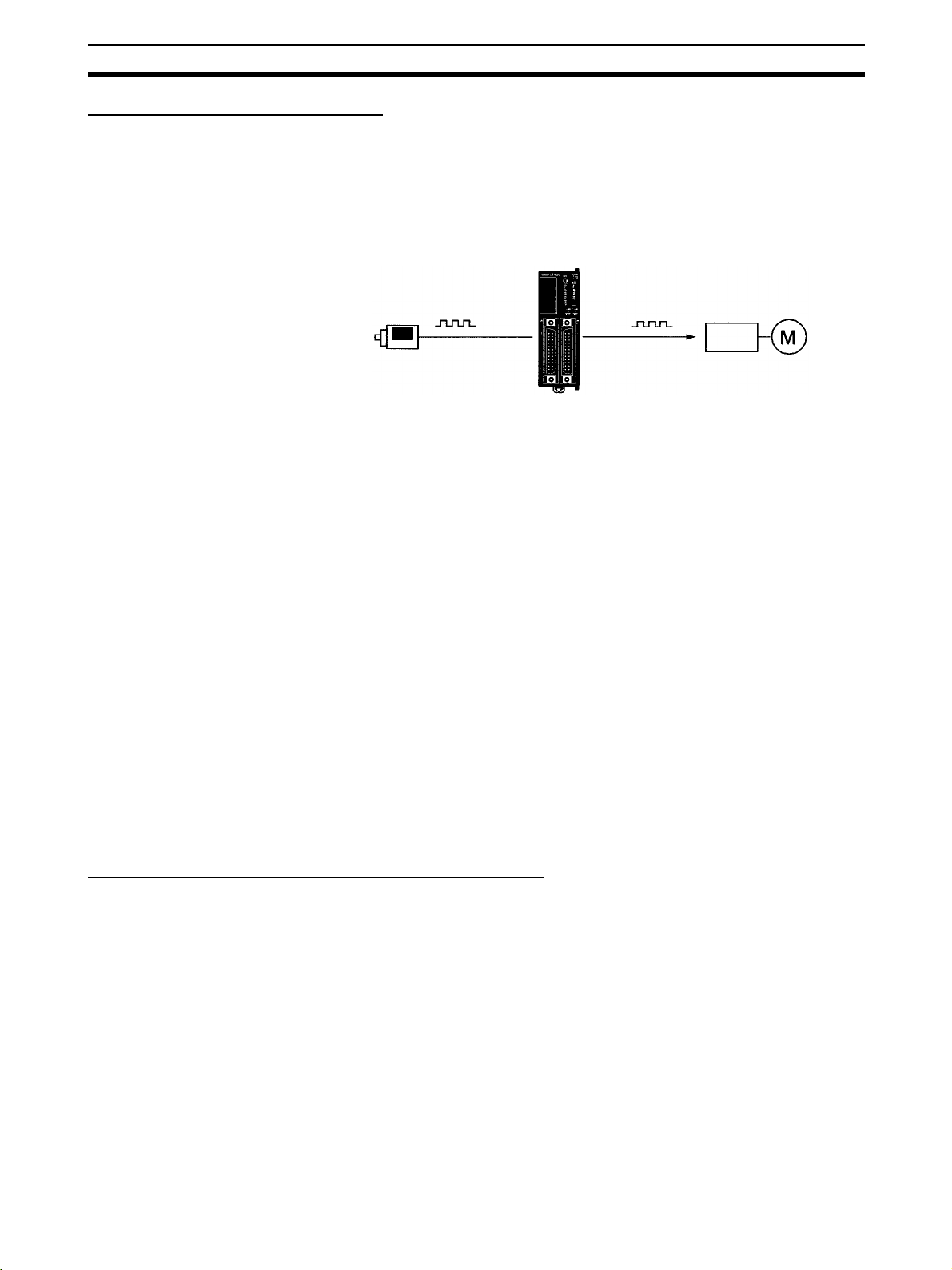
Built-in Motor Control Capability
Synchronized Pulse
Control
(Transistor Outputs Only)
Synchronized pulse control provides an easy way to synchronize the operation of a peripheral piece of equipment with the main equipment. The output
pulse frequency can be controlled as some multiple of the input pulse frequency, allowing the speed of a peripheral piece of equipment (such as a supply conveyor) to be synchronized with the speed of the main piece of
equipment.
CPM2C
High-speed Counters and
Interrupts
Easy Position Control with
Pulse Outputs
(Transistor Outputs Only)
Encoder
Pulses are out
ut as a fixed multiple of the input fre
Motor driver
uency.
Motor
The CPM2C has a two kinds of high-speed counter inputs. The high-speed
counter input has a response frequency of 5 or 20 kHz and the interrupt inputs
(in counter mode) have a response frequency of 2 kHz.
The single high-speed counter can be used in any one of the four input
modes: differential phase mode (5 kHz), pulse plus direction input mode
(20 kHz), up/down pulse mode (20 kHz), or increment mode (20 kHz). Interrupts can be triggered when the count matches a set value or falls within a
specified range.
The interrupt inputs (counter mode) can be used for incrementing counters or
decrementing counters (2 kHz) and trigger an interrupt (executing the interrupt program) when the count matches the target value. Four interrupt inputs
can be used in the 20- and 32-point CPU Units and two interrupt inputs can be
used in the 10-point CPU Units.
CPM2C PCs with transistor outputs have two outputs that can produce 10 Hz
to 10 kHz pulses (single-phase outputs).
When used as single-phase pulse outputs, there can be two outputs with a
frequency range of 10 Hz to 10 kHz with a fixed duty ratio or 0.1 to 999.9 Hz
with a variable duty ratio (0 to 100% duty ratio).
When used as pulse plus direction or up/down pulse outputs, there can be
just one output with a frequency range of 10 Hz to 10 kHz.
High-speed Input Capabilities for Machine Control
High-speed Interrupt Input
Function
Quick-response Input
Function
Stabilizing Input Filter
Function
The 20-point and 32-point CPU Units have 4 inputs that can be used as interrupt inputs and the 10-point CPU Units have 2 inputs that can be used as
interrupt inputs. These inputs are shared with quick-response inputs and interrupt inputs in counter mode and have a minimum input signal width of 50
and response time of 0.3 ms. When an interrupt input goes ON, the main program is stopped and the interrupt program is executed.
Regardless of the cycle time, the 20-point and 32-point CPU Units have 4
inputs that can be used as quick-response inputs and the 10-point CPU Units
have 2 inputs that can be used as quick-response inputs. These inputs are
shared with interrupt inputs and interrupt inputs in counter mode; they can
reliably read input signals with a signal width as short as 50
The input time constant for all inputs can be set to 1 ms, 2 ms, 3 ms, 5 ms,
10 ms, 20 ms, 40 ms, or 80 ms. The effects of chattering and external noise
can be reduced by increasing the input time constant.
µs
µs.
3
Page 27

CPM2C Features and Functions Section 1-1
Other Functions
Interval Timer Interrupts The interval timer can be set between 0.5 and 319,968 ms and can be set to
generate just one interrupt (one-shot mode) or periodic interrupts (scheduled
interrupt mode).
Calendar/Clock In CPU Units with a built-in clock, the clock (accuracy within 1 minute/month)
can be read from the program to show the current year, month, day, day of the
week, and time. The clock can be set from a Programming Device (such as a
Programming Console) or the time can be adjusted by rounding up or down to
the nearest minute.
Long-term Timer TIML(
−−) is a long-term timer that accommodates set values up to 99,990
seconds (27 hours, 46 minutes, 30 seconds). When combined with the SECONDS TO HOURS conversion instruction (HMS(
vides an easy way to control equipment scheduling.
−−)), the long-term timer pro-
Greater Data Handling Capability with Expansion Units
Analog I/O Supported Up to 4 Analog I/O Units can be mounted to the CPM2C. For each Analog I/O
Unit mounted to the Unit, 2 analog input points and 1 analog output point are
available. By mounting 3 (see note) Analog I/O Units, a maximum of 8 analog
input points and 4 analog output points can be made available. (By using a
combination of the PID(
tional control is possible.)
• The ranges supported for analog input signals are 0 to 5 V, 0 to 10 V, –10
to 10 V, 0 to 20 mA, and 4 to 20 mA, and the resolution is 1/6000 (full
scale). The average processing function and power interruption detection
function can be used.
• The ranges supported for analog output signals are 1 to 5 V, 0 to 10 V,
–10 to 10 V, 0 to 20 mA, and 4 to 20 mA, and the resolution is 1/6000 (full
scale).
Note When using the CPM2C-PA201, there is a limit to the number of CPM2C-
MAD11 Units that can be connected. This limit ensures that the power consumption of the CPU Unit, Expansion Units, and Expansion I/O Units does not
exceed the total power capacity of the service power supply from the Power
Supply Unit (24 V x 600 mA = 14.4 W).
−−) instruction and PWM(−−) instruction, time propor-
• CPU Unit with 4-W power consumption: Connect no more than two
CPM2C-MAD11 Units
• CPU Unit with 3-W power consumption: Connect no more than three
CPM2C-MAD11 Units
Temperature Sensor Units Up to 4 Temperature Sensor Units can be mounted to the CPM2C. There are
2 models of Temperature Sensor Unit: One for input from a thermocouple sensor and one for input from a platinum resistance thermometer sensor. There
are 2 input points on each Temperature Sensor Unit.
CompoBus/S I/O Link
Units
• Thermocouple inputs (and measurement ranges): K (–200 to 1,300
0.0 to 500.0
• Platinum resistance thermometer inputs (and measurement ranges):
Pt100 (–200.0 to 650.0
The CPM2C can be used as a CompoBus/S Slave (with 8 built-in inputs and 8
built-in outputs) by connecting a CompoBus/S I/O Link Unit. Up to
5 CompoBus/S I/O Link Units can be connected to the CPM2C. In addition to
the conventional “PC + Remote I/O” type of distributed I/O control, “PC + miniature PC” distributed CPU control is now possible. This means increased
°C), J (–100 to 850°C, 0.0 to 400.0°C).
°C), JPt100 (–200.0 to 650.0°C).
°C,
4
Page 28
CPM2C Features and Functions Section 1-1
(Up
)
modularization, allowing greater standardization of design, improved suitability to special needs, and easier replacement of malfunctioning Units.
Simple Communications
Unit
A Simple Communications Unit can be added to achieve data transfers with
general-purpose communications components without preparing communications programs in the PC. Up to 32 communications components can be connected, including a combination of communications components supporting
the CompoWay/F protocol along with temperature controllers and Digital
Panel Meters supporting the SYSWAY protocol.
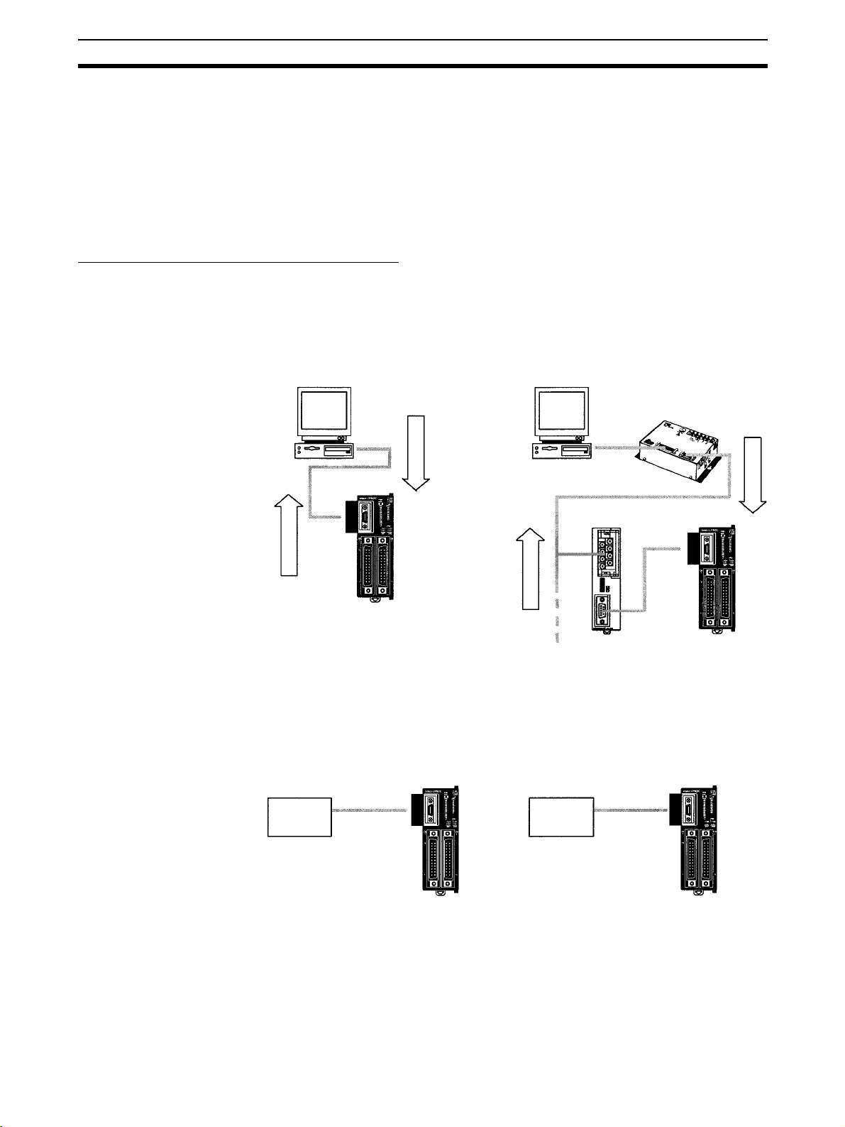
Complete Communications Capabilities
Host Link A Host Link connection can be made through the PC’s communications port
used as a RS-232C or peripheral port. A personal computer or Programmable
Terminal connected in Host Link mode can be used for operations such as
reading/writing data in the PC’s I/O memory or reading/changing the PC’s
operating mode.
1:1 Host Link Communications
Commands
CPM2C
1:N Host Link Communications
B500-AL004
Link Adapter
NT-AL001
Commands
CPM2C
No-protocol
Communications
High-speed 1:1 NT Link
Communications
Responses
Responses
to 32 PCs can be connected.
The TXD(48) and RXD(47) instructions can be used in no-protocol mode to
exchange data with standard serial devices. For example, data can be
received from a bar code reader or transmitted to a serial printer. The serial
devices can be connected to the communications port as a RS-232C or
peripheral port.
Inputting data from
a bar code reader
Bar code
reader
CPM2C CPM2C
Outputting data to
a serial printer
Serial
printer
In a 1:1 NT Link, an OMRON Programmable Terminal (PT) can be connected
directly to the CPM2C. The PT must be connected to the communications
port as an RS-232C port (not as a peripheral port).
5
Page 29

CPM2C Features and Functions Section 1-1
OMRON PT
CPM2C
One-to-one PC Link A CPM2C can be linked directly to another CPM2C, CQM1, CPM1, CPM1A,
CPM2A, SRM1(-V2), or a C200HS or C200HX/HG/HE PC. The 1:1 PC Link
allows automatic data link connections. The PC must be connected to the
communications port as an RS-232C port (not as a peripheral port).
CPM2C CPM2C
Expansion Memory Unit The CPM1-EMU01-V1 Expansion Memory Unit is a program loader for small-
size or micro PCs. Using the CPM1-EMU01-V1, simple on-site transfer of
user programs and data memory is possible with PCs.
CPM2C
Expansion Memory Unit
EEPROM
Indicator
UPLOAD+DM Button UPLOAD Button
CPM2C-CN111
CS1W-CN114
CPM2C
CPM2C-CIF01-V1
6
Page 30

CPM2C Features and Functions Section 1-1
1-1-2 Overview of CPM2C Functions
Main function Variations/Details
Interrupts Interrupt inputs
High-speed counters High-speed counter
Pulse outputs 2 outputs:
Synchronized pulse control 1 point, see notes 1 and 2.
Quick-response input 2 inputs in CPU Units with 10 I/O points, 4 inputs in CPU Units with 20/32 I/O points
Input time constant Determines the input time constant for all inputs. (Settings: 1, 2, 3, 5, 10, 20, 40, or 80 ms)
Calendar/Clock Shows the current year, month, day of the week, day of the month, hour, minute, and sec-
Expansion Unit functions Analog I/O functions using CPM2C-MAD11 Analog I/O Unit
Simple communications Simple communications functions using the CPM2C-CIF21 Simple Communications Unit
2 inputs in CPU Units with 10 I/O points, 4 inputs in CPU Units with 20/32 I/O points
Response time: 0.3 ms
Interval timer interrupts
1 input
Set value: 0.5 to 319,968 ms
Precision: 0.1 ms
1 input, see note 1.
Differential phase mode (5 kHz)
Pulse plus direction input mode (20 kHz)
Up/down input mode (20 kHz)
Increment mode (20 kHz)
Interrupt inputs (counter mode)
2 inputs in CPU Units with 10 I/O points,
4 inputs in CPU Units with 20/32 I/O points
Incrementing counter (2 kHz)
Decrementing counter (2 kHz)
Single-phase pulse output without acceleration/deceleration (See note 2.)
10 Hz to 10 kHz
2 outputs:
Variable duty ratio pulse output (See note 2.)
0.1 to 999.9 Hz, duty ratio 0% to 100%
1 output:
Pulse output with trapezoidal acceleration/deceleration (See note 2.)
Pulse plus direction output, up/down pulse output, 10 Hz to 10 kHz
Input frequency range: 10 to 500 Hz, 20 Hz to 1 kHz, or 300 Hz to 20 kHz
Output frequency range: 10 Hz to 10 kHz
Minimum input signal width: 50 µs
ond.
Two analog inputs: Input range of 0 to 5 V, 1 to 5 V, 0 to 10 V, –10 to 10 V, 0 to 20 mA, or
4 to 20 mA
One analog output: Output range of 1 to 5 V, 0 to 10 V, –10 to 10 V, 0 to 20 mA, or 4 to
20 mA
Temperature sensing functions using CPM2C-TS001/101 Temperature Sensor Unit
Thermocouple input (measurement range):K (–200 to 1,300°C)
K (0.0 to 500.0°C)
J (–100 to 850°C)
J (0.0 to 400.0°C)
Platinum resistance thermometer (measurement range):Pt100 (–200.0 to 650.0°C)
JPt100 (–200.0 to 650.0°C)
CompoBus/S Slave functions using CPM2C-SRT21 CompoBus/S I/O Link Unit
Data exchange with the Master Unit via 8 inputs and 8 outputs.
Up to 32 communications components can be connected, including communications components supporting the CompoWay/F protocol and temperature controllers and Digital
Panel Meters supporting the SYSWAY protocol.
Either RS-422 or RS-485 connections.
Scheduled interrupts
One-shot interrupt
No interrupt
Count-check interrupt
(An interrupt can be generated when the
count equals the set value or the count
lies within a preset range.)
No interrupt
Count-up interrupt
7
Page 31

CPM2C Features and Functions Section 1-1
Note 1. This input is shared by the high-speed counter and synchronized pulse
control functions.
2. This output is shared by the pulse output and synchronized pulse control
functions. These functions can be used with transistor outputs only.
8
Page 32

System Configurations Section 1-2
1-2 System Configurations
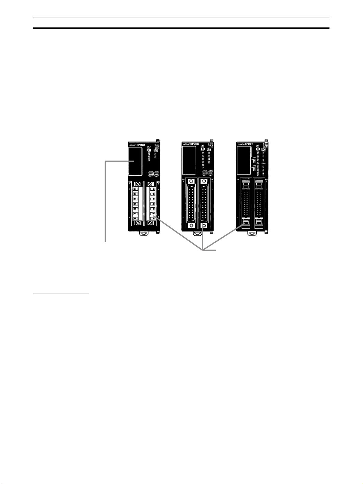
1-2-1 CPU Units
CPU Units with 10 I/O Points
CPU Unit with
Transistor Outputs
via MIL Connector
10 I/O points
(6 inputs,
4 outputs)
CPU Unit with
Relay Outputs via
Terminal Block
CPU Unit Inputs Outputs Clock Model
I/O terminal block 6 inputs (24 VDC) 4 relay outputs No CPM2C-10CDR-D*
I/O
connector
Fujitsucompatible
connector
MIL
connector
6 inputs (24 VDC) 4 transistor outputs
6 inputs (24 VDC) 4 transistor outputs
CPU Unit with
Transistor Outputs via
Fujitsu-compatible
Connector
(sinking)
4 transistor outputs
(sourcing)
(sinking)
4 transistor outputs
(sourcing)
Yes CPM2C-10C1DR-D*
No CPM2C-10CDTC-D*
Yes CPM2C-10C1DTC-D*
No CPM2C-10CDT1C-D*
Yes CPM2C-10C1DT1C-D*
No CPM2C-10CDTM-D
Yes CPM2C-10C1DTM-D
No CPM2C-10CDT1M-D
Yes CPM2C-10C1DT1M-D
Note The function of the SW2 is different from that described in this manual for all
CPU Units with 20 I/O Points
Relay Outputs via
CPU Unit Inputs Outputs Clock Model
20 I/O points
(12 inputs,
8 outputs)
I/O terminal block 12 inputs (24 VDC) 8 relay outputs No CPM2C-20CDR-D
I/O
connector
Fujitsucompatible
connector
MIL
connector
Units marked with an asterisk in the above table with lot numbers of 3180O
(August 2000) or earlier. Refer to
CPU Unit with
Terminal Block
12 inputs (24 VDC) 8 transistor outputs
12 inputs (24 VDC) 8 transistor outputs
CPU Unit with
Transistor Outputs via
Fujitsu-compatible
1-7 Changes in SW2 for details.
Connector
Yes CPM2C-20C1DR-D
(sinking)
8 transistor outputs
(sourcing)
(sinking)
8 transistor outputs
(sourcing)
No CPM2C-20CDTC-D*
Yes CPM2C-20C1DTC-D*
No CPM2C-20CDT1C-D*
Yes CPM2C-20C1DT1C-D*
No CPM2C-20CDTM-D
Yes CPM2C-20C1DTM-D
No CPM2C-20CDT1M-D
Yes CPM2C-20C1DT1M-D
CPU Unit with
Transistor Outputs
via MIL Connector
9
Page 33

System Configurations Section 1-2
Note The function of the SW2 is different from that described in this manual for all
Units marked with an asterisk in the above table with lot numbers of 3180O
(August 2000) or earlier. Refer to
CPU Units with 32 I/O Points
1-7 Changes in SW2 for details.
CPU Unit Inputs Outputs Clock Model
32 I/O points
(16 inputs,
16 outputs)
I/O
connector
Fujitsucompatible
connector
MIL
connector
1-2-2 Power Supply Unit
CPU Unit with
Transistor Outputs via
Fujitsu-compatible
Connector
16 inputs (24 VDC) 16 transistor out-
puts (sinking)
16 transistor out-
puts (sourcing)
16 inputs (24 VDC) 16 transistor out-
puts (sinking)
16 transistor out-
puts (sourcing)
AC Power Supply Unit
Transistor Outputs
via MIL Connector
CPU Unit with
No CPM2C-32CDTC-D
No CPM2C-32CDT1C-D
No CPM2C-32CDTM-D
No CPM2C-32CDT1M-D
Name Ratings Model
AC Power Supply Unit 100 to 240 VAC input
24 VDC, 600 mA output
CPM2C-PA201
1-2-3 CPU Unit, Expansion Units, and Expansion I/O Units
A series of up to 5 Expansion I/O Units or Expansion Units can be connected
to the expansion I/O connector on the CPU Unit.
10
Page 34

System Configurations Section 1-2
(
)
(
)
There are five types of Units available: Expansion I/O Units, an Analog I/O
Unit, Temperature Sensor Units, a CompoBus/S I/O Link Unit, and a Simple
Communications Unit.
Expansion I/O Units
CPU Unit
Expansion I/O Connector
(with cover)
Expansion I/O Unit
or Expansion Unit
Expansion I/O Connector
(output side, no cover)
Expansion I/O Connector
(input side)
A PC with 192 I/O points (the maximum) can be assembled by connecting five
Expansion I/O Units to a CPU Unit with 32 I/O points.
CPM2C-32CDTC-D
16 inputs, 16 outputs
1 Unit + 5 Units = 96 inputs, 96 outputs
CPM2C-32EDTC
16 inputs, 16 outputs
Note Be sure that the power supply requirements of the CPU Unit, Expansion
Units, and Expansion I/O Units do not exceed the available capacity. Only
three Expansion I/O Units or Expansion Units can be connected when the NTAL001 Adapter is connected to the communications port (as a RS-232C port).
Units with Relay Outputs (via Terminal Block)
10 I/O Points 8 Output Points20 I/O Points
Unit I/O Inputs Outputs Model
10 I/O points 6 inputs (24 VDC) 4 relay outputs CPM2C-10EDR
20 I/O points 12 inputs (24 VDC) 8 relay outputs CPM2C-20EDR
8 output points --- 8 relay outputs CPM2C-8ER
11
Page 35

System Configurations Section 1-2
Units with Transistor Outputs via Fujitsu-compatible Connector
8 Output Points 16 Input Points 16 Output Points8 Input Points32 I/O Points24 I/O Points
Unit I/O Inputs Outputs Model
24 I/O points 16 inputs (24 VDC) 8 transistor outputs (sinking) CPM2C-24EDTC
8 transistor outputs (sourcing) CPM2C-24EDT1C
32 I/O points 16 inputs (24 VDC) 16 transistor outputs (sinking) CPM2C-32EDTC
16 transistor outputs (sourcing) CPM2C-32EDT1C
8 input points 8 inputs (24 VDC) --- CPM2C-8EDC
16 input points 16 inputs (24 VDC) --- CPM2C-16EDC
8 output points --- 8 transistor outputs (sinking) CPM2C-8ETC
--- 8 transistor outputs (sourcing) CPM2C-8ET1C
16 output points --- 16 transistor outputs (sinking) CPM2C-16ETC
--- 16 transistor outputs (sourcing) CPM2C-16ET1C
Units with Transistor Outputs via MIL Connector
8 Input or
8 Output Points32 I/O Points24 I/O Points
Unit I/O Inputs Outputs Model
24 I/O points 16 inputs (24 VDC) 8 transistor outputs (sinking) CPM2C-24EDTM
8 transistor outputs (sourcing) CPM2C-24EDT1M
32 I/O points 16 inputs (24 VDC) 16 transistor outputs (sinking) CPM2C-32EDTM
16 transistor outputs (sourcing) CPM2C-32EDT1M
8 input points 8 inputs (24 VDC) --- CPM2C-8EDM
16 input points 16 inputs (24 VDC) --- CPM2C-16EDM
8 output points --- 8 transistor outputs (sinking) CPM2C-8ETM
--- 8 transistor outputs (sourcing) CPM2C-8ET1M
16 output points --- 16 transistor outputs (sinking) CPM2C-16ETM
--- 16 transistor outputs (sourcing) CPM2C-16ET1M
16 Input or
16 Output Points
12
Page 36

System Configurations Section 1-2
t
Expansion Units
CPM2C-MAD11
Analog I/O Unit
CPM2C-TS001
Temperature Sensor Unit
CPM2C-SRT21
CompoBus/S I/O Link Unit
CPM2C-CIF21
Simple Communications Unit
Unit Max. number
Analog I/O Unit 2 analog inputs
1 analog output
Temperature Sensor Unit
CompoBus/S I/O
Link Unit
Simple Communications Unit
(See notes 1 and 2.)
2 thermocouple
inputs
2 platinum resistance thermometer
inputs
8 input points and 8
output points for
the built-in outputs
and inputs of the
Master Unit
Note 1. Do not use the CPM2C-CIF21 Simple Communications Unit with an Units
Adapter Units
of Units
4 2 points, 2 words
4 2 points, 2 words
5 8 points, 1 word
--- CPM2C-CIF21
Inputs Outputs Model
1 point, 1 word allo-
allocated
allocated
2 points, 2 words
allocated
allocated
(Inputs from the
Master)
cated
--- CPM2C-TS001
--- CPM2C-TS101
8 points, 1 word
allocated
(Outputs to the
Master)
CPM2C-MAD11
CPM2C-SRT21
other than CPM2C Units.
2. The CPM2C-CIF21 Simple Communications Unit is due for release in December 2000.
Peripheral/RS-232C Adapter Unit RS-422/232C Adapter Uni
Unit Conversion Model
Peripheral/RS-232C Adapter Unit CPU Unit’s communications port →
RS-422/RS-232C Adapter Unit CPU Unit’s communications port →
Peripheral port + RS-232C port
RS422 port + RS-232C port
Note 1. The CPM2C-CIF01-V1 cannot be used with any PC model other than the
CPM2C. A CPM2C-CIF11 or another CPM2C-CIF01-V1 cannot be connected onto a CPM2C-CIF01-V1.
CPM2C-CIF01-V1
CPM2C-CIF11
13
Page 37

Structure and Operation Section 1-3
2. Although a CPM2C-CN111 can be connected to a CPM2C-CIF01-V1, it is
not possible to use the peripheral port and the RS-232C port on the
CPM2C-CN111 simultaneously. If an attempt is made to use both ports simultaneously, communications will not be performed properly and incorrect operation may result.
1-3 Structure and Operation
1-3-1 CPU Unit Structure
The following diagram shows the internal structure of the CPU Unit.
I/O memory
External
input
devices
Input circuits
Communications
port
Program
Settings
Settings
Communications
switch
PC Setup
Output circuits
Settings
External
output
devices
I/O Memory The program reads and writes data in this memory area during execution.
Part of the I/O memory contains the bits that reflect the status of the PC’s
inputs and outputs. Parts of the I/O memory are cleared when the power is
turned ON and other parts are retained.
Note Refer to Section 3 Memory Areas in the Programming Manual (W353) for
more details on I/O memory.
Program This is the program written by the user. The CPM2C executes the program
cyclically. (Refer to
1-3-5 Cyclic Operation and Interrupts for details.)
The program can be divided broadly into two parts: the “main program” that is
executed cyclically and the “interrupt programs” that are executed only when
the corresponding interrupt is generated.
PC Setup The PC Setup contains various startup and operating parameters. The PC
Setup parameters can be changed from a Programming Device only; they
cannot be changed from the program.
Some parameters are accessed only when PC’s power supply is turned ON
and others are accessed regularly while the power is ON. It will be necessary
to turn the power OFF and then ON again to enable a new setting if the
parameter is accessed only when the power is turned ON.
Note Refer to Section 1 PC Setup in the Programming Manual (W353) for more
details.
Communications Switch The Communications Switch controls the communications settings for the
peripheral port and the RS-232C port.
14
Page 38

Structure and Operation Section 1-3
1-3-2 Operating Modes
CPM2C CPU Units have 3 operating modes: PROGRAM, MONITOR, and
RUN.
PROGRAM Mode The program cannot be executed in PROGRAM mode. This mode is used to
perform the following operations in preparation for program execution.
• Changing initial/operating parameters such as those in the PC Setup
• Writing, transferring, or checking the program
• Checking wiring by force-setting and force-resetting I/O bits
!Caution The PC continues to refresh I/O bits even if the PC is in PROGRAM mode, so
devices connected to output points on the CPU Unit, Expansion Units, or
Expansion I/O Units may operate unexpectedly if the corresponding output bit
is turned ON by changing the contents of I/O memory.
MONITOR Mode The program is executed in MONITOR mode and the following operations can
be performed from a Programming Device. In general, MONITOR mode is
used to debug the program, test operation, and make adjustments.
• Online editing
• Monitoring I/O memory during operation
• Force-setting/force-resetting I/O bits, changing set values, and changing
present values during operation
RUN Mode The program is executed at normal speed in RUN mode. Operations such as
online editing, force-setting/force-resetting I/O bits, and changing set values/
present values cannot be performed in RUN mode, but the status of I/O bits
can be monitored.
1-3-3 Operating Mode at Startup
The operating mode of the CPM2C when the power is turned ON depends
upon the PC Setup settings and the Programming Console’s mode switch setting if a Programming Console is connected.
PC Setup setting Operating mode
Word Bits Setting Programming Device
connected
DM 6600 08 to 15 00 (Hex) Programming Console:
Mode set on Programming
Console mode switch
Other Programming Device:
PROGRAM mode
01 (Hex) Startup mode is the same as the operating mode before
power was interrupted.
02 (Hex) Startup mode is determined by bits 00 to 07.
00 to 07 00 (Hex) PROGRAM mode
01 (Hex) MONITOR mode
02 (Hex) RUN mode
Programming Device not
connected
RUN mode
Note 1. The default setting for DM 6600, bits 06 to 15 is 00 Hex, i.e., to start with
the mode set on the Programming Console’s mode switch. If a Programming Device is not connected to the peripheral connector on the CPU Unit,
the CPU Unit will start in RUN mode as soon as power is turned ON. Be
sure that adequate precautions are taken to ensure safety.
15
Page 39

Structure and Operation Section 1-3
2. The setting of SW2 will affect the startup operating mode for all Units with
lot numbers of 3180O (August 2000) or earlier. Refer to
SW2
for details.
1-7 Changes in
1-3-4 PC Operation at Startup
Time Required for
Initialization
Power OFF Operation
The time required for startup initialization depends on several factors, such as
the operating conditions (including power supply voltage, system configuration, and ambient temperature) and the program contents.
Minimum Power Supply Voltage
The PC will stop and all outputs will be turned OFF if the power supply voltage
falls below 85% of the rated value.
Momentary Power Interruption
A power interruption will not be detected and CPU Unit operation will continue
if the power interruption lasts less than 2 ms.
A power interruption may or may not be detected for power interruptions
somewhat longer than 2 ms.
When a power interruption is detected, the CPU Unit will stop operating and
all outputs will be turned OFF.
Automatic Reset
Operation will restart automatically when the power supply voltage is restored
to more than 85% of the rated voltage.
Timing Chart of Power OFF Operation
The power interruption detection time is the time required for a power interruption to be detected after the power supply voltage drops below 85% of the
rated value.
1,2,3... 1. Minimum power interruption detection time
Power interruptions that are shorter than 2 ms will not be detected.
16
Page 40

Structure and Operation Section 1-3
2. Undetermined additional time
Power interruptions only slightly longer than the minimum power interruption time may not be detected.
85% of rated voltage
Detection of
power interruption
Program execution
CPU reset signal
1. Minimum time 2. Additional
Executing
CPU Unit operation will
continue if voltage is
restored in this region.
time
Stopped
CPU Unit operation may
continue if voltage is
restored in this region.
Note If the power supply voltage fluctuates around 85% of the PC’s rated voltage,
PC operation may stop and restart repeatedly. When repeated stopping and
starting will cause problems with the controlled system, set up a protective circuit such as a circuit that shuts OFF the power supply to sensitive equipment
until the power supply voltage returns to the rated value.
17
Page 41

Structure and Operation Section 1-3
1-3-5 Cyclic Operation and Interrupts
Basic CPU Operation Initialization processing is performed when the power is turned ON. If there
are no initialization errors, the overseeing processes, program execution, I/O
refreshing, and communications port servicing are performed repeatedly
(cyclically).
• Check hardware.
Startup initialization
Overseeing
processes
• Check memory.
• Read data from flash memory (program,
read-only DM data, and PC Setup settings).
• Check for battery error.
• Preset the watch (maximum) cycle time.
• Check program memory.
• Refresh bits for expansion functions.
Program execution
Cycle time
PC cycle time
calculation
I/O refreshing
RS-232C port
servicing
• Execute the program.
(Refer to the Programming Manual (W353) for
details on cycle time and I/O response times.)
• Wait for minimum cycle time if a minimum
cycle time has been set in the PC Setup
(DM 6619).
• Calculate cycle time.
• Read input data from input bits.
• Write output data to output bits.
• Perform RS-232C port communications
processing. (Can be changed in DM 6616.)
18
Peripheral port
servicing
• Perform peripheral port communications
processing. (Can be changed in DM 6617.)
The cycle time can be read from a Programming Device.
AR 14 contains the maximum cycle time and AR 15 contains the present
cycle time in multiples of 0.1 ms.
Page 42

Structure and Operation Section 1-3
C
t
The cycle time will vary slightly depending on the processing being performed
in each cycle, so the calculated cycle time will not always match the actual
cycle time.
Program Execution in
Cyclic Operation
The following diagram shows the cyclic operation of the CPM2C when the
program is being executed normally.
Normally, the results of program execution are transferred to I/O memory just
after program execution (during I/O refreshing), but IORF(97) can be used to
refresh a specified range of I/O words during program execution. The specified range of I/O words will be refreshed when IORF(97) is executed.
The cycle time is the sum of the time required for program execution, I/O
refreshing, and communications port servicing.
A minimum cycle time (1 to 9,999 ms) can be set in the PC Setup (DM 6619).
When a minimum cycle time has been set, CPU operation is paused after program execution until the minimum cycle time is reached. CPU operation will
not be paused if the actual cycle time is longer than the minimum cycle time
set in DM 6619.
Note A fatal error will occur and PC operation will stop if a maximum cycle time has
been set in the PC Setup (DM 6618) and the actual cycle time exceeds that
setting.
The default settings for RS-232C and peripheral port servicing are 5% each of
the cycle time, but these settings can be changed (between 0% and 99%) in
the PC Setup. The RS-232C port’s setting is in DM 6616 and the peripheral
port’s setting is in DM 6617.
Refer to Section 7 PC Operations and Processing Time in the Programming
Manual (W353) for more details and precautions on the cycle time.
Overseeing processes
Main program
ycle
ime
If a minimum cycle time has been
set in DM 6619, CPU operation is
paused until the minimum cycle
time is reached.
I/O refreshing
RS-232C port servicing
Peripheral port servicing
The servicing time can be set
in DM 6616.
The servicing time can be set
in DM 6617.
19
Page 43

Structure and Operation Section 1-3
t
Interrupt Program
Execution
When an interrupt is generated during execution of the main program, main
program execution is interrupted immediately and the interrupt program is
executed. The following diagram shows the cyclic operation of the CPM2C
when an interrupt program is executed.
Normally, the results of interrupt program execution are transferred to I/O
memory just after program execution (during I/O refreshing), but IORF(97)
can be used to refresh a specified range of I/O words during execution of the
interrupt program. The specified range of I/O words will be refreshed when
IORF(97) is executed.
The normal cycle time is extended by the time required for execution of the
interrupt program.
Refer to Section 7 PC Operations and Processing Time in the Programming
Manual (W353) for more details and precautions on the cycle time.
Overseeing processes
Main program
Interrupt generated.
Interrupt program
Cycle
ime
I/O refreshing
RS-232C port servicing
Peripheral port servicing
!Caution Although IORF(97) can be used in interrupt subroutines, you must be careful
of the interval between IORF(97) executions. If IORF(97) is executed too frequently, a fatal system error may occur (FALS 9F), stopping operation. The
interval between executions of IORF(97) should be at least 1.3 ms + total execution time of the interrupt subroutine.
Immediate Refreshing IORF(97) can be executed in the program to refresh a specified range of I/O
words. The specified I/O words will be refreshed when IORF(97) is executed.
IORF(97) can be used to refresh I/O from the main program or the interrupt
program.
20
Page 44
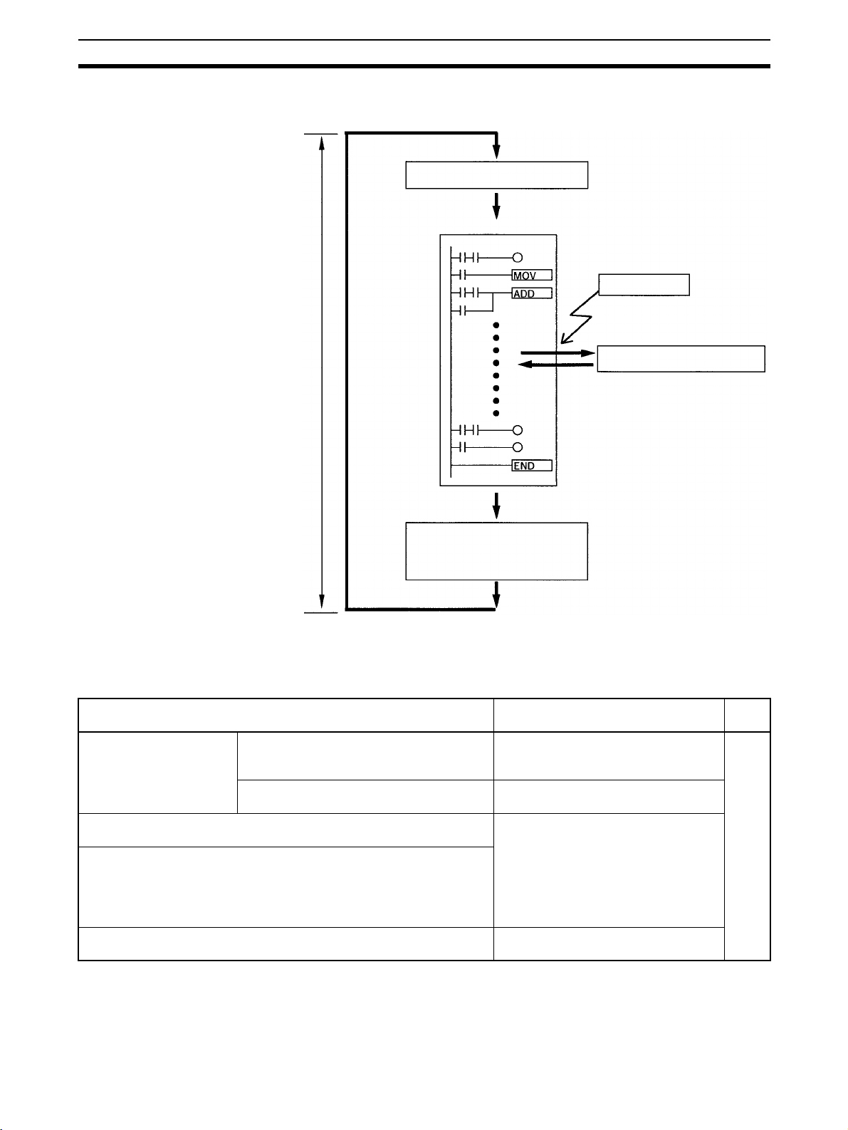
Functions Listed by Usage Section 1-4
When IORF(97) is used, the cycle time is extended by the time required to
refresh the specified I/O words.
Overseeing processes
Main program
IORF(97) executed.
Cycle
time
I/O refreshing
RS-232C port servicing
Peripheral port servicing
1-4 Functions Listed by Usage
Machine Control Functions
Usage Function Refer
Receive high-speed count
inputs
(For example, calculating
length or position with an
encoder).
Generate a pulse output based on a multiple of an input pulse to synchronize control of a peripheral process with the main process.
The multiple for the peripheral process (such as tool feed rate) can be
changed during operation by calculating the multiple from another input
value (such as an encoder) in the peripheral process.
This method can be used to change the process for different products or
models without stopping the equipment.
Reliably receive input pulses with an ON-time shorter than the cycle
time (such as inputs from a photomicrosensor).
Max. count frequency of 2 kHz
(single-phase)
Max. count frequency of 5 kHz (differential
phase) or 20 kHz (single-phase)
Immediate refreshing
I/O refreshing
Use interrupt input (counter mode) to
read the present value without interrupts.
Use high-speed counter to read the
present value without interrupts.
Pulse synchronization
Quick-response input function
to
W353
21
Page 45

Functions Listed by Usage Section 1-4
Usage Function Refer
Interrupt functions Execute a special process very quickly
when an input goes ON.
(For example, operating a cutter when an
interrupt input is received from a Proximity
Switch or Photoelectric Switch.)
Count input ON pulses and execute a special process very quickly when the count
reaches the preset value.
(For example, stopping the supply feed
when a preset number of workpieces have
passed through the system.)
Execute a special process at a preset count
value.
(For example, cutting material very precisely at a given length.)
Execute a special process when the count
is within a preset range.
(For example, sorting material very quickly
when it is within a given length range.)
Execute a special process when a timer
times out.
(For example, stopping a conveyor at very
precise time (independent of the cycle time)
after the workpiece is detected.)
Repeat a special process at regular intervals.
(For example, the speed of a sheet feeder
can be monitored by measuring the input
signal from an encoder at regular intervals
and calculating the speed.)
Perform simple positioning by outputting pulses to a motor driver that
accepts pulse-train inputs.
Receive an analog input and output an analog output. Analog I/O Unit
Receive temperature sensor input directly at the PC. Temperature Sensor Unit
Reduce required wiring, space, and PC load by controlling equipment
with a few low-capacity PCs dispersed near the equipment rather than a
single, large, centralized PC.
(Create a remote I/O link with a CompoBus/S Master and CompoBus/S
Slaves.)
Obtain data from SYSWAY-compatible temperature controllers, digital
panel meters, or CompoWay/F-compatible general-purpose communications components.
Interrupt input (interrupt input mode) W353
Interrupt input (counter mode)
High-speed counter interrupt generated when the count matches the set
value.
High-speed counter interrupt generated when the count is within the set
range.
Interval timer interrupt
(One-shot mode)
Interval timer interrupt
(Scheduled interrupt mode)
Pulse output function
(Connect the Analog I/O Unit to the
CPU Unit.)
(Connect the Temperature Sensor Unit
to the CPU Unit.)
CompoBus/S I/O Link Unit
(Connect the CompoBus/S I/O Link
Unit to the CPU Unit.)
Simple Communications Unit
(Connect the Simple Communications
Unit to the CPU Unit.)
to
page
221
22
Page 46

Comparison with the CPM1A and CPM2A Section 1-5
Basic Functions
Usage Function Refer
Set the cycle time to a fixed interval. Set a minimum (fixed) cycle time in the PC Setup. W353
Stop PC operation when the cycle time exceeds a max-
imum setting.
Keep all outputs ON when PC operation stops. Turn ON the IOM Hold Bit (SR 25212).
Retain the contents of I/O memory when starting opera-
tion.
Retain the contents of I/O memory when the PC is
turned ON.
Eliminate effects from chattering and external noise. Set a longer input time constant in the PC Setup.
Set a maximum (watch) cycle time in the PC Setup.
Turn ON the IOM Hold Bit (SR 25212).
Turn ON the IOM Hold Bit (SR 25212) and set the PC
Setup (DM 6601) so that the status of the IOM Hold Bit
is maintained at startup.
Maintenance Functions
Usage Function Refer
Record data with time-stamp. Clock/calendar function W353
Establish user-defined errors for desired input condi-
tions. (Fatal and non-fatal errors can be defined.)
Read the number of power interruptions. The number of power interruptions is stored in AR 23.
Set the startup operating mode. Set the startup operating mode in the PC Setup
FAL(06) defines non-fatal errors. (PC operation continues.)
FALS(07) defines fatal errors. (PC operation stops.)
(DM 6600).
to
to
Communications Functions
Usage Function Refer
Read/write I/O memory data and change the operating
mode from a host computer.
Connect to a serial device such as a bar code reader or
serial printer.
Make a high-speed connection with an OMRON Programmable Terminal.
Make a PC-PC data link connection with another
CPM2C, or a CPM1, CPM1A, CPM2A, SRM1, CQM1,
C200HS, or C200HX/HG/HE PC.
Connect a Programming Console. Connect the Programming Console to the peripheral
Connect a personal computer running SYSMAC Support Software (SSS) or SYSMAC-CPT Support Software.
Monitor equipment with a Programmable Terminal and
program the PC with a Programming Device.
Host Link communications (Set the communications
mode to Host Link in the PC Setup.)
No-protocol communications (Set the communications
mode to no-protocol in the PC Setup.)
1:1 NT Link (Set the communications mode to 1:1 NT
Link in the PC Setup.)
1:1 PC Link (Set the communications mode to 1:1 PC
Link in the PC Setup.)
port.
The computer can be connected to the peripheral port
or RS-232C port.
The RS-232C port and peripheral port can be used
simultaneously via the communications port.
1-5 Comparison with the CPM1A and CPM2A
to
W353
page
152
page
289
W353
page
289,
page
152
Item CPM2C CPM2A CPM1A
Instruction set Basic instructions 14 Same as CPM2C. Same as CPM2C.
Instruction execution times
Special instructions 105 instructions,
185 variations
Basic instructions LD: 0.64 µs Same as CPM2C. LD: 1.72 µs
Special instructions MOV(21): 7.8 µs Same as CPM2C. MOV(21): 16.3 µs
Same as CPM2C. 79 instructions,
139 variations
23
Page 47

Comparison with the CPM1A and CPM2A Section 1-5
Item CPM2C CPM2A CPM1A
Program capacity 4,096 words Same as CPM2C. 2,048 words
Maximum num-
ber of I/O points
Expansion Units
and Expansion
I/O Units
I/O memory Input bits IR 00000 to IR 00915 Same as CPM2C. Same as CPM2C.
Memory backup Program area, read-only DM
Interrupt inputs (interrupt input mode) 4 (20-/32-point CPU
Stand-alone CPU Unit 10, 20, or 32 points 30, 40, or 60 points 10, 20, 30, or
CPU Unit with Expansion I/O
Units
Maximum number of Units A maximum of 5 Units
Available models Expansion I/O Units,
Output bits IR 01000 to IR 01915 Same as CPM2C. Same as CPM2C.
Work bits 928 bits:
SR (Special Relay) area 448 bits:
TR (Temporary Relay) area 8 bits: TR0 to TR7 Same as CPM2C. Same as CPM2C.
HR (Holding Relay) area 320 bits:
AR (Auxiliary Relay) area 384 bits:
LR (Link Relay) area 256 bits:
Timer/Counter area 256 bits:
DM (Data
Memory) area
area (including PC Setup)
Read/write DM area, HR
area, AR area, and counters
Read/write
area
Read-only
area
PC Setup 56 words
170, 180, or 192 points
max.
can be connected to any
of the CPU Units.
Analog I/O Unit, Temperature Sensor Unit, CompoBus/S I/O Link Unit,
and Simple Communications Unit
IR 02000 to IR 04915,
IR 20000 to IR 22715
SR 22800 to SR 25515
HR 0000 to HR 1915
AR 0000 to AR 2315
LR 0000 to LR 1515
TIM/CNT 000 to
TIM/CNT 255
2,048 words
(DM 0000 to DM 2047)
456 words
(DM 6144 to DM 6599)
(DM 6600 to DM 6655)
Flash memory backup Same as CPM2C. Same as CPM2C.
CPU Unit with clock:
Internal battery backup
(2-year lifetime at 25°C,
replaceable)
CPU Unit without clock:
Capacitor backup
(10-day backup at 25°C)
or optional battery
backup (5 years at 25°C,
replaceable)
Unit),
2 (10-point CPU Unit)
90, 100, or 120 points
max.
A maximum of 3 Units
can be connected to
any of the CPU Units.
Same as CPM2C. Same as CPM2C.
Same as CPM2C. 512 bits:
Same as CPM2C. 384 bits:
Same as CPM2C. 256 bits:
Same as CPM2C. Same as CPM2C.
Same as CPM2C. 128 bits:
Same as CPM2C. 1,024 words
Same as CPM2C. Same as CPM2C.
Same as CPM2C. Same as CPM2C.
Internal battery
backup
(5-year lifetime at
25°C, replaceable)
44
40 points
90 or 100 points max.
A maximum of 3 Units
can be connected to
the 30-point and
40-point CPU Units.
IR 20000 to IR 23115
SR 23200 to
SR 25515
Same as CPM2C.
AR 0000 to AR 1515
TIM/CNT 0 to
TIM/CNT 127
(DM 0000 to
DM 1023)
Capacitor backup
(20-day backup at
25°C)
24
Page 48

Comparison with the CPM1A and CPM2A Section 1-5
Item CPM2C CPM2A CPM1A
Interrupt inputs
(counter mode)
Interval timer One-shot mode Yes Same as CPM2C. Same as CPM2C.
Quick-response
inputs
High-speed
counter
Pulse synchronization Supported. Not supported.
Counter mode Incrementing counter
Counter upper limit 2 kHz Same as CPM2C. 1 kHz
SR 244 to SR 247 Contains counter PV. Same as CPM2C. Contains counter
Method(s) to read counter PVRead SR 244 to SR 247.
Method to change counter PVExecute INI(61). Same as CPM2C. Not supported.
Scheduled interrupt mode Yes Same as CPM2C. Same as CPM2C.
Item CPM2C/CPM2A CPM1A
Setting the quick-response
function
INT(89) (Mask) Not supported (ignored) Supported.
INT(89) (Read mask) Reads mask status. Reads result of mask set-
INT(89) (Clear) Not supported (ignored) Supported.
Minimum pulse width 50 µs min. 200 µs min.
Count mode Differential-phase (up/down) mode
Max. counter frequency 5 kHz in differential-phase (up/down) mode
Counter PV range –8,388,608 to 8,388,607 in differential-
Check when registering target value match table
Method used to reference the
target value match interrupt
table
Reading range-comparison
results
Reading status Check AR 1108 (comparison in progress),
Decrementing counter
Execute PRV(62).
PC Setup PC Setup and INT(89)
Pulse plus direction mode
Up/down pulse mode
Increment mode
20 kHz in pulse plus direction mode, up/
down pulse mode, and increment mode
phase (up/down) mode, pulse plus direc-
tion mode, and up/down pulse mode
0 to 16,777,215 in increment mode
Same direction, same SV not possible Same direction, same SV
Comparison of all values in the table,
regardless of order of appearance in table
Check AR 1100 to AR 1107 or execute
PRV(62).
check AR 1109 (high-speed counter PV
overflow/underflow), or execute PRV(62).
Same as CPM2C. Decrementing
counter
PV–1.
Same as CPM2C. Read SR 244 to
SR 247.
(Counter PV – 1)
(Unmask interrupt input.)
ting.
Differential-phase
(up/down) mode
Increment mode
2.5 kHz in
differential-phase
(up/down) mode,
5 kHz in increment mode
–32,768 to 32,767 in
differential-phase
(up/down) mode
0 to 65,535 in increment
mode
possible
Comparison in order of
appearance in table
Check AR 1100 to
AR 1107.
---
25
Page 49

Comparison with the CPM1A and CPM2A Section 1-5
Item CPM2C/CPM2A CPM1A
Pulse output
control
Trapezoidal acceleration/
deceleration
PWM(−−) output Supported. Not supported.
Number of simultaneous
pulse outputs
Maximum frequency 10 kHz max. 2 kHz max.
Minimum frequency 10 Hz 20 Hz
Pulse output quantity –16,777,215 to 16,777,215 0 to 16,777,215
Direction control Supported. Not supported.
Positioning to absolute posi-
tions
Bit status while pulses are
being output
Reading PV Read SR 228 through SR 231 or execute
Resetting PV Supported. Not supported.
Status outputs Accelerating/decelerating
Supported with ACC(−−). The initial frequency can be set.
2 max. 1 max.
Supported. Not supported.
No effect Turned ON/OFF by pulse
PRV(62).
PV overflow/underflow
Pulse quantity set
Pulse output completed
Pulse output status
Not supported.
output
Not supported.
Pulse output status
Item CPM2C CPM2A CPM1A
Analog controls None 2 2
Clock function Internal or none Internal None
Words containing
time info.
Analog I/O Analog I/O Units can be
Temperature monitoring The CPU Unit can receive
CompoBus/S communications A CompoBus/S I/O Link Unit
Communications switch This switch determines
AR 17 to AR 21 AR 17 to AR 21 ---
connected.
temperature sensor input
from either thermocouples
or platinum resistance thermometers.
can be connected to provide
CompoBus/S Slave functions.
whether communications
are governed by the standard settings or PC Setup
settings. Also sets the Programming Device connection. (See note.)
Same as CPM2C. Same as CPM2C.
Same as CPM2C. Same as CPM2C.
Same as CPM2C. Same as CPM2C.
This switch determines
whether communications are governed by
the standard settings or
PC Setup settings.
None
Note The setting of SW2 will affect the operating mode for all Units with lot numbers
of 3180O (31 August 2000) or earlier. Refer to
1-7 Changes in SW2 for
details.
26
Page 50

Comparison with the CPM1A and CPM2A Section 1-5
Item CPM2C CPM2A CPM1A
Battery Battery CPU Unit with clock:
Battery replacement
Life expectancy/
backup time
Battery error detection
Communications
(in CPU Unit)
Input time constant Can be set to 1, 2, 3, 5, 10,
Peripheral port (via
communications
port)
RS-232C port (via
communications
port)
Internal lithium battery
backup
CPU Unit without clock:
Capacitor backup or
optional lithium battery
backup
Possible Possible ---
CPU Unit with clock: 2-year
lifetime at 25°C
CPU Unit without clock
(capacitor): 10-day backup
at 25°C
CPU Unit without clock (lithium battery): 5-year lifetime
at 25°C
Supported. Same as CPM2C. ---
Programming Console
(automatically detected)
(See note 2.)
Peripheral bus
(automatically detected)
Host Link (with Slave-initiated communications)
No-protocol
Peripheral bus (Set with
Communications Switch.)
Host Link
No-protocol
1:1 PC LInk
1:1 NT Link
20, 40, or 80 ms. (Default:
10 ms)
Lithium None (capacitor backup
5-year lifetime at 25°C 20-day backup at 25°C
Programming Console
(auto-detect)
Peripheral bus (autodetect)
Host Link (with Slaveinitiated communications)
No-protocol
Peripheral bus (autodetect)
Host Link
No-protocol
1:1 PC LInk
1:1 NT Link
Same as CPM2C. Can be set to 1, 2, 4, 8,
only)
Programming Console
(auto-detect)
Peripheral bus (autodetect)
Host Link
1:1 PC LInk
1:1 NT Link
None
16, 32, 64, or 128 ms.
(Default: 8 ms)
Note 1. An optional battery (CPM2C-BAT01) can be mounted to CPU Units without
clocks.
2. The setting of SW2 will affect the operating mode for all Units with lot numbers of 3180O (31 August 2000) or earlier. Refer to
1-7 Changes in SW2
for details.
27
Page 51

Comparison with the CPM1A and CPM2A Section 1-5
Differences in Instruction Sets
Instructions added to the
CPM2C
Mnemonic Name
TXD(48) TRANSMIT
RXD(47) RECEIVE
SCL(66) SCALING
SCL2(−−) SIGNED BINARY TO BCD SCALING
SCL3(−−) BCD TO SIGNED BINARY SCALING
SRCH(−−) DATA SEARCH
MAX(−−) FIND MAXIMUM
MIN(−−) FIND MINIMUM
SUM(−−) SUM CALCULATION
FCS(−−) FCS CALCULATE
HEX(−−) ASCII-TO-HEXADECIMAL
AVG(−−) AVERAGE VALUE
PWM(−−) PULSE WITH VARIABLE DUTY RATIO
PID(−−) PID CONTROL
ZCP(−−) AREA RANGE COMPARE
ZCPL(−−) DOUBLE AREA RANGE COMPARE
NEG(−−) 2’S COMPLEMENT
ACC(−−) ACCELERATION Control
STUP(−−) CHANGE RS-232C SETUP
SYNC(−−) SYNCHRONIZED PULSE CONTROL
BINL(58) DOUBLE BCD TO DOUBLE BINARY
BCDL(59) Double binary to double bcd
TMHH(−−) VERY HIGH-SPEED TIMER
TIML(−−) LONG TIMER
SEC(−−) HOURS-TO-SECONDS
HMS(−−) SECONDS-TO-HOURS
Instructions with Changed Specifications
Mnemonic Name CPM2C CPM1A
INI(61) MODE CONTROL Supports the interrupt input (counter mode) PV
PRV(62) HIGH-SPEED
COUNTER PV READ
CTBL(63) COMPARISON TABLE
LOAD
PULS(65) SET PULSES Supports absolute pulse specification, but the coordi-
INT(89) Interrupt control Supports a count-up interrupt for incrementing
change operation.
Supports the pulse output PV change operation.
Supports the pulse synchronization control stop
operation.
Supports the interrupt input (counter mode) PV read
operation.
Supports the pulse output PV read operation.
The count is compared with all of the target values in
the target value comparison table.
nate system must be set to absolute coordinates.
counters.
Does not support these
operations.
Does not support these
operations.
The count is compared
with each target value in
the order that they
appear in the target value
comparison table.
Does not support absolute pulse specification.
Does not support this
interrupt function.
28
Page 52

Comparison with the CPM1A and CPM2A Section 1-5
!Caution Before using a CPM1A program containing one or more of the instructions in
the table above, check the program to be sure that it will operate properly and
edit the program if necessary. The CPM2C may not operate properly if a
CPM1A program with these instructions is transferred and executed
unchanged.
Added Function Code
Allocations
The following three instructions are allocated function codes that were not
used in the CPM1A.
Instruction CPM2C CPM1A
RXD(47) RECEIVE Not allocated. (NOP(00))
TXD(48) TRANSMIT
SCL(66) SCALING
Differences in I/O Memory
SR Area Differences The following table shows differences in the SR area. (PV is the abbreviation
for present value.)
Function CPM2C CPM1A
Pulse output 0 PV SR 228 to SR 229 Not supPulse output 1 PV SR 230 to SR 231
Pulse output 0 PV Reset Bit SR 25204
Pulse output 1 PV Reset Bit SR 25205
RS-232C Port Reset Bit SR 25209
Battery Error Flag SR 25308
Changing RS-232C Port Setup Flag SR 25312
AR Area Differences The following table shows differences in the AR area.
Function CPM2C CPM1A
Clock/calendar data AR 17 to AR 21 Not supRS-232C Communications Error Code AR 0800 to AR 0803
RS-232C Error Flag AR 0804
RS-232C Transmission Enabled Flag AR 0805
RS-232C Reception Completed Flag AR 0806
RS-232C Reception Overflow Flag AR 0807
Peripheral Port Reception Completed Flag AR 0814
Peripheral Port Reception Overflow Flag AR 0815
RS-232C Reception Counter AR 09
High-speed Counter Comparison Flag AR 1108
High-speed Counter Overflow/Underflow Flag AR 1109
Pulse Output 0 Output Condition AR 1111
Pulse Output 0 PV Overflow/Underflow Flag AR 1112
Pulse Output 0 Pulse Quantity Set Flag AR 1113
Pulse Output 0 Output Completed Flag AR 1114
Pulse Output 1 PV Overflow/Underflow Flag AR 1212
Pulse Output 1 Pulse Quantity Set Flag AR 1213
Pulse Output 1 Output Completed Flag AR 1214
Pulse Output 1 Output Status AR 1215
Power OFF Counter AR 23 (See note.) AR 10
ported.
ported.
Note CPM1A programs that use AR 10 (the Power OFF Counter) cannot be used in
the CPM2C without editing the program. In the CPM2C, the Power OFF
Counter is in AR 23.
29
Page 53

Preparation for Operation Section 1-6
DM Area Differences The following table shows differences in the DM area other than the PC
Setup.
Function CPM2C CPM1A
Error Log Area DM 2000 to DM 2021 DM 1000 to DM 1021
Note CPM1A programs that use the Error Log Area cannot be used in the CPM2C
without editing the program to change the location of the Error Log Area.
The following table shows differences in the PC Setup.
Function CPM2C CPM1A
RS-232C Port Servicing Time Setting DM 6616 bits 00 to 07 Not supRS-232C Port Servicing Time Enable DM 6616 bits 08 to 15
Pulse Output 0 Coordinate System DM 6629 bits 00 to 03
Pulse Output 1 Coordinate System DM 6629 bits 04 to 07
RS-232C Communications Settings Selector DM 6645 bits 00 to 03
RS-232C Port CTS Control Settings DM 6645 bits 04 to 07
RS-232C Port Link Words for 1:1 PC Link DM 6645 bits 08 to 11
RS-232C Port Communications Mode DM 6645 bits 12 to 15
RS-232C Port Baud Rate DM 6646 bits 00 to 07
RS-232C Port Frame Format DM 6646 bits 08 to 15
RS-232C Port Transmission Delay DM 6647
RS-232C Port Host Link Node Number DM 6648 bits 00 to 07
RS-232C Port No-protocol Start Code Enable DM 6648 bits 08 to 11
RS-232C Port No-protocol End Code Enable DM 6648 bits 12 to 15
RS-232C Port No-protocol Start Code Setting DM 6649 bits 00 to 07
RS-232C Port No-protocol End Code Setting or
Number of Bytes Received
Peripheral Port No-protocol Start Code Enable DM 6653 bits 08 to 11
Peripheral Port No-protocol End Code Enable DM 6653 bits 12 to 15
Peripheral Port No-protocol Start Code Setting DM 6654 bits 00 to 07
Peripheral Port No-protocol End Code Setting or
Number of Bytes Received
Battery Error Detect Setting DM 6655 bits 12 to 15
DM 6649 bits 08 to 15
DM 6654 bits 08 to 15
ported
1-6 Preparation for Operation
Follow the steps listed below when setting up a CPM2C system.
1,2,3... 1. System Design
• Select a CPM2C CPU Unit, Expansion Units, and Expansion I/O Units
with the specifications required in the controlled system.
• Design external fail-safe circuits such as interlock circuits and limit circuits.
Refer to
2. Installation
Refer to
tails.
3. Wiring
30
2-1 Specifications and 3-1 Design Precautions for details.
• Connect the Expansion Units and Expansion I/O Units.
• Install the CPU Unit. (DIN-track installation)
3-3 Installing the CPM2C and 3-4 Wiring and Connections for de-
• Wire the power supply and I/O devices.
• Connect communications devices if necessary.
• Connect the Programming Console.
Page 54

Changes in SW2 Section 1-7
Refer to 3-4 Wiring and Connections, 4-1 Using a Programming Console,
for details.
4. Initial Settings
• Set the Communications Switch on the front of the CPU Unit, if necessary. (The switch must be set when a device other than the Programming Console is connected or the standard communications settings
are not used.)
• Connect the Programming Console, set the mode switch to PROGRAM mode, and turn ON the PC.
• Check the CPU Unit’s LED indicators and the Programming Console’s
display.
• Clear the PC’s memory. (All Clear)
• Make PC Setup settings.
Refer to
details.
Note The setting of SW2 will affect the operating mode for all Units with lot
5. Create Ladder Program
Refer to
Manual for details.
6. Write Ladder Program in PC
Refer to
port Software Operation Manuals and to the CPT User Manual for details.
7. Test Run
Refer to
3-3 Installing the CPM2C and 4-1-4 Preparation for Operation for
numbers of 3180O (August 2000) or earlier. Refer to
SW2
for details.
1-7 Changes in
• Create a ladder program to control the system.
SECTION 4 Using a Programming Console and the Programming
• Write the ladder program in the PC with the Programming Console or
transfer the program to the PC from the Support Software.
SECTION 4 Using a Programming Console, to the SYSMAC Sup-
• Check I/O wiring in PROGRAM mode.
• Check and debug program execution in MONITOR mode.
SECTION 5 Test Runs and Error Processing for details.
1-7 Changes in SW2
The connection of a Programming Console to the peripheral connector is
automatically detected for CPU Units with lot numbers of 0190O (1 September 2000) or later. This has resulted in a change to the operation of SW2 on
the front of the CPU Unit. Check the lot number to confirm the operation of
SW2 for any of the following model numbers before attempting operations.
CPU Units with Changed Specifications for SW2
I/O Units with Relay
Outputs and a
Terminal Block
10 I/O points CPM2C-10CDR-D
CPM2C-10C1DR-D
20 I/O points --- CPM2C-20CDTC-D
Units with Transistor Outputs and a
Sinking outputs Sourcing outputs
CPM2C-10CDTC-D
CPM2C-10C1DTC-D
CPM2C-20C1DTC-D
Connector
CPM2C-10CDT1C-D
CPM2C-10C1DT1C-D
CPM2C-20CDT1C-D
CPM2C-20C1DT1C-D
31
Page 55

Changes in SW2 Section 1-7
Interpreting Lot Numbers
Lot No. 31 8 0 O
Factor identification symbol
(Appears only on the side of the product.)
Year: Rightmost digit (2000 = 0)
Month: JAN to SEP = 1 to 9
OCT to DEC = X to Z
Day: 1 to 31
Operating Previous CPU Units
The following instructions apply to CPU Units with lot numbers of 3180O
(August 2000) or earlier.
The previous CPU Units do not detect a Programming Console connected to
the peripheral port, and SW2 of the DIP switch was used to set either “Programming Console” or “Other device.”
SW2 Setting
Communications
Switch
PRO
ON ON
SW1 SW2
SW1 SW2 Peripheral port RS-232C port
OFF OFF Programming Console connec-
tion
OFF ON Connection other than to Pro-
gramming Console according to
PC Setup in DM 6650 to
DM 6654.
ON OFF Programming Console connec-
tion
ON ON Connection other than to Pro-
gramming Console according to
standard settings.
According to PC Setup in
DM 6645 to DM 6649.
According to PC Setup in
DM 6645 to DM 6649.
According to standard settings.
According to standard settings.
The relationship between the PC Setup settings, the setting of SW2, and the
startup operating mode for previous CPU Units is shown in the following table.
PC Setup CPM2C Operating Mode
Address Bits Setting
DM6600 08 to 15 00 Hex According to communications switch SW2 and peripheral port device.
Peripheral device SW2 setting
OFF ON
Nothing connected PROGRAM mode RUN mode
Programming Con-
sole
Other PROGRAM mode
Note: Communications will not be possible between the CPM2C and the peripheral
device for these combinations.
01 Hex Mode used immediately before power interruption
02 Hex Mode specified in bits 00 to 07.
00 to 07 00 Hex PROGRAM mode
01 Hex MONITOR mode
02 Hex RUN mode
According to Programming
Console key switch.
(See note.)
PROGRAM mode
(See note.)
PROGRAM mode
32
Note 1. The default setting for DM 6600, bits 06 to 15 is 00 Hex, i.e., according to
the communications switch on the front panel. If SW2 is set for connecting
a device other than a Programming Console to the peripheral connector,
Page 56

Changes in SW2 Section 1-7
the CPU Unit will start in RUN mode as soon as power is turned ON. Be
sure that adequate precautions are taken to ensure safety.
2. If SW2 is for connecting a device other than a Programming Console to the
peripheral connector, the CPU Unit will start in RUN mode as soon as power is turned ON even if a device is connected to the RS-232C port. Be sure
that adequate precautions are taken to ensure safety.
Connections
IBM PC/AT
or compatib
XW2Z-200S-V
XW2Z-500S-V
le
CPM2C-CN111
CS1W-CN118
CPM2C-CIF01-V1
33
Page 57

Changes in SW2 Section 1-7
34
Page 58

SECTION 2
Unit Components and Specifications
This section describes the main components of the Units that go together to create a CPM2C PC and provides the technical
specifications of the Units.
2-1 Specifications . . . . . . . . . . . . . . . . . . . . . . . . . . . . . . . . . . . . . . . . . . . . . . . . . 36
2-1-1 General Specifications . . . . . . . . . . . . . . . . . . . . . . . . . . . . . . . . . . . 36
2-1-2 Characteristics. . . . . . . . . . . . . . . . . . . . . . . . . . . . . . . . . . . . . . . . . . 36
2-1-3 I/O Specifications . . . . . . . . . . . . . . . . . . . . . . . . . . . . . . . . . . . . . . . 38
2-1-4 AC Power Supply Unit Specifications . . . . . . . . . . . . . . . . . . . . . . . 46
2-2 Unit Components . . . . . . . . . . . . . . . . . . . . . . . . . . . . . . . . . . . . . . . . . . . . . . 47
2-2-1 CPU Unit Components . . . . . . . . . . . . . . . . . . . . . . . . . . . . . . . . . . . 47
2-2-2 Expansion I/O Units . . . . . . . . . . . . . . . . . . . . . . . . . . . . . . . . . . . . . 59
2-2-3 CPM2C-MAD11 Analog I/O Unit . . . . . . . . . . . . . . . . . . . . . . . . . . 69
2-2-4 CPM2C-TS001/TS101 Temperature Sensor Units. . . . . . . . . . . . . . 70
2-2-5 CPM2C-SRT21 CompoBus/S I/O Link Unit . . . . . . . . . . . . . . . . . . 72
2-2-6 CPM2C-CIF21 Simple Communications Unit. . . . . . . . . . . . . . . . . 73
2-2-7 CPM2C-CIF01-V1 Peripheral/RS-232C Adapter Unit . . . . . . . . . . 77
2-2-8 CPM2C-CIF11 RS-422/RS-232C Adapter Unit . . . . . . . . . . . . . . . 79
2-2-9 AC Power Supply Unit . . . . . . . . . . . . . . . . . . . . . . . . . . . . . . . . . . . 82
35
Page 59

Specifications Section 2-1
2-1 Specifications
2-1-1 General Specifications
Item CPU Units with 10/20 I/O points CPU Units with
Relay
outputs
Supply voltage 24 VDC
Operating voltage range 20.4 to 26.4 VDC
Power consumption CPM2C-10C@DR-@:4 W
Inrush current 25 A max.
Insulation resistance 20 MΩ min. (at 500 VDC) between insulated circuits
Dielectric strength 2,300 VAC for 1 min (between insulated circuits)
Noise immunity Conforms to IEC61000-4-4; 2 kV (power lines)
Vibration resistance
Shock resistance
Ambient temperature Operating: 0 to 55°C
Humidity 10% to 90% (with no condensation)
Atmosphere Must be free from corrosive gas
Power interrupt time 2 ms min.
CPM2C-10C@DT@C-D: 3 W
CPM2C-10C@DT@M-D: 3 W
CPM2C-20C@DR-@:4 W
CPM2C-20C@DT@C-D: 3 W
CPM2C-20C@DT@M-D: 3 W
CPM2C-32CDT@C-D: 3 W
CPM2C-32CDT@M-D: 3 W
Note The above values for CPU Unit power consump-
tion include the power consumption for Programming Consoles and Communications Adapter
Units (CIF@@).
10 to 57 Hz, 0.075-mm double amplitude, 57 to 150 Hz, acceleration: 9.8 m/s
directions for 80 minutes each (Time coefficient; 8 minutes × coefficient factor 10 = total time
80 minutes)
147 m/s
Storage: –20 to 75°C (except for the battery)
2
Transistor outputs
three times each in X, Y, and Z directions
32 I/O points
transistor
outputs
Expansion I/O Units and
Expansion Units
CPM2C-10EDR: 1 W
CPM2C-20EDR: 2 W
CPM2C-8ER: 2 W
CPM2C-24EDTC: 1 W
CPM2C-24EDT1C: 1 W
CPM2C-32EDTC: 1 W
CPM2C-32EDT1C: 1 W
CPM2C-8EDC: 1 W
CPM2C-16EDC: 1 W
CPM2C-8ETC: 1 W
CPM2C-8ET1C: 1 W
CPM2C-16ETC: 1 W
CPM2C-16ET1C: 1 W
CPM2C-24EDTM: 1 W
CPM2C-24EDT1M: 1 W
CPM2C-32EDTM: 1 W
CPM2C-32EDT1M: 1 W
CPM2C-8EDM: 1 W
CPM2C-16EDM: 1 W
CPM2C-8ETM: 1 W
CPM2C-8ET1M: 1 W
CPM2C-16ETM: 1 W
CPM2C-16ET1M: 1 W
CPM2C-MAD11: 3.5 W
CPM2C-TS001: 1.5 W
CPM2C-TS101: 1.5 W
CPM2C-SRT21: 1 W
CPM2C-CIF21: 1 W
2
in X, Y, and Z
2-1-2 Characteristics
Item CPU Unit Specification
10 I/O points
(relay/transistor outputs)
Control method Stored program method
I/O control method Cyclic scan with direct output (Immediate refreshing can be performed with IORF(97).)
36
20 I/O points
(relay/transistor outputs)
32 I/O points
(transistor outputs)
Page 60

Specifications Section 2-1
Item CPU Unit Specification
10 I/O points
(relay/transistor outputs)
Programming language Ladder diagram
Instruction length 1 step per instruction, 1 to 5 words per instruction
Instructions Basic instructions: 14
Execution time Basic instructions: 0.64 µs (LD instruction)
Program capacity 4,096 words
Max. I/O
capacity
Input bits IR 00000 to IR 00915 (Words not used for input bits can be used for work bits.)
Output bits IR 01000 to IR 01915 (Words not used for output bits can be used for work bits.)
Work bits 928 bits: IR 02000 to IR 04915 and IR 20000 to IR 22715
Special bits (SR area) 448 bits: SR 22800 to SR 25515
Temporary bits (TR area) 8 bits (TR0 to TR7)
Holding bits (HR area) 320 bits: HR 0000 to HR 1915 (Words HR 00 to HR 19)
Auxiliary bits (AR area) 384 bits: AR 0000 to AR 2315 (Words AR 00 to AR 23)
Link bits (LR area) 256 bits: LR 0000 to LR 1515 (Words LR 00 to LR 15)
Timers/Counters 256 timers/counters (TIM/CNT 000 to TIM/CNT 255)
Data memory Read/Write: 2,048 words (DM 0000 to DM 2047)*
Interrupt processing 2 interrupts 4 interrupts 4 interrupts
Interval timer interrupts 1 (Scheduled Interrupt Mode or Single Interrupt Mode)
High-speed counter One high-speed counter: 20 kHz single-phase or 5 kHz two-phase (linear count method)
Interrupt Inputs
(Counter mode)
Pulse output Two points with no acceleration/deceleration, 10 Hz to 10 kHz each, and no direction control.
Synchronized pulse control One point:
Quick-response inputs 2 inputs 4 inputs 4 inputs
Input time constant
(ON response time =
OFF response time)
CPU Unit only 10 points 20 points 32 points
With Expansion
I/O Units and
Expansion Units
Special instructions: 105 instructions, 185 variations
Special instructions: 7.8 µs (MOV instruction)
170 points max. 180 points max. 192 points max.
1-ms timers: TMHH(−−)
10-ms timers: TIMH(15)
100-ms timers: TIM
1-s/10-s timers: TIML(−−)
Decrementing counters: CNT
Reversible counters: CNTR(12)
Read-only: 456 words (DM 6144 to DM 6599)
PC Setup: 56 words (DM 6600 to DM 6655)
*The Error Log is contained in DM 2000 to DM 2021.
Shared by the external interrupt inputs (counter mode) and the quick-response inputs.
Counter interrupt: 1 (set value comparison or set-value range comparison)
2 inputs 4 inputs 4 inputs
Shared by the external interrupt inputs and the quick-response inputs.
One point with trapezoid acceleration/deceleration, 10 Hz to 10 kHz, and direction control.
Two points with variable duty-ratio outputs.
(Pulse outputs can be used with transistor outputs only, they cannot be used with relay outputs.)
A pulse output can be created by combining the high-speed counter with pulse outputs and
multiplying the frequency of the input pulses from the high-speed counter by a fixed factor.
(This output is possible with transistor outputs only, it cannot be used with relay outputs.)
Shared by the external interrupt inputs and the interrupt inputs (counter mode).
Min. input pulse width: 50 µs max.
Can be set for all input points.
(1 ms, 2 ms, 3 ms, 5 ms, 10 ms, 20 ms, 40 ms, or 80 ms)
20 I/O points
(relay/transistor outputs)
32 I/O points
(transistor outputs)
37
Page 61

Specifications Section 2-1
Item CPU Unit Specification
10 I/O points
(relay/transistor outputs)
Clock function Shows the year, month, day of the week, day, hour, minute,
Communications functions A CPM2C-CN111, CS1W-CN114, or CS1W-CN118 Connecting Cable is required to connect
Functions provided by
Expansion Units
Memory protection
(See notes 1 and 2.)
Memory backup
(See notes 1 and 2.)
Self-diagnostic functions CPU Unit failure (watchdog timer), I/O bus error, battery error, and memory failure
Program checks No END instruction, programming errors (checked when operation is started)
and second. (Battery backup) The CPU Units with “C1” in the
model number have a built-in clock.
to the CPM2C’s communications port. The communications port can be used as both a
peripheral and RS-232C port.
Peripheral port:
Supports Host Link, peripheral bus, no-protocol, or Programming Console connections.
RS-232C port:
Supports Host Link, no-protocol, 1:1 Slave Unit Link, 1:1 Master Unit Link, or 1:1 NT Link
connections.
Analog I/O Unit: Provides 2 analog inputs and 1 analog output.
Temperature Sensor Unit: Provides up to 8 thermocouple or platinum resistance thermome-
ter inputs.
CompoBus/S I/O Link Unit: Provides 8 inputs and 8 outputs as a CompoBus/S Slave.
HR area, AR area, program contents, read/write DM area contents, and counter values
maintained during power interruptions.
Flash memory:
Program, read-only DM area, and PC Setup
Memory backup:
The read/write DM area, HR area, AR area, and counter values are backed up.
CPU Unit with clock (battery): 2-year lifetime at 25°C
CPU Unit without clock (capacitor): 10-day backup at 25°C
CPU Unit without clock (lithium battery): 5-year lifetime at 25°C
20 I/O points
(relay/transistor outputs)
32 I/O points
(transistor outputs)
Not provided on CPU Units
with 32 I/O points.
Note 1. The DM area, HR area, AR area, and counter values are backed up. If the
backup battery or capacitor is discharged, the contents of these areas will
be lost and the data values will revert to the defaults.
2. The contents of the program area, read-only DM area (DM 6144 to
DM 6599), and PC Setup (DM 6600 to DM 6655) are stored in flash memory. The contents of these areas will be read from flash memory the next
time the power is turned ON, even if the backup battery or capacitor is discharged.
When data has been changed in any of these areas, write the new values
to flash memory by switching the CPM2C to MONITOR or RUN mode, or
by turning the power OFF and then ON again.
2-1-3 I/O Specifications
CPU Unit Input Specifications
Item Inputs Specification
Units with 10 I/O pts Units with 20 I/O pts Units with 32 I/O pts
Input voltage All
Input impedance IN00000 to IN00001 2.7 kΩ
IN00002 to IN00004 3.9 kΩ --- ---
IN00002 to IN00006 --- 3.9 kΩ 3.9 kΩ
IN00005 4.7 kΩ --- ---
IN00007 and up --- 4.7 kΩ 4.7 kΩ
24 VDC
+10%
/
–15%
38
Page 62
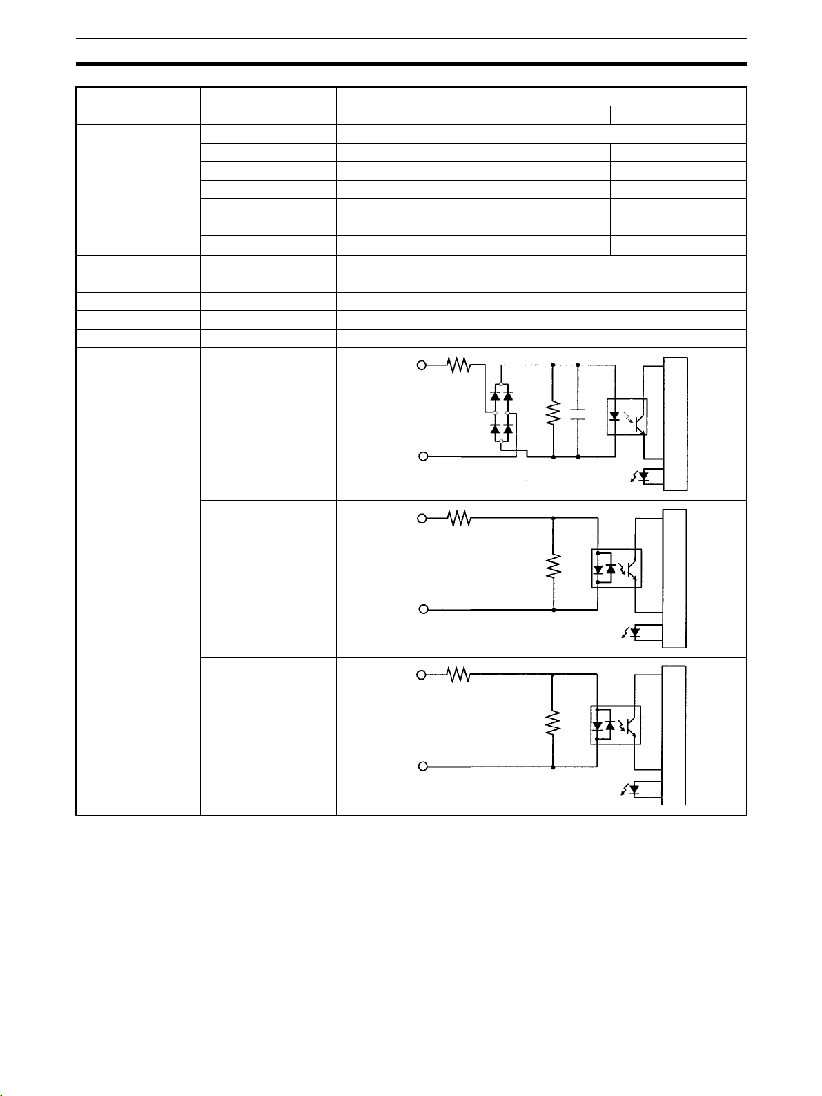
Specifications Section 2-1
Item Inputs Specification
Units with 10 I/O pts Units with 20 I/O pts Units with 32 I/O pts
Input current IN00000 to IN00001 8 mA typical
IN00002 to IN00004 6 mA typical --- --IN00002 to IN00006 --- 6 mA typical 6 mA typical
IN00005 and up 5 mA typical --- --IN00007 and up --- 5 mA typical --IN00007 --- --- 5 mA typical
IN00100 to IN00107 --- --- 5 mA typical
ON voltage/current IN00000 to IN00001 17 VDC min., 5 mA
IN00002 and up 14.4 VDC min., 3.5 mA
OFF voltage/current All 5.0 VDC max., 1.1 mA
ON delay All 1 to 80 ms max. Default: 10 ms (See note.)
OFF delay All 1 to 80 ms max. Default: 10 ms (See note.)
Circuit configuration IN00000 to IN00001
IN
2.7 kΩ
0.01
µF
1 kΩ
COM
Input LED
CPU Units with
10 I/O points:
IN00002 to IN00004
IN
3.9 kΩ
CPU Units with 20 or
32 I/O points:
820 Ω
IN00002 to IN00006
COM
Input LED
CPU Units with
10 I/O points: IN00005
IN
4.7 kΩ
CPU Units with
20 I/O points:
IN00007 to IN00011
750 Ω
CPU Units with 32
I/O points: IN00007
and
IN00100 to IN00107
COM
Input LED
Note The input time constant can be set to 1, 2, 3, 5, 10, 20, 40, or 80 ms in the PC
Setup.
Internal circuits
Internal circuits
Internal circuits
39
Page 63

Specifications Section 2-1
High-speed Counter Inputs
The following CPU Unit input bits can be used as high-speed counter inputs.
The maximum count frequency is 5 kHz in differential phase mode and
20 kHz in the other modes.
Input Function
Differential phase mode Pulse plus direction
input mode
IN00000 A-phase pulse input Pulse input Increment pulse input Increment pulse input
IN00001 B-phase pulse input Direction input Decrement pulse input Normal input
IN00002 Z-phase pulse input or hardware reset input
(IN00002 can be used as a normal input when it is not used as a high-speed counter input.)
The minimum pulse widths for inputs IN00000 (A-phase input) and IN00001
(B-phase input) are as follows:
Up/down input mode Increment mode
Pulse plus direction input mode, Up/down input
mode, Increment mode
50 µ s min.
12.5 µ s
min.
12.5 µ s
min.
Phase A
Phase B
Differential phase mode
100 µ s min.
T1
T
2 T3 T4
T
1 T2 T3 T4 : 12.5 µ s min.
The minimum pulse width for input IN00002 (Z-phase input) is as follows:
50 µs min.
Phase Z
500 µs min.
Interrupt Inputs
CPM2C PCs are equipped with inputs that can be used as interrupt inputs
(interrupt input mode or counter mode) and quick-response inputs. The minimum pulse width for these inputs is 50
µs.
In CPU Units with 10 I/O points, inputs IN00003 and IN00004 can be used as
interrupt inputs. In CPU Units with 20/32 I/O points, inputs IN00003 through
IN00006 can be used as interrupt inputs.
40
Page 64

Specifications Section 2-1
Expansion I/O Unit Input Specifications
Item Specification
Input voltage
Input impedance 4.7 kΩ
Input current 5 mA typical
ON voltage/current 14.4 VDC min., 3.5 mA
OFF voltage/current 5.0 VDC max., 1.1 mA
ON delay 1 to 80 ms max. Default: 10 ms (See note.)
OFF delay 1 to 80 ms max. Default: 10 ms (See note.)
Circuit configuration
24 VDC
+10%
/
–15%
IN
4.7 kΩ
750 Ω
COM
Input LED
Internal circuits
Note The input time constant can be set to 1, 2, 3, 5, 10, 20, 40, or 80 ms in the PC
Setup.
41
Page 65
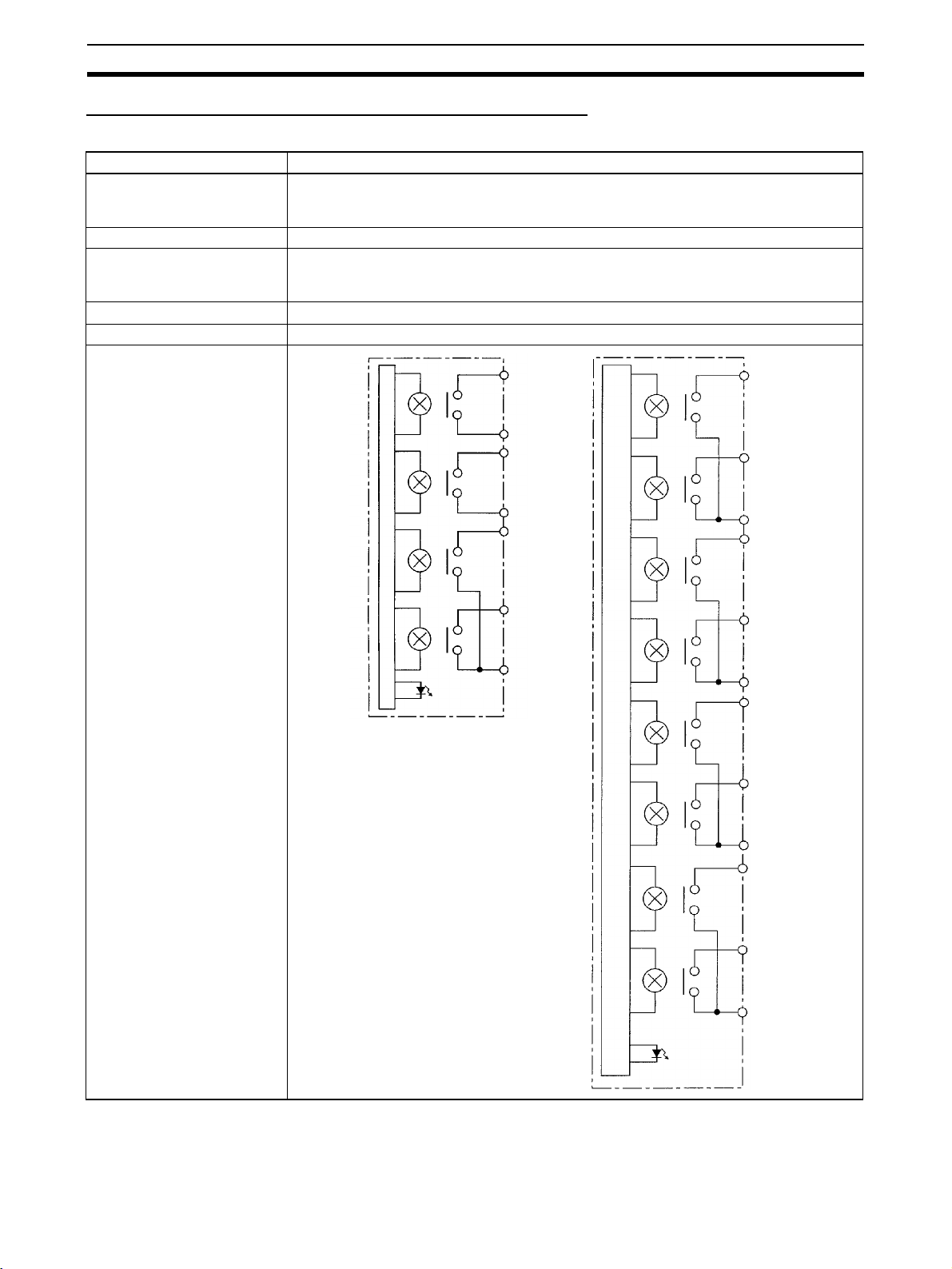
Specifications Section 2-1
CPU Unit and Expansion I/O Unit Output Specifications
Relay Outputs
Item Specification
Max. switching capacity 2 A, 250 VAC (cosφ = 1)
Min. switching capacity 10 mA, 5 VDC
Service life of relay
(See note.)
ON delay 15 ms max.
OFF delay 15 ms max.
Circuit configuration
2 A, 24 VDC
(4 A/common)
Electrical: 150,000 operations (24-VDC resistive load)
100,000 operations (240-VAC inductive load, cosφ = 0.4)
Mechanical: 20,000,000 operations
OUT 00
COM
OUT 01
OUT 00
OUT 01
Internal circuits
Output
LED
COM
OUT 02
OUT 03
COM
Internal circuits
COM
OUT 02
OUT 03
COM
OUT 04
OUT 05
COM
OUT 06
OUT 07
42
COM
Output
LED
Page 66

Specifications Section 2-1
Note The service life of relay output contacts shown in the table assumes the worst
conditions. The following graph shows the results of OMRON’s service life
tests at a switching rate of 1,800 times/hour.
120 VAC, resistive load
Life (x 104)
24 VDC, τ = 7 ms
120 VAC, cosφ = 0.4
240 VAC, cosφ = 0.4
24 VDC/240 VAC, resistive load
Switching rate: 1,800 times/hour
Contact current (A)
43
Page 67

Specifications Section 2-1
(V)
Transistor Outputs (Sinking or Sourcing)
Item Specification
Max. switching
capacity (See
note.)
Max. inrush current
Leakage current 0.1 mA max.
Residual voltage 0.8 V max.
ON delay OUT01000 and OUT01001: 20 µs max.
OFF delay OUT01000 and OUT01001: 40 µs max. at 10 to 300 mA
Fuse 1 fuse for each 2outputs (cannot be replaced by user)
CPU Units with 10 or 20 I/O Points
OUT01000 to OUT01007:40 mA/4.5 VDC to 300 mA/20.4 VDC, 300 mA (20.4 VDC to 26.4 VDC)
CPU Units with 32 I/O Points
OUT01000 to OUT01007:40 mA/4.5 VDC to 300 mA/20.4 VDC, 300 mA (20.4 VDC to 26.4 VDC)
OUT01100 to OUT01107:40 mA/4.5 VDC to 100 mA/20.4 VDC, 100 mA (20.4 VDC to 26.4 VDC)
Expansion I/O Units
OUT01@00 to OUT01@07:40 mA/4.5 VDC to 300 mA/20.4 VDC, 300 mA (20.4 VDC to 26.4 VDC)
OUT01@08 to OUT01@15:40 mA/4.5 VDC to 100 mA/20.4 VDC, 100 mA (20.4 VDC to 26.4 VDC)
When using OUT01000 or OUT01001 as a pulse output, connect a dummy resistor as required to
bring the load current between 10 and 150 mA. If the load current is below 10 mA, the ON/OFF
response time will be longer and high-speed pulses will not be output.
The transistor will heat if used at 150 mA or higher, possibly damaging elements.
0.9 A for 10 ms (charging and discharging waveform)
OUT01002 and up: 0.1 ms max.
0.1 ms max. at 0.5 to 10 mA
OUT01002 and up: 1 ms max. at 0.5 mA or more
Note The following graph shows the maximum switching capacity.
Output
current
(mA)
100/300
40
4.5 20.4 26.4
Output
voltage
!Caution Do not apply voltage in excess of the maximum switching capacity to an out-
put terminal. It may result in damage to the product or fire.
44
Page 68

Specifications Section 2-1
Item Specification
Circuit configuration
Sinking Outputs
Internal circuits
Output LED
1 A
1 A
24 VDC
OUT 00
OUT 01
OUT 06
OUT 07
COM (−)
Load
Load
Load
Load
Sourcing Outputs
Internal circuits
Output LED
1 A
1 A
COM (+)
OUT 00
OUT 01
OUT 06
OUT 07
0 VDC
Load
Load
Load
Load
45
Page 69

Specifications Section 2-1
2-1-4 AC Power Supply Unit Specifications
Item Specification
Rating 24 VDC, 600 mA
Efficiency 75% min. (at rated output)
Input conditions Rated voltage 100 to 240 VAC
Frequency 47 to 63 Hz
Allowable voltage range 85 to 264 VAC
Current 100 V 0.4 A
200 V 0.2 A
Leakage current 100 V 0.5 mA max. (at rated output)
200 V 1 mA max. (at rated output)
Inrush current 100 V 15 A (at 25°C cold start)
200 V 30 A (at 25°C cold start)
Output characteristics
Overcurrent protection Self-resetting, operates at 105% to 350% of the rated current, suspended
Overvoltage protection None
Ambient operating temperature 0 to 55°C
Ambient storage temperature –20 to 75°C
Ambient operating humidity 10% to 90% (no condensation)
Dielectric strength 2,000 V for 1 min between all inputs and GR
Insulation resistance 100 MΩ min. at 500 VDC between all outputs and any input, and between
Vibration resistance
Shock resistance
Noise terminal voltage FCC class A
Output voltage accuracy 10%/–15% (including input, load, and temperature fluctuations)
Minimum output current 30 mA
Ripple noise voltage 2% (p-p) max.
Input fluctuation 0.75% max.
Load fluctuation 4% max.
Temperature fluctuation 0.05%/°C max.
Startup time 300 ms max. (at input voltage of 100 VAC or 200 VAC and the rated out-
put)
Output hold time 10 ms (at input voltage of 100 VAC or 200 VAC and the rated output)
and independent operation
Leakage current: 10 mA
3,000 V for 1 min between all inputs and all outputs
Leakage current: 10 mA
1,000 V for 1 min between all outputs and GR
Leakage current: 10 mA
all outputs and GR
2
10 to 57 Hz, amplitude, 57 to 150 Hz, acceleration: 9.8 m/s
directions for 80 minutes according
(Time coefficient: 8 minutes × coefficient factor 10 = total time 80 min.)
2
147 m/s
3 times each in X, Y, and Z directions
in X, Y, and Z
46
Page 70

Unit Components Section 2-2
2-2 Unit Components
2-2-1 CPU Unit Components
CPU Unit Component Names
Front View
7. Communications port
2. Input terminals
3. Output terminals
CPU Unit with Relay Out-
puts via Terminal Block
7. Communications port
CPU Unit with Transistor Outputs
via Fujitsu-compatible Connector
4. Status indicators
6. Output indicators
5. Input indicators
8. Communications switch
9. Customize switch
2. Input connector
3. Output connector
CPU Unit with Transistor Outputs
via MIL Connector
4. Status indicators
6. Output indicators
5. Input indicators
8. Communications switch
9. Customize switch
2. Input connector
3. Output connector
DIP switch for Units
with 10/20 I/O points
(8) (9)
DIP switch for Units
with 32 I/O points
(8)
(9)
Top View
Right Side:
CPU Unit with Relay
Outputs via Terminal
Block
10. Battery
11. Low battery detection switch
CPU Unit with Transistor
Outputs via Fujitsu-compatible
Connector
Bottom View
1. Power supply
connector
CPU Unit with Transistor
Outputs via MIL Connector
12. Expansion I/O
connector
(output connector)
47
Page 71

Unit Components Section 2-2
CPU Unit Component Descriptions
1,2,3... 1. Power Supply Connector
Connect the power supply (24 VDC) to this connector.
2. Input Terminals/Connector
Connects the CPU Unit to external input devices.
3. Output Terminals/Connector
Connects the CPU Unit to external output devices.
4. PC Status Indicators
These indicators show the operating status of the PC, as shown in the fol-
lowing table.
Indicator Status Meaning
PWR
(green)
RUN
(green)
COMM
(yellow)
ERR/ALARM
(red)
Note CPU Units with lot numbers of 3180O or earlier (produced 31 August
2000 or earlier) also have a PRO (green) indicator that operates as
follows:
Indicator Status Meaning
PRO
(green)
5. Input Indicators
The input indicators are lit when the corresponding input terminal is ON.
The status of an input indicator will reflect the status of the input even when
that input is being used for a high-speed counter.
Note a) When interrupt inputs are used in interrupt input mode, the indica-
b) Input indicators will reflect the status of the corresponding inputs
6. Output Indicators
The output indicators are lit when the corresponding output terminal is ON.
The indicators are lit during I/O refreshing. The status of an output indicator will also reflect the status of the corresponding output when the output
is being used as a pulse output.
ON Power is being supplied to the PC.
OFF Power isn’t being supplied to the PC.
ON The PC is operating in RUN or MONITOR mode.
OFF The PC is in PROGRAM mode or a fatal error has
occurred.
Flashing Data is being transferred via the communications port
(peripheral or RS-232C).
OFF Data isn’t being transferred via communications port.
ON A fatal error has occurred. (PC operation stops.)
Flashing A non-fatal error has occurred. (PC operation contin-
ues.)
OFF Indicates normal operation.
ON The CPU Unit is set for Programming Console con-
nection.
OFF The CPU Unit is not set for Programming Console
connection.
tor may not light even when the interrupt condition is met if the input is not ON long enough.
even when the PC is stopped, but the corresponding input bits will
not be refreshed.
48
Page 72

Unit Components Section 2-2
7. Communications Port
Connects the PC to a Programming Device (including Programming Con-
soles), host computer, or standard external device. The one connector
support two different ports: Peripheral and RS-232C.
CPM2C CPU Unit
Peripheral port
(CMOS level)
RS-232C port
(RS-232C)
Use the correct Connecting Cable (CPM2C-CN111, CS1W-CN114, or
CS1W-CN118).
Note a) A C200H-PRO27-E Programming Console can be connected di-
rectly to the PC with a CS1W-CN224/CN624 Connecting Cable.
b) Use a CPM2C-CN111 or CS1W-CN114 Connecting Cable to con-
nect to the communications port as a peripheral port. The communications port can be used simultaneously as both a peripheral
port and RS-232C port by using the CPM2C-CN111 Connecting
Cable.
c) Use a CPM2C-CN111 or CS1W-CN118 Connecting Cable to con-
nect to the communications port as a RS-232C port. The communications port can be used simultaneously as both a peripheral
port and RS-232C port by using the CPM2C-CN111 Connecting
Cable
8. Communications Switch
The Communications Switch controls the communications settings for the
communications port (peripheral port and RS-232C port).
SW1 Communications settings
OFF Use the settings in the PC Setup (DM 6645 to DM 6649). If a Pro-
gramming Console is connected to the peripheral port, however,
operation will be in the Programming Console mode.
ON Use the standard settings (1 start bit, 7 data bits, 2 stop bits, even
parity, and 9,600 bps baud rate.) If a Programming Console is connected to the peripheral port, however, operation will be in the Programming Console mode.
9. Customize Switch
The Customize Switch can be used to turn ON and OFF AR 0712 in CPU
Unit memory. AR 0712 will turn ON and OFF according to the status of
SW2 regardless of the operating mode of the CPM2C.
SW2 Operation
OFF Turns OFF AR 0712.
ON Turns ON AR 0712.
Note SW2 functions as the communications switch for some Units. Refer
to
1-7 Changes in SW2 for details.
10. Battery
This battery backs up memory in CPU Units with an internal clock. The bat-
tery is connected when the Unit is shipped.
Note A battery is not included in CPU Units without an internal clock, but
a CPM2C-BAT01 Battery can be purchased separately and connected to backup memory.
11. Low Battery Detection Switch
49
Page 73

Unit Components Section 2-2
This switch enables or disables the detection of a low-battery error. When
a battery is not connected, disable low-battery detection by sliding the
switch back (toward the battery).
Switch position Low-battery detection
Forward (away from battery) Error detection enabled
Back (toward battery) Error detection disabled
Disabled
Enabled
Note Detection of a low battery is disabled by default on CPU Units without an inter-
nal clock. If the PLC Setup memory area is cleared, detection of a low battery
will be enabled and a low-battery error will be displayed. If you do mount the
optional CPM2C-BAT01 Battery, be sure to enable detection of a low battery
in the PLC Setup.
12. Expansion I/O Connector
Connects the PC’s CPU Unit to an Expansion I/O Unit or Expansion Unit.
Up to 5 Expansion I/O Units and Expansion Units can be connected to a
CPU Unit. A cover for the expansion I/O connector is included with the
CPU Unit.
50
Page 74

Unit Components Section 2-2
I/O Terminal and Connector Pin Allocation
CPU Units with Relay Outputs via Terminal Block
CPU Units with 10 I/O Points: CPM2C-10C
Inputs: IR 000 Outputs: IR 010
7
COM
IN 05
IN 04
IN 03
IN 02
IN 01
IN 00
1
OUT 00
6
2
COM
5
3
OUT 01
4
4
COM
3
5
COUT 02
2
6
OUT 03
1
7
COM
@DR-D
Shared common
51
Page 75

Unit Components Section 2-2
CPU Units with 20 I/O Points: CPM2C-20C@DR-D
Inputs: IR 000 Outputs: IR 010
COM
IN 11
IN 10
IN 09
IN 08
IN 07
IN 06
IN 05
IN 04
IN 03
IN 02
IN 01
IN 00
13
12
11
10
OUT 00
1
OUT 01
2
COM
3
COUT 02
4
10
11
12
13
5
6
7
8
9
OUT 03
COM
OUT 04
OUT 05
COM
OUT 06
OUT 07
COM
COM
9
8
7
6
5
4
3
2
1
Shared common
Shared common
Shared common
Shared common
52
Page 76

Unit Components Section 2-2
CPU Units with Transistor Outputs via Fujitsu-compatible Connector
CPU Units with 10 I/O Points: CPM2C-10C
Inputs: IR 000 Outputs: IR 010
BA
12
NC
11
NC
10
NC
9
NC
8
NC
NC
7
NC
6
NC
5
4
NC
3
NC
2
NC
1
NC
12
11
10
NC
NC
NC
COM
9
NC
8
NC
7
IN 05
6
IN 04
5
IN 03
4
IN 02
3
IN 01
2
IN 00
1
Sinking: CPM2C-10C(DTC-D Sourcing: CPM2C-10C(DT1C-D
AB
NC
NC
NC
NC
24 V
NC
NC
10
11
12
1
2
3
4
5
6
7
8
9
10
11
12
OUT 00
OUT 01
OUT 02
OUT 03
COM (−)
1
2
3
4
5
6
7
8
9
@DT@C-D
NC
NC
NC
NC
NC
NC
NC
NC
NC
COM (+24 V)
NC
NC
NC
OUT 00
OUT 01
OUT 02
OUT 03
NC
NC
NC
NC
0 V
NC
NC
AB
1
10
11
12
NC
2
NC
3
NC
4
NC
5
NC
6
NC
7
NC
8
NC
9
NC
NC
NC
NC
1
2
3
4
5
6
7
8
9
10
11
12
53
Page 77

Unit Components Section 2-2
CPU Units with 20 I/O Points: CPM2C-20C@DT@C-D
Inputs: IR 000 Outputs: IR 010
NC
NC
NC
COM
NC
NC
NC
NC
IN 11
IN 10
IN 09
IN 08
BA
12
11
10
12
NC
11
NC
10
NC
9
8
7
6
5
4
3
2
1
9
COM
8
IN 07
7
IN 06
6
IN 05
5
IN 04
4
IN 03
3
IN 02
2
IN 01
1
IN 00
Sinking: CPM2C-20C DTC-D Sourcing: CPM2C-20C DT1C-D
OUT 00
OUT 01
OUT 02
OUT 04
OUT 03
OUT 05
OUT 06
OUT 07
COM (−)
24 V
NC
NC
AB
1
1
NC
2
2
NC
3
10
11
12
NC
4
NC
5
NC
6
NC
7
NC
8
NC
9
NC
NC
NC
NC
3
4
5
6
7
8
9
10
11
12
OUT 00
OUT 01
OUT 02
OUT 03
OUT 04
OUT 05
OUT 06
OUT 07
COM (+24 V)
AB
1
2
3
4
5
6
7
8
9
10
0 V
11
NC
12
NC
10
11
12
1
NC
2
NC
3
NC
4
NC
5
NC
6
NC
7
NC
8
NC
9
NC
NC
NC
NC
54
Page 78

Unit Components Section 2-2
1
CPU Unit with 32 I/O Points: CPM2C-32CDT@C-D
Inputs: IR 000/IR 001 Outputs: IR 010/IR 011
IR 001
NC
NC
NC
COM
IN 07
IN 06
IN 05
IN 04
IN 03
IN 02
IN 01
IN 00
BA
12
12
NC
11
11
NC
10
10
NC
9
8
7
6
5
4
3
2
1
9
COM
8
IN 07
IN 06
7
IN 05
6
IN 04
5
IN 03
4
IN 02
3
IN 01
2
IN 00
1
Sinking: CPM2C-32CDTC-D Sourcing: CPM2C-32CDT1C-D
IR 010
IR 000
OUT 00
OUT 01
OUT 02
OUT 04
OUT 03
OUT 05
OUT 06
OUT 07
COM (−)
24 V
NC
NC
AB
1
2
3
4
5
6
7
8
9
10
11
12
1
2
3
4
5
6
7
8
9
10
11
12
OUT 00
OUT 01
OUT 02
OUT 04
OUT 03
OUT 05
OUT 06
OUT 07
COM (−)
24 V
NC
NC
IR 010
IR 011
OUT 00
OUT 01
OUT 02
OUT 03
OUT 04
OUT 05
OUT 06
OUT 07
COM (+24 V)
AB
1
2
3
4
5
6
7
8
9
10
0 V
11
NC
12
NC
OUT 00
1
OUT 01
2
OUT 02
3
OUT 03
4
OUT 04
5
OUT 05
6
OUT 06
7
OUT 07
8
COM (+24 V)
9
0 V
10
NC
11
NC
12
IR 01
55
Page 79
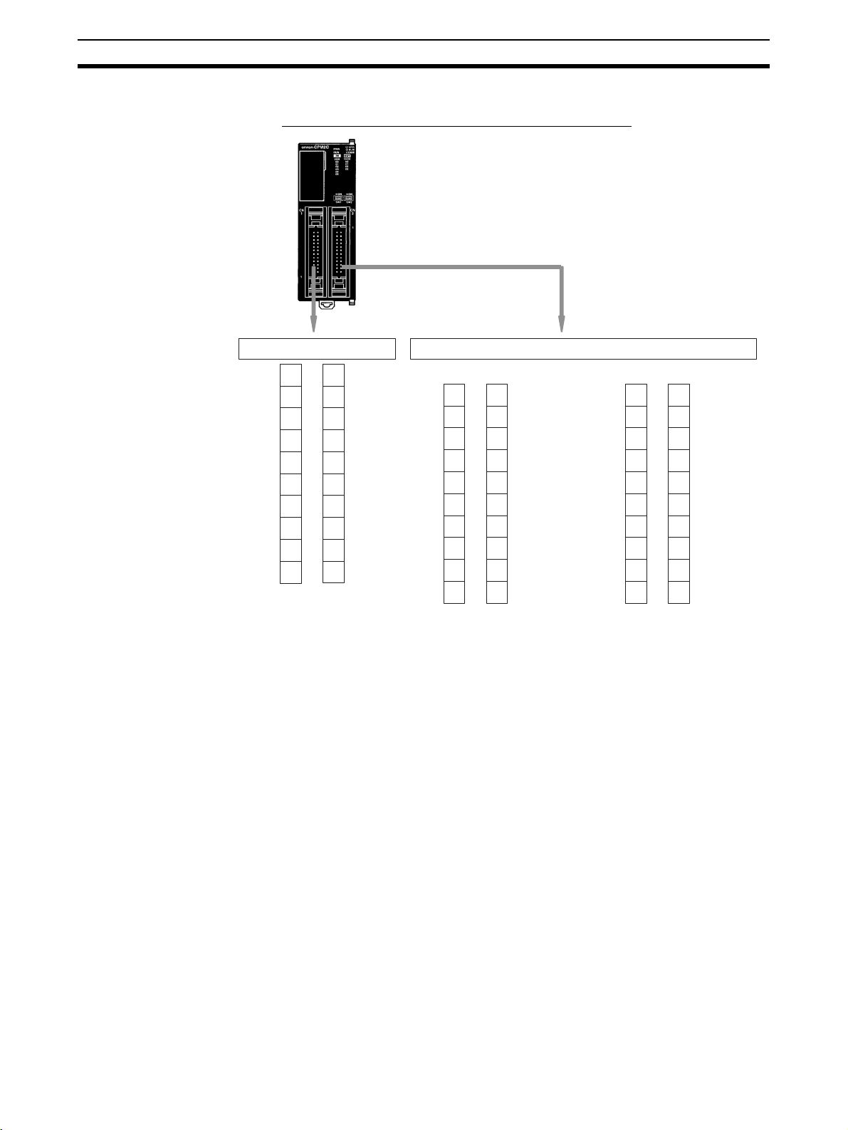
Unit Components Section 2-2
)
CPU Units with Transistor Outputs via MIL Connector
CPU Units with 10 I/O Points: CPM2C-10C
Inputs: IR 000 Outputs: IR 010
IN 00
IN 01
IN 02
IN 03
IN 04
IN 05
NC
NC
COM
NC
20
18
16
14
12
10
19
NC
17
NC
15
NC
13
NC
11
NC
9
NC
8
7
NC
6
5
NC
4
3
NC
2
1
NC
Sinking: CPM2C-10C DTM-D
1
2
4
6
8
10
12
14
16
18
20
24 V
COM (−)
NC
NC
NC
NC
OUT 03
OUT 02
OUT 01
OUT 00
NC
NC
NC
NC
NC
NC
NC
NC
NC
NC
3
5
7
9
11
13
15
17
19
@DT@M-D
Sourcing: CPM2C-10C DT1M-D
NC
NC
NC
NC
NC
NC
NC
NC
NC
NC
1
3
5
7
9
11
13
15
17
19
2
4
6
8
10
12
14
16
18
20
0 V
COM (+24 V
NC
NC
NC
NC
OUT 03
OUT 02
OUT 01
OUT 00
Note Pin 1 is in the positions given above. This differs from the indications on the
case. Be sure to wire according to the following positions.
Input connectors: Bottom of right row
Output connectors: Top of left row
56
Page 80

Unit Components Section 2-2
CPU Units with 20 I/O Points: CPM2C-20C@DT@M-D
Inputs: IR 000 Outputs: IR 010
IN 00
IN 01
IN 02
IN 03
IN 04
IN 05
IN 06
IN 07
COM
NC
20
18
16
14
12
10
19
IN 08
17
IN 09
15
IN 10
13
IN 11
11
NC
9
NC
8
7
NC
6
5
NC
4
3
COM
2
1
NC
Sinking: CPM2C-20C DTM-D Sourcing: CPM2C-20C DT1M-D
NC
NC
NC
NC
NC
NC
NC
NC
NC
NC
11
13
15
17
19
1
3
5
7
9
2
4
6
8
10
12
14
16
18
20
24 V
COM (−)
OUT 07
OUT 06
OUT 05
OUT 04
OUT 03
OUT 02
OUT 01
OUT 00
NC
NC
NC
NC
NC
NC
NC
NC
NC
NC
11
13
15
17
19
1
3
5
7
9
0 V
2
COM (+24 V)
4
OUT 07
6
OUT 06
8
OUT 05
10
OUT 04
12
OUT 03
14
OUT 02
16
18
OUT 01
20
OUT 00
Note Pin 1 is in the positions given above. This differs from the indications on the
case. Be sure to wire according to the following positions.
Input connectors: Bottom of right row
Output connectors: Top of left row
57
Page 81

Unit Components Section 2-2
CPU Units with 32 I/O Points: CPM2C-32CDT@M-D
Inputs: IR 000/IR 001 Outputs: IR 010/IR 011
IR 000
IN 00
IN 01
IN 02
IN 03
IN 04
IN 05
IN 06
IN 07
COM
NC
20
18
16
14
12
10
19
IN 00
17
IN 01
15
IN 02
13
IN 03
11
IN 04
9
IN 05
8
6
4
2
7
IN 06
5
IN 07
3
COM
1
NC
IR 001
IR 011
Sinking: CPM2C-32CDTM-D Sourcing: CPM2C-32CDT1M-D
24 V
COM (−)
OUT 07
OUT 06
OUT 05
OUT 04
OUT 03
OUT 02
OUT 01
OUT 00
1
3
5
7
9
11
13
15
17
19
2
4
6
8
10
12
14
16
18
20
24 V
COM (−)
OUT 07
OUT 06
OUT 05
OUT 04
OUT 03
OUT 02
OUT 01
OUT 00
IR 011
IR 010
0 V
COM (+24 V)
OUT 07
OUT 06
OUT 05
OUT 04
OUT 03
OUT 02
OUT 01
OUT 00
11
13
15
17
19
1
3
5
7
9
2
4
6
8
10
12
14
16
18
20
0 V
COM (+24 V)
OUT 07
OUT 06
OUT 05
OUT 04
OUT 03
OUT 02
OUT 01
OUT 00
IR 010
Note Pin 1 is in the positions given above. This differs from the indications on the
case. Be sure to wire according to the following positions.
Input connectors: Bottom of right row
Output connectors: Top of left row
58
Page 82

Unit Components Section 2-2
2-2-2 Expansion I/O Units
Expansion I/O Unit Components
Front View
Units with Relay Outputs via
Terminal Block
Units with Transistor Outputs via
Fujitsu-compatible Connector
Units with Inputs or Transistor Outputs
via Fujitsu-compatible Connector
3. Input indicators
5. Expansion I/O
connector (input)
1. Input terminals
or
2. Output terminals
4. Output
indicators
2. Output
terminals
3. Input
indicators
1. Input
connector
Units with Transistor Outputs
via MIL Connector
3. Input
indicators
1. Input
connector
4. Output
indicators
2. Output
connector
4. Output
indicators
2. Output
connector
3. Input
indicator
or
4. Output
indicator
1. Input
connector
or
2. Output
connector
Units with Inputs or Transistor
Outputs via MIL Connector
3. Input
indicator
or
4. Output
indicator
1. Input
connector
or
2. Output
connector
Side
Units with Relay
Outputs via Terminal
Block
Units with Inputs or Transistor
Outputs via Fujitsu-compatible
Connector
1,2,3... 1. Input Terminals/Connector
Connects the CPU Unit to external input devices.
2. Output Terminals/Connector
Connects the CPU Unit to external output devices.
3. Input Indicators
The input indicators are lit when the corresponding input terminal is ON.
Units with Inputs or
Transistor Outputs via
MIL Connector
7. Locking lever
6. Expansion I/O
connector (output)
7. Locking lever
59
Page 83

Unit Components Section 2-2
Note Input indicators will reflect the status of the corresponding inputs
even when the PC is stopped, but the corresponding input bits will
not be refreshed.
4. Output Indicators
The output indicators are lit when the corresponding output terminal is ON.
5. Expansion I/O Connector (Input)
Connects the Expansion I/O Unit to the CPU Unit or the previous Expansion Unit or Expansion I/O Unit.
Note The indicators are lit during I/O refreshing. The status of an output
indicator will also reflect the status of the corresponding output when
the output is being used as a pulse output.
6. Expansion I/O Connector (Output)
Connects the Expansion I/O Unit to the next Expansion I/O Unit or Expansion Unit, if necessary. Up to 5 Expansion I/O Units and Expansion Units
can be connected to a CPU Unit. Only 10 words, however, can be allocated
for input and output.
A cover for the expansion I/O connector is not included with the Expansion
I/O Unit. Use the cover included with the CPU Unit to cover the unused expansion I/O connector on the last Expansion I/O Unit or Expansion Unit in
the PC.
7. Locking Lever
Used for securing Expansion I/O Units.
60
Page 84

Unit Components Section 2-2
I/O Terminal and Connector Pin Allocation
Expansion I/O Units with Relay Outputs via Terminal Block
10 I/O Points: CPM2C-10EDR
20 I/O Points: CPM2C-20EDR
Inputs: IR word m Outputs: IR word n
Shared common
COM
IN 05
IN 04
IN 03
IN 02
IN 01
IN 00
7
6
5
4
3
2
1
OUT 00
1
2
COM
OUT 01
3
4
COM
5
OUT 02
6
OUT 03
7 COM
Shared common
8 Output Points: CPM2C-8ER
Outputs: IR word n
COM
OUT 03
OUT 02
COM
OUT 01
COM
OUT 00
7
6
5
4
3
2
1
2
3
4
5
6
71
OUT 04
COM
OUT 05
COM
OUT 06
OUT 07
COM
Inputs: IR word m Outputs: IR word n
Shared common
COM
IN 11
IN 10
IN 09
IN 08
IN 07
IN 06
IN 05
IN 04
IN 03
IN 02
IN 01
IN 00
13
12
11
10
OUT 00
1
OUT 01
2
COM
3
OUT 02
4
5
6
7
8
9
10
11
12
13
OUT 03
COM
OUT 04
OUT 05
COM
OUT 06
OUT 07
COM
COM
9
8
7
6
5
4
3
2
1
Shared common
Shared common
Shared common
Shared common
61
Page 85

Unit Components Section 2-2
Expansion I/O Units with Transistor Outputs via Fujitsu-compatible Connector
24 I/O Points: CPM2C-24EDT@C
Inputs: IR word m Outputs: IR word n
NC
NC
NC
COM
IN 15
IN 14
IN 13
IN 12
IN 11
IN 10
IN 9
IN 8
BA
12
11
10
12
NC
11
NC
10
NC
9
9
COM
8
8
IN 07
7
7
6
5
4
3
2
1
IN 06
6
IN 05
5
IN 04
4
IN 03
IN 02
3
2
IN 01
IN 00
1
Sinking: CPM2C-24EDTC
AB
NC
NC
10
11
12
1
2
3
4
5
6
7
8
9
10
11
12
OUT 00
OUT 01
OUT 02
OUT 04
OUT 03
OUT 05
OUT 06
OUT 07
COM (−)
24 V
Sourcing: CPM2C-24EDT1C
AB
0 V
NC
NC
10
11
12
1
1
NC
10
11
12
NC
2
3
NC
4
NC
NC
5
NC
6
NC
7
NC
8
NC
9
NC
NC
NC
2
3
4
5
6
7
8
9
1
NC
NC
2
3
NC
4
NC
NC
5
NC
6
NC
7
NC
8
NC
9
NC
NC
NC
OUT 00
OUT 01
OUT 02
OUT 03
OUT 04
OUT 05
OUT 06
OUT 07
COM (+24 V)
62
Page 86

Unit Components Section 2-2
32 I/O Points: CPM2C-32EDT@C
Inputs: IR word m Outputs: IR word n
NC
NC
NC
COM
IN 15
IN 14
IN 13
IN 12
IN 11
IN 10
IN 9
IN 8
BA
12
12
NC
11
10
NC
NC
COM
9
8
IN 07
7
IN 06
IN 05
6
IN 04
5
4
IN 03
3
IN 02
2
IN 01
1
IN 00
11
10
9
8
7
6
5
4
3
2
1
Sinking: CPM2C-32EDTC
AB
OUT 00
OUT 01
OUT 02
OUT 04
OUT 03
OUT 05
OUT 06
OUT 07
COM (−)
24 V
NC
NC
1
2
3
4
5
6
7
8
9
10
11
12
1
2
3
4
5
6
7
8
9
10
11
12
OUT 08
OUT 09
OUT 10
OUT 11
OUT 12
OUT 13
OUT 14
OUT 15
COM (−)
24 V
NC
NC
Sourcing: CPM2C-32EDT1C
AB
0 V
NC
NC
1
2
3
4
5
6
7
8
9
10
11
12
OUT 00
OUT 01
OUT 02
OUT 03
OUT 04
OUT 05
OUT 06
OUT 07
COM (+24 V)
1
OUT 08
2
OUT 09
3
OUT 10
OUT 11
4
5
OUT 12
6
OUT 13
7
OUT 14
8
OUT 15
9
COM (+24 V)
10
0 V
11
NC
12
NC
63
Page 87

Unit Components Section 2-2
16 Input Points: CPM2C-16EDC8 Input Points: CPM2C-8EDC
Inputs: IR word m
BA
NC
12
NC
11
NC
10
NC
9
NC
8
NC
7
NC
6
NC
5
NC
4
NC
3
NC
2
NC
1
8 Output Points: CPM2C-8ET@C
12
11
10
Inputs: IR word m
BA
12
11
10
12
NC
11
NC
10
NC
9
9
8
7
6
5
4
3
2
1
COM
8
IN 07
7
IN 06
6
IN 05
5
IN 04
IN 03
4
3
IN 02
2
IN 01
1
IN 00
NC
NC
NC
9
COM
8
IN 07
7
IN 06
6
IN 05
5
IN 04
IN 03
4
IN 02
3
IN 01
2
IN 00
1
NC
NC
NC
COM
IN 15
IN 14
IN 13
IN 12
IN 11
IN 10
IN 09
IN 08
Outputs: IR word n
Sinking: CPM2C-8ETC Sourcing: CPM2C-8ET1C
A
OUT 00
OUT 01
OUT 02
OUT 03
OUT 04
OUT 05
OUT 06
OUT 07
COM ( )
24 V
NC
NC
10
11
12
B
1
1
2
2
NC
3
3
NC
4
4
NC
5
5
NC
6
6
NC
7
7
NC
10
11
12
NC
8
9
NC
NC
NC
NC
8
9
OUT 00NC
OUT 01
OUT 02
OUT 03
OUT 04
OUT 05
OUT 06
OUT 07
COM (+24 V)
0 V
NC
NC
A
1
2
3
4
5
6
7
8
9
10
11
12
10
11
12
B
1
NC
2
NC
3
NC
4
NC
5
NC
6
NC
7
NC
8
NC
9
NC
NC
NC
NC
64
Page 88

Unit Components Section 2-2
16 Output Points: CPM2C-16ET@C
Outputs: IR word n
Sinking: CPM2C-16ETC Sourcing: CPM2C-16ET1C
A
B
1
2
3
4
5
6
7
8
9
OUT 08
1
OUT 09
2
OUT 10
3
OUT 11
4
OUT 12
5
OUT 13
6
OUT 14
7
OUT 15
8
COM (+24 V)
9
0 V
10
NC
11
NC
12
OUT 00
OUT 01
OUT 02
OUT 03
OUT 04
OUT 05
OUT 06
OUT 07
COM (−)
24 V
NC
NC
10
11
12
B
A
OUT 08
1
1
OUT 09
2
2
OUT 10
3
3
OUT 11
4
4
OUT 12
5
5
OUT 13
6
6
OUT 14
7
7
OUT 15
8
8
9
9
10
11
12
COM (−)
24 V
NC
NC
OUT 00
OUT 01
OUT 02
OUT 03
OUT 04
OUT 05
OUT 06
OUT 07
COM (+24 V)
0 V
NC
NC
10
11
12
65
Page 89

Unit Components Section 2-2
Expansion I/O Units with Transistor Outputs via MIL Connector
24 I/O Points: CPM2C-24EDT@M
Inputs: IR word m Outputs: IR word n
IN 00
IN 01
IN 02
IN 03
IN 04
IN 05
IN 06
IN 07
COM
NC
20
18
16
14
12
10
19
IN 08
17
IN 09
15
IN 10
13
IN 11
11
NC
9
NC
8
7
NC
6
5
NC
4
3
COM
2
1
NC
Sinking: CPM2C-24EDTM
1
2
4
6
8
10
12
14
16
18
20
24 V
COM (−)
OUT 07
OUT 06
OUT 05
OUT 04
OUT 03
OUT 02
OUT 01
OUT 00
NC
NC
NC
NC
NC
NC
NC
NC
NC
NC
3
5
7
9
11
13
15
17
19
Sourcing: CPM2C-24EDT1M
1
2
NC
NC
NC
NC
NC
NC
NC
NC
NC
NC
3
5
7
9
11
13
15
17
19
0 V
4
COM (+24 V)
6
OUT 07
8
OUT 06
10
OUT 05
12
OUT 04
14
OUT 03
16
OUT 02
18
OUT 01
20
OUT 00
Note Pin 1 is in the positions given above. This differs from the indications on the
case. Be sure to wire according to the following positions.
Input connectors: Bottom of right row
Output connectors: Top of left row
66
Page 90

Unit Components Section 2-2
32 I/O Points: CPM2C-32EDT@M
Inputs: IR word m Outputs: IR word n
IN 00
IN 01
IN 02
IN 03
IN 04
IN 05
IN 06
IN 07
COM
NC
20
18
16
14
12
10
19
IN 08
17
IN 09
15
IN 10
13
IN 11
11
IN 12
9
IN 13
8
7
IN 14
6
5
IN 15
4
3
COM
2
1
NC
Sinking: CPM2C-32EDTM
1
24 V
COM (−)
OUT 15
OUT 14
OUT 13
OUT 12
OUT 11
OUT 10
OUT 09
OUT 08
3
5
7
9
11
13
15
17
19
2
4
6
8
10
12
14
16
18
20
24 V
COM (−)
OUT 07
OUT 06
OUT 05
OUT 04
OUT 03
OUT 02
OUT 01
OUT 00
Sourcing: CPM2C-32EDT1M
1
0 V
COM (+24 V)
OUT 15
OUT 14
OUT 13
OUT 12
OUT 11
OUT 10
OUT 09
OUT 08
3
5
7
9
11
13
15
17
19
2
0 V
4
COM (+24 V)
6
OUT 07
8
OUT 06
10
OUT 05
12
OUT 04
14
OUT 03
16
OUT 02
18
OUT 01
20
OUT 00
Note Pin 1 is in the positions given above. This differs from the indications on the
case. Be sure to wire according to the following positions.
Input connectors: Bottom of right row
Output connectors: Top of left row
67
Page 91

Unit Components Section 2-2
8 Input Points: CPM2C-8EDM
8ED
Inputs: IR word m
20
IN 00
18
IN 01
16
IN 02
14
IN 03
12
IN 04
10
IN 05
NC
8
6
4
2
IN 06
IN 07
COM
19
17
15
13
11
16 Input Points: CPM2C-16EDM
16ED
Inputs: IR word m
20
NC
NC
NC
NC
NC
9
NC
7
NC
5
NC
3
NC
1
NC
IN 00
IN 01
IN 02
IN 03
IN 04
IN 05
IN 06
IN 07
COM
NC
18
16
14
12
10
19
IN 08
17
IN 09
15
IN 10
13
IN 11
11
IN 12
9
IN 13
8
6
4
2
7
IN 14
5
IN 15
3
COM
1
NC
8 Output Points: CPM2C-8ET@M
Sinking: CPM2C-8ETM Sourcing: CPM2C-8ET1M
1
NC
3
NC
5
NC
7
NC
9
NC
11
NC
13
NC
15
NC
17
NC
19
NC
2
4
6
8
10
12
14
16
18
20
Outputs: IR word n
24 V
COM (−)
OUT 07
OUT 06
OUT 05
OUT 04
OUT 03
OUT 02
OUT 01
OUT 00
NC
NC
NC
NC
NC
NC
NC
NC
NC
NC
11
13
15
17
19
1
2
0 V
3
4
COM (+24 V)
5
6
OUT 07
7
8
OUT 06
9
10
OUT 05
12
OUT 04
14
OUT 03
16
OUT 02
18
OUT 01
20
OUT 00
68
Page 92

Unit Components Section 2-2
16 Output Points: CPM2C-16ET@M
Outputs: IR word n
Sinking: CPM2C-16ETM Sourcing: CPM2C-16ET1M
24 V
COM (−)
OUT 15
OUT 14
OUT 13
OUT 12
OUT 11
OUT 10
OUT 09
OUT 08
1
3
5
7
9
11
13
15
17
19
2
4
6
8
10
12
14
16
18
20
24 V
COM (−)
OUT 07
OUT 06
OUT 05
OUT 04
OUT 03
OUT 02
OUT 01
OUT 00
2-2-3 CPM2C-MAD11 Analog I/O Unit
Front View
3. Expansion I/O
connector (input)
2. DIP switch
0 V
COM (+24 V)
OUT 15
OUT 14
OUT 13
OUT 12
OUT 11
OUT 10
OUT 09
OUT 08
1
3
5
7
9
11
13
15
17
19
2
4
6
8
10
12
14
16
18
20
Right Side
0 V
COM (+24 V)
OUT 07
OUT 06
OUT 05
OUT 04
OUT 03
OUT 02
OUT 01
OUT 00
5. Locking lever
4. Expansion I/O
connector (output)
1. Analog I/O terminals
1,2,3... 1. Analog I/O Terminals
Connect the CPU Unit to analog input and analog output devices.
5. Locking lever
69
Page 93
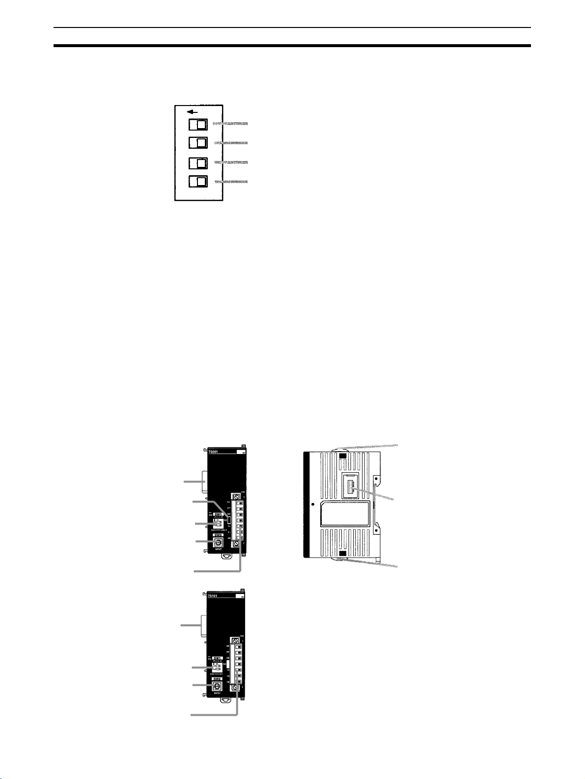
Unit Components Section 2-2
p
4
2. DIP Switch
Used to switch between voltage and current input, and to perform average
processing.
ON
1
2
3
4
3. Expansion I/O Connector (Input)
Connects the Analog I/O Unit to the CPU Unit or previous Expansion Unit
or Expansion I/O Unit.
4. Expansion I/O Connector (Output)
Connects the Analog I/O Unit to the next Expansion I/O Unit or Expansion
Unit, if necessary. Up to 5 Expansion I/O Units and Expansion Units can
be connected to a CPU Unit. Only 10 words, however, can be allocated for
input and output respectively.
A cover for the expansion I/O connector is not included with the Expansion
Unit. Use the cover included with the CPU Unit to cover the unused expansion I/O connector on the last Expansion I/O Unit or Expansion Unit in the
PC.
5. Locking Lever
Used for securing Expansion Units.
Average processing for analog input 0
(OFF: Average processing not performed; ON: Average processing performed)
Average processing for analog input 1
(OFF: Average processing not performed; ON: Average processing performed)
Input type for analog input 0
(OFF: Voltage input; ON: Current input)
Input type for analog input 1
(OFF: Voltage input; ON: Current input)
2-2-4 CPM2C-TS001/TS101 Temperature Sensor Units
Front View
CPM2C-TS001
4. Expansion I/O connector (input)
Cold junction compensator
2. DIP switch
3. Rotary switch
1. Temperature input terminals
CPM2C-TS101
. Expansion I/O connector (input)
2. DIP switch
3. Rotary switch
Right Side
6. Locking lever
5. Expansion I/O connector (output)
6. Locking lever
1. Tem
erature input terminals
70
Page 94

Unit Components Section 2-2
1,2,3... 1. Temperature Input Terminals
Connect to a thermocouple or a platinum resistance thermometer.
2. DIP Switch
Sets the temperature unit (
used.
3. Rotary Switch
Sets the temperature range.
CPM2C-TS001
Set value Thermocouple Range (°C) Range (°F)
0 K –200 to 1,300 –300 to 2,300
1 0.0 to 500.0 0.0 to 900.0
2 J –100 to 850 –100 to 1,500
3 0.0 to 400.0 0.0 to 750.0
4 to F --- Setting not possible
°C or °F) and the number of decimal places
Temperature unit for temperature input 0
OFF: C; ON: F
Number of decimal places used
OFF: Normal (0 or 1); ON: 2
CPM2C-TS101
Set value Platinum
resistance
thermometer
0 Pt100 –200.0 to 650.0 –300.0 to 1,200.0
1 JPt100 –200.0 to 650.0 –300.0 to 1,200.0
2 to F --- Setting not possible
Range (°C) Range (°F)
4. Expansion I/O Connector (Input)
Connects the Temperature Sensor Unit to the CPU Unit or the previous Expansion I/O Unit or Expansion Unit.
5. Expansion I/O Connector (Output)
Connects the Temperature Sensor Unit to the next Expansion I/O Unit or
Expansion Unit, if necessary. Up to 5 Expansion I/O Units and Expansion
Units can be connected to a CPU Unit. Only 10 words, however, can be
allocated for input and output.
A cover for the expansion I/O connector is not included with the Expansion
Unit. Use the cover included with the CPU Unit to cover the unused expansion I/O connector on the last Expansion I/O Unit or Expansion Unit in the
PC.
6. Locking Lever
Used for securing Expansion Units.
71
Page 95

Unit Components Section 2-2
2-2-5 CPM2C-SRT21 CompoBus/S I/O Link Unit
3. LED indicators
4. Expansion I/O connector (input)
2. DIP switch
1. CompoBus/S terminals
1,2,3... 1. CompoBus/S Terminals
Front View
Include the CompoBus/S communications data high/low terminal, and NC
terminals. Power is supplied to the Unit internally.
2. DIP Switch
The DIP switch sets the Unit’s node address, sets the communications
mode, and determines whether or not the outputs will be cleared in the
event of a communications error.
Right Side
6. Locking lever
5. Expansion I/O connector (output)
6. Locking lever
Pin(s) Function
1 to 4
(labeled
1, 2, 4,
and 8)
DR ON: Long-distance Communications Mode
HOLD ON: Retain inputs when a communications error occurs.
These pins set the Unit’s node address using the DIP switch pins as
binary digits. (1 = ON)
0: 0000 1: 0001 2: 0010 3: 0011
4: 0100 5: 0101 6: 0110 7: 0111
8: 1000 9: 1001 10: 1010 11: 1011
12: 1100 13: 1101 14: 1110 15: 1111
OFF: High-speed Communications Mode
(See note.)
OFF: Clear inputs when a communications error occurs.
72
Note The Long-distance Communications Mode can be used only when connected
to one of the following Master Units: C200HW-SRM21-V1, CQM1-SRM21-V1,
SRM1-C0@-V2, or CPM2C-S.
3. LED Indicators
These indicators show the status of CompoBus/S communications.
Indicator Status Meaning
COMM
(yellow)
ERR
(red)
ON Communications in progress.
OFF Communications error or stopped.
ON A communications error has occurred.
OFF Indicates normal or no communications.
4. Expansion I/O Connector (Input)
Connects the CompoBus/S I/O Link Unit to the CPU Unit or the previous
Expansion I/O Unit or Expansion Unit.
5. Expansion I/O Connector (Output)
Connects the CompoBus/S I/O Link Unit to the next Expansion I/O Unit or
Expansion Unit, if necessary. Up to 5 Expansion I/O Units and Expansion
Page 96

Unit Components Section 2-2
Units can be connected to a CPU Unit. Only 10 words, however, can be
allocated for input and output respectively.
A cover for the expansion I/O connector is not included with the Expansion
Unit. Use the cover included with the CPU Unit to cover the unused expansion I/O connector on the last Expansion I/O Unit or Expansion Unit in the
PC.
6. Locking Lever
Used for securing Expansion Units.
2-2-6 CPM2C-CIF21 Simple Communications Unit
Front Side
1. RS-422/RS-485 port
4. RS-422/RS-485 switch (SW1)
6. DM area setting switch
2. RS-232C port
8. Connector
Top
3. Terminating resistance
switches (SW4)
Note The CPM2C-CIF21 can be used only with the CPM2C.
7. Status indicators
Cover
5. Communications switch (SW3)
Use a flat-blade screwdriver
or similar device if the cover
is difficult to remove.
73
Page 97

Unit Components Section 2-2
1,2,3... 1. RS-422/RS-485 Port
Connects CompoWay/F general-purpose communications components
and SYSWAY Temperature Controllers and Digital Panel Meters.
RS-422 Pin Assignments
RDA−
Receive data (input)
RDB+
SDA−
Transmit data (output)
SDB+
NC
Max. line length: 500 m
RS-422 Connection Example
CPM2C-CIF21
SDB+
RDB+
SDA−
RDB+ SDB+
RDA−
Communications
component
RDA−
SDA−
RS-485 Pin Assignments
RDA−
Transmit/receive data (I/O)
RDB+
SDA−
Transmit/receive data (I/O)
SDB+
NC
Max. line length: 500 m
RS-485 Connection Example
CPM2C-CIF21
SDB+
SDA−
RDB+
RDA−
Communications
component
RDB+
RDA−
Note Confirm polarity before connecting RS-422/485 lines. Some devices require
that SDA/SDB or RDA/RDB and the +/– signal be reversed.
2. RS-232C Port
Connects to an RS-232C interface on a computer, PT (Programmable Terminal), etc.
Pin Assignments
5 CTS
4 RTS
3 RxD
2 TxD
1 NC
Top port Signal
conversion
9 SG
8 NC
7 NC
6 NC
Changes levels between CMOS (CPU Unit) and RS-422
(general-purpose communications components).
RS-422 (general-purpose communications components) insulated using DC/DC converter or photocoupler.
Function Conversion between CPU Unit and Host Link
General-purpose communications components are
CompoWay/F or SYSWAY components, which support
general-purpose serial communications.
Bottom port Signal
conversion
Outputs the RS-232C interface directly from the CPU
Unit.
Function Host Link, no-protocol, 1:1 link, or 1:1 NT Link
3. Terminating Resistance Switches (SW4)
Turn ON both SW4-1 and SW4-2 on both ends of the RS-422/RS-485
transmission path. These switches are set to OFF at the factory.
74
Page 98

Unit Components Section 2-2
Terminating Resistance
Ω (combined
Ω (combined
Ω min)
Ω min)
RS-422 Setting RS-485 Setting
SW1 SW1
ON 1 2 3 4
ON 1 2 3 4
Note The default setting is for 2-wire RS-485 communications. Do not turn ON both
SW4
Resistance
connected
Resistance
not connected
RS-422: 235
resistance must be 110
RS-485: 118
resistance must be 54
4. RS-422/RS-485 Switch (SW1)
Switches the RS-485 interface and sets RS/CS controls for the RS-485 in-
terface.
Pin on SW1 RS-422 RS-485
1OFFON
2OFFON
3ONOFF
4OFFON
SW1-3 and SW1-4 at the same time. Doing so will destroy internal circuits.
SW3
O
N
1
2
3
4
5
6
7
8
All pins are turned
OFF at the factory.
5. Communications Switch (SW3)
Pin Setting OFF ON
1 Baud rate with CPU Unit 9,600 bps 19,200 bps
2 Baud rate with components Normal 9,600 bps 19,200 bps
High-speed 38,400 bps 57,600 bps
3 Data length with components 7 bits 8 bits
4 Parity 1 setting with components Yes None
5 Parity 2 setting with components Even Odd
6 Stop bits with components 2 1
7 Not used. (Always leave pin 7 OFF.) Leave OFF. --8 Component communications speed Normal High-speed
Note a) Pins 3 to 6 on SW3 are used to set communications between gen-
eral-purpose communications components and the Simple Communications Unit.
b) Turn OFF pin 7 on SW3. Operation may not be correct if this pin is
turned ON.
75
Page 99

Unit Components Section 2-2
6. DM Area Setting Switch (SW2)
Sets the starting word in the DM Area
Setting Starting word in DM Area
0 DM 0000
1 DM 0100
2 DM 0200
3 DM 0300
4 DM 0400
5 DM 0500
6 DM 0600
7 DM 0700
8 DM 0800
9 DM 0900
A DM 1000
B DM 1100
C DM 1200
D DM 1300
E DM 1400
F DM 1500
7. Status Indicators
Indicate the operating status of the Simple Communications Unit.
Label Status Meaning
RUN Lit Communications established between Simple Communica-
tions Unit and CPU Unit. Simple Communications Unit oper-
ating.
Not lit Simple Communications Unit not operating.
Flashing Communications between Simple Communications Unit and
ERR/ALM Lit Fatal error occurred. (Unit operation stops.)
Flashing Non-fatal error occurred. (Unit operation continues.)
Not lit Unit operating normally.
COMM1 Flashing Transferring data between Simple Communications Unit and
Not lit Not transferring data
COMM2 Flashing Transferring data between Simple Communications Unit and
Not lit Not transferring data
CPU Unit either not established or interrupted.
CPU Unit
connected components
76
Page 100

Unit Components Section 2-2
8. Connector
Connects to CPU Unit communications port.
RS-422 Interface Block Diagram
C5V
TxD
C5V
C0V
C5V
C5V
SW1
C5V
SW1
4
3
C0V
C0V
0 V
5 V
SE
5 V
RxD
5 V
0 V
2-2-7 CPM2C-CIF01-V1 Peripheral/RS-232C Adapter Unit
Front View
Do not use the CPM2C-CIF01-V1 with any PC other than the
1. Peripheral port
2. Cable switch (SW1)
3. RS-232C port
CPM2C. Do not connect another CPM2C-CIF01-V1 or the
CPM2C-CIF11 to the CPM2C-CIF01-V1. The CPM2C-CN111 can
be connected to the CPM2C-CIF01, but the peripheral port and
the RS-232C port of the CPM2C-CN111 cannot be used
simultaneously. If an attempt to use these ports simultaneously is
made, communications will not be performed properly, and this
may result in malfunction of equipment.
*: The CPM2C-CIF01 does not have a cable switch (SW1).
SDB
SDA
SW4
12
RDB
RDA
SW4
4. Connector
1,2,3... 1. Peripheral Port
Used to connect to Programming Devices (including Programming Consoles), host computers, or general-purpose external devices. Use a special connecting cable (CS1W-CN114, CS1W-CN118) for connections.
With the CPM2C-CIF01-V1, the cable switch (SW1) can be turned ON to
enable connecting to a personal computer with a CS1W-CN226/CN626
Connecting Cable.
Note a) The C200H-PRO27-E Programming Console can be connected
directly to the CPM2C’s CPU Unit using a special connecting cable (CS1W-CN224/624).
77
 Loading...