


Cat. No. W317-E1-11
SYSMAC
CPM1A
Programmable Controllers
OPERATION MANUAL
CPM1A Programmable Controllers
Operation Manual
Revised October 2007

iv

Notice:
OMRON products are manufactured for use according to proper procedures by a qualified operator
and only for the purposes described in this manual.
The following conventions are used to indicate and classify precautions in this manual. Always heed
the information provided with them. Failure to heed precautions can result in injury to people or damage to property.
DANGER Indicates an imminently hazardous situation which, if not avoided, will result in death or
!
serious injury. Additionally, there may be severe property damage.
WARNING Indicates a potentially hazardous situation which, if not avoided, could result in death or
!
serious injury. Additionally, there may be severe property damage.
Caution Indicates a potentially hazardous situation which, if not avoided, may result in minor or
!
moderate injury, or property damage.
OMRON Product References
All OMRON products are capitalized in this manual. The word “Unit” is also capitalized when it refers
to an OMRON product, regardless of whether or not it appears in the proper name of the product.
The abbreviation “Ch,” which appears in some displays and on some OMRON products, often means
“word” and is abbreviated “Wd” in documentation in this sense.
The abbreviation “PC” means Programmable Controller and is not used as an abbreviation for anything else.
Visual Aids
The following headings appear in the left column of the manual to help you locate different types of
information.
OMRON, 1997
All rights reserved. No part of this publication may be reproduced, stored in a retrieval system, or transmitted, in any
form, or by any means, mechanical, electronic, photocopying, recording, or otherwise, without the prior written permission of OMRON.
No patent liability is assumed with respect to the use of the information contained herein. Moreover, because OMRON is
constantly striving to improve its high-quality products, the information contained in this manual is subject to change
without notice. Every precaution has been taken in the preparation of this manual. Nevertheless, OMRON assumes no
responsibility for errors or omissions. Neither is any liability assumed for damages resulting from the use of the information contained in this publication.
Note Indicates information of particular interest for efficient and convenient operation
of the product.
1, 2, 3... 1. Indicates lists of one sort or another, such as procedures, checklists, etc.
v

vi

TABLE OF CONTENTS
PRECAUTIONS xv. . . . . . . . . . . . . . . . . . . . . . . . . . . . . . . . .
1 Intended Audience xvi. . . . . . . . . . . . . . . . . . . . . . . . . . . . . . . . . . . . . . . . . . . . . . . . . . . . . . . . . . .
2 General Precautions xvi. . . . . . . . . . . . . . . . . . . . . . . . . . . . . . . . . . . . . . . . . . . . . . . . . . . . . . . . . .
3 Safety Precautions xvi. . . . . . . . . . . . . . . . . . . . . . . . . . . . . . . . . . . . . . . . . . . . . . . . . . . . . . . . . . .
4 Operating Environment Precautions xvii. . . . . . . . . . . . . . . . . . . . . . . . . . . . . . . . . . . . . . . . . . . . .
5 Application Precautions xviii. . . . . . . . . . . . . . . . . . . . . . . . . . . . . . . . . . . . . . . . . . . . . . . . . . . . . .
6 EC Directives xxi. . . . . . . . . . . . . . . . . . . . . . . . . . . . . . . . . . . . . . . . . . . . . . . . . . . . . . . . . . . . . .
7 Revised Specifications xxiii. . . . . . . . . . . . . . . . . . . . . . . . . . . . . . . . . . . . . . . . . . . . . . . . . . . . . . .
SECTION 1
Introduction 1. . . . . . . . . . . . . . . . . . . . . . . . . . . . . . . . . . . .
1-1 CPM1A Features and Functions 2. . . . . . . . . . . . . . . . . . . . . . . . . . . . . . . . . . . . . . . . . . . .
1-2 System Configuration 10. . . . . . . . . . . . . . . . . . . . . . . . . . . . . . . . . . . . . . . . . . . . . . . . . . . . .
SECTION 2
Unit Specifications and Components 21. . . . . . . . . . . . . . . .
2-1 Specifications 22. . . . . . . . . . . . . . . . . . . . . . . . . . . . . . . . . . . . . . . . . . . . . . . . . . . . . . . . . . .
2-2 Unit Components 31. . . . . . . . . . . . . . . . . . . . . . . . . . . . . . . . . . . . . . . . . . . . . . . . . . . . . . . .
SECTION 3
Installation and Wiring 41. . . . . . . . . . . . . . . . . . . . . . . . . . .
3-1 Design Precautions 42. . . . . . . . . . . . . . . . . . . . . . . . . . . . . . . . . . . . . . . . . . . . . . . . . . . . . . .
3-2 Selecting an Installation Site 43. . . . . . . . . . . . . . . . . . . . . . . . . . . . . . . . . . . . . . . . . . . . . . .
3-3 Installing the CPM1A 45. . . . . . . . . . . . . . . . . . . . . . . . . . . . . . . . . . . . . . . . . . . . . . . . . . . . .
3-4 Wiring and Connections 50. . . . . . . . . . . . . . . . . . . . . . . . . . . . . . . . . . . . . . . . . . . . . . . . . . .
SECTION 4
Using Peripheral Devices 77. . . . . . . . . . . . . . . . . . . . . . . . . .
4-1 Support Software Capabilities 78. . . . . . . . . . . . . . . . . . . . . . . . . . . . . . . . . . . . . . . . . . . . . .
4-2 Using a Programming Console 84. . . . . . . . . . . . . . . . . . . . . . . . . . . . . . . . . . . . . . . . . . . . .
4-3 Programming Console Operations 90. . . . . . . . . . . . . . . . . . . . . . . . . . . . . . . . . . . . . . . . . . .
4-4 Programming Example 112. . . . . . . . . . . . . . . . . . . . . . . . . . . . . . . . . . . . . . . . . . . . . . . . . . . .
SECTION 5
Test Runs and Error Processing 119. . . . . . . . . . . . . . . . . . . .
5-1 Initial System Checks and Test Run Procedure 120. . . . . . . . . . . . . . . . . . . . . . . . . . . . . . . . .
5-2 The CPM1A Cycle 122. . . . . . . . . . . . . . . . . . . . . . . . . . . . . . . . . . . . . . . . . . . . . . . . . . . . . . .
5-3 Self-diagnosis Functions 123. . . . . . . . . . . . . . . . . . . . . . . . . . . . . . . . . . . . . . . . . . . . . . . . . .
5-4 Programming Console Operation Errors 125. . . . . . . . . . . . . . . . . . . . . . . . . . . . . . . . . . . . . .
5-5 Programming Errors 125. . . . . . . . . . . . . . . . . . . . . . . . . . . . . . . . . . . . . . . . . . . . . . . . . . . . . .
5-6 Troubleshooting Flowcharts 127. . . . . . . . . . . . . . . . . . . . . . . . . . . . . . . . . . . . . . . . . . . . . . . .
5-7 Maintenance Inspections 135. . . . . . . . . . . . . . . . . . . . . . . . . . . . . . . . . . . . . . . . . . . . . . . . . .
5-8 Handling Precautions 136. . . . . . . . . . . . . . . . . . . . . . . . . . . . . . . . . . . . . . . . . . . . . . . . . . . . .
SECTION 6
Expansion Memory Unit 137. . . . . . . . . . . . . . . . . . . . . . . . . .
6-1 Overview 138. . . . . . . . . . . . . . . . . . . . . . . . . . . . . . . . . . . . . . . . . . . . . . . . . . . . . . . . . . . . . .
6-2 Specifications and Nomenclature 139. . . . . . . . . . . . . . . . . . . . . . . . . . . . . . . . . . . . . . . . . . .
6-3 Handling 140. . . . . . . . . . . . . . . . . . . . . . . . . . . . . . . . . . . . . . . . . . . . . . . . . . . . . . . . . . . . . . .
vii

TABLE OF CONTENTS
Appendices
A Standard Models 147. . . . . . . . . . . . . . . . . . . . . . . . . . . . . . . . . . . . . . . . . . . . . . . . . . . . . . . . . . .
B Dimensions 151. . . . . . . . . . . . . . . . . . . . . . . . . . . . . . . . . . . . . . . . . . . . . . . . . . . . . . . . . . . . . . . .
Glossary 159. . . . . . . . . . . . . . . . . . . . . . . . . . . . . . . . . . . . . . .
Index 175. . . . . . . . . . . . . . . . . . . . . . . . . . . . . . . . . . . . . . . . . .
Revision History 179. . . . . . . . . . . . . . . . . . . . . . . . . . . . . . . . .
viii

About this Manual:
The CPM1A is a compact, high-speed Programmable Controller (PC) designed for control operations in
systems requiring from 10 to 100 I/O points per PC. There are two manuals describing the setup and
operation of the CPM1A: the CPM1A Operation Manual (this manual) and the CPM1/CPM1A/CPM2A/
CPM2C/SRM1(-V2) Programming Manual (W353).
This manual describes the system configuration and installation of the CPM1A and provides a basic
explanation of operating procedures for the Programming Consoles. It also introduces the capabilities of
the SYSMAC Support Software (SSS). Read this manual first to acquaint yourself with the CPM1A.
The CPM1/CPM1A/CPM2A/CPM2C/SRM1(-V2) Programming Manual (W353) provides detailed
descriptions of the CPM1A’s programming functions. The SYSMAC Support Software Operation Manu-
als: Basics and C-series PCs (W247 and W248) provide descriptions of SSS operations for the CPM1A
and other SYSMAC C-series PCs. The SYSMAC-CPT Support Software Quick Start Guide (W332) and
User Manual (W333) provide descriptions of ladder diagram operations in the Windows environment. The
WS02-CXPC1-E-V72 CX-Programmer Ver. 7.2 Operation Manual (W446) and the WS02-CXPC1-E-V7
CX-Programmer Ver. 7.2 Operation Manual: Function Blocks/Structured Text (W447) provide details of
operations for the WS02-CXPC1-E CX-Programmer. The CompoBus/S Operation Manual (W266) provides CompoBus/S communications specifications and describes CompoBus/S application methods.
Please read this manual carefully and be sure you understand the information provide before attempting
to install and operate the CPM1A.
Section 1 gives a brief overview of the steps involved in developing of a CPM1A System, describes the
possible system configurations, and describes the CPM1A’s special features and functions.
Section 2 provides the technical specifications of the Units that go together to create a CPM1A PC and
describes the main components of the Units.
Section 3 describes how to install and wire a CPM1A PC.
Section 4 describes SSS capabilities, how to connect the Programming Console, and how to perform the
various Programming Console operations.
Section 5 describes how to perform a test run and how to diagnose and correct the hardware and software errors that can occur during PC operation.
Section 6 describes how to use the CPM1-EMU01-V1 Expansion Memory Unit. Follow the handling precautions and procedures to properly use the Unit.
Appendix A provides tables of CPM1A Units and related products.
Appendix B provides the dimensions of CPM1A Units.
!
WARNING Failure to read and understand the information provided in this manual may result in
personal injury or death, damage to the product, or product failure. Please read each
section in its entirety and be sure you understand the information provided in the section
and related sections before attempting any of the procedures or operations given.
ix

TABLE OF CONTENTS
x
Read and Understand this Manual
Á
Á
Á
Á
Á
Á
Á
Á
Á
Á
Á
Á
Á
Á
Á
Please read and understand this manual before using the product. Please consult your OMRON
representative if you have any questions or comments.
Warranty and Limitations of Liability
WARRANTY
OMRON’s exclusive warranty is that the products are free from defects in materials and workmanship for
БББББББББББББББББББББББББББББББ
a period of one year (or other period if specified) from date of sale by OMRON.
БББББББББББББББББББББББББББББББ
OMRON MAKES NO WARRANTY OR REPRESENTATION, EXPRESS OR IMPLIED, REGARDING
БББББББББББББББББББББББББББББББ
NON–INFRINGEMENT, MERCHANTABILITY, OR FITNESS FOR PARTICULAR PURPOSE OF THE
БББББББББББББББББББББББББББББББ
PRODUCTS. ANY BUYER OR USER ACKNOWLEDGES THAT THE BUYER OR USER ALONE HAS
БББББББББББББББББББББББББББББББ
DETERMINED THAT THE PRODUCTS WILL SUITABLY MEET THE REQUIREMENTS OF THEIR
INTENDED USE. OMRON DISCLAIMS ALL OTHER WARRANTIES, EXPRESS OR IMPLIED.
БББББББББББББББББББББББББББББББ
БББББББББББББББББББББББББББББББ
LIMITATIONS OF LIABILITY
OMRON SHALL NOT BE RESPONSIBLE FOR SPECIAL, INDIRECT, OR CONSEQUENTIAL
DAMAGES, LOSS OF PROFITS OR COMMERCIAL LOSS IN ANY WAY CONNECTED WITH THE
БББББББББББББББББББББББББББББББ
PRODUCTS, WHETHER SUCH CLAIM IS BASED ON CONTRACT, WARRANTY, NEGLIGENCE, OR
БББББББББББББББББББББББББББББББ
STRICT LIABILITY.
БББББББББББББББББББББББББББББББ
In no event shall the responsibility of OMRON for any act exceed the individual price of the product on
БББББББББББББББББББББББББББББББ
which liability is asserted.
БББББББББББББББББББББББББББББББ
IN NO EVENT SHALL OMRON BE RESPONSIBLE FOR WARRANTY, REPAIR, OR OTHER CLAIMS
БББББББББББББББББББББББББББББББ
REGARDING THE PRODUCTS UNLESS OMRON’S ANALYSIS CONFIRMS THAT THE PRODUCTS
БББББББББББББББББББББББББББББББ
WERE PROPERLY HANDLED, STORED, INSTALLED, AND MAINTAINED AND NOT SUBJECT TO
БББББББББББББББББББББББББББББББ
CONTAMINATION, ABUSE, MISUSE, OR INAPPROPRIATE MODIFICATION OR REPAIR.
xi
Application Considerations
Á
Á
Á
Á
Á
Á
Á
Á
Á
Á
Á
Á
Á
Á
Á
Á
Á
Á
Á
Á
Á
Á
SUITABILITY FOR USE
OMRON shall not be responsible for conformity with any standards, codes, or regulations that apply to
БББББББББББББББББББББББББББББББ
the combination of products in the customer’s application or use of the products.
БББББББББББББББББББББББББББББББ
At the customer’s request, OMRON will provide applicable third party certification documents identifying
БББББББББББББББББББББББББББББББ
ratings and limitations of use that apply to the products. This information by itself is not sufficient for a
БББББББББББББББББББББББББББББББ
complete determination of the suitability of the products in combination with the end product, machine,
БББББББББББББББББББББББББББББББ
system, or other application or use.
БББББББББББББББББББББББББББББББ
The following are some examples of applications for which particular attention must be given. This is not
БББББББББББББББББББББББББББББББ
intended to be an exhaustive list of all possible uses of the products, nor is it intended to imply that the
БББББББББББББББББББББББББББББББ
uses listed may be suitable for the products:
БББББББББББББББББББББББББББББББ
• Outdoor use, uses involving potential chemical contamination or electrical interference, or conditions
БББББББББББББББББББББББББББББББ
or uses not described in this manual.
БББББББББББББББББББББББББББББББ
• Nuclear energy control systems, combustion systems, railroad systems, aviation systems, medical
БББББББББББББББББББББББББББББББ
equipment, amusement machines, vehicles, safety equipment, and installations subject to separate
БББББББББББББББББББББББББББББББ
industry or government regulations.
БББББББББББББББББББББББББББББББ
• Systems, machines, and equipment that could present a risk to life or property.
БББББББББББББББББББББББББББББББ
Please know and observe all prohibitions of use applicable to the products.
БББББББББББББББББББББББББББББББ
БББББББББББББББББББББББББББББББ
NEVER USE THE PRODUCTS FOR AN APPLICATION INVOLVING SERIOUS RISK TO LIFE OR
БББББББББББББББББББББББББББББББ
PROPERTY WITHOUT ENSURING THAT THE SYSTEM AS A WHOLE HAS BEEN DESIGNED TO
ADDRESS THE RISKS, AND THAT THE OMRON PRODUCTS ARE PROPERLY RATED AND
БББББББББББББББББББББББББББББББ
INSTALLED FOR THE INTENDED USE WITHIN THE OVERALL EQUIPMENT OR SYSTEM.
БББББББББББББББББББББББББББББББ
БББББББББББББББББББББББББББББББ
PROGRAMMABLE PRODUCTS
OMRON shall not be responsible for the user’s programming of a programmable product, or any
БББББББББББББББББББББББББББББББ
consequence thereof.
xii
Disclaimers
Á
Á
Á
Á
Á
Á
Á
Á
Á
Á
Á
Á
Á
CHANGE IN SPECIFICATIONS
БББББББББББББББББББББББББББББББ
Product specifications and accessories may be changed at any time based on improvements and other
reasons.
БББББББББББББББББББББББББББББББ
БББББББББББББББББББББББББББББББ
It is our practice to change model numbers when published ratings or features are changed, or when
significant construction changes are made. However, some specifications of the products may be
БББББББББББББББББББББББББББББББ
changed without any notice. When in doubt, special model numbers may be assigned to fix or establish
БББББББББББББББББББББББББББББББ
key specifications for your application on your request. Please consult with your OMRON representative
БББББББББББББББББББББББББББББББ
at any time to confirm actual specifications of purchased products.
БББББББББББББББББББББББББББББББ
DIMENSIONS AND WEIGHTS
Dimensions and weights are nominal and are not to be used for manufacturing purposes, even when
tolerances are shown.
БББББББББББББББББББББББББББББББ
PERFORMANCE DATA
Performance data given in this manual is provided as a guide for the user in determining suitability and
БББББББББББББББББББББББББББББББ
does not constitute a warranty. It may represent the result of OMRON’s test conditions, and the users
БББББББББББББББББББББББББББББББ
must correlate it to actual application requirements. Actual performance is subject to the OMRON
БББББББББББББББББББББББББББББББ
Warranty and Limitations of Liability.
БББББББББББББББББББББББББББББББ
The information in this manual has been carefully checked and is believed to be accurate; however, no
responsibility is assumed for clerical, typographical, or proofreading errors, or omissions.
БББББББББББББББББББББББББББББББ
ERRORS AND OMISSIONS
xiii

xiv

PRECAUTIONS
This section provides general precautions for using the Programmable Controller (PC) and related devices.
The information contained in this section is important for the safe and reliable application of the Programmable Controller. You must read this section and understand the information contained before attempting to set up or operate a
PC system.
1 Intended Audience xvi. . . . . . . . . . . . . . . . . . . . . . . . . . . . . . . . . . . . . . . . . . . . . . . . . . . . . . . . . . . .
2 General Precautions xvi. . . . . . . . . . . . . . . . . . . . . . . . . . . . . . . . . . . . . . . . . . . . . . . . . . . . . . . . . . .
3 Safety Precautions xvi. . . . . . . . . . . . . . . . . . . . . . . . . . . . . . . . . . . . . . . . . . . . . . . . . . . . . . . . . . . .
4 Operating Environment Precautions xvii. . . . . . . . . . . . . . . . . . . . . . . . . . . . . . . . . . . . . . . . . . . . . .
5 Application Precautions xviii. . . . . . . . . . . . . . . . . . . . . . . . . . . . . . . . . . . . . . . . . . . . . . . . . . . . . . . .
6 EC Directives xxi. . . . . . . . . . . . . . . . . . . . . . . . . . . . . . . . . . . . . . . . . . . . . . . . . . . . . . . . . . . . . . . .
7 Revised Specifications xxiii. . . . . . . . . . . . . . . . . . . . . . . . . . . . . . . . . . . . . . . . . . . . . . . . . . . . . . . . .
xv

1 Intended Audience
This manual is intended for the following personnel, who must also have knowledge of electrical systems (an electrical engineer or the equivalent).
• Personnel in charge of installing FA systems.
• Personnel in charge of designing FA systems.
• Personnel in charge of managing FA systems and facilities.
2 General Precautions
The user must operate the product according to the performance specifications
described in the operation manuals.
Before using the product under conditions which are not described in the manual
or applying the product to nuclear control systems, railroad systems, aviation
systems, vehicles, combustion systems, medical equipment, amusement machines, safety equipment, and other systems, machines, and equipment that
may have a serious influence on lives and property if used improperly, consult
your OMRON representative.
Make sure that the ratings and performance characteristics of the product are
sufficient for the systems, machines, and equipment, and be sure to provide the
systems, machines, and equipment with double safety mechanisms.
This manual provides information for programming and operating the Unit. Be
sure to read this manual before attempting to use the Unit and keep this manual
close at hand for reference during operation.
7Safety Precautions
WARNING It is extremely important that a PC and all PC Units be used for the specified
!
purpose and under the specified conditions, especially in applications that can
directly or indirectly affect human life. You must consult with your OMRON
representative before applying a PC System to the above-mentioned
applications.
3 Safety Precautions
WARNING Do not attempt to take any Unit apart while the power is being supplied. Doing so
!
may result in electric shock.
WARNING Do not touch any of the terminals or terminal blocks while the power is being
!
supplied. Doing so may result in electric shock.
WARNING Do not attempt to disassemble, repair, or modify any Units. Any attempt to do so
!
may result in malfunction, fire, or electric shock.
WARNING Provide safety measures in external circuits (i.e., not in the Programmable
!
Controller), including the following items, in order to ensure safety in the system
if an abnormality occurs due to malfunction of the PC or another external factor
affecting the PC operation. Not doing so may result in serious accidents.
xvi
• Emergency stop circuits, interlock circuits, limit circuits, and similar safety
measures must be provided in external control circuits.
• The PC will turn OFF all outputs when its self-diagnosis function detects any
error or when a severe failure alarm (FALS) instruction is executed. As a countermeasure for such errors, external safety measures must be provided to ensure safety in the system.
• The PC outputs may remain ON or OFF due to deposition or burning of the
output relays or destruction of the output transistors. As a countermeasure for
such problems, external safety measures must be provided to ensure safety in
the system.
• When the 24-VDC output (service power supply to the PC) is overloaded or
short-circuited, the voltage may drop and result in the outputs being turned
OFF. As a countermeasure for such problems, external safety measures must
be provided to ensure safety in the system.
WARNING When transferring programs to other nodes, or when making changes to I/O
!
memory, confirm the safety of the destination node before transfer. Not doing so
may result in injury.
Caution Execute online edit only after confirming that no adverse effects will be caused
!
by extending the cycle time. Otherwise, the input signals may not be readable.
Caution Tighten the screws on the terminal block of the AC Power Supply Unit to the
!
torque specified in the operation manual. The loose screws may result in burning
or malfunction.
4Operating Environment Precautions
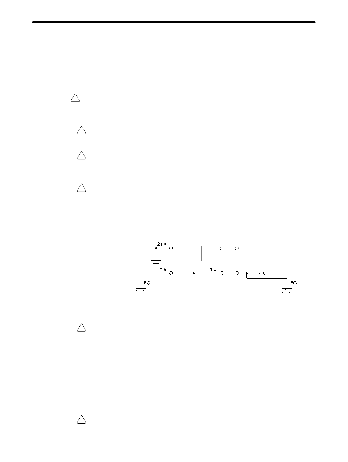
Caution When connecting a personal computer or other peripheral device to the CPM1A,
!
either ground the 0 V side of the CPM1A or do not ground at all. Depending on
the method of grounding, the 24-V power supply may short-circuit; do not
ground the 24-V side as shown in the following diagram.
Example: Connections where 24-V Power Supply Will Short-circuit
Non-isolated DC
power supply
CPM1A Peripheral device
4 Operating Environment Precautions
Caution Do not operate the control system in the following places:
!
• Locations subject to direct sunlight.
• Locations subject to temperatures or humidity outside the range specified in
the specifications.
• Locations subject to condensation as the result of severe changes in tempera-
ture.
• Locations subject to corrosive or flammable gases.
• Locations subject to dust (especially iron dust) or salts.
• Locations subject to exposure to water, oil, or chemicals.
• Locations subject to shock or vibration.
Caution Take appropriate and sufficient countermeasures when installing systems in the
!
following locations:
xvii

• Locations subject to static electricity or other forms of noise.
• Locations subject to strong electromagnetic fields.
• Locations subject to possible exposure to radioactivity.
• Locations close to power supplies.
Caution The operating environment of the PC System can have a large effect on the lon-
!
gevity and reliability of the system. Improper operating environments can lead to
malfunction, failure, and other unforeseeable problems with the PC System. Be
sure that the operating environment is within the specified conditions at installation and remains within the specified conditions during the life of the system.
5 Application Precautions
Observe the following precautions when using the PC System.
WARNING Always heed these precautions. Failure to abide by the following precautions
!
could lead to serious or possibly fatal injury.
• Always connect to a ground of 100 Ω or less when installing the Units. Not connecting to a ground of 100 Ω or less may result in electric shock.
• Always turn off the power supply to the PC before attempting any of the following. Not turning off the power supply may result in malfunction or electric
shock.
• Mounting or dismounting I/O Units, CPU Units, or any other Units.
• Assembling the Units.
• Connecting or wiring the cables.
• Connecting or disconnecting the connectors.
5Application Precautions
Caution Failure to abide by the following precautions could lead to faulty operation of the
!
PC or the system, or could damage the PC or PC Units. Always heed these precautions.
• Fail-safe measures must be taken by the customer to ensure safety in the
event of incorrect, missing, or abnormal signals caused by broken signal lines,
momentary power interruptions, or other causes.
• Construct a control circuit so that power supply for the I/O circuits does not
come ON before power supply for the Unit. If power supply for the I/O circuits
comes ON before power supply for the Unit, normal operation may be temporarily interrupted.
• If the operating mode is changed from RUN or MONITOR mode to PROGRAM
mode, with the IOM Hold Bit ON, the output will hold the most recent status. In
such a case, ensure that the external load does not exceed specifications. (If
operation is stopped because of an operation error (including FALS instructions), the values in the internal memory of the CPU Unit will be saved, but the
outputs will all turn OFF.)
• Always use the power supply voltage specified in the operation manuals. An
incorrect voltage may result in malfunction or burning.
• Take appropriate measures to ensure that the specified power with the rated
voltage and frequency is supplied. Be particularly careful in places where the
power supply is unstable. An incorrect power supply may result in malfunction.
• Install external breakers and take other safety measures against short-circuiting in external wiring. Insufficient safety measures against short-circuiting may
result in burning.
xviii

5Application Precautions
• Do not apply voltages to the Input Units in excess of the rated input voltage.
Excess voltages may result in burning.
• Do not apply voltages or connect loads to the Output Units in excess of the
maximum switching capacity. Excess voltage or loads may result in burning.
• Disconnect the functional ground terminal when performing withstand voltage
tests. Not disconnecting the functional ground terminal may result in burning.
• Install the Unit properly as specified in the operation manual. Improper installation of the Unit may result in malfunction.
• Be sure that all the mounting screws, terminal screws, and cable connector
screws are tightened to the torque specified in the relevant manuals. Incorrect
tightening torque may result in malfunction.
• With version-1 CPU Units, leave the label attached wiring in order to prevent
wiring cuttings from entering in the Unit.
• With pre-version-1 CPU Units, be sure to attach the supplied labels when wiring in order to prevent wiring cuttings from entering in the Unit.
• Remove the label after the completion of wiring to ensure proper heat dissipation. Leaving the label attached may result in malfunction.
• Use crimp terminals for wiring. Do not connect bare stranded wires directly to
terminals. Connection of bare stranded wires may result in burning.
• Double-check all the wiring before turning on the power supply. Incorrect wiring may result in burning.
• Be sure that the terminal blocks, expansion cables, and other items with locking devices are properly locked into place. Improper locking may result in malfunction.
• Check the user program for proper execution before actually running it on the
Unit. Not checking the program may result in an unexpected operation.
• Confirm that no adverse effect will occur in the system before attempting any of
the following. Not doing so may result in an unexpected operation.
• Changing the operating mode of the PC.
• Force-setting/force-resetting any bit in memory.
• Changing the present value of any word or any set value in memory.
• Resume operation only after transferring to the new CPU Unit the contents of
the DM and HR Areas required for resuming operation. Not doing so may result
in an unexpected operation.
• Do not pull on the cables or bend the cables beyond their natural limit. Doing
either of these may break the cables.
• Do not place objects on top of the cables. Doing so may break the cables.
• When replacing parts, be sure to confirm that the rating of a new part is correct.
Not doing so may result in malfunction or burning.
• Before touching the Unit, be sure to first touch a grounded metallic object in
order to discharge any static built-up. Not doing so may result in malfunction or
damage.
• Do not touch the Expansion I/O Unit Connecting Cable while the power is being supplied in order to prevent any malfunction due to static electricity.
• When using a thermocouple-input type Temperature Sensor Unit, observe the
following precautions:
• Do not remove the cold junction compensator attached at the time of deliv-
ery. If the cold junction compensator is removed the Unit will not be able to
measure temperatures correctly.
• Each of the input circuits is calibrated with the cold junction compensator
attached to the Unit. If the Unit is used with the cold junction compensator
from other Units, the Unit will not be able to measure temperatures correctly.
xix
• Do not touch the cold junction compensator. Doing so may result in incor-
rect temperature measurement.
Caution Always clear memory before beginning to program the CPM1A. Although
!
memory is cleared before the CPU Unit is shipped (except for bits with specific
functions), AR 1314, which turns ON when the internal capacitor cannot back up
memory, may have turned ON during shipment.
Caution If the CPM1A will be turned off for periods exceeding the data backup period of
!
the internal capacitor, design the system so that it will not be influenced if data in
the DM, HR, and CNT areas is cleared when power is turned off.
Caution Either switch the CPM1A to RUN or MONITOR mode, or turn off and on power to
!
the CPM1A after changing from a Programming Device any data that is backed
up in flash memory. This data includes the user program, read-only DM area
(DM 6144 to DM 6599), and the PC Setup (DM 6600 to DM 6655).
• The user program and memory area data in the CPM1A are backed up either
by an internal capacitor or in flash memory as shown in the following table.
Backup method Data
Internal capacitor Read/write DM area (DM 0000 to DM 0999, DM 1022, and
Flash memory User program
DM 1023)
Error log area (DM 1000 to DM 1021)
HR area (HR 00 to HR 19)
Counter area (CNT 000 to CNT 127)
Read-only DM area (DM 6144 to DM 6599)
PC Setup (DM 6600 to DM 6655)
5Application Precautions
Note 1. The IR, TR, LR, and timer areas are not normally backed up when power is
turned off and all contents will be cleared the next time power is turned on.
(The PC Setup setting in DM 6601 can be used to back up this data. Refer to
details on the PC Setup later in this manual for details.)
2. The bits in the AR and SR areas have special functions and are set according to these functions when power is turned on.
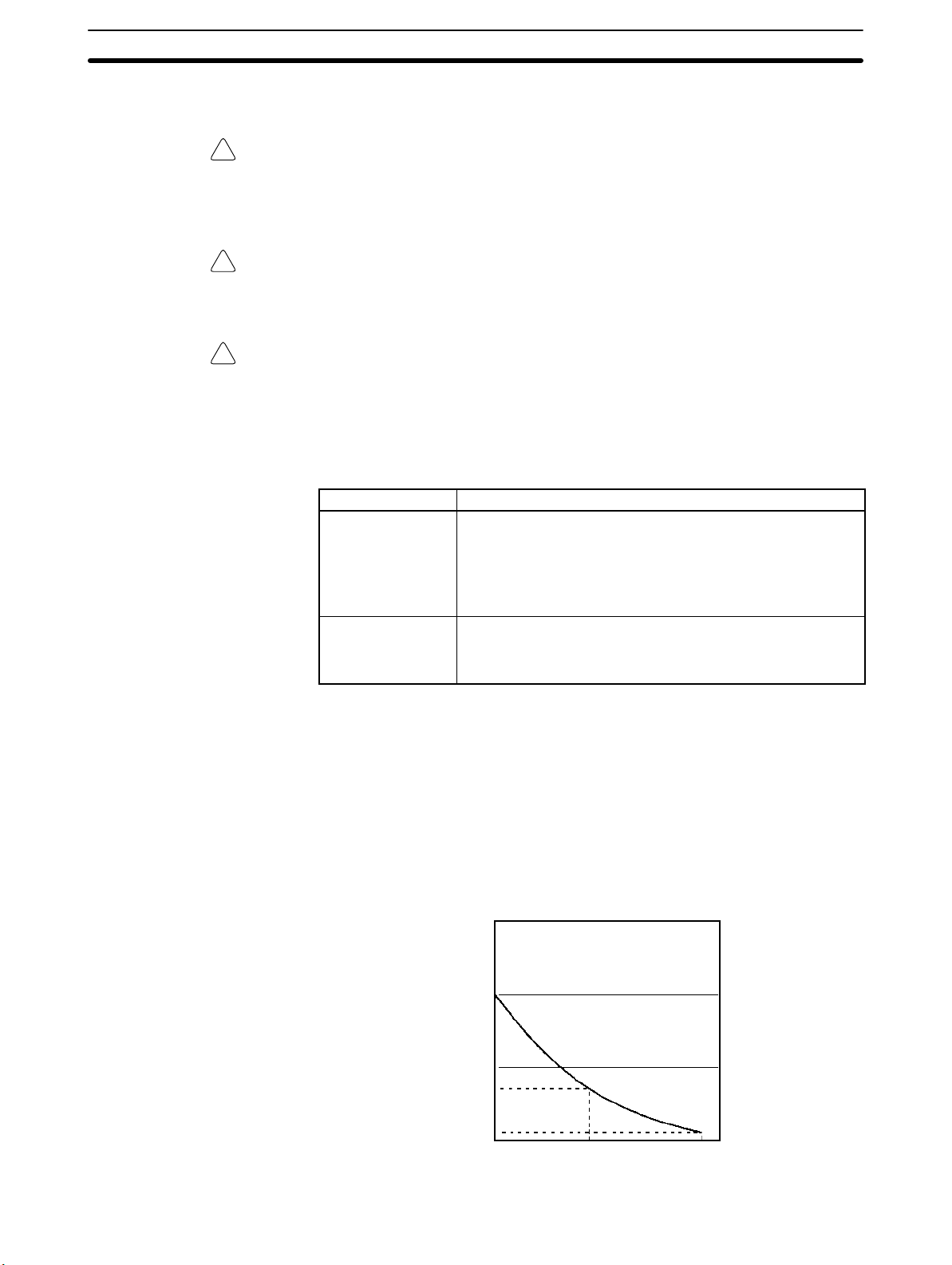
• The capacitor backup time depends on the ambient temperature, as shown in
the following graph. The backup time, however, assumes that the capacitor is
fully charged, which requires that power be supplied to the CPU Unit continuously for at least 15 minutes.
20
10
Backup time (days)
7
1
25 40 80
Ambient temperature (C)
xx

If the power remains off for a period exceeding the data backup period,
AR 1314 will turn ON to indicate that the capacitor can no longer back up data
and the data backed up by the capacitor will be cleared. AR 1314 will remain
ON unless it is turned OFF using I/O monitor operations, using memory clear
operations, or from the user program.
If desired, the PC Setup setting in DM 6604 can be set to create a fatal error
and thus stop the system when AR 1314 goes ON.
• The data stored in flash memory will not be lost even if power remains off for a
period exceeding the data backup period, because the data stored in flash
memory will be read to the CPU Unit when the CPM1A is turned on.
• If the power is turned off without changing the mode from PROGRAM mode to
RUN or MONITOR mode after having made changes in the data that is backed
up in flash memory, the changes will not be written to flash memory. If the power is then left off for more than 20 days (at 25C), the changes (i.e., the contents of the RAM) will be erased and the data values will become undefined.
6 EC Directives
6-1 Applicable Directives
• EMC Directives
• Low Voltage Directive
6EC Directives
6-2 Concepts
EMC Directives
OMRON devices that comply with EC Directives also conform to the related
EMC standards so that they can be more easily built into other devices or the
overall machine. The actual products have been checked for conformity to EMC
standards (see the following note). Whether the products conform to the standards in the system used by the customer, however, must be checked by the
customer.
EMC-related performance of the OMRON devices that comply with EC Directives will vary depending on the configuration, wiring, and other conditions of the
equipment or control panel on which the OMRON devices are installed. The customer must, therefore, perform the final check to confirm that devices and the
overall machine conform to EMC standards.
Note Applicable EMC (Electromagnetic Compatibility) standards are as follows:
EMS (Electromagnetic Susceptibility): EN61131-2
EMI (Electromagnetic Interference): EN61000-6-4
Low Voltage Directive
Always ensure that devices operating at voltages of 50 to 1,000 VAC or 75 to
1,500 VDC meet the required safety standards for the PC (EN61131-2).
6-3 Conformance to EC Directives
All CPM1A CPU Units with model numbers ending in “-V1” conform to EC directives.
The following restrictions apply to CPM1A CPU Units with model numbers not
ending in “-V1.”
• Relay Output Units and Transistor Output Units of CPU Units with DC power
supplies conform to EC Directives. Relay Output Units, however, conform to
EC Directives only when the output load power supply is outside the ranges
specified for the Low Voltage Directive (less than 75 VDC or less than 50 VAC).
• Relay Output Units and Transistor Output Units of CPM1A CPU Units with AC
power supplies do not conform to EC Directives.
(Radiated emission: 10-m regulations)
xxi

All Expansion I/O Units except for the CPM1A-20EDR conform to EC Directives.
To ensure that the machine or device in which the CPM1A PC is used complies
with EC Directives, the PC must be installed as follows:
1, 2, 3... 1. The CPM1A PC must be installed within a control panel.
2. Reinforced insulation or double insulation must be used for the DC power
supplies used for the PC and I/O power supplies.
3. CPM1A PCs complying with EC Directives also conform to the Common
Emission Standard (EN61000-6-4). Radiated emission characteristics
(10-m regulations) may vary depending on the configuration of the control
panel used, other devices connected to the control panel, wiring, and other
conditions. You must therefore confirm that the overall machine or equipment complies with EC Directives.
6-4 Relay Output Noise Reduction Methods
All CPM1A CPU Units with model numbers ending in “-V1” conform to the Common Emission Standards (EN61000-6-4) of the EMC Directives.
For CPM1A CPU Units with model numbers not ending in “-V1,” Relay Output
Units and Transistor Output Units of CPU Units with DC power supplies conform
to the Common Emission Standards (EN61000-6-4) of the EMC Directives.
Relay Output Units, however, conform to the Common Emission Standards
(EN61000-6-4) only when the output load power supply is outside the ranges
specified for the Low Voltage Directive (less than 75 VDC or less than 50 VAC).
6EC Directives
When a Unit is built into another device, however, it may not satisfy these standards due to noise generated by relay output switching. In such a case, a noise
filter must be connected to the load side or other appropriate countermeasures
must be provided external to the PC.
Countermeasures taken to satisfy the standards vary depending on the devices
on the load side, wiring, configuration of machines, etc. Following are examples
of countermeasures for reducing the generated noise.
Countermeasures
Refer to EN50081-2 for more details.
Countermeasures are not required if the frequency of load switching for the
whole system including the PC is less than 5 times per minute.
Countermeasures are required if the frequency of load switching for the whole
system including the PC is more than 5 times per minute.
Countermeasure Examples
When switching an inductive load, connect a surge protector, diodes, etc., in parallel with the load or contact. For detailed circuit examples, refer to the relevant
parts of this manual.
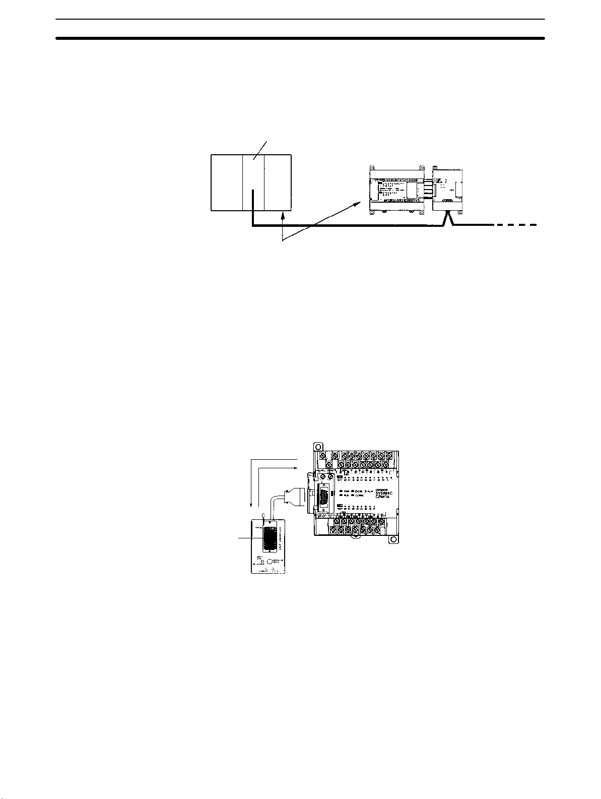
6-5 CPM1A-MAD01 Conformance to EMC Directives
xxii
Immunity testing conditions when using the current I/O of the CPM1A-MAD01
are as follows.
• Total accuracy: +10%/-1%
• Insert the following core in each line as shown below.
Recommended core: 2643-002402

Manufacturer: Fair Rite Products Corp.
7 Revised Specifications
The following table shows the changes that have been made in product specifications beginning with lots produced in January 1998 (December 1997 for some
models).
Item Previous specifications New specifications Relevant pages
Input indicator operation
when an error occurs
Memory holding operation
of built-in capacitor
The input indicators will
maintain the current status
and will not change with the
status of the input signal
when a memory error, no
END instruction error, or
system error occurs.
If the power remains OFF
for a period exceeding the
data backup period, the
capacitor will not be able to
back up data and the
status of the data backed
up by the capacitor
(Read/write DM area, Error
log area, HR area, and
Counter area) will become
unstable.
The input indicators will
change with the status of
the input signal when a
memory error, no END
instruction error, or system
error occurs.
If the power remains OFF
for a period exceeding the
data backup period,
AR 1314 will turn ON to
indicate that the capacitor
can no longer back up data
and the data backed up by
the capacitor (Read/write
DM area, Error log area,
HR area, and Counter
area) will be cleared. The
PC Setup setting in
DM 6604 can be set to
create a fatal error and thus
stop the system when
AR 1314 goes ON.
7Revised Specifications
Item 8., Input Indicators, on
page 33.
Pages xviii to xx under 5
Application Precautions.
Page 24 under 2-1-2
Characteristics.
See also information on the
PC Setup in the
CPM1/CPM1A/CPM2A/CPM2
C/SRM1(-V2) Programmable
Controllers Programming
Manual (W353).
xxiii

Item Relevant pagesNew specificationsPrevious specifications
spec ca o s
Online editing and changing
set values from the SSS
Communications
parameters for the
peripheral port
If unsupported addresses
are set in the program for
operands or for set values
for timers or counters from
the SSS during online
editing, the values will be
accepted, but a memory
error will occur in
MONITOR or RUN mode.
Communications are not
possible if unsupported
settings are made for the
peripheral port’s
communications
parameters.
If unsupported addresses
are set in the program for
operands or for set values
for timers or counters from
the SSS during online
editing, error messages will
be displayed and the
values will not be accepted.
Communications are
possible using the following
parameters if unsupported
settings are made for the
peripheral port’s
communications
parameters.
Mode: Host Link
Standard format
1 start bit
7-bit data
Even parity
2 stop bits
9,600 bps baud
Transmission delay: None
Unit number: 0
7Revised Specifications
4-1-2 CPM1A Restrictions and
Precautions
See information on the PC
Setup in the
CPM1/CPM1A/CPM2A/CPM2
C/SRM1(-V2) Programmable
Controllers Programming
Manual (W353).
Item Previous specifications New specifications Relevant pages
Support for UM Area
allocation function
The following specifications have changed in products manufactured since October 2000.
The UM Area allocation
function is not supported.
As a result, a memory error
will be displayed if the I/O
comment area is set
(although no actual
memory error has
occurred).
CX-Programmer can be
used to set the I/O
comment area in the CPU
Unit, and I/O comments
can be set together with
programs.
See information on UM Area
allocation in the
WS02-CXPC1-EV3
CX-Programmer Operation
Manual (W414) and the
WS02-CXPC1-E-V4
CX-Programmer Operation
Manual (W425).
The following table shows the changes that have been made in product specifications beginning with the introduction of version-1 Units in May 2001 (April
2001 for some models).
Item New specifications (V1 models)
EC Directives All products with model numbers ending in “-V1”
conform to EC Directives.
Model numbers “-V1” was added to the end of the model
numbers.
External appearance
Output
specifications
Terminal blocks The functional earth terminal was eliminated
External dimensions The depth of CPU Units with AC power supplies
Relay outputs The mechanical life of output relays was
Transistor
outputs
The arrangement of input, output, and operation
indicators was changed.
The shape of the I/O connector was changed.
increased from 10 to 20 million operations.
The fuse was eliminated for both sourcing and
sinking outputs.
(i.e., converted to an NC terminal) on CPU Units
with AC power supplies.
was decreased from 85 mm to 70 mm.
xxiv

In this manual, version-1 CPU Units are referred to as V1 CPU Units and the
previous CPU Units are referred to as pre-V1 CPU Units.
Unless otherwise specified, “CPM1A” refers to both V1 and pre-V1 CPU Units.
7Revised Specifications
xxv

SECTION 1
Introduction
This section describes the CPM1A’s special features and functions and shows the possible system configurations. Refer to the
Programming Manual (W353) for details on programming actual operation.
1-1 CPM1A Features and Functions 2. . . . . . . . . . . . . . . . . . . . . . . . . . . . . . . . . . . . . . . . . . . . .
1-1-1 CPM1A Features 2. . . . . . . . . . . . . . . . . . . . . . . . . . . . . . . . . . . . . . . . . . . . . . . . . .
1-1-2 I/O Terminal and IR Bit Allocation 5. . . . . . . . . . . . . . . . . . . . . . . . . . . . . . . . . . . .
1-1-3 CPM1A Functions 5. . . . . . . . . . . . . . . . . . . . . . . . . . . . . . . . . . . . . . . . . . . . . . . . .
1-2 System Configuration 10. . . . . . . . . . . . . . . . . . . . . . . . . . . . . . . . . . . . . . . . . . . . . . . . . . . . . .
1-2-1 CPU Unit and Expansion I/O Unit Configuration 10. . . . . . . . . . . . . . . . . . . . . . . . .
1-2-2 CPU Unit and Expansion Unit 12. . . . . . . . . . . . . . . . . . . . . . . . . . . . . . . . . . . . . . . .
1-2-3 Host Link Communications 14. . . . . . . . . . . . . . . . . . . . . . . . . . . . . . . . . . . . . . . . . .
1-2-4 One-to-one PC Link Communications 16. . . . . . . . . . . . . . . . . . . . . . . . . . . . . . . . .
1-2-5 One-to-one NT Link Communications 17. . . . . . . . . . . . . . . . . . . . . . . . . . . . . . . . .
1-2-6 CompoBus/S I/O Link Connections 17. . . . . . . . . . . . . . . . . . . . . . . . . . . . . . . . . . .
1-2-7 DeviceNet I/O Link Connections 18. . . . . . . . . . . . . . . . . . . . . . . . . . . . . . . . . . . . .
1-2-8 Peripheral Device Connections 18. . . . . . . . . . . . . . . . . . . . . . . . . . . . . . . . . . . . . . .
1

CPM1A Features and Functions Section 1-1
1-1 CPM1A Features and Functions
1-1-1 CPM1A Features
One-piece Construction The CPM1A CPU Units feature a one-piece construction including 10, 20, 30, or
40 built-in I/O terminals. The following three model groups are available: relay
output models, sinking transistor output models, and sourcing transistor output
models.
CPU Units with 10 I/O Points
CPM1A-10CD--V1 CPM1A-10CD-
CPU Units with 30 I/O Points
CPM1A-30CD--V1 CPM1A-30CD-
CPU Units with 40 I/O Points
CPM1A-40CD--V1 CPM1A-40CD-
CPU Units with 20 I/O Points
CPM1A-20CD--V1 CPM1A-20CD-
Extra I/O Capacity Up to three Expansion I/O Units can be connected to a CPM1A-30CD-(-V1)
or CPM1A-40CD-(-V1) CPU Unit to add an extra 8 or 20 I/O points for each,
for a maximum of up to 100 I/O points.
Input Filter Function The CPM1A is equipped with a filter function to prevent incorrect operation
caused by chatter or noise in the input signal. The user can select an input time
constant of 1 ms, 2 ms, 4 ms, 8 ms, 16 ms, 32 ms, 64 ms, or 128 ms.
Low-maintenance Design Flash memory provides memory backup without a battery.
Input Interrupts The CPM1A-10CD-(-V1) CPU Units can handle 2 interrupt inputs; the
CPM1A-20CD-(-V1), CPM1A-30CD-(-V1), and CPM1A-40CD-
(-V1) CPU Units can handle 4 interrupt inputs. In addition to normal input interrupts, the CPM1A has a counter mode that counts high-speed input signals and
triggers interrupts at fixed count multiples.
Quick-response Inputs Quick-response inputs can detect input signals with a pulse width as short as
0.2 ms regardless of their timing during the PC cycle. Quick-response inputs
and interrupt inputs use the same input terminals.
2

CPM1A Features and Functions Section 1-1
Interval Timer CPM1A PCs have a high-speed interval timer which can be set from 0.5 ms to
319,968 ms. The timer can be set to trigger a single interrupt (one-shot mode) or
repeat scheduled interrupts (scheduled interrupt mode).
High-speed Counter CPM1A PCs have a high-speed counter that can be used in incremental mode
or up/down mode. The high-speed counter can be combined with input interrupts to perform target value control or zone comparison control that isn’t
affected by the PC’s cycle time.
Pulse Output Function The CPM1A transistor output models have an output function capable of output-
ting a pulse of 20 Hz to 2 kHz (single-phase output).
Analog Setting Function The CPM1A PCs have 2 analog volume controls that can be used to make
manual analog settings.
Analog I/O Units
Up to 3 Analog I/O Units can be connected to provide analog inputs and outputs.
Each Unit provides 2 analog inputs and 1 analog output, so a maximum of 6 analog inputs and 3 analog outputs can be achieved by connecting 3 Analog I/O
Units.
Unit Analog inputs Analog outputs
CPM1A-MAD01 Signal range: 0 to 10 V, 1 to 5 V, or
4 to 20 mA, Resolution of 1/256
The open-circuit detection function
can be used with the 1 to 5 VDC
and 4 to 20 mA settings.
CPM1A-MAD11 Signal range: 0 to V 5, 0 to 10 V, 1
to 5 V, –10 to 10 V, 0 to 20 mA, or 4
to 20 mA, Resolution of 1/6,000
The open-circuit detection function
can be used with the 1 to 5 VDC
and 4 to 20 mA settings.
Signal range: 0 to 10 V,
–10 to 10 V, or 4 to
20 mA,
Resolution of 1/256
Signal range: 0 to 10 V, 1
to 5 V, –10 to 10 V, 0 to
20 mA, or 4 to 20 mA,
Resolution of 1/6,000
Temperature Sensor
Units
A Temperature Sensor Unit can be connected to provide up to 6 inputs for temperature input from sensors, such as thermocouples or platinum resistance
thermometers.
Temperature Sensor Unit Functions
Thermocouple input (CPM1A-TS001/002; 2/4 input points):
K: –200° to 1,300°C (–300° to 2,300°F)
0.0° to 500.0°C (0.0° to 900.0°F)
J: –100° to 850°C (–100° to 1,500°F)
0.0° to 400.0°C (0.0° to 750.0°F)
Platinum resistance thermometer input (CPM1A-TS101/102; 2/4 input points):
Pt100: –200.0° to 650.0°C (–300.0° to 1,200.0°F)
JPt100: –200.0° to 650.0°C (–300.0° to 1,200.0°F)
Host Link Communications The CPM1A PCs are compatible with the Host Link, which allows communica-
tions with personal computers. The CPM1A using the Host Link can also communicate with Programmable Terminal using host link commands.
An RS-232C Adapter is used for 1:1 communications and an RS-422 Adapter is
used for 1:N communications.
One-to-one PC Link A data link can be created with a data area in another CPM1A, CQM1, CPM1,
SRM1 or C200HS or C200HX/HG/HE PC. An RS-232C Adapter is used to make
the 1:1 connection.
NT Link Communications High-speed operations can be achieved by providing a direct access by con-
necting the CPM1A to the OMRON Programmable Terminal through the NT Link
Interface. An RS-232C Adapter is used for this connection.
CompoBus/S I/O Link
Units
Up to 3 CompoBus/S I/O Link Units can be connected to make the CPM1A a
Slave Device in a CompoBus/S Network. The I/O Link Unit has 8 input bits (internal) and 8 output bits (internal).
3
CPM1A Features and Functions Section 1-1
The CompoBus/S Network provides distributed CPU control based on a “PC +
compact PC” configuration, which is an improvement on the earlier distributed
I/O control based on a “PC + remote I/O” configuration. The distributed CPU
control makes equipment modular, so designs can be standardized, special
needs can be addressed, and modules can be replaced easily in the event of a
breakdown.
CompoBus/S Master Unit
Master PC
DeviceNet I/O Link Units DeviceNet I/O Link Units can be connected to enable using the CPM1A as a De-
viceNet slave. Up to 32 internal input and 32 internal outputs points are supported for each Unit, and up to 3 Units can connected. DeviceNet application
allows networks to be constructed including devices from other manufacturers.
(or SRM1 CompoBus/S Master Control Unit)
CPM1A (Slave) CompoBus/S I/O Link Unit
CompoBus/S
Distributed CPU control
Standard Peripheral Devices The CPM1A uses the same Programming Consoles and SYSMAC Support
Software (SSS) as the C200H/HS, C200HX/HG/HE, CPM1, SRM1, and CQM1
PCs.
Programming is Possible
Using the PT
Expansion Memory Unit
Programming operation is possible through the PT screen by using an OMRON
PT that has a built-in Programming Console function.
The CPM1-EMU01-V1 Expansion Memory Unit is a program loader for smallsize or micro PLCs. Using the CPM1-EMU01-V1, simple on-site transfer of user
programs and data memory is possible with PLCs.
Uploading
Downloading
EEPROM
SYSMAC
4
yp
CPM1A Features and Functions Section 1-1
1-1-2 I/O Terminal and IR Bit Allocation
The following table shows which IR bits are allocated to the I/O terminals on the
CPM1A’s CPU Units and Expansion I/O Unit.
CPU Units
No. of I/O terminals on the CPU
Unit
Power supply AC DC AC DC AC DC AC DC
Model
No.
Relay
outputs
Sinking
transistor
outputs
Sourcing
transistor
outputs
CPU
Inputs 6 points:
Unit
terminals
Outputs 4 points:
10 20 30 40
CPM1A10CDR-A(-V1)
CPM1A10CDT-A(-V1)
CPM1A10CDT1-A(-V1)
00000 to 00005
01000 to 01003
CPM1A10CDR-D(-V1)
CPM1A10CDT-D(-V1)
CPM1A10CDT1-D(-V1)
CPM1A20CDR-A(-V1)
CPM1A20CDT-A(-V1)
CPM1A20CDT1-A(-V1)
12 points:
00000 to 00011
8 points:
01000 to 01007
CPM1A20CDR-D(-V1)
CPM1A20CDT-D(-V1)
CPM1A20CDT1-D(-V1)
CPM1A30CDR-A(-V1)
CPM1A30CDT-A(-V1)
CPM1A30CDT1-A(-V1)
18 points:
00000 to 00011
00100 to 00105
12 points:
01000 to 01007
01100 to 01103
CPM1A30CDR-D(-V1)
CPM1A30CDT-D(-V1)
CPM1A30CDT1-D(-V1)
CPM1A40CDR-A(-V1)
CPM1A40CDT-A(-V1)
CPM1A40CDT1-A(-V1)
24 points:
00000 to 00011
00100 to 00111
16 points:
01000 to 01007
01100 to 01107
CPM1A40CDR-D(-V1)
CPM1A40CDT-D(-V1)
CPM1A40CDT1-D(-V1)
Expansion I/O Units
Unit I/O Relay output
Sinking outputs Sourcing outputs
20 I/O
points
12 inputs
8 outputs
CPM1A-20EDR
CPM1A-20EDR1
CPM1A-20EDT CPM1A-20EDT1
8 inputs 8 inputs CPM1A-8ED
8 outputs 8 outputs CPM1A-8ER CPM1A-8ET CPM1A-8ET1
Transistor output
1-1-3 CPM1A Functions
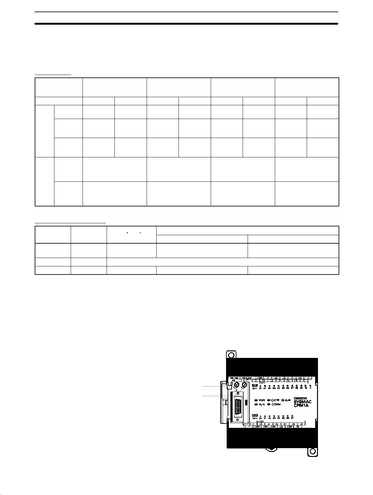
Analog Setting Function CPM1A PCs have 2 variable-resistor adjustment knobs used to control analog
timer and counter settings manually. When one of the adjustments is turned, the
content of the corresponding IR word is set automatically between 0 and 200
(BCD).
Turn the adjustment knob with a Phillips screwdriver.
Analog adjustment 0
Analog adjustment 1
24 VDC 0.2 A
OUT PUT
5
CPM1A Features and Functions Section 1-1
The following table shows which IR words are allocated to the analog adjustments on the CPM1A’s CPU Unit.
Control Corresponding IR word Setting range (BCD)
Analog adjustment 0 IR 250
Analog adjustment 1 IR 251
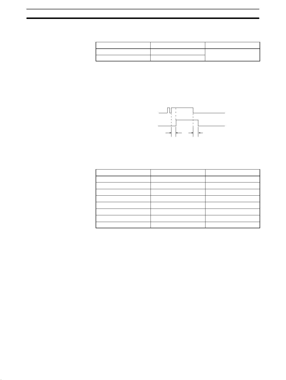
Input Filter Function The input time constant for the CPM1A’s external inputs can be set to 1, 2, 4, 8,
16, 32, 64, or 128 ms. Increasing the input time constant can reduce the effects
of chatter or noise in the input signal.
Input from an input device
such as a limit switch
Input bit status
t
0000 to 0200
t
Input time constant
With the CPM1A, actual response time for each set input time constant for word
000 is different from that for word 001 or later.
Set value Word 000 Word 001 or later
1 ms 1 to 1.5 ms 0.1 to 0.3 ms
2 ms 2 to 2.5 ms 0.7 to 1.5 ms
4 ms 4 to 4.5 ms 1.5 to 2.5 ms
8 ms 8 to 8.5 ms 3 to 4.5 ms
16 ms 16 to 16.5 ms 6 to 9 ms
32 ms 32 to 32.5 ms 12 to 18 ms
64 ms 64 to 64.5 ms 24 to 35 ms
128 ms 128 to 128.5 ms 50 to 70 ms
The input response time of the CPM1A is obtained with the following:
2 ms max. (hardware performance) + input time constant (see above table)
+ cycle time
Input Interrupts The CPM1A-10CDR-(-V1)/10CDT-D(-V1)/10CDT1-D(-V1) PCs have 2 inter-
rupt input terminals and the CPM1A-20CDR-(-V1)/20CDT-
D(-V1)/20CDT1-D(-V1), CPM1A-30CDR-(-V1)/ 30CDT-D/30CDT1-D(-V1),
and CPM1A-40CDR-(-V1)/40CDT-D(-V1)/40CDT1-D(-V1) PCs have 4 inter-
rupt input terminals. There are two modes for input interrupts: input interrupt
mode and counter mode.
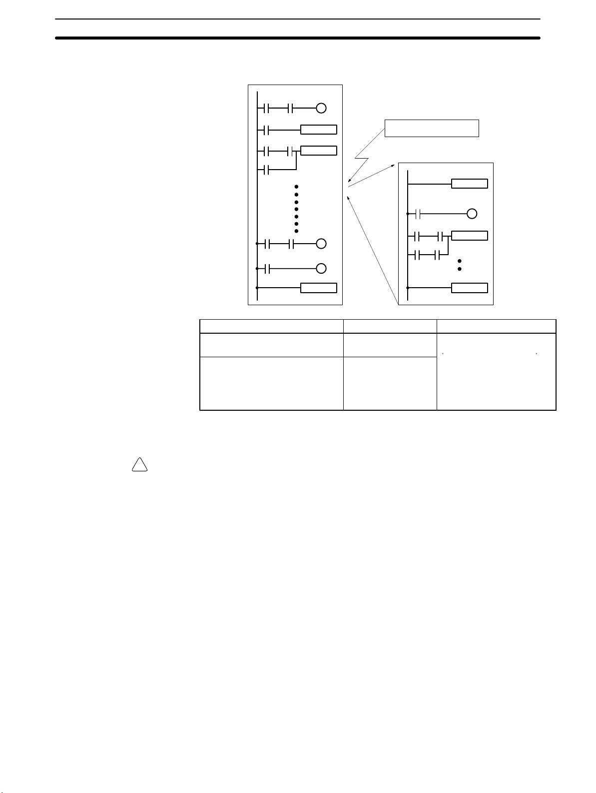
1, 2, 3... 1. When an interrupt occurs in Input Interrupt Mode, the main program is inter-
rupted and the interrupt program is executed immediately, regardless of the
cycle time.
2. In Counter Mode, external input signals are counted at high speed (up to
1 kHz) and an interrupt is generated each time the count reaches the set
value. When an interrupt occurs, the main program is interrupted and the
interrupt program is executed. The set value can be set from 0 to 65,535.
6
()
CPM1A Features and Functions Section 1-1
The following diagram shows the program execution when an interrupt occurs.
Main program
MOV
ADD
END
PC model Input bits Response time
CPM1A-10CDR-(-V1)/
10CDT-D(-V1)/10CDT1-D(-V1)
CPM1A-20CDR-(-V1)/
20CDT-D(-V1)/20CDT1-D(-V1)/
30CDR-(-V1)/30CDT-D(-V1)/
30CDT1-D(-V1)/40CDR-(-V1)/
40CDT-D(-V1)/40CDT1-D(-V1)
Input interrupt
Interrupt program
IR 00003 to IR 00004
IR 00003 to IR 00006
SBN00
MOV
RET
0.3 ms
(1 kHz in Counter Mode)
Note When not using as interrupt input terminals, the input bits IR 00003 to IR 00006
can be used as normal input terminals.
Caution Although IORF(97) can be used in interrupt subroutines, you must be careful of
!
the interval between IORF(97) executions. If IORF(97) is executed too frequently, a fatal system error may occur (FALS 9F), stopping operation. The interval
between executions of IORF(97) should be at least 1.3 ms + total execution time
of the interrupt subroutine.
7

CPM1A Features and Functions Section 1-1
Quick-response Inputs The CPM1A-10CDR-(-V1)/10CDT-D(-V1)/10CDT1-D(-V1) PCs have 2
quick-response input terminals and the CPM1A-20CDR-(-V1)/20CDT-
D/20CDT1-D(-V1), CPM1A-30CDR-(-V1)/30CDT-D(-V1)/30CDT1-D(-V1)
and CPM1A-40CDR-(-V1)/40CDT-D(-V1)/40CDT1-D(-V1) PCs have 4
quick-response input terminals. (The same terminals are used for quick-response inputs and interrupt inputs.)
Quick-response inputs have an internal buffer, so input signals shorter than one
cycle can be detected.
Interval Timer Function
(Scheduled Interrupts)
Input signal
(00003)
IR 00003
Overseeing
processes
Program
execution
One cycle
I/O
refreshing
Overseeing
processes
Program
execution
I/O
refreshing
PC model Input bits Min. input pulse
width
CPM1A-10CDR-(-V1)/
IR 00003 to IR 00004
0.2 ms
10CDT-D(-V1)/10CDT1-D(-V1)
CPM1A-20CDR-(-V1)/
IR 00003 to IR 00006
20CDT-D(-V1)/20CDT1-D(-V1)/
30CDR-(-V1)/30CDT-D(-V1)/
30CDT1-D(-V1)/40CDR-(-V1)/
40CDT-D(-V1)/40CDT1-D(-V1)
CPM1A PCs are equipped with an interval timer which can be set from 0.5 ms to
319,968 ms in units of 0.1 ms. The timer can be set to trigger a single interrupt
(one-shot mode) or to trigger scheduled interrupts (scheduled interrupt mode).
Main program
MOV
ADD
END
Interval timer time-out
Interrupt program
SBN00
MOV
RET
Mode Function
One-shot Generates a single interrupt the first time that the timer times
out.
Scheduled interrupt Generates an interrupt each time that the timer times out.
Pulse Output Function Since the CPM1A with transistor output has a pulse output function capable of
outputting a pulse of 20 Hz to 2kHz (single-phase output), a stepping motor can
be controlled by the CPU Unit alone.
8

CPM1A Features and Functions Section 1-1
The pulse output can be set to either the continuous mode, under which the output can be stopped by an instruction, or the single mode, under which the output
can be stopped by the preset pulse rate (1 to 16,777,215).
Stepping motor
Pulse output
(single-phase output)
Stepping motor
Motor
controller
CW/CCW control output
Control input
High-speed Counter CPM1A PCs have a high-speed counter that can be used in incremental mode
or up/down mode. The high-speed counter can be combined with input interrupts to perform target value control or zone comparison control that isn’t
affected by the PC’s cycle time.
00000
00001
Count input
Reset input
00002
Solenoid
Sensor Rotary encoder
Motor
controller
9

System Configuration
Section 1-2
Mode Input functions Input method Count
frequency
Up/Down 00000: A-phase input
00001: B-phase input
00002: Z-phase input
Incremental 00000: Count input
00001: See note.
00002: Reset input
Phase-difference,
4× inputs
Individual inputs 5.0 kHz 0
2.5 kHz –32767
Count
range
to
32767
to
65535
Target value control:
Up to 16 target values and interrupt
subroutine numbers can be
registered.
Zone comparison control:
Up to 8 sets of upper limit values,
lower limit values, and interrupt
subroutine numbers can be
registered.
Note In incremental mode, this input (00001) can be used as an regular input.
1-2 System Configuration
1-2-1 CPU Unit and Expansion I/O Unit Configuration
CPM1A CPU Units
10 I/O points
CPM1A-10CDR-(-V1)
CPM1A-10CDT-(-V1)
CPM1A-10CDT1-(-V1)
Control methods
20 I/O points
CPM1A-20CDR-(-V1)
CPM1A-20CDT-(-V1)
CPM1A-20CDT1-(-V1)
30 I/O points
CPM1A-30CDR-(-V1)
CPM1A-30CDT-(-V1)
CPM1A-30CDT1-(-V1)
40 I/O points
CPM1A-40CDR-(-V1)
CPM1A-40CDT-(-V1)
CPM1A-40CDT1-(-V1)
Not possible to add Expansion I/O Units
or Expansion Units.
Expansion I/O Units/Expansion Units
10

p
p
t
yp
p
p
p
p
p
p
p
p
p
p
t
yp
p
p
p
p
p
p
p
p
System Configuration
V1 CPM1A CPU Units
10 I/O points 20 I/O points 30 I/O points 40 I/O points
Section 1-2
Number
of I/O
erminals
10 6 points 4 points
20 12 points 8 points
30 18 points 12 points
40 24 points 16 points
Inputs Outputs Power
supply
AC CPM1A-10CDR-A-V1 CPM1A-10CDT-A-V1 CPM1A-10CDT1-A-V1
DC CPM1A-10CDR-D-V1 CPM1A-10CDT-D-V1 CPM1A-10CDT1-D-V1
AC CPM1A-20CDR-A-V1 CPM1A-20CDT-A-V1 CPM1A-20CDT1-A-V1
DC CPM1A-20CDR-D-V1 CPM1A-20CDT-D-V1 CPM1A-20CDT1-D-V1
AC CPM1A-30CDR-A-V1 CPM1A-30CDT-A-V1 CPM1A-30CDT1-A-V1
DC CPM1A-30CDR-D-V1 CPM1A-30CDT-D-V1 CPM1A-30CDT1-D-V1
AC CPM1A-40CDR-A-V1 CPM1A-40CDT-A-V1 CPM1A-40CDT1-A-V1
DC CPM1A-40CDR-D-V1 CPM1A-40CDT-D-V1 CPM1A-40CDT1-D-V1
Relay outputs
Model number
Transistor outputs
Sinking outputs Sourcing outputs
Pre-V1 CPM1A CPU Units
10 I/O points 20 I/O points 30 I/O points 40 I/O points
Number of
I/O
erminals
10 6 points 4 points
20 12 points 8 points
30 18 points 12 points
40 24 points 16 points
Inputs Outputs Power
supply
AC CPM1A-10CDR-A CPM1A-10CDT-A CPM1A-10CDT1-A
DC CPM1A-10CDR-D CPM1A-10CDT-D CPM1A-10CDT1-D
AC CPM1A-20CDR-A CPM1A-20CDT-A CPM1A-20CDT1-A
DC CPM1A-20CDR-D CPM1A-20CDT-D CPM1A-20CDT1-D
AC CPM1A-30CDR-A CPM1A-30CDT-A CPM1A-30CDT1-A
DC CPM1A-30CDR-D CPM1A-30CDT-D CPM1A-30CDT1-D
AC CPM1A-40CDR-A CPM1A-40CDT-A CPM1A-40CDT1-A
DC CPM1A-40CDR-D CPM1A-40CDT-D CPM1A-40CDT1-D
Relay outputs
Model number
Transistor outputs
Sinking outputs Sourcing outputs
11

System Configuration
1-2-2 CPU Unit and Expansion Unit
Up to 3 Expansion I/O Units or Expansion Units can be connected to a CPU Unit
with 30 or 40 I/O points.
There are three types of Expansion Units available: Analog I/O Units, Temperature Sensor Units, the CompoBus/S I/O Link Unit, and the DeviceNet I/O Link
Unit.
Section 1-2
Expansion Connector
Expansion I/O Connecting Cable
Expansion I/O Unit: Analog I/O Unit,
Temperature Sensor Unit, CompoBus/S I/O Link Unit, or DeviceNet I/O
Link Unit
A PC with 100 I/O points (the maximum) can be assembled by connecting three
Expansion I/O Units.
CPM1A-40CD-
(24 inputs, 16 outputs)
× 1 Unit + × 3 Units = 60 inputs, 40 outputs
CPM1A-20EDR1
(12 inputs, 8 outputs)
A PC with 6 analog inputs and 3 analog outputs (the maximum) can be assembled by connecting three Analog I/O Units.
A PC with up to 6 temperature inputs for input from thermocouples or platinum
resistance thermometers can be assembled by connecting Temperature Sensor
Units.
CompoBus/S I/O Link Units (Slave Units) can be connected to a CPU Unit. I/O
data (8 inputs and 8 outputs) is transferred between the CPU Unit and the area
allocated to the CompoBus/S Slave. (The I/O data exchanged with the Slave is
internal data; there are no external input or output terminals.)
Expansion I/O Units
12
Up to three DeviceNet I/O Link Units can be connected to a CPU Unit. Each DeviceNet I/O Link Unit enables using the CPM1A as a DeviceNet slave with 32
input and 32 output points.
Note Different types of Expansion Units can be connected at the same time. For ex-
ample, an Expansion I/O Unit, Analog I/O Unit, and CompoBus/S I/O Link Unit,
or an Expansion I/O Unit, Analog I/O Unit, and Temperature Sensor Unit can be
connected to the CPU Unit.
8-point Input Unit 8-point Output Unit20-point I/O Unit

p
12 inputs
p
Se so U
pu s
System Configuration
Section 1-2
Unit Max. number
of Units
20 I/O points 3 Units max.
12 inputs
8 outputs
8 inputs 24 VDC --- CPM1A-8ED
8 outputs
(See note.)
Inputs Outputs Model
24 VDC Relays CPM1A-20EDR1
24 VDC Sinking transistors CPM1A-20EDT
24 VDC Sourcing transistors CPM1A-20EDT1
--- Relays CPM1A-8ER
--- Sinking Transistors CPM1A-8ET
--- Sourcing Transistors CPM1A-8ET1
Expansion Units
CPM1A-MAD01
Analog I/O Unit
CompoBus/S I/O
Link Unit
CPM1A-MAD11
Analog I/O Unit
DeviceNet I/O
Link Unit
Temperature Sensor Unit
Unit Max. number
Analog I/O Unit
2 analog inputs (2 words)
1 analog output (1 word)
Temperature
Sensor Unit
CompoBus/S I/O Link Unit
8 inputs and 8 outputs
DeviceNet I/O Link Unit
32 inputs and 32 outputs
Thermocouple
inputs
Platinum
resistance
thermometer
inputs
Inputs Outputs Model
of Units
3 Units max.
(See note.)
3 Units max.
(See note.)
1 Unit max. 4 inputs (K, J) CPM1A-TS002
3 Units max.
(See note.)
1 Unit max. 4 inputs (Pt100, JPt100) CPM1A-TS102
3 Units max.
(See note.)
3 Units max.
(See note.)
2 analog inputs 1 analog output CPM1A-MAD01
CPM1A-MAD11
2 inputs (K, J)
2 inputs (Pt100, JPt100) CPM1A-TS101
8 bits
(Inputs from the Master.)
32 bits
(Inputs from the Master.)
---
8 bits
(Outputs to the Master.)
32 bits
(Outputs to the Master.)
CPM1A-TS001
CPM1A-SRT21
CPM1A-DRT21
Note Only one CPM1A-TS002/TS102 Temperature Sensor Unit can be connected to
the CPU Unit. If a CPM1A-TS002/102 is connected to the CPU Unit, only one
additional Expansion Unit (other than a CPM1A-TS002/102) or one Expansion
I/O Unit can be connected to the CPU Unit.
13
System Configuration
Section 1-2
1-2-3 Host Link Communications
Host Link communications which allows up to 32 OMRON PCs to be controlled
from a host computer. The computer-PC connections can be made connectors
such as RS-232C and RS-422 Adapters.
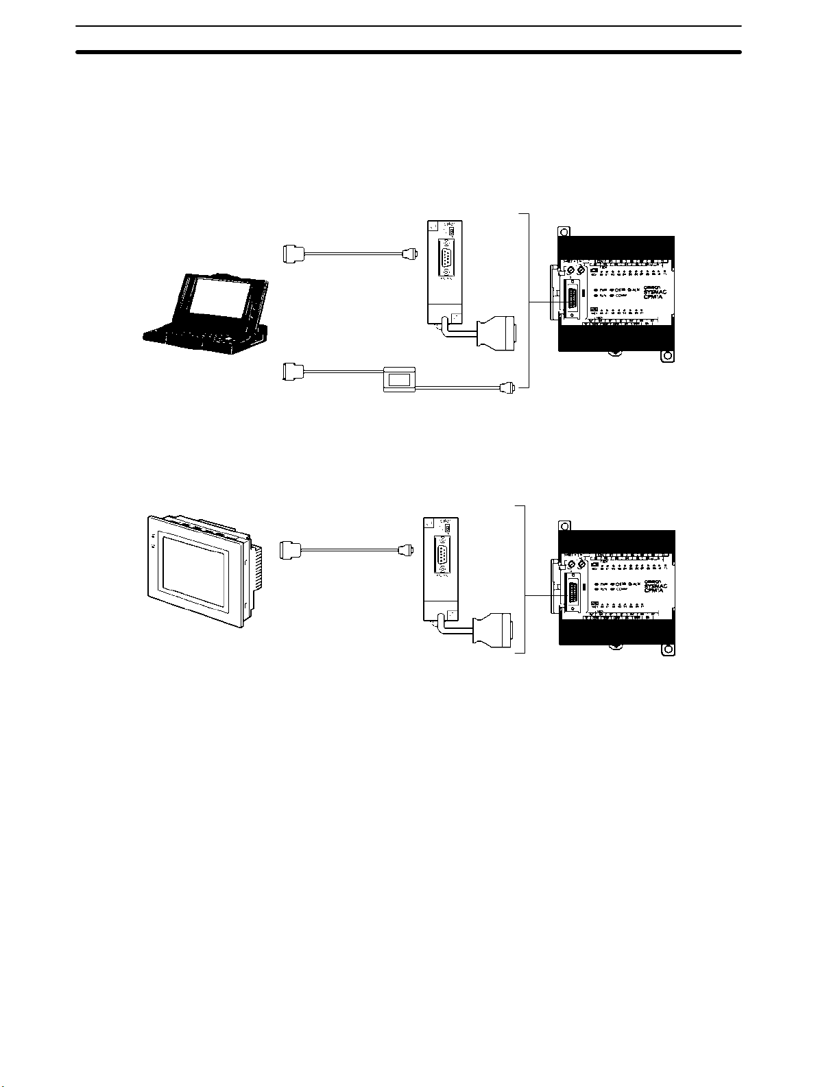
One-to-one Communications The following diagram shows the possible methods for a 1:1 connection
between a CPM1A and an IBM PC/AT or compatible computer.
IBM PC/AT or
compatible
Connecting to a
Programmable Terminal
OMRON Programmable Terminal
RS-232C Adapter
RS-232C Cable
XW2Z-200T (2 m)
XW2Z-500T (5 m)
CQM1-CIF02
CPM1A CPU Unit
The following diagram shows the possible methods for a connection between a
CPM1A PC and an OMRON Programmable Terminal (a operator interface
device).
RS-232C Adapter
RS-232C Cable
CPM1A CPU Unit
14

pp p
System Configuration
Section 1-2
One-to-N Communications The following diagram shows how to connect up to 32 CPM1A PCs to an IBM
PC/AT or compatible computer.
IBM PC/AT or compatible
3G2A9-AL004-E
Link Adapter
RS-232C Cable
RS-422 Cable
Adapters
CPM1A CPU UnitsRS-422
OMRON CPM1A PCs
The maximum cable length of RS-422 should be 500 m.
(32 PCs max.)
Adapters and Cables The following table lists some of the Adapters and Cables used in Host Link com-
munications.
Name Usage Model number
RS-232C Adapter
RS-422 Adapter
Connecting Cables Used to connect IBM PC/AT or
Link Adapter Converts between the RS-232C and
Converts to peripheral port-level
communications.
compatible computers.
(Cable length: 3.3 m)
RS-422 formats.
CPM1-CIF01
CPM1-CIF11
CQM1-CIF02
3G2A9-AL004-E
15

System Configuration
1-2-4 One-to-one PC Link Communications
A data link can be created with a data area in another CPM1A, CQM1, CPM1,
CPM2A, CPM2C, SRM1(-V2) or C200HS PC or a C200HX/HG/HE PC. An
RS-232C Adapter must be used to make the 1:1 connection.
CPM1A CPU UnitsRS-232C Adapters
RS-232C Cable
Section 1-2
CQM1 CPM1 + RS-232C Adapter
C200HS/C200HX/HG/HE
Name Usage Model number
RS-232C Adapter Converts to the Peripheral Port format. CPM1-CIF01
16

System Configuration
1-2-5 One-to-one NT Link Communications
Using the NT Link, the CPM1A PC can connected to the Programmable Terminal (NT Link Interface) through an RS-232C Adapter.
Section 1-2
OMRON Programmable Terminal
Name Usage Model number
RS-232C Adapter Converts to peripheral port-level
communications.
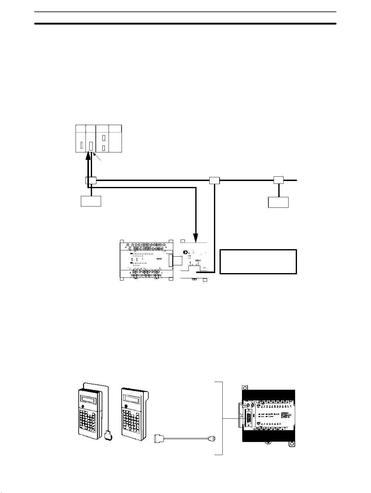
1-2-6 CompoBus/S I/O Link Connections
A CompoBus/S I/O Link can be used to create an I/O link (remote I/O) of 8 input
points and 8 output points with a CompoBus/S Master Unit or SRM1 PC. The
connection is made through a CompoBus/S I/O Link Unit.
From the standpoint of the CPM1A CPU Unit, the area allocated to the CompoBus/S I/O Link Unit can be treated just like the area allocated to an Expansion I/O
Unit. The difference is that the bits are not actual I/O points, but I/O bits in the
Master Unit.
RS-232C Cable
WX2Z-200T (2 m)
WX2Z-500T (5 m)
RS-232C
Adapter
CPM1A CPU Unit
CPM1-CIF01
SYSMAC CS-series PC
CompoBus/S Master Unit (or SRM1 PC)
CPM1A CPU Unit
(with 30 or 40 I/O points)
CompoBus/S I/O Link Unit
(Slave)
Cables
Use special flat cable, VCTF 2-core cable, or VCTF 4-core cable. Do not combine different types of cable in the same system.
Name Specifications
Flat cable 4-core flat cable, 0.75 mm
VCTF cable 2-core x 0.75 mm2, 4-core x 0.75 mm
2
2
(JIS C3306)
17
System Configuration
1-2-7 DeviceNet I/O Link Connections
A DeviceNet I/O Link Unit can be used to create an I/O link (remote I/O) of 32
input points and 32 output points with a DeviceNet master, i.e., the CPM1A operates as a DeviceNet slave. From the standpoint of the CPM1A CPU Unit, the
area allocated to the DeviceNet I/O Link Unit can be treated just like the area
allocated to an Expansion I/O Unit. The difference is that the bits are not actual
I/O points, but I/O bits in the DeviceNet master.
Up to three DeviceNet I/O Link Units can be connected, for a maximum DeviceNet I/O link capacity of 192 I/O points (96 inputs and 96 outputs).
CS-series, C200HX/HG/HE(-Z),
CVM1, or CV-series PC
DeviceNet (Master) Unit
DeviceNet transmission path
Section 1-2
DeviceNet slave
CPM1A CPU Unit (with
30 or 40 I/O points)
Remote I/O communications are
possible as a DeviceNet slave
for up to 32 input and 32 output
points for each Unit.
DeviceNet I/O Link Unit
(slave)
DeviceNet slave
1-2-8 Peripheral Device Connections
CPM1A programs can be created or edited with a Programming Console or a
personal computer running SYSMAC Support Software (SSS).
Programming Consoles A CQM1-PRO01-E or C200H-PRO27-E Programming Console can be con-
nected to the CPM1A as shown in the following diagram.
CPM1A CPU Unit
18
C200H-CN222/422
CQM1-PRO01-E C200H-PRO27-E
g
System Configuration
Section 1-2
Name Model number
CQM1 Programming Console
(The Connecting Cable is included.)
C200H/HS and C200HX/HG/HE Programming Console C200H-PRO27-E
C200H-series Connecting Cables
Cable length: 2 m C200H-CN222
Cable length: 4 m C200H-CN422
CQM1-PRO01-E
SYSMAC Support Software
and SYSMAC-CPT Support
Software
IBM PC/AT or compatible
SSS,
SYSMAC-CPT,
CX-Programmer
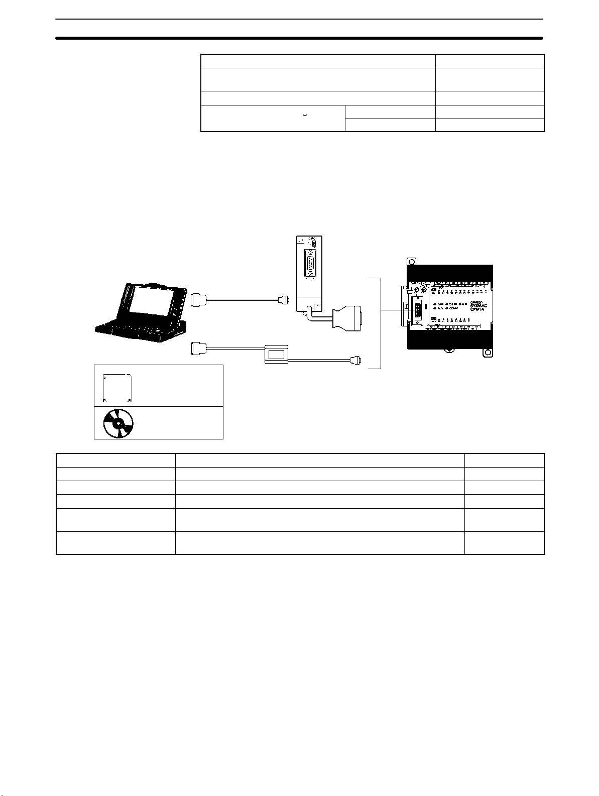
An IBM PC/AT or compatible personal computer running SSS or the SYSMACCPT Support Software can be connected to the CPM1A as shown in the following diagram. Refer to 3-4-7 Host Link Connections for a diagram showing the
standard wiring for the RS-232C cable.
Any version of the Support Software may be used. Refer to 4-1 Support Soft-
ware Capabilities for further details on installing and using Support Software.
RS-232C Adapter
CPM1A CPU Unit
RS-232C Cable
CQM1-CIF02
Name Usage Model number
RS-232C Adapter Converts to Peripheral Port format level communications. CPM1-CIF01
Connecting Cable Used to connect IBM PC/AT or compatible computers. (Length: 3.3 m) CQM1-CIF02
SYSMAC Support Software For IBM PC/AT or compatible computers (3.5” disks, 2HD) C500-ZL3AT1-E
SYSMAC-CPT Support
Software
CX-Programmer For Windows 95 or 98 computers
For IBM PC/AT or compatible computers
(3.5” disks (2HD) and CDROM)
(CDROM), version 1.2 or higher
WS01-CPTB1-E
WS02-CXPC1-E
19

SECTION 2
Unit Specifications and Components
This section provides the technical specifications of the Units that go together to create a CPM1A PC and describes the main
components of the Units.
2-1 Specifications 22. . . . . . . . . . . . . . . . . . . . . . . . . . . . . . . . . . . . . . . . . . . . . . . . . . . . . . . . . . . .
2-1-1 General Specifications 22. . . . . . . . . . . . . . . . . . . . . . . . . . . . . . . . . . . . . . . . . . . . . .
2-1-2 Characteristics 23. . . . . . . . . . . . . . . . . . . . . . . . . . . . . . . . . . . . . . . . . . . . . . . . . . . .
2-1-3 I/O Specifications 25. . . . . . . . . . . . . . . . . . . . . . . . . . . . . . . . . . . . . . . . . . . . . . . . .
2-1-4 Communications Adapter Specifications 30. . . . . . . . . . . . . . . . . . . . . . . . . . . . . . . .
2-2 Unit Components 31. . . . . . . . . . . . . . . . . . . . . . . . . . . . . . . . . . . . . . . . . . . . . . . . . . . . . . . . .
2-2-1 CPU Unit Components 31. . . . . . . . . . . . . . . . . . . . . . . . . . . . . . . . . . . . . . . . . . . . .
2-2-2 Expansion I/O Unit Components 33. . . . . . . . . . . . . . . . . . . . . . . . . . . . . . . . . . . . . .
2-2-3 Analog I/O Unit Components 35. . . . . . . . . . . . . . . . . . . . . . . . . . . . . . . . . . . . . . . .
2-2-4 Temperature Sensor Unit Components 36. . . . . . . . . . . . . . . . . . . . . . . . . . . . . . . . .
2-2-5 CompoBus/S I/O Link Unit Components 37. . . . . . . . . . . . . . . . . . . . . . . . . . . . . . .
2-2-6 DeviceNet I/O Link Unit Components 38. . . . . . . . . . . . . . . . . . . . . . . . . . . . . . . . .
2-2-7 Communications Adapter Components 40. . . . . . . . . . . . . . . . . . . . . . . . . . . . . . . . .
21

pp y
(AC t
Specifications Section 2-1
2-1 Specifications
2-1-1 General Specifications
Item
Supply
voltage
Operating
voltage
range
Power consumption
Inrush current 30 A max. 38 A max.
External
power
supply
ype
only)
(See note
1.)
Insulation resistance 20 MΩ min. (at 500 VDC) between the external AC terminals and protective earth terminals
Dielectric strength 2,300 VAC 50/60 Hz for 1 min between the external AC and protective earth terminals, leakage
Noise immunity Conforms to IEC6100-4-4; 2 kV (power lines)
Vibration resistance 10 to 57 Hz, 0.075-mm amplitude, 57 to 150 Hz, acceleration: 9.8 m/s2 in X, Y, and Z
Shock resistance 147 m/s2 three times each in X, Y, and Z directions
Ambient temperature Operating: 0° to 55°C
Humidity 10% to 90% (with no condensation)
Atmosphere Must be free from corrosive gas
Terminal screw size M3
Grounding
Power interrupt time AC type: 10 ms min.
CPU Unit
weight
Expansion I/O Unit
weight
Expansion Unit weight Analog I/O Unit: 150 g max.
AC type 100 to 240 VAC, 50/60 Hz
DC type 24 VDC
AC type 85 to 264 VAC
DC type 20.4 to 26.4 VDC
AC type 30 VA max. 60 VA max.
DC type 6 W max. 20 W max.
Supply
voltage
Output
capacity
AC type 400 g max. 500 g max. 600 g max. 700 g max.
DC type 300 g max. 400 g max. 500 g max. 600 g max.
CPM1A-10CDR-(-V1)
CPM1A-10CDT-(-V1)
CPM1A-10CDT1-(-V1)
24 VDC
200 mA (See note 2.) 300 mA
current: 10 mA max.
directions for 80 minutes each
(Time coefficient; 8 minutes × coefficient factor 10 = total time 80 minutes)
Storage: –20° to 75°C
Less than 100 W
DC type: 2 ms min.
(A power interruption occurs if power falls below 85% of the rated voltage for longer than the
power interrupt time.)
Units with 20 I/O points: 300 g max.
Units with 8 output points: 250 g max.
Units with 8 input points: 200 g max.
Temperature Sensor Units: 250 g max.
CompoBus/S I/O Link Unit: 200 g max.
DeviceNet I/O Link Unit: 200 g max.
CPM1A-20CDR-(-V1)
CPM1A-20CDT-(-V1)
CPM1A-20CDT1-(-V1)
CPM1A-30CDR-(-V1)
CPM1A-30CDT-(-V1)
CPM1A-30CDT1-(-V1)
CPM1A-40CDR-(-V1)
CPM1A-40CDT-(-V1)
CPM1A-40CDT1-(-V1)
Note 1. Use the external power supply as the service power supply of input devices.
The power supply cannot be used for driving output devices.
2. If there is an overcurrent or short on the external power supply, the voltage of
the external power supply will drop and the PC will stop operation.
22

capac y
pp
Specifications Section 2-1
2-1-2 Characteristics
Item
CPM1A-10CDR-(-V1)
CPM1A-10CDT-(-V1)
CPM1A-10CDT1-(-V1)
CPM1A-20CDR-(-V1)
CPM1A-20CDT-(-V1)
CPM1A-20CDT1-(-V1)
CPM1A-30CDR-(-V1)
CPM1A-30CDT-(-V1)
CPM1A-30CDT1-(-V1)
CPM1A-40CDR-(-V1)
CPM1A-40CDT-(-V1)
CPM1A-40CDT1-(-V1)
Control method Stored program method
I/O control method Cyclic scan with direct output; immediate refresh processing
Programming
Ladder diagram
language
Instruction length
Types of instructions
1 step per instruction, 1 to 5 words per instruction
Basic instructions: 14
Special instructions: 77 types, 135 instructions
Execution time Basic instructions: 0.72 to 16.2 µs
Special instructions: 16.3 µs (MOV instruction)
Program capacity 2,048 words
Max. I/O
capacity
CPU Unit
only
With
10 points 20 points 30 points 40 points
--- --- 50, 70, or 90 points 60, 80, or 100 points
Expansion
I/O Units
Input bits 00000 to 00915
Output bits 01000 to 01915
Words not used for input or output bits can be
used for work bits.
Work bits 512 bits: 20000 to 23115 (Words IR 200 to IR 231)
Special bits (SR area) 384 bits: 23200 to 25515 (Words IR 232 to IR 255)
Temporary bits (TR
8 bits (TR0 to TR7)
area)
Holding bits (HR area) 320 bits: HR 0000 to HR 1915 (Words HR 00 to HR 19)
Auxiliary bits (AR
256 bits: AR 0000 to AR 1515 (Words AR 00 to AR 15)
area)
Link bits (LR area) 256 bits: LR 0000 to LR 1515 (Words LR 00 to LR 15)
Timers/Counters 128 timers/counters (TIM/CNT 000 to TIM/CNT 127)
100-ms timers: TIM 000 to TIM 127
10-ms timers (high-speed counter): TIM 000 to TIM 127 (see note 1)
(the timer numbers used are the same as for the 100-ms timers)
Decrementing counters and reversible counters
Data memory Read/Write: 1,024 words (DM 0000 to DM 1023)
Read-only: 512 words (DM 6144 to DM 6655)
Interrupt processing
External interrupts: 2 External interrupts: 4
(see note 2)
Interval timer
1 (0.5 to 319,968 ms in Scheduled Interrupt Mode or Single Interrupt Mode)
interrupts
Memory protection HR and read/write DM area contents; and counter values maintained during power
interruptions.
Memory backup Flash memory:
The program, read-only DM area, and PC Setup area are backed up without a battery.
Capacitor backup:
The read/write DM area, error log area, HR area, and counter values are backed up by a
capacitor for 20 days at 25C. The capacitor backup time depends on the ambient
temperature. See the graph on the following page for details.
Self-diagnostic
CPU Unit failure (watchdog timer), I/O bus error, and memory failure
functions
Program checks No END instruction, programming errors (continuously checked during operation)
High-speed counter One high-speed counter: 5 kHz single-phase or 2.5 kHz two-phase (linear count method)
Increment mode: 0 to 65,535 (16 bits)
Up/Down mode: –32,767 to 32,767 (16 bits)
Quick-response inputs The same inputs are used for quick-response inputs and external interrupt inputs.
(Min. input pulse width: 0.2 ms)
23

Specifications Section 2-1
Item
Pulse output One point, 20 Hz to 2 kHz (single-phase output)
Input time constant Can be set to 1 ms, 2 ms, 4 ms, 8 ms, 16 ms, 32 ms, 64 ms, or 128 ms.
Analog controls 2 controls, setting range: 0 to 200 BCD
CPM1A-10CDR-(-V1)
CPM1A-10CDT-(-V1)
CPM1A-10CDT1-(-V1)
Can preset the pulse rate (1 to 16,777,215).
CPM1A-20CDR-(-V1)
CPM1A-20CDT-(-V1)
CPM1A-20CDT1-(-V1)
CPM1A-30CDR-(-V1)
CPM1A-30CDT-(-V1)
CPM1A-30CDT1-(-V1)
CPM1A-40CDR-(-V1)
CPM1A-40CDT-(-V1)
CPM1A-40CDT1-(-V1)
Note 1. Use TIM 000 to TIM 003 when creating a timer using the high-speed timer
instruction to perform interrupt processing.
2. The input interrupt response time is 0.3 ms max.
Memory Backup The user program and memory area data in the CPM1A are backed up either by
an internal capacitor or in flash memory as shown in the following table.
Backup method Data
Internal capacitor Read/write DM area (DM 0000 to DM 0999, DM 1022, and
Flash memory User program
DM 1023)
Error log area (DM 1000 to DM 1021)
HR area (HR 00 to HR 19)
Counter area (CNT 000 to CNT 127)
Read-only DM area (DM 6144 to DM 6599)
PC Setup (DM 6600 to DM 6655)
Note 1. The IR, TR, LR, and timer areas are not normally backed up when power is
turned off and all contents will be cleared the next time power is turned on.
(The PC Setup setting in DM 6601 can be used to back up this data. Refer to
details on the PC Setup later in this manual for details.)
2. The bits in the AR and SR areas have special functions and are set according to these functions when power is turned on.
The capacitor backup time depends on the ambient temperature, as shown in
the following graph. The backup time, however, assumes that the capacitor is
fully charged, which requires that power be supplied to the CPU Unit continuously for at least 15 minutes.
20
10
Backup time (days)
7
1
25 40 80
Ambient temperature (C)
24
If the power remains off for a period exceeding the data backup period,
AR 1314 will turn ON to indicate that the capacitor can no longer back up data
and the data backed up by the capacitor will be cleared. AR 1314 will remain
ON unless it is turned OFF using I/O monitor operations, using memory clear
operations, or from the user program.
If desired, the PC Setup setting in DM 6604 can be set to create a fatal error
and thus stop the system when AR 1314 goes ON.

Specifications Section 2-1
The data stored in flash memory will not be lost even if power remains off for a
period exceeding the data backup period, because the data stored in flash
memory will be read to the CPU Unit when the CPM1A is turned on.
If the power is turned off without changing the mode from PROGRAM mode to
RUN or MONITOR mode after having made changes in the data that is backed
up in flash memory, the changes will not be written to flash memory. If the power
is then left off for more than 20 days (at 25C), the changes (i.e., the contents of
the RAM) will be erased and the data values will become undefined.
Either switch the CPM1A to RUN or MONITOR mode, or turn off and on power to
the CPM1A after changing from a Programming Device any data that is backed
up in flash memory. This data includes the user program, read-only DM area
(DM 6144 to DM 6599), and the PC Setup (DM 6600 to DM 6655).
2-1-3 I/O Specifications
CPU Unit Input Specifications
Item Specification
Input voltage 24 VDC
Input impedance IN00000 to IN00002: 2 kΩ; other inputs: 4.7 kΩ
Input current IN00000 to IN00002: 12 mA typical; other inputs: 5 mA typical
ON voltage 14.4 VDC min.
OFF voltage 5.0 VDC max.
ON delay 1 to 128 ms max. Default: 8 ms (see note.)
OFF delay 1 to 128 ms max. Default: 8 ms (see note.)
Circuit configuration
+10%
/
–15%
IN
4.7 kΩ
IN
(2 kΩ)
Input
LED
820 Ω
COM
Note Figures in parentheses are for IN00000 to IN00002.
(510 Ω)
Internal
Circuits
Note Using the PC Setup, 1, 2, 4, 8, 16, 32, 64, or 128 ms can be selected. When
IN00000 through IN00002 are used as high-speed counter inputs, the delays
are as shown in the following table.
Input Increment mode Differential phase mode
IN00000 (A-phase) 5 kHz
IN00001 (B-phase) Normal input
IN00002 (Z-phase) ON: 100 µs min.; OFF delay: 500 µs min.
2.5 kHz
The minimum delay is as follows.
Increment Mode (5 kHz Max.)
200 µs min.
90 µs
min.
A phase
ON
OFF
90 µs
min.
25

Specifications Section 2-1
Differential Phase Mode (2.5 kHz Max.) IN00000 (A phase), IN00001 (B
phase)
400 µs min.
ON
Phase A
OFF
ON
Phase B
OFF
IN00002 (Z phase)
T
T
T
1
2
T
3
4
T
1
T
T
T
: 90 µs min.
2
3
4
ON
Phase Z
OFF
When IN00003 through IN00006 are used as interrupt inputs, the delay is 0.3 ms
max. The delay is measured from the time that the input goes ON until the interrupt subroutine is executed.
Expansion I/O Unit Input Specifications
Item Specification
Input voltage 24 VDC
Input impedance 4.7 kΩ
Input current 5 mA typical
ON voltage 14.4 VDC min.
OFF voltage 5.0 VDC max.
ON delay 1 to 128 ms max. Default: 8 ms (see note.)
OFF delay 1 to 128 ms max. Default: 8 ms (see note.)
Circuit configuration
+10%
/
–15%
IN
4.7 kΩ
IN
100 µs min.
500 µs
min.
Input
LED
26
COM
820 Ω
Internal
Circuits
Note Using the PC Setup, 1, 2, 4, 8, 16, 32, 64, or 128 ms can be selected.
Caution Do not apply voltage in excess of the rated voltage to the input terminal. It may
!
result in damage to the product or fire.

Specifications Section 2-1
CPU Unit and Expansion I/O Unit Output Specifications
Relay Outputs
Item Specification
Max. switching capacity 2 A, 250 VAC (cosφ = 1)
2 A, 24 VDC
(4 A/common)
Min. switching capacity 10 mA, 5 VDC
Service life of relay Electrical: 150,000 operations (resistive load, 24 VDC) 100,000 operations (inductive
load, 220 VAC, cos φ=0.4)
Mechanical for pre-V1 Units: 10,000,000 operations
Mechanical for V1 Units: 20,000,000 operations
ON delay 15 ms max.
OFF delay 15 ms max.
Circuit configuration OUT
Output
LED
Pre-V1 Units
500
4
300
200
100
Life (x 10 )
50
30
20
10
5
3
2
Internal
Circuits
OUT
COM
Maximum
250 VAC: 2 A
24 VDC: 2 A
Note 1. The service life of relay output contacts shown in the table assumes the
worst conditions. The following graph shows the results of OMRON’s service life tests at a switching rate of 1,800 times/hour.
2. The CPM1A-20EDR Expansion I/O Unit with Relay Outputs does not conform to the EC Directives. Use the CPM1A-20EDR1 or CPM1A-8ER Expansion I/O Unit, which has the CE marking, when conformance to EC Directives is required.
V1 Units
120 VAC, resistive load
24 VDC, τ = 7 ms
120 VAC, cosφ = 0.4
240 VAC, cosφ = 0.4
24 VDC/240 VAC, resistive load
Switching rate:
1,800 times/hour
4
Life (x 10 )
120 VAC, resistive load
24 VDC, τ = 7 ms
120 VAC, cosφ = 0.4
240 VAC, cosφ = 0.4
24 VDC/240 VAC, resistive load
Switching rate:
1,800 times/hour
0.1 0.2 0.3 0.5 0.7 1 2 3 5
Contact current (A)
Contact current (A)
27
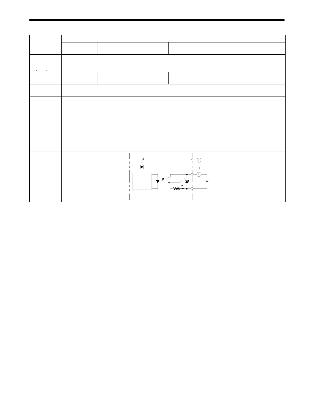
py
Specifications Section 2-1
Transistor Outputs (Sinking)
Item
CPM1A-
20CDT-(-V1)
, 0.3 A/point (see note) 4.5 to 30 VDC
–15%
CPM1A-
30CDT
Max.
switching
CPM1A-
10CDT-(-V1)
24 VDC
+10%
/
capacity
Leakage
0.9 A/Unit 0.9 A/common
1.8 A/Unit
0.1 mA max.
0.9 A/common
2.7 A/Unit
current
Residual
1.5 V max.
voltage
ON delay 0.1 ms max.
OFF delay OUT01000/01001: 0.2 ms max. (load current: 100 to 300 mA)
0.5 ms max. (load current: 5 to 100 mA)
Other than OUT01000/01001: 1 ms max. (load current: 5 to
300 mA)
Fuse V1 CPU Units: No fuse
Expansion I/O Units and Pre-V1 CPU Units 1.25 A/common (cannot be replaced by the user)
Circuit
Output LED
configuration
Specification
-(-V1)
CPM1A-
40CDT
-(-V1)
0.9 A/common
3.6 A/Unit
OUT
CPM1A-20EDT CPM1A-8ET
0.2 A (See note 2.)
0.3 A (See note 3.)
0.9 A/common
1.8 A/Unit
1 ms max.
(24 VDC
+10%
/
, 5 to 300 mA)
–5%
Internal
Circuits
OUT
COM (–)
24 VDC
Note When using the OUT01000 or OUT01001 as a pulse output, connect dummy
resistors as required to set the load current to 0.1 to 0.2 A. If the load current is
below 0.1 A, the ON-to-OFF response time will become longer and high-speed
pulse will not be output. On the other hand, if the load current is above 0.2 A, the
transistor may generate heat and components may be damaged.
28

py
Specifications Section 2-1
Transistor Outputs (Sourcing)
CPM1A-
Output LED
Specification
CPM1A-
40CDT1-(-V1)
0.9 A/common
3.6 A/Unit
COM (+)
OUT
CPM1A20EDT1
0.9 A/common
1.8 A/Unit
1 ms max.
(24 VDC
+10%
24 VDC
CPM1A-8ET1
0.2 A (See note 2.)
0.3 A (See note 3.)
/
, 5 to 300 mA)
–5%
Item
Max.
switching
CPM1A-
10CDT1-(-V1)
24 VDC
+10%
/
–15%
CPM1A-
20CDT1-(-V1)
30CDT1-(-V1)
, 0.3 A/point (See note.) 4.5 to 30 VDC
capacity
Leakage
0.9 A/Unit 0.9 A/common
1.8 A/Unit
0.1 mA max.
0.9 A/common
2.7 A/Unit
current
Residual
1.5 V max.
voltage
ON delay 0.1 ms max.
OFF delay OUT01000/01001: 0.2 ms max. (load current: 100 to 300 mA)
0.5 ms max. (load current: 5 to 100 mA)
Other than OUT01000/01001: 1 ms max. (load current: 5 to 300 mA)
Fuse V1 CPU Units: No fuse
Expansion I/O Units and Pre-V1 CPU Units 1.25 A/common (cannot be replaced by the user)
Circuit
configuration
Internal
Circuits
OUT
Note When using the OUT01000 or OUT01001 as a pulse output, connect dummy
resistors as required to set the load current to 0.1 to 0.2 A. If the load current is
below 0.1 A, the ON-to-OFF response time will become longer and high-speed
pulse will not be output. On the other hand, if the load current is above 0.2 A, the
transistor may generate heat and components may be damaged.
Caution Do not apply voltage in excess of the maximum switching capacity to an output
!
terminal. It may result in damage to the product or fire.
29

Specifications Section 2-1
2-1-4 Communications Adapter Specifications
RS-232C Adapter Specifications
Item Specification
Function Converts between the CMOS format (PC CPU Unit side) and the RS-232C format
(peripheral device side).
Insulation The RS-232C (peripheral device side) is isolated by a DC/DC convertor and photocoupler.
Power supply Power is supplied from the PC CPU Unit.
Power consumption 0.3 A max.
Baud rate 38,400 bps max.
Transmission distance Total length:15 m max.
Vibration resistance 10 to 57 Hz: 0.075-mm amplitude
57 to 150 Hz: 9.8 m/s2 acceleration in X, Y, and Z directions for 80 minutes each
(Time coefficient; 8 minutes × coefficient factor 10 = total time 80 minutes)
Shock resistance 147 m/s2 three times each in X, Y, and Z directions
Ambient temperature Operating: 0° to 55°C
Storage: –20° to 75°C
Humidity 10% to 90% (with no condensation)
Atmosphere Must be free from corrosive gas
Weight 200 g max.
RS-422 Adapter Specifications
Item Specification
Function Converts between the CMOS format (PC CPU Unit side) and the RS-422 format (peripheral
device side).
Insulation The RS-422 (peripheral device side) is isolated by a DC/DC convertor and photocoupler.
Power supply Power is supplied from the PC CPU Unit.
Power consumption 0.3 A max.
Baud rate 38,400 bps max.
Transmission distance Total length: 500 m max.
Vibration resistance 10 to 57 Hz: 0.075-mm amplitude
57 to 150 Hz: 9.8 m/s2 acceleration in X, Y, and Z directions for 80 minutes each
(Time coefficient; 8 minutes × coefficient factor 10 = total time 80 minutes)
Shock resistance 147 m/s2 three times each in X, Y, and Z directions
Ambient temperature Operating: 0° to 55°C
Storage: –20° to 75°C
Humidity 10% to 90% (with no condensation)
Atmosphere Must be free from corrosive gas
Weight 200 g max.
30

Unit Components
2-2 Unit Components
2-2-1 CPU Unit Components
CPU Units with 10 I/O Terminals
CPM1A-10CDR--V1/10CDT--V1/10CDT1--V1
1. Power supply input terminals
Section 2-2
3. Protective earth terminal
5. Input terminals
10. Analog controls
11. Peripheral Port
4. Power supply output terminals
(AC power supplies only)
CPM1A-10CDR-/10CDT-/10CDT1-
2. Functional earth terminal
(AC power supplies only)
1. Power supply input terminals
8. Input indicators
9. Output indicators
7. PC status indicators
6. Output terminals
3. Protective earth terminal
5. Input terminals
10. Analog controls
11. Peripheral Port
4. Power supply output terminals
(AC power supplies only)
8. Input indicators
7. PC status indicators
9. Output indicators
6. Output terminals
31

Unit Components
CPU Units with 20 I/O Terminals
CPU Units with 30 I/O Terminals
Section 2-2
CPM1A-20CDR-/20CDT-/20CDT1-CPM1A-20CDR--V1/20CDT--V1/20CDT1--V1
CPM1A-30CDR-/30CDT-/30CDT1-CPM1A-30CDR--V1/30CDT-/-V130CDT1--V1
CPU Units with 40 I/O Terminals
12. Expansion
CPU Unit Component Descriptions
1, 2, 3... 1. Power Supply Input Terminals
Connect the power supply (100 to 240 VAC or 24 VDC) to these terminals.
2. Functional Earth Terminal (
Be sure to ground this terminal (AC-type PCs only) to enhance immunity to
noise and reduce the risk of electric shock.
12. Expansion
I/O Unit
connector
I/O Unit
connector
12. Expansion
I/O Unit
connector
CPM1A-40CDR-/40CDT-/40CDT1-CPM1A-40CDR--V1/40CDT--V1/40CDT1--V1
12. Expansion
I/O Unit
connector
) (Pre-V1 CPU Units only)
32
3. Protective Earth Terminal (
)
Be sure to ground this terminal to reduce the risk of electric shock.
4. Power Supply Output Terminals
CPM1A PCs are equipped with these 24-VDC power output terminals to
supply power to input devices. (AC-type PCs only.)
5. Input Terminals
Connect the Unit to external input devices.
6. Output Terminals
Connect the Unit to external output devices.

(g )
(g )
(g)
Unit Components
Section 2-2
7. PC Status Indicators
These indicators show the operating status of the PC, as shown in the following table.
Indicator Status Meaning
PWR (green)
RUN (green)
ERR/ALARM
(red)
COMM (orange)
8. Input Indicators
These indicators are lit when the corresponding input terminal is ON.
When a fatal error occurs, the input indicators change as follows:
ON Power is being supplied to the PC.
OFF Power isn’t being supplied to the PC.
ON The PC is operating in RUN or MONITOR mode.
OFF The PC is in PROGRAM mode or a fatal error
has occurred.
ON A fatal error has occurred. (PC operation stops.)
Flashing A non-fatal error has occurred. (PC operation
continues.)
OFF Indicates normal operation.
ON Data is being transferred via the Peripheral Port.
OFF Data isn’t being transferred via the Peripheral
Port.
Fatal error Input indicators
CPU Unit error or I/O bus error Turn OFF.
Memory error, no END instruction
error, or system error
9. Output Indicators
These indicators are lit when the corresponding output terminal is ON.
10. Analog Controls
Setting these controls sets the contents of IR 250 and IR 251 from 0 to 200.
11. Peripheral Port
Connects the PC to a Peripheral Device, RS-232C Adapter, or RS-422
Adapter.
12. Expansion I/O Unit Connector
Connects the PC’s CPU Unit to an Expansion I/O Unit to add another 12
input points and 8 output points. Up to 3 Expansion I/O Units can be connected.
2-2-2 Expansion I/O Unit Components
Expansion I/O Unit with 20 I/O Terminals
The indicators will change with the
status of the input signal, but input
status will not be updated in memory.
1. Input terminals
5. Expansion I/O Unit Connecting Cable
3. Input indicators
6. Expansion connector
4. Output indicators
2. Output terminals
33

Unit Components
5. Expansion I/O Unit Connecting Cable
Section 2-2
Expansion I/O Unit with 8 Input Terminals
1. Input terminals
3. Input indicators
6. Expansion connector
1. Input terminals
Expansion I/O Unit with 8 Output Terminals
2. Output terminals
5. Expansion I/O Unit Connecting Cable
1, 2, 3... 1. Input Terminals
Connects the Unit to external input devices.
2. Output Terminals
Connects the Unit to external output devices.
3. Input Indicators
The input indicators are lit when the corresponding input terminal is ON.
4. Output Indicators
The output indicators are lit when the corresponding output terminal is ON.
5. Expansion I/O Unit Connecting Cable
Connects the Expansion I/O Unit to the Expansion Connector on the PC’s
CPU Unit or another Expansion Unit.
4. Output indicators
6. Expansion connector
2. Output terminals
34
Caution Do not touch the Expansion I/O Unit Connecting Cable while the power is being
!
supplied in order to prevent any malfunction due to static electricity.
6. Expansion Connector
Connects to another Expansion Unit (Expansion I/O Unit, Analog I/O Unit, or
CompoBus/S I/O Link Unit). Up to 3 Expansion Units can be connected to a
CPU Unit.
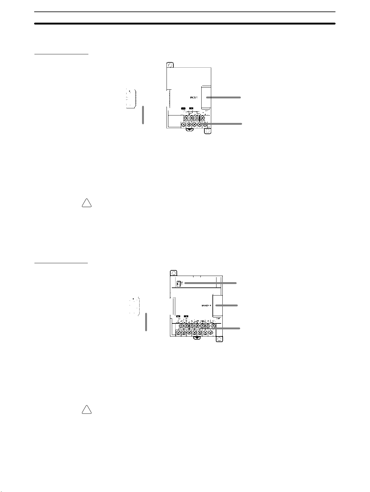
Unit Components
2-2-3 Analog I/O Unit Components
CPM1A-MAD01
Section 2-2
3. Expansion connector
2. Expansion I/O Unit Connecting Cable
CPM1A-MAD11
1. Analog I/O terminals
1, 2, 3... 1. Analog I/O Terminals
Connects the Unit to analog input devices and analog output devices.
2. Expansion I/O Unit Connecting Cable
Connects the Analog I/O Unit to the Expansion Connector on the PC’s CPU
Unit or another Expansion Unit. The cable is connected to the Analog I/O
Unit and cannot be removed.
Caution Do not touch the Expansion I/O Unit Connecting Cable while the power is being
!
supplied in order to prevent any malfunction due to static electricity.
3. Expansion Connector
Connects to another Expansion Unit (Expansion I/O Unit, Analog I/O Unit, or
CompoBus/S I/O Link Unit). Up to 3 Expansion Units can be connected to a
CPU Unit.
4. DIP Switch
3. Expansion connector
1. Analog I/O terminals
2. Expansion I/O Unit Connecting Cable
1, 2, 3... 1. Analog I/O Terminals
Connects the Unit to analog input devices and analog output devices.
2. Expansion I/O Unit Connecting Cable
Connects the Analog I/O Unit to the Expansion Connector on the PC’s CPU
Unit or another Expansion Unit. The cable is connected to the Analog I/O
Unit and cannot be removed.
Caution Do not touch the Expansion I/O Unit Connecting Cable while the power is being
!
supplied in order to prevent any malfunction due to static electricity.
3. Expansion Connector
Connects to another Expansion Unit (Expansion I/O Unit, Analog I/O Unit, or
CompoBus/S I/O Link Unit). Up to 3 Expansion Units can be connected to a
CPU Unit.
35

Unit Components
4. DIP Switch
Used to set averaging processing.
2-2-4 Temperature Sensor Unit Components
The following Temperature Sensor Units are available: CPM1A-TS001,
CPM1A-TS002, CPM1A-TS101, and CPM1A-TS102.
Section 2-2
2. DIP switch
4. Expansion I/O connecting cable
1, 2, 3... 1. Temperature Input Terminals
2. DIP Switch
3. Rotary switch
5. Expansion connector
1. Temperature input terminals
Connect to a thermocouple or a platinum resistance thermometer.
Sets the temperature unit (°C or °F), and the number of decimal places
used.
ON
12
Number of decimal places used
OFF: Normal (0 or 1); ON: 2
Temperature unit
OFF: °C; ON: °F
3. Rotary Switch
Sets the temperature range. Set the range in accordance with the specifica-
tions of the temperature sensor used.
CPM1A-TS001/002
Set value Thermocouple Range (°C) Range (°F)
0
1 0.0 to 500.0 0.0 to 900.0
2
3 0.0 to 400.0 0.0 to 750.0
4 to F --- Setting not possible
K
J
–200 to 1,300 –300 to 2,300
–100 to 850 –100 to 1,500
CPM1A-TS101/102
Set value Platinum resistance
thermometer
0 Pt100 –200.0 to 650.0 –300.0 to 1,200.0
1 JPt100 –200.0 to 650.0 –300.0 to 1,200.0
2 to F --- Setting not possible
Range (°C) Range (°F)
36
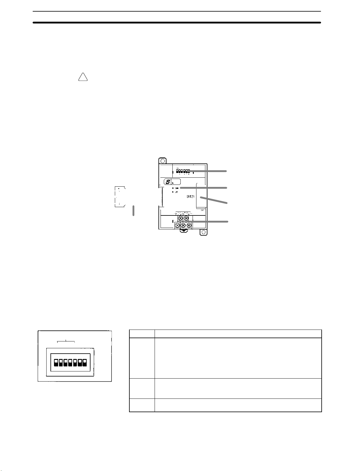
Unit Components
4. Expansion I/O Connecting Cable
Connects the Temperature Sensor Unit to the expansion connector on the
PC’s CPU Unit, an Expansion I/O Unit, or another Expansion Unit. The cable
is connected to the Temperature Sensor Unit and cannot be removed.
Caution Do not touch the expansion I/O connecting cable while the power is being sup-
!
plied in order to prevent any malfunction due to static electricity.
5. Expansion Connector
Connects to an additional Expansion I/O Unit or another Expansion Unit.
2-2-5 CompoBus/S I/O Link Unit Components
The following CompoBus/S I/O Link Unit is available: CPM1A-SRT21.
Section 2-2
2. DIP switch
3. LED indicators
4. Expansion I/O Unit Connecting Cable
NODE ADDRESS
124
ON
1, 2, 3... 1. CompoBus/S Terminals
Include the CompoBus/S communications data high/low terminal, communications power supply +/– terminals, and NC terminals. Power is supplied
to the Unit internally, so the power supply terminals can be used as relay
terminals.
2. DIP Switch
The DIP switch sets the Unit’s node address, sets the communications
mode, and determines whether or not the outputs will be cleared in the event
of a communications error.
Pin(s) Function
8
DR
HOLD
SW1
1 to 4
(labeled
1, 2, 4,
and 8)
DR ON: Long-distance Communications Mode
HOLD ON: Retain outputs when a communications error occurs.
5. Expansion connector
1. CompoBus/S terminals
These pins set the Unit’s node address using the DIP switch pins as
binary digits. (1 = ON)
0: 0000 1: 0001 2: 0010 3: 0011
4: 0100 5: 0101 6: 0110 7: 0111
8: 1000 9: 1001 10: 1010 11: 1011
12: 1100 13: 1101 14: 1110 15: 1111
OFF: High-speed Communications Mode
(See note.)
OFF: Clear outputs when a communications error occurs.
Note The Long-distance Communications Mode can be used only when connected to
one of the following Master Units: C200HW-SRM21-V1, CQM1-SRM21-V1, or
SRM1-C0-V2.
37
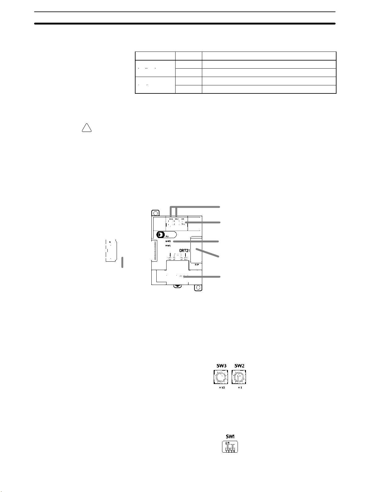
Unit Components
3. LED Indicators
These indicators show the status of CompoBus/S communications.
Indicator Status Meaning
COMM
(yellow)
ERR
(red)
ON Communications in progress.
OFF Communications error or stopped.
ON A communications error has occurred.
OFF Indicates normal or no communications.
4. Expansion I/O Unit Connecting Cable
Connects the CompoBus/S I/O Link Unit to the Expansion Connector on the
PC’s CPU Unit or another Expansion Unit.
Caution Do not touch the Expansion I/O Unit Connecting Cable while the power is being
!
supplied in order to prevent any malfunction due to static electricity.
5. Expansion Connector
Connects to another Expansion Unit (Expansion I/O Unit, Analog I/O Unit, or
CompoBus/S I/O Link Unit). Up to 3 Expansion Units can be connected to a
CPU Unit.
2-2-6 DeviceNet I/O Link Unit Components
The following DeviceNet I/O Link Unit is available: CPM1A-DRT21.
Section 2-2
5. Expansion I/O Unit Connecting Cable
1, 2, 3... 1. DeviceNet Communications Terminals
Connect these terminals to the DeviceNet transmission path. Use either the
enclosed connector or another connector for wiring.
2. Rotary Switches (SW2 and SW3)
The rotary switches are used to set the DeviceNet node address of the Unit
between 00 and 64. (Do not set values 64 to 99.)
2. Rotary switches
3. DIP switches
4. LED indicators
6. Expansion connector
1. DeviceNet communications terminals
38
3. DIP Switch (SW1)
The DIP switch sets the baud rate and determines whether or not the out-
puts will be cleared in the event of a communications error.

Unit Components
Section 2-2
Baud Rate Setting
Pin 1 Pin 2 DeviceNet baud rate Max. transmission path
length (reference value)
OFF OFF 125 kbps 500 m max.
ON OFF 250 kbps 250 m max.
OFF ON 500 kbps 100 m max.
ON ON Do not set.
Output Hold Setting
Pin 4 Output treatment for communications errors
OFF Clear outputs when a communications error occurs.
ON Retain outputs when a communications error occurs.
4. LED Indicators
Indi-
Color Status Definition Meaning
cator
MS Green
Red
--- OFF No Power Power isn’t being supplied, waiting for
NS Green
Red
--- OFF Not
ON Device
Operational
Flashing Device in
Standby
ON Unrecover-
able Fault
Flashing Minor Fault Switch settings incorrect, etc.
ON On-line,
Connected.
Flashing On-line, Not
Connected
ON Fatal Com-
munications
Error
Flashing Non–fatal
communications error
Powered/
Not On-Line
Normal operating status.
Reading switch settings.
Unit hardware error: Watchdog timer error
initial processing, or Unit is being reset.
Network is operating normally
(communications established)
Network is operating normally, but
communications are not yet established.
A fatal communications error has
occurred. Network communications are
not possible. Check for a node address
duplication or Bus Off error.
Communications timeout or
communications error for some of the
slaves.
Checking for node address duplication on
the master, switch settings are incorrect,
or the power supply is OFF.
5. Expansion I/O Unit Connecting Cable
Connects the DeviceNet I/O Link Unit to the Expansion Connector on the
PC’s CPU Unit or another Expansion Unit. This cable cannot be removed.
Caution Do not touch the Expansion I/O Unit Connecting Cable while the power is being
!
supplied in order to prevent any malfunction due to static electricity.
6. Expansion Connector
Connects to another Expansion Unit or Expansion I/O Unit
39
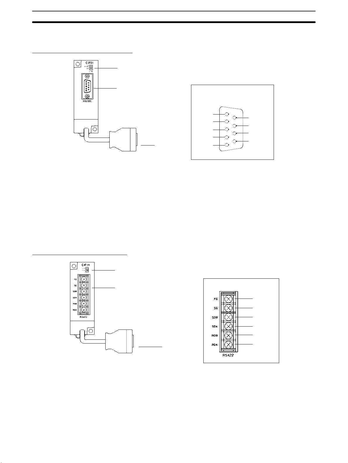
Unit Components
2-2-7 Communications Adapter Components
CPM1-CIF01 RS-232C Adapter
1. Mode Setting Switch
3. RS-232C port
FG
SD
RD
RTS
2. Connector
1, 2, 3... 1. Mode Setting Switch
Set this switch to “HOST” when using a Host Link system to connect to a
personal computer. Set this switch to “NT” when connecting to a Programmable Terminal or PC for 1:1 PC Link.
2. Connector
Connects to the CPU Unit’s Peripheral Port.
3. RS-232C Port
Connects to the RS-232C cable from the other device such as a personal
computer, Peripheral Device, or Programmable Terminal.
CTS
RS-232C Port Pin Allocation
1
2
3
4
5
6
7
8
9
DCD
DSR
DTR
SG
Section 2-2
CPM1-CIF11 RS-422 Adapter
1. Termination Resistance Switch
3. RS-422 port
1, 2, 3... 1. Termination Resistance Switch
2. Connector
3. RS-422 Port
RS-422 Port Pin Allocation
FG
SG
SDB
SDA
RDB
2. Connector
RDA
Set the termination resistance switch to “ON” (upper side) for the Link
Adapters on both ends of the Host Link system and for the RS-422 Adapter.
Connects to the CPU Unit’s Peripheral Port.
Connects to the Host Link network.
40

SECTION 3
Installation and Wiring
This section provides information on installing and wiring a CPM1A PC. Be sure to follow the directions and precautions in
this section when installing the CPM1A in a panel or cabinet, wiring the power supply, or wiring I/O.
3-1 Design Precautions 42. . . . . . . . . . . . . . . . . . . . . . . . . . . . . . . . . . . . . . . . . . . . . . . . . . . . . . . .
3-1-1 Power Supply Wiring 42. . . . . . . . . . . . . . . . . . . . . . . . . . . . . . . . . . . . . . . . . . . . . . .
3-1-2 Interlock and Limit Circuits 42. . . . . . . . . . . . . . . . . . . . . . . . . . . . . . . . . . . . . . . . . .
3-1-3 Power Supply Voltage 42. . . . . . . . . . . . . . . . . . . . . . . . . . . . . . . . . . . . . . . . . . . . . .
3-1-4 CPM1A Power Interruptions 42. . . . . . . . . . . . . . . . . . . . . . . . . . . . . . . . . . . . . . . . .
3-2 Selecting an Installation Site 43. . . . . . . . . . . . . . . . . . . . . . . . . . . . . . . . . . . . . . . . . . . . . . . .
3-2-1 Installation Site Conditions 43. . . . . . . . . . . . . . . . . . . . . . . . . . . . . . . . . . . . . . . . . .
3-2-2 Panel/Cabinet Installation 44. . . . . . . . . . . . . . . . . . . . . . . . . . . . . . . . . . . . . . . . . . .
3-3 Installing the CPM1A 45. . . . . . . . . . . . . . . . . . . . . . . . . . . . . . . . . . . . . . . . . . . . . . . . . . . . . .
3-3-1 CPM1A Orientation 45. . . . . . . . . . . . . . . . . . . . . . . . . . . . . . . . . . . . . . . . . . . . . . . .
3-3-2 CPM1A Installation 45. . . . . . . . . . . . . . . . . . . . . . . . . . . . . . . . . . . . . . . . . . . . . . . .
3-3-3 Connecting an Expansion I/O Unit 47. . . . . . . . . . . . . . . . . . . . . . . . . . . . . . . . . . . .
3-4 Wiring and Connections 50. . . . . . . . . . . . . . . . . . . . . . . . . . . . . . . . . . . . . . . . . . . . . . . . . . . .
3-4-1 General Precautions for Wiring 50. . . . . . . . . . . . . . . . . . . . . . . . . . . . . . . . . . . . . . .
3-4-2 Ground Wiring 51. . . . . . . . . . . . . . . . . . . . . . . . . . . . . . . . . . . . . . . . . . . . . . . . . . . .
3-4-3 Power Supply Wiring 52. . . . . . . . . . . . . . . . . . . . . . . . . . . . . . . . . . . . . . . . . . . . . . .
3-4-4 Input Wiring 55. . . . . . . . . . . . . . . . . . . . . . . . . . . . . . . . . . . . . . . . . . . . . . . . . . . . . .
3-4-5 Output Wiring 61. . . . . . . . . . . . . . . . . . . . . . . . . . . . . . . . . . . . . . . . . . . . . . . . . . . .
3-4-6 Peripheral Device Connection 69. . . . . . . . . . . . . . . . . . . . . . . . . . . . . . . . . . . . . . . .
3-4-7 Host Link Connections 69. . . . . . . . . . . . . . . . . . . . . . . . . . . . . . . . . . . . . . . . . . . . .
3-4-8 One-to-one PC Link Connections 72. . . . . . . . . . . . . . . . . . . . . . . . . . . . . . . . . . . . .
3-4-9 One-to-one NT Link Connections 73. . . . . . . . . . . . . . . . . . . . . . . . . . . . . . . . . . . . .
3-4-10 CompoBus/S I/O Link Unit Connections 74. . . . . . . . . . . . . . . . . . . . . . . . . . . . . . .
3-4-11 DeviceNet I/O Link Unit Connections 75. . . . . . . . . . . . . . . . . . . . . . . . . . . . . . . . .
41

Design Precautions Section 3-1
3-1 Design Precautions
Observe the following precautions when designing a system incorporating a
CPM1A PC.
3-1-1 Power Supply Wiring
Separate the power supply wiring from the control system, CPM1A system, and
DC I/O system wiring. Separate the control circuits that supply power to the main
Unit from the main circuits using dedicated circuit protectors and fuses.
3-1-2 Interlock and Limit Circuits
WARNING Emergency stop circuits, interlock circuits, limit circuits, and similar safety
!
measures must be provided in external control circuits (i.e., not in the
Programmable Controller) to ensure safety in the system if an abnormality
occurs due to malfunction of the PC or another external factor affecting the PC
operation. Not providing proper safety measures may result in serious
accidents.
Construct an external interlock circuit if CPM1A outputs are used to perform
reciprocal operations such as controlling the forward and reverse operation of a
motor or if incorrect PC operation could cause accidents or mechanical damage.
Also, construct an external limit circuit to prevent run-away movement in systems such as position control.
The following diagram shows an example of an interlock circuit.
In the interlock circuit above, MC1 and MC2 can’t be ON at the same time even if
CPM1A outputs 01005 and 01006 are both ON (an incorrect PC operation).
3-1-3 Power Supply Voltage
Caution Use the power supply voltages indicated in Section 2 Unit Specifications and
!
Components. Failure to adhere to the specifications may result in fire. In places
where power supply conditions are poor, take steps to ensure that power is supplied at the rated voltage. Be sure to adhere to safety precautions, such as providing breakers to prevent short circuits in external wiring. When conducting any
of the following operations, turn OFF the power to the PC. Electric shock, product damage and malfunction may result.
• Connecting or disconnecting Expansion I/O Units and CPU Units.
• Assembling Units
• Connecting cables and wiring.
CPM1A
Interlock Circuit
01005
01006
MC2
MC1
MC1
MC2
Motor forward
Motor reverse
3-1-4 CPM1A Power Interruptions
Supply Voltage Drop
When the supply voltage falls below 85% of the rated value, the PC will stop and
the outputs will go OFF.
42

Selecting an Installation Site
Section 3-2
Momentary Power Failure Detection
A momentary power failure lasting less than 10 ms with an AC power supply and
2 ms with a DC power supply is not detected and the CPU Unit continues to operate.
A momentary power failure lasting longer than 10 ms with an AC power supply
and 2 ms with a DC power supply may or may not be detected in an uncertain
area.
When a momentary power failure is detected, the CPU Unit stops operating and
the output goes OFF.
Automatic Restart
When the supply voltage recovers to a value higher than 85% of the rated value,
operations resumes automatically.
Duration of power interrupt
(Below 85% of rated voltage)
Note The CPM1A may repeat stop/start operations if the supply voltage of less than
85% of the rated value gradually goes up or down.
If this affects the equipment, etc., provide a protection circuit which shuts off the
output if the supply voltage is not above the rated value.
Time Up to the Start of Operation
The time from when the power supply is turned on to when the operation starts
varies depending on the operation conditions such as power supply voltage,
configuration, ambient temperature, etc. The minimum time is approximately
300 ms.
3-2 Selecting an Installation Site
The CPM1A is resistant to harsh conditions and highly reliable, but installing the
PC in a favorable site will maximize its reliability and operating lifetime.
Caution Be sure to install the CPM1A correctly, as outlined in this manual. Failure to do so
!
may result in Unit malfunction.
Under Over
Normal operation Operation may stop.
10 ms (2 ms)
All outputs go OFF when
operations stop.
3-2-1 Installation Site Conditions
Note Do not install the CPM1A under any of the following conditions.
• Locations subject to direct sunlight.
• Locations subject to a temperature below 0°C or over 55°C.
• Locations subject to a humidity below 10% or over 90%.
• Locations subject to condensation as the result of severe changes in tempera-
ture.
• Locations subject to corrosive or flammable gases.
• Locations subject to dust (especially iron dust) or salts.
• Locations subject to shock or vibration.
• Locations subject to exposure to water, oil, or chemicals.
Be sure that the conditions at the installation site conform to the CPM1A’s general specifications. Refer to 2-1-1 General Specifications for details.
43

Selecting an Installation Site
Section 3-2
Note Provide proper shielding when installing in the following locations:
• Locations subject to static electricity or other sources of noise.
• Locations subject to strong electromagnetic fields.
• Locations subject to possible exposure to radiation.
• Locations near to power supply lines.
3-2-2 Panel/Cabinet Installation
Consider PC operation, maintenance, and surrounding conditions when installing the CPM1A in a panel or cabinet.
Overheating The operating temperature range for the CPM1A is 0C to 55C. Be sure that
there is adequate ventilation for cooling.
• Allow enough space for air circulation.
• Do not install the CPM1A above equipment that generates a large amount of
heat, such as heaters, transformers, or large resistors.
• Install a cooling fan or system when the ambient temperature exceeds 55C.
Control panel
Air vent
Fan
CPM1A
Electrical Noise Power lines and high-voltage equipment can cause electrical noise in the PC.
• Do not install the CPM1A in a panel or cabinet with high-voltage equipment.
• Allow at least 200 mm between the CPM1A and nearby power lines.
200 mm min.
CPM1A
200 mm min.
Accessibility Ensure that the CPM1A can be accessed for normal operation and mainte-
nance.
• Provide a clear path to the CPM1A for operation and maintenance. High-volt-
age equipment or power lines could be dangerous if they are in the way during
routine operations.
• The PC will be easiest to access if the panel or cabinet is installed about 3 to 5
feet off of the floor.
44

Installing the CPM1A
3-3 Installing the CPM1A
3-3-1 CPM1A Orientation
The CPM1A must be installed in the position shown below to ensure adequate
cooling.
Do not install the CPM1A in either of the following positions.
Section 3-3
Correct
Incorrect
Incorrect
3-3-2 CPM1A Installation
The CPM1A can be installed on a horizontal surface or on a DIN track.
Surface Installation Use the following pattern when installing a CPM1A on a horizontal surface.
CPM1A-10CDR-(-V1)/10CDT-(-V1)/10CDT1-(-V1) and
CPM1A-20CDR-(-V1)/20CDT-(-V1)/20CDT1-(-V1)
Two, M4 holes
100 mm
Use M4 dia. x 15 screws.
The width (A) between the mounting holes depends on the CPM1A model.
CPM1A-10CDR-(-V1)/10CDT-(-V1)/10CDT1-(-V1) CPU Unit
CPM1A-20CDR-(-V1)/20CDT-(-V1)/20CDT1-(-V1) CPU Unit
Allow 10 to 15 mm between the Units when installing a Communications Adapter
next to the CPU Unit, as shown below.
CPU Unit
A 8 mm
Model number Width (A)
56 mm
76 mm
21 mm
81 mm
Communications
Adapter
10 to
15 mm
CPU Unit
100 mm
45

p
g
Installing the CPM1A
Section 3-3
CPM1A-30CDR-(-V1)/30CDT-(-V1)/30CDT1-(-V1) and
CPM1A-40CDR-(-V1)/40CDT-(-V1)/40CDT1-(-V1)
Four, M4 holes
100 mm
CPU Unit
A
8 mm
Use M4 dia. x 15 screws.
The width (A) between the mounting holes depends on the CPM1A model.
Model number Width (A)
CPM1A-30CDR-(-V1)/30CDT-(-V1)/30CDT1-(-V1) CPU Units
CPM1A-40CDR-(-V1)/40CDT-(-V1)/40CDT1-(-V1) CPU Units
Expansion I/O Units
CPM1A-20ED
CPM1A-8E
Analog I/O Unit
CPM1A-MAD01 56 mm
120 mm
140 mm
76 mm
56 mm
CPM1A-MAD11 76 mm
CompoBus/S I/O Link Unit 56 mm
DeviceNet I/O Link Unit 56 mm
RS-232C Adapter 21 mm
RS-422 Adapter 21 mm
Temperature Sensor Unit 76 mm
Allow 10 to 15 mm between the Units when installing an Expansion Unit, Expansion I/O Unit, or Communications Adapter next to the CPU Unit, as shown below.
21 mm
CPU Unit
Communications
Adapter
10 to
15 mm
10 to
15 mm
A
DIN Track Installation The CPM1A can be installed on a 35-mm DIN Track.
End Plates
(PFP-M)
100 mm81 mm
Expansion Unit or
Expansion I/O Unit
DIN Track
PFP-100N (1 m)
PFP-50N (50 cm)
PFP-100N2 (1 m)
46

Installing the CPM1A
Section 3-3
Installation
Lower the CPM1A so that the notch on the back of the PC catches the top of the
DIN Track. Push the PC forward until the lock snaps into place.
Removal
Pry the lock down with a standard screwdriver and pivot the PC upward to
remove it.
3-3-3 Connecting an Expansion I/O Unit
Up to 3 Expansion I/O Units can be connected to the CPM1A-30CDR-(-V1)/
30CDT-(-V1)/30CDT1-(-V1) and CPM1A-40CDR-(-V1)/40CDT-(-V1)/
40CDT1-(-V1) CPU Units. Use the following procedure when connecting an
Expansion I/O Unit.
V1 Units
1, 2, 3... 1. Remove the cover from the CPU Unit’s Expansion I/O Unit Connector. Insert
a flat-blade screwdriver into the slot on the cover and press down lightly on
the handle of the screwdriver to remove it from the case.
Screwdriver
Screwdriver
Expansion I/O Unit
connector cover
47

Installing the CPM1A
Section 3-3
2. Insert the Expansion I/O Unit’s Connecting Cable into the CPU Unit’s
Expansion I/O Unit Connector.
3. Attach the cover to the CPU Unit’s Expansion I/O Unit Connector by inserting the two pins on the inside of the cover into the holes on the case and
pressing downward lightly and evenly.
48
4. When the pins are part way into the holes, press down on points (a) and (b)
in the following diagram alternately and firmly until the cover is securely in
place.
(a)
(b)

Installing the CPM1A
Pre-V1 Units
1, 2, 3... 1. Remove the cover from the CPU Unit’s or the Expansion I/O Unit’s Expan-
Section 3-3
sion I/O Unit Connector. Use a flat-blade screwdriver to remove the cover
from the Expansion I/O Connector.
Expansion I/O Unit
connector cover
2. Insert the Expansion I/O Unit’s Connecting Cable into the CPU Unit’s or the
Expansion I/O Unit’s Expansion I/O Unit Connector.
3. Replace the cover on the CPU Unit’s or the Expansion I/O Unit’s Expansion
I/O Unit Connector.
49

Wiring and Connections
3-4 Wiring and Connections
This section provides basic information on wiring the Power Supply Unit and
Expansion I/O Units, and on connecting Peripheral Devices.
3-4-1 General Precautions for Wiring
Caution With pre-V1 Units, attach the dustproof label provided before wiring. With V1
!
Units, leave the dustproof label in place while wiring. If scraps of wire get inside
the Unit, malfunction will result. After completing wiring be sure to remove the
label to avoid overheating.
Dustproof label
Section 3-4
I/O Line Noise Do not run CPM1A I/O lines in the same duct or conduit as power lines.
Hanging Ducts
Leave at least 300 mm between the power cables and the I/O or control wiring,
as shown in the following diagram.
CPM1A I/O lines
300 mm min.
Control cables and
CPM1A power lines
300 mm min.
Power cables
50
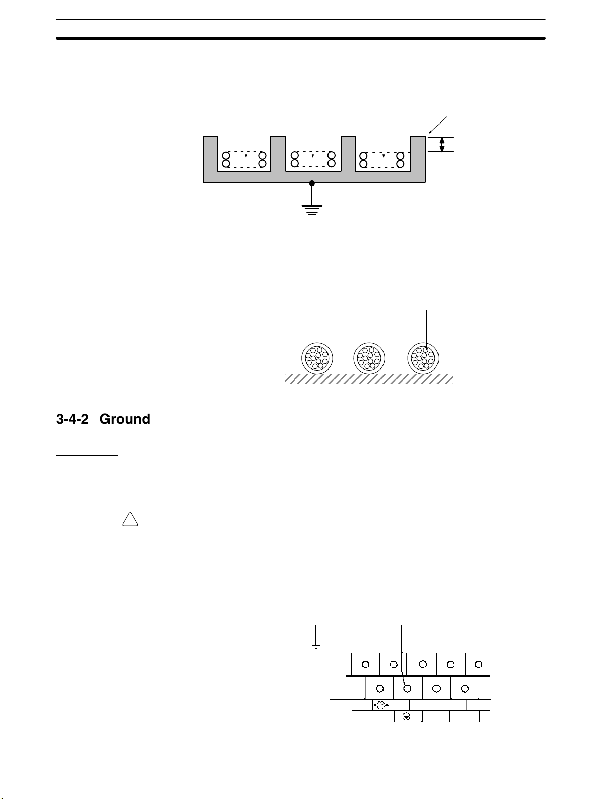
Wiring and Connections
Section 3-4
Floor Ducts
Leave at least 200 mm between the wiring and the top of the duct, as shown in
the following diagram.
CPM1A I/O lines
Control cables and
CPM1A power lines
Power cables
Metal plate (iron)
200 mm min.
Conduits
Separate the CPM1A I/O lines, power and control lines, and power cables, as
shown in the following diagram.
CPM1A I/O lines
Control cables and
CPM1A power lines
Power cables
3-4-2 Ground Wiring
Grounding
WARNING During installation, be sure to ground to 100 Ω max in order to protect against
!
Units with AC Power
Be sure to ground the earth terminal to less than 100 Ω in order to protect against
electric shock and incorrect operation from electrical noise. Be sure to use a wire
2
of at least 1.25 mm
for grounding.
electric shock.
V1 Units
Ground to 100 Ω max.
AC power supply unit
100 to 240 VAC
NC
L2/N
COM
L1
01
00 02
0 CH
51

Wiring and Connections
Section 3-4
Pre-V1 Units
Ground to 100 Ω max.
AC power supply unit
Units with DC Power
!
100 to 240 VAC
L1
L2/N
COM
01
00 02
0 CH
Note Disconnect the functional earth terminal before conducting withstand voltage
test on pre-V1 Units.
Ground to 100 Ω max.
DC power supply unit
24 VDC
+–
NC
COM
01
00 02
0 CH
Note The NC terminal is not used.
Caution Disconnect the functional earth terminal when performing withstand voltage
tests. Not disconnecting the functional earth terminal may result in burning.
Crimp Connectors
Caution Always use crimp connectors for the CPM1A’s power lines and I/O lines or else
!
use a solid wire (instead of a stranded wire). Do not connect bare stranded wires
directly to terminals. Bare stranded wires connected directly to the terminal can
cause a fire.
Use M3 terminal screws and tighten the screws securely (0.5 N m).
The recommended wire size for solid wires is 0.4 to 1.2 mm (AWG26 to AWG18).
3-4-3 Power Supply Wiring
100- to 240-VAC Power
Supply
Wire a separate circuit for the CPM1A’s power supply circuit so that there isn’t a
voltage drop from the inrush current that flows when other equipment is turned
on.
When several CPM1A PCs are being used, it is recommended to wire the PCs
on separate circuits to prevent a voltage drop from the inrush current or incorrect
operation of the circuit breaker.
Use twisted power supply wires to prevent noise from the power supply lines.
Adding a 1:1 isolating transformer reduces electrical noise even further.
Fork terminal Ring terminal
6.2 mm max. 6.2 mm max.
52

Wiring and Connections
Section 3-4
Considering the possibility of voltage drops and the allowable current, be sure to
use thick power lines.
Twist the wires. The cross-sectional area
of each wire must be 1.25 mm
Isolating
transformer
2
min.
Crimp Connectors
AC
power
supply
Breaker
100 to
240 VAC
L2/N
L1
NC
00 02
0 CH
03
01COM
Note 1. Before connecting the power supply, make sure that the CPU Unit requires
an AC power supply and not a DC power supply. The CPU Unit’s internal
circuitry will be damaged if AC power is mistakenly supplied to a CPU Unit
that requires a DC power supply.
2. The power supply input terminals are at the top of the CPU Unit; the terminals at the bottom of the CPU Unit output 24-VDC power for external devices. The CPU Unit’s internal circuitry will be damaged if AC power is mistakenly supplied to a CPU Unit’s power supply output terminals.
Caution Always use crimp connectors for the CPM1A’s power lines. Do not connect bare
!
stranded wires directly to terminals. Bare stranded wires connected directly to
the terminal can cause a fire.
Use M3 terminal screws.
Connect a crimp connector with a ring terminal to each terminal screw.
Ring terminal
6.2 mm max.
Caution Tighten the terminal block screws of the AC Power Supply to the torque of
!
0.5 N m. Loose screws may result in burning or malfunction.
24-VDC Power Supply Use a DC power supply with sufficient capacity and low ripple. For a DC power
supply used for the transistor output, use a power supply with double insulation
or reinforced insulation to conform to the EC Directives (Low-voltage Directives). The NC terminal is not used.
24 VDC
24 VDC
+
NC
COM
–
01
00 02
0 CH
53

Wiring and Connections
Caution Do not perform a withstand voltage test on a CPU Unit with a DC power supply.
!
Crimp Connectors
Caution Always use crimp connectors for the CPM1A’s power lines and I/O lines or else
!
Section 3-4
The test might damage the PC’s internal components.
Note 1. Do not conduct a withstand voltage test for the power supply section of the
CPU Unit with a DC power supply. Doing so may damage internal elements.
2. Reinforced insulation or double insulation must be used for a DC power supply to conform to the EC Directives (Low Voltage Directive).
use a solid wire (instead of a stranded wire). Do not connect bare stranded wires
directly to terminals. Bare stranded wires connected directly to the terminal can
cause a fire.
Use M3 terminal screws and tighten the screws securely (0.5 N m).
Fork terminal Ring terminal
6.2 mm max. 6.2 mm max.
The recommended wire size for solid wires is 0.4 to 1.2 mm (AWG26 to AWG18).
54
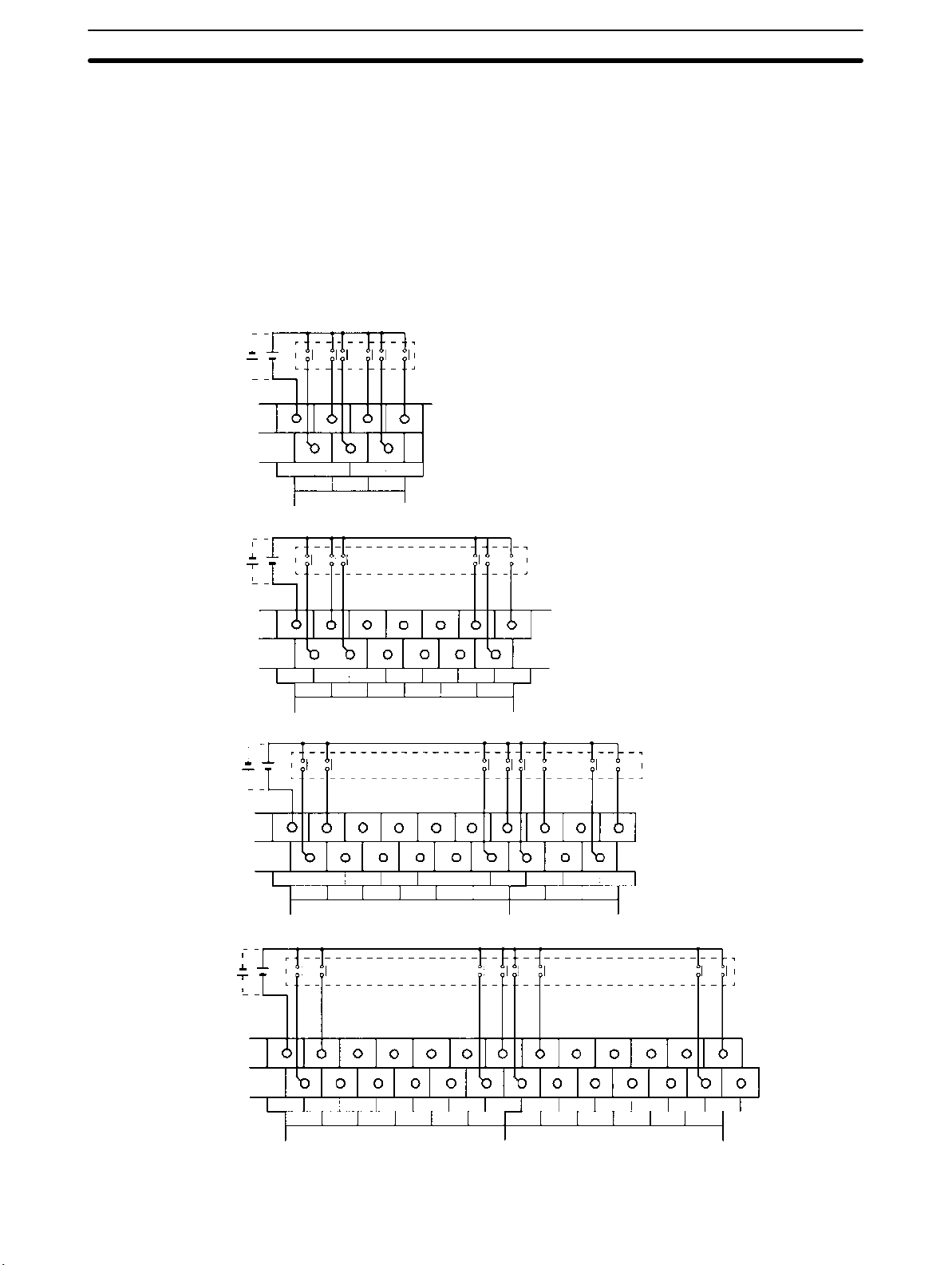
Wiring and Connections
3-4-4 Input Wiring
Wire the inputs to the CPM1A’s CPU Unit and Expansion I/O Unit as shown in the
following diagrams. Use crimp connectors or solid wire (not stranded wire) to
connect to the PC. Do not apply voltages exceeding the rated input voltage to the
input terminals. The power supply output terminals can be used with AC-type
CPU Units.
Input Configuration The following diagrams show the input configurations.
CPM1A-10CDR-(-V1)/10CDT-(-V1)/10CDT1-(-V1)
+10%
24 VDC
/
–15%
COM
00
0 CH
01
03 05
02
04
Input devices
CPM1A-20CDR-(-V1)/20CDT-(-V1)/20CDT1-(-V1)
Section 3-4
24 VDC
24 VDC
24 VDC
+10%
/
–15%
COM
01
03 050807 09
02
04
00
0 CH
06 10
CPM1A-30CDR-(-V1)/30CDT-(-V1)/30CDT1-(-V1)
+10%
/
–15%
COM
01
03 050807 09
02
04
00
0 CH
06 10
CPM1A-40CDR-(-V1)/40CDT-(-V1)/40CDT1-(-V1)
+10%
/
–15%
11
11
00
1 CH
Input devices
01
03 05
02
04
Input devices
Input devices
COM
00
0 CH
01
03 050807 09
02
04
06 10
11
01
00
1 CH
03 050807 09
02
04
06 10
11
55
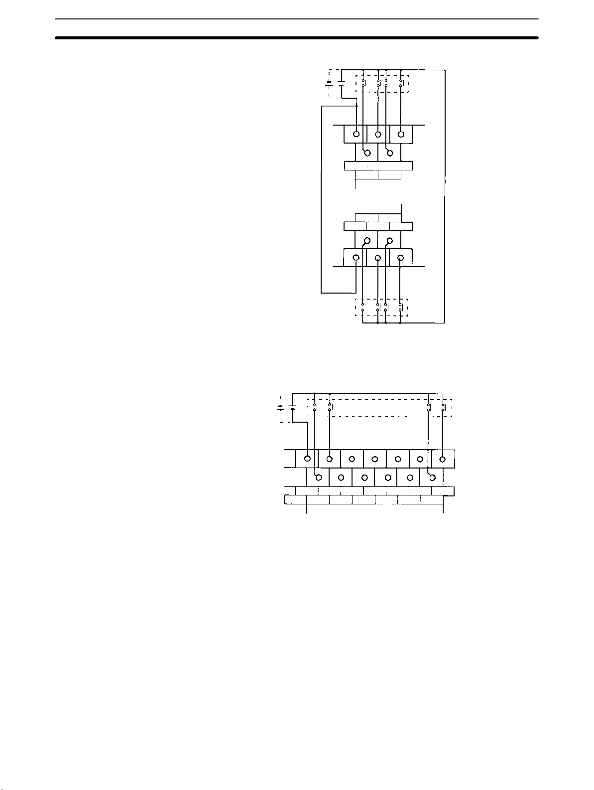
Wiring and Connections
Section 3-4
CPM1A-8ED
24 VDC
COM
010203
00
COM04050607
Input
devices
Input
devices
Note Although the COM terminals are internally connected, be sure to wire them ex-
ternally as well.
CPM1A-20EDR/20EDR1/EDT/EDT1
24 VDC
COM
NC
01
00 02
CH
03 050807 09
04
06 10
Input devices
11
56
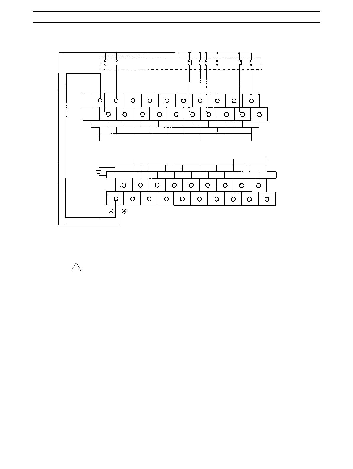
Wiring and Connections
Section 3-4
Input Wiring Example An AC-type CPU Unit is shown. DC-type CPU Units don’t have power supply
outputs.
Input devices
COM
24 VDC at
0.2 A output
COM
00
0 CH
01
03 05
02
04
10 CH 11 CH
+
00 01 02 0504 07 00 02
–
07 09
08
06 10
External power supply:
24 VDC at 200 mA/10-point and 20-point I/O type CPU Units
24 VDC at 300 mA/30-point and 40-point I/O type CPU Units
(Applicable to CPU Units with a power supply of 100 to 240 VAC.)
WARNING When the 24-VDC output (service power supply to the PC) is overloaded or
!
short-circuited, the voltage may drop and result in the outputs being turned OFF.
External safety measures must be provided to ensure safety in the system. Not
providing proper safety measures may result in serious accidents.
11
01
03 05
02
00
1 CH
04
03COM COM COM 03 COM 06 COM
01
57

Wiring and Connections
Input Devices The following table shows how to connect various input devices.
Device Circuit diagram
Relay output
Relay
IN
5 mA/12 mA CPM1A
COM (+)
Section 3-4
NPN open collector
NPN current output
PNP current output
Voltage output
Sensor
Constant current
circuit
+
Output
0 V
+
0 V
+
0 V
+
Output
0 V
Sensor power
supply
5 mA/12 mA
Output
5 mA/12 mA
5 mA/12 mA
Output
Sensor power
supply
+
Sensor power
supply
IN
COM (+)
Use the same power supply for
the input and sensor.
IN
COM (+)
IN
COM (–)
COM (+)
IN
CPM1A
CPM1A
CPM1A
CPM1A
58

Wiring and Connections
Section 3-4
Leakage Current (24 VDC) A leakage current can cause false inputs when using 2-wire sensors (proximity
switches or photoelectric switches) or limit switches with LEDs.
False inputs won’t occur if the leakage current is less than 1.0 mA (2.5 mA for
IN00000 to IN00002), but if the leakage current exceeds these values, insert a
bleeder resistor in the circuit to reduce the input impedance, as shown in the following diagram.
Input power
supply
CPM1A
2-wire sensor, etc.
Bleeder resistor
R
I: Device’s leakage current (mA)
R: Bleeder resistance (kΩ)
W: Bleeder resistor’s power rating (W)
L
5.0
C
R +
I L
The equations above were derived from the following equations:
Input voltage (24)
R
I
W y
Refer to 2-1-3 I/O Specifications for details on the values L
The input impedance, input current, and OFF voltage may vary depending on the
input being used. (IN00000 through IN00002 have different values.)
Input Current (I
Input voltage (24)
R )
Input Current (I
Input voltage (24)
R
kW max. W +
–5.0
C
C
C
Input voltage (24) tolerance (4)
L
: CPM1A’s input impedance (kΩ)
C
: CPM1A’s input current (mA)
I
C
: CPM1A’s OFF voltage (V) = 5.0 V
E
C
2.3
Wmin.
R
)
x OFF voltage (EC:5.0)
)
, IC, and EC.
C
Sensor Surge Current If a sensor power supply is turned ON when the PC is ON and ready to receive
inputs, surge current from the sensor may result in an incorrect input. To prevent
improper operation, use the following type of programming in the ladder program to delay accepting inputs from a sensor from when the sensor is turned ON
until the sensor reaches stable operation.
00000
TIM 0000
#0002
TIM000 00001
01000
00000: Sensor power supply voltage detection
Time required for sensor to stabilize
(for OMRON Proximity Sensor): 100 ms
00001: Input from sensor
Note The SV of TIM 000 can be set to #0001 (0.1 s) to achieve a delay time of 100 ms,
but the timer accuracy is 0 to 0.1 s, meaning that the timer’s Completion Flag
may turn ON immediately after the timer input. The SV must thus be set to #0002
(0.2 s) or higher to allow for timer accuracy.
Inductive Loads When connecting an inductive load to an input, connect a diode in parallel with
the load. The diode should satisfy the following requirements:
1, 2, 3... 1. Peak reverse-breakdown voltage must be at least 3 times the load voltage.
59

Wiring and Connections
Section 3-4
2. Average rectified current must be 1 A.
IN
Crimp Connectors
Diode
Caution Always use crimp connectors for the CPM1A’s power lines and I/O lines or else
!
CPM1A
COM
use a solid wire (instead of a stranded wire). Do not connect bare stranded wires
directly to terminals. Bare stranded wires connected directly to the terminal can
cause a fire.
Use M3 terminal screws and tighten the screws securely (0.5 N m).
Fork terminal Ring terminal
6.2 mm max. 6.2 mm max.
The recommended wire size for solid wires is 0.4 to 1.2 mm (AWG26 to AWG18).
60

Wiring and Connections
3-4-5 Output Wiring
Relay Output Wiring
WARNING The PC outputs may remain ON or OFF due to deposition or burning of the
!
Section 3-4
Wire the outputs to the CPM1A’s CPU Unit and Expansion I/O Unit as shown in
the following diagrams. Use crimp connectors or solid wire (not stranded wire) to
connect to the PC. The power supply output terminals can be used with AC-type
CPU Units.
• Always use solid wire or attach crimp connectors if a stranded wire is used.
• Do not connect loads or apply voltages exceeding the maximum switching ca-
pacity to the output terminals.
• Don’t exceed the output capacity or the maximum common current. Refer to
2-1-3 I/O Specifications for details.
• Each common terminal is separated from one another for each group of output
terminals.
Item Specification
Output capacity 2 A (250 VAC or 24 VDC)
Max. common capacity 4 A/common
output relays or destruction of the output transistors. External safety measures
must be provided to ensure safety in the system. Not providing proper safety
measures may result in serious accidents.
61
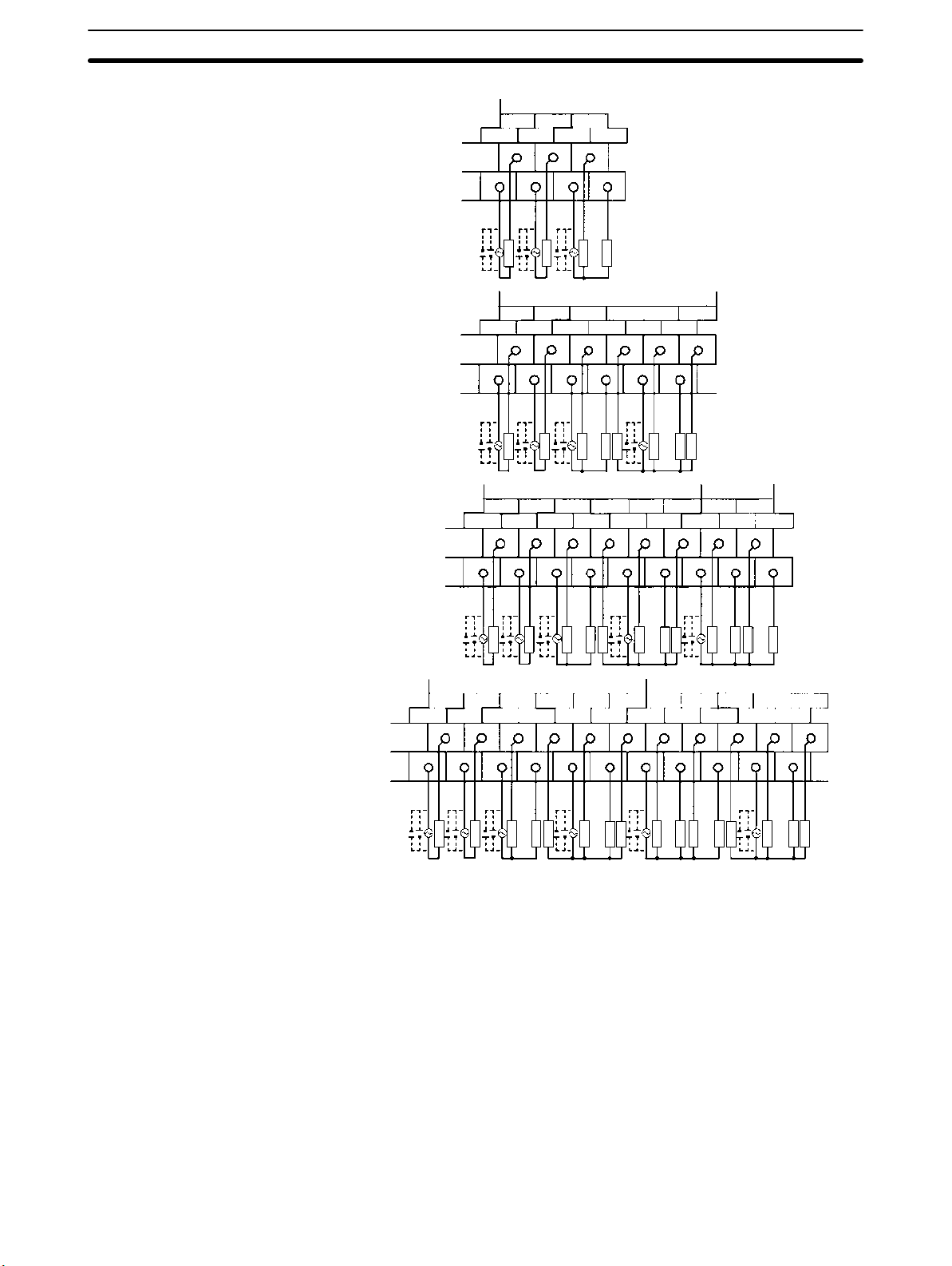
Wiring and Connections
Section 3-4
Output Configurations
CPM1A-10CDR-(-V1)
CPM1A-20CDR-(-V1)/CPM1A-20EDR/20EDR1
CPM1A-30CDR-(-V1)
10 CH
00 01 02
COM COM COM 03
Load
Load
10 CH
Common
00 01 02
COM COM COM 03
Load
Load
10 CH
Common Common
00 01 02
COM COM COM 03
Load
Load
04 05 07
COM 06
Load
Load
Load
04 05 07
Load
Load
Load
11 C H
00
COM06
02
03COM
01
CPM1A-40CDR-(-V1)
Load
10 CH
00 01 02
COM COM COM 03
Load
Load
Load
Common Common Common Common
Load
Common Common Common
04 05 07
Load
Load
Load
Load
Load
Load
Load
Load
Load
11 C H
00
Load
02
01
Load
Load
COM06
Load
Load
Load
Load
Load
04 05 07
03COM
Load
Load
Load
Load
06COM
Load
Load
62

Wiring and Connections
Section 3-4
CPM1A-8ER
250 VAC/
24 VDC
250 VAC/
24 VDC
Load
COM 01
COM 05
Load
Load
Load
Load
0200
0604
Load
Load
03
07
Load
63
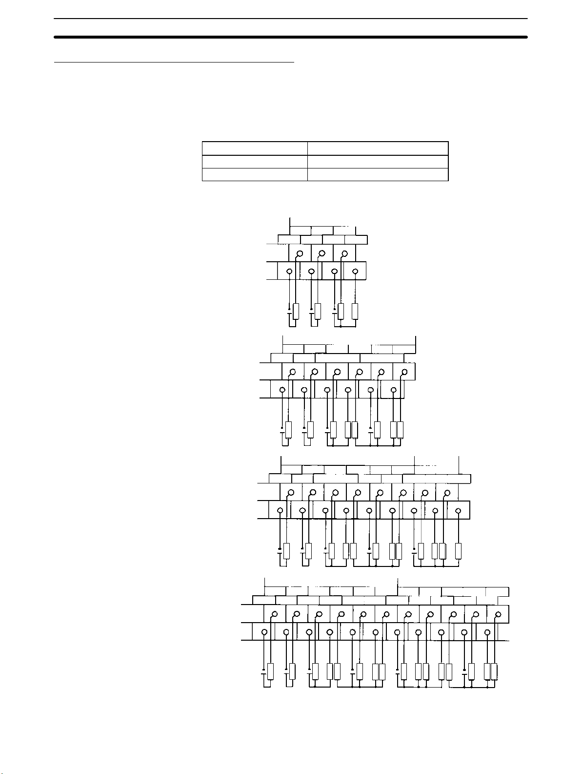
Wiring and Connections
Transistor Output Wiring (Sinking Outputs)
Wire the outputs to the CPM1A’s CPU Unit and Expansion I/O Unit as shown in
the following diagrams.
• Always use solid wire or attach crimp connectors if a stranded wire is used.
• Don’t exceed the output capacity or the maximum common current. Refer to
2-1-3 I/O Specifications for details.
Item Specification
Output capacity 300 mA (24 VDC)
Max. common capacity 0.9 A/common
Section 3-4
Output Configurations
CPM1A-10CDT-(-V1)
CPM1A-20CDT-(-V1)/CPM1A-20EDT
CPM1A-30CDT-(-V1)
24 VDC
24 VDC
+10%
+10%
10 CH
00 01 02
COM COM COM 03
/
/
–15%
–15%
Load
10 CH
00 01 02
COM COM COM 03
Load
10 CH
00 01 02
COM COM COM 03
Load
Load
Load
Common
Load
Load
Load
Load
Common Common
04 05 07
04 05 07
COM 06
Load
Load
Load
11 C H
00
COM06
02
03COM
01
64
CPM1A-40CDT-(-V1)
24 VDC
24 VDC
+10%
+10%
/
–15%
10 CH
00 01 02
COM COM COM 03
/
–15%
Load
Load
Load
Load
Load
Load
Load
Load
Load
Load
Load
Load
Common Common Common
Load
04 05 07
Load
Load
Load
Load
Load
Load
11 C H
00
02
Load
Load
04 05 07
COM06
01 03COM
Load
Load
Common Common Common Common
Load
Load
Load
06COM
Load
Load
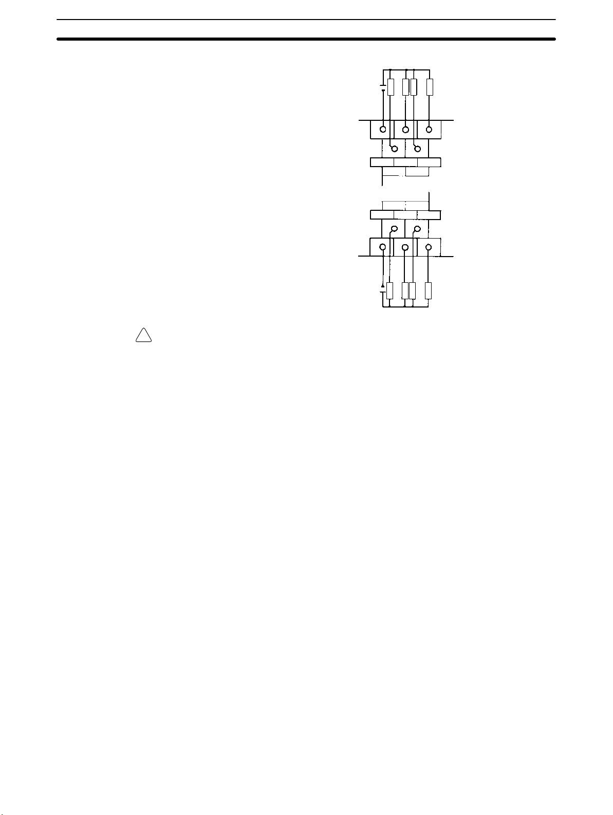
Wiring and Connections
CPM1A-8ET
+10%
24 VDC
/
–15%
Load
Load
Load
Section 3-4
Load
COM 01
COM 05
+10%
24 VDC
Caution Double-check the polarity of the power supply for the load before turning it on.
!
/
–15%
Load
Load
0200
0604
Load
03
07
Load
65

Wiring and Connections
Transistor Output Wiring (Sourcing Outputs)
Wire the outputs to the CPM1A’s CPU Unit and Expansion I/O Unit as shown in
the following diagrams.
• Always use solid wire or attach crimp connectors if a stranded wire is used.
• Don’t exceed the output capacity or the maximum common current. Refer to
2-1-3 I/O Specifications for details.
Item Specification
Output capacity 300 mA (24 VDC)
Max. common capacity 0.9 A/common
Section 3-4
Output Configurations
CPM1A-10CDT1-(-V1)
CPM1A-20CDT1-(-V1)/CPM1A-20EDT1
CPM1A-30CDT1-(-V1)
24 VDC
24 VDC
10 CH
COM COM COM 03
+10%
/
–15%
10 CH
COM COM COM 03
+10%
/
–15%
10 CH
00 01 02
COM COM COM 03
00 01 02
Load
Load
Common
00 01 02
Load
Load
Common Common
Load
Load
04 05 07
COM 06
Load
Load
Load
04 05 07
Load
Load
Load
11 C H
00
COM06
02
03COM
01
66
24 VDC
CPM1A-40CDT1-(-V1)
24 VDC
+10%
+10%
/
–15%
10 CH
00 01 02
COM COM COM 03
/
–15%
Load
Load
Load
Load
Load
Load
Load
Load
Load
Load
Load
Load
Common Common Common
Load
Load
Load
04 05 07
Load
Load
Load
Load
11 C H
00
02
COM06
01
Load
Load
04 05 07
03COM
Load
Load
Load
Common Common Common Common
Load
Load
06COM
Load
Load
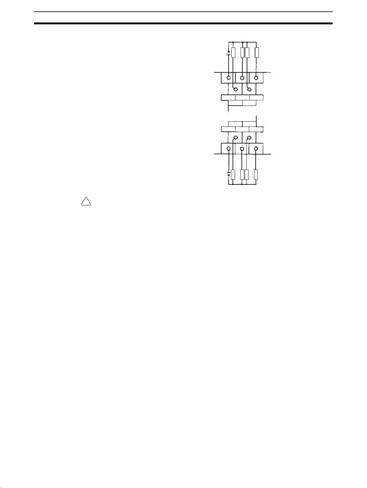
Wiring and Connections
CPM1A-8ET1
+10%
24 VDC
/
–15%
Load
Load
Load
Section 3-4
Load
COM 01
COM 05
+10%
24 VDC
Caution Double-check the polarity of the power supply for the load before turning it on.
!
/
–15%
Load
Load
0200
0604
Load
03
07
Load
Output Wiring Precautions Observe the following precautions to protect the PC’s internal components.
Output Short Protection
The output or internal circuitry might be damaged when the load connected to an
output is short-circuited, so it is recommended to install a protective fuse (0.5 to
1.0 A) in each output circuit.
Polarity of Power Supply for the Load
Double-check the polarity of the DC power supply for the load before wiring the
transistor output. If the polarity of the power supply is reversely connected, the
load will malfunction and internal components may be damaged.
67

Wiring and Connections
Section 3-4
Inductive Loads
When connecting an inductive load to an input, connect a surge protector or
diode in parallel with the load.
The surge protector’s components should have the following ratings:
Relay Output
OUT
Relay Output
Transistor Output
(Sinking Output)
Relay Output
Transistor Output
(Sourcing Output)
CPM1A
COM
OUT
CPM1A
COM
OUT
CPM1A
COM
Surge protector
Diode
Diode
Crimp Connectors
The diode should satisfy the following requirements:
Peak reverse-breakdown voltage must be at least 3 times the load voltage.
Average rectified current must be 1 A.
Inrush Current Considerations
When switching a load with a high inrush current in the CPM1A relay output or
transistor output model, such as an incandescent lamp, suppress the inrush current as shown below.
Countermeasure 1
OUT
R
COM
Providing a dark current of
approx. one-third of the rated
value through an incandescent
lamp
Countermeasure 2
R
OUT
COM
Providing a limiting resistor
Fuse Insertion
The CPM1A with transistor output may burn if the load is short-circuited, therefore, insert a protective fuse in series to the load.
Caution Always use crimp connectors for the CPM1A’s power lines and I/O lines or else
!
use a solid wire (instead of a stranded wire). Do not connect bare stranded wires
directly to terminals. Bare stranded wires connected directly to the terminal can
cause a fire.
68
Use M3 terminal screws and tighten the screws securely (0.5 N m).
Fork terminal Ring terminal
6.2 mm max. 6.2 mm max.
The recommended wire size for solid wires is 0.4 to 1.2 mm (AWG26 to AWG18).
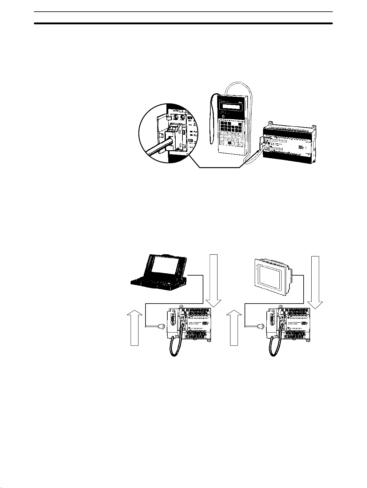
Wiring and Connections
3-4-6 Peripheral Device Connection
The CPM1A CPU Unit can be connected to a C200H-PRO27-E Programming
Console with a standard C200H-CN222 (2 m) or C200H-CN422 (4 m) Connecting Cable. The CPM1A CPU Unit can be also connected to a CQM1-PRO01-E.
The CQM1-PRO01-E is provided with a 2-m Connecting Cable.
3-4-7 Host Link Connections
Host Link is a command/response communications system in which commands
are transmitted from the host computer and corresponding responses are
returned from the destination PCs. Host Link commands can be used to read/
write data in PC data areas and read/write PC settings.
Section 3-4
One-to-one Host Link
Connection
The CPM1A CPU Unit can be connected to an IBM PC/AT compatible computer
or a Programmable Terminal with an RS-232C Adapter, as shown in the following diagram.
OMRON PT
RS-232C
Adapter
Command
CPM1A CPU Unit
RS-232C
Adapter
CPM1A CPU Unit
Command
69
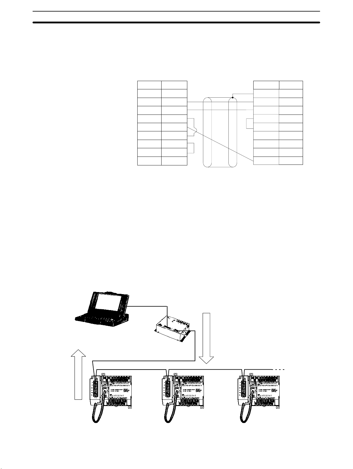
Wiring and Connections
Section 3-4
The following diagram shows the wiring in the RS-232C cable used to connect a
CPM1A to a host computer or Programmable Terminal.
IBM PC/AT compatible computer
or Programmable Terminal (9-pin)
Pin No.Signal
CD
RD
SD
ER
SG
DR
RS
CS
CI
1
2
3
4
5
6
7
8
9
RS-232C Adapter
Pin No. Signal
1/Cover
2
3
4
5
6
7
8
9
9
FG
SD
RD
RS
CS
–
–
–
SG
The type of connector used will vary depending on the PT. Check the PT manual
to ensure the correct connector is used.
Note When the CPM1A is connected to a host computer or OMRON PT, set the
RS-232C Adapter’s mode setting switch to “HOST.”
One-to-N Host Link
Connection
RS-422
Adapter
Up to 32 CPU Units can be connected to an IBM PC/AT compatible computer
with a 3G2A9-AL004-E Link Adapter and RS-422 Adapters, as shown in the following diagram.
RS-232C cable
Link Adapter
RS-422 cable
CPM1A
CPU Unit
3G2A9-AL004-E
RS-422
Adapter
CPM1A
CPU Unit
RS-422
Adapter
CPM1A
CPU Unit
70
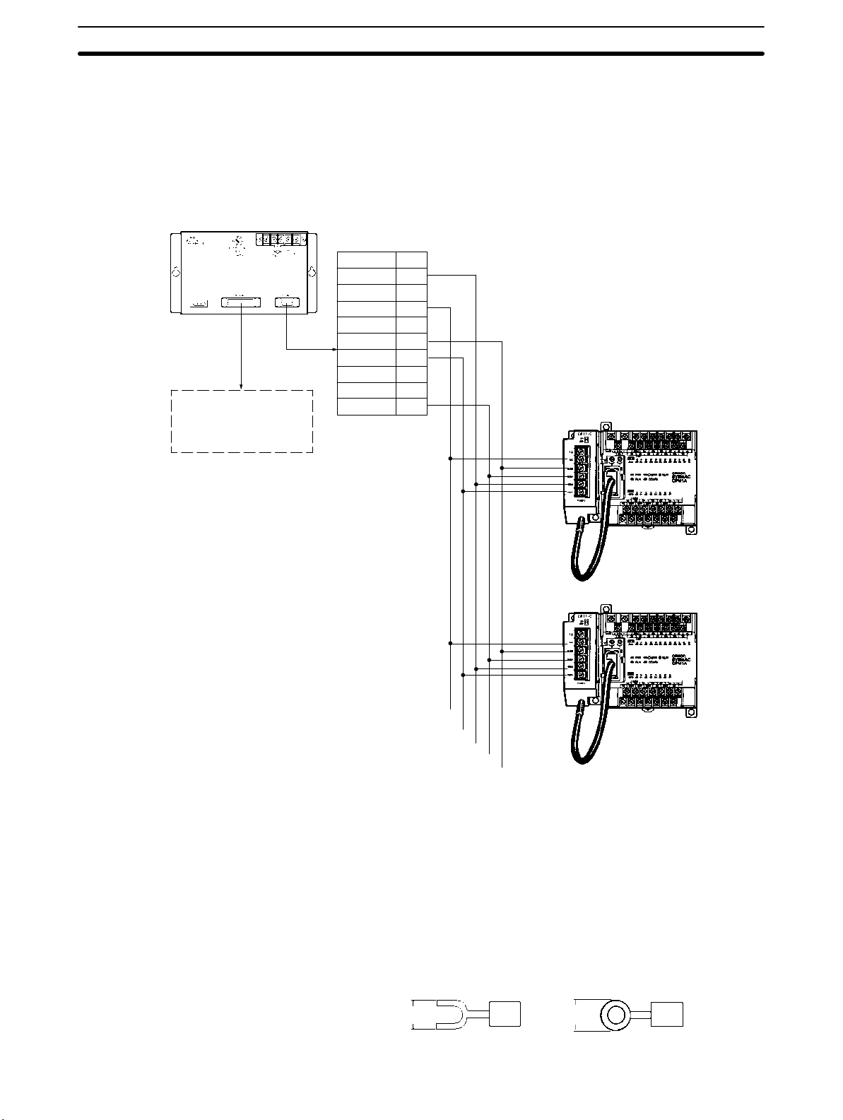
Wiring and Connections
3G2A9-AL004-E Link Adapter
25-pin D-sub Connector
Use a straight RS-232C
cable to connect to the
host computer’s
RS-232C port.
Section 3-4
The following diagram shows the wiring in the RS-422 cables used to connect
CPM1A PCs to a 3G2A9-AL004-E Link Adapter. In both the Link Adapter/
RS-422 Adapter connections and the RS-422 Adapter/RS-422 Adapter connections, connect the SG, RDA, RDB, SDA, and SDB terminals to the same terminals in the other Adapter.
9-pin D-sub Connector
RDB
–
SG
–
SDB
RDA
FG
–
SDA
Pin no.
1
2
3
4
5
6
7
8
9
RS-422 Adapter
CPM1A CPU Unit
Signal
SG
RDA
RDB
SDA
SDB
Note 1. The maximum length of the RS-422 cable should be 500 m.
2. Set the termination resistance switch to “ON” (upper side) for Adapters on
both ends of the Host Link system.
Always use crimp connectors when wiring the RS-422 Adapters. Use M3 terminal screws and tighten the screws securely to the torque of 0.5 N m.
6.2 mm max.
Fork terminal
6.2 mm max.
Ring terminal
71
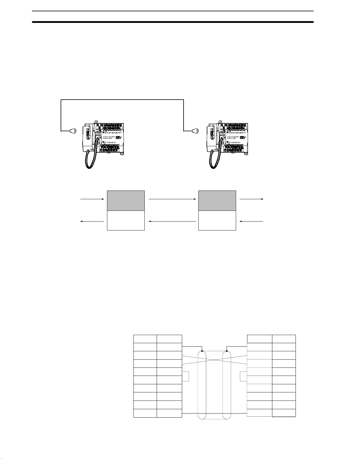
Wiring and Connections
3-4-8 One-to-one PC Link Connections
A CPM1A can be linked to a CPM1A, CQM1, CPM1, CPM2A, CPM2C,
SRM1(-V2), C200HS or C200HX/HG/HE PC through an RS-232C Adapter. One
PC acts as the Master and the other as the Slave to link up to 256 bits in the LR
area (LR 0000 to LR 1515).
RS-232C Cable
Section 3-4
RS-232C Adapter
(see note)
WRITE
READ
RS-232C Adapter
LR 00
LR 07
LR 08
LR 15
CPM1A CPU Unit
Link bits
WRITE area
READ area
(see note)
Link bits
READ area
WRITE area
CPM1A CPU Unit
LR 00
READ
LR 07
LR 08
WRITE
LR 15
Note One-to-one PC connections can only be used when the RS-232C Adapter
(CPM1-CIF01) is connected.
72
Set the DIP switch of the RS-232C Adapter (CPM1-CIF01) to the NT (bottom)
side.
The following diagram shows the wiring in the RS-232C cable used to connect a
CPM1A to another PC.
RS-232C Adapter
Pin No.Signal
FG
SD
RD
RS
CS
–
–
–
SG
1/Cover
2
3
4
5
6
7
8
9
RS-232C Adapter
Pin No. Signal
1/Cover
2
3
4
5
6
7
8
9
9
FG
SD
RD
RS
CS
–
–
–
SG

Wiring and Connections
3-4-9 One-to-one NT Link Connections
High-speed communications can be achieved by providing a direct access
through the use of the 1:1 NT Link between the CPM1A and Programmable Terminal.
Section 3-4
OMRON Programmable Terminal
RS-232C Cable
RS-232C
Adapter
CPM1A CPU Unit
Note The 1:1 NT Link can only be used when the RS-232C Adapter (CPM1-CIF01) is
connected.
Set the DIP switch of the RS-232C Adapter (CPM1-CIF01) to the NT (bottom)
side.
The following diagram shows the wiring in the RS-232C cable used to connect a
CPM1A to a Programmable Terminal.
RS-232C Adapter
Pin No. Signal
1/Cover
2
3
4
5
6
7
8
9
9
FG
SD
RD
RS
CS
–
–
–
SG
–
SD
RD
RS
CS
–
–
–
SG
PT
Pin No.Signal
1
2
3
4
5
6
7
8
9
73
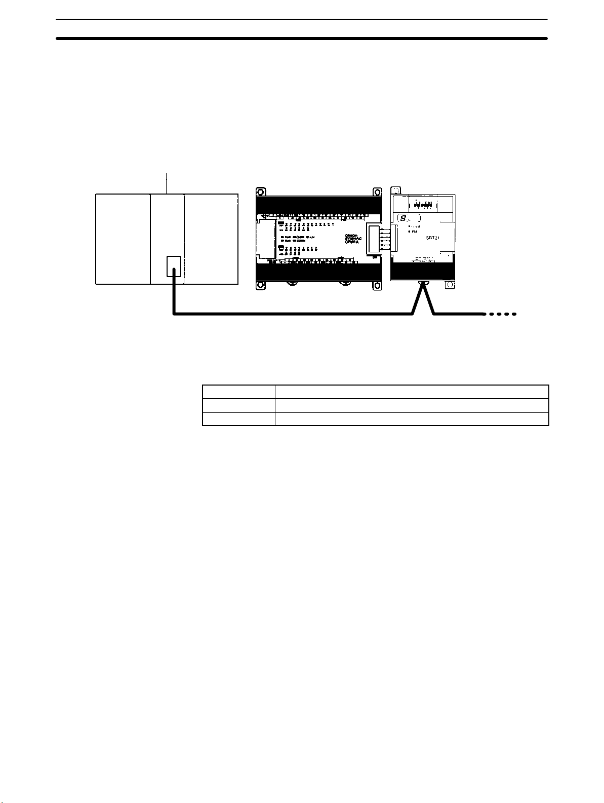
Wiring and Connections
3-4-10 CompoBus/S I/O Link Unit Connections
A CompoBus/S I/O Link Unit can be used to create an I/O link (remote I/O) of 8
input points and 8 output points with a CompoBus/S Master Unit or SRM1 PC.
The connection is made through a CompoBus/S I/O Link Unit.
From the standpoint of the CPM1A CPU Unit, the area allocated to the CompoBus/S I/O Link Unit can be treated just like the area allocated to an Expansion I/O
Unit. The difference is that the bits are not actual I/O points, but I/O bits in the
Master Unit.
Section 3-4
CompoBus/S Master Unit (or SRM1 PC)
C200HX/HG/HE PC
CPM1A CPU Unit
CompoBus/S I/O Link Unit
(Slave)
Cables
Use special flat cable or VCTF cable to connect the nodes in the CompoBus/S
I/O Link. (Special flat cables and VCTF cables cannot be combined in the same
system.)
Name Specifications
Flat cable 4-core flat cable, 0.75 mm
VCTF cable 2-core x 0.75 mm
2
2
74

Wiring and Connections
3-4-11 DeviceNet I/O Link Unit Connections
A DeviceNet I/O Link Unit can be used to create an I/O link (remote I/O) of 32
input points and 32 output points with a DeviceNet master, i.e., the CPM1A operates as a DeviceNet slave.
Up to three DeviceNet I/O Link Units can be connected, for a maximum DeviceNet I/O link capacity of 192 I/O points (96 inputs and 96 outputs). The DeviceNet
I/O Link Unit can be connected only to 30-point or 40-point CPU Units.
CS-series, C200HX/HG/HE(-Z),
CVM1, or CV-series PC
DeviceNet (Master) Unit
DeviceNet transmission path
Section 3-4
DeviceNet slave
Note The current consumption for communications for the DeviceNet I/O Link Unit is
CPM1A CPU Unit
(with 30 or 40 I/O
points)
30 mA.
DeviceNet slave
Remote I/O communications are
possible as a DeviceNet slave
for up to 32 input and 32 output
points for each Unit.
CPM1A-DRT21
DeviceNet I/O Link Unit
(slave)
75

Wiring and Connections
Section 3-4
Network Connection
Connector included with CPM1A-DRT21
(XW4B-05C1-H1-D)
Blue (CAN low)
Connect the DeviceNet I/O Link Unit to the DeviceNet transmission path as
shown in the following diagram.
DeviceNet I/O Link Unit
(CPM1A-DRT21)
Multidrop Connector
(XW4B-05C4-TF-D)
Black (V–)
Shield
White (CAN high)
Red (V+)
DeviceNet Connectors
Use the following DeviceNet connectors.
Model number XW4B-05C1-H1-D XW4B-05C4-TF-D
Specifications OMRON, with set screws,
included with the
CQM1A-DRT21
Appearance
OMRON, multidrop connector
(See note.)
Note Use the XW4B-05C4-TF-D for multidrop wiring of thick cables.
The OMRON XW4Z-00C Screwdriver is available for tightening the line set
screws.
3.5 mm
0.6 mm
76

SECTION 4
Using Peripheral Devices
This section outlines the operations possible with the SYSMAC Support Software (SSS) and the Programming Consoles.
Actual SSS operating procedures are provided in the SSS Operation Manuals: Basics and C-series PCs. Programming Console connection and operating procedures are provided in this section.
4-1 Support Software Capabilities 78. . . . . . . . . . . . . . . . . . . . . . . . . . . . . . . . . . . . . . . . . . . . . . .
4-1-1 SSS System Setup 78. . . . . . . . . . . . . . . . . . . . . . . . . . . . . . . . . . . . . . . . . . . . . . . . .
4-1-2 CPM1A Restrictions and Precautions 78. . . . . . . . . . . . . . . . . . . . . . . . . . . . . . . . . .
4-1-3 Offline Operations 79. . . . . . . . . . . . . . . . . . . . . . . . . . . . . . . . . . . . . . . . . . . . . . . . .
4-1-4 Online Operations 82. . . . . . . . . . . . . . . . . . . . . . . . . . . . . . . . . . . . . . . . . . . . . . . . .
4-1-5 Offline and Online Operations 83. . . . . . . . . . . . . . . . . . . . . . . . . . . . . . . . . . . . . . . .
4-2 Using a Programming Console 84. . . . . . . . . . . . . . . . . . . . . . . . . . . . . . . . . . . . . . . . . . . . . .
4-2-1 Compatible Programming Consoles 84. . . . . . . . . . . . . . . . . . . . . . . . . . . . . . . . . . .
4-2-2 Changing the CPM1A’s Mode with the Mode Switch 86. . . . . . . . . . . . . . . . . . . . . .
4-2-3 Connecting the Programming Console 87. . . . . . . . . . . . . . . . . . . . . . . . . . . . . . . . .
4-2-4 Preparation for Operation 88. . . . . . . . . . . . . . . . . . . . . . . . . . . . . . . . . . . . . . . . . . .
4-2-5 Entering the Password 88. . . . . . . . . . . . . . . . . . . . . . . . . . . . . . . . . . . . . . . . . . . . . .
4-3 Programming Console Operations 90. . . . . . . . . . . . . . . . . . . . . . . . . . . . . . . . . . . . . . . . . . . .
4-3-1 Overview 90. . . . . . . . . . . . . . . . . . . . . . . . . . . . . . . . . . . . . . . . . . . . . . . . . . . . . . . .
4-3-2 Clearing Memory 91. . . . . . . . . . . . . . . . . . . . . . . . . . . . . . . . . . . . . . . . . . . . . . . . . .
4-3-3 Clearing Memory Completely 92. . . . . . . . . . . . . . . . . . . . . . . . . . . . . . . . . . . . . . . .
4-3-4 Reading UM Allocation Information 92. . . . . . . . . . . . . . . . . . . . . . . . . . . . . . . . . . .
4-3-5 Reading/Clearing Error Messages 92. . . . . . . . . . . . . . . . . . . . . . . . . . . . . . . . . . . . .
4-3-6 Buzzer Operation 93. . . . . . . . . . . . . . . . . . . . . . . . . . . . . . . . . . . . . . . . . . . . . . . . . .
4-3-7 Setting and Reading a Program Memory Address and Monitoring I/O Bit Status 94
4-3-8 Entering or Editing Programs 95. . . . . . . . . . . . . . . . . . . . . . . . . . . . . . . . . . . . . . . .
4-3-9 Instruction Search 98. . . . . . . . . . . . . . . . . . . . . . . . . . . . . . . . . . . . . . . . . . . . . . . . .
4-3-10 Bit Operand Search 98. . . . . . . . . . . . . . . . . . . . . . . . . . . . . . . . . . . . . . . . . . . . . . . .
4-3-11 Inserting and Deleting Instructions 99. . . . . . . . . . . . . . . . . . . . . . . . . . . . . . . . . . . .
4-3-12 Checking the Program 100. . . . . . . . . . . . . . . . . . . . . . . . . . . . . . . . . . . . . . . . . . . . . .
4-3-13 Bit, Digit, Word Monitor 101. . . . . . . . . . . . . . . . . . . . . . . . . . . . . . . . . . . . . . . . . . . .
4-3-14 Differentiation Monitor 103. . . . . . . . . . . . . . . . . . . . . . . . . . . . . . . . . . . . . . . . . . . . .
4-3-15 Binary Monitor 103. . . . . . . . . . . . . . . . . . . . . . . . . . . . . . . . . . . . . . . . . . . . . . . . . . .
4-3-16 Three-word Monitor 104. . . . . . . . . . . . . . . . . . . . . . . . . . . . . . . . . . . . . . . . . . . . . . .
4-3-17 Signed Decimal Monitor 105. . . . . . . . . . . . . . . . . . . . . . . . . . . . . . . . . . . . . . . . . . . .
4-3-18 Unsigned Decimal Monitor 105. . . . . . . . . . . . . . . . . . . . . . . . . . . . . . . . . . . . . . . . . .
4-3-19 Three-word Data Modification 106. . . . . . . . . . . . . . . . . . . . . . . . . . . . . . . . . . . . . . .
4-3-20 Changing Timer, Counter SV 106. . . . . . . . . . . . . . . . . . . . . . . . . . . . . . . . . . . . . . . .
4-3-21 Hexadecimal, BCD Data Modification 107. . . . . . . . . . . . . . . . . . . . . . . . . . . . . . . . .
4-3-22 Binary Data Modification 108. . . . . . . . . . . . . . . . . . . . . . . . . . . . . . . . . . . . . . . . . . .
4-3-23 Signed Decimal Data Modification 109. . . . . . . . . . . . . . . . . . . . . . . . . . . . . . . . . . . .
4-3-24 Unsigned Decimal Data Modification 110. . . . . . . . . . . . . . . . . . . . . . . . . . . . . . . . . .
4-3-25 Force Set, Reset 110. . . . . . . . . . . . . . . . . . . . . . . . . . . . . . . . . . . . . . . . . . . . . . . . . . .
4-3-26 Clear Force Set/Reset 111. . . . . . . . . . . . . . . . . . . . . . . . . . . . . . . . . . . . . . . . . . . . . . .
4-3-27 Hex-ASCII Display Change 111. . . . . . . . . . . . . . . . . . . . . . . . . . . . . . . . . . . . . . . . .
4-3-28 Displaying the Cycle Time 112. . . . . . . . . . . . . . . . . . . . . . . . . . . . . . . . . . . . . . . . . .
4-4 Programming Example 112. . . . . . . . . . . . . . . . . . . . . . . . . . . . . . . . . . . . . . . . . . . . . . . . . . . . .
4-4-1 Preparatory Operations 112. . . . . . . . . . . . . . . . . . . . . . . . . . . . . . . . . . . . . . . . . . . . .
4-4-2 Example Program 114. . . . . . . . . . . . . . . . . . . . . . . . . . . . . . . . . . . . . . . . . . . . . . . . .
4-4-3 Programming Procedures 115. . . . . . . . . . . . . . . . . . . . . . . . . . . . . . . . . . . . . . . . . . . .
4-4-4 Checking the Program 118. . . . . . . . . . . . . . . . . . . . . . . . . . . . . . . . . . . . . . . . . . . . . .
4-4-5 Test Run in MONITOR Mode 118. . . . . . . . . . . . . . . . . . . . . . . . . . . . . . . . . . . . . . . .
77
 Loading...