

Page 1

Cat. No. W353-E1-06
SYSMAC
CPM1/CPM1A/CPM2A/CPM2C/SRM1(-V2)
Programmable Controllers
PROGRAMMING MANUAL
Page 2

CPM1/CPM1A/CPM2A/CPM2C/SRM1(-V2)
Programmable Controllers
Programming Manual
Revised February 2008
Page 3

iv
Page 4

Notice:
OMRON products are manufactured for use according to proper procedures by a qualified operator
and only for the purposes described in this manual.
The following conventions are used to indicate and classify precautions in this manual. Always heed
the information provided with them. Failure to heed precautions can result in injury to people or damage to property.
DANGER Indicates an imminently hazardous situation which, if not avoided, will result in death or
!
serious injury.
WARNING Indicates a potentially hazardous situation which, if not avoided, could result in death or
!
serious injury.
Caution Indicates a potentially hazardous situation which, if not avoided, may result in minor or
!
moderate injury, or property damage.
OMRON Product References
All OMRON products are capitalized in this manual. The word “Unit” is also capitalized when it refers
to an OMRON product, regardless of whether or not it appears in the proper name of the product.
The abbreviation “Ch,” which appears in some displays and on some OMRON products, often means
“word” and is abbreviated “Wd” in documentation in this sense.
The abbreviation “PC” means Programmable Controller and is not used as an abbreviation for anything else.
Visual Aids
The following headings appear in the left column of the manual to help you locate different types of
information.
OMRON, 1999
All rights reserved. No part of this publication may be reproduced, stored in a retrieval system, or transmitted, in any
form, or by any means, mechanical, electronic, photocopying, recording, or otherwise, without the prior written permission of OMRON.
No patent liability is assumed with respect to the use of the information contained herein. Moreover, because OMRON is
constantly striving to improve its high-quality products, the information contained in this manual is subject to change
without notice. Every precaution has been taken in the preparation of this manual. Nevertheless, OMRON assumes no
responsibility for errors or omissions. Neither is any liability assumed for damages resulting from the use of the information contained in this publication.
Note Indicates information of particular interest for efficient and convenient operation
of the product.
1, 2, 3... 1. Indicates lists of one sort or another, such as procedures, checklists, etc.
v
Page 5

vi
Page 6

TABLE OF CONTENTS
PRECAUTIONS xvii. . . . . . . . . . . . . . . . . . . . . . . . . . . . . . . . .
1 Intended Audience xviii. . . . . . . . . . . . . . . . . . . . . . . . . . . . . . . . . . . . . . . . . . . . . . . . . . . . . . . . . . .
2 General Precautions xviii. . . . . . . . . . . . . . . . . . . . . . . . . . . . . . . . . . . . . . . . . . . . . . . . . . . . . . . . . .
3 Safety Precautions xviii. . . . . . . . . . . . . . . . . . . . . . . . . . . . . . . . . . . . . . . . . . . . . . . . . . . . . . . . . . .
4 Operating Environment Precautions xx. . . . . . . . . . . . . . . . . . . . . . . . . . . . . . . . . . . . . . . . . . . . .
5 Application Precautions xxi. . . . . . . . . . . . . . . . . . . . . . . . . . . . . . . . . . . . . . . . . . . . . . . . . . . . . .
SECTION 1
PC Setup 1. . . . . . . . . . . . . . . . . . . . . . . . . . . . . . . . . . . . . . .
1-1 PC Setup 2. . . . . . . . . . . . . . . . . . . . . . . . . . . . . . . . . . . . . . . . . . . . . . . . . . . . . . . . . . . . . . .
1-2 Basic PC Operation and I/O Processes 16. . . . . . . . . . . . . . . . . . . . . . . . . . . . . . . . . . . . . . .
1-3 CPM2C Changes in SW2 21. . . . . . . . . . . . . . . . . . . . . . . . . . . . . . . . . . . . . . . . . . . . . . . . . .
SECTION 2
Special Features 25. . . . . . . . . . . . . . . . . . . . . . . . . . . . . . . . .
2-1 CPM2A/CPM2C Interrupt Functions 26. . . . . . . . . . . . . . . . . . . . . . . . . . . . . . . . . . . . . . . . .
2-2 CPM2A/CPM2C High-speed Counters 45. . . . . . . . . . . . . . . . . . . . . . . . . . . . . . . . . . . . . . .
2-3 CPM1/CPM1A Interrupt Functions 77. . . . . . . . . . . . . . . . . . . . . . . . . . . . . . . . . . . . . . . . . .
2-4 SRM1(-V2) Interrupt Functions 94. . . . . . . . . . . . . . . . . . . . . . . . . . . . . . . . . . . . . . . . . . . . .
2-5 CPM2A/CPM2C Pulse Output Functions 97. . . . . . . . . . . . . . . . . . . . . . . . . . . . . . . . . . . . .
2-6 CPM1A Pulse Output Functions 131. . . . . . . . . . . . . . . . . . . . . . . . . . . . . . . . . . . . . . . . . . . .
2-7 Synchronized Pulse Control (CPM2A/CPM2C Only) 134. . . . . . . . . . . . . . . . . . . . . . . . . . . .
2-8 Data Computation Standards 146. . . . . . . . . . . . . . . . . . . . . . . . . . . . . . . . . . . . . . . . . . . . . . .
2-9 Analog I/O Functions (CPM1/CPM1A/CPM2A/CPM2C Only) 147. . . . . . . . . . . . . . . . . . . .
2-10 Temperature Sensor Input Functions (CPM1A/CPM2A/CPM2C Only) 147. . . . . . . . . . . . . .
2-11 CompoBus/S I/O Slave Functions (CPM1A/CPM2A/CPM2C Only) 147. . . . . . . . . . . . . . . .
2-12 CompoBus/S I/O Master Functions (SRM1(-V2) and CPM2C-S Only) 148. . . . . . . . . . . . . .
2-13 Analog Controls (CPM1/CPM1A/CPM2A Only) 150. . . . . . . . . . . . . . . . . . . . . . . . . . . . . . .
2-14 Quick-response Inputs 153. . . . . . . . . . . . . . . . . . . . . . . . . . . . . . . . . . . . . . . . . . . . . . . . . . . .
2-15 Macro Function 157. . . . . . . . . . . . . . . . . . . . . . . . . . . . . . . . . . . . . . . . . . . . . . . . . . . . . . . . .
2-16 Calculating with Signed Binary Data 158. . . . . . . . . . . . . . . . . . . . . . . . . . . . . . . . . . . . . . . .
2-17 Differential Monitor 159. . . . . . . . . . . . . . . . . . . . . . . . . . . . . . . . . . . . . . . . . . . . . . . . . . . . . .
2-18 Expansion Instructions (CPM2A/CPM2C/SRM1(-V2) Only) 160. . . . . . . . . . . . . . . . . . . . . .
2-19 Using the CPM2A/CPM2C Clock Function 163. . . . . . . . . . . . . . . . . . . . . . . . . . . . . . . . . . .
SECTION 3
Using Expansion Units 165. . . . . . . . . . . . . . . . . . . . . . . . . . . .
3-1 Analog I/O Units 166. . . . . . . . . . . . . . . . . . . . . . . . . . . . . . . . . . . . . . . . . . . . . . . . . . . . . . . .
3-2 Temperature Sensor Units 193. . . . . . . . . . . . . . . . . . . . . . . . . . . . . . . . . . . . . . . . . . . . . . . . .
3-3 CompoBus/S I/O Link Units 214. . . . . . . . . . . . . . . . . . . . . . . . . . . . . . . . . . . . . . . . . . . . . . .
3-4 DeviceNet I/O Link Unit 219. . . . . . . . . . . . . . . . . . . . . . . . . . . . . . . . . . . . . . . . . . . . . . . . . .
SECTION 4
Communications Functions 225. . . . . . . . . . . . . . . . . . . . . . . .
4-1 Introduction 226. . . . . . . . . . . . . . . . . . . . . . . . . . . . . . . . . . . . . . . . . . . . . . . . . . . . . . . . . . . .
4-2 CPM1/CPM1A Communications Functions 227. . . . . . . . . . . . . . . . . . . . . . . . . . . . . . . . . . .
4-3 CPM2A/CPM2C Communications Functions 231. . . . . . . . . . . . . . . . . . . . . . . . . . . . . . . . . .
4-4 SRM1(-V2) Communications Functions 268. . . . . . . . . . . . . . . . . . . . . . . . . . . . . . . . . . . . . .
4-5 Host Link Commands 281. . . . . . . . . . . . . . . . . . . . . . . . . . . . . . . . . . . . . . . . . . . . . . . . . . . . .
SECTION 5
Memory Areas 307. . . . . . . . . . . . . . . . . . . . . . . . . . . . . . . . . .
5-1 Memory Area Functions 308. . . . . . . . . . . . . . . . . . . . . . . . . . . . . . . . . . . . . . . . . . . . . . . . . . .
5-2 I/O Allocation for CPM1/CPM1A/CPM2A PCs 313. . . . . . . . . . . . . . . . . . . . . . . . . . . . . . . .
5-3 I/O Allocation for CPM2C PCs 323. . . . . . . . . . . . . . . . . . . . . . . . . . . . . . . . . . . . . . . . . . . . .
vii
Page 7

SECTION 6
Ladder-diagram Programming 333. . . . . . . . . . . . . . . . . . . .
6-1 Basic Procedure 334. . . . . . . . . . . . . . . . . . . . . . . . . . . . . . . . . . . . . . . . . . . . . . . . . . . . . . . . .
6-2 Instruction Terminology 334. . . . . . . . . . . . . . . . . . . . . . . . . . . . . . . . . . . . . . . . . . . . . . . . . . .
6-3 Basic Ladder Diagrams 335. . . . . . . . . . . . . . . . . . . . . . . . . . . . . . . . . . . . . . . . . . . . . . . . . . .
6-4 Controlling Bit Status 354. . . . . . . . . . . . . . . . . . . . . . . . . . . . . . . . . . . . . . . . . . . . . . . . . . . . .
6-5 Work Bits (Internal Relays) 356. . . . . . . . . . . . . . . . . . . . . . . . . . . . . . . . . . . . . . . . . . . . . . . .
6-6 Programming Precautions 358. . . . . . . . . . . . . . . . . . . . . . . . . . . . . . . . . . . . . . . . . . . . . . . . .
6-7 Program Execution 360. . . . . . . . . . . . . . . . . . . . . . . . . . . . . . . . . . . . . . . . . . . . . . . . . . . . . . .
SECTION 7
Instruction Set 361. . . . . . . . . . . . . . . . . . . . . . . . . . . . . . . . . .
7-1 Notation 364. . . . . . . . . . . . . . . . . . . . . . . . . . . . . . . . . . . . . . . . . . . . . . . . . . . . . . . . . . . . . . .
7-2 Instruction Format 364. . . . . . . . . . . . . . . . . . . . . . . . . . . . . . . . . . . . . . . . . . . . . . . . . . . . . . .
7-3 Data Areas, Definer Values, and Flags 364. . . . . . . . . . . . . . . . . . . . . . . . . . . . . . . . . . . . . . .
7-4 Differentiated Instructions 366. . . . . . . . . . . . . . . . . . . . . . . . . . . . . . . . . . . . . . . . . . . . . . . . .
7-5 Coding Right-hand Instructions 367. . . . . . . . . . . . . . . . . . . . . . . . . . . . . . . . . . . . . . . . . . . . .
7-6 Instruction Tables 370. . . . . . . . . . . . . . . . . . . . . . . . . . . . . . . . . . . . . . . . . . . . . . . . . . . . . . . .
7-7 Ladder Diagram Instructions 376. . . . . . . . . . . . . . . . . . . . . . . . . . . . . . . . . . . . . . . . . . . . . . .
7-8 Bit Control Instructions 377. . . . . . . . . . . . . . . . . . . . . . . . . . . . . . . . . . . . . . . . . . . . . . . . . . .
7-9 NO OPERATION – NOP(00) 381. . . . . . . . . . . . . . . . . . . . . . . . . . . . . . . . . . . . . . . . . . . . . . .
7-10 END – END(01) 381. . . . . . . . . . . . . . . . . . . . . . . . . . . . . . . . . . . . . . . . . . . . . . . . . . . . . . . .
7-11 INTERLOCK and INTERLOCK CLEAR – IL(02) and ILC(03) 381. . . . . . . . . . . . . . . . . . .
7-12 JUMP and JUMP END – JMP(04) and JME(05) 383. . . . . . . . . . . . . . . . . . . . . . . . . . . . . . . .
7-13 User Error Instructions:
FAILURE ALARM AND RESET – FAL(06) and
SEVERE FAILURE ALARM – FALS(07) 385. . . . . . . . . . . . . . . . . . . . . . . . . . . . . . . . . . . .
7-14 Step Instructions:
STEP DEFINE and STEP START–STEP(08)/SNXT(09) 385. . . . . . . . . . . . . . . . . . . . . . . . .
7-15 Timer and Counter Instructions 388. . . . . . . . . . . . . . . . . . . . . . . . . . . . . . . . . . . . . . . . . . . . .
7-16 Shift Instructions 404. . . . . . . . . . . . . . . . . . . . . . . . . . . . . . . . . . . . . . . . . . . . . . . . . . . . . . . .
7-17 Data Movement Instructions 411. . . . . . . . . . . . . . . . . . . . . . . . . . . . . . . . . . . . . . . . . . . . . . .
7-18 Data Control Instructions 421. . . . . . . . . . . . . . . . . . . . . . . . . . . . . . . . . . . . . . . . . . . . . . . . . .
7-19 Comparison Instructions 432. . . . . . . . . . . . . . . . . . . . . . . . . . . . . . . . . . . . . . . . . . . . . . . . . .
7-20 Conversion Instructions 439. . . . . . . . . . . . . . . . . . . . . . . . . . . . . . . . . . . . . . . . . . . . . . . . . . .
7-21 BCD Calculation Instructions 457. . . . . . . . . . . . . . . . . . . . . . . . . . . . . . . . . . . . . . . . . . . . . .
7-22 Binary Calculation Instructions 467. . . . . . . . . . . . . . . . . . . . . . . . . . . . . . . . . . . . . . . . . . . . .
7-23 Special Math Instructions 471. . . . . . . . . . . . . . . . . . . . . . . . . . . . . . . . . . . . . . . . . . . . . . . . . .
7-24 Logic Instructions 479. . . . . . . . . . . . . . . . . . . . . . . . . . . . . . . . . . . . . . . . . . . . . . . . . . . . . . . .
7-25 Increment/Decrement Instructions 483. . . . . . . . . . . . . . . . . . . . . . . . . . . . . . . . . . . . . . . . . . .
7-26 Subroutine Instructions 484. . . . . . . . . . . . . . . . . . . . . . . . . . . . . . . . . . . . . . . . . . . . . . . . . . .
7-27 Pulse Output Instructions 487. . . . . . . . . . . . . . . . . . . . . . . . . . . . . . . . . . . . . . . . . . . . . . . . . .
7-28 Special Instructions 497. . . . . . . . . . . . . . . . . . . . . . . . . . . . . . . . . . . . . . . . . . . . . . . . . . . . . .
7-29 Interrupt Control Instructions 501. . . . . . . . . . . . . . . . . . . . . . . . . . . . . . . . . . . . . . . . . . . . . . .
7-30 Communications Instructions 505. . . . . . . . . . . . . . . . . . . . . . . . . . . . . . . . . . . . . . . . . . . . . . .
SECTION 8
PC Operations and Processing Time 511. . . . . . . . . . . . . . . .
8-1 CPM1/CPM1A Cycle Time and I/O Response Time 512. . . . . . . . . . . . . . . . . . . . . . . . . . . .
8-2 CPM2A/CPM2C Cycle Time and I/O Response Time 523. . . . . . . . . . . . . . . . . . . . . . . . . . .
8-3 SRM1(-V2) Cycle Time and I/O Response Time 537. . . . . . . . . . . . . . . . . . . . . . . . . . . . . . .
viii
Page 8

TABLE OF CONTENTS
SECTION 9
Troubleshooting 549. . . . . . . . . . . . . . . . . . . . . . . . . . . . . . . . .
9-1 Introduction 550. . . . . . . . . . . . . . . . . . . . . . . . . . . . . . . . . . . . . . . . . . . . . . . . . . . . . . . . . . . .
9-2 Programming Console Operation Errors 550. . . . . . . . . . . . . . . . . . . . . . . . . . . . . . . . . . . . . .
9-3 Programming Errors 551. . . . . . . . . . . . . . . . . . . . . . . . . . . . . . . . . . . . . . . . . . . . . . . . . . . . . .
9-4 User-defined Errors 552. . . . . . . . . . . . . . . . . . . . . . . . . . . . . . . . . . . . . . . . . . . . . . . . . . . . . .
9-5 Operating Errors 553. . . . . . . . . . . . . . . . . . . . . . . . . . . . . . . . . . . . . . . . . . . . . . . . . . . . . . . . .
9-6 Error Log 555. . . . . . . . . . . . . . . . . . . . . . . . . . . . . . . . . . . . . . . . . . . . . . . . . . . . . . . . . . . . . .
9-7 Host Link Errors 557. . . . . . . . . . . . . . . . . . . . . . . . . . . . . . . . . . . . . . . . . . . . . . . . . . . . . . . . .
9-8 Troubleshooting Flowcharts 557. . . . . . . . . . . . . . . . . . . . . . . . . . . . . . . . . . . . . . . . . . . . . . . .
Appendices
A Programming Instructions 559. . . . . . . . . . . . . . . . . . . . . . . . . . . . . . . . . . . . . . . . . . . . . . . . . . . .
B Error and Arithmetic Flag Operation 565. . . . . . . . . . . . . . . . . . . . . . . . . . . . . . . . . . . . . . . . . . . .
C Memory Areas 569. . . . . . . . . . . . . . . . . . . . . . . . . . . . . . . . . . . . . . . . . . . . . . . . . . . . . . . . . . . . .
D I/O Assignment Sheet 587. . . . . . . . . . . . . . . . . . . . . . . . . . . . . . . . . . . . . . . . . . . . . . . . . . . . . . .
E Program Coding Sheet 589. . . . . . . . . . . . . . . . . . . . . . . . . . . . . . . . . . . . . . . . . . . . . . . . . . . . . . .
F List of FAL Numbers 593. . . . . . . . . . . . . . . . . . . . . . . . . . . . . . . . . . . . . . . . . . . . . . . . . . . . . . . .
G Extended ASCII 595. . . . . . . . . . . . . . . . . . . . . . . . . . . . . . . . . . . . . . . . . . . . . . . . . . . . . . . . . . . .
Index 597. . . . . . . . . . . . . . . . . . . . . . . . . . . . . . . . . . . . . . . . . .
Revision History 603. . . . . . . . . . . . . . . . . . . . . . . . . . . . . . . . .
ix
Page 9

x
Page 10

About this Manual:
gp
This manual provides information on programming the CPM1, CPM1A, CPM2A, CPM2C (including the
CPM2C-S), and SRM1(-V2) PCs. The following manuals describe the system configurations and installation of the PCs and provide a basic explanation of operating procedures for the Programming Consoles.
Read the relevant manual first to acquaint yourself with the PC.
Manual Catalog No.
CPM1 Operation Manual W262
CPM1A Operation Manual W317
CPM2A Operation Manual W352
CPM2C Operation Manual W356
CPM2C-S Operation Manual W377
SRM1(-V2) Operation Manual W318
Note 1. Version 2 (-V2) of the SRM1 is included beginning with following revision of the manual:
W318-E1-3.
2. Refer to sections on the CPM2C for information on CPM2C instructions and Expansion
Units.
For programming the CPM1, CPM1A, CPM2A, CPM2C (including the CPM2C-S), and SRM1(-V2) PCs,
use the CX-Programmer, special Support Software that runs in a Windows environment. The SYSMAC
Support Software and SYSMAC-CPT Support Software can also be used. Please refer to the relevant
manuals listed in the following table when using any one of Support Software.
Name Model No. Manual Catalog
No.
CX-Programmer version 3.1 WS02-CXPC1-EV3
CX-Programmer version 4.0 WS02-CXPC1-EV4
SYSMAC Support Software C500-ZL3AT1-E
SYSMAC-CPT Support Software WS02-CPTB1-E
CX-Programmer Operation Manual
SYSMAC Support Software
Operation Manual: Basic
SYSMAC Support Software
Operation Manual: C-series PCs
SYSMAC-CPT Support Software Quick
Start Guide
SYSMAC-CPT Support Software
User Manual
W414
W425
W247
W248
W332
W333
Please read this manual carefully and be sure you understand the information provided before attempting
to program or operate the PC.
Section 1 explains the PC Setup. The PC Setup can be used to control the operating parameters.
Section 2 explains special features of the PC.
Section 3 describes how to use the CPM1A-MAD01 and CPM2C-MAD11 Analog I/O Units, the CPM1A-
TS and CPM2C-TS Temperature Sensor Units, and the CPM1A-SRT21 and CPM2C-SRT21
CompoBus/S I/O Link Units.
!
WARNING Failure to read and understand the information provided in this manual may result in
personal injury or death, damage to the product, or product failure. Please read each
section in its entirety and be sure you understand the information provided in the section
and related sections before attempting any of the procedures or operations given.
xi
Page 11

About this Manual, Continued
Section 4 describes how to use the communications functions provided in the PCs.
Section 5 describes the structure of the PC memory areas and explains how to use them. Details of some
areas are provided in Appendix C.
Section 6 explains the basic steps and concepts involved in writing a basic ladder diagram program. It
introduces the instructions that are used to build the basic structure of the ladder diagram and control its
execution.
Section 7 explains instructions individually and provides the ladder diagram symbol, data areas, and
flags used with each.
Section 8 explains the internal PC processing, as well as the time required for processing and execution.
Section 9 describes how to diagnose and correct hardware and software errors that can occur during
operation.
Various Appendices are also provided for easy reference. Refer to the table of contents for a list of appendices.
xii
Page 12
Read and Understand this Manual
Á
Á
Á
Á
Á
Á
Á
Á
Á
Á
Á
Á
Á
Á
Á
Please read and understand this manual before using the product. Please consult your OMRON
representative if you have any questions or comments.
Warranty and Limitations of Liability
WARRANTY
OMRON’s exclusive warranty is that the products are free from defects in materials and workmanship for
БББББББББББББББББББББББББББББББ
a period of one year (or other period if specified) from date of sale by OMRON.
БББББББББББББББББББББББББББББББ
OMRON MAKES NO WARRANTY OR REPRESENTATION, EXPRESS OR IMPLIED, REGARDING
БББББББББББББББББББББББББББББББ
NON–INFRINGEMENT, MERCHANTABILITY, OR FITNESS FOR PARTICULAR PURPOSE OF THE
БББББББББББББББББББББББББББББББ
PRODUCTS. ANY BUYER OR USER ACKNOWLEDGES THAT THE BUYER OR USER ALONE HAS
БББББББББББББББББББББББББББББББ
DETERMINED THAT THE PRODUCTS WILL SUITABLY MEET THE REQUIREMENTS OF THEIR
INTENDED USE. OMRON DISCLAIMS ALL OTHER WARRANTIES, EXPRESS OR IMPLIED.
БББББББББББББББББББББББББББББББ
БББББББББББББББББББББББББББББББ
LIMITATIONS OF LIABILITY
OMRON SHALL NOT BE RESPONSIBLE FOR SPECIAL, INDIRECT, OR CONSEQUENTIAL
DAMAGES, LOSS OF PROFITS OR COMMERCIAL LOSS IN ANY WAY CONNECTED WITH THE
БББББББББББББББББББББББББББББББ
PRODUCTS, WHETHER SUCH CLAIM IS BASED ON CONTRACT, WARRANTY, NEGLIGENCE, OR
БББББББББББББББББББББББББББББББ
STRICT LIABILITY.
БББББББББББББББББББББББББББББББ
In no event shall the responsibility of OMRON for any act exceed the individual price of the product on
БББББББББББББББББББББББББББББББ
which liability is asserted.
БББББББББББББББББББББББББББББББ
IN NO EVENT SHALL OMRON BE RESPONSIBLE FOR WARRANTY, REPAIR, OR OTHER CLAIMS
БББББББББББББББББББББББББББББББ
REGARDING THE PRODUCTS UNLESS OMRON’S ANALYSIS CONFIRMS THAT THE PRODUCTS
БББББББББББББББББББББББББББББББ
WERE PROPERLY HANDLED, STORED, INSTALLED, AND MAINTAINED AND NOT SUBJECT TO
БББББББББББББББББББББББББББББББ
CONTAMINATION, ABUSE, MISUSE, OR INAPPROPRIATE MODIFICATION OR REPAIR.
xiii
Page 13
Application Considerations
Á
Á
Á
Á
Á
Á
Á
Á
Á
Á
Á
Á
Á
Á
Á
Á
Á
Á
Á
Á
Á
Á
SUITABILITY FOR USE
OMRON shall not be responsible for conformity with any standards, codes, or regulations that apply to
БББББББББББББББББББББББББББББББ
the combination of products in the customer’s application or use of the products.
БББББББББББББББББББББББББББББББ
At the customer’s request, OMRON will provide applicable third party certification documents identifying
БББББББББББББББББББББББББББББББ
ratings and limitations of use that apply to the products. This information by itself is not sufficient for a
БББББББББББББББББББББББББББББББ
complete determination of the suitability of the products in combination with the end product, machine,
БББББББББББББББББББББББББББББББ
system, or other application or use.
БББББББББББББББББББББББББББББББ
The following are some examples of applications for which particular attention must be given. This is not
БББББББББББББББББББББББББББББББ
intended to be an exhaustive list of all possible uses of the products, nor is it intended to imply that the
БББББББББББББББББББББББББББББББ
uses listed may be suitable for the products:
БББББББББББББББББББББББББББББББ
• Outdoor use, uses involving potential chemical contamination or electrical interference, or conditions
БББББББББББББББББББББББББББББББ
or uses not described in this manual.
БББББББББББББББББББББББББББББББ
• Nuclear energy control systems, combustion systems, railroad systems, aviation systems, medical
БББББББББББББББББББББББББББББББ
equipment, amusement machines, vehicles, safety equipment, and installations subject to separate
БББББББББББББББББББББББББББББББ
industry or government regulations.
БББББББББББББББББББББББББББББББ
• Systems, machines, and equipment that could present a risk to life or property.
БББББББББББББББББББББББББББББББ
Please know and observe all prohibitions of use applicable to the products.
БББББББББББББББББББББББББББББББ
БББББББББББББББББББББББББББББББ
NEVER USE THE PRODUCTS FOR AN APPLICATION INVOLVING SERIOUS RISK TO LIFE OR
БББББББББББББББББББББББББББББББ
PROPERTY WITHOUT ENSURING THAT THE SYSTEM AS A WHOLE HAS BEEN DESIGNED TO
ADDRESS THE RISKS, AND THAT THE OMRON PRODUCTS ARE PROPERLY RATED AND
БББББББББББББББББББББББББББББББ
INSTALLED FOR THE INTENDED USE WITHIN THE OVERALL EQUIPMENT OR SYSTEM.
БББББББББББББББББББББББББББББББ
БББББББББББББББББББББББББББББББ
PROGRAMMABLE PRODUCTS
OMRON shall not be responsible for the user’s programming of a programmable product, or any
БББББББББББББББББББББББББББББББ
consequence thereof.
xiv
Page 14
Disclaimers
Á
Á
Á
Á
Á
Á
Á
Á
Á
Á
Á
Á
Á
CHANGE IN SPECIFICATIONS
БББББББББББББББББББББББББББББББ
Product specifications and accessories may be changed at any time based on improvements and other
reasons.
БББББББББББББББББББББББББББББББ
БББББББББББББББББББББББББББББББ
It is our practice to change model numbers when published ratings or features are changed, or when
significant construction changes are made. However, some specifications of the products may be
БББББББББББББББББББББББББББББББ
changed without any notice. When in doubt, special model numbers may be assigned to fix or establish
БББББББББББББББББББББББББББББББ
key specifications for your application on your request. Please consult with your OMRON representative
БББББББББББББББББББББББББББББББ
at any time to confirm actual specifications of purchased products.
БББББББББББББББББББББББББББББББ
DIMENSIONS AND WEIGHTS
Dimensions and weights are nominal and are not to be used for manufacturing purposes, even when
tolerances are shown.
БББББББББББББББББББББББББББББББ
PERFORMANCE DATA
Performance data given in this manual is provided as a guide for the user in determining suitability and
БББББББББББББББББББББББББББББББ
does not constitute a warranty. It may represent the result of OMRON’s test conditions, and the users
БББББББББББББББББББББББББББББББ
must correlate it to actual application requirements. Actual performance is subject to the OMRON
БББББББББББББББББББББББББББББББ
Warranty and Limitations of Liability.
БББББББББББББББББББББББББББББББ
The information in this manual has been carefully checked and is believed to be accurate; however, no
responsibility is assumed for clerical, typographical, or proofreading errors, or omissions.
БББББББББББББББББББББББББББББББ
ERRORS AND OMISSIONS
xv
Page 15

xvi
Page 16

PRECAUTIONS
This section provides general precautions for using the Programmable Controller (PC) and related devices.
The information contained in this section is important for the safe and reliable application of the Programmable Controller. You must read this section and understand the information contained before attempting to set up or operate a
PC system.
1 Intended Audience xviii. . . . . . . . . . . . . . . . . . . . . . . . . . . . . . . . . . . . . . . . . . . . . . . . . . . . . . . . . . . .
2 General Precautions xviii. . . . . . . . . . . . . . . . . . . . . . . . . . . . . . . . . . . . . . . . . . . . . . . . . . . . . . . . . . .
3 Safety Precautions xviii. . . . . . . . . . . . . . . . . . . . . . . . . . . . . . . . . . . . . . . . . . . . . . . . . . . . . . . . . . . .
4 Operating Environment Precautions xx. . . . . . . . . . . . . . . . . . . . . . . . . . . . . . . . . . . . . . . . . . . . . .
5 Application Precautions xxi. . . . . . . . . . . . . . . . . . . . . . . . . . . . . . . . . . . . . . . . . . . . . . . . . . . . . . . .
xvii
Page 17

1 Intended Audience
This manual is intended for the following personnel, who must also have knowledge of electrical systems (an electrical engineer or the equivalent).
• Personnel in charge of installing FA systems.
• Personnel in charge of designing FA systems.
• Personnel in charge of managing FA systems and facilities.
2 General Precautions
The user must operate the product according to the performance specifications
described in the operation manuals.
Before using the product under conditions which are not described in the manual
or applying the product to nuclear control systems, railroad systems, aviation
systems, vehicles, combustion systems, medical equipment, amusement machines, safety equipment, and other systems, machines, and equipment that
may have a serious influence on lives and property if used improperly, consult
your OMRON representative.
Make sure that the ratings and performance characteristics of the product are
sufficient for the systems, machines, and equipment, and be sure to provide the
systems, machines, and equipment with double safety mechanisms.
This manual provides information for programming and operating the Unit. Be
sure to read this manual before attempting to use the Unit and keep this manual
close at hand for reference during operation.
4Safety Precautions
WARNING It is extremely important that a PC and all PC Units be used for the specified
!
purpose and under the specified conditions, especially in applications that can
directly or indirectly affect human life. You must consult with your OMRON
representative before applying a PC System to the above-mentioned
applications.
3 Safety Precautions
WARNING Do not attempt to take any Unit apart while the power is being supplied. Doing so
!
may result in electric shock.
WARNING Do not attempt to disassemble, repair, or modify any Units. Any attempt to do so
!
may result in malfunction, fire, or electric shock.
WARNING Always turn OFF the power supply to the PC before attempting any of the
!
following. Not turning OFF the power supply may result in malfunction or electric
shock.
• Assembling the Units.
• Mounting or dismounting I/O Units, CPU Units, or any other Units.
• Connecting or wiring the cables.
• Connecting or disconnecting the connectors.
• Setting DIP switches.
• Replacing the battery
xviii
WARNING Do not touch any of the terminals or terminal blocks while the power is being
!
supplied. Doing so may result in electric shock.
Page 18
WARNING Always ground the system to 100 Ω or less when installing the Units. Not
!
connecting to a ground of 100 Ω or less may result in electric shock.
WARNING Provide safety measures in external circuits (i.e., not in the Programmable
!
Controller), including the following items, to ensure safety in the system if an
abnormality occurs due to malfunction of the PC or another external factor
affecting the PC operation. Not doing so may result in serious accidents.
• Emergency stop circuits, interlock circuits, limit circuits, and similar safety
measures must be provided in external control circuits.
• The PC will turn OFF all outputs when its self-diagnosis function detects any
error or when a severe failure alarm (FALS) instruction is executed. As a countermeasure for such errors, external safety measures must be provided to ensure safety in the system.
• The PC outputs may remain ON or OFF due to deposition or burning of the
output relays or destruction of the output transistors. As a countermeasure for
such problems, external safety measures must be provided to ensure safety in
the system.
• When the 24-VDC output (service power supply to the PC) is overloaded or
short-circuited, the voltage may drop and result in the outputs being turned
OFF. As a countermeasure for such problems, external safety measures must
be provided to ensure safety in the system.
3Safety Precautions
WARNING When handling the Memory Backup Battery, never drop, disassemble, distort,
!
short-circuit, recharge, heat to a temperature exceeding 100°C, or throw into
fire. The Battery may explode, catch fire, or leak fluid if mishandled in any of
these ways.
Caution Execute online edit only after confirming that no adverse effects will be caused
!
by extending the cycle time. Otherwise, input signals may not be readable.
Caution When transferring programs to other nodes, or when making changes to I/O
!
memory, confirm the safety of the destination node before transfer. Not doing so
may result in injury.
Caution Tighten the screws on the terminal block of the AC Power Supply Unit to the
!
torque specified in the operation manual. The loose screws may result in fire or
malfunction.
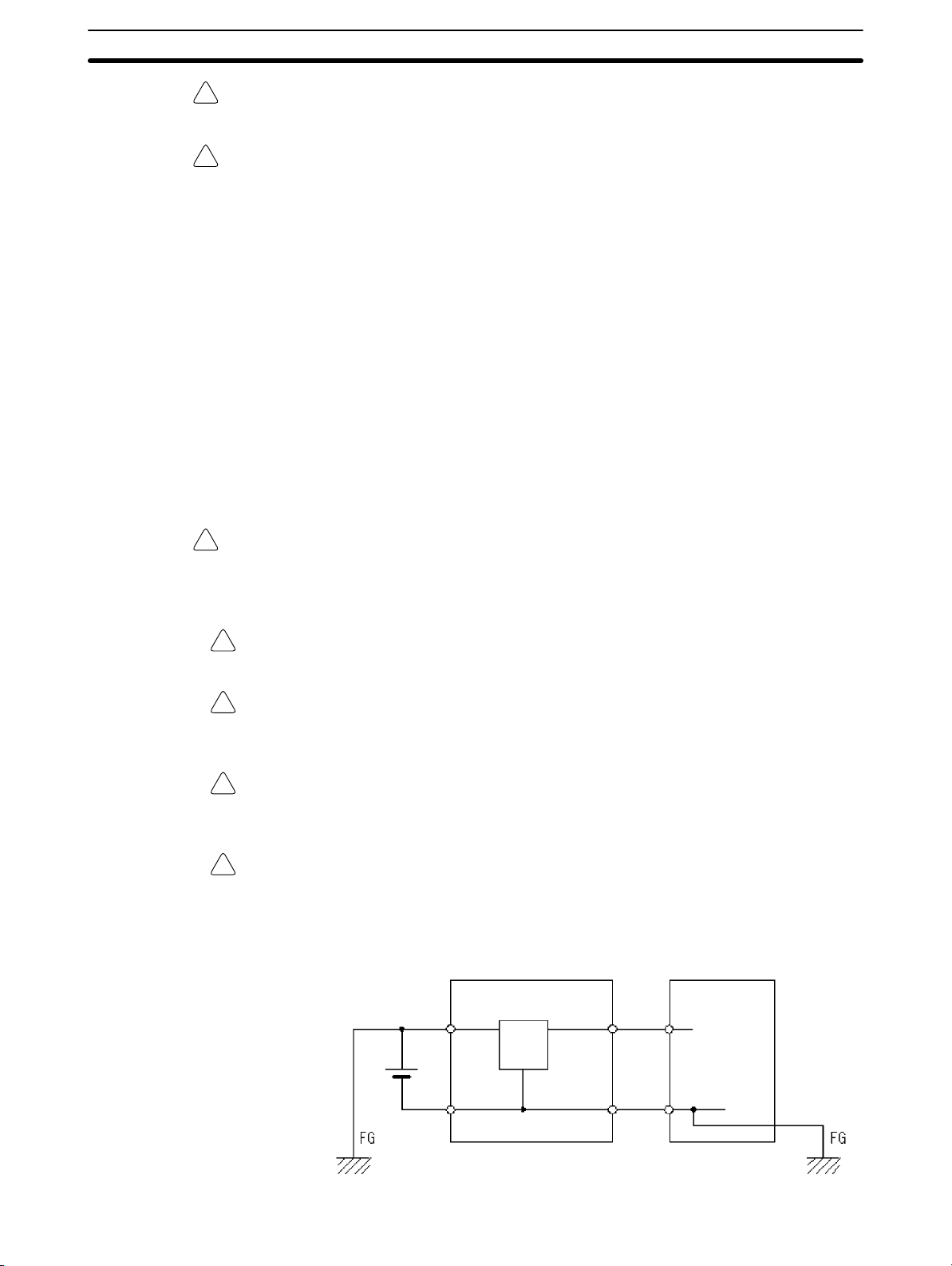
Caution When connecting the PC to a personal computer or other peripheral device,
!
either ground the 0-V side of the PC or do not ground the PC at all. Although
some grounding methods short the 24-V side, as shown in the following diagram, never do so with the PC.
INCORRECT Grounding: Shorting the 24-V side of the Power Supply
Non-isolated DC
24 V
power supply
0 V 0 V
PC
0 V
Peripheral device
xix
Page 19

4 Operating Environment Precautions
Caution Do not operate the control system in the following places:
!
• Locations subject to direct sunlight.
• Locations subject to temperatures or humidity outside the range specified in
the specifications.
• Locations subject to condensation as the result of severe changes in tempera-
ture.
• Locations subject to corrosive or flammable gases.
• Locations subject to dust (especially iron dust) or salts.
• Locations subject to exposure to water, oil, or chemicals.
• Locations subject to shock or vibration.
Caution Take appropriate and sufficient countermeasures when installing systems in the
!
following locations:
• Locations subject to static electricity or other forms of noise.
• Locations subject to strong electromagnetic fields.
• Locations subject to possible exposure to radioactivity.
• Locations close to power supplies.
4Operating Environment Precautions
Caution The operating environment of the PC System can have a large effect on the lon-
!
gevity and reliability of the system. Improper operating environments can lead to
malfunction, failure, and other unforeseeable problems with the PC System. Be
sure that the operating environment is within the specified conditions at installation and remains within the specified conditions during the life of the system.
xx
Page 20

5 Application Precautions
Observe the following precautions when using the PC System.
Caution Failure to abide by the following precautions could lead to faulty operation of the
!
PC or the system, or could damage the PC or PC Units. Always heed these precautions.
Designing Circuits or Creating Ladder Programs
• Fail-safe measures must be taken by the customer to ensure safety in the
event of incorrect, missing, or abnormal signals caused by broken signal lines,
momentary power interruptions, or other causes.
• Construct a control circuit so that power supply for the I/O circuits does not
come ON before power supply for the Unit. If power supply for the I/O circuits
comes ON before power supply for the Unit, normal operation may be temporarily interrupted.
• If the operating mode is changed from RUN or MONITOR mode to PROGRAM
mode, with the IOM Hold Bit ON, the output will hold the most recent status. In
such a case, ensure that the external load does not exceed specifications. (If
operation is stopped because of an operating error, including errors generated
by FALS instructions, the values in the internal memory of the CPU Unit will be
saved, but the outputs will all turn OFF.)
• For models with only the super-capacitor installed, the contents of the READ/
WRITE enable area of the DM area, HR area, AR area, and CNT data area
may be damaged if the power is turned OFF for a long time. To prevent such
damage, provide ladder program that will check AR 1314 to ensure proper operation of the system.
• The life of relays largely varies depending on switching conditions. Be sure to
test operating conditions using actual Units and use the product within the specified number of switchings so as not to cause any performance problems. Using the product with performance problems may result in defective insulation
between circuits or burning of the relays.
5Application Precautions
Installation
Wiring and Connection
• Install the Units properly as specified in the relevant operation manual(s). Im-
proper installation of the Units may result in malfunction.
• Do not install the PC or PC Units in places where the Units may be affected by
excessive noise. Doing so may result in malfunction.
• Install the Units properly so that they will not fall off.
• Be sure that all the mounting screws, terminal screws, and cable connector
screws are tightened to the torque specified in the relevant manuals. Incorrect
tightening torque may result in malfunction.
• Install the Expansion I/O Unit connector cover to the last Expansion I/O Unit to
prevent dust or foreign matter from entering inside the Unit. Not doing so may
result in malfunction.
• Be sure that the terminal blocks, expansion cables, and other items with lock-
ing devices are properly locked into place. Improper locking may result in malfunction.
• Be sure to use cables as specified in the relevant manual(s).
• Install external breakers and take other safety measures against short-circuit-
ing in external wiring. Insufficient safety measures against short-circuiting may
result in burning.
• When wiring signal lines, do not place them in the same duct as high-voltage
lines or power lines. Doing so may result in malfunction.
xxi
Page 21

• Be sure that terminal blocks and connectors are connected in the specified
direction with the correct polarity. Not doing so may result in malfunction.
• Leave the labels attached CPM1 or CPM2A Units when wiring to prevent wir-
ing cuttings from entering the Units.
• Attach the labels supplied with CPM1A or CPM2C Units or provide other pro-
tective covers when wiring to prevent dust or wiring cuttings from entering the
Units.
• Remove the labels after the completion of wiring to ensure proper heat dissipa-
tion. Leaving the labels attached may result in malfunction.
• Use the connectors and wiring materials specified in the relevant manual(s).
• Be sure to wire according to the relevant manual(s). Incorrect wiring may result
in burning.
I/O Connection and System Startup
• Disconnect the functional ground terminal when performing withstand voltage
tests.
• Always use the power supply voltages specified in the operation manual(s). An
incorrect voltage may result in malfunction or burning.
• Take appropriate measures to ensure that the specified power with the rated
voltage and frequency is supplied. Be particularly careful in places where the
power supply is unstable.
• Do not apply voltages to the input terminals in excess of the rated input voltage.
Excess voltages may result in burning.
• Do not apply voltages or connect loads to the output terminals in excess of the
maximum switching capacity. Excess voltage or loads may result in burning.
• Double-check all wiring and switch settings before turning ON the power sup-
ply. Incorrect wiring may result in burning.
• Check the user program for proper execution before actually running it on the
Unit. Not checking the program may result in an unexpected operation.
5Application Precautions
Handling Precautions
• When using, storing, or transporting the product, keep within the specifications
listed in the relevant manual(s).
• Confirm that no adverse effect will occur in the system before attempting any of
the following. Not doing so may result in an unexpected operation.
• Changing the operating mode of the PC.
• Force-setting/force-resetting any bit in memory.
• Changing the present value of any word or any set value in memory.
• Before touching a Unit, be sure to first touch a grounded metallic object to dis-
charge any static built-up. Not doing so may result in malfunction or damage.
• Do not touch the Expansion I/O Unit Connecting Cable while the power is be-
ing supplied to prevent any malfunction due to static electricity.
• Do not pull on the cables or bend the cables beyond their natural limit. Doing
either of these may break the cables.
• Do not place objects on top of the cables. Doing so may break the cables.
• When disposing of Units or other products, be sure to do so according to local
laws and regulations.
• When using a Temperature Sensor Unit with a thermocouple input
(CPM1A-TS001/002, CPM2C-TS001), observe the following precautions:
• With the CPM1A-TS001/002, do not remove the cold junction compensa-
tor attached at the time of delivery. If the cold junction compensator is
removed the Unit will not be able to measure temperatures correctly.
xxii
Page 22

Maintenance
• When replacing a part, be sure to confirm that the rating of a new part is correct.
• When the CPU Unit is replaced, resume operation only after transferring to the
Transportation and Storage
• When transporting the Units, use special packing boxes. Do not subject the
• Store the Units within the following temperature and humidity ranges:
5Application Precautions
• With the CPM1A-TS001/002, each of the input circuits is calibrated with
the cold junction compensator attached to the Unit. If the Unit is used with
the cold junction compensator from other Units, the Unit will not be able to
measure temperatures correctly.
• With the CPM1A-TS001/002 or the CPM2C-TS001, do not touch the cold
junction compensator. Doing so may result in incorrect temperature measurement.
Not doing so may result in malfunction or burning.
new CPU Unit the contents of the DM and HR Areas required for operation. Not
doing so may result in an unexpected operation.
Units or other products to excessive vibration or shock during transportation
and do not to drop them.
Storage temperature: –25 to 65°C
Storage humidity: 25% to 85% (with no icing or condensation)
xxiii
Page 23

SECTION 1
PC Setup
This section explains the PC Setup in the CPM1, CPM1A, CPM2A, CPM2C (including the CPM2C-S), and SRM1(-V2) PCs.
The PC Setup can be used to control the operating parameters. To change the PC Setup, refer to the Operation Manual of the
PC for Programming Console procedures.
Refer to the SSS Operation Manual: C-series PCs for SSS procedures. Refer to the SYSMAC-CPT Support Software Quick
Start Guide (W332) and User Manual (W333) for SYSMAC-CPT Support Software procedures.
If you are not familiar with OMRON PCs or ladder diagram program, you can read 1-1 PC Setup as an overview of the operating parameters available for the CPM1/CPM1A, CPM2A/CPM2C, and SRM1(-V2). You may then want to read Section 5
Memory Areas, Section 6 Ladder-diagram Programming, and related instructions in Section 7 Instruction Set before completing this section.
1-1 PC Setup 2. . . . . . . . . . . . . . . . . . . . . . . . . . . . . . . . . . . . . . . . . . . . . . . . . . . . . . . . . . . . . . . .
1-1-1 Changing the PC Setup 2. . . . . . . . . . . . . . . . . . . . . . . . . . . . . . . . . . . . . . . . . . . . .
1-1-2 CPM1/CPM1A PC Setup Settings 3. . . . . . . . . . . . . . . . . . . . . . . . . . . . . . . . . . . . .
1-1-3 CPM2A/CPM2C PC Setup Settings 7. . . . . . . . . . . . . . . . . . . . . . . . . . . . . . . . . . .
1-1-4 SRM1(-V2) PC Setup Settings 13. . . . . . . . . . . . . . . . . . . . . . . . . . . . . . . . . . . . . . .
1-2 Basic PC Operation and I/O Processes 16. . . . . . . . . . . . . . . . . . . . . . . . . . . . . . . . . . . . . . . .
1-2-1 Startup Mode 16. . . . . . . . . . . . . . . . . . . . . . . . . . . . . . . . . . . . . . . . . . . . . . . . . . . . .
1-2-2 Hold Bit Status 17. . . . . . . . . . . . . . . . . . . . . . . . . . . . . . . . . . . . . . . . . . . . . . . . . . . .
1-2-3 Program Memory Write-protection 17. . . . . . . . . . . . . . . . . . . . . . . . . . . . . . . . . . . .
1-2-4 RS-232C Port Servicing Time (CPM2A/CPM2C/SRM1(-V2) Only) 18. . . . . . . . .
1-2-5 Peripheral Port Servicing Time 18. . . . . . . . . . . . . . . . . . . . . . . . . . . . . . . . . . . . . . .
1-2-6 Cycle Monitor Time 18. . . . . . . . . . . . . . . . . . . . . . . . . . . . . . . . . . . . . . . . . . . . . . . .
1-2-7 Minimum Cycle Time 19. . . . . . . . . . . . . . . . . . . . . . . . . . . . . . . . . . . . . . . . . . . . . .
1-2-8 Input Time Constants 19. . . . . . . . . . . . . . . . . . . . . . . . . . . . . . . . . . . . . . . . . . . . . . .
1-2-9 Error Log Settings 21. . . . . . . . . . . . . . . . . . . . . . . . . . . . . . . . . . . . . . . . . . . . . . . . .
1-3 CPM2C Changes in SW2 21. . . . . . . . . . . . . . . . . . . . . . . . . . . . . . . . . . . . . . . . . . . . . . . . . . .
1
Page 24

1-1SectionPC Setup
1-1 PC Setup
The PC Setup comprises various operating parameters that control PC operation. In order to make the maximum use of PC functionality when using interrupt
processing and communications functions, the PC Setup may be customized
according to operating conditions.
At the time of shipping, the defaults are set for general operating conditions, so
that the PC can be used without having to change the settings. You are, however, advised to check the default values before operation.
Default Values The default values for the PC Setup are 0000 for all words (except for the low
battery error enable in DM 6655 bits 12 to 15 for CPM2A CPU Units). The default
values can be reset at any time by turning ON SR 25210 in PROGRAM mode.
Caution When data memory (DM) is cleared from a Programming Device, the PC Setup
!
settings will also be cleared to all zeros.
1-1-1 Changing the PC Setup
PC Setup settings are accessed at various times depending on the setting, as
described below.
• DM 6600 to DM 6614: Accessed only when PC’s power supply is turned
ON.
• DM 6615 to DM 6644: Accessed only when program execution begins.
• DM 6645 to DM 6655: Accessed regularly when the power is ON.
Since changes in the PC Setup become effective only at the times given above,
the PC will have to be restarted to make changes in DM 6600 to DM 6614 effective, and program execution will have to be restarted to make changes in
DM 6615 to DM 6644 effective.
When DM 6602 bits 00 to 03 are set to protect the program memory, DM 6602
cannot be changed using the PC Setup operation of the Support Software. To
change DM 6602, use the I/O Monitor or DM Edit operation.
Making Changes from a
Programming Device
Errors in the PC Setup If an incorrect PC Setup setting is accessed, a non-fatal error (error code 9B) will
The PC Setup can be read, but not overwritten, from the user program. Writing
can be done only by using a Programming Device.
Although the PC Setup is stored in DM 6600 to DM 6655, settings can be made
and changed only from a Programming Device (e.g., SSS, or Programming
Console). DM 6600 to DM 6644 can be set or changed only while in PROGRAM
mode. DM 6645 to DM 6655 can be set or changed while in either PROGRAM
mode or MONITOR mode. The cycle time will be rather long when the PC Setup
is changed in MONITOR mode.
The following settings can be made in PROGRAM mode from the SSS using
menu operations. All other settings must be made using the hexadecimal setting
operation.
• Startup Mode (DM 6600)
• I/O Hold Bit Status and Forced Status Hold Bit Status (DM 6601)
• Cycle Monitor Time (DM 6618)
• Cycle Time (DM 6619)
• RS-232C Port Settings (DM 6645 to DM 6649)
Note The RS-232C Port Settings (DM 6645 to DM 6649) are not used in
CPM1/CPM1A PCs because these PCs aren’t equipped with an RS-232C port.
be generated, the corresponding error flag (AR 1300 to AR 1302) will be turned
ON, and the default setting will be used instead of the incorrect setting.
2
Page 25

1-1-2 CPM1/CPM1A PC Setup Settings
The PC Setup is broadly divided into four categories: 1) Settings related to basic
PC operation and I/O processes, 2) Settings related to the cycle time, 3) Settings
related to interrupts, and 4) Settings related to communications. This section will
explain the settings according to these classifications.
The following table shows the settings for CPM1/CPM1A PCs in order. Refer to
the page number in the last column for more details on that setting.
Word(s) Bit(s) Function Page
Startup Processing (DM 6600 to DM 6614)
The following settings are effective after transfer to the PC only after the PC is restarted.
DM 6600
DM 6601
DM 6602
DM 6603 00 to 15 Not used.
DM 6604
DM 6605 to
DM 6614
Cycle Time Settings (DM 6615 to DM 6619)
The following settings are effective after transfer to the PC the next time operation is started.
DM 6615,
DM 6616
DM 6617
DM 6618
DM 6619 00 to 15 Cycle time
00 to 07 Startup mode (effective when bits 08 to 15 are set to 02).
00: PROGRAM; 01: MONITOR 02: RUN
08 to 15 Startup mode designation
00: According to communications port setting switch and peripheral port connection
(See table at the bottom of this page.)
01: Continue operating mode last used before power was turned OFF.
02: Setting in 00 to 07
00 to 07 Not used.
08 to 11 IOM Hold Bit (SR 25212) Status at Startup
0: Reset; 1: Maintain (See note 3.)
12 to 15 Forced Status Hold Bit (SR 25211) Status at Startup
0: Reset; 1: Maintain (See note 3.)
00 to 03 Program memory write-protection
0: Program memory unprotected
1: Program memory write-protected (except DM 6602 itself)
04 to 07 Programming Console display language
0: English; 1: Japanese
08 to 15 Not used.
00 to 07 00: If data could not be saved with the built-in capacitor (AR 1314 ON), a memory error will not
be generated.
01: If data could not be saved with the built-in capacitor (AR 1314 ON), a memory error will be
generated.
08 to 15 Not used.
00 to 15 Not used.
00 to 15 Not used.
00 to 07 Servicing time for peripheral port (effective when bits 08 to 15 are set to 01)
00 to 99 (BCD): Percentage of cycle time used to service peripheral.
08 to 15 Peripheral port servicing setting enable
00: 5% of the cycle time
01: Use time in 00 to 07.
00 to 07 Cycle monitor time (effective when bits 08 to 15 are set to 01, 02, or 03)
00 to 99 (BCD): Setting (see 08 to 15)
08 to 15 Cycle monitor enable (Setting in 00 to 07 x unit; 99 s max.)
00: 120 ms (setting in bits 00 to 07 disabled)
01: Setting unit: 10 ms
02: Setting unit: 100 ms
03: Setting unit: 1 s
0000: Variable (no minimum)
0001 to 9999 (BCD): Minimum time in ms
16
17
17
18
18
19
1-1SectionPC Setup
3
Page 26

Word(s) PageFunctionBit(s)
Interrupt Processing (DM 6620 to DM 6639)
The following settings are effective after transfer to the PC the next time operation is started.
DM 6620
DM 6621
DM 6622
DM 6623
DM 6624
DM 6625
DM 6626 to
DM 6627
DM 6628
DM 6629 to
DM 6641
High-speed Counter Settings (DM 6640 to DM 6644)
The following settings are effective after transfer to the PC the next time operation is started.
DM 6640 to
DM 6641
DM 6642
DM 6643,
DM 6644
00 to 03 Input constant for IR 00000 to IR 00002
0: 8 ms; 1: 1 ms; 2: 2 ms; 3: 4 ms; 4: 8 ms; 5: 16 ms; 6: 32 ms; 7: 64 ms; 8: 128 ms
04 to 07 Input constant for IR 00003 and IR 00004 (Setting same as bits 00 to 03)
08 to 11 Input constant for IR 00005 and IR 00006 (Setting same as bits 00 to 03)
12 to 15 Input constant for IR 00007 to IR 00011 (Setting same as bits 00 to 03)
00 to 07 Input constant for IR 001
00: 8 ms; 01: 1 ms; 02: 2 ms; 03: 4 ms; 04: 8 ms; 05: 16 ms; 06: 32 ms; 07: 64 ms; 08:
128 ms
08 to 15 Input constant for IR 002 (Setting same as for IR 001.)
00 to 07 Input constant for IR 003 (Setting same as for IR 001.)
08 to 15 Input constant for IR 004 (Setting same as for IR 001.)
00 to 07 Input constant for IR 005 (Setting same as for IR 001.)
08 to 15 Input constant for IR 006 (Setting same as for IR 001.)
00 to 07 Input constant for IR 007 (Setting same as for IR 001.)
08 to 15 Input constant for IR 008 (Setting same as for IR 001.)
00 to 07 Input constant for IR 009 (Setting same as for IR 001.)
08 to 15 Not used.
00 to 15 Not used.
00 to 03 Interrupt enable for IR 00003 (0: Normal input; 1: Interrupt input; 2: Quick-response)
04 to 07 Interrupt enable for IR 00004 (0: Normal input; 1: Interrupt input; 2: Quick-response)
08 to 11 Interrupt enable for IR 00005 (0: Normal input; 1: Interrupt input; 2: Quick-response)
12 to 15 Interrupt enable for IR 00006 (0: Normal input; 1: Interrupt input; 2: Quick-response)
00 to 15 Not used.
00 to 15 Not used.
00 to 03 High-speed counter mode
0: Up/down counter mode; 4: Incrementing counter mode
04 to 07 High-speed counter reset mode
0: Z phase and software reset; 1: Software reset only
08 to 15 High-speed counter enable
00: Don’t use high-speed counter; 01: Use high-speed counter with settings in 00 to 07
00 to 15 Not used.
1-1SectionPC Setup
19
79
86
4
Page 27

Word(s) PageFunctionBit(s)
Peripheral Port Settings
The following settings are effective after transfer to the PC.
DM 6645 to
DM 6649
DM 6650
DM 6651
DM 6652 00 to 15 Transmission delay (Host Link) (See note 4.)
DM 6653
DM 6654 00 to 15 Not used.
Error Log Settings (DM 6655)
The following settings are effective after transfer to the PC.
DM 6655
00 to 15 Not used.
00 to 07 Port settings
00: Standard (1 start bit, 7-bit data, even parity, 2 stop bits, 9,600 bps)
01: Settings in DM 6651
(Other settings will cause a non-fatal error and AR 1302 will turn ON.)
08 to 11 Link area for 1:1 PC Link via peripheral port:
0: LR 00 to LR 15
12 to 15 Communications mode
0: Host Link; 2: 1:1 PC Link Slave; 3: 1:1 PC Link Master; 4: 1:1 NT Link
(Other settings will cause a non-fatal error and AR 1302 will turn ON.)
00 to 07 Baud rate
00: 1.2K, 01: 2.4K, 02: 4.8K, 03: 9.6K, 04: 19.2K, 05 to 07: Cannot be used (see note
2)
(Other settings will cause a non-fatal error and AR 1302 will turn ON.)
08 to 15 Frame format
Start Length Stop Parity
00: 1 bit 7 bits 1 bit Even
01: 1 bit 7 bits 1 bit Odd
02: 1 bit 7 bits 1 bit None
03: 1 bit 7 bits 2 bits Even
04: 1 bit 7 bits 2 bits Odd
05: 1 bit 7 bits 2 bits None
06: 1 bit 8 bits 1 bit Even
07: 1 bit 8 bits 1 bit Odd
08: 1 bit 8 bits 1 bit None
09: 1 bit 8 bits 2 bits Even
10: 1 bit 8 bits 2 bits Odd
11: 1 bit 8 bits 2 bits None
(Other settings will cause a non-fatal error and AR 1302 will turn ON.)
0000 to 9999: In ms.
(Other settings will cause a non-fatal error and AR 1302 will turn ON.)
00 to 07 Node number (Host Link)
00 to 31 (BCD)
(Other settings will cause a non-fatal error and AR 1302 will turn ON.)
08 to 15 Not used.
00 to 03 Style
0: Shift after 7 records have been stored
1: Store only first 7 records (no shifting)
2 to F: Do not store records
04 to 07 Not used.
08 to 11 Cycle time monitor enable
0: Detect long cycles as non-fatal errors
1: Do not detect long cycles
12 to 15 Not used.
1-1SectionPC Setup
226
21
Note 1. When the startup mode is set to continue the operating mode last used be-
fore the power was turned off, that operating mode will be retained by the
built-in capacitor. If the power remains off for longer than the backup time of
the capacitor, the data may be lost. (For details on the holding time, refer to
the CPM1A or CPM1 Operation Manual.)
5
Page 28

1-1SectionPC Setup
2. Do not set to “05” to “07.” If set to this value, the CPM1/CPM1A will not operate properly and the RUN PC Setup Error Flag (AR 1302 ON) will not turn
ON.
3. Retention of IOM Hold Bit (SR 25212) Status
If the “IOM Hold Bit Status at Startup” (DM 6601, bits 08 to 11) is set to “Maintain” with the IOM Hold Bit (SR 25212) turned ON, operation can be started
with the I/O memory (I/O, IR, LR) status just as it was before the power was
turned OFF. (The input area is refreshed at startup, however, so it is overwritten by the most recently updated input status.)
Retention of Forced Status Hold Bit (SR 25211) Status
If the “Forced Status Hold Bit Status at Startup” (DM 6601, bits 12 to 15) is
set to “Maintain” with the Forced Status Hold Bit (SR 25211) turned ON, operation can be started with the forced set/reset status just as it was before
the power was turned OFF. (When starting up in RUN Mode, however, the
forced set/reset status is cleared.)
Even if the “IOM Hold Bit Status at Startup” or “Forced Status Hold Bit Status
at Startup” is set to “Maintain,” the IOM Hold Bit (SR 25212) or Forced Status
Hold Bit (SR 25211) status may be cleared if the power remains OFF for
longer than the backup time of the built-in capacitor. (For details on the holding time, refer to the CPM1A or CPM1 Operation Manual.) At this time the
I/O memory will also be cleared, so set up the system so that clearing the I/O
memory will not cause problems.
4. The transmission delay is the delay between the previous transmission and
the next transmission.
Host computer
Programmable Controller
Command
Command
Response
Transmission delay time
Response
5. If an out-of-range value is set, the following communications conditions will
result. In that case, reset the value so that it is within the permissible range.
Communications mode: Host Link
Communications format: Standard settings
(1 start bit, 7-bit data; even parity, 2 stop bits,
9,600 bps)
Transmission delay: No
Node number: 00
6
Page 29

1-1-3 CPM2A/CPM2C PC Setup Settings
pp
The PC Setup is broadly divided into four categories: 1) Settings related to basic
PC operation and I/O processes, 2) Settings related to pulse output functions, 3)
Settings related to interrupts, and 4) Settings related to communications. This
section will explain the settings according to these classifications.
The following table shows the setting in order in the DM area. For details, refer to
the page numbers shown.
Word(s) Bit(s) Function Page
Startup Processing (DM 6600 to DM 6614)
The following settings are effective after transfer to the PC only after the PC is restarted.
DM 6600
DM 6601
DM 6602
DM 6603 00 to 15 Not used.
DM 6604
DM 6605 to
DM 6614
00 to 07 Startup mode (effective when bits 08 to 15 are set to 02).
00: PROGRAM; 01: MONITOR; 02: RUN
08 to 15 Startup mode designation
00: Mode set on Programming Console switch if Programming Console is connected.
No Programming Device connected: RUN Mode
Programming Console connected: Mode set on mode switch on Programming
Console
Other Programming Device connected: PROGRAM Mode
01: Continue operating mode last used before power was turned OFF.
02: Setting in 00 to 07
The setting of the switch SW2 will affect the operating mode for all CPM2C CPU Units
produced before 1 September 2000. Refer to 1-3 Changes in SW2 for details.
00 to 07 Not used.
08 to 11 IOM Hold Bit (SR 25212) Status at Startup
0: Reset to 0; 1: Maintain previous status
12 to 15 Forced Status Hold Bit (SR 25211) Status at Startup
0: Reset to 0; 1: Maintain previous status
00 to 03 Program memory write-protection
0: Program memory unprotected
1: Program memory write-protected (except DM 6602 itself)
04 to 07 Programming Console display language
0: English; 1: Japanese
08 to 11 Expansion instruction function code assignments
0: Default settings
1: User assignments
12 to 15 Not used.
00 to 07 00: A memory error will not be generated if data could not be retained by the battery.
01: A memory error will be generated if data could not be retained by the battery.
08 to 15 Not used.
00 to 15 Not used.
16
17
17
161
1-1SectionPC Setup
Note For CPM2C PCs with lot number of 3180O or earlier, the startup operating mode
will be as shown in the following table if bits 08 to 15 of DM 6600 are set to 00.
Peripheral port
connected to
Nothing PROGRAM RUN
Programming
Console
Other Programming
Device
Mode set on Programming
Console mode switch
PROGRAM (The CPM2C will
not be able to communicate
with Programming Device.)
Communications port setting switch
SW2 OFF SW2 ON
PROGRAM (The CPM2C will
not be able to communicate
with Programming Console.)
PROGRAM
7
Page 30

Word(s) Bit(s) Function Page
Cycle Time Settings (DM 6615 to DM 6619)
The following settings are effective after transfer to the PC the next time operation is started.
DM 6615 00 to 15 Not used.
DM 6616
DM 6617
DM 6618
00 to 07 Servicing time for RS-232C port (Effective when bits 08 to 15 are set to 01.)
00 to 99 (BCD): Percentage of cycle time used to service RS-232C port.
08 to 15 RS-232C port servicing setting enable
00: 5% of the cycle time
01: Use time in bits 00 to 07.
00 to 07 Servicing time for peripheral port (Effective when bits 08 to 15 are set to 01.)
00 to 99 (BCD): Percentage of cycle time used to service peripheral.
08 to 15 Peripheral port servicing setting enable
00: 5% of the cycle time
01: Use time in bits 00 to 07.
00 to 07 Cycle monitor time (Effective when bits 08 to 15 are set to 01, 02, or 03.)
00 to 99 (BCD): Setting (See bits 08 to 15, below.)
A fatal error will be generated and PC operation will stop if the cycle time exceeds the
cycle monitor time set here.
08 to 15 Cycle monitor enable (Setting in 00 to 07 × units; 99 s max.)
00: 120 ms (setting in bits 00 to 07 disabled)
01: Setting units: 10 ms
02: Setting units: 100 ms
03: Setting units: 1 s
18
18
18
1-1SectionPC Setup
DM 6619 00 to 15 Minimum cycle time
0000: Variable (no minimum)
0001 to 9999 (BCD): Minimum time in ms
Interrupt Processing (DM 6620 to DM 6639)
The following settings are effective after transfer to the PC the next time operation is started.
DM 6620
DM 6621
DM 6622
DM 6623
DM 6624
DM 6625
DM 6626 to
DM 6627
DM6628
00 to 03 Input time constant for IR 00000 to IR 00002
0: 10 ms; 1: 1 ms; 2: 2 ms; 3: 3 ms; 4: 5 ms; 5: 10 ms; 6: 20 ms; 7: 40 ms; 8: 80 ms
04 to 07 Input time constant for IR 00003 and IR 00004 (Setting same as bits 00 to 03)
08 to 11 Input time constant for IR 00005 and IR 00006 (Setting same as bits 00 to 03)
12 to 15 Input time constant for IR 00007 to IR 00011 (Setting same as bits 00 to 03)
00 to 07 Input time constant for IR 001
00: 10 ms 01: 1 ms 02: 2 ms 03: 3 ms 04: 5 ms
05: 10 ms 06: 20 ms 07: 40 ms 08: 80 ms
08 to 15 Input constant for IR 002 (Setting same as for IR 001.)
00 to 07 Input constant for IR 003 (Setting same as for IR 001.)
08 to 15 Input constant for IR 004 (Setting same as for IR 001.)
00 to 07 Input constant for IR 005 (Setting same as for IR 001.)
08 to 15 Input constant for IR 006 (Setting same as for IR 001.)
00 to 07 Input constant for IR 007 (Setting same as for IR 001.)
08 to 15 Input constant for IR 008 (Setting same as for IR 001.)
00 to 07 Input constant for IR 009 (Setting same as for IR 001.)
08 to 15 Not used.
00 to 15 Not used.
00 to 03 Interrupt enable for IR 00003 (0: Normal input; 1: Interrupt input; 2: Quick-response)
04 to 07 Interrupt enable for IR 00004 (0: Normal input; 1: Interrupt input; 2: Quick-response)
08 to 11 Interrupt enable for IR 00005 (0: Normal input; 1: Interrupt input; 2: Quick-response)
(Set to 0 in CPM2C CPU Units with 10 I/O points.)
12 to 15 Interrupt enable for IR 00006 (0: Normal input; 1: Interrupt input; 2: Quick-response)
(This input does not exist in CPM2C CPU Units with 10 I/O points.)
19
19
30
8
Page 31

Word(s) PageFunctionBit(s)
DM 6629
DM 6630 to
DM 6641
High-speed Counter Settings (DM 6640 to DM 6644)
The following settings are effective after transfer to the PC the next time operation is started.
DM 6640 to
DM 6641
DM 6642
DM 6643,
DM 6644
RS-232C Port Communications Settings
The following settings are effective after transfer to the PC.
If the CPM2A CPU Unit’s Communications Switch is ON, communications through the CPM2A’s RS-232C port are gov-
erned by the default settings (all 0) regardless of the settings in DM 6645 through DM 6649.
If pin 2 of the CPM2C CPU Unit’s DIP switch is ON, communications through the CPM2C’s RS-232C port are governed
by the default settings (all 0) regardless of the settings in DM 6645 through DM 6649.
DM 6645
00 to 03 PV coordinate system for pulse output 0
0: Relative coordinates; 1: Absolute coordinates
04 to 07 PV coordinate system for pulse output 1
0: Relative coordinates; 1: Absolute coordinates
08 to 15 Not used.
00 to 15 Not used.
00 to 15 Not used.
00 to 03 High-speed counter mode
0: Differential phase mode (5 kHz)
1: Pulse + direction input mode (20 kHz)
2: Up/down input mode (20 kHz)
4: Increment mode (20 kHz)
04 to 07 High-speed counter reset mode
0: Z phase and software reset; 1: Software reset only
08 to 15 High-speed counter/Synchronized pulse control for IR 00000 to IR 00002
00: Don’t use either function.
01: Use as high-speed counters.
02: Use for synchronized pulse control (10 to 500 Hz).
03: Use for synchronized pulse control (20 Hz to 1 kHz).
04: Use for synchronized pulse control (300 Hz to 20 kHz).
00 to 15 Not used.
00 to 03 Port settings
0: Standard (1 start bit, 7 data bits, even parity, 2 stop bits, 9,600 bps), Host Link unit
number: 0
1: Settings in DM 6646
(Any other setting will cause a non-fatal error and AR 1302 will turn ON.)
04 to 07 CTS control setting
0: Disable CTS control; 1: Enable CTS control
(Any other setting will cause a non-fatal error and AR 1302 will turn ON.)
08 to 11 Link words for 1:1 data link
0: LR 00 to LR 15 (Any other settings are ineffective.)
12 to 15 Communications mode
0: Host Link; 1: No-protocol; 2: 1:1 PC Link Slave; 3: 1:1 PC Link Master; 4: NT Link
(Any other setting causes a non-fatal error and turns ON AR 1302.)
101
47, 56
226
1-1SectionPC Setup
9
Page 32

Word(s) PageFunctionBit(s)
DM 6646
DM 6647 00 to 15 Transmission delay (0000 to 9999 BCD sets a delay of 0 to 99,990 ms.)
DM 6648
DM 6649
00 to 07 Baud rate
00: 1,200 bps; 01: 2,400 bps; 02: 4,800 bps; 03: 9,600 bps; 04: 19,200 bps
08 to 15 Frame format
Start bits Data bits Stop bits Parity
00: 1 bit 7 bits 1 bit Even
01: 1 bit 7 bits 1 bit Odd
02: 1 bit 7 bits 1 bit None
03: 1 bit 7 bits 2 bits Even
04: 1 bit 7 bits 2 bits Odd
05: 1 bit 7 bits 2 bits None
06: 1 bit 8 bits 1 bit Even
07: 1 bit 8 bits 1 bit Odd
08: 1 bit 8 bits 1 bit None
09: 1 bit 8 bits 2 bits Even
10: 1 bit 8 bits 2 bits Odd
11: 1 bit 8 bits 2 bits None
(Any other setting specifies standard settings (1 start bit, 7 data bits; even parity, 2 stop
bits, 9,600 bps), causes a non-fatal error, and turns ON AR 1302.)
(Any other setting specifies a delay of 0 ms, causes a non-fatal error, and turns ON
AR 1302.)
00 to 07 Node number (Host Link)
00 to 31 (BCD)
(Any other setting specifies a node number of 00, causes a non-fatal error, and turns
ON AR 1302.)
08 to 11 Start code selection for no-protocol communications
0: Disables start code; 1: Enables start code in DM 6649
(Any other setting disables the start code, causes a non-fatal error, and turns ON
AR 1302.)
12 to 15 End code selection for no-protocol communications
0: Disables end code; 1: Enables end code in DM 6649; 2: Sets end code of CR, LF.
(Any other setting disables the end code, causes a non-fatal error, and turns ON
AR 1302.)
00 to 07 Start code (00 to FF)
(This setting is valid only when bits 8 to 11 of DM 6648 are set to 1.)
08 to 15 When bits 12 to 15 of DM 6648 set to 0:
Sets the number of bytes to receive. (00: 256 bytes; 01 to FF: 1 to 255 bytes)
When bits 12 to 15 of DM 6648 set to 1:
Sets the end code. (00 to FF)
1-1SectionPC Setup
226
226
226
226
10
Page 33

1-1SectionPC Setup
Word(s) PageFunctionBit(s)
Peripheral Port Communications Settings
The following settings are effective after transfer to the PC.
If the CPM2A CPU Unit’s Communications Switch is ON, communications through the peripheral port are governed by
the default settings (all 0) regardless of the settings in DM 6650 through DM 6654.
The CPM2A’s Communications Switch setting has no effect on communications with a Programming Console connected
to the peripheral port or Support Software set for peripheral bus communications. The CPM2A CPU Unit will auto-detect
either Programming Device and automatically establish communications.
SW2 on the CPM2C CPU Unit must be OFF in order for communications through the CPM2C’s peripheral port to be governed by the settings in DM 6650 through DM 6654.
DM 6650
DM 6651
DM 6652 00 to 15 Transmission delay (0000 to 9999 BCD sets a delay of 0 to 99,990 ms.)
DM 6653
00 to 03 Port settings
00: Standard (1 start bit, 7 data bits, even parity, 2 stop bits, 9,600 bps), Host Link unit
number: 0
01: Settings in DM 6651
(Any other setting specifies standard settings, causes a non-fatal error, and turns ON
AR 1302.)
04 to 11 Not used.
12 to 15 Communications mode
0: Host Link or peripheral bus; 1: No-protocol
(Any other setting specifies Host Link, causes a non-fatal error, and turns ON
AR 1302.)
00 to 07 Baud rate
00: 1,200 bps; 01: 2,400 bps; 02: 4,800 bps; 03: 9,600 bps; 04: 19,200 bps
08 to 15 Frame format
Start bits Data bits Stop bits Parity
00: 1 bit 7 bits 1 bit Even
01: 1 bit 7 bits 1 bit Odd
02: 1 bit 7 bits 1 bit None
03: 1 bit 7 bits 2 bits Even
04: 1 bit 7 bits 2 bits Odd
05: 1 bit 7 bits 2 bits None
06: 1 bit 8 bits 1 bit Even
07: 1 bit 8 bits 1 bit Odd
08: 1 bit 8 bits 1 bit None
09: 1 bit 8 bits 2 bits Even
10: 1 bit 8 bits 2 bits Odd
11: 1 bit 8 bits 2 bits None
(Any other setting specifies standard settings (1 start bit, 7 data bits; even parity, 2 stop
bits, 9,600 bps), causes a non-fatal error, and turns ON AR 1302.)
(Any other setting specifies a delay of 0 ms, causes a non-fatal error, and turns ON
AR 1302.)
00 to 07 Node number (Host Link)
00 to 31 (BCD)
(Any other setting specifies a node number of 00, causes a non-fatal error, and turns
ON AR 1302.)
08 to 11 Start code selection for no-protocol communications
0: Disables start code; 1: Enables start code in DM 6649
(Any other setting disables the start code, causes a non-fatal error, and turns ON
AR 1302.)
12 to 15 End code selection for no-protocol communications
0: Disables end code; 1: Enables end code in DM 6649; 2: Sets end code of CR, LF.
(Any other setting disables the end code, causes a non-fatal error, and turns ON
AR 1302.)
226
226
11
Page 34

Word(s) PageFunctionBit(s)
DM 6654
Error Log Settings (DM 6655)
The following settings are effective after transfer to the PC.
DM 6655
00 to 07 Start code (00 to FF)
(This setting is valid only when bits 8 to 11 of DM 6648 are set to 1.)
08 to 15 When bits 12 to 15 of DM 6648 set to 0:
Sets the number of bytes to receive. (00: 256 bytes; 01 to FF: 1 to 255 bytes)
When bits 12 to 15 of DM 6648 set to 1:
Sets the end code. (00 to FF)
00 to 03 Style
0: Shift after 7 records have been stored
1: Store only first 7 records (no shifting)
2 to F: Do not store records
04 to 07 Not used.
08 to 11 Cycle time monitor enable
0: Generate a non-fatal error for a cycle time that is too long.
1: Do not generate a non-fatal error.
12 to 15 Low battery error enable
0: Generate a non-fatal error for low battery voltage.
1: Do not generate a non-fatal error.
Low battery error detection is disabled (i.e., set to 1) by default in CPU Units that do
not have a clock. If the PC Setup is cleared, the setting will changed to 0 and a low
battery error will occur.
Bits 12 to 15 should always be set to 0 when the optional CPM2C-BAT01 is mounted.
1-1SectionPC Setup
226
21
12
Page 35

1-1-4 SRM1(-V2) PC Setup Settings
The PC Setup is broadly divided into three categories: 1) Settings related to basic PC operation and I/O processes, 2) Settings related to the cycle time, and 3)
Settings related to communications. This section will explain the settings according to these classifications.
The following table shows the settings for SRM1(-V2) PCs in order. Refer to the
page number in the last column for more details on that setting.
Word(s) Bit(s) Function Page
Startup Processing (DM 6600 to DM 6614)
The following settings are effective after transfer to the PC only after the PC is restarted.
DM 6600
DM 6601
DM 6602
DM 6603
DM 6604
DM 6605 to
DM 6614
Cycle Time Settings (DM 6615 to DM 6619)
The following settings are effective after transfer to the PC the next time operation is started.
DM 6615 00 to 15 Not used.
DM 6616
DM 6617
00 to 07 Startup mode (effective when bits 08 to 15 are set to 02).
00: PROGRAM; 01: MONITOR 02: RUN
08 to 15 Startup mode designation
00: Programming Console switch
01: Continue operating mode last used before power was turned off
02: Setting in 00 to 07
00 to 07 Not used.
08 to 11 IOM Hold Bit (SR 25212) Status
0: Reset; 1: Maintain (See caution on page 17.)
12 to 15 Forced Status Hold Bit (SR 25211) Status
0: Reset; 1: Maintain
00 to 03 Program memory write-protection
0: Program memory unprotected
1: Program memory write-protected (except DM 6602 itself)
04 to 07 Programming Console display language
0: English; 1: Japanese
08 to 11 Expansion Instructions
0: Default settings; 1: User settings
12 to 15 Not used.
00 to 03 Maximum number of CompoBus/S devices
0: Max. no. 32
1: Max. no. 16
04 to 07 CompoBus/S communications mode setting (V2 only)
0: High-speed communications
1: Long-distance communications
08 to 15 Not used.
00 to 07 00: If data could not be saved for a power interruption (AR 1314 ON), a memory error will not be
generated.
01: If data could not be saved for a power interruption (AR 1314 ON), a memory error will be
generated.
08 to 15 Not used.
00 to 15 Not used.
00 to 07 Servicing time for RS-232C port (effective when bits 08 to 15 are set)
00 to 99 (BCD): Percentage for cycle time used to service peripheral.
08 to 15 RS-232C port servicing enable
00: 5% of the cycle time
01: Use time in 00 to 07.
00 to 07 Servicing time for peripheral port (effective when bits 08 to 15 are set to 01)
00 to 99 (BCD): Percentage of cycle time used to service peripheral.
08 to 15 Peripheral port servicing setting enable
00: 5% of the cycle time
01: Use time in 00 to 07.
16
17
17
18
18
1-1SectionPC Setup
13
Page 36

Word(s) PageFunctionBit(s)
DM 6618
DM 6619 00 to 15 Cycle time
DM 6620 to
DM 6644
RS-232C Port Settings
The following settings are effective after transfer to the PC.
DM 6645
DM 6646
DM 6647 00 to 15 Transmission delay (Host Link)
DM 6648
00 to 07 Cycle monitor time (effective when bits 08 to 15 are set to 01, 02, or 03)
00 to 99 (BCD): Setting (see 08 to 15)
08 to 15 Cycle monitor enable (Setting in 00 to 07 x unit; 99 s max.)
00: 120 ms (setting in bits 00 to 07 disabled)
01: Setting unit: 10 ms
02: Setting unit: 100 ms
03: Setting unit: 1 s
0000: Variable (no minimum)
0001 to 9999 (BCD): Minimum time in ms
00 to 15 Not used.
00 to 03 Port settings
0: Standard (1 start bit, 7-bit data, even parity, 2 stop bits, 9,600 bps)
1: Settings in DM 6646
04 to 07 CTS control settings
0: Disable; 1: Set
08 to 11 When using a 1:1 data link: Sets the link area for 1:1 PC Link.
0: LR 00 to LR 15
Not 0: Disable
When using a 1:N NT Link: Sets the maximum PT node number.
1 to 7
12 to 15 Communications mode
0: Host Link; 1: No-protocol; 2: 1:1 PC Link Slave; 3: 1:1 PC Link Master; 4: 1:1 NT
Link; 5: 1:N NT Link
(Any other setting specifies Host Link mode, causes a non-fatal error, and turns ON
AR 1302.)
The 1:N NT Link is supported by SRM1-C02-V2 only.
00 to 07 Baud rate
00: 1.2K, 01: 2.4K, 02: 4.8K, 03: 9.6K, 04: 19.2K
08 to 15 Frame format
Start Length Stop Parity
00: 1 bit 7 bits 1 bit Even
01: 1 bit 7 bits 1 bit Odd
02: 1 bit 7 bits 1 bit None
03: 1 bit 7 bits 2 bits Even
04: 1 bit 7 bits 2 bits Odd
05: 1 bit 7 bits 2 bits None
06: 1 bit 8 bits 1 bit Even
07: 1 bit 8 bits 1 bit Odd
08: 1 bit 8 bits 1 bit None
09: 1 bit 8 bits 2 bits Even
10: 1 bit 8 bits 2 bits Odd
11: 1 bit 8 bits 2 bits None
Other: 1 bit 7 bits 2 bits Even
AR 1302 will turn ON to indicate a non-fatal system setting error if any value not between 00 and 11 is set.
0000 to 9999 (BCD): Set in units of 10 ms, e.g., setting of 0001 equals 10 ms
00 to 07 Node number (Host Link, effective when bits 12 to 15 of DM 6645 are set to 0.)
00 to 31 (BCD)
08 to 11 Start code enable (RS-232C, effective when bits 12 to 15 of DM 6645 are set to 1.)
0: Disable; 1: Set
12 to 15 End code enable (RS-232C, effective when bits 12 to 15 of DM 6645 are set to 1.)
0: Disable (number of bytes received)
1: Set (specified end code)
2: CR, LF
1-1SectionPC Setup
18
19
268
14
Page 37

Word(s) PageFunctionBit(s)
DM 6649
Peripheral Port Settings
The following settings are effective after transfer to the PC.
DM 6650
DM 6651
00 to 07 Start code (RS-232C)
00 to FF (binary)
08 to 15 When bits 12 to 15 of DM 6648 are set to 0:
Number of bytes received
00: Default setting (256 bytes)
01 to FF: 1 to 255 bytes
When bits 12 to 15 of DM 6648 are set to 1:
End code (RS-232C)
00 to FF (binary)
00 to 03 Port settings
00: Standard (1 start bit, 7-bit data, even parity, 2 stop bits, 9,600 bps)
01: Settings in DM 6651
(Other settings will cause a non-fatal error and AR 1302 will turn ON.)
04 to 07 Not used.
08 to 11 Not used.
12 to 15 Communications mode
0: Host Link; 1: No-protocol
(Other settings will cause a non-fatal error and AR 1302 will turn ON.)
00 to 07 Baud rate
00: 1.2K, 01: 2.4K, 02: 4.8K, 03: 9.6K, 04: 19.2K
08 to 15 Frame format
Start Length Stop Parity
00: 1 bit 7 bits 1 bit Even
01: 1 bit 7 bits 1 bit Odd
02: 1 bit 7 bits 1 bit None
03: 1 bit 7 bits 2 bits Even
04: 1 bit 7 bits 2 bits Odd
05: 1 bit 7 bits 2 bits None
06: 1 bit 8 bits 1 bit Even
07: 1 bit 8 bits 1 bit Odd
08: 1 bit 8 bits 1 bit None
09: 1 bit 8 bits 2 bits Even
10: 1 bit 8 bits 2 bits Odd
11: 1 bit 8 bits 2 bits None
Other: 1 bit 7 bits 2 bits Even
AR 1302 will turn ON to indicate a non-fatal system setting error if any value not between 00 and 11 is set.
1-1SectionPC Setup
268
268
DM 6652 00 to 15 Transmission delay (Host Link)
0000 to 9999 (BCD): Set in units of 10 ms.
(Other settings will cause a non-fatal error and AR 1302 will turn ON.)
DM 6653
00 to 07 Node number (Host Link)
00 to 31 (BCD)
(Other settings will cause a non-fatal error and AR 1302 will turn ON.)
08 to 11 Start code enable (RS-232C, effective when bits 12 to 15 of DM6650 are set to 1.)
0: Disable
1: Set
12 to 15 End code enable (RS-232C, effective when bits 12 to 15 of DM6650 are set to 1.)
0: Disable (number of bytes received)
1: Set (specified end code)
2: CR, LF
268
15
Page 38

Word(s) PageFunctionBit(s)
DM 6654
Error Log Settings (DM 6655)
The following settings are effective after transfer to the PC.
DM 6655
00 to 07 Start code (effective when bits 08 to 11 of DM6650 are set to 1.)
00: 256 bytes
01 to FF: 1 to 255 bytes
08 to 15 End code
When bits 12 to 15 of DM6653 are set to 0:
00: 256 bytes
01 to FF: 1 to 255 bytes
When bits 12 to 15 of DM6653 are set to 1:
Setting: 00 to FF (binary)
00 to 03 Style
0: Shift after 7 records have been stored
1: Store only first 7 records
Errors will not be stored if other values are set.
04 to 07 Not used.
08 to 11 Cycle time monitor enable
0: Detect long cycles as non-fatal errors
1: Do not detect long cycles
12 to 15 Low battery error enable
0: Generate a non-fatal error for low battery voltage.
1: Do not generate a non-fatal error.
1-2SectionBasic PC Operation and I/O Processes
268
21
Note If an out-of-range value is set, the following communications conditions will re-
sult. In that case, reset the value so that it is within the permissible range.
Communications mode: Host Link
Communications format: Standard settings
(1 start bit, 7-bit data; even parity, 2 stop bits,
9,600 bps)
Transmission delay: No
Node number: 00
1-2 Basic PC Operation and I/O Processes
This section explains the PC Setup settings related to basic operation and I/O
processes.
1-2-1 Startup Mode
The operation mode the PC will start in when power is turned on can be set as
shown below.
Startup Mode Designation
00: Programming Console Mode Selector (If not connected: RUN mode)
01: Operating mode last used before power was turned off
02: Mode set in bits 00 to 07
Startup Mode (Bits 08 to 15: Valid when bits 00 to 07 are set to 02)
00: PROGRAM mode
01: MONITOR mode
02: RUN mode
Bit
DM6600
15
0
16
Default: Programming Console Mode Selector or RUN mode when Programming
Console is not connected.
Page 39

Note When the “startup mode designation” is set to 00 and pin 2 of the CPM2C CPU
1-2-2 Hold Bit Status
1-2SectionBasic PC Operation and I/O Processes
Unit’s DIP switch is ON, the CPM2C will enter RUN mode automatically, regardless of the Programming Console’s mode switch setting.
Make the settings shown below to determine whether, when the power supply is
turned on, the Forced Status Hold Bit (SR 25211) and/or IOM Hold Bit
(SR 25212) will retain the status that was in effect when the power was last
turned off, or whether the previous status will be cleared.
Bit
15 0
DM6601
00
SR 25211 setting
0: Clear status
1: Retain status
SR 25212 setting
0: Clear status
1: Retain status
Default: Clear both.
Always 00
The Forced Status Hold Bit (SR 25211) determines whether or not the forced
set/reset status is retained when changing from PROGRAM mode to MONITOR
mode.
The IOM Hold Bit (SR 25212) determines whether or not the status of IR bits and
LR bits is retained when PC operation is started and stopped.
Caution In PCs with capacitor backup, do not use the I/O Hold Bit Status and Forced Sta-
!
tus Hold Bit Status Bits (DM 6601) when the power to the PC is going to be
turned off longer than the memory backup time of the internal capacitor. If the
memory backup time is exceeded, memory status will be unstable even if the I/O
Hold Bit Status and Forced Status Hold Bit Status Bits are used. Unpredictable
results may occur if operation is attempted with unstable memory status.
Note 1. The memory backup time of the internal capacitor varies with the ambient
temperature, but is 20 days at 25C. Refer to hardware specifications for
more details.
2. The memory backup time assumes that the internal capacitor is fully
charged before power is turned off. Fulling charging the capacitor requires
that power is supplied to the CPU Unit for at least 15 minutes.
1-2-3 Program Memory Write-protection
In CPM1, CPM1A, CPM2A, and CPM2C PCs, the program memory can be protected by setting bits 00 to 03 of DM 6602 to 1. Bits 04 to 07 determine whether
Programming Console messages are displayed in English or Japanese.
Programming Console messages
0: English
1: Japanese
Program memory
0: Not write-protected
1: Write-protected
Default: English displays, not write-protected
Bit
DM6602
15 0
00
Always 00
17
Page 40

Note DM 6602 itself can still be changed after the program memory has been write-
protected by setting bits 04 to 07 of DM 6602 to 1.
1-2-4 RS-232C Port Servicing Time (CPM2A/CPM2C/SRM1(-V2) Only)
The following settings are used to determine the percentage of the cycle time
devoted to servicing the RS-232C port.
Bit
15 0
DM6616
Servicing time setting enable
00: Disabled (5% used)
01: Enabled (setting in bits 00 to 07 used)
Servicing time (%, valid with bits 08 to 15 are 01)
00 to 99 (BCD, two digits)
Default: 5% of cycle time
Example: If DM 6616 is set to 0110, the RS-232C port will be serviced for 10% of
the cycle time.
The servicing time will be 0.34 ms minimum.
The entire servicing time will not be used unless processing requests exist.
1-2SectionBasic PC Operation and I/O Processes
1-2-5 Peripheral Port Servicing Time
The following settings are used to determine the percentage of the cycle time
devoted to servicing the peripheral port.
Servicing time setting enable
00: Disabled (5% used)
01: Enabled (setting in bits 00 to 07 used)
Servicing time (%, valid with bits 08 to 15 are 01)
00 to 99 (BCD, two digits)
Default: 5% of cycle time
Example: If DM 6617 is set to 0115, the peripheral port will be serviced for 15%
of the cycle time.
The servicing time will be 0.34 ms minimum.
The entire servicing time will not be used unless processing requests exist.
1-2-6 Cycle Monitor Time
Bit
DM6617
Bit
DM6618
15 0
15 0
18
Cycle Monitor Time Enable and Units
00: Setting disabled (time fixed at 120 ms)
01: Setting in 00 to 07 enabled; units:10 ms
02: Setting in 00 to 07 enabled; units:100 ms
03: Setting in 00 to 07 enabled; units:1 s
Cycle monitor time setting (When bits 08 to 15 are not 00)
00 to 99 (2 digits BCD; units set in bits 08 to 15.)
Default: 120 ms.
Page 41

1-2SectionBasic PC Operation and I/O Processes
The cycle monitor time is used for checking for extremely long cycle times, as
can happen when the program goes into an infinite loop. If the cycle time exceeds the cycle monitor setting, a fatal error (FALS 9F) will be generated.
Note 1. The units used for the maximum and current cycle times recorded in the AR
area (AR 14 and AR 15) are determined by the setting for the cycle monitor
time in DM 6618, as shown below.
Bits 08 to 15 set to 01: 0.1 ms
Bits 08 to 15 set to 02: 1 ms
Bits 08 to 15 set to 03: 10 ms
2. If the cycle time is 1 s or longer, the cycle time read from Programming Devices will be 999.9 ms. The correct maximum and current cycle times will be
recorded in the AR area.
Example
If 0230 is set in DM 6618, an FALS 9F error will not occur until the cycle time
exceeds 3 s. If the actual cycle time is 2.59 s, the current cycle time stored in the
AR area will be 2590 (ms), but the cycle time read from a Programming Device
will be 999.9 ms.
A “cycle time over” error (non-fatal) will be generated when the cycle time exceeds 100 ms unless detection of long cycle times is disable using the setting in
DM 6655.
1-2-7 Minimum Cycle Time
Make the settings shown below to standardize the cycle time and to eliminate
variations in I/O response time by setting a minimum cycle time.
If the actual cycle time is shorter than the minimum cycle time, execution will wait
until the minimum time has expired. If the actual cycle time is longer than the
minimum cycle time, then operation will proceed according to the actual cycle
time. AR 2405 will turn ON if the minimum cycle time is exceeded.
1-2-8 Input Time Constants
Make the settings shown below to set the time from when the actual inputs from
the DC Input Unit are turned ON or OFF until the corresponding input bits are
updated (i.e., until their ON/OFF status is changed). Make these settings when
you want to adjust the time until inputs stabilize.
Increasing the input time constant can reduce the effects from chattering and
external noise.
Bit
15 0
DM6619
Cycle time (4 digits BCD)
0000:Cycle time variable
0001 to 9999: Minimum cycle time (Unit: 1 ms)
Default: Cycle time variable
Input from an input device
such as a limit switch
Input bit status
The SRM1(-V2) does not have this setting.
t
t
Input time constant
19
Page 42

1-2SectionBasic PC Operation and I/O Processes
CPM1/CPM1A PCs Set the input time constants for CPM1/CPM1A inputs from a Programming De-
vice.
Input Time Constants for IR 000
Bit
15 0
DM 6620
Time constant for IR 00007 to IR 00011 (1 digit BCD; see below.)
Time constant for IR 00005 to IR 00006 (1 digit BCD; see below.)
Time constant for IR 00003 to IR 00004 (1 digit BCD; see below.)
Time constant for IR 00000 to IR 00002 (1 digit BCD; see below.)
Default: 0000 (8 ms for each)
Input Time Constants for IR 001 to IR 009
Bit
DM 6621: IR 001 and IR 002
DM 6622: IR 003 and IR 004
DM 6623: IR 005 and IR 006
DM 6624: IR 007 and IR 008
DM 6625: IR 009
Time constant for IR 002, IR 004, IR 006, and IR 008
Time constant for IR 001, IR 003, IR 005, IR 007, and IR 009
Default: 0000 (8 ms for each)
DM 6621 to DM 6625
15 0
The nine possible settings for the input time constant are shown below. (Set only
the rightmost digit for each setting for IR 000.)
00: 8 ms 01: 1 ms 02: 2 ms 03: 4 ms 04: 8 ms
05: 16 ms 06: 32 ms 07: 64 ms 08: 128 ms
The CPM1/CPM1A’s I/O response time is the input time constant (1 ms to
128 ms; default is 8 ms) + the cycle time.
Refer to 8-1 CPM1/CPM1A Cycle Time and I/O Response Time for more details.
CPM2A/CPM2C PCs Set the input time constants for CPM2A/CPM2C inputs from a Programming De-
vice.
Input Time Constants for IR 000
Bit
15 0
DM 6620
Time constant for IR 00007 to IR 00011 (1 digit BCD; see below.)
Time constant for IR 00005 to IR 00006 (1 digit BCD; see below.)
Time constant for IR 00003 to IR 00004 (1 digit BCD; see below.)
Time constant for IR 00000 to IR 00002 (1 digit BCD; see below.)
Default: 0000 (10 ms for each)
Input Time Constants for IR 001 to IR 009
Bit
DM 6621: IR 001 and IR 002
DM 6622: IR 003 and IR 004
DM 6623: IR 005 and IR 006
DM 6624: IR 007 and IR 008
DM 6625: IR 009
DM 6621 to DM 6625
15 0
20
Time constant for IR 002, IR 004, IR 006, and IR 008
Time constant for IR 001, IR 003, IR 005, IR 007, and IR 009
Default: 0000 (10 ms for each)
Page 43

The nine possible settings for the input time constant are shown below. (Set only
Ou pu s a d a
the rightmost digit for IR 000.)
00: 10 ms 01: 1 ms 02: 2 ms 03: 3 ms 04: 5 ms
05: 10 ms 06: 20 ms 07: 40 ms 08: 80 ms
1-2-9 Error Log Settings
Error Detection and Error Log Operation (DM 6655)
Make the settings shown below to determine whether or not a non-fatal error is to
be generated when the cycle time exceeds 100 ms or when the voltage of the
built-in battery drops (CPM2A/CPM2C only), and to set the method for storing
records in the error log when errors occur.
Bit
DM6655
1-3SectionCPM2C Changes in SW2
15 0
0
Low battery voltage detection
0: Detect
1: Don’t detect
Cycle time over detection
0: Detect
1: Don’t detect
Error log storage method
0: Error records for the 7 most recent errors always stored (older errors deleted).
1: Only the first 7 error records stored (no errors stored beyond that point).
2 to F: Error records not stored.
Default: Low battery voltage and cycle time over errors detected, and error records
stored for the 7 most recent errors.
Battery errors and cycle time overrun errors are non-fatal errors.
For details on the error log, refer to Section 9 Troubleshooting.
Note The low battery error is applicable to CPM2A/CPM2C only. This digit isn’t used in
CPM1/CPM1A/SRM1(-V2) PCs and CPM2C PCs that aren’t equipped with a
battery.
1-3 CPM2C Changes in SW2
The connection of a Programming Console to the peripheral connector is automatically detected for CPM2C CPU Units with lot numbers of 0190O (1 September 2000) or later. This has resulted in a change to the operation of SW2 on the
front of the CPU Unit. Check the lot number to confirm the operation of SW2 for
any of the following model numbers before attempting operations.
Always
0
CPU Units with Changed Specifications for SW2
Interpreting Lot Numbers
I/O Units with Relay
Outputs and a
Terminal Block
10 I/O points CPM2C-10CDR-D
CPM2C-10C1DR-D
20 I/O points --- CPM2C-20CDTC-D
Lot No. 01 9 0 O
Units with Transistor Outputs and a
Connector
Sinking outputs Sourcing outputs
CPM2C-10CDTC-D
CPM2C-10C1DTC-D
CPM2C-20C1DTC-D
Factory identification number
(indicated on the side of the product only)
Year: Rightmost digit (2000 = 0)
Month: JAN to SEP = 1 to 9
OCT to NOV = X to Z
Day: 1 to 31
CPM2C-10CDT1C-D
CPM2C-10C1DT1C-D
CPM2C-20CDT1C-D
CPM2C-20C1DT1C-D
21
Page 44

Operation Previous CPU Units
pg
p
The following instructions apply to CPU Units with lot numbers of 3180O (August
2000) or earlier.
The previous CPU Units do not detect a Programming Console connected to the
peripheral port, and SW2 of the DIP switch was used to set either “Programming
Console” or “Other device.”
SW2 Setting
1-3SectionCPM2C Changes in SW2
Communications
Switch
PC Setup
Address Bits Setting
DM6600 08 to 15 00 Hex
Setting Meaning
OFF Programming Console connected to peripheral port.
ON Device other than Programming Console connected to peripheral port.
SW1 Setting
Setting Meaning
OFF Use PC Setup settings for RS-232C port (DM 6645 to DM 6649).
ON Use default settings for RS-232C port.
The relationship between the PC Setup settings, the setting of SW2, and the
startup operating mode for previous CPU Units is shown in the following table.
CPM2C Operating Mode
According to communications switch SW2 and peripheral port device.
Peripheral device
OFF ON
Nothing connected PROGRAM mode RUN mode
Programming
Console
Other PROGRAM mode
According to Programming
Console key switch.
(See note.)
SW2 setting
PROGRAM mode
(See note.)
PROGRAM mode
Note: Communications will not be possible between the CPM2C and the
peripheral device for these combinations.
01 Hex Mode used immediately before power interruption
02 Hex Mode specified in bits 00 to 07.
00 to 07
00 Hex PROGRAM mode
01 Hex MONITOR mode
02 Hex RUN mode
Note 1. The default setting for DM 6600, bits 06 to 15 is 00 Hex, i.e., according to the
communications switch on the front panel. If SW2 is set for connecting a device other than a Programming Console to the peripheral connector, the
CPU Unit will start in RUN mode as soon as power is turned ON. Be sure that
adequate precautions are taken to ensure safety.
2. If SW2 is for connecting a device other than a Programming Console to the
peripheral connector, the CPU Unit will start in RUN mode as soon as power
is turned ON even it a device is connected to the RS-232C port. Be sure that
adequate precautions are taken to ensure safety.
22
Page 45

Connections
IBM PC/AT
or compatible
XW2Z-200S-V
XW2Z-500S-V
1-3SectionCPM2C Changes in SW2
CPM2C-CN111
CS1W-CN118
23
Page 46

SECTION 2
Special Features
This section explains special features of the CPM1, CPM1A, CPM2A, CPM2C (including the CPM2C-S), and SRM1(-V2).
2-1 CPM2A/CPM2C Interrupt Functions 26. . . . . . . . . . . . . . . . . . . . . . . . . . . . . . . . . . . . . . . . .
2-1-1 Processing the Same Memory Locations with the Main Program
2-1-2 Interrupt Inputs 30. . . . . . . . . . . . . . . . . . . . . . . . . . . . . . . . . . . . . . . . . . . . . . . . . . .
2-1-3 Interval Timer Interrupts 37. . . . . . . . . . . . . . . . . . . . . . . . . . . . . . . . . . . . . . . . . . . .
2-1-4 Precautions on Programming Interrupts 42. . . . . . . . . . . . . . . . . . . . . . . . . . . . . . . .
2-2 CPM2A/CPM2C High-speed Counters 45. . . . . . . . . . . . . . . . . . . . . . . . . . . . . . . . . . . . . . . .
2-2-1 Using High-speed Counters 47. . . . . . . . . . . . . . . . . . . . . . . . . . . . . . . . . . . . . . . . . .
2-2-2 Input Interrupts In Counter Mode 68. . . . . . . . . . . . . . . . . . . . . . . . . . . . . . . . . . . . .
2-3 CPM1/CPM1A Interrupt Functions 77. . . . . . . . . . . . . . . . . . . . . . . . . . . . . . . . . . . . . . . . . . .
2-3-1 Types of Interrupts 77. . . . . . . . . . . . . . . . . . . . . . . . . . . . . . . . . . . . . . . . . . . . . . . . .
2-3-2 Input Interrupts 79. . . . . . . . . . . . . . . . . . . . . . . . . . . . . . . . . . . . . . . . . . . . . . . . . . .
2-3-3 Masking All Interrupts 83. . . . . . . . . . . . . . . . . . . . . . . . . . . . . . . . . . . . . . . . . . . . . .
2-3-4 Interval Timer Interrupts 84. . . . . . . . . . . . . . . . . . . . . . . . . . . . . . . . . . . . . . . . . . . .
2-3-5 High-speed Counter Interrupts 86. . . . . . . . . . . . . . . . . . . . . . . . . . . . . . . . . . . . . . .
2-3-6 Precautions on Programming Interrupts 94. . . . . . . . . . . . . . . . . . . . . . . . . . . . . . . .
2-4 SRM1(-V2) Interrupt Functions 94. . . . . . . . . . . . . . . . . . . . . . . . . . . . . . . . . . . . . . . . . . . . . .
2-4-1 Types of Interrupts 94. . . . . . . . . . . . . . . . . . . . . . . . . . . . . . . . . . . . . . . . . . . . . . . . .
2-4-2 Interval Timer Interrupts 94. . . . . . . . . . . . . . . . . . . . . . . . . . . . . . . . . . . . . . . . . . . .
2-5 CPM2A/CPM2C Pulse Output Functions 97. . . . . . . . . . . . . . . . . . . . . . . . . . . . . . . . . . . . . .
2-5-1 Using Single-phase Pulse Outputs Without Acceleration
2-5-2 Using Pulse Outputs With Variable Duty Ratio 111. . . . . . . . . . . . . . . . . . . . . . . . . . .
2-5-3 Using Pulse Outputs With Trapezoidal Acceleration and Deceleration 117. . . . . . . .
2-6 CPM1A Pulse Output Functions 131. . . . . . . . . . . . . . . . . . . . . . . . . . . . . . . . . . . . . . . . . . . . .
2-6-1 Programming Example in Continuous Mode 132. . . . . . . . . . . . . . . . . . . . . . . . . . . .
2-6-2 Programming Example in Independent Mode 132. . . . . . . . . . . . . . . . . . . . . . . . . . . .
2-6-3 Using Pulse Output Instructions 132. . . . . . . . . . . . . . . . . . . . . . . . . . . . . . . . . . . . . .
2-6-4 Changing the Frequency 133. . . . . . . . . . . . . . . . . . . . . . . . . . . . . . . . . . . . . . . . . . . .
2-6-5 Stopping Pulse Output 133. . . . . . . . . . . . . . . . . . . . . . . . . . . . . . . . . . . . . . . . . . . . . .
2-7 Synchronized Pulse Control (CPM2A/CPM2C Only) 134. . . . . . . . . . . . . . . . . . . . . . . . . . . . .
2-8 Data Computation Standards 146. . . . . . . . . . . . . . . . . . . . . . . . . . . . . . . . . . . . . . . . . . . . . . . .
2-8-1 Pulse Outputs 146. . . . . . . . . . . . . . . . . . . . . . . . . . . . . . . . . . . . . . . . . . . . . . . . . . . . .
2-8-2 Synchronized Pulse Control 146. . . . . . . . . . . . . . . . . . . . . . . . . . . . . . . . . . . . . . . . .
2-9 Analog I/O Functions (CPM1/CPM1A/CPM2A/CPM2C Only) 147. . . . . . . . . . . . . . . . . . . . .
2-10 Temperature Sensor Input Functions (CPM1A/CPM2A/CPM2C Only) 147. . . . . . . . . . . . . . .
2-11 CompoBus/S I/O Slave Functions (CPM1A/CPM2A/CPM2C Only) 147. . . . . . . . . . . . . . . . .
2-12 CompoBus/S I/O Master Functions (SRM1(-V2) and CPM2C-S Only) 148. . . . . . . . . . . . . . .
2-13 Analog Controls (CPM1/CPM1A/CPM2A Only) 150. . . . . . . . . . . . . . . . . . . . . . . . . . . . . . . .
2-14 Quick-response Inputs 153. . . . . . . . . . . . . . . . . . . . . . . . . . . . . . . . . . . . . . . . . . . . . . . . . . . . .
2-14-1 CPM1/CPM1A Quick-response Inputs 153. . . . . . . . . . . . . . . . . . . . . . . . . . . . . . . . .
2-14-2 CPM2A/CPM2C Quick-response Inputs 154. . . . . . . . . . . . . . . . . . . . . . . . . . . . . . . .
2-15 Macro Function 157. . . . . . . . . . . . . . . . . . . . . . . . . . . . . . . . . . . . . . . . . . . . . . . . . . . . . . . . . .
2-16 Calculating with Signed Binary Data 158. . . . . . . . . . . . . . . . . . . . . . . . . . . . . . . . . . . . . . . . . .
2-16-1 Definition of Signed Binary Data 159. . . . . . . . . . . . . . . . . . . . . . . . . . . . . . . . . . . . .
2-16-2 Arithmetic Flags 159. . . . . . . . . . . . . . . . . . . . . . . . . . . . . . . . . . . . . . . . . . . . . . . . . .
2-16-3 Inputting Signed Binary Data Using Decimal Values 159. . . . . . . . . . . . . . . . . . . . . .
2-17 Differential Monitor 159. . . . . . . . . . . . . . . . . . . . . . . . . . . . . . . . . . . . . . . . . . . . . . . . . . . . . . .
2-18 Expansion Instructions (CPM2A/CPM2C/SRM1(-V2) Only) 160. . . . . . . . . . . . . . . . . . . . . .
2-18-1 CPM2A/CPM2C/CPM2C-S Expansion Instructions 161. . . . . . . . . . . . . . . . . . . . . .
2-18-2 SRM1(-V2) Expansion Instructions 162. . . . . . . . . . . . . . . . . . . . . . . . . . . . . . . . . . .
2-19 Using the CPM2A/CPM2C Clock Function 163. . . . . . . . . . . . . . . . . . . . . . . . . . . . . . . . . . . .
2-19-1 Data Area Words 163. . . . . . . . . . . . . . . . . . . . . . . . . . . . . . . . . . . . . . . . . . . . . . . . . .
2-19-2 Setting the Time 163. . . . . . . . . . . . . . . . . . . . . . . . . . . . . . . . . . . . . . . . . . . . . . . . . . .
and Interrupt Subroutines 27. . . . . . . . . . . . . . . . . . . . . . . . . . . . . . . . . . . . . . . . . . .
and Deceleration (Fixed Duty Ratio) 101. . . . . . . . . . . . . . . . . . . . . . . . . . . . . . . . . . .
25
Page 47

2-1 CPM2A/CPM2C Interrupt Functions
2-1SectionCPM2A/CPM2C Interrupt Functions
Types of Interrupts
The CPM2A and CPM2C (including the CPM2C-S) provide the following kinds
of interrupt processing. Interrupts may be disabled temporarily when online editing is performed during operation or STUP(––) is executed to change settings.
Note *Input points 00005 and 00006 do not exist in CPM2C CPU Units with only 10 I/O
points or in CPM2C-S CPU Units. In these CPU Units, interrupt subroutine numbers 000 and 001 are allocated to input points 00003 and 00004.
Interrupt Inputs
Interrupt programs are executed when inputs to the CPU Unit’s built-in input
points (00003 to 00006*) are turned from OFF to ON. Interrupt subroutine numbers 000 to 003* are allocated to input points 00003 to 00006*.
Interval Timer Interrupts
Interval timer interrupt programs are executed with a precision of 0.1 ms. Interrupt subroutine numbers 000 to 049 are allocated by instructions.
Count-up Interrupts Using Interrupt Inputs (Counter Mode)
Input signals to the CPU Unit’s built-in input points (00003 to 00006*) are
counted at high speed (2 kHz), and the normal program is stopped and an interrupt program is executed. Interrupt subroutine numbers 000 to 003* are allocated to input points 00003 to 00006*.
Count-check Interrupts Using the High-speed Counter
Pulse inputs to the CPU Unit’s input points (00000 to 00002) are counted at high
speed (20 kHz/5 kHz), and an interrupt program is executed when the present
value matches the target value or falls within a given range. Interrupt subroutine
numbers 000 to 049 are allocated by instructions.
Writing Interrupt
Programs
Note Interrupts will be temporarily disabled if online editing is performed during opera-
tion or if the PC Setup is changed during operation (including changes made
with STUP(––).
Interrupt programs are defined as interrupt subroutines within the user program.
Just like ordinary subroutines, an interrupt subroutine is defined by SBN(92) and
RET(93). It is written at the end of the normal program.
Normal
program
Interrupt
program
Subroutine
26
1, 2, 3... 1. A new interrupt can be defined in an interrupt subroutine, and an existing
one can be cleared.
2. Within any given interrupt subroutine, it is not possible to write another subroutine for processing another interrupt. Do not nest another interrupt subroutine between the SBN(92) and RET(93) instructions.
Page 48

3. It is not possible to write a subroutine program within an interrupt subroutine.
Do not nest an ordinary subroutine program between the SBN(92) and
RET(93) instructions.
4. It is not possible to write an interrupt subroutine within an ordinary subroutine program. Do not nest an interrupt subroutine between the SBN(92) and
RET(93) instructions.
When an interrupt subroutine is defined, an SBS UNDEFD error will be generated during the program check but execution will be normal.
Caution Although IORF(97) can be used in interrupt subroutines, you must be careful of
!
the interval between IORF(97) executions. If IORF(97) is executed too frequently, a fatal system error may occur (FALS 9F), stopping operation. The interval
between executions of IORF(97) should be at least 1.3 ms + total execution time
of the interrupt subroutine.
2-1SectionCPM2A/CPM2C Interrupt Functions
Order of Priority for
Interrupts
Interrupt inputs Count-up interrupts Interval timer
The order of priority for interrupts is as follows:
=>=
If an interrupt with a higher priority is generated. during interrupt program execution, the interrupt that is currently being processed will be stopped and the new
interrupt will be processed first. Then the original interrupt will be resumed after
the higher-priority interrupt processing has been completed.
If interrupts of the same priority are generated simultaneously, they will be processed in the following order:
Interrupt input 0 → Interrupt input 1 → Interrupt input 2 → Interrupt input 3 (in-
cluding count-up mode)
Interval timer interrupt → High-speed counter interrupt
interrupts
High-speed counter
count check interrupts
2-1-1 Processing the Same Memory Locations with the Main Program
and Interrupt Subroutines
If a memory location is manipulated both by the main program and an interrupt
subroutine, an interrupt mask must be set to disable interrupts.
When an interrupt occurs, execution of the main program will be interrupted immediately, even during execution of an instruction. The intermediate processing
results is saved for use after completing the interrupt subroutine, i.e., when the
interrupt subroutine has been executed, execution of the main program is
started from the same position with data restored to the previous condition. If any
of the memory locations being used by the main program are changed in the interrupt subroutine, the changes will be lost when data is restored to the previous
state when restarting execution of the main program. It is thus necessary to disable interrupts before and enable interrupts after any instructions that should be
executed to completion even if an interrupt occurs.
Processing Interrupted
between 1st and 3rd
Operands
27
Page 49

Flow of Processing
2-1SectionCPM2A/CPM2C Interrupt Functions
Interrupting Writing
Multiple Words of Data
When the interrupt occurs while processing ADD, the addition result, 1235, is
saved temporarily in memory and not stored in DM 0000. Although #0010 is
moved to DM 0000 in the interrupt program, the addition result that was saved is
written to DM 0000 as soon as processing returns to the main program, effectively undoing the results of the interrupt program.
Countermeasure for Above Problem
28
Page 50

Flow of Processing
2-1SectionCPM2A/CPM2C Interrupt Functions
Processing was interrupted for BSET when #1234 was not yet written to DM
0010. Therefore, in the comparison at point *1, the contents of DM 0000 and DM
0001 are not equal and processing stops with A in the OFF state. As a result,
although the contents of DM 0000 and DM 0010 agree at the value 1234, an incorrect comparison result is reflected in comparison result output A.
Countermeasure for Above Problem
29
Page 51

2-1-2 Interrupt Inputs
µ
(
ON
2-1SectionCPM2A/CPM2C Interrupt Functions
By turning the CPU Unit’s built-in input points from OFF to ON, the normal program can be stopped and the interrupt program executed. The interrupt inputs
are allocated to four points (00003 to 00006, see note).
Interrupt input
(See note.)
(See note.)
Normal
program
Interrupt
program
Subroutine
Note Input points 00005 and 00006 do not exist in CPM2C CPU Units with only 10 I/O
points or in CPM2C-S CPU Units.
Input number
(Note 1)
00003 0 000
00004 1 001
00005
(See note 3.)
00006
(See note 3.)
Interrupt
number
2 002
3 003
Subroutine
number
(Note 2)
Minimum
input signal
width
50 µs 0.3 ms (from
Interrupt
response time
when input turns
until program
execution)
Note 1. Input numbers 00003 to 00006 can be used for any of the following func-
tions: interrupt inputs, interrupt inputs (counter mode), or quick-response inputs. When not being used for any of these, they can be used as ordinary
inputs.
2. Subroutine numbers 000 to 003 are the subroutine numbers for interrupt
programs started up when interrupt inputs or count-up interrupts for interrupt inputs (counter mode) are generated. When not being used for this purpose, they can be used as ordinary inputs.
3. Input points 00005 and 00006 do not exist in CPM2C CPU Units with only 10
I/O points or in CPM2C-S CPU Units.
30
Page 52

2-1SectionCPM2A/CPM2C Interrupt Functions
The following table shows the relationships between interrupt inputs and the
CPM2A/CPM2C PC’s other functions.
Function Interrupt inputs (counter mode)
Synchronized pulse control Can be used simultaneously.
Interrupt inputs See note 1.
Interval timer interrupts Can be used simultaneously.
High-speed counters Can be used simultaneously.
Interrupt inputs (counter mode) See note 1.
Pulse outputs Can be used simultaneously.
Quick-response inputs See note 1.
Input time constant See note 2.
Clock Can be used simultaneously.
Note 1. The same input number (from 00003 to 00006) cannot be used for more
than one of the following functions: interrupt inputs, interrupt inputs (counter
mode), or quick-response inputs.
2. When inputs 00003 to 00006 are set for use as interrupt inputs (counter
mode), the input time constants for the relevant inputs are disabled. The input time constants remain in effect, however, for the values for refreshing
the relevant input relay area.
Procedure for Using Interrupt Inputs
Set the interrupt input number.
Wire the inputs.
PC Setup (DM 6628)
Create a ladder diagram program.
Input numbers: 00003 to 00006 (See note.)
Use as interrupt inputs (interrupt input mode or counter mode)
INT(89): For masking and unmasking interrupt inputs.
SBN(92) and RET(93): For creating interrupt subroutines.
31
Page 53

2-1SectionCPM2A/CPM2C Interrupt Functions
Interrupt input
00003
00004
00005
(See note.)
00006
(See note.)
Interrupt input 0
Interrupt input 1
Interrupt input 2
Interrupt input 3
PC Setup
DM 6628
Ladder diagram programming
INT(89) instruction
Permission to use
interrupt input
Interrupt is
generated.
Specified subroutine executed.
(92)
(93)
Setting the Interrupt
Input Number
Wiring the Inputs
Note Input points 00005 and 00006 do not exist in CPM2C CPU Units with only 10 I/O
points or in CPM2C-S CPU Units.
With interrupt inputs (interrupt input mode), the subroutine numbers executed
for the input numbers are fixed.
Input number Interrupt number Subroutine number
00003 0 000
00004 1 001
00005 (See note.) 2 002
00006 (See note.) 3 003
The same input number (from 00003 to 00006) cannot be used for more than
one of the following functions: interrupt inputs, interrupt inputs (counter mode),
or quick-response inputs.
With a CPM2A, wire to the input terminals as shown in the following illustration.
Input number 00003: Interrupt input 0
Input number 00004: Interrupt input 1
Input number 00005: Interrupt input 2
Input number 00006: Interrupt input 3
32
Page 54

2-1SectionCPM2A/CPM2C Interrupt Functions
1: Interrupt input
counter mode)
With a CPM2C, wire to the input terminals as shown in the following illustration.
(See note 2.)
Input terminals Input connector
(Example for
Fujitsu-compatible
connector.)
00004
00003
00006
00005
00004
00003
Note 1. Refer to the operation manual for your CPU Unit for information on wiring.
2. Input terminal and pin numbers depend on the model. Refer to the CPM2C
Operation Manual (W356) for details.
PC Setup
Ladder Diagram
Programming
The following table shows the settings in the PC Setup area related to interrupt
input usage.
Word Bits Function Setting
DM 6628
00 to 03 Interrupt setting for
input 00003
04 to 07 Interrupt setting for
input 00004
08 to 11 Interrupt setting for
input 00005*
12 to 15 Interrupt setting for
input 00006*
0: Normal input
(interrupt input mode or
counter mode)
2: Quick-response input
1
Note *Input points 00005 and 00006 do not exist in CPM2C CPU Units with only 10 I/O
points and in CPM2C-S CPU Units.
The settings will go into effect when the mode is changed (from PROGRAM to
MONITOR/RUN) or when the power supply is turned ON to the CPM2A/
CPM2C.
The following table shows the instruction operations related to interrupt input
control.
Instruction Control Operation
(@)INT(89)
Mask/unmask interrupt
inputs
Clear interrupt inputs Clears the cause of a prohibited interrupt
Read current mask
status
Mask all interrupts Prohibits all interrupts, including interrupt
Unmask all interrupts Permits all interrupts, including interrupt
Prohibits or permits specified interrupts.
input.
Reads the permitted/prohibited status of
an interrupt input.
inputs, interval timer interrupts, high-speed
counters, etc.
inputs, interval timer interrupts, high-speed
counters, etc.
33
Page 55

2-1SectionCPM2A/CPM2C Interrupt Functions
Masking or Unmasking Interrupt Inputs
This function is used to mask or unmask input numbers 00003 to 00006 (interrupt inputs 0 to 3).
(@)INT(89)
Interrupt control designation (000: Mask/unmask interrupt inputs)
000
000
Fixed at 000.
C
2
Control data word
Specifies/stores 0.
Specifies input 00006 (interrupt input 3).
Specifies input 00005 (interrupt input 2).
Specifies input 00004 (interrupt input 1).
Specifies input 00003 (interrupt input 0).
0: Clear mask (interrupt input permitted).
1: Set mask (interrupt input prohibited).
All interrupt inputs are prohibited at the beginning of operation (in either PROGRAM mode or in RUN/MONITOR mode). To use interrupt inputs, use INT(89)
to permit them.
Clearing Interrupt Inputs
This function is used to clear input numbers 00003 to 00006 (interrupt inputs 0 to
3). Since interrupt inputs are recorded, masked interrupts will be serviced after
the mask is removed unless they are cleared first. Use INT(89) to clear the cause
of the interrupt inputs so that they will not be executed when interrupt inputs are
permitted (i.e., when the mask is removed).
(@)INT(89)
001
Interrupt control designation (001: Clear interrupt inputs)
000
Fixed at 000.
C
2
Control data word
Specifies/stores 0.
Specifies input 00006 (interrupt input 3).
Specifies input 00005 (interrupt input 2).
Specifies input 00004 (interrupt input 1).
Specifies input 00003 (interrupt input 0).
34
0: Retain cause of interrupt input.
1: Clear cause of interrupt input.
While interrupt inputs are masked, one cause is recorded for each interrupt input.
Page 56

2-1SectionCPM2A/CPM2C Interrupt Functions
Reading Current Mask Status
This function is used to read the current mask status for input numbers 00003 to
00006 (interrupt inputs 0 to 3).
(@)INT(89)
002
Interrupt control designation (002: Read current mask status)
000
Fixed at 000.
C
Control data word
2
Specifies/stores 0.
Specifies input 00006 (interrupt input 3).
Specifies input 00005 (interrupt input 2).
Specifies input 00004 (interrupt input 1).
Specifies input 00003 (interrupt input 0).
0: Mask is cleared (interrupt inputs permitted).
1: Mask is set (interrupt inputs prohibited).
Masking or Unmasking All Interrupts
This function is used to mask or unmask all interrupt processing, including interrupt inputs (interrupt input mode and counter mode), interval timer interrupts,
and high-speed counters. Masked inputs are recorded, but ignored.
Masking All Interrupts
(@)INT(89)
100
Interrupt control designation (100: Mask all interrupts)
000
Fixed at 000.
Fixed at 000.
000
Unmasking All Interrupts
(@)INT(89)
200
Interrupt control designation (200: Unmask all interrupts)
000
Fixed at 000.
Fixed at 000.
000
The masking or unmasking all interrupts cannot be executed within an interrupt
subroutine.
If causes for interrupts occur while all interrupts are masked, the causes will be
recorded for each interrupt but the interrupt processing will not be executed.
When “unmask all interrupts” is executed, the processing will then be carried out
according to the interrupt mask status at that point in time.
Interrupt masks cannot be cleared simply by executing “unmask all interrupts.”
Executing “unmask all interrupts” merely restores the status that was in effect
prior to the execution of “mask all interrupts.”
Note INT(89) must be executed in order, with “mask all interrupts” followed by “un-
mask all interrupts.”
35
Page 57

Operation Example
Explanation
2-1SectionCPM2A/CPM2C Interrupt Functions
In this example, an interrupt subroutine is executed by turning input 00003 from
OFF to ON. The interrupt subroutine adds 1 to DM 0000.
Wiring
The following diagram shows input wiring in the CPM2A.
The following diagram shows input wiring in the CPM2C.
Input terminals Input connector
(Example for
Fujitsu-compatible
connector.)
Input
device
Input device
(See note 2.)
PC Setup
DM 6628
Input
device
15 0
0 0 0 1
Input 00003 is used as an interrupt input.
(Inputs 00004 to 00006 are used as ordinary inputs.)
36
Page 58

Programming
2-1SectionCPM2A/CPM2C Interrupt Functions
ON for 1 cycle at beginning
of operation
Clears Increment Area (DM 0000).
Always ON
2-1-3 Interval Timer Interrupts
One interval timer (precision: 0.1 ms) is supported and it can be set from 0.5 ms
to 319,968 ms. There are two interrupt modes: the one-shot mode, in which a
single interrupt is executed when the time is up, and the scheduled-interrupt
mode, in which interrupts are executed at regular intervals.
(89)
Permits interrupt for interrupt input 0 (input 00003).
E
Executed when input 00003 turns from OFF to ON.
Normal
program
Interrupt
program
Subroutine
One-shot mode Scheduled-interrupt mode
Operation Interrupt is executed once
when time has elapsed.
Set time 0.5 to 316,968 ms (Unit: 0.1 ms)
Interrupt
response time
0.3 ms (from when time has elapsed until execution of interrupt
program)
Interval timer interrupt
Interrupts are executed at
regular intervals.
37
Page 59

The following table shows the relationships between interval timer interrupts
and the CPM2A/CPM2C’s other functions.
Synchronized pulse control Can be used simultaneously.
Interrupt inputs Can be used simultaneously.
Interval timer interrupts --High-speed counters Can be used simultaneously.
Interrupt inputs (counter mode) Can be used simultaneously.
Pulse outputs Can be used simultaneously.
Quick-response inputs Can be used simultaneously.
Input time constant Can be used simultaneously.
Clock Can be used simultaneously.
Procedure for Using Interval Timer Interrupts
Select the mode. Either one-shot mode or schedule-interrupt mode
2-1SectionCPM2A/CPM2C Interrupt Functions
Interval timer interrupts
Selecting the Mode
Ladder diagram programming STIM(69)
Interval timer
Ladder diagram programming
STIM(69)
INTERVAL TIMER
instruction
Start timer
One-shot mode
Scheduled-interrupt mode
Read elapsed time
Select either the one-shot mode or the scheduled-interrupt mode.
One-shot Mode
Normal program Normal program
Interrupt is
executed.
Specified subroutine is executed.
SBN(92)
RET(93)
38
Interrupt program
Interval timer interrupt
Interval timer operation
Start timer
Page 60

Scheduled-interrupt Mode
() ( )
Normal program
Interval timer interrupt
Interval timer operation
Start timer
In the scheduled-interrupt mode, the timer is reset each time the interrupt program is called when the set time elapses, and then the interval timer operates
again.
Be careful with regard to the interrupt program’s execution time and the interval
timer’s set time. If the interrupt program’s execution time exceeds the interval
timer’s set time, scheduled interrupts cannot be executed properly.
2-1SectionCPM2A/CPM2C Interrupt Functions
Interrupt program
Ladder Diagram
Programming
The following table shows the instruction operations related to interrupt input
control.
Instruction Control Operation
(@)STIM(69)
Start one-shot timer Starts interval timer in one-shot mode.
Start scheduled-interrupt
timer
Starts interval timer in
scheduled-interrupt mode.
Read timer PV Reads the timer PV.
Stop timer Stops timer operations.
(@)INT(89)
Mask all interrupts Prohibits all interrupts, including interrupt
inputs, interval timer interrupts,
high-speed counters, etc.
Unmask all interrupts Permits all interrupts, including interrupt
inputs, interval timer interrupts,
high-speed counters, etc.
Starting Timers
This function sets the mode (one-shot or scheduled-interrupt) and the timer’s
SV, and starts the interval timer.
One-shot Mode
(@)STIM(69)
000
Control designation (000: Start one-shot timer)
C
2
First word of timer SV
C
Subroutine number (4 digits BCD: 0000 to 0049)
3
Scheduled-interrupt Mode
(@)STIM(69)
003
C
2
C
3
C
2
C2+1
Decrementing counter initial value (4 digits Hex): 0000 to 9999
Decrementing time interval (4 digits BCD; unit: 0.1 ms):
0005 to 0320 (0.5 to 32 ms)
Control designation (003: Start scheduled-interrupt timer)
First word of timer SV
Subroutine number (4 digits BCD): 0000 to 0049
39
Page 61

2-1SectionCPM2A/CPM2C Interrupt Functions
The interval from when STIM(69) is executed until the set time elapses is calculated as follows:
(Content of word C
(0.5 to 319,968 ms)
When a constant is set for C2, that value will be taken as the decrementing
counter initial value, and the decrementing time interval will become 10 (1 ms).
(The SV is specified just as it is, in units of ms.)
Reading Timer PVs
This function reads interval timer PVs.
(@)STIM(69)
006
Stopping Timers
This function stops the interval timer.
) x (Content of words C2 + 1) x 0.1 ms
2
Control designation (006: Read timer PV)
C
2
C
3
C
2
C2+1
C
3
Number of times decrementing timer
is decremented (4 digits Hex)
Decrementing time interval
(4 digits BCD; unit: 0.1 ms)
Time elapsed since last decrement
(4 digits BCD; unit: 0.1 ms)
(@)STIM(69)
010
Control designation (010: Stop timer)
000
Fixed: 000
000
Fixed: 000
Masking or Unmasking All Interrupts
For details on masking/unmasking all interrupts, refer to 2-1-2 Interrupt Inputs
and 7-29 Interrupt Control Instructions.
40
Page 62

Operation Example
One-shot Mode
2-1SectionCPM2A/CPM2C Interrupt Functions
Explanation
In this example, the timer is started when the execution condition (00005) turns
from OFF to ON. When the time (approx. 1 s) has elapsed, the interrupt subroutine is executed one time. When the interrupt subroutine is executed, 1 is added
to DM 0000.
Elapsed time: 100 x 100 x 0.1 = 1,000 ms
Programming
ON for 1 cycle at beginning
of operation
Clears Increment Area (DM 0000).
Decrement counter setting
Count: 100 (0000 to 9999 BCD)
Count interval setting
Count interval setting: 10 ms
(0005 to 0320 BCD)
(Execution condition)
Always ON
Starts interval timer in one-shot mode.
(69)
Executes interrupt one time
only when time elapses.
41
Page 63

Scheduled-interrupt Mode
2-1SectionCPM2A/CPM2C Interrupt Functions
Explanation
In this example, the timer is started when the execution condition (00005) turns
from OFF to ON. Then the interrupt subroutine is executed each time that the set
time (approx. 1 s) elapses. Each time the interrupt subroutine is executed, 1 is
added to DM 0000.
Elapsed time: 100 x 100 x 0.1 = 1,000 ms
Programming
ON for 1 cycle at beginning
of operation
Clears Increment Area (DM 0000).
Decrement counter setting
Count: 100 (0000 to 9999 BCD)
Count interval setting
Count interval setting: 10 ms (0005 to 0320 BCD)
Starts interval timer in scheduled-interrupt mode.
(Execution condition)
Always ON
(69)
Executes interrupt each time the set time elapses.
2-1-4 Precautions on Programming Interrupts
If words in memory are being manipulated both in the main program and in an
interrupt program, the interrupts must be masked when the words are being manipulated in the main program.
When an interrupt occurs, any instruction being executed in the main program
will be interrupted and processing data will be temporarily stored while the interrupt program is being executed. When execution of the interrupt program has
been completed, the original execution status of the main program will be restored and execution will be continued. Thus, if the manipulation of words in the
main program is interrupted and the same words are altered in the interrupt program, the words altered in the interrupt program will simply be restored to the
status that was in the process of being written in the main program, effectively
canceling the result of the interrupt program. If there are instructions that should
not be interrupted during processing in the main program, disable interrupts before and after executing them.
42
The are two cases in which the above problem can occur: When manipulating
the contents of one word and when manipulating the contents of multiple words.
Page 64

2-1SectionCPM2A/CPM2C Interrupt Functions
Manipulating One Word
Main Program
ADD
instruction
A problem can occur in the situation shown below because processing of the
ADD instruction could be interrupted between the 1st and 3rd operands and the
MOV instruction then executed in the interrupt program.
ADD (30)
DM0000
#0001
DM0000
Flow of Processing
The processing that would occur when the ADD instruction above is interrupted
is illustrated below.
Contents of DM 0000 read (1234)
BCD add executed (1234 + 1 = 1235)
Processing interrupted
Data temporarily buffered
Add result (1235)
Interrupt Program
Interrupt generated
MOV executed
#0010 moved to DM 0000
Interrupt program ended
MOV (21)
#0010
DM0000
DM0000
1234
0010
Processing continued
Add result (1235) written
1235
Processing is interrupted before the result of the add operation can be written to
DM 0000 and the result is buffered. The interrupt program writes #0010 to
DM 0000, but this is immediately overwritten by the result of the add (1235) as
soon as execution of the interrupt program has been completed. In other words,
the result of the interrupt program have been consequently nullified.
Solution
The INT instruction can be used to enable and disable interrupts before and after
the add operation as shown below.
Main program
INT (89)
100
Interrupts disabled.
000
000
ADD (30)
DM0000
#0001
DM0000
INT (89)
200
Interrupts enabled.
000
000
43
Page 65

2-1SectionCPM2A/CPM2C Interrupt Functions
Manipulating Multiple
Words
#1234 transferred to DM 0000
#1234 transferred to DM 0001
Processing interrupted
BSET
instruction
A problem can occur in the situation shown below because processing of the
BSET instruction could be interrupted before all of the data for BSET has been
written and the CMP instruction then executed in the interrupt program.
Main Program
BEST (71)
#1234
DM0000
DM0010
Interrupt Program
25506 (=)
CMP (20)
DM0000
DM0010
A
Flow of Processing
The processing that would occur when the BSET instruction above is interrupted
is illustrated below.
DM0010 ADM0000 DM0001 DM0002
ABCD
ABCD
Processing
for CMP
Interrupt generated
DM 0000 read.
DM 0010 read.
DM 0000 and DM 0010 compared
Comparison result output
Interrupt program ended
1234
1234
003E
1234
0502
OFF
OFF∗1
Processing continued
#1234 transferred to DM 0002
#1234 transferred to DM 0010
0502
ABCD1234
1234 1234 1234 1234∗2
OFF
Processing is interrupted before #1234 can be written to DM 0010. Bit A in the
interrupt program is thus turned OFF and will remain OFF when execution of the
main program is resumed even though the contents of DM 0000 and DM 0010
will be the same as soon as the main program is resumed, i.e., the result of the
comparison is not correct
Solution
The INT instruction can be used to enable and disable interrupts before and after
the BSET instruction as shown below.
Main program
INT (89)
100
Interrupts
000
disabled.
000
BEST (71)
#1234
DM0000
DM0010
44
INT (89)
200
000
000
Interrupts
enabled.
Page 66

2-2 CPM2A/CPM2C High-speed Counters
0000
co pa so e up s
g
pp
CPM2A CPU Units and most CPM2C CPU Units have five points for high-speed
counters: One point for a high-speed counter with a maximum response frequency of 20 kHz, and four points for interrupt inputs (counter mode).
CPM2C CPU Units with 10 I/O points have four points for high-speed counters:
One point for a high-speed counter with a maximum response frequency of
20 kHz, and three points for interrupt inputs (counter mode).
2-2SectionCPM2A/CPM2C High-speed Counters
High-speed
counters
Types of High-speed
Counters
High-speed counter
1 point
Interrupt inputs
(counter mode)
4 points
(2 points in CPM2C CPU
Units with 10 I/O points
and CPM2C-S CPU Units)
No interrupts
Count check
interrupts
No interrupts
Count-up
interrupts
Target value comparison interrupts
Range comparison
interrupts
The CPM2A/CPM2C provides both a built-in high-speed counter and built-in interrupt inputs.
High-speed Counter
The built-in high-speed counter is a counter based on inputs to the CPU Unit’s
built-in points 00000 to 00002. The high-speed counter itself has one point, and
it can provide either an incrementing/decrementing or just an incrementing
count depending on the mode setting.
Input No.
(See note.)
00000
00001
00002
Response
frequency
5 kHz Differential phase input mode
20 kHz Pulse + direction input
Input mode (count value) Control method
(-8388608 to 8388607)
mode(-8388608 to 8388607)
Up/down pulse input mode
(-8388608 to 8388607)
Increment mode
(0 to 16777215)
Target value
comparison interrupts
Range comparison
interrupts
Note Input points not used for counter inputs can be used as ordinary inputs.
Interrupt Inputs (Counter Mode)
Interrupt inputs (counter mode) are counters based on inputs to the CPU Unit’s
built-in points 00003 to 00006 (00003 to 00004 in CPM2C CPU Units with 10 I/O
points and in CPM2C-S CPU Units). These counters have four points, and they
can provide either an incrementing or decrementing count depending on the
mode setting. Since this function utilizes interrupt inputs for counting, it is not
possible to use the same inputs for other interrupt inputs.
Input No.
(See note.)
00003
00004
00005
00006
Response
frequency
2 kHz Incrementing counter
Input mode (count value) Control method
(0000 to FFFF)
Decrementing counter
(0000 to FFFF)
Count-up interrupts
Note 1. Input points not used for counter inputs can be used as ordinary inputs.
45
Page 67

High-speed Counter Interrupts
Current count
Target values in incrementing
direction
Target values in decrementing
direction
2-2SectionCPM2A/CPM2C High-speed Counters
2. Input points 00005 and 00006 do not exist in CPM2C CPU Units with 10 I/O
points and CPM2C-S CPU Units.
Interrupts by High-speed Counter (Count-check Interrupts)
Target Value Comparison Interrupts
The current count is compared to each target value in the order that they are registered in the table. When the count is the same as the current target value, an
interrupt subroutine is executed. Up to 16 target values and interrupt subroutines can be registered in the table in either the incrementing or decrementing
direction.
Upper limit 1
Lower limit 1
Upper limit 2
Lower limit 2
Counter PV
Range comparison condition 2 satisfied.
Match with target value
during incrementing count
Interrupt processing can be executed when the current count matches a target value in
either the incrementing or decrementing direction.
Match with target value
during decrementing count
Time
Range Comparison Interrupts
A range comparison table contains up to eight ranges which are each defined by
a lower limit and an upper limit, as well as their corresponding subroutine numbers. The corresponding subroutine is called and executed when the current
count (the counter PV) falls within a given range.
Range comparison condition 1 satisfied.
Range comparison condition 1 satisfied.
Range comparison condition 2 satisfied.
46
Interrupt processing can be executed when a range comparison condition is satisfied.
Furthermore, when the counter PV is within a range between an upper limit and a lower
limit, the corresponding bits (from 0 to 7) in AR 11 will turn ON.
Count-up Interrupts by Interrupt Inputs (Counter Mode)
An interrupt subroutine is executed each time the condition is satisfied that the
counter PV equals the counter SV (in incrementing mode) or 0 (in decrementing
mode).
Page 68

2-2-1 Using High-speed Counters
p
The CPM2A/CPM2C’s CPU Unit has one built-in channel for a high-speed
counter that can count inputs at a maximum of 20 kHz. Using this in conjunction
with the interrupt function enables target value comparison control or range
comparison control to be executed without deviating from the cycle time.
Counter inputs
Reset input
2-2SectionCPM2A/CPM2C High-speed Counters
Sensor Rotary encoder
Item
Differential phase Pulse + direction Up/down input Increment
Input
number
Input method Differential phase
Response frequency 5 kHz 20 kHz 20 kHz 20 kHz
Count value –8388608 to 8388607 0 to 16777215
Counter PV storage destination
(See note 2.)
Interrupts
Counter reset method Phase-Z signal + software reset: Counter is reset when IR 00002 turns ON while
00000 Phase-A inputs Pulse inputs CW inputs Pulse inputs
00001 Phase-B inputs Direction inputs CCW inputs See note 1.
00002 Phase-Z inputs (Reset inputs) (See note 1.)
Phase inputs Phase inputs Phase inputs
inputs (4X)
Words SR 248 (rightmost digit) and SR 249 (leftmost digit)
Target value
comparison
Range comparison Up to eight ranges (with upper and lower limits) and subroutine numbers can be
Up to 16 target values and interrupt subroutine numbers can be registered in either
the incrementing or decrementing direction.
registered.
SR 25200 is ON.
Software reset: Counter is reset when SR 25200 turns ON.
Input mode
Note 1. Input points not used for counter inputs can be used as ordinary inputs.
2. When not used for the counter PV storage destination, these words can be
used as ordinary IR words.
3. SR 25200 is read once each cycle. Up to one cycle may be required for a
reset to occur on the leading edge of phase Z.
The following table shows the relationships between the high-speed counter
and the CPM2A/CPM2C’s other functions.
47
Page 69

Operation Example
2-2SectionCPM2A/CPM2C High-speed Counters
Function Interval timer interrupts
Synchronized pulse control Cannot be used simultaneously.
Interrupt inputs Can be used simultaneously.
Interval timer interrupts Can be used simultaneously.
High-speed counters --Interrupt inputs (counter mode) Can be used simultaneously.
Pulse outputs Can be used simultaneously.
Quick-response inputs Can be used simultaneously.
Input time constant See note.
Clock Can be used simultaneously.
Note When inputs 00000 to 00002 are set for use as a high-speed counter, the input
time constants for the relevant inputs are disabled. The input time constants remain in effect, however, for the values for refreshing the relevant input relay
area.
Select the input mode and reset
method.
Select the interrupts to be used.
Wire the inputs.
PC Setup (DM 6642)
Create a ladder diagram program.
Input mode: Differential phase input, pulse + direction input, up/down input,
or increment
Reset method: Phase-Z + software reset, or software reset
No interrupts (Read high-speed counter PV, or read range comparison results)
Target value comparison interrupts
Range comparison interrupts
Input numbers: 00000, 00001, 00002
High-speed counter setting
Input mode: Differential phase input, pulse + direction input, up/down input,
or increment
Reset method: Phase-Z + software reset, or software reset
CTBL(63): Register comparison table, start comparison
INI(61): Change PV, start comparison
PRV(62): Read high-speed counter PV, read high-speed counter comparison
status, read range comparison results
SBN(92) and RET(93): Create interrupt subroutine program
(when count-check interrupts are used)
48
Page 70

2-2SectionCPM2A/CPM2C High-speed Counters
Encoder
inputs
High-speed
counter function
Input mode
Differential phase input
Pulse + direction input
Up/down input
Increment input
PC Setup
DM 6642, bits
00 to 03
Counter PV
SR 249 SR 248
Count
Every scan
PC Setup
DM 6642, bits 08 to 15
Ladder diagram program
CTBL(63)
REGISTER COMPARISON TABLE instruction
Register comparison
table
Start comparison
INI(61)
MODE CONTROL
instruction
Change PV
Start/stop
comparison
Each time
PRV(62)
HIGH-SPEED COUNTER
PV READ instruction
Read PV
Read comparison status
Read range comparison results
Count-check interrupt
generated.
Specified subroutine executed
(when count-check interrupts are
used).
SBN(92)
RET(93)
Range comparison
results
AR 1100 to AR 1107
Selecting the Input Mode and Reset Method
Input Mode
Select the input mode for the high-speed counter according to the signal type.
Differential Phase Input Mode
In the differential phase input mode, the count is incremented or decremented
according to two differential phase signals with a multiplication of 4 (phase A and
phase B).
Maximum frequency: 5 kHz
ON
Phase A
OFF
ON
Phase B
OFF
Count
Nms → Frequency =
1,000
N x 4
49
Page 71

2-2SectionCPM2A/CPM2C High-speed Counters
Pulse + Direction Input Mode
In the pulse + direction input mode, pulse signals and direction signals are input,
and the count is incremented or decremented according to the direction signal
status.
Maximum frequency: 20 kHz
Pulse inputs
Direction
inputs
ON
OFF
ON
OFF
Count
Nms → Frequency =
1,000
N
Up/Down Pulse Input Mode
In the up/down pulse input mode, CW signals (up pulses) and CCW signals
(down pulses) are input, and the count is incremented or decremented accordingly.
Maximum frequency: 20 kHz
ON
CW inputs
CCW inputs
OFF
ON
OFF
Count
Incremented Decremented
Nms → Frequency =
1,000
N
Increment Mode
In the increment mode, pulse signals are input and the count is incremented with
each pulse. IR 00001 can be used as an ordinary input.
Maximum frequency: 20 kHz
Pulse inputs
ON
OFF
Count
Nms → Frequency =
1,000
N
When the differential phase input mode is used, the inputs must be 4X differential phase inputs. When an encoder is connected in this mode, the number of
counts per revolution will be four times the encoder resolution. When selecting
an encoder take into account the relationship with the number of counts that are
possible.
50
Page 72

2-2SectionCPM2A/CPM2C High-speed Counters
Count Values
The range of numbers counted by the high-speed counter are in linear mode
only. If the count is outside of the permissible range, an overflow or underflow will
result. The PV will become 0FFFFFFF if an overflow occurs, or FFFFFFFF if an
underflow occurs, and the comparison will be stopped.
Differential phase input
mode
Pulse + direction input
mode
Up/down pulse input
mode
Increment mode
Underflow (FFFFFFFF)
To restart the count following an overflow or underflow, reset the PV. (The PV is
automatically reset whenever operation is started or stopped.)
Reset Method
Either of the following two methods can be selected for resetting the counter PV
to 0.
Phase-Z Signal (Reset Input) + Software Reset
The PV is reset when a phase-Z signal (i.e., a reset input) turns ON while the
High-speed Counter Reset Flag (25200) is ON.
Overflow (0FFFFFFF)
Overflow (0FFFFFFF)
Phase Z
1 scan
Reset Reset ResetNot reset Not reset
Software Reset
The PV is reset when the High-speed Counter Reset Flag (25200) turns ON.
1 scan
Reset Not reset Not resetNot reset
The High-speed Counter Reset Flag (25200) is refreshed with every scan, so it
must remain ON for at least one cycle time to be certain it is read.
Even when the PV is reset, the comparison table registration status, the comparison execution status, and the range comparison results are all retained just as
they were before the PV reset. (If a comparison was underway prior to the PV
reset, that comparison will be continued with no change following the reset.)
Following the reset, the High-speed Counter Reset Flag (25200) must be turned
OFF in order to be able to execute the next reset. To be certain that it is turned
OFF, it must be remain OFF for at least one cycle time.
Selecting the Interrupts to be Used
High-speed Counter
Interrupts
High-speed counter interrupts use a comparison table and perform a count
check by either of the methods described below (i.e., target value comparison or
range comparison). If the conditions are satisfied, then an interrupt is generated.
51
Page 73

2-2SectionCPM2A/CPM2C High-speed Counters
For details regarding interrupt priorities, refer to Order of Priority for Interrupts
under 2-1 Interrupts.
If an interrupt is generated during execution of one of the high-speed counter
control instructions, i.e., CTBL(63), INI(61), or PRV(62), these instructions will
not be executed within the interrupt program.
Target Value Comparison Interrupts
Up to 16 combinations of comparison conditions (target value and count direction) and interrupt subroutine numbers can be registered in the comparison
table. The specified subroutine is executed when the counter PV matches a target value in the comparison table.
Comparison table
Target value: 5,000
Count direction: Increment
Subroutine number: 10
Target value: 1,000
Count direction: Increment
Subroutine number: 8
Target value: 3,000
Count direction: Decrement
Subroutine number: 9
PV
Increment
direction
Increment
direction
Interrupt Interrupt Interrupt
Subroutine 8
executed
Subroutine 10
executed
Decrement
direction
Time
Subroutine 9
executed
The relationship between the target value comparison count check and the comparison table is different for the CPM1/CPM1A. Refer to the individual manuals
for details.
It is not possible to specify more than one comparison direction condition for the
same target value in the comparison table.
Either target value comparison or range comparison can be used for high-speed
counter interrupts.
Range Comparison Interrupts
Up to eight combinations of comparison conditions (upper limit and lower limit)
and interrupt subroutine numbers can be registered in the comparison table.
The specified subroutine is executed once when the counter PV is greater than
or equal to the lower limit and less than or equal to the upper limit in the comparison table.
52
Comparison table
Lower limit: 1,000
Upper limit: 4,000
Subroutine number: 10
Lower limit: 3,000
Upper limit: 5,000
Subroutine number: 9
PV
Interrupt Interrupt Interrupt
Subroutine 10
executed
Subroutine 9
executed
Subroutine 9
executed
Interrupt
Time
Subroutine 10
executed
Page 74

2-2SectionCPM2A/CPM2C High-speed Counters
If two or more comparison conditions are satisfied simultaneously (in the same
cycle), the interrupt for the condition closest to the beginning of the comparison
table will be executed.
Either target value comparison or range comparison can be used for high-speed
counter interrupts.
If an interrupt is generated during execution of one of the high-speed counter
control instructions, i.e., CTBL(63), INI(61), or PRV(62), these instructions will
not be executed within the interrupt program.
If an interrupt is generated while an instruction controlling the high-speed counter is being executed in the normal program area, the CTBL(63), INI(61), and
PRV(62), instructions will not be executed within the interrupt program. This situation can be avoided by means of the following programming.
Method 1
Prohibit interrupts in the
normal program area while
executing the instruction.
Interrupt processing subroutines are defined by SBN(92) and RET(93), just like
ordinary subroutines.
An SBS UNDEFD error will be generated during the program check while an interrupt processing subroutine is being defined, but execution will be normal.
Method 2
In the normal program area,
re-execute the instruction
that could not be executed.
Normal program area Interrupt program area
53
Page 75

2-2SectionCPM2A/CPM2C High-speed Counters
Wiring Inputs
Wire the inputs as shown in the following illustrations, according to the input
mode and the reset method.
CPM2A Inputs
Differential Phase Input Mode
00000: Phase-A input
00001: Phase-B input
00002: Phase-Z input
Pulse + Direction Input Mode Increment Mode
00000: Pulse input
00001: Direction input
00002: Reset input
Up/Down Pulse Input Mode
00000: CW input
00001: CCW input
00002: Reset input
00000: Pulse input
00002: Reset input
CPM2C Inputs
Note The following examples are for Fujitsu-compatible connectors. Input bit ad-
dresses and connector pin numbers depend on the models. Refer to the CPM2C
Operation Manual (W356) or the CPM2C-S Operation Manual (W377) for de-
tails.
Differential Phase Input Mode
Input terminals Input connector
(See above note.)
00002: Phase-Z input
00001: Phase-B input
00000: Phase-A input
00002: Phase-Z input
00001: Phase-B input
00000: Phase-A input
54
Page 76

Up/Down Pulse Input Mode
Input terminals Input connector
(See above note.)
00002: Reset input
00001: CCW input
00000: CW input
Pulse + Direction Input Mode
Input terminals Input connector
(See above note.)
2-2SectionCPM2A/CPM2C High-speed Counters
00002: Reset input
00001: CCW input
00000: CW input
00002: Reset input
00001: Direction input
00000: Pulse input
Increment Mode
Input terminals Input connector
(See above note.)
00002: Reset input
00000: Pulse input
00002: Reset input
00001: Direction input
00000: Pulse input
00002: Reset input
00000: Pulse input
When phase-Z and reset inputs are not used, 00002 can be used as an ordinary
input.
55
Page 77

2-2SectionCPM2A/CPM2C High-speed Counters
PC Setup
Set the PC Setup areas related to the high-speed counter as follows:
High-speed counter usage DM 6642, bits 08 to 15
Input mode DM 6642, bits 00 to 03
(Use/not use 00002 as ordinary input)
Word Bits Function Setting
DM 6642
00 to 03 High-speed counter input mode setting
04 to 07 High-speed counter reset method setting
08 to 15 High-speed counter usage setting
Reset method DM 6642, bits 04 to 07
0, 1, 2, or 4
0: Differential phase input 5 kHz
1: Pulse + direction input 20 kHz
2: Up/down input 20 kHz
4: Increment 20 kHz
0 or 1
0: Phase-Z signal + software reset
1: Software reset
01
00: Do not use.
01: Use as high-speed counter
02: Use as pulse synchronization control
(10 Hz to 500 Hz)
03: Use as pulse synchronization control
(20 Hz to 1 kHz)
04: Use as pulse synchronization control
(300 Hz to 20 kHz)
The new settings for the System Setup go into effect when operation begins
(when PROGRAM mode is changed to MONITOR or RUN mode), or when the
CPM2A/CPM2C’s power is turned ON.
56
Page 78

2-2SectionCPM2A/CPM2C High-speed Counters
() ()
gp
gp
Ladder Diagram
Programming
The following table shows the instructions related to high-speed counter control.
Instruction Control Operation
(@)CTBL(63)
(@)INI(61)
(@)PRV(62)
(@)INT(89)
Register target value
comparison table
Register range
comparison table
Register target value
comparison table and
start comparison
Register range
comparison table and
start comparison
Start comparison Starts comparison with registered
Stop comparison Stops comparison.
Change PV Changes the high-speed counter PV.
Read PV Reads the high-speed counter PV.
Read status Reads the high-speed counter status.
Read range comparison
result
Mask all interrupts Prohibits all interrupts, including interrupt
Unmask all interrupts Permits all interrupts, including interrupt
Registers target value comparison table.
Registers range comparison table.
Registers target value comparison table
and starts comparison.
Registers range comparison table and
starts comparison.
comparison table.
Reads range comparison result.
inputs, interval timer interrupts,
high-speed counters, etc.
inputs, interval timer interrupts,
high-speed counters, etc.
The following table shows the data areas related to high-speed counter control.
Word Bits Name Contents
248
249
252 00 High-speed counter reset When this bit turns ON, a
AR11
00 to 15
00 to 15
00 to 07 High-speed counter range
08 High-speed counter
09 High-speed counter PV
High-speed counter PV Reads high-speed counter
PV.
software reset is triggered
for the high-speed counter.
ON: Condition satisfied
comparison results
comparison
overflow/underflow
OFF: Condition not satisfied
ON: Comparison in progress
OFF: Comparison stopped
ON: Overflow/underflow
OFF: Normal
Register Target Value Comparison Table
Register Target Value Comparison Table and Start Comparison
These functions register a comparison table to the CPM2A/CPM2C for the purpose of count checking in target value comparison. It is also possible to start the
comparison along with the registration.
Register Target Value Comparison Table
(@)CTBL(63)
000
Port specifier (000: High-speed counter)
002
Mode designation (002: Register target value comparison table only)
Beginning word of comparison table
S
57
Page 79

Register Target Value Comparison Table and Start Comparison
2-2SectionCPM2A/CPM2C High-speed Counters
Number of comparisons
Target value 1 (rightmost)
Target value 1 (leftmost)
Subroutine number
Target value 2 (rightmost)
Target value 2 (leftmost)
Subroutine number
(@)CTBL(63)
Port specifier (000: High-speed counter)
000
Mode designation (000: Register target value comparison table
000
and start comparison)
S
Beginning word of comparison table
Target Value Comparison Table
Number of comparisons
0001 to 0016 BCD
Comparison 1 setting
Comparison 2 setting
Target value (rightmost, leftmost)
Register the counter value to be compared.
The leftmost digit shows the sign (+/–).
Subroutine number
Register the direction of comparison and the subroutine
number to be executed when there is a match.
The leftmost digit shows the direction (increment/decrement).
Differential phase input mode
Pulse + direction input mode
Up/down pulse input mode
When incrementing: F8388607 to 08388607
When decrementing: F8388608 to 08388606
Increment mode
00000001 to 16777215
The range that can be specified depends on the mode
when target comparison interrupts are specified.
Increment direction: 0000 to 0049
Decrement direction: F000 to F049
It is not possible to specify more than one comparison direction condition for the
same target value in the comparison table.
Once a comparison table has been registered, it will be saved in the CPM2A/
CPM2C as long as no other comparison table is registered and the mode is not
changed to PROGRAM mode (and as long as the power is not turned OFF).
Register Range Comparison Table
Register Range Comparison Table and Start Comparison
These functions register a comparison table to the CPM2A/CPM2C for the purpose of count checking in range comparison. It is also possible to start the comparison along with the registration.
Register Range Comparison Table
(@)CTBL(63)
000
Port specifier (000: High-speed counter)
003
Mode designation (003: Register range comparison table only)
Beginning word of comparison table
S
Register Range Comparison Table and Start Comparison
(@)CTBL(63)
Port specifier (000: High-speed counter)
000
Mode designation (001: Register range comparison table
001
and start comparison)
S
Beginning word of comparison table
58
Page 80

Range Comparison Table
2-2SectionCPM2A/CPM2C High-speed Counters
Lower limit 1 (rightmost)
Lower limit 1 (leftmost)
Upper limit 1 (rightmost)
Upper limit 1 (leftmost)
Subroutine number
Lower limit 8 (rightmost)
Lower limit 8 (leftmost)
Upper limit 8 (rightmost)
Upper limit 8 (leftmost)
Subroutine number
Eight range comparison conditions consisting of upper
and lower limits and subroutine numbers must be set.
Range comparison
condition 1
Upper and lower limits (rightmost, leftmost)
Register the upper and lower limits.
The leftmost digit shows the sign (+/–).
Differential phase input mode
Pulse + direction input mode
Up/down pulse input mode
F8388608 to 08388607
Increment mode
00000000 to 16777215
Subroutine number
Register the subroutine number to be executed when
the range comparison condition is satisfied.
Range comparison
condition 8
0000 to 0049
If the set values do not reach 8, set FFFF.
If two or more comparison conditions are satisfied simultaneously (in the same
cycle), the interrupt for the condition closest to the beginning of the comparison
table will be executed.
Once a comparison table has been registered, it will be saved in the CPM2A/
CPM2C as long as no other comparison table is registered and the mode is not
changed to PROGRAM mode (and as long as the power is not turned OFF).
Start/Stop Comparison
The comparison can be started or stopped according to the table that has already been registered to the CPM2A/CPM2C by CTBL(63).
Start Comparison
Stop Comparison
(@)INI(61)
(@)INI(61)
000
Port specifier (000: High-speed counter)
000
Control designation (000: Start comparison)
000
Fixed: 000
000
Port specifier (000: High-speed counter)
001
Control designation (001: Stop comparison)
000
Fixed: 000
59
Page 81

Change PV
This function changes the high-speed counter PV.
(@)INI(61)
000
Port specifier (000: High-speed counter)
002
Control designation (002: Change PV)
C
Beginning word of PV data to change
2
2-2SectionCPM2A/CPM2C High-speed Counters
C
2
C2+1
Rightmost 4 digits
Leftmost 4 digits
PV data to change (Rightmost and leftmost)
Register the PV data to be changed.
The leftmost digit shows the sign (+/–).
Differential phase input mode
Pulse + direction input mode
Up/down pulse input mode
F8388608 to 08388607
Increment mode
00000000 to 16777215
No interrupt will occur during a target value comparison even if the target value
registered in the comparison table is changed by INI(61).
Read PV
This function reads the high-speed counter PV.
Using an Instruction
(@)PRV(62)
000
Port specifier (000: High-speed counter)
002
Control designation (000: Read PV)
Beginning word for storing PV
C
2
D
D+1
Rightmost 4 digits
Leftmost 4 digits
PV (Rightmost and leftmost)
The read PV will be stored here.
The leftmost digit shows the sign (+/–).
Differential phase input mode
Pulse + direction input mode
Up/down pulse input mode
F8388608 to 08388607
Increment mode
00000000 to 16777215
60
Using Data Areas
The high-speed counter PV is stored in words 248 and 249 as shown below.
SR 248
SR 249
PV (Rightmost word)
PV (Leftmost word)
Words 248 and 249 are refreshed with every scan, so there may be a discrepancy from the exact PV at any given time.
When the high-speed counter is not used, words 248 and 249 can be used as
work words.
When the PV is read by executing PRV(62), words 248 and 249 are refreshed
with the same timing.
Page 82

2-2SectionCPM2A/CPM2C High-speed Counters
Read Status
This function reads the high-speed counter status, such as whether a comparison operation is in progress or whether an overflow or underflow has occurred.
Using an Instruction
(@)PRV(62)
Port specifier (000: High-speed counter)
000
001
Control designation (001: Read status)
D
Word for storing status
Overflow/underflow
0: Normal
1: Overflow/underflow
Comparison
0: Stopped
1: In progress
Using Data Areas
The status is stored in AR 1108 and AR 1109 as shown below.
Overflow/underflow
0: Normal
1: Overflow/underflow
Comparison
0: Stopped
1: In progress
AR 1108 and AR 1109 are refreshed with every scan, so there may be a discrepancy from the exact status at any given time.
When the status is read by executing PRV(62), AR 1108 and AR 1109 are refreshed with the same timing.
Read Range Comparison Result
This function reads the result of a range comparison showing whether or not the
PV is within a range.
Using an Instruction
(@)PRV(62)
000
Port specifier (000: High-speed counter)
002
Control designation (002: Read range comparison result)
D
Beginning word for storing range comparison result
Match with 1st condition (0: No match; 1: Match)
Match with 2nd condition (0: No match; 1: Match)
Match with 3rd condition (0: No match; 1: Match)
Match with 4th condition (0: No match; 1: Match)
Match with 5th condition (0: No match; 1: Match)
Match with 6th condition (0: No match; 1: Match)
Match with 7th condition (0: No match; 1: Match)
Match with 8th condition (0: No match; 1: Match)
Using Data Areas
The range comparison result is stored in AR 1100 through AR 1107, as shown
below.
Match with 1st condition (0: No match; 1: Match)
Match with 2nd condition (0: No match; 1: Match)
Match with 3rd condition (0: No match; 1: Match)
Match with 4th condition (0: No match; 1: Match)
Match with 5th condition (0: No match; 1: Match)
Match with 6th condition (0: No match; 1: Match)
Match with 7th condition (0: No match; 1: Match)
Match with 8th condition (0: No match; 1: Match)
61
Page 83

Application Examples
Target Value Comparison
2-2SectionCPM2A/CPM2C High-speed Counters
AR 1100 through AR 1107 are refreshed with every scan, so there may be a discrepancy from the exact PV range comparison result at any given time.
When the range comparison result is read by executing PRV(62), AR 1100
through AR 1107 are refreshed with the same timing.
Mask/Unmask All Interrupts
For details regarding masking and unmasking all interrupts, refer to 2-1-2 Interrupt Inputs.
Explanation
In this example, specified interrupt subroutines are executed by matching the
high-speed counter’s PV with five values set as a target value comparison table.
With each interrupt, the data in DM 0000 to DM 0004 is incremented by one.
Wiring (CPM2A)
E6B2-CWZ6C
Rotary Encoder
Brown
Orange
White
Black
Blue
62
Page 84

2-2SectionCPM2A/CPM2C High-speed Counters
Wiring (CPM2C)
Note The following examples are for Fujitsu-compatible connectors. Input bit ad-
dresses and connector pin numbers depend on the models. Refer to the CPM2C
Operation Manual (W356) or the CPM2C-S Operation Manual (W377) for de-
tails.
Input terminals
Blue
Rotary encoder
Brown
Orange
White
Black
Input connector
(See above note.)
PC Setup
15 0
DM 6642 0
Blue
Rotary encoder
Brown
Orange
White
Black
1 0 0
0: Differential phase input
0: Reset by phase-Z signal + software reset
01: Use as high-speed counter
63
Page 85

Programming
ON for 1 cycle at beginning
of operation
Always ON
Always ON
(92)
(92)
(71)
Register target value comparison table and begin comparison
(63)
High-speed counter
Register target value comparison table and begin comparison
Beginning word of comparison table
Number of comparisons: 5
Target value:
00010000
(38)
(93)
(38)
(93)
Comparison 2
Comparison 4
Increment, subroutine 049
Target value:
00003000
Increment, subroutine 040
Target value:
00000000
Decrement, subroutine 010
Target value:
00003000
Decrement, subroutine 041
Target value:
00010000
Decrement, subroutine 048
2-2SectionCPM2A/CPM2C High-speed Counters
Comparison 1
Comparison 2
Comparison 3
Comparison 4
Comparison 5
Always ON
Always ON
Always ON
(92)
(92)
(92)
(38)
(93)
(38)
(93)
(38)
(93)
(01)
Comparison 5
Comparison 1
Comparison 3
64
Page 86

Range Comparison
2-2SectionCPM2A/CPM2C High-speed Counters
Explanation
In this example, specified interrupt subroutines are executed by matching the
high-speed counter’s PV with five range set as a range comparison table. With
each interrupt, the data in DM 0000 to DM 0004 is incremented by one.
Wiring (CPM2A)
Orange
E6B2-CWZ6C
Rotary Encoder
Blue
Brown
White
Black
65
Page 87

2-2SectionCPM2A/CPM2C High-speed Counters
Wiring (CPM2C)
Note The following examples are for Fujitsu-compatible connectors. Input bit ad-
dresses and connector pin numbers depend on the models. Refer to the CPM2C
Operation Manual (W356) or the CPM2C-S Operation Manual (W377) for de-
tails.
Input terminals
Blue
Rotary encoder
Brown
Orange
White
Black
Input connector
(See above note.)
PC Setup
15 0
DM 6642 0
Blue
Rotary encoder
Brown
Orange
White
Black
1 0 0
0: Differential phase input
0: Reset by phase-Z signal + software reset
01: Use as high-speed counter
66
Page 88

ON for 1 cycle at beginning
of operation
Always ON
Always ON
Programming
(71)
Register range comparison table and begin comparison
(63)
High-speed counter
Register range comparison table and begin comparison
Beginning word of comparison table
(92)
(38)
(93)
(92)
(38)
(93)
Comparison 1
Comparison 2
Lower limit:
9,000
Upper limit:
10,000
Subroutine 040
Lower limit:
7,000
Upper limit:
8,000
Subroutine 041
Lower limit:
3,000
Upper limit:
–3,000
Subroutine 010
2-2SectionCPM2A/CPM2C High-speed Counters
Comparison 1
Comparison 2
Comparison 3
Always ON
Always ON
Always ON
(92)
(92)
(92)
(38)
(93)
(38)
(93)
(38)
(93)
(01)
Comparison 3
Comparison 4
Comparison 5
Lower limit:
–8,000
Upper limit:
7,000
Subroutine 042
Lower limit:
–10,000
Upper limit:
9,000
Subroutine 043
Comparison 4
Comparison 5
Comparison 6 Not used.
Comparison 7 Not used.
Comparison 8 Not used.
67
Page 89

2-2-2 Input Interrupts In Counter Mode
The four built-in interrupt inputs in the CPM2A/CPM2C’s CPU Unit can be used
in counter mode as inputs of up to 2 kHz. These inputs can be used as either
incrementing counters or decrementing counters, triggering an interrupt (i.e.,
executing an interrupt subroutine) when the count matches the set value.
2-2SectionCPM2A/CPM2C High-speed Counters
Counter
input
Counter input
Normal
program
Interrupt
program
Input number
(Note 2)
00003
00004
00005 2 002
00006 3 003
Count Interrupt
0 to 65535
(0000 to FFFF)
Subroutine
number
0 000
1 001
number (Note 3)
Subroutine
Response
frequency
2 kHz
68
Note 1. Input number 00005 and 00006 cannot be used in CPM2C CPU Units with
10 I/O points and CPM2C-S CPU Units.
2. Input numbers 00003 to 00006 can be used for any of the following functions: interrupt inputs, interrupt inputs (counter mode), or quick-response inputs. When not being used for any of these, they can be used as ordinary
inputs.
3. Subroutine numbers 000 to 003 are the subroutine numbers for interrupt
programs started up when interrupt inputs or count-up interrupts for interrupt inputs (counter mode) are generated. When not being used for this purpose, they can be used as ordinary inputs.
Page 90

Caution Although IORF(97) can be used in interrupt subroutines, you must be careful of
!
the interval between IORF(97) executions. If IORF(97) is executed too frequently, a fatal system error may occur (FALS 9F), stopping operation. The interval
between executions of IORF(97) should be at least 1.3 ms + total execution time
of the interrupt subroutine.
The following table shows the relationships between interrupt inputs (counter
mode) and the CPM2A/CPM2C’s other functions.
Function Interrupt inputs (counter mode)
Synchronized pulse control Can be used simultaneously.
Interrupt inputs See note 1.
Interval timer interrupts Can be used simultaneously.
High-speed counters Can be used simultaneously.
Interrupt inputs (counter mode) See note 1.
Pulse outputs Can be used simultaneously.
Quick-response inputs See note 1.
Input time constant See note 2.
Clock Can be used simultaneously.
Note 1. The same input number (from 00003 to 00006) cannot be used for more
than one of the following functions: interrupt inputs, interrupt inputs (counter
mode), or quick-response inputs.
2. When inputs 00003 to 00006 are set for use as interrupt inputs (counter
mode), the input time constants for the relevant inputs are disabled. The input time constants remain in effect, however, for the values for refreshing
the relevant input relay area.
2-2SectionCPM2A/CPM2C High-speed Counters
Procedure for Using Interrupt Inputs in Counter Mode
Set the interrupt input number.
Select either incrementing or
decrementing count.
Wire the inputs.
PC Setup (DM 6628)
Create a ladder diagram program.
Input numbers: 00003 to 00006 (00003 or 00004 for CPM2C CPU
Units with 10 I/O points and CPM2C-S CPU Units.)
1: Use as interrupt input (interrupt input mode or counter mode)
INI(61): Change counter PV
INT(89): Refresh counter SV*
PRV(62): Read counter PV
SBN(92) and RET(93): For creating interrupt subroutines.*
*Used only for count-up interrupts.
69
Page 91

2-2SectionCPM2A/CPM2C High-speed Counters
Interrupt
input
Counter (2 kHz) 0
Counter (2 kHz) 1
Counter (2 kHz) 2
Counter (2 kHz) 3
PC Setup
DM 6628
Interrupt input (counter mode)
Ladder diagram program
INT(89)
INI(61)
INTERRUPT
CONTROL
instruction
Change SV (increment/
decrement)
Counter SV
Counter 0
Counter 1
Counter 2
Counter 3
SR 240
SR 241
SR 242
SR 243
MODE CONTROL
instruction
Change PV
Every scan Immediately
Interrupt generated
Specified subroutine executed.
(Used only for count-up interrupts.)
SBN(92)
RET(93)
Setting the Interrupt
Input Number
Counter 0
Counter 1
Counter 2
Counter 3
Counter SV
SR 244
SR 245
SR 246
SR 247
PRV(62)
HIGH-SPEED COUNTER
PV READ instruction
Read counter PV
With interrupt inputs in counter mode, the subroutine to be executed is determined by the interrupt corresponding to the input number.
Input number Interrupt number Subroutine number
00003 0 000
00004 1 001
00005* 2 002
00006* 3 003
70
Note *Input numbers 00005 and 00006 cannot be used for CPM2C CPU Units with 10
I/O points and for CPM2C-S CPU Units.
The same input number (from 00003 to 00006) cannot be used for more than
one of the following functions: interrupt inputs, interrupt inputs (counter mode),
or quick-response inputs.
Page 92

2-2SectionCPM2A/CPM2C High-speed Counters
Selecting Incrementing
or Decrementing Count
Either an incrementing or decrementing count can be used with interrupt inputs
in counter mode.
Incrementing Counter Mode
As the set value (SV) is refreshed, the count is incremented from 0, and the interrupt subroutine is executed when the present value (PV) matches the SV.
PV
The subroutine is executed when the count is up,
and the PV is reset to 0.
SV
Incrementing Incrementing
Interrupt
Subroutine executed.
Interrupt
Subroutine executed.
Time
Decrementing Counter Mode
As the set value (SV) is refreshed, the count is is decremented toward 0, and the
interrupt subroutine is executed when the present value (PV) reaches 0.
Wiring the Inputs
PV
The subroutine is executed when the count is up,
and the PV is reset to the SV.
SV
Decrementing Decrementing
Interrupt
Subroutine executed.
Interrupt
Subroutine executed.
Time
With the CPM2A, wire the input terminals as shown in the following illustration.
Input 00003: Input interrupt (counter mode) 0
Input 00004: Input interrupt (counter mode) 1
Input 00005: Input interrupt (counter mode) 2
Input 00006: Input interrupt (counter mode) 3
With the CPM2C, wire the input terminals as shown in the following illustration.
71
Page 93
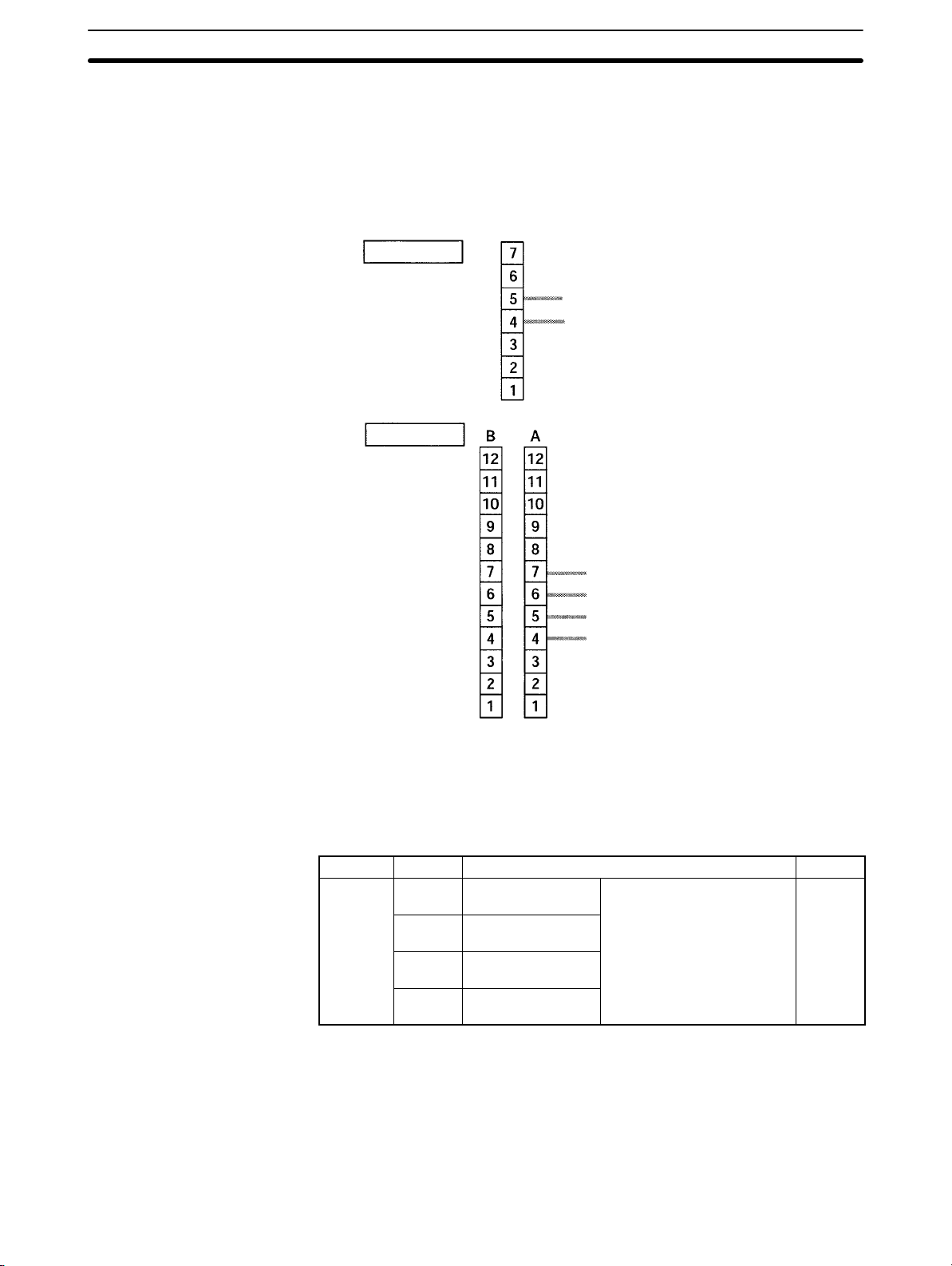
2-2SectionCPM2A/CPM2C High-speed Counters
1: Interrupt input
counter mode)
Note The following examples are for Fujitsu-compatible connectors. Input bit ad-
dresses and connector pin numbers depend on the models. Refer to the CPM2C
Operation Manual (W356) or the CPM2C-S Operation Manual (W377) for de-
tails.
Input terminals
00004: Input interrupt (counter mode) 1
00003: Input interrupt (counter mode) 0
Input connector
(See above note.)
PC Setup
00006: Input interrupt (counter mode) 3
00005: Input interrupt (counter mode) 2
00004: Input interrupt (counter mode) 1
00003: Input interrupt (counter mode) 0
Note Inputs 00006 and 00005 cannot
be used with CPU Units that
have only 10 I/O points.
The following table shows the settings in the PC Setup area related to interrupt
input usage.
Word Bits Function Setting
DM 6628
00 to 03 Interrupt setting for
input 00003
04 to 07 Interrupt setting for
input 00004
08 to 11 Interrupt setting for
input 00005*
12 to 15 Interrupt setting for
input 00006*
0: Normal input
(interrupt input mode or
counter mode)
2: Quick-response input
1
72
Note *Input number 00005 and 00006 cannot be used in CPM2C CPU Units with 10
I/O points and in CPM2C-S CPU Units.
The setting will go into effect when the mode is changed (from PROGRAM to
MONITOR/RUN) or when the power supply is turned ON to the CPM2A/
CPM2C.
Page 94

2-2SectionCPM2A/CPM2C High-speed Counters
(SV)
(PV)
(PV)
Ladder Diagram
Programming
The following table shows the instruction operations related to interrupt input
(counter mode) control.
Instruction Control Operation
(@)INT(89)
(@)INI(61) Change PV Changes the counter’s PV.
(@)PRV(62) Read PV Reads the counter’s PV.
Refresh incrementing
counter SV
Refresh decrementing
counter SV
Mask all interrupts Prohibits all interrupts, including interrupt
Unmask all interrupts Permits all interrupts, including interrupt
Refreshes the counter’s SV and starts the
incrementing count.
Refreshes the counter’s SV and starts the
decrementing count.
inputs, interval timer interrupts, high-speed
counters, etc.
inputs, interval timer interrupts, high-speed
counters, etc.
The functions related to input interrupts (counter mode) are executed according
to the data areas shown in the following table.
Word Bits Name Contents
240 00 to 15 SV area for input interrupt (counter mode) 0
241 00 to 15 SV area for input interrupt (counter mode) 1
242 00 to 15 SV area for input interrupt (counter mode) 2
243 00 to 15 SV area for input interrupt (counter mode) 3
244 00 to 15 PV area for input interrupt (counter mode) 0
245 00 to 15 PV area for input interrupt (counter mode) 1
246 00 to 15 PV area for input interrupt (counter mode) 2
247 00 to 15 PV area for input interrupt (counter mode) 3
Stores the
counter’s set
value
Stores the
counter’s
present value
.
.
.
Refresh Incrementing Counter SV / Refresh Decrementing Counter SV
These functions store the counter’s set values in data areas and refresh them by
means of INT(89). In this way, they start the count operation for interrupt inputs
(counter mode) and they permit interrupts.
Storing Set Values in Data Areas
The counter’s set values are stored in words 240, 241, 242, and 243.
SR 240
SR 241
SR 242
SR 243
SV for interrupt input (count mode) 0: 0000 to FFFF
SV for interrupt input (count mode) 1: 0000 to FFFF
SV for interrupt input (count mode) 2: 0000 to FFFF
SV for interrupt input (count mode) 3: 0000 to FFFF
73
Page 95

Starting the Count Operation and Permitting Interrupts
Incrementing Counter
(@)INT(89)
Interrupt control designation (004: Refresh incrementing counter SV)
004
000
Fixed: 000
C
2
Control data word
Decrementing Counter
(@)INT(89)
003
Interrupt control designation (003: Refresh decrementing counter SV)
000
Fixed: 000
C
2
Control data word
Specify and store 0
2-2SectionCPM2A/CPM2C High-speed Counters
Specify interrupt input (counter mode) 3
Specify interrupt input (counter mode) 2
Specify interrupt input (counter mode) 1
Specify interrupt input (counter mode) 0
0: Refresh SV
1: Do not refresh SV
Note When INT(89) is executed to mask interrupts during counter operation (interrupt
control designation 000), counter operation will be stopped and the counter PV
will be reset. To use the counter again, start the counter operation again as described above.
Change PV
This function refreshes the counter’s present value (PV).
(@)INT(89)
P
Port specifier (100. 102, 102, 103: Interrupt inputs (counter mode) 0 to 3)
002
Control designation (002: Change PV)
C
Change PV data word
2
C
2
Change PV data
Registers the PV data to be changed.
0000 to FFFF
Read PV
This function reads the counter’s present value (PV).
Using an Instruction
74
(@)PRV(62)
P
Port specifier (100. 102, 102, 103: Interrupt inputs (counter mode) 0 to 3)
000
Control designation (000: Read PV)
Word for storing PV
D
D
Read PV data
The PV that is read is stored here.
0000 to FFFF
Page 96

2-2SectionCPM2A/CPM2C High-speed Counters
Using Data Areas
The high-speed counter’s present value (PV) is stored in words SR 244 to
SR 247 as shown below.
Application Example
Explanation
Wiring
SR 244
SR 245
SR 246
SR 247
PV
Interrupt input (counter mode) 0
PV
Interrupt input (counter mode) 1
PV
Interrupt input (counter mode) 2
PV
Interrupt input (counter mode) 3
Words SR 244 to SR 247 are refreshed with every scan, so there may be a discrepancy from the exact PV at any given time.
Words SR 244 to SR 247 cannot be used as work word even when the interrupt
inputs (counter mode) are not used.
When the PV is read by executing PRV(62), words 244 to 247 are refreshed with
the same timing.
Mask/Unmask All Interrupts
For details regarding masking and unmasking all interrupts, refer to 2-1-2 Interrupt Inputs.
In this example, the PV is decremented every time input 00003 is turned ON, and
DM 0000 is incremented by 1 by an interrupt subroutine every 100 times
(64 Hex) that input 00003 is turned ON.
The following diagram shows input wiring in the CPM2A.
Input device
75
Page 97

The following diagram shows input wiring in the CPM2C.
Note The following examples are for Fujitsu-compatible connectors. Input bit ad-
dresses and connector pin numbers depend on the models. Refer to the CPM2C
Operation Manual (W356) or the CPM2C-S Operation Manual (W377) for de-
tails.
Input terminals Input connector
(See above note.)
Input device
2-2SectionCPM2A/CPM2C High-speed Counters
Input device
PC Setup
Programming
15 0
DM 6628 0
ON for 1 cycle at beginning
of operation
0 0 1
Specifies bit 00003 as an interrupt input (counter mode). Inputs
00004 to 00006 are used as ordinary inputs.
(89)
Clears Increment Area (DM 0000).
Decrement counter setting
Counter SV: 64 Hex (100 times)
Stores SV in word 240.
Starts counter with bit 00003 as interrupt input
(counter mode).
Refreshes counter SV (decrement counter).
Always 000.
Specifies bit 00003. (Others are masked.)
76
Executed one time when count is up.
Page 98

2-3SectionCPM1/CPM1A Interrupt Functions
2-3 CPM1/CPM1A Interrupt Functions
This section explains the settings and methods for using the CPM1/CPM1A interrupt functions.
2-3-1 Types of Interrupts
The CPM1/CPM1A has three types of interrupt processing, as outlined below.
Input Interrupts
CPM1/CPM1A PCs have two or four interrupt inputs. Interrupt processing is
executed when one of these inputs is turned ON from an external source.
Interval Timer Interrupts
Interrupt processing is executed by an interval timer with a precision of 0.1 ms.
High-speed Counter Interrupts
The high-speed counter counts pulse inputs to one of CPU bits 00000 to 00002.
Interrupt processing is executed when the count reaches the set value of a builtin high-speed counter.
Interrupt Priority When an interrupt is generated, the specified interrupt processing routine is
executed. Interrupts have the following priority ranking.
Interrupt Program
Precautions
Input interrupts > Interval interrupts = High-speed counter interrupts
When an interrupt with a higher priority is received during interrupt processing,
the current processes will be stopped and the newly received interrupt will be
processed instead. After that routine has been completely executed, then processing of the previous interrupt will be resumed.
When an interrupt with a lower or equal priority is received during interrupt processing, then the newly received interrupt will be processed as soon as the routine currently being processed has been completely executed.
When two interrupts with equal priority are received at the same time, they are
executed in the following order:
Input interrupt 0 > Input interrupt 1 > Input interrupt 2 > Input interrupt 3
Interval interrupts > High-speed counter interrupts
Observe the following precautions when using interrupt programs:
1, 2, 3... 1. A new interrupt can be defined within an interrupt program. Furthermore, an
interrupt can be cleared from within an interrupt program.
2. Another interrupt program cannot be written within an interrupt program.
3. A subroutine program cannot be written within an interrupt program. Do not
write a SUBROUTINE DEFINE instruction, SBN(92), within an interrupt program.
High-speed Counter
Instructions and Interrupts
4. An interrupt program cannot be written within a subroutine program. Do not
write an interrupt program between a SUBROUTINE DEFINE instruction
(SBN(92)) and a RETURN instruction (RET(93)).
Inputs used as interrupts cannot be used as regular inputs.
The following instructions cannot be executed in an interrupt subroutine when
an instruction that controls high-speed counters is being executed in the main
program:
INI(61), PRV(62), or CTBL(63)
77
Page 99

2-3SectionCPM1/CPM1A Interrupt Functions
The following methods can be used to circumvent this limitation:
Method 1
All interrupt processing can be masked while the instruction is being executed.
@INT(89)
100
000
000
INI(61)
000
000
000
@INT(89)
200
000
000
Method 2
Execute the instruction again in the main program.
1, 2, 3... 1. This is the program section from the main program:
@PRV(62)
000
002
DM 0000
LR 0000
CTBL(63)
000
000
DM 0000
RSET LR 0000
2. This is the program section from the interrupt subroutine:
SBN(92) 000
25313
@CTBL(63)
000
000
DM 0000
78
25503
LR
0000
Note 1. Define interrupt routines at the end of the main program with SBN(92) and
RET(93) instructions, just like regular subroutines.
2. When defining an interrupt routine, a “SBS UNDEFD” error will occur during
the program check operation, but the program will be executed normally.
Page 100

2-3-2 Input Interrupts
p
p
(Time until the
)
CPM1A 30CD
CPM1 PCs
2-3SectionCPM1/CPM1A Interrupt Functions
The 10-pt CPU Units (CPM1-10CDR- and CPM1A-10CDR-) have two interrupt inputs (00003 and 00004).
The 20-, 30-, and 40-pt CPU Units (CPM1-20CDR-, CPM1A-20CDR-,
CPM1-30CDR-(-V1), CPM1A-30CDR- and CPM1A-40CDR-) have
four interrupt inputs (00003 to 00006).
There are two modes for input interrupts: input interrupt mode and counter
mode.
10-pt CPU Units
(CPM1-10CDR-)
00003
00004
20- and 30-pt CPU Units
(CPM1-20CDR- and
CPM1-30CDR-(-V1))
00003
00004
00005
00006
CPM1A PCs
10-pt CPU Units
(CPM1A-10CDR-)
Note If input interrupts are not used, use inputs 00003 to 00006 as regular inputs.
24VDC
NC
20-, 30-, and 40-pt CPU Units
(CPM1A-20CDR-,
CPM1A-30CDR-, and
CPM1A-40CDR-)
CPU Unit Input Interrupt
CPM1-10CDR-
CPM1A-10CD-
CPM1-20CDR-
CPM1A-20CD-
CPM1-30CDR-(-V1)
CPM1A-30CD-
CPM1A-40CD-
00003 00
00004 01
00003 00
00004 01
00003 02
00004 03
number
Response time
Interrupt mode Counter mode
0.3 ms max. 1 kHz
(Time until the
interrupt
program is
executed.)
79
 Loading...