

Page 1

Cat. No. W406-E1-09
SYSMAC CS/CJ Series
Loop Control Boards
CS1W-LCB01/LCB05
Process-control CPU Units
CS1D-CPU@@P
(CPU Unit: CS1D-CPU@@H, Loop Controller: LCB05D)
Loop-control CPU Units
CJ1G-CPU42P
(CPU Unit: CJ1G-CPU42H, Loop Controller: LCB01)
CJ1G-CPU43P/44P/45P
(CPU Unit: CJ1G-CPU43H/44H/45H, Loop Controller: LCB03)
OPER ATION M ANUAL
Page 2

Page 3

SYSMAC CS/CJ Series
Loop Control Boards
CS1W-LCB01/LCB05
Process-control CPU Units
CS1D-CPU@@P
(CPU Unit: CS1D-CPU@@H, Loop Controller: LCB05D)
Loop-control CPU Units
CJ1G-CPU42P
(CPU Unit: CJ1G-CPU42H, Loop Controller: LCB01)
CJ1G-CPU43P/44P/45P
(CPU Unit: CJ1G-CPU43H/44H/45H, Loop Controller: LCB03)
Operation Manual
Revised January 2013
Page 4

iv
Page 5

Notice:
r
f
OMRON products are manufactured for use according to proper procedures by a qualified operator
and only for the purposes described in this manual.
The following conventions are used to indicate and classify precautions in this manual. Always heed
the information provided with them. Failure to heed precautions can result in injury to people or damage to property.
!DANGER Indicates an imminently hazardous situation which, if not avoided, will result in death or
serious injury . Additionally, there may be severe property damage.
!WARNING Indicates a potentially hazardous situation which, if not avoided, could result in death or
serious injury . Additionally, there may be severe property damage.
!Caution Indicates a potentially hazardous situation which, if not avoided, may result in minor or
moderate injury, or property damage.
OMRON Product References
All OMRON products are capitalized in this man ual. The w ord “Unit” is also capitalized when it refers to
an OMRON product, regardless of whether or not it appears in the proper name of the product.
The abbreviation “Ch,” which appears in some displays and on some OMRON produc ts, often means
“word” and is abbreviated “Wd” in documentation in this sense.
The abbreviation “PLC” means Programmable Controller. “PC” is used, however, in some Programming Device displa ys to mean Programmable Controller.
Visual Aids
The following headings appear in the left column of the manual to help you locate different types of
information.
OMRON, 2002
All rights reserved. No part of this publication may be reproduced, stored in a retrieval system, or transmitted, in any form, o
by any means, mechanical, electronic, photocopying, recording, or otherwise, without the prior written permission o
OMRON.
No patent liability is assumed with respect to the use of th e information contained herein. Moreo v er, because OMRON is constantly striving to improve its high-quality products, the information contained in this manual is subject to change without
notice. Every precaution has been taken in the preparation of this manual. Nevert heless, OMRON assumes no responsibility
for errors or omissions. Neither is any liability assumed for damages resulting from the use of the information contained in
this publication.
Note Indicates information of particular interest for efficient and convenient opera-
tion of the product.
1,2,3... 1. Indicates lists of one sort or another , such as procedures, checklists, etc.
v
Page 6

About Loop Controllers
Loop Control Types, Functional Elements, and Versions
Loop Controller Types
There are two types of CS/CJ-series Loop Controller: Separate Loop Controllers and Loop Controllers Pre-installed in CPU Units
Loop Controller
type
Separate Separate Loop
Pre-installed in
CPU Unit
Type name Product name Model PLC series and Unit type
Controller
CPU Unit with
Pre-installed
Loop Controller
Loop Control Unit CS1W-LC001 CS-series CPU Bus Unit Loop Controller
Loop Control Board CS1W-LCB01/05 CS-series Inner Board Loop Controller
Process-control
CPU Unit
Loop-control CPU
Unit
Loop Controller Functional Elements
• Separate Loop Controllers consist of only the Loop Contr oller f uncti onal element (i.e., the Loop Controller element).
• CPU Units with Pre-installed Loop Controller consists of a CPU Unit functional element (i.e., the CPU Unit element) and the Loop Controller functional element (i.e., the Loop Controller element).
Versions
The functional elements (i.e., the CPU Unit element and Loop Controller element) have versions.
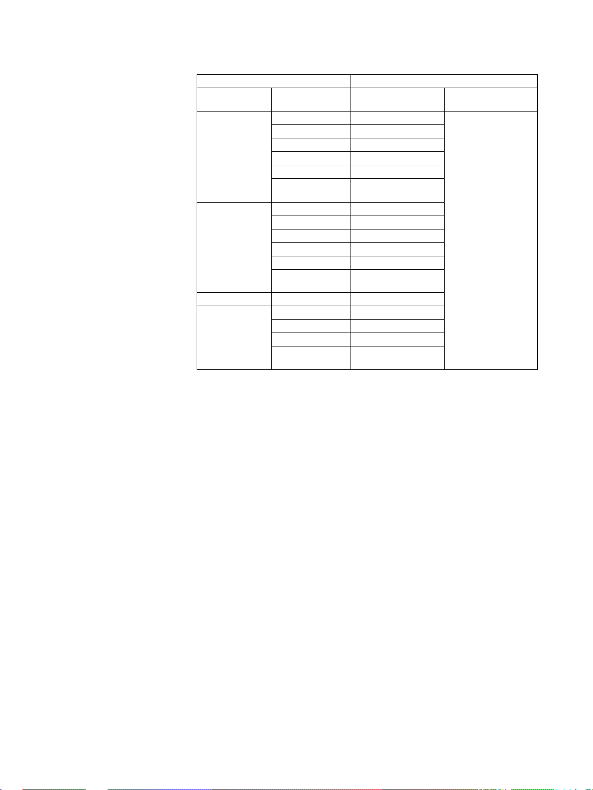
Model Numbers and Functional Elements
The following table lists the Loop Controller product model numbers, the functional element names for the CPU Unit elements and Loop Controller elements, and the versions of the functional elements.
CS1D-CPU@@P A one-Unit Loop Controller consisting of
an Inner Board pre-installed in a CSseries CS1D-H CPU Unit
CJ1G-CPU@@P A one-Unit Loop Controller consisting of
an Inner Board pre-installed in a CJseries CJ1-H CPU Unit
Product name Product model
number
Loop Control
Unit
Loop Control
Board
Process-control
CPU Unit
Loop-control
CPU Unit
CS1W-LC001 Pre-Ver. 2.0 --- LC001 Ver. 2.5
CS1W-LCB01 Ver. 2.0 to Ver.
CS1W-LCB05 LCB05
CS1D-CPU65P --- CS1D-CPU65H Ver. 1.0 or higher LCB05D Ver. 1.0
CS1D-CPU67P CS1D-CPU67H Ver. 1.0 or higher LCB05D
CJ1G-CPU42P --- CJ1G-CPU42H Ver. 3.0 or higher L C B 01 Ver. 2.0 to
CJ1G-CPU43P CJ1G-CPU43H Ver. 3. 0 or higher LC B03
CJ1G-CPU44P CJ1G-CPU44H Ver. 3. 0 or higher LC B03
CJ1G-CPU45P CJ1G-CPU45H Ver. 3. 0 or higher LC B03
Note Only Separate Loop Controllers have a unit version for the product model.
Unit version of
the product
model
(See note.)
3.6
CPU unit element Loop Controller element
CPU Unit
model with
same function-
ality
--- LCB01 V er. 2.0 to
Configuration
Functional ele-
ment unit version
Functional
element
name
Functional
element
Ver. 3.6
Ver. 3.6
CPU Units with Pre-installed Loop Controllers do not have a unit version for
the product model.
vi
Page 7

Notation in this Manual
This manual uses the following notation.
• “Loop Controller” is used as a generic term to refer to the L oop Controllers i n
general.
•“LCB@@” is used to refer to specific Loop Controller functional elements.
For example, the Loop Controller function element in a CS1W-LCB05 Loop
Control Board is the LCB05, so “LCB05” is used to ref er to th e Loop Controller functional element. The Loop Controller function element in a CJ1GCPU44P Loop-control CPU Unit is the LCB03, so “LCB03” is used to refer to
the Loop Controller functional elem ent.
• Model numbers are used to refer to specific Loop Controller models.
In the CX-Process Tool Operation Manual for version 3.2 or lower, functional
element names (LCB@@) are given as “Loop Control Board.” In the CX-Pro-
cess Tool Operation Manual for version 4.0 or higher, simply “LCB@@” is
used.
vii
Page 8
Unit Version Notation on Products
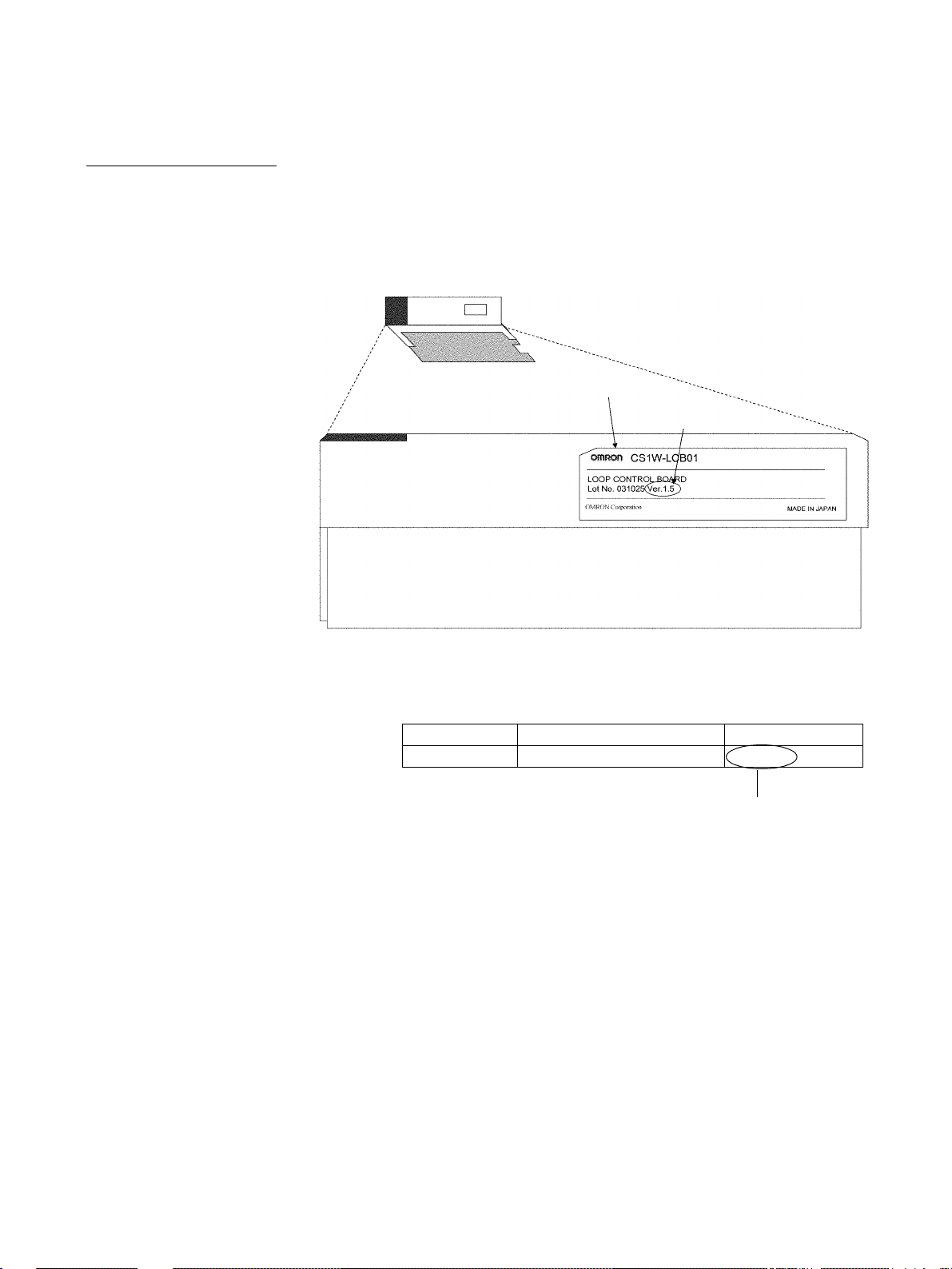
Loop Control Boards A “unit version” has been introduced to manage CPU Units, Special I/O Units,
and Inner Boards in the CS/CJ Series according to differences in functionality
accompanying upgrades. This system applies to Units manufactured since
October 1, 2003. The unit version code is provided on the nameplate of the
product for which unit versions are being managed, as shown below for the
Loop Control Board.
Loop Control Board
Product nameplate
Unit version
Example for unit version 1.5
The CX-Process Tool can be used to co nfirm the un it versions of Loop Control Boards in the Monitor
Run Status Window. After connecting the CX-Process Tool online, select Operation – Monitor Run
Status from the Execute Menu. Confirm the unit version in ITEM099 (MPU/FROM version display)
under from the System Common Block (Block Model 000) in the Monitor Run Status Window.
ITEM Data name Data
099 MPU/FROM version indication V1.50
Version V1.50 and onwards must be indicated.
viii
Page 9
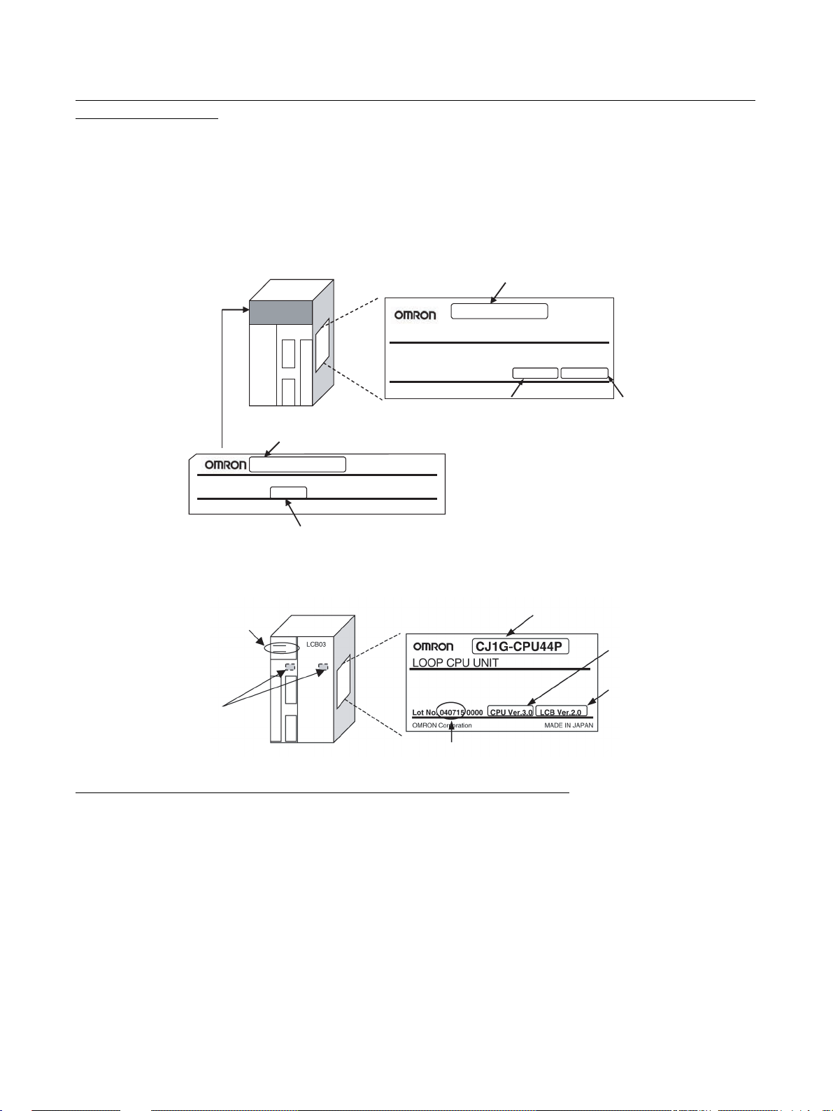
Functional Element Name and Ver sion Code for Process-control CPU Units and Loopcontrol CPU Units
The functional element name and functional element version code for Process-control CPU Units and Loop-control CPU Units are provided on the
nameplate as shown in the following diagrams.
Process-control CPU Units
Note CPU Unit elements for which no version code is provided are pre-Ver. 2.0
CPU Units.
Nameplate on
left side of Unit
LOOP CONTROL BOARD
Lot No. 031025 Ver.1.5
OMRON Corporation
Loop-control CPU Units
Product model and functional
element name
Recommended location for
attaching version label
Process-control CPU Unit
Product nameplate
Lot No. 031001 0000
OMRON Corporation
Functional element name for
Loop Controller element
CS1D-LCB05D
MADE IN JAPAN
Functional element version code for
Loop Controller element
Loop-control CPU Unit
Functional element name for
CPU Unit element
CS1D-CPU67P
PROCESS CPU UNIT
Functional element
version code for the
CPU Unit element
Product nameplate
Lot No.
CPU Ver.1.0 LCB Ver.1.0
MADE IN JAPAN
Functional element
version code for Loop
Controller element
Unit model number
Functional element
version code for
CPU unit element
Functional element
version code for
Loop Controller
element
Confirming CPU Unit Element Versions with Support Software
CX-Programmer version 4.0 can be used to confirm the unit version using
either of the following two methods.
• Using the PLC Information
• Using the Unit Manufacturing Information (This method can also be used for
Special I/O Units and CPU Bus Units.)
Note CX-Programmer version 3.3 or lower cannot be used to confirm unit versions.
ix
Page 10
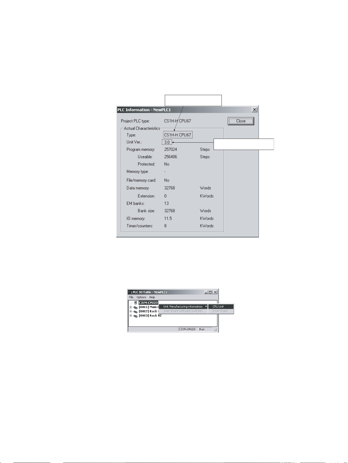
PLC Information
1,2,3... 1. If you know the de vice type and CPU type , select them in the Change PL C
dialog box, go online, and select PLC – Edit – Information from the
menus. If y ou do not know t he de vice type and CPU type , b ut ar e connected directly to the CPU Unit on a serial line, select PLC – Auto Online to
go online, and then select PLC – Edit – Information from the menus.
2. In either case, the following PLC Information Dialog Box will be displayed.
Functional element name
for CPU Unit element
Functional element version
code for CPU Unit element
Unit Manufacturing Information
1,2,3... 1. In the I/O Table Window, right-click and select Unit Manufacturing Infor-
Use the above display to confirm the unit version of the CPU Unit that is
connected online.
mation – CPU Unit.
2. The following Unit Manuf acturing Information Dialog Box will be displa yed.
x
Page 11
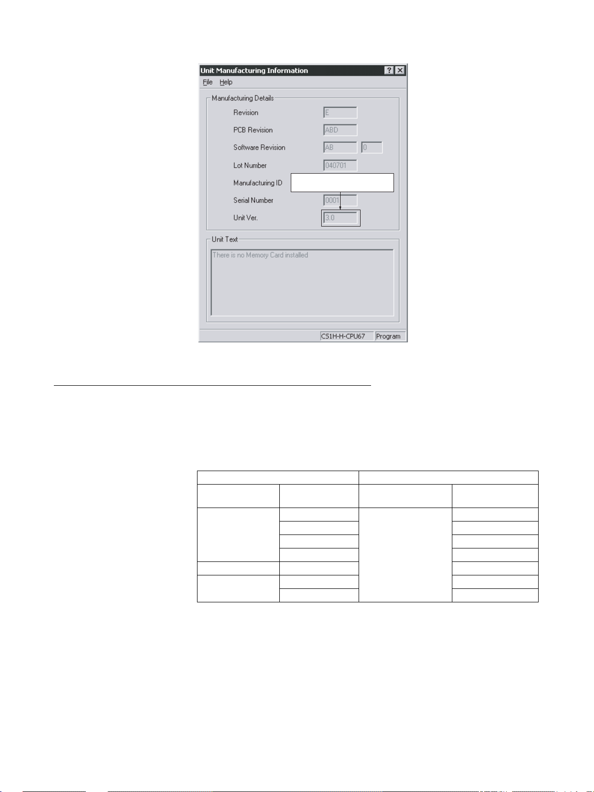
Functional element version
code for CPU Unit element
Use the above displa y to conf irm the unit version of the CPU Unit connected online.
Functional Element Versions and Programming Devices
The Programming Device that suppor ts the functional element version code
must be used to enable all the functions in the corresponding functional element.
Note Upgrading versions is not necessar y if only the basic functions of the CPU
Unit element are required.
CPU Unit Element
Loop Controller Programming Device
Functional
element name
CS1G/H-CPU@@H Pre-Ver. 2.0 --- ---
CS1D-CPU@@H Ver. 1.1 Ver. 4.0 or higher
CJ1G-CPU@@H Ver. 3.0 Ver. 5.0 or higher
Functional
element version
Ver. 2.0 Ver. 4.0 or higher
Ver. 3.0 Ver. 5.0 or higher
Ver. 4.0 Ver. 7.0 or higher
Ver. 4.0 Ver. 7.0 or higher
CX-Process Tool CX-Programmer
(See note.)
xi
Page 12
Loop Controller Element
Loop Controller Programming Device
Functional
element name
LCB01 Ver. 1.0 Not specific ---
LCB05 Ver. 1.0 Not specific
LCB05D Ver. 1.0 Ver. 3.2 or higher
LCB03 Ver. 2.0 Ver. 4.0 or higher
Functional
element version
Ver. 1.5 Ver. 3.2 or higher
Ver. 2.0 Ver. 4.0 or higher
Ver. 3.0 Ver. 5.0 or higher
Ver. 3.5 Ver. 5.2 or higher
Ver. 3.6 Ver. 5.2 or higher
Ver. 1.5 Ver. 3.2 or higher
Ver. 2.0 Ver. 4.0 or higher
Ver. 3.0 Ver. 5.0 or higher
Ver. 3.5 Ver. 5.2 or higher
Ver. 3.6 Ver. 5.2 or higher
Ver. 3.0 Ver. 5.0 or higher
Ver. 3.5 Ver. 5.2 or higher
Ver. 3.6 Ver. 5.2 or higher
CX-Process Tool CX-Programmer
(See note.)
(See note.)
(See note.)
(See note.)
Note When using function component version 3.6 for LCB01, LCB03, or
LCB05, use the CX-One Auto Update function to update the CX-Process Tool Software to version 5.23 or higher.
xii
Page 13

TABLE OF CONTENTS
PRECAUTIONS . . . . . . . . . . . . . . . . . . . . . . . . . . . . . . . . . . . xxiii
1 Intended Audience. . . . . . . . . . . . . . . . . . . . . . . . . . . . . . . . . . . . . . . . . . . . . . . . . . . . . . . . . xxiv
2 General Precautions. . . . . . . . . . . . . . . . . . . . . . . . . . . . . . . . . . . . . . . . . . . . . . . . . . . . . . . . xxiv
3 Safety Precautions . . . . . . . . . . . . . . . . . . . . . . . . . . . . . . . . . . . . . . . . . . . . . . . . . . . . . . . . . xxv
4 Operating Environment Precautions . . . . . . . . . . . . . . . . . . . . . . . . . . . . . . . . . . . . . . . . . . . xxviii
5 Application Precautions. . . . . . . . . . . . . . . . . . . . . . . . . . . . . . . . . . . . . . . . . . . . . . . . . . . . . xxix
6 EC Directives. . . . . . . . . . . . . . . . . . . . . . . . . . . . . . . . . . . . . . . . . . . . . . . . . . . . . . . . . . . . . xxxi
7 Other Applicable Directives . . . . . . . . . . . . . . . . . . . . . . . . . . . . . . . . . . . . . . . . . . . . . . . . . xxxi
SECTION 1
Introduction. . . . . . . . . . . . . . . . . . . . . . . . . . . . . . . . . . . . . . . 1
1-1 Outline . . . . . . . . . . . . . . . . . . . . . . . . . . . . . . . . . . . . . . . . . . . . . . . . . . . . . . . . . . . . . . . . . . 2
1-2 Configuration of Instrumentation System . . . . . . . . . . . . . . . . . . . . . . . . . . . . . . . . . . . . . . . 38
1-3 Specifications. . . . . . . . . . . . . . . . . . . . . . . . . . . . . . . . . . . . . . . . . . . . . . . . . . . . . . . . . . . . . 51
1-4 How to Use Function Blocks for Specific Operations. . . . . . . . . . . . . . . . . . . . . . . . . . . . . . 62
1-5 Basic Procedure for Using the Loop Controller . . . . . . . . . . . . . . . . . . . . . . . . . . . . . . . . . . 66
SECTION 2
Components, Installation, and Wiring . . . . . . . . . . . . . . . . . 71
2-1 Names and Functions of Parts. . . . . . . . . . . . . . . . . . . . . . . . . . . . . . . . . . . . . . . . . . . . . . . . 72
2-2 Installation . . . . . . . . . . . . . . . . . . . . . . . . . . . . . . . . . . . . . . . . . . . . . . . . . . . . . . . . . . . . . . . 74
2-3 Connecting to CX-Process Tool . . . . . . . . . . . . . . . . . . . . . . . . . . . . . . . . . . . . . . . . . . . . . . 76
SECTION 3
Mechanism of the Loop Controller. . . . . . . . . . . . . . . . . . . . 81
3-1 Configuration of Function Blocks . . . . . . . . . . . . . . . . . . . . . . . . . . . . . . . . . . . . . . . . . . . . . 82
3-2 Description of Operation . . . . . . . . . . . . . . . . . . . . . . . . . . . . . . . . . . . . . . . . . . . . . . . . . . . . 91
3-3 Exchanging Data with the CPU Unit. . . . . . . . . . . . . . . . . . . . . . . . . . . . . . . . . . . . . . . . . . . 136
3-4 Exchanging Data Using SCADA an d Other Software . . . . . . . . . . . . . . . . . . . . . . . . . . . . . 157
3-5 Duplex Operation of Loop Controllers . . . . . . . . . . . . . . . . . . . . . . . . . . . . . . . . . . . . . . . . . 167
3-6 Fail-safe Countermeasure Guidelines . . . . . . . . . . . . . . . . . . . . . . . . . . . . . . . . . . . . . . . . . . 171
SECTION 4
Simple Example of Use. . . . . . . . . . . . . . . . . . . . . . . . . . . . . . 175
4-1 Simple Example of Use. . . . . . . . . . . . . . . . . . . . . . . . . . . . . . . . . . . . . . . . . . . . . . . . . . . . .176
SECTION 5
Examples of Function Block Combinations . . . . . . . . . . . . . 183
5-1 Basic Examples of PID Control. . . . . . . . . . . . . . . . . . . . . . . . . . . . . . . . . . . . . . . . . . . . . . . 1 84
5-2 Examples of Applied Control Types . . . . . . . . . . . . . . . . . . . . . . . . . . . . . . . . . . . . . . . . . . . 191
xiii
Page 14

TABLE OF CONTENTS
SECTION 6
How to Use FINS Commands . . . . . . . . . . . . . . . . . . . . . . . . 203
6-1 How to Use FINS Commands. . . . . . . . . . . . . . . . . . . . . . . . . . . . . . . . . . . . . . . . . . . . . . . . 204
6-2 FINS Commands for Loop Controllers. . . . . . . . . . . . . . . . . . . . . . . . . . . . . . . . . . . . . . . . . 206
6-3 Description of FINS Commands . . . . . . . . . . . . . . . . . . . . . . . . . . . . . . . . . . . . . . . . . . . . . . 206
SECTION 7
Errors and Alarm Troubleshooting . . . . . . . . . . . . . . . . . . . 221
7-1 Errors and Alarm Troubleshooting . . . . . . . . . . . . . . . . . . . . . . . . . . . . . . . . . . . . . . . . . . . . 222
7-2 Maintenance. . . . . . . . . . . . . . . . . . . . . . . . . . . . . . . . . . . . . . . . . . . . . . . . . . . . . . . . . . . . . . 238
Appendices
A How to Use the Step Ladder Program Block . . . . . . . . . . . . . . . . . . . . . . . . . . . . . . . . . . . . 243
B How to Use the Sequence Table Block . . . . . . . . . . . . . . . . . . . . . . . . . . . . . . . . . . . . . . . . . 255
Index. . . . . . . . . . . . . . . . . . . . . . . . . . . . . . . . . . . . . . . . . . . . . 277
Revision History . . . . . . . . . . . . . . . . . . . . . . . . . . . . . . . . . . . 281
xiv
Page 15

About this Manual:
This manual describes the installation and operation of the CS-series CS1W-LCB01 and CS1WLCB05 Loop Control Boards, CS1D-CPU@@P Process-control CPU Units, and CJ1G-CPU@@P Loopcontrol CPU Units, and includes the sections described below.
The CS-series CS1W-LCB01 and CS1W-LCB05 Loop Control Boards, CS1D-CPU@@P Process-control CPU Units, and CJ1G-CPU@@P Loop-control CPU Units help you build an instrumentation system
comprising multiple loops. A Loop Control Board is installed as an Inner Board in the CPU Unit of a
CS-series PLC (Programmable Controller).
The CS1W-LCB01 and CS1W-LCB05 Loop Control Boards must be installed in CS1-H CPU Units.
They cannot be used in CS1 CPU Units.
Please read this manual and the other manuals related to the CS1W-LCB01 and CS1W-LCB05 Loop
Control Boards, CS1D-CPU@@P Process-control CPU Units, and CJ1G-CPU@@P Loop-control CPU
Units carefully and be sure you understand the information provided before attempting to install and
operate the products. The manuals used with the CS1W-LCB01 and CS1W-LCB05 Loop Control
Boards, CS1D-CPU@@P Process-control CPU Units, and CJ1G-CPU@@P Loop-control CPU Units
are listed in the follo wing t able. The suffixes have bee n omit ted f ro m the cat alog numbers. Be sure you
are using the most recent version for your area.
Name Contents Cat. No.
SYSMAC CS/CJ Series
CS1W-LCB01, CS1W-LCB05, CS1DCPU@@P, and
CJ1G-CPU@@P
Operation Manuals
SYSMAC CS/CJ Series
CS1W-LCB01, CS1W-LCB05,CS1DCPU@@P, and CJ1G-CPU@@P
Function Block Reference Manual
SYSMAC CX-One FA Integrated Tool
Package
CXONE-AL@@C-V4/AL@@D-V4
CXONE-LT@@C-V4
Setup Manual
SYSMAC CS/CJ Series
CX-Process Tool
Operation Manual
Faceplate Auto-Builde r for NS
Operation Manual
(suffixes omitted)
Describes the basic running of the Loop Control
Boards (excluding detailed descriptions of the
function blocks).
Provides detailed information on the function
blocks.
Provides an overview of the CX-One FA Integrated
Tool and installation procedures.
Describes operation of the CX-Process Tool. W372
Describes operation of the software that generates
NS-series PT projects from a SCADA CSV file output by the CX-Process Tool.
W406
W407
W463
W418
When using CS1D Process-control CPU Units, refer to the following manuals for information on the
CS1D CPU Unit elements.
Name Contents Cat. No.
(suffixes omitted)
SYSMAC CS Series
CS1D-CPU
CS1D-PA/PD
CS1D Duplex System
Operation Manual
@@H, CS1D-DPL01
@@@
Describes the setup and operation of CS1D
Duplex systems.
W405
xv
Page 16

About this Manual, Continued
When using CJ Series Loop-c ontrol CPU Units, refer to the following manuals for infor mation on the
CJ1-H CPU Unit elements.
Name Contents Cat. No.
(suffixes omitted)
SYSMAC CJ Series
Programmable Controllers Operation Manual
CJ1G/H-CPU@@H, CJ1G-CPU@@P,
CJ1MCPU
SYSMAC CS/CJ Series
Programmable Controllers
Programming Manual
CS1G/H-CPU
CS1DCPU@@H, CS1D-CPU@@S,
CJ1G/H-CPU
CJ1M-CPU
SYSMAC CS/CJ/NSJ Series
CJ2H-CPU6
CJ2M-CPU
CS1G/H-CPU
CS1D-CPU@@S, CJ1H-CPU@@H-R,
CJ1G/H-CPU
CJ1M-CPU
NSJ@-@@@@(B)-G5D,
NSJ
Programmable Controllers Instructions Refer-
ence Manual
@@,CJ1G-CPU@@
@@-EV1, CS1G/H-CPU@@H,
@@H, CJ1G-CPU@@P,
@@, CJ1G-CPU@@
@-EIP, CJ2H-CPU6@,
@@, CS1G/H-CPU@@H,
@@-EV1, CS1D-CPU@@H,
@@H, CJ1G-CPU@@P,
@@, CJ1G-CPU@@,
@-@@@@(B)-M3D
Provides an outlines of and describes the
design, installation, maintenance, and other
basic operations for the CJ-series PLCs.
This manual describes programming and
other methods to use the functions of the
CS/CJ-series PLCs.
Provides detailed descriptions of the instructions. When programming, use this manual
together with the manuals for your CPU
Unit.
W393
W394
W474
Section 1 outlines the features and application of the Loop Controllers and provides Loop Controller
specifications.
Section 2 describes the names and functions of parts, and provides other information required to
install and operate Loop Controllers.
Section 3 provides info rmation on the cont rol mech anism, basic operation, exchanging data with other
Units and software, and fail-safe countermeasures for Loop Controllers.
Section 4 describes a simple example of how to use Loop Controllers.
Section 5 describes basic examples of combining function blocks.
Section 6 provides information on how to use FINS commands.
Section 7 provides information on errors that may occur while running of Loop Controllers and guide-
lines for troubl eshooting these errors.
Appendix A describes how to use the Step Ladder Program block on the LCB@@s and Appendix B
describes how to use the Sequence Table block on the LCB@@s.
xvi
Page 17

WARNING
Failure to read and understand the information provided in this manual may result in
personal injury or death, damage to the product, or product failure. Plea se read each
section in its entirety and be sure you understand the information provided in the
section and related sections before attempting any of the procedures or operations
given.
xvii
Page 18

xviii
Page 19

Read and Understand this Manual
Please read and understand this manual before using the product. Please consult your OMRON
representative if you have any questions or comments.
Warranty and Limitations of Liability
WARRANTY
OMRON's exclusive warranty is that the products are free from defects in mat erials and workmanship for a
period of one year (or other period if specified) from date of sale by OMRON.
OMRON MAKES NO WARRANTY OR REPRESENTATION, EXPRESS OR IMPLIED, REGARDING NONINFRINGEMENT, MERCHANTABILITY, OR FITNESS FOR PARTICULAR PURPOSE OF THE
PRODUCTS. ANY BUYER OR USER ACKNOWLEDGES THAT THE BUYER OR USER ALONE HAS
DETERMINED THAT THE PRODUCTS WILL SUITABLY MEET THE REQUIREMENTS OF THEIR
INTENDED USE. OMRON DISCLAIMS ALL OTHER WARRANTIES, EXPRESS OR IMPLIED.
LIMITATIONS OF LIABILITY
OMRON SHALL NOT BE RESPONSIBLE FOR SPECIAL, INDIRECT, OR CONSEQUENTIAL DAMAGES,
LOSS OF PROFITS OR COMMERCIAL LOSS IN ANY WAY CONNECTED WITH THE PRODUCTS,
WHETHER SUCH CLAIM IS BASED ON CONTRACT, WARRANTY, NEGLIGENCE, OR STRICT
LIABILITY.
In no eve nt shall the responsibil ity of OMR ON fo r any act e xcee d the individual price of the product on which
liability is asserted.
IN NO EVENT SHALL OMRON BE RESPONSIBLE FOR WARRANTY, REPAIR, OR OTHER CLAIMS
REGARDING THE PRODUCTS UNLESS OMRON'S ANALYSIS CONFIRMS THAT THE PRODUCTS
WERE PROPERLY HANDLED, STORED, INSTALLED, AND MAINTAINED AND NOT SUBJECT TO
CONTAMINATION, ABUSE, MISUSE, OR INAPPROPRIATE MODIFICATION OR REPAIR.
xix
Page 20

Application Considerations
SUITABILITY FOR USE
OMRON shall not be responsible for conformity with any standards, codes, or regulations that apply to the
combination of products in the customer's application or use of the products.
At the customer's request, OMRON will provide applicable third party certification documents identifying
ratings and limitations of use that apply to the products. This information by itself is not sufficient for a
complete determination of the suitability of the products in combination with the end product, machine,
system, or other application or use.
The following are some examples of applications for which particular attention must be given. This is not
intended to be an e xhaustive list of all possible uses of the products, nor is it inte nded to imply that the uses
listed may be suitable for the products:
• Outdoor use, uses involving potential chemical contamination or electrical interference, or conditions or
uses not described in this manual.
• Nuclear energy control systems, combustion systems, railroad systems, aviation systems, medical
equipment, amusement machines, vehicles, safety equipment, and installations subject to separate
industry or government regulations.
• Systems, machines, and equipment that could present a risk to life or property.
Please know and observe all prohibitions of use applicable to the products.
NEVER USE THE PRODUCTS FOR AN APPLICATION INVOLVING SERIOUS RISK TO LIFE OR
PROPERTY WITHOUT ENSURING THAT THE SYSTEM AS A WHOLE HAS BEEN DESIGNED TO
ADDRESS THE RISKS, AND THAT THE OMRON PRODUCTS ARE PROPERLY RATED AND
INSTALLED FOR THE INTENDED USE WITHIN THE OVERALL EQUIPMENT OR SYSTEM.
PROGRAMMABLE PRODUCTS
OMRON shall not be responsible for the user's programming of a programmable pr oduct, or any
consequence thereof.
xx
Page 21

Disclaimers
CHANGE IN SPECIFICATIONS
Product specifications and accessories may be changed at any time based on improvements and other
reasons.
It is our practice to change model numbers when published ratings or features are changed, or when
significant construction changes are made. However, some specifications of the products may be changed
without any notice. When in doubt, sp ecial model numbers may be assigned to fix or establish key
specifications for your application on your request. Please consult with your OMRON represe ntative at any
time to confirm actual specifications of purchased products.
DIMENSIONS AND WEIGHTS
Dimensions and weights are nominal and are not to be used for manufacturing purposes, even when
tolerances are shown.
PERFORMANCE DATA
Perf ormance data given in this manual is provided as a guide for the user in determining suitability and does
not constitute a warranty. It may represent the result of OMRON's test conditions, and the users must
correlate it to actual application requirements. Actual performance is subject to the OMRON Warranty and
Limitations of Liability.
ERRORS AND OMISSIONS
The information in this manual has been ca refully checked and is believed to be accurate; however, no
responsibility is assumed for clerical, typographical, or proofreading errors, or omissions.
xxi
Page 22

xxii
Page 23

PRECAUTIONS
This section provides general precautions for using the Programmable Controller (PLC) and related devices.
The information contained in this section is important for the safe and reliable application of the Programmable
Controller. You must read this section and understand the information contained before attempting to set up or
operate a PLC system.
1 Intended Audience . . . . . . . . . . . . . . . . . . . . . . . . . . . . . . . . . . . . . . . . . . . . . xxiv
2 General Precautions . . . . . . . . . . . . . . . . . . . . . . . . . . . . . . . . . . . . . . . . . . . . xxiv
3 Safety Precautions. . . . . . . . . . . . . . . . . . . . . . . . . . . . . . . . . . . . . . . . . . . . . . xxv
4 Oper a ting Environment Precautions . . . . . . . . . . . . . . . . . . . . . . . . . . . . . . . . xxviii
5 Application Precautions . . . . . . . . . . . . . . . . . . . . . . . . . . . . . . . . . . . . . . . . . xxix
6 EC Directives . . . . . . . . . . . . . . . . . . . . . . . . . . . . . . . . . . . . . . . . . . . . . . . . . xxxi
7 Other Applicable Directives . . . . . . . . . . . . . . . . . . . . . . . . . . . . . . . . . . . . . . xxxi
xxiii
Page 24

Intended Audience 1
1 Intended Audience
This manual is intended for the following personnel, who must also have
knowledge of electrical systems (an elec trical engineer or the equivalent) and
knowledge about instrumentation systems.
• Personnel in charge of installing FA systems
• Personnel in charge of designing FA system s
• Personnel in charge of managing FA systems and facilities
2 General Precautions
The user must operate the product according to the performance specifications described in the operation manuals.
Before using the product under conditions which are not described in this
manual or applying the product to nuclear control systems, railroad systems,
aviation systems, vehicles, combustion systems, medical equipment, amusement machines, safe ty equipment, petrochemical plants, and other systems,
machines, and equipment that may have a serious influence on lives and
property if used improperly, consult your OMRON representative.
Make sure that the ratings and performance characteristics of the product are
sufficient for the systems, machines, and equipment, and be sure to provide
the system, machines and equipment with double safety mechanism.
This manual provides information for running CS1W-LCB01 and CS1WLCB05 Loop Control Boards, CS1D-CPU@@P Process-control CPU Unit, and
CJ1G-CPU@@P Loop-control CPU Unit. Be sure to read this manual before
attempting to use these products and related software (CX-Process Tool) and
keep this manual close at hand for reference during running.
!WARNING It is extremely important that a PLC and all PLC Units be used for the speci-
fied purpose and under the specified conditions, especially in a pplications that
directly or indirectly affect human life. You must consult with your OMRON
representative before applying a PLC System to the above-mentioned applications.
xxiv
Page 25

Safety Precautions 3
3 Safety Precautions
!WARNING Do not attempt to take any Unit or Board apar t while power is being supplied.
Doing so may result in electric shock.
!WARNING Do not touch live terminals. Electric shock will result.
!WARNING Provide safety measures in external circuits (i.e., not in the Programmable
Controller), including the following items, to ensure safety in the system if an
abnormality occurs due to malfunction of the PLC or another external factor
affecting the PLC operation. Not doing so may result in serious accidents.
• Emergency stop circuits, interlock circuits, limit circuits, and similar safety
measures must be provided in external control circuits.
• When using a CS1D-CPU@@P Process-control CPU Unit, the CS1D
Duplex System will stop operating and all outputs will be turned OFF in
the following cases:
• The self-diagnostic function detected errors at the same time in both
the active side (CPU Unit or Loop Controller) and the standby side
(CPU Unit or Loop Controller).
• A SEVERE F AILURE ALARM (FALS) instruction is executed and generated fata l errors at the same time in both the a ctive CPU Unit and t he
standby CPU Unit.
• The self-diagnostic function detected an error while operating in simplex mode or performing duplex initialization in duplex mode.
• A SEVERE FAILURE ALARM (FALS) instruction was executed and
generated a fatal error while operating in simplex mode or performing
duplex initialization in duplex mode.
Unexpected operation, however, may still occur for errors in the I/O control section, errors in I/O memory, and other errors that cannot be
detected by the self-diagnosis function. As a countermeasure for all such
errors, external safety measures must be provided to ensure safety in the
system.
• When a CS1W-LCB01 or CS1W-LCB05 Loop Control Board is mounted
in a CS1-H CPU Unit, the CPU Unit will stop operating and all outputs will
be turned OFF if the self-diagnostic function detected an error or a
SEVERE FAILURE ALARM (FALS) instruction was executed. As a countermeasure for such errors, external safety measures must be provided to
ensure safety in the system.
• The PLC outputs may remain ON or OFF due to depos ition or burning o f
the output relays or destr uction of the output transistors. As a countermeasure for such problems, external safety measures must be provided
to ensure safety in the system.
• When the 24-V DC output (service power supply to the PLC) is overloaded or short-circuited, the voltage may drop and result in the outputs
being turned OFF. As a countermeasure for such problems, external
safety measures must be provided to ensure safety in the system.
!WARNING Check the following items before starting to run the Loop Controller:
xxv
Page 26

Safety Precautions 3
• Do not allow the bank of the EM Area wit h the number specified f or a llocation to the HMI (human-machine interface) data to overlap with any other
area used by the CPU Unit or other Units. The block allocated for the HMI
is specified in ITEM 050 (EM Area Bank Allocated for HMI Memory = 0 to
12) of the System Common block (Block Model 000). If areas overlap, the
system may operate in an unexpected manner, which may result in injury.
• Do not allow the area to which user link table data is written to overlap
with any other area used by the CPU Unit or other Units. If areas over lap,
the system may operate in an unexpected manner, which may result in
injury.
• When using a user link table to write bit data to I/O memor y in the CPU
Unit. Never allow ladder programming or communications processes in
the CPU Unit to write to any bits in the words in which bits are written from
a user link table. Depending on the timing, any attempts to write to these
words from ladder programming or communications processes may be
ignored. Example: If tag A in a user link table writes to bit 00 of W000 and
an OUT instruction in the ladder program in the CPU Unit write to bit 01 of
W000, the write from the ladder program may be ignored.
• Analog Input/Output Units used in combination with the Loop Controller
must be mounted correctly, and the unit number set on the front panel of
the Analog Input/Output Unit must match the unit number set on the Field
Terminal block. If the unit numbers do not match, input/output (read/write)
is performed on the data of another Special I/O Unit (whose unit number
is set on the Field Terminal block).
• The defaults of the System Common block on the Loop Controller must
be set correctly.
• Always stop the operation of the Loop Controller before converting any of
the EM Area to file memory. If any part of the EM Area that is being used
by the Loop Controller for the s is converted to file memory during Board
operation, the system may operate in an unexpected manner, which may
result in injury.
!WARNING Do not use battery-fr ee operation for the CS1-H CPU Unit or the CPU Unit
element of a Process-control CPU Unit or Loop-control CPU Unit. If batteryfree operation is used for the CPU Unit or CPU Unit element, the contents of
the EM Area will not be stable when the power supply is turned ON, possibly
causing illegal values in the HMI data in the Loop Controller.
!WARNING Do not perform processing in such a way that the Loop Controller and CPU
Unit perform writing on identical I/O memory addresses allocated to an contact output or analog output to an e xternal Unit. If writing is perf ormed on identical addresses, the externally connected load may act unexpectedly and
cause injury.
xxvi
Page 27
Safety Precautions 3
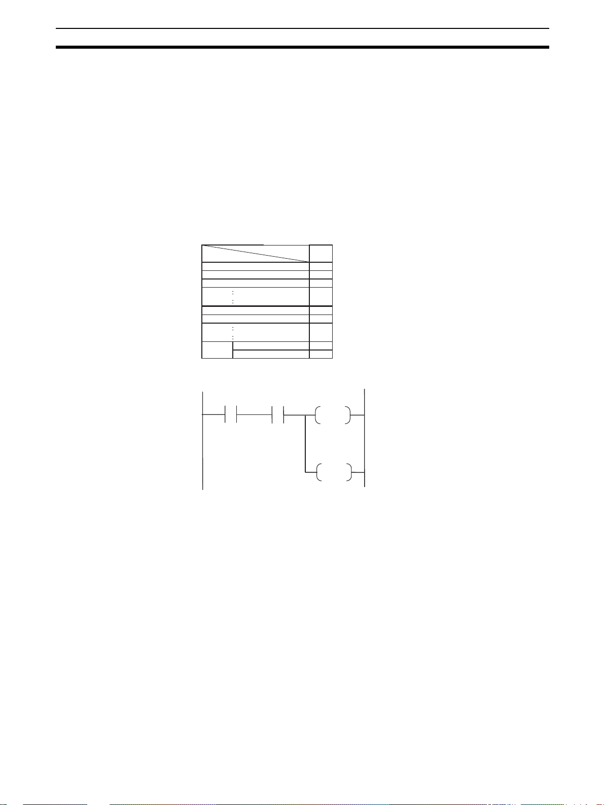
!WARNING The Loop Controller will automatically start using a cold star t even if the star-
tup mode is set to a hot star t if the power is turned ON after being OFF for
24 hours or longer. If this happens, the auto/manual setting for the Control
Block will be set to manual mode (MV=0%) and the remote/local setting will
be set to local. To automatically switch to auto mode at th e same time as starting operation after the power is turned ON after being OFF for 24 hours or
longer, the ladder diagrams in the Sequence Table or Step Ladder Program
blocks must be programmed as follows (same as the procedure for switching
to remote operation):
Processing: ITEM 086 (Auto/Manual switch) of the Basic PID block or
Advanced PID block is set to 1 using ITEM019 (Run Start Flag) and ITEM017
(cold start in progress) of the System Common block as the input conditions.
Sequence Table
Signal
000.019 Y
000.017 Y
001.086 Y
000.019 N
STEP
STEP
Run Start flag
Cold start in progress
A/M
Run Start flag
THENNEXT
ELSE
00
Step Ladder Program
000-019 000-017
Run Start
flag
Cold start in
progress
S
A/M
000-019
R
Run Start
flag
PID1 is Auto at power ON.
For details on hot and cold start operations, refer to 3-2-3 Details of Hot Start,
Cold Start and Stop State.
!WARNING When using the CS1D-CPU@@P Process-control CPU Unit, both the CPU
Unit’s cycle time and the Loop Controller’s operation cycle will be temporarily
longer than normal during duplex initialization (i n duple x mode). The extended
cycle time and operation cycle may temporarily worsen the control characteristics, so verify the system’s operation in test runs before actually running the
system.
!Caution When downloading a sequence table for the Loop Control Board (version 1.5
or higher) that has been edited online with the CX-Process Tool version 3.2 or
higher, confirm that the system will operate normally with the edited
sequence. If the sequence is not suitable for operation, unexpected operation
may result.
xxvii
Page 28

Operating Environment Precautions 4
!Caution Confirm in advance the conditions at an y node for which the sequence table is
being edited over a Controller Link or Ethernet network. Not doing so may
result in unexpected operation.
!Caution Do not use the HMI function to write a value that is ou tside of the data range
shown in the ITEM list in the Function Block Reference Manual (Cat. No.
W407) to the receive area (CPU Unit to Loop Controller) in the EM Area. Writing an out-of-range value can result in unexpected operation by the controlled
machine or equipment.
!Caution When executing calibration functions, the MV (manipulated variable) will be
changed when the PV (process value) is changed in the control block. Therefore, before executing this function, make sure that the equipment will be safe
even if the MV changes by setting pseudo-inputs. Otherwise, unexpected
equipment operation may result, causing a serious accident.
4 Operating Environment Precautions
4-1 CS1D-CPU@@P Process-control CPU Unit Precautions
• Normal operation will be possible only if the CS1D-CPU@@P Processcontrol CPU Unit is used in the combination in which it was shipped. Normal operation may not be po ssible if the CS1D-CPU@@P Process-control
CPU Unit is used in any other combination. Therefore, do not remove the
Loop Controller component from the CPU Unit. Always replace the entire
CS1D Process-control CPU Unit as on e Unit even if only the Loop Controller or CPU Unit has failed.
• The CS1D CPU Unit’s cycle time and the Loop Controller component’s
LCB load rate are different in duplex mode and simplex mode. Verify the
system’s oper ation in bo th modes in trial opera tion before actually running
the system.
• When replacing a CS1D Process-control CPU Unit while powe r is supplied to the PLC, always switch the DPL Unit’s CPU U SE/NO USE switch
to “NO USE.” Removing the CS1D Process-control CPU Unit with the
switch set to “USE” (power supplied) may damage the CPU Duplex Backplane, CS1D CPU Unit, DPL Unit, and Loop Controller component of the
Process-control CPU Unit.
4-2 CS1W-LCB01/CS1W-LCB05 Loop Control Board Precautions
Do not use a CS1W-LCB01 or CS1W-LCB05 Loop Control Board in any CPU
Unit other than the CS1-H.
• If a CS1W-LCB01 or CS1W-LCB05 Loop Control Board is used in a CS1
CPU Unit, a non-fatal INNER Board error will occur and the Loop Control
Board will not operate. (The CPU Unit itself will be able to operate.)
• If a CS1W-LCB01 or CS1W-LCB05 Loop Control Board is used in a
CS1D CPU Unit, a fatal INNER Board error will occur. (In this case, neither the Loop Control Board nor the CPU Unit will operate.)
• Loop Control Boards before version 1.5 cannot be used with CS1DCPU@@S CS1D CPU Units for Single-CPU Systems.
• Do not connect pin 6 (+5 V power supply line) of the RS-232C port on the
CPU Unit to any external device except the CJ1W-CIF11 RS-422A
Adapter or NT-AL001 RS-232C/RS-422A Adapter. Doing so may damage
the external device or Loop Control Board.
xxviii
Page 29

Application Precautions 5
4-3 Precautions for All Loop Control Boards, Process-control CPU
Units, and Loop-control CPU Units
!Caution Do not operate the control system in the following places:
• Locations subject to direct sunlight
• Locations subject to temperature or humidity outside the range specified
in the specifications
• Locations subject to condensation as the r esult of severe changes in temperature
• Locations subject to corrosive or flammable gases
• Locations subject to dust (especially iron dust) or salts
• Locations subject to exposure to water, oil, or chemicals
• Locations subject to shock or vibration
!Caution Take appropriate and sufficient countermeasures when installing systems in
the following locations:
• Locations subject to static electricity or other forms of noise
• Locations subject to strong electromagnetic fields
• Locations subject possible exposure to radioactivity
• Locations close to power supplies
!Caution The operating environment of the PLC System can have a large effect on the
longevity and reliability of the system. Improper operating environments can
lead to malfunction, failure, and other unforeseeable problems with the PLC
System. Be sure that the operating environment is within the specified conditions at installation and remains within the specified conditions during the life
of the system.
5 Application Precautions
Observe the following precautions when using the PLC.
!WARNING Always heed these precautions. Failure to abide by the following precautions
could lead to serious or possibly fatal injury.
• Always turn OFF the power to the PLC before attempting any of the following. Not turning OFF the power may result in malfunction or electric
shock.
• Mounting or dismounting I/O Units, including Inner Boards
• Assembling the Racks
• Setting DIP switches or unit number setting switches
• Connecting or wiring the cables
• Connecting or disconnecting the connectors
!Caution Failure to abide by the following precautions could lead to faulty operation of
the PLC or the system, or could damage the PLC or PLC Units. Always heed
these precautions.
xxix
Page 30

Application Precautions 5
• If the power supply is turned OFF while function block data is being
backed up from RAM to flash memory, the backup will not be completed
normally. If the power supply is turned back ON within 24 hours, however,
the super capacitor will have held the RAM data. The backup operation
will restart when power is turned ON and operation will start when the
backup has been completed. If the power supply is turned OFF for more
than 24 hours, however, RAM data will be lost and operation will be
started with the data that was previously saved to flash memory. If this
happens, the Cold Start Auto-execution Flag (A35807) will turn ON to
show that the previous data has been used. Use this bit in programming
to take whatever steps are necessary, such as downloading the most
recent function block data.
• To hold analog outputs o r contact outp uts at spec ific values (for example,
maximum value or minim um v alue ) when the Loop Controller has stop ped
running, create a Step Ladd er Program on the CPU Unit so that each of
the allocated bits on the Analog Output Unit or Contact Output Unit are
set to a specific value taking the N.C. condition of the Loop Controller
Running flag (A35801) as the input condition.
• When a fatal error occurs on the CPU Unit (including execution of the
FALS instruction), the Loop Controller also stops running. To hold the
analog output to the previous value before the stop occurred, and to set
the analog output to either the minimum value or maximum value, use the
output hold function of the Analog Output Unit or Analog Input/Output
Unit.
• Before turning ON the power to the PLC, make sure that the facilities are
safe.
• The analog output values and contact outputs from the Loop Controller
are updated at the same time that the power to the PLC is turned ON
regardless of the operation mode of the CPU Unit (including the PROGRAM mode). (Internally, the analog output values and contact outputs
are sent via the CPU Unit to the Basic I/O Unit and Analog Output Unit.)
• The Loop Controller itself does not have a human-machine interface. So,
an external interface such as SCADA software must be provided.
• Fail-safe measures must be taken by the customer to ensure safety in the
event of incorrect, missing, or abnormal signals caused by broken signal
lines, momentary power interruption s or other causes.
• Before touching the PLC, be sure to first touch a grounded metallic object
in order to discharge any static build-up. Otherwise, it might result in a
malfunction or damage.
• Take appropriate measures to ensure that the specified power with the
rated voltage and frequency is supplied. Be particularly careful in places
where the power supply is unstable. An incorrect power supply may result
in malfunction.
• Do not attempt to disassemble, repair, or modify any Units or Boards.
• Leave the dust-protection label attached to the top Unit when wiring.
Removing the label may result in malfunction.
• Remove the label afte r the co mpletio n of wiring to ensure proper heat dissipation. Leaving the label attached may result in malfunction.
• Check the user program for proper execution before actually running it on
the Unit or Board. Not checking the program may result in an unexpected
operation.
xxx
Page 31

EC Directives 6
• Double-check all the wiring before turning ON the power supply. Incorrect
wiring may result in burning.
• Tighten the PLC Backplane mounting screws, terminal block screws, and
cable (connector) screws to the torque specified in user manuals.
• Confirm that no adverse effect will occur in the system before attempting
any of the following:
• Changing the operating mode of th e PLC
• Force-setting/force-resetting of any contact in memory
• Changing the present value or any set value in memory
6 EC Directives
CS-series products confirm to EC Directives. For th e system to conf o rm to EC
Directives, however, the following precautions must be adhered to.
• CS-series Units must be installed within control panel.
• Use reinforced insulation of double insulation for the DC power supplies
used for the I/O power supplies.
• CS-series products that meet EC Directives also meet the Common
Emission Standard (EN61000-6-4). The measure necessary to ensure
that standards, such as the radiated emission standard (10 m), are met,
however, will vary depending on the overall configuration of the control
panel, the other devices to the control panel, and wiring. You must therefore confirm that EC Directives are me t for the overall machine or device.
7 Other Applicable Directives
Applicable Directives
• EMC Directive
• Low Voltage Directive
EMC and Low Voltage Directives
EMC Directive
In order that OMRON products can be used with an y machine ry and in combination with other manufacturer's equipment, the products themselves are
designed to comply with EMC standards (see Note), so that the assembled
machinery or device can then also easily comply with EMC standards.
Even if machinery and equipment complies with EMC standards before
assembly, this compliance may change depending on the device, the configuration of the control panel, and wiring, so OMRON cannot guarantee that a
particular system complies with the directive. You must therefore confir m that
EMC Directives are met for the overall machine or device.
Note EMC: One directive relating to Electro-Magnetic Compatibility
EMS: Electro-Magnetic Susceptibility standard EN6100-6-2
EMI: Electro-Magnetic Interference standard EN61000-6-4
Common Emission Standard EN61000-6-4, radiated emission standard
(10 m)
xxxi
Page 32

Other Applicable Directives 7
Low Voltage Directive
The Low Voltage Directive provides that necessary safety standards are guaranteed for devices operating at voltages of 50 to 1,000 V AC or 75 to 1,500 V
DC to comply with EN61131-2.
xxxii
Page 33

SECTION 1
Introduction
This section outlines the features and application of the Loop Controllers and provides Loop Controller specifications.
1-1 Outline. . . . . . . . . . . . . . . . . . . . . . . . . . . . . . . . . . . . . . . . . . . . . . . . . . . . . . . 2
1-1-1 Outline . . . . . . . . . . . . . . . . . . . . . . . . . . . . . . . . . . . . . . . . . . . . . . . 2
1-1-2 Features. . . . . . . . . . . . . . . . . . . . . . . . . . . . . . . . . . . . . . . . . . . . . . . 5
1-1-3 LCB01/05 Version 1.5 Upgrade Information. . . . . . . . . . . . . . . . . . 7
1-1-4 LCB01/05 Version 2.0 Upgrade Information. . . . . . . . . . . . . . . . . . 9
1-1-5 LCB01/03/05 Version 3.0 Upgrade Information . . . . . . . . . . . . . . . 10
1-1-6 Upgraded Functions for LCB01/05 and LCB03 Version 3.5 . . . . . . 12
1-1-7 Upgraded Functions for LCB01/05 and LCB03 Version 3.6 . . . . . . 13
1-1-8 Basic System Configuration . . . . . . . . . . . . . . . . . . . . . . . . . . . . . . . 13
1-1-9 Application Examples. . . . . . . . . . . . . . . . . . . . . . . . . . . . . . . . . . . . 14
1-1-10 Loop Controller Mechanism. . . . . . . . . . . . . . . . . . . . . . . . . . . . . . . 17
1-1-11 Overall Mechanism of Data Exchange. . . . . . . . . . . . . . . . . . . . . . . 21
1-1-12 Internal Mechanism of Loop Controll er s . . . . . . . . . . . . . . . . . . . . . 23
1-1-13 List of Function Blocks . . . . . . . . . . . . . . . . . . . . . . . . . . . . . . . . . . 25
1-1-14 Differences between Loop Control Units and Boards . . . . . . . . . . . 32
1-1-15 Version Upgrade Information. . . . . . . . . . . . . . . . . . . . . . . . . . . . . . 36
1-2 Configuration of Instrumentation System. . . . . . . . . . . . . . . . . . . . . . . . . . . . 38
1-2-1 Mounting Location. . . . . . . . . . . . . . . . . . . . . . . . . . . . . . . . . . . . . . 38
1-2-2 Determining the System Configuration . . . . . . . . . . . . . . . . . . . . . . 40
1-2-3 Description of Basic System Configuration . . . . . . . . . . . . . . . . . . . 45
1-3 Specifications . . . . . . . . . . . . . . . . . . . . . . . . . . . . . . . . . . . . . . . . . . . . . . . . . 51
1-3-1 General Specifications . . . . . . . . . . . . . . . . . . . . . . . . . . . . . . . . . . . 51
1-3-2 Specifications . . . . . . . . . . . . . . . . . . . . . . . . . . . . . . . . . . . . . . . . . . 51
1-3-3 Function Specifications . . . . . . . . . . . . . . . . . . . . . . . . . . . . . . . . . . 53
1-3-4 Outline of PID Block Specifications . . . . . . . . . . . . . . . . . . . . . . . . 57
1-3-5 Software Specifications . . . . . . . . . . . . . . . . . . . . . . . . . . . . . . . . . . 60
1-4 How to Use Function Blocks for Specific Operations . . . . . . . . . . . . . . . . . . 62
1-5 Basic Procedure for Using the Loop Controller . . . . . . . . . . . . . . . . . . . . . . . 66
1
Page 34

Outline Section 1-1
1-1 Outline
1-1-1 Outline
Var ious process operations, including PID control, can be performed for up to
500 blocks with the LCB05 and LCB05D, up to 300 blocks with th e LCB03, or
up to 50 blocks with the LCB01. (See note.) Process operations include basic
logic sequence control and step-progression control. The Loop Controller can
also be used to implement an alarm/monitor terminal on a computer without
using PID control functions.
Note The maximum number of control loops is determined by the operation cycle.
In most cases, such as when each loop consists of an Ai4 Terminal, a Segment Linearizer, a Basic PID, and an Ao4 Terminal block the maximum number of control loops would be as shown in the following tables.
Loop Control Boards
CS1W-LCB01 and CS1W-LCB05 (LBC01/05)
Operation cycle Maximum number of loops
0.01 s 20 loops
0.02 s 35 loops
0.05 s 70 loops
0.1 s 100 loops
0.2 s 180 loops
0.5 s 250 loops
1 s 250 loops
2 s 250 loops
Process-control CPU Units
CS1D-CPU@@P (LCB05D)
Operation cycle Maximum number of loops
0.1 s 80 loops
0.2 s 140 loops
0.5 s 250 loops
1 s 250 loops
2 s 250 loops
Loop-control CPU Units
CJ1G-CPU43P/44P/45P (LCB03)
Operation cycle Maximum number of loops
0.01 s 20 loops
0.02 s 35 loops
0.05 s 70 loops
0.1 s 100 loops
0.2 s 150 loops
0.5 s 150 loops
1 s 150 loops
2 s 150 loops
2
Page 35

Outline Section 1-1
CJ1G-CPU42P (LCB01)
Operation cycle Maximum number of loops
0.01 s 20 loops
0.02 s 25 loops
0.05 s 25 loops
0.1 s 25 loops
0.2 s 25 loops
0.5 s 25 loops
1 s 25 loops
2 s 25 loops
The Loop Control Boards, Process-control CPU Units, and Loop-control CPU
Units have no external I/O functions. So, they must be used in a pair with a
Unit having an external interface, such as an Analog I/O Unit or Basic I/O Unit.
The Loop Controller exchanges data with the Unit having the external interface via the CPU Unit I/O memory.
You can achieve all functions (operation functions/designation of field
input/output) simply by combining Control blocks, Operation blocks, and other
function blocks. This allows you to easily build a professional instrumentation
system on your PLC (Programmable Controller).
The following f unctions can be achieved by function blocks:
Internal Operations • Control and operation blocks (500 function blocks max. for LCB05 and
LCB05D (See note.), 300 function blocks max. for LCB03, or 50 function
blocks max. for LCB01): 2-position ON/OFF, Basic PID, Advanced PID,
Ratio Setting, Alarm/Signal Restrictions/Hold, Arithmetic (addition, subtraction, multiplication and division), Functions (Square Root, Absolute
Value, Segment Linearizer, etc.), Time Functions (Lead/Delay, Dead
Time, Ramp Program, etc.), Pulse Train Operation (Accumulator), Signal
Selection/Switching (Rank Selector, Constant Selector, etc.), Sequential
Control (Timers, Counter, etc.)
Note Only 100 function blocks can be used on the LCB05 and LCB05D
if Fuzzy Logic, Arithmetic Operation, or Time Sequence Data Statistics blocks are used.
• External controllers (32 function blocks max.):
ES100X Controller Terminal (Cannot be used on the CS1D-CPU@@P
and CJ1G-CPU@@P.)
• Logic sequence/step progression control (200 function blocks max. for
LCB03, LCB05, and LCB05D, 20 blocks max. for LCB01. 2,000 commands in total.):
Step Ladder Program and sequence table (LCB05 and LCB05D only)
External I/O • Each of the points on the Analog I/O Unit and Basic I/O Unit is read and
written by the Field Terminal block (max. 80 function blocks).
• Specified contacts or analog data in the CPU Unit I/O memo ry is read and
written by user link tables.
• Data for Control, Operation, and External Controller blocks can be read
and written for SCADA software using the HMI function.
Note The CMND instruction can be executed in the ladder program in the CPU Unit
to send FINS commands to the Loop Controller to read and write function
block data.
3
Page 36

Outline Section 1-1
Loop Control Boards Loop Control Boards (CS1W-LCB01 and CS1W-LCB05) are classified as CS-
series Inner Boards. The CS1W-LCB01 and CS1W-LCB05 Loop Control
Boards must be mounted in a CS1-H CPU Unit. (They will not operate and
cannot be used in a CS1 CPU Unit.)
Loop Control Boards before version 1.5 cannot be used with CS1D-CPU@@S
CS1D CPU Units for Single-CPU Systems.
The following table shows available Loop Control Board models.
Model Mountable
PLCs
CS1W-LCB01 CS1-H CPU
CS1W-LCB05 500 blocks max. Supported 200 blocks max.
Units
Duplex Mode Number of control
and operation blocks
Not supported 50 blocks max. Not supported 20 blocks max.
Sequence tables
(See note.)
Step Ladder
Programs (See note.)
Note Sequence tables and Step Ladder Programs cannot be used simultaneously.
Process-control CPU
Units
The Process-control CPU Unit (CS1D-CPU@@P) is a CS1D CPU Unit for
CS1D Duplex Systems. It consists at a Duplex Loop Control Board mounted
in a CS1D CPU Unit. The Duplex Loop Control Board cannot be purchased as
separate products. The Board is sold only when mounted in a CS1D CPU Unit
as a set called the CS1D-CPU@@P Process-control CPU Unit.
The Duplex Loop Control Boards (Inner Boards) included with Process-control CPU Units cannot be removed and mounted in other CS1D CPU Units.
Note For duplex operation, always use two CS1D Process-control CPU Units of the
same model mounted to a CPU Duplex Backplane.
The following table shows available Process-control CPU Units models.
Model Duplex
Mode
CS1D-CPU65P Supported 500 blocks max. Supported 200 blocks max. Select the CS1D-CPU65H as the
CS1D-CPU67P Select the CS1D-CPU67H as the
Number of
control and
operation blocks
Sequence
tables (See
note.)
Step Ladder
Programs (See
note.)
Remarks
PLC type from the Programming
Device.
CPU Unit program capacity:
60 Kwords
PLC type from the Programming
Device.
CPU Unit program capacity:
250 Kwords
Note Sequence tables and Step Ladder Programs cannot be used simultaneously.
Unlike Loop Control Boards (CS1W-LCB01 or CS1W-LCB05), the Processcontrol CPU Units have the following restrictions.
• External Controller Terminal Blocks (Block Model 045) are not supported.
• The operation cycle for function blocks and the refresh cycle for user link
tables cannot be set to 0.01, 0.02, or 0.05 seconds.
• The minimum operation cycle for function blocks is 5 times the cycle time
of the mounted CS1D CPU Unit and must be set to 0.1, 0.2, 0.5, 1, or
2 seconds.
4
Page 37

Outline Section 1-1
Loop-control CPU
Units
Model Block name Number of
CJ1G-CPU42P CJ1G-CPU42H LCB01 50 blocks max. 20 blocks max. Select the CJ1G-
CJ1G-CPU43/44/45P CJ1G-CPU43/44/45H LCB03 300 blocks max. 200 blocks max. Select the CJ1G-
Loop Control Boards are built into the CJ1 CPU. The following table shows
available Loop-control CPU Unit models.
CPU Unit Loop
Controller
component
control and
operation
blocks
Step Ladder
Programs
Remarks
CPU42H as the PLC
type from the
Programming Device.
CPU Unit program
capacity: 60 Kwords
CPU@@H as the PLC
type from the Programming Device.
CPU Unit program
capacity: 250 Kwords
Unlike Loop Control Boards (CS1W-LCB01/05), Loop-control CPU Units have
the following restrictions.
• External Controllers (ES100X Controller Ter minal (Block Model 045)) are
not supported.
• Sequence tables are not supported.
1-1-2 Features
Common Features of
Loop Controllers
High-speed Execution of Function Blocks for Multi-loop Control with an
Operation Cycle of 10 ms
Function blocks are executed at high speed approximately ten times faster
than for the Loop Control Units. For example, with a standard loop containing
an Ai4 Terminal, a Segment Linearizer, a Basic PID, and an Ao4 Terminal
block, 20 loops can be executed in 10 ms (except for the CS1D-CPU@@P).
All Functions Achieved by Using Only Function Blocks (Operation
Functions/Designation of Field Input/Output)
Wiring function blocks in the sof tware allows you to achieve not o nly combinations of operation blocks but also all functions including specification of field
I/O.
Almost All Control T ypes Freel y Achieved b y Combining Function Blocks
In addition to regular PID control, cascade control, feedforward control, dead
time compensation control, override control and other special control types
can be achieved as desired by combining function blocks for up to 250 loops
for the LCB03, LCB05, and LCB05D or 50 loops for the LCB01. Control can
also be easily configured for processes with prolonged dead time, non-linear
processes, and processes involving fluctuating loads. Changes in control type
after start of operation can also be flexibly accommodated.
Function Blocks with High-speed Execution
Operation cycles for control, ope ration, and other function b loc ks can be se t to
10 ms, 20 ms, or 50 ms as well as to longer per iods. The shortest operation
cycle that could be set for Loop Control Units was 100 ms. With faster execution, for example, four loops of PID control can all be executed in a 10-ms
operation cycle.
5
Page 38

Outline Section 1-1
Note Operation cycles of 10 ms, 20 ms, and 50 ms cannot be set for the CS1D-
CPU@@P.
High-speed I/O Refreshing with the CPU Unit Using User Link Tables
User link tables can be set to refresh cycles of 10 ms, 20 ms, or 50 ms, and
the Loop Controller with refresh data with the CPU Unit at the specified cycle.
With this speed, the Loop Controller can quickly (within one cycle time)
refresh contact and analog value s.
Note With the Loop Control Unit, there was a delay of up to 2 cycle times for field
terminal blocks (e.g., Di, Do, Ai, and Ao).
Designate I/O Memory in the CPU Unit Using Registered Tags
User-specified tags and CPU Unit data exchange conditions (such as I/O
memory addresses) can be registered in user link tables on the CX-Process
Tool. The tags registered in a user link table is u sed to pe rform data exchange
with the CPU Unit on the specified refresh cycle. In seque nce tab les and other
function blocks, tags can then be used to specify CPU Unit I/O memory (or bit
or analog I/O values).
User link tables can also be pasted into block diagrams as virtual blocks, or
tags can be automatically registered in the user link table when a field terminal block is pasted.
Note User link tables provide the same type of functionality as expanded CPU ter-
minals do in Loop Control Units. With the previous method, however, it was
necessary to use expanded CPU terminals or CPU terminals to achieve data
exchange with the CPU Unit, ma king it necessary to keep trac k o f I/O memory
addresses in the CPU Unit and function block ITEM numbers in expanded
CPU terminals or CPU terminals.
Execute Sequence or Step-progression Control Using Sequence Tables
(CS1W-LCB05 Only)
In process control, the commonly used sequence control operations are often
written in sequence tables. With a LCB@@, you can select either step ladder
programming, the same method used b y Loop Control Un its , or use sequence
tables, whichever you prefer.
Process progression for step transition (even to other tables), timer/counter
functions, wiring to function block ITEM variables, or comparison operations
using relational expressions are al so supported for sequence tables.
Simulated Software Connections between Function Blocks
CX-Process Tool allows you to simulate wiring between function blocks in the
software by joining lines on your computer's screen.
Specify the Order of Operations in Function Block Diagrams
ITEMs can be set in function blocks in block diagrams to specify the order of
processing control and operation blocks. (Blocks are processed left to right
and then top to bottom by default.) With Loop Control Units, operation blocks
were processed first followed by control blocks in the order of block
addresses.
Easily Create a SCADA Interface with the HMI Function
Space for HMI data for control, operation, and external controller blocks is
automatically allocated in the specified bank of the EM area. The bank number is specified in the System Common block.
With SCADA software, the HMI data in the control, operation, and external
controller blocks can be read and written by specifying the CSV tags.
6
Page 39

Outline Section 1-1
Note The HMI functions corresponds to the Receive All (Block Model 461) and
Send All (Block Model 462) blocks in the Loop Control Units.
It is also possible to add tags from the user link table as CSV tags following
the HMI tags. Doing so enables using User Link Table tags from the SCADA
software to read and write CPU Unit I/O memory.
Connect ES100X Controllers Externally (CS1W-LCB01/05 Only)
ES100X Controllers can be connected to the RS-232C port on the Loop Controller and ES100X Exter nal Controller Ter minal function blocks can be used
to monitor ES100X parameters, such as the SP, PV, and MV, and to set
ES100X parameters, such as the SP and PID constant s . Converting from RS232C to RS-422A/485 enables connecting up to 32 ES100X Controllers.
Message Communications by FINS Commands
Data on each of the function blocks can also be read and written as desired
by issuing FINS commands by the CMND (DELIVER COMMAND) command
in the Step Ladder Program on the CPU Unit or by issuing FINS commands
from the host computer . Functi on bl ock da ta can also be r ead and written from
PLCs (CPU Units) on other networked nodes.
Process-control CPU
Unit Features (CS1DCPU@@P Only)
Note When using a Process-control CPU Unit (CS1D-CPU@@P), the function block
Duplex Systems
In a duplex system with two CS1D Process-control CPU Units, the Processcontrol CPU Unit (CS1D-CPU@@P) will continue to operate even if a fatal
Inner Board error occurs in the Loop Controller of one Process-control CPU
Unit. The system will switch to the Loop Controller of the other Process-control CPU Unit and Loop Controller operation (loop control) will continue. Furthermore, when the cause of the error is removed, the Loop Controllers will
automatically reset to the original duplex operation status, just like duplex
CPU Units. This makes the Loop Controllers of Process-control CPU Units
suitable for 24-hour continuous operation systems.
operation cycle must be a minimum of 5 times the CS1D CPU Unit cycle time
and also must be set to either 100 ms, 200 ms, 500 ms, 1 s, or 2 s.
1-1-3 LCB01/05 Version 1.5 Upgrade Information
The following funct ions have been added to the LCB01/05 with the upgrade to
version 1.5.
Change Sequences during
Sequence Execution
(Supported by CX-Process
Tool Version 3.2 or Higher)
When validating sequence tables, sequence tables can be edited online while
the Loop Controller and sequence tables are operating. Sequence table operation continues even after the sequence tables have been edited online and
downloaded.
To perform this function, select Edit - Start from the Sequence Table Action
Validation Screen, and after editing the table, select Edit - Download.
Note Previously, sequence tables could be downloaded one at a time while the
Display PVs and Change
SPs for Timers and
Counters in Sequence
Tables
(Supported by CX-Process
Tool Version 3.2 or Higher)
Loop Controller was operating. After downloading, however, the tables would
be executed from step 1. As a result, operation did not continue during the
time the tables were downloading.
When validating sequence tables, the present values of eleme nts (timer s and
counters) are displayed. The set values for the elements (timers, counters)
can also be changed during operation of the Loop Controller and sequence
tables.
7
Page 40

Outline Section 1-1
PID Constant Bank
Selector Block
(Block Model 168)
Split Converter Block
(Block Model 169)
The PID constant bank selection function supported by OMRON Thermac Rseries Temperature Controllers can now be used simply with PLCs. The Bank
Selector block (Block Model 168) is used together with the Basic PID block
(Block Model 011), Advanced PID block (Block Model 012), or Blended PID
block (Block Model 013).
Up to 8 sets (bank numbers 1 to 8) can be r ecorded f or ea ch of the P, I, D , MH,
ML, and local SP values. The bank numbers can be switched and the
recorded bank data can be written all at once to the P, I, D, MH, ML, and local
SP values in the Basic PID or Advanced PID block at the connection destination, according to the analog input range or the ON status of input bits 1 to 8.
The autotuning results of Basic PID and Advanced PID blocks can also be
reflected in the PID setting for the current bank.
The Split Conver ter block (Block Model 169) is used in combination with the
Basic PID block (Block Model 011) or Advanced PID block (Block Model 012).
The MV output value is converted into two analog outputs f or V characteristics
or parallel characteristics (e.g., MV f or heatin g and MV f or cooling) and outpu t.
Both a heating side PID SP and coolin g side PID SP are provided, and the
PID block SP at the MV connection source can be changed according to
whether the output is for heating or cooling. Conversely, autotuning results for
the PID blocks can also be reflected in either the PID constant for heating or
cooling.
This block simplifies cont inuous pro portional control fo r heating/coo ling, which
previously needed to be combined with segment approximation.
Disturbance Overshooting
Suppression
Note This function is disabled during autotuning, while changing the target value
MV Limit Alarm Stop
Switch
MV Error Control Stop
Switch
Calculate High Speeds
with Ramped Switch
(Block Model 167)
A disturbance overshooting suppression function has been added for the
Basic PID block (Block Model 011) and Advanced PID block (Block Model
012). Therefore, the influence of disturbance can be suppressed in applications that require high-speed response control, in particular (such as ceramic
heater control, flowrate control, and pressure control).
When disturbance overshooting suppression is enabled, the influence of disturbance can be suppressed by setting the characteristics for disturbance
(disturbance gain and time constant of disturbance) that enters the control
system. Once the error has entered the disturbance stabilization zone (error
considered to be stabilized), the disturbance overshooting control function is
automatically started if the disturbance width is exceeded.
(changing width exceeding the disturbance stabilization band), and during PD
control.
In Control blocks, such as Basic PID, even if the MV reaches the MV upper or
lower limit when the MV Limit Alarm Stop Switch turns ON, the MV Upper
Limit Flag or MV Lower Limit Flag is disabled and will not be set to ON. (The
MV limit will operate, however.).
In Control blocks, such as Basic PID, the MV Error Control Stop Switch turn s
ON when an MV error occurs at the MV output value before MV traceback,
and the MV is maintained.
The calculation cycle for the Ramped Switch (Block Model 167) can be specified as 0.01 s, 0.02 s, or 0.05 s.
8
Page 41

Outline Section 1-1
1-1-4 LCB01/05 Version 2.0 Upgrade Information
Simple Memory Card
Backup for Function
Block Data
Tag Settings,
Comments, and User
Link Table
Connection Data
LCB01/05 Version 2.0 is supported by the easy backup function for data for
specified Units and Boards of the CS1-H CPU Unit. The function block data in
Loop Control Board RAM can be easily backed up in the same ways as data
from Motion Control Units, Position Control Units, and DeviceNet Units.
The simple backup function can back up, recover, and verify all PLC data,
including data for Loop Control Boards. This simplifies the task of replacing
damaged Boards or making co pies of entire PL C-based proces s control systems.
The tag settings, comments , an d user link tab le conne ction data creat ed using
the CX-Process Tool can be b acked up on PLC Memory Card. This means
that tag data and other settings do not have to be reset when it is uploaded
from PLC Memory Card using the CX-Process Tool.
Back Up
Enhanced Segment Program 2 (Block Model 157)
First or Second Refer ence
Input Match for Program
Start
Note An error occurred with the original function if there was no match. With the
With the previous version of the reference input function, Y1 was output starting from the first set value that matched reference input X1. The enhanced
version offers a choice so you can specify whether to start from the first or
second set value that matches the reference input.
enhanced function, the progra m can be sta rted from B0 (def ault settin g) when
there is no match.
Synchronized Segment
Programs
Hot Start Enabled
Time Setting
A Segment Program (Block Model 156) was used originally to synchronize
time axes when there was mo re than one Seg ment Prog r am and, f o r e xample ,
it was necessary to us e th e sa me PV start time. The data for time axis outpu t
Y2 for one Segment Program had to be written to the time axis output for the
other Segment Programs using ITEM write b locks. This took up valuable Segment Program space because each program has only 15 program steps.
The enhanced version of Segment Program 2 (Block Model 157) has a function for synchronizing Segment Programs. With more than one Segment Program 2, you can designate one to be the master to provide a reference time
axis and the others to be slaves who follow the master’s time axis. Segment
Program 2 slaves do not calculate their own time axis and can be synchronized to the time axis of the Segment Program 2 master. This enables other
program settings to be easily synchronized and star ted at the PV start point
for one measurement when using programmed temperature settings for multiple zones or progra mmed temperature and pressure settings.
As long as the super capacitor did not discharge, hot starts were performed in
the past when the power was turned ON if the power was turned OFF less
than 24 hours and hot start was selected as the STAR T mode.
The newly added START mode performs a hot start when the power is turned
ON only if it has been OFF for a specified amount of time (specified time for
hot start). With this mode selected, a hot start is always performed as long as
the power is OFF for less than the specified amount of time (within one hour).
This function enables selecting eith er a hot star t or a cold star t depending on
how long the power supply has bee n OFF (as long as it has bee n OFF f or less
than an hour). If the power is OFF for longer than the specified amount of
time, then a cold start is performed when the power is turned ON.
9
Page 42

Outline Section 1-1
Secondary Loop AntiReset Wind-up with
Cascade Control
Split Converter Block
(Block Model 169)
Input Range
The PID block on th e primary loop side can be prev e nted from ope rating whe n
the high or low MV limit turns ON in the PID block on the secondary loop side
during cascade control. This pr events reset wind-up and can be used to prevent the integral actio n from b uilding up in the PID b loc k on the primary side at
the high/low MV limits on the PID block on the secondary side.
The only input signal range available for the Split Converter block (Block
Model 169) had been −100.00% to 100.00%. This meant that the MV limit for
the PID block had to be changed t o ±100.0 0% for heating and cooling control.
The Split Conver ter block (Block Model 169) now has another input signal
range that can be set from 0.00% to 100.00%.
Field Terminal Blocks I/O field terminal blocks have been added for the following Units.
Unit Type Block model Block name
CS-series Isolated-type
Thermocouple Input Unit
CS-series Isolated-type
Resistance Thermometer Input Unit
CS-series Isolated-type
Direct Current Input Unit
CJ-series Analog Output
Unit
CJ-series Analog Input
Unit
CS1W-PTS51 566 Ai 4-point Terminal
(PTS51)
CS1W-PTS55 568 Ai 8-point Terminal
(PTS55)
CS1W-PTS52 567 Ai 4-point Terminal
(PTS52)
CS1W-PTS56 569 Ai 8-point Terminal
(PTS56)
CS1W-PDC55 570 Ai 8-point Terminal
(PDC55)
CJ1W-DA021 591 Ao 2-point Terminal
(DA021)
CJ1W-MAD42 592 Ai 4-point/Ao 2-poin t
Terminal (MAD42)
1-1-5 LCB01/03/05 Version 3.0 Upgrade Information
Wireless Debugging
(PV Pseudo-inputs)
(Calibration Mode)
MV Tight Shut This function enables tight shut outputs of the values output to the I/O mem-
MV Analog Output
Inversion
During Loop Controller operation, pseudo-inputs (fixed values) can be
assigned to the PV in Control Blocks (e.g., Basic PID, Advanced PID) from the
CX-Process Tool or SCADA Software/Programmable Terminal. This enables
easy confirmation of how the Function Blocks operate according to the Control Block PV, even when there is no actual Sensor or other external device
connected. If a Sensor error occurs, the Sensor ca n be easily rep laced during
operation by assigning pseudo-in puts.
ory of the CPU Unit in the field terminals (analog output terminals) or user link
tables. When the output value drops to 0% or lower, the v alue se t as the lo w er
limit (
−20.00% min.) is output, and when the output value rises to 100% or
higher, the value set as the upper limit (115.00% max.) will be output. This
function enables 0% or 100% output of the MV from the Contr ol Bloc k to close
a valve completely.
This function enables inver ting values output to the I/O memor y of the CPU
Unit from the field terminals (analog output terminals) or user link tables. Outputs are inver ted so that an output value of 100.00% is output as 0.00% and
an output value of 0.00% is output as 100.00%. Inversion of analog outputs is
a simple means of dealing with purchased valves that are found to have a
rever sed opening/closing direction.
PID Function Block
RUN/STOP
10
Contact input (RUN/STOP switch) can be used in Basic PID (Block Model
011) or Advanced PID (Block Model 012) to star t or stop PID calculation for
Page 43

Outline Section 1-1
each function block. The MV at stop setting can also be used to specify the
MV when PID calculations are stopped.
Previously, alarm processing and PV input processing was stopped when calculation stopped for each func tion block. With this function, however, PID calculation only is stopped and the quantity specified for the MV is maintained
while the calculation can be restarted.
Sequence Table
Referencing
Step Ladder Timer
Command
User Link Table Pulse
Output
Expanded User Link
Table EM
Specification
Field T erminal Blocks
Increased
Evaluation results of the condition rules for a sequence table can be referenced from another sequence table. This enables common processing (as
with subroutines) to be compiled in a table for referencing.
A timer can be used in the Step Ladder block (Block Model 301).
In user link tables, when a specified ITEM in a function block starts, a pulse
(one-shot pulse) that turns ON only for one refresh cycle can be written to the
specified bit address in the CPU Unit’s I/O memory. This enables trigg er signal output processing and other tas ks for the CPU Unit to be performed simply from the Loop Controller.
In user link tables, EM bank numbers 1 to C can be specified as the memor y
type to enable user link tables to be used even when EM bank number 0 is
being used in ladder programs or file memory functions with functions other
than the Loop Controller.
I/O field terminal blocks have been added for the following Units.
Unit name Model Block Model Block Name
CS-series Analog Input
Unit
CS1W-AD161 582 AI 16-point Terminal
(AD161) CS1WAD161
Switch Meter Block
Added
Constant ITEM
Setting (Block Model
171)
Saving Tag Settings,
Comments, and Block
Diagrams Created
with CX-Process Tool
to the Internal Flash
Memory (CX-Process
Tool Ver. 5.0 or
Higher)
CJ-series Isolated-type
Thermocouple Input Unit
CJ-series Isolated-type
Resistance Thermometer Input Unit
CJ-series Isolated-type
Direct Current Input Unit
The Switch Meter block (Block Model 225) has been added. This block
enables starting/stopping multiple devices such as motors and pumps, and
simple manipulation and monitoring of the status of ON/OFF valves.
The number of constants that can be se t for the Constant ITEM Setting (Block
Model 171) has been increased from 8 maximum to 16 maximum.
CX-Process Tool Ver. 5.0 or higher enables t ag sett ings , comments , and block
diagram infor mation created using the CX-Process Tool to be backed up in
the Loop Controller’s internal flash memory.
CS1W-PTS15 571 AI 2-point Terminal
(PRS15/16, PDC15)
CJ1W-PTS16
CJ1W-PDC15
11
Page 44

Outline Section 1-1
User-specified
Location of Block
CX-Process Tool Ver. 5.0 or higher enables user-specified location of block
diagrams.
Diagrams (CXProcess Tool Ver. 5.0
or Higher)
Easy Backup
Function Improved
Tag, Comment, and Other Data Also Backed Up
Block diagram information, tags, comments, and annotation data is now
backed up. Previously this data was not included in the data bac ked up by the
easy backup function.
Flash Memory Data Backed Up Instead o f RAM Data
For LCB01/03/05 Ver. 3.0 or lat er, the easy backup function backs up the data
in flash memory rather than the data in RAM. This means that a verification
error will not occur for the backup function even if the data in RAM has been
changed by program execution in the Loop Controller. (Previously an error
would occur.)
1-1-6 Upgraded Functions for LCB01/05 and LCB03 Version 3.5
Segment Program 3 Block (Block Model 158) Added
Up to 100 Steps Can Be
Used
The maximum number of steps that can be used per program has been
increased to 100, making it easier to create more complex temperature control programs.
Built-in Bank (e.g., PID)
Switching Function
Auto-tuning Commands
for PID Blocks
Batch Reading and
Writing of Program
Pattern Data from and to
the CPU Unit
Time Data Added The following data is output as time infor mation dur ing temperature control
A built-in bank (e.g., PID) switching function makes it possible to change to
the optimum PID parameters when moving between steps.
Auto-tuning can be started from the Segment Progr am 3 block for a Basic PID
block (Bloc k Mode l 011) or an Adv anced PID b loc k (Bloc k Model 01 2), makin g
it easy to execute auto-tuning for each step.
Program data and other d ata can be read from the LCB to the DM Area of the
CPU Unit, or written from the DM Area to the LCB, making it easy to quickly
replace program data.
program execution: elapsed time since the run/stop command turned ON,
program total time, step time output, step remaining time, program time output, and program remaining time.
Data Backup during Loop Controller Operation Added
By using an external backup specification in the System Common block
(Block Model 000), function block data can be backed up to Flash memory
during Loop Controller operation without using the CX-Process Tool.
Function Block Data Replacement (Direct Recovery) Added
The simple backup function supported by the LCB01, LCB0 3, an d LCB05 has
been further improved. Previously, a Memory Card was required both for
backup (LCB to Memory Card) and restoration (Memor y Card to LCB). The
improved function allows data to be restored using a communications command (FINS command) with no need for a Memory Card. Function blocks in
the LCB can thus be overwritten by using communications from a host personal computer.
12
Page 45

Outline Section 1-1
Improved Segment Program 2 Block (Block Model 157) Functionality
When the program is restarted using the X1 reference input function and
there is more than one matching point for the X1 reference input, it is possible
to specify the matching point from which the program is to be restarted.
Terminal Blocks Added
I/O field terminal blocks have been added for the Units liste d in the following
table.
Unit name Model Block model Block name
CJ-series Isolated-type High-resolution Analog Input Unit with
CJ-series Isolated-type Generalpurpose Analog Input Unit with
Fully Universal Inputs
CJ-series High-speed Analog
Input Unit
CJ1W-PH41U 572 AI 4-point Ter-
minal (PH41U)
CJ1W-AD04U 573 AI 4-point Ter-
minal (AD04U)
CJ1W-ADG41 581 AI 4-point Ter-
minal (ADG41)
1-1-7 Upgraded Functions for LCB01/05 and LCB03 Version 3.6
PV Lag Offset Correction for PID Function Blocks Added
PV lag offset correction can be used for program control when a Segment
Program 2 bloc k (Bloc k Model 1 57) or Segment Prog ram 3 bloc k ( Bloc k Model
158) is used as the remote SP for a Basic PID block (Block Model 011) or
Advanced PID block (Block Model 012). This improves tracking of SP ramp
section set values during program control.
1-1-8 Basic System Configuration
1,2,3... 1. Unit Having External Interface Functions
The Loop Controller itself does not have external analog I/O and external
contact I/O functions. So , it must be used in combinat ion with a Unit having
external interface f unctions such as an Analog I/O Unit as show n in the e xample figures in the following pages.
2. CX-Process Tool
The Loop Controller itself does not hav e a HMI f or preparing function b lock
data. So, function block data must be prepared on CX-Process Tool, and
then downloaded to the Loop Controller for use as shown in the example
figures in the following pages.
3. SCADA Software
The Loop Controller itself does not hav e a HMI for setting th e Set P oint and
PID constant values , and displa ying the PV. So , the Set Point and PID constant values must be set, and PV monitored using SCADA software or a
PT (Programmable Terminal).
13
Page 46

Outline Section 1-1
Analog Output Unit
Analog Input Unit
Analog input signals
For example, 4 to 20 mA
1-1-9 Application Examples
The Loop Controller can be used, for example, to build control systems capable of high-density monitor ing of analog data through to advanced control of
instrumentation such as in the following four examples.
High-density Monitoring of W aterworks and Sewage Systems
Loop Controller
CPU Unit
Analog output signals
For example, 4 to 20 mA
Analog Input
Unit
Personal computer
Contact
Output Unit
CX-Process Tool: Create function block data.
SCADA software: For example,
set SP, autotune PID constants,
and monitor PV.
Loop Controller
Alarm
Alarm
output
Alarm
Alarm
output
Temperature
Temper-
ature
PH
Temper-
ature
PH
Alarm
Alarm
14
Page 47

Outline Section 1-1
Te mperature Control of Kettle Reboiler (Cascade Control)
Analog Input
Temperature
Unit
Cold water
Output Unit
Temperature
Temperature
Conversion
Loop ControllerAnalog
PV 1
PV 2
PID1
MV 1
RSP1
PID2
MV 2
Liquid-vapor
separation
converter
CPU Unit
Vapor
Drain
Boiler Drum Level Control (with Cascade Feedforward Control Function)
Loop Controller
PV 1
PV 2
Water supply
CPU Unit
PID1
MV 1
+
RSP
PID2
MV 2
Steam flowrate
Level
Analog
Input Unit
MV2
Output Unit
Steam
Analog
Flowrate
15
Page 48

Outline Section 1-1
Heat Exchanger Exit Temperature Control (with Cascade Feedforward
Control)
Inlet
temperature
Flowrate
Steam flowrate
Heat
exchanger
Exit temperature
A nalog
Input Uni t
MV2
Output
Unit
Loop ControllerA nalog
PV 1
Exit temperature
Inlet temperature
PID1
MV 1
CPU Unit
FF
Inlet
flowrate
PV 2
Steam
flowrate
*1: Prepare a feed forward model for compensating MV1 in
combination with lead/delay, segment linearizer and
rate-of-change operation.
Flowrate
Steam
RSP
PID2
MV 2
16
Page 49

Outline Section 1-1
1-1-10 Loop Controller Mechanism
Overall Mechanism The following illustration sho ws a block diagram of the overall mechanism.
Analog
Input/Output Uni t
Basic I/O Unit
∗
Data is exchanged via
1:
allocated words in
the CPU Unit's
CIO Area
Loop Controller
HMI
function
Control and
∗
1
operation
blocks
External controller
blocks
Field Terminal s
∗
1
Sequence table
and step ladder
blocks
Allocated
ITEMs
Allocated
ITEMs
Allocated
ITEMs from
control,
operation,
and external
controller
blocks
User link
table
Tag A
Tag B
Tag C
Tag D
Ex: W iring of I TEM
data in operation
block s us ing F I N S
commands
CPU Uni t
I/O memory
HMI data
in
specified
bank of
EM area
I/O memory
Userspecified
words
User Program
CMND
CSV tags
specified.
CSV tags
specified.
Computer
All functions are achieved by software wiring between any combinations of function blocks.
Input 1 of Analog
Input Unit
Input 2 of Analog
Input Unit
1) External I/O
!WARNING Do not perform writing operations on the same I/O memory address allocated
Fiel d Terminal
block
Analog
Input
Fiel d Terminal
block
Analog
input
Fiel d Terminal
Operati on block
Addition
/Subtraction
Control bl ock
PID
block
Analog
output
Output of A nal og
Output Unit
The following describes each of the functions of the Loop Controller.
to contact outputs or analog outputs between the Loop Controller component
and the CPU Unit.
If writing is performed on the same address, the externally connected load
may function unexpectedly, causin g an injury.
17
Page 50

Outline Section 1-1
Analog I/O or Contact I/O Analog signals or contact signals are input and output constantly (at each
operation cycle) between the Analog I/ O Unit or Basic Unit on the same PLC
and the CPU Unit I/O memory. At this time, the user is not required to be
aware of I/O memory addresses as the Field Terminal block is used.
With analog I/O, only the unit number of the Analog I/O Unit is set. With contact I/O, however, the leading allocated address in I/O memory must be set.
Data Exchange with
Specified CPU Unit I/O
Memory
Analog Input Unit
At each I/O
refresh
At each I/O
refresh
Analog Output Unit
CPU Unit
I/O memory
Loop Controller
Field Terminal
block
At each
operation
cycle
At each
operation
cycle
Note The Loop Controller uses the Field Terminal block (regardless of the user pro-
gram on the CPU Unit) to read and write areas allocated for contact or analog
signals. So, do not perform write operations on the same allocated areas
between the Loop Controller and the CPU Unit.
I/O operations can be perfor med internally on the Loop Controller constantly
(at each operation cycle) with any specified CPU Unit I/O memory. In this
case, the CPU Unit Terminal block or the Expanded CPU Unit Terminal block
is used, and the I/O memory address must be specified.
Data exchange is possible with the following I/O memories:
• CIO (channel I/O) Area
• Work Area (W)
• Holding Area (H)
• Data Memory (D)
• Extended Data Memory (E) bank No. 0
18
Note 1. This function can also be used to designate Units (DeviceNet, Compo-
Bus/S and other Communications Units) on which field terminals are not
supported, and CPU Unit I/O memory (remote I/O allocated area, etc.) for
enabling I/O.
CPU Unit
I/O memory
At each
operation
cycle
At each
operation
cycle
Loop Controller
CPU Unit Terminal block
or Expanded CPU Unit
Terminal block
Page 51

Outline Section 1-1
2. The Loop Controller uses user link tables (regardless of the user program
on the CPU Unit) to read and write to specified CPU Unit I/O memory. So,
do not perform write operations on the same I/O memor y addresses between the Loop Controller and the CPU Unit.
Data Exchange with
SCADA Software
Commercially available SCADA software can also be used to read and write
function block data for the Loop Controller. CSV tags can be specified from
the SCADA software to read and write ITEM data allocated for the HMI in the
CPU Unit’s EM area from control, operation, exter nal controller, and the System Common block. (See note 1. ) The CSV tags are created with the CX-Process Tool.
SCADA software
Set CSV tags
and read
Set CSV tags
and write
CPU Unit
I/O memory
EM Area
Each
operation
cycle
Loop Controller
HMI
data
area
System
Common
block ITEMS
Control Block
ITEMs
Operation
Block ITEMs
External
Controller
Block
ITEMs
Note 1. The EM area bank to be allocated for the HMI is specified in the System
Block (Block Model 000), ITEM 050 (EM area bank to allocated for HMI
memory, 1 to 12).
2. User Link Table tags can be treated as CSV tags just like the HMI data described above. By specifying these tags, the I/O memory in the CPU Unit
can be read and written from the SCADA software.
2) Internal Processing • Prepare a data sheet for the function blocks shown below on CX-Process
Tool, and store the data sheet on the Loop Controller. The function block
data sheet describes: (a) software wiring of each function block and (b)
parameters in each function block.
19
Page 52

Outline Section 1-1
Software wiring
Field Terminal
block
Analog
input
Field Terminal
block
Analog
input
Addition/
Subtraction
Control blockOperation block
PID
• The Loop Controller handles analog I/O signals not in enginee ring units
but in percentage units.
Example 1 At analog input, the converted values 0000 to 0FA0 (FF38 to 1068) Hex from
the Analog Input Unit for input 4 to 20 mA (3.2 to 20.8 mA) are converted to
0.00 to 100.00% (−5.00 to 105.00%) before they are processed by the Loop
Controller.
Example 2 At analog input, the converted values F830 to 07D0 (F 768 to 089 8) Hex from
the Analog Input Unit for input −10 to +10 mV (−11 to +1 1 V) ar e c onver t ed to
0.00 to 100.00% (−5.00 to 105.00%) before they are processed by the Loop
Controller.
Field Terminal block
Analog
output
Parameters
ITEM Data
000
001
002
:
:
Example 3 At analog output, the values 0.00 to 100.00% (−5.00 to 105.00%) are con-
verted to setting values 0000 to 0FA0 (FF38 to 1068) Hex before 4 to 20 mA
(3.2 to 20.8 mA) is output from the Analog Output Unit.
Note Converted values (in the case of analog input) f or 0 to 100% on the
Loop Controller and setting v alues (in the case of analog outp ut) for
0 to 100% on the Loop Controller are fixed to the same values as
the user ranges. Ho wev er , in the case of I solated-type Analog Input
Units (CS1W-PTS01/02/03, PTW01, PDC01, PPS01, PTR01), the
Analog Input Unit itself has a range setting f unction. So , an y valu es
can be specified as the conver ted values (on condition that the
same setting as the range setting is made).
• Likewise, data exchange with the CPU Unit is handled not in engineer ing
units but in percentage units. Values in I/O memory words are conver ted
to percentage units based upon the specified range before they are input
to the Loop Controller. Alternatively, percentage values are converted to
Hex values ba sed upon th e specified r ange before they are output to CPU
Unit I/O memory.
Example 1 At input from the CPU Unit, the values of 0000 to 0FA0 Hex in the I/O memory
words are converted to 0.00 to 100.00% before they are input to the Loop
Controller when the range 0 to 4000 (0000 to 0FA0 Hex) is specified.
Example 2 At output to the CPU Unit, the values of 0.00 to 100.00% are converted to
0000 to 0FA0 Hex before they are ou tp ut to the Cont r ol Un it when the ra ng e 0
to 4000 (0000 to 0FA0 Hex) is specified.
20
Note 1. In data exchange with the CPU Unit, data can b e actually exchanged within
the range −320.00 to +320.00% and not within the range 0.00 to 100.00%.
So, in the above example, the conversion range for 0 to 4000 (0000 to
0F A0 Hex) is 0.00 to +100.00. However, in actual operation, 8300 to FFFF
Page 53

Outline Section 1-1
s
Hex and 0000 to 7D00 Hex are converted to −320.00 to −0.01 and 0.00 to
+320.00%, respectively, before t hey are processed.
2. Any data range in CPU Unit I/O memor y corresponding to 0 to 100% on
the Loop Controller can be specified. (The data r ange is depen dent on the
specified input range and output range in the user link table.)
CX-Process Tool scales these percentage values to engineering units values, and SCADA software or a PT monitors and sets the values in engineering units. (For details, see 3-1 Configuration of Function Blocks.)
3. The Loop Controller does not process analog da ta in engineering units
(scaled values). (All analog data is processed in percentage values.) To
monitor/and set analog data in engineering units, the ana log data m ust be
scaled on CX-Process Tool and then monitored and set on SCADA software or a PT.
1-1-11 Overall Mechanism of Data Exchange
The following block diagram shows the overall mechanism of data exchange.
CX-Process Tool
Preparation of Function Block
Data
Loop Controller
CPU Unit
Analog/Basic I/O and other Unit
(1)
Operation
cycle
Analog I/O or other
External I/O (Field
Terminal) block
User link table
PID, Square
Root, or other
Operation and
Control blocks
Sequence table
blocks
PID or other Control
Block
System Common
block
Status
(2)
At each
execution of
block operation
(See note 1.)
(3)
At each
execution of
block operation
(See note 1.)
(4)
FINS command
to Loop Control
Board issued as
necessary
(5)
At each execution
of block operation
(6)
Every 1 second
(See note 2.)
I/O memory
Allocated relays of
Analog Unit, etc.
Any area
User program
CMND
Status
I/O memory
Auxiliary Area
(2)
At each I/O
refresh
Allocated area
Error log data
(7)
Data readable by
FINS command
User program
CMND
21
Page 54

Outline Section 1-1
Note 1. For the CS1D-CPU@@P, data is refreshed over se ver al CPU Unit cycles in
the operation cycle.
2. Data is refreshed each CPU Unit cycle for the CS1D-CPU@@P.
1. Function Block Operations (independent of and asynchronous with
CPU Unit)
The function blocks on the Loop Controller are cyclically executed according
to fixed operation cycles. Operations are executed asynchronously with the
user program on the CPU Unit.
The operation cycle is one of 0.01, 0.02, 0.05, 0.1, 0.2, 0.5, 1 or 2 seconds
(*1), and can be specified to each function block. (The default operation cycle
is one second for each function block.) or the LCB05D, cycles of 0.01, 0.02,
and 0.05 seconds cannot be set, and for LCB01, LCB03, and LCB05, cycles
of 0.01, 0.02, and 0.05 seconds ca nnot be se t for some blocks, i.e., they cannot be set for the System Common block (Block Model 000).
Operation is started when the PLC is turned ON regardless of the CPU Unit
operation mode.
*1 The execution cycle for commands in the Step Ladder Program block
(Block Model 301) on the Loop Controller is one of 0.01, 0.02, 0.05, 0.1,
0.2, 0.5, 1 or 2 seconds for each operation cycle in the Step Ladder Program block. This applies to Sequence Table blocks (Block Model 302) as
well.
2. External I/O (via the CPU Unit I/O memory)
The Loop Controller actually updates external I/O data from each Unit via
CPU Unit I/O memory at each operation cycle of the Field Terminal block.
3. Constant Data Exchange with CPU Unit (by Function bl ock)
The Loop Controller refreshes data I/O with specified CPU Unit I/O memory
areas at each operation cycle of the CPU Unit Terminal bloc k or the Expande d
CPU Unit Terminal block.
4. On-demand Data Exchange with CPU Unit (b y FINS command issued
to Unit)
The CPU Unit can read and write Loop Controller data by issuing the FINS
command to the Loop Controller by the CMND (DELIVER COMMAND) command in the Step Ladder Progr am whenever necessary.
5. CPU Unit Status Notification (by ref lecting in System Common b lock)
The status of the CPU Unit (operation mo de, f at al error, etc.) is reflected in the
System Common block on the Loop Controller. If necessary, the Loop Controller extracts data from this System Common block.
6. Loop Controller Status Notification (by Auxiliary Area)
The status of the Loop Controller is reflected on the Auxiliary Area in the CPU
Unit. Note, however, that this status is reflected every second for LCB01 and
LCB05, and not at the I/O refresh cycle. For the LCB05D, this status is
reflected each CPU Unit cycle (split refresh).
22
7. Reading of Error Log Data on Loop Controller
Error log data is stored on the Loop Controller. (The error code, detailed information, date (year/month) and time (hour/minute/second) of occurrence are
recorded as one error log data record, and the latest 256 data records are
stored.) The time info rmation, including year, month, hour, minutes, and sections, are read from the CPU Unit. Adjust the time in the CPU Unit when necessary. Error log data can be read using the read error log FINS command
(command code 2102 Hex).
Page 55
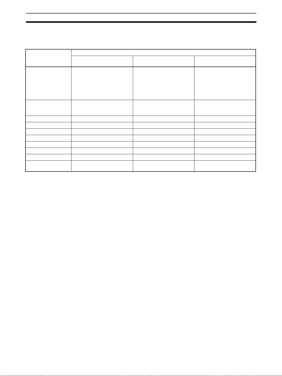
Outline Section 1-1
Note Relationship between CPU Unit I/O Memory and Loop Controller
The Loop Controller can read from and write to CPU Unit I/O memory by the
methods indicated in the following table.
Data direction Purpose of data on Loop Controller
Loop Controller
↔ CPU Unit
I/O memory area type
on CPU Unit
CIO ❍ Reading/writing of CIO area on
Work Area (W) ❍ --- ---
Holding Area (H) ❍ --- ---
Auxiliary Area --- --- --TR Area --- --- --Timer --- --- --Counter --- --- --Data Memory Area (D) ❍ --- ---
Extended Data Mem-
ory Area (E)
Reading or writing at CPU Unit
T erminals, Expanded CPU Unit
Terminals, or Send/Receive All
Blocks
❍ : Possible,
---: Impossible
❍ (bank No.0 only) --- ---
Loop Controller
↔ CPU Unit
Reading or writing at field terminals
corresponding Unit at field terminals
Loop Controller
→ CPU Unit
Writing using the Auxiliary
Area
Notifying of Loop Controller
status
1-1-12 Internal Mechanism of Loop Controllers
The following describes the internal mechanism of the Loop Controller.
• Function block dat a and error log data are bac ked up by a super capacitor
in RAM. During actual operation, the Loop Controller uses the data in
RAM.
• Function block data is prepared and downloaded to RAM and flash memory in the Loop Controller from CX-Process Tool running on the computer.
From the CX-Process Tool, you can transfer data between RAM and flash
memory whenever necessary.
• Error log data is stored in flash memory can be read using the READ
ERROR LOG FINS command (command code 2102 Hex).
• In the default state, function block data is not stored on the Loop Controller. Function block data must be downloaded from a computer to RAM
and flash memory in the Loop Controller before the Loop Controller can
be run.
23
Page 56

Outline Section 1-1
Function block data prepared and
downloaded to RAM from CX-Process Tool
The contents of RAM and flash
memory can be transferred back
and forth as required.
Super
capacitor
Backup
Loop Controller
Function block data sheet
Download
RAM
(all function block data)
Allocated data
Command
Back up
Recover
Cold start
Cold start Read/Write and Read-only ITEM data
Flash memory
Function block data
Including error log data
At each operation execution
Every 1 second
(For the CS1D-LCB05D,
each CPU Unit cycle)
CPU Unit
I/O memory
HMI
interface
(EM Area)
Auxiliary
Area
Note 1. Function block data in RAM can be back ed up to flash memory using either
of the following methods.
a. When downloading LCB01, LCB05, or LCB05D function block data
(i.e., by LCBs), specify LCB backup for the download (i.e., by placing
a check mark by “LCB back up indication after download”).
b. Specify backup from the CX-Process Tool software using the Execute
- Backup menu command.
2. Recovering data from flash memor y to RAM is also possible using either
of the following methods.
a. Set the power ON startup mode to Cold Start and turn ON the power
supply to the CPU Unit.
b. Specify recovery from the CX-Process Tool software using the Exe-
cute - Recovery me nu command.
3. Specify backup using ITEM 125 (Backup start command while running) of
the System Common Block (Block Model 000).
During operation of the Loop Controller, the backup will start when
ITEM 125 (Backup start command while running) of the System Common
Block (Block Model 000) is turned ON.
4. If duplex operation is used with the CS1D-CPU@@P and data in LCB Units
is downloaded during operation, operation data will be backed up in the
flash memory of only the active Board. The Loop Controller will stop operating at this time. If the power supply is turned OFF before starting operation with either a hot or cold start, the data will exist only in the flash
memory of the active Board, so a duplex verification error will occur. If this
occurs, check the RDY indicator on the standby Loop Con troller in the CPU
Unit to make sure that it is ready to oper ate and then press the initialization
switch on the Duplex Unit to initialize duplex operation.
24
Page 57

Outline Section 1-1
1-1-13 List of Function Blocks
Note (1) The Function Blocks dealing with high-speed operation (operation cycle:
0.01, 0.02, and 0.05 seconds is possible) Ho wever, Not supported by the
LCB05D.
(2) LCB01/05 Ver.1.5 or later only.
(3) LCB05/05D only.
(4) LCB01/05 Ver.2.0 or later and LCB03 only.
(5) CS-series only.
(6) CJ-series only.
(7) LCB01/03/05 Ver. 3.5 or later only.
Category Type Block
Model
System
000 System ComCommon
Block
Control
Block
Controller 001
(See note
1.)
002
(See note
1.)
011
(See note
1.)
012
(See note
1.)
013 Blended PID Performs PID control on the cumulative
014 Batch Flowrate
016 Fuzzy Logic Outputs up to two analog outputs based on
031
(See note
1.)
032
(See note
1.)
033
(See note
1.)
034
(See note
1.)
External
Controller
Block
External
Controller Block
045 ES100X Con-
Block Name Function Allocatable Block
Address
mon
2-position
ON/OFF
3-position
ON/OFF
Makes settings common to all function
blocks and outputs signals for the system.
2-position type ON/OFF controller LCB05/05D: 001 to 500
3-position type ON/OFF controller for heating/cooling ON/OFF control
000
LCB03: 001 to 300
LCB01: 001 to 050
Basic PID Performs basic PID control.
Advanced PID Performs PID with two degrees of freedom
control for enabling deviation/MV compensation, MV tracking, etc.
value (cumulative devia tion) between the
accumulated value PV and accumulated
value Remote Set Point.
Functions to open the valve at a fixed open-
Capture
ing until a fixed ba t ch accu m ul ate d value is
reached.
LCB05/05D: 001 to 100
Indication and
Setting
Indication and
Operation
fuzzy logic performed on up to 8 analog
inputs.
Manual setter with PV indication and SP
setting functions
Manual setter with PV indication and MV
setting functions
LCB03: 001 to 100
LCB01: 001 to 050
LCB05/05D: 001 to 500
LCB03: 001 to 300
LCB01: 001 to 050
Ratio Setting Ratio and bias setter with PV indication and
ratio setting function
Indicator PV indicator with PV alarm
troller Terminal
Performs monitoring and setting for an
ES100X Controller connected directly to
the RS-232C port on the Loop Control Unit.
LCB01/05: 601 to 632
LCB05D, LCB03: Not
supported.
25
Page 58

Outline Section 1-1
Category Type Block
Model
Operation
Block
Alarm/
Signal
restrictions/Hold
111
(See note
1.)
112
(See note
1.)
113
(See note
1.)
115
(See note
1.)
116
(See note
1.)
118
(See note
1.)
Arithmetic 121
(See note
1.)
122
(See note
1.)
123
(See note
1.)
126
(See note
1.)
127
(See note
1.)
Functions 131
(See note
1.)
132
(See note
1.)
133
(See note
1.)
134
(See note
1.)
135
(See note
1.)
136
(See note
1.)
Block Name Function Allocatable Block
Address
High/Low Alarm Provides the alarm contact outputs for the
high and low limits of single analog signals.
Deviation Alarm Provides the alarm contact outputs for the
LCB05/05D: 001 to 500
LCB03: 001 to 300
LCB01: 001 to 050
deviation of two analog signals.
Rate-of-change
Operation and
Alarm
Provides the alarm contact outputs for the
high and low limits of rate-of-change operation when the analog signal rate-of-change
is output.
High/Low Limit Li m its the high and low limits of single ana-
log signals.
Deviation Limit Calculates the deviation between two ana-
log signals, and limits the deviation within
that range.
Analog Signal
Hold
Addition or Subtraction
Holds the maximum, minimum or instantaneous value of single analog signals.
Perf orms addition/subtraction with gain and
bias on up to 4 analog signals.
Multiplication Performs multiplication with gain and bias
on up to 2 analog signals.
Division Performs division with gain and bias on up
to 2 analog signals.
Arithmetic Operation
Range Conversion
Square Root Performs square root extraction (with low-
Performs various math operation (trigonometric. logarithmic, etc.) on floating-point
decimal values converted (to industrial
units) from up to 8 analog inputs.
Easily converts up to 8 analog signals simply by inputting the 0% and 100% input values and 0% and 100% output values.
LCB05/05D: 001 to 100
LCB03: 001 to 300
LCB01: 001 to 050
LCB05/05D: 001 to 500
LCB03: 001 to 300
LCB01: 001 to 050
end cutout) on single analog signals.
Absolute Value Performs non-linear (3 gain values) opera-
tion on single analog signals. Analog signals can also set as a dead band (with
different gap).
Non-linear Gain
(Dead Band)
Outputs the absolute value of single analog
signals
Low-end Cutout Sets output to zero close to the zero point
of single analog signals.
Segment Linearizer
Temperature
And Pressure
Converts single analog signals to 15 segments before the signals is output.
Perf orms temperature and pressure correction.
Correction
26
Page 59

Outline Section 1-1
Category Type Block
Model
Operation
Block (continued)
Time
Function
141
(See note
1.)
143
(See note
1.)
145
(See note
1.)
147
(See note
1.)
148
(See note
1.)
149
(See note
1.)
150 Accumulator for
151 Run Time Accu-
153
(See note
1.)
155 Ramp Program Ramp program setter for combining ramps
156 Segment Pro-
157 Segment Pro-
158
(See note
7.)
601 Step Data Expansion settings for Segment Program 3
602 Bank Data Expansion settings for Segment Program 3
Block Name Function Allocatable Block
Address
First-order Lag Performs first-order lag operation on single
analog signals.
Rate-of-change
Limit
Perf orms rate-of-change restriction on single analog signals.
LCB05/05D: 001 to 500
LCB03: 001 to 300
LCB01: 001 to 050
Moving Aver age Performs moving average operation on sin-
gle analog signals.
Lead/Delay Performs lead/delay operation on single
analog signals.
Dead Time Performs dead time and first-order lag
operations on single analog signals.
Dead Time
Compensation
Used for Smith's dead time compensation
PID control
Accumulates analog signals, and outputs
instantaneous
8-digit accumulated value signals.
value input
Accumulates the operating time, and out-
mulator
Time Sequence
Data Statistics
puts the pulse signal per specified time.
Records time sequence data from analog
signals and calculates statistics, such as
averages and standard deviations.
LCB05/05D: 001 to 100
LCB03: 001 to 100
LCB01: 001 to 050
LCB05/05D: 001 to 500
gram
for time and hold values.
Segment program setter setting the output
values with respect to time.
LCB03: 001 to 300
LCB01: 001 to 050
Segment program setting with wait function
gram 2
for setting the output values with respect to
time
Segment Program 3
Segment program setting with wait function
and bank (e.g., PID) switching function for
setting output values with respect to time.
block (Block Model 158). Sets step data,
such as the time width and output value.
block (Block Model 158). Sets bank data,
such as the PID constants.
27
Page 60

Outline Section 1-1
Category Type Block
Model
Operation
Block (continued)
Signal
Selection/
Switching
161
(See note
1.)
162
(See note
1.)
163
(See note
1.)
164
(See note
1.)
165
(See note
1.)
166
(See note
1.)
167 Ramped Switch Switches two analog inputs (or constants)
168
(See note
2.)
169
(See note
2.)
ITEM Settings
Pulse
171
(See note
1.)
172
(See note
1.)
174
(See note
1.)
182 Accumulated
Train
Operation
183 Accumulated
184 Accumulator for
185 Contact
186 Accumulated
Block Name Function Allocatable Block
Address
Rank Selector Selects the rank of up to 8 analog signals. LCB05/05D: 001 to 500
LCB03: 001 to 300
Input Selector Selects the specified analog signals speci-
LCB01: 001 to 050
fied by the contact signal from up to 8 analog signals.
3-input Selector Selects and outputs one of three analog
input signals.
3-output Selector
Constant Selector
Constant Gen-
Outputs one analog input signal in three
switched direction.
Selects 8 preset constants by the contact
signal.
Outputs 8 independent constants.
erator
with a ramp.
Bank Selector Records the PID parameters (SP, P, I, D,
MH, ML) in up to 8 sets in advance, and
switches the PID parameter for
Basic/Advanced/Blended PID Blocks
according to the analog input range (zone)
or input bits.
Split Converter Inputs the MV from the Basic PID block or
Advanced PID block, converts the MV into
two analog outputs for V characteristics or
parallel characteristics (e.g., MV for heating
or cooling) and outputs them.
Constant ITEM
Setting
Variable ITEM
Setting
Writes the constant to the specified ITEM
at the rising edge of the send command
contact.
Writes the analog signal to the specified
ITEM at the rising edge of the send com-
LCB05/05D: 001 to 500
LCB03: 001 to 300
LCB01: 001 to 050
mand contact.
Batch Data Collector
Stores each of max. 8 analog inputs to
buffer by a certain timing within sequential
processing.
Adds up to four accumulated value signals.
Va l u e Input
Adder
Multiplies analog signals by the accumuValue Analog
lated value signals.
Multiplier
Converts 4-digit accumulated value signals
accumulated
to 8 digits.
value input
Counts low-speed contact pulses, and outinput/Accumu-
puts 8-digit accumulated signals.
lated value output
Converts 4-digit accumulated value signals
Value
Input/Contact
to low-speed contact pulses before they are
output.
Output
28
Page 61

Outline Section 1-1
Category Type Block
Model
Operation
Block (continued)
Others 192
(See note
1.)
Sequence
Operation
201
(See note
1.)
202
(See note
1.)
203
(See note
1.)
205
(See note
1.)
206
(See note
1.)
207
(See note
1.)
208
(See note
1.)
209
(See note
1.)
210
(See note
1.)
Contact
221 ON/OFF Valve
Type Control Target
222 Motor Manipula-
223 Reversible
224 Motor Opening
225 Switch Meter Manipulates and monitors multiple devices
Sequential
Control
301
(See note
1.)
302
(See note
3.)
Block Name Function Allocatable Block
Address
Analog/Pulse
Width Converter
Contact Distributor
Constant Comparator
Changes the ON/OFF duration ratio in a
constant cycle duration so that it is proportional to the analog signal.
Connect contact signals between function
blocks in a 1: 1 connection.
Compares up to eight sets of analog signals and constants, and outputs the com-
LCB05/05D: 001 to 500
LCB03: 001 to 300
LCB01: 001 to 050
parison results as contacts.
Variable Comparator
Compares up to eight pairs of analog signals, and outputs the comparison results as
contacts.
Timer 2-stage output type addition timer for fore-
cast values and reached values. Can also
output the present value.
ON/OFF Timer Timer for performing ON-OFF operation at
preset ON and OFF times.
Clock Pulse Manipulates and monitors ON/OFF valves
with open/close limit switches.
Counter 2-stage output type addition timer for fore-
cast values and arrival values. Can also
output the current value.
Internal Switch Temporary storage contact for accepting
relays in the Step Ladder Program block.
(Note: One internal switch is already allo-
cated as “temporary storage” in CX-Process Tool.)
Level Check Checks an analog input for 8 levels and
outputs a contact corresponding to the
level. The le v el number is also output as an
analog value.
Manipulator
tor
Manipulates and monitors ON/OFF valves
with open/close limit switches.
Manipulates and monitors motor operation.
LCB05/05D: 001 to 500
LCB03: 001 to 300
LCB01: 001 to 050
Manipulates and monitors reversible motor
Motor Manipula-
operation.
tor
Inputs a target opening, and manipulates
Manipulator
an electric positional-proportional motor.
(up to 8) such as ON/OFF valves, motors,
and pumps.
Step Ladder
Program
Sequence table Conditions and actions are listed in table
Perf orms logic sequence and step progression control.
LCB01: 701 to 720
LCB03/05/05D: 701 to
900
format to perform logic sequence or step
progression control.
Note: CS1W-LCB05/05D only; not supported by the CS1W-LC B 0 1.
29
Page 62

Outline Section 1-1
Category Type Block
Model
Field Termi nal
Contact
I/O
501
(See note
1.)
502
(See note
1.)
503
(See note
1.)
504
(See note
1.)
511
(See note
1.)
512
(See note
1.)
513
(See note
1.)
514
(See note
1.)
515
(See note
1.)
516
(See note
1.)
518
(See note
1.)
525
(See note
1.)
537
(See note
1.)
544
(See note
1.)
Analog
I/O
551
(See note
1.)
552
(See note
1.)
553
(See note
1.)
561
(See notes
1 and 5.)
562
(See notes
1 and 5.)
563
(See notes
1 and 5.)
Block Name Function Allocatable Block
Address
DI 8-point Ter-
Inputs 8 contacts from 8-point Input Unit. 901 to 980
minal
DI 16-point Ter-
Inputs 16 contacts from 16-point Input Unit.
minal
DI 32-point Ter-
Inputs 32 contacts from 32-point Input Unit.
minal
DI 64-point Ter-
Inputs 64 contacts from 64-point Input Unit.
minal
DO 5-point Ter-
minal
DO 8-point Ter-
minal
DO12-point Ter-
minal
DO16-point Ter-
minal
DO32-point Ter-
minal
DO64-point Ter-
minal
DI 16-
point/Do16-point
Outputs 5 contacts from 5-point Output
Unit.
Outputs 8 contacts from 8-point Output
Unit.
Outputs 12 contacts from 12-point Output
Unit.
Outputs 16 contacts from 16-point Output
Unit.
Outputs 32 contacts from 32-point Output
Unit.
Outputs 64 contacts from 64-point Output
Unit.
Inputs and outputs 16 contacts each from
16-point Input/16-point Output Units.
Terminal
DI 96-point Ter-
minal
DO 96-point Ter-
minal
DI 48-point/DO
48-point Termi-
Inputs 96 contacts from 96-contact Input
Units.
Outputs 96 contacts from 96-contact Output Units.
Inputs and outputs 48 contacts each from
48-point Input/48-point Output Units.
nal
AI 8-point Termi-
nal (AD003)
AO 8-point Ter-
minal (DA003/4)
AI 2-point/AO 2-
point Terminal
Inputs 8 analog signals from the C200HAD003.
Inputs 8 analog signals from the C200HDA003/DA003.
Inputs and outputs 2 analog signals each
from the C200H-MAD01.
901 to 980
(MAD01)
AI 4-point Termi-
nal
(PTS01/02/03,P
DC01, PTW01)
Inputs 4 analog signals from one of CS1WPTS01 (Isolated-type Thermocouple Input
Unit), CS1W-PTS02/03 (Isolated-type Temperature-resistance Thermometer Input
Unit), CS1W-PDC01 (Isolated-type Analog
Input Unit) or CS1W-PTW01 (2-lead Transmitter Input Unit).
PI 4-point Terminal (PPS01)
Inputs 4 instantaneous values and accumulated values each from CS1W-PPS01 (Isolated-type Pulse Input Unit).
AO 4-point Terminal (PMV01)
Outputs 4 analog signals from CS1WPMV01 (Isolated-type Control Output Unit).
30
Page 63

Outline Section 1-1
Category Type Block
Model
Field Termi nal
Analog
I/O
564
(See notes
1 and 5.)
565
(See notes
1 and 5.)
566
(See note
4.)
567
(See note
4.)
568
(See notes
4 and 5.)
569
(See notes
4 and 5.)
570
(See notes
4 and 5.)
571
(See note
7.)
572
(See notes
6 and 7.)
573
(See notes
6 and 7.)
581
(See notes
6 and 7.)
582
(See note
7.)
583
(See notes
1 and 5.)
584
(See note
1.)
585
(See note
1.)
586
(See note
1.)
587
(See note
1.)
588
(See note
1.)
589
(See note
1.)
591
(See notes
4 and 5.)
592
(See notes
4 and 5.)
Block Name Function Allocatable Block
Address
AI 8-point Terminal (PTR01/02)
Inputs 8 analog signals from CS1W-PTR01
(Power Transducer Input Unit) or CS1W-
901 to 980
PTR02 (Analog Input Unit (100 mV)).
AO 4-point Terminal (PMV02)
AI 4-point Terminal (PTS51)
Outputs 4 analog signals from CS1WPMV02 (Isolated-type Control Output Unit).
Inputs 4 analog signals from CS1W-PTS51
or CJ1W-PTS51
(Isolated-type Thermocouple Input Unit).
AI 4-point Terminal (PTS52)
Inputs 4 analog signals from CS1W-PTS52
or CJ1W-PTS52
(Isolated-type Thermocouple Input Unit).
AI 8-point Terminal (PTS55)
AI 8-point Terminal (PTS56)
AI 8-point Terminal (PDC55)
AI 2-point Terminal (PTS15/16,
Inputs 8 analog signals from CS1W-PTS55
(Isolated-type Thermocouple Input Unit).
Inputs 8 analog signals from CS1W-PTS56
(Isolated-type Thermocouple Input Unit).
Inputs 8 analog signals from CS1W-PDC55
(Direct current Input Unit).
Inputs 2 analog outputs from CS1WPTS15, CS1W-PT S16 , or CS1W-PDC15.
PDC15)
AI 4-point Termi-
nal (PH41U)
Inputs 4 analog signals from CJ1W-PH41U
(Isolated-type High-resolution Analog Input
Unit with Fully Universal Inputs)
AI 4-point Terminal (AD04U)
Inputs 4 analog signals from CJ1W-AD04U
Isolated-type General-purpose Input Unit
with Fully Universal Inputs)
AI 4-point Terminal (ADG41)
AI 16-point Terminal (AD161)
AI 4-point/AO 4point Terminal
Inputs 4 analog signals from CJ1W-ADG41
(High-speed Analog Input Unit)
Inputs 16 analog outputs from CS1WAD161.
Inputs and outputs 4 analog signals each
from the CS1W-MAD44.
(MAD44)
AI 8-point Termi-
nal (AD081)
AO 8-point Ter-
minal
Inputs 8 analog signals from the CS1WAD081(-V) or CJ1W-AD081(-V).
Outputs 8 analog signals from the CS1WDA08V/DA08C or CJ1W-DA08V/DA08C.
(DA08V/C)
AI 4-point Termi-
nal (AD041)
AO 4-point Ter-
minal (DA041)
AI 4-point Termi-
nal (DRT1-
Inputs 4 analog signals from the CS1WAD041(-V1) or CJ1W-AD041(-V1)
Outputs 4 analog signals from the CS1WDA041 or CJ1W-DA041.
Inputs four analog signals from a DRT1AD04 DeviceNet Slave Analog Input Unit.
AD04)
AO 2-point Ter-
minal (DRT1-
Outputs two analog signals from a DRT1DA02 DeviceNet Slave Analog Output Unit.
DA02)
AO 2-point Ter-
minal (DA021)
AI 4-point/AO 2-
point Terminal
Outputs 4 analog signals from the CJ1WDA021.
Inputs 4 analog signals and outputs 2 analog signals each from the CJ1W-MAD42.
(MAD42)
31
Page 64

Outline Section 1-1
1-1-14 Differences between Loop Control Units and Boards
Area Item Loop Control
Unit
Model number CS1W-LCU01 CS1W-LCB01/05 CS1D-LCB05D CJ1G-CPU@@P
Functional
components
Hardware Unit classification CPU Bus Unit Inner Board
CPU Unit component
Loop Controller
component
Compatible CPU
Units
Number of mountable Units/Boards
per CPU Backplane
Duplex mode Not supported Not supported Supported Not supported
Unit number set-
tings
RAM backup
method
LED Indicators RUN, ERC, ERH,
--- --- CS1D-CPU@@H CJ1G-CPU@@H
LC001 LCB01/05 LCB05D LCB01: CJ1W-
CS1, CS1-H, or
CS1D CPU Units
3 Units 1 Board Two CS1D Process-
0 to F None
Super capacitor
and battery
SD, and RD
Loop Control
Board
LCB01 Control and
Operation Blocks:
50 max.
LCB05 Control and
Operation Blocks:
500 max.
CS1-H CPU Units --- ---
Super capacitor Super capacitor
RDY, EXEC, and COMM
Process-control
CPU Unit
Process-control
CPU Unit (a CS1DCPU@@H and Loop
Control Board set)
500 Control and
Operation Blocks
max.
control CPU Units of
the same model
(each Unit includes
1 Board)
Loop-control CPU
Unit
CPU42P
LCB03: CJ1WCPU43/44/45P
CJ1 CPU Unit with
built-in Loop Control Board
---
(Super capacitor is
backed up by Battery in CPU Unit.)
32
Page 65

Outline Section 1-1
Area Item Loop Control
Main functions Operation cycle 100, 200, 500,
Execution speed 1 About 10 times
CPU Unit cycle
time restrictions
Speed of data
exchange with
CPU Unit
Max. delay before
hot start
Cold start The internal mem-
Automatic transf er
from flash memory
to RAM at Power
ON
Load rate Displayed each
Operation cycle
shift down
User Link Table
function
Memory areas
allocated to the
CPU Unit for
SCADA software
Contents of CSV
tag files
Sequence control/Step progression control
Unit
1,000, or 2,000 ms
None None Must be 1/5 the
1 cycle time +
operation cycle
Up to one year
after power is
turned OFF.
ory used for operations is cleared to
0.
Executed when
DIP switch pin 2 is
ON.
operation cycle.
The Unit automati-
cally shifts to a
longer operation
cycle when the
load rate exceeds
70%.
None (Expanded
CPU Unit Terminals are used.)
Send and receive
areas of all Blocks
Allocated Control
Block and Operation Block ITEMs
set in the CSV
tags.
Performed with the
Step Ladder Program.
Loop Control
Board
10, 20, 50, 100,
200, 500, 1,000, or
2,000 ms
faster than the Loop
Control Unit
Operation cycle Refreshing split
Up to 24 hours after power is turned OFF
(at an ambient temperature of 25°C).
The Board reads the function block data that was backed up to
flash memory and also reads the HMI data stored in the CPU
Unit's EM area. The internal memory used for operations is
cleared to 0.
Executed in a cold start.
Changes from the LCB load rate and displays the overall load
rate.
The Board does not shift to a longer operation cycle. If the load
rate exceeds 80% for six seconds consecutively, a non-fatal
Inner Board error will occur (operation will continue) and the
High Load Alarm Flag (A42408) will turn ON. If the operations
cannot be executed in the operation cycle, the operation cycle
will be extended and the operations will be executed.
Supported
HMI function (specified EM bank)
1) Allocated Control Block, Operation Block, and System Common Block ITEMs set in the CSV tags.
2) User Link Table tags
Perf ormed with either the sequence table or Step Ladder Program.
(Note: The CS1W-LCB01 supports step ladder programming
only.)
Process-control
CPU Unit
100, 200, 500,
1,000, or 2,000 ms
Note 1: 10, 20, and
50 ms are not supported.
Note 2: The operation cycle must be
set to a minimum of
5 times the CPU
Unit cycle time.
About 8 times faster
than the Loop Control Unit
shortest operation
cycle or less.
over multiple CPU
Unit cycles during
Board operation
cycle
Loop-control CPU
Unit
10, 20, 50, 100,
200, 500, 1,000, or
2,000 ms
About 10 times
faster than the Loop
Control Unit
None
Operation cycle
Up to 5 minutes
after power is
turned OFF (at an
ambient temperature of 25°C).
33
Page 66

Outline Section 1-1
Area Item Loop Control
Function
blocks
Max. number of
registered Blocks
Types of Function
Blocks
Control Blocks: 32
Operation Blocks:
249
Step Ladder Program
ES100X Controller
Terminal
DI Terminal from
CPU Unit
DO Terminal to
CPU Unit
AI Terminal from
CPU Unit
AO Termina l from
CPU Unit
Expanded DI Terminal from CPU
Unit
Expanded DO Terminal from CPU
Unit
Expanded AI Terminal from CPU
Unit
Expanded AO Terminal from CPU
Unit
Receive All Blocks HMI function
Send All Blocks
4-Point Warning
Indicator
Unit
Loop Control
Board
The total number of
Control Blocks and
Operation Blocks is
limited as follows:
LCB01: 50 Blocks
max.
LCB05: 500 Blocks
max.
The total number of
Fuzzy Logic Blocks
(Block Model 016),
Arithmetic Operation Blocks (Block
Model 126), and
Time Sequence
Data Statistics
Blocks (Block Model
153) is limited to
100 Blocks max.
Step Ladder Program or sequence table (cannot be used
together)
(Note: LCB01 and LCB03 support step ladder programming
only.)
ES100X Controller
Terminal
User link table
(HMI-related ITEM settings for System Common Block)
None (Combined with the Indicator Block (Block Model 034.))
Process-control
CPU Unit
The total number of
Control Blocks and
Operation Blocks is
limited to 500
Blocks max.
External Controller
Terminal Blocks
(Block Model 045)
are not supported.
The total number of
Fuzzy Logic Blocks
(Block Model 016),
Arithmetic Operation Blocks (Block
Model 126), and
Time Sequence
Data Statistics
Blocks (Block Model
153) is limited to
100 Blocks max.
Not supported
Loop-control CPU
Unit
The total number of
Control Blocks and
Operation Blocks is
limited as follows:
LCB01: 50 Blocks
max.
LCB03: 300 Blocks
max.
External Controller
Terminal Blocks
(ES100X Controller
Terminal (Block
Model 045)) are not
supported.
The total number of
Fuzzy Logic Blocks
(Block Model 016),
Arithmetic Operation Blocks (Block
Model 126), and
Time Sequence
Data Statistics
Blocks (Block Model
153) is limited to
100 Blocks max.
34
Page 67

Outline Section 1-1
Area Item Loop Control
Function
Blocks (continued)
Types of Function
Blocks (continued)
DO to Computer Function block for CX-Process Monitor so ftware
AO to Computer
1-Block Send Ter-
minal to Computer
4-Block Send Ter-
minal to Computer
DO Terminal to All
Nodes
AO Terminal to All
Nodes
DO Terminal Set-
tings from Computer
AO Termina l Settings from Computer
DI Terminal From
All Nodes
AI Terminal From
All Nodes
DI 8-point Terminal
DI 16-point Terminal
DI 32-point Terminal
DI 64-point Terminal
DO 5-point Terminal
DO 8-point Terminal
DO 12-point Terminal
DO 16-point Terminal
DO 32-point Terminal
DO 64-point Terminal
DI 16-point/DO
16-point Ter m inal
DI 96-point Terminal
DO 96-point Terminal
DI 48-point/DO
48-point Ter m inal
Unit
Loop Control
Board
The CX-Process Monitor software cannot be used for the Loop
Control Boards, Process-control CPU Units, or Loop-control
CPU Units.
The CX-Process Monitor Plus can be used for the Loop Control
Board.
User link table
Process-control
CPU Unit
Loop-control CPU
Unit
35
Page 68

Outline Section 1-1
Area Item Loop Control
Status Operating status
of Unit or Board
OR output of all
Function Block
alarms
Other None Inner Board Flags in Auxiliary Area words A401, A402, and
Command
Bits
START Mode at
Power ON
Unit
1) ITEMs in System Common
Block
2) Flags in the
allocated CPU
Bus Unit area
(word n)
None Flags in Auxiliary Area word A356
None Auxiliary Area word
1) ITEMs in System Common Block
2) Flags in Auxiliary Area word A355
A424
A609
1-1-15 Version Upgrade Information
The following functions have been added to the CS1W-LCB01 and CS1WLCB05 Loop Control Boards with the upgrade from Ver. 3.5 to Ver. 3.6.
• Select the appropriate unit version when registering an LCB/LC001 in CX
Process Tool (select Insert - Insert Node from the Settings Menu). If the
setting is incorrectly set to V1.0, V1.5, or V2.0, select Convert LCB
Model from the Execute Menu, and increase the unit version of the
LCU/LCB o the later version.
Loop Control
Board
Process-control
CPU Unit
Not supported.
Loop-control CPU
Unit
Item Ver. 1.0 Ver. 1.5 Ver. 2 .0 Ver. 3.0 Ver. 3.5 Ver. 3.6
Compatible CX-Process Tool version Ver. 3.2 or
lower
PV Lag Offset Correction
PV lag offset correction improves
tracking set values during program
control, using Basic PID blocks (Bloc k
Model 011) or Advanced PID blocks
(Block Model 012).
Segment Program 3 block (Block
Model 158) added.
Data backup during Loop Controller
operation added.
Simple backup file recovery using
FINS command added.
Improved Segment Program 2 block
(Block Model 157) functionality
Online editing of sequence tables Not sup-
Displaying PVs and changing SPs for
timers and counters in sequence
tables
Bank Selector block (Block Model
168) for PID constants
Split Converter block (Block Model
169)
Disturbance overshooting suppres-
sion for Basic PID (Block Model 011)
and Advanced PID (Block Model 012)
Not supported
Not supported
Not supported
Not supported
Not supported
ported
Not sup-
ported
Not supported
Not supported
Not supported
Ver. 3.2 or
higher
Not supported
Not supported
Not supported
Not supported
Not supported
Supported Supported Supported Supported Supported
Supported Supported Supported Supported Supported
Supported Supported Supported Supported Supported
Supported Supported Supported Supported Supported
Supported Supported Supported Supported Supported
Ver. 4.0 or
higher
Not supported
Not supported
Not supported
Not supported
Not supported
Ver. 5.0 or
higher
Not supported
Not supported
Not supported
Not supported
Not supported
Ver. 5.2 or
higher
Not supported
Supported Supported
Supported Supported
Supported Supported
Supported Supported
Ver. 5.2 or
higher (See
note.)
Supported
36
Page 69

Outline Section 1-1
Item Ver. 1.0 Ver. 1.5 Ver. 2 .0 Ver. 3.0 Ver. 3.5 Ver. 3.6
MV LImit Alarm Stop switch and MV
Alarm Control Stop switch for general
Control blocks
Easy backup of function block data
from Loop Controller to Memory Card
Memory Card backup for tag settings,
comments, and user link table connection information prepared using
CX-Process Tool
First or second reference input match
selection for Segment Program 2
(Block Model 157) start
Synchronization of Segment Program
2 (Block Model 157)
Hot start enabled time setting Not sup-
Secondary loop anti-reset wind-up
with cascade control
Added Split Converter block (Block
Model 169) input range setting from
0.00 to 100.00%
Added field terminal blocks --- --- AI 4-point
Other added function blocks Not sup-
Wireless debugging function
(Allows the user to enter pseudoinputs to a function block's PVs from
the CX-Process Tool or HMI I/F.)
MV tight shut function
(An analog output terminal can be a
tight shut output to the CPU Unit's I/O
memory from a user link table.)
MV analog output reversing function
(A field terminal (analog output terminal) can be inverted to the CPU Unit's
I/O memory from a user link table.)
RUN/STOP function
(Can ex ecute a RUN or STOP command for only one PID function, either
the Basic PID (Block Model 011) or
Advanced PID (Block Model 012)).
Not supported
Not supported
Not supported
Not supported
Not supported
ported
Not sup-
ported
Not sup-
ported
ported
Not supported
Not supported
Not supported
Not supported
Supported Supported Supported Supported Supported
Not supported
Not supported
Not supported
Not supported
Not supported
Not supported
Not supported
Not supported
Not supported
Not supported
Not supported
Not supported
Supported Supported Supported Supported
Supported Supported Supported Supported
Supported Supported Supported Supported
Supported Supported Supported Supported
Supported Supported Supported Supported
Supported Supported Supported Supported
Supported Supported Supported Supported
--Terminal
(PTS51/52)
AI 8-point
Terminal
(PTS55/56)
AI 4-point
Terminal
(PDC55)
AO 2-point
Terminal
(DA021)
AI 4point/AO 2point Terminal
(MAD42)
Not supported
Not supported
Not supported
Not supported
Not supported
AI 2-point
Terminal
(PTS15/16,
PDC15)
AI 16-point
Terminal
(AD161
Switch
Instrument
block (Block
Model 225)
Supported Supported Supported
Supported Supported Supported
Supported Supported Supported
Supported Supported Supported
In addition
to the ones
shown to
the left, the
following
field terminal blocks
were
added: AI 4point Terminal
(PH41U)AI
4-point Terminal
(AD04U)AI
4-point Terminal
(ADG41)
--- ---
37
Page 70

Configuration of Instrumentation System Section 1-2
Item Ver. 1.0 Ver. 1.5 Ver. 2.0 Ver. 3.0 Ver. 3.5 Ver. 3.6
Switch control action direction function
(Can switch the control action direction when operating the Basic PID
block (Block Model 011) or Advanced
PID (Block Model 012) in Auto mode.)
Reference sequence table function
(Can reference another table's condition judgment in the Sequence Table
block (Block Model 302).)
Added timer function
(Can specify a TIM (timer) command
in the Step Ladder block (Block Model
301).)
Pulse output function
(Can generate a pulse output (ON for
1 refresh cycle) in the user link tabl e.)
Expanded user link table EM specification
(EM banks other than EM bank 0
(EM0) can be specified as data areas
in the user link table.)
Number of constants that can be set
for the Constant ITEM Setting (Block
Model 171) increased from 8 maximum to 16 m aximum.
Including block diagram information,
tags, comments, and annotation data
in easy backup data along with function block data
Changing the data that is backed up
for easy backup function from RAM
data to flash memory data
Not supported
Not supported
Not supported
Not supported
Not supported
Not supported
Not supported
Not supported
Not supported
Not supported
Not supported
Not supported
Not supported
Not supported
Not supported
Not supported
Not supported
Not supported
Not supported
Not supported
Not supported
Not supported
Not supported
Not supported
Supported Supported Supported
Supported Supported Supported
Supported Supported Supported
Supported Supported Supported
Supported
banks EM1
to EMC can
be specified.
Supported Supported Supported
Supported Supported Supported
Supported Supported Supported
Supported
banks EM1
to EMC can
be specified.
Supported
banks EM1
to EMC can
be specified.
Note When using function component version 3.6 for LCB01, LCB03, or LCB05,
use the CX-One Auto Update function to upda te the CX-Process Tool Software to version 5.23 or higher.
1-2 Configuration of Instrumentation System
1-2-1 Mounting Location
Loop Control Boards
CS1W-LCB01 Loop
Control Board
The CS1W-LCB01 Loop Control Board is a non-duplex Inner Board for the
CS-series PLCs. It can be mounted in a CS1-H CPU Unit. It is not suppor ted
by and cannot be mounted in a CS1 CPU Unit.
CS1-H CPU Unit
CPU Rack
Mount in the Inner Board slot.
38
Page 71

Configuration of Instrumentation System Section 1-2
Mountable CPU Unit Models
Loop Control Board Inner Board type PLC Series CPU Unit model
CS1W-LCB01 Non-duplex stan-
dard
CS CS1H-CPU @@H
CS1G-CPU@@H
CS1W-LCB05 Loop
Control Board
Process-control CPU
Units
The CS1W-LCB05 Loop Control Board is a non-duplex Inner Board for the
CS-series PLCs. It can be mounted in a CS1-H CPU Unit. It is not supported
by and cannot be mounted in a CS1 CPU Unit.
Mountable CPU Unit Models
Loop Control Board Inner Board type PLC Series CPU Unit model
CS1W-LCB05 Non-duplex spe-
cial
CS CS1H-CPU @@H
CS1G-CPU@@H
The functions of Duplex Loop Control Board are built into the Inner Board of
the Process-control CPU Unit (CS1D-CPU@@P), so there is no need to
mount a separate Loop Control Board.
An Inner Board that is removed from one Unit cannot be mounted in any other
CS1D CPU Unit. Normal operation may not be possible if the Board is
installed in another CPU Unit.
DPL Unit
Duplex Loop Control Boards are mounted in the Inner
Board slots of the CS1D Process-control CPU Units.
Do not remove these Boards.
CS1D Process-control CPU Units (must be the same model)
CPU Rack
Loop-control CPU
Units
The Loop Control Board mounted in the active CPU Unit is active, and the Loop
Control Board mounted in the standby CPU Unit is the standby.
CPU Units
For duple x ope ration, always use two CS1D Process-control CPU Units of the
same model mounted to a CPU Duplex Backplane.
CS1D Process-control
CPU Units
CS1D-CPU65P Set consisting of the CS1D-CPU65H and the CS1D-
LCB05D. Write ladder programs for the CS1DCPU65H.
CS1D-CPU67P Set consisting of the CS1D-CPU67H and the CS1D-
LCB05D. Write ladder programs for the CS1DCPU67P.
Description
A Loop Control Board is built into the Loop-control CPU Unit (CJ1GCPU@@P), so there is no need to mount a Board.
39
Page 72

Configuration of Instrumentation System Section 1-2
CPU Units
Loop-control CPU Units Description
CJ1G-CPU42P CPU Unit with built-in Loop Control Board. Write lad-
der programs for the CJ1G-CPU42H.
CJ1G-CPU43/44/45P CPU Unit with built-in Loop Control Board. Write lad-
der programs for the CJ1G-CPU43H/44H/45H.
1-2-2 Determining the System Configuration
Check the following points when determining the system configuration:
1,2,3... 1. Number of Analog I/O Points Used on Loop Controller
Which analog signals are input/output on the AI/AO ter minals of the Field
Terminal block, and which analog signals are input/output on th e CPU Unit
Terminal block or the Expanded CPU Unit Terminal block?
The total number of usable AI/AO terminals on the Field Ter minal block
combined with the DO/DI terminals is 80. (For details of the Unit types that
can be used, see 1-2-3 Description of Basic System Configuration.)
The maximum number of usable CPU Unit Terminal blocks is 16. (For details of I/O memory area that can be specified, see 3-3-3 Exchanging Da-
ta.)
2. Number of Contact I/O Points Used on Loop Controller
Which contact signals are input/output on th e DI/DO t erminals of the Fiel d
T e rminal block, and which contact signa ls are input/output on the CPU Unit
Terminal block or the Expanded CPU Unit Terminal block?
The total number of DI/DO terminals on the Field Terminal block combine d
with the AO/AI terminals is 80 for the LCB01/05, 30 for the CJ1GCPU42/43P, and 40 for the CJ1G-CPU44/45P. (For details of the Unit types
that can be used, see 1-2-3 Description of Basic System Configuration.)
The maximum number of usable CPU Unit Ter minal blocks is 2,400. (For
details of I/O memory area that can be specified, see 3-3-3 Exchanging
Data.)
40
3. Current Consumption
Is the current consumption of the Units mounted on the rack less than the
current consumption of the Power Supply Unit?
Refer to CS1-series Operation Manual (Cat. No. W339), 2-6 Unit Current
Consumption.
4. Evaluation of Load Rate
The Loop Controller cyclically processes operation of its own function
blocks asynchronously with I/O refreshing of the CPU Unit. The cycle by
which operations are processed, or th e “operation cycle,” is dependent on
the type and number of function blocks used.
For this reason, when many function blocks whose operation takes a long
time to process are used, the actual operation cycle of the entire Loop
Controller or an individual function block increases. As a result, the desired
preset operation cycle sometimes cannot be satisfied.
The ratio between the actual execution time required for processing operation and the preset operation cycle is called the “load r ate.” The maximum
values and current value of each operation cycle group can be confirmed
on CX-Process Tool.
A load rate of 80% or less is required in all operation cycle groups on this
Loop Controller.
Page 73

Configuration of Instrumentation System Section 1-2
Note The High Load Alarm Flag (A42408) turns ON if the load rate exceeds 80%
for 6 seconds. If this happens, select the function blocks that can have longer
operation cycles and increase their operation cycles. If the load rate is still too
high, add on a CPU Unit or a CPU Unit and a Loop Control Unit and dist rib ut e
function block processing between the mounted Units.
5. CPU Unit Cycle Time and Minim um Operation Cycle (Pr ocess-control
CPU Unit Only)
When the Process-control CPU Unit (CS1D-CPU@@P) is used, the CPU
Unit cycle time must be considered in relation to the minimum operation
cycle in relation to the load rates outlined above.
a. Effect on CPU Unit Cycle Time
Effect on Normal CPU Unit Cycle Time
The following tab le shows the e xtra tim e added to the normal CPU Unit
cycle time when a Loop Controller is mounted.
Functional
component
Loop Control Board
(CS1W-LCB01/05)
Loop Controller component in the Process-control CPU
Unit (LCB05D)
Extra time added to normal cycle time
0.8 ms (depending on the function block data contents)
25 ms max. (depending on the function block data
contents)
Example of the Influence of the Process-control CPU Unit’s Loop
Controller on Normal Cycle Time
Function block and user link table operation cycle (See note (a).)
Number of function blocks 100 150 200
Number of user link tables 100 150 200
Load rate 39 55 71
Influence (ms) by 2-ms cycle time of ladder
program (See note (b).)
Influence (ms) by19-ms cycle time of lad-
der program (See note (b).)
100 ms
+7.8 +10.5 +13.6
+10.3 +14.4 +20.8
Note (a) The influence of the function block and user link table operation
cycle on the CPU Unit’s cycle time is greatest when the function
block and user link table operation cycle is 100 ms.
(b) The influence of the CS1D-LCB05D on the CPU Unit’s cycle time
is greatest when the cycle time of the CPU Unit is 19 ms.
(c) When sequence tables are used, the e xtra time in the ab ove table
is further extended. The additional extra time required depends
on how the sequence tables are used, as follows:
• Not expanding seque nce tables: +3 ms
• Expanding sequence tables vertically or horizontally: +6 ms
• Expanding sequence tables both vertically and horizontally:
+12 ms
The extended cycle time will not be lengthened if the number of e xpanded sequence tables increases, but the number of times that
the cycle time is extended will increase.
41
Page 74

Configuration of Instrumentation System Section 1-2
b. Restrictions on Minimum Operation Cycle for Loop Co ntroller In-
ternal Function Blocks
The operation cycle must be a minimum of 5 times the CPU Unit
cycle time.
When the Process-control CPU Unit (CS1D-CPU@@P) is used, it is
desirable to set the longest possible operation cycle to prevent errors
in the operation cycle. However, the operation cycle for the internal
function blocks of the Loop Controller component in the Process-control CPU Unit must be set to a minimum of 5 times the CPU Unit's normal cycle time. The normal cycle time is the cycle time other than
during duplex initialization.
Example: If the CPU Unit cycle time is 40 ms, the minimum operation
cycle for the function b loc ks in the Loop Controller componen t must be
at least 200 ms (i.e., 200 ms, 500 ms, 1 s, or 2 s.)
If the CPU Unit's normal cycle time is longer than 1/5 the minimum operation cycle for the internal function blocks of the Loop Controller
component in the Process-control CPU Unit, th e error in the oper atio n
cycle will increase. The error can be an increase of up to one CPU Unit
cycle time.
Note If the CPU Unit's normal cycle time is longer than 30% of the mini-
mum operation cycle for the Loop Controller’s internal function
blocks for 3 cons ecutive cycles, Auxiliary Area bit A42409 (Operation Cycle Error) will turn ON. Monitor this flag from the CX-Process
Tool system operation verification screen and if it turns ON, then
set the Loop Controller’s operation cycle to a minimum of 5 times
the CPU Unit's normal cycle time.
c. Effect on the Cyc le Time of th e CPU Unit and the O peration Cyc l e
of the Process-contro l CPU Unit ’s Loop Controller during Duplex
Initialization
With the Process-control CPU Unit, a maximum of 152 seconds is required for duplex initialization. The CS1D CPU Units and the active
Loop Control Board will operate during duplex initialization. The CPU
Unit’s cycle time and the Loop Controller’s operation cycle, however,
will be temporarily longer than normal. This increase in the cycle time
and operation cycle will be the largest during the last cycle time during
which duplex initialization is being performed. The increase will be the
same for both the cycle time and the operation cycle.
Design the overall system so that no system errors will occur during an
extended cycle time and operation cycle. Refer to 3-5 Duplex Opera-
tion of Loop Controllers for details on duplex initialization.
d. Details of Extended CPU Unit Cycle Time and Extended Opera-
tion Cycle
• Duplex Initialization (Only in Duplex Mode)
42
!Caution When using the Process-control CPU Unit (CS1D-CPU@@P), both the CPU
Unit cycle time and the Loop Controller component operation cycle will be
temporarily longer than normal during Duplex Initialization (in Duplex Mode).
There will be a temporary extension to the cycle time and operation cycle of a
maximum of 2.1 s at a maximum of approximately 150 s after the start of
duplex initialization. The extended cycle time and operation cycle may temporarily worsen the control characteristics, so verify the system's operation in
trial operation before actually running the system.
Page 75

Configuration of Instrumentation System Section 1-2
• For Cycles Other Than the Last CPU Unit Cycle (150 s max. during
Duplex Initialization)
Situation Extra CPU Unit Cycle Time
Operation on
CPU Unit component
Operation on
Loop Controller
component
• Power ON to PLC.
• When the Duplex Unit's
initialize switch is
turned ON.
Cold start command to
Loop Controller component
Inner Board restart when
A60800 turns ON.
When Loop Controller
component's internal
error history is cleared.
• For the Last CPU Unit Cycle during Duplex Initialization
Situation Extra CPU Unit Cycle Time
Operation on
CPU Unit
Operation on
Loop Controller
component
• Power ON to PLC.
• When the Duplex
Unit's initialize switch is
turned ON.
• When CPU Unit operation started.
• When data transferred
to CPU Unit (user programs, PLC Setup, I/O
tables, CPU Bus Unit
system settings area
transfers, online editing,
and timer/counter setting changes)
Cold start command to
Loop Controller component
Inner Board restart when
A60800 turns ON.
When Loop Controller
component's internal
error history is cleared.
and Duplex CS1D-LCB05D
Operation Cycle Time
44 ms max. (For both CS1DCPU65H and CS1DCPU67H)
and Duplex CS1D-LCB05D
Operation Cycle Time
CS1D-CPU65H: 1.83 s max.
CS1D-CPU67H: 2.13 s max.
The extra time depends on
the contents of the LCB05D
function block data, as shown
in the following examples.
Example 1: For 40 function
blocks, 5 sequence tables,
and 30 user link tables:
CS1D-CPU65H: 0.40 s max.
CS1D-CPU67H: 0.73 s max.
Example 2: For 200 function
blocks, 50 sequence tables,
and 600 user link tables:
CS1D-CPU65H: 1.26 s max.
CS1D-CPU67H: 1.59 s max.
Example 3: For 500 function
blocks, 200 sequence tables,
and 2,400 user link tables:
CS1D-CPU65H: 1.83 s max.
CS1D-CPU67H: 2.13 s max.
43
Page 76

Configuration of Instrumentation System Section 1-2
pp
Duplex Initialization Start
(Power to PLC turned ON, cold or hot start command executed, initialize
switch turned ON, Inner Board restarted, or error log cleared.)
Duplex Initialization Time (152 s max.)
(See note.)
CS1D CPU Unit
Operation
start
CS1D-CPU@@P
Process-control CPU Unit
Active side
Operation
start
Standby side
Operation
standby
a) Cycles Other Than the Last CPU Unit Cycle
150 s max.
CPU Unit’s cycle time
Extension of 44 ms max.
Loop Controller component’s operation cycle
Extension of 44-ms max.
Standby
Note: Duplex initialization at the start of CPU Unit operation or when data is transferred to the CPU Unit
will consist of b) only; a) will not be included.
a) Cycles other than the last CPU Unit cycle
b) Last CPU Unit cycle
b) Last CPU Unit Cycle
Approx. 2.1 s max.
Extension of
approx. 2 s max.
Extension of
approx. 2 s max.
Operation start
:
Extension of 44 ms max.
:
Extension of a
CPU Unit’s cycle time
Loop Controller component’s
operation cycle
Loop Controller component’s
operation cycle
rox. 2 s max.
Note The time required for duplex initialization depends on the type of operation
being performed, as shown in the following table.
Operation Duplex initialization time
Operations for
CPU Unit
Turning ON power to PLC a) 150 s max. + b) 2.1 s max.
Pressing initialization switch on
Duplex Unit
Starting CPU Unit operation Only b) 2.1 s max.
Transferring data to CPU Unit
Operations for
Loop Controller
component
Sending a cold or hot start command to the Loop Controller
Restarting the Loop Controller
a) 150 s max. + b) 2.1 s max.
component as an Inner Board
Clearing the error log in the
Loop Controller
6. Evaluation of External I/O Response Cyc le (Dependent on CPU Unit's
Cycle Time)
The operating speed (operation cycle) itself of each function block on the
Loop Controller is not related to the CPU Unit's cycle time. Howe ver , as the
CPU Unit's I/O memory is accessed during data exchange, for example,
between Analog I/O Units and the Basic I/O Unit, the timing of data exchange is greatly influenced by the CPU Unit's cycle time.
The external analog I/O response cycle (equ ivalent to the I/ O response cycle on a general controller) when the Loop Cont roller is conf igured a s part
44
Page 77

Configuration of Instrumentation System Section 1-2
of an instrumentation system is not the same as th e oper at ion cycle of the
function blocks; but is a cycle heavily dependent on the CPU Unit's cycle
time.
In most cases, the maximum external analog I/O response cycle is as follows depending on the operation timing:
“approximately 2 times the CPU Unit's cycle time” + “approximately twice
the operation cycles of the Loop Controller's function blocks”
So, when determining the system con figuration, ca lculate ho w long the e xternal analog I/O response cycle will be within the instrumentation system
based upon factors such as the CPU Unit's cycle time and the operation
cycles of the Loop Controller's funct ion bloc ks. Also , assess whether or not
there will be any prob lems when running applica tions at t he analo g I/O response cycle that you have calculated.
(For details on the rela tionship between the Loop Co ntroller's operation cycles and the CPU Unit's cycle time, see 3-2 Description of Operations. For
details on how to calculate the CPU Unit's cycle time , refer to the CS1-se-
ries Operation Manual (Cat. No. W339), 15-4 Computing the Cycle Time.)
7. Evaluation of Using Battery- free O perati on for CPU Unit or CPU Unit
Element
Battery-free operation cannot be used f or the CS1-H CPU Unit or the CPU
Unit element of a Process-control CPU Unit or Loop-control CPU Unit.
!WARNING Do not use battery-fr ee operation for the CS1-H CPU Unit or the CPU Unit
element of a Process-control CPU Unit or Loop-control CPU Unit. If batteryfree operation is used for the CPU Unit or CPU Unit element, the contents of
the EM Area will not be stable when the power supply is turned ON, possibly
causing illegal values in the HMI data in the Loop Controller.
1-2-3 Description of Basic System Configuration
Mounting of Units for
External Analog I/O
and Contact I/O
Note CS Series: CPU Rack, Expansion Rack, Expansion I/O Rack for the C200H,
The Loop Controller does not have direct external analog I/O and contact I/O
functions. External I/O is achieved via Analog I/O Units and Basic I/O Units
mounted on a basic PLC System (see note). (It is also possible to handle I/O
with external devices through DeviceNet Analog Slaves.)
or SYSMAC BUS Remote I/O Slave Rack
CJ Series: CPU Rack or Expansion Rack
So, in the basic system configuration, Analog I/O Units (Analog Input Unit,
Analog Output Unit, and Analog I/O Un it) must be mounted for the same PLC.
(It is also possible to input and output data for Analog I/O Units on other
nodes in a Controller Link or other network.)
A Basic I/O Unit must also be mounted for the same PLC as necessary.
Analog Output Unit
Analog Input Unit
Loop Control Board
CPU Unit
45
Page 78

Configuration of Instrumentation System Section 1-2
Input and Output of
Analog Data
The table below shows the Units with which the Loop Controller can e xchange
data without using user link tables. In data exchange with these Units, use the
AI Terminal or AO Terminal blocks on the Field Terminal block that corresponds to the required Unit model as the Loop Controller's function blocks.
On the AI Terminal and AO Terminal blocks, set the unit number of the Analog
I/O Unit to enable input/output of analog signals.
46
Page 79

Configuration of Instrumentation System Section 1-2
CS Series
Unit
information
CS-series Special I/O Unit
Name Specification Model Function block
Analog Input/Output Unit
Analog Input Unit 4 inputs (1 to 5 V, 4 to 20 mA, etc.) CS1S-AD041 AI 4-point Terminal
Analog Output Unit 4 outputs (1 to 5 V/4 to 20 mA, etc.) CS1W-DA041 AO 4-point Terminal
Isolated-type Thermocouple Input
Unit
Isolated-type Temperature-resistance Thermometer
Input Unit
Isolated-type 2-lead
Transmitter Input
Unit
Isolated-type Analog Input Unit
4 inputs (1 to 5 V, 4 to 20 mA, etc.)
4 outputs (1 to 5 V, 0 to 10 V, etc.)
8 inputs (1 to 5 V, 4 to 20 mA, etc.) CS1S-AD081 AI 8-point Terminal
16 inputs (1 to 5 V, 4 to 20 mA, etc.) CS1W-AD161 AI 16-point Terminal
8 outputs (1 to 5 V, etc.) CS1W-DA08V AO 8-point Terminal
8 outputs (4 to 20 mA) CS1W-DA08C AO 8-point Terminal
4 inputs (B, E, J, K, N, R, S, T,
DC±80 mV)
4 inputs (B, E, J, K, L, N, R, S, T, U,
WRe5-26, PLII, mV)
4 inputs (K, J, L, R, S, T, B) CS1W-PTS51 Ai 4-point Terminal
8 inputs (K, J, L, R, S, T, B) CS1W-PTS55 Ai 8-point Terminal
4 inputs (Pt100, JPt) CS1W-PTS02 AI 4-poin t Terminal
4 inputs (Ni508.4Ω) CS1W-PTS03 AI 4-point Terminal
4 inputs (Pt100, JPt100, Pt50,
Ni508.4Ω)
4 inputs (Pt100, JPt100) CS1W-PTS52 Ai 4-point Terminal
8 inputs (Pt100, JPt100) CS1W-PTS56 AI 8-point Terminal
4 inputs (1 to 5 V, 4 to 20 mA), builtin power supply for 2-lead Transmitter
4 inputs (1 to 5 V, 4 to 20 mA, etc.) CS1W-PDC01 AI 4-point Terminal
4 inputs (1 to 5 V, 4 to 20 mA, etc.) CS1W-PDC11 Not supported
CS1W-MAD44 AI 4-point/AO 4-point
Terminal (Block
Model 583)
(Block Model 586)
(Block Model 584)
(Block Model 582)
(Block Model 587)
(Block Model 585)
(Block Model 585)
CS1W-PTS01-V1 AI 4-point Terminal
(Block Model 561)
CS1W-PTS11 Not supported
(Block Model 566)
(Block Model 568)
(Block Model 561)
(Block Model 561)
CS1W-PTS12 Not supported
(Block Model 567)
(Block Model 569)
CS1W-PTW01 AI 4-point Terminal
(Block Model 561)
(Block Model 561)
Isolated-type Analog Output Unit
(Analog Output
Unit)
Power Transducer
Input Unit
Analog Input Unit
(100 mV)
Isolated-type Pulse
Input Unit
8 inputs (1 to 5 V, 4 to 20 mA, etc.) CS1W-PDC55 AI 8-point Terminal
4 outputs (1 to 5 V, 4 to 20 mA) CS1W-PMV01 AO 4-point Terminal
4 outputs (−10 to 10 V, 0 to 10 V, −5
to 5 V, 1 to 5 V, −1 to 1 V, 0 to 1 V)
8 inputs (−1 to 1 mA, 0 to 1 mA) CS1W-PTR01 AI 8-point Terminal
8 inputs (−100 to 100 mA,
0 to 100 mA)
4 pulse inputs (0 to 20 Kpulses/s,
0 to 20 pulses/s)
CS1W-PMV02 AO 4-point Terminal
CS1W-PTR02 AI 8-point Terminal
CS1W-PPS01 PI 4-point Terminal
(Block Model 570)
(Block Model 563)
(Block Model 565)
(Block Model 564)
(Block Model 564)
(Block Model 562)
47
Page 80

Configuration of Instrumentation System Section 1-2
Unit
information
C200H Special
I/O Unit
Name Specification Model Function block
Analog Input Unit 8 inputs (select from 1 to 5 V, 4 to 20
mA, 0 to 10 V, or −10 to 10 V), Resolution: 1/4000
Analog Output Unit 8 outputs (select from 1 to 5 V, 0 to
Analog Input/Output Unit
10 V, or −10 to 10 V), Resolution:
1/4000
8 outputs (4 to 20 mA), Resolution:
1/4000
2 inputs (1 to 5 V, 4 to 20 mA, etc.)
2 outputs (1 to 5 V, 4 to 20 mA, etc.)
C200H-AD003 AI 8-point Terminal
(Block Model 551)
C200H-DA003 AO 8-point Terminal
(Block Model 552)
C200H-DA004 AO 8-point Terminal
(Block Model 552)
C200H-MAD01 AI 2-point/AO 2-point
Terminal (Block
Model 553)
Note In the case of an analog output Field Terminal block, select the function block
according to the Unit model.
CJ Series
Name Specification Model Function block
Analog Input/Output Unit 4 inputs (1 to 5 V, 4 to 20 mA, etc.)
2 outputs (1 to 5 V, 0 to 10 mA, etc.)
Analog Input Unit 4 inputs (1 to 5 V, 4 to 20 mA, etc.) CJ1W-AD041-V1 AI 4-point Terminal
4 inputs (1 to 5 V, 4 to 20 mA, etc.) CJ1W-AD081-V1 AI 8-point Terminal
4 inputs (high-speed model)
(1 to 5 V, 4 to 20 mA, etc.)
Analog Output Unit 4 outputs (1 to 5 V/4 to 20 mA, etc.) CJ1W-DA041 AO 4-point Terminal
8 outputs (1 to 5 V, etc.) CJ1W-DA08V AO 8-point Terminal
8 outputs (4 to 20 mA) CJ1W-DA08C AO 8-point Terminal
2 outputs (1 to 5 V/4 to 20 mA, etc.) CJ1W-DA021 AO 2-point Terminal
Isolated-type Thermocouple
Input Unit
Isolated-type Temperatureresistance Thermometer Input
Unit
Isolated-type High-resolution
Input Unit with Fully Universal
Inputs
Isolated-type General-purpose Input Unit with Fully Universal Inputs
4 inputs (B, E, J, K, L, N, R, S, T, U,
WRe5-26, PLII, mV)
2 inputs (B, E, J, K, L, N, R, S, T, U,
WRe5-26, PLII)
4 inputs (Pt100, JPt) CJ1W-PTS52 AI 4-point Te rminal
2 inputs (Pt100, JPt100, Pt50, Ni508.4) CJ1W-PTS16 AI 2-point Terminal
2 inputs (1 to 5 V, 4 to 20 mA) CJ1W-PDC15 AI 2-point Terminal
4 inputs (K, J, T, E, L, U, N, R, S, B,
WRe5-26, PLII, Pt100 (JIS, IEC 3wire), JPt100 (3-wire), Pt1000 (3-wire),
Pt100 (3-wire), Pt100 (JIS, IEC 4-wire),
4 to 20 mA, 0 to 20 mA, 1 to 5 V, 0 to
1.25 V, 0 to 5 V, 0 to 10 V, ±100 mV, -
1.25 to 1.25 V, -5 to 5 V, -10 to 10 V)
4 inputs (K, J, T, L, R, S, B, Pt100,
Pt1000, JPt100, 4 to 20 mA, 0 to
20 mA, 1 to 5 V, 0 to 5 V, 0 to 10 V))
CJ1W-MAD42 AI 4-point/AO 2-point Ter-
minal (Block Model 583)
(Block Model 586)
(Block Model 584)
CJ1W-ADG41 AI 4-point Terminal
(Block Model 581)
(Block Model 587)
(Block Model 585)
(Block Model 585)
(Block Model 591)
CJ1W-PTS51 AI 4-point Terminal
(Block Model 566)
CJ1W-PTS15 AI 2-point Terminal
(Block Model 571)
(Block Model 567)
(Block Model 571)
(Block Model 571)
CJ1W-PH41U AI 4-point Terminal
(Block Model 572)
CJ1W-AD04U AI 4-point Terminal
(Block Model 573)
48
Note In data exchange above, th e Loop Controller handles analog I/ O signals not in
engineering units but in percen tage units . F or e x ample , the data 0000 to 0F0A
(FF38 to 1068) Hex from the Analog Input Unit for input 4 to 20 mA (3.2 to
Page 81

Configuration of Instrumentation System Section 1-2
20.8 mA) are conver ted to 0.00 to 100.00 (-5.00 to 105.00)% before they are
processed by the Loop Controller.
These percentage unit values are scaled to engineering units values using
SCADA software.
!WARNING When the Field Ter minal block is used for analog I/O, the unit number set on
the Field Terminal block must match the unit number set on the Analog I/O
Unit front panel. Otherwise, input/output (read/write) operations will be performed by mistake on the data of another Special I/O Unit (having the unit
number set on the field terminals).
Note 1. With a User Link Table Read (Rd) tag, the word data is interpreted as dec-
imal data and the user can freely specify the range that determines which
value is equivalent to 0% and which value is equivalent to 100%. For example, if a range of 0 to 4, 000 (0000 to 0FA0 Hex) is specified for inputs
from the CPU Unit, I/O memory word contents between 0000 and 0F A0 will
be converted to the range 0.00 to 100.00% and then input.
2. Conversely, with a User Link Table Write (Wr) tag, the user can specify the
value to which 0% will be converted and the value to which 100% will be
converted. For example, if a range of 0 to 4,000 (0000 to 0FA0 Hex) is
specified for outputs to the CPU Unit, outputs in the range 0.00 to 100.00%
will be converted to values between 0000 and 0FA0 and then output to I/O
memory words in the CPU. In the SCAD A software, t hese percentage units
scale the output to the desired industrial units.
Input and Output of
Contacts
The Loop Controller can exchange contacts (bit data) with the Basic I/O Unit
or the Contact I/O Unit of the Special I/O Unit. In dat a exchange with these
Units, use the DI Terminal and DO Terminal blocks on the Field Terminal block
having the corresponding number of contact I/O points.
On the DI Terminal and DO Terminal blocks, set the leading allocated address
of the Contact I/O Unit for performing contact I/O operations.
Unit I/O Number of
points
Contact Input Unit I 8 DI 8-point Terminal (Block Model 501)
16 DI 16-point Terminal (Block Model 502)
32 DI 32-point Terminal (Block Model 503)
64 DI 64-point Terminal (Block Model 504)
Contact Output Unit O 5 DO 5-point Terminal (Block Model 511)
8 DO 8-poin t Terminal (Block Model 512)
12 DO 12-point Terminal (Block Model 513)
16 DO 16-point Terminal (Block Model 514)
32 DO 32-point Terminal (Block Model 515)
64 DO 64-point Terminal (Block Model 516)
Contact I/O Unit I/O 16/16 DI 16-point/DO 16-point Terminal (Block
Model 518)
Function block
Note In the case of a contact I/O Field T erminal block, select the function
block not according to Unit model but according to the number of
contact I/O points.
Note 1. When user link tables are used to exchange data with t he Contact I/O Unit
allocated CIO Area, data exchange functionally is the same as when the
Field Terminal blocks are used to perform data exchange.
49
Page 82

Configuration of Instrumentation System Section 1-2
2. Do not write to the same I/O memory addresses when exchanging data
between the Loop Controller and the CPU Unit.
Connecting to CX-Process Tool
CPU Unit
Peripheral port or RS-232C port
Loop Control Board
Function block
data
The Loop Controller achieves all functions by combining function blocks.
Function block data must be prepared on CX-Process Tool and then downloaded to the Loop Controller f or use.
The tag settings for SCADA software must also be prepared on CX-Process
Tool.
CX-Process Tool runs on a computer that is connected to the peripheral port
or RS-232C port of the CPU Unit. (The Host Link can be used in the serial
communications mode but not on the Peripheral bus.)
CX-Process Tool is installed on a compu ter on which th e Contro ller Link Sup port Board is mounted, and function block data can be downloaded from CXProcess Tool to the Loop Controller via the Controller Link.
Function block data prepared on
CX-Process Tool running on
computer
Transferring Data to
and from SCADA
Software
Read and Writing Control,
Operation, and External
Controller Block ITEMs
(HMI Data)
Read and Writing Other
Data
The following method s can be used to read and write Loop Controller data
with commercially available SCADA software.
Reading Data
The HMI function is used to transfer specific ITEMs (HMI data) in Control
Blocks, Operation Blocks, and External Controller Blocks to the specified
words in I/O memory in the CPU Unit. SCADA software is then used to read
the data from the I/O memory of the CPU Unit.
Writing Data
SCADA software is used to write data to words in the I/O memory of the CPU
Unit. The HMI function is then used to transfer specific ITEMs (HMI data) in
Control Blocks, Operation Blocks, and External Controller Blocks from the
specified words in I/O memory to the Loop Controller.
Reading Data
User link tables are used to transfer the specified ITEMs in to specified words
in I/O memory in the CPU Unit. SCADA softw are is then used to read th e data
from the I/O memory of the CPU Un it.
Writing Data
SCADA software is used to write data to words in the I/O memory of the CPU
Unit. User link tables are then used to transfer the specified ITEMs from the
specified words in I/O memory to the Loop Controller.
50
Page 83

Specifications Section 1-3
1-3 Specifications
1-3-1 General Specifications
These specifications conform to the general specifications of the SYSMAC
CS-series.
1-3-2 Specifications
Item Specification
Product name Loop Control Board, Process-control CPU Unit, Loop-control CPU
Model numbers Non-duplex Inner Boards Loop Control Board: CS1W-LCB01 and CS1W-LCB05
Duplex Inner Boards Process-control CPU Unit: CS1D-CPU@@P
Applicable CPU
Units
Unit classification CS-series Inner Board
Data exchange
method with CPU
Unit
Setting None
Indicators Loop-control CPU Units: 2 LEDs (RUN and ready)
Front panel interface RS-232C port x 1 (Used for connection to ES100X Controller.)
Super capacitor backup data All function block data (including Step Ladder Program com-
Super capacitor backup time CS Series (CS1W-LCB01/05 or CS1D-CPU@@P): 24 hours at
Data stored in flash memory Function block data
Backup from RAM to flash memory Executed from CX-Process Tool (as required).
CS1W-LCB01 CS1G/H-CPU@@H
CS1W-LCB05
Process-control CPU Unit CS1D-CPU Unit with built-in Duplex Loop Controller
Words in Auxiliary Area in
CPU Unit
Allocated Words to Inner
Board in CIO Area of CPU
Unit
Allocated Words to Inner
Board in DM Area of CPU Unit
User allocations in I/O memory
EM Area (bank number) allocations (for SCADA software)
Unit
Loop-control CPU Unit: CJ1G-CPU@@P
CS1D-CPU@@S (supported for Loop Control Board version 1.5 or
later only)
Loop Controller → CPU Unit:
Operation status, PV error input ON, MV error input ON, occur-
rence of execution error, function block database error, cold start
ready for hot start command, flash memory backup in progress,
function blocks changed, etc.
CPU Unit → Loop Controller:
Hot/cold start command at power ON (Not suppor ted for CS1D-
CPU@@P.)
Not used
Not used
User memory tables used to allocate function block ITEM data for
user-specified memory in the CPU Unit (CIO, Work, HR, DM, or
EM Area (bank 0, but also banks 1 to 12 for Ver. 3.0 or later)).
HMI function used allocate function block ITEM data for Control,
Operation, External Controller, and System Common blocks in the
specified bank of the EM Area in the CPU Unit.
The real PV in calibration mode can be allocated (Ver . 3.0 or later).
Other Controllers:
3 LEDs: RUN, ready, and communications port send/receive
(Not supported by Loop-control CPU Units and Process-control
CPU Units.)
mands), stored error log data
25°C (life shortened by use at higher temperatures)
CJ Series (CJ1G-CPU@@P): 5 min at 25°C (Backed up by the Bat-
tery in the CPU Unit.)
51
Page 84

Specifications Section 1-3
Item Specification
Recovery from flash memory to RAM Automatic at power ON if startup mode is set for a cold start, or
Influence on CPU Unit cycle time Loop Control Boards (CS1W-LCB01/05): 0.8 ms max. (Depends
Current consumption (supplied from Power Supply
Unit)
Standard accessories None
executed from CX-Process Tool (as required).
on function block contents.)
Process-control CPU Units (CS1D-LCB05D): 25 ms max.
(Depends on function block contents.)
For details, refe r to Example of the Influence of the Process-control
CPU Unit’s Loop Controller on Normal Cycle Time on page 41.
Loop-control CPU Unit (CJ1G-CPU@@P): 0.8 ms max. (Depends
on function block contents.)
Loop Control Board: 0.22 A at 5 V DC
Process-control CPU Unit (CPU Unit element): 0.82 A at 5 V DC
Loop Control element: 0.22 A at 5 V DC
Loop-control CPU Unit: 1.06 A at 5 VDC
Note: Increased by 150 mA when NT-AL001 Link Adapter is used.
52
Page 85

Specifications Section 1-3
1-3-3 Function Specifications
Item Description
Operation method Function block method
Number of function blocks Total
CS1W-LCB01: 10 3 blocks max., CS1W-LCB05: 733 b l ocks max., CS1D-CPU@@P: 701
blocks max., CJ1G-CPU42P: 71 blocks max., CJ1G-CPU43/44/45P: 501 blocks max.
Function block data preparation/download
Analog
operation
Sequential Control
I/O block Field Ter-
System Common
block
Function block data prepared by CX-Process Tool (sold separately) and downloaded to
Loop Controller
Control
Blocks
Operation
Blocks
External
Controller
Block
Sequence
tables
Step Ladder Program block
minal block
User link
tables
HMI function
PID and other control functions
Alarm, square root operation,
time operations, pulse train
operation, and other operation functions for various processes
Monitoring and setting functions for external controllers
Logic sequence and step
sequence functions (CS1WLCB05 and CS1D-CPU@@P
only)
Logic sequence and step
sequence functions
Analog I/O function with Analog I/O Unit, contact I/O function with Basic I/O Unit
Analog data I/O and contact
data I/O function for CPU Unit
Can be added to CSV tags.
I/O function for function block
ITEM data for Control, Operation, External Controller, and
System Common blocks for
CPU Unit
System common operation
cycle setting, run/stop command, load rate monitor, etc.
LCB01: 50 blocks max.,
LCB03: 300 blocks max.,
LCB05/05D: 500 blocks max.
32 blocks max.
(Cannot be used for CS1DCPU@@P, CJ 1 G - C P U @@P. )
Totals
32 x 200 rules max., 1 block/32
rules max., 32 conditions and 32
actions per rule max.
4,000 commands max.
100 commands/1 block max.
Can be divided into 100 steps
max.
100 commands/1 step max.
80 blocks max.
2,400 data max.
Control/Operation Blocks
LCB01: 50 blocks max. + 20
send/receive words
LCB03: 300 blocks max. + 20
send/receive words
LCB05/05D: 500 blocks max. +
20 send/receive words
External Controller Blocks
CS1W-LCB01/05: 32 blocks
max. + 20 send/receive words
(Cannot be used for the CS1DCPU@@P, CJ 1 G - C P U @@P. )
System Common Block
20 send/receive words
Real PV Input Monitor Area
LCB01: 50 words max.
LCB03: 300 words max.
LCB05: 500 words max.
Single block
53
Page 86

Specifications Section 1-3
Item Description
Execution of
function
blocks
External I/O response cycle The time from external input of analog signals up to external output of analog signals on
Function
block execution
conditions
Function block operation cycle
Function blocks supporting high-speed
operation (Not supported for the CS1DLCB05D.)
LCB load rate The “LCB load rate” refers to the ratio between the actually applied execution time and
Common
to all
function
blocks
For individual function block
- Operation of all function blocks by turning power ON to the PLC (Hot or cold start can
be specified.) For cold starts, function block data is transferred from flash memory to
RAM.
- Function block operation can be stopped by CX-Process Tool or FINS command.
- Hot start (state active before Board was stopped is continued before operation is
started) or cold start (all state signals and function block internally held values are
cleared before operation is started) is possible by CX-Process Tool or FINS command.
- Function block operation can be stopped and hot start (state active before Unit was
stopped is continued before operation is started) is possible CX-Process Tool or FINS
command.
Standard: Operation of all function blocks is executed at the same operation cycle pre-
set to ITEM 004 in the System Common block.
Settable operation cycles: 0.1 s, 0.2 s, 0.5 s, 1 s, 2 s (default: 1 s)
Note: Cannot be set to the same operation cycle for some function blocks.
Option: Operation of individual function blocks is executed at the same operation
*1: When LCB05D is used, 0.01 seconds, 0.02 seconds, and 0.05 seconds cannot be
Note: The external I/O response cycle on a single control loop does not necessarily
The following operation cycles can be set for the blocks listed below: 0.01, 0.02, and
0.05 s.
Control/Operation blocks: Block Models 016, 150, 151, 155 to 157, 167, 182 to 184, 186,
and 221 to 224
Sequence control and Field Terminal blocks
Refer to note after table in 1-1-13 List of Function Blocks.
preset operation cycle.
The maximum value and current value are displayed for each operation cycle group on
the CX-Process Tool.
A LCB load rate of 80% or less is required in all operation cycle groups.
When the load rate exceeds 80% for 6 seconds, the LCB load rate automatically
changes to the next longer operation cycle. (This is called the “automatic operation cycle
switching function.”)
Note: The High Load Alarm Flag (A42408) turns ON if the load rate exceeds 80% for six
a single control loop depends on the function block's operation cycle and the CPU Unit's
cycle time.
cycle preset to ITEM 004 in the System Common block.
*1
Settable operation cycles: 0.01 seconds
0.1 seconds, 0.2 seconds, 0.5 seconds, 1 second, and 2 seconds (default: 1
second)
set. The function block operation cycle must be set to a minimum of 5 times the
mounted CS1D CPU Unit's cycle time when the CS1D-CPU@@P is used.
match the operation cycle. The response cycle is heavily dependent on the CPU
Unit's cycle time. (See the external I/O response cycle item below.)
seconds consecutively (non-fatal Inner Board error). (If execution is not possible
within the operation cycle, the operation cycle will be extended.) If this happens,
select the function blocks that can have longer operation cycles and increase their
operation cycles. If the load rate is still too high, processing of the function blocks
must be separated for processing by additional Loop Control Units.
, 0.02 seconds*1, 0.05 seconds*1,
54
Page 87

Specifications Section 1-3
Item Description
Internal
Operation
Number of control
loops
The maximum number of loops that can be used if the LCB load rate is 80% for a standard applications (e.g., with each loop consisting of one Ai4 Terminal, Segment Linearizer, Basic PID, and A04 terminal) is shown in the following table.
CS1W-LCB01/05 (LCCB01/05)
Operation cycle: Maximum number of loops
0.01 s: 20 loops 0.02 s: 35 loops 0.05 s: 70 loops
0.1 s: 100 loops 0.2 s: 180 loops 0.5 s: 250 loops
1 s: 250 loops 2 s: 250 loops
CS1D-CPU@@P (LCB05D)
Operation cycle: Maximum number of loops
0.1 s: 80 loops 0.2 s: 140 loops 0.5 s: 250 loops
1 s: 250 loops 2 s: 250 loops
CJ1W-CPU43P/44P/45P (LCB03)
Operation cycle: Maximum number of loops
0.01 s: 20 loops 0.02 s: 35 loops 0.05 s: 70 loops
0.1 s: 100 loops 0.2 s: 150 loops 0.5 s: 150 loops
1 s: 150 loops 2 s: 150 loops
CJ1W-CPU42P (LCB01)
Operation cycle: Maximum number of loops
0.01 s: 20 loops 0.02 s: 25 loops 0.05 s: 25 loops
0.1 s: 25 loops 0.2 s: 25 loops 0.5 s: 25 loops
1 s: 25 loops 2 s: 25 loops
Number of operations for process
(excluding control)
Sequential control
(Use only
one or the
other)
Control
method
Alarm Integrated into PID
Internal analog signal Min. −320.00% to max. +320.00%
Operating status monitor
method
PID control PID with two degrees of freedom
Possible control type
combinations
block
Alarm block High/Low Alarm block, Deviation Alarm block
Step ladders
Sequence
tables
LCB01: Max. 50 blocks
LCB03: Max. 30 blocks
LCB05: Max. 500 blocks
LCB01: 20 blocks per Board and total max. 2,000 commands per Board
LCB03/05/05D: 200 blocks per Board and total max. 4,000 commands per Board
Loop Controllers common: Divisible to 100 commands max. per block and 100 steps
max. per block (100 commands max. per step)
Sequence tables: 200 max. (LCB05 and 05D only)
Basic PID control, cascade control, feedforward control, sample PI control, dead time
compensation, PID control with differential gap, override control, program control, timeproportional control and other control types can be achieved by combining function
blocks.
4 PV alarms (high/high limit, high limit, low limit, low/low limit) per PID block, 1 deviation
alarm
Scaling of the engineering units depends on the CX-Process Tool (sold separately).
Executed by commercially available SCADA software. In the SCADA software, tags set
on the CX-Process Tool are specified.
55
Page 88

Specifications Section 1-3
Item Description
External I/O
System
common
status
signals
Error display By front panel indicators: hardware test error, function block database error, battery error
External I/O signals By data exchange with Analog I/O Unit via the Field
External contact I/O
signals
CPU Unit analog data
I/O
CPU Unit contact
data I/O
Analog/contact I/O
with SCADA software
FINS command to
Loop Controller
Status output signal
for sequence control
Clock timing output
signal
Calendar/clock output signal
Terminal block
By data exchange with Basic I/O Unit via the Field Ter-
minal block
By data exchange with CPU Unit I/O memory via user
link tables
By data exchange with CPU Unit I/O memory via user
link tables
Data transfer between Loop Controller and I/O memory in CPU Unit for Control, Operation, and External
Controller blocks using HMI function
Read/write of ITEMs in Loop Controller function blocks and execution of run/stop commands are possible from the CPU Unit (including other networked nodes) or host computer by issuing the following FINS commands to the Loop Controller.
- READ MULTIPLE ITEMS IN FUNCTION BLOCK (0240 HEX)
- WRITE MULTIPLE ITEMS IN FUNCTION BLOCK (0241 HEX)
- READ ITEM IN MULTIPLE FUNCTION BLOCKS (0242 HEX)
- WRITE ITEM IN MULTIPLE FUNCTION BLOCKS (0243 HEX)
- READ UNIT INFORMATION (0501 HEX)
- ECHOBACK TEST (0801 HEX)
- READ ERROR LOG (2102 HEX)
- CLEAR ERROR LOG (2103 HEX)
Constantly ON flags, constantly OFF flags, clock pulse (ON/OFF every 0.5 and 1 sec-
onds)
Differential output at 00:00 every day, noon every day, every 10 minutes, every minute
and every 10 seconds
Note: The CPU Unit's clock data are read as these clock data.
Year, year/month, month/hour , day/time, hour/minute and minute/second
Note: The CPU Unit's clock data is read as these clock data.
Storage of function block exe cu tion-related error codes to ITEM 003 of each function
block: source/destination designation error, illegal function block combination, illegal
parameter, etc.
Total number of I/O points:
(max. 8 points on Analog Input
Unit or Analog Output Unit, or
max. 96 points on Basic I/O
Unit) x 80 blocks
Total number of I/O points:
2,400
CS1W-LCB05: 19,660
CS1W-LCB01 : 2, 560
CJ1G-CPU42P: 2,040
CJ1G-CPU43/44/45P: 12,040
56
Page 89

Specifications Section 1-3
1-3-4 Outline of PID Block Specifications
This item mainly describes an outline of the PID block specifications.
In the Basic PID block (Block Model 011) and Advanced PID block (Block
Model 012), the functions are set to ON and OFF. For actual details on each
ITEM setting, see the descriptions for each block.
❍: supported, ×: not supported
Item Description Basic
Operation cycle Depends on operation cycle set for each block (0.01,
0.02, 0.05, 0.1, 0.2, 0.5, 1, or 2 s)
(0.01, 0.02, and 0.05 s are not supported for the
CS1D-LCB05D.)
PV (Process Variable)
Input
SP (Set Point) Number of points 1
Deviation PV compen sation Arithmetic operation (addition, subtraction, substitu-
Number of points 1
Input Range −15.00 to +115.00%
Operation function None (Calculation of square root, first-order lag, bias,
etc. is required by external blocks.)
Sampling cycle According to the specified operation cycle of this block
(one of 0.1, 0.2. 0.5, 1, 2 seconds or 1 to 128 seconds)
PV error input When th e PV error contact turns ON, the Loop Con-
troller is forced to enter the Manual mode, and the MV
value active at that moment is held. At the same time,
the PV error is transferred to the SCADA software or
other device.
Setting range −15.00 to +115.00%
Remote/Local switch-
ing
SP rate-of-change
limiter
PV tracking Match the SP (Set Point) to the PV (Process V ariable)
Bumpless processing
between primary/secondary loops
Possible
Possible (0 to 115.00%/s)
if the Loop Controller is in the Local and Manual
modes when PV tracking is set to ON.
When the local node is performing cascade control as
the secondary controller, processing is performed on
the MV of the primary controller to be input.
tion) is performed on the PV signals to be input to the
PID control section when the PV compensation input
switch is ON.
PID
Ad-
vanced
PID
❍❍
❍❍
❍❍
× ❍
❍❍
× ❍
57
Page 90

Specifications Section 1-3
Item Description Basic
PID Control Control method Advanced PID (Various PID methods (proportional
priority type, PV differential priority type, deviation differential type, etc.) can be selected according to the
settings of parameters a and b.)
RUN/STOP A contact input (RUN/STOP s witch) can be used to
start/stop PID calculations for each function block
(LCB01/03/05 Ver. 3.0 or later).
Control action Direct/reverse switchable
Note: The control action can be changed during operation (LCB01/03/05 Ver. 3.0 or later).
PID constants 1 set
Automatic setting (AT: auto-tuning) by the limit cycle
mode is possible.
Proportional band: 0.1 to 999.9% (0.1% increments)
Integral time: 0 to 9999 s. (1 second increments)
0: No accumulator
Integral stop can be indicated from external contacts.
Differential time: 0 to 9999 s. 0: No differentiation
High-speed control supported:
If the operation cycle is set to 0.01, 0.02, or 0.05 s, the
integral and derivative times are set in units of 0.01 s.
Integral time: 0.00 to 99.99 s (unit: 0.01 s)
Derivative time: 0.00 to 99.99 s (unit: 0.01 s)
Manual reset −320.00 to 320.00 (0.01% increments)
PID
Ad-
vanced
PID
❍❍
❍❍
58
Page 91

Specifications Section 1-3
Item Description Basic
MV (Manipulated
Variable)
Alarm PV alar m 4 (high/high limit, high limit, low limit, low/low limit),
State Output 1 current Set Point output (−15.00 to +115.00%),
Number of points 1 set
Output range −320.00 to +320.00%
Output refresh cycle According to the specified operation cycle of this block
(one of 0.1, 0.2. 0.5, 1, 2 seconds)
Auto/manual switching
High/low MV limit High limit: −320.00 to +320.00%, low limit: −320.00 to
MV high rate-ofchange limit
Preset MV switching When the preset MV switch is set to ON, the MV
MV hold The MV (Manipulated Variable) is held at the current
MV tracking The MV is switched (tracks) to the input value from
MV compensation Arithmetic operation (addition, subtraction, substitu-
Out-of-range processing at MV output
destination block
MV error input MV error is transferred to SCADA software or other
Deviation alarm 1 (ON outside deviation)
Possible (according to CX-Process Tool or contact
signal from Sequence Table block/Step Ladder Program block/Contact Distributor block)
+320.00%
0 to 115.00%/s
switches to the preset MV (fixed value) and control is
continued at this value.
value when the MV hold switch is ON.
other blocks.
tion) is performed on the MV signals from the PID
control section when the MV compensation input
switch is ON.
PID accumulator is stopped when the range is
exceeded on the function block to which MV is connected.
external device when the MV error contact turns ON.
setting range: each −15.00 to +115.00%
Hysteresis: 0 to +115.00%
1 deviation output (−115.00 to +115.00%)
PID
Ad-
vanced
PID
× ❍
❍❍
59
Page 92
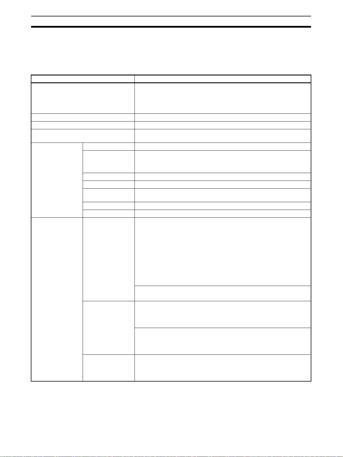
Specifications Section 1-3
1-3-5 Software Specifications
The following sof tware (sold separately) is required to use the Loop Controller:
• CX-Process Tool: Tool for preparing function block data (essential)
CX-Process Tool Specifications
Item Specification
Product name CX-Process Tool (included with CX-One)
CS1D-CPU@@P: CX-Process Tool (version 3.1 or higher)
CJ1G-CPU@@P: CX-Process Tool (version 4.0 or higher)
CX-Process Tool Version 5.2 or higher is required to use all functions of
LCB01/03/05 Version 3.5.
Model WS02-LCTC1EV3 (Ver. 5.0)
Applicable PLC-series CS/CJ-series
Applicable Unit Loop Control Unit, Loop Control Board, Process-control CPU Unit, or Loop-
Applicable computer Computer IBM PC/AT or compatible
Operating system
(OS) (See note.)
Japanese or English
Processor A processor that is recommended by Microsoft Corporation
Memory The memory that is recommended by Microsoft Corporation
Hard disk A minimum of approx. 2.8 GB is required to install all of the CX-One soft-
Monitor XGA (1,024×768) and 16-bit high color or better
Disk device CD-ROM driver or DVD-ROM drive
Connecting method Connection with
CPU Unit (or Serial
Communications
Board/Unit)
Connection via Controller Link
Connection via
Ethernet
control CPU Unit
Windows XP (Service Pack 3 or higher), Windows Vista, or Windows 7
ware.
Using the FinsGateway Serial Unit Driver
Communications protocol with PLC: Host Link (not supported on Peripheral
bus)
The computer is connected to the CPU Unit peripheral por t or built-in RS-
232C port, or RS-232C port of the Serial Communications Unit/Board.
- Connector cable: When connecting to the CPU Unit peripheral ports:
Model CS1W-CN@@@ (2 m, 6 m)
When connecting to the CPU Unit's RS-232C port: Model XW2Z-@@@-@
(2 m, 5 m)
(For details on model numbers, see 2-3 Connecting to CX-Process Tool.)
Using the CX-Server
Communications protocol with PLC: Host Link or peripheral bus
Using the FinsGateway CLK (PCI) Driver
The Driver is installed on the computer on which the PCI Controller Link
Support Board is mounted to enable communications with the PLC on
which the Controller Link Unit is mounted.
Using the FinsGateway Controller Link Driver or the CX-Server
The Driver is installed on the computer on which the ISA Controller Link
Support Board is mounted to enable communications with the PLC on
which the Controller Link Unit is mounted.
Using the FinsGateway ETH_UNIT Driver or the CX-Server
The Driver is installed on the computer on which the Ethernet Board is
mounted to enable communications with the PLC on which the Ethernet
Unit is mounted.
60
Page 93

Specifications Section 1-3
Item Specification
Offline operation functions - Setting of function block ITEM data (including System Common block set-
Online operation functions - Downloading of function block data (download/upload to and from Loop
Note Precautions on Operating Systems That Are Compatible with CX-One
(1) The required system and required hard disk space depend on the system
(2) Operation is not possible on the 64-bit edition of Windows XP.
tings)
- Software wiring of analog signals
- Pasting, displaying, and printing text-string comments (memos) in block or
ladder diagrams.
- Inputting Step Ladder Program block commands
- Inputting sequence tables
- Initializing Loop Controller memory (RAM)
Controller)
- Run/stop command for Loop Controller (all function blocks)
- System monitor run status: Monitoring/manipulation of System Common
block (Block Model 000) (including monitoring of LCB load rate)
- Loop Controller monitor run status: Confirmation of function block wiring
operation (including operation stop/stop cancel on each function block),
confirmation of Step Ladder Program operation, and validation of sequence
tables
- Autotuning PID constants and other parameters.
environment.
61
Page 94

How to Use Function Blocks for Specific Operations Section 1-4
1-4 How to Use Function Blocks for Specific Operations
To perform this specific operation Perform the following See page:
Data
Exchange
Run/Stop Instruction of run start/stop of the Loop
Highspeed processing
High-density monitor
Monitoring/ Setting
External
Controllers
Batch
Data Collection
Direct exchange of large amounts of data
between the CPU Unit and function
blocks for data exchange with a PT (Programmable Terminal) for example
Continuous data exchange with the CPU
Unit
Read/write of specified data (ITEMs) from
a CPU Unit (including a CPU Unit on a
networked PLC) whenever necessary
Reading/writing specific ITEMs for Control, Operation, and External Controller
Blocks with SCADA software
Reading/writing I/O memory in CPU Unit
using SCADA software
Controller (all function blocks) from the
CPU Unit whenever necessary
Instruction of operation stop/stop cancellation on individual function blocks from
the CPU Unit whenever necessary
Execution of required processing on the
CPU Unit according to run status (e.g. in
RUN mode, execution error, function
block data error) of the Loop Controller
Execution of required processing on the
Loop Controller according to run status
(e.g., operation mode, fatal error, Output
OFF) of the CPU Unit
To operate Loop Controllers in duplex
mode (to enable continued operation on
the other Loop Controller if one Loop
Controller has a fatal Inner Board error)
High-speed processing of specific function blocks
High-density monitoring of analog signals Monitor analog signals by the Field T erminal
Monitoring and setting a stand-alone
external controller.
Data collection by a certain timing within
sequence processing in a batch processing plant
Use the Expanded CPU Unit Terminal
Blocks (Block Models 455 to 458).
Use the CPU Unit Terminal blocks (Block
Models 451 to 454).
Execute the CMND (DELIVER COMMAND)
instruction in the Step Ladder Program, and
issue the FINS command (ITEM read/write
command).
Use HMI function to transfer Loop Controller
data using tags created with CX-Process
Tool.
Use user link tables.
Use the CSV tags generated when adding
user link tables with CS-Process Tool to
specify I/O memory addresses in CPU Unit.
Execute the CMND (DELIVER COMMAND)
instruction in the Step Ladder Program, and
issue the FINS command (ITEM read/write
command) to change ITEM 014 (run/stop
command) of the System Common block.
Or, use the ITEM setting commands (Block
Models 171 and 172) to stop ITEM 014
(run/stop command) of the System Common block. (In this case, operation cannot
be started.)
Note: Operation can also be stopped or
started on CX-Process Tool and
SCADA software.
Execute the CMND (DELIVER COMMAND)
instruction in the Step Ladder Program, and
issue the FINS command (ITEM read/write
command) to change ITEM 000 (stop block
operation command) of the relevant block.
Note: Arithmetic operation stop/stop can-
cel on a relevant block can also be
indicated by monitoring the run status on CX-Process Tool.
Execute the required processing on the
CPU Unit taking bits 00 to 05 of the nth leading words of the CPU Bus Unit as the input
conditions.
Execute the required processing on the
Loop Controller using the Sequence Table
or Step Ladder Program block based upon
the CPU Unit run status of ITEMs 007 to
011 and 013 in the System Common block.
Use two Process-control CPU Units (CS1DCPU@@P) in a CS1D Duplex System.
Set the operation cycle of the relevant function block to a shorter value.
blocks (Block Models 501 to 587) and Send
to Computer blocks (Block Models 401 to
404)
Connect an ES100X Controller to the RS-
232C port on the Loop Controller and use
the ES100X Controller Terminal (Block
Model 045). (Not supported for the CS1DCPU@@P, C J 1G - CPU @@P. )
Use the Batch Data Collector block (Block
Model 174).
Function Block Reference Manual
3-3 Exchanging Data with the
CPU Unit
3-4 Exchanging Data Using
SCADA and Other Software
3-4 Exchanging Data Using
SCADA and Other Software
3-2 Description of Operation
3-2-9 Stop Each Function Block
Operation and Cancel OperationStop
3-3 Exchanging Data with the
CPU Unit
Refer to the CS1D Duplex System
Installation Guide (Cat. No.
W350).
3-2 Description of Operation
3-2-14 Specifying the Operation
Cycle
3-4 Exchanging Data Using
SCADA and Other Software
Appendix B How to Use the
Sequence Table Block
Function Block Reference Manual
Function Block
Reference Manual
62
Page 95

How to Use Function Blocks for Specific Operations Section 1-4
To perform this specific operation Perform the following See page:
Analog
control
ON/OFF control Use the 2-position ON/OFF block (Block
Heating/cooling ON/OFF control Use the 3-position ON/OFF block (Block
Time-proportional control Use the Analog/Pulse Width Converter
Continuous proportional control for heating/cooling
Application of input filter on PV Use the First-order Lag block (Block Model
Application of bias on PV Use the Ratio Setting block (Block Model
Application of ratio on Set Point and PV
Inputting the difference between two PVs Use the Addition or Subtraction block (Block
Entry of differential pressure transmitter
to calculate flowrate
Entry of pulse output flowmeter for accumulation of flowrate
Temperature and pressure correction Use the Temperature and Pressure Correc-
Setting of the PID constant values for
multiple words
Switching of multiple Set Point values Use the Constant Selector block (Block
Switching of multiple PID sets Use the Constant Item Setting block (Block
Setting multiple SPs and PID constants,
and switching the SPs and PID constants
under certain conditions.
Examples:
• Switching set values (SPs, PID constants) according to product type.
• Switching set values (SPs, PID constants) according to time.
Ramp control of Set Point values (program control)
Cascade control Use a serial connection for the Basic PID
Dead time compensation control Use the Dead Time Compensation block
Feedforward control Use the Advanced PID block (Block Model
Non-interfering control
Sample PI control Use the ON/OFF Timer block (Block Model
Model 001).
Model 002).
block (Block Model 192).
Use with the Basic/Advanced PID block and
Split Converter block (Block Model 169).
(Supported only by Loop Control Board version 1.5)
141).
033) or the Addition/Subtraction block
(mode 121).
Model 121)
Use the Square Root block (Block Model
131) (with low-end cutout function).
Use the Pulse Input Unit, and enter to the
Accumulator for accumulated value input
block (Block Model 184) for continuous
accumulation.
tion block (Block Model 136).
Use the Constant Item Setting block (Block
Model 171).
Model 165) or the Constant Item Setting
block (Block Model 171).
Model 171).
Use the Bank Selector block (Block Model
168), and Basic PID block (Block Model
011), or Advanced PID block (Block Model
012). (Supported by LCB01/05 with version
1.5 or later and LCB03 only.)
Use the Ramp Program block (Block Model
155), the Segment Program block (Block
Model 156), the Segment Program 2 block
(Block Model 157), or the Segment Program
3 block (Block Model 158).
block (Block Model 011) or Advanced PID
block (Block Model 012).
(Block Model 149) or the Advanced PID
block (Block Model 012).
012) or the Lead/Delay block (Block Model
147).
206).
Function Block Reference Manual
5-1 Basic Examples of PID Control, 5-1-6 Time-proportional Control, and Function Block
Reference Manual
Function Block Reference Manual
5-1 Basic Examples of PID Control, 5-1-7 Monitoring and Accumulating Flowrate and Function
Block Reference Manual
Function Block Reference Manual
5-1 Basic Examples of PID Control, 5-1-2 Multi-channel PID Control and Function Block Reference
Manual
5-1 Basic Examples of PID Control, 5-1-3 PID Control for Switching Multiple Set Points and
Function Block Reference Manual
5-1 Basic Examples of PID Control 5-1-4 PID Control for Switching PID Constants by Three Set
Point Zones and Function Block
Reference Manual
• Ramp Program Block (Block
Model 155)
• Segment Program Block (Block
Model 156)
• Segment Program 2 Block
(Block Model 157)
• Segment Program 3 Block
(Block Model 158)
• 5-1 Basic Examples of PID
Control
5-2 Examples of Applied Control
Types, 5-2-1 Cascade Control
and Function Block Reference
Manual
5-2 Examples of Applied Control
Types, 5-2-4 Dead Time Compensation and Function Block Refer-
ence Manual
5-2 Examples of Applied Control
Types, 5-2-2 Feedforward Control
and Function Block Reference
Manual
5-2 Examples of Applied Control
Types, 5-2-3 Sample PI Control
and Function Block Reference
Manual
63
Page 96

How to Use Function Blocks for Specific Operations Section 1-4
To perform this specific operation Perform the following See page:
Analog
control,
continued
Special
math operations
Accumulation processing
PID control with differential gap Use the Constant Item Setting block (Block
Selective control Use the Rank Selector block (Block Model
Using fuzzy control based on knowledge
from ambiguous expressions
Suppresses influence of disturbances in
applications requiring high-speed
responses.
Performing calculation is engineering
units rather than percentages
Performing special calculations, such as
trigonometric or logarithmic operation
Calculating statistics (e.g., average, standard deviation, etc.) for time sequence
data
Accumulation (accumulator) of instantaneous analog signals such as flowrate
signals on the Loop Controller
Continuous accumulation of 4-digit accumulated value signals (repeat signals
0000 to 9999) and conversion to 8-digit
signals
Input and accumulation of low-speed
pulse signals such as the power signal
Notification of accumulated values on a
field mechanical counter for contact
inputs
Batch flowrate capture Use the Batch Flowrate Capture block
Ratio control of accumulated values Use the Batch Flowrate Capture block
Addition of accumulated values Use the Accumulated Value Input Adder
Multiplication of analog signals with accumulated values
Model 171).
161).
Use the Fuzzy Logic block (Block Model
016).
Enable disturbance overshooting control for
the Basic PID block (Block Model 011) or
Advanced PID block (Block Model 012).
Use the Arithmetic Operation block (Block
Model 126).
Use the Time Sequence Data Statistics
block (Block Model 153).
Use the Accumulator for instantaneous
value input block (Block Model 150).
Use the Accumulator for accumulated value
input block (Block Model 184).
Use the Contact input/Accumulated value
output block (Block Model 185).
Use the Accumulated Value Input/Contact
Output block (Block Model 186).
(Block Model 014).
(Block Model 014) and the Blended PID
block (Block Model 013).
block (Block Model 182).
Use the Accumulated Value Analog Multi-
plier block (Block Model 183).
Function Block Reference Manual
Function Block Reference Manual
5-1 Basic Examples of PID Control, 5-1-7 Monitoring and Accumulating Flowrate and Function
Block Reference Manual
Function Block Reference Manual
64
Page 97

How to Use Function Blocks for Specific Operations Section 1-4
To perform this specific operation Perform the following See page:
Sequence
control
Constant
setting/selection
AND, OR and other logical operations on
the Loop Controller
One-shot contact output of the ON input
state when the contact state changes
from OFF to ON and vice versa only in 1operation cycles (system common operation cycle)
Constantly ON contacts and other system
contacts
Step progression control and other control on the Loop Controller
Acceptance of bits in the Step Ladder
Program
Execution of special processing at each
fixed cycle longer than operation cycle in
Step Ladder Program
Execution of timers/counters on the Loop
Controller
Constant transmission of constants as
analog signals
Setting of constants to specified ITEMs
under certain conditions
Selection of one of multiple constants and
transmission of that constant as an analog signal
Changing PID constants and other
parameters in stages according to a process value (e.g., temperature).
Use the Sequence Table block (Block Model
302) or Step Ladder Program block (Block
Model 301).
Use the Internal Switch block (Block Model
209).
Generate a fixed cycle timing signal by the
Clock Pulse block (Block Model 207).
Use the Timer block (Block Model 205) and
the Counter block (Block Model 208).
Use the Constant Generator block (Block
Model 166).
Use the Constant Item Setting block (Block
Model 171).
Use the Constant Selector block (Block
Model 165).
Use the Level Check block (Block Model
210) and the Constant ITEM Setting block
(Block Model 171) together to change
parameters for other blocks according to the
level.
Appendix A How to Use the Step
Ladder Program Block, Appendix
B Step Tables, and Function
Block Reference Manual
Function Block Reference Manual
3-1 Configuration of Function
Blocks and Function Block Reference Manual
Function Block Reference Manual
65
Page 98

Basic Procedure for Using the Loop Controller Section 1-5
To perform this specific operation Perform the following See page:
Analog
signal setting/selection
Manipulation/monitor/control
of special
external
control target
Setting of analog signals to specified
ITEMs under certain conditions
Selection of one of multiple analog signals and transmission of that analog signal as an analog signal
Selection of the maximum value from
multiple analog signals and transmission
of that maximum value as an analog signal
Selection of the minimum value from multiple analog signals and transmission of
that minimum value as an analog signal
Selection of the nth largest value from
multiple analog signals and transmission
of the signal as an analog signal
Switching of sensors on a different measuring system or measurement target
Switching of operation nodes on a different measuring system or measurement
target
Changing two settings with a ramp (e.g.,
opening and closing valves)
Converting ranges of analog signals
merely by setting values for 0% and
100% inputs and 0% and 100% outputs
Comparison of constant and analog signals
Comparison of two analog signals Use the Variable Comparator block (Block
Manipulation and monitoring of ON/OFF
valve with open/close limit switches
Manipulation and monitoring of motors Use the Motor Manipulator block (Block
Manipulation and monitoring of reversible
motors
Manipulation of a electric positional-proportional motor as the control target
Use the Variable ITEM Setting block (Block
Model 171).
Use the Input Selector block (Block Model
162).
Use the Rank Selector block (Block Model
161).
Use the 3-input Selector block (Block Model
163).
Use the 3-output Selector block (Block
Model 164).
Use the Ramped Switch block (Model Block
167).
Use the Range Conversion block (Block
Model 127).
Use the Constant Comparator block (Block
Model 202).
Model 203).
Use the ON/OFF Valve Manipulator block
(Block Model 221) and Switch Meter block
(Block Model 225).
Model 222) and Switch Meter block (Block
Model 225).
Use the Reversible Motor Manipulator block
(Block Model 223).
Use the Basic PID (Block Model 011)/
Advanced PID block (Block Model 012) and
Motor Opening Manipulator block (Block
Model 224) and Switch Meter block (Block
Model 225).
3-1 Configuration of Function
Blocks and Function Block Reference Manual
Function Block Reference Manual
1-5 Basic Procedure for Using the Loop Controller
This section describes the basic procedure for using the Loop Controller.
For ex amples of actual procedures, see Section 4 Simple Examples of Use.
1. Design
1,2,3... 1. Prepare an instrumentation drawing.
PIDPV MV
See this Section (for understanding which functions can be used on the
Loop Controller).
See Section 5 Examples of Function Block Combinations.
66
Page 99

Basic Procedure for Using the Loop Controller Section 1-5
A
k
2. Decide on the PLC system configuration.
This mainly involves selection of the Analog Input and Output Units.
See 1-2 Configuration of Instrumentation System.
See Section 3 Mechanism of the Loop Controller.
3. Select the required function blocks.
See 1-4 How to Use Function Blocks for Specific Operations.
See Section 3 Mechanism of the Loop Controller.
4. Decide on the function block system configuration.
Analog i nput
nalog output
AI 4-point/AO
4-point Terminal
PV
MV
5. Assess the LCB load rate and the ex ternal I/O response cycle.
See 1-2 Configuration of Instrumentation System.
See 3-2 Description of Operation.
6. Assess fail-safe countermeasures.
See 3-5 Fail-safe Countermeasure Guidelines.
2. Preparing Function Block Data (by CX-Process Tool)
1,2,3... 1. Set up and start CX-Process Tool.
Prepare the function bloc
data on CX-Process Tool
running on the computer.
Refer to CX-Process Tool Operation Manual.
2. Set the System Common block data.
(For example, set the operation cycle and leading Data Memor y address
for the Node Terminals.)
Refer to the Function Block Reference Manual.
3. In CX-Process Tool, wire the analog signals between the Selector blocks
(analog signals and accumulated value signals only).
Refer to the CX-Process Tool Operation Manual.
4. Set the ITEMs in each function block.
(If necessary , prog ram step ladder commands in the Step Ladder Progr am
block including contact signals.)
Refer to CX-Process Tool Operation Manual.
Refer to the Function Block Reference Manual.
Basic PID
Block
Model 011
Note Set function block initial setting parameters (refer to the item “(S): Initial set-
ting data” describing how to read/write in the Function Block Reference Man-
ual) on CX-Process Tool.
67
Page 100

Basic Procedure for Using the Loop Controller Section 1-5
5. Using SCADA Software
Set the CSV tags and create the CSV tag files.
Refer to the CX-Process Tool Operation Manual.
3. Setting up the Loop Controller and Other I/O Units
1,2,3... 1. Mount the Loop Controller and wire the Analog Input and Output Units.
The Loop Controller itself need not be wired.
See 2-2 Insta llation and refer to the manual for other Analog Input and Out-
put Units.
2. Set the unit number setting switch on the front panel of the Units.
3. Connect the Programming Devices.
Refer to Programming Devices (CX-Programmer or Programming Con-
sole) Operation Manual.
Note For CS1D CPU Units when the CS1D-LCB05D is being used, co nnect to the
active CPU Unit.
4. Turn power ON to the PLC.
5. Create I/O tables using the Programming Devices.
Refer to the Programming Devices (CX-Programmer or Programming
Console) Operation Manual.
6. If necessary, set the communications conditions of the seria l commun ications port in the PLC Setup using the Programming Devices.
Refer to the Programming Devices (CX-Programmer or Programming
Console) Operation Manual.
7. Set the allocated Data Memory (D) on the Analog Input and Output Units
using the Programming Devices.
Refer to the Analog Input and Output Unit manuals.
4. Downloading the function block data to the Loop Controller
1,2,3... 1. Turn power OFF to the PLC.
2. Set the unit number setting switch on the front panel of the CPU Unit.
Refer to the CS1 PLC Operation Manual.
3. Connect the CPU Unit to the computer on which CX-Process Tool is r unning.
4. Turn the PLC ON.
5. Set the network address (000) and node address (01).
Refer to the CX-Process Tool Operation Manual.
6. Perf orm the Host Link connection oper ation on CX-Process Tool (File - Ini-
tialize Serial Port).
Refer to the CX-Process Tool Operation Manual.
7. Download the function block data to the Loop Controller specified in the
Function Block Data Sheet of CX-Process Tool (Execute - Download).
Refer to the CX-Process Tool Operation Manual.
68
 Loading...