

Page 1
SMART PRESSURE TRANSMITTER
HIGH STABILITY, LOW DRIFT
PX751 Series
25 inH2O to 6000 psi
Starts at
$
1875
PX751, $1875,
shown smaller
than actual size.
2-Way Communications,
⻬
Remote
Reranging,
Access to Difficult-to-Reach
or Hazardous Areas
⻬ Improved Performance,
Increased Accuracy,
Greater Stability and
Noise Resistance
⻬ Diagnostic Capabilities,
Continuous On-Line
Self-Check, Selectable
Failure Alarm, Loop Test
⻬ Transmitter Data Base
Includes Configuration,
Calibration, and Materials
⻬ Greater Performance,
Wider Rangeability (100:1),
Transmitter Security,
Selectable Linear/Square
Root Output, Multi-Drop
⻬ High Stability and Low
Drift Ensure Accurate
Measurements for Years
⻬ Fast, Dynamic Response
⻬ Tighter Control
and Reduced
Maintenance Costs
⻬ Pressure and
Temperature Output
Troubleshooting,
Reconfiguring,
Coplanar Design—
Differential, Gage, or
Absolute Pressure!
PX751C coplanar transmitter,
$1875, with flange, $150, shown
smaller than actual size.
B-235
Page 2

PX751C SMART TRANSMITTER
LCD Meter Options
The LCD meter can be digitally
customized by the user to meet
process needs. The meter can be
configured to display engineering
units, percent of range, or custom
user scale, or to alternate between
any 2 of these.
Power Supply
The DC power supply should
provide power with less than 2%
ripple. The transmitter requires a
minimum of 250 Ω of loop resistance
to communicate with a HartTMbased
communicator. With 250 Ω drop, the
transmitter will require a minimum of
16 Vdc to output 20 mA.
Diagnostics and Service
The diagnostic and service functions
listed here are primarily for use after
the transmitter is installed in the field.
The Transmitter Test feature helps
verify that the transmitter is
operating properly, and can be
performed either on the bench or in
the field. The transmitter test
command initiates an extensive
diagnostics routine that can quickly
identify potential electronics
problems. If the transmitter detects
a problem, messages to indicate the
source of the problem are displayed
on the communicator screen.
The Loop Test feature is designed
to verify proper loop wiring and
transmitter output, and should only
be performed after the user installs
the transmitter. This function tests
the output of the transmitter, the
integrity of the loop, and the
operations of any recorders or
similar devices installed in the loop.
Calibration
Calibrating a smart transmitter is
different from calibrating an analog
transmitter. The smart transmitter
requires 3 steps:
⻬ Rerange—sets the 4 and 20 mA
points to the desired pressures.
⻬ Sensor Trim—adjusts the
position of the factory
characterization curve to optimize
the transmitter performance over a
specified pressure range or to
adjust for mounting effects.
PX751C
(Shown Installed with 3-Valve Manifold)
⻬ Analog Output Trim—adjusts the
analog output to match the plant
standard or the control loop.
Advanced Functions
Cloning: Quickly copies the same
configuration to multiple units. The
cloning process involves configuring
a transmitter, saving the configuration
data, then sending a copy of the
data to a separate transmitter.
Multidrop: Communication
between the host and the
transmitter takes place digitally with
the analog output of the transmitter
deactivated. With HartTMsmart
protocol, up to 15 units can be
connected on a single pair of twisted
wires or over leased phone lines.
B
Burst Mode: Provides faster digital
communications to control system
by eliminating the time required
for the control system to request
data from the transmitter. Burst
mode applies only to the
transmission of dynamic data
(pressure and temperature).
Low-Power Option
User-selectable
3-wire 1 to 5 Vdc or 0.8 to 3.2 Vdc
outputs are available with the
low-power option. The digital signal
is superimposed on the voltage
signal, available to any host
conforming to HartTMprotocol.
Low-power units operate on
6 to 12 Vdc with no load.
B-236
Page 3
PX751C SMART TRANSMITTER
SPECIFICATIONS AND REFERENCE DATA
Specifications
Service:
Liquid, gas and vapor applications
Zero and Span Adjustment:
Zero and span values can be set anywhere
within the range limits stated in tables.
Span values must be greater than or
equal to the minimum span stated in the
range limits tables.
4 to 20 mA Models
Output:
2-wire 4 to 20 mA output, user selectable
for linear or square root; digital process
variable superimposed on 4 to 20 mA
signal, available to any host that conforms
to the HartTMprotocol
Power Supply:
External power supply required. Standard
transmitter operates on 10.5 to 55 Vdc
with no load. A minimum of 250 Ω of loop
resistance is required to communicate
with a Hart
TM
based communicator. With
250 Ω drop, the transmitter will require a
minimum of 16 Vdc to output 20 mA.
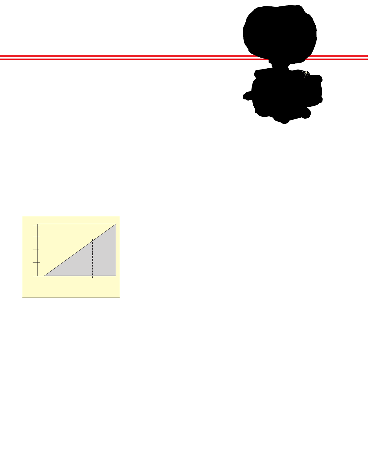
Load Limitations:
)
Load (Ω
1935
1500
1000
500
0
10.5 20 30 40 55
Communications require a minimum loop
resistance of 250 Ω.
1
For CSA approval, power supply must not
exceed 42.2 V.
Operating Region
Voltage (Vdc)
42.4
1
Low Power Models
Output: 3-wire 1 to 5 Vdc or 0.8 to 3.2 Vdc
user selectable. Also user selectable for
linear or square root output configuration.
Digital process variable superimposed on
4 to 20 mA signal, available to any host
that conforms to the HartTMprotocol.
Power Consumption:
3 mA, 18 to 36 mW
Minimum Load Impedance:
100 kΩ (V
Indication:
Optional 2-line, 5-digit LCD meter
Overpressure Limits: Transmitters
withstand the following limits without
damage:
Gage/Differential Models (CA/CD):
Range 1:
0 to 2000 psig (0 to 13.8 MPa)
Ranges 2 to 5:
0 to 3626 psig (0 to 25 MPa)
OUT
+ wiring)
Absolute Models (CA):
Range 0: 0 to 60 psia (0 to 413.7 kPa)
Range 1: 0 to 120 psia (0 to 827.4 kPa)
Range 2: 0 to 300 psia (0 to 2070 kPa)
Range 3: 0 to 1600 psia (0 to 11030 kPa)
Range 4: 0 to 6000 psia (0 to 41370 kPa)
High-Process Temperature
Models (HP/HG)
All Ranges, 0 to 3626 psig
(0 to 25 MPa) “T” Style Gage and
Absolute Models (TA/TG):
Range 1: 0 to 750 psia (0 to 5.2 MPa)
Range 2: 0 to 1500 psia (0 to 10.3 MPa)
Range 3: 0 to 1600 psia (0 to 11.0 MPa)
Range 4: 0 to 6000 psia (0 to 41.4 MPa)
Range 5: 0 to 15000 psia (0 to 103.4 MPa)
Static Pressure Limits
Differential Pressure Models Only:
Operates within specification between
static line pressure of 0.5 psia and
3626 psig; 2000 psig for range 1 (ranges
2 and 3 for high-accuracy models)
Burst Pressure Limits:
All Except Type T:
10,000 psig (69 MPa)
Type T:
Ranges 1 to 4: 11,000 psi (75.8 MPa)
Range 5: 26,000 psig (179 MPa)
Failure Mode Alarm: User selectable to
drive output either high or low when gross
transmitter failure is detected
Temperature Limits
Ambient: -40 to 85°C (-40 to 185°F);
with integral meter, -20 to 80°C (-4 to 175°F)
Storage: -46 to 110°C (-50 to 230°F);
with integral meter, -40 to 85°C (-40 to 185°F)
Process Temperature Limits
Differential, Gage and Absolute:
Silicone Fill Sensor1with
Coplanar Flange -40 to 250°F
Side Flange -40 to 300°F
Level Flange
Horizontal Mount -40 to 250°F
Vertical Mount -40 to 300°F
Inert Fill Sensor Option10 to 185°F
High-Temperature Models:
Fill Material Temperature Range
D.C. Silicone 200
Inert -50 to 350°F
Neobee M-20
Type “T” Gage and Absolute:
Silicone Fill Sensor
Inert Fill Sensor
1
1
1
1
-40 to 375°F
0 to 375°F
-40 to 250°F
-22 to 250°F
Humidity: 0 to 100% RH
Turn-On Time: Performance within
specifications less than 2.0 seconds after
power is applied
Volume Displacement:
<0.08 cm
3
(0.005 in3)
Damping: User selectable from
0 to 36 seconds for one time constant.
This software damping is in addition to
sensor module response time.
3, 4
2
2
2
2
2
2
PX751H high-process temperature
traditional flange differential and
pressure gage, $2860, shown
smaller than actual size.
All Models
Response Time:
Dead Time (Td): 45 ms nominal
Time Constant (Tc): 55 ms
Update Rate: 20 times/s minimum
Vibration Effect: < ±0.1% of URL per
gram when tested from 15 to 2000 Hz
in any axis relative to pipe-mounted
process connection
Power Supply Effect:
<0.005% of calibrated span per volt
RFI Effects: ±0.1% of span from 20 to
1000 MHz, and field strength up to 30 V/m
Transient Protection (Optional):
Meets IEEE standard 587, Category B
meets IEEE standard 473,
surge withstand capability 2.5 kV crest,
1 MHz waveform
Process Connections (All Except
Level, High-Pressure Gage and
Absolute Models):
1
⁄4-18 NPT on 21⁄8" centers;
1
⁄2-14 NPT on 2, 21⁄8, or 21⁄4" centers
Level Models:
High-Pressure Side: 2, 3 or 4",
Class 150, 300 or 600 flange
50, 80 or 100 mm: PN40 or
High Gage or Absolute Pressure:
1
⁄4-18, 1⁄2-14 female, G1⁄2 A DIN 16288
male (available in stainless steel for
ranges 1 to 4) or autoclave type F-250-C
(pressure relieved
1
⁄4 OD high pressure tube 60° cone;
9
⁄16-18 gland thread;
available in stainless steel for range 5 only)
Wetted Parts:
Flanges: Plated carbon steel standard;
stainless steel, Hastelloy C or Monel
optional (available on PX751C only)
Wetted O-Rings: Glass-filled TFE
Housing: Low-copper aluminum with
polyurethane paint
Cover O-Rings: Buna-N
Note: Calibrations at 20°C (68°F) per
ANSI Z210.1
1
Process temperatures above 185°F (85°C)
require derating the ambient limits by a 1.5:1
ratio (0.06:1 ratio for Type H).
2
104°C ( 220°F) limit in vacuum service;
71°C (130°F) for pressures below 0.5 psia.
3
71°C (160°F) limit in vacuum service.
4
Not available on model PX751CA.
10
⁄16 flange
B-237
Page 4

COMMERCIAL GRADE—TYPE “C”
DIFFERENTIAL, GAGE, AND ABSOLUTE PRESSURES
Specifications
Differential and Gage CD/CG Models
Accuracy: ±0.075% of span ±0.100%
of span for differential range 1. For
rangedowns greater than 10:1 of URL
(15:1 for differential range 1), accuracy
= ±[0.025 + 0.005 ( URL
Ambient Temperature Effect
per 10°C (50°F):
Spans 1:1 to 10:1:
±(0.0125% URL + 0.0625% span)
Spans 10:1 to 100:1
±(0.025% URL + 0.125% span)
Range 1: ±(0.1% URL + 0.25% span)
Static Pressure Effect
(DP Model Only):
Zero Error: ±0.1% of URL/1000 psi
(6.9 MPa) for line pressures from
0 to 2000 psi (0 to 13.7 kPa)—can be
calibrated out at line pressure;
±0.2% of URL/1000 psi (6.9 MPa) for
line pressure above 2000 psi (13.7 MPa)
Range 1:
±0.25% URL/1000 psi (6.9 MPa)
Span Error*:
±0.2% rdg/1000 psi (6.9 MPa)
Range 1:
±0.4% rdg/1000 psi (6.9 MPa)
*Ranges 4 and 5 must be field calibrated
Total Performance**:
±0.25% of span for ±28°C (50°F)
temperature changes, up to
1000 psi (6.9 MPa) line pressure,
from 1:1 to 5:1 rangedown
** Total performance is based on the
combined errors of reference accuracy,
ambient temperature effect, and span line
pressure effect.
Stability: ±0.25% of URL for 5 years
for ±28°C (50°F) temperature changes,
up to 1000 psi (6.9 MPa) line pressure
Range 1: ±0.2% URL for 1 year
Mounting Position Effect:
Zero shifts up to 2.5 inH
(0.62 kPa), which can be calibrated out;
no span effect
Weight:
Type C: 6.0 lb (2.7 kg)
Span
RANGES: PX751CD, CG, PD, PG, HD, HG, AND LEVEL MODELS
R
A
N
G
E
1
2
3
4
5
MINIMUM SPAN UPPER RANGE AND SENSOR LIMITS
GAGE AND HIGH-
DIFFERENTIAL
TYPE C TYPE H MODELS CD/HD CG/HG DIFFERENTIAL GAGE HD HG
0.5 inH
(0.12 kPa) (6.22 kPa) (-6.22 kPa)
2.5 inH
(0.62 kPa) (0.62 kPa) (62.2 kPa) (-62.2 kPa) (-62.2 kPa) (-62.2 kPa) (-62.2 kPa) (-62.2 kPa) (-62.2 kPa)
10 inH
(2.48 kPa) (24.8 kPa) (248 kPa) (-248 kPa) (3.5 kPa abs) (-248 kPa) (3.5 kPa abs) (-248 kPa) (3.5 kPa abs)
3 psi 30 psi 300 psi -300 psi 0.5 psia -300 psi 0.5 psia -300 psi 0.5 psia
(20.7 kPa) (207 kPa) (2070 kPa) (-2070 kPa) (3.5 kPa abs) (-2070 kPa) (3.5 kPa abs) (-2070 kPa) (3.5 kPa abs)
20 psi 200 psi 2000 psi -2000 psi 0.5 psia
(138 kPa) (1380 kPa) (13800 kPa) (-13800 kPa) (3.5 kPa abs) (-13800 kPa) (3.5 kPa abs)
ACCURACY
O
2
O 2.5 inH2O 250 inH2O -250 inH2O -250 inH2O -250 inH2O -250 inH2O -250 inH2O -250 inH2O
2
O 100 inH2O 1000 inH2O -1000 inH2O 0.5 psia -1000 inH2O 0.5 psia -1000 inH2O 0.5 psia
2
N/A
)
O
2
% of span
]
PX751CD coplanar
design, $2040, shown
smaller than actual size.
RANGES: PX751CA
ABSOLUTE PRESSURE MODELS
RANGE MINIMUM UPPER LOWER
0
1
2
3
4
(URL) LOWER (LRL)
ALL DIFFERENTIAL GAGE LEVEL LEVEL HIGH-TEMP HIGH-TEMP
25 inH2O -25 inH2O
SPAN (URL) (LRL)
0.167 psia 5 psia 0 psia
(8.7 mmHgA) (26 mmHgA) (0 mmHgA)
0.3 psia 30 psia 0 psia
(2.07 kPa) (206.8 kPa) (0 kPa)
1.5 psia 150 psia 0 psia
(10.34 kPa) (1034.2 kPa) (0 kPa)
8 psia 800 psia 0 psia
(55.16 kPa) (5515.8 kPa) (0 kPa)
40 psia 4000 psia 0 psia
(275.8 kPa) (27580 kPa) (0 kPa)
RANGE AND SENSOR LIMITS
** Total performance is based
on the combined errors of
reference accuracy, ambient
temperature effect, and span
line pressure effect.
N/A N/A N/A N/A N/A
N/A N/A
-2000 psi 0.5 psia
B
B-238
Page 5

COMMERCIAL GRADE—TYPE “C”
HIGH-PRECISION GRADE—TYPE “P”
ORDERING GUIDE
Vacuum to 2000 psi
⻬ Coplanar Flange
⻬ Plated Carbon Steel
Flange
⻬ Stainless Steel
Diaphragm
⻬ 0.075% Accuracy
⻬ 0.25% Long-Term
(5-Year) Stability
⻬ 5-Year Calibration Cycle
PX751C coplanar transmitter,
$1875, with flange, $150, shown
smaller than actual size.
COMMERCIAL GRADE—TYPE C
AVAILABLE FOR FAST DELIVERY!
To Order (Specify Model Number)
MODEL NO. PRICE URL COMPATIBLE METERS
ABSOLUTE PRESSURE
PX751CA-1 $2310 30 psia DP41-E, DP25B-E, DP24-E
PX751CA-2 2310 150 psia DP41-E, DP25B-E, DP24-E
PX751CA-3 2310 800 psia DP41-E, DP25B-E, DP24-E
PX751CA-4 2310 4000 psia DP41-E, DP25B-E, DP24-E
GAGE PRESSURE
PX751CG-2 $1875 250 inH2O DP41-E, DP25B-E, DP24-E
PX751CG-3 1875 1000 inH2O DP41-E, DP25B-E, DP24-E
PX751CG-4 1875 300 psig DP41-E, DP25B-E, DP24-E
PX751CG-5 1875 2000 psig DP41-E, DP25B-E, DP24-E
DIFFERENTIAL PRESSURE
PX751CD-1 $2330 25 inH2O DP41-E, DP25B-E, DP24-E
PX751CD-2 2040 250 inH2O DP41-E, DP25B-E, DP24-E
PX751CD-3 2040 1000 inH2O DP41-E, DP25B-E, DP24-E
PX751CD-4 2245 300 psid DP41-E, DP25B-E, DP24-E
PX751CD-5 2305 2000 psid DP41-E, DP25B-E, DP24-E
Standard features include plated carbon steel flange, stainless steel diaphragm, 4 to 20 mA
output with digital signal based on HartTMprotocol, glass-filled TFE O-ring and silicone fill fluid.
Ordering Examples: PX751CD-1-B4, smart differential pressure sensor with coplanar flange
and range of -2.5 to 25 inH2O, 2" pipe mounting bracket, $2330 + 50 = $2380.
PX751CG-2-B4, smart gage pressure sensor with coplanar flange and range of
-25 to 250 inH2O, 2" pipe mounting bracket, $1875 + 50 = $1925.
PX751C coplanar
design, $1875, shown
smaller than actual size.
OPTIONS FOR ALL MODELS AND INTEGRAL 2-, 3-, or 5-VALVE MANIFOLDS
SUFFIX PRICE DESCRIPTION
-M $100 Low power 1 to 5 Vdc (not avail. w/haz location cert)
-SS 150 All stainless steel flanges for Type “C”
-IN 155 Inert fill fluid (N/A on CA models)
-B4 50 2" pipe mounting bracket for coplanar flange
-B6 70 2" pipe mounting bracket for H-style transmitters
-M5 275 51⁄2 digit LCD meter
B-239
Page 6

HIGH PROCESS TEMPERATURE—TYPE “H”
DIFFERENTIAL AND GAGE PRESSURES
ALL STAINLESS STEEL FLANGES
Starts at
$
2475
Vacuum to 2000 psi
⻬ Stainless Steel Side
Flanges Standard
⻬ Process Temperatures
to 191°C (375°F) with
No Isolating Elements
⻬ 4 to 20 mA and Digital
Communications
⻬ 0.075% Accuracy
⻬ 100:1 Rangedown
⻬ Long-Term Stability
⻬ D.C. 200 Silicone
Fill Fluid
SPECIFICATIONS
“H”—High-Process Temperature
Accuracy: ±0.075% of span; for
rangedowns greater than 10:1 of URL,
accuracy =
±[0.025 + 0.005(URL
Span
Ambient Temperature Effect
per 10° C (50°F):
±(0.025% URL + 0.125% span + 0.35 inH2O);
for spans below 30:1 rangedown,
±(0.035% URL + 0.125% span + 0.35 inH2O)
Static Pressure Effect:
Zero Error: ±0.1% of URL/1000 psi
(6.9 MPa) for line pressures from
0 to 2000 psi (0 to 13.7 MPa)—can be
calibrated out at line pressure;
±0.2% of URL/1000 psi (6.9 MPa)
for line pressures above 2000 psi
(13.7 MPa)
Span Error*:
±0.2% of rdg/1000 psi (6.9 MPa)
* Ranges 4 and 5 must be field calibrated.
Stability:
Ranges 2 and 3:
±0.1% of URL
for 12 months
Ranges 4 and 5:
±0.2% of URL
for 12 months
Mounting Position Effect:
Zero shifts up to 5 inH
which can be calibrated out;
no span effect
Weight: 6.2 kg (13.6 lb)
% of span
]
)
O (1.27 kPa),
2
PX751H, high-process
temperature flange,
$2475, shown with
standard stainless steel
side flanges, smaller
than actual size.
AVAILABLE FOR FAST DELIVERY!
To Order (Specify Model Number)
MODEL NO. PRICE RANGE (psi) COMPATIBLE METER
GAGE PRESSURE
PX751HG-2 $2475 250 inH2O DP41-E, DP25B-E, DP24-E
PX751HG-3 2475 1000 inH2O DP41-E, DP25B-E, DP24-E
PX751HG-4 2475 300 psi DP41-E, DP25B-E, DP24-E
PX751HG-5 2475 2000 psi DP41-E, DP25B-E, DP24-E
DIFFERENTIAL PRESSURE
PX751HD-2 $2590 250 inH2O DP41-E, DP25B-E, DP24-E
PX751HD-3 2590 1000 inH2O DP41-E, DP25B-E, DP24-E
PX751HD-4 2750 300 psi DP41-E, DP25B-E, DP24-E
PX751HD-5 2860 2000 psi DP41-E, DP25B-E, DP24-E
Standard features include stainless steel side flanges, stainless steel diaphragm, 4 to 20 mA output
with digital signal based on HartTMprotocol, glass-filled TFE O-ring and D.C. 200 silicone fill fluid.
Ordering Examples: PX751HD-2-B6, smart high-process temperature differential pressure
sensor with stainless steel side flanges, D.C. 200 silicone fill and ranging of 2.5 to 250 inH2O and
2" pipe mounting bracket, $2590 + 70 = $2660.
PX751HG-4-B6, smart high-process temperature gage pressure sensor with stainless steel
side flange, D.C. 200 silicone fill fluid, 2" pipe mounting bracket and range of 3 to 300 psi,
$2475 + 70 = $2545.
OPTIONS FOR ALL MODELS
SUFFIX PRICE DESCRIPTION
-M $100 Low power 1 to 5 Vdc (not avail. w/haz location cert)
-SS 155 All stainless steel flanges for differential pressure
-IN 155 Inert fill fluid (N/A on CA models)
-B4 50 2" pipe mounting bracket for coplanar flange
-B6 70 2" pipe mounting bracket for H-style transmitters
-M5 275 51⁄2 digit LCD meter
B
B-239A
Page 7

SINGLE ISOLATOR—TYPE “T”
DIFFERENTIAL, GAGE, AND
ABSOLUTE PRESSURES
PX751TG, TA GAGE
AND ABSOLUTE
PRESSURE
Vacuum to 10,000 psi
⻬ Gage or Absolute Pressure
⻬ 0.075% Accuracy
⻬ All Stainless Steel
Wetted Parts
⻬ 0.25% Long-Term
(5-Year) Stability
SPECIFICATIONS
“T” Style Gage and Absolute:
Accuracy: ±0.075% of span;
for rangedowns greater than
10:1 of URL, accuracy =
±[0.0075 ( URL
For Absolute Range 0 With Turndown:
>5:1 of URL, accuracy =
±
0.025 + 0.01( URL
[
Total Performance
(Ranges 1 to 4 Only)**:
±0.25% of span for 28°C (±50°F)
temperature changes, from 1:1 to 5:1
rangedown
** Total performance is based on the
combined errors of reference accuracy,
ambient temperature effect, and span line
pressure effect.
Ambient Temperature Effect
per 10°C (50°F):
Spans 1:1 to 30:1:
±(0.025% URL + 0.125% span)
Spans 30:1 to 100:1:
±(0.035% URL + 0.125% span)
Range 0: ±(0.1% URL + 0.25% span)
Range 5: ±(0.1% URL + 0.15% span)
For High-Gage and Absolute
Range 1, Spans 1:1 to 10:1:
±(0.025% URL + 0.125% span)
Spans 10:1 to 100:1:
±(0.05% URL + 0.125% span)
Stability—Low Absolute Model:
Ranges 1 to 5:
±0.1% of URL for 12 months
Ranges 0:
±0.2% of URL for 12 months
Stability—High-Gage
and Absolute Models:
±0.25% of span
for 5 years for
28°C (±50°F)
temperature change
Mounting Position Effect: Zero shifts
up to 0.62 kPa (0.09 psi),
which can be calibrated out;
no span effect
Weight:
1.4 kg (3.0 lb)
Span
)
Span
% of span
]
% of span
]
)
Starts at
$
1680
PX751T, gage or absolute pressure
single input design, 1⁄2 NPT stainless
steel fitting, $2100, shown with meter
option, smaller than actual size.
RANGE AND SENSOR LIMITS
RANGE MINIMUM UPPER LOWER
SPAN (URL) (LRL)
1 0.3 psia (2 kPa) 30 psi (207 kPa) 0 psi (0 kPa)
2 1.5 psi (2.07 kPa) 150 psia (1034 kPa) 0 psi (0 kPa)
3 8 psi (55 kPa) 800 psia (5516 kPa) 0 psi (0 kPa)
4 40 psi (276 kPa) 4000 psia (27,579 kPa) 0 psi (0 kPa)
5 2000 psi (13,800 kPa) 10,000 psia (68,948 kPa) 0 psi (0 kPa)
AVAILABLE FOR FAST DELIVERY!
To Order (Specify Model Number)
MODEL NO. PRICE URL COMPATIBLE METERS
ABSOLUTE PRESSURE
PX751TA-1 $2100 30 psia DP41-E, DP25B-E, DP24-E
PX751TA-2 2100 150 psia DP41-E, DP25B-E, DP24-E
PX751TA-3 2100 800 psia DP41-E, DP25B-E, DP24-E
PX751TA-4 2100 4000 psia DP41-E, DP25B-E, DP24-E
PX751TA-5 2275 10,000 psia DP41-E, DP25B-E, DP24-E
GAGE PRESSURE
PX751TG-1 $1680 30 psig DP41-E, DP25B-E, DP24-E
PX751TG-2 1680 150 psig DP41-E, DP25B-E, DP24-E
PX751TG-3 1680 800 psig DP41-E, DP25B-E, DP24-E
PX751TG-4 1680 4000 psig DP41-E, DP25B-E, DP24-E
PX751TG-5 1850 10,000 psig DP41-E, DP25B-E, DP24-E
Standard features include SS diaphragm and 1⁄2 NPT process fitting, 4 to 20 mA output with
digital signal based on HartTMprotocol, glass-filled TFE O-ring and silicone fill fluid.
Ordering Examples: PX751TA-1-B4, smart absolute pressure sensor with stainless steel
input and range of 0.03 to 30 psia and 2" pipe mounting bracket, $2100 + 50 = $2150.
PX751TG-2-B4, smart gage pressure sensor with stainless steel input and range of
1.5 to 150 psig and 2" pipe mounting bracket, $1680 + 50 = $1730.
OPTIONS FOR ALL MODELS
SUFFIX PRICE DESCRIPTION
-M $100 Low power 1 to 5 Vdc (not avail. w/haz location cert)
-SS 150 All stainless steel flanges for Type “C”
-IN 155 Inert fill fluid (N/A on CA models)
-B4 50 2" pipe mounting bracket for coplanar flange
-B6 70 2" pipe mounting bracket for H-style transmitters
-M5 275 51⁄2 digit LCD meter
B-239B
Page 8

One Omega Drive | Stamford, CT 06907 | 1-888-TC-OMEGA (1-888-826-6342) | info@omega.com
EPG05
www.omega.com
UNITED KINGDOM
www. omega.co.uk
Manchester, England
0800-488-488
UNITED STATES
www.omega.com
1-800-TC-OMEGA
Stamford, CT.
CANADA
www.omega.ca
Laval(Quebec)
1-800-TC-OMEGA
GERMANY
www.omega.de
Deckenpfronn, Germany
0800-8266342
Karviná, Czech Republic
FRANCE
www.omega.fr
Guyancourt, France
088-466-342
CZECH REPUBLIC
www.omegaeng.cz
596-311-899
BENELUX
www.omega.nl
Amstelveen, NL
0800-099-33-44
More than 100,000 Products Available!
Temperature
Calibrators, Connectors, General Test and Measurement
Instruments, Glass Bulb Thermometers, Handheld Instruments
for Temperature Measurement, Ice Point References,
Indicating Labels, Crayons, Cements and Lacquers, Infrared
Temperature Measurement Instruments, Recorders Relative
Humidity Measurement Instruments, RTD Probes, Elements
and Assemblies, Temperature & Process Meters, Timers and
Counters, Temperature and Process Controllers and Power
Switching Devices, Thermistor Elements, Probes and
Assemblies,Thermocouples Thermowells and Head and Well
Assemblies, Transmitters, Wire
Flow and Level
Air Velocity Indicators, Doppler Flowmeters, Level
Measurement, Magnetic Flowmeters, Mass Flowmeters,
Pitot Tubes, Pumps, Rotameters, Turbine and Paddle Wheel
Flowmeters, Ultrasonic Flowmeters, Valves, Variable Area
Flowmeters, Vortex Shedding Flowmeters
pH and Conductivity
Conductivity Instrumentation, Dissolved Oxygen
Instrumentation, Environmental Instrumentation, pH
Electrodes and Instruments, Water and Soil Analysis
Instrumentation
Data Acquisition
Auto-Dialers and Alarm Monitoring Systems,
Communication Products and Converters, Data
Acquisition and Analysis Software, Data Loggers
Plug-in Cards, Signal Conditioners, USB, RS232, RS485
and Parallel Port Data Acquisition Systems, Wireless
Transmitters and Receivers
Pressure, Strain and Force
Displacement Transducers, Dynamic Measurement
Force Sensors, Instrumentation for Pressure and Strain
Measurements, Load Cells, Pressure Gauges, Pressure
Reference Section, Pressure Switches, Pressure Transducers,
Proximity Transducers, Regulators,
Strain Gages, Torque Transducers, Valves
Heaters
Band Heaters, Cartridge Heaters, Circulation Heaters,
Comfort Heaters, Controllers, Meters and Switching
Devices, Flexible Heaters, General Test and Measurement
Instruments, Heater Hook-up Wire, Heating Cable
Systems, Immersion Heaters, Process Air and Duct,
Heaters, Radiant Heaters, Strip Heaters, Tubular Heaters
click here to go to the omega.com home page
 Loading...