

Page 1
R
R
PX726A
Industrial Pressure Transmitter
R
R
R
R
R
R
R
R
R
R
R
R
R
R
M
An OMEGA Technologies CompanyAn OMEGA Technologies Company
E
R
Operator's Manual
Operator's Manual
M-3601/1101
M-3601/1101
Page 2

Page 3
Remove the Packing List and verify that you have received all equipment, including the following
(quantities in parentheses):
PX725A Gauge Pressure Transmitter (1)
Operator’s Manual (1)
If you have any questions about the shipment, please call the OMEGA Customer Service
Department.
When you receive the shipment, inspect the container and equipment for signs of damage. Note
any evidence of rough handling in transit. Immediately report any damage to the shipping agent.
Page 4

M-3601
GAUGE PRESSURE TRANSMITTERS - SERIES PX726
TABLE OF CONTENTS
SECTION TITLE PAGE #
Section 1 - INTRODUCTION
1.1 PRODUCT DESCRIPTION............................................................................................1-1
1.2 TRANSMITTER FEATURES.........................................................................................1-1
1.3 MODELS APPROVED FOR HAZARDOUS AREAS...................................................1-2
1.4 USING THIS MANUAL.................................................................................................1-3
Section 1A - GAUGE PRESSURE TRANSMITTERS series PX726A
1A.1 PRODUCT DESCRIPTION.........................................................................................1A-1
1A.2 THEORY OF OPERATION.........................................................................................1A-2
1A.3 IDENTIFYING TRANSMITTER OPTIONS..............................................................1A-3
1A.4 TRANSMITTER MOUNTING....................................................................................1A-3
Connection-Supported Mounting................................................................................1A-3
Optional Mounting Bracket.........................................................................................1A-4
1A.4.1 Transmitter Housing Rotation....................................................................................1A-4
1A.5 PRESSURE MEASUREMENT APPLICATIONS......................................................1A-6
Liquid Application........................................................................................................1A-6
Gas Application............................................................................................................1A-6
Steam Application........................................................................................................1A-7
Liquid Level Application .............................................................................................1A-8
1A.6 SERVICE CHECKS.....................................................................................................1A-9
1A.7 GP TRANSMITTER SPECIFICATIONS ...................................................................1A-9
Section 2 - INSTALLATION
2.1 INSTALLATION NOTES...............................................................................................2-1
2.2 INSTALLATION IN HAZARDOUS AREAS.................................................................2-1
2.3 ELECTRICAL WIRING NOTES ...................................................................................2-2
2.4 WIRING OF 4-20mA SIGNAL/POWER LOOP.............................................................2-3
2.5 WIRING OF 1-5V SIGNAL/POWER LOOP..................................................................2-6
2.6 EFFECTS OF LEAD & LOAD RESISTANCE & SUPPLY VOLTAGE.......................2-6
Section 3 - CALIBRATION
3.1 CALIBRATION SETUP..................................................................................................3-1
3.2 ACCESS TO ADJUSTMENTS.......................................................................................3-1
3.3 EXTERNAL CHECK PROCEDURE .............................................................................3-4
3.4 CALIBRATION ADJUSTMENTS .................................................................................3-4
3.5 TYPES OF RANGE CALIBRATION.............................................................................3-5
3.6 ZERO-BASED CALIBRATION......................................................................................3-8
3.7 ELEVATED ZERO CALIBRATION ..............................................................................3-8
3.7.1 Zero Elevation Example .................................................................................................3-9
3.8 SUPPRESSED ZERO CALIBRATION..........................................................................3-9
3.8.1 Zero Suppression Example...........................................................................................3-11
3.9 SELECTABLE DAMPING...........................................................................................3-11
M-3601 Contents / 0 - 1
Page 5

M-3601
GAUGE PRESSURE TRANSMITTERS - SERIES PX726A
TABLE OF CONTENTS
SECTION TITLE PAGE #
Section 4 - SERVICE
4.1 GENERAL.......................................................................................................................4-1
4.2 TROUBLESHOOTING...................................................................................................4-1
4.3 FACTORY REPAIRS......................................................................................................4-1
Section 5 - SPECIFICATIONS
5.1 FUNCTIONAL SPECIFICATIONS...............................................................................5-1
Current Loop Mode: .................................................................................................5-1
Voltage Mode: ...........................................................................................................5-1
Calibration Adjustments:.........................................................................................5-1
Response Time & Damping......................................................................................5-1
Linearity:...................................................................................................................5-2
5.2 PERFORMANCE SPECIFICATION.............................................................................5-2
Accuracy:...................................................................................................................5-2
Resolution: ................................................................................................................5-2
Long Term Stability: ................................................................................................5-2
Ambient Temperature Effect:..................................................................................5-2
Power Supply Effect:................................................................................................5-2
Ripple and Noise:......................................................................................................5-2
5.3 ENVIRONMENTAL SPECIFICATION ........................................................................5-2
Temperature Limits: ................................................................................................5-2
Humidity Limits:......................................................................................................5-3
EMI Effect:................................................................................................................5-3
Surge Protection:......................................................................................................5-3
Vibration Effect: .......................................................................................................5-3
5.4 PHYSICAL SPECIFICATIONS.....................................................................................5-3
Fill Media..................................................................................................................5-3
Electrical Housing....................................................................................................5-3
Electrical Connections:.............................................................................................5-3
APPENDICES
Class I, Division 2 Hazardous Locations .................................................................................. Appendix A
Loop Powered Indicator Option ................................................................................................ Appendix B
Material Safety Data Sheets ......................................................................................................Appendix Z
0 - 2 / Contents M-3601
Page 6

Section 1
INTRODUCTION
1.1 PRODUCT DESCRIPTION
Series PX726A Gauge Pressure Transmitters (with flush diaphragm) convert pressure
measurements into a proportional 4-20 mA or a 1 - 5 Vdc output signal that functions as the
input to a controller, recorder, indicator or similar device. These transmitters find
application in the gas, water, and process industries that require accurate measurements
over a wide range of environmental conditions.
1.2 TRANSMITTER FEATURES
The features that follow are common to all transmitter models are described in the following
listing:.
E Pressure Sensor. Strain gauge, piezo-resistive sensors perform pressure
measurements.
E Signal-Power Loop. The transmitter requires a nominal 24 Vdc power source to
operate the signal loop, a 2- wire 4-20 mA output.
E Available Voltage Output. For low power applications, a 1-5 Vdc output is user
configurable via an internal jumper.
E Adjustable Ranges. Transmitters are provided with coarse switch and fine pot
adjustments for range calibration. Span is adjustable from 16 to 100% of the upper range
limit, while zero is adjustable from -600 to 600% of the lower range limit for elevation
and suppression.
E Damping. A circuit jumper selects damping periods of .275 sec or 1 ms to control
transmitter response to a change of the measured variable.
E Mechanical Assembly. The transmitter electronics enclosure is constructed of cast
aluminum with an epoxy finish. The materials offered for diaphragms, process
connections, flanges, bolts, etc. are given in Section 1A.
E Fill System. The transmitter's diaphragm and sensor operate in a sealed fluid system.
These systems are furnished with DC 200 as the fill fluid.
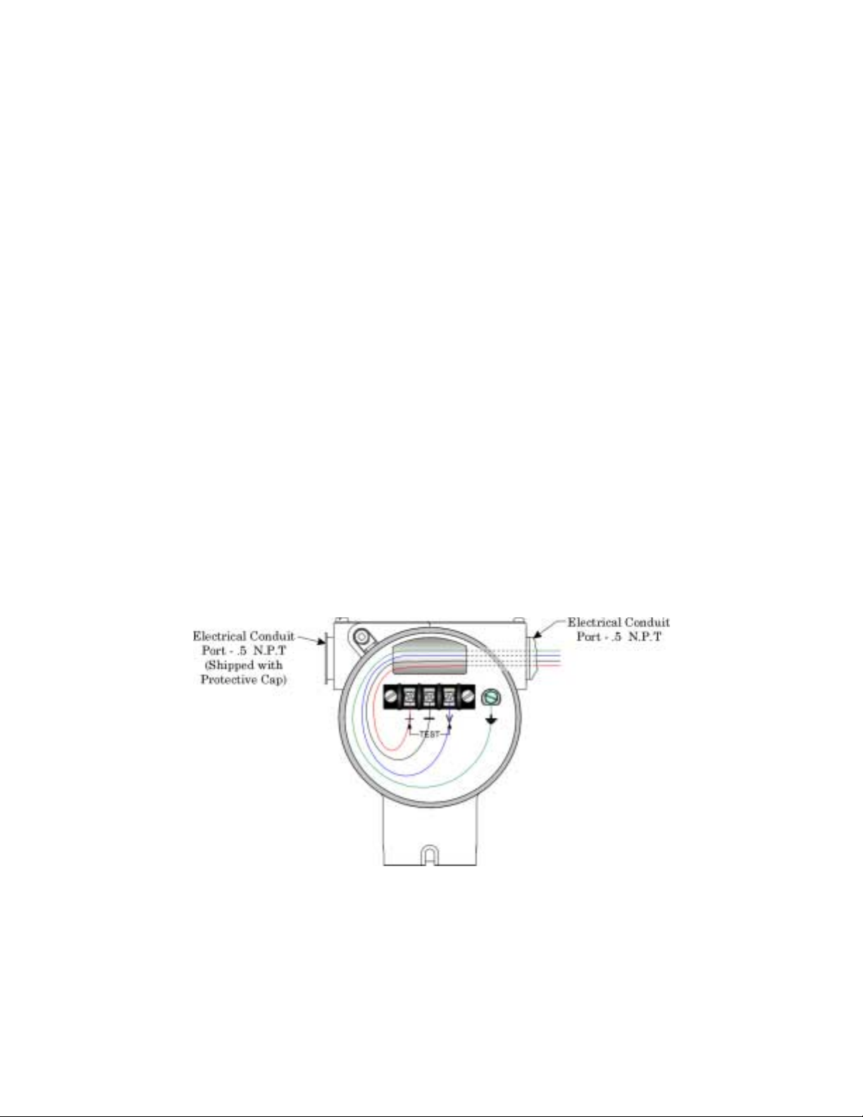
E Electrical Conduit Port. Two 1/2 inch NPT female ports are provided for electrical
conduit.
M-3601 Introduction / 1-1
Page 7
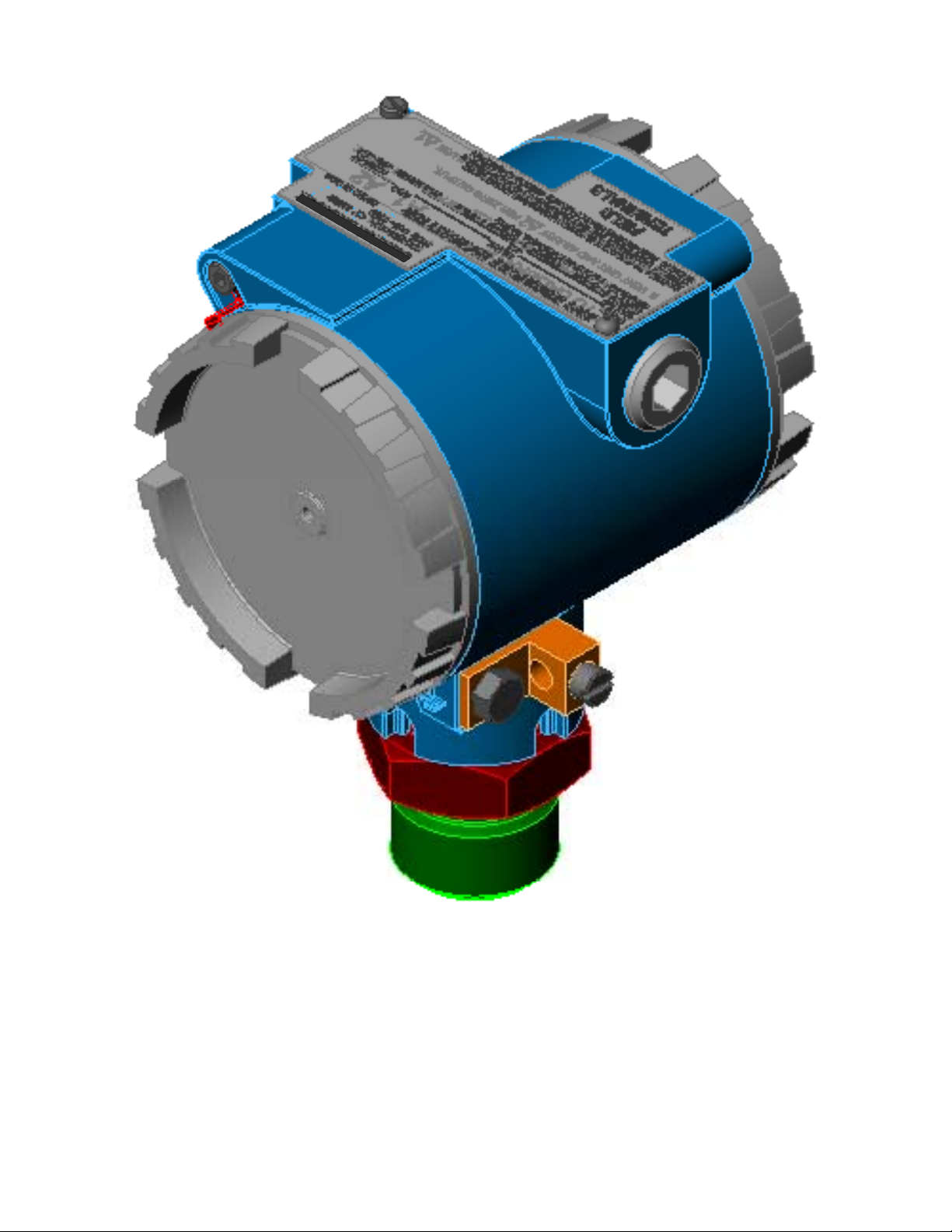
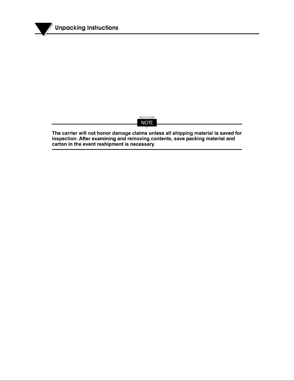
Figure 1-1 – PX726A Gauge Pressure Transmitter (with Internal Diaphragm)
1.3 MODELS APPROVED FOR HAZARDOUS AREAS
Transmitter mode l s ce rti fi e d fo r operation in h a za rdo us areas by Un de rwri ters Laborato ri e s
(UL) will have the appropriate logo inscribed on the instrument data plate. These models
are intended for use in t he following hazardous locations:
1-2 / Introduction M-3601
Page 8

Explosion-proof for Class I, Division 1, Groups C and D.
Nonincendive for Class I, Division 2, Groups A, B, C and D.
The National Electric Code, Article 500, defines the above classes and divisions as follows:
Class I Atmospheres: Contains flammable gases or vapors.
Class II Atmospheres: Contains combustible dust particles.
Class III Atmospheres: Contains ignitable fibers or flyings.
Division 1:
Where continuous expo su re, o r th reat o f fire o r ex plo sio n m ay b e presen t d u e to accid en t o r
uncommon occurrence.
Division 2:
Where threat of fire or explosion is not normally present, and not likely to result from
abnormal occurrence.
Groups A through D:
Cover various flammable gases an d liquids such as ethyl- ether vapor, gasoline, acetone,
etc.
Groups E through G:
Cover various combustible dusts such as dust fro m metalw o rk in g , co al, co k e carb o n b lack ,
grain, etc.
1.4 USING THIS MANUAL
Section 1A provides information relevant to product description, types of mounting,
measurement applications, service checks, and specificat ions.
Sections 2 through 5 describe installation, calibration, service and general specifications.
The Loop Powered Indicator option is covered in Appendix B.
M-3601 Introduction / 1-3
Page 9
Section 1A
GAUGE PRESSURE TRANSMITTERS
Series PX726A
1A.1 PRODUCT DESCRIPTION
Gauge Pressure Transmitters convert a pressure measurement into a proportional 4-20 mA
or a 1-5 Vdc outpu t si g n a l th a t ca n b e a ppl i e d to th e input of a co n tro l l er, recorder, i n di ca to r
or similar device. The Series PX726A, shown in Figure 1A-1, provides a standard 1-inch
flush diaphragm press ure connection.
Series PX726A Transmitters are offered in ranges from 0-100 inH
(max.). A listing of r anges for the Series PX726A is given in Table 1A-A.
Because of its compact size and light weight, the transmitter may be installed directly on a
process pipe. For installations that require other mounting arrangements, the transmitter
may be specified with a universal bracket. This bracket can be used to clamp the unit to a
two-inch pipe or secure it to a support structure.
O (max.) to 0-5000 psi
2
Figure 1A-1 - PX726A Gauge Pressure Transmitter (with Internal Diaphragm)
M-3601 GP Transmitters / 1A-1
Page 10
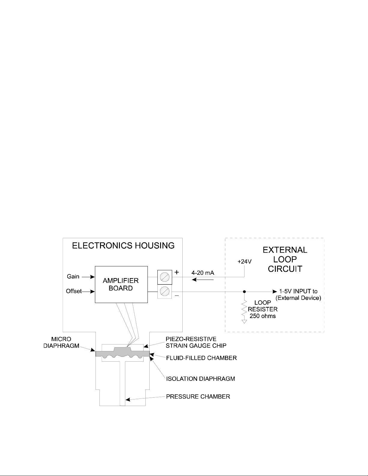
1A.2 THEORY OF OPERATION
The transmitter body is composed of an electronics housing and a sensor module assembly
as shown in the block diagram Figure 1A-2. The electronics housing contains the amplifier
circuitry and the field wiring terminals. The sensor module contains a pressure input
chamber, a fluid chamber, a recessed isolation diaphragm, and a micro diaphragm that
includes electronic sensing circuitry. (Transmitters with flush diaphragms omit the pressure
chamber and have the isolation diap hragm positioned at the very end of the sensor module.)
The input pressure applied to the pressure chamber is hydraulically transmitted through
the fill fluid contained by the isolation diaphragm. This pressure produces a strain on the
silicon diaphragm.
The micro diaphragm assembly contains four piezo-type, strain gauge resistors that are ionimplanted on the diaphragm's s urface and wired in a bridge configuration. The flexing of the
diaphragm causes changes of resistance in the bridge.
The bridge is powered by a constant current supply and produces a millivolt signal that corresponds to the me asured pressure. A circuit associ ated with the bri dge circuitry provides
measurement stability by compens ating for changes of ambient temperature.
The millivolt signal developed by the bridge is applied to a high-gain, linear amplifier and
converted to a tw o-wire, 4-20 m A current output. F igure 1A-2 sho ws this outpu t wired to a
typical external loop circuit that uses a 250-ohm load resistor and a 24 Vdc power source.
Figure 1A-2 - Simplified Diagram of GP Transmitters
1A-2 / GP Transmitters M-3601
Page 11

The 4-20 mA current flowing through the resistor provides a 1-5 Vdc input for the external
device.
The amplifie r circuit contains gain and o ffset adjustments for setting range calibration. A
jumper selects the damping op tion.
The unit may also be converted, at the users option, to a three-wire 1-5 Vdc output through
jumper selection.
1A.3 IDENTIFYING TRANSMITTER OPTIONS
A data plate affixed to the transmitter body lists the model number, serial number, and
instrument range. To identify the features and options furnished with your model, refer to
the complete model number contained in the sales order. This n umber includes a sequence
of suffix numbers that are identified in Tables 1A-A.
TABLE 1A-A - MODEL NUMBER BREAKDOWN FOR SERIES PX726A
PX726A - (1) – (2) ßßßß (see Codes below)
(1) INPUT RANGE (2) OPTIONS
CODE RANGE
CODE DESCRIPTION
100WCGI 0-17 to 0-100 inH
300WCGI 0-50 to 0-300 inH
400WCGI 0-67 to 0-400 inH
025GI 0-4 to 0-25 psi
050GI 0-8 to 0-50 psi
100GI 0-17 to 0-100 psi
300GI 0-50 to 0-300 psi
500GI 0-83 to 0-500 psi
1KGI 0-167 to 0-1000 psi
3KGI 0-500 to 0-3000 psi
2
2
2
MB Mounting bracket
O
M Local digital indicator
O
O
1A.4 TRANSMITTER MOUNTING
The transmitter may be mounted in any position. However, when it leaves the factory it is
calibrated for operation in the upright position with the electronics enclosure at the top and
the process connection at the bottom as shown in Figure 1A-1. If it is installed in a different
position, the transmitter may require a slight zero adjustment. This procedure is described
in Section 3 - Calibration.
The transmitter may be installed using connection-supported mounting or the optional
mounting bracket as follows:
Connection-Suppo rted Mounting. The tra nsmitter provides a m ale pressure connection
(1-inch NPT) which can also be used for mounting purposes (Figure 1A-4). This method of
mounting allows the transmitter to be connected directly to the pressure pipe or a pipe
fixture. If connection-supported mounting is not feasible, the optional mounting bracket
should be considered.
M-3601 GP Transmitters / 1A-3
Page 12
Optional Mounting Bracket. The brackets shown in Figure 1A-4 can be used when connection-supported mounting is not feasible or it is desired to mount the transmitter away
from the process. This bracket permits the transmitter to be clamped to a standard 2-inch
pipe with a single 2-1/4 inch u-bolt. The bracket may be positioned on the transmitter to
accommodate either a vert ical or horizontal running pipe.
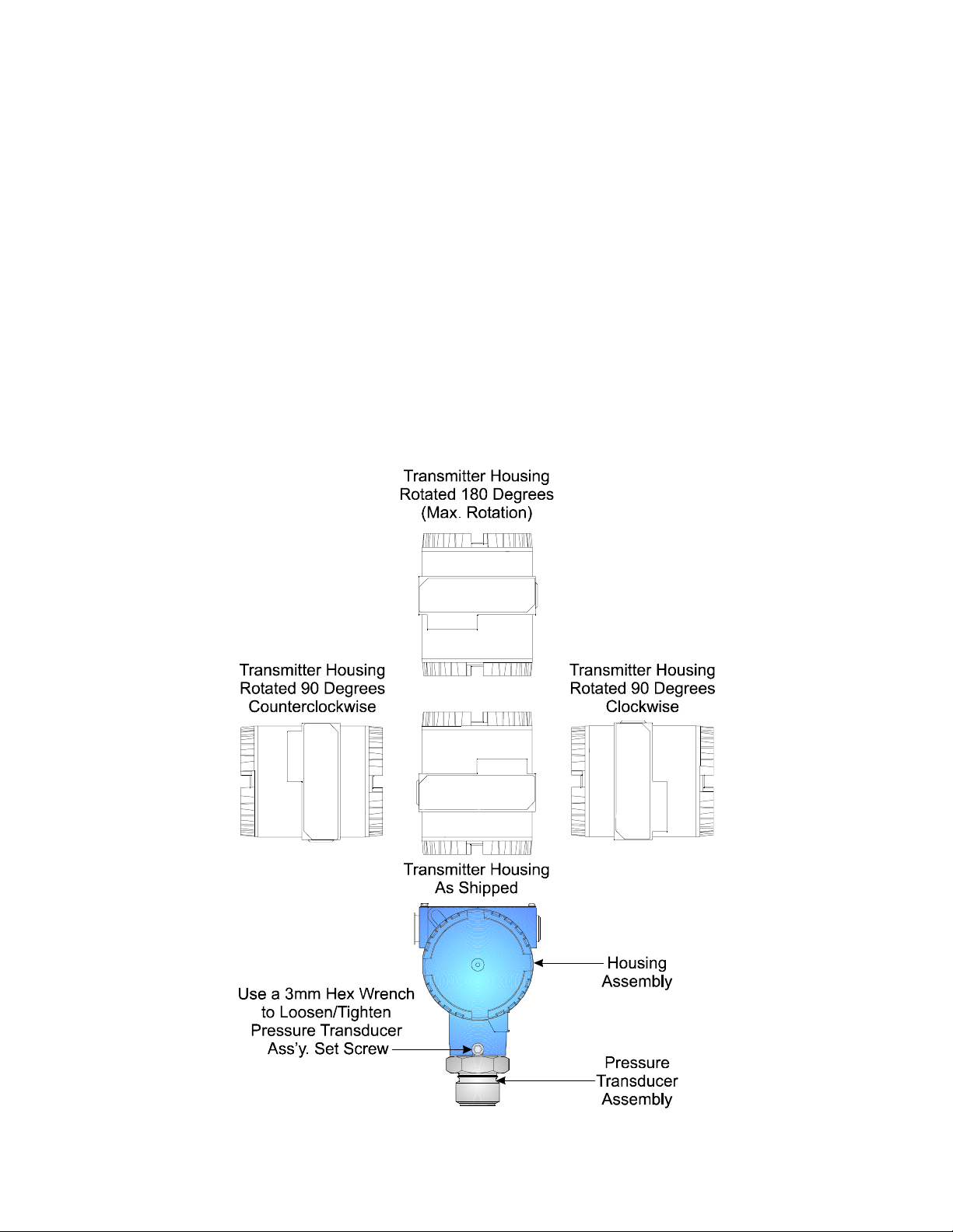
1A.4.1 Transmitter Housing Rotation
Once mounted, the Transmitter Housing can be rotated up to 180° in either direction, i.e.,
clockwise or counterclockwise. The Transmitter Housing must not be rotated from its
shipped position any more than 180° clockwise or counterclockwise. CAUTION: Trans-
mitter will be damaged if the Trans mitter Housing is rotated more than 180° from
its shipped position.
To rotate the T ransmitte r Housin g, the set scre w that lock s the Pressu re Tran sducer to the
Transmitter Housing must be removed with a 3mm Hex Wrench. Once the Transmitter
Housing has been turned to the desired position, be sure to replace and tighten the set
screw (see Figure 1A-3).
Figure 1A-3 -Transmitter Housing Rotation Diagram
1A-4 / GP Transmitters M-3601
Page 13
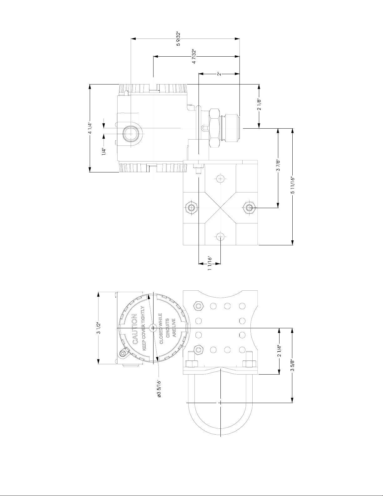
Figure 1A-4 - Overall Dimensions - Model PX726A
(With Neck Type Mounting Bracket)
M-3601 GP Transmitters / 1A-5
Page 14

1A.5 PRESSURE MEASUREMENT APPLICATIONS
The PX726A transmitter measures the pressure of a process medium flowing through a pipe
or contained in a tank. A discussion of some basic applications follows:
Figure 1A-5 - Process Pipe Mounting
Liquid Application. When measuring pressurized liquids in a process pipe, the
transmitter may be attached to the process line using a valve fixture as shown in Figure 1A-
5. However, if temperature or vibration characteristics at the site exceed the specified limits
of the transmitter, the transmitter should be placed in a more hospitable location with a
connection made through appropriate pressure tubing as shown in Figure 1A-6. Both
arrangements should include shutoff and drain valves to purge connection lines and the
transmitter.
Gas Application. The gas industry typically measures differential pressure, static pressure
and other variables associated with gas flow. A gas installation could use a GP Transmitter
to monitor the static pre ssure an d a DP T ransm itter to me asu re the di ffere ntia l pressu re as
shown below.
Figure 1A-7 sh ows the transmitters conn ected to a horizontal pipe. For these install ations
both transmitters are physically mounted above the connecting line to allow internal
moisture to drain away.
In Figure 1A-8, the gas flow is in a downward direction to minimize the accumulation of
moisture above the orifice plate. Otherwise, both transmitters are mounted and connected
in the same manner as described for horizontal pipes.
Figure 1A-6 - Pipe Tap Connection
Gas installations should include shutoffs and union fittings for both transmitters so that
they can be disconnected from the line without disrupting the process.
1A-6 / GP Transmitters M-3601
Page 15

Figure 1A-7 - Horizontal Gas Run
Figure 1A-8 - Vertical Gas Run
Steam Application. When measuring steam pressure, the maximum temperature of the
transmitter's electronic circuitry must be strictly observed. Temperatures above the
specified limit (see Environmental Temperature under topic 2.1) will cause output errors and
possibly result in dama ge to the transmitter. One method of prote cting the transmi tter can
be achieved by installing an extended, liquid-filled connecting line as shown in Figures 1A-9
and 1A-10. The liquid functions as a buffer and prevents live steam from entering the
transmitter.
When using liquid-filled system, the connecting line must be installed in a descending step
so that the transmitter is below the level of the process pipe tap and filling tee; this slope
will maintain the liquid in the connecting line and prevent it from being drawn into the
process pipe. Liquid-filled lines must also be properly filled and bled, and checked on a
regular basis.
A liquid-filled line is one way to isolate the transmitter from a steam process. As an
alternate method, a steam trap may be installed in the connecting line. Several
manufacturers offer traps for this application.
Figure 1A-9 - Horizontal Steam Pipe Figure 1A-10 - Vertical Steam Pipe
M-3601 GP Transmitters / 1A-7
Page 16
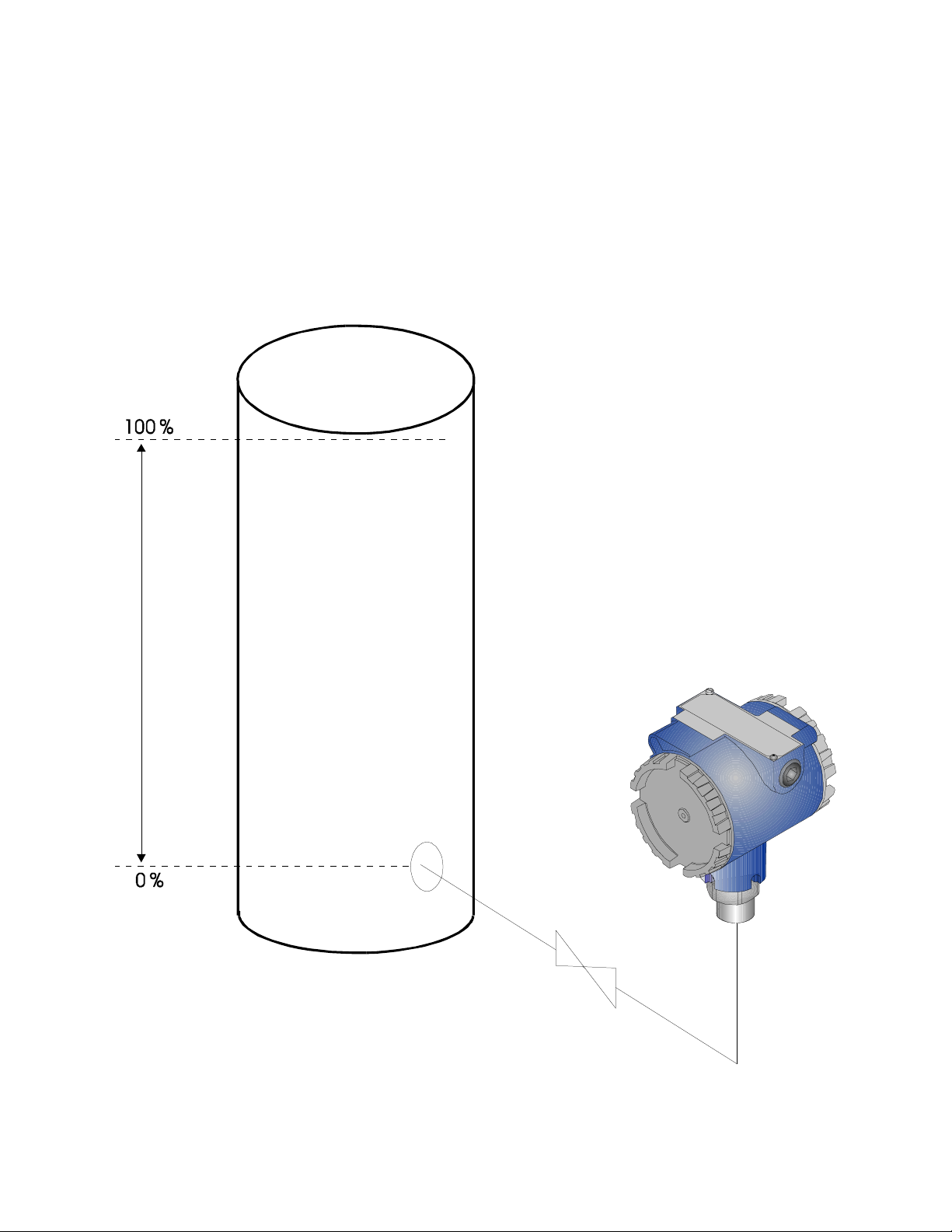
Liquid Level Application. GP Transmitters can be used to measure the head pressure of
a column of liquid in an open tank. For this application the transmitter is connected at the
bottom of the tank as shown in Figure 1A-11 (the transmitter co uld also be attached to the
tank through an appropr iate fitting).
The transmitter may be installed at, below, or above the 0% liquid level of the tank. If the
transmitter is exactly at the 0% level, it may be calibrated directly to the zero-base level. If
it is installed below or above the 0% level, a head error will occur. This error must added to
the measuring range during calibration otherwise the transmitter output reading will have
an offset error. Section 3 - Ca libration provides details for zero-based, elevated zero, and
suppressed zero calibration.
Figure 1A-11 - Liquid Leve l - Open Tank
1A-8 / GP Transmitters M-3601
Page 17

1A.6 SERVICE CHECKS
General troubleshooting hints are listed in Table 1A-B. Some of these checks will require a
digital multimeter (DMM). The DMM may be connected across the (+) and (V) terminals to
measure current directly without opening the current loop. See Section 4 Service for details.
TABLE 1A-B - TROUBLESHOOTING CHECKS
SYMPTOM RECOMMENDED CHECK
Low or no output:
Consistent Output Errors:
Fixed Output:
Erratic Output:
Check power supply for low dc output.
Check field wiring for shorts, opens, grounds or
excessive resistance.
Check that shutoff val ves are fully open.
Check for leaks in the connecting line or at
the transmitter connection.
Check for sediment or clogging in the connecting
line or at the transmitter connection.
Check for gas in liquid lines, or liquid in gas
lines.
Check zero and span adjustments using calibration
test setup.
Check that shutoff valves are fully open. Pressure
may be trapped in the connecting line.
Amplifier board may be defective.
Check loop wiring for shorts, opens, grounds or
intermittent connections.
Check piping for gas in liquid lines, or liquid in
gas lines.
Amplifier board may be defective.
1A.7 GP TRANSMITTER SPECIFICATIONS
Specifications that apply to the Series PX726A Transmitters are listed below. Those
specifications that are common to all PX726A transmitters are contained in Section 5
Specifications.
Maximum Input Ranges: 0-100 inH
details)
Overpressure Effect: +0.2% URL at maximum operating pressure
Wet End Materials: 316 SS
M-3601 GP Transmitters / 1A-9
O to 0-5000 psi (see Table 1A-C for
2
Page 18

Process Connections: 1 in. NPT male
Mounting Position Effect
on Transmitter Accuracy: ±2.0 inH
O which can be corrected by calibration
2
TABLE 1A-C - TRANSMITTER INPUT RANGES
Model
Suffix (1)
(Code)
100WCGI
300WCGI
400WCGI
025GI
050GI
100GI
300GI
500GI
1KGI
3KGI
See Table 1A-A for Series PX726A Model Number Codes.
0%
Minumum
Range
0-17 inH
0-50 inH
0-67 inH
2
2
2
0-4 psi
0-8 psi
0-17 psi
0-50 psi
0-83 psi
0-167 psi
0-500 psi
O
O
O
100%
Maximum
Range
0-100 inH
0-300 inH
0-400 inH
0-25 psi
0-50 psi
0-100 psi
0-300 psi
0-500 psi
0-1000 psi
0-3000 psi
O
2
O
2
O
2
Maximum
Working
Pressure
300 inH
900 inH
1200 inH
75 psi
150 psi
300 psi
900 psi
1500 psi
3000 psi
4500 psi
Offered
For Series
PX725A
O
2
O
2
O
2
Y
Y
Y
Y
Y
Y
Y
Y
Y
Y
1A-10 / GP Transmitters M-3601
Page 19

Section 2
INSTALLATION
2.1 INSTALLATION NOTES
Prior to installing the transmitter, factors such as environmental temperature, maintenance access, and transmitter construction materials will require consideration.
Environmental Temperature: The temperature operating ranges for the wet end and electronics assemblies of the transmitter are as follows:
1. Wet end w/ DC 200 fill: -40 to 220°F (-40 to 104°C)
2. Electronic - Amplifier Board -25 to 185°F (-32 to 85°C)
3. Electronic - Digital Indicator -22 to 158°F (-30 to 70°C)
When installing a transmitter, it is important to consider the temperature range of all
items listed above as each has different limits. For example, if item 1 were at the upper
limit of its range (220°F), item 2 would be 35°F over its limit of 185°F. Likewise, if the
same transmitter included a digital indicator, item 3, the indicator would be 62°F above its
158°F limit.
Under no circumstances should the internal temperature of the electronics housing be allowed to go above the upper limits specified above for items 2 and 3. Doing so will cause
output errors, and possibly result in damage to the electronic assemblies. Going below the
lower temperature limit can also lead to performance or failure problems. If temperature
extremes are anticipated, the transmitter should be installed in a more favorable environment or be provided with other means of protection.
Caution: The transmitter must always be operated within the temperature range of its wet
end and electronic assemblies. Prolonged operation under extreme conditions could result
in eventual transmitter damage.
Maintenance Access: Select a site that provides ease of access for maintenance and repairs.
Inspect the site for any potential hazards that could result in accidental damage to equipment or injury to persons. Clearly post any dangers that may not be apparent to operators.
Construction Materials : Prior to mounting the transmitter, check its construction materials
to insure that they are compatible with the process medium. Some gases or liquids will
react with certain metals and result in permanent damage to the transmitter. This type of
damage is not covered under the warranty agreement.
2.2 INSTALLATIONS IN HAZARDOUS AREAS
The information that follows only applies to transmitter models approved for use in
hazardous areas. Models without approval must never
M-3601 Installation / 2-1
be used for these installations.
Page 20
The installation of equipment in hazardous areas must comply with the National Electrical
Code ANSI/NFPA-70, and ANSI/ISA S82.01, S82.02, & S82.03 standards. Transmitters
certified for use in hazardous areas will have the mark of the certifying agency inscribed on
the transmitter data plate.
The checklist that follows emphasizes some key points of safety with regard to installations
in hazardous areas.
1. All transmitter wiring that passes through hazardous areas must be enclosed in metal
conduit. The point where the conduit connection feeds into the transmitter’s housing
must be properly secured to prevent entry of gases or other ignitable substances into
the transmitter. Explosion-proof wiring practices must be followed to prevent flashback
through the conduit.
2. The cover of the transmitter must be screwed in hand tight and fully seated. The cover
must be replaced if it is damaged or shows stripped threads.
3. The cover of the unit must always be in place and secured when the transmitter is
powered. The cover must never be loosened or removed unless the atmosphere is made
safe or all electrical power is removed from the transmitter.
WARNING: Removing the cover of a transmitter while it is operating in a hazardous area
is dangerous and could result in fire or explosion.
WARNING: EXPLOSION HAZARD
Do Not disconnect equipment unless power has been disconnected and the area
is known to be nonhazardous.
Figure 2-1 - Dressing of Wire Leads
2.3 ELECTRICAL WIRING NOTES
All wiring connections cited in the text and illustrations must conform to the National
Electrical Code, and local authority. Only technically qualified persons should perform
wiring procedures.
2-2 / Installation M-3601
Page 21

Conduit Connection: The transmitter provides a ½ inch NPT threaded female port for
electrical conduit. This port can mate with threaded conduit or an appropriate threaded
pipe adapter.
Note: The conduit connections must be secured with no less than five threads fully
engaged.
In some applications, condensation could form in the conduit, and seep into the transmitter
electronics housing. If allowed to continue, moisture build-up will degrade the transmitter
performance, and eventually cause damage. Installing the transmitter above the level of
the process connection can prevent this condition. Any moisture forming in the conduit will
then drain away by gravity.
Access to Wiring Terminals: Remove the threaded end cover to access the wiring terminals
(see Figure 3-2). If the cover cannot be loosened by hand, insert a flat metal bar or similar
tool between the cover protrusions and apply moderate counter-clockwise leverage. Before
re-installing the cover, make sure that the threads are clean. Tighten the cover by hand
until all threads are engaged, and the gasket is compressed.
Lead Dress: When feeding wire through the conduit opening of the transmitter, add about
six inches of slack for terminal connections. Dress the leads in a circular path around the
terminals as seen in Figure 2-1. The additional slack will make the connections more
manageable and prevent mechanical strain on the terminals.
2.4 WIRING OF 4-20mA SIGNAL/POWER LOOP
The 4-20mA signal/power loop can be powered in two ways. Figure 2-2 shows the loop
powered by the receiving device (controller, recorder, etc.), while Figure 2-3 shows the loop
powered by an external supply. In both instances, the 4-20mA current flows through a
250Ω load resistor and develops a corresponding 1-5V input for the receiving device.
Signal Shielding: Use twisted wire, shielded cable covered by insulating material for the
signal/power wiring. When properly grounded, this cable will minimize pickup of electromagnetic, and radio frequency interference.
The shield lead of the cable is typically grounded at the input of the receiving device
(computer controller, recorder, etc.) as shown in Figures 2-2 and 2-3. Never connect the
other end of this shield to the transmitter enclosure or attempt to ground the shield at
more than one point along the wire path. Multiple grounds will cause signal errors at the
input of the receiving device.
Although it is recommended to connect the cable’s shield to the power common return of
the receiving device, the actual connection point may differ depending on the design and
application of the device. In some instances, better noise immunity can be had by
connecting the cable shield to the chassis or a designated shield terminal on the device.
Check the instruction manual of the receiving device for the recommended connection
points.
M-3601 Installation / 2-3
Page 22

* The device may be an indicator, recorder, tone modulator, etc.
1
*
Connect the shield to earth ground or to a shield terminal on the device, if so equipped.
2
*
Refer to Figure 3-2 and set the Jumper Block for Current Operation.
Figure 2-2 - Transmitter Wired to Instrument Supply Source (4-20mA Circuit)
* The device may be an indicator, recorder, tone modulator, etc.
1
*
Connect the shield to earth ground or to a shield terminal on the device, if so equipped.
2
*
Refer to Figure 3-2 and set the Jumper Block for Current Operation.
Figure 2-3 - Transmitter Wired to External DC Supply (4-20mA Circuit)
2-4 / Installation M-3601
Page 23

* The device may be an indicator, recorder, tone modulator, etc.
1
*
Connect the shield to earth ground or to a shield terminal on the device, if so equipped.
2
*
Refer to Figure 3-2 and set the Jumper Block for Current Operation.
Figure 2-4 - Transmitter Wired to Instrument Supply Source (1-5V Circuit)
* The device may be an indicator, recorder, tone modulator, etc.
1
*
Connect the shield to earth ground or to a shield terminal on the device, if so equipped.
2
*
Refer to Figure 3-2 and set the Jumper Block for Current Operation.
Figure 2-5 - Transmitter Wired to External DC Supply (1-5V Circuit)
M-3601 Installation / 2-5
Page 24

2.5 WIRING OF 1-5V SIGNAL/POWER LOOP
The 1-5V signal/power loop can be powered in two ways, by the receiving device (controller,
recorder, etc.), or by an external supply. Provide a setup similar to that shown in either
Figure 2-4 or 2-5. Apply +24V across the + and - terminals of the transmitter as shown,
whether supplied by an external supply, or by the receiving device. Next, connect the 1-5V
output, or the terminal block labeled V to the input of the device. Notice: Unlike the
current loop, this input must be analog ground referenced, and not passed through a
sampling resistor.
Signal Shielding: Use twisted, three wire, shielded cable covered by insulating material for
the signal/power wiring. For further information regarding signal shielding, consult section
2.4.
2.6 EFFECTS OF LEAD & LOAD RESISTANCE & SUPPLY
VOLTAGE
The total loop resistance consists of the load (loop resistor) plus the resistance of both
conductors in the signal/power loop. For any given power supply voltage, the total loop
resistance must be kept within the specified limits. The graphs of Figures 2-6 and 2-7
illustrate the minimum and maximum loop resistance that may be used with various
supply voltages for models with and without digital indicators.
Figure 2-6 - Transmitter without Digital Indicator
2-6 / Installation M-3601
Page 25

Figure 2-7 - Transmitter with Digital Indicator
The graph of Figure 2-8 shows the cable length in feet vs. the cable resistance of both conductors for wire gauges between AWG 14 and AWG 22. For cable runs less than 1000 feet,
the resistance can be ignored.
Figure 2-8 - Cable Lead Length Vs. Total Lead Resistance
M-3601 Installation / 2-7
Page 26

Section 3
CALIBRATION
3.1 CALIBRATION SETUP
Equipment Required: Transmitter calibration requires a laboratory bench setup with the
following equipment:
1. Test source capable of generating fixed pressure values equivalent to 0%, and 100%
values of transmitter’s range (URL).
2. Pressure monitor device to read test source (±.025% accuracy)
3. Electrical supply source capable of producing 24V-DC power to the transmitter.
4. Digital Multimeter (DMM) w ith a 5- 1/ 2 digit s cale ( ±.005% accuracy)
5. Current Sam p li ng Res i s t or ( 250Ω9, ±.01%, 1/4W)
Lab Vs. On-Site Setup: Although it is more convenient and recommended to perform this
procedure using a laboratory setup, calibration can also be performed on site providing that
the connecting line or flange is equipped with a calibration tap and appropriate shutoff and
bypass valves. This added equipment allows you to feed in an external test pressure source
or use the process pressure as a reference signal. In the latter setup, the valves are closed
to seal a fixed pressure in the connecting line. Only fine calibration using the external
adjustments should be attempted in wet, dusty, or hazardous environments.
Before attempting on-site calibration, carefully check the application. If the transmitter is
operated in a closed control loop configuration, either the transmitter must be isolated
from the process, or the process must be turned off. If this is not done, a critical process
could accidentally be driven into a dangerous region causing damage to equipment and
property, and injury to persons.
Note: Before starting any test procedures, make sure that the transmitter is firmly
anchored in its intended operating position. A different mounting position can affect zero
calibration for some ranges and necessitate re-calibration.
Electrical Connections: The electrical connections for a voltage output calibration setup are
made to the transmitter as shown in Figure 3-1a. However, refer to Figure 3-1b if the
transmitter is configured for current mode operation. The Current Sampling Resistor will
convert the 4-20mA-output signal to a 1-5V signal, which generally allows for a more
accurate reading. A series milliammeter may also be used as discussed in Section 4.2.
3.2 ACCESS TO ADJUSTMENTS
The external adjustments are for fine offset and fine gain settings. The offset adjustment
screw will not affect the gain. That is, adjusting the offset (A1) screw will move both
calibration points equally. The gain adjustment will also affect the offset of the instrument.
That is, adjusting the gain (A2) screw moves the end point unequally. To minimize the
interaction of the gain, it is best to adjust the offset screw for full scale output while full
scale pressure is applied and adjust the gain screw for a zero output while minimum
pressure is applied.
M-3601 Calibration / 3-1
Page 27

To access the fine offset (A1) and fine gain (A2) adjustment screws, loosen the screw that
secures the I.D. Plate to the top of the transmitter housing and pivot the I.D. Plate. The
fine offset and gain screws are labeled A1 and A2 respectively. The calibration label that
identifies A1 and A2 is affixed to the top of the transmitter housing and will be exposed
when the I.D. Plate has been pivoted.
Removing the end cover accesses the transmitter’s coarse calibration adjustments. Once
the cover is removed, the adjustments appear as shown in Figure 3-2.
The PX726A Series Transmitter can be configured for either voltage, or current output. To
change the setting, simply change the position of the voltage/current jumper (JP1-JP8).
Note that the field wiring must also change if converting from voltage to current mode.
Figure 3-1a - Calibration Test Setup (Voltage Configuration)
Figure 3-1b - Calibration Test Setup (Current Configuration)
To activate the selectable damping option, the damping jumper (JP9) must be in place on
the board.
3-2 / Calibration M-3601
Page 28

Figure 3-2 - Calibration Adjustments
M-3601 Calibration / 3-3
Page 29

3.3 EXTERNAL CHECK PROCEDURE
The general check procedure determines the accuracy of the transmitter at its calibrated
operating range. It uses the offset (A1) and the gain (A2) adjustment screws for minor
calibration corrections. Proceed as follows:
1. Provide a test setup as shown in Figure 3-1a or 3-1b depending on whether the unit has
been configured for current or voltage mode. Make sure that no electrical power is applied to the transmitter while making connections. The Multimeter must be set in
“Voltage” mode.
2. Set the DMM to a scale that will cover a 1-5Vdc range.
3. Apply 24Vdc power to the transmitter.
4. Set the pressure test source for a precise 0% range value. The DMM should display
1.00Vdc ± 4mV (4mA dc ± 0.016mA).
5. Similarly, adjust the pressure test source f or 100% range value. The DMM should read
5.00Vdc ± 4mV (20mA dc ± 0.016mA).
6. If the readings of steps 4 to 6 are within tolerance, no calibration is required. Testing is
complete. However, if any readings were in error, proceed to step 7.
7. Set the test pressure source to 100%. If this reading is out of tolerance, correct it by
turning the A1 adjustment screw (clockwise rotation increases the reading).
8. Reset the test pressure source to 0%. If this reading is out of tolerance, correct it by
turning the A2 adjustment screw (clockwise rotation decreases the reading).
9. Recheck the 0%, and 100% readings . Repeat steps 7 and 8 as needed. This may need to
be done two or three times. If errors are still present at full-scale pressure, recheck the
switch settings. If the DIP Switch is in the correct configuration, proceed to step 10. If
errors are encountered at 0%, recheck the Rotary Switch settings. If the switch is in the
correct position, proceed to step 10.
10. If the above three readings cannot be brought into proper calibration, the transmitter
may require service or replacement. See Section 5, Service, for troubleshooting hints.
3.4 CALIBRATION ADJUSTMENTS
The range changing procedure uses the coarse span (SW1) and zero switches (S1:1-8),
along with the fine offset (A1), and gain (A2) adjustment screws. The locations of the
switches are shown in Figure 3-2. The equipment setup required to perform range
changing is the same as that described in topic 3.1. The coarse zero switches are contained
in a single DIP switch package, with the switches labeled from 1 to 8, with either a “1” or a
“0” silk-screened on the board. The coarse span switch is a 10 position rotary switch.
Coarse Span: The coarse span is set, by rotating the switch SW1, such that the desired
range of full scale is available. Span can be calculated using the formula below.
3-4 / Calibration M-3601
Page 30

Coarse Span URL Range = P
max
- P
min
------------ X 100%
URL
Once span has been calculated the desired switch position can be determined from Table 3A or Table 3-B.
Coarse Zero: Coarse zero adjustments are provided by switches S1:8-1. When these
switches are all set to ON, the maximum zero suppression (600%) is provided; when all are
set to OFF, the maximum zero elevation (600%) is provided.
The coarse zero is set for the region of full scale that the user desires to be the zero
reference. Consequently the possible zero positions are listed in %URL. This is not to be
confused with the %URL from the span. Unlike the span this does not represent an actual
range, instead it describes a pressure level that the user desires to set as a zero. The
following equation shows how to calculate the zero level in %URL:
Coarse Zero URL Range = P
min
------ X 100%
URL
Once the zero levels are calculated, the respective coarse zero switch positions can be
determined
from Table 3-A.
Fine Adjustments: At full-scale pressure adjust A1 so that the output is either 5V or 20mA.
Then, decrease the unit to zero pressure and adjust A2 so that the output is 1V or 4mA.
The adjustment of A1 should be such that the setting is barely 5V or 20mA (i.e. A small
rotation in the opposite direction should result in an immediate decrease in the output
voltage.). If this is not the case the screw may be over rotated. Repeat this procedure until
the output yields the appropriate values for high and low pressure. Once calibrated the
output stage is set and should need no further attention besides periodic tweaking.
3.5 TYPES OF RANGE CALIBRATION
When selecting a range, one of three types of calibration schemes will be encountered. Each
of these three methods refers to the manner in which a 0 psi input signal is referenced to
the 1-5V output of the transmitter. The three methods are defined as follows:
Zero Based Calibration:
0 psi = 1V (4mA) output
Sample Ranges:
0 to 50 psi
0 to 100 psi
Elevated Zero Calibration:
0 psi > 1V (4mA) output [0 psi results in an output greater than 1V (4mA)]
Sample Ranges:
-10 (vacuum) to +20 psi
-30 to 0 inHg
M-3601 Calibration / 3-5
Page 31

TABLE 3-A - COARSE ZERO SWITCH SETT INGS (El evation)
3-6 / Calibration M-3601
Page 32

TABLE 3-B - COARSE ZERO SWITCH S ETTINGS (Suppression)
M-3601 Calibration / 3-7
Page 33

Suppressed Zero Calibration:
0 psi < 1V (4-20mA) output [0 psi results in an output less than 1V (4mA)]
Sample Ranges:
1 to 10 psi
10 to 60 psi
50 to 100 psi
The above procedures are described in topics 3.6, 3.7, and 3.8. Select the procedure you
require.
3.6 ZERO-BASED CALIBRATION
This procedure describes the process by which the zero and span settings are obtained for
the 1-5V and 4-20mA output stages of the Series PX726A transmitters.
The following parameters relate directly to the calibration process:
URL: Upper Range Limit of sensing element. The URL is the maximum input
pressure that can be applied without over-pressuring the sensing
element.
Span: The algebraic difference between the limits of the range (P
max
– P
min
The desired span must always be less than or equal to the upper range
limit (URL) of the sensing element. Span is expressed as a percentage
of the upper range limit of the sensing element.
Zero: The point within the available pressure range the user defines as a zero
pressure reference.
P
: Maximum input pressure of a desired range, not necessarily the
max
maximum range of the sensing unit.
: Minimum input pressure of a desired range.
P
min
Theory of Operation: The output stage can potentially take a user defined portion of the 0-
100% URL pressure input, and display it as a corresponding 1-5V or 4-20mA output. The
range, desired by the user, is obtained by setting the appropriate coarse and fine zero and
span settings. Each coarse setting is described in Tables 3-A and 3-B, whereas the fine
settings are adjusted manually until the desired output is achieved. Fine adjustments are
made with two external adjustment screws. The output stage is designed to yield a Turn
Down of better than 6, while the fine adjustment screws should affect the output zero and
span by no more than 1.5%/Turn.
).
3.7 ELEVATED ZERO CALIBRATION
1. Calculate the total span required for the elevated zero range. For example, if the
desired elevated zero range is -10 to +30 psi, the total span will be 30-(-10) = 40 psi.
3-8 / Calibration M-3601
Page 34

2. Calculate the desired output reading for 0 psi. For this example, 0 ps i = 25% of the span
from -10 to 30 psi. The output should therefore be 25% of the way from 1-5V, or
2V(8mA). Set the Dip and Rotary switches in accordance with Table 3-A. Elevated zero
values are expressed as positive percentages of calibrated span. Zero percent represents
zero elevation. If the desired percent elevation is in between values listed in the table,
try the next closest setting.
3. Apply a 100% pressure input to the transmitter equivalent to the upper range value
(URV). For this example, U RV = 30 p s i .
4. If transmitter output is not 5. 000V (20.00mA), adjust A1 to make a minor correction.
5. Vent the input pressure. Adjust A2 to set the output to the 0 psi reading calculated
above.
6. Recheck the transmitter output with the input press ure vented, and 100% inputs. The
DMM should provide respective readings of the output calculated above, and 5V (20mA)
(± 0.15% full scale).
7. If necessary, repeat the A1 and A2 adjustment procedures.
8. If problems persist, recheck the DIP switch settings. Try setting the switches to the
lower percentage. For instance, if the desired percent elevation is 15%, set the switches
for an elevation of 10%.
3.7.1 Zero Elevation Example (see Table 3-A)
A DP Sensor is mounted across an orifice plate to measure gas flow. Full-scale differential
pressure is 40” H
O in either direction (±40” H2O). The span is +40” - (-40”) = 80” H2O. If a
2
100” Transmitter is used, the Coarse Span Rotary Switch (SW1) setting is found by
dividing the span (80” H
O) by the Transmitter’s range; in this case 100” H2O, i.e., 80/100 =
2
80%. Therefore, the SW1 should be set to position 2 (64% - 84%).
Set the elevation to 50% of the calibrated range (00100010). This will set up the 2808 for
calibration of 1.000V (4.00mA) at -40” and 5.000V (20.00mA) at +40”. At 0 psid the output
will be ½ scale, i.e., 3V (12mA). Apply +40” H
O to the High Side of the Transmitter and
2
use Fine Adjustment Screw A1 to set the output to 5.000V (20.00mA). Vent the unit and
use Fine Adjustment Screw A2 to adjust the Transmitter’s output to 3V (12mA). Apply
+40” H
O to the Low Side of the Transmitter and observe the output. Maximum error is
2
the deviation from 1.000V (4.00mA).
Note: Transmitter factory calib ration and compensation is for positive DP pres-
sure only. Negative pressure indication is possible with the abovedescribed method of reduced accuracy. Full-scale negative indication cannot be achieved unless the DP range is at least 2 times the negative range.
3.8 SUPPRESSED ZERO CALIBRATION
1. Calculate the total span required for the suppressed zero range. For example, if the
desired suppressed zero range is +15 to +80 psi, the total span will be: 80 - 15 = 65 psi.
M-3601 Calibration / 3-9
Page 35

2. Set the Dip and Rotary switches in accordance with Table 3-B. Suppressed zero values
are expressed as negative percentages of upper range limit (URL). Zero percent URL
represents no suppression. If the desired percent suppression is in between values, try
the next closest setting.
3. Apply a 100% pressure input to the transmitter equivalent to the upper range value
(URV). For this example, U RV = 80 p s i .
4. If transmitter output is not 5. 000V (20.00mA), adjust A1 to make a minor correction.
5. Lower the input pressure to P
. Adjust A2 to set the output to 1.000V (4.00mA).
min
6. Recheck the transmitter output with 0%, and 100% inputs. The DMM should provide
respective readings of 1.000V (4.00mA), and 5.000V (20.00mA) (± 0.15% full scale).
7. If necessary, repeat the A1 and A2 adjustment procedures.
8. If problems persist, recheck the DIP switch settings. Try setting the switches to the
lower percentage. For instance, if the desired percent suppression is -85%, set the
switches for a suppression of -90%.
Figure 3-3 - Water Tower Level Measurement - Zero Suppression
3-10 / Calibration M-3601
Page 36

3.8.1 Zero Suppression Example (see Figure 3-3 & Ta bl e 3-B)
The full water tower of Figure 3-3, produces 53.5 psi of pressure due to the 125 foot head,
i.e 10.7 psi plus 42.8 psi. To determine the Coarse Span Rotary Switch (SW1) setting,
divide the pressure produced by the 25 feet of water in the tank by the Transmitter’s
range; in this case 50 psi, i.e., 10.7/50 = 21.4%. Theref ore, the SW1 should be set to position
8 (18.5% - 23%).
To determine the zero suppression necessary for this example, divide the pressure
produced by 100 feet of water (height of tower to bottom of tank) by the Transmitter’s
range; in this case 50 psi, i.e., 42.8/50 = 85.6%. With the Coarse Span Rotary Switch SW1
set to its SW1-8 position, set the value of the Coarse Zero Switch (S1) to either -80%
(00001100) or -90% (00001010), or to a binary value between the two e.g., 00001011 ( - 85% ) .
Use Fine Adjustment Screw A2 to set 1.000V (4.00mA) @ 42.8 psi and use Fine Adjustment
Screw A1 to set 5.000V (20.00mA) @ 53.5 psi.
Note: When Zero Suppression is used, the maximum applied pressure may be up
to 125% of the URL.
3.9 SELECTABLE DAMPING
The damping feature provides compensation for applications with severe pressure
pulsation that cause the DC output of the transmitter to seem unstable. Controlling the
response time of the transmitter output can minimize this condition. Do not use damping
when the application requires dynamic pressure measurement.
Jumper JP9 can be set to apply damping to the output. With jumper JP9 in place, the
damping is on. If the jumper does not connect the two pins together, the damping is off.
M-3601 Calibration / 3-11
Page 37

Section 4
SERVICE
4.1 GENERAL
Servicing should only be performed by technically competent persons skilled in the use of
pneumatic and electronic test equipment and having knowledge of troubleshooting
procedures.
After any service procedures are completed, the transmitter cover must be installed and
properly tightened. A failure to secure the cover will result in a loss of the enclosure's dusttight, water-tight seal and explosion-proof rating.
Warning
No attempt should be made to service a transmitter while it is powered and
operating in a flammable or ex plosive environment. Either the area must be
made safe or the transmitter must be powered down, disco nnected, and taken
to a safe, non-hazardous area.
4.2 TROUBLESHOOTING
Some troubleshooting procedures will require that you use a digital multimeter (DMM) to
measure the loop current. Connect the DMM across the V and (+) terminals of the
transmitter as shown in Figure 4-1 and set it to its "milliampere" function. This method of
connection will not disturb the signal/power loop. The DMM reading will be proportional to
the input pressure and cover a range of 4-20 mA.
4.3 FACTORY REPAIRS
If you determine that a fa ult is pre sent i n the tra nsmitte r's PC b oard or pre ssure sen sor, do
not attempt any service as specialized factory equipment and test procedures will be
required. Defective transmitters may be returned to OMEGA for evaluation or repairs.
Transmitters in warranty will be repaired or replaced per the warranty agreement
contained at the end of this manual.
M-3601 Service / 4-1
Page 38

Figure 4-1 - Using Internal TEST Terminals to Measure Current
4-2 / Service M-3601
Page 39

Section 5
SPECIFICATIONS
NOTE: The specifications listed here are common to Series PX726A Transmitters
described in this manual.
5.1 FUNCTIONAL SPECIFICATIONS
Current Loop Mode:
Supply Voltage 24.0 Vdc nominal
7.00 Vdc min. at transm itter
10.0 Vdc min. with digital indicator option
37.0 Vdc max. at transmitter
42.0 Vdc with external load specified
Reverse polarity protection provided
Output 4-20 mA dc output, two wire analog (ISA 50.1
Type, Class U2)
Current limited to 28 mA max.
Minimum current is 2 to 3.5 mA.
Voltage Mode:
Supply Voltage 6-42 Vdc
Reverse polarity protected to 90 Vdc
Supply Current 1.6 mA nominal
Output 1-5 Vdc (3-wire)
Calibration Adjustments: Span Adjustment:
Adj. Range is 16 to 100% URL.
Coarse Span set by Rotary s w itch package.
Fine Span set via 25-turn pot .
Zero Adjustment:
Adj. range is -600 to 600% LRL for elevation
and suppression.
Coarse Zero provided by DIP switch
selections. Fine Zero set via 25- turn pot.
Response Time & Damping: Time Constant:
(Time required for 63% change in output
with a 100% input change)
Damping OFF ≅ 0.16 ms
Damping ON = 50 ms +20%
Damping:
User selectable by jumper circuit
M-3601 Specifications / 5-1
Page 40

Recovery:
Time to steady output after application of
24 volt supply with constant pressure is 5
ms maximum (With No Damping)
Linearity: On low-range models, full vacuu m can represent
an appreciable percentage of URL. If, on those
models, calibration contains 50% of zero
elevation, non-linearity errors can be as high as
+1%.
5.2 PERFORMANCE SPECIFICATIONS
Accuracy: (Includes independent linearity, hysteresis and
repeatability)
+0.1% of calibrated span
Resolution: Virtually infinite
Long Term Stability: At constant conditions. +0.25% of URL/6 mo.
Ambient Temperature Effect: Total including Zero & Span
+0.010% of URL per °F fr om -25 to 75 °F
+0.015% of URL per °F fr om 75 to 185 °F
+0.020% of URL per °F on 100 inH2O only
Power Supply Effect: + .005 %/Vdc
Ripple and Noise: In accordance with ISA 50.1, Section 4.6
5.3 ENVIRONMENTAL SPECIFICATIONS
Temperature Limits: Wet End using DC 200 Fill:
-40 to 220 °F (-40 to 104 °C)*
Amplifier:
-25 to 185 °F (-32 to 85 °C)
Digital Indicator:
-22 to 158 °F (-30 to 70 °C)
Storage:
-40 to 212 °F (-40 to 100 °C)
* The maximum permissible temperature inside
the enclosure (irrespective of sensor temperature)
is 185 °F (85 °C) for the amplifier board, and 158
°F (70 °C) for the digital indicator option.
5-2 / Specifications M-3601
Page 41

Humidity Limits: Specified with transmitter electronic
housing cover installed.
o
15-95% RH to 140 °
F (60 °C)
15-50% RH to 185 °F (85 °C)
EMI Effect: +1% of URL @ 10 V/M, 20 MHz to 500 MHz
Meets /SAMA PMC-33-1C with transmitter
cover in place and all wiring contained in
grounded conduit.
Surge Protection: Bipolar, differential surge
1000 watts for 1 ms (without digital
indicator option)
May be used with purchased surge protector
for additional protection (for non-hazardous,
non-approved installati ons only).
Vibration Effect: Less than +0.1% of URL for 10 to 500 Hz at
1 g on any axis. Meets SAMA PMC-31-1
5.4 PHYSICAL SPECIFICATIONS
Fill Media: DC 200 Silicone
Electronics Housing: Low copper alum inum, epoxy fin ish, NEMA
4X rating
Electrical Connections: 1/2 NPT conduit connection with internal
field wiring terminals.
M-3601 Specifications / 5-3
Page 42

Series PX726A Transmitter
Special Instructions for Class I, Division 2 Hazardous Locations
1. The OMEGA Series PX726A Gauge Pressure Transmitter is listed by Underwriters
Laboratories (UL) as nonincendive and are suitable for use in Class I, Division 2,
Groups A, B, C and D hazardous locations or non-hazardous locations. Read this
document carefully before installing a nonincendive OMEGA Series PX726A Pressure
Transmitter. In the event of a conflict between the Series PX726A Instruction Manual
(M-3601) and this document, always follow the instructions in this document.
2. Wiring must be performed in accordance with Class I, Division 2 wiring methods as
defined in Article 501-4 (b) of the National Electrical Code, NFPA 70 for installations
within the United States, or as specified in Section 18-152 of the Canadian Electrical
Code for installation in Canada.
3. Model equipped with the Loop Powered Indicator Option (Appendix B) are approved for
use in Class I, Division 2, Groups A, B, C and D hazardous locations.
4. WARNING: EXPLOSION HAZARD - Substitution of components may impair
suitability for use in Class I, Division 2 environments.
5. WARNING: EXPLOSION HAZARD - When situated in a hazardous location,
turn off power before servicing/replacing the unit and before installing or
removing I/O wiring.
6. WARNING: EXPLOSION HAZARD - Do Not disconnect equipment unless the
power has been switched off or the area is known to be nonhazardous.
05/08/2001 Appendix A of M-3601 Page 1 of 1
Page 43

Appendix B
R
R
R
R
R
R
R
R
R
LOOP POWERED INDICATOR OPTION
For
For
Series PX726A
Series PX726A
Industrial Pressure Transmitters
Industrial Pressure Transmitters
1
TB2
R
R
R
R
R
R
R
M
An OMEGA Technologies CompanyAn OMEGA Technologies Company
E
PSI
R
Operator's Manual
Operator's Manual
M-3601/1101 - Appendix B
M-3601/1101 - Appendix B
Page 44

Appendix B
LOOP POWERED INDICATOR OPTION
TABLE OF CONTENTS
SECTION TITLE
Section 1 - INTRODUCTION
1.1 INTRODUCTION .............................................................................................................. 1
1.1.1 Features............................................................................................................................... 1
1.1.2 Hardware Circuit Overview................................................................................................ 1
1.1.3 Adjustments ........................................................................................................................ 2
1.1.4 Connectors .......................................................................................................................... 2
Section 2 - INSTALLATION, OPERATION & SERVICE
2.1 INSTALLATION & REMOVAL/REPLACEMENT OF THE LPI................................... 3
2.1.1 Installation/Removal of the Loop Powered Indicator......................................................... 3
2.2 FIELD WIRING .................................................................................................................7
2.3 OPERATIONAL DETAILS............................................................................................... 7
2.3.1 Configuring the Loop Powered Indicator........................................................................... 7
2.3.2 Accuracy and Decimal Point Settings .............................................................................. 10
2.3.3 Displaying Current Using the LPI ....................................................................................10
2.3.4 Error Conditions ............................................................................................................... 11
2.3.4.1 Conversion and Display Error Conditions........................................................................ 11
2.4 SERVICE.......................................................................................................................... 11
Section 3 - SPECIFICATIONS
3.1 ENVIRONMENTAL SPECIFICATIONS ....................................................................... 12
M3601/1101 Appendix B Page 0-1 Table Of Contents
Page 45

Section 1
INTRODUCTION
1.1 INTRODUCTION
The loop powered indicator (LPI) option is used to provide local indication in engineering
units of the measurand represented by a 4-20 mA current loop. The LPI may be installed in
a Series PX725A, PX726A or PX771A Transmitter with the Display Cover Assembly or in a
stand-alone housing. The LPI is powered by the 4-20 mA current loop using less than 500
uA @ 3 V for the electronic circuitry.
The LPI option is a circuit board assembly with a micro-controller, a liquid-crystal display
(LCD) and active electronic circuitry contained on a single board, i.e., the “Meter/Display
Board.” The Meter/Display Board plugs into the “Meter Motherboard” that provides the
electrical connections from the transmitter interface and allows the display to be rotated in
90-degree increments.
1.1.1 Features
• Powered by a 4-20 mA current loop using less than 500 uA @ 3V
• Dual Board Set - Meter Motherboard allows the Meter/Display Board to be rotated in
90-degree increments.
• 4½ Digit Display allows display of numeric values as large as 19999.
• Eight selectable unit labels: mA, %, psi, IN H2O, bar, kg/cm2, °C, and °F.
• One selectable “no-label” position.
• Reverse polarity protection.
• Over current protection
1.1.2 Hardware Circuit Overview
The LPI option uses a micro-controller with integral LCD display drivers. The current
flowing through the LPI is sampled and converted to a corresponding digital word. Based
on user-configuration the digital value is displayed in engineering units along with a unit
label.
The 4½ digit display can show numeric values as large as 19999. The display contains eight
integral unit labels. These are: mA, %, psi, IN H2O, bar, kg/cm2, °C, and °F.
Calibration is done at the board level by injecting known current levels into the assembly,
reading the current and computing correction coefficients that are then stored in the LPI.
The coefficients are then used in a correction algorithm to linearize the current signal and
achieve a minimum accuracy of 0.1%FS at room temperature. The circuit uses precision
resistors to sample the current. The Meter/Display Board is burned-in for long-term
stability and reliability. Operating temperature is limited by the LCD display to -30 to +70
°C. Calibration is done once at the factory, but unit display selection may be done as often
as required by the user (see Section 2.3.1).
Reverse polarity protection is achieved by shunting the entire circuit with a diode. A 250
mA fuse provides overcurrent protection. A shunt capacitor is also included to minimize
EMI effects and provide secondary transient protec tion.
Appendix B Page 1 Loop Powered Indicator
Page 46

The two-board assembly is designed for field retrofit in Series PX725A, PX726A and
PX771A pressure transmitters.
1.1.3. Adjustment s
Adjustment potentiometers are unnecessary in the LPI. The indicator is always scaled to 420mA. The user configures the LPI in engineering units of their choice, i.e., mA, %, psi, IN
H2O, bar, kg/cm2, °C, ° F or Cus t om.
1.1.4 Connectors
The LPI Assembly comes in two parts: The Meter Motherboard and the Meter/Display
Board. The Meter Motherboard is assembled into the Series PX725A, PX726A or PX771A
Transmitter by connecting the transmitter’s terminal block to the spade fingers integral to
the Meter Motherboard and installing the mounting screws through the Meter
Motherboard to the cast-in mounting bosses in the transmitter housing. The customer cable
is then connected to the compression-type terminals of Terminal Block TB1 on the Meter
Motherboard. Finally, the Meter/Display Board plugs into the Meter Motherboard in any
one of four positions depending on the desired meter rotation; this is through a set of twoconductor “Berg” connectors. The Meter/Display Board is also secured to the Meter
Motherboard with four screws.
Figure 1-1 - PX725A, PX72 6A or PX771A Transmitter
with Loop Powered Indicator
Loop Powered Indicator Page 2 Appendix B
Page 47

Section 2
INSTALLATION, OPERATION & SERVICE
2.1 INSTALLATION & REMOVAL/REPLACEMENT OF THE LPI
2.1.1 Installation/Removal of the Loop Powered Indicator
The following parts are provided for field installation of the Loop Powered Indicator option:
One (1) - O-Ring, Size - 149
Two (2) - S tandoffs, #4 M/F Sh oulder
Two (2) - Standoffs, 4-40 x .750 M/F
One (1) - Meter Motherboard Ass’y.
One (1) - Meter/Display Board Ass’y.
Two (2) - Standoffs, 4-40 x .375 M/F
Four (4) -Screws, 4-40 x ¼ Pan Head
One (1) - 2808 Display Cover Ass’y.
WARNING
Never attempt to service a Series PX725A, PX726A or
PX771A Transmitter while it is operating in a hazardous
environment. Either the area must be made safe or the
unit must be unwired, unmounted, and taken to a safe,
non-hazardous area.
WARNING
Never attempt to install or remove any components (PCBs
or Field Wiring.) while the unit is running. Doing so can
cause sudden electrical transients or imbalances that
are capable of causing damage to the module or
component in question, as well as other associated
circuit boards. Always turn off ANY Transmitter to
Instrument circuits (at the instrument or External DC
Power Source) before changing or adding any components.
CAUTION
Place any related critical processes under manual or
auxiliary control prior to shutting down or performing
any of the steps discussed herein.
To install the Loop Powered Indicator (LPI) option into a Series PX725A, PX726A or
PX771A Transmitter, follow steps 1 through 9 below. To remove the LPI see step 10. Note:
The LPI is loop powered and may only be used with Transmitters configured in the “420mA” mode.
1. Remove the appropriate Cover Assembly from the instrument (see Figure 2-1). The
Cover Assembly is factory installed “hand tight,” i.e., there is no torque required.
Appendix B Page 3 Loop Powered Indicator
Page 48

2. Referring to Figure 2-2, install the two (2) 4-40 x .759 Standoffs into the Transmitter
at location A.
Figure 2-1 - Transmitter Cover Assembly Removal
3. Referring to Figure 2-2, install the two (2) 4-40 x .375 Standoffs into the Transmitter at
location B.
4. Disconnect the Field Wires (if installed) from the Transmitter’s Terminal Block.
5. Remove the three (3) Field Wiring Screws/Clamps from the Transmitter’s Terminal
Block.
6. Secure the Meter Motherboard to the Transmitter via the three (3) Field Wiring
Screws/Clamps removed in step 5. Using two (2) #4 M/F Shoulder Standoffs, secure the
Motherboard to the Standoffs installed in step 3.
7. Install the Meter/Display Board onto the Meter Motherboard after aligning the appropriate Meter/Display Board Interface Connector (P1 through P4) with J1 of the
Meter Motherboard. Secure the Meter/Display Board to the four standoffs (Locations A
& D of Figure 2-2) via four (4) 4-40 x ¼ Pan Head Screws.
Loop Powered Indicator Page 4 Appendix B
Page 49

Figure 2-2 - Loop Powered Indicator Installation Diagram
Appendix B Page 5 Loop Powered Indicator
Page 50

8. Connect the field wires to the compression-type terminals of Meter Motherboard
Terminal Block TB1 (see Section 2.2 & Figure 2-5). Configure the LPI for operation
(see Section 2.3.1).
9. Install the Transmitter Display Cover Assembly (with size 149 O-Ring) onto the
Transmitter (see Figures 2-3 & 2-4). Lubricate O-Ring with Dow Corning Silicone
Grease (Compound 4) or equivalent prior to assembly. Lubricate threads with
“NEVER-SEEZ” “Pure Nickel Special” or equivalent prior to assembly. Tighten until
Cover contacts the Transmitter Hou sing (no torque required).
Figure 2-3 – Series PX725A, PX 726A & PX771A Display Cover Assembly
Figure 2-4 - Transmitter with Loop Powered Indicator Option Installed
Loop Powered Indicator Page 6 Appendix B
Page 51

10. To remove the LPI Option from a Series PX725A, PX726A or PX771A Transmitter,
follow steps 7 through 9 in reverse order, removing rather than installing the item in
question.
2.2 FIELD WIRING
The LPI uses compression-type terminals that accommodate up to #14 AWG wire. A
connection is made by inserting the bared end (1/4 inch Max.) into the Meter Motherboard
Connector (TB1) clamp beneath the screw and then securing the screw. Insert the bared
end fully to prevent short circuits.
Allow some slack in the wires when making terminal connections. The slack makes the
connections more manageable and minimizes mechanical strain on the Meter Motherboard
and the wiring harness (see Section 2.4 of M3600, M3601, M3602 and Figure 2-5 below).
Figure 2-5 - Transmitter LPI Option Field Wiring
2.3 OPERATIONAL DETAILS
2.3.1 Configuring the Loop P o wer ed Indicator
Configuration involves selecting an engineering unit (called the Base Unit or BU) and then
establishing Zero and Full-scale values to be used when converting current into that unit.
The Mode (left-hand) and Select (right-hand) buttons are used to configure the LPI. The
LPI ships from the factory with a configuration that displays the flowing current in a BU of
percent (%). During configuration the Mode button is used to move through the
configuration sequence and the Select button is used to choose a particular setting from
those available at a particular point in the sequence.
Configuration begins with the selection of an engineering-unit followed by the choices for
the zero; minus sign, ten-thousandths half-digit, four full digits (thousands to units), then
the decimal point. Next is the Full-scale; minus sign, ten-thousandths half-digit,
Appendix B Page 7 Loop Powered Indicator
Page 52

thousandths to units, and decimal point. The final press of the Mode button causes an exit
from configuration mode to run mode. At any point in the sequence pressing the Mode
button selects the next item in the order i.e., to leave a previously configured item as is,
press Mode to skip over it. When configuration is started a one-minute timer is loaded; it is
reloaded whenever a Mode or Select button is pressed. If no button activity occurs for one
minute the timer will expire and restore the previously active configuration.
Figure 2-6 - Loop Powered Indicator - Mode (SW1) and Select (SW2) Buttons
During configuration any previously configured engineering unit, minus sign, tenthousandths digit and decimal point are ignored; the user MUST select them if they are to
be active in the new configuration. Configuration proceeds as follows:
1. Press and hold the Mode (left-hand) button until one of the unit labels begins blinking;
this typically takes 5 seconds. The display will be all blank except for a small lowercase letter ‘u’ located in the upper half of the rightmost digit. The label of the
previously configured engineering unit will be blinking. Remember that the previous
engineering unit label is only blinking as a convenient starting point - in order to
remain in effect it must be selected again unless another unit will be chosen. If the
previously configured BU was ‘Custom,’ the ‘u’ will be blinking.
2. Press the Mode button to change the displayed blinking engineering-unit label, then
press Select to make the selected unit active and move to minus sign selection. A unit
selection MUST be made otherwise repeated Mode presses will only cycle through the
unit selections. If the integral unit labels do not match the application unit, press the
Mode button until the small letter ‘u’ is blinking. This is the Custom unit selection,
meaning that the display will not show a unit label. In this case an external label
should be us ed . A Cu st om un it m i ght b e us ed wh er e th e re a di ng w ill be in f eet of w at er
or millimeters of mercury, or Pascals. Once a unit is selected the display changes.
Loop Powered Indicator Page 8 Appendix B
Page 53

If the selected unit is mA or % no further configuration is allowed and configuration
mode ends. For other units the following occurs.
The SET LO legend appears with the minus sign blinking, and the previously configured digits for the Zero appear without a decimal point. Previously configured minus
sign and ten-thousandths half-digit choices are cancelled, and new selections must be
made. Press Select to make the minus active, press Mode to skip over it. The tenthousandths digit (a one) begins blinking after the minus sign has been configured.
Again, press Select to make it active, press Mode to skip over it.
After the ten-thousandths digit is selected the thousands (leftmost) full digit will begin
blinking.
3. Press the Select button to increment the digit (zero to nine) or press Mode to leave the
digit as it is and activate the next digit location to the right. Repeat until all digits
have been set.
When Mode is pressed while the units (rightmost) digit location is blinking decimal
point locations 2 and 5 will start blinking. As with units, a selection MUST be made or
the Mode button will just cycle through all decimal point choices. When decimal point
locations 2 and 5 are blinking simultaneously this indicates a “no decimal” choice,
meaning that the decimal point is “hidden” on the far rig ht of the display.
4. Press the Mode button to display the next decimal point choice, which will be the
location to the left of the rightmost digit. As the Mode button is pressed the blinking
decimal point will shift to the left in the display and eventually wrap-around to repeat
the simultaneous display of locations 2 and 5. Press the Select button to make the
blinking decimal point location active and move to the configuration of Full-scale.
When the Zero decimal point is selected the SET LO legend will disappear and the SET
HI legend will appear. The minus sign location will be blinking, and the digit locations
will contain previously configured Full-scale values.
5. Use the Mode and Select buttons to configure the minus sign, ten-thousandths digit,
thousandths to units, and decimal point. When the decimal point is selected
configuration is complete. The SET HI legend will disappear, blinking will stop and the
unit will exit Configuration mode and enter Run mode.
6. Upon exit from configuration mode the selected configuration (Base Unit, BU) is stored
in an EEPROM where it remains until another configuration occurs. Current is always
converted to and displayed in the selected BU henceforth.
If the selected unit is mA or % only the unit selection itself is stored.
If the selected unit is one of the four pressure units (psi, inH2O, bar, kg/cm2) then the
zero and full sc ale of the other pressur e units are conver ted to be proportio nal to the
BU and then stored. This means that the zero and full scale of a selected BU of psi are
converted to the other pressure units and saved along with the BU zero and full scale.
If the selected BU is one of the two temperature units (Celsius, Fahrenheit) then the
other temperature unit zero and full scale are converted and then saved.
Appendix B Page 9 Loop Powered Indicator
Page 54

If the sel ected BU is C u stom, no other u nits are af fected.
Upon power-up the MPU makes all display segment elements active for 5 seconds; this
allows a visual check for non-functioning elements. After 5 seconds the LPI begins displaying values in the unit (BU) that was active before power-down.
2.3.2 Accuracy and Decimal Point Settings
The LPI has a stated accuracy of ± 0.1% of the milliampere span, equivalent to ± 0.016 mA
at reference conditions. The accuracy is further affected by temperature at a rate of ± 0.01%
per °C. When units other than mA or % are used the LPI automatically positions the
displayed decimal point to give the best reading consistent with the stated accuracy but not
a reading that is misleading. Decimal point movement in the display thus depends on the
configured span as follows.
Table 2-1 - Span versus Decimal Point Position
SPAN ± .1% Value Display Reading
10000 Up ± 10 10000 Up 1.0 to 19999
1000 Up ± 1 1000 Up 1.0 to 9999
100 Up ± .1 100 Up 0.1 to 1999.9
10 Up ± .01 10 Up 0.01 to 199.9
1 Up ± .001 1 Up 0.001 to 19.999
.1 Up ± .0001 .1 Up 0.0001 to 1.9999
As indicated in Table 2-1, the display will suppress leading zeros but always show one zero
to the left of the decimal point where possible.
2.3.3 Displaying Current Using the LPI
In Run mode the LPI converts the flowing current into a value displayed in the selected
Base Unit (BU). The Mode (left-hand) button is used to temporarily display the current in
one of the other units; the Select (right-hand) button has no effect. When the Mode button
is pressed the next available unit will appear for 10 seconds, after which the display will
revert to displaying the selected BU. The number of units available for viewing depends on
the selected BU as follows.
Table 2-2 - Units Temporarily Displayed versus Selected Base Unit (BU)
Base Unit Available Units
mA mA, %
%mA, %
psi mA, %, psi, inH2O, bar, kg/cm2
InH2O mA, %, psi, inH2O, bar, kg/cm2 *
Bar mA, %, psi, inH2O, bar, kg/cm2
kg/cm2 mA, %, psi, inH2O, bar, kg/cm2
Celsius mA, %, Celsius, Fahrenh eit
Fahrenheit mA, %, Celsius, Fahrenheit
Custom mA, %
* Conversion into inches of water (inH2O) from pounds per square inch (psi) uses the
constant 27.7066 inH2O per psi at 60° F.
Loop Powered Indicator Page 10 Appendix B
Page 55

As the Mode button is pressed the display will change to the next available unit in the order
shown above starting with the BU. With a BU of inH2O for example, the order would be
bar, kg/cm2, mA, %, psi, then back to inH2O.
2.3.4 Error Conditions
LPIs that have not been factory calibrated will alternately show a reading and UCUC (for
Uncalibrated) in the display for four seconds. Customers should never see this indication
unless the EEPROM has completely lost its contents.
The LPI reads an EPROM checksum every second and compares it to a checksum
calculated on the RAM area holding the data read from the EEPROM. If there is a
difference the EEPROM is reread and the checksums are tested again.
An invalid checksum causes a reset and reread, during which the display will show a
blinking EErr message. Reset occurs every 250 milliseconds.
If a write of the EEPROM (only occurs during configuration or calibration) fails because the
EEPROM did not acknowledge the write the same EErr message is displayed but is not
blinking because the LPI has been halted on the condition of the failure.
2.3.4.1 Conversion and Display Error Conditions
During operation three error conditions can occur that cause “dashes” to be displayed.
The first is a “cannot display” condition that can occur when the number to be shown is too
large to fit in the LCD display. This can occur, for example, if the Full-scale value was set
as 19,999 (equivalent to 20 mA). When the input current exceeds 20 mA a value of 20,000 or
larger cannot be displayed – in this case the display will show four dashes “----“.
The second and third conditions occur when the input current has exceeded the valid
conversion range and a numeric display value would be meaningless and possibly
misleading. If the current exceeds 21.6 mA to the point where internal conversions are not
valid the display will show two “dashes” right-justified in the display e.g., “ --“. If current
drops below 2.4 mA to the point where internal conversions are not valid then two leftjustified “dashes” are displayed e.g., “-- “.
2.4 SERVICE
Series PX725A, PX726A & PX771A Loop Powered Indicators are equipped with a 250 mA
Quick Acting Fuse (F1) that is situated on the Meter Motherboard Assembly. Check the
following items if Loop Powered Indicator operation is faulty:
1. Check wiring at TB1 of the Meter Motherboard.
2. Check field wiring at the field device.
3. Check Fuse F1 and replace it if it is defective (see Figure 2-2).
4. Make sure that the Meter Motherboard is properly secured to the transmitter.
5. Make sure that the Meter/Display Board is properly mated with the Meter Mother-
board.
Appendix B Page 11 Loop Powered Indicator
Page 56

Section 3
SPECIFICATIONS
3.1 ENVIRONMENTAL SPECIFICATIONS
Temperature Limits: Operating: -30°C to +7 0°C (-22°F to +158°F)
Storage: -40°C to +85°C (-40°F to +185°F)
Humidity Limi ts: 15% to 95% RH (Non-condensing)
Vibration: 10 to 500 Hz at 2g on any axis per SAMA
PMC-31-1 without damage or impairment.
ESD Susceptibility: Field connected circuits are designed to meet the
requirements of IEC 801-2 for ESD withstand
capability up to 10KV.
EMI Compatibility: Designed to coexist inside the aluminum housing
with the Series PX725A, PX726A or PX771A
Transmitter electronics. EMI radiation is insignificant and susceptibility is comparable or
superior to associated electronics.
Approvals: UL approved for use in the following hazardous
locations:
- Nonincendive for Class I, D iv. 2, Groups A, B,
C & D.
- Explosion-proof for Class I, Div. 1, Groups C &
D.
- Suitable for Class III, Div. 1.
Transient Susceptibility: Field connected circuits are designed to meet the
requirements of ANSI/IEEEC37.90.1-1989 (Formally IEEE 472) for surge withstand capability.
Loop Powered Indicator Page 12 Appendix B
Page 57

Series PX726A Transmitters
Material Safety Data Sheets
Material Safety Data Sheets are provided herein to comply with OSHA’s Hazard
Communication Standard, 29 CFR 1910.1200. This standard must be consulted for specific
requirements.
Material Safety Data Sheets are provided in the order listed in Table Z-1 below.
TABLE Z-1 - MSDS for Series PX726A Transmitters Instruction Manual M-3601
Manufacturer General Description
Dow Corning
Silicone 200(R) Fluid,
100 CST
OMEGA ENGINEERING
Part Number or Media Notes
Pressure Transducer Media Fill
11/27/00 Appendix Z - M-3601 MSDS
Page 58

Page 59

Page 60

Page 61

Page 62

Page 63

2000
Page 64

 Loading...