

Page 1
www.omega.com
e-mail: info@omega.com
omega.com
TM
®
User’s Guide
PX624 Series
Transducers
Page 2

Servicing North America:
USA: One Omega Drive, P.O. Box 4047
ISO 9001 Certified Stamford CT 06907-0047
TEL: (203) 359-1660 FAX: (203) 359-7700
e-mail: info@omega.com
Canada: 976 Bergar
Laval (Quebec) H7L 5A1
TEL: (514) 856-6928 FAX: (514) 856-6886
e-mail: info@omega.ca
For immediate technical or application assistance:
USA and Canada: Sales Service: 1-800-826-6342 / 1-800-TC-OMEGA
®
Customer Service: 1-800-622-2378 / 1-800-622-BEST
®
Engineering Service: 1-800-872-9436 / 1-800-USA-WHEN
®
TELEX: 996404 EASYLINK: 62968934 CABLE: OMEGA
Mexico: Tel: (001) 800-826-6342 FAX: (001) 203-359-7807
En Espan˜ ol: (001) 203-359-7803 e-mail: espanol@omega.com
info@omega.com.mx
Servicing Europe:
Benelux: Postbus 8034, 1180 LA Amstelveen, The Netherlands
TEL: +31 (0)20 6418405 FAX: +31 (0)20 6434643
Toll Free in Benelux: 0800 0993344
e-mail: nl@omega.com
Czech Republic: Rudé armády 1868, 733 01 Karviná
TEL: +420 (0)69 6311899 FAX: +420 (0)69 6311114
Toll Free in Czech Rep.: 0800-1-66342 e-mail: czech@omega.com
France: 9, rue Denis Papin, 78190 Trappes
TEL: +33 (0)130 621400 FAX: +33 (0)130 699120
Toll Free in France: 0800-4-06342
e-mail: france@omega.com
Germany/Austria: Daimlerstrasse 26, D-75392 Deckenpfronn, Germany
TEL: +49 (0)7056 3017 FAX: +49 (0)7056 8540
Toll Free in Germany: 0800 TC-OMEGA
SM
e-mail: germany@omega.com
United Kingdom: One Omega Drive, River Bend Technology Centre
ISO 9002 Certified Northbank, Irlam, Manchester
M44 5EX, United Kingdom
TEL: +44 (0)161 777 6611 FAX: +44 (0)161 777 6622
Toll Free in the United Kingdom: 0800 488 488
e-mail: sales@omega.co.uk
omega.com
OMEGAnet®On-Line Service Internet e-mail
www.omega.com info@omega.com
It is the policy of OMEGA to comply with all worldwide safety and EMC/EMI regulations that
apply. OMEGA is constantly pursuing certification of its products to the European New Approach
Directives. OMEGA will add the CE mark to every appropriate device upon certification.
The information contained in this document is believed to be correct, but OMEGA Engineering, Inc. accepts
no liability for any errors it contains, and reserves the right to alter specifications without notice.
WARNING: These products are not designed for use in, and should not be used for, patient-connected applications.
TM
®
Page 3
PX624 OMEGA®PRECISION PRESSURE TRANSDUCER
INSTALLATION AND OPERATING INSTRUCTIONS
IMPORTANT
Please read the operating and installation instructions
thoroughly before using this instrument or attempting
any repair work. Installation and operation of this
instrument should be performed by a qualified instrumentation engineer or technician only.
This instrument is not field repairable outside of routine zero and span adjustment. Problems which cannot
be remedied by following the instructions in this manual should be referred to Omega Engineering
SAFETY PRECAUTIONS
Electronic pressure instruments must be selected in
accordance with industry codes and safety practices to
avoid the possibility of misuse or misapplication which
could result in personal injury or property damage.
Personnel responsible for selection and installation
should also be familiar with the safety recommendations of ASME B40.1, that apply to elastic pressure elements and their application in general and specific
services. ASME B40.1 is available from:
ASME
345 47th Street
New York, NY 10017
Pressure – Select a range so that the maximum applied
pressure will never exceed the upper range limit.
Vibration – Excessive vibration could cause loosening
of components resulting in loss of instrument accuracy
or failure to provide valid data.
Pulsation – Excessive pressure pulsation could result
in fatigue failure of the pressure element.
Temperature – Operation of the instrument in an environment where temperatures are in excess of design
ratings may result in loss of accuracy and failure.
Process – Pressure boundary materials must be resistant to the process media. Failure to assure compatibility may result in pressure sensing element deterioration
or failure. Instruments used on high pressure gas, or
potentially hazardous service, such as oxygen should
be carefully selected in accordance with the recommendations of ASME B40. 1.
Hazardous Location – Only approved explosion proof
or intrinsically safe instruments should be used in hazardous locations.
Electro-Magnetic Interference – Instruments used in
locations where EMI/RFI conditions exist may exhibit
erroneous performance.
WARNING – THESE INSTRUMENTS ARE NOT
EXPLOSION PROOF OR INTRINSICALLY SAFE.
POWER LEVELS PRESENT PRECLUDE USE IN
HAZARDOUS LOCATIONS.
INSPECTION
Examine the instrument carefully for any visible signs
of damage that may have occurred during shipment.
In the absence of any damage proceed with installation.
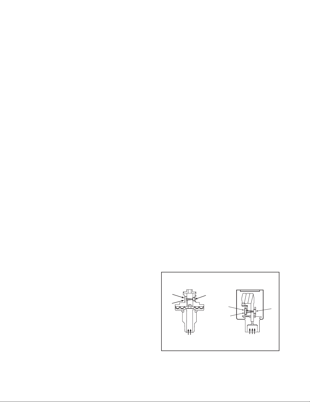
Theory of Operation
The PX624 pressure transducer uses an optical means
of detecting the effective pressure acting on an elastic
member (an Inconel diaphragm up to 250 psi and an
Inconel Bourdon tube above 250 psi), therefore, there is
no physical contact between the force summing element and the means by which the electrical output signal is produced. This unique sensor design results in
extraordinary repeatability and accuracy.
The basic operation of the sensor is simple. The
diaphragm or Bourdon tube element moves only 0.020
of an inch during a full span pressure excursion. This
small motion combined with the use of high strength
materials result in minimum stress levels, well below
metal yield points, to assure stability, repeatability, and
long sensor life. Attached to the diaphragm or Bourdon
tube is an opaque vane, the movement of which is
sensed by an optical system comprised of an LED light
source adjacent to a monolithic dual diode package.
See figure 1 below.
Figure 1. Sensor Cutaway
BOURDON TUBEDIAPHRAGM
Ref.
Diode
Meas.
Diode
Measured Pressure
LED
Ref.
Diode
Meas.
Diode
LED
Measured Pressure
Page 4

One diode serves as a reference output and the other as
a measuring output. The position of the vane (dependent upon the applied pressure) determines how much
of the measuring photodiode’s active surface is
exposed to the LED light source. The output of the reference diode is used to regulate power supplied to the
LED to insure consistent light levels. The measuring
diode’s output current is converted to voltage which is
further processed by the transducer’s analog conditioning circuitry to produce the desired voltage or current output.
IMPORTANT – SEALED HOUSING AND VENT
INFORMATION
Gauge, Vacuum and Compound Pressure Types
Changes in ambient temperature will affect the pressure of a fixed volume of gas on the order of approximately .03 psi per degree Fahrenheit. Since all units are
supplied with a NEMA 4X sealed housing, this may be
a significant effect when compared to the instrument’s
accuracy rating particularly on low pressure ranges.
The standard pigtail connector includes an integral
vent tube which prevents pressure changes within the
housing from affecting the output signal.
The optional Bendix PTO connector has no provision
for a vent tube. A sealed, # 2-56 screw located on the
bottom of the housing adjacent to the pressure inlet fitting (see page 10) can be removed to provide ventilation of the housing. Removal of this screw does,
however, invalidate the NEMA 4X rating. As an alternative the housing is also available with an optional
atmospheric reference port which can be connected to
a protected junction box or reference manifold.
Absolute Pressure Types
Absolute pressure instruments employ an evacuated
reference chamber integral to the sensor. This design is
immune from the effects of pressure changes within
the sealed housing and therefore requires no special
attention for either type of connector.
PRESSURE CONNECTION
Ranges up to and including 5000 psi are supplied with
a
1
⁄
4 NPT male pressure fitting. Ranges above 5000 psi
are supplied with a
9
⁄
16-18 UNF female port for
1
⁄
4 inch
O.D. high pressure tubing.
ELECTRICAL CONNECTION
The unit is provided with either a three foot pigtail
(standard) or a Bendix PTO2 (optional) connector as
specified at time of purchase. There are three basic signal output configurations also specified at time of purchase. They are non-isolated voltage, transformer
isolated voltage and current output.
Cable recommendations, Grounding
Shielded, number 26 AWG (minimum) cable is generally recommended as a starting point for all installa-
tions. Actual gage will depend on distance (I/R drop)
considerations. Shield drain wires should be terminated at one end only, usually at the data acquisition or
display device. Terminating the shield at both ends will
eliminate the effectiveness of the shield and may also
contribute to ground loop problems.
In each configuration the sensor body is electrically isolated from the power supply and output signal circuitry. Each output type includes either an orange wire
(pigtail) or connection at pin E (Ben-dix) which is tied
to the sensor body. This is provided to offer an earth
ground point if required by NEC or local electrical codes.
NOTE: It is not advisable to connect supply (–), signal
(–), or shield to this reference as it may contribute to
noise sensitivity or ground loop effects.
The connector assignments are per the following tables.
TABLE I: VOLTAGE OUTPUT – NON-ISOLATED
(3 Wire)
Although the non-isolated voltage output (0 to 5, 0 to
10, or -5 to +5 Vdc) offers four connections for power
supply and signal output it is actually a “three wire”
system in that the power supply (–) and signal (–) share
the same reference. A separate signal (–) is offered to
help reduce the effects of I/R drop in system installation wiring.
Pigtail Bendix Function
Red A 20-40 Vdc Supply (+)
Black B 20-40 Vdc Supply (– common)
C No Connect
White D Output Signal (+)
Orange E Sensor Body
Green F Output Signal (– common)
TABLE II: VOLTAGE OUTPUT – ISOLATED
(4 Wire)
The optional transformer isolated voltage output offers
superior immunity to EMI/RFI interference, ground
loop effects, and I/R drop. Shielded, twisted pair cable
is recommended for all installation wiring.
Pigtail Bendix Function
Red A 15-24 Vdc Supply (+)
Black B 15-24 Vdc Supply (–)
C No Connect
White D Output Signal (+)
Orange E Sensor Body
Green F Output Signal (–)
TABLE III: CURRENT OUTPUT – 4/20mA
Current loop signals offer naturally high noise immunity; however, shielded cable still may be desirable in
extremely noisy environments. Note that a minimum
of 12 Vdc must be present at the unit’s input terminals
and is dependent on the sampling resistance of the
acquisition or display device. This can easily be determined by the following formula:
Page 5

Supply min. (Vdc) = 12 Vdc + [.02 x (total loop
resistance)]
Pigtail Bendix Function
Red A 12-24 Vdc Supply (+)
Black B Common (–)
C No Connect
White D No Connect
Orange E Sensor Body
Green F No Connect
INSTALLATION ADJUSTMENTS AND FIELD
CALIBRATION
Zero should be adjusted as part of the initial installation procedure. Other field adjustments are limited to
setting span as compared to a suitable deadweight
tester. A primary standard with and accuracy of
±0.01% of reading is recommended. Note: Zero and
span adjustment of absolute pressure types require an
absolute pressure standard and a vacuum pump. Zero
and span adjustment of vacuum and compound pressure types will require a vacuum standard.
There are two adjustment potentiometers available to
the user. They are located on the top of the housing and
are accessed by removing the screws labeled “Z” (zero)
and “S” (span). These adjustments are referenced to the
full pressure span of the instrument and provide
approximately ±3% FS adjustment range.
Connect the transducer to a suitable pressure source
and display device. Apply power and allow at least 45
minutes for warm up before making any adjustments.
The adjustment procedure is dependent on the pressure type as described in the following sections.
GAUGE PRESSURE TYPE
ZERO
– Check the zero indication on the display
device with the pressure inlet open to atmospheric
pressure. If it does not indicate zero use a small screwdriver to turn the potentiometer labeled “Z” counterclockwise to reduce the reading or clockwise to
increase the reading until a display value corresponding to zero pressure is achieved.
SPAN – Apply full pressure and adjust the potentiometer labeled “S” as required. Release the pressure and
verify the zero adjustment. Repeat process if necessary
until the zero and full scale readings conform to the
pressure standard.
VACUUM PRESSURE TYPE
ZERO
– Check the zero indication on the display
device with the pressure inlet open to atmospheric
pressure. If it does not indicate zero use a small screwdriver to turn the potentiometer labeled “Z” counterclockwise to reduce the reading or clockwise to
increase the reading as required.
SPAN – Apply full scale vacuum and adjust the poten-
tiometer labeled “S” as required. Release the vacuum
and verify the zero adjustment. Repeat process if necessary until the zero and span readings conform to the
pressure standard.
NOTE – Units supplied with full vacuum ranges are
based on 0 to 14.7 psi vacuum or 0 to 30 in.Hg. As this
vacuum level is difficult to achieve, 14.5 psi vacuum or
29 in.Hg should be used as the span adjustment pressure (vacuum) value The span potentiometer should
then be adjusted to achieve 98.64% of the full span
voltage or current output at 14.5 psi vacuum or 96.66%
of the full span voltage or current output at 29 in.Hg
vacuum. For example:
A. 14.7 psi Vacuum Scale
The span adjustment should be made at 14.5 psiv with
a target output of 9.864 Vdc for a 0 to 10 Vdc output or
19.782 mA for a 4 to 20mAoutput.
B. 30 in.Hg Scale
The span adjustment should be made at 29 in.Hg with
a target output of 9.667 Vdc for a 0 to 10 Vdc output or
19.467 mA for a 4 to 20mAoutput.
COMPOUND PRESSURE TYPE
TYPES OF SIGNAL OUTPUT
A compound range PX624 is available with one of two
output configurations depending on the original
purchase specification. Symetrical pressure ranges
such as –3 to 3 psi, –14.7 to 14.7 psi, etc. are available
with a uni-polar (0 to 5 or 10 Vdc or 4-20mA) output or
an optional hi-polar voltage (–5 to +5 Vdc) output.
Non-symetrical pressure ranges such as –14.7 to 30 psi
are only available with uni-polar (0 to 5 or 10VDC or
4-20mA) outputs.
ZERO – A vacuum standard is required for adjusting
zero on a compound range unit. The zero potentiometer affects the full vacuum point of the pressure rating
(not the gauge pressure zero). For example, the zero
adjustment on a transducer with a pressure range of
14.7 to 15 psi is made at –14.5 psiv or for –28 to 30
in.Hg the zero adjustment is made at 29 in.Hg (see
instructions for vacuum pressure type in the preceeding section).
SPAN – Apply full scale pressure and adjust the span
potentiometer as required. Release pressure and verify
“zero” adjustment. Repeat if required. With zero and
span properly adjusted the unit should read zero ±
0.05% of its full span rating.
ABSOLUTE PRESSURE TYPE
ZERO
– An absolute pressure standard with a vacuum
pump capable of achieving a vacuum level of at least
one half the value of the least significant digit of its
pressure range resolution will be required (a vacuum
level of 50 microns absolute is used at the factory).
Page 6

Connect the unit to the pressure standard and evacuate.
If the signal output varies from an indication of zero
adjust the zero potentiometer labeled (Z) as required.
SPAN – Apply full scale absolute pressure and adjust
the span potentiometer labeled “S” as required. Verify
the zero and repeat if required.
GENERAL SPECIFICATIONS
PERFORMANCE
Accuracy:
±0.05% of span (including non-linearity,
hysteresis and nonrepeatability) at reference conditions
(72°F)
Repeatability: ±0.005% of span
Resolution: ±0.01% FS
Temperature Compensated Range: 20 to 120°F
(–7 to + 49°C)
Operating Temperature Range: 0 to 180°F (–18 to 83°C)
Temperature Effects Over Compensated Range:
±0.004% per °F. (.002% per °C) for both zero and span
Warm Up: 5 minutes to rated accuracy 45 minutes for
complete stability
FUNCTIONAL CHARACTERISTICS
Ranges:
0-5 psi to 0-1 0,000 psi
Pressure Types: Gauge, Absolute, Compound and
Vacuum
Output Signal: 0/5 or 0/10 Vdc into a load of 5k ohms
or greater, 3 wire non-isolated or 4 wire isolated, and 420mA
Power Requirements: 20-40 Vdc (non-isolated 3 wire
voltage output), 15-24 Vdc (isolated 4 wire output), 1224 Vdc (current output)
Power Supply Effect: Less than ±0.002% of span per 1
volt change
Overpressure Limits:
400% of span 0/5 to 0/250 psi
30% of span 0/300 to 10,000 psi
Sensor Volume: Approximately 4 cc 0/5 to 0/250 psi
and 0.38 cc from 0/300 to 0/10,000 psi
Volume Displacement: Approximately 0.5 cc to 250
psi. Negligible for ranges above 250 psi
Response Time: 3 mS
Frequency Response: Approximately 300 Hz
Wetted Materials: Inconel and 300 Series Stainless Steel
(all welded construction)
Media Compatibility: Gas, vapor or liquid non corro-
sive to Inconel or 300 Series Stainless Steel
Mounting Position Effects: Less than the following
values per 30 degree inclination in any plane for
zero
only – no span effect:
±0.05% of span up to 250 psi,
±0.3% of span ranges above 250 psi.
Correctable by zero adjustment after final installation orientation.
PHYSICAL CHARACTERISTICS
Process Connection: 1⁄
4 male NPT for 5 psi through
5000 psi –
9
⁄
16-18 female port for
1
⁄
4 inch O.D. high pres-
sure tubing for ranges over 5000 psi.
Electrical Connector: 1 Meter vented pigtail (stan-
dard), Bendix PTO2, 6 Pin (optional)
Housing: Sealed NEMA 4X, 300 Series Stainless Steel
Mounting: Stem Mount (standard) – Wall/Pipe
Bracket (optional)
Dimensions: Diameter: 2.0 inches, Height: See table
below
Weight: 16 oz.
Table 1: Overall Height Dimensions
Pigtail Bendix
Connector Connector
1
⁄
4 NPT 4.904 4.977
9
⁄
16-l8 4.571 4.644
Page 7

WARRANTY/DISCLAIMER
OMEGA ENGINEERING, INC. warrants this unit to be free of defects in materials and workmanship for a
period of
13 months from date of purchase. OMEGA’s Warranty adds an additional one (1) month grace
period to the normal
one (1) year product warranty to cover handling and shipping time. This
ensures that OMEGA’s customers receive maximum coverage on each product.
If the unit malfunctions, it must be returned to the factory for evaluation. OMEGA’s Customer Service
Department will issue an Authorized Return (AR) number immediately upon phone or written request.
Upon examination by OMEGA, if the unit is found to be defective, it will be repaired or replaced at no
charge. OMEGA’s WARRANTY does not apply to defects resulting from any action of the purchaser,
including but not limited to mishandling, improper interfacing, operation outside of design limits,
improper repair, or unauthorized modification. This WARRANTY is VOID if the unit shows evidence of
having been tampered with or shows evidence of having been damaged as a result of excessive corrosion;
or current, heat, moisture or vibration; improper specification; misapplication; misuse or other operating
conditions outside of OMEGA’s control. Components which wear are not warranted, including but not
limited to contact points, fuses, and triacs.
OMEGA is pleased to offer suggestions on the use of its various products. However, OMEGA
neither assumes responsibility for any omissions or errors nor assumes liability for any damages
that result from the use of its products in accordance with information provided by OMEGA, either
verbal or written. OMEGA warrants only that the parts manufactured by it will be as specified and
free of defects. OMEGA MAKES NO OTHER WARRANTIES OR REPRESENTATIONS OF ANY KIND
WHATSOEVER, EXPRESS OR IMPLIED, EXCEPT THAT OF TITLE, AND ALL IMPLIED WARRANTIES
INCLUDING ANY WARRANTY OF MERCHANTABILITY AND FITNESS FOR A PARTICULAR PURPOSE ARE HEREBY DISCLAIMED. LIMITATION OF LIABILITY: The remedies of purchaser set forth
herein are exclusive, and the total liability of OMEGA with respect to this order, whether based on
contract, warranty, negligence, indemnification, strict liability or otherwise, shall not exceed the
purchase price of the component upon which liability is based. In no event shall OMEGA be liable
for consequential, incidental or special damages.
CONDITIONS: Equipment sold by OMEGA is not intended to be used, nor shall it be used: (1) as a “Basic
Component” under 10 CFR 21 (NRC), used in or with any nuclear installation or activity; or (2) in medical
applications or used on humans. Should any Product(s) be used in or with any nuclear installation or
activity, medical application, used on humans, or misused in any way, OMEGA assumes no responsibility
as set forth in our basic WARRANTY/ DISCLAIMER language, and, additionally, purchaser will indemnify
OMEGA and hold OMEGA harmless from any liability or damage whatsoever arising out of the use of the
Product(s) in such a manner.
RETURN REQUESTS / INQUIRIES
Direct all warranty and repair requests/inquiries to the OMEGA Customer Service Department. BEFORE
RETURNING ANY PRODUCT(S) TO OMEGA, PURCHASER MUST OBTAIN AN AUTHORIZED RETURN (AR)
NUMBER FROM OMEGA’S CUSTOMER SERVICE DEPARTMENT (IN ORDER TO AVOID PROCESSING
DELAYS). The assigned AR number should then be marked on the outside of the return package and on
any correspondence.
The purchaser is responsible for shipping charges, freight, insurance and proper packaging to prevent
breakage in transit.
FOR
W
ARRANTY
RETURNS, please have the
following information available BEFORE
contacting OMEGA:
1. Purchase Order number under which the product
was PURCHASED,
2. Model and serial number of the product under
warranty, and
3. Repair instructions and/or specific problems
relative to the product.
FOR NON-WARRANTY REPAIRS,
consult OMEGA
for current repair charges. Have the following
information available BEFORE contacting OMEGA:
1. Purchase Order number to cover the COST
of the repair,
2. Model and serial number of the product, and
3. Repair instructions and/or specific problems
relative to the product.
OMEGA’s policy is to make running changes, not model changes, whenever an improvement is possible. This affords
our customers the latest in technology and engineering.
OMEGA is a registered trademark of OMEGA ENGINEERING, INC.
© Copyright 1999 OMEGA ENGINEERING, INC. All rights reserved. This document may not be copied, photocopied,
reproduced, translated, or reduced to any electronic medium or machine-readable form, in whole or in part, without the
prior written consent of OMEGA ENGINEERING, INC.
MADE IN
Page 8

DPS-5C-1P-10/99 M3332/0499
Where Do I Find Everything I Need for
Process Measurement and Control?
OMEGA…Of Course!
TEMPERATURE
Thermocouple, RTD & Thermistor Probes, Connectors, Panels & Assemblies
Wire: Thermocouple, RTD & Thermistor
Calibrators & Ice Point References
Recorders, Controllers & Process Monitors
Infrared Pyrometers
PRESSURE, STRAIN AND FORCE
Transducers & Strain Gages
Load Cells & Pressure Gages
Displacement Transducers
Instrumentation & Accessories
FLOW/LEVEL
Rotameters, Gas Mass Flowmeters & Flow Computers
Air Velocity Indicators
Turbine/Paddlewheel Systems
Totalizers & Batch Controllers
pH/CONDUCTIVITY
pH Electrodes, Testers & Accessories
Benchtop/Laboratory Meters
Controllers, Calibrators, Simulators & Pumps
Industrial pH & Conductivity Equipment
DATA ACQUISITION
Data Acquisition & Engineering Software
Communications-Based Acquisition Systems
Plug-in Cards for Apple, IBM & Compatibles
Datalogging Systems
Recorders, Printers & Plotters
HEATERS
Heating Cable
Cartridge & Strip Heaters
Immersion & Band Heaters
Flexible Heaters
Laboratory Heaters
ENVIRONMENTAL
MONITORING AND CONTROL
Metering & Control Instrumentation
Refractometers
Pumps & Tubing
Air, Soil & Water Monitors
Industrial Water & Wastewater Treatment
pH, Conductivity & Dissolved Oxygen Instruments
 Loading...