

Page 1
®
PX540 Series
Pressure Transducers
Operator’s Manual: M1137/0698
General Description
The OMEGA
®
PX540 Pressure Transducer consists of a pressure connection section with welded stainless steel
diaphragm and a case for housing the electronic equipment and the electrical connection. The piezoresistive pressure sensor is installed behind the diaphragm, with the intervening space filled with silicone oil as pressure transmission liquid.
The pressure sensor’s signal is converted by an amplifier to a signal of 4 to 20 mA. The pressure connection DIN
3852 is used as a seal behind threads by means of the added NBR O-ring. (No flush-mounted seal).
Characteristics of this transducer include:
• 4 to 20 mA current output which is ideal for long distance signal transmitting and industrial environments.
• High accuracy and repeatability.
• Corrosion resistant, and
• Rugged NEMA=12 dust-tight/drip-tight enclosure.
How To Adjust Zero and Span
NOTE:
Unit has been factory calibrated. No adjustment is
required upon delivery from OMEGA Engineering.
Zero adjustment must be performed at no pressure
and the output reading must be 4 mA.
Span adjustment must be performed at full scale pressure and the output reading must be 20 mA.
If you do not get either of these readings at the
required no pressure or full scale pressure, go through
the following procedure to get to the screws.
Remove the connector from the body of the transmitter as described in steps 1 and 2 in the Wiring Section.
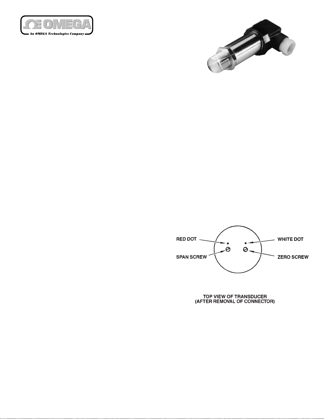
Adjust the zero screw so the output reading is 4 mA at
no pressure. At full scale pressure, the output must be
20 mA; if it is not, adjust the span screw.
The Zero screw is marked with a white dot. The span
screw is marked with a red dot. Refer to Figure 1.
Figure 1.
Location of Adjustment
Screws
Page 2
Wiring
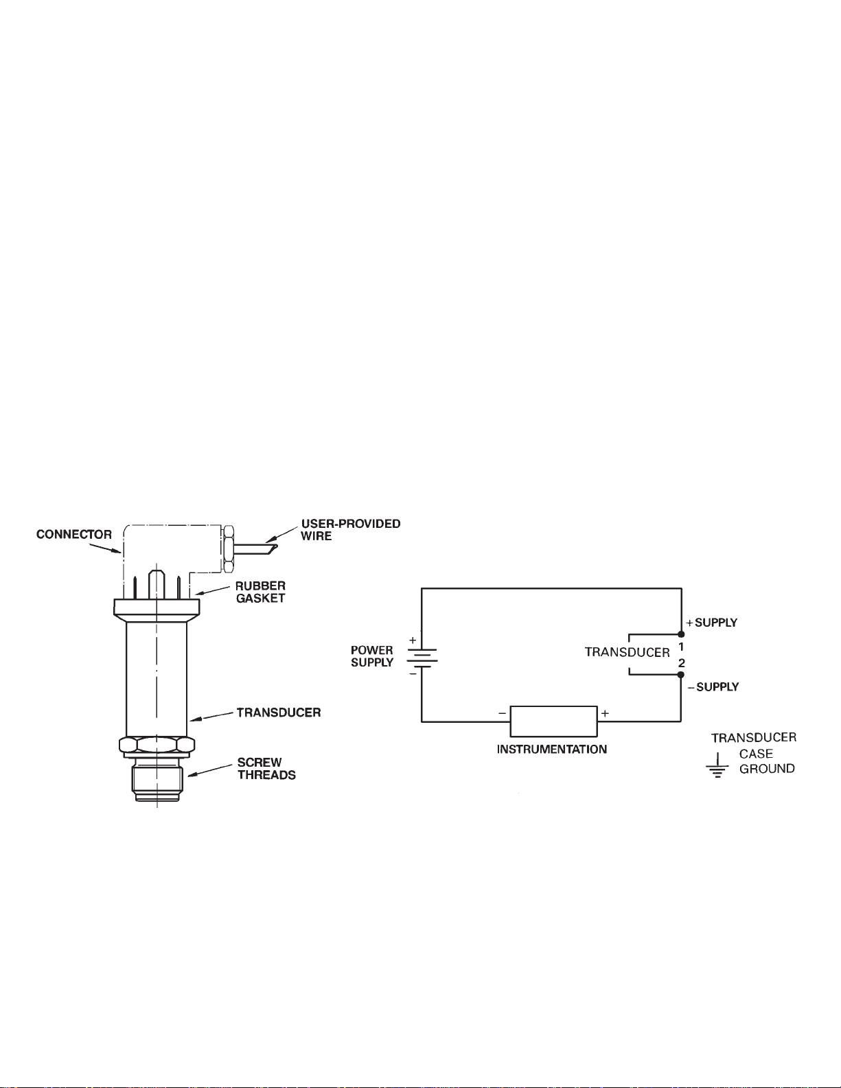
To access the screw terminals and wire the transducer, refer to Figure 2, and the following procedure.
1. Locate the screw at the top of the transducer and unscrew.
2. Separate connector from the rest of the transducer body. Remove the screw and rubber gasket from the connector and set aside.
3. Using a small blade screwdriver, insert it in the corner slot and pry off square cover (and terminals).
4. Insert cable into hole (not screw hole) and feed through into square part of assembly. Wire terminals in terminal
block using wiring diagram (refer to Figure 3).
5. Replace terminal block and snap in place.
6. Put rubber gasket on unit.
7. Connect larger part of transducer to wired unit observing positions of blades.
8. Insert screw in screw hole and tighten two parts to each other.
Figure 2.
Pressure Transducer
Figure 3.
Wiring Diagram
Page 3

Specifications
Excitation: 10 to 30 VDC
Output: 4 to 20 mA two wire
Insulation Resistance: 500 VAC
Maximum Loop Impedance: (Supply Voltage -10) x 50 (refer to Figure 4)
Performance
Accuracy: 0.3% F.S. Typ (0.5% max)
Hysteresis and Repeatability: 0.1% F.S.
Compensated Temperature Range: 32˚ to 122˚ F (0˚ to 50˚ C)
Operating Temperature Range: -4˚ to 175˚ F (-20˚ to 80˚ C)
Thermal Zero Effect: 0.03% F.S./˚ C
Thermal Sensitivity Effect: 0.03% F.S>/˚ C
Maximum Pressure: 150% Full Scale
Construction
Body Material: Stainless steel
Wetted Parts: ANSI 316L Stainless steel
Fill Fluid: Silicone oil
Process Connection: 1/2 NPT male
Electrical Connection: DIN connector with screw terminals
Response Time: 2 ms
Weight: 0.35 lb.
Dimensions: Refer to Figure 5.
WARNING!
Read Before Installation
Fluid hammer and surges can destroy any pressure transducer and must always be avoided. A pressure snubber should be installed to eliminate the damaging hammer effects.
Fluid hammer occurs when a liquid flow is suddenly stopped, as with quick closing solenoid valves. Surges
occur when flow is suddenly begun, as when a pump is turned on at full power or a valve is quickly opened.
Liquid surges are particularly damaging to pressure transducers if the pipe is originally empty. To avoid damaging surges, fluid lines should remain full (if possible), pumps should be brought up to power slowly, and
valves opened slowly. To avoid damage from both fluid hammer and surges, a surge chamber should be
installed, and a pressure snubber should be installed on every transducer.
Symptoms of fluid hammer and surge’s damaging effects:
a) Pressure transducer exhibits an output at zero pressure (large zero offset). If zero offset is less than 10% F.S.,
user can usually re-zero meter, install proper snubber and continue monitoring pressures.
b) Pressure transducer output remains constant regardless of pressure.
c) In severe cases, there will be no output.
Page 4

Benelux:
Postbus 8034, 1180 LA Amstelveen,
The Netherlands
Tel: (31) 20 6418405 FAX: (31) 20 6434643
Toll Free in Benelux: 06 0993344
e-mail: nl@omega.com
Czech Republic:
ul. Rude armady 1868, 733 01 Karvina-Hranice,
Czech Republic
Tel: 420 (69) 6311899 FAX: 420 (69) 6311114
e-mail: czech@omega.com
France:
9, rue Denis Papin, 78190 Trappes
Tel: (33) 130-621-400 FAX: (33) 130-699-120
Toll Free in France: 0800-4-06342
e-mail: france@omega.com
Servicing Europe:
USA and Canada:
Sales Service: 1-800-826-6342 / 1-800-TC-OMEGA
SM
Customer Service: 1-800-622-2378 / 1-800-622-BEST
SM
Engineering Service: 1-800-872-9436 /
1-800-USA-WHEN
SM
TELEX: 996404
EASYLINK: 62968934 CABLE: OMEGA
USA: ISO 9001 Cer
tified
One Omega Drive, Box 4047
Stamford, CT 06907-0047
Tel: (203) 359-1660
FAX: (203) 359-7700
e-mail: info@omega.com
Servicing North America:
For immediate technical or application assistance:
Mexico and Latin America:
Tel: (95) 800-TC-OMEGA
SM
FAX: (95) 203-359-7807
En Espan~ol: (203) 359-7803
e-mail: espanol@omega.com
Germany/Austria:
Daimlerstrasse 26, D-75392
Deckenpfronn, Germany
Tel: 49 (07056) 3017 FAX: 49 (07056) 8540
Toll Free in Germany: 0130 11 21 66
e-mail: germany@omega.com
United Kingdom: ISO 9002 Cer
tified
•One Omega Drive, Riverbend Tech Centre,
Northbank, Irlam,
Manchester, M44 5BD, England
Tel: 44 (161) 777-6611 FAX: 44 (161) 777-6622
Toll Free in England: 0800-488-488
e-mail: uk@omega.com
Canada:
976 Bergar
Laval (Quebec) H7L 5A1
Tel: (514) 856-6928
FAX: (514) 856-6886
e-mail: canada@omega.com
®
OMEGAnetSMOn-Line Service Internet e-mail
http://www.omega.com info@omega.com
RETURN REQUESTS / INQUIRIES
Direct all warranty and repair requests/inquiries to the OMEGA ENGINEERING Customer Service
Department. BEFORE RETURNING ANY PRODUCT(S) TO OMEGA, PURCHASER MUST OBTAIN AN
AUTHORIZED RETURN (AR) NUMBER FROM OMEGA’S CUSTOMER SERVICE DEPARTMENT (IN
ORDER TO AVOID PROCESSING DELAYS). The assigned AR number should then be marked on the
outside of the return package and on any correspondence.
FOR W
ARRANTY RETURNS, please have the
following information available BEFORE contacting OMEGA:
1. P.O. number under which the product was
PURCHASED,
2. Model and serial number of the product
under warranty, and
3. Repair instructions and/or specific problems
relative to the product.
FOR NON-WARRANTY REPAIRS OR CALIBRA-
TION,
consult OMEGA for current repair/calibration charges. Have the following information available BEFORE contacting OMEGA:
1. P.O. number to cover the COST of the
repair/calibration,
2. Model and serial number of product, and
3. Repair instructions and/or specific
problems relative to the product.
OMEGA’s policy is to make running changes, not model changes, whenever an improvement is possible. This
affords our customers the latest in technology and engineering.
OMEGA is a registered trademark of OMEGA ENGINEERING, INC.
© Copyright 1995 OMEGA ENGINEERING, INC. All rights reserved. This documentation may not be copied, pho-
tocopied, reproduced, translated, or reduced to any electronic medium or machine-readable form, in whole or
in part, without prior written consent of OMEGA ENGINEERING, INC.
WARRANTY
OMEGA warrants this unit to be free of defects in materials and workmanship and to give satisfactory service for a period of 13 months from date of purchase. OMEGA Warranty adds an additional one
(1) month grace period to the normal one (1) year product warranty to cover handling and shipping time. This ensures that OMEGA’s customers receive maximum coverage on each product. If the
unit should malfunction, it must be returned to the factory for evaluation. OMEGA’s Customer Service
Department will issue an Authorized Return (AR) number immediately upon phone or written request.
Upon examination by OMEGA, if the unit is found to be defective it will be repaired or replaced at no
charge. However, this WARRANTY is VOID if the unit shows evidence of having been tampered with
or shows evidence of being damaged as a result of excessive corrosion; or current, heat, moisture or
vibration; improper specification; misapplication; misuse or other operating conditions outside of
OMEGA’s control. Components which wear or which are damaged by misuse are not warranted. These
include contact points, fuses, and triacs.
OMEGA is glad to offer suggestions on the use of its various products. Nevertheless,
OMEGA only warrants that the parts manufactured by it will be as specified and free of
defects.
OMEGA MAKES NO OTHER WARRANTIES OR REPRESENTATIONS OF ANY KIND WHATSOEVER, EXPRESSED OR IMPLIED, EXCEPT THAT OF TITLE AND ALL IMPLIED WARRANTIES
INCLUDING ANY WARRANTY OF MERCHANTABILITY AND FITNESS FOR A PARTICULAR
PURPOSE ARE HEREBY DISCLAIMED.
LIMITATION OF LIABILITY: The remedies of purchaser set forth herein are exclusive and the
total liability of OMEGA with respect to this order, whether based on contract, warranty,
negligence, indemnification, strict liability or otherwise, shall not exceed the purchase
price of the component upon which liability is based. In no event shall OMEGA be liable
for consequential, incidental or special damages.
Every precaution for accuracy has been taken in the preparation of this manual; however, OMEGA
ENGINEERING, INC. neither assumes responsibility for any omissions or errors that may appear nor
assumes liability for any damages that result from the use of the products in accordance with the information contained in the manual.
SPECIAL CONDITION: Should this equipment be used in or with any nuclear installation or activity,
purchaser will indemnify OMEGA and hold OMEGA harmless from any liability or damage whatsoever arising out of the use of the equipment in such a manner.
Figure 5. Dimensional Diagram
MADE
ININ
UUSASA
Page 5

Over 100,000 Products Available
Online at omega.com
TEMPERATURE
MU
Thermocouple, RTD & Thermistor Probes, Connectors, Panels & Assemblies
MU
Calibrators & Ice Point References
MU
Recorders, Controllers & Process Monitors
MU
Infrared Pyrometers
PRESSURE, STRAIN AND FORCE
MU
Transducers & Strain Gages
MU
Displacement Transducers
MU
Instrumentation & Accessories
FLOW/LEVEL
MU
Rotameters, Gas Mass Flowmeters & Flow Computers
MU
Air Velocity Indicators
MU
Turbine/Paddlewheel Systems
pH/CONDUCTIVITY
MU
pH Electrodes, Testers & Accessories
MU
Benchtop/Laboratory Meters
MU
Controllers, Calibrators, Simulators & Pumps
MU
Industrial pH & Conductivity Equipment
DATA ACQUISITION
MU
Data Acquisition & Engineering Software
MU
Communications-Based Acquisition Systems
MU
Plug-in Cards for Apple, IBM & Compatibles
MU
Recorders, Printers & Plotters
HEATERS
MU
Heating Cable, Cartridge & Strip Heaters
MU
Immersion & Band Heaters
MU
Flexible Heaters
ENVIRONMENTAL
MONITORING AND CONTROL
MU
Metering & Control Instrumentation
MU
Pumps & Tubing
MU
Air, Soil & Water Monitors
MU
Industrial Water & Wastewater Treatment
www.omega.com
ONE OMEGA DRIVE, STAMFORD, CT 06907 USA
TEL: 1-888-TC-OMEGA
(1-888-826-6342)
 Loading...