

Page 1
Installation and Maintenance
omega.comomega.com
TM
®
Instructions for OMEGA
®
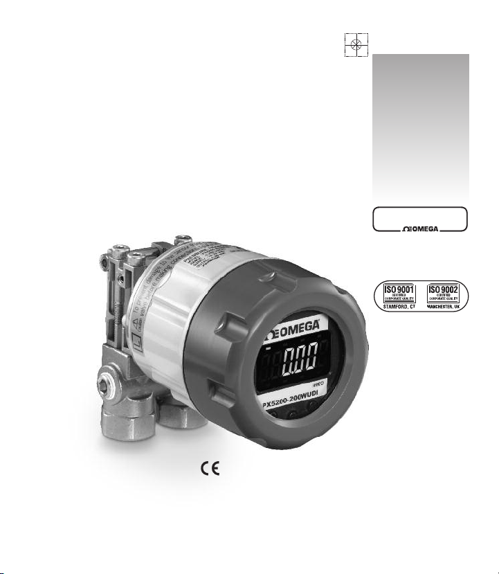
PX5200 Differrential Pressure
Transmitter M-5109/0112
User’s Guide
Shop online at
omega.com
omegamanual.info
LOOK FOR THIS
AGENCY MARK ON
OUR PRODUCTS
e-mail: info@omega.com
For latest product manuals:
Version 6.03 5/11
PX5200
M5109/0212
Page 2
OMEGAnet®Online Service Internet e-mail
omega.comomega.com
T
M
®
omega.com info@omega.com
Servicing North America:
U.S.A.: Omega Engineering, Inc., One Omega Drive, P.O. Box 4047
ISO 9001 Certified
Canada: 976 Bergar
Stamford, CT 06907-0047
Toll-Free: 1-800-826-6342 Tel: (203) 359-1660
FAX: (203) 359-7700 e-mail: info@omega.com
Laval (Quebec), Canada H7L 5A1
Toll-Free: 1-800-826-6342 TEL: (514) 856-6928
FAX: (514) 856-6886 e-mail: info@omega.ca
For immediate technical or application assistance:
U.S.A. and Canada: Sales Service: 1-800-826-6342/1-800-TC-OMEGA
Mexico: En Español: 001 (203) 359-7803 FAX: (001) 203-359-7807
Customer Service: 1-800-622-2378/1-800-622-BEST
Engineering Service: 1-800-872-9436/1-800-USA-WHEN
info@omega.com.mx e-mail: espanol@omega.com
®
®
®
Servicing Europe:
Benelux: Managed by the United Kingdom Office
Czech Republic: Frystatska 184
France: Managed by the United Kingdom Office
Germany/Austria: Daimlerstrasse 26
United Kingdom: OMEGA Engineering Ltd.
ISO 9001 Certified
Toll-Free: 0800 099 3344 TEL: +31 20 347 21 21
FAX: +31 20 643 46 43 e-mail: sales@omega.nl
733 01 Karviná, Czech Republic
Toll-Free: 0800-1-66342 TEL: +420-59-6311899
FAX: +420-59-6311114 e-mail: info@omegashop.cz
Toll-Free: 0800 466 342 TEL: +33 (0) 161 37 29 00
FAX: +33 (0) 130 57 54 27 e-mail: sales@omega.fr
D-75392 Deckenpfronn, Germany
Toll-Free: 0 800 6397678 TEL: +49 (0) 7059 9398-0
FAX: +49 (0) 7056 9398-29 e-mail: info@omega.de
One Omega Drive, River Bend Technology Centre, Northbank
Irlam, Manchester M44 5BD England
Toll-Free: 0800-488-488 TEL: +44 (0)161 777-6611
FAX: +44 (0)161 777-6622 e-mail: sales@omega.co.uk
It is the policy of OMEGA Engineering, Inc. to comply with all worldwide safety and EMC/EMI
regulations that apply. OMEGA is constantly pursuing certification of its products to the European
New Approach Directives. OMEGA will add the CE mark to every appropriate device upon
certification.
The information contained in this document is believed to be correct, but OMEGA accepts no liability for any
errors it contains, and reserves the right to alter specifications without notice.
WARNING: These products are not designed for use in, and should not be used for, human applications.
2
Page 3

CONTENTS
CAUTION................................................................................................ 4-5
1. PREFACE.............................................................................................. 5
2. OVERVIEW .......................................................................................... 5
3. FEATURES............................................................................................ 5
4. SPECIFICATIONS .................................................................................. 6
5. MOUNTING .......................................................................................... 8
5.1 Mounting Location........................................................................ 8
5.2 Mounting Options ........................................................................ 8
5.3 Pressure Connection.................................................................... 8
6. PIPING ................................................................................................ 9
7. WIRING................................................................................................ 10
7.1 Cable / Wiring Specifications........................................................ 10
7.2 Wiring Instructions........................................................................ 10
8. DISPLAY FUNCTIONS ............................................................................ 13
9. MODE CHANGES .................................................................................. 14
10. POWER-ON MESSAGE .......................................................................... 14
11. MEASUREMENT MODE .......................................................................... 15
11.1 Filter (Damping) .......................................................................... 15
11.2 Pressure Display Mode (Re-scaling in “inH
O” units).................. 15
2
11.3 Linear Display Mode
(Re-scaling in arbitrary user defined units) .................................. 16
11.4 Flow Measurement/Square Root Extraction Mode...................... 19
11.5 Min/Max Display .......................................................................... 26
12. ZERO ADJUSTMENT MODE .................................................................... 27
13. KEY LOCK ............................................................................................ 28
14. SETTING MODE .................................................................................... 20
14.1 Setting Items for Pressure Display Mode
(Re-scaling in “inH
O” units) ........................................................ 28
2
14.2 Setting Items for Linear Display Mode
(Re-scaling in arbitrary user defined units) .................................. 29
14.3 Setting Items for Square Root Extraction (Flow Measurement) .. 31
14.4 Setting Procedure ........................................................................ 32
14.5 Loop Check .................................................................................. 34
15. DIMENSIONAL DRAWINGS .................................................................... 35
16. MAINTENANCE...................................................................................... 36
3
Page 4

WARNING! READ BEFORE INSTALLATION
GENERAL:
A failure resulting in injury or damage may be caused by excessive
overpressure, excessive vibration or pressure pulsation, excessive instrument temperature, corrosion of the pressure containing parts, or
other misuse.
OVERPRESSURE:
Pressure spikes in excess of the rated overpressure capability of the transmitter may cause irreversible electrical and/or mechanical damage to the
pressure measuring and containing elements.
Fluid hammer and surges can destroy any pressure transmitter and must always be avoided. A pressure snubber should be installed to eliminate the
damaging hammer effects. Fluid hammer occurs when a liquid flow is suddenly stopped, as with quick closing solenoid valves. Surges occur when flow
is suddenly begun, as when a pump is turned on at full power or a valve is
quickly opened.
Liquid surges are particularly damaging to pressure transmitters if the pipe is
originally empty. To avoid damaging surges, fluid lines should remain full (if
possible), pumps should be brought up to power slowly, and valves opened
slowly. To avoid damage from both fluid hammer and surges, a surge chamber
should be installed.
Symptoms of fluid hammer and surge’s damaging effects:
• Pressure transmitter exhibits an output at zero pressure (large zero offset).
• Pressure transmitter output remains constant regardless of pressure
• In severe cases, there will be no output.
FREEZING:
Prohibit freezing of media in pressure port. Unit should be drained to prevent
possible overpressure damage from frozen media.
STATIC ELECTRICAL CHARGES:
Any electrical device may be susceptible to damage when exposed to static
electrical charges. To avoid damage to the transmitter observe the following:
• Ground the body of the transmitter BEFORE making any electrical
connections.
• When disconnecting, remove the ground LAST!
4
Page 5

Note: The shield and drain wire in the cable (if supplied) is not connected to the
transmitter body, and is not a suitable ground.
1. PREFACE
Thank you for purchasing the PX5200 Rangeable Differential Pressure
Transmitter. Refer to the Omega PX5200 Data Sheet for product specifications and applicable operating conditions.
2. OVERVIEW
The PX5200 is a 4-20mA loop powered (two-wire) differential pressure
transmitter with integral display incorporating Ashcroft’s proven SiGlas silicon
based variable capacitance sensor with stainless steel media isolation diaphragms and silicone pressure transmission fluid. The device was designed
to offer the user small size and user adjustable ranging for applications such
as tank level measurements and gas / liquid flow measurements.
3. FEATURES
(1) Media Compatibility: Wetted materials consist of 316 stainless steel,
alumina ceramic and viton to handle a wide range of media with the
ability to offer ranges as low as 4˝ W.C. F.S. (URL).
(2) Linear Scaling Function:The linear (scaling) function allows the user
to adjust zero and span values providing a corresponding
4-20mA output signal.
(3) Flow Measurement/Square Root Extraction Function: Momentary
flow rate and integrated volume can be displayed and analog signal
can be output.
(4) Digital Filter Function: User adjustable damping of the output signal
by means of internally calculated moving average to provide a stable
output signal in applications where the user wants to reduce the pulsating of the display and / or output signal.
(5) LED Back Light: To supplement the LCD display when conditions re-
quire (dark area, night etc.).
(
6) Loop Check Function: Allows the user to output an analog signal cor-
responding to differential pressure without applying pressure, simplifying system maintenance and troubleshooting.
5
Page 6
(7) Zero and Span Adjustment: The adjustment of the Zero (4mA) and
Span (20mA) reading via internal push buttons.
(8) Key Lock Function: Prevents inadvertent overwriting of setting values.
Can not be reset by restoring power when activated.
(9) IP65 / NEMA 4X Environmental Rating: Enclosure environmental rat-
ing suitable for indoor and outdoor installation, depending upon operating temperature range.*
(10) CE Compliance: EN613261 1997, A1/1998, A2/2001 (Heavy Industrial).
*Display not to be mounted in direct sunlight.
4. SPECIFICATIONS
ITEM DESCRIPTION
1. Media/Wetted Parts
Gas or liquid compatible with 316SS, viton and alumina
ceramic (isolation fluid is silicone oil). Media temperature range: –10 to +70°C
2. Overpressure
(Proof)
Static (Line) Pressure: 300psi all ranges
Singe Side (Differential) Limits:
• Pressure Ranges <8˝W.C., ±4˝W.C.; 30psid
• Pressure Ranges >20˝W.C., ±8˝W.C.; 100psid
3. Supply Voltage
4. Output
12-32Vdc
4-20mAdc (two wires, Output range: 3.2 to 20.8mAdc)
Response Time: 100ms (with “0” filter setting)
Resolution: 0.1%F.S.,
Load resistance: 500Ω max.
5. Accuracy
±0.5% F.S. (URL) at 73°F (23°C); includes the effects of
non-linearity, hysteresis and non-repeatability)
6. Display Accuracy
±0.50% F.S. (URL) + 1 digit at 23°C
6
Page 7

7. Rangeability /
Adjustment
8. Display
9. Units
10. Setting Adjustments
11. Enclosure
12. Pressure Connection
13. Electrical
Termination
14. Memory Protection
15. EMC Directive
16. Operating
Temperature
17. Storage
Temperature
18. Vibration
19. Shock
20. Insulation
Resistance
21. Weight
Zero: –10 to +110% FS
Span: –10 to + 110% FS
Character height: 10mm, with LCD display with LED
backlight
Pressure / linear display: (4) LCD digits max.
Display update: 500 ms
Pressure Units: inH2O (2), (1) arbitrary
Internal key switches (Mode, T, S)
Scaling function: Linear output, linear and momentary
flow rate display/output.
Filter function: User adjustable output damping select
from 0, 2, 4, 8 and 16 (None, 2, 4, 8, and 16 (s)).
Loop check function: User adjustable output for loop/
system check and troubleshooting, 4-20mA.
Material: Aluminum die cast
Environmental Rating: IP65 / NEMA 4X
1
⁄4 NPT female pressure ports w/equalizing valve
Cable Gland (Optional): Cable diameter 0.35 to 0.47˝
(9-12mm)
1
⁄2 NPT Female Conduit Adapter (Optional)
Terminal Block: 14-22 AWG (stranded or solid wire)
Permanently stored by EEPROM (nonvolatile memory)
CE Compliance: EN61326/1997, A1/1998, A2/2001
–10 to 60°C (14 to 140°F)
–20 to 70°C (–4 to 158°F)
5g’s, 150Hz
10g’s, 16ms
50Vdc, 100MΩ or more
Approx. 670g (1.5lbs)
7
Page 8

5. MOUNTING
5.1 General
The GC52 was designed to be mounted using the bracket supplied.
Pressure connections via the (2)
1
⁄4 NPT female pressure ports. Al-
though the display can be rotated in 90 degree increments by removing the display cover it is preferable to orientate the electrical
termination downward, particularly in applications where protection
from the environment is required.
5.2 Mounting Orientation
It is preferable to orientate the unit with the pressure ports either
downward or upward. If mounting with pressure ports to the side an
“orientation effect” will be seen at zero pressure as the pressure generated by the silicone oil fill will appear as a zero offset. If mounting in
this manner this effect may be taken out by re-setting zero in final
mounting orientation.
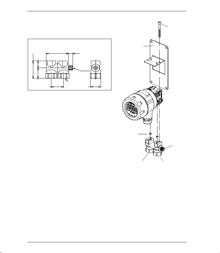
5.3 Installing Pressure Port Manifold
(1) Mounting 25.4mm Manifold (
1
⁄4˝ NPT female ports)
Manifold is secured using the (4) socket head bolts (M4x40) and
appropriate allen wrench which is supplied. Check for dust and
dirt on the O-ring and seal area, clean if necessary, before installing to ensure proper connection. The direction of the manifold
is not important, determine best position by ability to operate the
equalizing valve.The equalizing valve is used to open both ports
to the line pressure at time of installation. Once installed and the
system has been pressurized the valve needs to be closed to isolate the low and high pressure sides of the device.
Tighten the equalizing valve with a torque of 0.75 ft-lbs±15%.
When loosening the valve do not back off by more than three
turns from the closed position.
(2) Panel Mounting
Similar to (1) above except that the PX5200 is put between the
manifold and the bracket and then the (4) socket head bolts
(M4x40) are installed.
8
Page 9
(2) 1/4˝ NPTF
1.4 (35)
.55 (14)
.83 (21)
1.8 (45.4)
1.0 (25.4)
Hex .83 (21)
.33 (8.5)
Equalizing
valve
Low pressure
inlet (L)
Panel mounting
bracket
High pressure
inlet (H)
Equalizing
valve
M4 x 40
O-rings
Lower connection diagram
Connection: Lower side.
• 1.0 in. (25.4mm) mounting manifold
6. PIPING
Note: High (H) and Low (L) pressure
sides of the device are marked on the
yellow label affixed to the housing of
the unit.
Install the high pressure side of the applied differential pressure in the pressure inlet of the high pressure side (H)
and the low pressure side in the pressure inlet of the low pressure side (L).
(Refer to the outline drawing of section 14.)
After the piping is completed check for leaks.
(1) Piping of 1.0 in (25.4mm) Manifold (
Use caution when installing to keep metal chips and other debris from
entering pressure transmitter. In addition, when sealing tape is used,
do not apply to last two threads at the end of the fitting
1
⁄4˝ npt female ports)
9
Page 10

Note:
• When transporting and / or mounting do not apply excessive shock
or use device as a step.
• The piping should be of proper length so as not to apply load to the
connection point on the transmitter.
• At the time of mounting or when bleeding air from the device be sure
to open the equalizing valve with a flathead screwdriver so that excessive pressure (more than the allowable maximum differential pressure) is not applied to the differential pressure sensor. Maximum torque
to apply to equalizer valve is 0.75 ft-lbs ±5%.
7. WIRING
7.1 Cable/Wire Specifications
Use appropriate cable described below which is suitable for power
supply requirements and ground to housing.
Terminal Strip
Cable
Requirements
SMKDSP1.5/2-5.08 Phoenix Contact
• Two core shielded cable
• Cable outer diameter: 0.35˝ to 0.47˝ 9-12mm
(Required for correct installation with Cable
Gland option)
• Wire Gauge: 14-22 AWG (multi-strand or solid)
7.2. Wiring Instructions
• To reduce potential for noise do not run pressure transmitter cable /
wires alongside (same conduit as) high voltage (line power) lines.
For optimum results use dedicated conduit for PX5200 cable / wires.
• If using the Cable Gland termination option must use cable within
previously noted diameters to maintain environmental ratings.
• When connecting shield / drain wire, only connect one end which
should be at the receiver ground.
• Wiring stripping instructions, remove cable jacket 2-3˝ and strip wires
±0.25˝. Shield / drain wire should not be exposed at the pressure
transmitter termination.
• Remove cover and carefully remove the display to access the terminal strip, take care not to mishandle the display and associated electronics.
10
Page 11
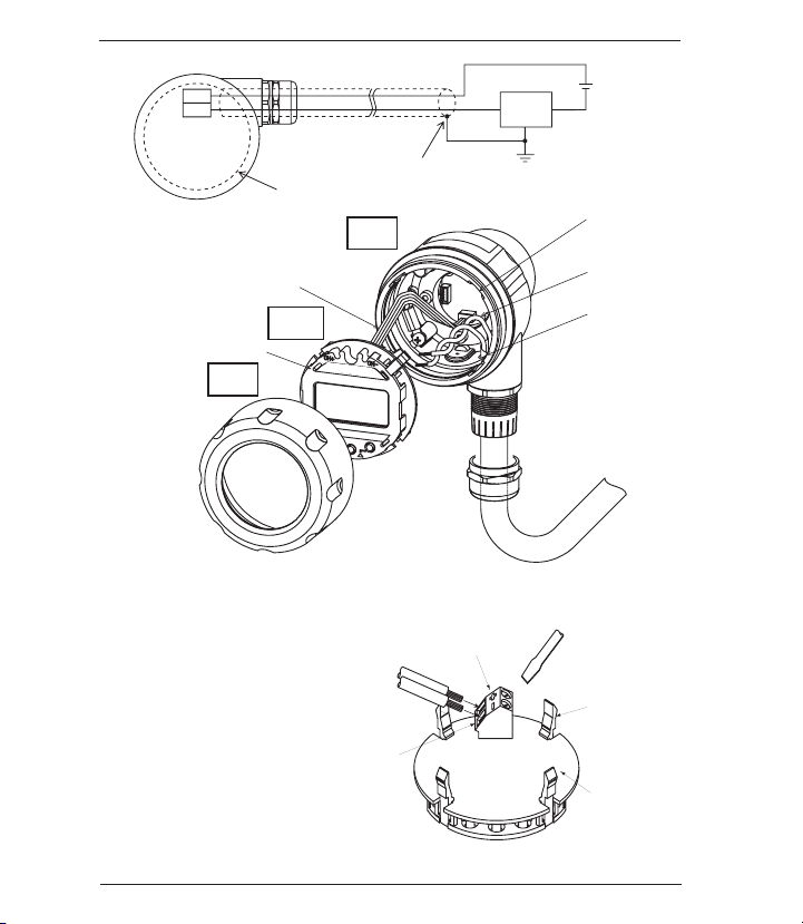
+
−
Terminal box
Display (board)
Shield
Power source
+ −
Receiver
Transmission cable
CASE
DISPLAY
CAP
Inside sensor Line
LCD holder
Notch
Transmission cable
(Twist)
Sheath
Display
Wire terminals
Wire
Turn with a screwdriver
LCD clips (4)
Display board
Power supply
terminal block
P
X
5
2
0
0
• Turn display over to
expose terminal strip,
make positive and
negative connections,
insert wire depth is
equal to recommended
strip length (0.25˝).
11
Page 12
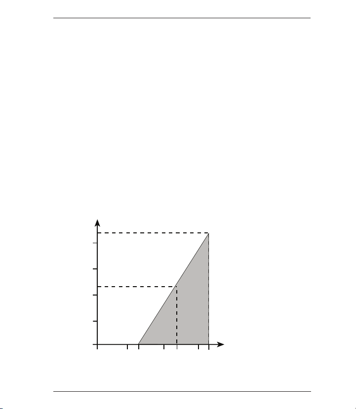
• After completing connections locate retaining clips in the appropri-
1000
750
500
250
0
0 322010
1020
30
Load Limitations 4-20mA Output Only
12 24
545
OPERATING
REGION
Loop Resistance (V)
ate notches and carefully place into the housing. Be sure that internal sensor transmission wire does not cross the power supply lines
just installed.
• If using the Cable Gland be sure to properly tighten sealing grommet
before applying any tension on the cable, the cable gland provides
strain relief and environmental sealing.
• Tighten GC52 cover to maintain environmental rating.
• Connect to power source and receiver and power on to confirm correct wiring (see Section 10 for more detail).
• Power Supply Requirements: Although the 4-20mA signal can travel
over long distances one of the most common problems is inadequate
power at the pressure transmitter due to the voltage drop across the
loop. Be sure to review table below to determine that 12-32V is getting to the pressure transmitter.
12
Page 13

In H2O
Test Terminals
8.8.8.8.8.8.
2
Differential Pressure
Unit Monitor
7
Linear Scaling Mode
5 DOWN key
6 UP key
8 No Function
3 Scaling-Arbitary
Unit Monitor
1 Measured Data
Display
L Total Flow Volume
Display (X1000)
K Total Flow Volume
Display (X100)
4 MODE key
9
Total Flow Volume
Display (X1)
J
Total Flow Volume
Display (X1)
M
CH+
CH–
PX5200-200WUDI
8. DISPLAY FUNCTIONS
DESIGNATION FUNCTION
Measured data
display
Differential
pressure unit
monitor
Scaling;
arbitrary unit
monitor
MODE key
(M)
DOWN key
S
UP key
T
Differential pressure, linear scaling
value are displayed.
When this unit monitor is ON, the
differential pressure (in H
cated on the measured data display.
When this unit monitor is ON, the
scaling value of an arbitrary unit
(linear scaling), is indicated on the
measured data display.
This key is used to switch the setting
mode and the measurement mode
and to change the setting item.
This key is used to change (decrease)and select the set value .
This key is used to change (increase) and select the set value
and to shift from the measurement mode to the zero adjustment mode.
O) is indi-
2
13
DESIGNATION FUNCTION
Linear
scaling
mode
Used to adjust zero/
span values
to 4-20mA
output signal.
No None
function
to
Total flow
volume
display
Page 14

9. MODE CHANGES
8.8.8.8.8.8.
80.0
g[52
• Measurement Mode (Section 11 for further detail) will be entered upon
power-on. Setting Mode (Section 14 for further detail) is entered by
pressing and holding the MODE button for more than 3 seconds. If there
is no button operation for 10 minutes in the setting mode, it will shift back
to the Measurement Mode automatically.
• To go from the Measurement Mode to the Zero Adjustment Mode (Sec-
tion 12 for further detail) press and hold the UP T button for more than
3 seconds.
Power ON
Power on message
(M) key for more than 3 seconds (
Setting mode
(M) key for more than 3 seconds or if there
is no operation for 10 minutes
10. POWER-ON MESSAGE
After the power is turned on, the power-on message is displayed for 6
seconds as shown below and then the display is shifted to the measurement mode (section 11). In addition, the analog output during power-on
message is at the zero point (4mA).
Measurement mode
All lights
two seconds
Differential
pressure range
two seconds
Product
14
▲
) key for more than 3 seconds
Zero adjustment mode
Finish
Page 15

11. MEASUREMENT MODE
The measurement mode includes differential pressure display mode, and
linear (scaling) display mode. For the setting items to
27 , please refer to
the Setting Mode (section14).
11.1 Filter
Set the filter before setting pressure display mode or linear (scaling)
display mode.
The filter is based on the moving average of the pressure data to decrease display “bounce” and to smooth the analog output due to system pressure fluctuations at the user’s discretion.
Five selections: (0, 2, 4, 8, and 16 seconds).
If “0” is selected the filter is not applied.
See Section 14.4 for full menu.
Filter Setting ==> item
11.2 Differential Pressure Display Mode (Re-scaling in “inH
0” units)
2
This mode is used for display and analog output of the actual differential pressure.
(1) Analog output
The analog output can be adjusted as follows; the zero point
(4mA) and the span point (20mA) can each be adjusted from –10
to 110%F.S. (URL)*.
(2) Pressure display
The pressure display has a display span between the zero point
and the span point as determined by the adjustment of zero and
span (see previous paragraph) and can display the range of –5
to 105%F.S.(URL). In addition, the decimal point position of the
pressure display is fixed for each pressure range.
Pressure Unit: in.H
See Section 14.4 for full menu.
O
2
Output zero point and span point setting ==> Setting item ,
*This means that although the zero point is typically set at 0%F.S. (in the case of bi-directional
ranges 0%Span) and the span point is set as 100%F.S., the zero point can be adjusted to the
point where zero (4mA) is 110%F.S. and the span point (20mA) can be adjusted to -10%F.S thus
reversing the output. In addition, through this adjustment zero and span can be adjusted accordingly for elevated tank levels.
15
Page 16

8.00
Setting example 1 : Differential pressure display mode
The setting to use the differential pressure range 0 to 20in.H
and to display the zero point and span point of the analog output as –2
in.H2O and 18 in.H2O respectively is as follows:
In the example the filter (moving average time) is set at 2 seconds, the
differential pressure display and the analog output are based on the
moving average equivalent to the differential pressure data per 100ms
for the past 2 seconds (20 times).
Select the filter of “2 seconds” ==> Setting item
Select the “Differential pressure display mode” ==> Setting item
Set output zero point as “–10.0%F.S.” ==> Setting item
Set output span point as “90.0%F.S.” ==>Setting item
䡵 Display and analog output
Ex. Differential pressure of 8 inH
• Differential pressure display: 8.00(H
• Analog output: 12(mA) in.H
O
2
O)
2
O
2
Differential
O (“W.C.)
2
Pressure Analog
Display Output
O) (mA)
(inH
2
Output span point 18.00 ==> 20
兰兰
8.00 ==> 12
Output zero points –2.000 ==> 4
11.3 Linear Display Mode (Re-scaling in arbitrary user defined units)
This mode is used for display / analog output of the scaling value
where the differential pressure is linearly converted to an arbitrary
physical quantity.
(1) Linear display
By setting the OFFSET to the minimum differential pressure P
and the FULL SCALE to the maximum differential pressure P2,
the linear display indicates the value on the line between the two
points (the maximum display span). The actual linear display
span depends on the setting of the zero point and span point of
the analog output as shown in (2) of the next page. It can display
the range of –5 to 105%F.S. of the linear display span.
1
16
Page 17

Display
Display
Full Scale
Full Scale
(20mA)
(4mA)
Offset
(4mA)
Offset
(20mA)
Differential
Pressure
Differential
Pressure
P
1
(Min.)
P
2
(Max.)
P
1
(Min.)
P
2
(Max.)
• The setting range for the minimum differential pressure P
the maximum differential pressure P2is 0 to 100%F.S. of the differential pressure range, and the maximum differential pressure P
is set from the value which is more than 25%F.S. of the differential
and
1
2
pressure range above the minimum differential pressure P1.
• The setting range for the OFFSET and FULL SCALE values
is –1999 to 1999, and the decimal point can be set arbitrarily. At
this time, the arbitrary unit monitor turns on
See Section 14.4 for full menu.
Min. differential pressure P1and
max. differential pressure P2setting ==> Setting item ,
OFFSET & FULL SCALE setting ==>Setting item , ,
(2) Analog output
The zero point (4mA) and span point (20mA) of analog output can be
set in the range of –10 to 110%F.S. of the maximum display span (between OFFSET and FULL SCALE). The span between the zero point
and the span point in this analog output is the linear display span.
Analog output zero point
and span point setting Setting item ,
As shown in the previous diagram, usually, the OFFSET is set as Output zero point (4mA) and the FULL SCALE is set as Output span point
(20mA), but the OFFSET can be reversed to Output span point
(20mA) and the FULL SCALE can be reversed to Output zero point (4mA).
䡵 Setting example 2 : Linear display mode
17
A level gauge using a differential pressure range of 0 to 200 in.H
the linear display setting to display the OFFSET for minimum 20
in.H2O as 0.0, the FULL SCALE for maximum differential pressure 120
in.H2O as 50.0, the unit as arbitrary unit (m), the zero point (4mA) analog output as 0.0, and the span point (20mA) as 50.0 is as follows:
O,
2
Page 18

8.00
See Section 14.4 for full menu.
For display mode, select “Linear display mode” ==> Setting item
Set min. differential pressure P1 as “20 in.H
Set max. differential pressure P2 as “120 in.H
O” ==>Setting item
2
O” ==> Setting item
2
Set decimal point position of linear display
as “one digit” ==> Setting item
Set OFFSET of linear display as “0.0m” ==> Setting item
Set FULL SCALE of linear display as “50.0m” ==> Setting item
Set output zero point as “0.0%F.S.”
(0.0m) of max. display span* ==> Setting item
Set output span point as “100.0%F.S.”
(50.0m) of max. display span* ==> Setting item
*Maximum display span: OFFSET to FULL SCALE
䡵 Linear display and analog output
Ex. Differential pressure 70 in.H
O
2
• Linear display: 25.0(m)
• Analog output: 12(mA)
(1)
m
Differential Linear Analog
Pressure Display Output
O) (m) (mA)
(in.H
2
120 ==> 50.0 ==> 20 Span Point
兰兰 兰
70 ==> 25.0 ==> 12
20 ==> 0.0 ==> 4 Zero Point
(1) Put the arbitrary unit sticker.
18
Page 19

11.4 Flow Measurement/Square Root Extraction Mode
Square Root Display Mode
Combining the sensing elements (orifice and pitot tube) with this product, the mode is used for the display of the momentary flow rate, integrated volume and for analog output corresponding to the momentary
flow rate.
(1) Momentary flow rate
Maximum display span from zero to the maximum momentary flow
rate. The Momentary flow rate display span depends on the set-
ting of the zero point and span point of the analog output as shown
in (2) analog output. It can display 0 to 105%F.S. of the momentary
flow rate display span. The scaling method can be performed only
by setting the maximum momentary flow rate and then generate
differential pressure using the following square root formula.
Momentary flow rate Dx is expressed by the square root formula
(a), and can be calculated only by measuring the generated differential pressure Px (percent value over the differential pressure
range).
(%)
P
(a)
In addition, the coefficient k is determined by substituting the
maximum momentary flow rate Dm, which is measured from the
formula (a), and the then generated differential pressure Pm into
the formula (b).
(a)
• The differential pressure generated during the maximum momen-
tary flow rate can be set in the range of 25 to 100%F.S. of the differential pressure range.
• The setting range for values of the maximum momentary flow rate
is 0 to 1999. Note: The decimal point can be set arbitrarily.
Setting of max. momentary flow rate and then
generated differential pressure ==> Setting item , ,
Dx= k x
k =
D
P
公
100
m
m
公
00
x
100(%)
19
Page 20

• When the display resolution lowers and the wobbling of momentary
999999
0
0
overflows
clr
flow rate increases in the low flow domain of the differential pressure
flow meter, the domain (below the set value) will be forcedly indicated as zero by means of the low-cut for momentary flow rate.
Moreover, the analog output has a fixed value of 4mA at the zero
point. For setting of low-cut, input the percent value over the maximum
display span. Its range is 0 to 30%F.S. and the decimal point position
can be set up to one digit after decimal point as fixed point.
Setting of low-cut ==> Setting item
(2) Analog output
The zero point (4mA) and span point (20mA) of analog output can
be set in the range of 0 to 110%F.S. of the maximum display span
(0 to maximum momentary flow rate). The span between the zero
point and the span point in this analog output is the momentary
flow rate display span.
(3) Integrated volume
• The units of integrated volume include two standards: Time
factor and flow rate volume factor.
Setting of integrated volume unit ==> Setting item
• The number of digits of integrated volume display is a
maximum of 6 figures (999999); the display will return to 0 once
the maximum reading has been met.
• The zero reset of an integrated volume is executed by pressing S key
for more than 3 seconds and displaying "cLr" (clear) for 2 seconds.
20 , 21
• As backup in case of POWER OFF, the integrated volume value
is stored in the nonvolatile memory for every hour. After power returns, integration starts from the integrated volume value stored in
the memory.
20
Page 21

• Integration is halted during the "FFF" display at the time of
differential pressure range OVER (Refer to paragraph 11.5 (1) ).
• The indicated value which is blinking is integrated during the
"blink" display at the time of momentary flow rate display span
OVER (Refer to paragraph 11.5 (2) ).
(4) Display switching method of momentary flow rate and
integrated volume
Display switching methods of momentary flow rate and integrated
volume include the automatic switching display method to display them by turns at intervals of fixed time (1 to 10 seconds) and
the manual switching display method to change the display by
pressing (M) key.
Selection of display switching method
(automatic or manual) ==> Setting item
22
Setting of display switching time
for automatic ==> Setting item
23
䡵 Setting example 3: Standard unit for square root display mode
In the differential flow meter whose differential pressure generated at
maximum momentary flow rate of 120 is 32IW (80%F.S.) and which
uses a differential pressure range of 0 to 40IW, the scaling setting of
the momentary flow rate of standard unit and the setting of integrated
volume of the standard unit are as follows:
In this case, the low-cut is set as 15%F.S., the display switching
method is set as automatic, and the switching time is set as 5 seconds.
Select the “Square root display mode ==> Setting item
Set the differential pressure at max. momen-
tary flow rate as 32.0IW (80%F.S.) ==> Setting item
Select “1-digit” as decimal point position
of momentary flow rate ==> Setting item
Set the max. momentary flow
rate as “120.0.” ==> Setting item
Set the low-cut as “15.0%F.S.” of
max. display span* ==> Setting item
Set the output zero point as “0.0%F.S.”
(0.0 arbitrary unit of measure) of
max. display span* ==> Setting item
21
Page 22

Set the output span point as “100.0%F.S.”
84.9
270225
(120.0 arbitrary unit of measure) of
max. display span* ==> Setting item
Set time factor selection
(seconds, minutes, hours) ==> Setting item
Select standard “I” as flow rate volume factor ==> Setting item
Select “ti” (automatic) as display
switching method ==> Setting item
Set automatic display switching time
as “5 seconds” ==> Setting item
*Maximum display span: 0 to Maximum momentary flow rate
䡵 Arbitrary unit of square root display and analog
Momentary flow rate display (standard)
Outbreak differential pressure: 16IW Integrated volume display (arbitrary unit)
• Second flow quantity: 84.9 Integrated volume 270225
(Next page reference)
• Analog output: 15.3 mA
Differential Pressure Momentary Flow Rate Unit Analog Output
IW) (mA)
(
32 120 20
|||
16 84.9 15.3
|||
004
It It is alternation
indication for every
five seconds
(Automatically)
Span Point
Zero Point
21
22
23
22
Page 23

120
(Dx)
(Max.)
84.9
0
20
40
60
80 100
Differential Pressure
(%F.S.)
Momentary Flow Rate
(16IW)
(32IW)
䡵 Square Root
The momentary flow rate Dx at a generated differential pressure of 16IW
(40%F.S.) is calculated by the following formula:
The coefficient k is determined by substituting the maximum momentary flow
rate Dm=120 and the then differential pressure Pm=80%F.S.(32IW) into the
formula (b) of the preceding paragraph 11.4 (1).
00
D
k =
Therefore, the momentary flow rate Dx is determined by the formula (a) of
the preceding paragraph 11.4(1).
Dx= kx
P
m
公
100
公
m
P
x
100
120
=
80
公
100
= 134.2
=
134.2
40
公
100
= 84.9
䡵 Setting example 4: Arbitrary unit of square root display mode
Setting of momentary flow rate
In order to set a momentary flow rate to an “arbitrary unit,” the
momentary flow rate unit must be set as the arbitrary unit, and the
maximum momentary flow rate of the arbitrary unit and the then
generated differential pressure must be set.
23
Page 24

Setting of integrated volume
When a momentary flow rate unit is set as an arbitrary unit, the
integrated volume is also an arbitrary unit and the factor of the
two following points must be set:
• Setting of time factor (second, minute, hour)
• Setting of flow factor weight (1, 10, 100, 1000)
In the differential flow meter whose differential pressure generated
at maximum momentary flow rate of 1.000L/s is 16IW (80%F.S.)
and which uses a differential pressure range of 0 to 2.0 IW, the
setting of momentary flow rate of arbitrary unit and the setting of
integrated volume of the arbitrary unit (in order to display 1 per
count) are as follows: In this case, the low-cut is set as 10%F.S.
and the display switching method is set as manual.
Select the “Square root display mode” ==> Setting item
Set the differential pressure at max. momen-
tary flow rate as 16IW (80%F.S.) ==> Setting item
Select “3-digit” as decimal point position
of momentary flow rate ==> Setting item
Set the max. momentary flow rate as “1.000.” ==> Setting item
Set the low-cut as “10.0%F.S.” of max.
display span* ==> Setting item
Set the output zero point as “0.0%F.S.”
0 of max. display span* ==> Setting item
Set the output span point as “100.0%F.S.”
1 of max. display span* ==> Setting item
Select “SEC” (second) as time factor of
integrated volume ==> Setting item
Select “1” as weight of flow factor of
integrated volume ==> Setting item
Select “bt” (manual) as display
switching method ==> Setting item
*Maximum display span: 0 to Maximum momentary flow rate
21
22
24
Page 25

䡵 Square root display and analog
0.868
570616
Momentary flow rate display (arbitrary unit)
Differential pressure: 12IW Integrated volume display (arbitrary unit)
• Momentary flow rate 0.868 Integrated volume: 570616
• Analog output: 17.9 mA
Display alternation
whenever the
(M) key is pushed
(Manual)
Differential Momentary Flow
Pressure Rate Unit Analog Output
(IW) (mA)
16 1.000 20
|||
12 0.868 17.9
|||
004
Span Point
Zero Point
25
Page 26

11.5 Out of Range Display
(1) Range Over display
In the Measurement Mode, if the pressure is below –15% F.S.
(URL) “–FFF” will be displayed, and if it is more than 115%F.S.,
“FFF” will be displayed.
(2) Span Over display
When the user has adjusted the span of the device this case will
apply. The display range in each display mode is –5 to 105%F.S.
of the display span. When this range is exceeded, the value
of –5%F.S. or 105%F.S. will be held (depending upon whether
unit is below or above the span values) in a blinking state.
(3) Analog output
The analog output is linked with the display and is at 3.2mA when
the display span is at or exceeded –5%F.S. and at 20.8mA when
the display span is at or greater than 105%F.S.
䡵 Out of Range Display
Differential pressure mode (Differential pressure range 0 to 20in.H
Pressure display span 20in.H2O)
Span point: 20.0
Zero point: 0.0
• Overage display
O)
2
26
Page 27

• Overage display
-0.050
-fff
fff
1.050
–15%F.S. (–3.0 inH2O) more/less
– 5%F.S. (–1.0 inH
2
O) more/less
115%F.S. (23.0 inH
2
O) more/less
105%F.S. (21.0 inH
2
O) more/less
Adj
e-0
– Normal Message –
– Error Message –
• Span over display
12. ZERO ADJUSTMENT MODE
In the measurement mode, the pressure connection (H, L) is open to the
atmosphere and T key is pressed for more than 3 seconds in order to
shift to zero adjustment mode (refer to section 11) for zero point adjustment of the differential pressure sensor.
• If the zero point adjustment is correctly performed, the message "AdJ"
will be displayed for 2 seconds, and the display will return to the measurement mode.
• If zero point correction is performed when the applied pressure is over
±10%F.S., the error message “E-0” will be displayed for 2 seconds, and
the display will return to the measurement mode without completing the
zero point adjustment.
CAUTION: Only perform the zero point correction when both the
H and L ports are open to the atmosphere. If done incorrectly the
accuracy of the device may be effected.
27
Page 28

13. KEY LOCK
Function Key Manual Indicator
Setting of key lock MODE+$one second LoC
Release of key lock MODE+$one second UnL
Operation during keylock
Function Key Manual Indicator
Zero adjust. mode
Hold value reset
key greater than 3 sec. LoC (Key invalidity)
$
key greater than 3 sec. LoC (Key invalidity)
#
14. SETTING MODE
The setting modes include differential pressure display mode setting, linear
display mode setting, and flow measurement/square root mode setting. In
addition, loop check (refer to section 14.5) can be performed in each
mode setting.
For the setting procedure of each display mode, refer to paragraphs 14.3
and 14.4.
14.1 List of Setting Items for Differential Pressure Display Mode
(Re-scaling in “inH
O” units). Set the filter before setting the differential
2
pressure setting mode. See page 24 for full menu.
No. Setting Item LCD Display Setting Description Setting Range Default*
Filter Selection of 0,2,4,8,16,sec 4
f00002
moving average
time of differential
pressure: 2 (sec)
*The factory default.
28
Page 29

The setting of the following table is the Setting example
1: pressure display mode of Section 11-2. This applies when
re-scaling in “inH
No. Setting Item LCD Display Setting Description Setting Range Default
Display mode
Output zero
(1)
point
Output span
(1)
point
Loop check
(1) For setting of zero point and span point in the analog output, input the percent value over the differential
pressure range.
(2) Regardless of generated differential pressure, the loop check can be changed by arbitrarily linking the pres-
sure display with the analog output using ▲, ▼ key. (Refer to Section 14.3). This example of LCD display
shows the zero point display at the time of loop check start.
14.2 Setting Items for Linear Display Mode (Re-scaling in arbitrary user
(2)
defined units) Set the filter before setting the linear display mode
(Refer to the preceding Section 11.1). The setting of the following table
is the Setting example 2: Linear display mode of Section 11.3.
(Arbitrary unit: m). This applies when re-scalingin arbitrary user
defined units. See Section 14.4 for full menu.
0” units. See Section 14.4 for full menu.
2
Selection of differ-
-
n00non
a0-10.0
a0-90.0
[0-10.0
-
ential pressure display mode: non
Differential pressure of analog
output zero point
4mA: –10.0(%F.S.)
Differential
pressure of analog
output span point
(20mA):
90.0(%F.S.)
Arbitrary change of
differential pressure display and
analog output:
–10.00 (psi).)
non: Differential
pressure display
mode
Lin: Linear display
mode
Differential pressure range:
–10 to 110%F.S.
Differential
pressure range:
–10 to 110%F.S.
Display: Differential
pressure display
span; Analog
output: 4 to 20mA
non
0.0
100.0
0.0
(4.00
mA)
29
Page 30

No Setting Item LCD Display Setting Description Setting Range Default
Display mode
Min. differential pressure
Max. differential pressure
Decimal point
position
OFFSET
-
n00l0n
(1)
p0 -20
(1)
p0-120
d0-001
d0-00.0
FULL SCALE
d0-50.0
Output zero
(2)
point
Output span
point
Loop check
(2)
a0-50.0
a0100.0
(3)
[0-50.0
(1) The decimal point position is fixed for each differential pressure range. (Refer to section 10, Power-on Message).
The max. differential pressure can be set from the value which is 25%F.S above the minimum differential pressure.
The values under 25%F.S. cannot be increased or decreased by T, S key.
(2) For setting zero point and span point of the analog output, input the percent value over the maximum display span
(between OFFSET and FULL SCALE). Its decimal point position can be set up to one digit after the decimal point
(xx.x).
(3) Regardless of whether pressure is applied or not, the loop check can be activated which links the display and the
output allowing the operator to arbitrarily adjust the output to check the system, troubleshoot etc (using the T, S
keys), ref section 14.4. This example shows the display set to the span point.
Selection of linear
display mode: Lin
-
Min. differential
pressure corresponding to OFF-
:20.0(inH
SET
Max. differential
pressure corresponding to FULL
:120inH
SCALE
Display after decimal point Number
of digits:1(digit)
OFFSET corresponding min. differential
pressure
FULL SCALE corresponding to max.
differential pres-
:50.0 (m)
sure
Analog output zero
point : (4mA): 0.0
(%F.S.)
Analog output span
point : (20mA):
100.0 (%F.S.)
Arbitrary change of
linear display and
analog output:
50.0 (m), 20mA
30
2
O)
2
: 0.0 (m)
non: Differential
pressure display
mode; Lin: Linear
display mode
Differential pressure range:
0 to 75%F.S.
O)
Differential
pressure range:
25 to 100%F.S.
0,1,2,3 digit
–1999 to 1999
–1999 to 1999
Max. display span:
–10 to 110%F.S.
Max. display span:
–10 to 110%F.S.
Display: Linear display span; Analog
output: 4 to 20mA
non
0.0
100.0
0
0
1000
0.0
100.0
0
(4.0mA)
Page 31

14.3 Flow Measurement/Square Root Extraction Mode
No. Setting Item LCD Display Setting Description Setting Range Default
Display mode
Maximum
differential
selection
Flow rate deci-
mal pt. position
Max. momen-
tary flow
Low cut
Output zero
point
Output span
point
Time factor
Flow rate vol-
21
ume factor
Display
switch set-
22
ting
Switch time
interval
23
Loop check
24
(1) In the setting of a differential pressure the decimal point position is fixed for each differential pressure range. (Refer
to paragraph 12, Power-on Message). The max. differential pressure can be set from the value which is 25%F.S of
the differential pressure range above the minimum differential pressure.The values under 25%F.S. cannot be increased or decreased by T, S key.
(2) For setting zero point and span point of the analog output, input the percent value over the maximum display span
(between OFFSET and FULL SCALE). Its decimal point position can be set up to one digit after the decimal point (xx.x).
(3) Regardless of generated differential pressure or low-cut, the loop check can be changed arbitrarily linking the mo-
mentary flow rate display with the analog output using the T, S keys. (Refer to 14.5.) This example of LCD display
shows the display set to span point.
n~ roT
p. 400
1
D 0
D 1000
l 0.0
2
A 0.0
2
A100.0
U SE[
U 1
s bT
T 5
3
c 0.0
Selection for flow measurement/ square root extraction
mode
Maximum differential pressure relating to the flow rate
Displays of value after decimal point, # of digits
Max. momentary of flow
using arbitrary units
Forces display and output to
zero
Momentary flow rate of analog output zero point (4mA):
100.0% F.S.
Momentary flow rate of ana-
log output zero point
(20mA): 100.0% F.S.
Measurement of max. momentary flow rate over time
selected
Flow rate x time selected 1,10,100,1000
Selection of display switching
method of momentary flow
rate and integrated volume
Selection for ti: automatic
Displays switching time interval in seconds
Output check using arbitrary
value – displays pressure
correlating to the 4 to 20mA
signal
non: Differential pressure
display mode Lin: Linear
display mode Rot: Square
root display mode
25 to 100% F.S. of sensor
range
0,1,2,3 digit
0 to 1999
0.0 to 30.0% F.S. of max.
display span
–10 to 100% F.S. of max.
display span
–10 to 100% F.S. of max.
display span
Seconds, minutes or hours
ti = automatic
bt = manual
1 to 10 seconds (10 stage)
Display: momentary flow
rate display span
Analog output: 4 to 20mA
0.0 to 100.0%
non
100.0%
of sensor
range
0
1000
0.0
0.0
100.0
Sec
1
bt
5
0
(4.0mA)
31
Page 32

u
M
u
M
u
M
u
M
u
M
u
M
u
M
u
M
u
M
u
M
u
M
u
M
u
M
u
M
u
M
u
M
a
b
e
c
d
f
g
h
i
j
k
l
u 6.00
f 2
n non
n l n
a 10.0
a 90.0
[ 1.00[ 1.00
p 20.0
p 120.0
d 1
d 0.0
d 50.0
a 0.0
a 100.0
[ 50.0
-
`
-
-
Linear display
mode setting
Differential pressure
display mode setting
Differential
pressure
display mode
Output span
point pressure
Output zero
point pressure
Loop check
(zero point)
V
ersion display
Filter
Linear display
mode
Min. pressure
(Re-scaling in
“inH
2
O” units)
(Re-scaling in arbitrary
user defined units)
Max. pressure
Decimal point
position
OFFSET
Full scale
Output zero
point
Output span
point
Loop check
(span point)
B
asic key operation
The setting item is changed by
u
M key.
The set value is changed or selected by
▲ key or ▼ key. When changing the value,
it is increased or decreased by pressing
▲ key or ▼ key, respectively.
(Refer to next page)
key for more
t
han 3 seconds
Setting Mode
Measurement Mode
m
Flow
Measurement
Mode
See
Page 6
14.4 Setting Procedure (Setting Examples from 14.1, 14.2)
32
See
Section
14.4
Page 33

u
M
u
M
u
M
u
M
u
M
N ROT
d 0 d i d Z d 3
a 100.0
L 0.0
P. 4.00
a 0.0
U SE1
U SE( U houU n~In
U 10 U 100 U 1000
Flow Measurement Mode
(Square Root Extraction Settings)
Refer to
P
age 5
b Flow Measurement / Square Root
Extraction Mode
n Maximum Differential
Selection (Exam ft:4in)
o Flow Rate
Decimal Point
Position
5 Bt
u22 Display Switch
Setting
u
23 Switch Time
Interval
u
24 Loop Check
Returns to
Setting Mode
See Page 5
q Low Cut
s Output Span Point
t Time Factor
u
M
u
M
u
M
u
M
u
M
u
M
u
M
u
M
p Maximum Momentry
Flow
C
D
C
D
C
D
C
D
C
D
t 5
c 0.0
u21 Flow Rate
Volume Factor
C
D
C
D
C
D
C
D
u
M
r Output Zero Point
u22
5 t;
D 1000
33
Page 34

Check
Terminals
14.5 Loop Check
In each display mode, regardless of applied pressure, the loop check can
be changed by arbitrarily linking the display with the analog output using
the key operation. The display will show representative pressure readings
correlating to the 4-20mA signal.
䡲 Loop check method
(1) Remove the lid of this product.
(2) Shift to either the differential pressure, linear display or flow
measurement modes. (See Section 14). Use (M) button to scroll to
Loop Check function as indicated within Section 14.1, 14.2 or 14.3 respectively. The display and output (4mA) are at the zero point when
loop check starts.
(3) If the T is pressed, the display will increase along with the
output. By pressing S key, decrease will occur. Release the
key at the desired indication. For example, if the key is released at
25.0m, the display will stop and be held at analog output 12mA corresponding to the indication, ref. example from section 14.2
䡲 Analog Output Check Terminals
When the front cover is removed, the analog output check terminals
(pad: CH+, CH–) are visible at the upper part of the display substrate.
The analog output can be checked during measurement mode or loop
check by applying a probe, such as a tester for current measurement,
onto the check terminal of the substrate, as shown in the following figure.
In addition, receivers are not affected by the tester's probes.
Loop check / linear display
PX5100
34
Page 35

Dimension Drawings
Dimensions in inches
1.0
4.49
3.62
2.91
2.28
4.72
5.12
1.97
2.36
.69
2 x Ø .06
Drain
4 x Ø .22
P
anel Mounting Holes
Bracket t = .08
Ø 2.56
.42
2.07
Drain Outlet
Equalizing Valve
High Pressure Port
1/4 NPT female
.82
1.42
Electrical Connection PG 13.5
threaded housing, factory installed
options include cable gland or
1/2 FNPT conduit connection
inH2O
G
C52
15. DIMENSION DRAWINGS
PX5100
35
Page 36

16. MAINTENANCE AND WARRANTY
䡲 Periodic inspection
Depending upon the type of use periodic inspection is recommeded
at least once a year. Please refer to the following items for periodic
inspection.
(1) Appearance
(2) Display/output check via appropriate pressure standard
(3) Display/output check via Loop Check
(2)
䡲 CAUTION
• Avoid electrostatic charging. When cleaning this product, please use
a soft, damp, cloth.
• Do not use thinner, etc. which may cause deterioration and failure.
䡲 Product warranty
Except as otherwise provided, the product warranty of this product is
as follows:
Period: 12 months after delivery
Warrantable defects: Defects resulting from the design and manufac-
ture of our company, the quality of the material, etc.
Implementation of warranty: This warranty will be completed by substi-
tution or repair of the product concerned.
We will not take responsibility for consequential damages caused by
product defects.
• If you have any questions about this document, please contact the
sales office or distributor nearest you.
• This document is subject to change without notice due to upgrade etc.
(1) If zero correction is required refer to section 12.
(2) Loop check, see section 14.5.
(1)
36
Page 37

373839
Page 38

Page 39

OMEG A ENGI NEERING, INC. warra nts this unit to be f ree of defects in mate ria ls and
WARRANTY/DISCLAIMER
workmanship for a period of 13 months from date of purchase. OMEGA’s WARRANTY adds an
additional one (1) month grace period to the normal one (1) year product warranty to cover
h
andling and shipping time. This ensures that OMEGA’s customers receive maximum coverage
on each product.
If the unit malfunctions, it must be returned to the factory for evaluation. OMEGA’s Customer
Service Department will issue an Authorized Return (AR) number immediately upon phone or
written request. Upon examination by OMEGA, if the unit is found to be defective, it will be
repaired or replaced at no charge. OMEGA’s WARRANTY does not apply to defects resulting
from any actio n of the purchaser, includ ing but not limited to misha ndling, impr ope r
interfacing, operation outside of design limits, improper repair, or unauthorized modification.
This WARRANTY is VOID if the unit shows evidence of having been tampered with or shows
evidence of having been damaged as a result of excessive corrosion; or current, heat, moisture
or vibration; improper specification; misapplication; misuse or other operating conditions
outside of OMEGA’s control. Components in which wear is not warranted, include but are not
limited to contact points, fuses, and triacs.
OMEGA is pleased to offer suggestions on the use of its various products. However,
OMEGA neither assumes responsibility for any omissions or errors nor assumes
liability for any damages that result from the use of its products in accordance with
information provided by OMEGA, either verbal or written. OMEGA warrants only
that the par ts manufactured by the company wil l be as specified and free of
defects. OMEGA MAKES NO OTHER WARRANTIES OR REPRESENTATIONS OF ANY
KIND WHATSOEVER, EXPRESSED OR IMPLIED, EXCEPT THAT OF TITLE, AND ALL
IMPLIED WARRANTIES INCLUDING ANY WARRANTY OF MERCHANTABILITY AND
FITNESS FOR A PARTICULAR PURPOSE ARE HEREBY DISCLAIMED. LIMITATION OF
LIABILITY: The remedies of purchaser set forth herein are exclusive, and the total
liability of OMEGA with respect to this order, whether based on contract, warranty,
negligence, indemnification, strict liabil ity or otherwise, shal l not exceed the
purchase price of the component upon which liability is based. In no event shall
OMEGA be liable for consequential, incidental or special damages.
CONDITIONS: Equipment sold by OMEGA is not intended to be used, nor shall it be used: (1)
as a “Basic Component” under 10 CFR 21 (NRC), used in or with any nuclear installation or
activity; or (2) in medical applications or used on humans. Should any Product(s) be used in or
with any nuclear installation or activity, medical application, used on humans, or misused in
any way, OMEGA assumes no responsibility as set forth in our basic WARRANTY/ DISCLAIMER
language, and, additionally, purchaser will indemnify OMEGA and hold OMEGA harmless from
any liability or damage whatsoever arising out of the use of the Product(s) in such a manner.
Direct all warranty and repair requests/inquiries to the OMEGA Customer Service Department.
BEFOR E R ETURNING ANY PRO DUCT (S) TO OMEGA, PU RCHASER MU ST OBTAIN AN
AUTHORIZED RETURN (AR) NUMBER FROM OMEGA’S CUSTOMER SERVICE DEPARTMENT
(IN ORDER TO AVOID PROCESSING DELAYS). The assigned AR number should then be marked
on the outside of the return package and on any correspondence.
The purchaser is responsible for shipping charges, freight, insurance and proper packaging to
prevent breakage in transit.
FOR WARRANTY
the following information available BEFORE
contacting OMEGA:
1. Purchase Order number under which
the product was PURCHASED,
2. Model and serial number of the product
under warranty, and
3. Repair instructions and/or specific
problems relative to the product.
OMEGA’s policy is to mak e running changes, not model changes, wheneve r an improvem ent is possi ble.
This affords our customers the latest in technology and engineering.
OMEGA is a registered trademark of OMEGA ENGINEERING, INC.
© Copyright 2009 OMEGA ENGINEERING, INC. All rights reserved. This document may not be copied, photocopied, re-
produced, translated, or reduced to any electronic medium or machine-readable form, in whole or in part, without the
prior written consent of OMEGA ENGINEERING, INC.
RETURN REQUESTS/INQUIRIES
RETURNS, please have
FOR NON-WARRANTY REPAIRS,
OMEGA for current repair charges. Have the
following information available BEFORE
contacting OMEGA:
1. Purchase Order number to cover the
COST of the repair,
2. Model and serial number of theproduct, and
3. Repair instructions and/or specific problems
relative to the product.
consult
Page 40

Where Do I Find Everything I Need for
Process Measurement and Control?
OMEGA…Of Course!
Shop online at omega.com
TEMPERATURE
䡺⻬
Thermocouple, RTD & Thermistor Probes, Connectors, Panels & Assemblies
䡺⻬
Wire: Thermocouple, RTD & Thermistor
䡺⻬
Calibrators & Ice Point References
䡺⻬
Recorders, Controllers & Process Monitors
䡺⻬
Infrared Pyrometers
PRESSURE, STRAIN AND FORCE
䡺⻬
Transducers & Strain Gages
䡺⻬
Load Cells & Pressure Gages
䡺⻬
Displacement Transducers
䡺⻬
Instrumentation & Accessories
FLOW/LEVEL
䡺⻬
Rotameters, Gas Mass Flowmeters & Flow Computers
䡺⻬
Air Velocity Indicators
䡺⻬
Turbine/Paddlewheel Systems
䡺⻬
Totalizers & Batch Controllers
pH/CONDUCTIVITY
䡺⻬
pH Electrodes, Testers & Accessories
䡺⻬
Benchtop/Laboratory Meters
䡺⻬
Controllers, Calibrators, Simulators & Pumps
䡺⻬
Industrial pH & Conductivity Equipment
DATA ACQUISITION
䡺⻬
Data Acquisition & Engineering Software
䡺⻬
Communications-Based Acquisition Systems
䡺⻬
Plug-in Cards for Apple, IBM & Compatibles
䡺⻬
Datalogging Systems
䡺⻬
Recorders, Printers & Plotters
HEATERS
䡺⻬
Heating Cable
䡺⻬
Cartridge & Strip Heaters
䡺⻬
Immersion & Band Heaters
䡺⻬
Flexible Heaters
䡺⻬
Laboratory Heaters
ENVIRONMENTAL
MONITORING AND CONTROL
䡺⻬
Metering & Control Instrumentation
䡺⻬
Refractometers
䡺⻬
Pumps & Tubing
䡺⻬
Air, Soil & Water Monitors
䡺⻬
Industrial Water & Wastewater Treatment
䡺⻬
pH, Conductivity & Dissolved Oxygen Instruments
40
SM
M5109/0212
 Loading...