

Page 1
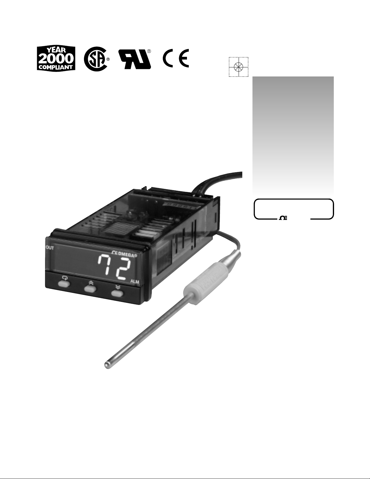
CN491A SERIES
1/32 DIN Temperature/Process Contr ollers
omega.com
http://www.omega.com
e-mail: info@omega.com
User ’s Guide
omega.com
OMEGA
®
®
Page 2

omega.com
OMEGAnet®On-Line Service Internet e-mail
http://www.omega.com info@omega.com
It is the policy of OMEGA to comply with all worldwide safety and EMC/EMI regulations that apply. OMEGA is
constantly pursuing certification of its products to the European New Approach Directives. OMEGA will add
the CE mark to every appropriate device upon certification.
The information contained in this document is believed to be correct, but OMEGA Engineering, Inc. accepts
no liability for any errors it contains, and reserves the right to alter specifications without notice.
WARNING: These products are not designed for use in, and should not be used for, patient-connected applications.
Benelux:
Postbus 8034, 1180 LAAmstelveen
The Netherlands
Tel: (31) 20 6418405 FAX: (31) 20 6434643
Toll Free in Benelux: 0800 0993344
e-mail: nl@omega.com
Czech Republic:
ul. Rude armady 1868, 733 01 Karvina-Hranice
Tel: 420 (69) 6311899 FAX: 420 (69) 6311114
Toll Free: 0800-1-66342
e-mail: czech@omega.com
France:
9, rue Denis Papin, 78190 Trappes
Tel: (33) 130-621-400 FAX: (33) 130-699-120
Toll Free in France: 0800-4-06342
e-mail: france@omega.com
Servicing Europe:
USA and Canada:
Sales Service: 1-800-826-6342 / 1-800-TC-OMEGA
SM
Customer Service: 1-800-622-2378 / 1-800-622-BEST
SM
Engineering Service: 1-800-872-9436 / 1-800-USAWHENSMTELEX: 996404 EASYLINK: 62968934
CABLE: OMEGA
USA: ISO 9001 Cer
tified
One Omega Drive, Box 4047
Stamford, CT 06907-0047
Tel: (203) 359-1660
FAX: (203) 359-7700
e-mail: info@omega.com
Servicing North America:
For immediate technical or application assistance:
Mexico and Latin America:
Tel: (95) 800-826-6342
FAX: (95) 203-359-7807
En Espan~ol: (95) 203-359-7803
e-mail: espanol@omega.com
Germany/Austria:
Daimlerstrasse 26, D-75392
Deckenpfronn, Germany
Tel: 49 (07056) 3017 FAX: 49 (07056) 8540
Toll Free in Germany: 0130 11 21 66
e-mail: info@omega.de
United Kingdom: ISO 9002 Cer
tified
One Omega Drive
River Bend Technology Centre
Northbank, Irlam
Manchester, M44 5EX, England
Tel: 44 (161) 777-6611
FAX: 44 (161) 777-6622
Toll Free in the United Kingdom: 0800-488-488
e-mail: info@omega.co.uk
Canada:
976 Bergar
Laval (Quebec) H7L 5A1
Tel: (514) 856-6928
FAX: (514) 856-6886
e-mail: info@omega.ca
OMEGA
®
®
Page 3

1
TABLE OF CONTENTS
Introduction . . . . . . . . . . . . . . . . . . . . . . . . . . . . . . . . . . . . . . . . . . .2
Fuzzy Logic . . . . . . . . . . . . . . . . . . . . . . . . . . . . . . . . . . . . . . . . . . . .2
Specifications . . . . . . . . . . . . . . . . . . . . . . . . . . . . . . . . . . . . . . . . . .4
Input Range . . . . . . . . . . . . . . . . . . . . . . . . . . . . . . . . . . . . . . . . . . .5
Model Configuration . . . . . . . . . . . . . . . . . . . . . . . . . . . . . . . . . . . .6
Installation . . . . . . . . . . . . . . . . . . . . . . . . . . . . . . . . . . . . . . . . . . . .7
Wiring & Mounting . . . . . . . . . . . . . . . . . . . . . . . . . . . . . . . . . . . . .7
Negotiating the menu . . . . . . . . . . . . . . . . . . . . . . . . . . . . . . . . . .11
Learning the parameters . . . . . . . . . . . . . . . . . . . . . . . . . . . . . . . .12
Primary Program Menu . . . . . . . . . . . . . . . . . . . . . . . . . . . . . . . . .16
Changing Setpoint . . . . . . . . . . . . . . . . . . . . . . . . . . . . . . . . . . . . .17
Begin Controlling . . . . . . . . . . . . . . . . . . . . . . . . . . . . . . . . . . . . . .17
Flow Chart of Parameters . . . . . . . . . . . . . . . . . . . . . . . . . . . . . . .18
Auto-tuning . . . . . . . . . . . . . . . . . . . . . . . . . . . . . . . . . . . . . . . . . . .20
Alarms . . . . . . . . . . . . . . . . . . . . . . . . . . . . . . . . . . . . . . . . . . . . . . .21
Setting Alarms . . . . . . . . . . . . . . . . . . . . . . . . . . . . . . . . . . . . . . . .23
Scaling Analog Inputs/Setting Setpoint Limits . . . . . . . . . . . . . .24
Ramp Function . . . . . . . . . . . . . . . . . . . . . . . . . . . . . . . . . . . . . . . .26
Ramp & Soak/Dwell Function . . . . . . . . . . . . . . . . . . . . . . . . . . . .27
Tool Program Menu . . . . . . . . . . . . . . . . . . . . . . . . . . . . . . . . . . . .29
Flow Chart of Tool Programs . . . . . . . . . . . . . . . . . . . . . . . . . . . . .30
Manual Control . . . . . . . . . . . . . . . . . . . . . . . . . . . . . . . . . . . . . . . .32
Programmable Control Action . . . . . . . . . . . . . . . . . . . . . . . . . . .33
Cooling Control . . . . . . . . . . . . . . . . . . . . . . . . . . . . . . . . . . . . . . . .34
Configurable Menus . . . . . . . . . . . . . . . . . . . . . . . . . . . . . . . . . . . .35
Locking Menus . . . . . . . . . . . . . . . . . . . . . . . . . . . . . . . . . . . . . . . .37
Error Messages . . . . . . . . . . . . . . . . . . . . . . . . . . . . . . . . . . . . . . .38
1
Page 4

2
INTRODUCTION
General Description
The CN491A is a fully programmable, microprocessor-based
temperature/process controller. It offers superior control with 200
msec sampling rate and by using fuzzy logic to enhance its P, I and
D parameters. The 4-digit 0.4” red LED display offers excellent
visibility on a unit that is 1/32 DIN in size.
The CN491A is available with either 20-32V AC/DC or 90-264V AC
power supply. This is a single universal input unit that will accept
8 different thermocouple types, Pt100 RTDs, and a variety of linear
mA and VDC signals. The wide range of options for the two available outputs include relays, SSR drives, 4-20mA, 0-20mA, or
0-10VDC. Output #1 can be used in either a direct or reverse
action control situation with a programmable ramp rate. Output #2
can be used as a control output, as an alarm, or as a dwell timer.
Optional features include 2-wire RS-485 serial communications
with Windows 95
™
-based software, and Analog Retransmission of
process variable, setpoint variable or the percentage of control
output, as a 0-20 mA/4-20 mA DC signal.
The communications software package, CN491A-SOFT, offers
excellent graphics, bar and trend displays, and supports easy-touse database control and back-up capability.
FUZZY LOGIC
The function of Fuzzy Logic is to adjust the PID parameters
internally in order to make the control output more flexible and
adaptive to the process. One of the best analogies would compare Fuzzy Logic to the abilities of a good driver. The driver is
2
Page 5
33
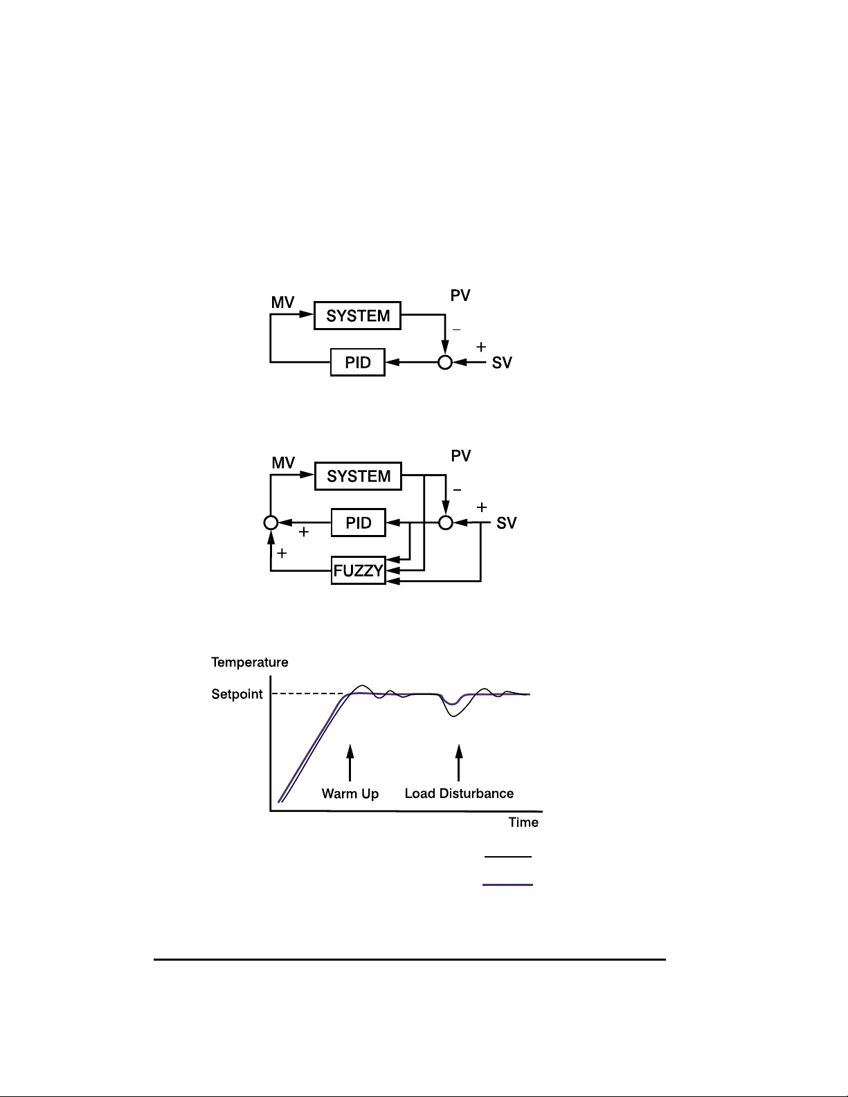
Figure 1. PID only
Figure 2. PID with fuzzy logic
Figure 3. PID vs. PID and fuzzy logic
PID control with proper tuning
PID + Fuzzy control
able to control a car well at a variety of speeds and under varying
circumstances by using knowledge gained through previous
experience.
Fuzzy Logic combined with PID control has been proven to be an
efficient method to improve control stability. This is illustrated in
figure 3.
Page 6

44
SPECIFICATIONS
INPUT
Thermocouple(T/C): Type J,K,T,E,B,R,S,N
RTD: Pt100 ohm RTD
(DIN 43760/BS 1904 or JIS)
Linear: Scalable. Refer to table on p.5
Range: User configurable, refer to table on p.5
Accuracy: Refer to table on p.5
Cold-Junction Compensation: 0.1°C / °C ambient (typical)
External Resistance: 100 ohm max.(for thermocouple)
Normal Mode Rejection: 60dB
Common Mode Rejection: 120dB
Sample Rate: 200 msec
CONTROL
Proportional Band: 0-360°F, 0-200°C, 0-3600 Process Units
Reset (Integral): 0-3600 seconds
Rate (derivative): 0-1000 seconds
Ramp rate: 0-55.55°C/min, 0-99.99°F/min,
0-99.99 Process Units(P.U.)/min
Dwell: 0-9999 minutes
Hysteresis: 0.1-11.0°C, 0.1-19.9°F, 0.1-199 P.U.
Cycle Time: 0-99 seconds
Control Action: Direct (cooling) and reverse(heating)
OUTPUT
Relay: 3A/240 VAC (resistive)
DC pulse: 24 VDC/20 mA max.
4 to 20 mA: Linear, max. load 500 ohms
0 to 20 mA: Linear, max. load 500 ohms
0 to 10 V: Linear, min. input impedance 500K ohms
INDICATION
Process Display: 0.4” red LED, 4 digits
Status Indicator: Control output and alarm
Page 7

55
POWER
Rating: 90-264VAC nominal, 264V excursion (max)
50/60Hz or 20-32V AC/DC
Consumption: Less than 5VA
ENVIRONMENTAL & PHYSICAL
Safety: CE & CSA Approved, & UL Recognized
Protection: NEMA 4X (indoor use), IP65
Operating Temperature: -10 to 50°C (14 to 122°F)
Humidity: 0 to 90%RH (non-condensing)
Insulation: 20 Mohm min. (500 VDC)
Breakdown: AC2000V. 50/60Hz. 1 minute
Vibration: 10-55Hz. amplitude 1mm
Shock: 200 m/s
2
(20g)
Weight: 110 grams
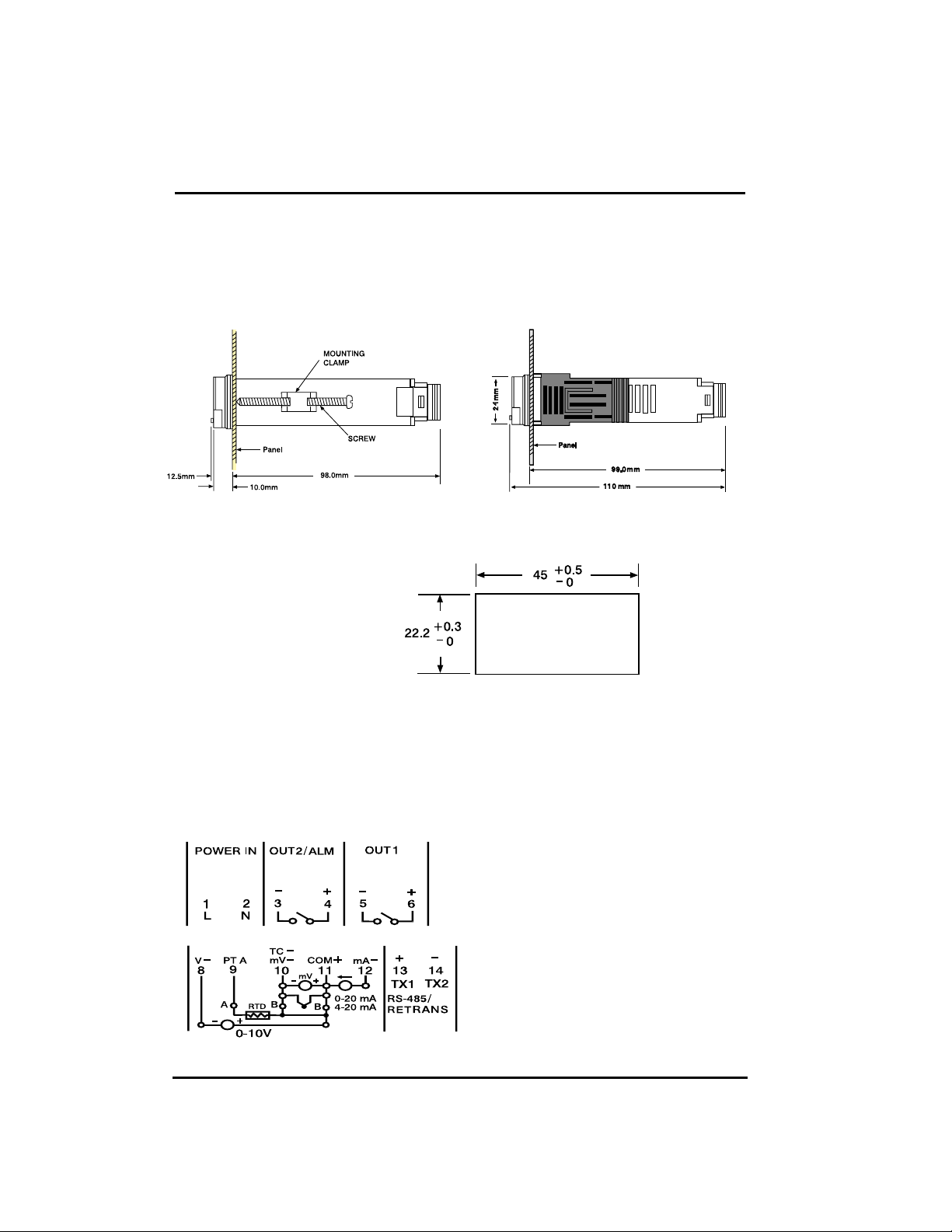
Dimension: 24(H) x 48(W) x 99mm (depth behind panel)
Panel cutout: 22.2mm(H) (+.3/-0) 45 mm(W) (+.5/-0)
RANGE AND ACCURACY OF INPUTS
SENSOR INPUT TYPE RANGE (°F) RANGE (°C) ACCURACY
J Iron-Constantan -58 to 1830 -50 to 999 ±3.6°F/±2°C
K CHROMEGA−
ALOMEGA
-58 to 2500 -50 to 1370 ±3.6°F/±2°C
T Copper-Constantan -454 to 752 -270 to 400 ±3.6°F/±2°C
E CHROMEGA-Constantan -58 to 1382 -50 to 750 ±3.6°F/±2°C
B Pt30%Rh/Pt6%Rh 572 to 3272 300 to 1800 ±3.6°F/±2°C
R Pt13%Rh/Pt 32 to 3182 0 to 1750 ±3.6°F/±2°C
S Pt10%Rh/Pt 32 to 3182 0 to 1750 ±3.6°F/±2°C
N Nicrosil-Nisil -58 to 2372 -50 to 1300 ±3.6°F/±2°C
RTD Pt100 ohm (DIN) -328 to 842 -200 to 450 ±0.72°F/±0.4°C
RTD Pt100ohm (JIS) -328 to 842 -200 to 450 ±0.72°F/±0.4°C
LINEAR INPUTS (All scalable)
Input type Range Accuracy
4-20 mA, 0-20 mA, 0-1V, 0-5V, 1-5V, 0-10V -1400 to 9400 ±0.05% FS
Page 8

66
CN491A MODEL CONFIGURATION
Model No Description
CN491A-R1 Relay Output
CN491A-D1 DC Pulse Output
CN491A-F1A 4-20mA Output
CN491A-F1B 0-20mA Output
CN491A-V1 0-10V Output
SECOND OUTPUT/ALARM
Suffix Description
-R2 Relay
-D2 DC pulse
-F2A 4-20mA
-F2B 0-20mA
-V2 0-10V
AUXILIARY OPTIONS
Suffix Description
-C4 RS-485 Communications
-PVSV 0-20mA/4-20mA retransmission
OPTIONAL POWER SUPPLY
Suffix Description
-LV 20-32V AC/DC
Page 9
7
INSTALLATION
MOUNTING
Install mounting clamp(s). Gently tighten clamp until the controller
fits snugly against the front panel.
Make panel cutout as
shown in figure
WIRING
The following connections for outputs and inputs are provided on
the wiring diagram located at the rear of the housing:
7
NEMA brackets Collar bracket
1/32 DIN
Rear Terminal Connections
Page 10
88
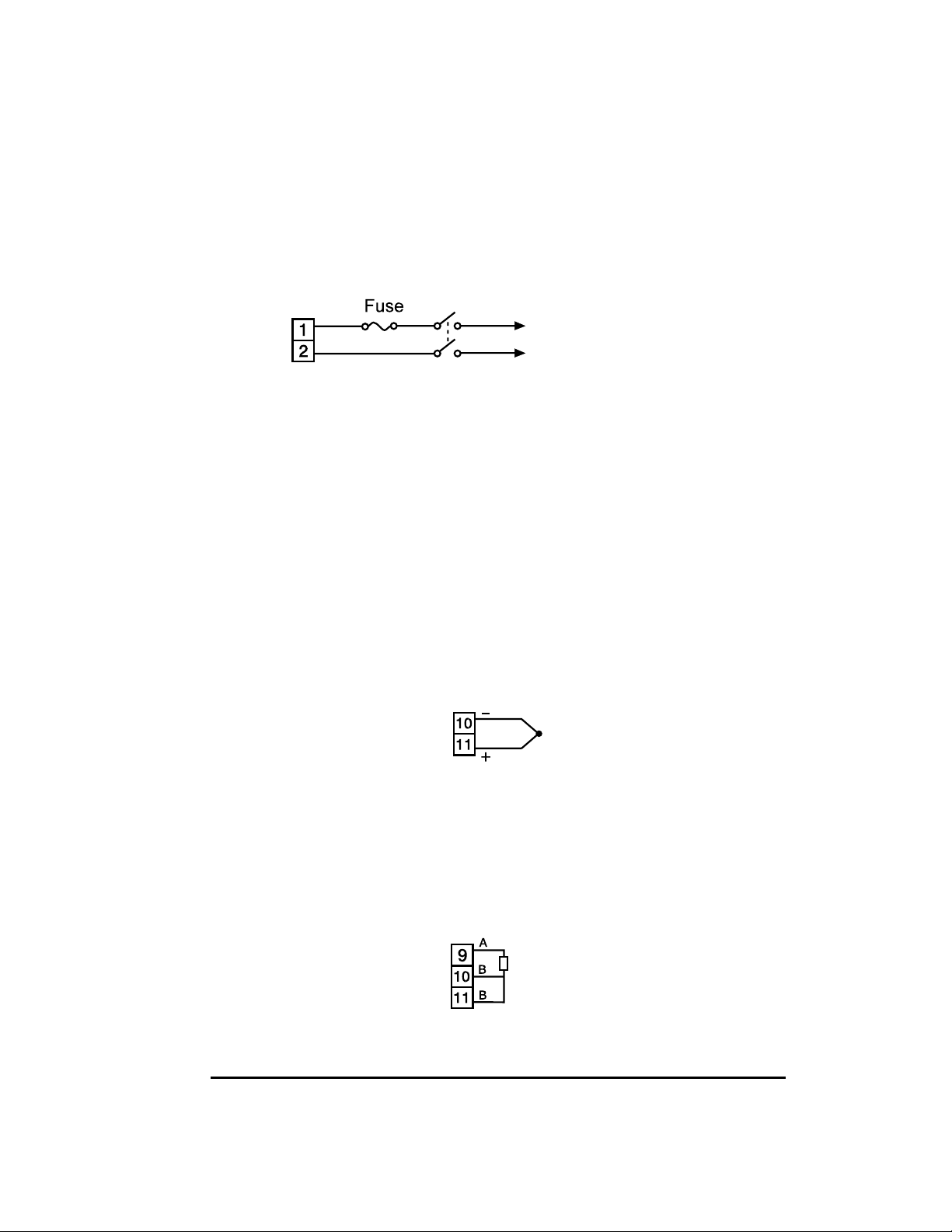
POWER SUPPLY
The controller is supplied to operate on either 90-264V AC or 2032V AC/DC. Check that the supply voltage corresponds to that
indicated on the product label before connecting power to the
controllers.
This equipment is designed for installation in an enclosure which
provides adequate protection against electric shock. The enclosure must be connected to earth ground.
THERMOCOUPLE INPUT
Thermocouple input connections are shown in the illustration
below. The thermocouple extension wire must be of proper type
and gauge, and should be run in a conduit, separate from any
power wiring. The resistance of the entire run should not exceed
100Ω.
Pt100 Ohm RTD INPUT
RTD connections are shown in the illustration below with the
compensating lead connected to terminal 11. For two-wire
RTD inputs, terminals 10 and 11 should be linked.
Power Supply Connections
Thermocouple Input Connections
RTD input Connections
Pt100
90~264V AC or
20-32V AC/DC
L
N
1A
Page 11
9
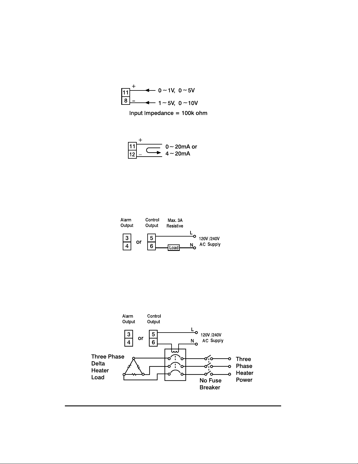
DC LINEAR INPUT
DC linear voltage and current input connections are shown below.
RELAY OUTPUT DIRECT DRIVE
The illustration below shows connections for using the internal
relay to drive a small load. The current should not exceed 3 amps.
RELAY OUTPUT CONTACTOR DRIVE
The illustration below shows connections for using an external
relay to drive heavier loads.
9
VDC
mADC
Relay Contactor Drive Connections
Relay Direct Drive Connections
Page 12
10
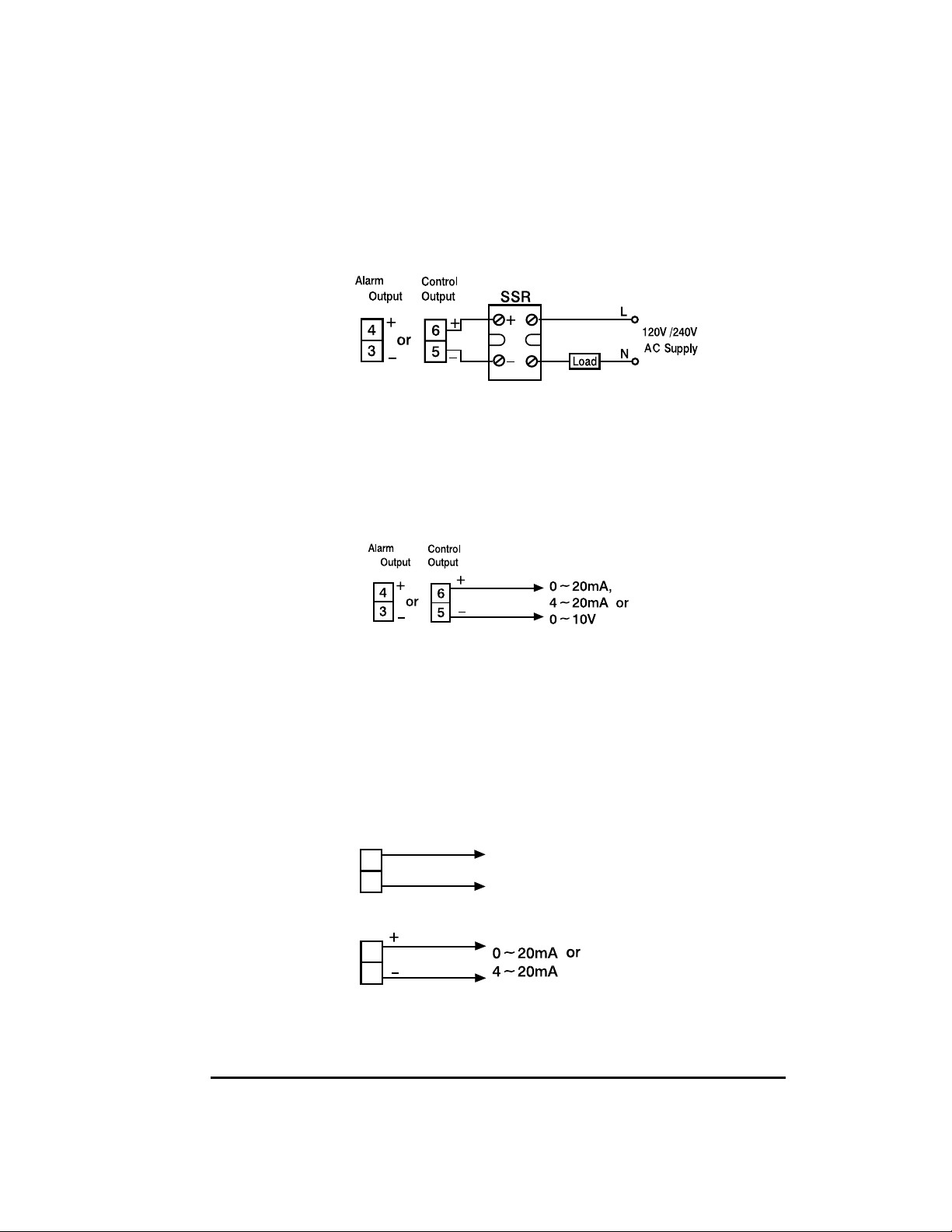
DC PULSE (SOLID-STATE RELAY DRIVE) OUTPUT
Controllers fitted with the DC pulse output produce a time-proportional non-isolated pulse voltage (0-24V nominal, output impedance 660Ω). The connections are shown in the illustration below.
DC LINEAR OUTPUT
There are three types of linear output modules that can be selected for the output. The connections are shown in the illustration
below.
RS-485 COMMUNICATIONS/ANALOG RETRANSMISSION
RS-485 serial communications or Analog retransmission of
process variable, setpoint, or manipulated variable can be selected as an optional feature. The connections are shown in the illustration below.
10
Pulsed DC output Connections
Linear DC output Connections
RS-485 Communications
Analog retransmission
2nd
/
1
2nd
/
1
13
14
13
14
TX1
TX2
Page 13
11
11
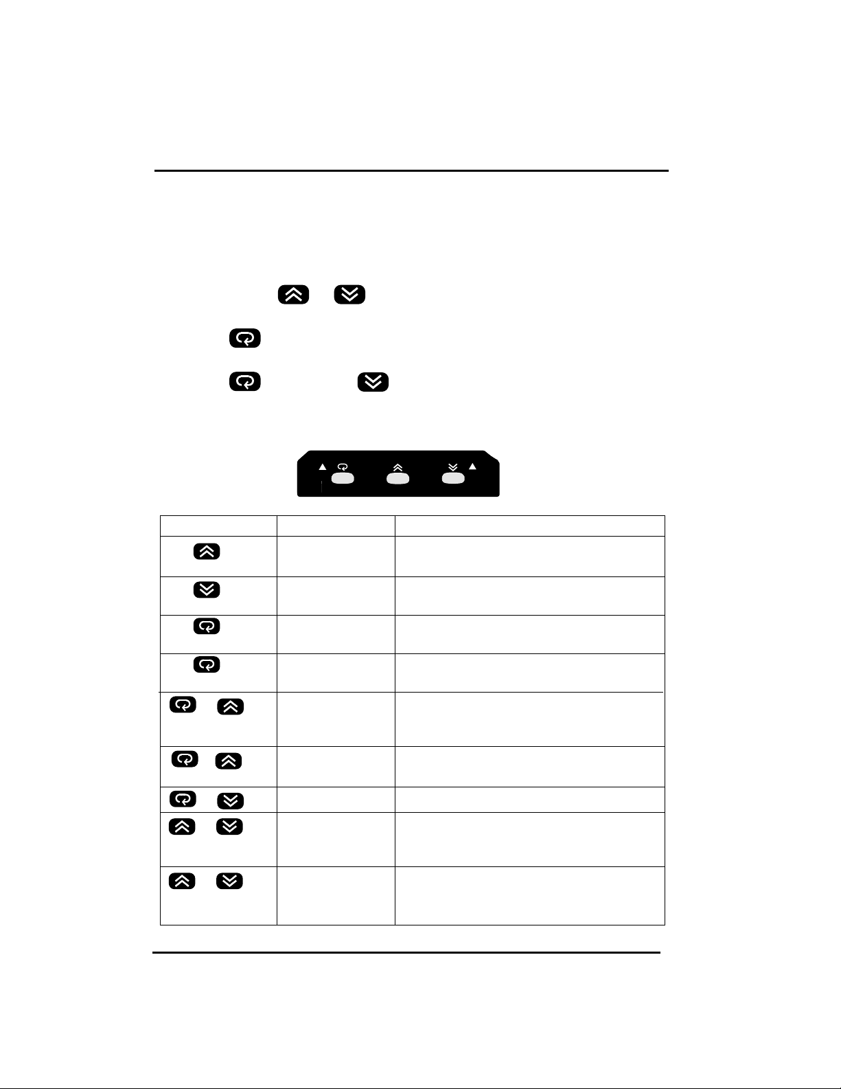
NEGOTIATING THE CN491A MENU
When the controller is powered up it automatically displays the
Process Variable (PV).
From the Process Variable (PV) display you can easily:
Press either the or key momentarily to view set-point.
or
Press the key momentarily to enter the Primary Program Menu.
or
Press the key and the key simultaneously to enter the
Tool Program Menu.
CN491
TOUCH KEYS FUNCTION DESCRIPTION
Up key Press to select digit to change. Press and hold
to increase value for parameter
Down key Press to select digit to change. Press and hold
to decrease value for parameter
Scroll key Press to select parameter in direct sequence
or to select tool program parameters
Long scroll/ Use to select protected parameters in higher
press for 3.2 seconds Enter key security level or to actuate selected tool program
&
&
press for 3.2 seconds parameters
&
&
&
press for 3.2 seconds start autotune.
Reverse scroll/ Use to select parameter in reverse sequence or
Calibration to verify display accuracy for input types during
Verification calibration
Lock key Use to disable keypad operation to protect
Tool program key Press to select tool program in sequence
Reset/Exit key Press to unlock keypad operation, to reset
display, to exit tool program, or to end autotune
and manual control execution.
Autotune key Hold both keys for 3.2 seconds then release to
Page 14

1212
LEARNING THE PARAMETERS
SV - Setpoint
This parameter is the target value for the process. It can be
adjusted throughout the range defined by the Low Scale Value
and High Scale Value
.
Set in degrees/engineering
units.
ASP1 - Alarm 1 Setpoint or Dwell Time
If output #2 is configured as an alarm this parameter sets the point
that the alarm will be activated. If output #2 is configured as a
Dwell Timer this parameter sets the amount of time to be counted.
Set in degrees/engineering units for alarms or minutes for timer.
Ramp - Ramp Rate
This determines the rate at which your process will approach setpoint. Setting this parameter to 0 will cause your system to
approach setpoint at maximum speed. Set in degrees/minute.
OFST - Offset Value for Manual Reset
For systems using proportional control only (Ti set to 0) this parameter will be adjusted to compensate for any deviation between
setpoint and process. Set 0-100% of Pb.
SHIF - Shift Process Value
This value will be added to the process value to correct for errors
or to synchronize a number of different units. Set in degrees/engineering units.
PB - Proportional Band
The proportional band is that area around main setpoint
where the control output is neither full on nor full off.
HYST - Hysteresis for ON/OFF Control
The hysteresis for output #1 is the area around the main setpoint
where the output does not change condition. It is intended to
eliminate relay chatter at setpoint for ON/OFF control applications.
Page 15

1313
Code for “Addr” Retransmission
192 4~20mA, PV
193 4~20mA, SV
194 4~20mA, MV1 (Output 1)
195 4~20mA, MV2 (Output 2)
196 0~20mA, PV
197 0~20mA, SV
198 0~20mA, MV1 (Output 1)
199 0~20mA, MV2 (Output 2)
TI - Integral Time
The integral time is the speed at which a corrective increase or
decrease in output is made to compensate for offset which usually
accompanies proportional only processes. The more the integral time
entered, the slower the action. The less the integral time entered, the
faster the action. Enter a value that would eliminate offset without
overcompensation, resulting in process oscillation.
TD - Derivative Time
The derivative time is that time used in calculating rate of change
and thermal lag in helping eliminate overshoot which results in
response to process upsets. This overshoot usually accompanies
proportional only and proportional integral processes. The derivative action dampens proportional and integral action as it anticipates where the process should be. The more the derivative time
entered, the more the damping action. The less the derivative time
entered, the less damping action. Enter as much derivative time as
necessary to eliminate overshoot without overdamping the process
resulting in process oscillation.
ADDR -
Address of unit for serial communications/ Retransmission
This unit can be assigned a numerical address to identify it as one
of 191 stations on an RS-485 serial communications loop (set from
1-191) or for 4-20mA/0-20mA retransmission (set from 192-199).
Page 16

1414
LOSC/HISC - Low/High Scale Range
If a thermocouple or RTD is being used these parameters will
establish the allowable range for the setpoint. If an analog input is
being used these parameters will establish the scaling range for
the process signal and the allowable range for the setpoint. Set in
temperature/engineering units.
PL1/PL2 - Power Limit for Heating and Cooling Outputs
These parameters limit the maximum percentage of power for the
control outputs. These are used on systems that cannot tolerate
100% power. Set from 0-100%.
INPT - Input Type Selection
Used to indicate what type of sensor input will be connected.
See
Range and Accuracy of Inputs on page 5 for available input types.
UNIT - Process Unit
Used to select the correct engineering units for the process.
(PU for Analog inputs, C or F for temperature applications).
RESO - Decimal Point Resolution
This parameter defines the position of the decimal point for the
process value and setpoint value. Set to 0,1 or 2 positions right
of the decimal point. (2 positions is reserved for linear inputs
only.)
CONA - Control Action of Output #1
Determines whether the output will be reverse acting, as in a
heating application, or direct, as in a cooling application. See
programmable control action on page 33.
A1MD - Alarm Mode Selection for Alarm #1
Refer to page 22 for the various alarm types available.
Page 17

1515
A1SF - Alarm #1 Special Function
Selects a hold function or latch function for alarm #1. Also, used to
reconfigure alarm #1 as a dwell timer. Refer to page 22 for more infor-
mation. Set to
for cooling action on output #2.
CYC/CCYC - Proportional Cycle Time for Outputs #1 & #2
These parameters determine the duration of the duty cycle for time
proportioned outputs. Set from 0-99 seconds. Set to 0 for linear outputs.
CPB/DB - Cooling Proportional Band/Dead Band
Used only when output #2 is configured for cooling applications.
Refer to page 34 for a more detailed explanation.
Page 18

1616
PRIMARY PROGRAM MENU
Press the key momentarily to enter the Primary Program
Menu.
Press the key momentarily to scroll through the Primary Program Menu.
Pause momentarily on a parameter to be changed. After 3.2 sec
the display will begin to toggle between the parameter and its current value.
Press either the or key momentarily to highlight the
numerical position to be changed.
Press and hold either the or key to increment or
decrement the desired position.
Press the key momentarily to continue scrolling through the
Primary Program Menu.
When you’ve reached the last parameter in a given level, press
and hold the key until that parameter stops flashing. This will
advance you to the next level of the Primary Program Menu.
Page 19

1717
CHANGING SETPOINT (SV)
Press either the or key momentarily to view set-point
Press either the or key momentarily to highlight the
numerical position to be changed.
Press and hold either the or key to increment or decrement the desired position.
After approximately 10 seconds the unit will automatically return
to reading the Process Variable (PV).
BEGIN CONTROLLING
1. Insure that the controller is properly wired for your application.
As soon as the unit is powered up it will begin trying to
control at the current setpoint.
2. Check the display of the controller. Make sure that it is
reading the actual temperature/engineering units.
3. If everything looks correct set the desired setpoint, go to the
auto-tune procedure (page 20) and initiate it. When autotune is
complete your system will be ready.
4. If you experience problems go to the troubleshooting section
(p.38).
Page 20

1818
FLOW CHART OF PARAMETERS
The following chart shows a typical (default) access sequence of parameters.
Normal Display Process value / setpoint value
Alarm 1 Set Point Value or Dwell
Time ( = or )
or
or
or
or
or
or
or
or
or
or
or
or
Long
Long
Ramp Rate
Offset Value for Manual Reset
(Integral Time TI=0 )
Shift Process Value
Proportional Band of Output 1
Integral (Reset) Time of Output 1
Derivative (Reset) Time of Output 1
Hysteresis of Alarm 1
Hysteresis of ON-OFF control
Address of the unit for the
communication
Low Scale of Range Adjust
for your process
High Scale of Range Adjust for
your process
Power Limit of Output 1
Power Limit of Output 2
Input Type Selection
Low scale~high scale value (for Full Scale Alarm), -111.0 ~ 111.0°C or -199.9 ~199.9°F
(for Deviation and Deviation Band Alarm), 0~9999 minutes (for Dwell Time) **18.0°F
0-55.55°C/minute or 0 ~ 99.99°F/minute **0.00
0~100.0% **0.0
0~200.0°C or 0~360.0 °F, 0-3600 P.U.
0:For ON-OFF control
**18.0°F
-111.0~111.0 °C or -199.9~199.9°F **0.0°F
0~3600 seconds**120
0~1000 seconds**40
0~11.0°C or 0.1~ 19.9°F **00.1°F
0~11.0°C or 0.1~ 19.9°F **00.1°F
0~40 **00
Minimum value for the selected input (INPUT) to
High Scale (HISC) **000.0°F
Low Scale (LOSC) to maximum value for the
selected input (INPUT) **999.9°F
0~100%
**100
0~100%
**100
:J TYPE T/C
:K TYPE T/C
:T TYPE T/C
:E TYPE T/C
:B TYPE T/C
:R TYPE T/C
:S TYPE T/C
:N TYPE T/C
:PT100 DIN
:PT100 JIS
:4~20MA
:0~20MA
:0~1V
:0~5V
:1~5V
:0~10V
:degree C
:degree F
:process unit
Voltage or
Current Input)
Level 0
Level 1
or
or
or
Low scale to high scale value **212.0°F
:Deviation High
Alarm.
:Deviation Low
Alarm.
**
or
**
**
Page 21

1919
Low Alarm.
High Alarm.
:Deviation Band
:Deviation Band
Alarm.
Alarm.
Full Scale Low
:Full Scale High
:No Decimal
Point Used
**
or
or
:1 Digit Decimal
:2 Digit Decimal
:Direct
(Cooling)
Action.
:Reverse
or
(only for Linear
Voltage or
Current Input)
(Heating)
Action.
**
or
or
:No Special Function
**
:Alarm with Hold Function
:Alarm with Latch Function
0~99 Seconds, 0 for
Linear current/Vol-
tage output. **20
0~99 Seconds, 0 for
Linear current/Vol-
or
or
:Alarm with Latch & Hold Function
:Dwell Timer ON as Time Out.
:Dwell Timer OFF as Time Out.
:Proportional cooling
tage output. **20
0.0~200.0°C or 0.1~
360.0°F **18.0°F
-111.0~111.0°C or
-199.9~199.9°F,
**000.0°F
or
or
Resolution Selection
Select Unit
Alarm 1 Mode
Control Action of Output 1
Level 2
Alarm 1 Special Function
Proportional Cycle Time of Output 1
Cooling P Band
Cooling Cycle Time
Dead Band for PB and CPB
Note: Using the Tool Program the display sequence and the security level for any parameter are configurable. Also, any unused
parameter can be removed from the display sequence to simplify the operation.
**: Denotes the default setting
Long : Press and hold for at least 3.2 seconds
Page 22

2020
AUTO-TUNING
Auto-tune is a procedure that will oscillate your process around
setpoint twice, testing the dynamics of your system and automatically setting the P, I, and D parameters.
You should auto-tune your system:
- during initial set-up.
- if setpoint is changed by a large amount.
- if sensor or output is changed.
TO COMPLETE THE AUTO-TUNE PROCEDURE;
1. Make sure all parameters are configured correctly.
2. Have system under normal load conditions.
3. Make sure Pb(Proportional band) is not 0.
4. Set the setpoint to the normal operating temperature.
Note: If system overshoot is likely to cause damage, reduce the
setpoint during autotune.
5. Press and hold the and keys for 3.2 seconds and then
release. The display will begin flashing and will continue to
flash throughout the auto-tune process.
Note: To abort the autotune process, press and release the
and keys during the first oscillation of the process.
Page 23

21
ALARMS
This controller is available with a second output that can be configured for a variety of alarm types. The following parameters in
the Primary Program Menu are used to configure the alarms;
Alarm 1 setpoint - This parameter determines the point
that alarm 1 will be activated.
Example: Deviation high alarm with no special function
SV= 100°C, ASP1= 10°C, AHY1= 4°C
Alarm 1 Hysteresis - This parameter establishes an area
around Alarm 1 setpoint where the alarm relay will not
change states.
21
Alarm ON
Low Alarm
Setpoint
Alarm OFF Alarm OFF
Low Alarm
Hysteresis
Main
Setpoint
High Alarm
Hysteresis
Alarm ON
High Alarm
Setpoint
Page 24

22
Alarm 1 mode - This parameter determines the alarm
type that is to be used, such as a deviation alarm, a
band alarm, or an absolute alarm.
Alarm 1 Spec. Func.- This parameter assigns special
functions to Alarm 1 such as a holding feature
that prevents an alarm during start up or a latch func-
tion that prevents the alarm from clearing
unless power is interrupted.
Example: Deviation low alarm with Hold function.
22
Code
1 Full scale high
Type
Alarm Set point
PV
2 Full scale low
Alarm Set point
Alarm Set point
3 Deviation high
Set point
Alarm Set point
4 Deviation low
Set point
Alarm Set point
7 Deviation band high
Set point
8 Deviation band low
Set point
PV
PV
PV
PV
PV
Page 25

2323
SETTING ALARMS
To set an alarm:
Press the key momentarily to enter the Primary Program
Menu.
Press the key momentarily to scroll through the Primary Program Menu until you come to .
Pause momentarily. After 3.2 sec the display will begin to toggle
between and its current setting.
Press and hold either the or key to select the desired
alarm type.
Press the key momentarily to continue scrolling through the
Primary Program Menu until you come to .
Pause momentarily. After 3.2 sec the display will begin to toggle
between and its current setting.
Press and hold either the or key to select the desired
alarm special function.
Press the key momentarily to continue scrolling through the
Primary Program Menu until you come to .
Pause momentarily. After 3.2 sec the display will begin to toggle
between and its current setting.
Page 26

2424
Press either the or key momentarily to highlight the
numerical position to be changed.
Press and hold either the or key to select the desired
alarm set point.
Press the key momentarily to continue scrolling through the
Primary Program Menu until you come to .
Pause momentarily. After 3.2 sec the display will begin to toggle
between and its current setting.
Press either the or key momentarily to highlight the
numerical position to be changed.
Press and hold either the or key to select the desired
amount of alarm hysteresis.
SCALING ANALOG INPUTS/SETTING SETPOINT LIMITS
When an analog input such
as 4-20 mA signal is applied
to this unit it is necessary to
tell the unit how this signal
is to be scaled.
SCALING 1-5V dc AND 4-20mA dcINPUT RANGES
Example: Program a 4-20mA dc signal for 0 to 100 P.U.
Input Type
4-20mA dc
Program to 0
to 100
Full Range = (100-0) = 100 Engineering Units
-5 0 100 105
5% 5%
Minimum/Maximum Range
-1400...9400 Enginerring Units
Setpoint Range
Indicating Range
Page 27

2525
When a thermocouple or RTD
is applied to this controller it
may be necessary to establish
limits that the setpoint can be
set within in order to protect
the system from over/ undertemperature situations.
Parameters (zero
point/lower setpoint limit) and (span point/upper setpoint
limit) are used to scale analog inputs or to establish setpoint
limits.
TO SET THESE PARAMETERS;
Press the key momentarily to enter the Primary Program
Menu.
Press the key momentarily to scroll through the Primary Program Menu until you come to / .
Pause momentarily. After 3.2 sec the display will begin to toggle
between / and its current setting.
Press either the or key momentarily to highlight the
numerical position to be changed.
Press and hold either the or key to enter the desired
value.
SCALING THERMOCOUPLE AND RTD(Pt100) INPUT RANGES
Example: Program a J thermocouple for 50 to 500 F
Minimum/Maximum Range
32 . . . . . . . . . . . . .1832 F
Setpoint Range
Input Type
J Thermocouple
Program to 50
to 500
Full Range = (500-50) = 450 F
27.5 50 500 522.5
5% 5%
Indicating Range
Page 28

2626
RAMP FUNCTION
If the ramp function is enabled the process will increase or
decrease, during initial power up and setpoint changes, at a rate
determined by the parameter which can be adjusted in
units/minute. This function will be disabled when is set
to zero.
TO SET A RAMP RATE;
Press the key momentarily to enter the Primary Program
Menu.
Press the key momentarily to scroll through the Primary Program Menu until you come to .
Pause momentarily. After 3.2 sec the display will begin to toggle
between and its current value.
Press either the or key momentarily to highlight the
numerical position to be changed.
Press and hold either the or key to increment or decrement the desired position.
Press the key momentarily to continue scrolling through the
Primary Program Menu.
Change of Setpoint
Page 29

2727
RAMP & SOAK/DWELL FUNCTION
A dwell timer has been incorporated into this controller.
Alarm #1 can be configured by setting = or
to provide either a dwell function or a soak function to be
used in conjunction with the ramp function.
The ramp and soak function will allow the system to be pro-
grammed to approach setpoint at a specific ramp rate, hold the
setpoint temperature for a set amount of time and then shut off the
alarm relay. When the output is wired in series with the alarm
relay, the output will turn off when the alarm relay shuts off. This
will end the soak cycle and return the process to ambient conditions until the controller is reset.
TO SET A SOAK/DWELL TIME
Follow the procedure outlined in Ramp Function to set a ramp rate.
While in the Primary Program Menu continue to scroll until you
come to parameter .
Pause momentarily. After 3.2 sec the display will begin to toggle
between and its current value.
continued on page 28
Page 30

2828
Press and hold either the or key to increment or decrement to the desired position, to turn the relay on after the
amount of time defined by or to turn the relay off
after the amount of time defined by .
Press the key momentarily to continue scrolling through the
Primary Program Menu until you come to parameter .
Pause momentarily. After 3.2 sec the display will begin to toggle
between and its current value.
Press either the or key momentarily to highlight the
numerical position to be changed.
Press and hold either the or key to increment or
decrement the desired time setting.
Page 31

2929
TOOL PROGRAM MENU
Press the key and the key simultaneously to enter the
Tool Program Menu.
Press the key and the key simultaneously to scroll
through the main headings of the Tool Program Menu.
Press the key to access the parameters under each main
heading within the Tool Program Menu.
Pause momentarily on a parameter to be changed. After 3.2 sec
the display will begin to toggle between the parameter and its current value.
Press either the or key momentarily to highlight the
numerical position to be changed.
Press and hold either the or key to increment or decrement the desired position.
Press the key momentarily to continue scrolling through the
parameters within that heading,
or
Press the key and the key simultaneously to continue
scrolling through the main headings of the Tool Program Menu.
Page 32

Enter the manual control mode.
Allow to adjust the percentage value of
Heating output by using or . 000~100%
Flow Chart of Tool Programs
View the percentage power
of Heating output.
or
or
or
or
View the percentage power
of Cooling output (Alarm).
View the maximum (peak) process value.
View the minimum (peak) process value.
Adjust the cold-junction
compensation code.
(-19.9~42.7 count)
Adjust the drift
compensation code.
(-6.6~6.6 count)
Select a proper status for Output .
:Output ON ** : : Output OFF
Select a proper status for Alarm .
** :Alarm ON : Alarm OFF
Enter the manual control mode.
Allow to adjust the percentage value of
Cooling output (Alarm) by using or . 000~100%
Reset the maximum and
minimum process values.
Reset the maximum and
minimum process values.
Calibrate the A-D and enter the
cold-junction compensation
Calibrate the 0~20mA and enter it.
Enter the drift compensation code.
Enter the status.
Enter the status.
Hand (manual)
control.
Read peak
process value.
Calibrate
A-D converter*.
Define protection
mode for the
status of control
and alarm
outputs 1 & 2 to
ensure a safe
condition while
the control fails.
Long
Long
Long
Long
Long
Long
Long
Long
Long
Page 33

3131
or
or
or
or
or
or
Select Lock or Free for the Security Level 0.
: Protect (Lock) all the Level 0 parameters.
** : Allow all the Level 0 parameters to be adjustable.
Select Lock or Free for the Security Level 1.
: Protect (Lock) all the Level 1 parameters.
** : Allow all the Level 1 parameters to be adjustable.
Select Lock or Free for the Security Level 2.
: Protect (Lock) all the Level 2 parameters.
** : Allow all the Level 2 parameters to be adjustable.
Change the value of
security level for the
selected parameter.
Change the value of
security level for the
selected parameter.
Display the rest of
parameters according
to the standard access
sequence.
Change the value of
security level for the
selected parameter.
Enter the updated
security level of ASP1.
Enter the updated
security level of RAMP.
Enter the selection
Enter the selection
Enter the selection
Enter the updated
security level of DB.
Lock
parameters.
Configure
security
levels for all
parameters.
:Security LEVEL
= 0 :Put the parameter
in LEVEL 0.
= 1 :Put the parameter
in LEVEL 1.
= 2 :Put the parameter
in LEVEL 2.
=3 :Mask parameter
Long
Long
Long
Long
Long
Long
* Do not proceed through this section unless there is a definite need to re-calibrate the controller.
All previous calibration data will be lost.
Page 34

3232
MANUAL CONTROL
The outputs of this controller can be used in a manual mode. This
enables the operator to apply a specific percentage of power to
the system.
To use this unit in manual mode:
Enter the Tool Program Menu by pressing the and the
key simultaneously.
The display will toggle between and .
Press the key momentarily.
The display will toggle between the process variable and the current output percentage .
To change output #1 skip this step, to change output #2 press the
key momentarily to display the output percentage for the
cooling output .
Press and hold the key for 3.2 seconds.
The display will begin flashing as it toggles between the process
variable and .
Use the and keys to highlight and change the display
to the desired output percentage.
Example:
is viewed with cycle
time =10 sec.
The output 1 will act as shown:
Page 35

33
PROGRAMMABLE CONTROL ACTION
Output #1 can be used in a reverse action configuration (heating
applications) or in a direct action configuration (cooling applica-
tions) by adjusting parameter .
To adjust the control action of output #1;
Press the key momentarily to enter the Primary Program
Menu.
Press the key momentarily to scroll through the Primary Program Menu until you come to .
Pause momentarily. After 3.2 sec the display will begin to toggle
between and its current setting.
Press and hold either the or key to select the desired
control action ( = direct / = reverse).
33
Reverse Action
PB
100%
Output
0%
Main Setpoint
Note: PB = Proportional Band
PV
100%
Output
Direct Action
PB
0%
Main Setpoint
PV
Page 36

3434
COOLING CONTROL
This controller has the option of being configured as a single or a
dual output controller.
The alarm output can be used as a control output by setting
parameter in the Primary Program Menu to
.
Once this is done the following parameters are used as output #2
control parameters;
CPB: Cooling Proportional Band
DB: Dead Band
CCYC: Cooling Cycle Time
Page 37

3535
CONFIGURABLE MENUS
This controller gives you the flexibility to configure the menus in a
way that is most convenient for your application. There are four
menu levels that parameters in the primary program menu can be
assigned to.
-
This is the first group of parameters within the Primary
Program Menu. Locate parameters here that need to
be changed frequently or that need to be accessed
easily.
-
This is the second group of parameters within the Primary Program Menu. Locate parameters here that
need to be accessed but not frequently.
-
This is the third group of parameters within the Primary Program Menu. Locate parameters here that are
specific to your application but are not going to be
changed.
-
This is a level used to mask parameters that are not
used for your application or parameters that are not to
be accessed by the operator.
continued on page 36
Page 38

3636
TO ASSIGN PARAMETERS TO A SPECIFIC LEVEL
Press the key and the key simultaneously to enter the
Tool Program Menu.
Press the key and the key simultaneously to scroll
through the Tool Program Menu until you come to .
Pause momentarily. After 3.2 sec the display will begin to toggle
between and .
Press the key to access the parameters under this, contained
within the primary program menu and their current menu level.
Pause momentarily on a parameter to be changed. After 3.2 sec
the display will begin to toggle between the parameter and the
level it is currently assigned to.
Press and hold either the or key to increment or decrement to the menu level desired.
Press and hold the key for 3.2 sec to register the selection.
Page 39

3737
LOCKING MENUS
The various menu levels within the Primary Program menu can be
left free so that information can be viewed as well as changed, or
any of the levels can be locked so that the information can only be
viewed but not changed.
TO LOCK A MENU LEVEL WITHIN THE PRIMARY PROGRAM MENU
Press the key and the key simultaneously to enter the
Tool Program Menu.
Press the key and the key simultaneously to scroll
through the Tool Program Menu until you come to .
Pause momentarily. After 3.2 sec the display will begin to toggle
between and .
Press the key to access the parameters -
.
Pause momentarily on a menu level to be changed. After 3.2 sec
the display will begin to toggle between the parameter and the
lock setting it is currently set to.
Press and hold either the or key to increment or decrement to the lock level desired ( = locked, =
accessible).
Press and hold the key for 3.2 sec to register the selection.
Page 40

38
ERROR MESSAGES
Symptom Probable Cause(s) Solution
Process display shows: - Sensor break - Replace RTD or sensor
- Use manual mode
operation
Process display shows: - Input signal beyond the - Replace sensor
low range, sensor fails - Check sensor or thermocouple
type, correct input selection
Process display shows: - Input signal beyond the - Replace sensor
high range, sensor fails - Check sensor or thermocouple
type, correct input selection
Process display shows: - A to D module damage - Replace module
- Check for outside source of
damage such as transient
voltage spikes
Process display shows: - Incorrect operation of - Repeat procedure.
auto tune procedure Increase Prop. band to a
- Manual mode is not number larger than 0.
allowed for an ON-OFF
control system
Process display shows: - Check-sum error, values - Check and reconfigure
in memory may have control parameters
changed accidentally.
Process display shows: - Fail to enter data into - Replace EEPROM
EEPROM
Process display shows: - Overflow error, data out - Check if there is noise
of range during coming in.
execution of program - Replace EEPROM.
Process Display shows: - Attempt to change a - UNLOCK procedure stated in
locked parameter the flow chart of tool programs.
38
Page 41

39
NOTES
39
Page 42

FOR W
ARRANTY
RETURNS, please have the following
information available BEFORE contacting OMEGA:
1. Purchase Order number under which the product was
PURCHASED,
2. Model and serial number of the product under
warranty, and
3. Repair instructions and/or specific problems relative
to the product.
FOR NON-W
ARRANTY
REPAIRS,
consult OMEGA
for current repair charges. Have the following
information available BEFORE contacting OMEGA:
1. Purchse Order number to cover the
COST of the repair,
2. Model and serial number of the product, and
3. Repair instructions and/or specific problems
relative to the product.
OMEGA’ s policy is to make running changes, not model changes, whenever an improvement is possible. This
affords our customers the latest in technology and engineering.
OMEGA is a registered trademark of OMEGA ENGINEERING, INC.
© Copyright 1998 OMEGA ENGINEERING, INC. All rights reserved. This document may not be copied, photocopied,
reproduced, translated, or reduced to any electronic medium or machine-readable form, in whole or in part, without
the prior written consent of OMEGA ENGINEERING, INC.
WARRANTY/DISCLAIMER
OMEGA ENGINEERING, INC. warrants this unit to be free of defects in materials and workmanship for a period of 37 months from date of purchase. OMEGA Warranty adds an additional one (1) month grace period
to the normal three (3) year product warranty to cover handling and shipping time. This ensures that
OMEGA’s customers receive maximum coverage on each product.
If the unit malfunctions, it must be returned to the factory for evaluation. OMEGA’s Customer Service Department
will issue an Authorized Return (AR) number immediately upon phone or written request. Upon examination by
OMEGA, if the unit is found to be defective, it will be repaired or replaced at no charge. OMEGA’s WARRANTY does
not apply to defects resulting from any action of the purchaser, including but not limited to mishandling, improper
interfacing, operation outside of design limits, improper repair, or unauthorized modification. This WARRANTY is
VOID if the unit shows evidence of having been tampered with or shows evidence of having been damaged as a
result of excessive corrosion; or current, heat, moisture or vibration; improper specification; misapplication; misuse
or other operating conditions outside of OMEGA’s control. Components which wear are not warranted, including but
not limited to contact points, fuses, and triacs.
OMEGA is pleased to offer suggestions on the use of its various products. However, OMEGA
neither assumes responsibility for any omissions or errors nor assumes liability for any
damages that result from the use of its products in accordance with information provided by
OMEGA, either verbal or written. OMEGA warrants only that the parts manufactured by it will
be as specified and free of defects. OMEGA MAKES NO OTHER WARRANTIES OR
REPRESENTATIONS OF ANY KIND WHATSOEVER, EXPRESS OR IMPLIED, EXCEPT THAT OF
TITLE, AND ALL IMPLIED WARRANTIES INCLUDING ANY WARRANTY OF MERCHANTABILITY
AND FITNESS FOR A PARTICULAR PURPOSE ARE HEREBY DISCLAIMED. LIMITATION OF
LIABILITY: The remedies of purchaser set forth herein are exclusive, and the total liability of
OMEGA with respect to this order, whether based on contract, warranty, negligence,
indemnification, strict liability or otherwise, shall not exceed the purchase price of the
component upon which liability is based. In no event shall OMEGA be liable for consequential,
incidental or special damages.
CONDITIONS: Equipment sold by OMEGA is not intended to be used, nor shall it be used: (1) as a “Basic
Component” under 10 CFR 21 (NRC), used in or with any nuclear installation or activity; or (2) in medical
applications or used on humans. Should any Product(s) be used in or with any nuclear installation or
activity, medical application, used on humans, or misused in any way, OMEGA assumes no responsibility as
set forth in our basic WARRANTY/ DISCLAIMER language, and, additionally, purchaser will indemnify
OMEGA and hold OMEGA harmless from any liability or damage whatsoever arising out of the use of the
Product(s) in such a manner.
RETURN REQUESTS/ INQUIRIES
Direct all warranty and repair requests/inquiries to the OMEGA Customer Service Department. BEFORE
RETURNING ANY PRODUCT(S) TO OMEGA, PURCHASER MUST OBTAIN AN AUTHORIZED RETURN (AR)
NUMBER FROM OMEGA’S CUSTOMER SERVICE DEPARTMENT (IN ORDER TO AVOID PROCESSING
DELAYS). The assigned AR number should then be marked on the outside of the return package and on any
correspondence.
The purchaser is responsible for shipping charges, freight, insurance and proper packaging to prevent
breakage in transit.
Page 43

TEMPERATURE
Thermocouple, RTD & Thermistor
Probes, Connectors, Panels & Assemblies
Wire: Thermocouple, RTD & Thermistor
Calibrators & Ice Point References
Recorders, Controllers & Process Monitors
Infrared Pyrometers
PRESSURE, STRAIN
AND FORCE
Transducers & Strain Gauges
Load Cells & Pressure Gauges
Displacement Transducers
Instrumentation & Accessories
FLOW/LEVEL
Rotameters, Gas Mass Flowmeters
& Flow Computers
Air Velocity Indicators
Turbine/Paddlewheel Systems
Totalizers & Batch Controllers
pH/CONDUCTIVITY
pH Electrodes, Testers & Accessories
Benchtop/Laboratory Meters
Controllers, Calibrators, Simulators
& Pumps
Industrial pH & Conductivity Equipment
DATA ACQUISITION
Data Acquisition &
Engineering Software
Communications-Based
Acquisition Systems
Plug-in Cards for Apple, IBM
& Compatibles
Datalogging Systems
Recorders, Printers & Plotters
HEATERS
Heating Cable
Cartridge & Strip Heaters
Immersion & Band Heaters
Flexible Heaters
Laboratory Heaters
ENVIRONMENT AL
MONITORING AND CONTROL
Metering & Control Instrumentation
Refractometers
Pumps & Tubing
Air, Soil & Water Monitors
Industrial Water & Wastewater
Treatment
pH, Conductivity & Dissolved
Oxygen Instruments
Where Do I Find Everything I Need for
Process Measurement and Control?
OMEGA…Of Course!
M2901/0998
 Loading...