


Page 1

Page 2
1
Page 3

CONTENTS
MODEL CONFIGURATION……………………………………………….………………………...……………………………. 3
SPECIFICATIONS……………….………………………………………………………..………………………………………...7
PARAMETER AND SETTING…………………………………………………………………….………………………………11
FIELD PARAMETER TABLE …………………………………………………………….……………………………………… 13
SYSTEM PARAMETER TABLE…………………………………………………………………………………………………. 15
SYMBOL DESCRIPTIONS………………………………………………………………………………………………………33
INSTRUMENT INSTALLATION AND WIRING…………………………………………………………………..……………34
DISPLAYS AND OPERATIONS………………………………………………………….………………………………………36
OPERATION DESCRIPTION………………………………………………………………………………………………….…38
PARAMETER SETTING FLOW CHART…..…………………………………………………………………………….………46
PROGRAMMING AND OPERATION……………………………….....……………..…………………………………………47
2
Page 4

MODEL CONFIGURATION
Model
CN4316(*)-(**)-(***)
CN434(*)-(**)-(***)
CN438V(*)-(**)-(***)
CN438H(*)-(**)-(***)
Description
1/16 DIN controller, Support 0~5/1~5V Voltage Input
1/4 DIN controller, Support 0~5/1~5V Voltage Input
1/8 DIN Vertical controller, Support 0~5/1~5V Voltage Input
1/8 DIN Horizontal controller, Support 0~5/1~5V Voltage Input
3
Page 5

Programmable Controller
CN4416(*)-(**)-(***)
CN444(*)-(**)-(***)
CN448V(*)-(**)-(***)
CN448H(*)-(**)-(***)
1/16 DIN controller, 30 Segment, Support 0~5/1~5V Voltage Input
1/4 DIN controller, 30 Segment, Support 0~5/1~5V Voltage Input
1/8 DIN Vertical controller, 30 Segment, Support 0~5/1~5V Voltage Input
1/8 DIN Horizontal controller, 30 Segment, Support 0~5/1~5V Voltage Input
* Specify controlling output code from Output Options table below
** Specify alarm output code from Alarm Options table below
*** Low voltage power supply option (-LV)
4
Page 6

Control output options
Option Type Controlling output code
Relay -R1
DC SSR driver -DC1
4~20 mA Linear Current -F1
5
Page 7

Alarm output options
Option Type
Relay -R2
DC SSR driver -DC2
Alarm output code
Low voltage power supply option
-LV 24V AC/DC, 50/60 Hz
6
Page 8
SPECIFICATIONS
Input
Type
Range
℃/ ℉
Input Type
Range ℃/ ℉
Thermocouple
K S R E J T B N
-50 to1300 ℃
-58 to 2372 ℉
-50 to1700℃
-58 to 3092 ℉
-50 to1700℃
-58 to 3092 ℉
0 to 800℃
32 to 1472 ℉
0 to1000℃
32 to 1832 ℉
-200 to 350℃
-328 to 662 ℉
200 to1800℃
392 to 3272 ℉
0 to 1300℃
32 to 2372 ℉
RTD
Cu50 PT100
-50 to 150℃
-58 to 302 ℉
-200 to 800℃
-328 to 1472 ℉
7
Page 9

Input Type
Accuracy
Display Resolution
Linear Voltage
0 to 5V, 1 to 5V, 0 to 1V,
0 to 20mV, 0 to 100mV
Linear Current
(external resistor needed)
0 to 10mA, 0 to 20mA, 4 to 20mA
0.3%FS ± 0.1℃/ 0.18
℉
0.1℃/0.1℉
8
Page 10

ON / OFF Control
Control Method
Output Type
Alarm
AI PID Control with Auto Tuning (AT)
Standard PID with Auto Tuning (AT)
Relay Output (1A/250VAC)
Voltage Output for SSR (15V/30mA)
Linear Current (4 to 20 mA)
Limit High / Limit Low
High deviation / Low deviation
9
Page 11

Supply Voltage
100~240VAC (-15%, +10%), or 24VDC
50~60Hz
Power Consumption
Operating Environments
Electromagnetic compatibility
≦ 3W
Temperature: -10~+60℃ / 14~140℉
Humidity: 0~90RH%
IEC61000-4-4: ± 4KV/5KHz, IEC61000-4-5: 4KV
10
Page 12
PARAMETER AND SETTING
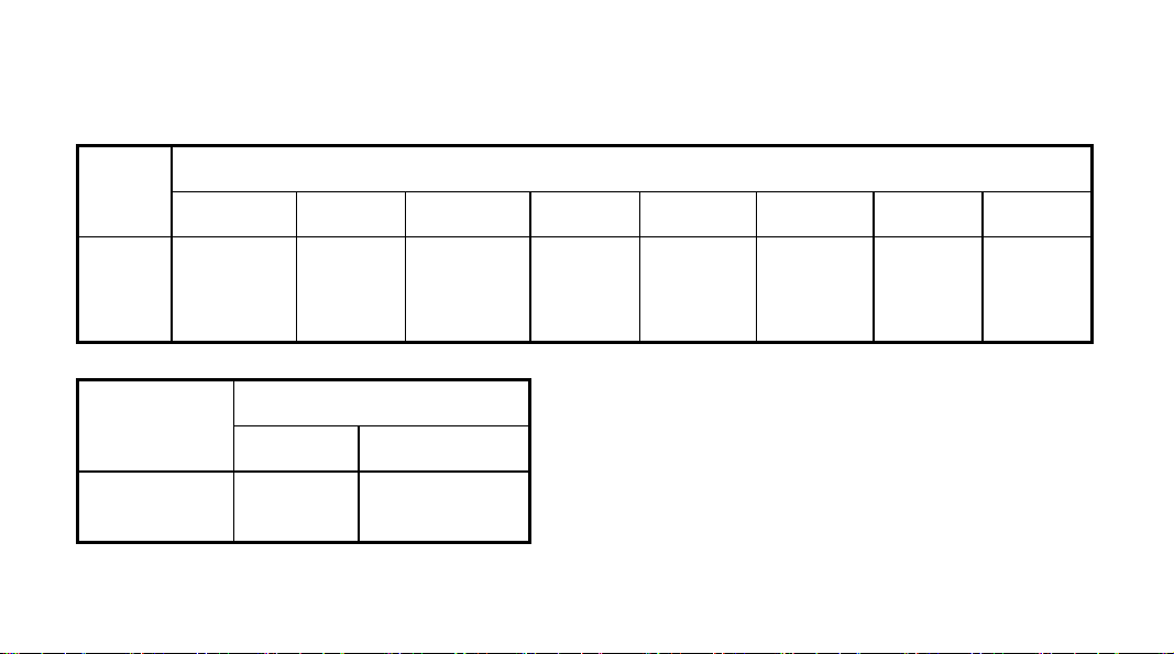
Parameter is protected by LOC (Parameter LOCK) to prevent setting error. The function was shown as
below:
√ : allow to modify data or execute
X : not allow to modify data or execute
Run, Stop, Hold. and Program Time & Temp. function just for CN 44 only
Loc SV AT
0 √ √ √ X √ √
1 √ X √ X X √
2 X X √ X √ X
3 X X √ X X X
Primary
Parameter
Secondary
Parameter
Status changing to
Run, Stop or Hold
11
Program Step Time & Temp.
Page 13
4~255 X X X X X X
808 √ √ √ √ √ √
Loc 808 is the master password, can be changed by parameter PASd.
Please set PASd cautiously, if the password lost, you can’t access the parameter table again.
1 to 8 field parameters can be defined by parameters EP1 to EP8. If the number of the field parameters
is less than 8, the first idle EP parameter should be set to “nonE”. The initial values of EPs and Loc are
EP1=HIAL, EP2=LoAL, EP3=HdAL, EP4=LdAL, EP5=nonE, EP6=nonE, EP7=nonE, EP8=nonE and
Loc=0.
You can redefine field parameters and Loc to change operation style. For example, you can execute
auto tuning from field parameter instead of by pressing
in basic display status, and only take HIAL
and HdAL as field parameter.
The EP paramters and Loc should be set as below:
EP1=HIAL, EP2=HdAL, EP3=At, EP4=nonE, Loc=1
12 13
Page 14

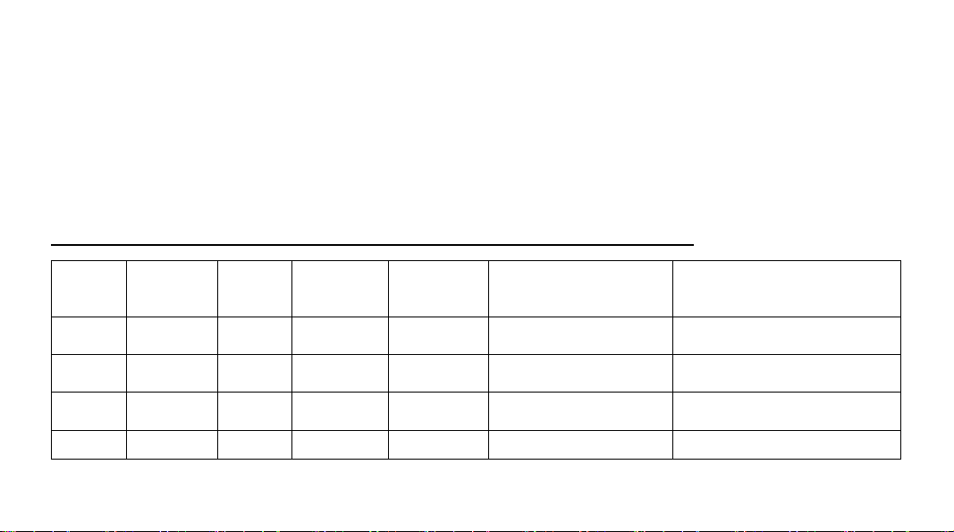
Field parameter table (Primary parameters)
Code Description Remarks
Alarm on when PV>HIAL
HIAL
High limit alarm
LoAL Low limit alarm
HdAL Deviation high alarm
Alarm off when PV<HIAL-AHYS,
When the value set to Max. will disable this function
Alarm on when PV<LoAL;
Alarm off when PV>LoAL+AHYS,
When the value set to Min. will disable this function
Alarm on when PV-SV>HdAL;
Alarm off when PV-SV<HdAL-AHYS,
When the value set to Max. will disable this function
Setting
Range
-9990~30000
Page 15

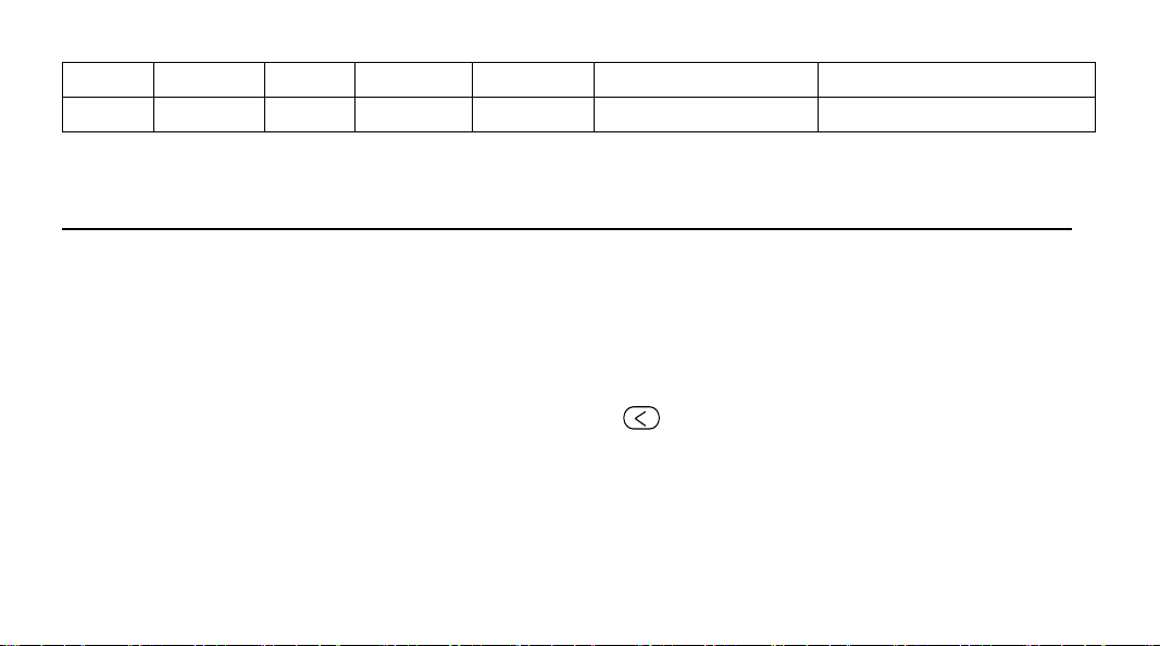
LdAL Deviation low alarm
Alarm on when PV-SV<LdAL;
Alarm off when PV-SV>LdAL+AHYS,
When the value set to Min. will disable this function
14
Page 16

System parameter table (Secondary parameters)
Set the parameter ‘Loc’=808 to enter:
***: Those Parameters just for CN 44 (Programmable Controller) Only
AHYS Alarm hysteresis
AdIS
Alarm display
Avoid frequent alarm on-off action because of the
fluctuation of PV
oFF : Will not display alarm message in the lower
display window when alarming;
on : Alternately display alarm message in the lower
display window when alarming.
15
0~2000
oFF / on
Page 17
Output to
Alarm
LdAL
(x 1000)
HdAL
(x100)
LoAL
(x10)
HIAL
(x1)
AOP
Alarm output
assignment
None
AL1
AU1
0 0 0 0
1 1 1 1
3 3 3 3
eg: AOP=1101 means LdAL, HdAL and HIAL have
alarm action from AL1; LoAL, no alarm action.
For 1/4 DIN and 1/8 DIN controller, the alarm contact
will trigger form AL1. (Terminal No.5 and No.7)
For 1/16 DIN controller, the alarm contact will trigger
form AU1. (Terminal No.3 and No.5, need set
parameter bAud=0)
16
0~4444
Page 18

CtrL
Srun
Control mode
Running status
onoF : On-off control
APId : AI PID control, high precision (Recommend)
nPId: Standard PID algorithm with
Anti-integral-saturation function (no integral when
PV-SV > proportional band);
PoP: Transmit PV. The instrument works as a
temperature retransmitter.
SoP: No function
run: Control was running, “RUN” led light on
StoP: Control was stopped. Lower display keep
flashing “StoP” and “RUN” led light off.
HoLd: Keeping Temperature. If the parameter
Pno=0(Non timing limitation mode), controller keep
running and cannot change the running status from
17
OnoF /
APId, nPID
/ PoP,
SoP
run / StoP /
HoLd
Page 19

Act
Acting method
panel, if Pno>0 (in program mode), and Srun was shown
HoLd, means
the timer stops and the temperature
remains; user can resume the time by pressing the
“Hold” from panel.
rE: Reverse acting. Increase in measured variable
causes decrease in the output, such as heating control.
dr: Direct acting. Increase in measured variable causes
an increase in the output, Such as refrigerating control.
rEbA: Reverse acting with low limit alarm and deviation
low alarm blocking when the beginning of power on.
drbA: Direct acting with high limit alarm and deviation
high alarm blocking when the beginning of power on.
rE /dr/
rEbA/drbA
At
Auto tuning
oFF: Auto tuning function was off.
on: Active auto turning function to calculate the values
18
oFF / On /
FoFF
Page 20

FoFF : Auto tuning function was off, cannot activate
again by pressing key from panel .
P Proportion band Proportion band in PID with unit ℃ or ℉ 1~32000
I Time of Integral No integral effect when I=0, with unit 1 Sec.
d
Time of
derivative
No derivative effect when d=0, with unit 0.1 Sec.
1~9999
Sec
0~3200
Sec
Small value can improve control accuracy. For SSR
output, generally 0.5 to 3 seconds.
Large value can increase using life of relay. For Relay
CtI Control period
output, generally 15 to 40 seconds.
When parameter Opt =rELY, Ctl will limited more than 3
seconds.
value considering both control precision and mechanical
switch longevity.
Auto tuning will automatically set CtI to suitable
19
0.2~300.0
Sec
Page 21

When the parameter CtrL = onoF, CtI will used as timer to
make delay time to avoid the power restart in short period. It
suit for compressor protection.
P2 N/A
I2 N/A
d2 N/A
CtI2 N/A
CHYS
Control
hysteresis
No any function on this model.
No any function on this model.
No any function on this model.
No any function on this model.
CHYS is used for ON-OFF Control. To avoid too
frequent action on relay.
In reverse acting (heating) PV > SV, output turns off,
when PV<SV-CHYS, output turns on.
In direct acting (cooling), PV<SV, output off, when
PV>SV+CHYS, output on.
20
1~32000
1~9999
0~3200
0.2~300.0
0~2000
Page 22

InP
Input
specification
InP Input spec. InP Input spec.
0 K 1 S
2 R 3 T
4 E 5 J
6 B 7 N
8-16 Spare 17 K (0~300℃)
18 J(0~300℃) 20 Cu50
0~37
21 Pt100 22
Pt100
(-80~300℃)
25 0~75mV 26 0~80ohms
27 0~400ohms 28 0~20mV
21
Page 23

29 0~100mV 30 0~60mV
31 0~500mV 32 100~500mV
33 1~5V 34 0~5V
35 0~10V 36 2~10V
37 0~20V
Four display resolution can selected by setting:
dPt
Display
resolution
0 / 0.0 / 0.00 / 0.000. For linear voltage input,
recommend set to =0.000
22
Page 24

SCL
Signal scale low
limit
Define scale low limit of input. It is also the low limit of
retransmission output (CtrL=POP)
-9990~
32000
SCH
Signal scale high
Scb Input shift
limit
Define scale high limit of input. It is also the high limit of
retransmission output.(CtrL=POP)
Parameter Scb is used to make input shift to
compensate the error produced by sensor or input
signal itself.
PV-after-compensation= PV-before-compensation +
Scb.
23
-1999~
+4000
Default
value=0
Page 25

FILt PV input filter
The value of FILt will determine the ability of filtering
noise.
When a large value is set, the measurement input was
stabilized but the response speed will decreased.
Generally, if great interference exists, then you can
increase parameter “FILt” gradually to make
momentary fluctuation of measured value less than 2 to
5.
When the meter of the instrument is being examined at
laboratory, “FILt” should be set to 0 or 1 to short the
response time. Unit of FILT= 0.5Sec.
24
0~40
Page 26

50C: 50Hz,display .℃ , 50F: 50Hz, display ℉
60C: 60Hz,display . ℃ , 60F: 60Hz, display ℉.
Input has max. anti-interference ability to 50Hz or 60Hz
frequency when parameter set;
50C, 50F
60C, 60F
Fru
Selection of
power frequency
and temperature
scale
SSr: Output SSr drive voltage. The output power can
be adjusted by the on-off time proportion. The period
Opt
Main output
type
(CtI) is generally 0.5~4 seconds.
rELy: For relay contact output or for execution system
with mechanical contact switch.
To protect the mechanical switch, the output period
(CtI) is limited to 3~120 seconds, generally is 1/5 to
1/10 of derivative time.
SSr
rELy
0-20
4-20
PHA
0-20: 0~20mA linear current output.
4-20: 4~20mA linear current output.
25
Page 27

PHA : No Function.
Aut
OPL
OPH
OEF
NA
Output low
limit
Output upper
limit
Work range of
OPH
No any function on this model.
0~100%: OPL is for set minimum output of OUTP in
single directional control system.
OPL limits the maximum of OUTP (main output) when
PV<OEF. OPH should be greater than OPL.
When PV<OEF, the upper limit of OUTP is OPH;
When PV>OEF, the upper limit of OUTP is 100%.
This function is for avoid the temperature raises too
fast. For example: the heater only can working 30%
power when the temperature under 150 degree.
We can set : OEF =150.0 (℃), OPH=30(%)
26
SSr / rELy
0-20 / 4-20
0~100%
0~110%
-1999 ~
3000.0
Page 28

Addr
bAud
Et
AF
N/A
N/A
N/A
Advanced
function
No any function on this model. 0~100
No any function on this model. 0
none/ ruSt
No any function on this model.
AF is used to select advanced function. The value of
AF is calculated as below:
AF=Ax1 + Bx2 + Cx4 + Dx8 + Ex16 + Fx32 + Gx64
A=0
B=0, alarm and control hysteresis work as unilateral
hysteresis; B=1, as bilateral hysteresis
C=0,
D=0, when set Loc=808 can access the whole
27
/SP1.2/
PId2
0~255
Page 29

parameter table;
D=1, when set Loc=PASd can access the parameter
table.
E=0
F=0, Fine control mode, internal control resolution was
demonstration’s 10 times. When on linear input mode,
biggest display value is 3200 units
F=1,Wide range display mode, when the value is bigger
than 3200 ,chooses this option
G=0, When the thermocouple or RTD input is burnt out,
PV value will increase and trigger the high limit alarm.
G=1, When the thermocouple or RTD input is burnt out,
PV value will increase and NOT trigger the high limit
alarm. After it was sets, High Limit alarm will have 30
28
Page 30

PASd
Custom
password
sec. delay for trigger in normal usage.
Note: AF=0 is recommended.
When PASd=0~255 or AF.D=0, set Loc=808 can enter
the whole parameter table.
When PASd=256~9999 and AF.D=1, only setting
Loc=PASd can access the whole parameter table.
Please set PASd cautiously, if the password is lost, you
can’t access the parameter table again.
0~9999
SPL
SPH
SP1
SP2
Low limit of SV
Upper limit of SV
Set point 1
N/A
Minimum value that SV is allowed to be
Maximum value that SV is allowed to be
When Pno=0 or 1, SV=SP1
No any function on this model.
29
-9990~
30000
SPL~SPH
Page 31

Once SPr was set, if PV<SV when program start, the
SPr
Ramp slope limit
***
Pno
***
No. of program
step
first step of ramp slope will limited by SPr value, under
this limitation, the RUN lamp will keep flashing.
For Ramp mode. SPr had effect on first step only.
For Soak mode, SPr had effect on each step.
To define the number of program in use.
Pno= 0, disable the program running mode, can set the
parameter “SPr” to limit the ramp time.
Pno=1~30, CN44 working as normal programmable
controller
30
0~3200℃
/Min
0~30
Page 32

PonP
***
Program run
mode after power
restart
Cont : Continue to run the program from the original
break point. If STOP STATUS was activated before
power cut, then it (the program) will keep stop status
after power restart.
StoP : Stop the program after power restart
run1 : Start to run the program from step 1 unless the
instrument was in “stop” state before power cut.
dASt : If these have deviation alarm after power
resume, then stop the program, otherwise, continue run
the program from the original break point.
HoLd : Go into HOLD state after power on. If it is in
StoP state before power cut, then keep in StoP State
after power on.
31
Cont / StoP
/ run1 /
dASt / HoLd
Page 33

PAF
***
Program
Running mode
PAF = Ax1 + Bx2 + Cx4 + Dx8
When
A=0, Enable ready (rdy) function
A=1, Disenable ready (rdy) function
B=0, Ramp mode.
B=1, Soak mode
C=0, Time unit in Minute, the range is 0.1~3200.
C=1, Time unit in Hour, the range is 0.1~3200
D=0, Disable PV start up function.
D=1, Enable PV start up function.
EP1~
EP8
Field
parameter
definition
Define 0~8 of the parameters as field parameters.
32
Page 34

SYMBOL DESCRIPTIONS
Symbol Description
Input specification setting is incorrect
Or
orAL
HIAL High limit alarm
LoAL Low limit alarm
HdAL Deviation high alarm
LdAL Deviation low alarm
EErr IC Software error
8888 IC Software error
Input wiring is disconnected/ thermocouple problem
Or
Short circuited
33
Page 35

INSTRUMENT INSTALLATION AND WIRING
A
A
Wiring graph for instruments with dimension 1/4 DIN; 1/8 DIN Vertical and Horizontal
Note 1: The compensation wires for
different kinds of thermocouple are
different, and should be directly connect to
the terminals. Connecting the common wire
between the compensation wire and the
terminals will cause measurement error.
Note 2: For linear voltage input, if the
range is below 500mV, connect to
terminals 19 and 18. 0~5V or 1~5V signal
can be inputted from terminals 17 and 18.
100-240VAC~
34
1
2
3
4
5
6
7
8
9
10
L1
N/O
+
N/C
+
COM
LM
COM
N/C
N/O
+
OUTP
11
12
13
14
15
16
17
+
18
19
+
20
Note: The graph suits for
upright instruments with
1/4DIN or 1/16DIN
Vert ical
For instruments with
horizontal, just clockwise
rotate the graph 90 degree.
Page 36

A
A
Wiring graph for 1/16 DIN dimensi
Note 1: 1/16 DIN di ’t support 0~5V or 1
~5V linear voltage input. However, 0~5V or 1~5V signal can
be converted to 0~500mV or 100~500mV by connecting
external precise resistors, 4~20mA can be converted to10
500mV by connecting a 25ohm resistor, then be inputted from
terminals 8 and 9
Note 2: When AU
“bAud” should set to = 0, it will be used for AU1 for alarm output.
mension instruments don
X need work as alaming function, parameter
on instruments
0~
35
:
100-240VAC~
1
2
3
4
5
N/O
+
N/C
+
COM
UX
+
U1
COM
N/O
OUTP
9
10
6
7
8
+
Page 37

DISPLAYS AND OPERA TIONS
① Upper display window, displays PV, parameter code, etc.
② Lower display window, displays SV, parameter value, or alarm
message
③ Setup key, for accessing parameter table and conforming
parameter modification.
④ Data shift key, and auto tuning
⑤ Data decrease key, and also run/pause switch
⑥ Data increase key, and also stop key
⑦ LED indicator. MAN, MIO, Al2, AU2 and COMM indicators is non-applicable.
OP1, AL1 and AU1 LED indicate I/O operation of the corresponding module. RUN LED, which only works for CN44,
means that the program control is running.
36
Page 38

Basic display status:
When power on, the upper display window of the instrument shows the process value (PV), and the lower window
shows the set-point (SV). This status is called basic display status.
When the input signal is out of the measurable range ( e.g., the thermocouple or RTD circuit is break, or input
specification sets wrong), the upper display window will alternately display “oral”, and the instrument will automatically
stop output.
If the lower display window alternately display “HIAL”, “LoAL”, “HdAL” or “LdAL”, it means high limit alarm, low limit
alarm, deviation high alarm, and deviation low alarm happening.
For programmable controller (CN44): The lower display may alternately display between SV and “StoP”, ”HoLd”
or ”rdy” which means the program is stop, pause and ready.
If don’t want to display the alarm message, can disable by set ADIS=oFF
37
Page 39

OPERATION DESCRIPTION
● Parameter Setting:
In basal display status, press and hold for about 2 seconds can access Field Parameter Table.
Press
Press
Press and hold
Press
table. The instrument will escape auomatically from the parameter table if no key is pressed within 25
seconds.
Set Loc=808 and then press can access System Parameter Table.
can go to the next parameter;
、 or can modify a parameter.
can return to the preceding parameter.
(don't release) and then press key simultaneously can escape from the parameter
38
Page 40

● Set Value Setting:
In basal display status, if the parameter lock “Loc” isn't locked, we can set setpoint (SV) by pressing
first、then can , or to adjust value.
Press
key to decrease the value, key to increase the value, and key to move to the
digit expected to modify.
Keep pressing
or , the speed of decreasing or inscreasing value get quick. The range of
setpoint is between the parameter SPL and SPH. The default range is 0 to 400.
● Control Run and Stop
Start controlling run: Press and hold 2 seconds, and let RUN led on. For CN 44, it will start the
program run again
Stop Controlling: Press
and hold 2 seconds, and let STOP led on. For CN 44, it will stop the program
and Step value will reset to StEP=1.
39
Page 41

● AI control and auto tuning
When AI control method is chosen (CtrL=APId / nPId), the PID parameters can be obtained by running
auto-tuning.
In basal display status, press
for 2 seconds, the “At” parameter will appear. Press to
change the value of “At” from “oFF” to “on”, then press
to active the auto-tuning process.
During auto tuning, the instrument executes on-off control. After 2-3 times of on-off action, the
instrument will obtain the optimal control parameter value.
If you want to escape from auto tuning status, press and hold the
"At" parameter appear again. Change “At” from “on” to “oFF”, press
key for about 2 seconds until the
to confirm, then the auto
tuning process will be cancelled. (P.S. If parameter “SPr” activate and the heating was running, then will
stop the “At” until completed the heat up process. )
Note 1: If the setpoint is different, the parameters obtained from auto-tuning are possible different. So
you’d better set setpoint to an often-used value or middle value first, and then start auto-tuning.
40 41
Page 42

For the ovens with good heat preservation, the setpoint can be set at the highest applicable
temperature. Depending on the system, the auto-tuning time can be from several seconds to
several hours.
Note 2: Parameter CHYS (on-off differential, control hysteresis) has influence on the accuracy of
auto-tuning. Generally, the smaller the value of CHYS, the higher the precision of auto tuning.
But CHYS parameter value should be large enough to prevent the instrument from error action
around setpoint due to the oscillation of input. CHYS is recommended to be 2.0.
Note 3: AI series instrument has the function of self-learning. It is able to learn the process while
working. The control effect at the first run after auto tuning is probably not perfect, but excellent
control result will be obtained after a period of time because of self-learning.
Page 43

●
Program setting (Only For CN44)
Press the key once and release in the display status, the instrument will be in the setup program
status. The set point of the current program StEP will be displayed.
Pressing
、 or can modify the value.
Pressing
can go to next parameter. The program parameters will be displayed in the sequence
of setpoint1, time1, setpoint2, time2.
Pressing and holding
for about 2 seconds will return to the previous parameter. Program step can
modify anytime even the program still in running.
Run / Hold
In basic display status, if the program is in stoP status (“StoP” is alternately displayed on the lower
window), press and hold the
key for about 2 seconds until the lower display window displays the
"Run" symbol, the instrument then will start the program.
At running status, press and hold the
key for about 2 seconds until the lower display window displays
42
Page 44

the "HoLd" symbol, the instrument changes to hold status.
At Hold status, the program is still executing, and the process value is controlled same as setpoint, but
the timer stop working, and the running time and setpoint remains. At Hold status, press and hold the
key for about 2 seconds until the lower display window displays the "Run" symbol, the instrument
will back to run program
Stop
Press and hold the
key for about 2 seconds in the basic display status, until the lower display
window displays the "stoP" symbol, the stoP operation is executed now, when program stopped, timer
will be reset and stop. This operation forces the instrument to stop running, meanwhile, the StEP
number will reset to 1, and control output is also stopped
Power cut/resume event handling:
There are 5 events handling method selectable for power resume after power cut. Please refer to
parameter PonP.
43 44
Page 45

PV startup and PV preparation function (rdy function) :
At the beginning of starting a program, resuming a program after power cut or continuing to run a
program after it is just modified, the PV (process value) are often quite different from the set point. PV
startup function and PV preparation function can make PV and set point consistent, and avoid
unexpected result. When PV startup function enabled, the instrument will adjust the running time
automatically to make the expected set point is the same as the current PV.
For example, the program is set that the temperature will be raised form 25 ℃ to 625 ℃ in 600 minutes.
But the current PV is 100℃, then the instrument will automatically to run this program start from 75
minutes, that mean changed the temperature raised from 100 ℃ to 625 ℃ in 525 minutes (600-75) min.
At the above situation(PV=100, SV=25, first step SV), when PV preparation function is enable, the
alarm function will be blocked at that time, and PV will be adjusted to approach SV until the deviation
alarm condition is released (PV is between SV-LdAL and SV+HdAL). After deviation alarm was off, the
controller start the program again. Preparation function (rdy Function) is helpful to keep the integrity of
Page 46

the program, but it will prolong the program time because the start of the program is postponed.
PV startup function is prior to PV preparation function. If both function are enabled, the system apply PV
startup first, if PV startup function works, PV preparation function will not be activated.
Curve fitting:
Curve fitting is adopted as a kind of control technology for CN44 series instrument. As controlled process often has
lag time in system response, by the way of curve fitting the instrument will smooth the turning point of the linear
heating-up, cooling-down and constant temperature curves automatically. The degree of the smooth is relevant
with the system’s lag time t (t=d+CtI) ; the longer of the lag time, the curve will more smooth. On the opposite the
smooth function will be weaker. Generally the shorter of the process lag time (such as temperature inertia), the
better of the program control on effect. By the way of the curve fitting to deal with the program curves, will avoid
overshoot. Note: The characteristic of the curve fitting will force the program control to generate fixed negative
deviation during the linear heating-up and fixed positive deviation during the linear cooling-down, the deviation is
direct proportional to the lag time and the speed of heating-up (cooling-down). This phenomenon is normal.
45
Page 47

PARAMETER SETTING FLOW CHART
Note: Only CN 44 will display status 3 , 4 and 5
46
Page 48

PROGRAMMING AND OPERATION (For CN44 only)
Ramp Mode(PAF : B=0)
Programming of instrument has uniform format of temperature-time-temperature, which means
temperature “A”(SP 1), passed Time “A”(t01), then reached Temperature “B”(SP 2). The unit of
temperature set is ℃ and the unit of time set is minute. The following example includes 5 steps, which
is linear temperature heating up, constant temperature, linear temperature cooling down, jump cycling,
ready, Hold..
StEP1: SP 1=100.0, t 1=30.0 Start linear temperature heating up from 100℃, and the time needed 30
minutes to reach SP 2(400 degree).
StEP2: SP 2=400.0, t 2=60.0 Temperature raised to 400℃, slope of raising curve is 10℃/minute, The
program take 60 minutes to raise temperature to SP3 (400 degree). It means keep the same
temperature in 60 minutes.
StEP3: SP 3=400.0, t 3=120.0 This is the step for temperature cooling down, slope of cooling curve is
47
Page 49

2℃/minute, and the time needed is 120 minutes to reach SP4 (160degree).
StEP4: SP 4=160.0, t 4=0.0 When temperature reached 160 degree, the program get in Hold state. If
need go to next step, it needed operator to executed the “run” for next step.
StEP5: SP 5=160.0, t05=-1.0 Jump to StEP1 to start from beginning.
In this example, it is assumed that the deviation high alarm is set to 5℃. Because the
temperature of StEP 5 is 160℃, and the temperature of StEP1 is 100℃, when program jumps from
StEP 5 to StEP 1, the program will change to preparation state at first(if preparation mode “rdy” was
enabled), i.e., Control the temperature until the deviation between setpoint and PV is less than
deviation high alarm value. After temperature is controlled to 105℃, the program will be started from
StEP 1, and run the above steps again. The temperature control drawing was shown below.
48
Page 50

Soak mode(PAF : B=1)
Suitable for the process which does not need to establish the temperature slope, can simplify the
programming and more effective. Each step also can set parameter “SPr” to define temperature raise
49 50
Page 51

slope, if “SPr=0” raising speed will set to maximum. Because cannot know the actual time which spend
on temperature raising, user can enable “rdy” function to ensure the correct soak time.
Time setting
Set “t-xx” = 0.1~3200 (min)
Set the time of xx StEP. (Time units can be change to Hour by parameter “PAF”.)
Set “t-xx” = 0.0
The program hold on StEP xx, program will hold running and hold counting time.
Set “t-xx” = -121.0
The program stops, and switches to stop status.
Set “t-xx” = -0.1~-122.0
Negative value of this range represents a jump operation which will jump to step xx and event output.
Range -1~-120 is for step jumping application. The step jumping cannot greater than “Pno”(No. of
Program step).
Page 52

Decimal point use for control the event output from AL1 and AL2. (Modular), Note, if parameter AOP
was assigned alarm action will trigger from AL1 and AL2, the event output also will cause alarm from
AL1 and AL2.
When set
-XXX.1, AL1 activate, AL2 release
-XXX.2, AL1 release, AL2 activate
-XXX.3, AL1 and AL2 activate
-XXX.4, AL1 and AL2 release
Example:
Example 1 : t -5 = -1.1 ; means when the program arrived step 5, AL1 activate, AL2 release and
will jump to step 1 continues running
Example 2 : t-6 = -0.3 ; means when the program arrived step 6, AL1 and AL2 activate and
continuous next step.
Note: The program will be held if it jump from a control segment to another control segment (an Hold
51
Page 53

action will be inserted between two control sections), external run/Hold operation is needed to release
the Hold status. It is not allowed that the jump section jump to itself (for example: t 06= -6), otherwise,
the Hold status cannot be released.
Program arrangement of multi-curve operation
CN 44 has the advanced function of flexible program arrangement. Normally, when the program
stops, the StEP will be automatically set to1. Thus if StEP is not change to other value, a program will
start from step1. If multiple curves are defined, the control can jump to different curve by setting step 1
as jump segment.
For example: There are three curves with the length of 3 steps represent three groups of process
parameter, they are separately arranged on StEP2-StEP4, StEP5-StEP7, StEP8-StEP10. Settings are
as follows:
t -1=-2.0 Execute the program of curve 1 (StEP2-StEP4)
t -1=-5.0 Execute the program of curve 2 (StEP5-StEP7)
52
Page 54

t -1=-8.0 Execute the program of curve 3 (StEP8-StEP10)
Note: Can choose the curves by setting the value of StEP “t-1“ set to -2, -5 or -8 before the program
startup.
53
Page 55

54
Page 56

M-4546/0208
55